hanging a carillon in a broek-system - peter h
TRANSCRIPT
pp. 73 – 90
CHAPTER 5
Hanging a Carillon in a Broek-system
Chris Budd, Robbert Fokkink, Geertje Hek, Peter van der Kamp,Derk Pik, Vivi Rottschafer
Abstract. A carillon is a musical instrument consisting of a (fairlylarge) set of bells that can be tolled by playing a keyboard, which isusually located one storey below the bells in a tower. Wires connect thekeyboard to the clappers of the bells, forming an intricate web that ishinged to the walls. The web may vibrate, rub and tangle during playand some of the keys may require more pressure than others. The paperpresents some methods to prevent these problems.
Keywords: geometric optimization, carillon, equilibration of musicalinstruments.
1. Introduction
A carillon is a musical instrument. It is a set of bells in a church tower that canbe played by finger keys. The bells are hung high up in the tower. The keyboard,which is one metre long, is located one or more floors below. It is connected to thebells by an intricate web of wires, illustrated by figure 1.
There are two common ways to connect a key to a bell, the tumble systemand the broek-system. This paper considers the broek-system only. As the tumblesystem is easier to design, it is nowadays the most common way to hang a carillon.However, for both playing and maintenance reasons, the broek-system is preferred.A sketch of the broek connection is shown in figure 2. In this particular examplethe wire has two segments that are connected by a ring, a so-called ‘broekring’, thatis connected to the wall by a wire. By depressing the key the wire is pulled downand the clapper strikes the bell. Using this kind of wire construction each and every
bell of the carillon needs to be connected to the keyboard. Figure 1 illustrates thatthis is not an easy task, especially not since there are quite a few requirements thatan ideal broek-system has to meet. For one, the wires should not be too close toeach other because they will swing a little during play.
The analysis of the system comprises the following stages.
1 We firstly study the statics of a single wire-bell connection. In particular weidentify the force and displacement that needs to be applied to the keyboard wireto ring the bell, and see how this force depends upon the geometry of the wireconfiguration. A key feature of this calculation is identifying a suitable geometryof the broekring system which leads to an even force for the keyboard player when

74 Chris Budd et al.
Figure 1. Schematic broekring connection
playing each bell.
2 We then use Lagrangian mechanics to study the (periodic) dynamics of a singlewire-bell connection with one broekring. The oscillation of the system causestwo problems. Firstly it makes it difficult to press the the same key too often.Secondly, the oscillations can potentially bring the wires for different bells intocontact. Calculating the (frequency and) amplitude of these vibrations allow usto determine how far apart the wires should be.
3 Finally we apply the information determined in stages 1 and 2 above to a largersystem with several bells. Each wire system can be hung in a certain geometryidentified by 1 and the wires must be kept separate by 2. Applying each of theserules as constraints in the full network, we can identify an ‘optimal’ configura-tion by using a (partly stochastic) greedy algorithm to determine where the bellsshould be placed in the tower.
4 Throughout the text the reader finds four rules of thumb for the design of a car-illon, that follow from our calculations.

Hanging a Carillon in a Broek-system 75
2. Figures and facts
In this section we identify some key constraints of the geometry of the bells andof the wires connecting them to the keyboard.
2.1. Notation. The following symbols are used throughout the article.N = number of bellsT = top of bell, the clapper is attached here.C = end of the clapper, the ball is hereR = broekringK = keyH = hinge where the broekring is attached to the wallσ = angle of the clapper with the verticalγ = angle between the clapper and the clapper-wire
α, β = angles at the broekringl0 = length of the clapperli = lengths of the other wires
mc = mass of the clapper (varies from 0.3-30 kg (!))mi = masses of the wiresdC = distance the clapper moves (approx 2–5 cm)dK = displacement of the key (approx 5 cm)
2.2. The general geometry. A carillon comprises N bells connected to anequal number of keys on the keyboard. N can be quite large and towers with 40bells exist. In the tower we examined, the bells could be hung at one of two levels ata set of fixed points around the tower circumference. The position of the keyboardis fixed, as is the order of the keys, however there is freedom in the position of thebells around the towers. In Section 5 we will consider the problem of the optimalpositioning of the bells. In this section we will assume that the bell is fixed andlook at the resulting configuration of the wires. In the simplest case the keys areattached to the bells via a single broekring system, but in small towers containingmany bells it is often necessary to use many broekrings. Whilst giving additionalflexibility to the possible geometry of the wires, the use of more than one broekringis undesirable as it leads to significant extra friction in the system. We will lookmostly at problems with one broekring, but will give a general formula for problemswith many broekrings.
2.3. Playing the keyboard. The player sits at a horizontal, and straight,keyboard in which each key is depressed by dK, which is preferably the same for allkeys. The wire attaching the key to the bell is initially vertical, with a broekringdirectly above the key. The motion of the wire causes the clapper of the bell to movea distance dC and then to strike the surface of the bell itself. When depressing a keyto play the bell the player prefers the key to ‘feel’ the same when played, regardless ofthe bell to which it is attached. For all keys the player prefers a similar displacementdK and a similar force F needed to move the key. These preferences conflict, sinceFdK is equal to the gain of potential energy of the clapper and the clappers havevarying weights. We come back to this in section 4.9.

76 Chris Budd et al.
Figure 2. The carillon of the Zuiderkerk in Amsterdam
The displacement dK is roughly equal to 5 cm. The displacement dC obviouslydepends upon the size of the bell, and varies from 2-5 cm. Both distances are smallcompared to the length of the wires. The key is blocked from above to preventit from moving upward since without this blocking the heavy clapper would moveto its preferred, vertical position. If the clapper is light then a spring on the keyreturns the key to its rest position after it is depressed. The springs help somewhatto make the keys ’feel’ the same while keeping dK fixed. In general, the only wayto have similar feeling keys while keeping dK the same for all of them would be asystem of springs at all keys, which would be hard to perfectly design.
2.4. The configuration of the wires. In a system with one broekring, thewire attaching the broekring to the clapper is called the clapper-wire, and we denotethis as wire 2 with length l2 and mass m2. The wire from the fixed point on thewall to the broekring is called the broek-wire, this we denote by wire 3 with a cor-responding length l3 and mass m3. Wire 1, the key-wire, goes down vertically fromthe broekring to the key and has length l1 and mass m1. In the usual configurationall of the wires are in the same plane by the rigidity of the wires. Only if there issome physical obstruction (e.g. a beam or a bell) this will not be the case.
The wire configuration is best described by the angles between the wires. Atthe broekring there are three angles ∠(l1, l3), ∠(l3, l2), ∠(l2, l1) of which the third isthe complement of the other two. We denoted α = ∠(l1, l3) and β = ∠(l3, l2). The

Hanging a Carillon in a Broek-system 77
Figure 3. The one-broekring configuration in rest and aftera vertical displacement dK. See figure 4 for the names of theangles between the wires.
angle between the clapper and the clapper wire is denoted by γ = ∠(l2, l0). Theangle between the clapper and the vertical at T is denoted by σ. If the key-wire isvertical then α + β + γ = 2π + σ.
The order of which key is connected to which bell is (obviously) fixed, althoughthe actual location of the bell is not. However, to work out the statics and dynamicsof the above system we will assume that in this configuration the position of thebell is known, therefore, point T is known. Similarly, in a particular configurationwe can fix the position of the keyboard and hence of the key K (to leading order).The angle of the clapper σ is known (to leading order) since we know the distancefrom the clapper to the bell and the shape of the bell. Given these constraints weneed to determine the unknown position of the hinge H and of the broekring R. Asthe wires are in a plane, and we assume that the location of the bell and the keyare known, this leads to a system with two degrees of freedom given by the heightsof the hinge and the broekring.
3. The geometry of a single wire system
In this section we look further at the precise geometry of the one broekringsystem described above. We find simple equations for the changes in the anglesof the wires when the key is depressed. We compute the ratio |dC| : |dK|, wheredC represents the displacement of the clapper and dK represents the displacementof the key. We use the prefix d to emphasize that the equations are linearized,as discussed above in section 2.3. The ratio |dC| : |dK| depends on the angles atthe broekring R. By manipulating these angles the displacement and the ’feel’ ofthe key can be adjusted. Again consider the one broekring system as in figure 2.

78 Chris Budd et al.
Figure 4. The angles in the wire system: the lengths of thewire 1, 2, and 3 are denoted by l1, l2, and l3, respectively,and the length of the clapper is denoted by l0.
The positions of H and T are fixed. The positions of R and C change when K isdepressed. In the end, what we want to know is how the depression of K affectsthe position of C. As the broekring is small, we can neglect the sliding of the wirethrough the broekring R, so the lengths li of the wires are constant. This gives thefour equations
(1)
|T − C| = l0|R − K| = l1|C − R| = l2|R − H | = l3
The unknowns are the positions of R and C. The depression of a key is a rela-tively minor movement compared to the length of the wire, so we may linearize theequations about the equilibrium position. The linearization of a distance |A − B|is obtained from the inner product 〈A − B, A − B〉 = |A − B|2. We get four linear

Hanging a Carillon in a Broek-system 79
equations
(2)
〈T − C, dC〉 = 0〈R − K, dR − dK〉 = 0〈C − R, dC − dR〉 = 0〈R − H, dR〉 = 0
If we assume that all points remain in a plane, then these are 4 linear equationswith 4 unknowns, being the coordinates of R and C. The first equation and thelast equation give the directions of dC and dR. The second and the third equationgive the magnitudes of dC and dR. In particular, dC has an angle γ±π/2 with theclapper wire, while dR has an angle α∓π/2 with the key wire and an angle β±π/2with the clapper wire. The third equation implies that |dC| : |dR| = sinβ : sin γ.The depression of K is vertical, directed along R−K, so the second equation impliesthat |dR| : |dK| = 1: sinα and we find
(3)|dC||dK| =
sin β
sinγ sin α
In general the wire connection will not be in a plane and the coordinates of R and Ccomprise 6 unknowns. One can still compute R and C by geometric means, but itturns out that it is easier to use a force balance and that equation (3) remains valideven if the wire system is not in a plane. This we shall see in the section below.
In equation (3) we can influence the ratio sin βsin α
by moving H up or down. If Hmoves up then α increases and β decreases. Realistically π/2 < α, β < π. So if H
moves up the ratio sin βsin α
increases while it decreases if H moves down.
Rule of thumb. If you want to increase the ratio |dC| : |dK| then raise the hinge
keeping the angle γ fixed or lower the position of the broekring while keeping the
hinge fixed.
Below we shall calculate the potential and kinetic energy of the wire system. Forthe potential energy the vertical components of the displacements are important,denoted by dR2 and dC2 (the displacement of the key is always vertical). Theequations above imply that
(4) |dR2| = |dK| and |dC2| =sin σ sin β
sin γ sinα|dK|
Note that this is only a linear approximation. In the real situation, dR2 ≈ dK, butit is slightly less by higher order (O(dK2)) corrections. We will need second orderapproximations once we consider the vibrations of the system.
4. The periodic dynamics of a single wire system
As explained in Section 2, a carillon player prefers to play the carillon usingapproximately the same force for every key. The clapper weights vary from 0.3 to30 kg, so there is a bit of a problem, even if we allow playing basses to be somewhatheavier than playing trebles. To understand which forces play an important role inthe system, we first calculate the forces in a static system with massless wires. Thiscan simply be done using Newton’s laws. Incorporating the mass of the wires andthe dynamics is done in a more general Lagrangian setting. For the computation
80 Chris Budd et al.
F
F
F2
3
1
α
β
γ − σ
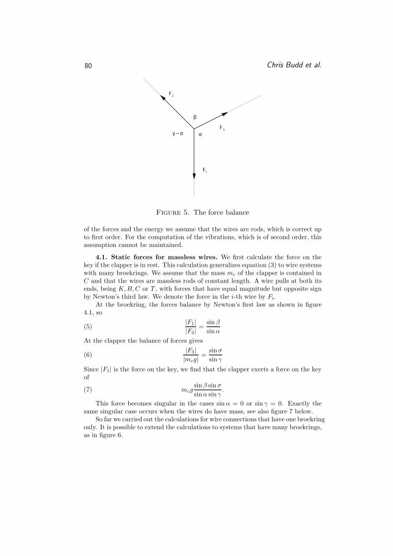
Figure 5. The force balance
of the forces and the energy we assume that the wires are rods, which is correct upto first order. For the computation of the vibrations, which is of second order, thisassumption cannot be maintained.
4.1. Static forces for massless wires. We first calculate the force on thekey if the clapper is in rest. This calculation generalizes equation (3) to wire systemswith many broekrings. We assume that the mass mc of the clapper is contained inC and that the wires are massless rods of constant length. A wire pulls at both itsends, being K, B, C or T , with forces that have equal magnitude but opposite signby Newton’s third law. We denote the force in the i-th wire by Fi.
At the broekring, the forces balance by Newton’s first law as shown in figure4.1, so
(5)|F1||F3|
=sin β
sinα
At the clapper the balance of forces gives
(6)|F3||mcg|
=sinσ
sin γ
Since |F1| is the force on the key, we find that the clapper exerts a force on the keyof
(7) mcgsinβ sin σ
sinα sinγ.
This force becomes singular in the cases sin α = 0 or sin γ = 0. Exactly thesame singular case occurs when the wires do have mass, see also figure 7 below.
So far we carried out the calculations for wire connections that have one broekringonly. It is possible to extend the calculations to systems that have many broekrings,as in figure 6.

Hanging a Carillon in a Broek-system 81
Figure 6. Two broekrings
4.2. Configuration with more broekrings. In a more general configura-tion, the wire connects the key to the bell by k broekrings Ri, i = 1, . . . , k. Fol-lowing exactly the same procedure as above, we obtain 2(k + 1) conditions fromlinearising the fixed distances |T − C|, |C − Rk|, |Ri − Hi| and |Ri − Ri−1|, whereR0 = K and the positions of C and the broekrings Ri are unknown. If we assumethat, as before, all the points remain in one plane there are 2(k + 1) equationswith 2(k + 1) unknowns (the coordinates of C and the Ri). In this case, dRi canbe computed from dRi−1. Let αi be the angle between the wire connecting Ri
to Ri−1 and the wire connecting Ri to Hi. And, let βi be the angle between thewire connecting Ri to Ri+1 and the wire connecting Ri to Hi. The angles αi andβi are shown in figure 6 for two broekrings. Then the relation between the dis-tances dRi and dRi−1 over which the broekrings move, can be obtained from theabove equations in a similar way as for the one broekring system, and it is given by|dRi|/|dRi−1| = sin(βi−1)/sin(αi). We introduce the notation
(8) wi =sin(βi−1)
sin(αi)

82 Chris Budd et al.
and call this the index at the i-th broekring. For a system with k broekrings, theratio |dC| : |dK| is the product over all the indices with an additional contributionof the angles at the clapper, according to the following formula
|dC||dK| =
|dC||dRk|
· |dRk||dRk−1|
· · · |dR2||dR1|
· |dR1||dK|
=1
sin(α1)
k∏
i=1
wi(9)
where we assume that the displacement of the key dK = dR0 is vertical. In thesimple configuration with one broekring this again reduces to
(10)|dC||dK| =
sin(β)
sin(γ) sin(α).
As mentioned in Section 2, the fraction |dC| : |dK| is important for the design ofthe carillon and again we can influence it by moving the hinges
Rule of thumb. If you want to increase the ratio |dC| : |dK| then raise the hinge
of the first broekring keeping the angle γ fixed or lower the position of the first
broekring keeping the hinge fixed.
4.3. The Lagrangian of the system with massive wires. To find an ex-pression for the force that is needed to play a key in case the masses of the wiresare relatively large, we calculate the total energy for a single bell system, and thechange in potential and kinetic energy under a small vertical displacement dK ofthe key.
The natural way to describe this mechanical system is by computing its La-grangian. In order to obtain the total energy, we first determine the potentialenergy and the kinetic energy in every single point in the system and then integrateover the wires. We shall need second order approximations.
4.4. Potential energy. For the computation of the potential energy of thewhole system, it is important to know where the gravitational force on each wireand on the clapper works, so where the center of mass is located. As the clapper isa rather thin pole with a large massive ball at the hanging end, we assume that allthe mass of the clapper is located in this end. The wires are more or less uniform,so we can take their centers of mass in the middle of each wire. Suppose that thecoordinates of the end points of a uniform wire are a = (a1, a2) and b = (b1, b2).Then the potential energy of the wire is mg(a2 + b2)/2, where m denotes its mass.This applies to wires 2 and 3. We treat wire 1 in a different way, since both theweight of this wire and the force on the key approximately work along the sameline in the vertical direction. The force on the key is always present: in rest, thekey is blocked from above to prevent it from moving upward since without thisblocking the rather heavy clapper would move to its preferred, vertical position.(Recall that the distance of the clapper to the bell in rest should be only 2 - 5 cm.,so σ > 0.) When a bell is played, this force should first be overcome and then someadditional force should be applied to move the clapper. We simply put this forceand the gravitational force on the wire into one ‘tension’ τ , which in fact consists of

Hanging a Carillon in a Broek-system 83
the tension in rest (directed upwards and canceled by the blocking force) and the(downward) tension added by the player.
The potential energy depends on the end points K, R, C, H of the wires. Denotethe coordinates of K, R, H, C in the initial position by (K1, K2), (R1, R2), (H1, H2)and (C1, C2) respectively. Under the assumption of uniform mass distribution, thepotential energy of the system in equilibrium is given by
V0 = C2(mc +m2
2)g + R2
(m2 + m3)g
2+ H2
m3g
2+ K2τ
Let V (dK) be the potential energy of the system, with the key in vertical positionK2 + dK, such that V (0) = 0. (This means that V(dK) is the relative potentialenergy with respect to equilibrium.) Under the above assumptions on the centersof mass the potential energy of the system is given by
V (dK) = dC2(mc +m2
2)g + dR2
(m2 + m3)g
2+ dKτ
In equation (4) we find the linear dependence of dC2 and dR2 on dK. The linearpart of the Lagrangian determines the equilibrium. We also need the quadratic partonce we consider the vibrations of the system. Introducing the exact angles α+dα,β + dβ, γ + dγ and σ + dσ after displacement, this quadratic part can be computedusing geometrical constraints and Taylor expansions. We found that
V (dK) = dK(
(mc + m2
2 )g sin σ sin βsin γ sin α
+ (m2+m3)g2 + τ
)
+ dK2
2 sin2 α·(
mcgcos σ sin2 β
l0 sin2 γ+ m2g
cos(σ−γ) sin2(σ−α)2l2 sin2 γ
− m3g cos α2l3
)
+ O(dK3)
Note that, since RH is attached to the wall, the potential energy involving m3
must equal the potential energy for a simple rod hinged at H . This is indeed thecase.
4.5. Kinetic energy. Consider a rod of uniformly distributed mass m thatis moving. Its movement can be described by the coordinates of its end pointsa, b depending on time. If we denote the derivative with respect to time of thecoordinates a and b by a, b, then the kinetic energy of the rod is
1
2m
∫ 1
t=0
|ta + (1 − t)b|2dt =m(|a|2 + 〈a, b〉 + |b|2)
6.
So the kinetic energy of the broek-system is given by
m1(|K|2 + 〈K, R〉 + |R|2)6
+m2(|R|2 + 〈R, C〉 + |C|2)
6+
m3|R|26
+mc|C|2
2.
In section 3 we computed the relations between dK, dR and dC and we found that
|dR| = |dK|/sinα , ∠(dR, dK) = α − π2
|dC| = |dK| sin βsin α sin γ
, ∠(dR, dC) = β + γ

84 Chris Budd et al.
Figure 7. Two singular cases. When the key-wire is vertical,the broek-wire and key-wire hang along the wall in the righthand case
Denote the ratio |dR|/|dK| by ρR and the ratio |dC|/|dK| by ρC . Then using
relations as R = KdR/dK, the kinetic energy in terms of K is
T (K) =1
6|K|2
(
m1(1 + ρR sin α + ρ2R) + m2(ρ
2R + cos(β + γ)ρRρC + ρ2
C)+
+m3ρR2 + 3mcρ
2C
)
.(11)
4.6. Lagrangian motion. With the obtained T and V we can write downthe Lagrangian L = T − V of the system, and hence the equations of motion
d
dt
∂L∂K
− ∂L∂K
= 0.
Here ∂L∂K
can be seen as the force in the system, which derives in this case from apotential. In equilibrium, the force acting on the system should be equal to zero,meaning that ∂L
∂K= − dV
dK= 0 in equilibrium. This immediately gives a relation
for τ , since it means that the coefficient of the linear part of V should be zero.The O(dK2) terms in V have to balance with T . From this we can derive naturalfrequencies of the system, that can give a clue about the amount of vibration onecan expect in the wires.
We will do these calculations in a system with massless wires. In this case thesystem should more or less satisfy the ‘classical’ intuition; therefore it is a goodcheck for our calculations.
4.7. Dynamics of massless wires. In case of massless wires only terms con-cerning the clapper remain. From dV
dK= 0 we derive in this case
(12) τ = mcgsin σ sin β
sin γ sin α
which is exactly the same expression as (7). This becomes singular in the casessinα = 0 or sinγ = 0. Exactly the same singular cases appear in the full expressionfor τ when the wires do have mass. From the sketches 7 it is immediately clear that

Hanging a Carillon in a Broek-system 85
Figure 8. A massless system that does not exert a force onthe key
it should indeed cost an infinite amount of work to move the key or clapper whenthe configuration satisfies either case.
In this massless case it is also easy to understand how the system should behavewhen there is no tension at all, so when the key is not blocked or played. The systemthen just hangs, and one would expect that the clapper would hang in its preferred,vertical position or would somehow not be able to reach that position. This indeedfollows from the assumption τ = 0: the solutions are sinσ = 0 and sinβ = 0,leading to the configurations in figure 8.
4.8. Swinging and vibration. In reality a wire is not a rod but it is an elasticstring. The key strokes induce displacements of the broekrings, causing vibrations.This vibration should not be too much, since the wires are, in an ideal situation,not allowed to touch each other. To get an idea about the possible vibration, wederive the natural frequencies of the system from the Hamiltonian H = T + V ,These natural frequencies tell us what happens if you twang a wire.
For massless wires, putting H = 0 and comparing equations 4.4 and 11 yieldsthe differential equation
K2 =g cos(σ)
l0dK2.
Recall that the coefficient of the linear term in V is zero. If we put x = eiωt, thisresults in
ω = 2πf =
√
g cos(σ)
l0.
Here f is the frequency. For typical values of the parameters, say l0 = 0.5, cosσ =0.8, this results with g = 10 in ω = 4, or a frequency of about 0.6 Hz. From ourobservations in the church we estimated a frequency of 0.2 Hz.
The same kind of calculations can be done for wires with mass, for which oneends up with more complicated expression that we do not display here.
When playing the carillon, the vertical wire will always move a bit. But sincethe vertical wires are all attached to the keyboard, they are very close to each

86 Chris Budd et al.
other, even when they are in rest. This means that a small sidewards movementcan already cause touching wires, which we should prevent.
It is difficult to give a precise bound on the amplitude, since this will depend onthe geometry, the tension and the number of key strokes during play. However, weobserved that the maximal amplitude of the vibration occurs at the first broekringR1 at the end of the vertical first wire segment. Its displacement twangs the wire,as represented by the horizontal component of dR1. When the vertical movement ofthe wire is dK, the sideways swing of the wire at the position R1 is approximatelydR1 = dK/ tanα, which means that the configuration should optimally satisfyα = π/2.
Rule of thumb. The vibration of the first broekring can be damped by putting
the hinge at the same level as the ring.
4.9. Playing the carillon. We have already addressed some rules of thumbfor the angles in the system, that follow from conditions on the swing when playingthe carillon. However, we did not mention the requirement that is maybe the mostimportant one: the keyboard player roughly wants every key to ‘feel’ the same. Thebasses may need some more force to play than the trebles, but the amount of forcethat is needed to play neighbouring tones should not differ much. We suppose thatthe travel dK is constant for all keys, i.e., that the difference between the upperand the lower position is the same for each key. The question now is: under whatconditions is the tension that the player should add to play a bell (about) the samefor each key?
A first idea can again be obtained from the system with massless wires. We as-sume that there is a weight W that ‘helps’ the player to move the key down (whichis in our former calculations incorporated in τ). This weight may contain the massof the wires, that we assume to be concentrated at the key, if not negligible. Sincethe total energy should be remained, this means that the following should be satis-fied:
Energy input by player = potential energy gain of clapper - energy lost by help.
Note, that the clapper moves upward when the key is played, while the helpingweight moves downward. This means that the clapper gains potential energy, whilethe weight loses potential energy. In a formula we have
(13) τplayerdK = mcgl0 sinσ · dσ − WdK.
If each key should need the same amount of added tension, this means that τplayerdKshould be constant. In other words, for W = 0 we obtain the restriction
(14) mcl0 sin σ · dσ = C,
where C is the same constant for all bells!However, detailed information about the St. John’s tower in Gouda tells us
that this requirement is impossible to satisfy. There the specification of the bellsgives:

Hanging a Carillon in a Broek-system 87
large bell l0 sin σ ≈ 50 cm, mc ≈ 30 kgsmall bell l0 sin σ ≈ 10 cm, mc ≈ 0.3 kg.
To impose (14) for this tower, the angles of swing in the smallest and the largestbells should satisfy
dσlarge = 50 · dσsmall,
which is impossible (it would for instance mean that a small bell would move by1 degree and a large one by 50 degrees). This actually tells us, that the helpingweight W is really needed at the larger bells to obtain an evenly played keyboard.
These calculations nicely correspond to our observations. In a real carillonsystem the wires are always very long and quite thick, and have a total mass ofup to 1 kg. This means that the mass is not negligible for small bells with clapperweights of only 0.3 kg. The mass of the wires that we put in W may even be so largecompared to mc, that the right hand side of (13) is negative. This would mean thathelp is needed to move the clapper back to its original position, which is indeed thecase in real carillons. We observed that some of the smaller clappers had a springto move them back after they had been played.
On the other hand, we observed springs that helped to move the keys of largerbells, which could account for the extra weight W needed in order to obtain anevenly played keyboard.
5. The 3D configuration of the broek-system
There are two interesting optimization problems related to the placement ofbells in a tower. In the first problem we view the tower from above and we try,mainly to get an idea of the situation, to find a configuration such that the inter-section points (of the projections) of the wires are as far apart from each other aspossible. Of course there is no guarantee that this configuration is the best in thethree dimensional case.
In the second optimization problem we try to approximate the three-dimensionalreal situation in a belfry. Then we would like to maximize the smallest distancebetween all the wires so that they’re as far apart from each other as possible toavoid that they will touch when the carillon is played.
5.1. The two-dimensional problem. Given the possible positions of thebells ({bi ∈ R
2 | i = 1, 2, . . . , n}) on the circumference of the tower and the positionof the attachment points to the keys ({ki ∈ R
2 | i = 1, 2, . . . , n}) in the keyboard,the place of each wire, being a straight line through these two points, is uniquelydetermined. If we start with n keys and n bells, then the wires will intersect in (atmost) 1
2 (n− 1)n points. Our aim is to design the configuration of the bells in sucha way that these intersection points lie as far apart as possible. Therefore, we firstlook at the distances between all these points. There are
(
12 (n − 1)n
2
)
distances between the intersection points which need to be computed. Among thesedistances we have to find the smallest distance and then the optimization problemis to decide which positioning of the bells maximizes this minimal distance. A

88 Chris Budd et al.
Figure 9. A belfry with a radius of 2 m with 15 bells seenfrom above. The distance between the intersections is neverless than 1.31 cm.
computer program which tries different permutations of the bells randomly canapproximate the maximum. However, this is a quite cumbersome task since for nbells there are n! configurations that need to be checked. Thus for one level in abelfry with 15 bells, it will take 0.714 · 1016 computations, and for a belfry with 45bells the number of computations will be 0.586 · 1062.
Computations with Matlab yield for a belfry with 15 bells and a radius of 2 mafter a 698 tries, a configuration where each distance between two intersections isgreater than 1.3 cm (see figure 9).
Notice that there are two more general interesting geometrical questions con-nected to this problem. The first question, important to obtain a good estimatein the optimization problem, is the following. How should n points be placed ina unit disk, such that the smallest distance between two points is maximal? For
n = 2, 3, 4, 5, 6, this distance is 2,√
3,√
2,√
(5 −√
5)/2, 1, respectively, and the
points have to be placed on the boundary. For n = 7 the maximal distance is also1, but one point has to be placed in the interior of the disk. But what about highern?
The second question is the following: consider two sets of n colored points inthe real plane, {bi ∈ R
2 | i = 1, 2, . . . , n} (blue, the keyboard) and {ki ∈ R2 |
i = 1, 2, . . . , n} (black, the bells). How can we connect each of the blue pointswith a different black point with a straight line such that the distance between theintersection points is as large as possible.
5.2. The three-dimensional problem. Let us now consider the belfry inthree dimensions. So, assume we can place bells in an equidistant way on the

Hanging a Carillon in a Broek-system 89
Figure 10. A belfry with a radius of 2 m with 15 bells. Thedistance between the wires is greater than 2.95 cm.
circumference of the belfry, where the height is free to choose. Also, we assumethat the wires which connect the broekring to the wall are all attached to the wallat a fixed height on the circumference of the belfry. Then we find that once thehorizontal position of the bell is chosen, the vertical position of the bell is completelydetermined by the formulas
{
sin βsin γsin α
= |dC||dK|
α + β + γ − 2π = σ
because |dC|/|dK| and σ are fixed (see figure 4). Starting with an arbitrary per-mutation of the bells, we compute the height of each bell by the above formulas,and then we compute all the distances between the pieces of wire. We would againlike the smallest of these distances to be as large as possible. It is astonishing thatit is hard to find good configurations by a random permutation of the bells. After1112 permutations of 15 bells in a belfry with a radius of 2 meters we find thatfor the optimal configuration the smallest distance is 2.95 cm (see figure 10). Thegeometrical character of this problem is similar tot the two-dimensional case.
Acknowledgments
A large part of this work was done during the Study Group with Industry inFebruary 2003 in Leiden, in cooperation with the group members Miguel Frasson,Nick Ovenden, Nicole Rommelse and Floske Spiekstra.

90 Chris Budd et al.
Bibliography
[1] Andre Lehr Some mathematical background of the broek-system (in Dutch),Nationaal Beiaardmuseum, 2003.