happyhunterbuild - northwest r/c ship modelers - … first step after accounting for all the items...
TRANSCRIPT

HAPPY HUNTER BUILD LOG
After finishing a Billings model of the Calypso in January, 2012, I decided to build a model of the Happy Hunter, a Robbe kit I had stashed
from an earlier purchase. The four pictures show the kit contents and vacu-formed ABS hull. There were several sheets of scribed ABS parts to be cut out which considerably reduced the build time. It was easy to bend the material along the scribed lines and simply snap the parts free from the remainder. The first step after accounting for all the items was to wet sand the hull inside and outside to remove any wax or other contaminants from the molding and manufacturing process. The hull was well made and much stronger than the vacu-formed hulls from other model suppliers. Shaft logs, rudder posts and Kort nozzle supports were secured with epoxy 20 minute glue using scrap material to create boundaries to keep the epoxy contained. Blue modelers’ clay was also employed to keep the epoxy contained. See pictures 3042, 3043, 3045, and 3046. The Kort nozzle brackets were wired together at their midpoint joint surfaces. Tape was placed around exits from the hull to prevent leakage of epoxy. Brass rods were placed through the Kort
3036 3037
3038 3039

brackets, as seen in picture 3043, for increased strength and holding within the epoxy resin. Blue clay was placed around the shaft log exits as seen in picture 3049. Rudder posts, the Kort nozzle brackets and lead shot are seen in
3042 3043
3045 3046
30493048
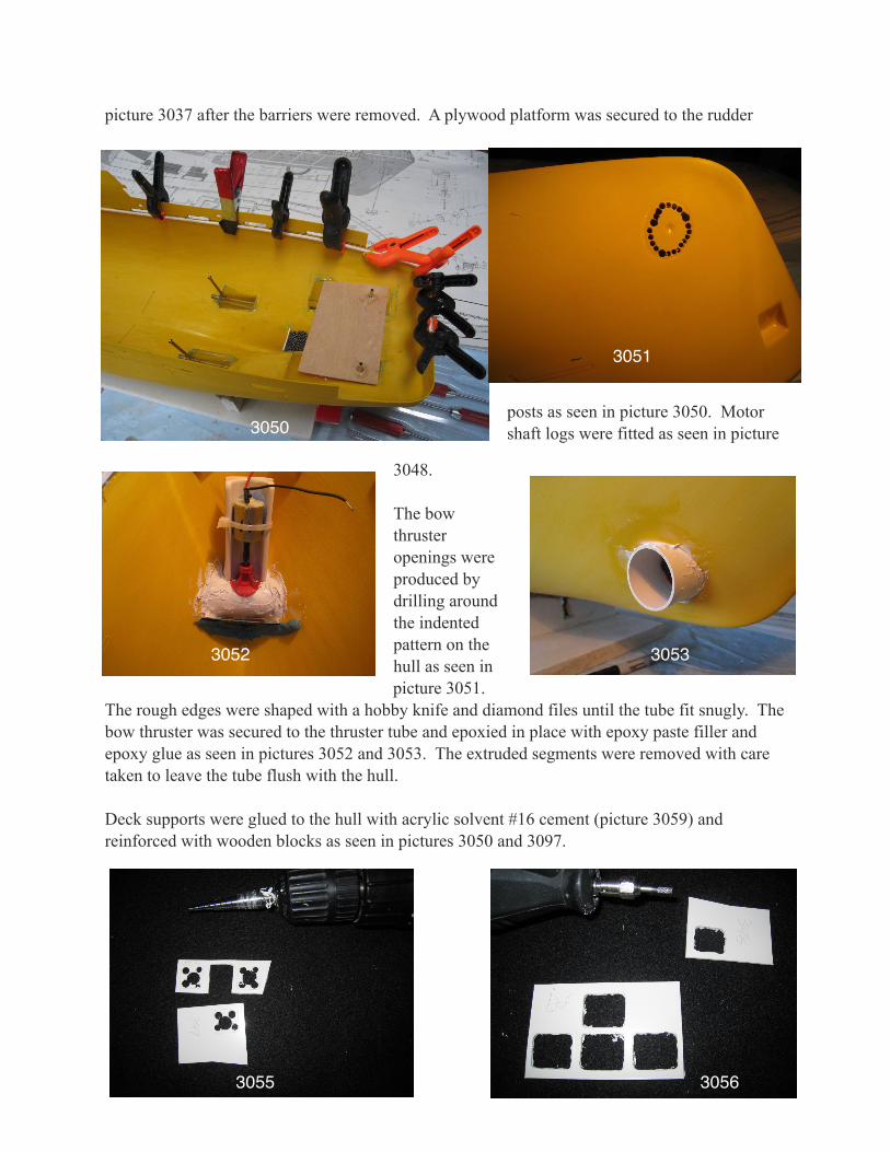
picture 3037 after the barriers were removed. A plywood platform was secured to the rudder
posts as seen in picture 3050. Motor shaft logs were fitted as seen in picture
3048. The bow thruster openings were produced by drilling around the indented pattern on the hull as seen in picture 3051.
The rough edges were shaped with a hobby knife and diamond files until the tube fit snugly. The bow thruster was secured to the thruster tube and epoxied in place with epoxy paste filler and epoxy glue as seen in pictures 3052 and 3053. The extruded segments were removed with care taken to leave the tube flush with the hull. Deck supports were glued to the hull with acrylic solvent #16 cement (picture 3059) and reinforced with wooden blocks as seen in pictures 3050 and 3097.
3050
3051
3052 3053
3055 3056
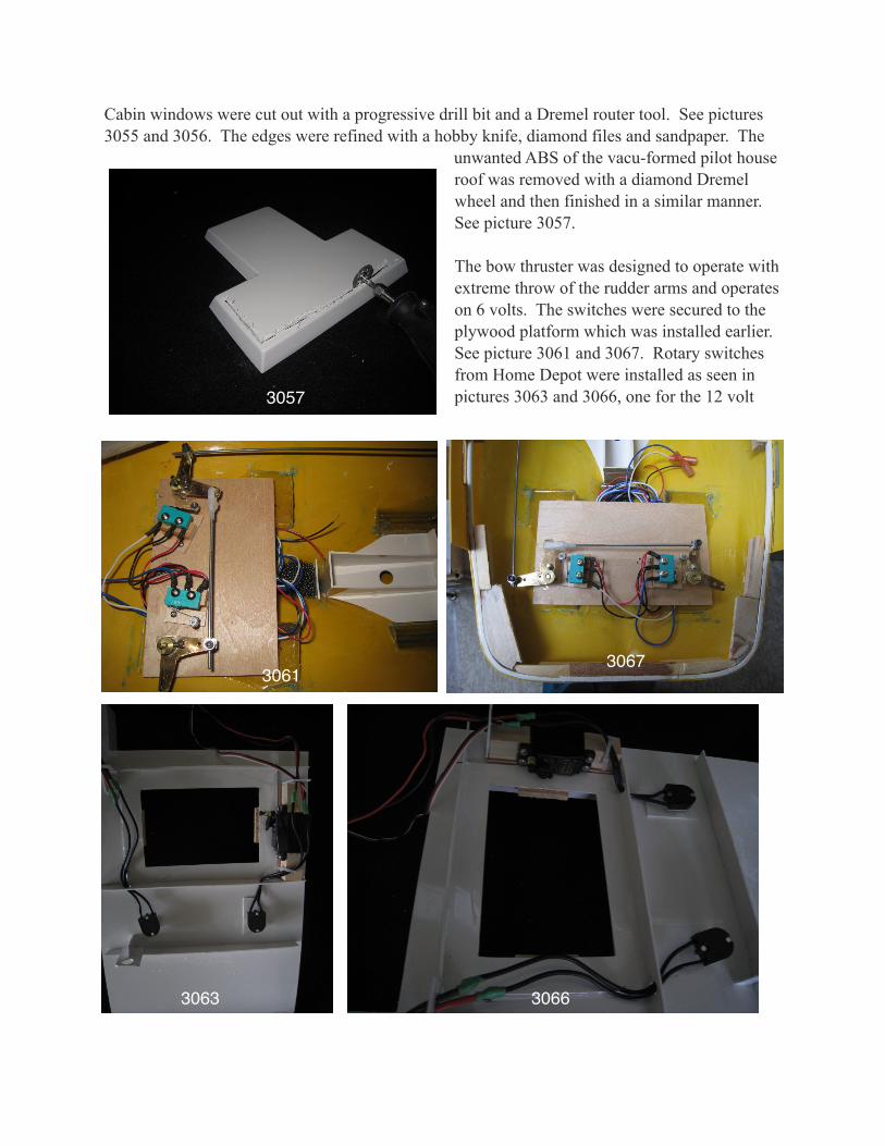
Cabin windows were cut out with a progressive drill bit and a Dremel router tool. See pictures 3055 and 3056. The edges were refined with a hobby knife, diamond files and sandpaper. The
unwanted ABS of the vacu-formed pilot house roof was removed with a diamond Dremel wheel and then finished in a similar manner. See picture 3057. The bow thruster was designed to operate with extreme throw of the rudder arms and operates on 6 volts. The switches were secured to the plywood platform which was installed earlier. See picture 3061 and 3067. Rotary switches from Home Depot were installed as seen in pictures 3063 and 3066, one for the 12 volt 3057
30613067
3063 3066
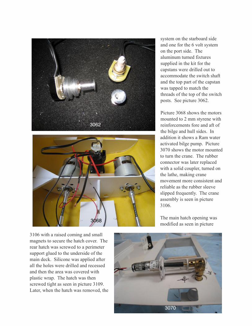
system on the starboard side and one for the 6 volt system on the port side. The aluminum turned fixtures supplied in the kit for the capstans were drilled out to accommodate the switch shaft and the top part of the capstan was tapped to match the threads of the top of the switch posts. See picture 3062. Picture 3068 shows the motors mounted to 2 mm styrene with reinforcements fore and aft of the bilge and hull sides. In addition it shows a Ram water activated bilge pump. Picture 3070 shows the motor mounted to turn the crane. The rubber connector was later replaced with a solid coupler, turned on the lathe, making crane movement more consistent and reliable as the rubber sleeve slipped frequently. The crane assembly is seen in picture 3106. The main hatch opening was modified as seen in picture
3106 with a raised coming and small magnets to secure the hatch cover. The rear hatch was screwed to a perimeter support glued to the underside of the main deck. Silicone was applied after all the holes were drilled and recessed and then the area was covered with plastic wrap. The hatch was then screwed tight as seen in picture 3109. Later, when the hatch was removed, the
3062
3068
3070
plastic wrap was easily removed and the silicone seal was smooth and hopefully will provide a watertight seal. Unscrewing the hatch is not a big effort and
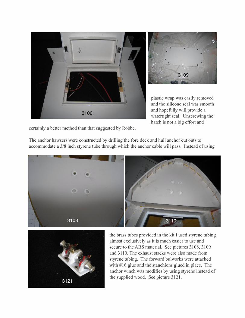
certainly a better method than that suggested by Robbe. The anchor hawsers were constructed by drilling the fore deck and hull anchor cut outs to accommodate a 3/8 inch styrene tube through which the anchor cable will pass. Instead of using
the brass tubes provided in the kit I used styrene tubing almost exclusively as it is much easier to use and secure to the ABS material. See pictures 3108, 3109 and 3110. The exhaust stacks were also made from styrene tubing. The forward bulwarks were attached with #16 glue and the stanchions glued in place. The anchor winch was modifies by using styrene instead of the supplied wood. See picture 3121.
3106
3109
31103108
3121

The doors, windows and vents were glued to card board with glue sticks, then primed and painted. The vents were constructed with styrene rail- road siding material and bordered with styrene strips rather than applying the paste on decals as provided in the kit. See picture 3124. The capstan plastic surrounds and aluminum pieces were likewise glued to cardboard and primed and painted. See picture 3223. After the round brass portholes were painted they were removed and secured to a piece of Lucite plastic with a glue stick. When dry, clear epoxy resin was used to create clear windows instead of the supplied blue plastic cut outs. The remainder of the small finished items were pinned with .032 brass wire, clamped with hemostats and painted. See picture3224. To add strength the bits were pinned with 1/16 brass rod. The decks and bulwarks were drilled and the bitts glued with Goop, all purpose contact
adhesive. Using a pointed artist’s pallet knife works very well for applying small amounts of this adhesive. See picture 3225.
The main propulsion motors were supplied by Robbe and connected to Roboesch universals.
3124
3223
3224
3225

Those used to turn and lift the crane and operate the winch were small geared (10-30 rpm) motors purchased from E-Bay. The bow thruster assembly was a double propeller unit from
Robbe. Picture 3257 shows the reversing mechanism for the motors used to operate the crane functions and towing winch. After getting everything in place, some difficulty was encountered with servo glitching. So, capacitors were placed on all three motors and a new servo replaced for the one that was acting up. Originally, the servos and motors were attached to plywood with Goop, but in removing them
the bond was so tight that the plywood was delaminated. The plywood was replaced with 3/16th inch Lucite plastic. See picture 3283.
Railings were soldered to the stanchions in place, using a Tritan resistance
soldering tool, sold by Micro Mark. See picture 3282. This tool is quite well suited for this task. The joint is clamped by squeezing the trigger and with further pressure the circuit is completed, heating the joint so that the solder starts melting. As the trigger is released slowly the circuit is broken. The joint can then be held until the solder has hardened. The trigger then is released and
3257
3283 3282
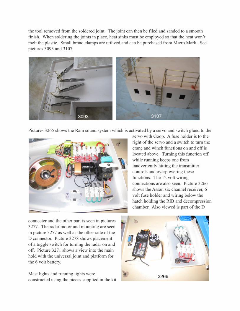
the tool removed from the soldered joint. The joint can then be filed and sanded to a smooth finish. When soldering the joints in place, heat sinks must be employed so that the heat won’t melt the plastic. Small broad clamps are utilized and can be purchased from Micro Mark. See pictures 3093 and 3107.
Pictures 3265 shows the Ram sound system which is activated by a servo and switch glued to the
servo with Goop. A fuse holder is to the right of the servo and a switch to turn the crane and winch functions on and off is located above. Turning this function off while running keeps one from inadvertently hitting the transmitter controls and overpowering these functions. The 12 volt wiring connections are also seen. Picture 3266 shows the Assan six channel receiver, 6 volt fuse holder and wiring below the hatch holding the RIB and decompression chamber. Also viewed is part of the D
connecter and the other part is seen in pictures 3277. The radar motor and mounting are seen in picture 3277 as well as the other side of the D connector. Picture 3278 shows placement of a toggle switch for turning the radar on and off. Picture 3271 shows a view into the main hold with the universal joint and platform for the 6 volt battery. Mast lights and running lights were constructed using the pieces supplied in the kit
3093 3107
3266

into which 1.8 mm warm LED’s were placed. The red and green running lights were dipped into Tamiya clear colors as were the other red lights called for in the plans. The LEDs were wired in series taking into account the number of volts consumed, the difference made up by using the appropriate resistors. All circuits terminated in a PCB board as seen in picture 3276. An LED was placed on either side of the capstans - 12 volt on the starboard side and 6 volt on the port side. This indicates that the power systems are turned on. Having the switches in the capstans really lends itself to ease of operation as the superstructure doesn’t need to be removed to turn the power on and off. The 12 volt system energizes the main power and receiver which is powered by the BEC of the port ESC.
3277
3278
32713276
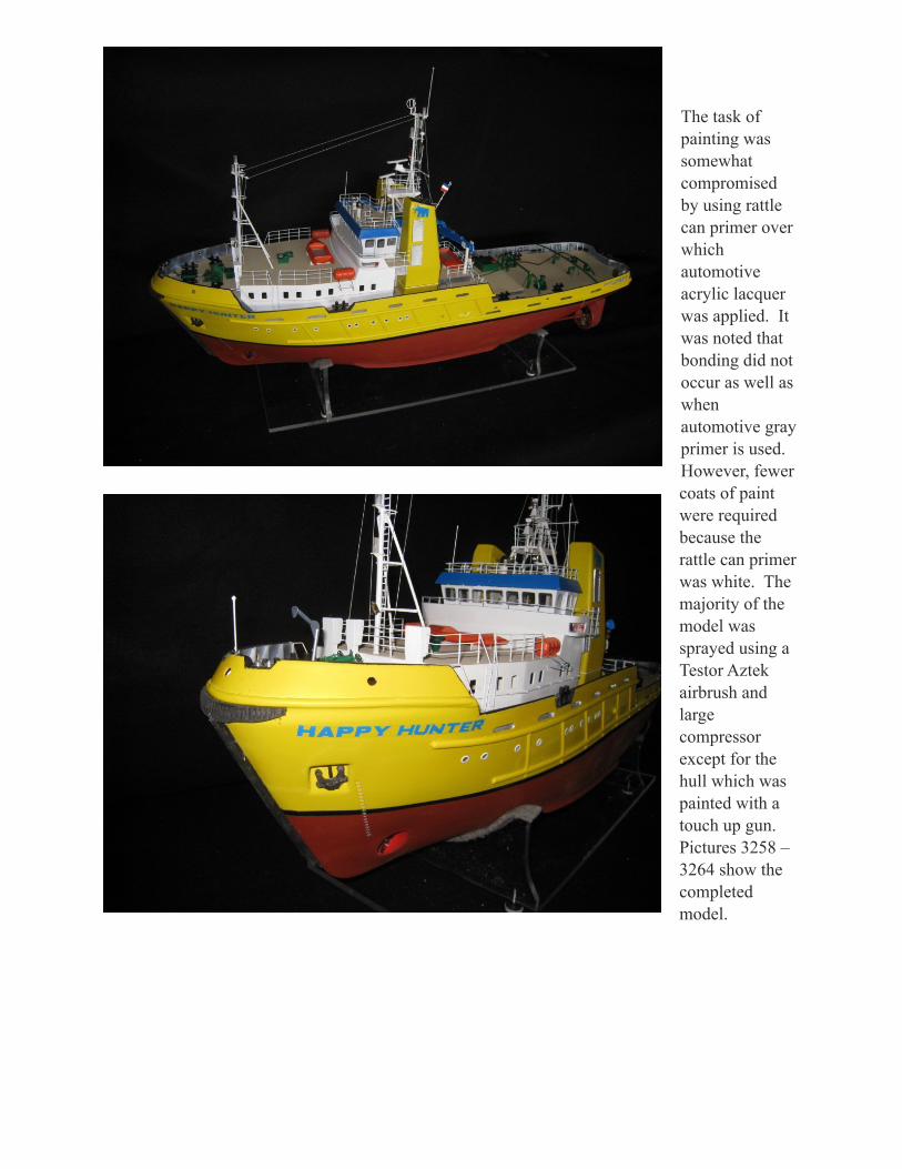
The task of painting was somewhat compromised by using rattle can primer over which automotive acrylic lacquer was applied. It was noted that bonding did not occur as well as when automotive gray primer is used. However, fewer coats of paint were required because the rattle can primer was white. The majority of the model was sprayed using a Testor Aztek airbrush and large compressor except for the hull which was painted with a touch up gun. Pictures 3258 – 3264 show the completed model.