hard to resist - ibselectronics.biz catalog.pdf · facilities in senai, malaysia, asj manufactures...
TRANSCRIPT

Hard to resist
w w w . a s j . c o m . s g
Product catalog

ForewordASJ was formerly known as AIRCO (S) Pte Ltd, a divison
of AIRCO Speer Electronics Inc. (USA). Established in
Singapore since 1969, AIRCO started out with manufacturing
capabilities of Carbon and Metal Film leaded resistors.
In 1980, AIRCO divested away from resistive products, and
formed the company named ASJ Pte Ltd.
ASJ Pte Ltd and it’s manufacturing plants are positioned
under ASJ Holdings group of companies. ASJ Holdings was
the first resistor manufacturer to be listed on the Singapore
Stock Exchange in January 1997, and thereafter, listed on the
Mainboard of the Singapore Stock Exchange in 2002.
With its sales headquarters in Singapore and manufacturing
facilities in Senai, Malaysia, ASJ manufactures and distributes
quality resistors, providing essential support to a diverse
base of customers from various market segments. The
close proximity of the sales headquarters and manufacturing
facilities allowed great flexibility and on time delivery support
to our extensive network of customers, which spans across
Asia, Europe and the United States of America. Flourishing
its’ reputation over the years, ASJ is now one of the largest
chip resistors manufacturers in South Asia.
Mission Enhance customer satisfaction by continuous
improvement and commitment to provide high quality
products
Continual expansion of ASJ resistors global
presence
Encompassing range of resistive products
Foster an environment that encourages continual
improvement to respond to the changing needs of
customers
Page
1.0 Product Lineup 2-8
2.0 SMD Resistors Section
2.1 Thick Film
2.1.1 General Purpose Thick Film Chip Resistors 10
2.1.2 Precision Thick Film Chip Resistors 12
2.2 Thin Film
2.2.1 General Purpose Thin Film Chip Resistors 14
2.2.2 Precision Thin Film Chip Resistors 16
2.2.3 Thin Film Current Sensing Chip Resistors 18
2.3 Current Sensing
2.3.1 Milli Ohm Thick Film Chip Resistors 20
2.3.2 Ultra-Low Ohmic Thick Film Chip Resistors 22
2.3.3 Low Ohmic High Power Current Sensing Chip Resistors 24
2.3.4 Metal Element Current Sensing Chip Resistors 26
2.4 Power Chip
2.4.1 High Power Rating Chip Resistors 28
2.4.2 Medium Voltage Chip Resistors 30
2.4.3 High Voltage Chip Resistors 32
2.5 High Ohmic
2.5.1 High Ohmic Value Chip Resistors 34
2.5.2 Ultra-High Ohmic Value Chip Resistors 36
2.5.3 Precision High Ohmic Value Chip Resistors 38
2.6 Array & Networks
2.6.1 Thick Film Chip Resistor Array 40
2.6.2 Thick Film Chip Resistor Network 42
2.6.3 Thin Film Chip Resistor Array 44
2.6.4 Thick Film SIP Networks 46
2.6.5 Precision Thin Film SIP Networks 48
2.7 Speciality
2.7.1 Anti-Sulphur Thick Film Chip Resistors 50
2.7.2 Trimmable Thick Film Chip Resistors 52
2.7.3 SMD Wirewound Resistors (Chip Type) 54
3.0 Packaging / Taping Specifications (SMD)
3.1 Chip Resistors Packaging / Taping 56
3.2 Array Packaging / Taping 57
3.3 Speciality Packaging / Taping 58
3.4 Packing Quantity 59
3.5 Soldering Pad Dimensions 60
4.0 Marking Information
4.1 Resistance Value Code 61
4.2 SMD Chip Resistors Marking Diagrams 62

5.0 Leaded Resistors Section
5.1 Metal Film
5.1.1 General Purpose Metal Film Resistors 64
5.1.2 Precision Metal Film Resistors 66
5.1.3 High Precision Metal Film Resistors 68
5.1.4 Flame-Proof Metal Film Resistors 70
5.1.5 High Power Flame-Proof Metal Film Resistors 72
5.1.6 Fusible Metal Film Resistors 74
5.2 Carbon Film
5.2.1 General Purpose Carbon Film Resistors 76
5.2.2 Flame-Proof Carbon Film Resistors 78
5.3 Metal Oxide
5.3.1 Flame-Proof Metal Oxide Resistors 80
5.4 Metal Glaze
5.4.1 Pulse Loading Metal Glaze Resistors 82
5.5 WireWound
5.5.1 Flame-Proof Coating WireWound Resistors 84
5.5.2 High Power Flame-Proof WireWound Resistors 86
5.5.3 Fusible Flame-Proof WireWound Resistors 88
5.6 Cement
5.6.1 Cement Axial Lead Type Resistors 90
5.6.2 Cement Vertical Lead Type Resistors 92
5.6.3 High Power Cement Vertical Lead Type Resistors 94
5.6.4 Cement Radial Terminals Type Resistors 96
5.6.5 Rectangular Cement Clamp Mounting Type Resistors 98
5.6.6 Cement Radial Lead Type Resistors 100
5.6.7 Fusible Thermal Cement Type Resistors 102
5.7 Jumper
5.7.1 Zero Ohm Jumper Leaded Resistors 104
5.7.2 Jumper Wires 106
5.8 Speciality
5.8.1 Aluminium Housed Resistors 108
6.0 Packaging / Taping Specifications (Leaded Resistors)
110
7.0 Marking Information
Leaded Resistors Marking information - Colour code 113
8.0 Nominal Standard Resistance Values 114
9.0 Manufacturing, Sales & Distribution Network
115

www.asj.com.sgProduct Lineup
2
Series TypeCase Size / Configuration
/ L x Ø / L x W x HPower Rating
(W)Resistance Range
(Ω)Resistance
Tolerance (%)T.C.R (ppm/°C)
THIC
K FI
LM C
HIP
RESI
STO
RS
CR
CR05 0201 1/201 ≤ R < 10
±1%, ±2%, ±5%-200 / +400
10 ≤ R ≤ 10M ±200
CR10 0402 1/16
10 ≤ R < 1M
±1%, ±2%, ±5%
±100
1 ≤ R < 10, 1M≤ R <
10M±200
CR16 0603 1/10
10 ≤ R < 1M
±1%, ±2%, ±5%
±100CR21 0805 1/8
CR32 1206 1/4
CR40 1210 1/31 ≤ R < 10, 1M≤ R ≤
10M±200CR50 2010 3/4
CR63 2512 1
CR
CR05 0201 1/201 ≤ R < 10
±0.5%-200 / +400
10 ≤ R ≤ 10M ±200
CR10 0402 1/16
10 ≤ R < 1M
±0.5%
±100CR16 0603 1/10
CR21 0805 1/8
CR32 1206 1/4
1 ≤ R < 10, 1M≤ R ≤
10M±200
CR40 1210 1/3
CR50 2010 3/4
CR63 2512 1
THIN
FIL
M C
HIP
RESI
STO
RS
CT
CT10 0402 1/16 10 - 121K
±1% ±50
CT16 0603 1/10 1 - 681K
CT21 0805 1/8 1 - 1.5M
CT32 1206 1/8 1 - 1.5M
CT40 1210 1/4 1 - 1M
CT50 2010 1/2 10 - 1M
CT63 2512 3/4 10 - 1M
CT
CT10 0402 1/16
10 - 121K±0.1%
±25, ±50
10 - 100K ±10, ±15
10 - 121K±0.25%
±25, ±50
10 - 100K ±10, ±15
10 - 121K ±0.5% ±25, ±50
CT16 0603 1/10
1K - 47K ±0.05% ±10, ±15, ±25
10 - 681K±0.1%
±25, ±50
10 - 100K ±10, ±15
1 - 681K
±0.25%
±50
10 - 681K ±25
10 - 100K ±10, ±15
1 - 681K±0.5%
±50
10 - 681K ±25
CT21
CT32
0805
12061/8
100 - 100K ±0.05% ±10, ±15, ±25
10 - 1.5M±0.1%
±25, ±50
10 - 100K ±10, ±15
1- 1.5M
±0.25%
±50
10 - 1.5M ±25
10 - 100K ±10, ±15
1 - 1.5M±0.5%
±50
10 - 1.5M ±25
CT40 1210 1/4
100 - 100K ±0.05% ±10, ±15, ±25
10 - 1M±0.1%
±25, ±50
10 - 100K ±10, ±15
1 - 1M
±0.25%
±50
10 - 1M ±25
10 - 100K ±10, ±15
1 - 1M±0.5%
±50
10 - 1M ±25
CT50
CT63
2010
2512
1/2
3/4
100 - 100K ±0.05% ±10, ±15, ±25
10 - 1M±0.1%
±25, ±50
100 - 100K ±10, ±15
10 - 1M±0.25%
±25, ±50
10 - 100K ±10, ±15
10 - 1M ±0.5% ±25, ±50
CT
CT10 0402 1/16 0.5 ≤ R < 1 ±0.5%, ±1% ±50, ±100
CT16
CT21
0603
0805
1/10
1/80.2 - 0.3 ±0.5%, ±1% ±100
0.31 ≤ R < 1 ±0.5%, ±1% ±50
CT50
CT63
2010
2512
3/4
1
0.05 - 0.1
±0.5%, ±1%
±200
0.101 - 0.3 ±100
0.31 ≤ R < 1 ±50
CT633 2512 3 0.1 ≤ R < 1 ±1% ±100
Specifications given herein may be changed at any time without prior notice. Please confirm technical specifications with factory before use.
www.asj.com.sg Product Lineup
3
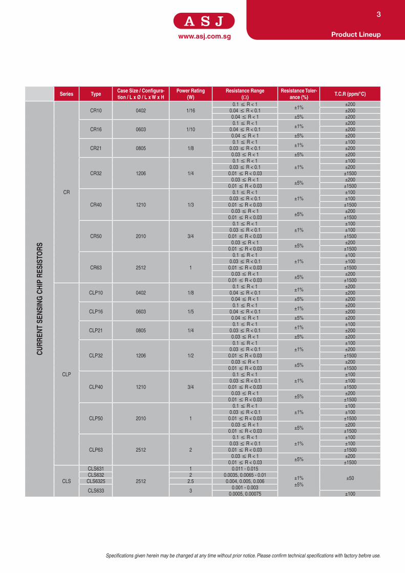
Series TypeCase Size / Configura-tion / L x Ø / L x W x H
Power Rating(W)
Resistance Range(Ω)
Resistance Toler-ance (%)
T.C.R (ppm/°C)
CURR
ENT
SENS
ING
CHI
P RE
SIST
ORS
CR
CR10 0402 1/16
0.1 ≤ R < 1±1%
±200
0.04 ≤ R < 0.1 ±200
0.04 ≤ R < 1 ±5% ±200
CR16 0603 1/10
0.1 ≤ R < 1±1%
±200
0.04 ≤ R < 0.1 ±200
0.04 ≤ R < 1 ±5% ±200
CR21 0805 1/8
0.1 ≤ R < 1±1%
±100
0.03 ≤ R < 0.1 ±200
0.03 ≤ R < 1 ±5% ±200
CR32 1206 1/4
0.1 ≤ R < 1
±1%
±100
0.03 ≤ R < 0.1 ±200
0.01 ≤ R < 0.03 ±1500
0.03 ≤ R < 1±5%
±200
0.01 ≤ R < 0.03 ±1500
CR40 1210 1/3
0.1 ≤ R < 1
±1%
±100
0.03 ≤ R < 0.1 ±100
0.01 ≤ R < 0.03 ±1500
0.03 ≤ R < 1±5%
±200
0.01 ≤ R < 0.03 ±1500
CR50 2010 3/4
0.1 ≤ R < 1
±1%
±100
0.03 ≤ R < 0.1 ±100
0.01 ≤ R < 0.03 ±1500
0.03 ≤ R < 1±5%
±200
0.01 ≤ R < 0.03 ±1500
CR63 2512 1
0.1 ≤ R < 1
±1%
±100
0.03 ≤ R < 0.1 ±100
0.01 ≤ R < 0.03 ±1500
0.03 ≤ R < 1±5%
±200
0.01 ≤ R < 0.03 ±1500
CLP
CLP10 0402 1/8
0.1 ≤ R < 1±1%
±200
0.04 ≤ R < 0.1 ±200
0.04 ≤ R < 1 ±5% ±200
CLP16 0603 1/5
0.1 ≤ R < 1±1%
±200
0.04 ≤ R < 0.1 ±200
0.04 ≤ R < 1 ±5% ±200
CLP21 0805 1/4
0.1 ≤ R < 1±1%
±100
0.03 ≤ R < 0.1 ±200
0.03 ≤ R < 1 ±5% ±200
CLP32 1206 1/2
0.1 ≤ R < 1
±1%
±100
0.03 ≤ R < 0.1 ±200
0.01 ≤ R < 0.03 ±1500
0.03 ≤ R < 1±5%
±200
0.01 ≤ R < 0.03 ±1500
CLP40 1210 3/4
0.1 ≤ R < 1
±1%
±100
0.03 ≤ R < 0.1 ±100
0.01 ≤ R < 0.03 ±1500
0.03 ≤ R < 1±5%
±200
0.01 ≤ R < 0.03 ±1500
CLP50 2010 1
0.1 ≤ R < 1
±1%
±100
0.03 ≤ R < 0.1 ±100
0.01 ≤ R < 0.03 ±1500
0.03 ≤ R < 1±5%
±200
0.01 ≤ R < 0.03 ±1500
CLP63 2512 2
0.1 ≤ R < 1
±1%
±100
0.03 ≤ R < 0.1 ±100
0.01 ≤ R < 0.03 ±1500
0.03 ≤ R < 1±5%
±200
0.01 ≤ R < 0.03 ±1500
CLS
CLS631
2512
1 0.011 - 0.015
±1%
±5%
±50CLS632 2 0.0035, 0.0065 - 0.01
CLS6325 2.5 0.004, 0.005, 0.006
CLS633 30.001 - 0.003
0.0005, 0.00075 ±100

www.asj.com.sgProduct Lineup
4
Series TypeCase Size / Configuration
/ L x Ø / L x W x HPower Rating
(W)Resistance Range
(Ω)Resistance
Tolerance (%)T.C.R (ppm/°C)
HIG
H PO
WER
CHI
P RE
SIST
ORS
CPW
CPW10 0402 1/8
10 ≤ R < 1M
±0.5%
±1%
±2%
±5%
±100CPW16 0603 1/5
CPW21 0805 1/4
CPW32 1206 1/2
1 ≤ R < 10
1M - 15M±200
CPW40 1210 3/4
CPW50 2010 1
CPW63 2512 2
CPM
CPM21 0805 1/8 100K - 10M ±1%, ±5% ±200
CPM32 1206 1/4 100K - 27M ±1%, ±5% ±200
CPM63 2512 1 4.7M - 16M ±5% ±200
CPH
CPH10 0402 1/16
10 - 1M
±1%
±5%
±100CPH16 0603 1/10
CPH21 0805 1/8
CPH32 1206 1/4
1.02M - 10M ±200CPH50 2010 1/2
CPH63 2512 1
HIG
H O
HMIC
RES
ISTA
NCE
VALU
ES C
HIP
RESI
STO
RS
CH
CH10 0402 1/16
10M < R ≤ 20M
±1%, ±5%
±200
20.5M - 100M ±400
102M - 470M ±5% ±500
CH16 0603 1/10
10M < R ≤ 20M
±1%, ±5%
±200
20.5M - 100M ±400
102M - 1G
±5%
±500
1.02G - 10G ±1000
CH21 0805 1/8
10M < R ≤ 20M
±1%, ±5%
±200
20.5M - 100M ±400
102M - 1G
±5%
±500
1.02G - 10G ±1000
10.2G - 100G ±2000
102G - 1T ±2500
CH32 1206 1/4
10M < R ≤ 20M
±1%, ±5%
±200
20.5M - 100M ±400
102M - 1G
±5%
±500
1.02G - 10G ±1000
10.2G - 100G ±2000
102G - 1T ±2500
10M < R ≤ 100M
±0.1%
±0.25%
±0.5%
±25
±50
±100
CH40 1210 1/3
10M < R ≤ 20M
±1%, ±5%
±200
20.5M - 39M ±400
39M - 100M
±5%
±300
102M - 470M ±500
CH50 2010
3/4
10M < R ≤ 20M
±1%, ±5%
±200
20.5M - 100M ±400
1/2 102M - 470M ±5% ±500
CH63 2512 1
10M < R ≤ 20M
±1%, ±5%
±200
20.5M - 100M ±400
102M - 1G ±5% ±500
10M < R ≤ 100M
±0.1%
±0.25%
±0.5%
±25
±50
±100

Specifications given herein may be changed at any time without prior notice. Please confirm technical specifications with factory before use.
www.asj.com.sg Product Lineup
5
Series TypeCase Size / Configuration
/ L x Ø / L x W x HPower Rating
(W)Resistance Range
(Ω)Resistance
Tolerance (%)T.C.R (ppm/°C)
ARRA
Y &
NETW
ORK
S
YCN
YCN052 0201 X 2 1/32
3 ≤ R <10±2%
±5%
±500
10 ≤ R < 1K ±300
1K - 1M ±200
YCN102 0402 X 2
1/16
1 ≤ R < 10±1%, ±5%
±300
10 - 1M ±200
YCN104 0402 X 41 ≤ R < 10
±1%, ±5%±300
10 - 1M ±200
YCN162 0603 X 210 - 1M ±1%
±2001 - 10M ±5%
YCN164 0603 X 4
22 - 470K ±0.5%
±2001 - 10M
±1%
±5%
YCN158 0612 10 - 100K±5% ±200
YCN358 1225 10 - 330K
LCN LCN164 0603 X 4 1/16 10 - 330K
±0.1%
±0.5%
±1%
±25
±50
YSN YSN A, B, C, D, E, F, G 0.7 - 3 10 - 3M
±1%
±2%
±5%
±50
±100
LSN LSN A, B 0.12 - 0.9 50 - 100K
±0.1%
±0.25%
±0.5%
±1%
±5
±10
±15
±25
±50
±100
SPEC
IALT
Y
SAS
SAS10 0402 1/16
0.1 ≤ R < 1±0.5%, ±1%,
±2%, ±5%
±200
10 ≤ R < 1M ±100
1 ≤ R < 10, 1M ≤ R < 15M ±200
SAS16 0603 1/10
0.1 ≤ R < 1±0.5%, ±1%
±200
10 ≤ R < 1M ±100
1 ≤ R < 10, 1M ≤ R < 15M ±0.5% ±200
1 ≤ R < 10, 1M ≤ R < 30M ±1%, ±2%, ±5% ±200
SAS21
SAS32
SAS40
SAS50
SAS63
0805
1206
1210
2010
2512
1/8
1/4
1/3
3/4
1
0.1 ≤ R < 1
±0.5%
±100
10 ≤ R < 1M ±100
1 ≤ R < 10, 1M ≤ R < 15M ±200
0.1 ≤ R < 1
±1%
±100
10 ≤ R < 1M ±100
1 ≤ R < 10, 1M ≤ R < 30M ±200
0.1 ≤ R < 1±2%
±5%
±200
10 ≤ R < 1M ±100
1 ≤ R < 10, 1M ≤ R < 30M ±200
TR
TR10 0402 1/16
10 ≤ R < 1M
1M ≤ R ≤ 10M
0~-30%
0~-15%
±10%
±15%
±100
±200
TR16 0603 1/10
TR21 0805 1/8
TR32 1206 1/4
TR40 1210 1/3
TR50 2010 3/4
TR63 2512 1
SWC
SWC1/2 - 1/2 0.01 - 2K
±0.01%
±0.02%
±0.05%
±0.1%
±0.25%
±0.5%
±1%
±2%
±5%
±5
±10
±20
±25
±30
±50
±100
±200
SWC1 - 1 0.001 - 10K
SWC2 - 2 0.002 - 25K
SWC2SS - 2 0.1 - 200
SWC27 - 2.7 0.005 - 20K
SWC3 - 3 0.005 - 25K
SWC35 - 3.5 0.005 - 50K
SWC5 - 5 0.005 - 100K
SWC1/2L - 1/2 0.003 - 0.05
SWC1L - 1 0.001 - 0.1
SWC2L - 2 0.002 - 0.2
SWC2SSL - 2 0.0005 - 0.005

www.asj.com.sgProduct Lineup
6
Series TypeCase Size / Configuration
/ L x Ø / L x W x HPower Rating
(W)Resistance Range
(Ω)Resistance
Tolerance (%)T.C.R (ppm/°C)
MET
AL F
ILM
RES
ISTO
RS
MF
MF50 3.4 x 1.9 1/6 1 - 10M
±0.1%
±0.5%
±1%
±2%
±5%
0.1Ω - 1Ω (±200ppm)
1Ω - 10Ω (±100ppm)
10Ω - 1MΩ (±50ppm)
1MΩ - 2.8MΩ (±100ppm)
2.8MΩ - 10MΩ (±150ppm)
MF55 6.3 x 2.3 1/4 0.1 - 10M
MF55SS 3.4 x 1.9 0.4 0.1 - 10M
MF60 9.0 x 3.3 1/2 0.1 - 10M
MF60SS 6.3 x 2.3 0.6 0.1 - 1M
MF65 11.0 x 4.2 1 0.1 - 1M
MF70 16.0 x 5.0 2 0.1 - 10M
MF75 17.0 x 6.0 3 0.1 - 10M
MF55 6.2 x 1.8 1/4100 - 500K ±0.02%, ±0.05% ±5, ±10
MF60 9.1 x 2.1 1/2
FM
FM50 3.2 X 1.9 1/6 1 - 1M
±1%
±2%
±5%
> 10Ω (±50ppm)
< 10Ω (±100ppm)
FM55 6.2 X 2.3 1/4 1 - 1M
FM55SS 3.2 X 1.9 0.4 1 - 1M
FM60 9.1 X 3.2 1/2 1 - 1M
FM60SS 6.2 X 3.2 0.6 1 - 1M
FM65 11.2 X 4.2 1 1 - 1M
FM70 15.2 X 5.0 2 1 - 1M
FMP
FMP60SS 3.4 x 1.9 1/2
1 - 10M±1%
±5% ±100
FMP65SS 6.3 x 2.4 1
FMP70SS 9.0 x 3.9 2
FMP75 15.5 x 5.0 3
FMP75SS 11.5 x 4.5 3
FMP80SS 17.0 x 7.5 4
FSR
FSR1/4 6.2 x 2.3 1/4W
1 - 2K
±1%
±2%
±5%
< 10Ω (±200ppm,
±400ppm)
≥ 10Ω (±100ppm,
±200ppm)
FSR1/2 9.1 x 3.21/2W
FSR1/2SS 6.2 x 2.3
FSR1 11.2 x 4.21W
FSR1SS 9.1 x 3.2
FSR2 15.2 x 5.02W
FSR2SS 11.2 x 4.2
FSR3SS 15.2 x 5.0 3W
CARB
ON
FILM
RES
ISTO
RS
CF
CF1/6 3.4 x 1.9 1/6
1 - 10M±2%
±5%
±300ppm
0 to -350ppm
0 to -500ppm
0 to -800ppm
0 to -1,600ppm
0 to -2,000ppm
CF1/4 6.3 x 2.31/4
CF1/4SS 3.4 x 1.9
CF1/2 9.0 x 3.31/2
CF1/2SS 6.3 x 2.3
CF1 11.0 x 4.21
CF1SS 9.0 x 3.3
CF2 15.5 x 5.02
CF2SS 11.0 x 4.2
CF3 15.5 x 5.0 3
FP
FP1/6 3.2 x 1.9 1/6
1 - 10M±2%
±5%
±300ppm
0 to -350ppm
0 to -500ppm
0 to -800ppm
0 to -1,600ppm
0 to -2,000ppm
FP1/4 6.2 x 2.3 1/4
FP1/2 9.1 x 3.2 1/2
FP1 11.2 x 4.2 1
FP2 15.2 x 5.0 2
MET
AL O
XIDE
RE
SIST
ORS
MO
MO1/4 6.3 x 2.3 1/4
0.1 - 100K±2%
±5%±350
MO1/2 9.0 x 3.21/2
MO1/2SS 6.3 x 2.3
MO1 11.0 x 4.31
MO1SS 9.0 x 3.2
MO2 16.0 x 5.02
MO2SS 11.0 x 4.3
MO3 17.0 x 6.03
MO3SS 16.0 x 5.0
MO5 25.0 x 8.55
MO5SS 25.0 x 8.5

Specifications given herein may be changed at any time without prior notice. Please confirm technical specifications with factory before use.
www.asj.com.sg Product Lineup
7
Series TypeCase Size / Configuration
/ L x Ø / L x W x HPower Rating
(W)Resistance Range
(Ω)Resistance
Tolerance (%)T.C.R (ppm/°C)
MET
AL G
LAZE
RE
SIST
ORS
MGP
MGP1/4 6.3 x 2.4 1/4
100K - 10M ±5% ±300
MGP1/2 9.0 x 3.3
1/2
MGP1/2SS 6.3 x 2.4
MGP1 11.5 x 4.5 1
MGP2 15.5 x 5.0 2
WIR
EWO
UND
RESI
STO
RS
KNP
KNP1/4 6.3 x 2.3 1/4 0.1 - 47
±1%
±2%
±5%
±300
KNP1/2 9.0 x 3.3 1/2 0.1 - 100
KNP1/2SS 6.3 x 2.3 1/2 0.1 - 47
KNP1 12.0 x 4.5
1
0.1 - 100
KNP1SS 9.0 x 3.3 0.1 - 100
KNP2 16.0 x 5.0
2
0.1 - 470
KNP2SS 12.0 x 4.5 0.1 - 100
KNP3 17.5 x 6.5
3
0.1 - 680
KNP3SS 16.0 x 5.0 0.1 - 680
KNP4 17.5 x 6.5 4 0.1 - 1K
KNP5 25.0 x 9.0
5
0.1 - 1K
KNP5SS 17.5 x 6.5 0.05 - 10K
KNP6 25.0 x 9.0 6 0.1 - 1K
KNP7 41.0 x 9.0 7 0.1 - 4.3K
KNP8 41.0 x 9.0 8 0.1 - 18K
KNP10 53.0 x 9.0 10 0.1 - 8.2K
KNH
KNH1 6.3 x 2.4 1 0.1 - 33
±1%
±5% ±300
KNH2 9.0 x 3.3 2 0.1 - 100
KNH3 11.5 x 4.5 3 0.1 - 150
KNH4 15.5 x 5.0 4 0.1 - 330
FWW
FWW1/4 6.2 x 2.3 1/4 0.1 - 10
±1%
±2%
±5%
< 1Ω (±350ppm)
≥ 1Ω (±200ppm)
FWW1/2 9.1 x 3.2
1/2
0.1 - 47
FWW1/2SS 6.2 x 2.3 0.1 - 10
FWW1 11.2 x 4.2
1
0.1 - 100
FWW1SS 9.1 x 3.2 0.1 - 47
FWW2 15.2 x 5.0
2
0.1 - 220
FWW2SS 11.2 x 4.2 0.1 - 100
FWW3 17.1 x 6.0
3
0.1 - 330
FWW3SS 15.2 x 5.0 0.1 - 220
FWW5SS 17.1 x 6.0 5 0.1 - 330

www.asj.com.sgProduct Lineup
8
Series TypeCase Size / Configuration
/ L x Ø / L x W x HPower Rating
(W)Resistance Range
(Ω)Resistance
Tolerance (%)T.C.R (ppm/°C)
CEM
ENT
RESI
STO
RS
SQP
SQP2 18.0 x 8.0 x 7.0 2
0.1 - 100K ±5% ±300
SQP3 22.0 x 8.0 x 8.0 3
SQP5 22.0 x 10.0 x 9.0 5
SQP7 35.0 x 10.0 x 9.0 7
SQP10 48.0 x 10.0 x 9.0 10
SQP15 48.0 x 12.0 x 12.0 15
SQP20 60.0 x 14.0 x 14.0 20
SQP25 60.0 x 14.0 x 14.0 25
SQM
SQM2 11.0 x 7.0 x 20.0 2
0.1 - 100K ±5% ±300
SQM3 12.0 x 8.0 x 25.0 3
SQM5 13.0 x 9.0 x 25.0 5
SQM7 13.0 x 10.0 x 39.0 7
SQM10 13.0 x 10.0 x 51.0 10
SQM10SS 16.0 x 12.0 x 25.0 10
SQM15SS 16.0 x 12.0 x 35.0 15
PQM
PQM4 20.0 x 7.0 x 8.0 4 0.1 - 2.5K
±5% ±400
PQM5 25.0 x 7.0 x 8.0 5 0.1 - 2.7K
PQM7 25.0 x 9.0 x 10.0 7 0.3 - 3.9K
PQM7SS 38.0 x 7.0 x 8.0 7 0.1 - 2.7K
PQM9 38.0 x 10.0 x 10.0 9 0.3 - 3.9K
SQZ
SQZ5 27.0 x 9.5 x 9.5 5
0.1 - 100K ±5% ±300
SQZ7 35.0 x 9.5 x 9.5 7
SQZ10 48.0 x 9.5 x 9.5 10
SQZ15 48.0 x 12.5 x 12.0 15
SQZ20 60.0 x 15.0 x 13.0 20
SQH
SQH10 48.0 x 10.5 x 10.5 10
0.1 - 100K ±5% ±300
SQH15 48.0 x 12.5 x 12.5 15
SQH20 63.5 x 12.5 x 12.5 20
SQH25 63.5 x 16.0 x 16.0 25
SQH30 75.0 x 19.0 x 19.0 30
SQH40 90.0 x 19.0 x 19.0 40
SQL
SQL2 13.0 x 5.0 x 8.0 2 0.1 - 0.68
±5%
±10%±250
SQL3 13.0 x 5.0 x 13.0 3 0.05 - 1
SQL5 14.0 x 5.0 18.0 5
0.05 - 3.3SQL7 26.0 x 5.0 x 18.0 7
SQL10 26.0 x 5.0 x 20.0 10
FTR
FTR100 13.0 x 9.0 x 25.0
- 1 - 10K ±5% ±250FTR200 13.0 x 9.0 x 38.0
FTR300 14.0 x 12.0 x 35.0
JUM
PER
Z
Z16 3.3 x 1.7
- 0.02 Maximum - -
Z25 6.3 x 2.3
JW
JW55 60.0 x 0.48
- 0.01 Maximum - -
JW56 60.0 x 0.58
JW57 60.0 x 0.7
JW58 60.0 x 0.8
JW60 60.0 X 0.6
SPEC
IALT
Y
SAT /SAL
SAT5/SAL5
Refer to Specs
5
0.1 - 100
±0.25%
±0.5%
±1%
±5%
±10%
±200
SAT10/SAL10 10
SAT25/SAL25 25
SAT50/SAL50 50
SAT80 80
SAT100 100
0.1 - 3K
SAT250 250
SMD RESISTORS

www.asj.com.sg
Features
• Highly reliable multi-layer electrode construction.
• Compatible with wave and reflow soldering process.
• Pb Free with Reflow soldering backward compatibility
Dimensions and Construction
Ordering Code / Information
10
Dimensions
Type Inches (Millimeters)
L W H I1 I2
CR050201 (0603)
0.024±0.001
(0.60±0.03)
0.012±0.001
(0.30±0.03)
0.009±0.001
(0.23±0.003)
0.005±0.002
(0.13±0.05)
0.006±0.002
(0.15±0.05)
CR100402 (1005)
0.040±0.004
(1.00±0.10)
0.020±0.002
(0.50±0.05)
0.014±0.002
(0.35±0.05)
0.008±0.004
(0.20±0.10)
0.010±0.004
(0.25±0.10)
CR160603 (1608)
0.063±0.004
(1.60±0.10)
0.031±0.004
(0.80±0.10)
0.018±0.004
(0.45±0.10)
0.012±0.008
(0.30±0.20)
0.012±0.008
(0.30±0.20)
CR210805 (2012)
0.079±0.006
(2.00±0.15)
0.049±0.004
(1.25±0.10)
0.020±0.004
(0.50±0.10)
0.016±0.008
(0.40±0.20)
0.016±0.008
(0.40±0.20)
CR321206 (3216)
0.122±0.004
(3.10±0.10)
0.063±0.006
(1.60±0.15)
0.022±0.002
(0.55±0.05)
0.020±0.010
(0.50±0.25)
0.020±0.010
(0.50±0.25)
CR401210 (3225)
0.122±0.004
(3.10±0.10)
0.098±0.006
(2.50±0.15)
0.022±0.002
(0.55±0.05)
0.020±0.010
(0.50±0.25)
0.016±0.008
(0.40±0.20)
CR502010 (5025)
0.200±0.006
(5.00±0.15)
0.098±0.006
(2.50±0.15)
0.022±0.002
(0.55±0.05)
0.024±0.010
(0.60±0.25)
0.016±0.008
(0.40±0.20)
CR632512 (6432)
0.250±0.006
(6.30±0.15)
0.126±0.006
(3.20±0.15)
0.022±0.002
(0.55±0.05)
0.024±0.010
(0.60±0.25)
0.016±0.008
(0.40±0.20)
CR 10 - XXXX - F K - E
Type Size(Inch / mm)
Nominal Resistance Resistance Tolerance
Packaging T.C.R(ppm/°C)
General Purpose
Thick Film
Chip Resistors
05 (0201/0603)
10 (0402/1005)
16 (0603/1608)
21 (0805/2012)
32 (1206/3216)
40 (1210/3225)
50 (2010/5025)
63 (2512/6432)
Resistors
3-Digit
E24 Series
2.2Ω=2R2
100Ω=101
F = ± 1%
G = ± 2%
J = ± 5%
Z = Zero ohm
E = 4,000 pcs Lead Free
L = 5,000 pcs Lead Free
K = 10,000 pcs Lead Free
Y = 20,000 pcs Lead Free
E = ±50
(Leave Blank
for Standard)
4-Digit
E96 Series
10.2Ω=10R2
10KΩ=1002
Jumper000 - 5%
0000 - 1%
Thick Film Chip Resistors General Purpose Thick Film Chip Resistors (1%, 2%, 5%)
200
120
-40 -20 200
40
60
80
100
20
0160 180120 14040 60 80 100
Temperature C )
Rat
ed P
ower
(%)
C C
70
-5 C
(16,21,32,40,50,63)
(05, 10)

Specifications given herein may be changed at any time without prior notice. Please confirm technical specifications with factory before use.
www.asj.com.sg
Thick Film Chip Resistors General Purpose Thick Film Chip Resistors
(1%, 2%, 5%)
11
Application and Ratings
Product Type Power Rating @ 70°C
T.C.R (ppm/°C) Max
ResistanceRange
E-96, E-24F(±1%)
ResistanceRangeE-24
G(±2%), J(±5%)
Jumper Rated
Current
Jumper Resistance
Value
Max Working Voltage
Max Overload Voltage
Operating Temperature
Range
CR050201 ( 0603 )
1/20W
-100 to +600 1Ω ≤ R < 10Ω 1Ω ≤ R < 10Ω
0.5A 15V 50V
-55°C to +125°C
± 250 10Ω ≤ R ≤ 1MΩ 10Ω ≤ R ≤ 1MΩ
CR10 0402 (1005)
1/16W
±50 10Ω ≤ R < 1MΩ 10Ω ≤ R < 1MΩ
1A
50V 100V
±100 10Ω ≤ R < 1MΩ 10Ω ≤ R < 1MΩ
±200
1Ω ≤ R < 10Ω 1Ω ≤ R < 10Ω
1MΩ ≤ R ≤ 10MΩ 1MΩ ≤ R ≤ 10MΩ
CR16 0603 (1608)
1/10W
±50 10Ω ≤ R < 1MΩ 10Ω ≤ R < 1MΩ
±100 10Ω ≤ R < 1MΩ 10Ω ≤ R < 1MΩ
±200
1Ω ≤ R < 10Ω 1Ω ≤ R < 10Ω
1MΩ ≤ R ≤ 10MΩ 1MΩ ≤ R ≤ 10MΩ
150V 300V
CR21 0805 (2012)
1/8W
±50 10Ω ≤ R < 1MΩ 10Ω ≤ R < 1MΩ
±100 10Ω ≤ R < 1MΩ 10Ω ≤ R < 1MΩ
±200
1Ω ≤ R < 10Ω 1Ω ≤ R < 10Ω
1MΩ ≤ R ≤ 10MΩ 1MΩ ≤ R ≤ 10MΩ
CR32 1206 (3216)
1/4W
±50 10Ω ≤ R < 1MΩ 10Ω ≤ R < 1MΩ
±100 10Ω ≤ R < 1MΩ 10Ω ≤ R < 1MΩ
±200
1Ω ≤ R < 10Ω 1Ω ≤ R < 10Ω
< 0.05Ω for 5%
< 0.02Ω for 1%1MΩ ≤ R ≤ 10MΩ 1MΩ ≤ R ≤ 10MΩ 2A -55°C to +155°C
CR40 1210 (3225)
1/3W
±50 10Ω ≤ R < 1MΩ 10Ω ≤ R < 1MΩ
±100 10Ω ≤ R < 1MΩ 10Ω ≤ R < 1MΩ
±200
1Ω ≤ R < 10Ω 1Ω ≤ R < 10Ω
1MΩ ≤ R ≤ 10MΩ 1MΩ ≤ R ≤ 10MΩ 200V 400V
CR50 2010 (5025)
3/4W
±50 10Ω ≤ R < 1MΩ 10Ω ≤ R < 1MΩ
±100 10Ω ≤ R < 1MΩ 10Ω ≤ R < 1MΩ
±200
1Ω ≤ R < 10Ω 1Ω ≤ R < 10Ω
1MΩ ≤ R ≤ 10MΩ 1MΩ ≤ R ≤ 10MΩ
CR63 2512 (6432)
1W
±50 10Ω ≤ R < 1MΩ 10Ω ≤ R < 1MΩ
3A
±100 10Ω ≤ R < 1MΩ 10Ω ≤ R < 1MΩ
±200
1Ω ≤ R < 10Ω 1Ω ≤ R < 10Ω
1MΩ ≤ R ≤ 10MΩ 1MΩ ≤ R ≤ 10MΩ
Test Specification Test Method
Resistance Value Within Resistors specification To be measure at 25°C
Resistance Temperature Coefficient Within Specification of TCR 25°C/ +125°C
Short Time Overload±0.5% For 1% tolerance Apply 2.5 times of rated voltage or maximum overload voltage for
5 secs which is lower±1.0% For 2% & 5% tolerance
Resistance to Soldering Heat±(0.5% + 0.05Ω) For 1% tolerance
260°C ± 5°C, 10 seconds ± 1 second
±(1.0% + 0.05Ω) For 2% & 5% tolerance
Moisture Resistance ±(1.0% + 0.1Ω) For 1% , 2% & 5%
tolerance resistor 40°C ± 2°C, 90% - 95% RH, 1000 hours
Load Life ±(1.0% + 0.05Ω) For 1% tolerance
70°C ± 2°C ,1000 hours, 1.5 hours On,0.5 hours Off cycle
±(2.0% + 0.1Ω) For 2% & 5% tolerance
High Temperature Exposure ±(0.5% + 0.05Ω) For 1% tolerance 125°C , 1000 hours. Unpowered. Measurement at 24 ± 2 hours after
test conclusion.±(1.0% + 0.05Ω) For 2% & 5% tolerance

www.asj.com.sg
Features
• Highly reliable multi-layer electrode construction.
• Compatible with wave and reflow soldering process.
• Pb Free with Reflow soldering backward compatibility
• Precision 0.5%
Dimensions and Construction
Ordering Code / Information
Thick Film Chip Resistors Precision Thick Film Chip Resistors (0.5% )
12
Dimensions
Type Inches (Millimeters)
L W H l1 l2
CR05(0201/0603)
0.024±0.001
(0.06±0.03)
0.012±0.001
(0.30±0.03)
0.009±0.001
(0.23±0.003)
0.005±0.002
(0.12±0.05)
0.006±0.002
(0.15±0.05)
CR100402 (1005)
0.040±0.004
(1.00±0.10)
0.020±0.002
(0.50±0.05)
0.014±0.002
(0.35±0.05)
0.008±0.004
(0.20±0.10)
0.010±0.004
(0.25±0.10)
CR160603 (1608)
0.063±0.004
(1.60±0.10)
0.031±0.004
(0.80±0.10)
0.018±0.004
(0.45±0.10)
0.012±0.008
(0.30±0.20)
0.012±0.008
(0.30±0.20)
CR210805 (2012)
0.079±0.006
(2.00±0.15)
0.049±0.004
(1.25±0.10)
0.020±0.004
(0.50±0.10)
0.016±0.008
(0.40±0.20)
0.016±0.008
(0.40±0.20)
CR321206 (3216)
0.122±0.004
(3.10±0.10)
0.063±0.006
(1.60±0.15)
0.022±0.002
(0.55±0.05)
0.020±0.010
(0.50±0.25)
0.020±0.010
(0.50±0.25)
CR401210 (3225)
0.122±0.004
(3.10±0.10)
0.098±0.006
(2.50±0.15)
0.022±0.002
(0.55±0.05)
0.020±0.010
(0.50±0.25)
0.016±0.008
(0.40±0.20)
CR502010 (5025)
0.200±0.006
(5.00±0.15)
0.098±0.006
(2.50±0.15)
0.022±0.002
(0.55±0.05)
0.024±0.010
(0.60±0.25)
0.016±0.008
(0.40±0.20)
CR632512 (6432)
0.250±0.006
(6.30±0.15)
0.126±0.006
(3.20±0.15)
0.022±0.002
(0.55±0.05)
0.024±0.010
(0.60±0.25)
0.016±0.008
(0.40±0.20)
CR 10 - XXXX - D K - E
Type Size (Inch / mm)
Nominal Resistance Resistance Tolerance
Packaging T.C.R(ppm/°C)
Precision Thick
Film Chip Resistors
05 (0201/0603)
10 (0402/1005)
16 (0603/1608)
21 (0805/2012)
32 (1206/3216)
40 (1210/3225)
50 (2010/5025)
63 (2512/6432)
Resistors 4-Digit E96 Series
10.2Ω=10R2
10KΩ=1002
D = ± 0.5% E = 4,000 pcs Lead Free
L = 5,000 pcs Lead Free
K = 10,000 pcs Lead Free
Y = 20,000 pcs Lead Free
E = ±50
(Leave Blank
for Standard)
20
0160 180120 140 002001080604
120
-40 -20 200
40
60
80
100
Temperature (˚C)
Rat
ed P
ower
(%
)
125˚C 155˚C
70˚C
-55˚C
(16,21,32,40,50,63)
(05, 10)
Specifications given herein may be changed at any time without prior notice. Please confirm technical specifications with factory before use.
www.asj.com.sgThick Film Chip Resistors
Precision Thick Film Chip Resistors (0.5% )
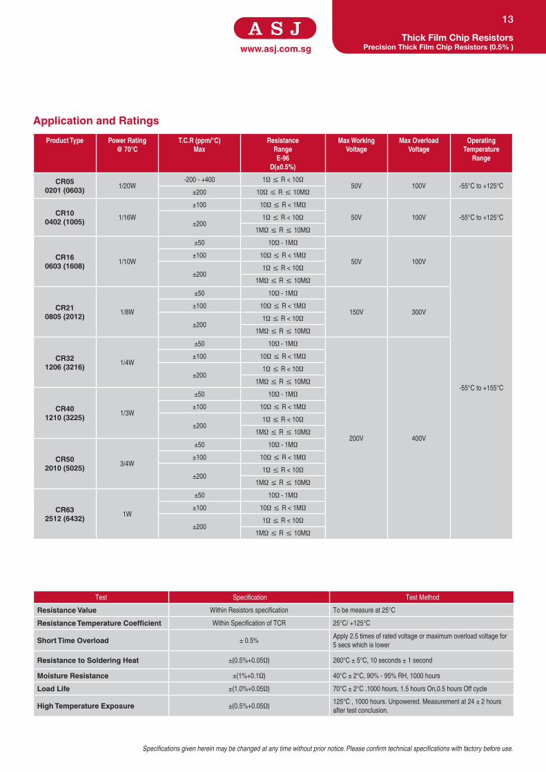
13
Product Type Power Rating @ 70°C
T.C.R (ppm/°C) Max
ResistanceRangeE-96
D(±0.5%)
Max Working Voltage
Max Overload Voltage
Operating Temperature
Range
CR050201 (0603)
1/20W
-200 - +400 1Ω ≤ R < 10Ω
50V 100V -55°C to +125°C
±200 10Ω ≤ R ≤ 10MΩ
CR10 0402 (1005)
1/16W
±100 10Ω ≤ R < 1MΩ
50V 100V -55°C to +125°C
±200
1Ω ≤ R < 10Ω
1MΩ ≤ R ≤ 10MΩ
CR16 0603 (1608)
1/10W
±50 10Ω - 1MΩ
50V 100V
-55°C to +155°C
±100 10Ω ≤ R < 1MΩ
±200
1Ω ≤ R < 10Ω
1MΩ ≤ R ≤ 10MΩ
CR21 0805 (2012)
1/8W
±50 10Ω - 1MΩ
150V 300V
±100 10Ω ≤ R < 1MΩ
±200
1Ω ≤ R < 10Ω
1MΩ ≤ R ≤ 10MΩ
CR32 1206 (3216)
1/4W
±50 10Ω - 1MΩ
200V 400V
±100 10Ω ≤ R < 1MΩ
±200
1Ω ≤ R < 10Ω
1MΩ ≤ R ≤ 10MΩ
CR40 1210 (3225)
1/3W
±50 10Ω - 1MΩ
±100 10Ω ≤ R < 1MΩ
±200
1Ω ≤ R < 10Ω
1MΩ ≤ R ≤ 10MΩ
CR50 2010 (5025)
3/4W
±50 10Ω - 1MΩ
±100 10Ω ≤ R < 1MΩ
±200
1Ω ≤ R < 10Ω
1MΩ ≤ R ≤ 10MΩ
CR63 2512 (6432)
1W
±50 10Ω - 1MΩ
±100 10Ω ≤ R < 1MΩ
±200
1Ω ≤ R < 10Ω
1MΩ ≤ R ≤ 10MΩ
Test Specification Test Method
Resistance Value Within Resistors specification To be measure at 25°C
Resistance Temperature Coefficient Within Specification of TCR 25°C/ +125°C
Short Time Overload ± 0.5%Apply 2.5 times of rated voltage or maximum overload voltage for
5 secs which is lower
Resistance to Soldering Heat ±(0.5%+0.05Ω) 260°C ± 5°C, 10 seconds ± 1 second
Moisture Resistance ±(1%+0.1Ω) 40°C ± 2°C, 90% - 95% RH, 1000 hours
Load Life ±(1.0%+0.05Ω) 70°C ± 2°C ,1000 hours, 1.5 hours On,0.5 hours Off cycle
High Temperature Exposure ±(0.5%+0.05Ω) 125°C , 1000 hours. Unpowered. Measurement at 24 ± 2 hours
after test conclusion.
Application and Ratings

www.asj.com.sg
Features
• Tolerance 1%, Temperature Coefficient of Resistance 50ppm/°C
• Excellent stability
• Halogen Free Epoxy
• Products with lead free terminations meet RoHs requirements
Dimensions and Construction
Ordering Code / Information
Thin Film Chip Resistors General Purpose Thin Film Chip Resistors
14
Dimensions
Type Inches (Millimeters)
L W H l1 l2
CT100402 (1005)
0.040 ± 0.004
(1.00 ± 0.10)
0.020 ± 0.002
(0.50 ± 0.05)
0.012 ± 0.002
(0.30 ± 0.05)
0.008 ± 0.004
(0.20 ± 0.10)
0.010 ± 0.004
(0.25 ± 0.10)
CT160603 (1608)
0.063 ± 0.004
(1.60 ± 0.10)
0.031 ± 0.004
(0.80 ± 0.10)
0.018 ± 0.004
(0.45 ± 0.10)
0.010 ± 0.006
(0.25 ± 0.15)
0.010 ± 0.006
(0.25 ± 0.15)
CT210805 (2012)
0.079 ± 0.004
(2.00 ± 0.10)
0.049 ± 0.004
(1.25 ± 0.10)
0.020 ± 0.004
(0.50 ± 0.10)
0.014 ± 0.008
(0.35 ± 0.20)
0.014 ± 0.008
(0.35 ± 0.20)
CT321206 (3216)
0.122 ± 0.004
(3.10 ± 0.10)
0.063 ± 0.004
(1.60 ± 0.10)
0.022 ± 0.004
(0.55 ± 0.10)
0.018 ± 0.008
(0.45 ± 0.20)
0.016 ± 0.008
(0.40 ± 0.20)
CT401210 (3225)
0.122 ± 0.004
(3.10 ± 0.10)
0.102 ± 0.006
(2.60 ± 0.15)
0.022 ± 0.004
(0.55 ± 0.10)
0.020 ± 0.008
(0.50 ± 0.20)
0.020 ± 0.008
(0.50 ± 0.20)
CT502010 (5025)
0.200 ± 0.004
(5.00 ± 0.10)
0.098 ± 0.006
(2.50 ± 0.15)
0.022 ± 0.004
(0.55 ± 0.10)
0.024 ± 0.008
(0.60 ± 0.20)
0.020 ± 0.008
(0.50 ± 0.2)
CT632512 (6432)
0.250 ± 0.004
(6.35 ± 0.10
0.126 ± 0.006
(3.20 ± 0.15)
0.022 ± 0.004
(0.55 ± 0.10)
0.024 ± 0.008
(0.60 ± 0.20)
0.020 ± 0.008
(0.50 ± 0.20)
CT 10 - XXXX - F K
Type Size(Inch / mm)
Nominal Resistance Resistance Tolerance
Packaging
General Purpose
Thin Film Chip
Resistors
10 (0402/1005)
16 (0603/1608)
21 (0805/2012)
32 (1206/3216)
40 (1210/3225)
50 (2010/5025)
63 (2512/6432)
Resistors 4-Digit E96 Series
10.2Ω=10R2
10KΩ=1002
F = ±1% E = 4,000 pcs Lead Free
L = 5,000 pcs Lead Free
K = 10,000 pcs Lead Free
160 180 200
120
-40 -20 200
40
60
120 14040 60 80 100
80
100
20
0
Temperature (˚C )
Rat
ed P
ower
(%)
125˚C
70˚C
-55˚C
(10,16,21,32,40,50,63)

Specifications given herein may be changed at any time without prior notice. Please confirm technical specifications with factory before use.
www.asj.com.sgThin Film Chip Resistors
General Purpose Thin Film Chip Resistors
15
Product Type Power Rating@ 70°C
T.C.R (ppm/°C) Max Resistance Range(E-96, E-24)
F(±1%)
Max Working Voltage
Max Overload Voltage Operating Temperature Range
CT100402 (1005)
1/16W ±50 10Ω - 121KΩ 50V 100V
-55°C to +125°C
CT160603(1608)
1/10W ±50 1Ω - 681KΩ 75V 150V
CT210805 (2012)
1/8W ±50 1Ω - 1.5MΩ 150V 300V
CT321206 (3216)
1/8W ±50 1Ω - 1.5MΩ
200V 400V
CT401210 (3225)
1/4W ±50 1Ω - 1MΩ
CT502010 (5025)
1/2W ±50 10Ω - 1MΩ
CT632512 (6432)
3/4W ±50 10Ω - 1MΩ
Test Specification Test Method
Resistance Value Within Resistors specification To be measure at 25°C
Resistance Temperature Coefficient Within Specification of TCR 25°C/ +125°C
Short Time Overload ± (0.5%+0.05Ω). No visible damageApply 2.5 times of rated voltage or maximum overload voltage for
5secs which is lower
Resistance to Soldering Heat ± (0.5%+0.05Ω). No visible damage 260°C ± 5°C, 10 seconds ± 1 second
Load Life ± (0.5%+0.05Ω) 70°C ± 2°C ,1000 hours, 1.5 hours On,0.5 hours Off cycle
High Temperature Exposure ± (0.5%+0.05Ω)125°C , 1000 hours. Unpowered. Measurement at 24 ± 2 hours
after test conclusion.
Application and Ratings

www.asj.com.sg
Features
• Precise Tolerance up to 0.05% and Low T.C.R down to 10ppm/°C
• Excellent stability
• Halogen Free Epoxy
• Products with lead free terminations meet RoHs requirements
Dimensions and Construction
Ordering Code / Information
Thin Film Chip Resistors Precision Thin Film Chip Resistors
16
Dimensions
Type Inches (Millimeters)
L W H l1 l2
CT100402 (1005)
0.040 ± 0.004
(1.00 ± 0.10)
0.020 ± 0.002
(0.50 ± 0.05)
0.012 ± 0.002
(0.30 ± 0.05)
0.008 ± 0.004
(0.20 ± 0.10)
0.010 ± 0.004
(0.25 ± 0.10)
CT160603 (1608)
0.063 ± 0.004
(1.60 ± 0.10)
0.031 ± 0.004
(0.80 ± 0.10)
0.018 ± 0.004
(0.45 ± 0.10)
0.010 ± 0.006
(0.25 ± 0.15)
0.010 ± 0.006
(0.25 ± 0.15)
CT210805 (2012)
0.079 ± 0.004
(2.00 ± 0.10)
0.049 ± 0.004
(1.25 ± 0.10)
0.020 ± 0.004
(0.50 ± 0.10)
0.014 ± 0.008
(0.35 ± 0.20)
0.014 ± 0.008
(0.35 ± 0.20)
CT321206 (3216)
0.122 ± 0.004
(3.10 ± 0.10)
0.063 ± 0.004
(1.60 ± 0.10)
0.022 ± 0.004
(0.55 ± 0.10)
0.018 ± 0.008
(0.45 ± 0.20)
0.016 ± 0.008
(0.40 ± 0.20)
CT401210 (3225)
0.122 ± 0.004
(3.10 ± 0.10)
0.102 ± 0.006
(2.60 ± 0.15)
0.022 ± 0.004
(0.55 ± 0.10)
0.020 ± 0.008
(0.50 ± 0.20)
0.020 ± 0.008
(0.50 ± 0.20)
CT502010 (5025)
0.200 ± 0.004
(5.00 ± 0.10)
0.098 ± 0.006
(2.50 ± 0.15)
0.022 ± 0.004
(0.55 ± 0.10)
0.024 ± 0.008
(0.60 ± 0.20)
0.020 ± 0.008
(0.50 ± 0.2)
CT632512 (6432)
0.250 ± 0.004
(6.35 ± 0.10
0.126 ± 0.006
(3.20 ± 0.15)
0.022 ± 0.004
(0.55 ± 0.10)
0.024 ± 0.008
(0.60 ± 0.20)
0.020 ± 0.008
(0.50 ± 0.20)
CT 10 - XXXX - F K - E
Type Size(Inch / mm)
Nominal Resistance Resistance Tolerance
Packaging T.C.R (ppm/°C)
Precision Thin
Film Chip
Resistors
10 (0402/1005)
16 (0603/1608)
21 (0805/2012)
32 (1206/3216)
40 (1210/3225)
50 (2010/5025)
63 (2512/6432)
Resistors 4-Digit E24 & E96
Series
10.2Ω=10R2
10KΩ=1002
A = ±0.05%
B = ±0.1%
C = ±0.25%
D = ±0.5%
E = 4,000 pcs Lead Free
L = 5,000 pcs Lead Free
K = 10,000 pcs Lead Free
B = ±10
C = ±15
D = ±25
E = ±50
160 180 200
120
-40 -20 200
40
60
120 14040 60 80 100
80
100
20
0
Temperature (˚C )
Rat
ed P
ower
(%)
125˚C
70˚C
-55˚C
(10,16,21,32,40,50,63)

Specifications given herein may be changed at any time without prior notice. Please confirm technical specifications with factory before use.
www.asj.com.sgThin Film Chip Resistors
Precision Thin Film Chip Resistors
17
Product Type Power Rating @ 70°C
T.C.R (ppm/°C) Max
Resistance Range(E-96, E-24)
Max Working Voltage
Max Overload Voltage
Operating Temperature
RangeA(±0.05%) B(±0.1%) C(±0.25%) D(±0.5%)
CT100402 (1005)
1/16W
±50
-
10Ω - 121KΩ 10Ω -121KΩ 10Ω -121KΩ
50V 100V
-55°C to
+125°C
±25 10Ω - 121KΩ 10Ω -121KΩ 10Ω -121KΩ
±15 10Ω - 100KΩ 10Ω - 100KΩ
-
±10 10Ω - 100KΩ 10Ω - 100KΩ
CT160603 (1608)
1/10W
±50 - 10Ω - 681KΩ 1Ω - 681KΩ 1Ω - 681KΩ
75V 150V
±25 1KΩ - 47KΩ 10Ω - 681KΩ 10Ω - 681KΩ 10Ω - 681KΩ
±15 1KΩ - 47KΩ 10Ω - 100KΩ 10Ω - 100KΩ
-
±10 1KΩ - 47KΩ 10Ω - 100KΩ 10Ω - 100KΩ
CT210805 (2012)
1/8W
±50 - 10Ω - 1.5MΩ 1Ω - 1.5MΩ 1Ω - 1.5MΩ
150V 300V
±25 100Ω - 100KΩ 10Ω - 1.5MΩ 10Ω - 1.5MΩ 10Ω - 1.5MΩ
±15 100Ω - 100KΩ 10Ω - 100KΩ 10Ω - 100KΩ
-
±10 100Ω - 100KΩ 10Ω - 100KΩ 10Ω - 100KΩ
CT321206 (3216)
1/8W
±50 - 10Ω - 1.5MΩ 1Ω - 1.5MΩ 1Ω - 1.5MΩ
200V 400V
±25 100Ω - 100KΩ 10Ω - 1.5MΩ 10Ω - 1.5MΩ 10Ω - 1.5MΩ
±15 100Ω - 100KΩ 10Ω - 100KΩ 10Ω - 100KΩ
-
±10 100Ω - 100KΩ 10Ω - 100KΩ 10Ω - 100KΩ
CT401210 (3225)
1/4W
±50 - 10Ω - 1MΩ 1Ω - 1MΩ 1Ω - 1MΩ
±25 100Ω - 100KΩ 10Ω - 1MΩ 10Ω - 1MΩ 10Ω - 1MΩ
±15 100Ω - 100KΩ 10Ω - 100KΩ 10Ω - 100KΩ
-
±10 100Ω - 100KΩ 10Ω - 100KΩ 10Ω - 100KΩ
CT502010 (5025)
1/2W
±50 - 10Ω - 1MΩ 10Ω - 1MΩ 10Ω - 1MΩ
±25 100Ω - 100KΩ 10Ω - 1MΩ 10Ω - 1MΩ 10Ω - 1MΩ
±15 100Ω - 100KΩ 10Ω - 100KΩ 10Ω - 100KΩ
-
±10 100Ω - 100KΩ 10Ω - 100KΩ 10Ω - 100KΩ
CT632512 (6432)
3/4W
±50 - 10Ω - 1MΩ 10Ω - 1MΩ 10Ω - 1MΩ
±25 100Ω - 100KΩ 10Ω - 1MΩ 10Ω - 1MΩ 10Ω - 1MΩ
±15 100Ω - 100KΩ 10Ω - 100KΩ 10Ω - 100KΩ
-
±10 100Ω - 100KΩ 10Ω - 100KΩ 10Ω - 100KΩ
Test Specification Test Method
Resistance Value Within Resistors specification To be measure at 25°C
Resistance Temperature Coefficient Within Specification of TCR 25°C/ +125°C
Short Time Overload ± (0.5%+0.05Ω). No visible damageApply 2.5 times of rated voltage or maximum overload voltage for
5 secs which is lower
Resistance to Soldering Heat ± (0.5%+0.05Ω). No visible damage 260°C ± 5°C, 10 seconds ± 1 second
Load Life ± (0.5%+0.05Ω) 70°C ± 2°C ,1000 hours, 1.5 hours On,0.5 hours Off cycle
High Temperature Exposure ± (0.5%+0.05Ω)125°C , 1000 hours. Unpowered. Measurement at 24 ± 2 hours
after test conclusion.
Application and Ratings
www.asj.com.sgwww.asj.com.sg
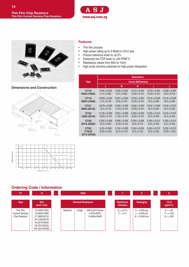
Features
• Thin film process
• High power rating up to 3 Watts in 2512 size
• Precise tolerance down to ±0.5%
• Extremely low TCR down to ±50 PPM/˚C
• Resistance values from 50m to 1ohm
• High purity alumina substrate for high power dissipation
Dimensions and Construction
Ordering Code / Information
Thin Film Chip ResistorsThin Film Current Sensing Chip Resistors
18
200
120
-40 -20 200
40
60
80
100
20
0160 180120 14040 60 80 100
Temperature ( C )
Rat
ed P
ower
(%)
155
70
-55 C
(10,16,21,32,50,63 , 633)
Dimensions
Type Inches (Millimeters)
L W H l1 l2
CT10 0402 (1005)
0.040 ± 0.002
(1.0 ± 0.05)
0.020 ± 0.002
(0.5 ± 0.05)
0.014 ± 0.004
(0.32 ± 0.10)
0.010 ± 0.004
(0.25 ± 0.10)
0.008 ± 0.004
(0.2 ± 0.10)
CT160603 (1608)
0.063 ± 0.004
(1.6 ± 0.10)
0.031 ± 0.004
(0.8 ± 0.10)
0.018 ± 0.004
(0.45 ± 0.10)
0.012 ± 0.008
(0.3 ± 0.20)
0.012 ± 0.008
(0.3 ± 0.20)
CT210805 (2012)
0.079 ± 0.006
(2.0 ± 0.15)
0.049 ± 0.006
(1.25 ± 0.15)
0.022 ± 0.004
(0.55 ± 0.10)
0.012 ± 0.008
(0.3 ± 0.20)
0.016 ± 0.010
(0.4 ± 0.25)
CT321206 (3216)
0.120 ± 0.006
(3.05 ± 0.15)
0.061 ± 0.006
(1.55 ± 0.15)
0.022 ± 0.004
(0.55 ± 0.10)
0.020 ± 0.012
(0.5 ± 0.30)
0.016 ± 0.010
(0.4 ± 0.25)
CT502010 (5025)
0.200 ± 0.008
(5.0 ± 0.20)
0.096 ± 0.006
(2.45 ± 0.15)
0.024 ± 0.006
(0.6 ± 0.15)
0.024 ± 0.012
(0.6 ± 0.30)
0.020 ± 0.010
(0.5 ± 0.25)
CT63CT633
2512 (6432)
0.25 ± 0.008
(6.35 ± 0.20)
0.124 ± 0.006
(3.15 ± 0.15)
0.024 ± 0.004
(0.6 ± 0.10)
0.024 ± 0.012
(0.6 ± 0.30)
0.022 ± 0.010
(0.55 ± 0.25)
CT 10 - R500 - F K - E
Type Size(Inch / mm)
Nominal Resistance Resistance Tolerance
Packaging T.C.R(ppm/˚C)
Thin Film
Current Sensing
Chip Resistors
10 (0402/1005)
16 (0603/1608)
21 (0805/2012)
32 (1206/3216)
50 (2010/5025)
63 (2512/6432)
633 (2512/6432)
Resistors 4-Digit E96 & E24 Series
0.47Ω=R470
0.499Ω=R499
D = ±0.5%
F = ±1%
E = 4,000 pcs
L = 5,000 pcs
K = 10,000 pcs
E = ± 50
F = ± 100
G = ± 200

Specifications given herein may be changed at any time without prior notice. Please confirm technical specifications with factory before use.
www.asj.com.sgThin Film Chip Resistors
Thin Film Current Sensing Chip Resistors
19
Product Type Power Rating@ 70°C
T.C.R (ppm/°C) Max
Resistance Range Maximum Working Voltage
Maximum Overload Voltage
Operating Temperature RangeD(±0.5%) F(±1%)
CT100402 (1005)
1/16W ±50, ±100 0.5Ω ≤ R < 1Ω
√(P*R) 2.5*√(P*R) -55°C + 155°C
CT160603 (1608)
1/10W
±100 0.2Ω - 0.3Ω
±50 0.301Ω ≤ R < 1Ω
CT210805 (2012)
1/8W
±100 0.2Ω - 0.3Ω
±50 0.301Ω ≤ R < 1Ω
CT321206 (3216)
1/4W
±200 - 0.05Ω - 0.1Ω
±100 0.101Ω - 0.3Ω
±50 0.301Ω ≤ R < 1Ω
CT50 2010 (5025)
3/4W
±200 0.05Ω - 0.1Ω
±100 0.101Ω - 0.3Ω
CT63 2512 (6432)
1W
±50 0.301Ω ≤ R < 1Ω
CT633 2512 (6432)
2W ±100 - 0.1Ω ≤ R < 1Ω
Test Specification Test Method
Resistance Value Within Resistors specification To be measure at 25°C
Resistance Temperature Coefficient As Spec. As Spec. +25/-55/+25/+125/+25°C
Short Time Overload ±1% RCWV*2.5 or Max. overload voltage for 5 seconds
Insulation Resistance >1000MΩ Apply 100VDC for 1 minute
Endurance ±1% 70 ± 2°C, Max. working voltage for 1000 hrs with 1.5 hrs
“ON” and 0.5 hrs “OFF”
Damp Heat with Load ±0.5%40 ± 2°C, 90 ~ 95% R.H. Max. working voltage for 1000 hrs
with 1.5 hrs “ON” and 0.5 hrs “OFF”
Bending Strength As Spec. Bending amplitude 3mm for 10 seconds
Solderability 95% min. coverage 245 ± 5°C for 3 seconds
Resistance to Soldering Heat ±0.5% 260 ± 5°C for 10 seconds
Dielectric Withstand Voltage By Type Apply Max. Overload Voltage for 1 minute
Thermal Shock ±0.5% -55°C ~150°C, 100 cycles
Low Temperature Operation ±0.5% 1 hour, -65°C followed by 45 minutes of RCWV
Application and Ratings

www.asj.com.sg
Features
• Resistance Range: 0.1Ω to less than 1Ω
• Highly reliable multi-layer electrode construction.
• Compatible with wave and reflow soldering process.
• Pb-Free with reflow soldering backward compatibility
Dimensions and Construction
Ordering Code / Information
Current Sensing Chip ResistorsMilli Ohm Thick Film Chip Resistors
20
Dimensions
Type Inches (Millimeters)
L W H l1 l2
CR100402 (1005)
0.040±0.004
(1.00±0.10)
0.020±0.002
(0.50±0.05)
0.014±0.002
(0.35±0.05)
0.008±0.004
(0.20±0.10)
0.010±0.004
(0.25±0.10)
CR160603 (1608)
0.063±0.004
(1.60±0.10)
0.031±0.004
(0.80±0.10)
0.018±0.004
(0.45±0.10)
0.012±0.008
(0.30±0.20)
0.012±0.008
(0.30±0.20)
CR210805 (2012)
0.079±0.006
(2.00±0.15)
0.049±0.004
(1.25±0.10)
0.020±0.004
(0.50±0.10)
0.016±0.008
(0.40±0.20)
0.016±0.008
(0.40±0.20)
CR321206 (3216)
0.122±0.004
(3.10±0.10)
0.063±0.006
(1.60±0.15)
0.022±0.002
(0.55±0.05)
0.020±0.010
(0.50±0.25)
0.020±0.010
(0.50±0.25)
CR401210 (3225)
0.122±0.004
(3.10±0.10)
0.098±0.006
(2.50±0.15)
0.022±0.002
(0.55±0.05)
0.020±0.010
(0.50±0.25)
0.016±0.008
(0.40±0.20)
CR502010 (5025)
0.200±0.006
(5.00±0.15)
0.098±0.006
(2.50±0.15)
0.022±0.002
(0.55±0.05)
0.024±0.010
(0.60±0.25)
0.016±0.008
(0.40±0.20)
CR632512 (6432)
0.250±0.006
(6.30±0.15)
0.126±0.006
(3.20±0.15)
0.022±0.002
(0.55±0.05)
0.024±0.010
(0.60±0.25)
0.016±0.008
(0.40±0.20)
CR 10 - RXXX - F K
Type Size (Inch / mm)
Nominal Resistance Resistance Tolerance
Packaging
Milli Ohm Thick
Film Chip Resistors
10 (0402/1005)
16 (0603/1608)
21 (0805/2012)
32 (1206/3216)
40 (1210/3225)
50 (2010/5025)
63 (2512/6432)
Resistors 4-Digit E96 & E24 Series
0.47Ω=R470
0.499Ω=R499
F = ± 1%
G = ± 2%
J = ± 5%
E = 4,000 pcs Lead Free
L = 5,000 pcs Lead Free
K = 10,000 pcs Lead Free
Y = 20,000 pcs Lead Free
20
0160 180120 140 002001080604
120
-40 -20 200
40
60
80
100
Temperature (˚C)
Rat
ed P
ower
(%
)
125˚C 155˚C
70˚C
-55˚C
(16,21,32,40,50,63)
(10)

Specifications given herein may be changed at any time without prior notice. Please confirm technical specifications with factory before use.
www.asj.com.sgCurrent Sensing Chip Resistors
Milli Ohm Thick Film Chip Resistors
21
Product Type Power Rating @ 70°C
T.C.R (ppm/°C) Max
ResistanceRange
E-96, E-24F(±1%)
ResistanceRangeE-24
G(±2%), J(±5%)
Max Working Voltage
Max Overload Voltage
Operating Temperature Range
CR10 0402 (1005)
1/16W ±200 0.1Ω ≤ R < 1Ω 0.1Ω ≤ R < 1Ω
50V 100V
-55°C to +125°C
CR160603 (1608)
1/10W ±200 0.1Ω ≤ R < 1Ω 0.1Ω ≤ R < 1Ω
-55°C to +155°C
CR210805 (2012)
1/8W
±100 0.1Ω ≤ R < 1Ω -
150V 300V
±200 - 0.1Ω ≤ R < 1Ω
CR321206 (3216)
1/4W
±100 0.1Ω ≤ R < 1Ω -
200 400V
±200 - 0.1Ω ≤ R < 1Ω
CR401210 (3225)
1/3W
±100 0.1Ω ≤ R < 1Ω -
±200 - 0.1Ω ≤ R < 1Ω
CR502010 (5025)
3/4W
±100 0.1Ω ≤ R < 1Ω -
±200 - 0.1Ω ≤ R < 1Ω
CR632512 (6432)
1W
±100 0.1Ω ≤ R < 1Ω -
±200 - 0.1Ω ≤ R < 1Ω
Test Specification Test Method
Resistance Value Within Resistors specification To be measure at 25°C
Resistance Temperature Coefficient Within Specification of TCR 25°C/ +125°C
Short Time Overload ±1.0% For 2% & 5% tolerance Apply 2.5 times of rated voltage or maximum overload voltage for
5secs which is lower
Resistance to Soldering Heat±(0.5%+0.05Ω) For 1% tolerance
260°C ± 5°C, 10 seconds ± 1 second
±(1.0%+0.05Ω) For 2% & 5% tolerance
Moisture Resistance ±(1%+0.1Ω) for 1% , 2% & 5% tolerance resistor 40°C ± 2°C, 90% - 95% RH, 1000 hours
Load Life±(1.0%+0.05Ω) For 1% tolerance
70°C ± 2°C ,1000 hours, 1.5 hours On,0.5 hours Off cycle
±(2.0%+0.1Ω) For 2% & 5% tolerance
High Temperature Exposure±(0.5%+0.05Ω) For 1% tolerance
125°C , 1000 hours. Unpowered. Measurement at 24 ± 2 hours
after test conclusion.±(1.0%+0.05Ω) For 2% & 5% tolerance
Application and Ratings

www.asj.com.sg
Features
• Resistance Range: 0.01Ω - 0.1Ω
• Highly reliable multi-layer electrode construction.
• Compatible with wave and reflow soldering process.
• Pb-Free with reflow soldering backward compatibility
Dimensions and Construction
Ordering Code / Information
Current Sensing Chip ResistorsUltra Low Ohmic Thick Film Chip Resistors
22
20
0160 180120 140 002001080604
120
-40 -20 200
40
60
80
100
Temperature (˚C)
Rat
ed P
ower
(%
)
125˚C 155˚C
70˚C
-55˚C
(16,21,32,40,50,63)
(10)
Dimensions
Type Inches (Millimeters)
L W H l1 l2
CR100402 (1005)
0.040±0.004
(1.00±0.10)
0.020±0.002
(0.50±0.05)
0.014±0.002
(0.35±0.05)
0.008±0.004
(0.20±0.10)
0.010±0.004
(0.25±0.10)
CR160603 (1608)
0.063±0.004
(1.60±0.10)
0.031±0.004
(0.80±0.10)
0.018±0.004
(0.45±0.10)
0.012±0.008
(0.30±0.20)
0.012±0.008
(0.30±0.20)
CR210805 (2012)
0.079±0.006
(2.00±0.15)
0.049±0.004
(1.25±0.10)
0.020±0.004
(0.50±0.10)
0.016±0.008
(0.40±0.20)
0.016±0.008
(0.40±0.20)
CR321206 (3216)
0.122±0.004
(3.10±0.10)
0.063±0.006
(1.60±0.15)
0.022±0.002
(0.55±0.05)
0.020±0.010
(0.50±0.25)
0.020±0.010
(0.50±0.25)
CR401210 (3225)
0.122±0.004
(3.10±0.10)
0.098±0.006
(2.50±0.15)
0.022±0.002
(0.55±0.05)
0.020±0.010
(0.50±0.25)
0.016±0.008
(0.40±0.20)
CR502010 (5025)
0.200±0.006
(5.00±0.15)
0.098±0.006
(2.50±0.15)
0.022±0.002
(0.55±0.05)
0.024±0.010
(0.60±0.25)
0.016±0.008
(0.40±0.20)
CR632512 (6432)
0.250±0.006
(6.30±0.15)
0.126±0.006
(3.20±0.15)
0.022±0.002
(0.55±0.05)
0.024±0.010
(0.60±0.25)
0.016±0.008
(0.40±0.20)
CR 32 - RXXX - HTC - F L
Type Size(Inch / mm)
Nominal Resistance Option Resistance Tolerance
Packaging
Ultra Low
Ohmic Thick
Film Chip
Resistors
10 (0402/1005)
16 (0603/1608)
21 (0805/2012)
32 (1206/3216)
40 (1210/3225)
50 (2010/5025)
63 (2512/6432)
Resistors 4-Digit E96 & E24
Series
0.091Ω=R091
0.03Ω=R030
HTC = High
Temperature
Coefficient
(Only applicable for
selection of resistance
range between 0.01Ω
≤ x 0.03Ω with
T.C.R of ±1,500ppm)
F = ±1%
G = ±2%
J = ±5%
E = 4,000 pcs Lead Free
L = 5,000 pcs Lead Free
K = 10,000 pcs Lead Free
Y = 20,000 pcs Lead Free

Specifications given herein may be changed at any time without prior notice. Please confirm technical specifications with factory before use.
www.asj.com.sgCurrent Sensing Chip Resistors
Ultra Low Ohmic Thick Film Chip Resistors
23
Product Type Power Rating @ 70°C
T.C.R (ppm/°C) Max
ResistanceRange
E-96, E-24F(±1%)
ResistanceRangeE-24
G(±2%), J(±5%)
Max Working Voltage
Max Overload Voltage
Operating Temperature Range
CR10 0402 (1005)
1/16W
±200 0.04Ω ≤ R < 0.1Ω 50V 100V
-55°C to +125°C
CR16 0603 (1608)
1/10W
-55°C to +155°C
CR21 0805 (2012)
1/8W ±200 0.03Ω ≤ R < 0.1Ω 150V 300V
CR32 1206 (3216)
1/4W
±200 0.03Ω ≤ R < 0.1Ω
200V 400V
±100
0.01Ω ≤ R < 0.03Ω
±1500
CR40 1210 (3225)
1/3W
±100 0.03Ω ≤ R < 0.1Ω -
±200 - 0.03Ω ≤ R < 0.1Ω
±1500 0.01Ω ≤ R < 0.03Ω
CR50 2010 (5025)
3/4W
±100 0.01Ω ≤ R < 0.1Ω -
±200 - 0.01Ω ≤ R < 0.1Ω
±1500 0.01Ω ≤ R < 0.03Ω
CR63 2512 (6432)
1W
±100 0.03Ω ≤ R < 0.1Ω -
±200 - 0.03Ω ≤ R < 0.1Ω
±1500 0.01Ω ≤ R < 0.03Ω
Test Specification Test Method
Resistance Value Within Resistors specification To be measure at 25°C
Resistance Temperature Coefficient Within Specification of TCR 25°C/ +125°C
Short Time Overload± 0.5% For 1% tolerance Apply 2.5 times of rated voltage or maximum
overload voltage for 5secs which is lower±1.0% For 2% & 5% tolerance
Resistance to Soldering Heat±(0.5%+0.05Ω) For 1% tolerance
260°C ± 5°C, 10 seconds ± 1 second±(1.0%+0.05Ω) For 2% & 5% tolerance
Moisture Resistance±(1%+0.1Ω) for 1% , 2% & 5% tolerance resistor
40°C ± 2°C, 90% - 95% RH, 1000 hours
Load Life±(1.0%+0.05Ω) For 1% tolerance 70°C ± 2°C ,1000 hours, 1.5 hours On,0.5 hours
Off cycle±(2.0%+0.1Ω) For 2% & 5% tolerance
High Temperature Exposure±(0.5%+0.05Ω) For 1% tolerance 125°C , 1000 hours. Unpowered. Measurement at
24 ± 2 hours after test conclusion.±(1.0%+0.05Ω) For 2% & 5% tolerance
Application and Ratings

www.asj.com.sg
Features
• Resistance Range: 0.01Ω to less than 1Ω
• Highly reliable multi-layer electrode construction.
• Compatible with wave and reflow soldering process.
• Pb-Free with reflow soldering backward compatibility
Dimensions and Construction
Ordering Code / Information
Current Sensing Chip ResistorsLow Ohmic High PowerCurrent Sensing Chip Resistors
24
20
0160 180120 140 002001080604
120
-40 -20 200
40
60
80
100
Temperature (˚C)
Rat
ed P
ower
(%
)
125˚C 155˚C
70˚C
-55˚C
(16,21,32,40,50,63)
(10)
Dimensions
Type Inches (Millimeters)
L W H l1 l2
CLP100402 (1005)
0.040±0.004
(1.00±0.10)
0.020±0.002
(0.50±0.05)
0.014±0.002
(0.35±0.05)
0.008±0.004
(0.20±0.10)
0.010±0.004
(0.25±0.10)
CLP160603 (1608)
0.063±0.004
(1.60±0.10)
0.031±0.004
(0.80±0.10)
0.018±0.004
(0.45±0.10)
0.012±0.008
(0.30±0.20)
0.012±0.008
(0.30±0.20)
CLP210805 (2012)
0.079±0.006
(2.00±0.15)
0.049±0.004
(1.25±0.10)
0.020±0.004
(0.50±0.10)
0.016±0.008
(0.40±0.20)
0.016±0.008
(0.40±0.20)
CLP321206 (3216)
0.122±0.004
(3.10±0.10)
0.063±0.006
(1.60±0.15)
0.022±0.002
(0.55±0.05)
0.020±0.010
(0.50±0.25)
0.020±0.010
(0.50±0.25)
CLP401210 (3225)
0.122±0.004
(3.10±0.10)
0.098±0.006
(2.50±0.15)
0.022±0.002
(0.55±0.05)
0.020±0.010
(0.50±0.25)
0.016±0.008
(0.40±0.20)
CLP502010 (5025)
0.200±0.006
(5.00±0.15)
0.098±0.006
(2.50±0.15)
0.022±0.002
(0.55±0.05)
0.024±0.010
(0.60±0.25)
0.016±0.008
(0.40±0.20)
CLP632512 (6432)
0.250±0.006
(6.30±0.15)
0.126±0.006
(3.20±0.15)
0.022±0.002
(0.55±0.05)
0.024±0.010
(0.60±0.25)
0.016±0.008
(0.40±0.20)
CLP 10 - RXXX - HTC - F K
Type Size(Inch / mm)
Nominal Resistance Option Resistance Tolerance
Packaging
Low Ohmic
High Power
Current
Sensing Chip
Resistors
10 (0402/1005)
16 (0603/1608)
21 (0805/2012)
32 (1206/3216)
40 (1210/3225)
50 (2010/5025)
63 (2512/6432)
Resistors 4-Digit E24 & E96
Series
0.47Ω=R470
0.499Ω=R499
HTC = High
Temperature
Coefficient
(Only applicable
for selection of
resistance range
between 0.01Ω
≤ x 0.03Ω
with T.C.R of
±1,500ppm)
F = ±1%
G = ±2%
J = ±5%
E = 4,000 pcs Lead Free
L = 5,000 pcs Lead Free
K = 10,000 pcs Lead Free
Y = 20,000 pcs Lead Free

Specifications given herein may be changed at any time without prior notice. Please confirm technical specifications with factory before use.
www.asj.com.sg
Current Sensing Chip ResistorsLow Ohmic High Power
Current Sensing Chip Resistors
25
Product Type Power Rating @ 70°C
T.C.R (ppm/°C) Max
ResistanceRange
E-96, E-24F(±1%)
ResistanceRangeE-24
G(±2%), J(±5%)
Max Working Voltage
Max Overload Voltage
Operating Temperature Range
CLP10 0402 (1005)
1/8W
±200 0.04Ω ≤ R < 0.1Ω 50V 100V
-55°C to +125°C
CLP16 0603 (1608)
1/5W
-55°C to +155°C
CLP21 0805 (2012)
1/4W ±200 0.03Ω ≤ R < 0.1Ω 150V 300V
CLP32 1206 (3216)
1/2W
±200 0.03Ω ≤ R < 0.1Ω
200V 400V
±100
0.01Ω ≤ R < 0.03Ω
±1500
CLP40 1210 (3225)
3/4W
±100 0.03Ω ≤ R < 0.1Ω -
±200 - 0.03Ω ≤ R < 0.1Ω
±1500 0.01Ω ≤ R < 0.03Ω
CLP50 2010 (5025)
1W
±100 0.01Ω ≤ R < 0.1Ω -
±200 - 0.01Ω ≤ R < 0.1Ω
±1500 0.01Ω ≤ R < 0.03Ω
CLP63 2512 (6432)
2W
±100 0.03Ω ≤ R < 0.1Ω -
±200 - 0.03Ω ≤ R < 0.1Ω
±1500 0.01Ω ≤ R < 0.03Ω
Test Specification Test Method
Resistance Value Within Resistors specification To be measure at 25°C
Resistance Temperature Coefficient Within Specification of TCR 25°C/ +125°C
Short Time Overload±0.5% For 1% tolerance
Apply 2.5 times of rated voltage or maximum overload voltage for 5secs
which is lower±1.0% For 2% & 5% tolerance
Resistance to Soldering Heat±(0.5%+0.05Ω) For 1% tolerance
260°C ± 5°C, 10 seconds ± 1 second
±(1.0%+0.05Ω) For 2% & 5% tolerance
Moisture Resistance ±(1%+0.1Ω) for 1% , 2% & 5% tolerance resistor 40°C ± 2°C, 90% - 95% RH, 1000 hours
Load Life±(1.0%+0.05Ω) For 1% tolerance
70°C ± 2°C ,1000 hours, 1.5 hours On,0.5 hours Off cycle
±(2.0%+0.1Ω) For 2% & 5% tolerance
High Temperature Exposure±(0.5%+0.05Ω) For 1% tolerance
125°C , 1000 hours. Unpowered. Measurement at 24 ± 2 hours after
test conclusion.±(1.0%+0.05Ω) For 2% & 5% tolerance
Application and Ratings

www.asj.com.sg
Features
• Robust metal strip able to withstand high temperature and high current
• Low TCR and Inductance
• Resistance range from 0.5mΩ to 15mΩ
• Designed for current sense circuits in power electronic systems
Dimensions and Construction
Ordering Code / Information
Current Sensing Chip ResistorsMetal Element Current Sensing Chip Resistors
26
Dimensions
Type Inches (Millimeters)
Resistance
Value L W T D
CLS321206 (3216)
0.001Ω - 0.01Ω0.126 ± 0.010
(3.20 ± 0.254)
0.063 ± 0.004
(1.60 ± 0.104)
0.024 ± 0.008
(0.60 ± 0.20)
0.039 ± 0.015
(0.98 ± 0.38)
CLS502010 (5025)
0.001Ω - 0.01Ω0.200 ± 0.010
(5.08 ± 0.254)
0.100 ± 0.006
(2.54 ± 0.15)
0.024 ± 0.008
(0.60 ± 0.20)
0.066 ± 0.025
(1.665 ± 0.625)
CLS632512 (6432)
0.0005Ω
0.250 ± 0.010
(6.35 ± 0.254)
0.125 ± 0.014
(3.18 ± 0.35)
0.024 ± 0.008
(0.60 ± 0.20)
0.105 ± 0.010
(2.675 ± 0.254)
0.00075Ω0.097 ± 0.010
(2.475 ± 0.254)
0.001Ω -
0.0015Ω
0.056 ± 0.010
(1.425 ± 0.254)
0.002Ω - 0.003Ω0.046 ± 0.010
(1.175 ± 0.254)
0.004Ω0.086 ± 0.010
(2.175 ± 0.254)
0.005Ω - 0.006Ω0.076 ± 0.010
(1.925 ± 0.254)
0.007Ω0.056 ± 0.010
(1.425 ± 0.254)
0.008Ω - 0.02Ω0.046 ± 0.010
(1.175 ± 0.254)
CLS 6325 - RXXX - F P
Type Size(Inch / mm)(Power Rating)
Nominal Resistance Resistance Tolerance
Packaging
Metal Element
Current Sensing Chip
Resistors
32 (1206/3216)(1W)
50 (2010/5025)(1.5W)
631 (2512/6432)(1W)
632 (2512/6432)(2W)
6325 (2512/6432)(2.5W)
633 (2512/6432)(3W)
Resistors 4-Digit E24 & E96 Series
0.0005Ω = R0005
0.001Ω = R001
F = ±1%
J = ±5%
P = 2,000 pcs
20
0160 180120 14040 60 80 100 200
120
-40 -20 200
40
60
80
100
Temperature (˚C )
Rat
ed P
ower
(%)
170˚C
70˚C-55˚C
(32,50,63)

Specifications given herein may be changed at any time without prior notice. Please confirm technical specifications with factory before use.
www.asj.com.sgCurrent Sensing Chip Resistors
Metal Element Current Sensing Chip Resistors
27
Product Type Coating Power Rating@ 80°C
T.C.R (ppm/°C) Max
ResistanceRange
E-96, E-24F(±1%), J(±5%)
Max Working Voltage
Max Overload Voltage
Operating Temperature Range
CLS321206 (3216)
Black 1W ±50 0.001Ω - 0.01Ω
√(P*R) 2.5*√(P*R) -55°C to +170°C
CLS502010 (5025)
Black 1.5W ±50 0.001Ω - 0.01Ω
CLS631CLS632CLS6325CLS633
2512 (6432)
Green
1W ±50 0.011Ω - 0.015Ω
2W ±50 0.0035Ω, 0.0065Ω - 0.01Ω
2.5W ±50 0.004Ω, 0.005Ω, 0.006Ω
3W
±50 0.001Ω - 0.003Ω
±100 0.0005Ω, 0.00075Ω
* Green Coating is only suitable for IR reflow soldering only
Test Specification Test Method
Resistance Value Within Resistors specification To be measure at 25°C
Resistance Temperature Coefficient Within Specification of TCR 25°C/ +125°C
Short Time Overload±0.5% Black coating
Apply 2.5 times of rated voltage or maximum overload voltage for
5secs which is lower±1.0% Green coating
Resistance to Soldering Heat±0.5% Black coating
260°C ± 5°C, 10 seconds ± 1 second
±1.0% Green coating
Load Life±1.0% Black coating
70°C ± 2°C ,1000 hours, 1.5 hours On,0.5 hours Off cycle
±1.0% Green coating
Thermal shock±0.5% Black coating
-55°C ~ 150°C, 100 cycles
±1.0% Green coating
Application and Ratings
www.asj.com.sg
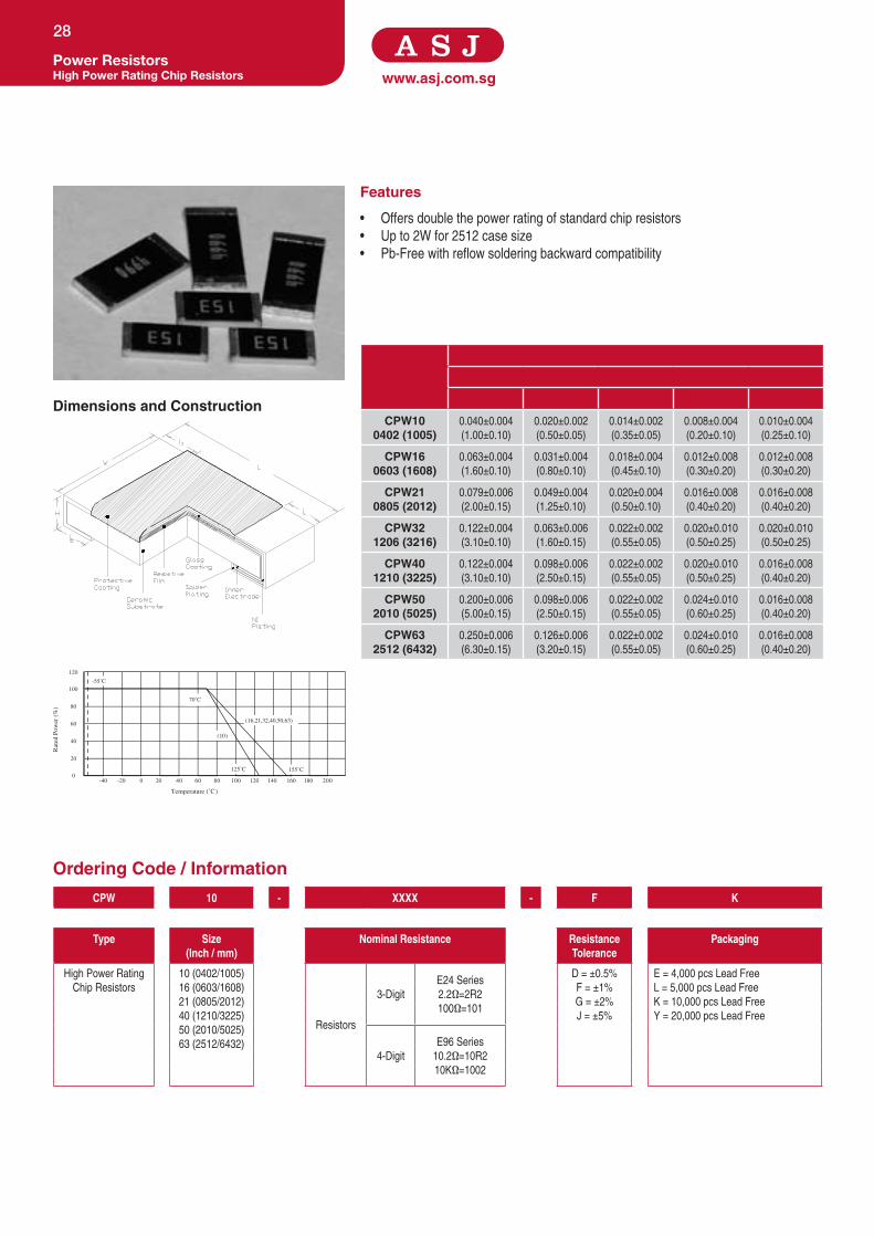
Features
• Offers double the power rating of standard chip resistors
• Up to 2W for 2512 case size
• Pb-Free with reflow soldering backward compatibility
CPW100402 (1005)
0.040±0.004
(1.00±0.10)
0.020±0.002
(0.50±0.05)
0.014±0.002
(0.35±0.05)
0.008±0.004
(0.20±0.10)
0.010±0.004
(0.25±0.10)
CPW160603 (1608)
0.063±0.004
(1.60±0.10)
0.031±0.004
(0.80±0.10)
0.018±0.004
(0.45±0.10)
0.012±0.008
(0.30±0.20)
0.012±0.008
(0.30±0.20)
CPW210805 (2012)
0.079±0.006
(2.00±0.15)
0.049±0.004
(1.25±0.10)
0.020±0.004
(0.50±0.10)
0.016±0.008
(0.40±0.20)
0.016±0.008
(0.40±0.20)
CPW321206 (3216)
0.122±0.004
(3.10±0.10)
0.063±0.006
(1.60±0.15)
0.022±0.002
(0.55±0.05)
0.020±0.010
(0.50±0.25)
0.020±0.010
(0.50±0.25)
CPW401210 (3225)
0.122±0.004
(3.10±0.10)
0.098±0.006
(2.50±0.15)
0.022±0.002
(0.55±0.05)
0.020±0.010
(0.50±0.25)
0.016±0.008
(0.40±0.20)
CPW502010 (5025)
0.200±0.006
(5.00±0.15)
0.098±0.006
(2.50±0.15)
0.022±0.002
(0.55±0.05)
0.024±0.010
(0.60±0.25)
0.016±0.008
(0.40±0.20)
CPW632512 (6432)
0.250±0.006
(6.30±0.15)
0.126±0.006
(3.20±0.15)
0.022±0.002
(0.55±0.05)
0.024±0.010
(0.60±0.25)
0.016±0.008
(0.40±0.20)
Dimensions and Construction
Ordering Code / Information
Power ResistorsHigh Power Rating Chip Resistors
28
CPW 10 - XXXX - F K
Type Size(Inch / mm)
Nominal Resistance Resistance Tolerance
Packaging
High Power Rating
Chip Resistors
10 (0402/1005)
16 (0603/1608)
21 (0805/2012)
40 (1210/3225)
50 (2010/5025)
63 (2512/6432)
Resistors
3-Digit
E24 Series
2.2Ω=2R2
100Ω=101
D = ±0.5%
F = ±1%
G = ±2%
J = ±5%
E = 4,000 pcs Lead Free
L = 5,000 pcs Lead Free
K = 10,000 pcs Lead Free
Y = 20,000 pcs Lead Free
4-Digit
E96 Series
10.2Ω=10R2
10KΩ=1002
20
0160 180120 140 002001080604
120
-40 -20 200
40
60
80
100
Temperature (˚C)
Rat
ed P
ower
(%
)
125˚C 155˚C
70˚C
-55˚C
(16,21,32,40,50,63)
(10)

Specifications given herein may be changed at any time without prior notice. Please confirm technical specifications with factory before use.
www.asj.com.sgPower Resistors
High Power Rating Chip Resistors
29
Product Type Power Rating @ 70°C
T.C.R (ppm/°C) Max
ResistanceRangeE-96
D(±0.5%)
ResistanceRange
E-96, E-24F(±1%)
ResistanceRangeE-24
G(±2%), J(±5%)
Max Working Voltage
Max Overload Voltage
Operating Temperature
Range
CPW10 0402 (1005)
1/8W
±200
0.1Ω ≤ R < 10Ω
50V 100V
-55°C to +125°C1MΩ ≤ R ≤ 15MΩ
±100 10Ω ≤ R < 1MΩ
CPW160603 (1608)
1/5W
±200
0.1Ω ≤ R < 10Ω
-55°C to +155°C
1MΩ ≤ R ≤ 15MΩ
±100 10Ω ≤ R < 1MΩ
CPW210805 (2012)
1/4W
±200
0.1Ω ≤ R < 10Ω
150V 300V1MΩ ≤ R ≤ 15MΩ
±100 10Ω ≤ R < 1MΩ
CPW321206 (3216)
1/2W
±200
0.1Ω ≤ R < 10Ω
200V 400V
1MΩ ≤ R ≤ 15MΩ
±100 10Ω ≤ R < 1MΩ
CPW40 1210 (3225)
2/3W
±200
0.1Ω ≤ R < 10Ω
1MΩ ≤ R ≤ 15MΩ
±100 10Ω ≤ R < 1MΩ
CPW502010 (5025)
1W
±200
0.1Ω ≤ R < 10Ω
1MΩ ≤ R ≤ 15MΩ
±100 10Ω ≤ R < 1MΩ
CPW632512 (6432)
2W
±200
0.1Ω ≤ R < 10Ω
1MΩ ≤ R ≤ 15MΩ
±100 10Ω ≤ R < 1MΩ
Test Specification Test Method
Resistance Value Within Resistors specification To be measure at 25°C
Resistance Temperature Coefficient Within Specification of TCR 25°C/ +125°C
Short Time Overload±0.5% For 1% tolerance
Apply 2.5 times of rated voltage or maximum overload voltage for
5 secs which is lower±1.0% For 2% & 5% tolerance
Resistance to Soldering Heat±(0.5%+0.05Ω) For 1% tolerance
260°C ± 5°C, 10 seconds ± 1 second
±(1.0%+0.05Ω) For 2% & 5% tolerance
Moisture Resistance ±(1%+0.1Ω) for 1% , 2% & 5% tolorence resistor 40°C ± 2°C, 90% - 95% RH, 1000 hours
Load Life±(1.0%+0.05Ω) For 1% tolerance
70°C ± 2°C ,1000 hours, 1.5 hours On,0.5 hours Off cycle
±(2.0%+0.1Ω) For 2% & 5% tolerance
High Temperature Exposure±(0.5%+0.05Ω) For 1% tolerance
125°C , 1000 hours. Unpowered. Measurement at 24 ± 2 hours
after test conclusion.±(1.0%+0.05Ω) For 2% & 5% tolerance
Application and Ratings

www.asj.com.sg
Features
• Higher maximum working voltage compared to standard chip resistors
• Reliable electrode construction
Dimensions and Construction
Ordering Code / Information
Power ResistorsMedium Voltage Chip Resistors
30
Dimensions
Type Inches (Millimeters)
L W H l1 l2
CPM210805 (2012)
0.079 ± 0.006
(2.00 ± 0.15)
0.049 ± 0.004
(1.25 ± 0.10)
0.020 ± 0.004
(0.50 ± 0.10)
0.016 ± 0.008
(0.40 ± 0.20)
0.016 ± 0.008
(0.40 ± 0.20)
CPM321206 (3216)
0.122 ± 0.004
(3.10 ± 0.10)
0.063 ± 0.006
(1.60 ± 0.15)
0.022 ± 0.004
(0.55 ± 0.10)
0.020 ± 0.010
(0.50 ± 0.25)
0.020 ± 0.010
(0.50 ± 0.25)
CPM632512 (6432)
0.250 ± 0.006
(6.30 ± 0.15)
0.126 ± 0.006
(3.20 ± 0.15)
0.022 ± 0.004
(0.55 ± 0.10)
0.024 ± 0.010
(0.60 ± 0.25)
0.016 ± 0.008
(0.40 ± 0.20)
CPM 21 - 1000 - F L
Type Size(Inch / mm) Nominal Resistance
Resistance Tolerance
Packaging
Medium Voltage Chip
Resistors
21 (0805/2012)
32 (1206/3216)
63 (2512/6432)
Resistors
3-DigitE24 Series
100KΩ=104
F = ±1%
J = ±5%
E = 4,000 pcs Lead Free
L = 5,000 pcs Lead Free
4-DigitE96 Series
100KΩ=1003
160 180 200
120
-40 -20 200
40
60
120 14040 60 80 100
80
100
20
0
Temperature (˚C )
Rat
ed P
ower
(%)
155˚C
70˚C
-55˚C
(21,32,63)

Specifications given herein may be changed at any time without prior notice. Please confirm technical specifications with factory before use.
www.asj.com.sgPower Resistors
Medium Voltage Chip Resistors
31
Product Type Power Rating @ 70°C
T.C.R (ppm/°C) Max
ResistanceRange
E-96, E-24F(±1%)
ResistanceRangeE-24
J(±5%)
Max Working Voltage
Max Overload Voltage
Dielectric Withstanding
Voltage
Operating Temperature Range
CPM210805 (2012)
1/8W
± 200
100KΩ to 10MΩ 400V 800V
-55°C to +155°CCPM32
1206 (3216)1/4W 100KΩ to 10MΩ 100KΩ to 27MΩ
500V 1,000V
CPM632512 (6432)
1W - 4.7MΩ to 16MΩ
Test Specification Test Method
Resistance Value Within Resistors specification To be measure at 25°C
Resistance Temperature Coefficient Within Specification of TCR 25°C/ +125°C
Short Time Overload±0.5% For 1% tolerance
Apply 2.5 times of rated voltage or maximum overload voltage for
5secs which is lower±1.0% For 2% & 5% tolerance
Resistance to Soldering Heat±(0.5%+0.05Ω) For 1% tolerance
260°C ± 5°C, 10 seconds ± 1 second
±(1.0%+0.05Ω) For 2% & 5% tolerance
Moisture Resistance ±(1%+0.1Ω) for 1% , 2% & 5% tolerance resistor 40°C ± 2°C, 90% - 95% RH, 1000 hours
Load Life±(1.0%+0.05Ω) For 1% tolerance
70°C ± 2°C ,1000 hours, 1.5 hours On,0.5 hours Off cycle
±(2.0%+0.1Ω) For 2% & 5% tolerance
High Temperature Exposure±(0.5%+0.05Ω) For 1% tolerance
125°C , 1000 hours. Unpowered. Measurement at 24 ± 2 hours
after test conclusion.±(1.0%+0.05Ω) For 2% & 5% tolerance
Application and Ratings

www.asj.com.sg
Features
• Highly reliable multilayer electrode construction
• Up to 3.0kV for 2512 case size
• Excellent performance at high voltage
• Suitable for inverters and camera flash circuits
Dimensions and Construction
Ordering Code / Information
Power ResistorsHigh Voltage Chip Resistors
32
200
120
-40 -20 200
40
60
80
100
20
0160 180120 14040 60 80 100
Temperature (˚C )
Rat
ed P
ower
(%)
125˚C
70˚C
-55˚C
(10,16,21,32,40,50,63)
Dimensions
Type Inches (Millimeters)
L W H I1 i2
CPH100402 (1005)
0.040 ± 0.004
(1.00 ± 0.05)
0.020 ± 0.002
(0.50 ± 0.0.05)
0.014 ± 0.002
(0.35 ± 0.05)
0.008 ± 0.004
(0.20 ± 0.10)
0.010 ± 0.004
(0.20 ± 0.10)
CPH160603 (1608)
0.063 ± 0.004
(1.60 ± 0.10)
0.031 ± 0.004
(0.80 ± 0.10)
0.018 ± 0.004
(0.45 ± 0.10)
0.012 ± 0.008
(0.30 ± 0.20)
0.012 ± 0.008
(0.30 ± 0.20)
CPH210805 (2012)
0.079 ± 0.006
(2.00 ± 0.10)
0.049 ± 0.004
(1.25 ± 0.10)
0.020 ± 0.004
(0.50 ± 0.10)
0.014 ± 0.008
(0.35 ± 0.20)
0.016 ± 0.008
(0.40 ± 0.20)
CPH321206 (3216)
0.122 ± 0.004
(3.10 ± 0.10)
0.061 ± 0.004
(1.55 ± 0.10)
0.022 ± 0.004
(0.55 ± 0.10)
0.020 ± 0.010
(0.50 ± 0.25)
0.020 ± 0.008
(0.50 ± 0.20)
CPH502010 (5025)
0.200 ± 0.008
(5.00 ± 0.20)
0.098 ± 0.006
(2.50 ± 0.15)0.024 ± 0.010
(0.60 ± 0.25)CPH632512 (6432)
0.25 ± 0.008
(6.35 ± 0.20)
0.126 ± 0.006
(3.20 ± 0.15)
CPH 10 - XXXX - F K
Type Size(Inch / mm)
Nominal Resistance Resistance Tolerance
Packaging
High Voltage Chip
Resistors
10 (0402/1005)
16 (0603/1608)
21 (0805/2012)
32 (1206/3216)
50 (2010/5025)
63 (2512/6432)
Resistors
3-Digit
E24 Series
10Ω=100
100Ω=101
F = ± 1%
J = ± 5%
E = 4,000 pcs Lead Free
L = 5,000 pcs Lead Free
K = 10,000 pcs Lead Free
4-Digit
E96 Series
10.2Ω=10R2
10KΩ=1002
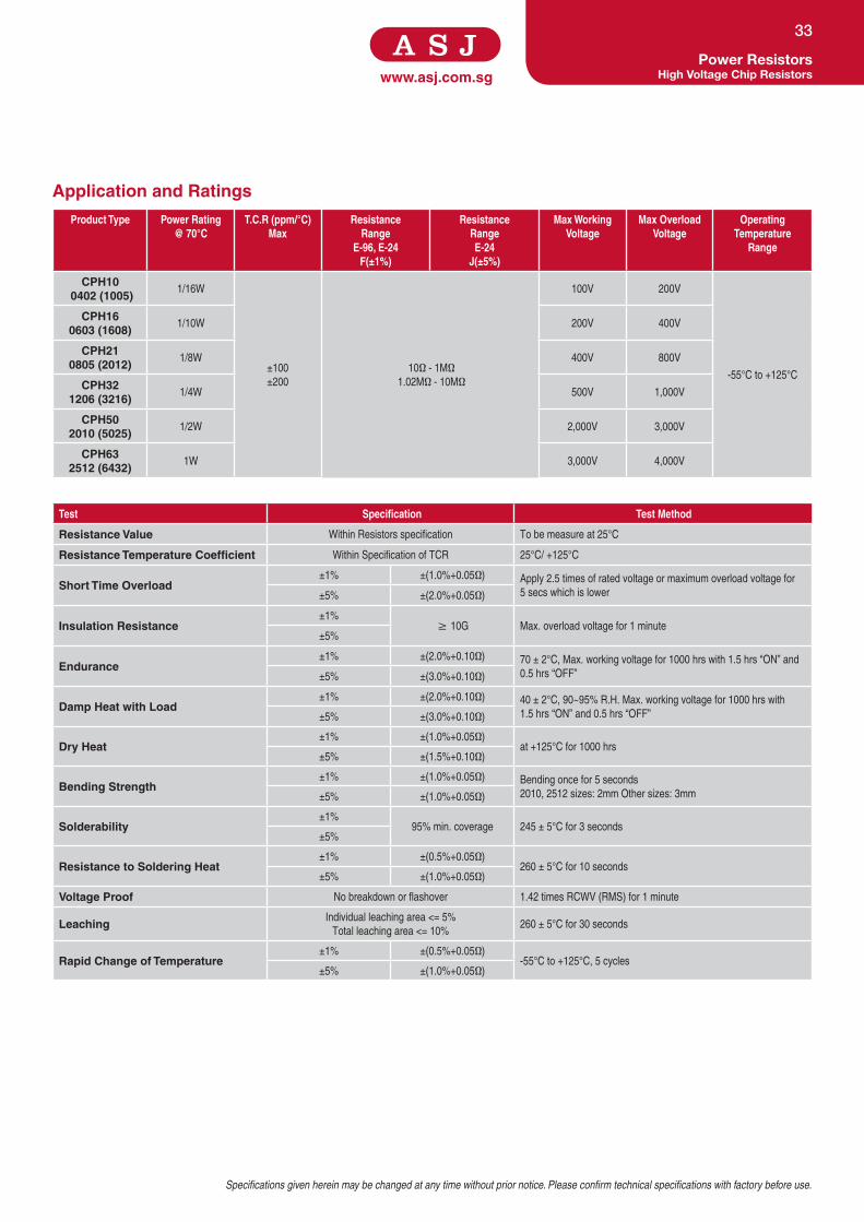
Specifications given herein may be changed at any time without prior notice. Please confirm technical specifications with factory before use.
www.asj.com.sgPower Resistors
High Voltage Chip Resistors
33
Product Type Power Rating @ 70°C
T.C.R (ppm/°C) Max
ResistanceRange
E-96, E-24F(±1%)
ResistanceRangeE-24
J(±5%)
Max Working Voltage
Max Overload Voltage
Operating Temperature
Range
CPH10 0402 (1005)
1/16W
±100
±200
10Ω - 1MΩ
1.02MΩ - 10MΩ
100V 200V
-55°C to +125°C
CPH160603 (1608)
1/10W 200V 400V
CPH210805 (2012)
1/8W 400V 800V
CPH321206 (3216)
1/4W 500V 1,000V
CPH502010 (5025)
1/2W 2,000V 3,000V
CPH632512 (6432)
1W 3,000V 4,000V
Test Specification Test Method
Resistance Value Within Resistors specification To be measure at 25°C
Resistance Temperature Coefficient Within Specification of TCR 25°C/ +125°C
Short Time Overload±1% ±(1.0%+0.05Ω)
Apply 2.5 times of rated voltage or maximum overload voltage for
5 secs which is lower±5% ±(2.0%+0.05Ω)
Insulation Resistance±1%
≥ 10G Max. overload voltage for 1 minute
±5%
Endurance±1% ±(2.0%+0.10Ω)
70 ± 2°C, Max. working voltage for 1000 hrs with 1.5 hrs “ON” and
0.5 hrs “OFF”±5% ±(3.0%+0.10Ω)
Damp Heat with Load±1% ±(2.0%+0.10Ω) 40 ± 2°C, 90~95% R.H. Max. working voltage for 1000 hrs with
1.5 hrs “ON” and 0.5 hrs “OFF”±5% ±(3.0%+0.10Ω)
Dry Heat±1% ±(1.0%+0.05Ω)
at +125°C for 1000 hrs
±5% ±(1.5%+0.10Ω)
Bending Strength±1% ±(1.0%+0.05Ω) Bending once for 5 seconds
2010, 2512 sizes: 2mm Other sizes: 3mm±5% ±(1.0%+0.05Ω)
Solderability±1%
95% min. coverage 245 ± 5°C for 3 seconds
±5%
Resistance to Soldering Heat±1% ±(0.5%+0.05Ω)
260 ± 5°C for 10 seconds
±5% ±(1.0%+0.05Ω)
Voltage Proof No breakdown or flashover 1.42 times RCWV (RMS) for 1 minute
LeachingIndividual leaching area <= 5%
Total leaching area <= 10%260 ± 5°C for 30 seconds
Rapid Change of Temperature±1% ±(0.5%+0.05Ω)
-55°C to +125°C, 5 cycles
±5% ±(1.0%+0.05Ω)
Application and Ratings

www.asj.com.sg
Features
• Resistance range - above 10MΩ to 100MΩ
• Highly reliable multilayer electrode construction
• Compatible with all soldering process
Dimensions and Construction
Ordering Code / Information
High Ohmic Chip ResistorsHigh Ohmic Value Chip Resistors
34
20
0160 180120 140 002001080604
120
-40 -20 200
40
60
80
100
Temperature (˚C)
Rat
ed P
ower
(%
)
125˚C 155˚C
70˚C
-55˚C
(16,21,32,40,50,63)
(10)
Dimensions
Type Inches (Millimeters)
L W H l1 l2
CH100402 (1005)
0.040 ± 0.004
(1.00 ± 0.10)
0.020 ± 0.002
(0.50 ± 0.05)
0.014 ± 0.002
(0.35 ± 0.05)
0.008 ± 0.004
(0.20 ± 0.10)
0.010 ± 0.004
(0.25 ± 0.10)
CH160603 (1608)
0.063 ± 0.004
(1.60 ± 0.10)
0.031 ± 0.004
(0.80 ± 0.10)
0.018 ± 0.004
(0.45 ± 0.10)
0.012 ± 0.008
(0.30 ± 0.20)
0.012 ± 0.008
(0.30 ± 0.20)
CH210805 (2012)
0.079 ± 0.006
(2.00 ± 0.15)
0.049 ± 0.004
(1.25 ± 0.10)
0.020 ± 0.004
(0.50 ± 0.10)
0.016 ± 0.008
(0.40 ± 0.20)
0.016 ± 0.008
(0.40 ± 0.20)
CH321206 (3216)
0.122 ± 0.004
(3.10 ± 0.10)
0.063 ± 0.006
(1.60 ± 0.15)
0.022 ± 0.002
(0.55 ± 0.05)
0.020 ± 0.010
(0.50 ± 0.25)
0.020 ± 0.010
(0.50 ± 0.25)
CH401210 (3225)
0.122 ± 0.004
(3.10 ± 0.10)
0.098 ± 0.006
(2.50 ± 0.15)
0.022 ± 0.002
(0.55 ± 0.05)
0.020 ± 0.010
(0.50 ± 0.25)
0.016 ± 0.008
(0.40 ± 0.20)
CH502010 (5025)
0.200 ± 0.006
(5.00 ± 0.15)
0.098 ± 0.006
(2.50 ± 0.15)
0.022 ± 0.002
(0.55 ± 0.05)
0.024 ± 0.010
(0.60 ± 0.25)
0.016 ± 0.008
(0.40 ± 0.20)
CH632512 (6432)
0.250 ± 0.006
(6.30 ± 0.15)
0.126 ± 0.006
(3.20 ± 0.15)
0.022 ± 0.002
(0.55 ± 0.05)
0.024 ± 0.010
(0.60 ± 0.25)
0.016 ± 0.008
(0.40 ± 0.20)
CH 10 - XXXX - F K
Type Size(Inch / mm)
Nominal Resistance Resistance Tolerance
Packaging
High Ohmic Value Chip
Resistors
10 (0402/1005)
16 (0603/1608)
21 (0805/2012)
32 (1206/3216)
40 (1210/3225)
50 (2010/5025)
63 (2512/6432)
Resistors
3-Digit
E24 Series
2.2Ω=2R2
100Ω=101
F = ±1%
J = ±5%
E = 4,000 pcs Lead Free
L = 5,000 pcs Lead Free
K = 10,000 pcs Lead Free
Y = 20,000 pcs Lead Free
4-Digit
E96 Series
10.2Ω=10R2
10KΩ=1002

Specifications given herein may be changed at any time without prior notice. Please confirm technical specifications with factory before use.
www.asj.com.sgHigh Ohmic Chip ResistorsHigh Ohmic Value Chip Resistors
35
Product Type Power Rating @ 70°C
T.C.R (ppm/°C) Max
ResistanceRange
E-96, E-24F(±1%)
ResistanceRangeE-24
J(±5%)
Max Working Voltage
Max Overload Voltage
Operating Temperature Range
CH100402 (1005)
1/16W
±200 10MΩ < R ≤ 15MΩ
50V 100V
-55°C to +125°C
±500 15MΩ < R ≤ 100MΩ
CH160603 (1608)
1/10W
±200 10MΩ < R ≤ 30MΩ
-55°C to +155°C
±500 30MΩ < R ≤ 100MΩ
CH210805 (2012)
1/8W
±200 10MΩ < R ≤ 30MΩ
150V 300V
±500 30MΩ < R ≤ 100MΩ
CH321206 (3216)
1/4W
±200 10MΩ < R ≤ 30MΩ
200V 400V
±500 30MΩ < R ≤ 100MΩ
CH401210 (3225)
1/3W
±200 10MΩ < R ≤ 30MΩ
±500 30MΩ < R ≤ 100MΩ
CH502010 (5025)
3/4W
±200 10MΩ < R ≤ 30MΩ
±500 30MΩ < R ≤ 100MΩ
CH632512 (6432)
1W
±200 10MΩ < R ≤ 30MΩ
±500 30MΩ < R ≤ 100MΩ
Test Specification Test Method
Resistance Value Within Resistors specification To be measure at 25°C
Resistance Temperature Coefficient Within Specification of TCR 25°C/ +125°C
Short Time Overload±0.5% For 1% tolerance
Apply 2.5 times of rated voltage or maximum overload voltage
for 5secs which is lower±1.0% For 2% & 5% tolerance
Resistance to Soldering Heat±(0.5%+0.05Ω) For 1% tolerance
260°C ± 5°C, 10 seconds ± 1 second
±(1.0%+0.05Ω) For 2% & 5% tolerance
Moisture Resistance ±(1%+0.1Ω) for 1% , 2% & 5% tolerance resistor 40°C ± 2°C, 90% - 95% RH, 1000 hours
Load Life±(1.0%+0.05Ω) For 1% tolerance
70°C ± 2°C ,1000 hours, 1.5 hours On,0.5 hours Off cycle
±(2.0%+0.1Ω) For 2% & 5% tolerance
High Temperature Exposure±(0.5%+0.05Ω) For 1% tolerance
125°C , 1000 hours. Unpowered. Measurement at 24 ± 2 hours
after test conclusion.±(1.0%+0.05Ω) For 2% & 5% tolerance
Application and Ratings

www.asj.com.sg
Features
• Resistance Range - above 10MΩ to 1TΩ (10¹²Ω)
• Tolerance of ±5% for resistance values up to 500MΩ.
• For resistance range more than 500MΩ to 1TΩ, tolerance available are ±10%
and ±20%
• Excellent thermal, voltage and environmental stability
Dimensions and Construction
Ordering Code / Information
High Ohmic Chip ResistorsUltra-High Ohmic Value Chip Resistors
36
20
0160 180120 140 002001080604
120
-40 -20 200
40
60
80
100
Temperature (˚C)
Rat
ed P
ower
(%
)
125˚C 155˚C
70˚C
-55˚C
(16,21,32,40,50,63)
(10)
Dimensions
Type Inches (Millimeters)
L W H l1 l2
CH100402 (1005)
0.040 ± 0.004
(1.00 ± 0.10)
0.020 ± 0.002
(0.50 ± 0.05)
0.014 ± 0.002
(0.35 ± 0.05)
0.008 ± 0.004
(0.20 ± 0.10)
0.010 ± 0.004
(0.25 ± 0.10)
CH160603 (1608)
0.063 ± 0.004
(1.60 ± 0.10)
0.031 ± 0.004
(0.80 ± 0.10)
0.018 ± 0.004
(0.45 ± 0.10)
0.012 ± 0.008
(0.30 ± 0.20)
0.012 ± 0.008
(0.30 ± 0.20)
CH210805 (2012)
0.079 ± 0.006
(2.00 ± 0.15)
0.049 ± 0.004
(1.25 ± 0.10)
0.020 ± 0.004
(0.50 ± 0.10)
0.016 ± 0.008
(0.40 ± 0.20)
0.016 ± 0.008
(0.40 ± 0.20)
CH321206 (3216)
0.122 ± 0.004
(3.10 ± 0.10)
0.063 ± 0.006
(1.60 ± 0.15)
0.022 ± 0.002
(0.55 ± 0.05)
0.020 ± 0.010
(0.50 ± 0.25)
0.020 ± 0.010
(0.50 ± 0.25)
CH401210 (3225)
0.122 ± 0.004
(3.10 ± 0.10)
0.098 ± 0.006
(2.50 ± 0.15)
0.022 ± 0.002
(0.55 ± 0.05)
0.020 ± 0.010
(0.50 ± 0.25)
0.016 ± 0.008
(0.40 ± 0.20)
CH502010 (5025)
0.200 ± 0.006
(5.00 ± 0.15)
0.098 ± 0.006
(2.50 ± 0.15)
0.022 ± 0.002
(0.55 ± 0.05)
0.024 ± 0.010
(0.60 ± 0.25)
0.016 ± 0.008
(0.40 ± 0.20)
CH632512 (6432)
0.250 ± 0.006
(6.30 ± 0.15)
0.126 ± 0.006
(3.20 ± 0.15)
0.022 ± 0.002
(0.55 ± 0.05)
0.024 ± 0.010
(0.60 ± 0.25)
0.016 ± 0.008
(0.40 ± 0.20)
CH 10 - XXX - J K
Type Size(Inch / mm)
Nominal Resistance Resistance Tolerance
Packaging
Ultra High
Ohmic Value
Chip Resistors
10 (0402/1005)
16 (0603/1608)
21 (0805/2012)
32 (1206/3216)
40 (1210/3225)
50 (2010/5025)
63 (2512/6432)
Resistors
3-DigitE24 Series
100MΩ=107
J = ±5%
K = ±10%
M = ±20%
E = 4,000 pcs Lead Free
L = 5,000 pcs Lead Free
K = 10,000 pcs Lead Free
For Resistance Value 1G and aboveTolerance 5% - Represented by 3 figures,
“G” (For Giga Ohm) and “T” (For Tera Ohm)
indicates the decimal on value (Only
available for E-24 Series)

Specifications given herein may be changed at any time without prior notice. Please confirm technical specifications with factory before use.
www.asj.com.sgHigh Ohmic Chip Resistors
Ultra-High Ohmic Value Chip Resistors
37
Product Type Power Rating@ 70°C
T.C.R (ppm/°C) Max
ResistanceRangeE-24
K(±10%)
ResistanceRangeE-24
J(±5%)
Max Working Voltage
Max Overload Voltage
Operating Temperature Range
CH100402 (1005)
1/16W ±500 100MΩ < R ≤ 470MΩ
50V 100V
-55°C to +125°C
CH160603 (1608)
1/10W
±500 100MΩ < R ≤ 1GΩ
-55°C to +155°C
±1000 1GΩ < R ≤ 10GΩ
CH210805 (2012)
1/8W
±500 100MΩ < R ≤ 1GΩ
150V 300V
±1000 1GΩ < R ≤ 10GΩ
±2000 10GΩ < R ≤ 100GΩ
±2500 100GΩ < R ≤ 1TΩ
CH321206 (3216)
1/4W
±500 100MΩ < R ≤ 1GΩ
200V 400V
±1000 1GΩ < R ≤ 10GΩ
±2000 10GΩ < R ≤ 100GΩ
±2500 100GΩ < R ≤ 1TΩ
CH401210 (3225)
1/3W ±500 100MΩ < R ≤ 470MΩ
CH502010 (5025)
3/4W ±500 100MΩ < R ≤ 470MΩ
CH632512 (6432)
1W ±500 100MΩ < R ≤ 1GΩ
Test Specification Test Method
Resistance Value Within Resistors specification To be measure at 25°C
Resistance Temperature Coefficient Within Specification of TCR 25°C/ +125°C
Short Time Overload±0.5% For 1% tolerance
Apply 2.5 times of rated voltage or maximum overload voltage for
5secs which is lower±1.0% For 2% & 5% tolerance
Resistance to Soldering Heat±(0.5%+0.05Ω) For 1% tolerance
260°C ± 5°C, 10 seconds ± 1 second
±(1.0%+0.05Ω) For 2% & 5% tolerance
Moisture Resistance ±(1%+0.1Ω) for 1% , 2% & 5% tolerance resistor 40°C ± 2°C, 90% - 95% RH, 1000 hours
Load Life±(1.0%+0.05Ω) For 1% tolerance
70°C ± 2°C ,1000 hours, 1.5 hours On,0.5 hours Off cycle
±(2.0%+0.1Ω) For 2% & 5% tolerance
High Temperature Exposure±(0.5%+0.05Ω) For 1% tolerance
125°C , 1000 hours. Unpowered. Measurement at 24 ± 2 hours
after test conclusion.±(1.0%+0.05Ω) For 2% & 5% tolerance
Application and Ratings
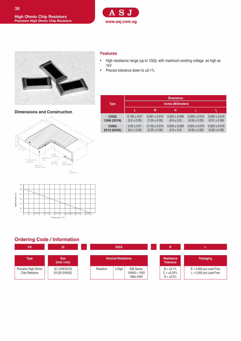
www.asj.com.sg
Features
• High resistance range (up to 1GΩ), with maximum working voltage as high as
1kV
• Precise tolerance down to ±0.1%
Dimensions and Construction
Ordering Code / Information
High Ohmic Chip ResistorsPrecision High Ohmic Chip Resistors
38
Dimensions
Type Inches (Millimeters)
L W H l1 l2
CH321206 (3216)
0.126 ± 0.01
(3.2 ± 0.25)
0.061 ± 0.014
(1.55 ± 0.35)
0.024 ± 0.008
(0.6 ± 0.2)
0.020 ± 0.010
(0.50 ± 0.25)
0.020 ± 0.015
(0.51 ± 0.38)
CH632512 (6432)
0.25 ± 0.01
(6.4 ± 0.25)
0.132 ± 0.014
(3.35 ± 0.35)
0.024 ± 0.008
(0.6 ± 0.2)
0.024 ± 0.010
(0.60 ± 0.25)
0.025 ± 0.015
(0.63 ± 0.38)
CH 32 - XXXX - B L
Type Size(Inch / mm)
Nominal Resistance Resistance Tolerance
Packaging
Precision High Ohmic
Chip Resistors
32 (1206/3216)
63 (2512/6432)
Resistors 4-Digit E96 Series
100KΩ = 1003
1MΩ=1004
B = ±0.1%
C = ±0.25%
D = ±0.5%
E = 4,000 pcs Lead Free
L = 5,000 pcs Lead Free
0
20
135 145115 12575 85 95 105 155
120
35 45 6555
40
60
80
100
25
Temperature (˚C )
Rat
ed P
ower
(%)

Specifications given herein may be changed at any time without prior notice. Please confirm technical specifications with factory before use.
www.asj.com.sgHigh Ohmic Chip Resistors
Precision High Ohmic Chip Resistors
39
Product Type Power Rating @ 25°C
T.C.R (ppm/°C) Max Resistance RangeE-192
B (±0.1%), C (±0.25%), D (±0.5%)
Max Working Voltage Max Overload Voltage
CH321206 (3216)
1/4W
±100 100KΩ to 100MΩ
300V 600V
CH632512 (6432)
1W 1,000V 2,000V
Test Specification Test Method
Resistance Value Within Resistors specification To be measure at 25°C
Resistance Temperature Coefficient Within Specification of TCR 25°C/ +125°C
Pulse Capability 1.0% 2 times of rated voltage, 1.2x 50uS
Resistance to Soldering Heat 0.10% 260°C ± 5°C, 3 seconds
Moisture Resistance 0.50% 40°C ± 2°C, 90% - 95% RH, 1000 hours
Load Life 1.00% 70°C ± 2°C ,1000 hours, 1.5 hours On,0.5 hours Off cycle
Low Temp Exposure 0.50% 24 hrs @ -550 C
High Temp Exposure 0.50% 100 hrs @ 1250 C
Application and Ratings

www.asj.com.sg
Features
• Highlyreliabilityandstability
• Efficient,spaceandcostsaving
• Convexterminations
Dimensions and Construction
Ordering Code / Information
Array & NetworksThick Film Chip Resistor Array
40
20
0160 180120 14040 60 80 100 200
120
-40 -20 200
40
60
80
100
Temperature (˚C )
Rat
ed P
ower
(%)
155˚C
70˚C
-55˚C
(052,102,104.108,162,164)
Dimensions
Type Inches (Millimeters)
L W H L1 L2 P Q
YCN052(0201 X 2)
0.031±0.004
(0.80±0.10)
0.024±0.004
(0.60±0.10)
0.012±0.002
(0.30±0.05)
0.006±0.004
(0.15±0.10)
0.006±0.004
(0.15±0.10)
0.02
(0.50)
0.012±0.004
(0.30±0.10)
YCN102(0402 X 2)
0.040±0.004
(1.00±0.10)
0.040±0.004
(1.00±0.10)
0.012±0.002
(0.30±0.05)
0.006±0.004
(0.15±0.10)
0.010±0.004
(0.25±0.10)
0.03
(0.67)
0.013±0.004
(0.33±0.10)
YCN104(0402 X 4)
0.078±0.004
(2.00±0.10)
0.040±0.004
(1.00±0.10)
0.016±0.004
(0.40±0.10)
0.008±0.004
(0.20±0.10)
0.010±0.004
(0.25±0.10)
0.02
(0.50)
0.012±0.004
(0.30±0.10)
YCN108(0402 X 8)
0.157±0.008
(4.00±0.20)
0.063±0.004
(1.60±0.10)
0.016±0.004
(0.40±0.1)
0.012±0.006
(0.30±0.15)
0.012±0.004
(0.30±0.10)
0.02
(0.50)
0.010±0.004
(0.25±0.10)
YCN162(0603 X 2)
0.063±0.006
(1.60±0.15)
0.063±0.006
(1.60±0.15)
0.018±0.004
(0.45±0.10)
0.012±0.006
(0.30±0.15)
0.012±0.006
(0.30±0.15)
0.031
(0.80)
0.024±0.004
(0.60±0.10)
YCN164(0603 X 4)
0.126±0.008
(3.20±0.20)
0.063±0.006
(1.60±0.15)
0.020±0.004
(0.50±0.10)
0.012±0.006
(0.30±0.15)
0.012±0.006
(0.30±0.15)
0.031
(0.80)
0.020±0.004
(0.50±0.10)
YCN 102 - XXXX - F K
Type Size(Configuration)
Nominal Resistance Resistance Tolerance
Packaging
ThickFilmChipResistor
Array
052-0201X2
102-0402X2
104-0402X4
108-0402X8
162-0603X2
164-0603X4
Resistors
3-Digit
E24Series
2.2Ω=2R2
100Ω=101
D=±0.5%
F=±1%
G=±2%
J=±5%
Z=zeroobm
L=5,000pcsLeadFree
K=10,000pcsLeadFree
4-Digit
E96Series
10.2Ω=10R2
10KΩ=1002
Jumper 000

Specifications given herein may be changed at any time without prior notice. Please confirm technical specifications with factory before use.
www.asj.com.sgArray & Networks
Thick Film Chip Resistor Array
41
Product Type Power Rating@ 70°C
T.C.R (ppm/°C)
Max
ResistanceRange Max Working Voltage
Max Overload Voltage
Operating Temperature
Range
Jumper Rated
Current
Jumper Resistance
ValueE-96
D(±0.5%)E-96
F(±1%)E-24
G(±2%), J(±5%)
YCN052 (0201 X 2)
1/32W
±500 - - 3Ω≤R<10Ω
12.5V 25V
-55°Cto+155°C
0.5A
50mΩmax
±300 - - 10Ω≤R<1KΩ
±200 - - 1KΩ-1MΩ
YCN102 (0402 X 2)
1/16W
±300 - - 1Ω≤R<10Ω
25V 50V
1.0A
±200 - 10Ω≤R≤1MΩ 10Ω≤R≤1MΩ
YCN104 (0402 X 4)
±300 - - 1Ω≤R<10Ω
±200 - 10Ω≤R≤1MΩ 10Ω≤R≤1MΩ
YCN108 (0402 X 8)
±250
-
10Ω-1MΩ 1Ω-1MΩ
-
YCN162 (0603 X 2)
±200
-
10Ω-1MΩ 1Ω-10MΩ
50V 100V-
YCN164 (0603 X 4)
±200 22Ω-470KΩ 1Ω-1MΩ 1Ω-10MΩ
Test Specification Test Method
Resistance Value WithinResistorsspecification Tobemeasureat25°C
Resistance Temperature Coefficient WithinSpecificationofTCR 25°C/+125°C
Short Time Overload±(1.0%+0.05Ω) For1%tolerance
Apply2.5timesofratedvoltageormaximumoverloadvoltagefor
5secswhichislower±(2.0%+0.10Ω) For2%&5%tolerance
Resistance to Soldering Heat ±(1.0%+0.05Ω)
For1%tolerance
260°C±5°C,10seconds±1second
For2%&5%tolerance
Moisture Resistance±(2.0%+0.10Ω) For1%tolerance
40°C±2°C,90%-95%RH,1000hours
±(3.0%+0.10Ω) For2%&5%tolerance
Load Life±(2.0%+0.10Ω) For1%tolerance
70°C±2°C,1000hours,1.5hoursOn,0.5hoursOffcycle
±(3.0%+0.10Ω) For2%&5%tolerance
High Temperature Exposure±(1.0%+0.05Ω) For1%tolerance
155°C,1000hours.Unpowered.Measurementat1000hoursafter
testconclusion.±(2.0%+0.10Ω) For2%&5%tolerance
Application and Ratings

www.asj.com.sg
Features
• Eightbussedresistorelementsincludedinonearray
• Resistornetworktakesupsignificantlylessboardspacethananetworkbasedon
discreteresistors
• Reducesplacementcosts
Dimensions and Construction
Ordering Code / Information
Array & NetworksThick Film Chip Resistor Network
42
20
0160 180120 14040 60 80 100 200
120
-40 -20 200
40
60
80
100
Temperature (˚C )
Rat
ed P
ower
(%)
155˚C
70˚C
-55˚C
YCN 158 - XXX - J L
Type Size(mm) Nominal Resistance Resistance Tolerance
Packaging
ThickFilmChipResistorNetwork 158(0612/1632)
358(1225/3264)
Resistors 3-Digit E24Series
10Ω=100
100Ω=101
J=±5%
E=4,000pcsLeadFree
L=5,000pcsLeadFree
Type
Dimensions
Inches (Millimeters)
L W H L1 L2 P Q
YCN1580612 (1632)
0.126±0.008
(3.20±0.20)
0.063±0.006
(1.60±0.15)
0.018±0.002
(0.45±0.05)
0.012±0.006
(0.30±0.15)
0.014±0.006
(0.35±0.15)
0.025±0.002
(0.64±0.05)
0.018±0.002
(0.45±0.05)
YCN3581225 (3264)
0.252±0.008
(6.40±0.20)
0.126±0.008
(3.20±0.20)
0.043±0.006
(1.10±0.15)
0.020±0.006
(0.50±0.15)
0.020±0.006
(0.50±0.15)
0.050±0.002
(1.27±0.05)
0.035±0.006
(0.90±0.15)
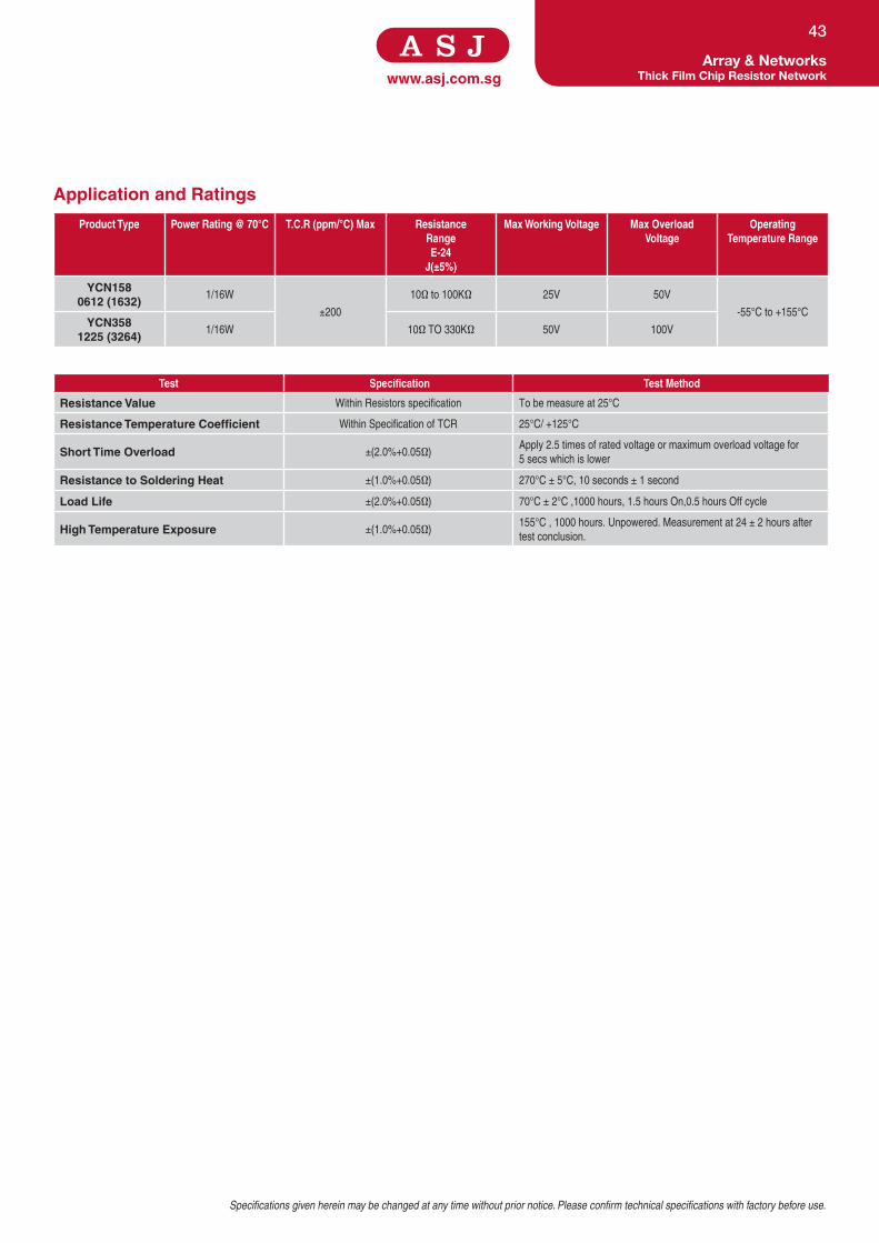
Specifications given herein may be changed at any time without prior notice. Please confirm technical specifications with factory before use.
www.asj.com.sgArray & Networks
Thick Film Chip Resistor Network
43
Product Type Power Rating @ 70°C T.C.R (ppm/°C) Max ResistanceRangeE-24
J(±5%)
Max Working Voltage Max Overload Voltage
Operating Temperature Range
YCN158 0612 (1632)
1/16W
±200
10Ωto100KΩ 25V 50V
-55°Cto+155°C
YCN358 1225 (3264)
1/16W 10ΩTO330KΩ 50V 100V
Test Specification Test Method
Resistance Value WithinResistorsspecification Tobemeasureat25°C
Resistance Temperature Coefficient WithinSpecificationofTCR 25°C/+125°C
Short Time Overload ±(2.0%+0.05Ω)Apply2.5timesofratedvoltageormaximumoverloadvoltagefor
5secswhichislower
Resistance to Soldering Heat ±(1.0%+0.05Ω) 270°C±5°C,10seconds±1second
Load Life ±(2.0%+0.05Ω) 70°C±2°C,1000hours,1.5hoursOn,0.5hoursOffcycle
High Temperature Exposure ±(1.0%+0.05Ω)155°C,1000hours.Unpowered.Measurementat24±2hoursafter
testconclusion.
Application and Ratings

www.asj.com.sg
Features
• TightToleranceandLowT.C.R
• Highlyreliabilityandstability
• Efficicent,spaceandcostsaving
• Convexterminations
Dimensions and Construction
Ordering Code / Information
Array & NetworksThin Film Chip Resistor Array
44
20
0160 180120 14040 60 80 100 200
120
-40 -20 200
40
60
80
100
Temperature (˚C )
Rat
ed P
ower
(%)
125˚C
70˚C
-55˚C
Dimensions
Type Inches (Millimeters)
L W H L1 L2 P Q
LCN164(0603 X 4)
0.126±0.006
(3.20±0.15)
0.063±0.006
(1.60±0.15)
0.020±0.004
(0.50±0.10)
0.019±0.006
(0.30±0.15)
0.019±0.006
(0.30±0.15)
0.031±0.002
(0.80±0.05)
0.020±0.006
(0.50±0.15)
LCN 164 - XXXX - B L - L
Type Size(Configuration)
Nominal Resistance Resistance Tolerance
Packaging T.C.R(ppm/°C)
ThinFilmChip
ResistorArray
164-0603X4 Resistors 4-Digit E24&E96Series
10.2Ω=10R2
10KΩ=1002
B=±0.1%
D=±0.5%
F=±1%
L=5,000pcsLeadFree D=±25
E=±50

Specifications given herein may be changed at any time without prior notice. Please confirm technical specifications with factory before use.
www.asj.com.sgArray & Networks
Thin Film Chip Resistor Array
45
Product Type Power Rating @ 70°C
T.C.R (ppm/°C) Max
Resistance Range Max Working Voltage
Max Overload Voltage
Operating Temperature Range B(±0.1%) D(±0.5%) F(±1%)
LCN164 (0603 X 4)
1/16W
±25
10R≤R≤330KR 75V 150V -55°Cto+125°C
±50
Test Specification Test Method
Resistance Value WithinResistorsspecification Tobemeasureat25°C
Resistance Temperature Coefficient WithinSpecificationofTCR 25°C/+125°C
Short Time Overload ±(0.5%+0.05Ω)Apply2.5timesofratedvoltageormaximumoverloadvoltagefor5secs
whichislower
Moisture Resistance ±(0.5%+0.05Ω)Eachtemperature/humiditycycleisdefinedat8hrs,3cycles/24hrsfor
10days
Load Life ±(0.5%+0.05Ω) 70°C±2°C,1000hours,1.5hoursOn,0.5hoursOffcycle
High Temperature Exposure Meetelectricalandphysicalcharacteristic125°C,1000hours.Unpowered.Measurementat24±2hoursaftertest
conclusion.
Application and Ratings

www.asj.com.sg
Features
• Upto6Configurationsavailablefordifferentapplications(4Pins-12Pins)
• Singleresistorordualresistorsconfigurationavailable
• Tolerancesavailable-1%,2%,5%
Dimensions and Construction
Ordering Code / Information
Array & NetworksThick Film SIP Networks
46
150
120
25 50
40
60
80
100
20
012575 100
Temperature (˚C )
Rat
ed P
ower
(%)
YSN 04 A - 1000 - F A3 - E
Type Number of Pins
Configuration Type Nominal Resistance Resistance Tolerance
Packaging T.C.R (ppm/⁰C)
ThickFilmSIP
Networks
04-4Pins
06-6Pins
07-7Pins
08-8Pins
09-9Pins
10-10Pins
12-12Pins
A-RefertoDiagram
B-RefertoDiagram
C-RefertoDiagram
D-RefertoDiagram
E-RefertoDiagram
F-RefertoDiagram
Resistors 3-Digit
for5%
4-Digitfor
1%
E24Series
2.2Ω=2R2
100Ω=101
F=±1%
G=±2%
J=±5%
A3=Ammo
Pack3Pin
Taping
E=±50
F=±100
(LeaveBlankif
Standard)
Configuration No. A Configuration No. B Configuration No. C
Configuration No. D Configuration No. E Configuration No. F

Specifications given herein may be changed at any time without prior notice. Please confirm technical specifications with factory before use.
www.asj.com.sgArray & Networks
Thick Film SIP Networks
47
Product Type Single Resistor Power Rating Package Power Rating MaxWorkingVoltageConfig. A,C,D,E,F Config. B Config. C 4-Pins 6-Pins 7-Pins 8-Pins 9-Pins 10-Pins 12-Pins
YSN 0.3W 0.5W 0.17W 1W 1.5W 1.75W 2W 2.25W 2.5W 3W 200V
Standard Values - For Configuration A, B, D, E, F
AvailableinE-24series.
ResistanceRange:10Ω-3MΩ(Preferredvaluesinbold)
10,11,12,13,15,16,18,29,22,24,27,30,33,36,39,43,47,51,56,62,68,75, 82,91
Standard Values - For Configuration C, Dual Terminator (R1 / R2)
81Ω/130Ω 160Ω/260Ω 220Ω/270Ω 330Ω/470Ω
120Ω/195Ω 162Ω/260Ω 220Ω/330Ω 330Ω/680Ω
121Ω/195Ω 180Ω/390Ω 330Ω/390Ω 3.0KΩ/6.2KΩ
Test Specification Test Method
Resistance Value WithinResistorsspecification Tobemeasureat25°C
Resistance Temperature Coefficient WithinSpecificationofTCR 25°C/+125°C
Short Time Overload±0.5% For1%tolerance
Apply2.5timesofratedvoltageormaximumoverloadvoltagefor
5secswhichislower±1.0% For2%&5%tolerance
Resistance to Soldering Heat ±0.25% 350°C,5seconds
Moisture Resistance ±(1%+0.1Ω)for1%,2%&5%toleranceresistor 40°C±2°C,90%-95%RH,1000hours
Load Life±(1.0%+0.05Ω) For1%tolerance
70°C±2°C,1000hours,1.5hoursOn,0.5hoursOffcycle
±(2.0%+0.1Ω) For2%&5%tolerance
Application and Ratings

www.asj.com.sg
Features
• Thinfilmprocess
• Highpowerratingupto3Wattsin2512size
• Precisetolerancedownto±0.5%
• ExtremelylowTCRdownto±50PPM/˚C
• Resistancevaluesfrom50mto1ohm
• Highpurityaluminasubstrateforhighpowerdissipation
Dimensions and Construction
Ordering Code / Information
Array & NetworksPrecision Thin Film SIP Networks
48
120
25 50
40
60
80
100
150 175
20
012575 100
Temperature ( C )
Rat
ed P
ower
(%)
Number of PinsDimension ‘L’
Inch (Millimeters)
5 0.550(14.0)
6 0.650(16.5)
7 0.750(19.0)
8 0.850(21.6)
9 0.950(24.1)
10 1.050(26.7)
LSN 05 A - 1000 - F A3 - E
Type Number of Pins
Configuration Type Nominal Resistance Resistance Tolerance
Packaging T.C.R (ppm/°C)
Precision
Thin
FilmSIP
Networks
05-5Pins
06-6Pins
07-7Pins
08-8Pins
09-9Pins
10-10Pins
A-RefertoDiagram
B-RefertoDiagram
C-RefertoDiagram
Resistors 4-Digit
for1%
E192&
E96Series
2.2Ω=2R2
100Ω=101
B=±0.1%
C=±0.25%
D=±0.5%
F=±1%
A3=
Ammo
Pack3Pin
Taping
A=±5
B=±10
C=±15
D=±25
E=±50

Specifications given herein may be changed at any time without prior notice. Please confirm technical specifications with factory before use.
www.asj.com.sgArray & Networks
Precision Thin Film SIP Networks
49
Power Ratings
Configuration Type
Single Resistor
Package Power Max working voltage
Operating Temp
5-Pins 6-Pins 7-Pins 8-Pins 9-Pins 10-Pins
A 0.12W 0.4W 0.5W 0.6W 0.7W 0.8W 0.9W
100V -550to+150
0C
B 0.15W - 0.3W - 0.4W - 0.5W
Resistance Range
Configuration TypeResistance Range
15ppm/°C 25ppm/°C 50ppm/°C
A 1KΩ-10KΩ 100Ω-30KΩ 50Ω-50KΩ
B 1KΩ-30KΩ 100Ω-75KΩ 50Ω-100KΩ
Test Specification Test Method
Resistance Value WithinResistorsspecification Tobemeasureat25°C
Resistance Temperature Coefficient WithinSpecificationofTCR 25°C/+125°C
Short Time Overload ±0.1%Apply2.5timesofratedvoltageormaximumoverloadvoltagefor5secswhich
islower
Resistance to Soldering Heat ±0.1% 260°C±5°C,10seconds±1second
Moisture Resistance ±0.25% 40°C±2°C,90%-95%RH,1000hours
Load Life ±0.25% 70°C±2°C,1000hours,1.5hoursOn,0.5hoursOffcycle
Application and Ratings

www.asj.com.sg
Features
• Excellentanti-sulphurationcharacteristicsduetousageofhighsulphuration-
proofinnertopelectrodematerial
• Excellentheatresistanceandmoistureresistanceensured
• Greaterreliabilityandstabilityinsulphur-richenvironmentscomparedto
standardproducts
• Suitableforbothflowandreflowsoldering
Dimensions and Construction
Ordering Code / Information
SpecialtyAnti-Sulphur Thick Film Chip Resistors
50
20
0160 180120 140 002001080604
120
-40 -20 200
40
60
80
100
Temperature (˚C)
Rat
ed P
ower
(%
)
125˚C 155˚C
70˚C
-55˚C
(16,21,32,40,50,63)
(10)
Dimensions
Type Inches (Millimeters)
L W H l1 l2
SAS100402 (1005)
0.040±0.004
(1.00±0.10)
0.020±0.002
(0.50±0.05)
0.014±0.002
(0.35±0.05)
0.008±0.004
(0.20±0.10)
0.010±0.004
(0.25±0.10)
SAS160603 (1608)
0.063±0.004
(1.60±0.10)
0.031±0.004
(0.80±0.10)
0.018±0.004
(0.45±0.10)
0.012±0.008
(0.30±0.20)
0.012±0.008
(0.30±0.20)
SAS210805 (2012)
0.079±0.006
(2.00±0.15)
0.049±0.004
(1.25±0.10)
0.020±0.004
(0.50±0.10)
0.016±0.008
(0.40±0.20)
0.016±0.008
(0.40±0.20)
SAS321206 (3216)
0.122±0.004
(3.10±0.10)
0.063±0.006
(1.60±0.15)
0.022±0.002
(0.55±0.05)
0.020±0.010
(0.50±0.25)
0.020±0.010
(0.50±0.25)
SAS401210 (3225)
0.122±0.004
(3.10±0.10)
0.098±0.006
(2.50±0.15)
0.022±0.002
(0.55±0.05)
0.020±0.010
(0.50±0.25)
0.016±0.008
(0.40±0.20)
SAS502010 (5025)
0.200±0.006
(5.00±0.15)
0.098±0.006
(2.50±0.15)
0.022±0.002
(0.55±0.05)
0.024±0.010
(0.60±0.25)
0.016±0.008
(0.40±0.20)
SAS632512 (6432)
0.250±0.006
(6.30±0.15)
0.126±0.006
(3.20±0.15)
0.022±0.002
(0.55±0.05)
0.024±0.010
(0.60±0.25)
0.016±0.008
(0.40±0.20)
SAS 10 - XXXX - F K
Type Size(Inch / mm)
Nominal Resistance Resistance Tolerance
Packaging
Anti-Sulphur
ThickFilmChip
Resistors
10(0402/1005)
16(0603/1608)
21(0805/2012)
32(1206/3216)
40(1210/3225)
50(2010/5025)
63(2512/6432)
Resistors
3-Digit
E24Series
2.2Ω=2R2
100Ω=101
D=±0.5%
F=±1%
G=±2%
J=±5%
Z=ZeroOhm
E=4,000pcsLeadFree
L=5,000pcsLeadFree
K=10,000pcsLeadFree
Y=20,000pcsLeadFree
4-Digit
E96Series
10.2Ω=10R2
10KΩ=1002
0.1Ω=R100
Jumper000-5%
0000-1%

Specifications given herein may be changed at any time without prior notice. Please confirm technical specifications with factory before use.
www.asj.com.sgSpecialty
Anti-Sulphur Thick Film Chip Resistors
51
Test Specification Test Method
Resistance Value WithinResistorsspecification Tobemeasureat25°C
Resistance Temperature Coefficient WithinSpecificationofTCR 25°C/+125°C
Short Time Overload±0.5% For1%tolerance
Apply2.5timesofratedvoltageormaximumoverloadvoltagefor
5secswhichislower±1.0% For2%&5%tolerance
Resistance to Soldering Heat±(0.5%+0.05Ω) For1%tolerance
260°C±5°C,10seconds±1second
±(1.0%+0.05Ω) For2%&5%tolerance
Moisture Resistance ±(1%+0.1Ω)for1%,2%&5%toleranceresistor 40°C±2°C,90%-95%RH,1000hours
Load Life±(1.0%+0.05Ω) For1%tolerance
70°C±2°C,1000hours,1.5hoursOn,0.5hoursOffcycle
±(2.0%+0.1Ω) For2%&5%tolerance
High Temperature Exposure±(0.5%+0.05Ω) For1%tolerance
125°C,1000hours.Unpowered.Measurementat24±2hours
aftertestconclusion.±(1.0%+0.05Ω) For2%&5%tolerance
Application and Ratings
Product Type Power Rating @ 70°C
T.C.R (ppm/°C) Max
ResistanceRange
E-96, E-24F(±1%)
ResistanceRangeE-24
G(±2%), J(±5%)
Jumper Rated
Current
Jumper Resistance
Value
Max Working Voltage
Max Overload Voltage
Operating Temperature
Range
SAS10 0402 (1005)
1/16W
±50 10Ω≤R<1MΩ 10Ω≤R<1MΩ
1A
<0.05Ωfor5%
<0.02Ωfor1%
50V 100V
-55°Cto+125°C
±100 10Ω≤R<1MΩ 10Ω≤R<1MΩ
±200
0.1Ω≤R<10Ω 0.1Ω≤R<10Ω
1MΩ≤R≤10MΩ 1MΩ≤R≤10MΩ
SAS16 0603 (1608)
1/10W
±50 10Ω≤R<1MΩ 10Ω≤R<1MΩ
2A
-55°Cto+155°C
±100 10Ω≤R<1MΩ 10Ω≤R<1MΩ
±200
0.1Ω≤R<10Ω 0.1Ω≤R<10Ω
1MΩ≤R≤10MΩ 1MΩ≤R≤10MΩ
SAS21 0805 (2012)
1/8W
±50 10Ω≤R<1MΩ 10Ω≤R<1MΩ
150V 300V
±100 10Ω≤R<1MΩ 10Ω≤R<1MΩ
±200
0.1Ω≤R<10Ω 0.1Ω≤R<10Ω
1MΩ≤R≤10MΩ 1MΩ≤R≤10MΩ
SAS32 1206 (3216)
1/4W
±50 10Ω≤R<1MΩ 10Ω≤R<1MΩ
200V 400V
±100 10Ω≤R<1MΩ 10Ω≤R<1MΩ
±200
0.1Ω≤R<10Ω 0.1Ω≤R<10Ω
1MΩ≤R≤10MΩ 1MΩ≤R≤10MΩ
SAS40 1210 (3225)
1/3W
±50 10Ω≤R<1MΩ 10Ω≤R<1MΩ
±100 10Ω≤R<1MΩ 10Ω≤R<1MΩ
±200
0.1Ω≤R<10Ω 0.1Ω≤R<10Ω
1MΩ≤R≤10MΩ 1MΩ≤R≤10MΩ
SAS50 2010 (5025)
3/4W
±50 10Ω≤R<1MΩ 10Ω≤R<1MΩ
±100 10Ω≤R<1MΩ 10Ω≤R<1MΩ
±200
0.1Ω≤R<10Ω 0.1Ω≤R<10Ω
1MΩ≤R≤10MΩ 1MΩ≤R≤10MΩ
SAS63 2512 (6432)
1W
±50 10Ω≤R<1MΩ 10Ω≤R<1MΩ
3A
±100 10Ω≤R<1MΩ 10Ω≤R<1MΩ
±200
0.1Ω≤R<10Ω 0.1Ω≤R<10Ω
1MΩ≤R≤10MΩ 1MΩ≤R≤10MΩ

www.asj.com.sg
Features
• Suitableforlaserfinetune
• Highlyreliablemultilayerelectrodeconstruction
Dimensions and Construction
Ordering Code / Information
SpecialtyTrimmable Thick Film Chip Resistors
52
20
0160 180120 140 002001080604
120
-40 -20 200
40
60
80
100
Temperature (˚C)
Rat
ed P
ower
(%
)
125˚C 155˚C
70˚C
-55˚C
(16,21,32,40,50,63)
(10)
Type
Dimensions
Inches (Millimeters)
L W H l1 l2
TR100402 (1005)
0.040±0.004
(1.00±0.10)
0.020±0.002
(0.50±0.05)
0.014±0.002
(0.35±0.05)
0.008±0.004
(0.20±0.10)
0.010±0.004
(0.25±0.10)
TR160603 (1608)
0.063±0.004
(1.60±0.10)
0.031±0.004
(0.80±0.10)
0.018±0.004
(0.45±0.10)
0.012±0.008
(0.30±0.20)
0.012±0.008
(0.30±0.20)
TR210805 (2012)
0.079±0.006
(2.00±0.15)
0.049±0.004
(1.25±0.10)
0.020±0.004
(0.50±0.10)
0.016±0.008
(0.40±0.20)
0.016±0.008
(0.40±0.20)
TR321206 (3216)
0.122±0.004
(3.10±0.10)
0.063±0.006
(1.60±0.15)
0.022±0.002
(0.55±0.05)
0.020±0.010
(0.50±0.25)
0.020±0.010
(0.50±0.25)
TR401210 (3225)
0.122±0.004
(3.10±0.10)
0.098±0.006
(2.50±0.15)
0.022±0.002
(0.55±0.05)
0.020±0.010
(0.50±0.25)
0.016±0.008
(0.40±0.20)
TR502010 (5025)
0.200±0.006
(5.00±0.15)
0.098±0.006
(2.50±0.15)
0.022±0.002
(0.55±0.05)
0.024±0.010
(0.60±0.25)
0.016±0.008
(0.40±0.20)
TR632512 (6432)
0.250±0.006
(6.30±0.15)
0.126±0.006
(3.20±0.15)
0.022±0.002
(0.55±0.05)
0.024±0.010
(0.60±0.25)
0.016±0.008
(0.40±0.20)
TR 10 - XXX - N K
Type Size(Inch / mm)
Nominal Resistance Resistance Tolerance
Packaging
TrimmableThickFilm
ChipResistors
10(0402/1005)
16(0603/1608)
21(0805/2012)
32(1206/3216)
40(1210/3225)
50(2010/5025)
63(2512/6432)
Resistors 3-Digit E24Series
2.2Ω=2R2
100Ω=101
N=0~-30%
M=0~-15%
K=±10%
L=±15%
E=4,000pcsLeadFree
L=5,000pcsLeadFree
K=10,000pcsLeadFree

Specifications given herein may be changed at any time without prior notice. Please confirm technical specifications with factory before use.
www.asj.com.sgSpecialty
Trimmable Thick Film Chip Resistors
53
Product Type Power Rating @ 70°C
T.C.R (ppm/°C) Max
ResistanceRangeE-24
N(0~-30%), M(0~-15%)K(±10%), L(±15%)
Max Working Voltage
Max Overload Voltage
Operating Temperature Range
TR100402 (1005)
1/16W
±100 10Ω≤R<1MΩ
50V 100V
-55°Cto+125°C
±200 1MΩ≤R<10MΩ
TR160603 (1608)
1/10W
±100 10Ω≤R<1MΩ
-55°Cto+155°C
±200 1MΩ≤R<10MΩ
TR210805 (2012)
1/8W
±100 10Ω≤R<1MΩ
150V 300V
±200 1MΩ≤R<10MΩ
TR321206 (3216)
1/4W
±100 10Ω≤R<1MΩ
200V 400V
±200 1MΩ≤R<10MΩ
TR401210 (3225)
1/3W
±100 10Ω≤R<1MΩ
±200 1MΩ≤R<10MΩ
TR502010 (5025)
3/4W
±100 10Ω≤R<1MΩ
±200 1MΩ≤R<10MΩ
TR632512 (6432)
1W
±100 10Ω≤R<1MΩ
±200 1MΩ≤R<10MΩ
Test Specification Test Method
Resistance Value WithinResistorsspecification Tobemeasureat25°C
Resistance Temperature Coefficient WithinSpecificationofTCR 25°C/+125°C
Short Time Overload±0.5% For1%tolerance
Apply2.5timesofratedvoltageormaximumoverloadvoltagefor
5secswhichislower±1.0% For2%&5%tolerance
Resistance to Soldering Heat±(0.5%+0.05Ω) For1%tolerance
260°C±5°C,10seconds±1second
±(1.0%+0.05Ω) For2%&5%tolerance
Moisture Resistance ±(1%+0.1Ω)for1%,2%&5%toleranceresistor 40°C±2°C,90%-95%RH,1000hours
Load Life±(1.0%+0.05Ω) For1%tolerance
70°C±2°C,1000hours,1.5hoursOn,0.5hoursOffcycle
±(2.0%+0.1Ω) For2%&5%tolerance
High Temperature Exposure±(0.5%+0.05Ω) For1%tolerance
125°C,1000hours.Unpowered.Measurementat24±2hours
aftertestconclusion.±(1.0%+0.05Ω) For2%&5%tolerance
Application and Ratings

www.asj.com.sg
Features
• Largeterminalsandoptimizedbodyshapeforpowerdissipation
• Extremelyprecisetolerance(±0.01%),LowTemperatureCoefficientof
Resistanceof±30ppm
• Widelyusedinapplicationswheresurgevoltagesorinsurgecurrentsarepresent
Dimensions and Construction
Ordering Code / Information
SpecialtySMD WireWound Resistors (Chip Type)
54
Standard Models
Dimensions
Type Inches (Millimeters)
A B (Max) C D (Min) E F G HSWC1/2 (1/2W)
0.204±0.02
(5.2±0.5)
0.111
(2.82)
0.125±0.01
(3.2±0.25)
0.025
(0.63)
0.045±0.015
(1.14±0.4)
0.08
(2.0)
0.1
(2.5)
0.08
(2.0)
SWC1 (1W)
0.258±0.02
(6.55±0.5)
0.125
(3.17)
0.15±0.015
(3.8±0.4)
0.032
(0.8)
0.06±0.015
(1.15±0.4)
0.1
(2.5)
0.125
(3.2)
0.12
(3.0)
SWC2 (2W)
0.449±0.032
(11.4±0.8)
0.208
(5.28)
0.225±0.015
(5.7±0.4)
0.06
(1.5)
0.07±0.02
(1.78±0.5)
0.16
(4.0)
0.157
(4.0)
0.2
(5.0)
SWC2SS (2W)
0.297±0.02
(7.5±0.5)
0.165
(4.19)
0.15±0.015
(3.8±0.4)
0.044
(1.1)
0.05±0.016
(1.27±0.4)
0.1
(2.5)
0.125
(3.2)
0.14
(3.6)
SWC27 (2.7W)
0.48±0.032
(12.2±0.8)
0.23
(5.84)
0.228±0.016
(5.8±0.4)
0.05
(1.27)
0.07±0.02
(1.78±0.5)
0.16
(4.0)
0.18
(4.57)
0.2
(5.0)
SWC3 (3W)
0.625±0.032
(15.9±0.8)
0.27
(6.86)
0.275±0.015
(7±0.38)
0.05
(1.27)
0.085±0.016
(2.16±0.4)
0.16
(4.0)
0.175
(4.5)
0.4
(10.0)
SWC35 (3.5W)
0.811±0.020
(20.6±0.5)
0.295
(7.49)
0.273±0.02
(6.9±0.5)
0.063
(1.6)
0.102±0.028
(2.6±0.7)
0.2
(5.0)
0.2
(5.0)
0.6
(15.0)
SWC5 (5W)
0.811±0.02
(20.6±0.5)
0.295
(7.49)
0.273±0.02
(6.9±0.5)
0.063
(1.6)
0.102±0.028
(2.6±0.7)
0.2
(5.0)
0.25
(6.4)
0.6
(15.0)
Low Profile Metal Plate Models
Dimensions
Type Inches (Millimeters)
A B (Max) C D (Min) E (Minimum) F G H
SWC1/2L (1/2W)
0.2±0.012
(5.1±0.3)
0.053
(1.35)
0.1±0.01
(2.54±0.25)
0.025
(0.63)
0.06
(1.5)
0.08
(2.0)
0.1
(2.5)
0.08
(2.0)
SWC1L (1W)
0.25±0.012
(6.3±0.3)
0.057
(1.45)
0.126±0.012
(3.2±0.3)
0.025
(0.63)
0.07
(1.8)
0.15
(3.8)
0.125
(3.2)
0.12
(3.0)
SWC2L (2W)
0.33±0.012
(8.38±0.3)
0.057
(1.45)
0.157±0.012
(4.0±0.3)
0.032
(0.8)
0.1
(2.5)
0.197
(5.0)
0.157
(4.0)
0.157
(4.0)
SWC2SSL (2W)
0.25±0.012
(6.3±0.3)
0.079
(2.0)
0.126±0.012
(3.2±0.3)
0.032
(0.8)
0.08
(0.2)
0.15
(3.8)
0.125
(3.2)
0.12
(0.3)
SWC 1/2 L - XXXX - F TR - F
Type Power Rating
Option Nominal Resistance Resistance Tolerance
Packaging T.C.R(ppm/°C)
SMD
WireWound
Resistors
(ChipType)
1/2-1/2W
1-1W
2-2W
2SS-2W
27-2.7W
3-3W
35-3.5W
5-5W
X=NonInductive
P=IncreasedPulseCapability
M=PowerMetalFilmElement
L=LowProfileNon-Inductive
MetalPlateDesign
E=LowThermalEMFDesign
(Leaveblankifstandard)
(RefertoApplicationNotes)
Resistors
3-Digit
E24Series
2.2Ω=2R2
100Ω=101
T=±0.01%
Q=±0.02%
A=±0.05%
B=±0.1%
C=±0.25%
D=±0.5%
F=±1%
G=±2%
J=±5%
TR A=±5
B=±10
20=±20
D=±25
30=±30
E=±50
F=±100
G=±200
(LeaveBlankif
Standard)
4-Digit
E96,E192
Series
10.2Ω=10R2
10KΩ=1002
5-Digit
Resistance
values
below0.001Ω
0.0005Ω=R0005
Derating Information
1. StandardSWC1/2toSWC5arederatedby0.67%/°Cwhen
ambienttemperatureexceeds25°C.
2. LowProfilepartsSWC1/2LtoSWC2SSLarederatedby
0.95%/°Cabove70°C.

Specifications given herein may be changed at any time without prior notice. Please confirm technical specifications with factory before use.
www.asj.com.sgSpecialty
SMD WireWound Resistors (Chip Type)
55
Product Type Power Rating
WireWound & Option L Metal Plate Option M Film Element Operating Temperature
RangeT.C.R (ppm/°C) Max
(Standard parts power rated @ 25°C, Low Profile parts
power rated @ 70°C)
Resistance Range E-192, E-96, E-24
T(±0.01%), Q(±0.02%), A(±0.05%), B(±0.1%), C(±0.25%), D(±0.5%),
F(±1%), G(±2%), J(±5%)
Max Working Voltage
T.C.R (ppm/°C) Max Resistance Range E-192, E-96, E-24
C(± 0.25%), D(± 0.5%),
F(± 1%), G(± 2%), J(± 5%)
Max Working Voltage
SWC1/2 1/2W
0.0005Ω≤X<0.025Ω
(±400)
0.025Ω≤X<0.05Ω(±300)
0.05Ω≤X<0.1Ω(±200)
0.1Ω≤X<1Ω(±90)
1Ω≤X<10Ω(±50)
>10Ω(±30)
0.01Ω-2KΩ 33V
0.1Ω≤X<1Ω(±350)
1Ω≤X<10Ω(±200)
>10Ω(±100)
5Ω-1MΩ 33V
-55°Cto
+175°C
SWC1 1W 0.001Ω-10KΩ 58V 0.1Ω-1MΩ 58V
SWC2 2W 0.002Ω-25KΩ 120V 0.1Ω-1MΩ 120V
SWC2SS 2W 0.1Ω-200Ω 80V 1Ω-1MΩ 80V
SWC27 2.7W 0.005Ω-20KΩ 180V 1Ω-1MΩ 180V
SWC3 3W 0.005Ω-25KΩ 200V 1Ω-1MΩ 200V
SWC35 3.5W 0.005Ω-50KΩ 250V 1Ω-1MΩ 250V
SWC5 5W 0.005Ω-100kΩ 300V - 300V
SWC1/2L 1/2W 0.003Ω-0.05Ω √(P*R) - -
SWC1L 1W 0.001Ω-0.1Ω √(P*R) - -
SWC2L 2W 0.002Ω-0.2Ω √(P*R) - -
SWC2SSL 2W 0.0005Ω-0.005Ω √(P*R) - -
Temperature Coefficient of Resistance
Standard WireWound Type / Option L (Low Profile Non-Inductive Metal Plate Design)
Option M (Power Metal Film Element)
Resistance Value Standard (ppm/°C) Optional (ppm/°C) Standard (ppm/°C) Optional (ppm/°C)
0.0005Ω-0.024Ω 400 100,200 - -
0.025Ω-0.049Ω 300 100,200 - -
0.050Ω-0.099Ω 200 50,100 - -
0.1Ω-0.99Ω 90 20,30,50 350 200
1Ω-9.9Ω 50 10,20,30 200 100
10Ω&above 30 5,10,20 100 25,50
Application Notes:
1. Power Rating:Resistorsmaybeoperateduptofullratedpowerwithconsiderationofmountingdensity,padandtracegeometery,PCBmaterial,andambienttemperature.Standardpartsshouldbederated(Power&Voltage)by0.67%/°Cwhenambienttemperatureexceeds25°C.LowProfilemodelsshouldbederatedby1%/°Cabove70°C.
2. Inductance:Standardwirewoundparts’inductancearetypically1uHto20uH.ForOptionX(NonInductivedesign),theinductanceforresistance≤50Ωis0.2uHmaximum,
and0.37uHforresistance>50Ω.OptionL(LowProfileNon-InductiveMetalPlateDesign)andOptionM(PowerMetalFilmElement)areinherentlylowinductance(Typically
1nHto10nH).Consultfactoryformoreinformation.
3. Pulse Capability:StandardSWCseries(WireWound)andOptionL(LowProfileNon-InductiveMetalPlateDesign)offerexcellentoverloadcapability,greatlyexceedingthatof
filmresistors.Theoverloadlevelcanoftenbeeconomicallyenhancedbyafactorof50%ormoreviaselectingOptionP(IncreasedPulseCapability).Pulsecapabilityishighly
dependentonsizeandresistance(availableupto50Joules).Consultfactoryformoreinformation.
Application and Ratings

www.asj.com.sgPackaging / Taping Specifications (SMD)Chip Resistors
56
Tape Dimensions
Chip Resistors
Inches (Millimeters)
Dimensions A B W E F
Chip Resistor 050201 (0603)
0.015 ± 0.002
(0.38 ± 0.05)
0.027 ± 0.002
(0.68 ± 0.05)
0.315 ± 0.008
(8.00 ± 0.20)
0.069 ± 0.004
(1.75 ± 0.10)
0.138 ± 0.002
(3.50 ± 0.05)
Chip Resistor 100402 (1005)
0.045 ± 0.004
(1.15 ± 0.10)
0.026 ± 0.004
(0.65 ± 0.10)
0.315 ± 0.008
(8.00 ± 0.20)
0.069 ± 0.004
(1.75 ± 0.10)
0.138 ± 0.002
(3.50 ± 0.05)
Chip Resistor 160603 (1608)
0.075 ± 0.004
(1.90 ± 0.10)
0.043 ± 0.004
(1.10 ± 0.10)
0.315 ± 0.008
(8.00 ± 0.20)
0.069 ± 0.004
(1.75 ± 0.10)
0.138 ± 0.002
(3.50 ± 0.05)
Chip Resistor 210805 (2012)
0.094 ± 0.004
(2.40 ± 0.10)
0.065 ± 0.004
(1.65 ± 0.10)
0.315 ± 0.008
(8.00 ± 0.20)
0.069 ± 0.004
(1.75 ± 0.10)
0.138 ± 0.002
(3.50 ± 0.05)
Chip Resistor 321206 (3216)
0.138 ± 0.004
(3.50 ± 0.10)
0.075 ± 0.004
(1.90 ± 0.10)
0.315 ± 0.008
(8.00 ± 0.20)
0.069 ± 0.004
(1.75 ± 0.10)
0.138 ± 0.002
(3.50 ± 0.05)
Chip Resistor 401210 (3225)
0.138 ± 0.004
(3.50 ± 0.10)
0.110 ± 0.004
(2.80 ± 0.10)
0.315 ± 0.008
(8.00 ± 0.20)
0.069 ± 0.004
(1.75 ± 0.10)
0.138 ± 0.002
(3.50 ± 0.05)
Chip Resistor 502010 (5025)
0.213 ± 0.008
(5.40 ± 0.20)
0.114 ± 0.008
(2.90 ± 0.20)
0.472 ± 0.004
(12.0 ± 0.10)
0.069 ± 0.004
(1.75 ± 0.10)
0.217 ± 0.002
(5.50 ± 0.05)
Chip Resistor 632512 (6432)
0.272 ± 0.008
(6.60 ± 0.20)
0.142 ± 0.008
(3.60 ± 0.20)
0.472 ± 0.004
(12.0 ± 0.10)
0.069 ± 0.004
(1.75 ± 0.10)
0.217 ± 0.002
(5.50 ± 0.05)
Inches (Millimeters)
Dimensions T1 T2 P D
Chip Resistor 050201 (0402) -
0.012 ± 0.004
(0.31 ± 0.10)
0.079 ± 0.002
(2.00 ± 0.05)
0.059
± 0.004
– 0
(1.5
+ 0.10
– 0 )
Chip Resistor 100402 (1005) -
0.018 ± 0.004
(0.45 ± 0.10)
0.079 ± 0.002
(2.00 ± 0.05)
0.059
± 0.004
– 0
(1.5
+ 0.10
– 0 )
Chip Resistor 160603 (1608) -
0.024 ± 0.004
(0.60 ± 0.10)
0.157 ± 0.004
(4.00 ± 0.10)
0.059
± 0.004
– 0
(1.5
+ 0.10
– 0 )
Chip Resistor 210805 (2012) -
0.030 ± 0.004
(0.75 ± 0.10)
0.157 ± 0.004
(4.00 ± 0.10)
0.059
± 0.004
– 0
(1.5
+ 0.10
– 0 )
Chip Resistor 321206 (3216) -
0.030 ± 0.004
(0.75 ± 0.10)
0.157 ± 0.004
(4.00 ± 0.10)
0.059
± 0.004
– 0
(1.5
+ 0.10
– 0 )
Chip Resistor 401210 (3225) -
0.030 ± 0.004
(0.75 ± 0.10)
0.157 ± 0.004
(4.00 ± 0.10)
0.059
± 0.004
– 0
(1.5
+ 0.10
– 0 )
Chip Resistor 502010 (5025)
0.008 ± 0.004
(0.20 ± 0.10)-
0.157 ± 0.004
(4.00 ± 0.10)
0.059
± 0.004
– 0
(1.5
+ 0.10
– 0 )
Chip Resistor 632512 (6432)
0.008 ± 0.004
(0.20 ± 0.10)-
0.315 ± 0.004
(4.00 ± 0.10)
0.059
± 0.004
– 0
(1.5
+ 0.10
– 0 )

Specifications given herein may be changed at any time without prior notice. Please confirm technical specifications with factory before use.
www.asj.com.sgPackaging / Taping Specifications (SMD)
Arrays & Networks
57
Array & Networks
Inches (Millimeters)
Dimensions A B W E F P1
YCN0520201 X 2
0.028 ± 0.004
(0.7 ± 0.1)
0.035 ± 0.004
(0.9 ± 0.1)
0.315 ± 0.008
(8.0 ± 0.2)
0.069 ± 0.004
(1.75 ± 0.1)
0.138 ± 0.002
(3.5 ± 0.05)
0.079 ± 0.004
(2.0 ± 0.1)
YCN1020402 X 2
0.047 ± 0.004
(1.2 ± 0.1)
0.047 ± 0.004
(1.2 ± 0.1)
0.315 ± 0.008
(8.0 ± 0.2)
0.069 ± 0.004
(1.75 ± 0.1)
0.138 ± 0.002
(3.5 ± 0.05)
0.079 ± 0.004
(2.0 ± 0.1)
YCN1040402 X 4
0.047 ± 0.004
(1.2 ± 0.1)
0.087 ± 0.004
(2.2 ± 0.1)
0.315 ± 0.008
(8.0 ± 0.2)
0.069 ± 0.004
(1.75 ± 0.1)
0.138 ± 0.002
(3.5 ± 0.05)
0.079 ± 0.004
(2.0 ± 0.1)
YCN1080402 X 8
0.075 ± 0.008
(1.9 ± 0.2)
0.169 ± 0.008
(4.3 ± 0.2)
0.472 ± 0.008
(12.0 ± 0.2)
0.069 ± 0.004
(1.75 ± 0.1)
0.138 ± 0.002
(3.5 ± 0.05)
0.157 ± 0.004
(4.0 ± 0.1)
YCN1620603 X 2
0.075 ± 0.004
(1.9 ± 0.1)
0.075 ± 0.004
(1.9 ± 0.1)
0.315 ± 0.008
(8.0 ± 0.2)
0.069 ± 0.004
(1.75 ± 0.1)
0.138 ± 0.002
(3.5 ± 0.05)
0.157 ± 0.004
(4.0 ± 0.1)
YCN1640603 X 4
0.075 ± 0.004
(1.9 ± 0.1)
0.136 ± 0.004
(3.45 ± 0.1)
0.315 ± 0.008
(8.0 ± 0.2)
0.069 ± 0.004
(1.75 ± 0.1)
0.138 ± 0.002
(3.5 ± 0.05)
0.157 ± 0.004
(4.0 ± 0.1)
YCN1580612 (1632)
0.079 ± 0.004
(2.0 ± 0.1)
0.138 ± 0.004
(3.5 ± 0.1)
0.315 ± 0.008
(8.0 ± 0.2)
0.069 ± 0.004
(1.75 ± 0.1)
0.138 ± 0.002
(3.5 ± 0.05)
0.157 ± 0.002
(4.0 ± 0.05)
YCN3581225 (3264)
0.138 ± 0.008
(3.5 ± 0.2)
0.264 ± 0.008
(6.7 ± 0.2)
0.472 ± 0.008
(12.0 ± 0.2)
0.069 ± 0.004
(1.75 ± 0.1)
0.138 ± 0.002
(3.5 ± 0.05)
0.157 ± 0.004
(4.0 ± 0.1)
LCN1640603 X 4
0.079 ± 0.004
(2.0 ± 0.1)
0.138 ± 0.004
(3.5 ± 0.1)
0.315 ± 0.008
(8.0 ± 0.2)
0.069 ± 0.004
(1.75 ± 0.1)
0.138 ± 0.002
(3.5 ± 0.05)
0.157 ± 0.002
(4.0 ± 0.05)
Inches (Millimeters)
Dimensions P2 P0 D0 T2 T
YCN0520201 X 2
0.079 ± 0.002
(2.0 ± 0.05)
0.157 ± 0.002
(4.0 ± 0.05)
0.059
± 0.004
– 0
(1.5
+ 0.10
– 1)
0.018
± 0.008
– 0
(0.45
+ 0.2
– 0)
0.017 ± 0.004
(0.43 ± 0.1)
YCN1020402 X 2
0.079 ± 0.002
(2.0 ± 0.05)
0.157 ± 0.002
(4.0 ± 0.05)
0.059
± 0.004
– 0
(1.5
+ 0.10
– 1)
0.018
± 0.008
– 0
(0.45
+ 0.2
– 0)
0.017 ± 0.004
(0.43 ± 0.1)
YCN1040402 X 4
0.079 ± 0.002
(2.0 ± 0.05)
0.157 ± 0.002
(4.0 ± 0.05)
0.059
± 0.004
– 0
(1.5 + 0.10
– 1)
0.025
± 0.008
– 0
(0.60
+ 0.2
– 0)
0.024 ± 0.004
(0.6 ± 0.1)
YCN1080402 X 8
0.079 ± 0.002
(2.0 ± 0.05)
0.157 ± 0.002
(4.0 ± 0.05)
0.059
± 0.004
– 0
(1.5
+ 0.10
– 1)
0.025
± 0.008
– 0
(0.60
+ 0.2
– 0)
0.024 ± 0.004
(0.6 ± 0.1)
YCN1620603 X 2
0.079 ± 0.002
(2.0 ± 0.05)
0.157 ± 0.002
(4.0 ± 0.05)
0.059
± 0.004
– 0
(1.5
+ 0.10
– 1)
0.025
± 0.008
– 0
(0.60
+ 0.2
– 0)
0.024 ± 0.004
(0.6 ± 0.1)
YCN1640603 X 4
0.079 ± 0.002
(2.0 ± 0.05)
0.157 ± 0.002
(4.0 ± 0.05)
0.059
± 0.004
– 0
(1.5
+ 0.10
– 1)
0.03
± 0.008
– 0
(0.75
+ 0.2
– 0)
0.030 ± 0.004
(0.75 ± 0.1)
YCN1580612 (1632)
0.079 ± 0.002
(2.0 ± 0.05)
0.157 ± 0.004
(4.0 ± 0.1)
0.059
± 0.004
– 0
(1.5
+ 0.10
– 1)
0.033
± 0.004
– 0
(0.85
+ 0.10
– 0)
-
YCN3581225 (3264)
0.079 ± 0.002
(2.0 ± 0.05)
0.157 ± 0.004
(4.0 ± 0.1)
0.059
± 0.004
– 0
(1.5 + 0.10
– 1)
- -
LCN1640603 X 4
0.079 ± 0.002
(2.0 ± 0.05)
0.157 ± 0.004
(4.0 ± 0.1)
0.059 ± 0.004
– 0
(1.5
+ 0.10
– 0)
0.033
± 0.004
– 0
(0.85
+ 0.10
– 0)
-
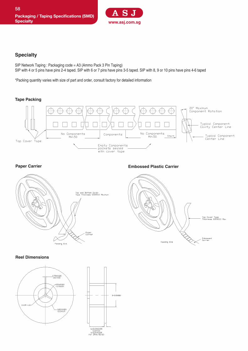
www.asj.com.sgPackaging / Taping Specifications (SMD)Specialty
58
Specialty
SIP Network Taping : Packaging code = A3 (Ammo Pack 3 Pin Taping)
SIP with 4 or 5 pins have pins 2-4 taped. SIP with 6 or 7 pins have pins 3-5 taped. SIP with 8, 9 or 10 pins have pins 4-6 taped
*Packing quantity varies with size of part and order, consult factory for detailed information
Tape Packing
Paper Carrier Embossed Plastic Carrier
Reel Dimensions

Specifications given herein may be changed at any time without prior notice. Please confirm technical specifications with factory before use.
www.asj.com.sgPackaging / Taping Specifications (SMD)
Packing Quantity
59
Packing Quantity
Thick Film Chip Resistors
Reels (Diameter A)
Component / Reel
Paper Carrier Embossed Plastic Carrier
Chip Resistor 03,05 Chip Resistor 10 Chip Resistor 16/21/32/40 CLS 32/50/63 Chip Resistor 50/63
7” (178 ± 2.0mm) 20,000 10,000
5,000 2,000 4,000
5,000 -
10” (254 ± 2.0mm) - - 10,000 - -
13” (330 ± 2.0mm) - 50,000 20,000 - 10,000
Packing Quantity
Array & Networks
Reels (Diameter A)
Component / Reel
Paper Carrier
YCN052 / YCN102 / YCN104 (2mm Pitch) YCN108 / YCN162 / YCN164 (4mm Pitch)
7” (178 ± 2.0mm) 10,000 5,000
10” (254 ± 2.0mm) 20,000 10,000
13” (330 ± 2.0mm) 30,000 15,000
*Tape width for YCN052 / YCN102 / YCN104 / YCN162 / YCN164 is 8mm, and tape width for YCN 108 is 12mm
Packing QuantitySpecialty
Series Power Rating
Tape & Reel Type / Dimensions
Packing Qty (pcs)
Tape Type Tape Width Reel size
SWC1/2 1/2W Embossed Plastic 12mm 13” 2,500 / 5,000
SWC1 1W Embossed Plastic 12mm 13” 2,500
SWC2 2W Embossed Plastic 24mm 13” 1,000
SWC2SS 2W Embossed Plastic 16mm 13” 2,000
SWC27 2.7W Embossed Plastic 24mm 13” 1,000
SWC3 3W Embossed Plastic 32mm 13” 800
SWC35 3.5W Embossed Plastic 44mm 13” 750
SWC5 5W Embossed Plastic 44mm 13” 750
SWC1/2L 1/2W Embossed Plastic 12mm 13” 2,500 / 5,000
SWC1L 1W Embossed Plastic 12mm 13” 3,000
SWC2L 2W Embossed Plastic 24mm 13” 2,000
SWC2SSL 2W Embossed Plastic 12mm 13” 2,000
*Above information serves as a standard Tape & Reel selection guide for user. Specifications to change without notice.
Consult factory for detailed information before ordering

www.asj.com.sgSoldering Pad Dimensions
60
Soldering Pad Dimensions for Chip Resistors Product (Type)
Land Dimensions - Inches (mm)
A B C
Chip Resistor 05 (0201)
0.012 ( 0.3 ) 0.04 ( 1.0 ) 0.016 ( 0.4 )
Chip Resistor 10 (0402)
0.20 (0.5 ) 0.059 ( 1.5 ) 0.020~0.024 (0.5~0.6)
Chip Resistor 16 (0603)
0.039 (1.0 ) 0.106 (2.7 ) 0.020~0.035 (0.5~0.9)
Chip Resistor 21 (0805)
0.047 (1.2 ) 0.138 (3.5 ) 0.043~0.051 (1.1~1.3 )
Chip Resistor 32 (1206)
0.087 ( 2.2 ) 0.197 ( 5.0 ) 0.055~0.071 (1.4~1.8 )
Chip Resistor 40 (1210)
0.087 ( 2.2 ) 0.197 ( 5.0 ) 0.083~0.118 (2.1~3.0)
Chip Resistor 50 (2010)
0.15 ( 3.9 ) 0.331 ( 8.4 ) 0.083~0.118 (2.1~3.0)
Chip Resistor 63 (2512)
0.205 ( 5.2 ) 0.413 ( 10.5 ) 0.098~0.189 (2.5~4.8)
Soldering Pad Dimensions for Chip Array & Networks
Product (Type)
Land Dimensions - Inches (mm)
A B P Q1 Q2
YCN052 0.012 (0.3) 0.035 (0.9) 0.02 (0.5) 0.012 (0.3) 0.012 (0.3)
YCN102 0.02 (0.5) 0.079 (2.0) 0.026 (0.67) 0.013 (0.33) 0.013 (0.34)
YCN162 0.039 (1.0) 0.102 (2.6) 0.031 (0.8) 0.016 (0.4) 0.016 (0.4)
YCN104 0.02 (0.5) 0.079 (2.0) 0.02 (0.5) 0.011 (0.28) 0.009 (0.22)
YCN164 0.039 (1.0) 0.102 (2.6) 0.031 (0.8) 0.016 (0.4) 0.016 (0.4)
YCN108 0.039 (1.0) 0.079 (2.0) 0.02 (0.5) 0.010 (0.25) 0.010 (0.25)
Soldering Pad Dimensions for SMD Wirewound
Product (Type)Land Dimensions - Inches (mm)
A B C
SWC1/2 0.08 (2.0) 0.10 (2.5) 0.08 (2.0)
SWC1 0.12 (3.0) 0.125 (3.2) 0.10 (2.5)
SWC2 0.20 (5.0) 0.157 ( 4.0) 0.16 (4.0)
SWC2SS 0.14 (3.6) 0.125 (3.2) 0.10 (2.5)
SWC27 0.20 (5.0) 0.18 (4.57) 0.16 (4.0)
SWC3 0.40 (10.0) 0.175 (4.5) 0.16 (4.0)
SWC35 0.60 (15.0) 0.20 (5.0) 0.20 (5.0)
SWC5 0.60 (15.0) 0.25 (6.4) 0.25 (6.4)
SWC1/2L 0.08 (2.0) 0.10 (2.5) 0.08 (2.0)
SWC1L 0.12 (3.0) 0.125 (3.2) 0.15 (3.8)
SWC2L 0.157 (4.0) 0.157 (4.0) 0.197 (5.0)
SWC2SSL 0.12 (3.0) 0.125 (3.2) 0.15 (3.8)
Q1 Q2
BA
P
BA
Q2Q1
P
P
Q1 Q2
A B
B
A

Specifications given herein may be changed at any time without prior notice. Please confirm technical specifications with factory before use.
www.asj.com.sgMarking Information
Resistance Value Code
61
NUMERIC NUMBERING (CHIP RESISTOR)
5% Tolerance: 3 digits (First 2 digits are significant figures, third digit is number of zeros. Letter R is decimal point).
* 4 digits alpha numeric marking for ultra low resistance chip resistor.
1R0 1.0 ohm
100 10 ohm
101 100 ohm
1% Tolerance: 4 digits (First 3 digits are significant figures, fourth digit is number zeros. Letter R is decimal point).
Examples
1R00 1.0 ohm
10R0 10.0 ohm
1000 100 ohm
1001 1K ohm
0603 1% E-96 MARKING
Code R Value Code R Value Code R Value Code R Value Code R Value
01 100 21 162 40 255 59 402 78 634
02 102 22 165 41 261 60 412 79 649
03 105 23 169 42 267 61 422 80 665
04 107 24 174 43 274 62 432 81 681
05 110 25 178 44 280 63 442 82 698
06 113 26 182 45 287 64 453 83 715
07 115 27 187 46 294 65 464 84 732
08 118 28 191 47 301 66 475 85 750
09 121 29 196 48 309 67 487 86 768
10 124 30 200 49 316 68 499 87 787
11 127 31 205 50 324 69 511 88 806
12 130 32 210 51 332 70 523 89 825
13 133 33 215 52 340 71 536 90 845
14 137 34 221 53 348 72 549 91 866
15 140 35 226 54 357 73 562 92 887
16 143 36 232 55 365 74 576 93 909
17 147 37 237 56 374 75 590 94 931
18 150 38 243 57 383 76 604 95 953
19 154 39 249 58 392 77 619 96 976
20 158
This table shows the first two digits for the three-digits E-96 part marking scheme. The third character is a letter multiplier:
Y=10-2
X=10-1
A=100
B=101
C=102
D=103
E=104
F=105
Example:
1K = 01B (100x101 = 1000)
10K = 01C (100x102 = 10000)
100K = 01D
Marking for 0603 1% will be as per table above except for those resistance values available in E24 series and not in E96 series will be in three-
digits (e.g. 12Ω = 120)
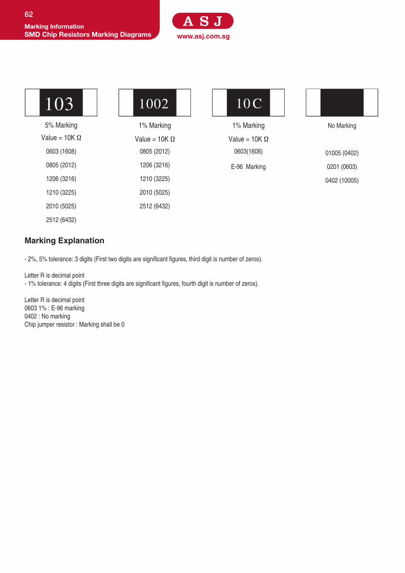
www.asj.com.sg
103 1002 10 C5% Marking 1% Marking 1% Marking No Marking
Value = 10K Ω Value = 10K Ω Value = 10K Ω
0603 (1608) 0805 (2012) 0603(1608) 01005 (0402)
0805 (2012) 1206 (3216) E-96 Marking 0201 (0603)
1206 (3216) 1210 (3225) 0402 (10005)
1210 (3225) 2010 (5025)
2010 (5025) 2512 (6432)
2512 (6432)
Marking Explanation - 2%, 5% tolerance: 3 digits (First two digits are significant figures, third digit is number of zeros).
Letter R is decimal point
- 1% tolerance: 4 digits (First three digits are significant figures, fourth digit is number of zeros).
Letter R is decimal point
0603 1% : E-96 marking
0402 : No marking
Chip jumper resistor : Marking shall be 0
Marking InformationSMD Chip Resistors Marking Diagrams
62

LEADED RESISTORS

www.asj.com.sg
Features
• Available in tolerance 1%, 2% and 5%
• Miniature size series available
• Suitable for automatic machine insertion
• Products with lead free terminations meet EU RoHS and China RoHS
requirements
• Resistors are coated with layers of blue color lacquer
Dimensions and Construction
Ordering Code / Information
Metal Film ResistorsGeneral Purpose Metal Film Resistors
64
-60
20
160 180120 14040 60 80 100 200
120
-40 -20 200
40
60
80
100
Temperature (˚C )
Rat
ed P
ower
(%)
155˚C
70˚C-55˚C
Type (Power Rating)
Dimensions
Inches (Millimeters)
L D I d
MF50(1/6W) 0.134 ± 0.008
(3.40 ± 0.20)
0.075 ± 0.008
(1.90 ± 0.20)
1.102 ± 0.118
(28.00 ± 3.00)
0.018 ± 0.002
(0.45 ± 0.050MF55SS(0.4W)
MF55(1/4W) 0.248 ± 0.020
(6.30 ± 0.50)
0.091 ± 0.012
(2.30 ± 0.30) 0.024 ± 0.002
(0.60 ± 0.05)
MF60SS(0.6W)
MF60(1/2W)
0.354 ± 0.020
(9.00 ± 0.50)
0.130 ± 0.012
(3.30 ± 0.30)
MF65 (1W / T52mm) 0.433 ± 0.040
(11.00 ± 1.00)
0.165 ± 0.020
(4.20 ± 0.50)
1.063 ± 0.118
(27.00 ± 3.00)
0.031 ± 0.002
(0.78 ± 0.05)
MF65(1W / T73mm)
1.378 ± 0.118
(35.00 ± 3.00)
MF70(2W / T73mm)
0.0630 ± 0.040
(16.00 ± 1.00)
0.197 ± 0.020
(5.00 ± 0.50)
1.300 ± 0.118
(33.00 ± 3.00)
MF75(3W / T73mm)
0.670 ± 0.040
(17.00 ± 1.00)
0.236 ± 0.020
(6.00 ± 0.50)
1.378 ± 0.118
(35.00 ± 3.00)
MF 50 - XXXX F - A 5
Type Power Rating Nominal Resistance Resistance Tolerance
Packaging Quantity
General Purpose
Metal Film Resistor
50
55SS
55
60SS
60
65
70
75
Resistors
3-Digit
E24 Series
2.2Ω=2R2
100Ω=101
F =±1%
G =±2%
J =±5%
A = Ammo (52mm)
S = Spool (52mm)
M = Ammo (26mm)
R = Spool (26mm)
N = Ammo (73mm)
Q = Spool (73mm)
1 = 1,000 pcs
2 = 2,000 pcs
3 = 3,000 pcs
5 = 5,000 pcs
4-Digit
E96 Series
10.2Ω=10R2
10KΩ=1002

Specifications given herein may be changed at any time without prior notice. Please confirm technical specifications with factory before use.
www.asj.com.sgMetal Film Resistors
General Purpose Metal Film Resistors
65
Product Type Power Rating @ 70°C
T.C.R (ppm/°C) Max ResistanceRange
E-96, E-24F(±1%), G(±2%),
J(±5%)
Max Working Voltage
Max Overload Voltage
Operating Temperature Range
MF50 1/6W
0.1Ω - 1Ω (±200 ppm)
1Ω - 10Ω (±100 ppm)
10Ω - 1MΩ (±50 ppm)
1MΩ - 2.8MΩ (±100 ppm)
2.8MΩ - 10MΩ (±150 ppm)
1Ω - 10MΩ 250V 500v
-55°C to +155°C
MF55 1/4W
0.1Ω - 10MΩ
300V 600V
MF55SS 0.4W
MF60 1/2W 350V 700V
MF60SS 0.6W 0.1Ω - 1MΩ 300V 600V
MF65 (T52mm) 1W
0.1Ω - 1MΩ 450V 900V
MF65 (T73mm) 1W
MF70 (T73mm) 2W
0.1Ω - 10MΩ
500V
1,000V
MF75 (T73mm) 3W 600V
Test Specification Test Method
Resistance Value Within Resistors specification To be measure at 25°C
Resistance Temperature Coefficient Within Specification of TCR 25°C/ +125°C
Short Time Overload ±(0.5%+0.05Ω) For 1%, 2% & 5% tolerance Apply 2.5 times of rated voltage or maximum overload
voltage for 5 secs which is lower
Resistance to Soldering Heat ±(0.5%+0.05Ω) For 1%, 2% & 5% tolerance 260°C ± 5°C, 10 seconds ± 1 second
Moisture Resistance ±(1%+0.05Ω) For 1% , 2% & 5% tolerance resistor 40°C ± 2°C, 90% - 95% RH, 1000 hours
Load Life ±(1.0%+0.05Ω) For 1%, 2% & 5% tolerance 70°C ± 2°C ,1000 hours, 1.5 hours On,0.5 hours Off cycle
Application and Ratings

www.asj.com.sg
Features
• Available in tolerance 0.1% and 0.5%
• Miniature size series available
• Suitable for automatic machine insertion
• Products with lead free terminations meet EU RoHS and China RoHS
requirements
• Resistors are coated with layers of blue color lacquer
Dimensions and Construction
Ordering Code / Information
Metal Film ResistorsPrecision Metal Film Resistors
66
-60 120 14040 60 80 100
80
100
20
160 180 200
120
-40 -20 200
40
60
Temperature (˚C )
Rat
ed P
ower
(%)
155˚C
70˚C-55˚C
Type(Power Rating)
Dimensions
Inches (Millimeters)
L D I d
MF50(1/6W) 0.134 ± 0.008
(3.40 ± 0.20)
0.075 ± 0.008
(1.90 ± 0.20)
1.102 ± 0.118
(28.00 ± 3.00)
0.018 ± 0.002
(0.45 ± 0.050MF55SS(0.4W)
MF55(1/4W) 0.248 ± 0.020
(6.30 ± 0.50)
0.091 ± 0.012
(2.30 ± 0.30) 0.024 ± 0.002
(0.60 ± 0.05)
MF60SS(0.6W)
MF60(1/2W)
0.354 ± 0.020
(9.00 ± 0.50)
0.130 ± 0.012
(3.30 ± 0.30)
MF65 (1W / T52mm) 0.433 ± 0.040
(11.00 ± 1.00)
0.165 ± 0.020
(4.20 ± 0.50)
1.063 ± 0.118
(27.00 ± 3.00)
0.031 ± 0.002
(0.78 ± 0.05)
MF65(1W / T73mm)
1.378 ± 0.118
(35.00 ± 3.00)
MF70(2W / T73mm)
0.0630 ± 0.040
(16.00 ± 1.00)
0.197 ± 0.020
(5.00 ± 0.50)
1.300 ± 0.118
(33.00 ± 3.00)
MF75(3W / T73mm)
0.670 ± 0.040
(17.00 ± 1.00)
0.236 ± 0.020
(6.00 ± 0.50)
1.378 ± 0.118
(35.00 ± 3.00)
MF 50 - XXXX F - A 5
Type Size Nominal Resistance Resistance Tolerance
Packaging Quantity
Precision Metal Film
Resistors
50
55
55SS
60
60SS
65
70
75
Resistors
3-Digit
E24 Series
2.2Ω=2R2
100Ω=101
B = ±0.1%
D = ±0.5%
A = Ammo (52mm)
S = Spool (52mm)
M = Ammo (26mm)
N = Ammo (73mm)
Q = Spool (73mm)
1 = 1,000 pcs
2 = 2,000 pcs
3 = 3,000 pcs
5 = 5,000 pcs
4-Digit
E96 Series
10.2Ω=10R2
10KΩ=1002

Specifications given herein may be changed at any time without prior notice. Please confirm technical specifications with factory before use.
www.asj.com.sgMetal Film Resistors
Precision Metal Film Resistors
67
Product Type Power Rating @ 70°C
T.C.R (ppm/°C) Max ResistanceRange
E-96, E-24F(±1%),
G(±2%), J(±5%)
Max Working Voltage
Max Overload Voltage
Operating Temperature Range
MF50 1/6W
0.1Ω - 1Ω (±200ppm)
1Ω - 10Ω (±100ppm)
10Ω - 1MΩ (±50ppm)
1MΩ - 2.8MΩ (±100ppm)
2.8MΩ - 10MΩ (±150ppm)
1Ω - 10MΩ 250V 500v
-55°C to +155°C
MF55 1/4W
0.1Ω - 10MΩ
300V 600V
MF55SS 0.4W
MF60 1/2W 350V 700V
MF60SS 0.6W 0.1Ω - 1MΩ 300V 600V
MF65 (T52mm) 1W
0.1Ω - 1MΩ 450V 900V
MF65 (T73mm) 1W
MF70 (T73mm) 2W
0.1Ω - 10MΩ
500V
1,000V
MF75 (T73mm) 3W 600V
Test Specification Test Method
Resistance Value Within Resistors specification To be measure at 25°C
Resistance Temperature Coefficient Within Specification of TCR 25°C/ +125°C
Short Time Overload ±(0.5%+0.05Ω) For 1%, 2% & 5% tolerance Apply 2.5 times of rated voltage or maximum overload voltage for
5 secs which is lower
Resistance to Soldering Heat ±(0.5%+0.05Ω) For 1%, 2% & 5% tolerance 260°C ± 5°C, 10 seconds ± 1 second
Moisture Resistance ±(1.0%+0.05Ω) for 1% , 2% & 5% tolerance resistor 40°C ± 2°C, 90% - 95% RH, 1000 hours
Load Life ±(1.0%+0.05Ω) For 1%, 2% & 5% tolerance 70 °C ± 2°C ,1000 hours, 1.5 hours On,0.5 hours Off cycle
High Temperature Exposure ±(0.5%+0.05Ω) For 1% tolerance 125°C , 1000 hours. Unpowered. Measurement at 24 ± 2 hours after
test conclusion.±(1.0%+0.05Ω) For 2% & 5% tolerance
Application and Ratings

www.asj.com.sg
Features
• Available in tolerance 1%, 2% and 5%
• Miniature size series available
• Suitable for automatic machine insertion
• Products with lead free terminations meet EU RoHS and China RoHS
requirements
• Resistors are coated with layers of blue color lacquer
Dimensions and Construction
Ordering Code / Information
Metal Film ResistorsHigh Precision Metal Film Resistors
68
-60 120 14040 60 80 100
80
100
20
160
120
-40 -20 200
40
60
Temperature (˚C )
Rat
ed L
oad
(%)
155˚C
70˚C
Type(Power Rating)
Dimensions
Inches (Millimeters)
L D I d
MF55(1/4W)
0.244 ± 0.012
(6.20 ± 0.30)
0.071 ± 0.012
(1.80 ± 0.30)
1.417 ± 0.079
(36.00 ± 2.00) 0.025 ± 0.002
(0.63 ± 0.05)MF60(1/2W)
0.358 ± 0.012
(9.10 ± 0.30)
0.083 ± 0.012
(2.10 ± 0.30)
1.417 ± 0.118
(36.00 ± 3.00)
MF - 50 - XXXX F - A 5
Type Size Nominal Resistance Resistance Tolerance
Packaging Quantity
High Precision
Metal Film
Resistors
55
60
Resistors 4-Digit
E192 Series
10.2Ω=10R2
10KΩ=1002
Q = ±0.02%
A = ±0.05%
A = Ammo (52mm)
S = Spool (52mm)
M = Ammo (26mm)
N = Ammo (73mm)
Q = Spool (73mm)
1 = 1,000 pcs
2 = 2,000 pcs
3 = 3,000 pcs
5 = 5,000 pcs

Specifications given herein may be changed at any time without prior notice. Please confirm technical specifications with factory before use.
www.asj.com.sgMetal Film Resistors
High Precision Metal Film Resistors
69
Product Type Power Rating @ 70°C
T.C.R (ppm/°C) Max ResistanceRangeE192
Q(±0.02%), A(±0.05%)
Max Working Voltage
Max Overload Voltage
Operating Temperature Range
MF50 1/4W ±5 ppm
±10 ppm100Ω - 500KΩ
200V 400V
-55°C to +150°C
MF60 1/2W 250V 500V
Test Specification Test Method
Resistance Value Within Resistors specification To be measure at 25°C
Resistance Temperature Coefficient Within Specification of TCR 25°C/ +125°C
Short Time Overload ±(0.25%+0.05Ω) For 0.02% & 0.05% tolerance Apply 2.5 times of rated voltage or maximum overload
voltage for 5secs which is lower
Resistance to Soldering Heat ±(0.1%+0.05Ω) For 0.02% & 0.05% tolerance 260°C ± 10°C, 3 seconds ± 0.5 second
Moisture Resistance ±(0.5%+0.05Ω) For 0.02% & 0.05% tolerance resistor 40°C ± 2°C, 90% - 95% RH, 1000 hours
Load Life ±(0.5%+0.05Ω) For 0.02% & 0.05% tolerance 70°C ± 2°C ,1000hours, 1.5 hours On,0.5 hours Off cycle
Application and Ratings

www.asj.com.sg
Features
• Flame-proof lacquer coating insulation
• Suitable for automatic machine insertion
• Resistors are coated with layers of blue color lacquer
Dimensions and Construction
Ordering Code / Information
Metal Film ResistorsFlame-Proof Metal Film Resistors
70
160 180 200
120
-40 -20 200
40
60
120 14040 60 80 100
80
100
20
0
Temperature (˚C )
Rat
ed P
ower
(%)
155˚C
70˚C-55˚C
Dimensions
Type Inches (Millimeters)
L D l d
FM50(1/6W) 0.126 ± 0.020
(3.20 ± 0.50)
0.075 ± 0.020
(1.90 ± 0.50)
1.102 ± 0.079
(0.28 ± 2.00)0.018 ± 0.002 (0.45 ± 0.05)
FM55SS(0.4W)
FM55(1/4W) 0.244 ± 0.020
(6.20 ± 0.50)
0.091 ± 0.020
(2.30 ± 0.50) 1.063 ± 0.079
(27.00 ± 2.00)0.022 ± 0.002 (0.55 ± 0.05)
FM60SS(0.6W)
FM60(1/2W)
0.358 ± 0.020
(9.10 ± 0.50)
0.126 ± 0.020
(3.20 ± 0.50)
FM65(1W)
0.441 ± 0.020
(11.20 ± 0.50)
0.165 ± 0.020
(4.20 ± 0.50) 1.339 ± 0.079
(34.00 ± 2.00)0.031 ± 0.002 (0.78 ± 0.05)
FM70(2W)
0.598 ± 0.020
(15.20 ± 0.50)
0.197 ± 0.020
(5.00 ± 0.50)
FM 50 - XXXX F - A 5
Type Power Rating Nominal Resistance Resistance Tolerance
Packaging Quantity
Flame-Proof Metal
Film Resistors
50
55
55SS
60
60SS
65
70
Resistors
3-Digit
E24 Series
2.2Ω=2R2
100Ω=101
F = ±1%
G = ±2%
J = ±5%
A = Ammo (52mm)
S = Spool (52mm)
M = Ammo (26mm)
R = Spool (26mm)
N = Ammo (73mm)
Q = Spool (73mm)
1 = 1,000 pcs
2 = 2,000 pcs
3 = 3,000 pcs
5 = 5,000 pcs
4-Digit
E96 Series
10.2Ω=10R2
10KΩ=1002

Specifications given herein may be changed at any time without prior notice. Please confirm technical specifications with factory before use.
www.asj.com.sgMetal Film Resistors
Flame-Proof Metal Film Resistors
71
Product Type Power Rating @ 70°C
T.C.R (ppm/°C) Max ResistanceRange
E-96, E-24 F(± 1%), G(± 2%),
J(± 5%)
Max Working Voltage Max Overload Voltage Operating Temperature Range
FM50 1/6W
> 10Ω (±50 ppm)
< 10Ω (±100 ppm)1Ω - 1MΩ
200V 400V
-55°C to +155°C
FM55 1/4W
250V 500V
FM55SS 0.4W
FM60 1/2W
350V
700VFM60SS 0.6W
FM65 1W
500V
FM70 2W 1,000V
Test Specification Test Method
Resistance Value Within Resistors specification To be measure at 25°C
Resistance Temperature Coefficient Within Specification of TCR 25°C/ +125°C
Short Time Overload ±(0.5% + 0.05Ω) For 1%, 2% & 5% tolerance Apply 2.5 times of rated voltage or maximum overload
voltage for 5 secs which is lower
Resistance to Soldering Heat ±(0.5% + 0.05Ω) For 1%, 2% & 5% tolerance 350°C ± 10°C, 3 seconds ± 0.5 second
Moisture Resistance ±(3.0% + 0.05Ω) For 1% , 2% & 5% tolerance 40°C ± 2°C, 90% - 95% RH, 1000 hours
Load Life ±(5.0% + 0.05Ω) Max For 1%, 2% & 5% tolerance 70°C ± 2°C ,1000 hours, 1.5 hours On,0.5 hours Off cycle
Application and Ratings

www.asj.com.sg
Features
• Small size, High power
• Flame-proof multi-layer coating meets UL-94V-0
• Resistors are coated with layers of pink color lacquer
Dimensions and Construction
Ordering Code / Information
Metal Film ResistorsHigh Power Flame-Proof Metal Film Resistors
72
160 180 200
120
-40 -20 200
40
60
120 14040 60 80 100
80
100
20
0
Temperature (˚C )
Rat
ed P
ower
(%)
155˚C
70˚C
-55˚C
Type(Power Rating)
Dimensions
Inches (Millimeters)
L D I d
FMP60SS(1/2W)
0.134 ± 0.012
(3.40 ± 0.30)
0.075 ± 0.008
(1.90 ± 0.20) 1.102 ± 0.079
(28.00 ± 2.00)
0.018 ± 0.002
(0.45 ± 0.05)
FMP65SS(1W)
0.248 ± 0.020
(6.30 ± 0.50)
0.094 ± 0.008
(2.40 ± 0.20) 0.022 ± 0.002
(0.55 ± 0.05)FMP70SS(2W)
0.354 ± 0.020
(9.00 ± 0.50)
0.154 ± 0.012
(3.90 ± 0.30)
1.024 ± 0.079
(26.00 ± 2.00)
FMP75SS(3W)
0.453 ± 0.040
(11.50 ± 1.00)
0.177 ± 0.020
(4.50 ± 0.50)
1.378 ± 0.079
(35.00 ± 2.00)
0.031 ± 0.002
(0.80 ± 0.05)
FMP75(3W)
0.610 ± 0.040
(15.50 ± 1.00)
0.197 ± 0.020
(5.00 ± 0.50)
1.300 ± 0.079
(33.00 ± 2.00)
FMP80SS(4W)
0.670 ± 0.040
(17.00 ± 1.00)
0.295 ± 0.020
(7.50 ± 0.50)
1.260 ± 0.079
(32.00 ± 2.00)
FMP 60SS - XXXX F - A 1
Type Power Rating Nominal Resistance Resistance Tolerance
Packaging Quantity
High Power
Flame-Proof
Metal Film
Resistor
60SS
65SS
70SS
75SS
75
80SS
Resistors
3-Digit
E24 Series
2.2Ω=2R2
100Ω=101
F = ±1%
J = ±5%
A = Ammo (52mm)
S = Spool (52mm)
M = Ammo (26mm)
R = Spool (26mm)
N = Ammo (73mm)
Q = Spool (73mm)
500 = 500 pcs
1 = 1,000 pcs
4-Digit
E96 Series
10.2Ω=10R2
10KΩ=1002

Specifications given herein may be changed at any time without prior notice. Please confirm technical specifications with factory before use.
www.asj.com.sgMetal Film Resistors
High Power Flame-Proof Metal Film Resistors
73
Product Type Power Rating @ 70°C
T.C.R (ppm/°C) Max
ResistanceRange
E-24, E-96 F(±1%), J(±5%)
Max Working Voltage Max Overload Voltage
Operating Temperature Range
FMP60SS 1/2W
±100 1Ω - 10MΩ
200V 400V
-55°C to +155°C
FMP65SS 1W 350V 600V
FMP70SS 2W
500V 700V
FMP75SS3W
FMP75750V 1,000V
FMP80 4W
Test Specification Test Method
Resistance Value Within Resistors specification To be measure at 25°C
Resistance Temperature Coefficient Within Specification of TCR 25°C/ +125°C
Short Time Overload ±(0.5% + 0.05Ω) For 1% & 5% tolerance Apply 2.5 times of rated voltage or maximum overload voltage for
5 secs which is lower
Resistance to Soldering Heat ± (0.25% + 0.05Ω) For 1% & 5% tolerance 260°C ± 5°C, 10 seconds ± 1 second
Moisture Resistance ±(2.0% + 0.05Ω) For 1% & 5% tolerance 40°C ± 2°C, 90% - 95% RH, 1000 hours
Load Life ±(2.0% + 0.05Ω) For 1% & 5% tolerance 70°C ± 2°C ,1000 hours, 1.5 hours On,0.5 hours Off cycle
Application and Ratings

www.asj.com.sg
Features
• Function as a metal film resistors and when in presence of abnormal current,
fusing capabilities activated to protect machine or equipment
• Saves the cost of having a fuse on PCB, hence increase cost savings
• Excellent TCR and reliable.
• Flameproof feature meets UL-1412 standard
• Flameproof coating meets UL-94V-0 standard
• Resistors are coated with layers of grey color lacquer
• FSR2SS is coated with layers of pink color lacquer
Dimensions and Construction
Ordering Code / Information
Metal Film ResistorsFusible Metal Film Resistors
74
120
-40 -20 200
40
60
80
100
20
0160120 14040 60 80 100
Temperature (˚C )
Rat
ed L
oad
(%)
155˚C
70˚C-55˚C
Dimensions
Type Inches (Millimeters)
L D I d
FSR1/4(1/4W) 0.244 ± 0.040
(6.20 ± 1.00)
0.087 ± 0.040
(2.30 ± 1.00)
1.063 ± 0.079
(27.00 ± 2.00)
0.022 ± 0.002
(0.55 ± 0.05)
FSR1/2SS(1/2W)
FSR1/2(1/2W) 0.358 ± 0.040
(9.10 ± 1.00)
0.126 ± 0.040
(3.20 ± 1.00)FSR1SS(1W)
FSR1(1W) 0.441 ± 0.040
(11.20 ± 1.00)
0.065 ± 0.040
(4.20 ± 1.00)
1.024 ± 0.079
(26.00 ± 2.00)
0.031 ± 0.002
(0.78 ± 0.05)
FSR2SS(2W)
FSR2(2W) 0.598 ± 0.040
(15.20 ± 1.00)
0.197 ± 0.040
(5.00 ± 1.00)
1.260 ± 0.079
(32.0 ± 2.00)FSR3SS(3W)
FSR 1/4 - XXX J - A 5
Type Power Rating Nominal Resistance Resistance Tolerance
Packaging Quantity
Fusible Metal Film
Resistors
1/4
1/2
1/2SS
1
1SS
2
2SS
3SS
Resistors
3-Digit
E24 Series
2.2Ω=2R2
100Ω=101
F = ±1%
G = ±2%
J = ±5%
A = Ammo (52mm)
S = Spool (52mm)
M = Ammo (26mm)
N = Ammo (73mm)
Q = Spool (73mm)
1 = 1,000 pcs
2 = 2,000 pcs
5 = 5,000 pcs
4-Digit
E96 Series
10.2Ω=10R2
10KΩ=1002

Specifications given herein may be changed at any time without prior notice. Please confirm technical specifications with factory before use.
www.asj.com.sg
FSR 1/4 - XXX J - A 5
Type Power Rating Nominal Resistance Resistance Tolerance
Packaging Quantity
Fusible Metal Film
Resistors
1/4
1/2
1/2SS
1
1SS
2
2SS
3SS
Resistors
3-Digit
E24 Series
2.2Ω=2R2
100Ω=101
F = ±1%
G = ±2%
J = ±5%
A = Ammo (52mm)
S = Spool (52mm)
M = Ammo (26mm)
N = Ammo (73mm)
Q = Spool (73mm)
1 = 1,000 pcs
2 = 2,000 pcs
5 = 5,000 pcs
4-Digit
E96 Series
10.2Ω=10R2
10KΩ=1002
Metal Film ResistorsFusible Metal Film Resistors
75
Product Type Power Rating @ 70°C
T.C.R (ppm/°C) Tolerance (±1%)
T.C.R (ppm/°C) Tolerance (±2%,
±5%)
ResistanceRange
E96 and E-24F(±1%),G(±2%),
J(±5%)
Max Working Voltage
Max Overload Voltage
Operating Temperature
Range
FSR1/4 1/4W
< 10Ω (±200 ppm)
≥ 10Ω (±100 ppm)
< 10Ω (±400 ppm)
≥ 10Ω (±200 ppm)1Ω - 2KΩ
250V 500V
-55°C to +155°C
FSR1/21/2W
350V 600V
FSR1/2SS 250V 500V
FSR11W
350V 600V
FSR1SS 350V 600V
FSR22W
500V 600V
FSR2SS 350V 600V
FSR3SS 3W 350V 600V
Test Specification Test Method
Resistance Value Within Resistors specification To be measure at 25°C
Resistance Temperature Coefficient Within Specification of TCR 25°C/ +125°C
Short Time Overload ±(2.0% + 0.05Ω) For 2% & 5% tolerance Apply 2.5 times of rated voltage or maximum overload voltage
for 5 secs which is lower
Resistance to Soldering Heat ±(1.0% + 0.05Ω) For 2% & 5% tolerance 260°C ± 5°C, 10 seconds ± 1 second
Moisture Resistance ±(5.0% + 0.05Ω) For 2% & 5% tolerance 40°C ± 2°C, 90% - 95% RH, 1000 hours
Load Life ±(5.0% + 0.05Ω) For 2% & 5% tolerance 70°C ± 2°C ,1000 hours, 1.5 hours On,0.5 hours Off cycle
Clearing time current test a) Open within 30 secs at 4 times rated voltage ( 1 Ω and
above)
Resistor fusing without flaming and arcing
b) Open within 30 secs at 5 times rated voltage
(below 1 Ω)
Application and Ratings

www.asj.com.sg
Features
• Highly reliable multi-layer electrode construction.
• Compatible with wave and reflow soldering process.
• Pb Free with Reflow soldering backward compatibility
• Resistors are coated with layers of beige color lacquer
• CF 1/2SS resistors are coated with layers of pink color lacquer
Dimensions and Construction
Ordering Code / Information
Carbon Film ResistorsGeneral Purpose Carbon Film Resistors
76
Type(Power Rating)
Dimensions
Inches (Millimeters)
L D I d
CF 1/6(1/6W) 0.134 ± 0.008
(3.40 ± 0.20)
0.075 ± 0.008
(1.90 ± 0.20)
1.102 ± 0.118
(28.00 ± 3.00)
0.018 ± 0.002
(0.45 ± 0.05)CF1/4SS(1/4W)
CF1/4(1/4W) 0.248 ± 0.020
(6.30 ± 0.50)
0.091 ± 0.012
(2.30 ± 0.30) 0.024 ± 0.002
(0.60 ± 0.05)
CF1/2SS(1/2W)
CF1/2(1/2W) 0.354 ± 0.020
(9.00 ± 0.50)
0.130 ± 0.012
(3.30 ± 0.30)
1.102 ± 0.118
(28.00 ± 3.00)CF1SS(1W)
0.031 ± 0.002
(0.78 ± 0.05)
CF1(1W / T52mm)
0.433 ± 0.040
(11.00 ± 1.00)
0.165 ± 0.020
(4.20 ± 0.50)
1.063 ± 0.118
(27.00 ± 3.00)
0.031 ± 0.002
(0.78 ± 0.05)
CF1(1W / T73mm)
1.378 ± 0.118
(35.00 ± 3.00)
CF2SS(2W / T52mm)
1.063 ± 0.118
(27.00 ± 3.00)
CF2SS(2W / T73mm)
1.378 ± 0.118
(35.00 ± 3.00)
CF2(2W)
0.610 ± 0.040
(15.50 ± 1.00)
0.197 ± 0.020
(5.00 ± 0.50) 1.300 ± 0.118
(33.00 ± 3.00)CF3(3W)
0.591 ± 0.040
(15.00 ± 1.00)
0.197 ± 0.020
(5.00 ± 0.50)
CF 1/6 - XXX J - A 5
Type Power Rating Nominal Resistance Resistance Tolerance
Packaging Quantity
General Purpose
Carbon Film
Resistor
1/6
1/4
1/4SS
1/2
1/2SS
1
1SS
2
2SS
3
Resistors 3-Digit
E24 Series
2.2Ω=2R2
100Ω=101
G = ±2%
J = ±5%
A = Ammo (52mm)
S = Spool (52mm)
M = Ammo (26mm)
N = Ammo (73mm)
Q = Spool (73mm)
05 = 500 pcs
1 = 1,000pcs
2 = 2,000pcs
3 = 3,000pcs
5 = 5,000pcs
0250
120
-50 -25 250
40
60
80
100
20
275150 17550 75 100 125 225200
Temperature (˚C )
Rat
ed P
ower
(%)
70˚-55˚C
275˚

Specifications given herein may be changed at any time without prior notice. Please confirm technical specifications with factory before use.
www.asj.com.sgCarbon Film Resistors
General Purpose Carbon Film Resistors
77
Product Type Power Rating @ 70°C
T.C.R (ppm/°C) Max ResistanceRangeE-24
G(±2%)
ResistanceRangeE-24
J(±5%)
Max Working Voltage
Max Overload Voltage
Operating Temperature Range
CF 1/6 1/6W
<10Ω (±300 ppm)
10Ω ≤ X ≤ 50KΩ (0 to -350 ppm)
50KΩ < X ≤ 430KΩ (0 to -500 ppm)
430KΩ < X ≤ 1MΩ (0 to -800 ppm)
1MΩ < X ≤ 4.7MΩ (0 to -1,600 ppm)
4.7MΩ < X ≤ 10MΩ (0 to -2,000 ppm)
1Ω - 1MΩ
1Ω - 10MΩ
250V
400V
-55°C to +155°C
CF 1/41/4W 500V
CF1/4SS
CF1/21/2W 350V 700V
CF1/2SS
CF11W
500V 1000V
CF1SS
CF22W
10Ω - 1MΩCF2SS
CF3 3W
Test Specification Test Method
Resistance Value Within Resistors specification To be measure at 25°C
Resistance Temperature Coefficient Within Specification of TCR 25°C/ +125°C
Short Time Overload ±(0.5% + 0.05Ω) For 2% & 5% tolerance Apply 2.5 times of rated voltage or maximum overload voltage for
5 secs which is lower
Resistance to Soldering Heat ±(0.5% + 0.05Ω) For 2% & 5% tolerance 260°C ± 5°C, 10 seconds ± 1 second
Moisture Resistance ±(1.0% + 0.05Ω) For 2% & 5% tolerance 40°C ± 2°C, 90% - 95% RH, 1000 hours
Load Life < 100KΩ, ±2% Max. For 2% & 5% tolerance 70 °C ± 2°C ,1000 hours, 1.5 hours On, 0.5 hours Off cycle
≥ 100KΩ, ±3% Max.
Application and Ratings
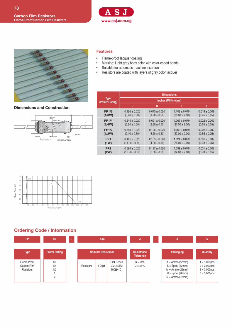
www.asj.com.sg
Features
• Flame-proof lacquer coating
• Marking: Light gray body color with color-coded bands
• Suitable for automatic machine insertion
• Resistors are coated with layers of gray color lacquer
Dimensions and Construction
Ordering Code / Information
Carbon Film ResistorsFlame-Proof Carbon Film Resistors
78
Type(Power Rating)
Dimensions
Inches (Millimeters)
L D l d
FP1/6(1/6W)
0.126 ± 0.020
(3.20 ± 0.50)
0.075 ± 0.020
(1.90 ± 0.50)
1.102 ± 0.079
(28.00 ± 2.00)
0.018 ± 0.002
(0.45 ± 0.05)
FP1/4(1/4W)
0.244 ± 0.020
(6.20 ± 0.50)
0.091 ± 0.020
(2.30 ± 0.50)
1.063 ± 0.079
(27.00 ± 2.00)
0.022 ± 0.002
(0.55 ± 0.05)
FP1/2(1/2W)
0.358 ± 0.020
(9.10 ± 0.50)
0.126 ± 0.020
(3.20 ± 0.50)
1.063 ± 0.079
(27.00 ± 2.00)
0.022 ± 0.002
(0.55 ± 0.05)
FP1(1W)
0.441 ± 0.020
(11.20 ± 0.50)
0.165 ± 0.020
(4.20 ± 0.50)
1.024 ± 0.079
(26.00 ± 2.00)
0.031 ± 0.002
(0.78 ± 0.05)
FP2(2W)
0.598 ± 0.020
(15.20 ± 0.50)
0.197 ± 0.020
(5.00 ± 0.50)
1.339 ± 0.079
(34.00 ± 2.00)
0.031 ± 0.002
(0.78 ± 0.05)
160 180 200
120
-40 -20 200
40
60
120 14040 60 80 100
80
100
20
0
Temperature (˚C )
Rat
ed P
ower
(%)
155˚C
70˚C
-55˚C
FP 1/6 - XXX J - A 5
Type Power Rating Nominal Resistance Resistance Tolerance
Packaging Quantity
Flame-Proof
Carbon Film
Resistors
1/6
1/4
1/2
1
2
Resistors 3-Digit
E24 Series
2.2Ω=2R2
100Ω=101
G = ±2%
J = ±5%
A = Ammo (52mm)
S = Spool (52mm)
M = Ammo (26mm)
R = Spool (26mm)
N = Ammo (73mm)
1 = 1,000pcs
2 = 2,000pcs
3 = 3,000pcs
5 = 5,000pcs

Specifications given herein may be changed at any time without prior notice. Please confirm technical specifications with factory before use.
www.asj.com.sgCarbon Film Resistors
Flame-Proof Carbon Film Resistors
79
Product Type Power Rating @ 70°C
T.C.R (ppm/°C) Max ResistanceRangeE-24
G(±2%)
ResistanceRangeE-24
J(±5%)
Max Working Voltage
Max Overload Voltage
Operating Temperature Range
FP1/6 1/6W
10Ω - 1MΩ 1Ω - 10MΩ
200V 400V
-55°C to +155°C
FP1/4 1/4W
<10Ω (±300 ppm)
250V 500V
10Ω ≤ X ≤ 50KΩ (0 to -350 ppm)
FP1/2 1/2W
50KΩ < X ≤ 430KΩ (0 to -500 ppm)
350V 700V
430KΩ < X ≤ 1MΩ (0 to -800 ppm)
FP1 1W
1MΩ < X ≤ 4.7MΩ (0 to -1,600 ppm)
500V 1,000V
4.7MΩ < X ≤ 10MΩ (0 to -2,000 ppm)
FP2 2W
Test Specification Test Method
Resistance Value Within Resistors specification To be measure at 25°C
Resistance Temperature Coefficient Within Specification of TCR 25°C/ +125°C
Short Time Overload ±(1.0% + 0.05Ω) For 2% & 5% tolerance Apply 2.5 times of rated voltage or maximum overload voltage for
5 secs which is lower
Resistance to Soldering Heat ±(1.0% + 0.05Ω) For 2% & 5% tolerance 260°C ± 5°C, 10 seconds ± 1 second
Moisture Resistance ±(1.0% + 0.05Ω) For 2% & 5% tolerance 40°C ± 2°C, 90% - 95% RH, 1000 hours
Load Life ±(2.0% + 0.1Ω) For 2% & 5% tolerance 70°C ± 2°C ,1000 hours, 1.5 hours On,0.5 hours Off cycle
High Temperature Exposure ±(1.0% + 0.05Ω) For 2% & 5% tolerance 125°C , 1000 hours. Unpowered. Measurement at 24 ± 2 hours
after test conclusion
Application and Ratings

www.asj.com.sg
Features
• Flame-proof silicone coating equivalent to UL94V0
• Suitable for automatic machine insertion
• High reliability for performance
• Standard size resistors are coated with layers of grey color lacquer
• Miniature size resistors are coated with layers of pink color lacquer
Dimensions and Construction
Ordering Code / Information
Metal Oxide ResistorsFlame-Proof Metal Oxide Resistors
80
Type(Power Rating)
Dimensions
Inches (Millimeters)
L D l d
MO1/4(1/4W) 0.248 ± 0.020
(6.30 ± 0.50)
0.091 ± 0.012
(2.30 ± 0.30)
1.102 ± 0.118
(28.00 ± 3.00)
0.024 ± 0.002
(0.60 ± 0.05)
MO1/2SS(1/2W)
MO1/2(1/2W) 0.354 ± 0.020
(9.00 ± 0.50)
0.26 ± 0.020
(3.20 ± 0.50)
1.063 ± 0.118
(27.00 ± 3.00)MO1SS(1W)
MO1(1W) 0.433 ± 0.040
(11.00 ± 1.00)
0.169 ± 0.020
(4.30 ± 0.50)
1.378 ± 0.118
(35.00 ± 3.00)
0.031 ± 0.002
(0.78 ± 0.05)
MO2SS(2W)
MO2(2W) 0.630 ± 0.040
(16.00 ± 1.00)
0.197 ± 0.020
(5.00 ± 0.50) 1.260 ± 0.118
(32.00 ± 3.00)
MO3SS(3W)
MO3(3W)
0.669 ± 0.040
(17.00 ± 1.00)
0.236 ± 0.040
(6.00 ± 1.00)
MO5SS(5W) 0.984 ± 0.079
(25.00 ± 2.00)
0.335 ± 0.040
(8.50 ± 1.00)
1.496 ± 0.118
(38.00 ± 3.00)MO5(5W)
MO 1/4 - XXXX J - A 5
Type Power Rating Nominal Resistance Resistance Tolerance
Packaging Quantity
Flame-Proof Metal
Oxide Resistors
1/4
1/2
1/2SS
1
1SS
2
2SS
3
3SS
5
5SS
Resistors 3-Digit
E24 Series
2.2Ω=2R2
100Ω=101
G = ±2%
J = ±5%
A = Ammo (52mm)
S = Spool (52mm)
M = Ammo (26mm)
R = Spool (26mm)
N = Ammo (73mm)
Q = Spool (73mm)
B = Bulk
025 = 250 pcs
05 = 500 pcs
1 = 1,000pcs
2 = 2,000pcs
3 = 3,000pcs
5 = 5,000pcs
0250
120
-50 -25 250
40
60
80
100
20
275150 17550 75 100 125 225200
Temperature (˚C )
Rat
ed P
ower
(%)
70˚-55˚C
275˚

Specifications given herein may be changed at any time without prior notice. Please confirm technical specifications with factory before use.
www.asj.com.sg
MO 1/4 - XXXX J - A 5
Type Power Rating Nominal Resistance Resistance Tolerance
Packaging Quantity
Flame-Proof Metal
Oxide Resistors
1/4
1/2
1/2SS
1
1SS
2
2SS
3
3SS
5
5SS
Resistors 3-Digit
E24 Series
2.2Ω=2R2
100Ω=101
G = ±2%
J = ±5%
A = Ammo (52mm)
S = Spool (52mm)
M = Ammo (26mm)
R = Spool (26mm)
N = Ammo (73mm)
Q = Spool (73mm)
B = Bulk
025 = 250 pcs
05 = 500 pcs
1 = 1,000pcs
2 = 2,000pcs
3 = 3,000pcs
5 = 5,000pcs
Metal Oxide ResistorsFlame-Proof Metal Oxide Resistors
81
Product Type Power Rating @ 70°C
T.C.R (ppm/°C) Max
ResistanceRangeE-24
G(±2%), J(±5%)
Max Working Voltage Max Overload Voltage
Operating Temperature Range
MO1/4 1/4W
±350 0.1Ω - 100KΩ
250V
400V
-55°C to +275°C
MO1/21/2W 500V
MO1/2SS
MO11W
350V
700V
MO1SS
MO22W
MO2SS500V
MO33W
MO3SS 350V
MO55W 500V 1000V
MO5SS
Test Specification Test Method
Resistance Value Within Resistors specification To be measure at 25°C
Resistance Temperature Coefficient Within Specification of TCR 25°C/ +125°C
Short Time Overload ±(0.5%+0.05Ω) For 2% & 5% tolerance Apply 2.5 times of rated voltage or maximum overload voltage for
5 secs which is lower
Resistance to Soldering Heat ±(0.5%+0.05Ω) For 2% & 5% tolerance 260°C ± 5°C, 10 seconds ± 1 second
Moisture Resistance ±(3.0%+0.05Ω) For 2% & 5% tolerance 40°C ± 2°C, 90% - 95% RH, 1000 hours
Load Life ±(3.0%+0.05Ω) For 2% & 5% tolerance 70°C ± 2°C ,1000 hours, 1.5 hours On, 0.5 hours Off cycle
Application and Ratings

www.asj.com.sg
Features
• Metal Glaze film element are coated to solid ceramic core
• Excellent pulse loading capabilities
• Suitable for automatic machine insertion
• Resistors are coated with layers of blue color lacquer
Dimensions and Construction
Ordering Code / Information
Metal Glaze ResistorsPulse Loading Metal Glaze Resistors
82
20
0160 180120 14040 60 80 100 200
120
-40 -20 200
40
60
80
100
Temperature (°C)
Rat
ed P
ower
(%)
155°C
70°C
-55°C
Dimensions
Type Inches (Millimeters)
L D I d
MGP1/4(1/4W) 0.248 ± 0.020
(6.30 ± 0.50)
0.094 ± 0.008
(2.40 ± 0.20)
1.102 ± 0.079
(28.00 ± 2.00) 0.022 ± 0.002
(0.55 ± 0.05)
MGP1/2SS(1/2W)
MGP1/2(1/2W)
0.354 ± 0.020
(9.00 ± 0.50)
0.130 ± 0.012
(3.30 ± 0.30)
1.024 ± 0.079
(26.00 ± 2.00)
MGP1(1W)
0.453 ± 0.040
(11.50 ± 1.00)
0.177 ± 0.020
(4.50 ± 0.50)
1.378 ± 0.079
(35.00 ± 2.00) 0.031 ± 0.002
(0.80 ± 0.05)MGP2(2W)
0.610 ± 0.040
(15.50 ± 1.00)
0.197 ± 0.02 (5.00
± 0.50)
1.300 ± 0.079
(33.00 ± 2.00)
MGP 1/4 - XXX J - A 5
Type Power Rating Nominal Resistance Resistance Tolerance
Packaging Quantity
Pulse Loading
Metal Glaze
Resistor
1/4
1/2
1/2SS
1
2
Resistors 3-Digit
E24 Series
2.2Ω=2R2
100Ω=101
J - 5%
A = Ammo (52mm)
S = Spool (52mm)
M = Ammo (26mm)
R = Spool (26mm)
N = Ammo (73mm)
Q = Spool (73mm)
1 - 1,000pcs
5 - 5,000pcs

Specifications given herein may be changed at any time without prior notice. Please confirm technical specifications with factory before use.
www.asj.com.sgMetal Glaze Resistors
Pulse Loading Metal Glaze Resistors
83
Product Type Power Rating @ 70°C
T.C.R (ppm/°C) Max
ResistanceRange J(±5%)
Max Working Voltage Dielectric Withstanding Voltage
Operating Temperature Range
MGP1/4 1/4W
±300 100KΩ - 10MΩ √P*√R
500V
-55°C to +155°C
MGP1/2 1/2W 700V
MGP1/2SS 1/2W 500V
MGP1 1W 700V
MGP2 2W 700V
Test Specification Conditions
Resistance Value Within resistors specification To be measure at 25ºC
Short Time Overload ±(1% + 0.05Ω) 2.5 times RCWV for 5 seconds
Dielectric Withstanding Voltage Within resistors specification In V-Block for 60 seconds
Temperature Coefficient of Resistance Within resistors specification -55°C to +155°C
Insulation Resistance >10,000MΩ In V-Block
Solderability 95% min. coverage 260°C ± 5°C for 5 ±0.5 seconds
Pulse Overload ±(1% + 0.05Ω) 4 times RCWV 10000 cycles
(1 sec. on , 25 sec. off )
Load Life In Humidity ±(5% + 0.05Ω) 40°C ± 2°C , 90~95% RH at RCWV for 1000hrs
(1.5 hrs. on , 0.5 hrs. off )
Load Life ±(5% + 0.05Ω) 70°C at RCWV for 1000hrs
(1.5 hrs. on , 0.5 hrs. off )
Resistance To Soldering Heat ±(1% + 0.05Ω) 350°C ± 10°C for 3 ±0.5 seconds
Application and Ratings

www.asj.com.sg
Features
• Flame-proofsiliconecoating,conformingtoUL94V0
• Miniatureseries-Smallbodysize,Higherpowerrating
• Suitableforautomaticmachineinsertion
• Resistorsarecoatedwithlayersofgreencolorflame-prooflacquer
Dimensions and Construction
Ordering Code / Information
Wirewound ResistorsFlame-Proof Coating WireWound Resistors
84
Type(Power Rating)
Dimensions
Inches (Millimeters)
L D l dKNP1/4(1/4W) 0.248±0.020(6.30
±0.50)
0.091±0.020(2.30
±0.50)
1.102±0.079
(28.00±2.00)
0.024±0.002(0.60
±0.05)KNP1/2SS(1/2W)KNP1/2(1/2W) 0.354±0.040(9.00
±1.00)
0.130±0.020(3.30
±0.50)
1.063±0.118
(27.00±3.00)
0.028±0.002(0.70
±0.05)KNP1SS(1W)KNP1(1W) 0.472±0.040
(12.00±1.00)
0.177±0.020(4.50
±0.50)
1.260±0.118
(32.00±3.00)
0.031±0.002(0.80
±0.05)
KNP2SS(2W)KNP2(2W) 0.630±0.040
(16.00±1.00)
0.197±0.040(5.00
±1.00)KNP3SS(3W)KNP3(3W)
0.689±0.040
(17.50±1.00)
0.256±0.040(6.50
±1.00)
1.378±0.118
(35.00±3.00)
KNP4(4W)
KNP5SS(5W)KNP5(5W) 0.984±0.079
(25.00±2.00)
0.354±0.040(9.00
±1.00)
1.496±0.118
(38.00±3.00)
KNP6(6W)KNP7(7W) 1.614±0.059
(41.00±1.50) 0.354±0.020(9.00
±0.50)
KNP8(8W)
KNP10(10W)
2.087±0.040
(53.00±1.00)
KNP 1/4 - XXXX F - A 5
Type Power Rating Nominal Resistance Resistance Tolerance
Packaging Quantity
Flame-Proof
CoatingWirewound
Resistors
1/4
1/2
1/2SS
1
1SS
2
2SS
3
3SS
4
5
5SS
6
7
8
10
Resistors
3-Digit
E24Series
2.2Ω=2R2
100Ω=101
F-1%
G-2%
J-5%
A=Ammo(52mm)
S=Spool(52mm)
M=Ammo(26mm)
R=Spool(26mm)
N=Ammo(73mm)
Q=Spool(73mm)
B=Bulk(200pcs)
For91mmtapingconsultfactory
025-250pcs
05-500pcs
1-1,000pcs
2-2,000pcs
3-3,000pcs
5-5,000pcs
4-Digit
E96Series
10.2Ω=10R2
10KΩ=1002
-50 150 200
120
100
80
60
40
20
0 50 100 250 300
Temperature (˚C )
Rat
ed P
ower
(%)
27540
3W - 10W
70
1/4W - 3WS S

Specifications given herein may be changed at any time without prior notice. Please confirm technical specifications with factory before use.
www.asj.com.sgWirewound Resistors
Flame-Proof Coating WireWound Resistors
85
Product Type Power Rating T.C.R (ppm/°C) Max Resistance RangeE-24, E-96
F(±1%), G(±2%), J(±5%)
Operating Temperature Range
KNP1/4 1/4W
±300
0.1Ω-47Ω
-50°Cto+155°C
KNP1/21/2W
0.1Ω-100Ω
KNP1/2SS 0.1R-47R
KNP11W 0.1Ω-100Ω
KNP1SS
KNP22W
0.1Ω-470Ω
KNP2SS 0.1Ω-100Ω
KNP33W 0.1Ω-680Ω
KNP3SS
KNP4 4W 0.1Ω-1KΩ
KNP55W
0.1Ω-1KΩ
KNP5SS 0.05Ω-10KΩ
KNP6 6W 0.1Ω-1KΩ
KNP7 7W 0.1Ω-4.3KΩ
KNP8 8W 0.1Ω-18KΩ
KNP10 10W 0.1Ω\-8.2KΩ
Test Specification Test Method
Resistance Value WithinResistorsspecification Tobemeasureat25°C
Resistance Temperature Coefficient WithinSpecificationofTCR 25°C/+125°C
Short Time Overload ±(2.0%+0.05Ω) For1%,2%&5%tolerance Apply2.5timesofratedvoltageormaximumoverloadvoltage
for5secswhichislower
Resistance to Soldering Heat ±(2.0%+0.05Ω) For1%,2%&5%tolerance 260°C±5°C,10seconds±1second
Moisture Resistance ±(5%+0.05Ω) For1%,2%&5%tolerance 40°C±2°C,90%-95%RH,1000hours
Load Life ±(5.0%+0.1Ω) For1%,2%&5%tolerance 70°C±2°C,1000hours,1.5hoursOn,0.5hoursOffcycle
High Temperature Exposure ±(0.5%+0.05Ω) For1%tolerance 125°C,1000hours.Unpowered.Measurementat24±2
hoursaftertestconclusion±(1.0%+0.05Ω) For2%&5%tolerance
Application and Ratings

www.asj.com.sg
Features
• Higherpowerratingachieved,withsmallerbodysize
• Flame-proofmulti-layercoatingmeetsUL94V0
• PCBspacesaving
• Resistorsarecoatedwithlayersofgreencolorflame-prooflacquer
Dimensions and Construction
Ordering Code / Information
Wirewound ResistorsHigh Power Flame-Proof WireWound Resistors
86
250 3000
200
40
15050 100
20
0
120
100
80
60
Temperature (˚C )
Rat
ed P
ower
(%)
70˚C
275˚C
Dimensions
Type Inches (Millimeters)
L D I d
KNH1(1W)
0.248±0.020
(6.30±0.50)
0.095±0.008
(2.40±0.20)
1.102±0.079
(28.00±2.00)0.022±0.002
(0.55±0.05)KNH2(2W)
0.354±0.020
(9.00±0.50)
0.130±0.012
(3.30±0.30)
1.024±0.079
(26.00±2.00)
KNH3(3W)
0.453±0.040
(11.50±1.00)
0.177±0.020
(4.50±0.50)
1.378±0.079
(35.00±2.00)0.031±0.002
(0.80±0.05)KNH4(4W)
0.610±0.040
(15.50±1.00)
0.197±0.020
(5.00±0.50)
1.300±0.079
(33.00±2.00)
KNH 1 - XXXX F - A 1
Type Power Rating Nominal Resistance Resistance Tolerance
Packaging Quantity
HighPowerFlame-
ProofWireWound
Resistor
1
2
3
4
Resistors
3-Digit
E24Series
2.2Ω=2R2
100Ω=101
F-1%
J-5%
A=Ammo(52mm)
S=Spool(52mm)
N=Ammo(73mm)
Q=Spool(73mm)
05-500pcs
1-1,000pcs
2-2,000pcs
4-Digit
E96Series
10.2Ω=10R2
10KΩ=1002

Specifications given herein may be changed at any time without prior notice. Please confirm technical specifications with factory before use.
www.asj.com.sgWirewound Resistors
High Power Flame-Proof WireWound Resistors
87
Product Type Power Rating @ 70°C T.C.R (ppm/°C) Max ResistanceRange
F(±1%), J(±5%)
Dielectric Withstanding Voltage
Operating Temperature Range
KNH1 1W
±300
0.1Ω-33Ω
300V -40°Cto+200°C
KNH2 2W 0.1Ω-100Ω
KNH3 3W 0.1Ω-150Ω
KNH4 4W 0.1Ω-330Ω
Test Specification Conditions
Resistance Value Withinresistorsspecification Tobemeasureat25°C
Short Time Overload ±(2%+0.05Ω) 2.5timesRCWVfor5seconds
Dielectric Withstanding Voltage Withinresistorsspecification InV-Blockfor60seconds
Temperature Coefficient of Resistance Withinresistorsspecification -40°Cto+200°C
Insulation Resistance >100MΩ InV-Block
Solderability 95%min.coverage 260°C±5°Cfor5±0.5seconds
Load Life In Humidity ±(5%+0.05Ω) 40°C±2°C,90~95%RHatRCWVfor1000hrs
(1.5hrs.on,0.5hrs.off)
Load Life ±(5%+0.05Ω) 20°CatRCWVfor1000hrs
(1.5hrs.on,0.5hrs.off)
Resistance To Soldering Heat ±(1%+0.05Ω) 350°C±10°Cfor3±0.5seconds
Overload Flame Retardant Noevidenceofflamingorarcing 4timesRCWVfor1Min.
Application and Ratings

www.asj.com.sgWirewound ResistorsFusible Flame-Proof WireWound Resistors
88
Features
• Function as a wirewound resistors and when in presence of abnormal current,
fusingcapabilitiesactivatedtoprotectmachineorequipment
• SavesthecostofhavingafuseonPCB,henceincreasecostsavings
• FlameprooffeaturemeetsUL-1412standard
• FlameproofcoatingmeetsUL-94V-0standard
• Resistorsarecoatedwithlayersofbluecolorflame-prooflacquer
-50
20
200 250 300
120
0 50 150100
40
60
80
100
Temperature (˚C )
Rat
ed P
ower
(%)
275˚
40˚
1/4W, 1/2W, 1W, 2W
70˚C
3W, 4W, 5W
Dimensions
Type Inches (Millimeters)
L D l d
FWW1/4(1/4W) 0.244±0.040
(6.20±1.00)
0.091±0.040
(2.30±1.00)
1.102±0.079
(28.00±2.00)
0.022±0.002
(0.55±0.05)
FWW1/2SS(1/2W)
FWW1/2(1/2W) 0.258±0.040
(9.10±1.00)
0.126±0.040
(3.20±1.00)
1.063±0.079
(27.00±2.00)
FWW1SS(1W)
FWW1(1W) 0.441±0.040
(11.20±1.00)
0.165±0.040
(4.20±1.00)
0.031±0.002
(0.78±0.05)
FWW2SS(2W)
FWW2(2W) 0.598±0.040
(15.20±1.00)
0.197±0.040
(5.00±1.00)
1.260±0.079
(32.00±2.00)FWW3SS(3W)
FWW3(3W) 0.673±0.040
(17.10±1.00)
0.236±0.040
(6.00±1.00)
1.181±0.079
(30.00±2.00)FWW5SS(5W)
Ordering Code / InformationFWW 1/4 - XXXX F - A 1
Type Power Rating
Nominal Resistance Resistance Tolerance
Packaging Quantity
Fusible
Flame-Proof
Wirewound
Resistors
1/4
1/2
1/2SS
1
1SS
2
2SS
3
3SS
5SS
Resistors
3-Digit
E24Series
2.2Ω=2R2
100Ω=101
F-1%
G-2%
J-5%
A=Ammo(52mm)
S=Spool(52mm)
M=Ammo(26mm)
R=Spool(26mm)
N=Ammo(73mm)
Q=Spool(73mm)
B=Bulk(200pcs)
For91mmtapingconsultfactory
025=250pcs
05=500pcs
1=1,000pcs
2=2,000pcs
3=3,000pcs
5=5,000pcs
4-Digit
E96Series
10.2Ω=10R2
10KΩ=1002
Dimensions and Construction

Specifications given herein may be changed at any time without prior notice. Please confirm technical specifications with factory before use.
www.asj.com.sgWirewound Resistors
Fusible Flame-Proof WireWound Resistors
89
FWW 1/4 - XXXX F - A 1
Type Power Rating
Nominal Resistance Resistance Tolerance
Packaging Quantity
Fusible
Flame-Proof
Wirewound
Resistors
1/4
1/2
1/2SS
1
1SS
2
2SS
3
3SS
5SS
Resistors
3-Digit
E24Series
2.2Ω=2R2
100Ω=101
F-1%
G-2%
J-5%
A=Ammo(52mm)
S=Spool(52mm)
M=Ammo(26mm)
R=Spool(26mm)
N=Ammo(73mm)
Q=Spool(73mm)
B=Bulk(200pcs)
For91mmtapingconsultfactory
025=250pcs
05=500pcs
1=1,000pcs
2=2,000pcs
3=3,000pcs
5=5,000pcs
4-Digit
E96Series
10.2Ω=10R2
10KΩ=1002
Product Type PowerRating T.C.R(ppm/°C)Max ResistanceRange Di-electricWithstanding
voltage
OperatingTemperature
Range
FWW1/4(1/4W)
1/4W
<1Ω(±350ppm)
≥1Ω(±200ppm)
0.1Ω-10Ω 300V
-55°Cto+155°C
FWW1/2SS(1/2W)
1/2W 0.1Ω-10Ω 300V
FWW1/2(1/2W)
1/2W 0.1Ω-47Ω 300V
FWW1SS(1W)
1W 0.1Ω-47Ω
500V
FWW1(1W)
1w 0.1Ω-100Ω
FWW2SS(2W)
2W 0.1Ω-100Ω
FWW2(2W)
2W 0.1Ω-220Ω
FWW3SS(3W)
3W 0.1Ω-220Ω
FWW3(3W)
3W 0.1Ω-330Ω
FWW5SS(5W)
4W 0.1Ω-330Ω
Test Specification Test Method
Resistance Value WithinResistorsspecification Tobemeasureat25°C
Resistance Temperature Coefficient WithinSpecificationofTCR 25°C/+125°C
Short Time Overload ±(2%+0.05Ω)for5%toleranceresistor Apply2.5timesofratedvoltageormaximumoverloadvoltage
for5secswhichislower
Resistance to Soldering Heat ±(2%+0.05Ω)for5%toleranceresistor 260°C±5°C,10seconds±1second
Moisture Resistance ±(5%+0.05Ω)for5%toleranceresistor 40°C±2°C,90%-95%RH,1000hours
Load Life ±(5%+0.05Ω)for5%toleranceresistor 70°C±2°C,1000hours,1.5hoursOn,0.5hoursOffcycle
Clearing time current test Openwithin30secsat40timesratedpower Resistorfusingwithoutflamingandarcing
Application and Ratings

www.asj.com.sg
Features
• Goodheatdissipation
• Excellentelectricalcharacteristics
• Abilitytowithstandrigorousloadtest
• Flame,arcandmoistureresistanceaswellasselfextinguishingcapabilities
Dimensions and Construction
Ordering Code / Information
Cement ResistorsCement Axial Lead Type Resistors
90
Type(Power Rating)
Dimensions
Inches (Millimeters)
L W H T d
SQP2(2W)
0.709±0.040
(18.00±1.00) 0.315±0.020
(8.00±1.00)
0.276±0.020
(7.00±1.00)
1.260±0.118
(32.00±3.00)
0.031±
0.002(0.78±
0.05)
SQP3(3W) 0.866±0.040
(22.00±1.00)
0.315±0.020
(8.00±1.00)
SQP5(5W)
0.394±0.020
(10.00±1.00)
0.354±0.020
(9.00±1.00)
SQP7(7W)
1.378±0.040
(35.00±1.00)
SQP10(10W) 1.890±0.040
(48.00±1.00)
1.378±0.118
(35.00±3.00)
SQP15(15W)
0.472±0.020
(12.00±1.00)
0.472±0.020
(12.00±1.00)
SQP20(20W) 2.362±0.040
(60.00±1.00)
0.551±0.020
(14.00±1.00)
0.551±0.020
(14.00±1.00)SQP25(25W)
SQP 2 - XXXX J - B
Type Power Rating Nominal Resistance Resistance Tolerance
Packaging
CementAxialLead
TypeResistor
2
3
5
7
10
15
20
25
Resistors 3-Digit
E24Series
2.2Ω=2R2
100Ω=101
J-5% B=Bulk
-50 0
40
20
0
120
100
80
60
25 12550 175 200 225100 150 27575 250
Temperature (°C)
Rat
ed P
ower
(%)
155°C70°C-55°C 275°C40°C
(2W)
(3W , 5W , 7W , 10W)
25°C
(15W , 20W, 25W)

Specifications given herein may be changed at any time without prior notice. Please confirm technical specifications with factory before use.
www.asj.com.sgCement Resistors
Cement Axial Lead Type Resistors
91
Product Type Power Rating @ 70°C T.C.R (ppm/°C) Max Resistance RangeE-24
J(±5%)
Operating Temperature Range
SQP2 2W
±300 0.1Ω-100KΩ -55°Cto+155°C
SQP3 3W
SQP5 5W
SQP7 7W
SQP10 10W
SQP15 15W
SQP20 20W
SQP25 25W
Test Specification Conditions
Resistance Value Withinresistorsspecification Tobemeasureat25°C
Short Time Overload ±(2%+0.05Ω) 2.5timesRCWVfor5seconds
Dielectric Withstanding Voltage ±(0.5%+0.05Ω) InV-Blockfor60seconds
Temperature Coefficient of Resistance ±300ppm/°C RoomTemp.±100°C
Insulation Resistance >100MΩ InV-Blockfor60seconds
Solderability 95%min.coverage 235°Cfor5±0.5seconds
Pulse Overload ±(3%+0.05Ω) 4timesRCWV10,000cycles
(1sec.on,25sec.off)
Load Life In Humidity ±(5%+0.05Ω) 40°C±2°C,90%-95%RHatRCWVfor1000hrs
(1.5hrs.on,0.5hrs.off)
Load Life ±(5%+0.05Ω) 70°CatRCWVfor1000hrs
(1.5hrs.on,0.5hrs.off)
Resistance To Soldering Heat ±(1%+0.05Ω) 350°C±10°Cfor3±0.5seconds
Application and Ratings

www.asj.com.sg
Features
• Exceptionallysmall,sturdyandmechanicallysafe
• Flame,arcandmoistureresistantaswellasselfextinguishingcapabilities
• Excellentelectricalcharacteristics
• Abilitytowithstandrigorousloadtest
Dimensions and Construction
Ordering Code / Information
Cement ResistorsCement Vertical Lead Type Resistors
92
Type (Power Rating)
Dimensions
Inches (Millimeters)
H W S
SQM2(2W)
0.787±0.059
(20.00±1.50)
0.433±0.040
(11.00±1.00)
0.276±0.040
(7.00±1.00)
SQM3(3W) 0.984±0.059
(25.00±1.50)
0.472±0.040
(12.00±1.00)
0.315±0.040
(8.00±1.00)
SQM5(5W) 0.512±0.040
(13.00±1.00)
0.354±0.040
(9.00±1.00)
SQM7(7W)
1.535±0.059
(39.00±1.50)
0.394±0.040
(10.00±1.00)
SQM10SS(10W)
0.984±0.059
(25.00±1.50)
0.630±0.040
(16.00±1.00)
0.472±0.040
(12.00±1.00)
SQM10(10W)
2.008±0.059
(51.00±1.50)
0.512±0.040
(13.00±1.00)
0.394±0.040
(10.00±1.00)
SQM15SS(15W)
1.378±0.059
(35.00±1.50)
0.630±0.040
(16.00±1.00)
0.472±0.040
(12.00±1.0)
SQM 2 - XXX J - B
Type Power Rating Nominal Resistance Resistance Tolerance
Packaging
CementVertical
LeadType
Resistors
2
3
5
7
10
10SS
15
Resistors 3-Digit
E24Series
2.2Ω=2R2
100Ω=101
J=±5% B-Bulk
250 30050 75 100 125 150 175 225 275-50 -25 2000 25
40
20
0
120
100
80
60
Temperature (°C)
Rat
ed P
ower
(%)
155°C70°C-55°C 275°C40°C
(2W)
(3W , 5W , 7W , 10W, 15W)

Specifications given herein may be changed at any time without prior notice. Please confirm technical specifications with factory before use.
www.asj.com.sgCement Resistors
Cement Vertical Lead Type Resistors
93
Product Type Power Rating @ 70°C T.C.R (ppm/°C) Max ResistanceRangeE-24
J(±5%)
Max Overload Voltage Operating Temperature Range
SQM2 2W
±300 0.1Ω-100KΩ
1,000V
-55°Cto+155°C
SQM3 3W
SQM5 5W
SQM7 7W
1,500V
SQM10 10W
SQM10SS 10W
SQM15SS 15W
Test Specification Conditions
Resistance Value Withinresistorsspecification Tobemeasureat25°C
Short Time Overload ±(2.0%+0.05Ω) 2.5timesRCWVfor5seconds
Dielectric Withstanding Voltage ±(2.0%+0.05Ω) InV-Blockfor60seconds
Temperature Coefficient of Resistance ±260ppm/°C RoomTemp.±100°C
Solderability 95%min.coverage 240°Cfor5±0.5seconds
Load Life In Humidity ±(5.0%+0.05Ω) 40°C±2°C,90%-95%RHatRCWVfor1000hrs
(1.5hrs.on,0.5hrs.off)
Load Life ±(5.0%+0.05Ω) 70°CatRCWVfor1000hrs
(1.5hrs.on,0.5hrs.off)
Resistance To Soldering Heat ±(2.0%+0.05Ω) 260°C±5°Cfor3±0.5seconds
Application and Ratings
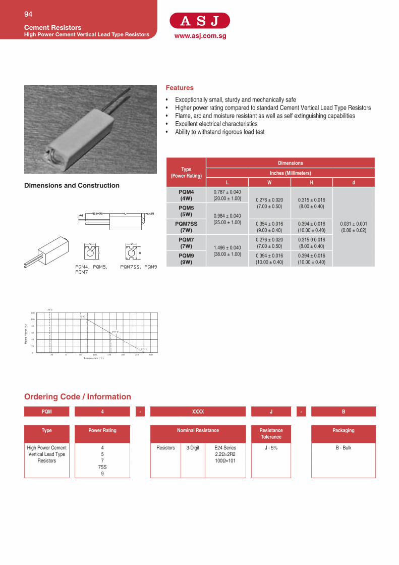
www.asj.com.sg
Features
• Exceptionallysmall,sturdyandmechanicallysafe
• HigherpowerratingcomparedtostandardCementVerticalLeadTypeResistors
• Flame,arcandmoistureresistantaswellasselfextinguishingcapabilities
• Excellentelectricalcharacteristics
• Abilitytowithstandrigorousloadtest
Dimensions and Construction
Ordering Code / Information
Cement ResistorsHigh Power Cement Vertical Lead Type Resistors
94
200 250 30050 100 150-50 0
40
20
0
120
100
80
60
Temperature (˚C )
Rat
ed P
ower
(%)
155˚C
70˚C
-55˚C
275˚C
Type(Power Rating)
Dimensions
Inches (Millimeters)
L W H d
PQM4(4W)
0.787±0.040
(20.00±1.00) 0.276±0.020
(7.00±0.50)
0.315±0.016
(8.00±0.40)
0.031±0.001
(0.80±0.02)
PQM5(5W) 0.984±0.040
(25.00±1.00)PQM7SS(7W)
0.354±0.016
(9.00±0.40)
0.394±0.016
(10.00±0.40)
PQM7(7W) 1.496±0.040
(38.00±1.00)
0.276±0.020
(7.00±0.50)
0.31500.016
(8.00±0.40)
PQM9(9W)
0.394±0.016
(10.00±0.40)
0.394±0.016
(10.00±0.40)
PQM 4 - XXXX J - B
Type Power Rating Nominal Resistance Resistance Tolerance
Packaging
HighPowerCement
VerticalLeadType
Resistors
4
5
7
7SS
9
Resistors 3-Digit E24Series
2.2Ω=2R2
100Ω=101
J-5%
B-Bulk

Specifications given herein may be changed at any time without prior notice. Please confirm technical specifications with factory before use.
www.asj.com.sgCement Resistors
High Power Cement Vertical Lead Type Resistors
95
Product Type Power Rating @ 70°C T.C.R (ppm/°C) Max Resistance Range J(±5%) Operating Temperature Range
PQM4 4W
±400
0.1Ω-2.5KΩ
-55°Cto+155°C
PQM5 5W 0.1Ω-2.7KΩ
PQM7 7W 0.3Ω-3.9KΩ
PQM7SS 7W 0.1Ω-2.7KΩ
PQM9 9W 0.3Ω-3.9KΩ
Test Specification Conditions
Resistance Value Withinresistorsspecification Tobemeasureat25°C
Short Time Overload ±(2.0%+0.05Ω) 2.5timesRCWVfor5seconds
Dielectric Withstanding Voltage Withinresistorsspecification InV-Blockfor60seconds
Temperature Coefficient of Resistance Withinresistorsspecification -55°Cto+155°C
Solderability 95%min.coverage 260°C±5°Cfor5±0.5seconds
Load Life In Humidity ±(5.0%+0.1Ω) 40°C±2°C,90%-95%RHatRCWVfor1000hrs
(1.5hrs.on,0.5hrs.off)
Load Life ±(5.0%+0.1Ω) 70°CatRCWVfor1000hrs
(1.5hrs.on,0.5hrs.off)
Resistance To Soldering Heat ±(1.0%+0.05Ω) 350°C±10°Cfor3±0.5seconds
Application and Ratings

www.asj.com.sg
Features
• Goodheatdissipation
• Excellentelectricalcharacteristics
• Abilitytowithstandrigorousloadtest
• Flame,arcandmoistureresistanceaswellasselfextinguishingcapabilities
Dimensions and Construction
Ordering Code / Information
Cement ResistorsCement Radial Terminals Type Resistors
96
Type(Power Rating)
Dimensions
Millimeters
L P W1 W2 W3 H1 H2 H3
SQZ5(5W)
1.063±
0.040
(27.00±
1.00)
0.591±
0.059
(15.00±
1.50)
0.374±
0.040(9.50
±1.00)
0.287±
0.020(7.30
±0.50)
0.177±
0.020(4.50
±0.50)
0.374±
0.040(9.50
±1.00)
0.374±
0.020(9.50
±0.50)
0.591±
0.020
(15.00±
0.50)
SQZ7(7W)
1.378±
0.040
(35.00±
1.00)
0.787±
0.059
(20.00±
1.50)
SQZ10(10W) 1.890±
0.040
(48.00±
1.00)
1.260±
0.059
(32.00±
1.50)
SQZ15(15W)
0.492±
0.040
(12.50±
1.00)
0.394±
0.020
(10.00±
0.50)
0.197±
0.020(5.00
±0.50)
0.472±
0.040
(12.00±
1.00)
0.591±
0.020
(15.00±
0.50)
0.827±
0.020
(21.00±
0.50)SQZ20(20W)
2.362±
0.040
(60.00±
1.00)
1.654±
0.059
(42.00±
1.50)
0.591±
0.040
(15.00±
1.00)
0.512±
0.040
(13.00±
1.00)
SQZ 5 - XXXX J - B
Type Power Rating Nominal Resistance Resistance Tolerance
Packaging
CementRadial
TerminalsType
Resistors
5
7
10
15
20
Resistors 3-Digit
E24Series
2.2Ω=2R2
100Ω=101
J-5% B=Bulk
25 12550 175 200 225100 150 275
40
20
0-50 0 75 250
120
100
80
60
Temperature (°C)
Rat
ed P
ower
(%)
155°C70°C-55°C 275°C40°C
(5W , 7W , 10W)
25°
(15W , 20W)

Specifications given herein may be changed at any time without prior notice. Please confirm technical specifications with factory before use.
www.asj.com.sgCement Resistors
Cement Radial Terminals Type Resistors
97
Product Type Power Rating @ 70°C T.C.R (ppm/°C) Max Resistance RangeE-24
J(±5%)
Operating Temperature Range
SQZ5 5W
±300 0.1Ω-100KΩ -55°Cto+155°C
SQZ7 7W
SQZ10 10W
SQZ15 15W
SQZ20 20W
Test Specification Conditions
Resistance Value Withinresistorsspecification Tobemeasureat25°C
Short Time Overload ±(2%+0.05Ω) 2.5timesRCWVfor5seconds
Dielectric Withstanding Voltage ±(1.0%+0.05Ω) InV-Blockfor60seconds
Temperature Coefficient of Resistance ±300ppm/°C RoomTemp.±100°C
Solderability 95%min.coverage 235°Cfor5±0.5seconds
Load Life In Humidity ±(5.0%+0.05Ω) 40°C±2°C,90%-95%RHatRCWVfor1000hrs
(1.5hrs.on,0.5hrs.off)
Load Life ±(5.0%+0.05Ω) 70°CatRCWVfor1000hrs
(1.5hrs.on,0.5hrs.off)
Resistance To Soldering Heat ±(1.0%+0.05Ω) 260°C±10°Cfor3±0.5seconds
Application and Ratings

www.asj.com.sg
Features
• Completelyinflammable
• Rectangular,clampmountingtype
Dimensions and Construction
Ordering Code / Information
Cement ResistorsRectangular Cement Clamp Mounting TypeResistors
98
120
-40 -20 200
40
60
80
100
20
020040 60 80 100 120 140 160 180 220 240 260 280
Temperature (˚C )
Rat
ed L
oad
(%)
155˚C
70˚C-55˚C
275˚C
Type (Power Rating)
Dimensions
Inches (Milimeters)
L H W S H1 P1 P2 P3 P4 d T D
SQH(10W)
1.890±
0.060
(48.00
±1.50)
0.413±
0.040
(10.50
±1.00)
0.413±
0.002
(10.50
±1.00)
1.300±
0.079
(33.00
±2.00)
0.768±
0.040
(19.50
±1.00)
0.472±
0.020
(12.0±
0.5)
0.236±
0.020
(6.00±
0.50)
0.315±
0.020
(8.00±
0.50)
0.118±
0.020
(3.00±
0.50)
0.150±
0.020
(3.80±
0.50)
0.217±
0.020
(5.50±
0.50)
0.094±
0.012
(2.40±
0.30)
SQH(15W)
0.492±
0.040
(12.50
±1.00)
0.492±
0.040
(12.50
±1.00)
0.807±
0.040
(20.50
±1.00)
0.244±
0.020
(6.20±
0.50)
SQH(20W)
2.500±
0.079
(63.50
±2.00)
1.890±
0.079
(48.00
±2.00)
0.295±
0.020
(7.50±
0.50)
0.126±
0.012
(3.20±
0.30)
SQH(25W)
0.630±
0.002
(16.00
±1.00)
0.630±
0.040
(16.00
±1.00)
1.811±
0.079
(46.00
±2.00)
1.102±
0.059
(28.00
±1.50)
0.394±
0.020
(10.00
±0.50)
SQH(30W)
2.953±
0.079
(75.00
±2.00)
0.748±
0.002
(19.00
±1.00)
0.748±
0.079
(19.00
±2.00)
2.205±
0.079
(56.00
±2.00)
1.142±
0.059
(29.00
±1.50)
0.709±
0.020
(18.00
±0.50)
0.315±
0.020
(8.00±
0.50)
0.165±
0.020
(4.20±
0.50)
SQH(40W)
3.543±
0.118
(90.00
±3.00)
2.677±
0.079
(68.00
±2.00)
0.354±
0.020
(9.00±
0.50)
SQH 10 - XXXX J - B
Type Power Rating Nominal Resistance Resistance Tolerance
Packaging
Rectangular
CementClamp
MountingType
Resistors
10
15
20
25
30
40
Resistors 3-Digit
E24Series
2.2Ω=2R2
100Ω=101
J-5%
B=Bulk

Specifications given herein may be changed at any time without prior notice. Please confirm technical specifications with factory before use.
www.asj.com.sg
Cement ResistorsRectangular Cement Clamp Mounting Type
Resistors
99
Product Type Power Rating @ 70°C T.C.R (ppm/°C) Max Resistance RangeE-24
J(±5%)
Operating Temperature Range
SQH10 10W
±300 0.1Ω-100KΩ -55°Cto+155°C
SQH15 15W
SQH12 20W
SQH13 25W
SQH14 30W
SQH15 40W
Test Specification Test Method
Resistance Value WithinResistorsspecification Tobemeasureat25°C
Resistance Temperature Coefficient WithinSpecificationofTCR 25°C/+125°C
Short Time Overload ±(2.0%+0.05Ω) For5%toleranceApply2.5timesofratedvoltageormaximumoverloadvoltagefor
5secswhichislower
Resistance to Soldering Heat ±(1.0%+0.05Ω) For5%tolerance 260°C±5°C,10seconds±1second
Moisture Resistance ±(5.0%+0.05Ω) For5%tolerance 40°C±2°C,90%-95%RH,1000hours
Load Life ±(5.0%+0.05Ω) For5%tolerance 70°C±2°C,1000hours,1.5hoursOn,0.5hoursOffcycle
High Temperature Exposure ±(2.0%+0.05Ω) For5%tolerance 275°C±3°C,for2hours
Application and Ratings

www.asj.com.sg
Features
• Excellentflame,arcandmoistureresistanceaswellasselfextinguishing
capabilities
• Abilitytowithstandthemostrigorousloadingtests
Dimensions and Construction
Ordering Code / Information
Cement ResistorsCement Radial Lead Type Resistors
100
Type(Power Rating)
Dimensions
Inches (Millimeters)
A B C D d p
SQL2(2W)
0.315±0.040
(8.00±1.00) 0.512±0.040
(13.00±1.00)
0.138±0.040
(3.50±1.00)
0.197±0.040
(5.00±1.00)
0.024±0.002
(0.60±0.05)
0.354±0.040
(9.00±1.00)
SQL3(3W)
0.512±0.040
(13.00±1.00)
0.315±0.040
(8.00±1.00)
SQL5(5W) 0.709±0.040
(18.00±1.00)
0.551±0.040
(14.00±1.00)
0.394±0.040
(10.00±1.00)
SQL7(7W) 1.024±0.040
(26.00±1.00)
0.031±0.002
(0.80±0.05)
0.787±0.040
(20.00±1.00)SQL10(10W)
0.787±0.040
(20.00±1.00)
SQL 2 - XXX J - B
Type Power Rating Nominal Resistance Resistance Tolerance
Packaging
CementRadial
LeadType
Resistors
2
3
5
7
10
Resistors 3-Digit
E24Series
2.2Ω=2R2
100Ω=101
J-5% B-Bulk
200 250 30050 100 150-50 0
40
20
0
120
100
80
60
Temperature (˚C )
Rat
ed P
ower
(%)
155˚C
70˚C-55˚C
275˚C
40˚C
(2W )
(3W , 5W , 7W , 10W )

Specifications given herein may be changed at any time without prior notice. Please confirm technical specifications with factory before use.
www.asj.com.sgCement Resistors
Cement Radial Lead Type Resistors
101
Product Type Power Rating @ 70°C T.C.R (ppm/°C) Max Resistance RangeE-24
J(±5%)
Max Working Voltage Max Overload Voltage
Operating Temperature Range
SQL2 2W
±250
0.1Ω-0.68Ω 250V 500V
-55°Cto+155°C
SQL3 3W 0.05Ω-1Ω
350V 700V
SQL5 5W
0.05Ω-3.3ΩSQL7 7W
500V 1,000V
SQL10 10W
Test Specification Conditions
Resistance Value Withinresistorsspecification Tobemeasureat25°C
Short Time Overload ±(2%+0.05Ω) 2.5timesRCWVfor5seconds
Dielectric Withstanding Voltage Withinresistorsspecification InV-Blockfor60seconds
Temperature Coefficient of Resistance Withinresistorsspecification -55°Cto+155°C
Solderability 95%min.coverage 260°C±5°Cfor5±0.5seconds
Load Life In Humidity ±(5.0%+0.05Ω) 40°C±2°C,90%-95%RHatRCWVfor1000hrs
(1.5hrs.on,0.5hrs.off)
Load Life ±(5.0%+0.05Ω) 70°CatRCWVfor1000hrs
(1.5hrs.on,0.5hrs.off)
Resistance To Soldering Heat ±(1.0%+0.05Ω) 350°C±10°Cfor3±0.5seconds
Application and Ratings

www.asj.com.sg
Features
• Preventsoverloading
• Provideoutstandingfeatureagainstsurges,suitableforthepreventionofinrush
currentforswitchingregulators
Dimensions and Construction
Ordering Code / Information
Cement ResistorsFusible Thermal Cement Type Resistors
102
Type (Power Rating)
Dimensions
Inches (Millimeters)
H W S P d2
FTR1000.984±0.059
(25.00±1.50) 0.512±0.040
(13.00±1.00)
0.354±0.040
(9.00±1.00)
0.197±0.040
(5.00±1.00)
2A:0.024±0.004
(0.60±0.10)
3A:0.024±0.004
(0.60±0.10)
5A:0.040±0.004
(1.00±0.10)
10A:0.040±0.004
(1.00±0.10)
FTR2001.500±0.059
(38.00±1.50)
FTR3001.378±0.059
(35.00±1.50)
0.551±0.040
(14.00±1.00)
0.472±0.040
(12.0±1.0)
0.295±0.040
(7.50±1.00)
FTR 2A - XXX J - B
Type Current Rating Nominal Resistance Resistance Tolerance
Packaging
FusibleThermal
CementType
Resistors
2A
Resistors 3-Digit
E24Series
2.2Ω=2R2
100Ω=101
J-5% B=Bulk
3A
5A
10A

Specifications given herein may be changed at any time without prior notice. Please confirm technical specifications with factory before use.
www.asj.com.sgCement Resistors
Fusible Thermal Cement Type Resistors
103
Product Type Standard Current Rating
Fusing Temperature
(°C)
T.C.R (ppm/°C) Max
Resistance Range J(±5%)
Standard Voltage
Operating Temperature
Range
FTR 100
FTR 200
FTR 300
Power Rating at 70°C
FTR100 FTR200 FTR300
10A
109+1/-3
±250 1Ω-10KΩ 250V -25°Cto+125°C
1.2 1.4 2.0
129±4 1.6 2.0 2.5
152±-4 1.6 2.0 2.5
188+3/-1 2.0 2.4 3.5
226+1/-3 2.0
5A129±3 1.6 2.2 -
187+1/-3 2.1 2.4 -
3A 145±4 1.6 2.2 -
2A
95+3/0 0.8 1.2 -
110±4 1.2 1.4 -
126±4 1.4 1.6 -
130±4 1.6 2.1 -
145±4 2.1 2.4 -
Test Specification Conditions
Resistance Value Withinresistorsspecification Tobemeasureat25°C
Short Time Overload ±(2.0%+0.05Ω) 2.5timesRCWVfor5seconds
Temperature Coefficient of Resistance Withinresistorsspecification -55°Cto+155°C
Load Life ±(5.0%+0.1Ω) 70°CatRCWVfor1000hrs
(1.5hrs.on,0.5hrs.off)
Application and Ratings

www.asj.com.sg
Features
• InterconnectiondevicesbetweenpointsonaPCB
• Suitableforautomaticmachineinsertion
Dimensions and Construction
Ordering Code / Information
JumperZero Ohm Jumper Leaded Resistors
104
120 14040 60 80 100
4
5
1
0160 180 200-40 -20 200
2
3
T emperature (˚C )
Amps
155˚C
70˚C
-55˚C
(Z25)
(Z16)
Dimensions
Type Inches (Millimeters)
L D d l
Z16(1.6A)
0.130±0.012
(3.30±0.30)
0.067±0.008
(1.70±0.20)
0.018±0.002
(0.45±0.05) 1.102±0.079
(28.00±2.00)Z25(2.5A)
0.248±0.020
(6.30±0.50)
0.091±0.020
(2.30±0.50)
0.024±0.002
(0.60±0.05)
Z 16 - A 5
Type Current Rating Packaging Quantity
ZeroOhmJumper
LeadedResistors
16
25
A=Ammo
S=Spool
B=Bulk
1=1,000pcs
2=2,000pcs
5=5,000pcs

www.asj.com.sgJumper
Zero Ohm Jumper Leaded Resistors
105
Product Type Current Rating (A) Min. Dielectric Withstanding Voltage
Resistance Range Operating Temperature Range
Z16 1.6A 300V
0.02ΩMaximum -55°Cto+155°C
Z25 2.5A 500V
Test Specification Test Method
Resistance Value <0.02Ω Tobemeasureat25°C
Resistance to Soldering Heat <0.02Ω 260°C±5°C,10seconds±1second
Load Life <0.02Ω 70°C±2°C,1000hours,1.5hoursOn,0.5hoursOffcycle
High Temperature Exposure <0.02Ω 125°C,1000hours.Unpowered.Measurementat24±2hoursaftertestconclusion
<0.02Ω
Application and Ratings

www.asj.com.sg
Features
• InterconnectiondevicesbetweenpointsonaPCB
• Suitableforautomaticmachineinsertion
• Lead-freetinnedannealedcopperwire
Dimensions and Construction
Ordering Code / Information
JumperJumper Wires
106
Dimensions
Type Inches (Millimeters)
L d
JW55
2.362±0.040(60.00±1.00)
0.019±0.002(0.48±0.05)
JW56 0.023±0.002(0.58±0.05)
JW57 0.028±0.002(0.70±0.05)
JW58 0.031±0.002(0.80±0.05)
JW60 0.024±0.002(0.60±0.05)
JW 55 - A 10
Type Current Diameter Packaging Quantity
JumperWires 55
56
57
58
60
A=Ammo
10=10,000pcs

www.asj.com.sgJumper
Jumper Wires
107
Test JW55 JW56 JW57 JW58 JW60
Maximum Resistance (Ω) 0.01Ω 0.01Ω 0.01Ω 0.01Ω 0.01Ω
Elongation (%) Min24 Min25 Min25 Min25 Min25
Tensile strength (Kg/mm2) 28 28 28 28 28
Bending strength (cycle) 250g 500g 500g 500g 500g
Min3 Min3 Min3 Min3 Min3
Current rating at 70 0C (AMPS)
6 7.5 8.5 10 7.5
Solderability 260°C,5sec>95%coverage
Appearance SmoothandShinning
Application and Ratings

www.asj.com.sg
Features
• Greatpowerratinginsmallpackagesizeforspaceconstraintboard
• Goodheatdissipation
• StraightleadwireorLug/Threadedtypeavailable
Dimensions and Construction
Ordering Code / Information
SpecialtyAluminum Housed Resistors
108
Dimensions
Type Inches (Millimeters)
L1 L2 L3 A B C ØE S H P
SAT5 / SAL5(5W)
0.984±
0.079
(25.00±
2.00)
0.591±
0.040
(15.00±
1.00)
0.394±
0.040
(10.00±
1.00)
0.650±
0.040
(16.50±
1.00)
0.492±
0.040
(12.50±
1.00)
0.350±
0.040
(8.50±
1.00)
0.079±
0.012
(2.00±
0.30)
0.315±
±0.040
(8.00±
1.00)
0.157±
0.020
(4.00±
0.50)
0.197±
0.079
(5.00±
2.00)
SAT10 / SAL10(10W)
1.260±
0.079
(32.00±
2.00)
0.748±
0.040
(19.00±
1.00)
0.551±
0.040
(14.00±
1.00)
0.787±
0.040
(20.00±
1.00)
0.610±
0.040
(15.50±
1.00)
0.413±
0.040
(10.50±
1.00)
0.394±
0.040
(10.00±
1.00)
0.197±
0.020
(5.00±
0.50)
0.236±
0.079
(6.00±
2.0)
SAT25 / SAL25(25W)
1.850±
0.079
(47.00±
2.00)
1.063±
0.040
(27.00±
1.00)
0.709±
0.040
(18.00±
1.00)
1.063±
0.040
(27.00±
1.00)
0.748±
0.040
(19.00±
1.00)
0.591±
0.040
(15.00±
1.00)
0.126±
0.012
(3.20±
0.30)
0.610±
0.040
(15.50±
1.00)
0.276±
0.020
(7.00±
0.50)
0.394±
0.079
(10.00±
2.0)
SAT50 / SAL50(50W)
2.756±
0.079
(70.00±
2.00)
1.969±
0.040
(50.00±
1.00)
1.535±
0.040
(39.00±
1.00)
1.142±
0.040
(29.00±
1.00)
0.827±
0.040
(21.00±
1.00)
SAT80(80W)
4.016±
0.079
(102.00±
2.00)
2.600±
0.040
(66.00±
1.00)
1.378±
0.040
(35.00±
1.00)
1.850±
0.040
(47.00±
1.00)
1.457±
0.040
(37.00±
1.00)
1.102±
0.040
(28.00±
1.00)
0.177±
0.012
(4.50±
0.30)
0.984±
0.040
(25.00±
1.00)
0.472±
0.020
(12.00±
0.50)
-
SAT100(100W)
5.315±
0.079
(135.00±
2.00)
3.504±
0.040
(89.00±
1.00)
2.717±
0.040
(69.00±
1.00)
2.756±
0.040
(70.00±
1.00)
1.890±
0.040
(48.00±
1.00)
1.811±
0.040
(46.00±
1.00)
0.197±
0.012
(5.00±
0.30)
1.752±
0.040
(44.50±
1.00)
0.768±
0.020
(19.50±
0.50)
SAT250(250W)
6.102±
0.079
(155.00±
2.00)
4.488±
0.040
(114.00±
1.00)
3.858±
0.040
(98.00±
1.00)
3.031±
0.040
(77.00±
1.00)
2.520±
0.040
(64.00±
1.00)
2.087±
0.040
(53.00±
1.00)
2.185±
0.040
(55.50±
1.00)
0.984±
0.020
(25.00±
0.50)
SAT 5 - XXXX C - B
Type Power Rating Nominal Resistance Resistance Tolerance
Packaging
AluminumHousedResistors 5-5W
10-10W
25-25W
50-50W
80-80W
100-100W
250-250W
Resistors
3-Digit
E24Series
2.2Ω=2R2
100Ω=101
C=±0.25%
D=±0.5%
F=±1%
J=±5%
K=±10%
B=Bulk
SAT-LugTerminals
SAL-StraightLeadWire
4-Digit
E96Series
10.2Ω=10R2
10KΩ=1002

www.asj.com.sgSpecialty
Aluminum Housed Resistors
109
Application and Ratings
Product Type PowerRating@70°C T.C.R(ppm/°C)Max ResistanceRange
C(±0.25%),D(±0.5%),F(±1%),
J(±5%),K(±10%)
OperatingTemperatureRange
SAT5 / SAL5 5W
±200
0.1Ω-100Ω
-55°Cto+275°C
SAT10 / SAL10 10W
SAT25 / SAL25 25W
SAT50 / SAL50 50W
SAT80 80W
SAT100 100W
0.1Ω-3KΩ
SAT250 250W
Test Specification Conditions
Resistance Value Withinresistorsspecification Tobemeasureat25°C
Short Time Overload ±(0.5%+0.05Ω) 2.5timesRCWVfor5seconds
Dielectric Withstanding Voltage Withinresistorsspecification InV-Blockfor60seconds
Temperature Coefficient of Resistance Withinresistorsspecification -55°Cto+275°C
Insulation Resistance >100MΩ InV-Block
Solderability 95%min.coverage 260°C±5°Cfor5±0.5seconds
Load Life In Humidity ±(0.5%+0.05Ω) 40°C±2°C,90%-95%RHat1/10xPowerRatingfor1000hrs
(1.5hrs.on,0.5hrs.off)
Load Life ±(1.5%+0.05Ω) 25°CatRCWVfor1000hrs
(1.5hrs.on,0.5hrs.off)
Resistance To Soldering Heat ±(1.0%+0.05Ω) 260°C±10°Cfor3±0.5seconds

www.asj.com.sgPackaging / Taping SpecificationsLeaded Resistors
110
Type
26mmTaping 52mmTaping 73mmTaping 91mmTaping T(max.
deviationof
spacing)a A S a A S a A S a A S
MF 6.0±0.5 26.0±1.0 5.0±1.0 6.0±0.5 52.0±1.0 5.0±1.0 6.0±0.5 73.0±1.5 10.0±1.0 - - -
1mmper10
spacings
0.5mmper
5spacings
CF 6.0±0.5 26.0±1.0 5.0±1.0 6.0±0.5 52.0±1.0 5.0±1.0 6.0±0.5 73.0±1.5 10.0±1.0 - - -
MO 6.0±0.5 26.0±1.0 5.0±1.0 6.0±0.5 52.0±1.0 5.0±1.0 6.0±0.5 73.0±1.5 10.0±1.0 6.2±0.5 91.0±1.010.16±
1.0
KNP - - - 6.0±0.5 52.0±1.0 5.0±1.0 6.0±0.5 73.0±1.5 10.0±1.0 6.0±0.5 91.0±1.0 10.0±1.0
JW - - - 6.0±0.5 52.0±1.0 5.0±1.0 - - - - - -
Z 6.0±0.5 26.0±1.0 5.0±1.0 6.0±0.5 52.0±1.0 5.0±1.0 - - - - - -
FM 6.0±0.5 26.0±1.0 5.0±1.0 6.0±0.5 52.0±1.0 5.0±1.0 6.0±0.5 73.0±1.5 10.0±1.0 - - -
FSR - - - 6.0±0.5 52.4±1.5 5.0±1.0 6.0±0.5 73.0±1.5 10.0±1.0 - - -
FP 6.0±0.5 26.0±1.5 5.0±1.0 6.0±0.5 52.0±1.0 5.0±1.0 6.0±0.5 73.0±1.5 5.0±1.0 - - -
MGH 6.0±0.5 26.0±1.5 5.0±1.0 6.0±0.5 52.4±1.5 5.0±1.0 6.0±0.5 73.0±1.5 10.0±1.0 - - -
MGP 6.0±0.5 26.0±1.5 5.0±1.0 6.0±0.5 52.4±1.5 5.0±1.0 6.0±0.5 73.0±1.5 10.0±1.0 - - -
KNH - - - 6.0±0.5 52.4±1.5 5.0±1.0 6.0±0.5 73.0±1.5 10.0±1.0 - - -
FWW - - - 6.0±0.5 52.4±1.5 5.0±1.0 6.0±0.5 73.0±1.5 10.0±1.0 6.0±0.5 91.0±1.0 10.0±1.0
Dimensions(Millimeters)
Dimensions and Construction
Dimensions and Construction
Type Quantity Per Reel (Pcs)
Across Flange (A)
Normal Small Size 26mm Tapping 52mm Tapping 73 mm Tapping
MF50 MF55SS 5000
-
72
-
MF55 MF60SS 5000 72
MF60 - 1000/3000 72 95
MF70 - 1000/2000
-
95
MF75 - 1000 95
Dimensions(Millimeters)

www.asj.com.sgPackaging / Taping Specifications
Leaded Resistors
111
Type Quantity Per Reel (Pcs)
Across Flange (A)
Normal Small Size 26mm Tapping 52mm Tapping 73 mm Tapping
CF1/6 CF1/4SS
5000
-
72
-
CF1/4 CF1/2SS 72
CF1/2 CF1SS 3000 72
CF1 CF2SS 1000/3000 72
CF2 - 1000/2000
-
95
CF3 - 1000 95
MO1/4 MO1/2SS 5000
-
72
-
MO1/2 MO1SS 3000 72
MO1 MO2SS 2000 72 95
MO2 MO3SS
1000
-
95
MO3 - 95
MO5 MO5SS 500 95
KNP1/4 KNP1/2SS 5000
-
72
-
KNP1/2 KNP1SS 3000 72
KNP1 KNP2SS 2000 72 95
KNP2 KNP3SS
1000
72 95
KNP3 - - 95
Z16 / Z25 - 5000 40 75 -
FM50 FM55SS 5000 48 72
-FM55 FM60SS 5000 48 72
FM60 - 3000
-
72
FM65 - 2000
-
95
FM70 - 1000 95
FP1/6 FP1/4SS 5000 48 72
-FP1/4 FP1/2SS 5000 48 72
FP1/2 - 3000
-
72
FP1 - 1000
-
95
FP2 - 1000 95
MGH1/4 - 5000 48 72
-MGH1/2 - 2500
-
72
- MGH1SS 2500 72
MGH1 - 1000 - 95
MGP1/4 5000 48 72
-- MGP1/2SS 5000 48 72
MGP1/2 - 2500
-
72
MGP1 - 2000
-
95
MGP2 - 1000 95
KNH1 - 5,000
-
72
-
KNH2 - 2,500 72
KNH3 - 2,000
- -
95
KNH4 - 1,000 95

www.asj.com.sgPackaging / Taping SpecificationsLeaded Resistors
112
Dimensions and Construction
TypeNO.OF
UNITS26MMTAPING 52MMTAPING 73MMTAPING 91MMTAPING
NormalSmall
SizeL W H L W H L W H L W H
KNH2 - 2,500 - - - 260 81 104 - - - - - -
KNH3 - 2,000 - - - - - - 260 103 78
KNH4 - 1,000 - - - - - - 260 103 94
Dimensions(Millimeters)
TypePcs /Per Bag Pcs /Per Box
Normal Small Size
KNP6 , KNP7 , KNP8 , KNP10 - 50 200
JW55 , JW56 , JW57 , JW58 , JW60 - - 10,000
SQP2 , SQP3 , SQP5 - 50 500
SQP7 , SQP10 , SQP15
- 50 200
SQP20 , SQP25 - 25 100
SQM2 , SQM3 , SQM5 - 50 500
SQM7 - 50 400
SQM10 SQM10SS , SQM15SS 50 200
SQZ5 , SQZ7 , SQZ10 - 50 200
SQZ15 , SQZ20 - 25 100
SQH10 , SQH15 , SQH12 - - 30
SQH13 , SQH14 , SQH15 - - 20
*Forotherproducts,packagingquantityvarieswithorderquantity.Pleaseconsultfactory.
Dimensions(Millimeters)

www.asj.com.sg
NOMINAL STANDARD RESISTANCE VALUES FOR THE 10-TO-100 DECADE(alsousableindecademultiplesorsub-multiples)
Resistance Tolerance (±%)0.1% 1% 0.1% 1% 0.1% 1% 0.1% 1% 0.1% 1% 0.1% 1%
0.25% 1% 2% 0.25% 1% 2% 0.25% 1% 2% 0.25% 1% 2% 0.25% 1% 2% 0.25% 1% 2%
0.5% 5% 0.5% 5% 0.5% 5% 0.5% 5% 0.5% 5% 0.5% 5%
10.0 10.0 10 14.7 14.7 - 21.5 21.5 - 31.6 31.6 - 46.4 46.4 - 68.1 68.1 68
10.1 - - 14.9 - - 21.8 - - 32.0 - - 47.0 - 47 69.0 - -
10.2 10.2 - 15.0 15.0 15 22.1 22.1 22 32.4 32.4 - 47.5 47.5 - 69.8 69.8 -
10.4 - - 15.2 - - 22.3 - - 32.8 - - 48.1 - - 70.6 - -
10.5 10.5 - 15.4 15.4 - 22.6 22.6 - 33.2 33.2 33 48.7 48.7 - 71.5 71.5 -
10.6 - - 15.6 - - 22.9 - - 33.6 - - 49.3 - - 72.3 - -
10.7 10.7 - 15.8 15.8 - 23.2 23.2 - 34.0 34.0 - 49.9 49.9 - 73.2 73.2 -
10.9 - - 16.0 - 16 23.4 - - 34.4 - - 50.5 - - 74.1 - -
11.0 11.0 11 16.2 16.2 - 23.7 23.7 - 34.8 34.8 - 51.1 51.1 51 75.0 75.0 75
11.1 - - 16.4 - - 24.0 - 24 35.2 - - 51.7 - - 75.9 - -
11.3 11.3 - 16.5 16.5 - 24.3 24.3 - 35.7 35.7 - 52.3 52.3 - 76.8 76.8 -
11.4 - - 16.7 - - 24.6 - - 36.1 - 36 53.0 - - 77.7 - -
11.5 11.5 - 16.9 16.9 - 24.9 24.9 - 36.5 36.5 - 53.6 53.6 - 78.7 78.7 -
11.7 - - 17.2 - - 25.2 - - 37.0 - - 54.2 - - 79.6 - -
11.8 11.8 - 17.4 17.4 - 25.5 25.5 - 37.4 37.4 - 54.9 54.9 - 80.6 80.6 -
12.0 - 12 17.6 - - 25.8 - - 37.9 - - 55.6 - - 81.6 - -
12.1 12.1 - 17.8 17.8 - 26.1 26.1 - 38.3 38.3 - 56.2 56.2 56 82.5 82.5 82
12.3 - - 18.0 - 18 26.4 - - 38.8 - - 56.9 - - 83.5 - -
12.4 12.4 - 18.2 18.2 - 26.7 26.7 - 39.2 39.2 39 57.6 57.6 - 84.5 84.5 -
12.6 - - 18.4 - - 27.1 - 27 39.7 - - 58.3 - - 85.6 - -
12.7 12.7 - 18.7 18.7 - 27.4 27.4 - 40.2 40.2 - 59.0 59.0 - 86.6 86.6 -
12.9 - - 18.9 - - 27.7 - - 40.7 - - 59.7 - - 87.6 - -
13.0 13.0 13 19.1 19.1 - 28.0 28.0 - 41.2 41.2 - 60.4 60.4 - 88.7 88.7 -
13.2 - - 19.3 - - 28.4 - - 41.7 - - 61.2 - - 89.8 - -
13.3 13.3 - 19.6 19.6 - 28.7 28.7 - 42.2 42.2 - 61.9 61.9 62 90.9 90.9 91
13.5 - - 19.8 - - 29.1 - - 42.7 - - 62.6 - - 92.0 - -
13.7 13.7 - 20.0 20.0 20 29.4 29.4 - 43.2 43.2 43 63.4 63.4 - 93.1 93.1 -
13.8 - - 20.3 - - 29.8 - - 43.7 - - 64.2 - - 94.2 - -
14.0 14.0 - 20.5 20.5 - 30.1 30.1 30 44.2 44.2 - 64.9 64.9 - 95.3 95.3 -
14.2 - - 20.8 - - 30.5 - - 44.8 - - 65.7 - - 96.5 - -
14.3 14.3 - 21.0 21.0 - 30.9 30.9 - 45.3 45.3 - 66.5 66.5 - 97.6 97.6 -
14.5 - - 21.3 - - 31.2 - - 45.9 - - 67.3 - - 98.8 - -
E-192 E-96 E-24 E-192 E-96 E-24 E-192 E-96 E-24 E-192 E-96 E-24 E-192 E-96 E-24 E-192 E-96 E-24
Note: Specificationorreferenceinthepublicationareonlygivenforinformation,withoutanyguaranteeasregardstoeithermistakesoromissions.Informationfurnishedis
believedtobeaccurateandreliableattimeofprinting.However,ASJPTELTDassumesnoresponsibilityfortheconsequencesofuseofsuchinformationnorforany
infringementofpatentsorotherrightsofpartieswhichmayresultfromitsuse.Specificationsmentionedinthispublicationaresubjecttochangeswithoutnotice.This
publicationsupersedesandreplacesallinformationpreviouslypublished.ProductsfromASJPTELTDarenotauthorizedforuseascriticalcomponentsinlifesupport
devicesorsystemswithoutwrittenapproval.
Nominal Standard Resistance Values
113

www.asj.com.sgManufacturing, Sales & Distribution Network
114
MANUFACTURING PLANT
MALAYSIA
ASJ COMPONENTS (M) SDN BHD PTD 37440 Jalan Perindustrian Senai 3
Kawasan Perindustrian Senai Fasa 2
81400 Senai, Johor, Malaysia
Tel : (607) 597 7800
Fax : (607) 598 7946
Email : [email protected]
CHINA
ASJ (HONG KONG) LIMITED Unit Nos. 323 to 327
3rd Floor, Hi-Tech Centre
No.9 Choi Yuen Road
Sheung Shui, N.T., Hong Kong
Tel : (852) 2672 6363
Fax : (852) 2672 2002
Email : [email protected]
ASJ COMPONENTS (SHENZHEN) CO. LTDRm 608, A block, Galaxy Century Building
No. 3069 Cai Tian Road, Fu Tian District
Shen Zhen, 518026 P.R.C
Tel : (86) 755 8280 5872
Fax : (86) 755 8280 5871
Email : [email protected]
U.S.A
ASJ COMPONENTS INC.683 N. Sierra Ave
Nogales, AZ 85621
Tel : (1) 520 287 4731
Fax : (1) 520 287 2109
Email : [email protected]
EURoPE
RUTRONIK ELEKTRONISCHE BAUELEMENTE GMBHIndustriestraBe 2
75228 Ispringen
Germany
Tel : (49) 0 7231 8010
Fax : (49) 0 7231 82282
Web : www.rutronik.com
ASJ COMPONENTS (M) SDN BHD No. 231 & 232, Jalan Murni 10
Taman Perindustrian Murni,
81400 Senai, Johor, Malaysia
Tel : (607) 598 6550
Fax : (607) 598 5808
Email : [email protected]
SALES oFFICES
SINGAPoRE – HEADQUARTERS
ASJ PTE LTD514 Chai Chee Lane #05-05/06
Bedok Industrial Estate
Singapore 469029
Tel : (65) 6412 0800
Fax : (65) 6412 0808
Email : [email protected]
Web : www.asj.com.sg
MALAYSIA
ASJ COMPONENTS (M) SDN BHD PTD 37440 Jalan Perindustrian Senai 3
Kawasan Perindustrian Senai Fasa 2
81400 Senai, Johor, Malaysia
Tel : (607) 597 7800
Fax : (607) 598 7946
Email : [email protected]
ASJ MALAYSIA16A (1
st Floor), Jalan Todak 3
PusatBandar Seberang Jaya
13700 Prai, Pulau Pinang,
Penang Malaysia
Tel : (604) 380 9890
Fax : (604) 397 3137
Email : [email protected]