hardening and tempering steel
DESCRIPTION
Handbook of hardening tempering steel and it usesTRANSCRIPT

LIBRARYOF THE
UNIVERSITY OF CALIFORNIA.
Class
GENERM-


Hardening, Tempering, flnneaiingAND
FORGING OF STEEL
A TREATISE ON THE PRACTICAL TREATMENT ANDWORKING OF HIGH AND LOW GRADE STEEL
COMPRISINGTHE SELECTION AND IDENTIFICATION OF STEEL, THE MOSTMODERN AND APPROVED HEATING, HARDENING, TEMPER-
ING, ANNEALING AND FORGING PROCESSES, THE USEOF GAS BLAST FORGES, HEATING MACHINES ANDFURNACES, THE ANNEALING AND MANUFACTURINGOF MALLEABLE IRON, THE TREATMENT AND USEOF SELF-HARDENING STEEL, WITH SPECIAL
REFERENCE TO CASEHARDENING PROCESSES,THE HARDENING AND TEMPERING OF MILL-
ING CUTTERS AND PRESS TOOLS, THE USEOF MACHINERY STEEL FOR CUTTING
TOOLS, FORGING AND WELDING, HIGHGRADE STEEL FORCINGS IN AMERICA,FORGING OF HOLLOW SHAFTS,
DROP-FORGING, AND GRIND-
ING PROCESSES FOR TOOLSAND MACHINE PARTS
JOSEPH V. WOODWORTHAuthor of "Dies, Their Construction and Use
Illustrated by 201 Engravings
NORMAN W. HENLEY & CO.
132 NASSAU STREETNEW YORK
1903
COPYRIGHTED, 1902,
BYNORMAN W. HENLEY & Co.
MACGOWAN & SLIPPERPRINTERS
30 Beekman StreetNew YorkU.S.A.

TO
GEORGE WOODWORTHMY FATHER, FRIEND AND FEI<I,OW WORKER, TO WHOSE I<OVE,
AFFECTION AND ENCOURAGEMENT I OWE MORE THANCAN EVER BE REPAID, THIS BOOK IS
AFFECTIONATELY DEDICATED
103848


PREFACE.
In preparing this treatise the author has had as an incitement
the knowledge that there was very little information to be had on
the treatment and working of steel of practical value to the gen-eral mechanic. For this reason he is convinced that a practical
book on the treatment and working of the metal as modern de-
mands necessitate, that is, in regard to heating, annealing, forg-
ing, hardening and tempering processes, cannot fail to> prove of
interest and value to all mechanics who use tools or who are in
any way engaged in the working of metals.
When the fact is considered that tools made from the best
grades of steel will not perform the work required unless theyhave been treated properly during the various heating processes,
the value of a knowledge of the most satisfactory and approved
arrangements and methods to the mechanic is at once apparent.
With the object in view of giving to practical men a book
treating and presenting this paramount subject in a clear, con-
cise and practical manner, the author has drawn upon a personal
experience of many years, gathered all the information obtain-
able, eliminating all unnecessary and obsolete matter, and added
all that is approved, up-to-date and authentic.
In regard to originality we lay claim to very little, for, al-
though the facts contained in a large number of the items have
been gained through years of experience at the forge, bench and
machine, we are indebted to others for a greater portion, and
merely claim to have, as a great poet has said, "gathered the
fruits of other men's labors and bound them with our own string.''
To the technical journals, notably the American Machinist, Ma-
chinery, the Iron Age, the Scientific American, the Age of Steel,
Modern Machinery, and Shop Talk; to master mechanics of
well-known shops, to many American machine-tool and tool and
die making concerns, and to individual fellow craftsmen, the
author takes pleasure in herein acknowledging his indebtedness,
with thanks for a laree number of facts contained in this volume.
The chapters on Miscellaneous Methods, Tables, and on Emery
6 PREFACE.
Wheel Grinding of tools, have been thought so near akin to the
general subject of this work, that they have been given a place and
will be found valuable to the tool maker and general machinist.
Much valuable information was furnished, and many of the
engravings which were used to illustrate the work were kindly
loaned to the author by the following named firms : Cincinnati
Milling Machine Company, Cincinnati, Ohio; American Gas Fur-
nace Company, New York, N. Y.;Faneuil Watch Tool Com-
pany, Brighton, Boston, Mass.;Standard Tool Company, Cleve-
land, Ohio; J. H. Williams Company, Brooklyn, N. Y.;
the
Rogers & Hubbard Company, Middletown, Conn. ;Pratt &
Whitney, Hartford, Conn.;
Garvin Machine Company, NewYork, N. Y.
; Armstrong Brothers Tool Company, Chicago, 111.;
Chicago Flexible Shaft Company, Chicago, 111.; Nicholson File
Company, Providence, R. I.; E. W. Bliss Company, Brooklyn,
N. Y.
Although the writer is aware that his efforts will meet with
criticism from those who may feel that it is not technical enough,
or that some particular process or special method has been ig-
nored, he is pleased to assure the reader that all that it does con-
tain has been authenticated, and he is convinced that the
majority will find in its pages information which will assist them
in overcoming trials and difficulties met with in the working of
this "truly wondrous metal."
Brooklyn, N. Y., December, 1902.
JOSEPH V. WOODWORTH.

CONTENTS.
CHAPTER I.
STEEL ITS SELECTION AND IDENTIFICATION STEEL FOR VARIOUS PURPOSES-
THE TREATMENT OF WELL-KNOWN BRANDS OF STEEL
THE EFFECTS OF HEAT.
Selection and Identification of Steel Steel for Different PurposesDie Steel Steel Die Forgings The Treatment of High-Car-
bon Steels Experimental Treatment The Treatment and
Working of Well-known Brands of Tool Steel Heating for
Forging Heating for Hardening Treatment of High-speed
Self-hardening Steels Annealed Die and Tool Steel Treat-
ment of Annealed. Die and Tool Steel Treatment of Air-hard-
ening Steel The Best Steel for Tools Testing Tool Steel
The Grain of Steel Testing for Toughness Economy in -Test-
ing Steel Before Using Decarbonized Steel Surfaces How to
Know Tool Steel from Mild Steel Tool Holders and Tools
Self-hardening Steel Cutting Tools Speeds for Cutting Tools
Cutting and Durability Qualities of Steel Judgment, Experi-
ence, and Perception in the Working of Steel The First Effects
of Heat Unequal Expansion Heat Effects on ClayThe Amount of Force Exerted in Expansion or Contraction
The Second Effect of Heat Table of Expansion from 32 Deg.F. to 212 Deg. F. Kinds of Steel Produced in America bythe Crucible and Open-hearth Processes. 13 to 35
CHAPTER II.
ANNEALING PROCESSES THE TERMS ANNEALING, HARDENING, AND TEMPER-
ING DEFINED THE ANNEALING OF MALLEABLE CASTINGS.
The Terms Defined How to Thoroughly Anneal High-grade Tool
Steel Parts The Proper Heat for Annealing Annealing in
the Charcoal Fire Good Steel for Good Tools AnnealingAn Annealing Box for Small Parts Water Annealing TheEffect of the Water Anneal The Annealing of Tap Steel
Reannealing Tap Blanks How to Heat for Annealing An-
nealing a Small Quantity of Steel Annealing Steel in the
Open Fire Quick Methods for Softening Steel To Anneal
Doubtful Steel Annealing Chilled Cast-iron Dies for Drilling
Annealing White or Silver Iron The Annealing of Malle-

CONTENTS.
able Castings and the Manufacture of Malleable-iron Machine
Parts The Foundry, and Preparation of the Castings An-
nealing Furnaces Packing the Castings Different Methods
of Packing Castings in Pots Annealing, Straightening and
Finishing Malleable Castings Heating the Annealing O'vens
General Matter Relative to Malleable-iron Manufacturing. .. .36 to 49
CHAPTER III.
THE HEATING AND COOLING OF STEEL LOCATION OF HEATING ARRANGE-
MENTS THE USE OF GAS BLAST FURNACES AND HEATING MACHINES
TOUGH STEEL AND HARD STEEL THE DIFFERENCE.
The Heating and Cooling of Steel Proper Equipment for Harden-
ing and Tempering Points to be Remembered The Loca-
tion of the Heating Furnace The Use of Gas-blast Furnaces
and Heating Machines Gas-blast Forges Their Use Combi-
nation Gas Furnace for General Machine-shop Work Gas
Forge for Small Work Gas Forge for Heating Drop Forgings
Air-tempering Furnace Gas Forge for Knife and Shear
Blades Bench Forge Oven Furnaces for Annealing and
Hardening Case-hardening Furnaces Heating-machine for
Hardening the Edges of Mower Blades Heating-machine for
Hardening Cones and Shells Heating-machine with Revolving
Trays Heating-machine for Small Parts Barrel Heating-ma-chine for Hardening and Tempering Balls, Saw Teeth, Screws,
etc Construction and Operation of Barrel Heating-machine
Heating-machine for Tempering and Coloring Steel Circular
Annealing and Hardening Furnace Oil Tempering Furnaces
Automatic Heating-machine for Hardening Chain Cylindri-
cal Case-hardening Furnaces Lead Hardening Furnace
Melting Pots Cyanide Hardening Furnaces Regular Sizes of
Muffles Muffle Furnaces Tough Steel and Hard Steel the
Difference 50 to 94
CHAPTER IV.
THE HARDENING OF STEEL HARDENING IN WATER, BRINE, OIL, AND SOLU-
TIONS SPECIAL PROCESSES FOR SPECIAL STEEL.
Judgment and Carefulness in Hardening Successful HardeningDifferent Quenching Baths Their Effect on Steel General
Directions and Rules for the Hardening of Steel Distortion
Through Uneven Heating The Hardening Fire and the Heat
Quenching for Hardening The Hardening of Long Slender
Tools Hardening Small Parts and Long Thin Parts Harden-
ing in Solutions Heating in Hot Lead for Hardening Hard-
ening Metal Saws Mixture to Prevent Lead from Sticking

CONTENTS. 9
when Heating for Hardening Hardening Long Taper Ream-ers The Use of Clay in Hardening Special Instructions for
Hardening and Tempering Hardening and Tempering Round-thread Dies Hardening Bushings, Shell Reamers, Hobs, etc.
Hardening and Tempering Collet Spring Chucks The Taylor-White Process for Treating Steel 95 to 116
CHAPTER V.
TEMPERING BY COLORS IN OIL ON HOT PLATES BY THERMOMETER IN HOT
WATER IN THE SAND BATH BY SPECIAL METHODS.
Tempering Tempering in the Sand Bath The Effects of Slow
Heating and Tempering Tempering in Oil Hardening and
Tempering Springs Blazing off Springs Tempering RockDrills in Crude Oil Hardening and Tempering Mill
Picks Straightening Hardened Pieces that have WarpedTempering Thin Articles Tempering in the Charcoal
Flame Tempering Wood-planer Knives Tempering Swordsand Cutlasses Drawing Polished Steel Articles to a
Straw Color or Blue Tempering Solutions Table of Melt-
ing Points of Solids Table of Tempers to Which Toolsshould be Drawn Table of Suitable Temperatures for An-
nealing, Working and Hardening Table of Suitable Tem-peratures for Case-hardening, Core Ovens, Drying Kilns, Bak-
ing Enamels and Vulcanizing Rubber Table of Temper Colorsof Steel 117 to 128
CHAPTER VI.
CASE-HARDENING PROCESSES THE USE OF MACHINERY STEEL FOR CUTTING
TOOLS AND THE TREATMENT OF IT.
The Use of Machine Steel for Press Tools Outfit for Fine-
Grain Case-hardening Packing and Heating the Work Case-
hardening Cutting Tools How to Case-harden, Color and An-neal with Granulated Raw Bone To Case-harden WithoutColors Hardening Extra-heavy Work Hardening DrawbridgeDisc and Similar Work Hardening Five-inch Thrust Bearing
Rings How to Harden Rolls, Leaving Tenons Soft for Rivet-
ing How to Case-harden Malleable Iron How to Use Old
Bone Bone and Charcoal Using the Tell-tale Obtaining Col-
ors with Granulated Raw Bone Preparation of the Work
Charring the Bone Packing the Work Heating The Bath
How to Dump the Work Cleaning the Work Colors from a
Light Straw to a Deep Blue Directions for Annealing with
Granulated Raw Bone Cooling Annealing Low-carbon Steel
Bars Annealing Iron Castings Case-hardening with Cyanideof Potassium Accurate Sectional Case-hardening To Produce

IO CONTENTS.
Fine-grained Hardened Machine-steel Parts Case-hardeningthe Ends of Steel Rails Very Deep Case-hardening To Case-
harden Small Iron Parts To Case-harden with Charcoal
Moxon's Method of Case-hardening A Case-hardening Mixturefor Iron A Case-hardening Paste Case-hardening Polished
Parts Case-hardening as it should be Understood 129 to 142
CHAPTER VII.
HARDENING AND TEMPERING MILLING CUTTERS AND SIMILAR TOOLS.
Hardening Milling Cutters in the Open Fire Hardening Large
Milling Cutters Hardening and Tempering Milling Cutters in
Water and Oil Advantages of the Method Hardening V-
shaped Milling Cutters Hardening Hollow Mills Milling
Cutters 143 to 155
CHAPTER VIII.
HARDENING, TEMPERING AND STRAIGHTENING ALL KINDS OF SMALL TOOLS.
Hardening Ring Gages Dipping Small Tools when Hardening
Dipping Half-round Reamers or "Gun" Reamers when Hard-
ening Dipping Fluted Reamers when Hardening Straighten-
ing Long Tools which have Warped in Hardening Hardening
Very Thin Tools so as to Prevent Warping Warping of
Long Tools in Hardening Temperature Tell-tales for Use
in Heating Steel Working Steel for Tools Hardening Small
Saws Hardening Cutter-bits Hardening Mixture for General
Smith Work Tempering Flat Drills for Hard Stock To Tem-
per Gravers To Temper Old Files. Hardening and TemperingSmall Taps, Knives, Springs, etc. Tempering Small Spiral
Springs To Draw Small Steel Parts to a Blue 156 to 161
CHAPTER IX.
THE HARDENING AND TEMPERING OF DIES AND ALL KINDS OF PRESS TOOLS FOR
THE WORKING OF SHEET METAL.
The Hardening and Tempering of Press Tools Hard or Soft
Punches and Dies Hardening and Tempering Drop Dies
How to Harden Large Ring Dies How to Harden a LongPunch so as to Prevent Warping Steel for Small Punches
Hardening a Blanking Die Cracks in Dies Their Cause
Hardening the Walls of a Round Die Reannealing a
Punch, or a Die Blank Warping of Long Punches in
Hardening Hardening Very Small Punches Tempering
Small Punches Hardening Fluids for Dies Hardening Thick

CONTENTS. II
Round Dies Hardening Poor Die Steel Tempering a Combi-
nation Cutting and Drawing Punch Hardening and Temperinga Split Gang Punch Hardening and Tempering Large "Cut-
ting" or "Blanking" Dies 162 to 174
CHAPTER X.
FORGING AND WELDING HOW TO ACCOMPLISH SATISFACTORY RESULTS IN
T::E FORGING AND WELDING OF STEEL AND IRON DROP FORGING.
Welding Heats A Good Welding Flux for Steel Heating Steel
for Forging Steel for Tools which Require to be Forged
High-grade Steel Forgings in America How Hollow Shafts
are Forged Difficulties Encountered in Introducing High-
grade Forgings Cold Crystallization does not Occur Tests
of Steel under Repeated Stresses Charcoal Welding Powderfor Iron and Steel To Make Edged Tools from Cast Steel and
Iron To Weld Cast Iron Welding Composition for Cast Steel
How to Restore Overheated Steel Composition to ToughenSteel Pointer To Weld Buggy Springs A French WeldingFlux Compound for Welding Steel Fluxes for Soldering and
Welding Substitute for Borax in Welding Drop-forgingDirections for Setting up Forging Drop-Hammers Government
Use of Nickel Steel for Forgings 175 to 194
CHAPTER XI.
MISCELLANEOUS METHODS, PROCESSES, KINKS, POINTERS AND TABLES FOR
USE IN METAL WORKING.
Increasing the Size of a Reamer when Worn To Case-harden
Cast Iron Improved Soldering and Tinning Acid Rules for
Calculating Speed Lubricant for Water Cuts Babbitting Lay-
ing out Work Lubricant for Working Aluminum To Prevent
Rust Lubricant for Drilling Hard Steel Coppering Polished
Steel Surfaces To Blue Steel Without Heating To Remove
Scale from Steel To Distinguish Wrought Iron and Cast
Iron from Steel Anti-friction Alloy for Journal Boxes Solder
for Aluminum Case-hardening with Kerosene Case-harden-
ing Cups and Cones Drills Reamer Practice Reamers and
Reaming Number of Teeth Generally Milled in Reamers
Grinding Twist Drills Circular Forming Tools Plain Form-
ing Tools Facing Counterboring Soldering Lacquer for
Brass Articles Removing Rust from Polished Steel and Iron
Miscellaneous Information Useful Information Table of
Decimal Equivalents of Millimeters and Fractions of Milli-
meters Table of Decimal Equivalents of Parts of an Inch
Table of Constants for Finding Diameter at Bottom of Thread

12 CONTENTS.
Table of English or American (U. S.) Equivalent Meas-
ures Table of Weights and Areas of Round, Square and
Hexagon Steel Table of Weights of Iron and Steel Sheets
Table of Weights of Square and Round Bars of WroughtIron in Pounds per Lineal Foot United States Weights and
Measures Table of Tap Drills for Machine Screw TapsTable of Size of Drills for Standard Pipe Taps Table of
Different Standards for Wire Gage used in U. S. Table of
United States Standard Screw Threads Formulas for Sharp
V Thread, United States Standard Thread, Whitworth
Standard Thread The Acme Standard Thread Table of
Thread Parts Table of Average Cutting Speeds for Drills
Table of Cutting Speeds Horse Power of Belts Cutting
Lubricant 195 to 225
CHAPTER XII.
GRINDING THE ACCURATE AND RAPID GRINDING OF TOOLS AND SMALL
MACHINE PARTS EMERY WHEELS THEIR USE.
Cutter and Tool Grinding Prominent Features Grinding a Spiral
Mill Grinding Angular Cutters Grinding Side-milling Cut-
ters Grinding Milling Cutters or Metal Slitting Saws from 8
to 12 Inches in Diameter Gear Cutter Grinding Grinding
Formed Cutters How to Grind a Worm-wheel Hob Grinding
a Hand Reamer Grinding a Taper Reamer How to Grind a
Hardened Drilling Jig Bushing How to Grind a Taper Spindle
How to Grind a Slitting Knife with Beveled Edges Internal
Grinding Grinding a Straight Edge Grinding a Shear Plate
How to Grind a Die Blank' to the Required Angle Grinding
a Formed Tool on its Face The Emery Wheel Used as a
Metal Slitting Saw Grinding a Gage to a Given Dimension-
Attachment for Surface Grinding How to Grind Milling Cut-
ters and Metal 'Slitting Saws Straight or Concave General
Directions Diamond Tool Holder A Small Cutter Grinder-
Illustration Showing Various Work Performed on a Different
Type of Universal Cutter and Tool Grinder Attachments
which are Used on the Machine Emery Wheels Their Use-
Approximate Speeds for Emery and Polishing Wheels Table
of Articles Made from Crucible Steel, Giving About Percent-
age of Carbon they should Contain 226 to 275
CHAPTER I.
STEEL, ITS SELECTION AND IDENTIFICATION STEEL FOR VARIOUS
PURPOSES THE TREATMENT AND WORKING OF WELL-KNOWN
BRANDS OF TOOL STEEL THE EFFECTS OF HEAT.
Selection and Identification of Steel.
It would be a fine thing if we could start with giving the
name of a brand of tool steel which would answer for all kinds
of tools; would harden without trouble, and temper evenly in the
"good old-fashioned way." But as we cannot do this, we can
only hope that some day a steel which will answer for all purposes
will be produced ;until then we must rest content with what
we have got and through experience learn of the best brand of
steel to use for a given purpose.
There is absolutely no economy in- purchasing tool steel be-
cause it is cheap. In fact, economy in steel can only be obtained
by purchasing a grade of steel which is uniformly of the best
quality, as its superior lasting quality, and its ability to retain a
cutting edge for long periods make it the cheapest and most
satisfactory in the end. Such steel costs more in the beginning,
but then cheap steel has often cost almost "its weight in gold"
before it was thrown out. Almost every machinist, who has
worked in any number of shops, has had experience with the
different grades and brands of steel for tools, and he knows that
cheap steel is expensive.
As the first thing necessary to allow of successful metal work-
ing, in any branch of the machinist's art is good steel, too muchattention cannot be given to the selection of a steel of uniform
quality. This can only be brought about through experience in
working and using the different brands for purposes required,
and when a grade has been procured which can be handled suc-
cessfully and gives satisfaction in use, stick to it and never
change until you are convinced that you have struck a better one.
After having selected the brands and grades of steel that are
suited for the classes of work required, adopt some method of
marking each separate brand so the workmen will be able to
recognize them without the fire and water test. The best wayto insure against difficulty arising from the mistakes in usingthe wrong brand of steel is to have each brand or grade striped

14 HARDENING, TEMPERING AND ANNEALING.
with a different color paint. Have some one stripe the steels
along" their entire length, as soon as received, and either place each
brand in a separate rack with the name of the steel on it, or have
a board hanging near the steel rack with short stripes of paint of
the colors used and the name of each brand next the stripe de-
noting it. In this manner the brand of steel desired can be found
in a moment with the certainty that it will be the right brand.
Steel for Different Purposes.
For small reamers, taps, small round punches, which are to
cut at slow speeds, and other tools of a like nature, use drill rod,
not necessarily Stubs any good American drill rod will answer
as well. Never use a very high carbon steel for taps and dies or
other threading tools.
Die Steel.
In no branch of the machinist's art should more attention be
given to the importance of the proper selection of steel than in
die-making, as the working qualities of the tools when finished
and their efficiency depend upon this more than anything else.
When ordering steel which is to be used for dies be sure to
specify that annealed steel is wanted, as the saving of time and
labor in the working of it, and the certainty of the results in the
hardening and tempering of it after the re-annealing, will be a
source of gratification to the mechanic. When these results
are considered the slight extra cost of annealed steel is insig-
nificant.
As to the grade of steel to use for dies, be sure to get a good
grade, and as there are several brands of steel on the market
which are used principally for dies and punches no difficulty
should be experienced in procuring a grade or brand which will
prove suitable for any special class of sheet-metal work.
Steel Die Forgings.
When steel forgings are required, from which dies are to
be made, the job should be given to a smith who understands
this branch of his art, as in order for the forgings to machine
well and allow of being hardened and tempered as desired, so
that the finished tools will accomplish the required results, the
smith must understand such work. As too high a welding heat,
a raw weld joint, rapid cooling of the forging and other effects

STEEL, ITS SELECTION AND IDENTIFICATION 15
of carelessness are often responsible for the spoiling of an ex-
pensive tool in hardening, a good smith is necessary for such
work.
The Treatment of High-Carbon Steel.
The treatment of high-grade tool steel is a subject which has
been discussed often and to great length, but it is one of the
greatest importance to steel users and too much cannot be written
on it. How often has a piece of steel been condemned as being
of inferior quality when the fault lay, not in the steel, but in
those who had selected and used it. The causes of failure in
using a high-grade steel are numerous. Often the proportion of
carbon is not right for t{ie purpose required ;then again, the steel
is overheated when forging, annealing, hardening or tempering,
most frequently in the tempering process, which in high-gradesteel is a delicate operation requiring knowledge, skill and ex-
perience.
It is impossible for a machinist to determine the correct har-
dening process for high-carbon steels unless he is familiar with
the characteristic appearance of fractures of a specimen which
has been treated properly. Any operator who has worked steel
of good quality and is familiar with the appearance of the differ-
ent fractures has no difficulty in 'avoiding injurious treatment
during the hardening process. It is, however, impossible to
describe the appearance of fractures of high-grade steel of various
hardness in a manner to allow of their being understood bymechanics in general, or in fact to be practically useful to any
great extent, this knowledge only being communicated to the
operator through experience.
Experimental Treatment.
Some idea may be gained of the great and varied alterations
produced in high-carbon steel through the different methods of
hardening by a description of a test experiment. If a forged or
rolled bar of high-grade steel is nicked at a number of places
equidistant apart along its entire length a suitable specimen will
be obtained for experimental purposes. Place one end of the bar
in the fire far enough to allow of heating the first section up to
the nick to a white heat. Thus the rest of the bar, being out of
the fire, will be heated to a decreasing temperature toward the
other end. As soon as the first section is at a white heat, thus
burning the steel, through its being of a high carbon percentage.

i6 HARDENING, TEMPERING AND ANNEALING.
and the heat of the remainder of the bar becomes a dull red, take
the bar from the fire and quench it instantly into a cold water bath.
Leave the metal in the bath until cold and then remove and dryit. By testing with a file the first section will, of course, prove
the hardest, and the intermediate sections of degrees of hardness
passing from the softest to the hardest. Thus the conditions of
the different sections, when broken apart at the fracture points,
will show the operator the results in the steel when hardened at a
given temperature. On breaking the pieces at each neck it will be

STEEL, ITS SELECTION AND IDENTIFICATION I/
noticed that very considerable changes have taken place in the
grain of the metal. The first piece, which has been burnt, through
heating to a white, has a very open and crystallized fracture,
while the succeeding pieces are of a closer grain as they approach
the end. Thus the selected piece or section, which has been
subjected to the proper degree of heat in accordance with the
carbon percentage of the steel, will be found to possess that per-
fectly even grain and velvety appearance which is looked upon
by all experienced tool steel users as a condition to be prized in

iS HARDENING, TEMPERING AND ANNEALING.
hardened steel. The first pieces will probably show cracks from
being quenched at too high a temperature, while those at the other
end will be hardened throughout as desired. Thus, through an
experiment of this kind, we learn that in order to make a piece of
steel hard and tough the temperature must be sufficiently high
to allow of hardening it through, but not high enough to openthe grain.
The Treatment and Working of Well-Known Brands of Tool
Steel
The brands of tool steel in general use throughout the United
States and the ones which are best known and understood amongsteel users are Jessop's, Hobson's, Crescent, Styrain, Howe-
Brown, Sanderson's, Capital and a number of self-hardening
brands. In the following we give descriptions for the workingof the different brands of which we have been able to obtain
data. For all high-grade steels the directions will prove satis-
factory. Figs, i and 2 show sections of shapes and sizes of file
steel.
Heating for Forging.
For Jessop's steels heating for forging is, in its way, quite
as important as heating for hardening; care and uniformity in
the application of the heat in the first instance is very essential.
Should the steel be overheated in this process no amount of care
afterward will restore the steel to its former state or remedy the
evil; therefore, when forging, watch the blast and see that the thin
edges or exposed parts do not heat too fast.
In tools carrying a cutting edge, finishing cold and hammer-
ing hard is beneficial, such as forgings for cutting dies, for in-
stance.
Heating for Hardening.
Then comes the vital process of hardening, and no fixed gen-
eral rules will answer, as skill and experience are the only reliable
standbys. -However, a few points will help in the attainment of
satisfactory results. Heat slowly and evenly in a charcoal or a
coal fire or in a gas muffle. Most mistakes and accidents are due
to the steel not being 'heated to the same temperature throughout ;
particularly is this so in large articles such as dies.
If possible, dip on a rising heat, that is, do not take a tool from
the fire and wait until it becomes air cool; see that you get it the

STEEL, ITS SELECTION AND IDENTIFICATION
2O HARDENING, TEMPERING AND ANNEALING.
required heat and dip at once, always remembering that the lowest
heat at which steel will harden satisfactorily gives the best
results in hardness and toughness, conditions which must go to-
gether to insure satisfaction ;therefore do not exceed a low red in
heating.
Plain water, if clear and cold, will generally allow of harden-
ing sufficiently ;if not, brine should be used. There are also a
number of chemical compounds, receipts for which are given in
another chapter of this book, which give excellent results;a prac-
tical experiment is, however, the safest to go by in adopting them
for hardening tools for different uses.
To harden small, intricate and thin tools, which must not
twist or warp excessively during the process, an oil bath will be
found the best to quench in.
Do not expose heated steel to a current of air, especially in
winter, and in intricate dies or milling cutters it is safer to allow
them to cool thoroughly before removing them from the quench-
ing solution. In quenching, a strong jet of water will help to
attain good results when hardening large dies, etc.
If you think that a little soap or oil has got into your water
bath, a handful of lime will clean it. The best way to do in a case
of this kind is to simply empty the tank and refill it with perfectly
clear water.
In hardening milling cutters or similar tools, in which there
is likely to be a great strain placed upon the tooth at its exposed
edges, it is best to take the chill out of the water by plunging a
red hot piece of cast iron into it. In some cases it is necessaryto protect exposed portions of such tools with clay and thus lessen
unequal contraction and strain.
Never attempt to harden tool steel without having first re-
moved the outer scale or skin ; this applies especially to annealed
steel. Also always remember that overheated steel will usually
crack when plunged into cold water. At all events it will be
useless unless restored.
Treatment of Jessop's Ijligh-Speed, Self-Hardening Steel.
Heat the steel uniformly and with moderate care, forge to
shape at bright red and do not hammer cold. Having forged to
shape, the best results in hardening may be obtained by allowingthe tool to cool before the process.
To harden : Heat the nose of the tool to almost a white heat ;
STEEL, ITS SELECTION AND IDENTIFICATION. 21
do not be afraid of burning it, but when white hot remove and
allow to cool away from the hearth. From the high temperaturea thick scale will result, which should be thoroughly removed by
grinding on a wet stone. A dry emery stone is usually more or
less detrimental to any steel.
After using a tool made from this steel for some time, and
regrinding five or six times to keep up its cutting qualities to the
fullest extent, it is found advisable to re-harden as described
above, doing this without re-dressing the tool unless the shape
requires alteration.
Annealed Tool and Die Steel.
Every mechanic appreciates the advantages to be gained in
using annealed tool and die steel, as it obviates the necessity of
annealing before roughing, economizes time and overcomes all
risks of overheating or burning during the process of annealing.
After roughing it may be heated to a low heat and left to cool
and then finished, when the results in hardening and temperingwill give perfect satisfaction.
Treatment of Annealed Tool and Die Steel.
In hardening tools made from ready annealed steel, heat slowlyand uniformly to a low red and use as little blast as possible.
This is especially needful in large die steel.
In forging, above all things avoid overheating and a strongblast. Apply the heat uniformly, turning over the article in the
fire so as to give the heat a chance to reach the center. Have the
fire of sufficient size to allow of heating the article all over and see
that it is free from sulphur or other impurities. Never try to heat
a large block of steel in a small fire.
Treatment of "Capital" High-Grade Steel.
In working "Capital" steel it must be heated slowly and forgedto shape at a heat suitable for ordinary cast steel. It must be
heated gradually to a white welding heat and cannot be spoiled
by overheating if it is removed from the fire, on the first indica-
tion of its reaching a melting point. It must, be placed instantly
into a cold-air blast produced by .a blower or compressed air. If
the nose is to be used the tool should be held on a direct line with
the blast, but not too close ; as soon as the steel stops sparkingturn on the full blast of air-pressure and hold the steel within
about two inches of the nozzle until quite cold.

22 HARDENING, TEMPERING AND ANNEALING.
After the air-hardening process the tool must be thoroughly
ground, as the high heat forms a thick scale which must be re-
moved entirely in order for the tool to stand.
In hardening it is also advisable to have the cold air blast as
FIG. 4. SET OP HARDENED AND TEMPERED TURNING TOOLS
FOR PRECISION LATHE.
STEEL, ITS SELECTION AND IDENTIFICATION 23
near as possible to the heating arrangement, so that the tool can
be transferred immediately from" the fire to the blast. On no
account let the point of the tool shift from the direct air current
until the tool is cold. If the article is laid down while hardeningit must be fastened securely so that the air blast will not shift it.
The Best Steel for Tools.
The question that has been asked more often than any other
of steel experts, by men responsible for results in metal working,is : "What make of steel is the best for general tool work?" This
question has never been answered satisfactorily and it never will,
as no two men handle and work a piece of steel alike, and until
mechanics follow instructions given for the working of the dif-
ferent brands they must find out through experience the best make
of steel for their special purposes. Any of the leading brands of
high-grade steel will prove satisfactory for general tool work if
heated perfectly, and in these two last words lies the attainment
of good results.
In order for the mechanic to work steel properly he must
know the different brands and adopt them for purposes which ex-
perience has taught him they are the best suited. Get the gen-eral knowledge of the nature and peculiarities of the different
brands of steel and decide for yourself the purposes for which
they are best suited. When you obtain a brand that works well
when used generally stick to it.
Testing Tool Steel.
When a number of tools are to be made from the same bar of
steel, unless a piece of this particular bar has been used before
and given satisfaction, it is well to test it, especially when ex-
pensive tools are to be made from it. A good way to do this is
to cut off a thin disk from one end and harden it at a low red
heat. After the piece has cooled, dry it and crack it through the
center. Thus any defect which may run through the center of
the bar will become apparent. If there are any defects, return
the bar to the manufacturer.
The Grain of Steel.
If the steel proves sound the grain should be examined. In
doing this do not wet the fracture, as this would discolor the steel
and prevent examination. If the steel is good the grain will ap-
pear fine and close;if bad, a coarse appearance will be presented,

24 HARDENING, TEMPERING AND ANNEALING.
similar to broken cast iron. A coarse grain steel should never
be used for tools which will be subjected to much strain, such as
milling cutters, for instance. For hardness, test the center of the
fracture with a sharp, smooth file. If great hardness is required,
break a piece so as to leave a sharp point ; if the point cuts glass,
the steel will harden satisfactorily throughout.
Testing Steel for Toughness.
A great many steels will show a fine grain and will be of
sufficiently high carbon percentage to allow of hardening satis-
factorily, but will not prove tough enough for general usage. In
making expensive tools this quality should be determined before
proceeding with the machining. Harden a disk and place it uponan anvil and strike the center a heavy blow with a hammer. If
it breaks instantly it is too brittle and is not tough enough, but if,
on the contrary, several blows are required to break it and at the
last blow the disk flattens a bit, it is fine steel and may be used
without fear of subsequent failure in hardening.
Economy in Testing Steel Before Using.
While these testing methods are rather costly in the beginning,
and in a great many cases can be dispensed with, their adoption
when making a number of costly tools will often prevent expensive
mistakes. Where a large amount of tool steel is used, some one
should be assigned to the task, and when a lot of steel comes in
he should cut a disk off each bar in the power hack saw, mark
each disk and its bar, and after a sufficient number of disks are
at hand he should test them. Thus at a moderate cost the cer-
tainty of the steel being satisfactory for required uses will be
determined, a large number of costly accidents possibly averted,
and a vast amount of time saved through the obviation of indi-
vidual testing by the tool-makers.
Decarbonized Steel Surfaces.
A fact which few tool-makers seem to realize, and one which
if generally known would save much trouble, is that the surfaces
of all steels as they come from the manufacturer are decarbonized
and, of course, will not harden. This condition cannot be over-
come in the present manufacture of steel, as the action of the
oxygen in the air affects the steel in such a manner, as it is put
through the various operations required in its production, as to
burn out the carbon in the surfaces. For this reason do not

STEEL, ITS SELECTION AND IDENTIFICATION 2$
select a piece of steel which will just "skin" up, but take a piece
large enough to require taking a good-sized cut off before reach-
ing the finishing surface.
How to Know Tool Steel from Mild Steel
In a great many shops very little attention is given to the
steel corner, rack, or box;the floor is the most popular place for
steel storage in a number of shops. Very often machinery steels
and tool steels are piled together in one heap, and when the ma-
chinist goes to secure a piece he has to wonder "which is which."
There are any number of means for finding this out, but we givehere a very quick way. To test a piece of steel, touch the end
lightly against a dry emery wheel and watch the sparks as theystrike. A tool steel gives forth a spark which seems to burst
into a bright point of light when it strikes against the frame of
the grinder, while a spark from machinery steel is merely a dull
red incandescent particle. All air-hardening steels give forth
bright red sparks.
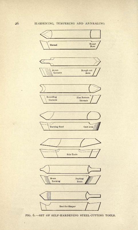
Tool Hold'er and Tools.
The engraving, Fig. 5, shows a simple home made tool holder
for lathe or planer, while Fig. 6 shows a set of tools to be used
FIG 5. A LATHE TOOL HOLDER.
HARDENING, TEMPERING AND ANNEALING.
Thread BroadNose
CornersRough oul
Slots
\ Rounding\ Corners
Flat Bottom
Threads Z7
7^ v^
Cast Iron //
V
LSide Tools
<3Brass PartingTurning Tools
<\Tool for Shaper
FIG. 6. SET OF SELF-HARDENING STEEL-CUTTING TOOLS.

STEEL, ITS SELECTION AND IDENTIFICATION 27
with it. Neither will require a description. A set of these tools
and a holder of the construction shown will be found handy
things for a tool-maker to have in his drawer.
Self-Hardening Steel Cutting Tools.
A great many machinists complain about self-hardening steel
cutting tools, and say that it is impossible to accomplish fine re-
sults in turning or planed work with them, and for that reason
a great many will not use them. Now, when they say that for
fine work they are useless, they are right, as it is impossible to
get the edges of such tools to keep a keen edge for any length
of time so as to allow of taking smooth finishing cuts. But for
medium cuts and feeds and coarse thread cutting, machiningcast iron in the shaper, planer or lathe, for turning brass castings
and also for accomplishing different operations on cast iron parts
in the turret lathe, they are unequaled and should always be used
where the production of machine parts at the minimum of cost
and labor is imperative. For the face-milling of large castings,
where inserted tooth cutters are adaptable, the self-hardening
steel tools will be found to give the best results. There are sev-
eral brands of self-hardening steel on the market in any one of
which it will be found possible to hold an edge sufficiently keen to
allow of its being used for the purposes herein enumerated.
Speeds of Cutting Tools.
To secure the best results from steel used for cutting purposes
attention must be given to the use of calculations in or for de-
termining the proper speed for the work or tool, according to
conditions. As a rule the average machinist does not in ordinary
practice make use of these rules, but instead depends on the
knowledge acquired through experience and observation. For
the benefit of those who are not familiar with rules for finding
cutting speeds, and to obviate the necessity of guessing at the
proper speed, we give approximate cutting speed at which tools
or work should be run in the machining of different metals.
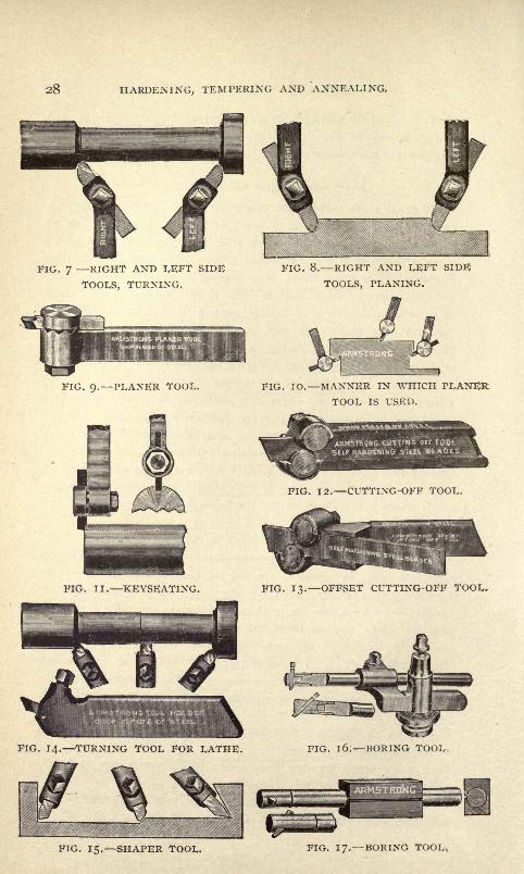
Figs. 7 to 24 illustrate tool holders and tools and the manner in
which they should be used.
Cutting speed for cast iron, 14 to 16 circumference or longi-
tudinal feet per minute.
Cutting speed for malleable iron, 16 to 20 circumference or
longitudinal feet per minute.
28 HARDENING, TEMPERING AND ANNEALING,
FIG. 7 RIGHT AND LEFT SIDE
TOOLS, TURNING.
FIG. 8. RIGHT AND LEFT SIDE
TOOLS, PLANING.
FIG. 9. PLANER TOOL. FIG. IO. MANNER IN WHICH PLANERTOOL IS USED.
FIG. 12. CUTTING-OFF TOOL.
FIG. 13. OFFSET CUTTING-OFF TOOL.
FIG. 14. TURNING TOOL FOR LATHE. FIG. 1 6; BORING TOOL,
FIG. 15. SHAPER TOOL. FIG. I/. BORING TOOL.

STEEL, ITS SELECTION AND IDENTIFICATION. 29
PIG. 19. BORING TOOL.
FIG. 22. "HOGGING " TOOL
FIG. 20. CUTTING INSIDE
THREAD.FIG. 23. PARTS OF "HOGGING"
TOOL.
ARMSTRONG THREADING TOOLDROP FORCED Of STEEL
FIG. 21. THREAD TOOL. FIG. 24. "HOGGING "CUT.
3O HARDENING, TEMPERING AND ANNEALING.
Cutting speed for steel, 12 to 15 circumference or longitudinal
feet per minute.
Cutting speed for brass, 28 to 40 circumference or longitudinal
feet per minute.
The circumstances and conditions upon which slight variations
of the speeds* given above depend are numerous, among which
are : Whether a roughing or finishing, coarse or fine cut is being
taken;the form and shape of the cutting tools
;the toughness and
density of the metals worked upon, and the surface feet machined
without regrinding the tool. There is a great deal of work done
in the lathe or in the planer which requires tools which project
far out of their holders. For such work the cutting speeds must
be considerably less than here given. Then, very often, the tex-
ture of the metal is tough and hard, necessitating slower speedsand fine feeds in machining. For these reasons, it is a difficult
matter to lay down any exact rules for the accurate calculating of
cutting speeds ;so we give approximate speeds and leave their
variation to the machinist to determine according to the various
conditions.
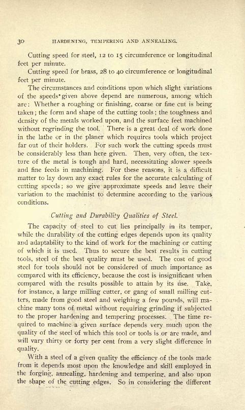
Cutting and Durability Qualities of Steel.
The capacity of steel to cut lies principally in its temper,while the durability of the cutting edges depends upon its quality
and adaptability to the kind of work for the machining or cutting
of which it is used. Thus to secure the best results in cutting
tools, steel of the best quality must be used. The cost of goodsteel for tools should not be considered of much importance as
compared with its efficiency, because the cost is insignificant when
compared with the results possible to attain by its use. Take,for instance, a large milling cutter, or gang of small milling cut-
ters, made from good steel and weighing a few pounds, will ma-
chine many tons of metal without requiring grinding if subjectedto the proper hardening and tempering processes. The time re-
quired to machine a given surface depends very much upon the
quality of the steel of which this tool or tools is or are made, andwill vary thirty or forty per cent from a very slight difference in
quality.
With a steel of a given quality the efficiency of the tools madefrom it depends most upon the knowledge and skill employed in
the forging, annealing, hardening and tempering, and also uponthe shape of the cutting edges. So in considering the different

STEEL, ITS SELECTION AND IDENTIFICATION. 31
qualities of work performed by tools made from the same gradeor brand of steel, we must first know of the amount of skill em-
ployed in the performance of the heating operations.
Judgment, Experience and Perception in the Working of Steel.
To a great many mechanics any steel which will harden is con-
sidered good steel. To harden, however, is a very simple matter,
but to harden when heated to a definite degree requires skill,
and to harden a piece of steel so that it will possess a definite de-
gree of elasticity when tempered to a particular point of tempera-ture after hardening requires skill and knowledge both. Thusif all steel which will harden is good steel, and as there is an
absence of uniformity in the grades of steel in general use, the
operator 'must rely on judgment, experience and perception to
attain satisfactory results.
Even when the steel operated upon is of a uniform grade, the
heating processes will not always bring forth uniform results,
because steel decarbonizes somewhat by being heated, and thus
a small piece or tool deteriorates by being heated in the openfire, and one often heated to repair or sharpen suffers in propor-tion. From all this it will be understood that hardening and
tempering processes of steel must differ according to the size
and nature of the work, the amount of uniformity required, and
the results which the tools are required to accomplish. Fromall these considerations we are forced to conclude that the in-
formation of value to practical men and the only way to instruct
them in the art of steel treatment is by presenting the practice of
the best shops and tool-makers and giving the processes and con-
ditions in connection with each other.
The First Effects of Heat.
Norton, in his "Elements of Natural Philosophy," says:"The first effect of heat on any body, solid, liquid or aeriform,
is to expand it.
"The expansion of gases may be readily shown by an air
thermometer. This consists simply of a bulb of glass, with a
long narrow stem, dipping into colored water. If the bulb be
warmed by the hand, the air within will so expand that a portionwill be expelled and rise in bubbles through the liquid. On cool-
ing, the portion of air remaining will contract to its former
volume, and the water will take the place of the air expelled.

32 HARDENING, TEMPERING AND ANNEALING.
"The experiment may then be continued indefinitely. The
expansion and contraction may be measured by the scale attached
to the stem;
it will be found that all expand equally and regularly
for successive increments of heat.
Unequal Expansion.
"The unequal expansion of different metals is well shown bya compound bar, made by riveting together two bars of iron and
brass, at different points along their whole length. . . .
"If the bar is straight at ordinary temperature, it will so bend
when hot water is poured on it that the brass will be on the con-
vex side of the curve, and bend in the opposite direction whencold water is poured on it. The brass expands and contracts
more than the iron, and the bar curves to accommodate the in-
equality of the length which results. This principle has been
applied to the construction of metallic thermometers.
Heat Effects on Clay.
"Clay does not expand by heat, but contracts permanently, byreason of chemical changes in its particles. In the experiments
detailed, the bodies will be found to contract on cooling and as-
sume their original volume as soon as they attain their former
temperature. Certain metals, as lead and zinc, are exceptionsto this law of cooling, the contraction being at each time a little
less than the expansion."From this experiment it is evident (i) that the volume of all
bodies is increased by heat; (2) that this increased volume is due
to motion among the molecules of the bodies, which tends con-
tinually to separate them; (3) that the intensity of the heat maybe measured by the degree of the molecular motion. From these
and other considerations it is assumed that heat is that mode of
molecular motion which may be measured by the expansion of
bodies.
"By this definition it is understood, ( i ) that the molecules of
every body are in continual motion; (2) that when this motion
increases in intensity the body becomes warmer; (3) that whenthis motion decreases in intensity the body becomes cooler. Anolder theory, which regarded heat as imponderable matter, has
been generally discarded, while some of its terms have been re-
tained; hence it must be understood that when heat is described as
passing from one body to another, it means that the molecular
STEEL, ITS SELECTION AND IDENTIFICATION. 33
motion of one body is communicated to the molecules of another,
and not that any material agent has passed between them.
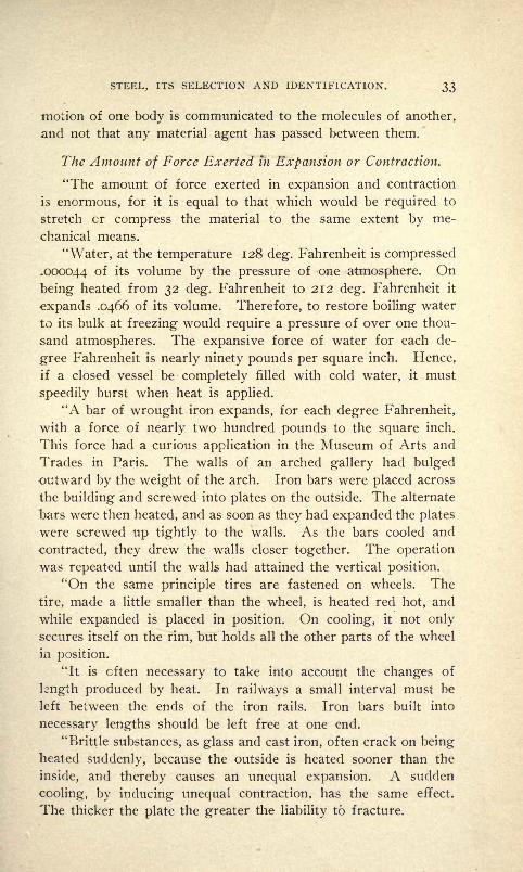
The Amount of Force Exerted in Expansion or Contraction.
"The amount of force exerted in expansion and contraction
is enormous, for it is equal to that which would be required to
stretch or compress the material to the same extent by me-
chanical means.
''Water, at the temperature 128 deg. Fahrenheit is compressed
.000044 of its volume by the pressure of one atmosphere. On
being heated from 32 deg. Fahrenheit to 212 deg. Fahrenheit it
expands .0466 of its volume. Therefore, to restore boiling water
to its bulk at freezing would require a pressure of over one thou-
sand atmospheres. The expansive force of water for each de-
gree Fahrenheit is nearly ninety pounds per square inch. Hence,
if a closed vessel be completely filled with cold water, it must
speedily burst when heat is applied.
"A bar of wrought iron expands, for each degree Fahrenheit,
with a force of nearly two hundred pounds to the square inch.
This force had a curious application in the Museum of Arts and
Trades in Paris. The walls of an arched gallery had bulgedoutward by the weight of the arch. Iron bars were placed across
the building and screwed into plates on the outside. The alternate
bars were then heated, and as soon as they had expanded the plates
were screwed up tightly to the walls. As the bars cooled and
contracted, they drew the walls closer together. The operation
was repeated until the walls had attained the vertical position.
"On the same principle tires are fastened on wheels. The
tire, made a little smaller than the wheel, is heated red hot, and
while expanded is placed in position. On cooling, it not only
secures itself on the rim, but holds all the other parts of the wheel
in position.
"It is cften necessary to take into account the changes of
length produced by heat. In railways a small interval must be
left between the ends of the iron rails. Iron bars built into
necessary lengths should be left free at one end.
"Brittle substances, as glass and cast iron, often crack on beingheated suddenly, because the outside is heated sooner than the
inside, and thereby causes an unequal expansion. A sudden
cooling, by inducing unequal contraction, has the same effect.
The thicker the plate the greater the liability to fracture.

34 HARDENING, TEMPERING AND ANNEALING.
The Second Effect of Heat.
"The second effect of heat on a solid is to change its molecular
condition to melt it. Some solids, as paper, wood and wool, do
not melt, but are decomposed. The temperature at which solids
melt differs for different substances, but is invariable for the same
substance, if the pressure is constant. This temperature is called
the melting point.
Table of Expansion from 32 dcg. F. to 212 dcg. F.
Linear. Cubical.
Solids. i i
Flint glass 1/1248 1/416
Platinum 1/1131 I/377Steel 1/926 1/309Iron 1/846 1/282
Brass 1/536 1/179Silver 1/524 I / I 75Zinc 1/340 1/113Tin 1/516 1/172
Fluids.
Mercury 1/55Water 1/21.3The fixed oils 1/12 . 5
Alcohol 1/9Air and permanent gases 180/491"
KMs of Steel Produced in America by the Crucible and OpenPIearth Processes.
Steel is produced in America by the crucible and open-hearth
processes in bars, rods, sheets, plates, wire, forgings and rolled
shapes.
The different kinds of steel produced by these methods com-
prise : Fine tool and die steel, self-hardening steel, ax and hatchet
steel, cutlery steel, surgical and fine knife steel, composite die steel,
oil well and artesian bit steel, mining drill steel, annealed die-
blocks and cutter blanks, tool steel forgings, circular and longsaw plates, boiler and fire box plates, hot-rolled and cold-rolled
strip steel, polished high-grade drill rods and wire, needle wire>
resistance wire rods, music wire rods, nickel steel rods; wire of
every grade, shape and size, bright, annealed and tempered ; cru-
STEEL, ITS SELECTION AND IDENTIFICATION. 35
cible steel rods, clock and watch spring steel, pen steel, magnet
steel, heavy gun forgings and projectiles, gun barrel steel, spring
steel, machinery steel, merchant bar steel, machinery steel forg-
ings, cold-drawn screw steel, hammer and sledge steel, welding
steel, soft center and soft back plow steel, agricultural steel of all
descriptions, sleigh shoe and toe-calk steel, wedge steel, laminated
safe steel, skate steel, etc.
One of the largest producers of steel in the world, by the cru-
cible and open-hearth processes, is the Crucible Steel Companyof America, Pittsburg, Penn. This company's products include
all of the steels above enumerated as well as many others too
numerous to mention.
CHAPTER II.
ANNEALING PROCESSES THE TERMS ANNEALING, HARDENING ANDTEMPERING DEFINED THE ANNEALING OF MALLEABLE CAST-
INGS.
The Terms Defined.
Annealing, hardening and tempering, are three terms used to
distinguish the different processes through which tool steel and
various other metals are required to pass in order to allow of their
being used for the various purposes required in the arts. In
order that the mechanic may be able to adopt these processes to
the best advantage in the making of tools for different kinds of
work, he must- learn that annealing means something more than
heating a piece of steel red hot and allowing it to cool; hardening
more than heating red hot and plunging into water, and, that
tempering, something more than coloring a piece of steel. In fact
he must realize that the annealing, hardening and tempering of
steel is an art in itself, and that in order to become skilled in it,
constant vigilance, experience and study are necessary, from "the
ground up."
Metals are annealed by slowly cooling them from a high tem-
perature. Annealing generally increases the flexibility, softness,
and ductility of bodies, and in this manner metals that have be-
come brittle through excess of strain in rolling, drawing, twisting,
hammering, forging or other mechanical means, may have their
properties restored by annealing.Steel and a number of other metals, if cooled suddenly after
having been heated to a high temperature, become more brittle andmore elastic than before. For instance, if a piece of tool steel is
heated to a white heat and then plunged into a bath of ice-water
or mercury, it will become almost as hard as a diamond, and will
be very elastic and so brittle that it can only be used for drilling
tempered steel or chilled iron, or for coining and engraving dies
and files of the hardest kinds.
When steel is in its softened condition it may be worked into
any shape required in the arts. To harden steel after it Has been
worked, it is strongly heated and suddenly cooled, and as it is
rendered too brittle by this hardening process (for ordinary pur-

ANNEALING PROCESSES. 37
poses, at least), something of its elasticity must be sacrificed and a
portion of its hardness removed by reheating the steel to a lower
temperature and allowing it to cool slowly. This process is called
"drawing" or "tempering." The temper to which a piece of steel
should be drawn depends upon the use to which it is to be put,
and is regulated by varying the temperature of the second heat-
ing, the higher the degree of heat the softer the steel.
When a steel tool or article has been hardened, then polished
or ground and reheated, the film of oxide on its surface becomes,
at a temperature of 420 deg. F., of a light straw color, then
through intermediate hues to a violet yellow at 509 deg. F., blue
at 550 deg. F., while at 725 deg. F. the steel passes to a red heat.
These colors guide the workman in his efforts to temper the
tools as required. Light yellow is the temper required for all
articles or tools requiring a keen edge ;a deeper yellow for fine
cutlery, while violet is the temper for table knives requiring flexi-
bility more than a hard brittle edge, and blue for all articles or
tools which are required to be very flexible.
How to Thoroughly Anneal High-Carbon Tool Steel Parts.
Very often a large number of accurate small tools are to-be
made from high-carbon steel, and as they are required to be
hardened perfectly so as to not warp, bulge, crack or shrink ex-
cessively, they must be perfectly annealed before finishing.
The most satisfactory method for annealing high grade tool
steel parts is to pack in granulated charcoal in an iron box, ar-
ranging the parts so that they will not come higher than within
one inch of the top of the box, and cover with well packed char-
coal. Then place the box in the furnace or forge and heat to a
bright red, at which it should be held for some time, depending
upon the size of the parts to be annealed. For instance, parts
not over one inch in diameter or thick, if kept at a red heat for
an hour, after a through heat, will be found to have annealed as
desired ; large pieces must be kept hot for a period correspond-
ing to their size and shape. After the heat, allow the box to
cool off slowly and do not remove the parts until perfectly
cool.
The Proper Heat for Annealing.
It has been found through experience that the proper Heat
for annealing is almost a forp-in^ he?>t. Keep at a bright red
long enough to overcome all strains which may have a tendency
ft
38 HARDENING, TEMPERING AND ANNEALING.
to manifest themselves during the hardening process. It is not
well to use cast iron chips or turnings for packing, as they will
decarbonize the steel to such an extent as to prevent successful
hardening afterward. Packing parts too near to the walls of
the annealing box will have almost the same effect as the chips ;
in fact, it will be worse, as the decarbonizing effect will be unequaland the surfaces nearest the box sides will be affected, thus mak-
ing whatever hardening possible unequal.
Annealing in the Charcoal Fire.
A great many shops have not the facilities to allow of using
the above described annealing process, and in such very satisfac-
tory results may be attained by heating the steel in a good char-
coal fire to about an even forging heat. After heating, put a
few inches of the fire ash in a box, and on top of the ash place
a soft pine board, then place the heated work on top and cover
the box. TRe wood will char and smolder and the steel will re-
main hot for a considerable period. Often a box of cold ashes
may be used to accomplish the same results to a less extent, as the
cold ashes or lime either one acts the same are apt to chill the
hot steel. However, when either of the three materials are used
hot, good results will be obtained.
Good Steel for Good Tools.
One of the points that a great many mechanics seem to forget
is the necessity of having good steel in order to do good tool-
making. Often upon asking a toolmaker, who was engaged in
making a tool or die, what brand of steel he was using, the
writer has been met with the answer: "I don't know." Make it
your business to discover the best brands for different purposes
and then stick to them. A steel that is good steel will show, when
hardened and broken, a white fracture free from coarse spots.
Get a steel of a carbon percentage that will allow of its being an-
nealed and hardened at a low red heat, as steel which requires
a very high heat to anneal and harden, will, nine times out of ten,
prove utterly unsatisfactory, and tools made from it will crack,
chip or spring when in use.
Annealing.
Although it does not seem to be generally known, the suc-
cessful hardening of a piece of steel depends greatly on the an-

ANNEALING PROCESSES. 39
nealing of it previous to machining it, and in order to harden
properly it is necessary that the correct processes of annealingshould be understood. Always anneal any odd-shaped piece, or
one with an irregular-shaped hole in it, after having roughed it
down. The best way to anneal such pieces is to pack them in
charcoal in an iron box, being sure to have as much charcoal at the
sides of the box as at the bottom, in order that the heat shall not
penetrate too quickly. The box should be kept at a red heat for
an hour, and then left in the ashes over night to cool. The properheat for such pieces in annealing should always be higher than the
heat required to harden the same piece. Experience has taughtus that a heat almost as high as a forging heat will be the means
of overcoming any undue tension or strain which may become ap-
parent when the piece is hardened.
An Annealing Bo.v for Small Parts.
A good way to make an annealing box for small parts is to take
a piece of, say, 3-inch iron pipe about 10 inches long. Tap both
ends of the pipe and fit plugs to them; cast iron will do. One of
the ends may then be closed and the charcoal and parts to be an-
nealed packed in, after which the other plug can be screwed in.
With a box of this kind no sealing is necessary, as the screw plugs
prevent the entrance of the air.
Water Annealing.
Very often a piece of steel is required for a repair job or some
other job in a hurry, and there is no time to anneal it in the regu-
lar way. At other times a piece which has been hardened re-
quires to be machined. When confronted with the above condi-
tions, a tool-maker can fall back on the "water annealing" and
after he has tried it a few times he will be delighted with the re-
sults. There are several methods of doing this, and we give here
the best of them all : The mechanic may adopt any of them, accord-
ing to the results secured from each. The first method is to heat
the steel slowly to a dull cherry red;then remove it from the fire
and with a soft piece of wood try the heat, as it decreases, by
touching the steel with the end of the stick. When the piece has
cooled so that the wood ceases to char, plunge the steel quickly
into an oil and water bath. On machining the steel it will be
found to be very soft.
The second method for water annealing is to heat the steel
4O HARDENING, TEMPERING AND ANNEALING.
slowly to a red heat, then allow it to lie in the ashes a few min-
utes until almost black, then drop it into soapsuds and allow it
to cool.
Very often a piece of steel annealed in this manner will turn
out much softer than if annealed in the regular manner by packingin powdered charcoal and allowing it to cool over night. A good
way to make sure as to the time to drop the steel into the bath,
is to allow it to cool until almost black, then touch it with a file,
if the steel does not brighten for an instant and then turn blue,
wait a few seconds and repeat the experiment. If, upon the
second trial, the blue appears and then a spark right afterward,
drop the steel instantly into the bath, and when cool it will be
found to be as "soft as butter."
Sometimes a piece of steel which is to be used as a punch or
die blank, upon starting to machine it, proves hard, although it
has been annealed. When this is the case, never try to finish it
before reannealing it; instead, rough it down, clean out the cen-
ters and anneal it over again. The time required to rqanneal a
piece of steel will be more than made up in the machining of it.
The Effects of the Water Anneal.
Although it may seem strange to some, it is a fact that results
possible to attain in steel which has been water annealed cannot
be obtained by any other methods. Water annealing seems to
give a certain texture to the grain of the steel, which is not ex-
actly softness, but is different from that obtained by charcoal ash
annealing. When a piece of steel has been properly water annealed
and is turned in the lathe using a lubricant, it will present a
strange dead-white appearance and the turnings will be short
and come off like little bristles.
In steel annealed in the usual manner the turnings will gen-
erally come off in long close-curled lengths, and the surface
of the work will present a more or less torn texture, even when
the tool used is very keen. This tearing is caused by the steel
being so soft as to give way and crowd up into little lumps just
slightly ahead of the cutting edges of the tool. Thus in cutting
screw threads in ordinary annealed steel it is almost impossible to
get a smooth, clean thread.
The water annealing, however, seems to overcome this un-
pleasant feature, in that it seems to give the requisite stiffness
of texture to prevent this tearing. Considering the results, the

ANNEALING PROCESSES. 4!
water anneal will contribute to the best results being attained in
a large variety of lathe work.
We are unable to state just what chemical or molecular action
the water anneal has on steel. It is not a softening action, as
compared with the effects of ordinary annealing, but instead a
stiffness and tightness of the particles which allows the cutting
edge of the tool to creep beneath the shell and peel it off.
The Annealing of Tap Steel.
Most of the large establishments in which taps, reamers, etc.,
are manufactured have most of their steel annealed at the places
where it is made. This has been done for some years with the
possible exception of the steel from which long stay-bolt taps
are made, they having been found to require more care in anneal-
ing than the steel manufacturers give them.
During an interview a few years ago, Mr. F. A. Pratt, of the
famous American firm of Pratt & Whitney, spoke as follows in
regard to the working of tap steel :
"We have most of our tap steel annealed at the place where
it is made. We have had it done in this way for some years, with
the exception of our long stay-bolt taps, which we have found
to require more care in annealing than the steelmakers give them.
"More steel is injured, and sometimes spoiled, by over-anneal-
ing than in any other way. Steel heated too hot in annealing will
shrink badly when being hardened; besides, it takes the life out
of it. It should never be heated above a low cherry red, and it
should be a slower heat than it is when being hardened. It should
be heated slowly and given a uniform heat all over and through
the piece.
"This is difficult to do in long bars and in an ordinary furnace.
The best way to heat a piece of steel, either for annealing or
hardening, is in red hot, pure lead. By this method it is done
uniformly and one can see the color all the time. We do some
heating for annealing in this way, and simply cover up the piece
in saw-dust, and let it cool there, and we get good results. All
steelmakers know the injurious effects of over-heating steel and of
over-annealing, but their customers are continually calling for
softer steel and more thorough annealing. Until users are edu-
cated up to the idea of less annealing and to working harder steel,
both will suffer, for the user will continually complain of poorsteel.

42 HARDENING, TEMPERING AND ANNEALING.
"Several years since we caught on to the fact that steel was
injured by over-annealing, and that good screw threads could not
be cut in steel that was too soft;our men would rather take the
steel bar direct from the rolls without any annealing than take the
risk of annealing. At present we get it from the makers in passa-
ble condition, but not as it should be, and unless the steelmakers
find some way to heat the bars to a uniform heat, and at a low
cherry red, we must either use it raw from the bar or anneal
it ourselves. We find, also, that this soft annealing makes a much
greater shrinkage and spoils the lead of the thread, and that from
the bar without any annealing there is very little trouble in this
respect.
"When O. H. and Bessemer machine steel was first introduced
it was poorly made and hard to work. Users constantly urgedthe makers to make it softer, until when a maker could say his
steel was as soft as iron, and not more than o.io to 0.15 of i percent, carbon, he had the market. This company found out early
that this soft machine steel was almost worthless. A shaft would
bend easily in working, and if a lead screw was to cut it was not
possible to get a smooth thread and a good finish.
"Now we either make shafts and spindles of cast steel of a
high carbon or of machine steel of about 50 per cent carbon, with-
out annealing. Our men kicked at first, but now they complainif it is soft, because they cannot cut a good thread and cannot keepit as true."
Re-Annealing Tap Blanks.
Often, from improper annealing, a tap blank proves too hard
for thread cutting, this coming about in the annealing processes,
from not heating properly or not knowing the nature of the steel.
When this is the case always re-anneal the blank, and the loss
of temper and wearing out of good tools in trying to cut a thread
on too hard stock will be obviated. Before re-annealing take a
rough cut-off and clean out the centers.
How to Heat for Annealing.
When annealing steel, heat very slowly to a red never heat
it hot enough to raise scale and allow lots of time for cooling.
A piece of steel heated hot enough to scale will never work well
unless re-annealed by some method which will restore it from its
almost burnt state.

ANNEALING PROCESSES. 43
Annealing a Small Quantity of Steel.
When only a small quantity of steel is required heat to a
cherry red in a charcoal fire and pack in sawdust in an iron box.
Keep the steel in the pack until cold. For a large quantity, which
is required to be very soft, pack with granulated charcoal in an
iron box as follows : Having at least % or y\ inch in depth of
charcoal in the bottom of the box, add a layer of granulated char-
coal to fill spaces between the steel, and also l
/2 or }4 inch space
between the side of the box and the steel, then more steel, and
finally i inch in depth of charcoal well packed on top of the steel.
Heat to a red and hold for from two to three hours and do not
remove the steel from the box until cold.
Annealing Steel in the Open Fire.
Although the annealing of steel can be best accomplished bysome of the regular packing materials, there are cases, such as an
emergency job, when this cannot be resorted to, because of the
time necessitated. When a piece of annealed steel is wanted in a
hurry, try heating in an open fire and water annealing heating
in a charcoal fire to a dull red, then letting the steel cool natur-
ally in the day light until the red disappears, and then quenchingin cold water.
Quick Methods for Softening Steel.
In the following we give a few methods for the quick anneal-
ing of steel, gathered from various sources :
Cover over with tallow, heat to a cherry red in a charcoal fire
and allow it to cool itself.
Heat the steel to a low cherry red and allow to cool in a dark
place until black. Then quench in the juice or water of common"beans.
Cover with clay, heat it to a cherry red in a charcoal fire and
allow to cool slowly.
To Anneal Doubtful Steel.
There are some kinds of steel which will not anneal satisfac-
torily even when packed in air-tight boxes in powdered charcoal.
To anneal steel of this kind, cover it with fine clay and heat to
a red heat and allow it to cool over night in the furnace.
Annealing Chilled Cast-Iron Dies for Drilling.
As drawing and forming dies are often made of chilled cast
44 HARDENING, TEMPERING AND ANNEALING.
iron, and as not infrequently holes are required to be drilled in
them, it is well to know how to soften it to allow of drilling the
holes. To do this, heat the die to a cherry red and let it lie on
the coals. Then place a piece of brimstone, circular in shape and
a little larger in diameter than the hole to be drilled, on the spot
where the hole is to be. Let the die lie in the fire until it has died
out and the metal has cooled, and the brimstone will have softened
the iron entirely through within the radius of its diameter when
solid.
Annealing White or Silver Iron.
To anneal white or silver iron so that it may be drilled or
chipped, put it into a steel furnace or other converting furnace
together with a suitable quantity of ironstone, iron ore, some of
the metallic oxides, lime, or any other combination of these sub-
stances reduced to a powder, or any other substance capable of
combining with or absorbing the carbon of the crude iron. The
more or the longer the heat is applied, the more nearly malleable
the iron will become.
The Annealing of Malleable Castings and the Manufacturing of
Malleable Iron Machine Parts.
One of the largest establishments in this country devoted to
the manufacture of malleable iron machine parts, is situated in
Hoosick Falls, N. Y., and is controlled by the Walter A. Wood
Mowing and Reaper Machine Company. A description of their
plant, methods, etc., will tend to an intelligent understanding of
how malleable iron machine parts are produced.
The Foundry and Preparation of the Castings.
The malleable department, exclusive of its sheds, has a floor
space of over 163,000 square feet, the foundry alone measuring
485 x 125 feet. In this department, in which 350 men are em-
ployed, of whom 135 are molders, there are three furnaces with a
capacity of three heats each in a twelve-hour day. The largest
furnace, almost at the entrance of the foundry, will melt fourteen
tons of metal at each heat, while the other two in the center of
the foundry and at the extreme end, respectively, will each melt
ten tons.
The castings produced are mostly of small size and are madefrom gated patterns. After they have been removed from the
molds they are broken from the gates and are sent to the preparing
ANNEALING PROCESSES. 45
department, where they are sorted, and all lumps, fins and gate
joints are removed. The castings as they come from the molds are
almost as brittle as glass and it is possible to split or break them
with a light blow of a hammer. It is very interesting to watch
the men in this operation. They can take a casting, set the
edge or lump to be removed on an iron block and break it off
at the joint with one blow, leaving the portion where the joint
was as smooth as the rest of the casting.
Annealing Furnaces Packing the Castings.
After the castings have been sorted and prepared they go to
another department to be packed into the annealing pots. These
pots are cast, and are about 24 inches long, 12 inches deep and
12 inches wide, and an inch thick. A mixture consisting of
common sand, fine steel turnings and steel scale from the rolling
mills is then wet with sal-ammoniac (which prevents the steel
turnings and scale from adhering to the castings during the an-
nealing process) and packed around the castings in the annealing
pots. The pots are now taken to the annealing room. In this
room there are eight ovens, the walls of which are three feet
thick and the tops and bottoms four feet thick. To build each of
these ovens 4,500 red brick and 1,500 white or firebrick were re-
quired. In each oven there are flues three feet square, running
the full length of the oven and out into the stack at one end.
There is also one intermediate flue, and a flue at each side into
which the crude oil blast is fed.
Different Methods of Packing Castings in Pots.
There are various methods for packing castings for annealing.
The term "packing" is a shop One applied to the class of materials
which are used for the above purpose, and in addition, supply
oxygen or have the latter in their composition. A number of
different materials are used for the former purpose which are
'used principally on lighter castings. Almost anything that will
stand up well while hot is suitable, like ground burned fire brick,
iron borings, and sand. As they of themselves do not supply
oxygen, it is necessary in using them that oxygen be obtained
by means of a coating of rust or oxide upon the castings either
before or after charging the pots. In rusting them before, much
of the oxide becomes rubbed off in packing. Packing the cast-
ings wet will do, provided there is some certainty of their being
46 HARDENING, TEMPERING AND ANNEALING.
oxidized before heating. Wetting the packing with diluted am-
monia is a very sure means, and is the most satisfactory way of
handling this material.
Packing or charging castings in the pots, so that they retain
their shape and do not scale or warp while hot, is a process that
cannot be well described. In general, they should be packedwith a view to keeping the packing in close contact with the
castings during the settling of the contents of fhe pot. For in-
stance, flat plates or sections should be packed on edge ;if on the
side, they will scale on the bottom, from which the packings have
settled. This explains why some castings scale and others da
not in the same pot. Castings having projections or unequal
sides, which can therefore be stacked on top of each other, are
built up from the bottom plate with a view to balancing the pile.
All long sections and long castings, unless packed in pots that
will admit of their being placed horizontal, should be set uponthe bottom plate vertically. I have seen castings 5 feet longbecome y^ inch longer than the pattern, because they were packedsome inches above the bottom plate and hung in the pot during-
settling. As a general rule, there is a relation between the amount
of the packing and the castings, or between the oxygen in the
packing and the carbon in the castings ;there can therefore be a
condition where there is not sufficient packing between the cast-
ings to anneal. There should always be an excess in favor of the
packing. The packing of the castings is carried upward with a
view to meeting the unequal heating of the pots that is, heavy
castings in the top and light ones in the bottom, separated byplates when the occasion requires it. Beginning \vith the bottom
plate, the first pot is usually a new one. They do not take the
heat readily, on account of the sand upon them, and for this
reason should be broken in on top. Owing to their weight, how-
ever, it is not practical to use them there. Building or packingcontinues upward, the pots being placed according to their age,
the top pots passing through the service.
Annealing, Straightening and Finishing of Malleable Castings.
In the malleable department of the Wood works, in each an-
nealing oven, pots containing twenty tons of castings are
packed as close together as possible, after which the vents and
doors are sealed up and the ovens are heated. It requires twen-
ty-four hours of steady blast to get the ovens and castings to a

ANNEALING PROCESSES. 47
white heat. They are then kept at that temperature for five daysand five nights, after which the blasts are turned off and the
vents at the tops of the ovens opened. After the vents have been
open for five hours the door is pulled down and five hours later the
nearest pots are removed, and in the course of a few hours the
others are taken out and allowed to cool. They are then dumpedand the castings are sorted. All that have cracked or blistered
or have warped excessively are thrown out. The good castings
are then sent to the straightening department to be straightened
and reformed, so as to fit the jigs and fixtures which are used
for machining those which are required to be machined and to
make the others interchangeable. The straightening and re-
forming of the castings are accomplished by dies in powerful
presses. There are seven different machines, one a hydraulic
press of seven tons, one five-ton power press, and two powerful
drop hammers. On shelves surrounding the straightening roomare hundreds of sets of dies. The dies for the large castings are
of gray iron, while those for the small parts are of hard iron.
The dies are cast in the department's own foundry by first gettinga plaster model of the inside of the master patterns and one of
the outside and then casting the dies from this model.
After the straightening and re-forming process, the castingsare sent to the grinding and finishing department. Here all
lumps and fins which were not removed before the annealing are
ground off. The parts to be machined are finished in special
jigs and fixtures on the drill press, milling machine or lathe, as
most suitable, and the castings are then ready for the storeroom.
As every size and style of casting produced in the foundry is
numbered, and as the numbers run from i to 2,503, some idea maybe formed of the storage space required. The patterns used are
of composition metal. They are stored in a fireproof vault, 65
by 25 feet and 12 feet high.
Heating the Annealing Ovens.
To heat the annealing ovens, crude petroleum is used, the oil
being pumped from three tanks sunk in the ground 300 feet from
the ovens and 200 feet from the engine-room in which pumps are
located. One tank holds 13,000 gallons of oil and the other two
6 ooo gallons each. The large tank is located beneath the rail-
road track and is filled from tank cars, and this in turn fills the
small ones. The pump used to pump the oil to the annealing1

48 HARDENING, TEMPERING AND ANNEALING.
ovens runs continually and has not been shut down twelve hours
in a year. To melt the iron used in the malleable iron foundrysoft coal is used, the furnaces being so constructed as to allow
of the coal being placed in the front part and the metal and other
materials required to produce hard iron at the back, the heat
being driven in on the mixture by air pressure.
General Matter Relative to Malleable Iron Manufacturing.
Mr. Robert Leith, the superintendent of the department, has
been with the Wood Company for twenty-five years, and has been
responsible for the many innovations in his department tending
to economic production, one of which is to use in his foundry all
cf the scrap steel produced in the main works. He has used 100
pounds of the scrap steel to every ton of iron, and has secured the
very best of results by so doing. Formerly it was necessary to
sell the scrap steel for almost nothing, in comparison with its
cost to the firm, but now the malleable department disposes of
all of it. The output from the malleable department per week
is usually 150 tons of good castings, the bad work coining from
the foundry and annealing department not being counted. The
power required for the department is derived from a 150 horse-
power engine, which has been in use over twenty-five years, and is
to-day a fine example of what care and a good engineer can do
for an engine in regard to its longevity.
On the harvesting machinery manufactured by the Wood
Company a great deal of chain is used. The links composingthese chains are produced in the malleable department and the
chains are assembled and finished there. The links are cast from
gated patterns, as many as fifty links to each mold. The gatingis done in such a manner that when the castings have been
broken from the gate bars very little irregularity of surface is
evident; what projections remain are ground off after the anneal-
ing process. The chains are assembled in continuous lengths byan automatic machine, the links being fed through a chute at the
front and the chain fed out automatically at the back. Thechains are subjected to various tests to insure their being the
length required. Often (as the links are not machined before as-
sembling) some of the chains will be shorter than required, this
coming about through unequal rapping when molding, etc., the
part where the links unite being thicker in some than in others,
the accumulation in the course of a number of links making quite

ANNEALING PROCESSES. 49
a difference in the length of the chain. This defect is overcome
by means of another machine, in which the chains are stretched
until they are of the required length.
There is a metal pattern shop connected with the departmentir> which all the patterns used in the foundry are finished. In
this shop some of the finest metal pattern-work that I have ever
seen is turned out, as is evidenced by the fact that out of a thou-
sand castings of a certain shape only two were found to be "off"
enough to prevent their being machined in the fixtures providedfor them. Besides producing all the malleable castings which
the works require, the department also does custom work, and it
has the reputation of having done some of the finest work in the
country.

CHAPTER III.
THE HEATING AND COOLING OF STEEL LOCATION OF HEATING
ARRANGEMENTS THE USE OF GAS BLAST FURNACES AND
HEATING MACHINES TOUGH STEEL AND HARD STEEL; THE.
DIFFERENCE.
The Heating and Cooling of Steel.
There are any number of shops in which a great deal of un-
necessary expense is incurred in the annealing, hardening and
tempering of steel through improper heating and cooling during
the processes ;and while often inexperience is the cause of such
expense, more often the crude and obsolete means employed for
heating and cooling are to blame.
The fact is obvious to all that where expensive tools are
made, proper facilities should be provided for the heating proc-
esses through which they are put. If there is any economy in
providing fine machine tools and employing skilled mechanics
to make fine small tools and utterly ignoring the requirements for
the annealing and tempering of them, we fail to see it.
Now, while a plain ordinary forge is all right and will be
found to be all that is necessary for the annealing and temperingof rough tools, it will not do for fine ones. When it is considered
that an accurate cutting tool which has been annealed properlybefore finishing, and then carefully and accurately hardened and
tempered afterward, will accomplish many times the amount of
work that an imperfectly treated one will, the expense incurred
in providing suitable heating facilities is insignificant, when the
longevity of the tools treated is considered. In shops where a
fair number of fine cutting tools are made and used, the cost of
proper heating arrangements will be made up in a short time bythe money saved through the use of properly hardened and tem-
pered tools. Another thing: after having installed a suitable
hardening plant, hire a mechanic to run it who understands the
treatment of steel. With this combination, and a supply of good
high-grade steel, there will be no dissatisfaction with the working
qualities of the cutting tools ; if there is, there will be no excuse
for it;carelessness will be to blame.
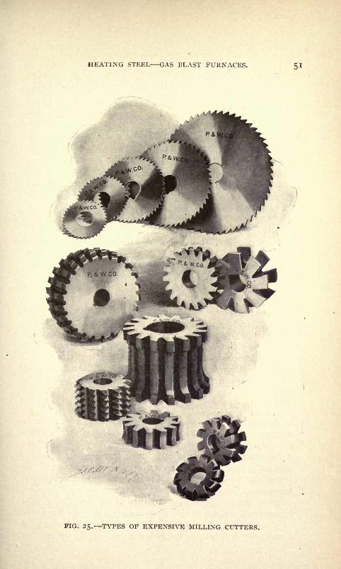
HEATING STEEL GAS BLAST FURNACES.
FIG. 25. TYPES OP EXPENSIVE MILLING CUTTERS.
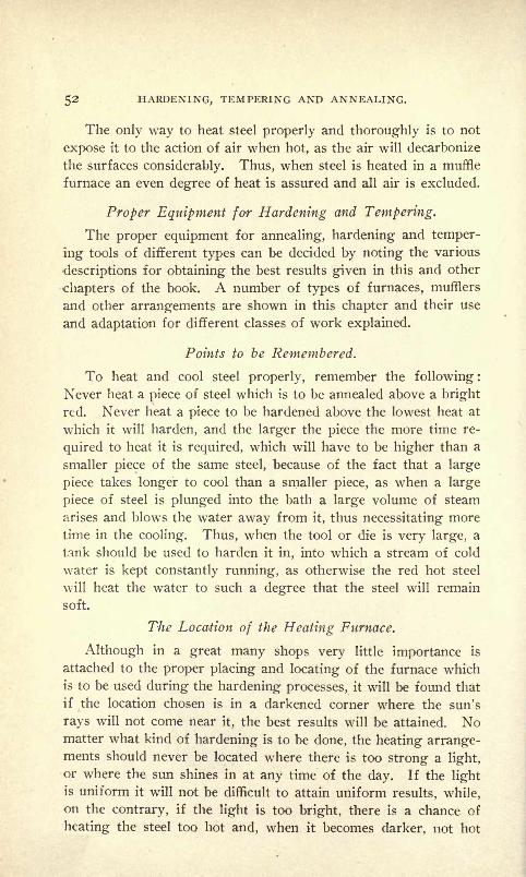
52 HARDENING, TEMPERING AND ANNEALING.
The only way to heat steel properly and thoroughly is to not
expose it to the action of air when hot, as the air will decarbonize
the surfaces considerably. Thus, when steel is heated in a muffle
furnace an even degree of heat is assured and all air is excluded.
Proper Equipment for Hardening and Tempering.
The proper equipment for annealing, hardening and temper-
ing tools of different types can be decided by noting the various
descriptions for obtaining the best results given in this and other
chapters of the book. A number of types of furnaces, mufflers
and other arrangements are shown in this chapter and their use
and adaptation for different classes of work explained.
Points to be Remembered.
To heat and cool steel properly, remember the following :
Never heat a piece of steel which is to be annealed above a bright
red. Never heat a piece to be hardened above the lowest heat at
which it will harden, and the larger the piece the more time re-
quired to heat it is required, which will have to be higher than a
smaller piece of the same steel, because of the fact that a large
piece takes longer to cool than a smaller piece, as when a large
piece of steel is plunged into the bath a large volume of steam
arises and blows the water away from it, thus necessitating more
time in the cooling. Thus, when the tool or die is very large, a
tank should be used to harden it in, into which a stream of cold
water is kept constantly running, as otherwise the red hot steel
will heat the water to such a degree that the steel will remain
soft.
The Location of the Heating Furnace.
Although in a great many shops very little importance is
attached to the proper placing and locating of the furnace whichis to be used during the hardening processes, it will be found that
if the location chosen is in a darkened corner where the sun's
rays will not come near it, the best results will be attained. Nomatter what kind of hardening is to be done, the heating arrange-ments should never be located where there is too strong a light,
or where the sun shines in at any time of the day. If the lightis uniform it will not be difficult to attain uniform results, while,
on the contrary, if the light is too bright, there is a chance of
heating the steel too hot and, when it becomes darker, not hot
HEATING STEEL GAS BLAST FURNACES. 53
enough. When a uniform light is maintained during the day the
men become accustomed to it and no trouble is experienced in get-
ting the best of results.
The Use of Gas Blast Furnaces and Heating Machines.
The use of gas blast furnaces and heating machines has nowbecome so extensive as to have almost completely superseded the
old methods, and the furnaces and machines are now used in se-
curing the highest possible efficiency in the use of heat for me-
chanical purposes as well as in the processes of metallurgy and
chemistry.
Gas blast furnaces are designed for the economical use of gasas fuel in forges, crucible furnaces, annealing, enameling, case-
hardening ovens, assaying, cupeling and other muffle furnaces,
japanning ovens, and drying and baking kilns, in all of which
the heat is generated by a properly proportioned mixture of gasand air, injected under positive pressure, through burners espe-
cially adapted to each of the different kinds of gas in commonuse.
Heating machines may be called "modern machine tools,"
made for special heating processes, as they are combinations of
gas furnaces and moving machinery for the automatic feeding
and discharging of work which is to be annealed, hardened, tem-
pered or forged in quantities.
The chief advantages derived from the use of gas as a fuel are
the perfect adjustment of temperatures to suit exact require-
ments, which is impossible with either solid or liquid fuel;
the
ease with which any desired degree of heat can be obtained by
simple adjustments of two valves, the uniformity of its distri-
bution within given space, the partial or complete absence of oxida-
tion, and, generally, the perfectly uniform condition under which
any heating process can be performed irrespective of the quanti-
ties of work to be heated.
The gas consumption, cost of gas as compared with other
fuel, while an important factor in determining the adoption of
gas furnaces for the cruder operation of melting or forging,
scarcely deserves consideration with reference to furnaces or
heating machines for hardening, tempering or annealing large
quantities of work, because no approximately equal amount of
perfect work can be produced by the use of any other fuel than
gas.

54 HARDENING, TEMPERING AND ANNEALING.
Gas Blast Forges Their Use.
Gas blast forges heat the work quickly, uniformly, and with
little or no scale. They are always ready for use and develop
the required amount of heat in a few minutes. They are used in
machine shops for tool dressing and forging ;in the production of
quantities of small forgings, such as cutlery, and for drop forg-
ings generally.
While offering decided advantages, no single gas forge or
furnace can replace the ordinary coal forge in everything, because
to be thoroughly effective, as well as economical in gas con-
sumption, the gas forge must be made for a definite range of
work, and its heating space limited so as to conform to its size
and shape, with only fair allowance for clearance space.
In order to determine the applicability of any of the various
styles of gas forges now on the market, the dimensions of the
entrance, height, width, depth, and length of the heating chamber
must be considered, and a fair allowance made for clearance.
When samples of work to be done are furnished to the manu-
facturers of such machines, together with a statement of the
quantities to be heated in any given time, they will design special
forges.
When gas blast forges are used in forging the overheating of
the metal is entirely prevented, a non-oxidizing atmosphere re-
ducing the scale to a minimum, thus supplying properly heated
stock as fast as it can be handled.
For welding, special forges should always be designed for any
particular kind of work, so that the blast will be confined closely
to the joint to be made. In welding tires, the diameter, width
and thickness will determine the shape of the entrance to the forgeand conform to it.
Combination Gas Furnace for General Machine Shop Work.
In Fig. 26 we illustrate a combination gas furnace ready to
operate.
This furnace combines on one base three most useful furnaces
for general machine shop and tool work. It will heat quicklyand uniformly any piece or pieces that will go into its various
openings. The muffle can. be heated to a good heat for hardeningin from ten to twelve minutes and kept at the desired temperature
indefinitely. The forge will heat a piece I inch round to a good

HEATING STEEL GAS BLAST FURNACES. 55
hardening heat in one minute, starting with the furnace cold.
The crucible full of lead can be heated to cherry red in about
thirty-five minutes.
A furnace of this type occupies very little room; does not
require to be connected to chimney; can be placed right in the
tool room or anywhere it is most convenient; can be started in-
stantly, and covers a range of uses that makes it practically indis-
pensable. All sorts of small tools, such as dies, milling cutters,
FIG. 26. COMBINATION GAS FURNACE.
reamers, punches, taps, drills, springs, cutlery, marking rolls,
etc., can be heated in the muffle under the best possible condi-
tions.
A section of this combination furnace, showing the muffle
with walls cut away to illustrate arrangements of combustion
chamber and muffle, is shown in Fig. 27.
The flame is projected from the double burners downward into
the chamber encircling the muffle ; the lining is of such shape that
a rotary motion is imparted to the flame, causing same to distri-
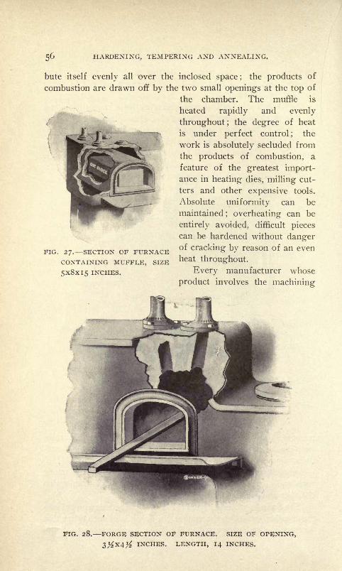
56 HARDENING, TEMPERING AND ANNEALING.
bute itself evenly all over the inclosed space ;the products of
combustion are drawn off by the two small openings at the top of
the chamber. The muffle is
heated rapidly and evenly
throughout; the degree of heat
is under perfect control; the
work is absolutely secluded from
the products of combustion, a
feature of the greatest import-ance in heating dies, milling cut-
ters and other expensive tools.
Absolute uniformity can be
maintained; overheating can be
entirely avoided, difficult pieces
can be hardened without dangerof cracking by reason of an even
heat throughout.
Every manufacturer whose
product involves the machining
FIG. 27. SECTION OF FURNACECONTAINING MUFFLE, SIZE
5x8x15 INCHES.
FIG. 28. FORGE SECTION OF FURNACE. SIZE OF OPENING,INCHES. LENGTH, 14 INCHES.
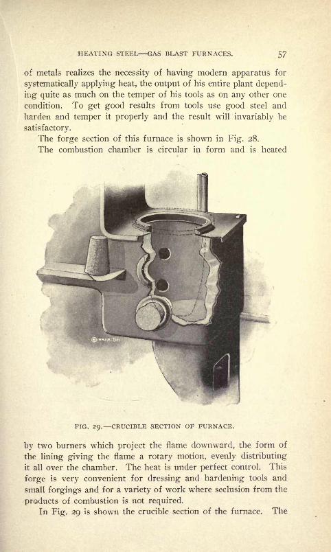
HEATING STEEL GAS BLAST FURNACES. 57
of metals realizes the necessity of having modern apparatus for
systematically applying heat, the output of his entire plant depend-
ing quite as much on the temper of his tools as on any other one
condition. To get good results from tools use good steel and
harden and temper it properly and the result will invariably be
satisfactory.
The forge section of this furnace is shown in Fig. 28.
The combustion chamber is circular in form and is heated
FIG. 29. CRUCIBLE SECTION OF FURNACE.
by two burners which project the flame downward, the form of
the lining giving the flame a rotary motion, evenly distributing
it all over the chamber. The heat is under perfect control. This
forge is very convenient for dressing and hardening tools and
small forgings and for a variety of work where seclusion from the
products of combustion is not required.
In Fig. 29 is shown the crucible section of the furnace. The
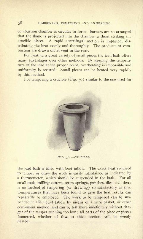
5 HARDENING, TEMPERING AND ANNEALING.
combustion chamber is circular in form; burners are so arranged
that the flame is projected into the chamber without striking ti.^
crucible direct. A rapid centrifugal motion is imparted, dis-
tributing the heat evenly and thoroughly. The products of com-
bustion are drawn off at vent in the rear.
For heating a great variety of small pieces the lead bath offers
many advantages over other methods. By keeping the tempera-ture of the lead at the proper point, overheating is impossible and
uniformity is secured. Small pieces can be heated very rapidly
by this method.
For tempering a crucible (Fig. 30) similar to the one used for
FIG. 30. CRUCIBLE.
the lead bath is filled with beef tallow. The exact heat required
to temper or draw the work is easily maintained as indicated bya thermometer, which should be suspended in the bath. For all
small tools, milling cutters, screw springs, punches, dies, etc., there
is no method of tempering (or drawing) so satisfactory as this.
Temperatures that have been found to give the best results can
repeatedly be employed. The work to be tempered can be sus-
pended in the liquid tallow by means of a wire basket, or other
convenient method, and can be left there indefinitely without dan-
ger of the temper running too low;
all parts of the piece or pieces
immersed, whether of thin or thick section, will be evenly
heated.

HEATING STEEL GAS BLAST FURNACES, 59
Gas Forge for Small Work.
The gas forge shown in Fig. 31 is of a type commonly used
for dressing and hardening tools and smaller forgings. The
heating chamber is circular inside, and its capacity is limited hr
I
FIG. 31. GAS FORGE. ENTRANCE, 6 INCHES WIDE BY 3 INCHES
HIGH; DEPTH OF HEATING SPACE, 6 INCHES.
the size of the entrance to the heating chamber, and a correspond-
ing opening in the back is ordinarily closed by a "plug," which
can be removed when a clear passage through the furnace is re-

6o HARDENING, TEMPERING AND ANNEALING.
quired. Two burners project into the heating chamber from the
distributing pipe, D, W, so adjusted that direct contact of the
flames with the work is avoided. Perfect combustion is steadily
maintained, the work is quickly and evenly heated and oxidization
reduced to a minimum.
The furnace is connected with air by a tin pipe at B, and the
FIG. 32. GAS FORGE FOR HEATING DROP FORGINGS.
cock A controls the air supply. Gas connects with union from
the nearest supply pipe by ^4 -inch pipe at P, and globe valve Gcontrols the gas supply. The small cock C feeds a "pilot light"
in the mouth of the furnace, which is left burning so as to
instantly light the forge when the main supply is turned on. Thebottom of the furnace can be cleaned of scaling by removing a
plug which is held in place by the set screw I, which passes
HEATING STEEL GAS BLAST FURNACES. 6l
through the hanger, K. The air relief valve R is a test valve to
show the air pressure at the furnace, and when this has been found
sufficient it can be weighted down tight.
Gas Forge for Heating Drop-Forgings.
The style of forge shown in Fig. 32 is extensively used for
drop forgings, to heat blanks continuously and keep them at the
proper heat. The heating space is 10 inches deep, 8 inches wide
and 3 inches high. The burners, B, penetrate the chamber from
opposite sides and the flames do not strike the work direct. The
blanks rest upon a fire brick bottom, which is removable from the
rear for cleaning out the chamber. This forge is extensively used
in connection with oil gas, but can be adapted to every other
kind.
Air Tempering Furnace.
Air tempering furnaces of the type shown in Fig. 33 are used
for drawing the temper of steel work of all kinds, but more espe-
cially for small light work in quantities. While cutters, punches,
dies and knife blades are perfectly tempered in heated oil, in oil
tempering furnaces, the air tempering furnace is used when the
oil stain is objectionable, or when it is desired to show a bright,
clear, temper color of any desired shade, from a light straw to a
blue or gray.
The furnace contains an iron muffle with a horizontal partition
in the bottom which forms an air-heating chamber below the
level of the entrance into which the air is forced from the blower
which operates the furnace, the injection of which is controlled by
the valve H. From this air heating chamber the heated air is
distributed through numerous fine holes so as to keep the muffle
filled with heated air under a slight pressure, which is exerted
around a thermometer stem when the door is closed.
The burner is controlled by the air valve A, and the gas valve,
G. The connection with blower is to the drum, D, and gas is
brought to the gas valve, G. The burner distributes the heat
evenly under the muffle and around it, so that the atmospheric
temperature within the working space of the muffle is perfectly
even throughout.The work is placed upon a wire tray and evenly distributed
over its surface, and is constantly subjected to the action of fresh
air heated to the proper degree.
The tray containing the work rests upon the open grating

62 HARDENING, TEMPERING AND ANNEALING.
shown in the cut, which is raised above the bottom of the muffle,
and the heated air is forced through and around the work from
the perforated heating chamber, thus coming in contact with
freshly heated air constantly.
The operation is as follows :
It will require about 40 minutes to heat a furnace of this type
FIG. 33. AIR TEMPERING OVEN.
to the 600 deg. required for a blue temper. This temperature
being indicated by the thermometer, the work is inserted and the
door closed. The thermometer will then show a decided decrease
in temperature due to the absorption of the heat by the work.
After lapse of a certain time, determined by the weight of the

HEATING STEEL GAS BLAST FURNACES. 63
charge, the temperature will commence to rise again, and when
it gets back to, say, 600 deg., where the thermometer stood when
the work was inserted, the work is promptly removed.
It should be remembered that the thermometer will not indicate
the precise temperature at which steel reaches a certain tempercolor under other conditions, but the temperature at which work
will reach the exact temper color desired being once noted, the
FIG. 34. GAS FORGE FOR KNIFE AND SHEAR BLADES.

64 HARDENING, TEMPERING AND ANNEALING.
furnace will perform the same work with the same degree of heat
in the same time, so that the operator will then be able to turn
out successive charges by simply watching the thermometer and
a clock.
Gas Forge, for Knife and Shear Blades.
The construction of the furnace shown in Fig. 34 is similar to
that of an oven furnace, but the firebrick slab upon which the
work rests is ridged. These ridges form the partitions for the
FIG. 35. BENCH FORGE.
heating of each blade separately. The slab is as wide as the en-
trance, and does not extend to the rear, but leaves a narrow slot
through which the heat is forced from under the slab upwardaround the rear end of the slab and then forward in even volume
to the vent, E, over the entrance.
In order to protect the points and thin ends of the blades, the
corrugated slab may be covered as far as necessary by the fire-
brick slab, F, and thus heated by conductivity rather than direct
action of the flame, while the thicker portions of the blades are
HEATING STEEL GAS BLAST FURNACES. 65
directly subjected to it. The difference in the time required to
heat the thin and the heavier portions of the blade is thus approxi-
mately equalized, and the whole blade heated uniformly to the
exact degree required.
The cut represents a furnace made especially for shear blades
from 8 to 12 inches long, and will accommodate 12 blades at a
time, and will heat blades for forging or hardening as fast as
they can be conveniently handled.
Bench Forge.
The bench forge shown in Fig. 35 is a handy little gas forge
to be placed on the work bench, for forging and tempering small
tools, heating the ends of rods or small pieces of metal of anykind. The heating space or chamber is i l
/2 inches wide and
high and 3 inches deep, heated evenly throughout by two side
burners whose focus is in the center of the slot. Work can be
placed over the slot and heated from below, or the slot can be
covered by a slab shown in cut, and the heat confined to the
chamber and raised to a very high degree quickly.
The forge can be permanently connected with gas pipe and air
supply, or by rubber hose to be movable.
Gas is supplied through ^s-inch pipe, varies according to
work done and quality of gas, and the amount consumed is too
small to be considered when its work is taken into account.
Oven Furnaces for Annealing and Hardening.
Oven furnaces are used to heat a square or oblong space of anydesired dimensions, evenly throughout, to any required degree of
heat from a cherry red to a white heat, and especially to main-
tain any required temperature steadily for any desired length
of time.
They will do the work of muffle furnaces perfectly except
where an absolute seclusion of the work from the products of
combustion is necessary. They are used for heating cutters, dies,
reamers, shear blades, saws, and for annealing all kinds of metal
work in quantities.
The annexed cut of oven furnace, Fig. 36, is typical of all oven
furnaces except dimensions and the shape of entrance high. Theentrance closed by the door, E, is 12 inches wide and 6 inches
high. The firebrick slab, S, separates heating chamber above it.
The slab, S, covers the full length of the heating chamber from

66 HARDENING,, TEMPERING AND ANNEALING.
front to rear, and is supported by small angle bricks located be-1-
tween the burners so as not to obstruct them.
The width of the slab is less than that of the interior of the:
chamber, so that a slot is formed between the edges of the slab
FIG. 36. OVEN FURNACE FOR HARDENING AND ANNEALING.
and the side walls of even width throughout. The burners, C,,
bolted to the distributing channel, B, are transposed with refer-
ence to the opposite series of burners, and arranged so that the
injected flames pass one another in opposite directions alter-
nately. The injection of the fuel under pressure forces the heat

HEATING STEEL GAS BLAST FURNACES. 6/
through the slots on each side of the slab, S, into the heatingchamber above it, in even volume, and when the combustion cham-
ber under the slab, S, has been heated up, the heat rapidly accumu-
lates in the heating chamber. The products of combustion are
released by the vent-holes, V, which being in the center, drawthe heat upward from both sides, thus thoroughly heating the
roof of the oven, from which the heat is reflected downward.
By the proportionate arrangement of all parts of the construc-
tion the heated chamber is evenly heated, and a block of steel
placed as shown in the cut, will be heated up with perfect even-
ness simultaneously from all sides. The vestibuled entrance
materially lessens the cooling-off effect produced by the opening
door, E.
The gas supply and burners can be readily adjusted so that no
flame whatever will be visible in the heating chamber, but as this
would conduce to oxidation, the proportion of gas is indicated
when a very small flame issues from the vent, V, after the furnace
has become thoroughly heated. For all metal work the at-
mosphere in the heating chamber should be just visible by a
''flimmering" effect, which indicates a non-oxidizing atmosphere.The advantages of an oven furnace over a "muffle" consist
in the more immediate and direct action of the heat upon the
work, the lessened running expense by dispensing with costly and
perishable muffles, and the adaptability of this furnace to verymuch larger work.
Case-Hardening Furnaces.
Case-hardening furnaces of the type shown in Figs. 37 and 38are oven furnaces in construction, but being intended for work
requiring the continuous application of higher heat, the linings
are much heavier, and the entrance is closed by solid firebrick
plugs, P, which are inserted and withdrawn by the cast iron car-
riers, D. As their name indicates they are mainly used for the
process of case-hardening in cast-iron boxes, but also for anneal-
ing heavy steel dies, hubs, tool steel, etc. The slab which divides
the combustion chamber from the heating chamber is heavier than
in oven furnaces, properly supported by brickwork to bear heavy
weights, and cast-iron rails are placed over the slab on which the
boxes are removed in and out.
The burners, B, cover the whole length of the heating space ;
the opposite burners are connected to one gas and one air valve,
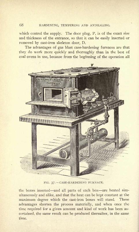
68 HARDENING, TEMPERING AND ANNEALING.
which control the supply. The door plug, P, is of the exact size
and thickness of the entrance, so that it can be easily inserted or
removed by cast-iron skeleton door, D.
The advantages of gas blast case-hardening furnaces are that
they do work more quickly and thoroughly than in the best of
coal ovens in use, because from the beginning of the operation all
FIG. 37. CASE-HARDENING FURNACE.
the boxes inserted and all parts of each box are heated sim-
tillaneously and alike, and that the heat can be kept constant at the
maximum degree which the cast-iron boxes will stand. These
advantages shorten the process materially, and when once the
time required for a given amount and kind of work has been as-
certained, the same result can be produced thereafter, in the same
time.

HEATING STEEL GAS BLAST FURNACES. 69
Heating Machine for Hardening the Edges of Mower Blades.
The machine shown in Fig. 39 is used for hardening the edges
of mower blades, and will operate as fast as the blades can be
dropped into the jaws of the link belt K at I. The jaws are so
formed as to expose only the edge of the blade as far as it is to be
hardened, to the action of the heat, while the body of the blade is
FIG. 38. CASE-HARDENING FURNACE.
protected by the shape of the jaws as they close upon the blade
before entering the heating chamber.
The speed of delivery is regulated by a countershaft with
friction cone, placed above the machine and connected with the
driving pull, H. The burners, B, emit a short focus flame from
both sides and are under the perfect control of the gas valve, G,
and the air valve, A. The jaws of the link belt open as they pass
over the center of the sprocket at I, where the blades are inserted,
closing just as they enter the furnace, and the blades pass through
the heating space at the proper speed, first ascertained by a few
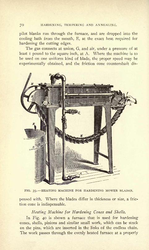
70 HARDENING, TEMPERING AND ANNEALING.
pilot blanks run through the furnace, and are dropped into the
cooling bath from the mouth, E, at the exact heat required for
hardening the cutting edges.
The gas connects at union, G, and air, under a pressure of at
least I pound to the square inch, at A. Where the machine is to
be used on one uniform kind of blade, the proper speed may be
experimentally obtained, and the friction cone countershaft dis-
FIG. 39. HEATING MACHINE FOR HARDENING MOWER BLADES.
pensed with. Where the blades differ in thickness or size, a fric-
tion cone is indispensable.
Heating Machine for Hardening Cones and Shells.
In Fig. 40 is shown a furnace that is used for hardening
cones, shells, pinions and similar small work, which can be stuck
on the pins, which are inserted in the links of the endless chain.
The work passes through the evenly heated furnace at a properly

HEATING STEEL GAS BLAST FURNACES. /I
regulated speed and is discharged from the mouth, F, as fast as it
is fed into the bath, T, without needless exposure to the air. Theheat is under absolute control and the speed of the chain is ad-
justed to it so as to impart the exact temperature to the work re-
quired for proper hardening. When constantly used for the samework the proper speed of the chain is ascertained experimentally
by turning the pull by hand and then speeding the machine ac-
FIG. 40. HEATING MACHINE FOR HARDENING CONES AND
cordingly. When used for a variety of work countershaft with
friction cone pulleys is needed.
Heating Machine with Revolving Trays.
The furnace shown in Fig. 41 is used for tempering needles,
small blades, springs and screws. Its action depends upon heated
air, with temperature so regulated that articles of irregular shapecan be exposed to it long enough to impart the correct color or
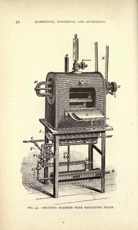
HARDENING, TEMPERING AND ANNEALING.
. 41. HEATING MACHINE WITH REVOLVING TRAYS,

HEATING STEEL GAS BLAST FURNACES. 73
temper to the heavier section, without overheating the thinnest
and lightest part of the same piece. This is accomplished by
regulation of the burner, which is usually divided into three sec-
tions, each under separate control. By these means the injection
of the heat evenly throughout the furnace is easily secured, and
the overheating of either end or the center is prevented. The
burners heat an air chamber connected with the air drum by the
pipe and valve A3, and heated air is distributed in the heating
chamber through perforations in the top of the air chamber under
light pressure, relieved through the vent cock at N. The work is
placed in the pans, DD, which rotate at a speed of twice or thrice
per minute, hanging loosely from rods connected with spokes
around the driving shaft in the center, which receives motion from
the worm gear, IH, connected with power. The door, E, is closed
when furnace is charged with work, and opened for its observation.
When open, the door forms a shelf or rest for the pans. The
thermometer indicates a degree of temperature somewhat different
from the actual heat in the furnace. Once tried for a certain
temper of color, it is a perfect guide for repeating the same re-
sult.
Heating Machine for Small Parts.
The style of heating machine shown in Fig. 42 is used for
heating large quantities of small steel work of uniform size and
weight, evenly and uniformly, to any required degree for hard-
ening, or for annealing the same, automatically. The work Is
placed on the cast-iron link belt, Ci, which revolves entirely
within the heating chamber, N, except where momentarily exposedat entrance, M, to receive the work. The burners, B, penetrate
from each side of the furnace above the link belt, and are perfectly
controlled by the gas valve, G, and the air valve, A.
The belt is supported by sprockets in the heating chamber,
whose shafts revolve on the rolls, D. The belt is moved at re-
quired speed by means of a friction cone which is placed above the
machine and connects with the driving sprockets, F, by the chains,
HH.The weight and size of the work, and the degree of heat which
it requires, determine the speed at which the belt is moved,
and consequently the output. The temperature of the heating
chamber and the speed of the belt being under perfect control,
the output is only limited by the time it takes to heat the work to
the exact degree required.

74 HARDENING, TEMPERING AND ANNEALING.

HEATING STEEL GAS BLAST FURNACES. 75
The cooling part is not a part of the machine, but is shown
merely to illustrate the whole operation. A proper cooling bath
is important. It should be of ample size, and so arranged as to
promptly cool the work without varying materially the tempera-
ture of the oil. Gas connection is made to the union, G, and an
air blast from a positive pressure blower connects at A.
Barrel Healing Machine for Hardening Balls, Saw Teeth, Screws,
Etc.
A type of machine designed for hardening quantities of bicycle
FIG. 43. AUTOMATIC BARREL HEATING AND HARDENING MACHINE.
balls, but which has since been used for hardening detachable
saw teeth, pens, nuts, bolts, screws, and other work not exceed-
ing two and one-half inches in any dimension, is shown in Figs.
43 and 44.
Steel work of any shape is evenly and thoroughly heated to

76 HARDENING, TEMPERING AND ANNEALING.
the exact degree required, regardless of its shape, the thinnest and
thickest parts being discharged at exactly the same temperature.
The machine is capable of heating from 1,500 to 2,000 poundsof steel work per day, the rate of delivery depending upon weight
and shape of the piece.
The cooling bath marked X in the cut is merely a suggestion
and its size depends upon the work to be done, as well as uponthe available water supply for cooling. Its size and construction
FIG. 44. LONGITUDINAL SECTION THROUGH CENTER OP BARRELHEATING MACHINE.
also depend upon the temperature of the water to be used, and
will vary under different circumstances.
Different methods are employed to cool oil baths. One is to
draw the hot oil from the top, running it through pipes immersed
in cold water, and pumping it back to the bottom of the tank
cooled. Another is as illustrated. The tank holding the oil is
shallow and water jacketed, the water being circulated at the rate
required to keep the bath at proper temperature, determined by
reference to a thermometer.
Where the water supply itself is not sufficiently cool, the bath
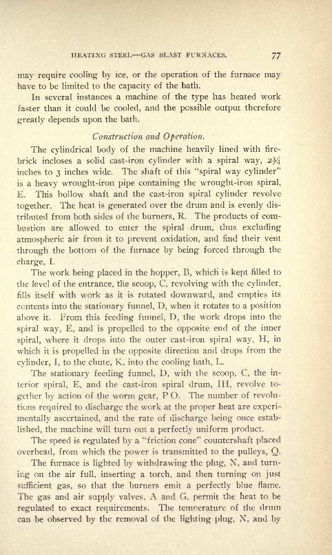
HEATING STEEL GAS BLAST FURNACES. 77
may require cooling by ice, or the operation of the furnace mayhave to be limited to the capacity of the bath.
In several instances a machine of the type has heated work
faster than it could be cooled, and the possible output therefore
greatly depends upon the bath.
Construction and Operation.
The cylindrical body of the machine heavily lined with fire-
brick incloses a solid cast-iron cylinder with a spiral way, 2%inches to 3 inches wide. The shaft of this "spiral way cylinder"
is a heavy wrought-iron pipe containing the wrought-iron spiral,
E. This hollow shaft and the cast-iron spiral cylinder revolve
together. The heat is generated over the drum and is evenly dis-
tributed from both sides of the burners, R. The products of com-
bustion are allowed to enter the spiral drum, thus excluding
atmospheric air from it to prevent oxidation, and find their vent
through the bottom of the furnace by being forced through the
charge, I.
The work being placed in the hopper, B, which is kept filled to
the level of the entrance, the scoop, C, revolving with the cylinder,
fills itself with work as it is rotated downward, and empties its
contents into the stationary funnel, D, when it rotates to a position
above it. From this feeding funnel, D, the work drops into the
spiral way, E, and is propelled to the opposite end of the inner
spiral, where it drops into the outer cast-iron spiral way, H, in
which it is propelled in the opposite direction and drops from the
cylinder, I, to the chute, K, into the cooling bath, L.
The stationary feeding funnel, D, with the scoop, C, the in-
terior spiral, E, and the cast-iron spiral drum, IH, revolve to-
gether by action of the worm gear, P O. The number of revolu-
tions required to discharge the work at the proper heat are experi-
mentally ascertained, and the rate of discharge being once estab-
lished, the machine will turn out a perfectly uniform product.
The speed is regulated by a "friction cone" countershaft placed
overhead, from which the power is transmitted to the pulleys, Q.
The furnace is lighted by withdrawing the plug, N, and turn-
ing on the air full, inserting a torch, and then turning on just
sufficient gas, so that the burners emit a perfectly blue flame.
The gas and air supply valves, A and G, permit the heat to be
regulated to exact requirements. The temperature of the drum
can be observed by the removal of the lighting plug, N, and by

78 HARDENING, TEMPERING AND ANNEALING.
means of the friction cone the time required for heating and de-
livery can be regulated with precision.
It will usually require from 45 minutes to one hour to heat the
spiral ways for hardening. At the expiration of that time the
machine will turn out the work at a regular rate. Where thin
and thick work are put through the machine together, the time of
delivery will be determined by the heaviest article put through,
but the lightest or thinnest will not be overheated unless the tem-
perature is allowed to increase beyond the highest degree required
by hardening.
The main body of the machine is a solid fireclay cylinder in-
closed by a heavy sheet-iron casing. All bearings are ball or
roller bearings, needing but little lubrication. Both heads of the
machine can be removed for the inserting of a new cylinder when
required, the body of the furnace resting independently upon the
table, thus remaining in position if heads are detached.
Heating Machine for Tempering and Coloring Steel.
A machine for tempering and coloring steel work in quantities
with perfect uniformity is shown in Fig. 45. The cut represents
an improved type of machine which has been in satisfactory opera-
tion for several years, for tempering and coloring pens, bicycle
chain link blocks, penholders, saw teeth, screws, buttons, and
other similar work not over two inches in any dimension.
The operation is performed by subjecting the work to the
action of sand or ground flint heated to the proper degree re-
quired for any grade of temper, and a bright, clean and perfectly
uniform temper color is obtained when the work has been properly
prepared for coloring by thorough cleansing.
The capacity of the machine depends upon the size and weight
of the articles, but as a criterion for its efficiency we can say that
we have witnessed bicycle chain blocks and insertable saw teeth
being put through at the rate of 150 pounds per hour.
The work is placed in the hopper, X, containing a small scoop,
which at every revolution deposits a measured quantity into a fun-
nel leading into the heating drum. This drum, contained in the
main body of the machine, is provided with a spiral way which
gradually propels the work to discharge Z.
The spiral partitions are inclosed by a perforated cylinder,
through which sand or flint heated to the proper temperature to
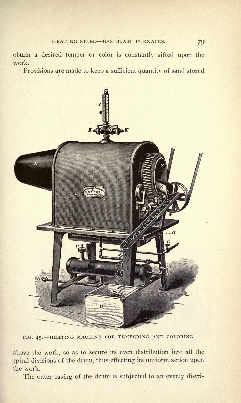
HEATING STEEL GAS BLAST FURNACES. 79
obtain a desired temper or color is constantly sifted upon the
work.
Provisions are made to keep a sufficient quantity of sand stored
FIG. 45. HEATING MACHINE FOR TEMPERING AND COLORING.
above the work, so as to secure its even distribution into all the
spiral divisions of the drum, thus effecting its uniform action upon
the work.
The outer casing of the drum is subjected to an evenly distri-

8o HARDENING, TEMPERING AND ANNEALING.
buted heat, controlled by proper adjustment of the gas valve, Gr
and the air valve, B.
The speed at which the work passes through the spiral drum Is
regulated by a friction cone placed above the machine, and the
temperature by reference to the thermometer, I.
By noting the temperature at which different colors are ob-
FIG. 46. CIRCULAR ANNEALING AND HARDENING FURNACE.

HEATING STEEL GAS BLAST FURNACES. 8 1
tained by a given rate of delivery, the exact conditions of heat
and speed under which a variation of color or temper is obtained
can be readily observed and the perfect uniformity of the output
assured.
Circular Annealing and Hardening Furnace.
The furnace shown in Fig. 46 is used for heating large rims,
rings, discs, dies and other circular steel blocks which do not ex-
ceed 30 inches in diameter and 10 inches in thickness.
The illustration shows a circular block, K, resting upon the fire-
brick supports, H, so placed that they do not in any way obstruct
the flames emitted from the four burners, B. The direction of
the flame is tangential at the proper angle, to secure a rotary or
whirling motion of the flame, and the even distribution of the heat,
-effecting the perfectly even heating of the work. This should be
placed centrally, i. e., equidistant from the inner walls of the
cylindrical casing.
The cover, D, is attached to the cover lift, and held by the
adjustable chains, EE. It is lifted by a toggle joint by pulling the
lever handle inserted in the socket, L, forward, and easily swingsto either side. To replace the firebrick cover, the clasp, M, on
the sheet iron belt which tightly incloses it is unscrewed, and a
new brick lining inserted. The valve, G, admits gas and connects
with the gas supply. A connects with air supply.
Oil Tempering Furnaces.
Furnaces of the type shown in Figs. 47 and 48 are used for
tempering steel work in oil or tallow, and have the advantageover similar apparatus heated by coal that the heat is evenly dis-
tributed and penetrates the bath from all sides, that the temperatureis under perfect control, that no flame can escape from the com-
bustion chamber to ignite the oil or fumes arising from it, and
that the temperature of the oil can be raised to an exceptionally
high degree without risk of flashing. They are made in shapesand sizes to suit, round, square or oblong.
Furnace, Fig. 47, has the burners, B, arranged in-two separate
sections of four, two on each side, each section being under
separate control of the gas and air valves below the distributing
pipes, D and E, respectively.
To heat up the bath, both sets of burners are turned on, and
when the desired temperature is reached, as indicated by the ther-
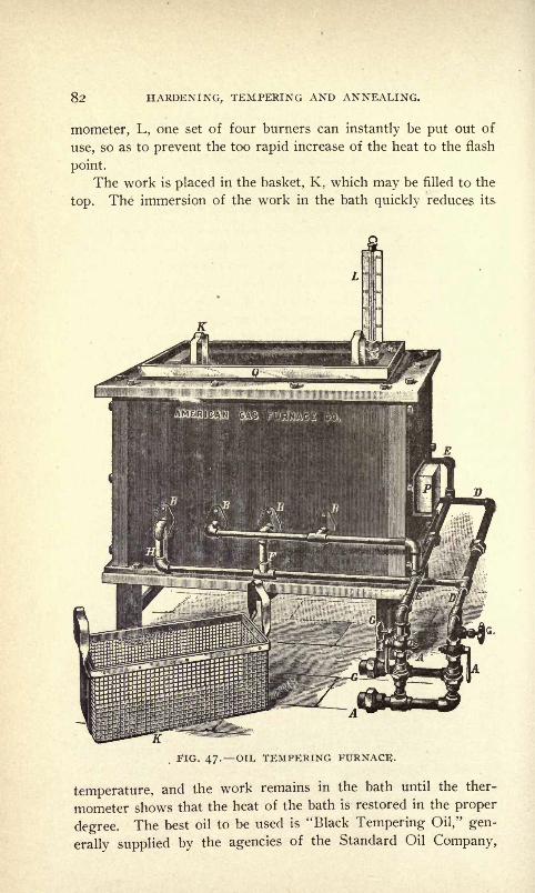
82 HARDENING, TEMPERING AND ANNEALING.
mometer, L, one set of four burners can instantly be put out of
use, so as to prevent the too rapid increase of the heat to the flash
point.
The work is placed in the basket, K, which may be filled to the
top. The immersion of the work in the bath quickly reduces its
,
FIG. 47. OIL TEMPERING FURNACE.
temperature, and the work remains in the bath until the ther-
mometer shows that the heat of the bath is restored in the proper
degree. The best oil to be used is "Black Tempering Oil," gen-
erally supplied by the agencies of the Standard Oil Company,

HEATING STEEL GAS BLAST FURNACES. 83
which can be raised to a temperature of 600 deg. F., and will tem-
per steel from straw color to a light blue. The basket, K, is 18
inches long, 10 inches wide and 8 inches deep.
Oil tempering furnace, Fig. 48, in its construction is similar
FIG. 48. CIRCULAR OIL TEMPERING FURNACE.
to that of a soft metal furnace. The pot is io l/2 inches in diam-
eter, 10 inches deep, and the temperature is regulated by reference
to the thermometer, T, held in place by the clamp, K. The bulb
of the thermometer extends below the middle of the bath, and the
burners are arranged to distribute the heat with perfect evenness
around the pot.
For small work a wire basket is used to contain the articles to
be treated, while larger work is suspended in the bath in any con-
venient way. The temperature being under the perfect control
of the gas and air valves, G and A, the bath is heated until the
thermometer shows the proper heat. When work is submergedin the bath it cools down, and the work remains there until the

4 HARDENING, TEMPERING AND ANNEALING.

HEATING STEEL GAS BLAST FURNACES. 85
temperature rises again to the original degree, when the work
is removed.
Heating Machine for Hardening Chain.
This machine shown in Fig. 49 is one of many heating devices
built for special purposes.
The idea successfully accomplished in this machine is to harden
chains made from sheet steel, which passes from reel Ri first
through the heating space into the cooling bath and is received on
reel R2 perfectly and uniformly hardened.
By the accurate adjustment of burners and speed of travel a
perfect uniformity in hardness of all the links is secured, the
cooling bath is kept at a uniform temperature by proper circula-
tion of the water or oil, which is drawn off the top, and after cool-
ing is pumped back into the bath at the bottom. After the chain
is hardened and wound upon the reel the whole reel is inserted
in an oil tempering furnace to be drawn to the exact temper
required.
Cylindrical Case-Hardening Furnace.
Furnaces of the type shown in Fig. 50 are used for case-hard-
ening car axles of about 6 inches in diameter and not exceeding 8
feet in length.
The axle is inserted in the wrought-iron tube, R, having an
interior diameter of 10 inches. The axle is placed in the exact
center of the retort and the carbon packed tightly around it, after
covering such parts as are not to be case-hardened with fire-clay
or some other non-carbonaceous material. The retort being
packed it is let down into the furnace from a suitable crane over-
head, and the cover, K, put in position as shown, when the furnace
is ready for operation.
The distribution of the heat evenly from the bottom to the topof the retort is effected by two independently controlled sets of
burners;the lower set by the valves G2 and A2, and the upper set
by the valves 63 and A3, while the common supply valves are
Gi and Ai. G stands in each case for gas and A for air.
The proper adjustment having been made on the lower and
upper sets of the burners so as to secure an approximately correct
distribution of the heat, the main gas and air valves are alone
utilized to control the temperature, and the distribution of the
heat properly over the whole length is then effected by the two
vents, one in the bottom indicated by M2, ami one on top in the

86 HARDENING, TEMPERING AND ANNEALING.
FIG. 50. CYLINDRICAL CASE-HARDENING FURNACE FOR CASE
HARDENING CAR AXLES.

HEATING STEEL GAS BLAST FURNACES. O/
center of the cover, K. The top vent being closed entirely, the
heat is driven downward and the products of combustion escape
through the vent, N2. If N2 is closed and cover vent wide open,
the heat is forced upward too rapidly, but by partly closing both
vents, as much as will be found necessary from observation, a
FIG. 51. CYLINDRICAL CASE-HARDENING FURNACE.

88 HARDENING, TEMPERING AND ANNEALING.
perfectly uniform distribution of the heat is effected without a
very close adjustment of the relative strength of the upper and
lower burner tiers.
The regulation of the distribution by the vent holes is espe-
cially important when the temperature is to be raised quicklyand the burners turned on as full as possible in both tiers.
Each row of burners has three burner tips, F, as shown, which
FIG. 52. SOFT METAL FURNACE FOR LEAD HARDENING.
enter the cylinders from four sides at the proper angle to secure
a rotary motion of the flame around the retort without impinging
upon it. The body of the furnace contains three observation holes
closed by the plugs, Li, L2, and L3. The lighting hole is not
visible in cut but is indicated in the rear of the furnace by N2 and
closed by the plug Ni.
Lead Hardening Furnace.
The style of furnace shown in Fig. 52 is used for heating lead
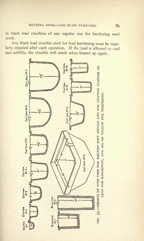
HEATING STEEL GAS BLAST FURNACES. 89
in black lead crucibles of any regular size for hardening steel
work.
Any black lead crucible used for lead hardening must be regu-larly emptied after each operation. If the lead is allowed to cool
and solidify, the crucible will crack when heated up again.

9O HARDENING, TEMPERING AND ANNEALING.
Melting Pots.
Figs. 53 and 54 show charts of pots used for melting soft
metals and for heating cyanide or lead for hardening, and oil or
tallow for tempering.

HEATING STEEL GAS BLAST FURNACES. QI
Cyanide Hardening Furnaces.
The furnace shown in Fig. 55 is of a type used for heating
-steel work in cyanide of potassium for hardening ; they are used
by the leading bank note engravers in the United States for hard-
ening transfer rolls and engraved plates, and by manufacturers
FIG. 55. CYANIDE HARDENING FURNACE FOR CUTTERS,
DIES, ROLLS, ETC.

92 HARDENING, TEMPERING AND ANNEALING.
for hardening cutters, dies, springs, and other steel work requiring
a hardened surface. Their general features are also utilized in
apparatus for heating chemical solution where the escape of

HEATING STEEL GAS BLAST FURNACES. 93
poisonous fumes from the pot or caldron into the room must be
prevented. It contains a cast-iron or steel pot suspended by a
flange with raised edge in the center of the heating chamber.
The two opposite burners, BB, inject the flames into the spacebetween the pot and surrounding firebrick lining, and heat the
pot evenly without coming in direct contact with it. The two
lighting holes in front are closed after the furnace is put in op-
eration, and the products of combustion find their outlet in the pipe,
E, which extends upward in the rear and enters the elbow on the
sheet-iron pipe, S, passing the draft hole near the top of the hood,H. The heat from the combustion chamber is thus injected into
the draft pipe, S, and a positive draft is created which carries off
the fumes as they rise from the pot. Thus the poisonous fumesare carried off into the chimney, and with ordinary care none
escapes into the room. Gas and air are indicated at G and A.
Regular Sizes of Muffles.
The annexed chart, Fig. 56, shows the regular sizes of muffles
which are on the market. The number of the muffle correspondsto the number of the furnace, so that orders .for the muffles can
be given by the furnace number, or a furnace ordered by the num-ber of the muffle.
The dimensions of muffles are their interior measurement.
Muffle Furnace.
The muffle furnace shown in Fig. 57 is typical of large sizes
for heavy kinds of work requiring high heat. It is entirely en-
cased in cast-iron framework firmly bolted together, with heavy
linings and carefully trimmed and fitted fireclay sections. The
casing is filled in above and around the arch with non-conductingmaterial to lessen radiation, and the muffle bottom is protected
by extra supports, as in oven furnaces, to prevent sagging under
weight.
Tough Steel and Hard Steel The Difference.
Although few mechanics seem to be aware of it, there is con-
siderable difference between steel which is hard and steel which is
both hard and tough, i. e., when a tool has been hardened and
tempered to the degree thought best for the work which it is to
perform and the edge does not stand up, but, instead, crumbles
away, the steel is hard but is not tough and was heated wrongly in

94 HARDENING, TEMPERING AND ANNEALING.
hardening, or was not quenched right. On the contrary, when a
tool has been heated properly and hardened and tempered as it
should be, it can be very hard and the edge will hold because for
given degrees of hardness the same degree of toughness has been
imparted during the heating and hardening processes.
N
FIG. 57. MUFFLB FURNACE.

CHAPTER IV.
THE HARDENING OF STEEL HARDENING IN WATER, BRINE, OIL,
AND SOLUTIONS SPECIAL PROCESSES FOR SPECIAL STEEL.
Judgment and Carefulness in Hardening.
As a great deal depends on the judgment and carefulness of
the man who does the hardening in a shop, in all large manufac-
turing establishments the job of doing all the hardening should
be given to one man. On this man's efficiency and judgment will
depend the increasing or the reducing of the cost account, as one
piece of steel which has been hardened properly will accomplish
many times as much as a piece which has been hardened imper-
fectly. The manner in which the operator puts the steel into the
quenching liquid will be responsible more than anything else, for
having the pieces come out hard and free from cracks or deformi-
ties. Work with deep recesses will often have to go into the water
with the recessed part first, or vise versa, according to the shape
and location of the same.
When hardening large pieces which are worked out in the
center, a stream of water striking against them is often abso-
lutely necessary. There are some grades of steel which will give
the best results if they are removed from the water as soon as the
vibration has ceased and laid aside until cold. Experience, skill,
and good sound judgment are necessary to do good hardening.
Successful Hardening.
In almost every establishment where any large amount of steel
is hardened, some one man will be found who is considered an
expert in the art. When such men really possess the required
judgment and skill they are careful in the heating and quenching,and good results are attained. Very often, however, the man whois considered an authority on the subject, possesses very little real
knowledge, but instead, through pure "gall" and "nerve," takes
chances and either comes out on top or manages to cover up his
mistakes. Beware of such men; they are responsible for more
bad work in the shop than any others.
First and foremost, the effect of annealing on steel which is
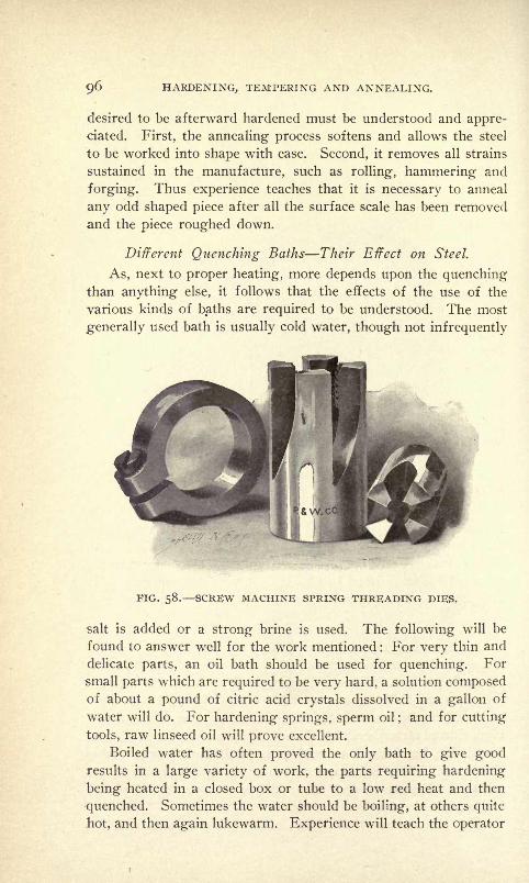
96 HARDENING, TEMPERING AND ANNEALING.
desired to be afterward hardened must be understood and appre-
ciated. First, the annealing process softens and allows the steel
to be worked into shape with ease. Second, it removes all strains
sustained in the manufacture, such as rolling, hammering and
forging. Thus experience teaches that it is necessary to anneal
any odd shaped piece after all the surface scale has been removed
and the piece roughed down.
Different Quenching Baths Their Effect on Steel.
As, next to proper heating, more depends upon the quenchingthan anything else, it follows that the effects of the use of the
various kinds of baths are required to be understood. The most
generally used bath is usually cold water, though not infrequently
iBP^^i xffi|fep
FIG. 58. SCREW MACHINE SPRING THREADING DIES.
salt is added or a strong brine is used. The following will be
found to answer well for the work mentioned : For very thin and
delicate parts, an oil bath should be used for quenching. For
small parts which are required to be very hard, a solution composedof about a pound of citric acid crystals dissolved in a gallon of
water will do. For hardening springs, sperm oil;and for cutting
tools, raw linseed oil will prove excellent.
Boiled water has often proved the only bath to give goodresults in a large variety of work, the parts requiring hardening
being heated in a closed box or tube to a low red heat and then
quenched. Sometimes the water should be boiling, at others quite
hot, and then again lukewarm. Experience will teach the operator
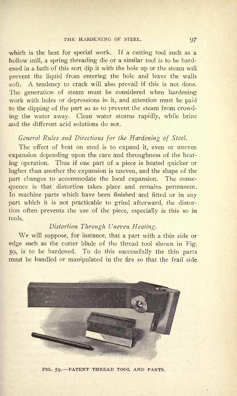
THE HARDENING OF STEEL. 97
which is the best for special work. If a cutting tool such as a
hollow mill, a spring threading die or a similar tool is to be hard-
ened in a bath of this sort dip it with the hole up or the steam will
prevent the liquid from entering the hole and leave the walls
soft. A tendency to crack will also prevail if this is not done.
The generation of steam must be considered when hardening
work with holes or depressions in it, and attention must be paid
to the dipping of the part so as to prevent the steam from crowd-
ing the water away. Clean water steams rapidly, while brine
and the different acid solutions do not.
General Rules and Directions for the Hardening of Steel.
The effect of heat on steel is to expand it, even or uneven
expansion depending upon the care and throughness of the heat-
ing operation. Thus if one part of a piece is heated quicker or
higher than another the expansion is uneven, and the shape of the
part changes to accommodate the local expansion. The conse-
quence is that distortion takes place and remains permanent.In machine parts which have been finished and fitted or in any
part which it is not practicable to grind afterward, the distor-
tion often prevents the use of the piece, especially is this so in
tools.
Distortion Through Uneven Heating.
We will suppose, for instance, that a part with a thin side or
edge such as the cutter blade of the thread tool shown in Fig.
59, is to be hardened. To do this successfully the thin parts
must be handled or manipulated in the fire so that the frail side
FIG. 59. PATENT THREAD TOOI, AND PARTS.
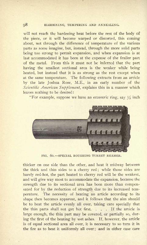
98 HARDENING,, TEMPERING AND ANNEALING.
will not reach the hardening heat before the rest of the body of
the piece, or it will become warped or distorted, this coming
about, not through the difference of temperature of the various
parts as some imagine, but, instead, through the more solid parts
being too strong to permit expansion, and when expansion is at
last accommodated it has been at the expense of the frailer part
of the metal. From this it must not be inferred that the part
having the smallest sectional area is the weaker while being
heated, but instead that it is as strong as the rest except when
at the same temperature. The following extracts from an article
by the late Joshua Rose, M.E., in an early number of the
Scientific American Supplement, explains this in a manner which
leaves nothing to be desired :
"For example, suppose we have an eccentric ring, say y2 inch
FIG. 60. SPECIAI, ROUGHING TURRET REAMER.
thicker on one side than the other, and heat it midway between
the thick and thin sides to a cherry red;
while those sides are
barely red-hot, the part heated to cherry red will be the weakest,
and will give way most to accommodate the expansion, because the
strength due to its sectional area has been more than compen-sated for by the reduction of strength due to its increased tem-
perature. The necessity of heating an article according to its
shape then becomes apparent, and it follows that the aim should
be to heat the article evenly all over, taking care specially that
the thin parts shall not get hot first. ... If the article is
large enough, the thin part may be covered, or partially so, dur-
ing the first of the heating by wet ashes. If, however, the article
is of equal sectional area all over, it is necessary to so turn it in
the fire as to heat it uniformly all over;and in either case care
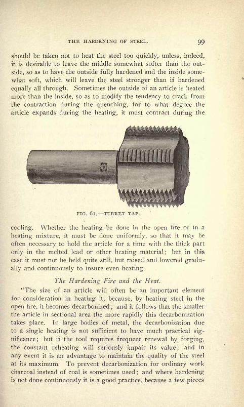
THE HARDENING OF STEEL. 99
should be taken not to heat the steel too quickly, unless, indeed,
it is desirable to leave the middle somewhat softer than the out-
side, so as to have the outside fully hardened and the inside some-
what soft, which will leave the steel stronger than if hardened
equally all through. Sometimes the outside of an article is heated
more than the inside, so as to modify the tendency to crack from
the contraction during the quenching, for to what degree the
article expands during the heating, it must contract during the
FIG. 6l. TURRET TAP.
cooling. Whether the heating be done in the open fire or in a
heating mixture, it must be done uniformly, so that it may be
often necessary to hold the article for a time with the thick part
only in the melted lead or other heating material;
but in this
case it must not be held quite still, but raised and lowered gradu-
ally and continuously to insure even heating.
The Hardening Fire and the Heat.
"The size of an article will often be an important element
for consideration in heating it, because, by heating steel in the
open fire, it becomes decarbonized;and it follows that the smaller
the article in sectional area the more rapidly this decarbonization
takes place. In large bodies of metal, the decarbonization due
to a single heating is not sufficient to have much practical sig-
nificance;
but if the tool requires frequent renewal by forging,
the constant reheating will seriously impair its value;
and in
any event it is an advantage to maintain the quality of the steel
at its maximum. To prevent decarbonization for ordinary work
charcoal instead of coal is sometimes used;and where hardening
is not done continuously it is a good practice, because a few pieces
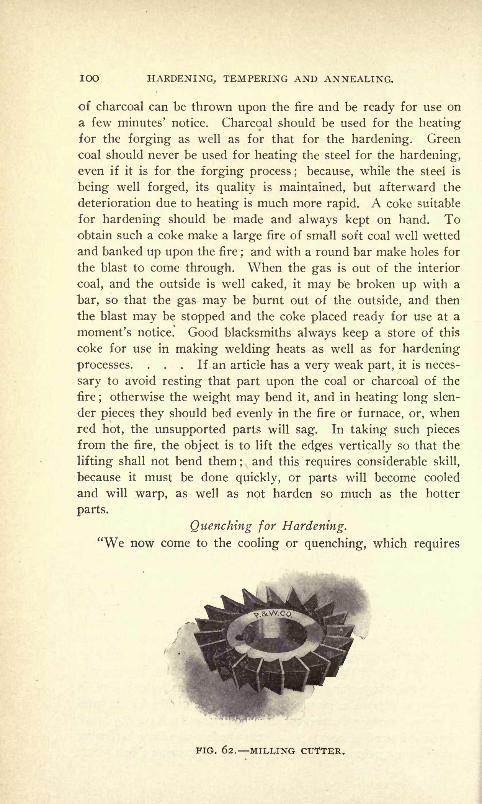
IOO HARDENING, TEMPERING AND ANNEALING.
of charcoal can be thrown upon the fire and be ready for use on
a few minutes' notice. Charcoal should be used for the heatingfor the forging as well as for that for the hardening. Green
coal should never be used for heating the steel for the hardening,even if it is for the forging process ; because, while the steel is
being well forged, its quality is maintained, but afterward the
deterioration due to heating is much more rapid. A coke suitable
for hardening should be made and always kept on hand. Toobtain such a coke make a large fire of small soft coal well wetted
and banked up upon the fire ;and with a round bar make holes for
the blast to come through. When the gas is out of the interior
coal, and the outside is well caked, it may be broken up with a
bar, so that the gas may be burnt out of the outside, and then
the blast may be stopped and the coke placed ready for use at a
moment's notice. Good blacksmiths always keep a store of this
coke for use in making welding heats as well as for hardening
processes. . . . If an article has a very weak part, it is neces-
sary to avoid resting that part upon the coal or charcoal of the
fire;otherwise the weight may bend it, and in heating long slen-
der pieces they should bed evenly in the fire or furnace, or, whenred hot, the unsupported parts will sag. In taking such pieces
from the fire, the object is to lift the edges vertically so that the
lifting shall not bend them; and this requires considerable skill,
because it must be done quickly, or parts will become cooled
and will warp, as well as not harden so much as the hotter
parts.
Quenching for Hardening.
"We now come to the cooling or quenching, which requires
FIG. 62. MILLING CUTTER.
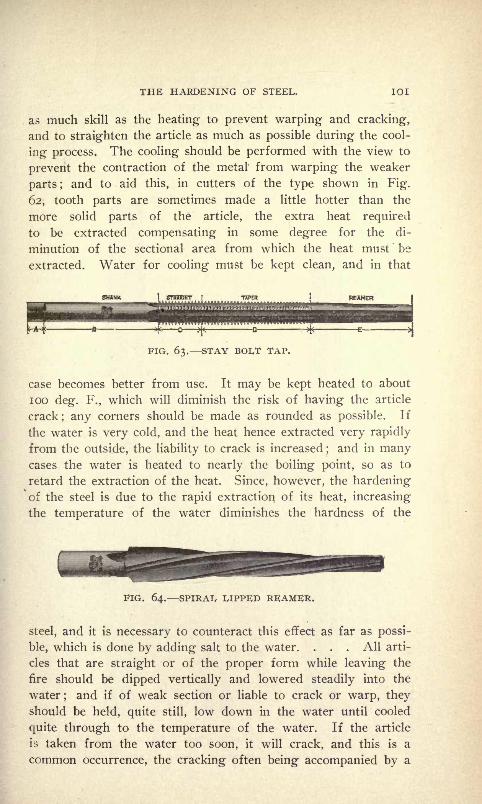
THE HARDENING OF STEEL. 101
as much skill as the heating to prevent warping and cracking,
and to straighten the article as much as possible during the cool-
ing process. The cooling should be performed with the view to
prevent the contraction of the metal from warping the weaker
parts ;and to aid this, in cutters of the type shown in Fig.
62, tooth parts are sometimes made a little hotter than the
more solid parts of the article, the extra heat required
to be extracted compensating in some degree for the di-
minution of the sectional area from which the heat must'
be
extracted. Water for cooling must be kept clean, and in that
PIG. 63. STAY BOI/T TAP.
case becomes better from use. It may be kept heated to about
100 deg. F., which will diminish the risk of having the article
crack; any corners should be made as rounded as possible. If
the water is very cold, and the heat hence extracted very rapidly
from the outside, the liability to crack is increased;and in many
cases the water is heated to nearly the boiling point, so as to
retard the extraction of the heat. Since, however, the hardeningof the steel is due to the rapid extraction of its heat, increasing
the temperature of the water diminishes the hardness of the
FIG. 64. SPIRAL LIPPED REAMER.
steel, and it is necessary to counteract this effect as far as possi-
ble, which is done by adding salt to the water. . . . All arti-
cles that are straight or of the proper form while leaving the
fire should be dipped vertically and lowered steadily into the
water;and if of weak section or liable to crack or warp, they
should be held, quite still, low down in the water until cooled
quite through to the temperature of the water. If the article
is taken from the water too soon, it will crack, and this is a
common occurrence, the cracking often being accompanied by a

102 HARDENING, TEMPERING AND ANNEALING.
sharp, audible "click." Pieces of blade form should be dipped
edgeways, the length of the article lying horizontally and the
article lowered vertically and held quite still, because, by mov-
ing it laterally, the advancing side becomes cooled the quickest,
and warping and cracking may ensue. Straight cylindrical pieces
Sellers Hob. Short Shank Hob I,ong Taper Die Tapfor Sizing Dies. for Cutting Solid Dies.
FIG. 65. HOBS OR MASTER TAPS.

THE HARDENING OF STEEL. 1 03
are dipped endwise and vertically. When, however, the dipping
process is performed with a view to leave a sufficient heat in the
body of the article to draw to a lower temper the part dipped,
the method of proceeding is slightly varied."
The Hardening of Long Slender Tools.
In order to harden long slender tools, such as stay-bolt taps,
"hob" taps and long, taper die taps, for instance, so as to not
require subsequent straightening or grinding, care is necessary in
the machining as well as the hardening operations. It is not de-
sirable to use the highest carbon steel when a large tool is to be
made if the hardening method given below is to be used.
Have the stock for the tool about y inch larger than the
finish diameter and rough down to within 1-16 inch of size. Then
pack in an iron box in powdered charcoal and reheat, heating
to a red and being sure to heat evenly and slowly.* This will re-
move all strains which may have taken place in the steel during
the manufacture. The slower the steel cools the better will be
the results in the hardening, as it may be heated to a lower heat
which will have a tendency to refine it.
Sometimes when the rough-down blanks for long tools have
been annealed by the method described above, upon taking them
from the annealing box some will be found to have sprung. Whenthis occurs do not attempt to straighten while cool, but instead,
if possible, turn the bulge out. If this cannot be done, heat to a
cherry red and straighten while hot and re-anneal. After finish-
ing, test the tool for trueness, and then harden as follows :
Have a box large enough to allow the tools to stand upright
and to leave lots of space for packing at the top, bottom and sides.
Pack the packing material around tightly, put the lid on the box
and heat thoroughly through, testing for heat with test rods, and
when the proper heat is obtained hold it for a few hours, then
remove the box and draw the tools carefully from the pack with
a pair of tongs and quench in a bath of raw linseed oil which
may be kept at a sufficient low temperature by some simple cool-
ing arrangement.
When dipping the heated tools quench straight down into the
center of the oil and move vertically until a black appears, when
they may be moved to the edsfe of the bath tank. In an oil bath
the contents should be po-itated so that the oil will circulate and
flow toward the center, thus keeping the vapor generated by con-

IO4 HARDENING, TEMPERING AND ANNEALING.
tact of the heated steel and oil away from the work. By doing*
this there will be no soft spots in the wcrk when hardened.
Hardening Small Parts and Long Thin Parts.
When a large number of very small parts, such as cutter
blades of the type shown in Fig. 66, are to be hardened they
FIG. 66. PATENT SQUARE THREADING TOOL.
should be packed in closed iron boxes, and the box heated.
When all the parts have reached the proper heat, they should be
dumped into the quenching bath, of either oil or water, as the
nature of the work may require. Another way by which small
parts may be heated uniform is by means of a lead bath. Keep
FIG. 67. COMBINED DRILL AND COUNTERSINK.
the lead at the proper heat and cover the top with powdered char-
coal and coke.
Very small tools, such as small piercing punches, etc., should
be hardened in an oil bath or in luke warm water, as if cold
water is used they will cool too quickly and come out of the bath
cracked or so brittle as to be useless. Never heat a piece of steel
for hardening hot enough to ra : se scale on it; even when it is

THE HARDENING OF STEEL. 105
a very large piece this can be overcome by heating very slowly
in a packing box. When steel has been heated too hot and then
quenched, the grain is rendered coarse and brittle, and, althoughit may be drawn to the desired temper, it will break quicker than
FIG. 68. TWIST DRILL.
a piece which has been hardened at a very low heat and not tem-
pered at all, although the piece which was heated too hot and
hardened and drawn will be softer than the other piece.
When hardening long, flat or round objects they should be
FIG. 69. TWIST DRILL.
dipped endwise, holding them perpendicular with the surface of
the bath. When this is done the articles will come out perfectly
straight, or at least very little sprung. When dipped otherwise
such tools will warp. When dipping a half-round tool dip it with
FIG. 70. TURRET REAMER FOR FINISHING.
the half-round side at an angle of about twenty degrees with the
surface of the water and it will come out either almost straight,
or straight.

IO6 HARDENING, TEMPERING AND ANNEALING.
Hardening in Solutions.
In order to harden a large number of steel tools or pieces so
that uniform hardness and temper will be attained, and so that
the steel will come out of the process white and clean, as is often
required, the following process may be adopted: First, in the
heating of the steel, a solution which will project it from the
fire and another to chill it quickly are necessary. This last
solution will also give the desired clean white appearance to the
steel. The receipt for this first solution is, equal quantities of sal-
soda and borax in water containing one ounce of cyanide of
potassium to the gallon. For the second solution, a strong brine
made of salt and water, and about the same amount of cyanideas salt, will do. Have the water hot and add about two ounces
of sulphuric acid to each gallon of water used;when mixed, put
away in a cool place and keep well covered.
To use the solutions proceed as follows: Fill all holes near
the edge of the steel with fireclay, then dip into the first solution
and place the steel immediately on the fire while wet. Heat
slowly and carefully and be sure not to heat any one portion of
the work faster than another, as the slower the heat the more
uniform its distribution in the piece. When the proper tempera-ture has been reached, which should be a clear bright red, dip
the work straight down into the hardening solution; when it
has cooled, remove from the bath, and work of silvery whiteness
and uniform hardness will be the result. When heating longslender pieces in this solution, dip them endwise, and do not shake
about, but instead, revolve, if possible, rapidly.
Heating in Hot Lead for Hardening.
There is a large class of work which can be best heated for
hardening in red-hot lead. It is a very rapid and satisfactory
method for such tools as small counter-bores, reamers, shank,
mills, knurls and parts such as bicycle cones, balls, cups, and sew-
ing machine and typewriter parts. What makes the lead par-
ticularly valuable for heating such parts is that a uniform heat
can be applied without danger of burning or scaling the inside be-
fore the center is heated.
When heating in lead a graphite crucible placed so that a
uniform heat will be maintained beneath and around the pot will
prove the best. As to the lead to use, care must be taken to get
a brand with as little sulphur in it as possible. Never use scrap

THE HARDENING OF STEEL. 107
lead, as it will ruin the steel. Chemically pure lead should alwaysbe used.
There are a great many compounds in use to prevent the lead
from sticking to the work. One of the best is the following : One
pound of powdered cyanide dissolved in one gallon of boiling
FIG. 71. HEAVY KNURLS.
water;allow to cool, and then dip the articles to be heated in the
solution; remove and allow to dry thoroughly before puttingthem into the lead. Moisture will make the lead fly.
Small articles of an even size and thickness throughout can
be put into the lead cold, while irregular pieces must be heated
FIG. 72. DOUBLE KNURLING TOOL.
nearly red before putting into the lead in order to prevent un-
equal expansion.
By keeping the surface of the lead covered with broken char-
coal, drops will be prevented from forming. After the heatinghas been concluded empty the crucible.
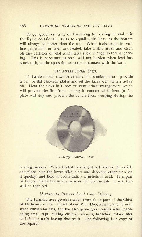
IO8 HARDENING, TEMPERING AND ANNEALING.
To get good results when hardening by heating in lead, stir
the liquid occasionally so as to equalize the heat, as the bottom
will always be hotter than the top. When tools or parts with
fine projections or teeth are heated, take a stiff brush and clean
off any particles of lead which may stick in them before quench-
ing. This is necessary as steel will not harden when lead has
stuck to it, as the spots do not come in contact with the bath.
Hardening Metal Saws.
To harden metal saws or articles of a similar nature, providea pair of flat cast-iron plates and oil the faces well with a heavyoil. Heat the saws in a box or some other arrangement which
will prevent the fire from coming in contact with them (a flat
plate will do) and prevent the article from warping during the
FIG. 73. METAL SAW.
heating process. When heated to a bright red remove the article
and place it on the lower oiled plate and drop the other plate on
it quickly, and hold it down until the article is cold. If a pair
of hinged plates are used one man can do the job; if not, two
will be required.
Mixture to Prevent Lead from Sticking.
The formula here given is taken from the report of the Chief
of Ordnance of the United States War Department, and is used
when hardening files, and has also given good results when hard-
ening small taps, milling cutters, reamers, broaches, rotary files
and similar tools having fine teeth. The following is a copy of
the report:

THE HARDENING OF STEEL. 109
"Before hardening, the files are treated with a mixture of salt
and carbonaceous materials to protect the teeth from decarboniza-
tion and oxidation. The kinds and proportions of the ingredientsare given in the following table :
"Pulverized and charred leather I pound."Fine family flour ij^ pounds."Fine table salt 2 pounds.
"The charcoal made from charred leather should be triturated
until fine enough to pass through a No. 45 sieve.
"The three ingredients are thoroughly mixed and incorporated
while in a dry state and water is then added slowly to prevent
lumps, until paste formed has the consistency of ordinary varnish.
When ready the paste is applied to the file with a brush, care
being taken to have the teeth well filled with the mixture. The
surplus paste is then wiped off the file by the brush and the file
is placed on end before a slow fire to dry. If dried too quickly,
the paste will crack or blister; if not dried enough, the remain-
ing moisture will be transformed into steam when dipped into
the heated lead bath and cause an ebullition or sputtering of the
lead, throwing out minute globules of the latter which may en-
danger the eyes of the operator. The fusing of the paste uponthe surface of the file indicates the proper heat at which the file
should be hardened."
Hardening Long Taper Reamers.
The hardening of long taper reamers of small diameter, so
as to prevent them from coming through curved or twisted, is one
of the most difficult operations for the hardener, and we can only
advise the necessary precautions used by those who succeed with
such work. The steel should be annealed a second time before
the finishing cut is taken, by heating slowly in a low fire by pack-
ing it in an iron box or tube with powdered charcoal, fine sand,
or clean ashes;then finished. The heating for hardening should
be done in the same manner as the re-annealing. When the box
and reamer have been heated thoroughly to a bright cherry red the
reamers should be carefully drawn out endwise, so as to prevent
the possibility of bending while hot; and immediately quenched
vertically in an oil bath. Any variation from a vertical position
while dipping is liable to warp the work, through one side cool-
IIO . HARDENING, TEMPERING AND ANNEALING.
ing faster than the other. In drawing temper, care should be
taken to heat evenly on all sides, so as to bring them to the same
straw color, brown or light blue, according to whatever use the
tool is to be put. Long delicate reamers should always be groundto size after the hardening and tempering operations.
The Use of Clay in Hardening.
Very often in die and tool work it is desired that a piece with
a hole in the center should be hard around the outside and soft
around the hole, or a punch is required to be hard at both ends
and soft in the center. To accomplish these results with ease
use clay in the following manner: When the stock around the
hole is to be left soft and the outer edges of the piece hardened,
fill the hole with clay and pad it at both sides, then heat the piece
and plunge it into the water. When cool, remove the clay and
the stock around the hole will be found to be soft while the edges
will be as hard as required. To harden both ends of the punchand leave the center soft, put a bandage of clay around the center,
or desired soft portion, about ^4 of an inch thick and bind it
with a piece of thin sheet metal. Heat and quench, and the de-
sired result will be accomplished.
When hardening dies or other press tools in which there are
holes near the edges of the work, fill the holes with clay before
heating and the tendency to crack will be overcome. When the
holes are not filled with clay (when the steel is quenched) steam
generates in the holes and cracks start, or excessive warping oc-
curs, due to the fact that the steam does not escape fast enoughand the contracting of the metal is unequal.
Special Instructions for, Hardening and Tempering.
Often when tool steel is brought, special instructions will be
given as to the method of hardening and tempering it. Some-
times these instructions are followed out and oftener they are
not. Now in all cases when such instructions are given, don't
forget to go by them, otherwise do not buy that brand of steel,
but instead secure a brand which you can harden as you think
best. There are various brands of steel on the market which are
used for a number of special purposes and which possess qualities
which other brands do not (in regard to cutting at rMgh speeds,
removing large amounts of stock, etc.) which require hardening
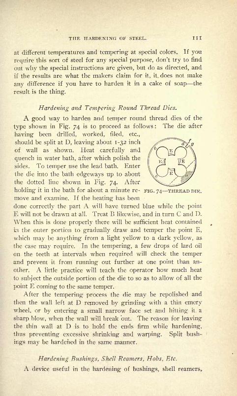
THE HARDENING OF STEEL. Ill
at different temperatures and tempering at special colors. If you
require this sort of steel for any special purpose, don't try to find
out why the special instructions are given, but do as directed, and
if the results are what the makers claim for it, it. does not make
any difference if you have to harden it in a cake of soap the
result is the thing.
Hardening and Tempering Round Thread Dies.
A good way to harden and temper round thread dies of the
type shown in Fig. 74 is to proceed as follows : The die after
having been drilled, worked, filed, etc.,
should be split at D, leaving about 1-32 inch
of wall as shown. Heat carefully and
quench in water bath, after which polish the
sides. To temper use the lead bath. Enter
the die into the bath edgeways up to about
the dotted line shown in Fig. 74. After
holding it in the bath for about a minute re- FIG. 74 THREAD DIE;.
move and examine. If the heating has been
done correctly the part A will have turned blue while the point
E will not be drawn at all. Treat B likewise, and in turn C and D.
When this is done properly there will be sufficient heat contained
in the outer portion to gradually draw and temper the point E,
which may be anything from a light yellow to a dark yellow, as
the case may require. In the tempering, a few drops of lard oil
on the teeth at intervals when required will check the temper
and prevent it from running out further at one point than an-
other. A little practice will teach the operator how much heat
to subject the outside portion of the die to so as to allow of all the
point E coming to the same temper.After the tempering process the die may be repolished and
then the wall left at D removed by grinding with a thin emerywheel, or by entering a small narrow face set and hitting it. a
sharp blow, when the wall will break but. The reason for leaving
the thin wall at D is to hold the ends firm while hardening,
thus preventing excessive shrinking and warping. Split bush-
ings may be hardened in the same manner.
Hardening Bushings, Shell Reamers, Hobs, Etc.
A device useful in the hardening of bushings, shell reamers,

112 HARDENING, TEMPERING AND ANNEALING.
<&'
FIG. 75. USEFULHARDENING DEVICE.
hobs, etc., is shown in Fig. 75, and consists
of a piece of drill rod, R, threaded about an
inch longer than the length of the article to
be hardened, and nut and washer located as
shown. The dotted lines show the work to
be hardened, AAAA, asbestos washers, BB,common iron washers, the whole being held
together between the two nuts. Heat the
entire arrangement to the proper tempera-ture and quench in water in the usual man-ner. By using a device of this sort an up-ward flow of water through the article is
prevented, as is the consequent sudden chill,
thus eliminating to a certain extent tfhe tend-
ency to warp or crack. In such tools in
which the outside only is desired to be hard-
ened, the method is an excellent one, as the
inside will remain comparatively soft, unless
very thin, when it will harden clear through.
Hardening and Tempering Collet Spring Chucks.
The following kink we have found very handy when makingcollet spring chucks of the shape shown in Fig. 76. After finish-
ing them in the lathe, leaving, of
course, enough stock to lap and
grind to a finish, face them on an
arbor and saw the spring slots as
shown; that is, at the end of each
slot, as shown at T and V. In-
stead of cutting completely throughat this point, leave a very thin wall
about y% inch long at the end of
the cuts. Then harden and temper the chucks as desired, and
after lapping the inside to size, place on an arbor and grind the
tapers as required; then take a small, narrow broach and by
entering it into the slots and hitting it a sharp blow with a ham-
mer the thin wall will break through. This kink I have used
to the best advantage in shops which had no grinding facilities.
When proceeding as aforesaid it was possible to finish the outside
and taper to size before hardening without the possibility of the
chucks running out to any noticeable extent. Of course for
FIG. 76. SMALL COLLETSPRING CHUCK.

THE HARDENING OF STEEL. 113
work of the utmost accuracy this method would not do. But
then again work of the utmost accuracy is not accomplished in
shops where the tool facilities are not up to date.
The Taylor-White Process for Treating Steel.
In the September, 1901, number of the Journal of the Franklin
Institute was published a paper by Charles Day upon the Taylor-
White process for treating tool steel, and the results obtained
with steel so treated, at the works of the Link Belt Engineering
Company, Philadelphia, Pa. When this process was first an-
nounced facts were given and quoted reports of tests made at the
works of the Bethlehem Steel Company, Bethlehem, Pa., where
the process was developed by Messrs. Taylor and White. The
paper by Mr. Day gives information upon air hardening steels in
general before reverting to the subject of steel treated by the
Taylor-White process.
Mr. Day says that air-hardening steels have unquestionably
replaced the carbon variety for roughing work, the efficiency of
the former ranging from one and one-half to twice that of the
latter. This gain is because air-hardening steels hold their cut-
ting edge at much higher temperatures than carbon steels and
consequently can be worked at proportionately greater cutting
speeds. The usual method of hardening air-hardening steels is
well known, manufacturers usually placing a great stress on the
fact that the tool must be heated over a cherry red, otherwise it
will be burned and so ruined. The object of Messrs. Taylor and
White was to obtain some exact knowledge on this matter, and
extensive experiments were conducted in the belief that a tool
steel could be produced to give still better results than those
already obtained.
The new process depends upon the fact that although both
carbon and air-hardening steels deteriorate rapidly when the tem-
perature rises above a cherry red, there are some chemical com-
positions that may be used for air-hardening steels which are
much improved as cutting tools if they are raised to a higher
temperature in the hardening process. Their maximum efficiency
is reached when the steel is heated to a point where it crumbles
when tapped with a rod. The point to which air-hardening steel
was formerly heated in the process of hardening is between 1,500
and i,600 deg. F., and is called the breaking-down point. Steel
liaving the new treatment is heated to 2,000 deg. F. The com-

114 HARDENING, TEMPERING AND ANNEALING.
position found to give the best results consists of an air-harden-
ing steel containing about i per cent of chromium and 4 per cent
of tungsten ;while for very hard metals, such as the chilled scale
on cast-iron, etc., 3 per cent of chromium and 6 or more per cent
of tungsten are good. The variation in carbon seems to matter
but little, steel varying from 85 to 200 points giving equally goodresults.
The tool is cooled rapidly from the "high heat" (2,000 de-
grees) to a point below the breaking-down temperature, in a lead
bath, and then slowly in the air, or lime, etc., as the case may be.
It is essential that at no time the temperature should rise, as in
such a case the tool would be seriously impaired. After the
steel has cooled off, its efficiency is found to be further increased
by subjecting it to what is termed the "low heat" for about ten
minutes; this temperature ranging from 700 deg. to 1,240 deg.
F. After cooling from the "low heat" the tool is ready for use.
It is not essential to anneal the steel when reforging and the tools
can be worked with comparative ease.
In the operation of the Taylor-White process apparatus is
employed by means of which temperature can be controlled within
very narrow limits, which accounts for the uniformity of results
obtained with the tools treated by this process.
About 97 per cent of the material worked upon at the shops of
the Link Belt Engineering Company is cast-iron. In order to
make a rough test on cast-iron one tool was obtained from Bethle-
hem and put to work on a 7-foot boring mill turning the inside
of a cast-iron ring. The time required to do this work with their
old tools had been determined many times in setting piece rates,
and was about fourteen hours. With the Taylor-White tool the
time was reduced to three and one-half hours, and a gain of 75
per cent made. While steel used heretofore was not the best ob-
tainable, and was probably not worked to its highest efficiency,
there was, nevertheless, a large saving due to the new steel.
Some interesting data was also obtained from an order of
rope sheaves, the time required on similar work having been tabu-
lated for several years. The average time required to machine
thirteen sheaves with the old tools was nine and one-half hours ;
the same for sixteen similar sheaves, the roughing being done by
Taylor-White tools, was five hours and five minutes, or a saving
of 46^2 per cent.
Assuming, however, the time for setting up, forming, boring
THE HARDENING OF STEEL. 115
and polishing the same when the sheaves were finished with old
tools as with the treated tools, since the latter are not suitable for
cutting finishing cuts, the time for roughing would have been
7.85 hours and a saving of 56.3 per cent was made in operations
where it was possible to use treated tools.
In order to obtain some data with regard to pressure on the
points of tools for given depth of cuts, feed, etc., and at the
same time to show the effect of the treatment, a cast-iron ring
six and one-half feet in diameter was bolted to the table of a
seven-foot mill. The first tool used was one treated for hard
material. It cut 106 pounds of metal in 10 minutes, and when
removed was in perfect condition. A "Mushet" tool under the
same condition lasted but one minute, and removed 5^2 poundsof metal. The actual pressure against the tool in each case ex-
ceeded 3^4 tons, while the pressure per square inch with another
self-hardening tool was 143,000 pounds.
Eighteen months ago a 50 horse power engine supplied the
power for about 40 machine tools in the Link Belt Engineering
Company's works, and also run the pattern shop and grinding
room. The actual horse power developed had been found to
average 45. Of this 27 horse power was consumed by the shaft-
ing, leaving but 18 horse power for actual work. After the new
tools were in general use and the machine pushed to obtain the de-
sired results, it became apparent that the power was absolutely in-
adequate; indicator cards from the engine frequently showed
an overload of 60 per cent, and at this point it was found essen-
tial to put motors on some of the larger tools.
The following particulars about the process have been fur-
nished by the Bethlehem Steel Company :
"The practical speeds at which these tools will run has been
found to be from two to four times that of any steels which wehave experimented with, and we have endeavored to obtain the
best in the market.
"The process, which is applied after the tool has been dressed
or machined to shape, penetrates to the center of the steel, even
in the largest tools we have ever treated, i. e., 4 inches square. All
of the standard brands of self-hardening steel which have been
experimented with are improved to a more or less extent by the
treatment ; it is preferred, however, to use a steel of special com-
position in order to get the greatest uniformity and maximum re-
sults. This special steel forges so much more readily than the

Il6 HARDENING, TEMPERING AND ANNEALING.
general run of self-hardening steels that tools of different shapes
may be easily made up.
"We have also discovered a simple and comparatively rapid
method of annealing of special steel, by which tools may be easily
machined to shape, making it applicable to twist drills, chasers,
inserted cutters, etc., which have theretofore not been made from
self-hardening steel.
"A great advantage in the use of these tools is that when cut-
ting dry at the rate of maximum efficiency the chips should come
off blue.- These blue chips enable a foreman at a glance to tell
whether the work is being done at the proper speed when runningunder water at the proper cutting and allowing the tool to cut
dry for a few moments.
"The apparatus used in the Taylor-White process offers also
a simple and effective means of heating any other tools at uniform-
ity and higher qualities in this class of steel, as well as self-hard-
ening steel.
"As is well known, tempering steels of different makes and
different qualities require different temperatures for hardeningto obtain the best results
; therefore, by means of our apparatus,
which is capable of closely controlling temperature, these points
may be accurately determined for each class of steel, and made
use of in daily practice. The operation of the process is ex-
tremely simple, as it is controlled by apparatus which regulates
the different steps, and does not require skill or expert labor."

CHAPTER V.
TEMPERING BY COLORS IN OIL ON HOT PLATES BY THERMOM-ETER IN HOT WATER IN THE SAND BATH BY
SPECIAL METHODS.
Tempering.
In the term "tempering" we include all processes which tend to
reduce the hardness of steel to a degree recognized inside the
color test by color, and also all processes by which the degree of
hardness is lowered, modified, tempered, or lessened. It is wrongto apply the term "temper" to processes which at one operation
leave the steel harder than any degree of the color test;a process
which does not reduce the hardness of steel to a degree denoted
by some color in the color test should be termed hardening.
If instead of the color, in tempering, the degree of temperature
required were given, the process would be very much simplified.
Thus 430 degrees would denote the same degree of hardness as a
faint yellow and all degrees of hardness above that would have
to be specified in less temperature, while all degrees of softness
down to a blue tinged with green would be included in degreesof temperature up to 630. The degrees of softness below that
denoted by color test or thermometer are : bright red in the dark,
720 degrees; red hot in twilight, 884 degrees, and red visible by
day, 1,077 degrees. The degrees of softness below them are indis-
tinguishable by the test; they remain unknown quantities of de-
grees, and are only indicated by the ease with which the metal
can be machined.
The universal adoption of thermometer test for tempering will
remove the technical objection to the color test, i. e., that the
color obtained on the piece of steel through heat is no indication
that the steel possesses any above its natural degree of hardness ;
as steel, wrought iron and cast iron will assume, when polishedand heated to the necessary degree of temperature, all the colors
of the test. Thus the color on a piece of steel is simply an indi-
cation that it has been heated to a certain degree, not that it is
tempered, or in fact that the heating process has in any waychanged the degree of hardness or softness.

Il8 HARDENING, TEMPERING AND ANNEALING.
Tempering when done by a second operation modifies the
hardness imparted to the steel by the first one and depends for its
uniformity upon the uniformity of the first process. For instance,
if a number of pieces of steel of uniform grade are heated to the
same degree of temperature, and quenched in water until cold,
then removed, then tempered to the same color, they will of course
be possessed of an equal degree of hardness;but if other pieces
of steel of a different carbon percentage are subjected to exactly
the same process in all its details, leaving upon them the same
temper color, they will not possess the same degree of hardness
as those of the first lot. From this we learn that temper colors
may be proof of equality in the degree of temper in pieces of the
same steel, but the same is not indicative of any uniform degree
of hardness in different steels.
In the hardening of inexpensive cutting tools the above facts
make very little difference, as for such tools special brands of steel
are procurable which will harden sufficiently to give accuracy to
the color test of tempering, when heated to any degree of heat from
a blood red to a yellow red;
the difference in hardness in the
steel, when quenched at either degrees of heat being too small
to entitle them to consideration in tools which are inexpensive to
make.
In the tempering of special tools the exact degree of temperwhich experiment has determined must be given. A tool user
knows that in the shade of yellow in the color test alone enter over
a range of 70 degrees, and that within these 70 degrees lies a wide
range of hardness. It is much better to adopt a tempering process
that will determine with accuracy the first heating temperature,
as, for instance, the heating of a tool in melted lead, melted salt,
or melted glass and then quenching it into a cooling bath the tem-
perature of which may be maintained by suitable means, and then
drawing the temper in a bath of oil heated to and maintained at the
degree of temperature required. When such methods are used,
if the steel used is of a brand which experience in using has taughtto be uniform, the greatest obtainable accurate degree of temperwill be obtained in both the operations, and the tools will be hard-
ened better and more reliable than could be obtained under the
color test.
In most establishments where large numbers of hardened tools
or parts are required the methods described are in use; but
when the articles are large or only a few small parts at intervals

TEMPERING. 119
are required, it would not of course pay to keep the heating ar-
rangements constantly ready. It is then that the open fire and the
color test must be adopted. It is under the latter conditions that
the skill, experience, and judgment of the hardener are called
into use, as from the time the steel is put in the fire until it is
quenched and tempered, upon him depends absolutely the entire
success of the operations.
Tempering in the Sand Bath.
When a number of pieces of the same size or of slightly dif-
ferent sizes have been hardened and it is desired to draw them
all to the same temper, the sand bath will be found to give the
most uniform results. This consists of an iron box filled with
sand and heated over the fire or in a muffle to the temperature re-
quired. When the sand has been heated to the required degree,
the tools to be tempered are lowered into it and removed when
the color denoting the temper required appears.
The Effects of Slow Heating and Tempering.
Always remember that the slower the temper is drawn, the
tougher the steel will be. When steel is slowly heated in temper-
ing and the heat is distributed equally over the entire piece, the
molecules assume the most stable position with regard to each
other, and when the tool is in use, all are alike affected by anyshock sustained. The effects of heat on copper and bronze are
exactly opposite to those manifested by steel, as when such metals
are cooled slowly they become brittle and hard, but when cooled
rapidly soft and malleable.
Tempering in Oil.
Almost all large shops in which any amount of hardening and
tempering are done have discarded the method of tempering bycolors and have adopted the more reliable methods of doing it in
oil, gaging the heat by thermomenter. A kettle containing the oil
i^ placed on the fire and heated to the right temperature ;the
hardened parts are thrown in and left in the liquid until drawn.
By this method there is no possibility of overdrawing, as it is im-
possible for the parts to become hotter than the oil. When tem-
pering in this manner it is not necessary to brighten the workbefore the operation, and when a lot of such work is done it will
be accomplished much cheaper than if the old method were used ;
besides, the most satisfactory results will be attained.

I2O HARDENING, TEMPERING AND ANNEALING.
Hardening and Tempering Springs.
As very often springs are included in the constructions of
fixtures, appliances, and machines, it is well to understand how to
harden and temper them successfully. For small and medium-
sized springs use a solution composed of one-half sperm oil, one-
half neat's foot oil with an ounce of rosin, and the springs will
come out of the bath tempered as desired. For heavy springs,
which have to exert a great deal of pressure, use hot water. Havethe water boiling and plunge the springs, when at the proper heat,
into it. By adopting this method no burning off will be necessary,
as the springs will be the proper temper. What is more, they will
not break or "crawl up" when in use.
Blazing Off Springs.
To temper springs by "blazing off" use cottonseed oil. For
some work, however, a mixture of this and fish oil will work bet-
ter than either of the two oils alone. In doing this work experi-
ments will determine just what oil or what proportion of a
mixture of the two will contribute to attaining the best re-
sults.
Tempering Rock Drills in Crude Oil.
For the tempering of rock drills crude oil will give the best re-
sults, and by using it as a quenching bath even the amateur maytemper steel to stand like an expert. This is so because when
using oil a slight variation in temperature does not produce the
effect on steel that water does. The experience with crude oil
FIG. 77. ROCK DRILL STEEL.
for the tempering of rock drills by one who understands the
requirements of such work is of value and may cause its more
extensive use. B. Hastings, in the Mining and Scientific Press,
states :
"It is a very rare thing for an oil-tempered drill to break, and
it wears much better than a water-tempered one. The most
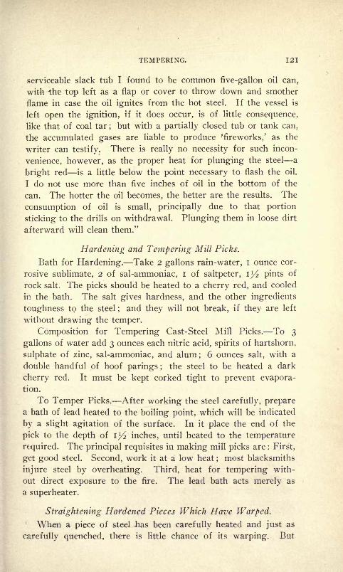
TEMPERING. 121
serviceable slack tub I found to be common five-gallon oil can,
with the top left as a flap or cover to throw down and smother
flame in case the oil ignites from the hot steel. If the vessel is
left open the ignition, if it does occur, is of little consequence,
like that of coal tar;but with a partially closed tub or tank can,
the accumulated gases are liable to produce 'fireworks/ as the
writer can testify. There is really no necessity for such incon-
venience, however, as the proper heat for plunging the steel a
bright red is a little below the point necessary to flash the oil.
I do not use more than five inches of oil in the bottom of the
can. The hotter the oil becomes, the better are the results. The
consumption of oil is small, principally due to that portion
sticking to the drills on withdrawal. Plunging them in loose dirt
afterward will clean them."
Hardening and Tempering Mill Picks.
Bath for Hardening. Take 2 gallons rain-water, I ounce cor-
rosive sublimate, 2 of sal-ammoniac, I of saltpeter, il/2 pints of
rock salt. The picks should be heated to a cherry red, and cooled
in the bath. The salt gives hardness, and the other ingredients
toughness to the steel;and they will not break, if they are left
without drawing the temper.
Composition for Tempering Cast-Steel Mill Picks. To 3
gallons of water add 3 ounces each nitric acid, spirits of hartshorn,
sulphate of zinc, sal-ammoniac, and alum;6 ounces salt, with a
double handful of hoof parings ;the steel to be heated a dark
cherry red. It must be kept corked tight to prevent evapora-
tion.
To Temper Picks. After working the steel carefully, preparea bath of lead heated to the boiling point, which will be indicated
by a slight agitation of the surface. In it place the end of the
pick to the depth of il/2 inches, until heated to the temperature
required. The principal requisites in making mill picks are : First,
get good steel. Second, work it at a low heat;most blacksmiths
injure steel by overheating. Third, heat for tempering with-
out direct exposure to the fire. The lead bath acts merely as
a superheater.
Straightening Hardened Pieces Which Have Warped.
When a piece of steel has been carefully heated and just as
carefully quenched, there is little chance of its warping. But
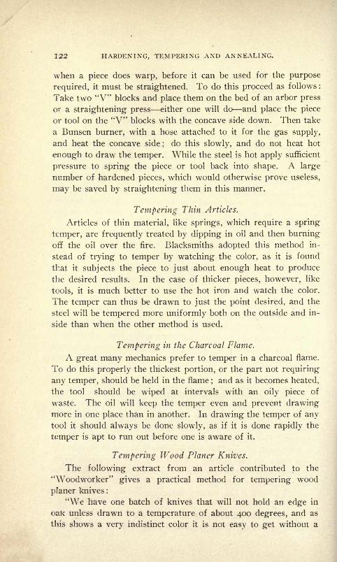
122 HARDENING, TEMPERING AND ANNEALING.
when a piece does warp, before it can be used for the purpose
required, it must be straightened. To do this proceed as follows :
Take two "V" blocks and place them on the bed of an arbor press
or a straightening press either one will do and place the piece
or tool on the "V" blocks with the concave side down. Then take
a Bunsen burner, with a hose attached to it for the gas supply,
and heat the concave side;
do this slowly, and do not heat hot
enough to draw the temper. While the steel is hot apply sufficient
pressure to spring the piece or tool back into shape. A large
number of hardened pieces, which would otherwise prove useless,
may be saved by straightening them in this manner.
Tempering Thin Articles.
Articles of thin material, like springs, which require a spring
temper, are frequently treated by dipping in oil and then burningoff the oil over the fire. Blacksmiths adopted this method in-
stead of trying to temper by watching the color, as it is found
that it subjects the piece to just about enough heat to produce
the desired results. In the case of thicker pieces, however, like
tools, it is much better to use the hot iron and watch the color.
The temper can thus be drawn to just the point desired, and the
steel will be tempered more uniformly both on the outside and in-
side than when the other method is used.
Tempering in the Charcoal Flame.
A great many mechanics prefer to temper in a charcoal flame.
To do this properly the thickest portion, or the part not requiring
any temper, should be held in the flame;and as it becomes heated,
the tool should be wiped at intervals with an oily piece of
waste. The oil will keep the temper even and prevent drawingmore in one place than in another. In drawing the temper of anytool it should always be done slowly, as if it is done rapidly the
temper is apt to run out before one is aware of it.
Tempering Wood Planer Knives.
The following extract from an article contributed to the
"Woodworker" gives a practical method for tempering wood
planer knives :
"We have one batch of knives that will not hold an edge in
oak unless drawn to a temperature of about 400 degrees, and as
this shows a very indistinct color it is not easy to get without a

TEMPERING. 123
thermometer. As these are 6, 8, and lo-inch knives, they cannot
be hardened in water without a reasonable certainty of cracking
back the length of the bevel in one or more places ;and as oil will
not carry off the heat fast enough to keep the body of the knives
from drawing the edge, it promised a serious problem to solve.
This was managed in the following manner, and after a few
trials I was able to obtain the proper degree of hardness without
drawing for temper at all.
"Take a vessel of proper width to receive the length of knife,
put some water in the bottom and pour an inch of oil on top.
Heat the edge of your knife an even cherry red back as far as
you wish to harden it, and holding it level thrust the edge into
the oil for a moment until the color leaves, then slowly let it downinto the water. The oil cools without cracking, and the water
prevents the heat in the body from drawing the edge. It is not
necessary to harden all long knives in this manner, as the oil
alone will produce a sufficient hardness in ordinary cases if a large
enough body of oil is used and the edge of the knife is immersed
with a stirring motion. It can then be tempered to about 500
degrees by the heat of the body of the knife and suddenly cooled
in water at about 80 degrees. These long knives are pretty sure
to warp some when tempering or hardening in this way, the back
or soft steel side contracting more than the face. To straighten,
lay face down on an anvil and with a round-nosed machinist's
hammer give a quick, sharp blow, distributed evenly between the
back edge bevel and the line of front end of slots. Be careful
to hammer directly over the spot resting on anvil or the knife
will vibrate in the hand and the force of the blow will be diffused
and lost. This gentle hammering stretches the back of the knife,
and when its length equals the face it will be straight."
Tempering Swords and Cutlasses.
The tempering of swords so that they will stand the United
States government test may be accomplished by heating in a char-
coal fire to a bright red and quenching in pure water, afterward
drawing the temper in a charcoal flame.
Drawing Polished Steel Articles to a Straiv Color or Blue.
The surface of polished steel articles will acquire a pale straw
color at 460 degrees F., and a uniform deep blue at 580 degrees F.
The other shades between these may be had at intermittent tem-
peratures.
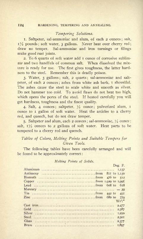
124 HARDENING, TEMPERING AND ANNEALING.
Tempering Solutions.
1. Saltpeter, sal-ammoniac and alum, of each 2 ounces; salt,
i]/2 pounds; soft water, 3 gallons. Never heat over cherry red;
draw no temper. Sal-ammoniac and iron turnings or filings
make good rust joints.
2. To 6 quarts of soft water add i ounce of corrosive sublim-
ate and two handfuls of common salt. When dissolved the mix-
ture is ready for use. The first gives toughness, the latter hard-
ness to the steel. Remember this is deadly poison.
3. Water, 3 gallons ; salt, 2 quarts ;sal-ammoniac and salt-
peter, of each 2 ounces;ashes from white ash bark, i shovelful
The ashes cause the steel to scale white and smooth as silver.
Do not hammer too cold. To avoid flaws do not heat too high,
which opens the pores of the steel. If heated carefully you will
get hardness, toughness and the finest quality.
4. Salt, 4 ounces; saltpeter, y2 ounce
; pulverized alum, i
ounce to i gallon of soft water. Heat the articles to a cherry
red, and quench, but do not draw temper.
5. Saltpeter and alum, each 2 ounces; sal-ammoniac, l/2 ounce ;
salt, iy2 ounces to 2 gallons of soft water. Heat parts to be
tempered to a cherry red and quench.
Tables of Colors, Melting Points and Suitable Tempers for
Given Tools.
The following tables have been carefully arranged and will
be found to be approximately correct :
Melting Points of Solids.
Deg. F.
Aluminum M57Antimony from 8n to 1,150
Bismuth from 476 to 512
Copper from 1,929 to 1,996
Lead from 608 to 618
Mercury 39Tin from 442 to 451
Zinc from 680 to 779
Wr't"
Cast iron 2,477
Gold 2,587
Silver 1,250
Steel 2,501
Glass 2,377
Brass '. 1,897

TEMPERING. 125
Melting Points of Solids Continued.
Wr't"Platinum 3,077
Cadmium 602
Saltpetre 600
Sulphur 225
Potassium 135
Table of Tempers to Which Tools Should be Drawn, Arranged
Alphabetically.
Tool. Color. Deg. of Tem. F.
AAugers Light purple 530
Axes Dark purple 550
All cutting tools for soft material Very light yellow 420
All hand taps and dies Straw yellow 460
All kinds of hand reamers Straw yellow 460
All percussion tools for metal Blue 549
BBone-cutting tools Very pale yellow 430
Boring cutters Straw yellow 460
Butt mills for brass Very light yellow 420
Burnishers Very light yellow 420
Bending and forming dies Dark yellow 490
CChasers Straw yellow 460
Coppersmiths' tools Light purple 530
Cold chisels for steel Light purple 530
Cold chisels for cast iron Dark purple 550
Cold chisels for wrought iron Light purple 530
Circular saws for metal Light purple 539
Cutting tools for iron Light yellow 440
Collets Dark yellow 490Chuck jaws Dark yellow 490Chisel for wood Spotted red-brown 510Clutch bolts Very dark blue 601
Cams with sharp corners Very dark blue 601
Clutch springs Blue 549
DDrifts Brown yellow 500Dental and surgical instruments Light purple 530
Drawing mandrels Very light yellow 420Drills for brass Straw yellow 460
EEdging . cutters Light purple 530
Embossing dies Light yellow 440

126 HARDENING, TEMPERING AND ANNEALING.
Table of Tempers to Which Tools 'Should be Drawn, ArrangedAlphabetically Continued.
Tool. Color. Deg. of Tern. &F
Flat drills for brass Brown yellow 500Flat drills for steel and iron Straw yellow 460
Firmer chisels Dark purple 550
Framing chisels Dark purple 550
GGimlets Dark purple 550
Gauges Brown yellow 500
HHammer faces ^ Very pale yellow 430Hand plane irons Brown yellow 500
Half-round bits Straw yellow 460
Hack saws Dark purple 550
Hand tools Light yellow 440Hand springs Purple blue 529 to 53 1
Hammers and drop dies Spotted red-brown 510
I
Ivory-cutting tools Very pale yellow 430
Inserted saw teeth Straw yellow : 460
J
Jaw pieces Purple blue 529 to 531
LLeather-cutting dies Straw yellow 460
Lathe tools for brass Very light yellow 420
Large cutting dies Straw yellow 460
Large forging dies for press Dark yellow 490
MMoulding and planing tools Dark purple 55
Milling cutters Straw yellow 460
Milling cutters for brass Very light yellow 420
NNeedles Dark purple 550
PPress dies for brass Light purple 53<>
Press dies for cold-rolled stock Brown yellow 500
Press dies for sheet steel Straw yellow 460
Press dies for leather Straw yellow 460
Press dies for paper Dark blue 570
Penknives Straw yellow 460
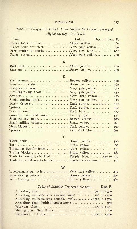
TEMPERING.
Table of Tempers to Which Tools Should be Drawn, ArrangedA Iphabetically Continued.
Tool. Color. Deg. of Tern. F.
Planer tools for iron Straw yellow 460Planer tools for steel Very pale yellow 430Parts subject to shock Very dark blue 601
Paper cutters Very pale yellow 430
RRock drills Straw yellow 460Reamers Straw yellow 460
S
Shell reamers Brown yellow 500
Screw-cutting dies Straw yellow 460
Scrapers for brass Very pale yellow 430
Steel-engraving tools Very pale yellow 430
Scrapers Very light yellow 420
Slight turning tools Very pale yellow . 430Screw drivers Dark purple 550
Springs , Dark purple 550Saws for wood Dark blue 570Saws for bone and ivory Dark purple 550
Stone-cutting tools Brown yellow 500Small milling cutters Straw yellow 460Shear blades Dark yellow 490
Springs Very dark blue 601
TTwist drills Brown yellow 500
Taps Straw yellow 460
Threading dies for brass Light yellow 440
Truing blocks Straw yellow 460Tools for wood, to be filed Purple blue 529 to 531
lools for wood, not to be filed Spotted red-brown 510
W.
Wood-engraving tools Very pale yellow 430
Wood-boring cutters Brown yellow 500.
Wire-drawing dies Straw yellow 460
Table of Suitable Temperatures for Deg. F.
Annealing steel 900 to 1,300
Annealing malleable iron (furnace iron) 1,100 to 1,400
Annealing malleable iron (cupola iron) 1,500 to 1,700
Annealing glass (initial temperature) 950
Working glass 1,200 to 1,475
Melting glass (into fluid) 2,200
Hardening tool steel 1,200 to 1,400
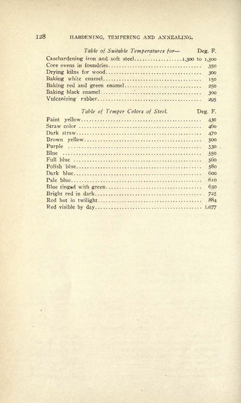
128 HARDENING, TEMPERING AND ANNEALING.
Table of Suitable Temperatures for Deg. F.
Casehardening iron and soft steel 1,300 to 1,500
Core ovens in foundries 350
Drying kilns for wood 300
Baking white enamel 150
Baking red and green enamel 250
Baking black enamel'
300
Vulcanizing rubber 295
Table of Temper Colors of Steel. Deg. F.
Faint yellow 430
Straw color 460
Dark straw 470
Brown yellow 500
Purple 530
Blue 550
Full blue 560
Polish blue 580
Dark blue 600
Pale blue 610
Blue tinged with green 630
Bright red in dark 725
Red hot in twilight 884
Red visible by day i ,077

CHAPTER VI.
CASEHARDENING PROCESSES THE USE OF MACHINERY STEEL FOR
CUTTING TOOLS AND THE TREATMENT OF IT.
The Use of Machine Steel for Press Tools.
For a large number of purposes, particularly in the line of
sheet metal working, machinery steel tools, if properly hardened,
will answer as well and sometimes better than tool steel ones, and
if the following process is used to harden such tools they will be
found to give the best of results and may be used with success for
cutting the different metals. In order that the parts or tools maydo their work and last long, they must be hardened very deep and
come out with a fine compact grain. For dies which are to be
used for punching regular shaped blanks from light soft stock,
machine steel casehardened tools will give excellent satisfaction,
as they are far cheaper to make and will last as long as thoughmade of tool steel.
Outfit for Fine Grain Casehardening.
To do this work properly the following outfit is necessary:
A good hardening oven, a number of hardening boxes, a good
supply of raw bone, granulated, the same amount of granulated
charcoal, some hydro-carbonated bone and the same amount
of charred leather. A tank large enough to hold a good supply
of water, a small tank so arranged as to allow of heating to anydesired temperature, and a bath of raw linseed oil, and the outfit
will be complete.
Packing and Heating the Work.
Pack and heat the work as you would for regular caseharden-
ing, and leave it in the oven to cool. When perfectly cool heat
the pieces in hot lead and quench the same as tool steel. If the
pieces are small they should be re-packed in the hardening box
with granulated charcoal and heated. When packing in charcoal
do not mix with any kind of bone or any other carbonizing mat-
ter; such substances open the grain, and the object of the second
heat is to close the grain. The hardening heat should be as low
as possible, and the hardened pieces will come out close in grain,

I3O HARDENING, TEMPERING AND ANNEALING.
with a hard, tough surface all over, while the center remains soft
and the piece will be stronger than if made of tool steel.
Casehardening Cutting Tools.
When machine steel tools are to be used for cutting they
should be packed for the first heat in a mixture composed of equal
parts of charcoal and charred leather, finely granulated. The use
of charred leather gives a much tougher effect, to the steel than
bone, as the leather is almost free from phosphorus, while bone is
not, and as phosphorus makes steel brittle the substance which
contains the least amount of it should be used. Tools which are
tc be used for bending and forming may be packed in bone, which
will carbonize them as required. When using either bone or
leather an equal amount of granulated charcoal mixed with it will
prevent the kernels of bone and leather from adhering and form-
ing a solid mass when hot, and as charcoal is an excellent con-
ductor the pieces packed within the hardening box will be heated
quicker than if no charcoal were used.
Plow to Caseharden, Color and Anneal with Granulated RawBone.
In order to attain good and satisfactory results in caseharden-
ing by the use of granulated raw bone, as well as to color and
anneal properly with it, the treatment of the steel must be in ac-
cordance with the use to which it is subsequently to be put. In
the following we give special directions for casehardening, color-
ing and annealing machine steel by the use of Hubbard's granu-
lated raw bone. The matter was kindly furnished to the author
by the manufacturers of the bone, Rogers & Hubbard Company,
Middletown, Conn., who have gone to much trouble and expense
in order to discover the best methods for casehardening, coloring:
and annealing under different conditions, and for parts used for
special purposes.
To Caseharden Without Colors.
Pack the work to be hardened in a cast-iron box. The box
should be of suitable size;use a box about 4 inches deep, 4 inches
wide and 8 inches long. Put a layer of granulated raw bone in
the bottom, then a layer of work to be hardened, and so on until
the box is full within 1^2 inches of the top. This space may be
filled with old bone that has been used. Put on the cover and
lid and lute with clay. In packing, be sure to keep the work at
CASEHARDENING PROCESSES. 13!
least one-half an inch from the sides and ends of the box. Heat
to a good cherry red from three to four hours, according to the
depth of hardening desired. Dump the whole contents in clear,
cool, soft water. Delicate pieces should be dumped in oil. Fot;
larger work use a larger box and keep in longer.
Hardening Extra Heavy Work.
To harden pieces 4 inches and upward in diameter the work
should be packed in clear raw bone, No. I or No. 2, surrounded
by at least il/2 to 2 inches of the "one," and heated to an orange,
or almost white heat, for 18 hours, and then plunged into cold
running water, salt water preferred. If the piece does not harden
hard enough at one operation, it should be repacked and heated
again, the same as the first time, and plunged into cold water as
before. Great care should be taken in heating these pieces. After
the heat is up to the required temperature, it should be kept so
until the piece is ready to be plunged into the water.
Hardening Drawbridge Disc and Similar Work.
Large flat pieces require especial care and treatment. For
hardening pieces or discs 2 feet in diameter and 4 inches thick, putfour or five inches No. I granulated raw bone in bottom of pack-
ing box. On this bed lay work to be hardened flat side down,
pack at least four inches of granulated raw bone around the
diameter and on top. If you have any charred leather, a thin
layer added next to the work may prevent scaling, but it is not
a necessity. After packing, cover the box with an iron cover and
lute with clay. Heat to a bright cherry red and hold at this heat
for eight or ten hours. These large flat pieces have a tendencyto warp a little, but this can be reduced to a minimum by being-
careful not to heat above a good cherry, and by dipping the pieces
edgewise into a large body of cold water, which has a steady
stream running into it, or some other way of keeping the water
agitated.
In hardening large flat pieces, there are four essential points;
plenty of bone; even, steady, bright cherry heat
; dip edgewise ;
large body of water that is kept agitated.
Hardening Five-inch Thrust Bearing Rings.
If made from ordinary soft machinery steel with about .10 per
cent or .15 per cent of carbon, it would be necessary to pack them
132 HARDENING, TEMPERING AND ANNEALING.
in No. 2 granulated raw bone and heat twelve hours to a good
bright cherry red, then re-pack and heat nine hours again to a
good bright cherry red. Dip in salt water singly (do not dump).We would advise using a cast-iron box n inches long, 7 inches
deep, 6 inches wide, covered with an iron cover that will fit inside.
Lute around the edge with clay. Such a box will hold ten rings.
To Harden Rods or Rolls, Leaving Tenons Soft for Riveting.
Finish the pieces to the required diameter, leaving a little extra
length for trimming, but do not turn the tenons on the end or ends.
Pack and heat the pieces as usual, but do not dump. Allow the
work to remain in the boxes until all heat has passed off the
same as the annealing. On being taken from the boxes the pieces
are thoroughly annealed with the outer surface carbonized to a
greater or less depth, according to the time they were in the
furnace. After turning the tenon heat the piece to a cherry and
plunge into cold water the same as to harden tool steel. On re-
moving from the bath the work will be found to be extremelyhard wherever the outer surface has not been removed since car-
bonizing, but wherever this surface has been removed, as in turn-
ing the tenon, the softness of the original stock has been removed.
If the stock is required in rods for tenon, screw or similar ma-
chines, cut in pieces as long as your furnace and pots will take,
carbonize and anneal as described above. The finished work from
these rods upon coming from the machines is ready to harden,
leaving such portions soft as have been turned or cut after car-
bonizing.
The principle of this method is that only carbonized portions
will harden when heated and chilled and as the carbon enters but
a short distance the carbonized surface may readily be removed,
thus leaving the original stock, which will not harden, exposed to
the action of the fire and water. The principle may be adapted to
a great variety of uses where hardness and softness are required
on the same piece.
When it is not practical to remove any of the stock in order
to remove the carbonized surface, the parts desired soft may be
protected by covering them with a coating of fire-clay, thus pre-
venting the carbonizing of the stock at these particular points,
with the result that when plunged in the cold bath they will re-
main soft.
CASEHARDENING PROCESSES. 133
To Caseharden Malleable Iron.
If malleable iron is thoroughly malleable it should be treated
exactly the same as any wrought iron. If it is only half annealed,
as some of it is, then there are no directions to give in regard to
it. Sometimes it will take a light casehardening, sometimes it
will harden half way through, other times all the way through,
according to the condition it is in. If it is thoroughly decar-
bonized, as it could be, then it is just about the same as a piece
of iron.
In order to obtain the best results it is' necessary to employa furnace that gives and maintains a good uniform heat.
To Use the Old Bone.
After dumping the pots, separate the bone from the work and
dry it thoroughly; it will then be coal black. This can be used
again by adding new granulated raw bone, about one part new to
two of the old. Place upon your bench a box each of the
granulated raw bone and the bone black;one is white, the other
black;a mixture will make a gray. For very small work, screws,
etc., use a dark gray, i. e., two or three parts bone black and one
of the raw bone. For very large work use white or raw bone ;
a little proportion of raw bone and burned bone to be used for
different sizes of work. The different shades of gray make an
easy and reliable guide after having once become familiar with
them.
Pameacha raw bone may be used in exactly the same way.The shades of the color are not as true a guide, however, as the
pameacha raw bone is quite dark-colored itself.
Constant burning will finally turn the bone white; it is then
valueless for casehardening.
Bone and Charcoal.
The following is recommended by a reliable party as a prac-
tical and economical method of using granulated raw bone : For
ordinary iron work, such as set or cap screws, etc., use one part
granulated raw bone to three parts pulverized charcoal, thoroughly
mixed; in this we pack our work in iron pots, then sprinkle a
little charcoal dust on the top. In casehardening Bessemer steel
or fine small drawn work we diminish the quantity of bone some-
what. Pameacha raw bone may be used in the place of the
granulated raw bone, but the proportion of charcoal should be
somewhat diminished.

134 HARDENING, TEMPERING AND ANNEALING.
Using the Tell-Talc.
Parties who have had but little experience in casehardening
may find the "tell-tale" a help to them. The tell-tale consists of
a piece of round iron, as near the size of the work to be hardened
as possible, that reaches down into the center of the pot, extending
up through the cover about high enough for the tongs. The hole
in the cover should be just large enough to allow the pin or tell-
tale to slip out readily. When you think the work has been in
long enough, remove the tell-tale with the tongs without dis-
turbing the pot, and plunge it immediately into cold water. There
may be one or more tell-tales in the cover, as desired. If the tell-
tale shows the work to be hardened to sufficient depth, dump as
instructed, otherwise leave in longer, and test as before.
To Obtain Colors with Granulated Raw Bone.
This process not only gives the finest colors and mottling, but
it casehardens the work at the same time.
Preparation of the Work.
To obtain bright" colors, the work must be nicely polished and
perfectly clean; poorly finished, greasy work will not take bright
colors. A clean, brightly polished surface is necessary for the
finest work.
To Char the Bone.
To produce the colors the granulated raw bone must be thor-
oughly charred. This can be easily and cheaply done by putting
it into iron boxes about 9 x 9 x 36 inches, covering tightly and
placing it in the furnace at night, after the work has been with-
drawn. The remnant of fire and heat of the retort is sufficient
to char the bone during the night. If, however, there is much
fire left, it must be partially deadened, as the object is to simply
char the bone without burning it. If the smaller boxes are used,
they must be watched and taken out when "one" is charred. If
there is sufficient oven room this can be arranged so as to be done
during the day.
. To Pack the Work.
Pack the work in a cast-iron box of suitable size for the work ;
for screws or similar work Y\ to ^4 mcn,use box 4 inches deep,
4 inches wide and 8 inches long. Put a layer of charred bone in
the bottom, then a layer of the work to be hardened and colored,
and so on until the box is filled to within i l/2 inches of the top;
CASEI1ARDENING PROCESSES. 135
fill this space with charred bone, put on the cover and lute with
day. In packing, be sure and keep the work at least y2 inch
from the sides and ends of the box, and do not let any two pieces
of the work come in contact.
The Heat.
Place the boxes in the furnace and bring to a cherry red, and
hold at this heat two to four hours. To get nice colors, the heat
must be held uniform;if too hot, there will be no color. A good
nice cherry red must be maintained from the time the boxes are
placed in the furnace until they are ready to dump. With very
small work this time may be reduced somewhat;with heavy work
it may be increased. A little practice will be necessary to deter-
mine this point.
In order to obtain the best results it is necessary to employ a
furnace that gives and maintains a good uniform heat.
The Bath.
While good colors can be obtained in rather hard water, yet
soft water will give much better results. The bath should be
arranged as follows : Bring your water pipe up through the bot-
tom of the barrel reaching about half way to the top ;make the
outlet about six inches from the bottom of the barrel; into your
supply pipe connect a pipe from an air pump so that the air and
water will mix in the pipe and come into the barrel together.
When dumping, have a running stream of water and air floating
into the barrel. Hang a sieve under the surface of the water in
which to dump the work. While the air pump is not absolutely
necessary, yet its use gives more satisfactory results. Runningwater is necessary if large lots are to be dumped, as the water
must be kept cold. Small lots may be dumped into the bath of
still water.
To Dump the Work.
When the work is ready to dump, draw the boxes from the
furnace, hold them close to the surface of the water over the sieve
and dump, turning over the box quickly. This operation requires
the nicest care, in order that the air may not strike the iron before
it reaches the water. If the air strikes the iron, it assumes a black
or blue-black streaked color.
Cleaning the Work.
Separate the work from the bone and boil out in clean water.

136 HARDENING, TEMPERING AND ANNEALING.
Dry in sawdust and oil over slightly, which will bring out the
color and keep it from tarnishing.
Colors from a Light Straw to a Deep Blue.
Caseharden the articles as instructed, then roll them in a
tumbling barrel of some sort, until they are brought to a properfinish. After they are thoroughly polished, place them in a cylin-
der and tumble them over a regular gas blaze until drawn to a
desired color, then plunge in cold water, dry in sawdust and oil
slightly to avoid tarnishing. By using a regular gas blaze, and
noting the exact time required, the process can be timed exactlyto produce any color desired from the light straw to a deep blue.
If preferred, you can put the pieces in a wire cylinder where youcan see the color, and revolve over a slow fire. The fire must be
free from gas or the pieces will be stained.
Directions for Annealing with Granulated Raiu Bone.
Pack the work to be annealed about the same as for case-
hardening, but it is not necessary to keep the pieces separate, usingthe bone that has been burned a number of times until it is almost
white. Place in the oven and heat until it is heated through to
a cherry red.
Cooling.
As soon as the work has reached the required heat stop the
blast, and if the oven is not required for further use, let the boxes
remain in the furnace and cool down with the fire. Upon remov-
ing the boxes from the oven cover them with warm ashes, old
burned bone or air-slacked lime, so as to retain the heat as longas possible. Do not remove the work from the boxes until all
heat has passed off. The more gradual the cooling the better
the results.
To Anneal Low Carbon S'teel Bars.
For bars 6^/2 inches in diameter use Q-inch iron pipe for pack-
ing box, other sizes in proportion. Pack the steel in a mixture of
half charcoal and half bone that has been used once or twice.
This proportion does not tend to recarbonize more than five (5)
per cent, and in all cases it is sufficient to maintain the amount of
carbon originally in the steel. Great care must be taken in heatingsteel for annealing, heating it only to the same degree of heat that
you would for casehardening, i. e., a good cherry red. Heavy bars
6 inches to 7 inches in diameter should be placed in the furnace
CASEHARDENING PROCESSES. 137
in the morning and left in until the next morning, but no draft
should be allowed on during the night. Upon removing the box
from the furnace cover them with warm ashes, old burned bone or
air-slacked lime, so as to retain the heat as long as possible. Donot remove the steel from the boxes until all heat has passed off.
Smaller bars are treated in exactly the same way except the
length of time required for heating ;this diminishes as the size of
the bar is reduced.
To Anneal Iron Castings.
To anneal small or thin iron castings, pack them in a cast-iron
pot with a mixture of bright cast-iron turnings or filings and
pulverized charcoal, half each; have a layer of the mixture be-
tween the castings ; it will help to keep them from warping and
heat them more uniformly. Place the pots in the oven and bringto a good bright cherry red, then let them cool off. If it is neces-
sary that they be very soft, hold them at a bright red for two or
three hours.
It is absolutely necessary that the castings be left in the pots
to cool off.
In order to obtain the best results it is necessary to employ a
furnace that gives and maintains a good uniform heat.
Casehardening with Cyanide of Potassium.
The casehardening of machinery steel with cyanide of potas-
sium can be accomplished in a number of different ways. Themost common method of casehardening with cyanide is to heat
the article to almost a white heat and soak it into a cake of the
cyanide, then reheat and plunge into water. This method, how-
ever, is a very poor one except for special jobs or a few small
articles.
A highly satisfactory method of casehardening with cyanidecan be attained by melting the cyanide in an iron pot, and dippingthe heated articles into it. To use this method for hardeningsmall articles a cast-iron pot will answer, while for large pieces
or ones with delicate portions, which are to be merely colored, a
mild steel pot will be necessary.
In Fig. 78 a cheaply made pot of the second kind is shown.
It can be made of flat mild steel from two pieces of J^-inch to
^-inch thick, which should be bent to the shape shown and riveted
and welded together. With a pot of this kind soft steel pieces maybe heated in the cyanide, and when dipped properly in water will
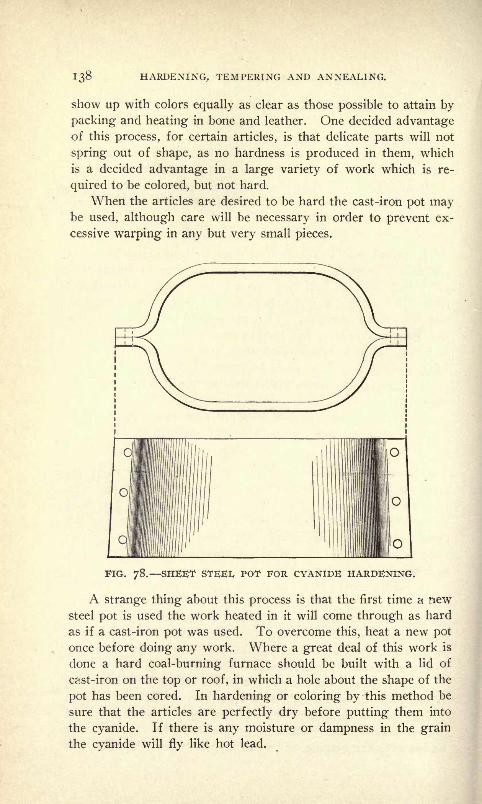
130 HARDENING, TEMPERING AND ANNEALING.
show up with colors equally as clear as those possible to attain by
packing and heating in bone and leather. One decided advantageof this process, for certain articles, is that delicate parts will not
spring out of shape, as no hardness is produced in them, which
is a decided advantage in a large variety of work which is re-
quired to be colored, but not hard.
When the articles are desired to be hard the cast-iron pot maybe used, although care will be necessary in order to prevent ex-
cessive warping in any but very small pieces.
FIG. 78. SHEET STEEL POT FOR CYANIDE HARDENING.
A strange thing about this process is that the first time a newsteel pot is used the work heated in it will come through as hard
as if a cast-iron pot was used. To overcome this, heat a new pot
once before doing any work. Where a great deal of this work is
done a hard coal-burning furnace should be built with a lid of
cast-iron on the top or roof, in which a hole about the shape of the
pot has been cored. In hardening or coloring by this method be
sure that the articles are perfectly dry before putting them into
the cyanide. If there is any moisture or dampness in the grain
the cyanide will fly like hot lead.
CASEHARDEN1NG PROCESSES. 139
Accurate Sectional Casehardening. .
The accurate sectional casehardening of special machinerysteel parts may be accomplished by a special process so that the
hard and soft surfaces may be controlled with absolute accuracy.
Take the article or part, of which sections only are desired to
be hardened, and coat the surfaces requiring hardening with black
Japan enamel, having first thoroughly cleaned the surfaces to be
afterward enameled, and after they are perfectly dry have the
work plated with copper, being sure that the Japan coating has
not been eaten away by any cleaning fluids.
After plating, the piece must be carbonized, which ordinarily
requires from three to four hours at a bright red heat in bone
dust. At this heat the pores of the metal open and freely absorb
the carbon. After the heating period has expired remove the
box and allow the article to cool slowly in the bone dust. Whenthe part is cold remove from the bone, heat to a red in an openfire and quench in cold water.
The fracture of a piece of metal treated as described above
will present a fine velvety appearance, this being brought about
through the second heating. If the part is quenched after the
first heating or working process, a coarse grain will be the crude
result.
Upon testing the properly heated piece with a file, it will be
found that, the plated surfaces are soft and the Japanned ones hard.
This result comes about through the copper plating preventing the
absorption of carbon during the roasting process and the Japan
burning off and allowing the opposite to occur, allowing the carbon
to penetrate to a depth of 1-16 inch. By repeating the process
the hardened surface will deepen and the structure of the metal
will not deteriorate.
To Produce Fine Grained Hardened Machine Steel Parts.
The reason why machinery steel has not been adopted and used
extensively in place of expensive tool steel is that very few me-
chanics are able to harden it so as to produce a fine grain. Whenit is considered that machine steel would replace to advantage
many tool steel parts if the process for producing a fine grain was
generally known the value of the method is obvious.
All steel parts which are subjected to pressure, wear, or con-
cussion are required to have a strong close-grained backing in
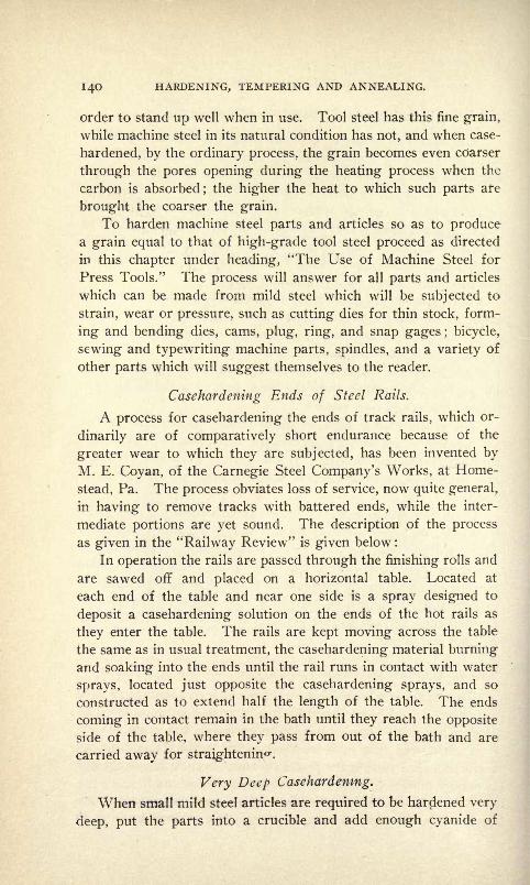
I4O HARDENING, TEMPERING AND ANNEALING.
order to stand up well when in use. Tool steel has this fine grain,
while machine steel in its natural condition has not, and when case-
hardened, by the ordinary process, the grain becomes even coarser
through the pores opening during the heating process when the
carbon is absorbed;the higher the heat to which such parts are
brought the coarser the grain.
To harden machine steel parts and articles so as to producea grain equal to that of high-grade tool steel proceed as directed
in this chapter under heading, "The Use of Machine Steel for
Press Tools." The process will answer for all parts and articles
which can be made from mild steel which will be subjected to
strain, wear or pressure, such as cutting dies for thin stock, form-
ing and bending dies, cams, plug, ring, and snap gages ; bicycle,
sewing and typewriting machine parts, spindles, and a variety of
other parts which will suggest themselves to the reader.
Casehardening Ends of Steel Rails.
A process for casehardening the ends of track rails, which or-
dinarily are of comparatively short endurance because of the
greater wear to which they are subjected, has been invented by
M. E. Coyan, of the Carnegie Steel Company's Works, at Home-
stead, Pa. The process obviates loss of service, now quite general,,
in having to remove tracks with battered ends, while the inter-
mediate portions are yet sound. The description of the process
as given in the "Railway Review" is given below :
In operation the rails are passed through the finishing rolls and
are sawed off and placed on a horizontal table. Located at
each end of the table and near one side is a spray designed to
deposit a casehardening solution on the ends of the hot rails as
they enter the table. The rails are kept moving across the table
the same as in usual treatment, the casehardening material burning
and soaking into the ends until the rail runs in contact with water
sprays, located just opposite the casehardening sprays, and so
constructed as to extend half the length of the table. The ends
coming in contact remain in the bath until they reach the opposite
side of the table, where they pass from out of the bath and are
carried away for straightenin -.
Very Deep Casehardening.
When small mild steel articles are required to be hardened very
deep, put the parts into a crucible and add enough cyanide of

CASEHARDENING PROCESSES. 14!
potash to cover them when melted. Cover the crucible and heat
as required, then remove parts and quench into a cold water bath.
Parts treated in this manner will harden very deep.
To Caseharden Small Iron Parts.
Put into an iron pot, or crucible, I part prussiate of potashand 10 parts of common salt, fuse together, and put articles in.
Allow the parts to remain in the liquid for 30 minutes, after which
quench in cold water, and a good caseharden will result.
To Caseharden with Charcoal.
To caseharden with charcoal, the articles finished, but not pol-
ished, should be put into an iron pot, and covered with an animal
or vegetable charcoal, and brought to a red heat, when they will
cement. The heat should be kept up for a period varying with the
size and description of the articles worked upon.
Moxon's Method of Casehardening.
Cow's horn or hoof is to be baked or thoroughly dried and
pulverized in order that more may be packed in the box with the
articles to be worked upon. Bones reduced to dust will answer the
same purpose. To this add an equal quantity of bay salt;mix
then with this stale chamber-lye, cover the iron with this mixture,
and bed it in the same as loam, or inclose it in an iron box. Layit on the hearth to dry and harden, and then put into the fire. Heat
the mass until a blood red heat no higher appears, and then
remove the iron and quench in cold water.
A Casehardening Mixture for Iron.
A good Casehardening mixture for iron is composed of equal
parts prussiate of potash, sal-ammoniac and saltpeter; add 4^ounces more of sal-ammoniac and 7 gallons of water. Heat the
iron red hot and soak it in the composition.
A Casehardening Paste.
To caseharden iron parts quickly and satisfactorily, make a
paste with a concentrated solution of loam and prussiate of potash.
Coat the parts to be hardened with the paste and heat them to a
bright red, after which allow them to cool to a dull red and then
quench in a cold water bath.
142 HARDENING, TEMPERING AND ANNEALING.
Casehardening Polished Parts.
To caseharden mild steel or iron parts which have been pre-
viously finished and polished, heat them to a bright red in a closed
fire and wipe them with prussiate of potash. When the prussiate
appears to decompose and dissipate, quench the article or part in
cold water. When the process has been conducted properly the
surface of the parts will be well hardened to a depth sufficient to
resist a file. This process will be found to be a great improve-
ment over the ordinary method as the application of the prussiate
allows of casehardening a part, or a number of parts, of the ar-
ticles and still leave the remaining sections soft.
Casehardening as it Should be Understood.
In order to caseharden successfully it is not merely necessary
to follow the directions herein given. The principles must be un-
derstood and retained in order that the operation shall be accom-
plished in a manner fitting special requirements. In the first place
the operation of casehardening consists first and foremost of givinga surface to steel or iron that will be capable of receiving a great
external hardness, while the interior remains soft and in its natural
tough state. Thus the part will be capable of withstanding wear,
strain and concussion when in use. Second, the above mentioned
results can only be accomplished satisfactorily by packing and heat-
ing the parts in close vessels filled with animal carbon.
The following being kept in mind, no difficulty will be experi-
enced in performing casehardening operations successfully : Pack
in a good animal carbon, make the box air-tight by luting with
clay, place in fire and keep at a red heat for a length of time suffi-
cient to allow of hardening to the depth desired a half hour of
heat will allow of hardening 1-32 inch deep, an hour 1-16 inch,
two hours l/& inch, and so forth, the longer the heating period the
greater the depth to which the pieces will be hardened. After the
heating period has elapsed the parts may be taken from the box
and quenched in cold water, or better still, they may be reheated
to a cherry red and then quenched. When cool, remove from the
water and dry thoroughly, to prevent rusting, by riddling them in
a sieve with dry sawdust. To keep delicate articles from blistering
during the heating process, dip them into a powder of burnt bones,
leather, or some other coaly animal matter.
CHAPTER VII.
HARDENING AND TEMPERING MILLING CUTTERS AND SIMILAR TOOLS,
Hardening Milling Cutters in the Open Fire.
For the hardening of milling cutters and tools of a similar na-
ture, water or brine is mostly used, the liquid being kept in a tank
with an exhaust pipe and a supply pipe connected with it. Solu-
tions are used to some extent and good results are obtained. Onthe whole, however, success in hardening such tools depends prin-
cipally upon the man who does the heating and quenching.To harden a milling machine cutter in the open fire, have a
large, high charcoal fire and bury the cutter well in it and use only
enough blast to heat the work to the required temperature, being*
careful to get the heat uniform throughout. If the cutter has not
been annealed after roughing and drilling the hole through it, re-
move it from the fire when red hot and allow it to cool off slowlyuntil a black appears. It can then be again placed in the fire,
slowly brought to the required heat, plunged into the bath of tepid
water or brine and worked around well until it stops "singing."
At this point it should be removed and instantly plunged in the oil
bath and left there until it is cool, when the strain should be re-
moved by holding over the fire until it is warm enough to snapwhen touched by a drop of water. It can then be laid aside and
the temper drawn at leisure. In hardening punch press dies theycan be treated the same
;if there are any screw holes for stripper
or guide screws they should be filled with fire clay, graphite or
asbestos. Much depends on an even, uniform heat;uneven heat
causes more cutters and dies to crack than high heat. Steel should
never be given any more heat than is necessary for the operationdesired.
Hardening Large Milling Cutters.
Large, plain or former milling cutters, say over $]/2 inches in
diameter and 4 inches long, to harden should be packed in a mix-
ture of equal quantities of granulated charred leather and charcoal,
taking care not to have any part of the mill within, say, 2 inches of
the box at any point. Keep it in the furnace for 4 to 4^2 hours
after the box is heated through to a low red;remove the box from

144 HARDENING, TEMPERING AND ANNEALING.
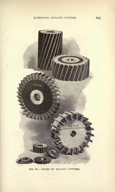
HARDENING MILLING CUTTERS. 145
FIG. 80. TYPES OF MILLING CUTTERS.

146 HARDENING, TEMPERING AND ANNEALING.
the furnace at the expiration of the time and quench the cutter in
a bath of raw linseed oil, twirling it around rapidly in the oil so as
FIG. 8l. SPECIAL FORM-ING CUTTER.
FIG. 82. DOUBLE FACEMILL.
to cause the oil to come in contact with the teeth. Allow the
cutter to remain in the oil until cold. A formed mill with heavy
teeth does not need to have the temper drawn. Mills with
FIG. 83. GANG OF STRAIGHT-FACED MILLING CUTTERS.
teeth cut in the ordinary manner should be run quite as long, and
may be drawn for ordinary work to a light straw color, or if drawn

HARDENING MILLING CUTTERS. 147
In a kettle gaging the heat by a thermometer to 425 or 430 degrees
Fahr.
We have seen a large number of milling cutters and similar
tools treated by this method and have never known one to be lost
by cracking. In years of experience with this method we have had
but a few pieces crack.
Hardening and Tempering Milling Cutters in Water and Oil.
A rapid and highly satisfactory method for hardening and
tempering milling cutters is by the combined oil and water method.
FIG. 84. GANG OF MILLING CUTTERS FOR MACHINING AWIDE-FORMED SURFACE.
When only a small quantity of such tools are required, this method
will be found superior to the ordinary hardening and temperingmethod.
The method is as follows;The cutter to be hardened is heated
FIG. 85. FORMED FACE MILL. FIG. 86. SHELL END MILL.
to a proper uniform temperature, quenched into a cold-water bath
and left there long enough to harden the outside only, but not
enough to cool the steel clear through. It is then taken from the
water as quickly as possible and plunged into lard oil and held

148 HARDENING, TEMPERING AND ANNEALING.
there until the outside is almost cold. The tool is then taken from
the oil and the'
'temper7 '
immediately drawn by allowing the heat
remaining in the core of the tool to draw the teeth; this may be
aided to some extent by holding the tool in the flame of the forge
or furnace. The reheating should be continued until the oil com-
mences to smoke. To insure an even temper it is best to then
FIG. 87. GANG OF CUTTERS.
plunge the tool for an instant into the oil and again heat, doing
this several times until the smoke rises evenly from all over the
tool. This second plunge into the oil tends to cool off any fine
points that might become overheated, while the tool is not left in
the oil long enough to cool off the thicker parts, thus insuring a
more uniform and evener heat than would be the case if the tool
were heated all at once.
Advantages of the Method.
The above-described method may seem to some to be a more
FIG. 88. SPECIAL MILLING CUTTER.
tedious one than that ordinarily used, but as the time saved is con-
siderable, and the results, particularly in experienced hands, are
much more reliable, it should be adopted where good milling cut-
ters are required.
The ordinary method of tempering tool-steel milling cutters is
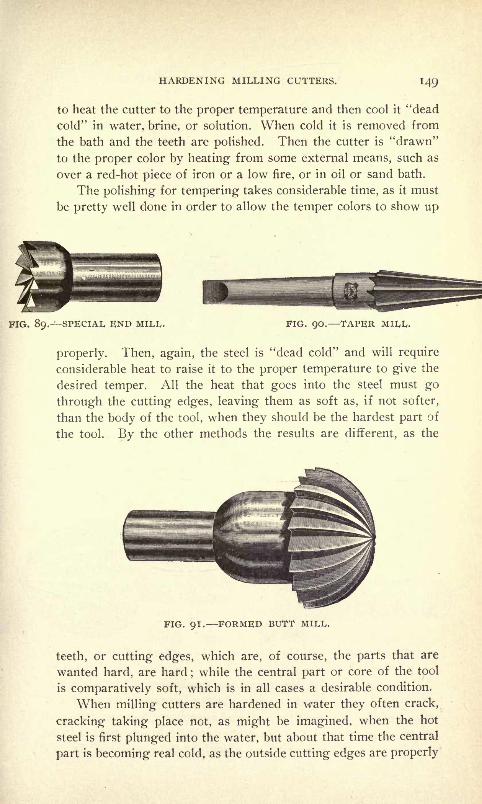
HARDENING MILLING CUTTERS. 149
to heat the cutter to the proper temperature and then cool it "dead
cold" in water, brine, or solution. When cold it is removed from
the bath and the teeth are polished. Then the cutter is "drawn"
to the proper color by heating from some external means, such as
over a red-hot piece of iron or a low fire, or in oil or sand bath.
The polishing for tempering takes considerable time, as it must
be pretty well done in order to allow the temper colors to show up
FIG. . SPECIAL END MILL. FIG. 90. TAPER MILL.
properly. Then, again, the steel is "dead cold" and will require
considerable heat to raise it to the proper temperature to give the
desired temper. All the heat that goes into the steel must go
through the cutting edges, leaving them as soft as, if not softer,
than the body of the tool, when they should be the hardest part of
the tool. By the other methods the results are different, as the
FIG. 91. FORMED BUTT MILL.
teeth, or cutting edges, which are, of course, the parts that are
wanted hard, are hard;while the central part or core of the tool
is comparatively soft, which is in all cases a desirable condition.
When milling cutters are hardened in water they often crack,
cracking taking place not, as might be imagined, when the hot
steel is first plunged into the water, but about that time the central
part is becoming real cold, as the outside cutting edges are properly
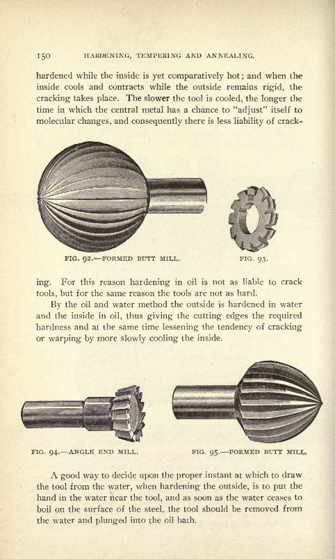
150 HARDENING, TEMPERING AND ANNEALING.
hardened while the inside is yet comparatively hot;and when the
inside cools and contracts while the outside remains rigid, the
cracking- takes place. The slower the tool is cooled, the longer the
time in which the central metal has a chance to "adjust" itself to
molecular changes, and consequently there is less liability of crack-
FIG. 92. FORMED BUTT MIU,.
ing. For this reason hardening in oil is not as liable to crack
tools, but for the same reason the tools are not as hard.
By the oil and water method the outside is hardened in water
and the inside in oil, thus giving the cutting edges the required
hardness and at the same time lessening the tendency of cracking
or warping by more slowly cooling the inside.
FIG. 94. ANGLE END Mil,!,. FIG. 95. FORMED BUTT Mil,!,.
A good way to decide upon the proper instant at which to draw
the tool from the water, when hardening the outside, is to put the
hand in the water near the tool, and as soon as the water ceases to
boil on the surface of the steel, the tool should be removed from
the water and plunged into the oil bath.

HARDENING MILLING CUTTERS. 15!
The object of this cooling first in water and then in oil is this :
The outside of the tool is wanted very hard;the inside somewhat
softer. The faster the heat is abstracted from the heated tool, the
harder it becomes;so by first plunging it into the water the cutting
edges are given the desired degree of hardness, and as soon as
they are hardened, the tool, with the central part still hot, is
FIG. 96. SPECIAL, FORMED BUTT MILL. FIG. 97. END MILLS.
plunged into oil;and as the oil does not abstract the heat as fast
as the water, the steel has more time to adjust itself to molecular
motion and there is less tendency to crack. Again, the oil left
on the outside of the tool serves as an indicator for determiningthe temperature at which to reheat the steel to give the proper
temper. As the tool is not completely cooled in the oil, very little
. 98. SPECIAL MILL.
external heat is required to draw it. In fact, the drawing of the
temper really begins immediately upon removing the tool from
the water bath.
Lard oil is the best to use in tempering in this way, and it has
been found that the oil commences to show a very faint smoke at
about the same temperature as a light straw;the proper temper
may be considered as reached when the smoke is seen comingfrom all parts of the tool.
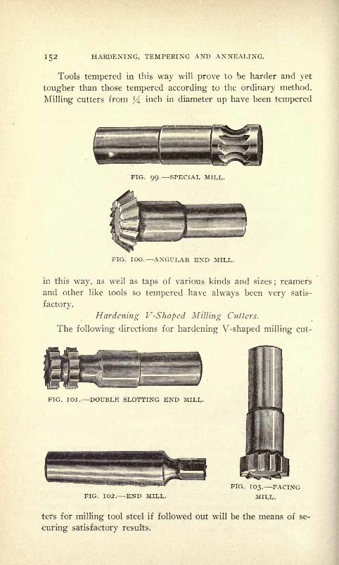
152 HARDENING, TEMPERING AND ANNEALING.
Tools tempered in this way will prove to be harder and yet
tougher than those tempered according to the ordinary method.
Milling cutters from y\ inch in diameter up have been tempered
FIG. 99. SPECIAL
FIG. 100. ANGULAR END MILL.
in this way, as well as taps of various kinds and sizes;reamers
and other like tools so tempered have always been very satis-
factory.
Hardening V-Shapcd Milling Cutters.
The following directions for hardening V-shaped milling cut-
FIG. 101. DOUBLE SLOTTING END MILL.
FIG. 102. END MILL.
FIG. 103. FACING
MILL.
ters for milling tool steel if followed out will be the means of se-
curing satisfactory results.

HARDENING MILLING CUTTERS. 153
Heat the cutters in a gas furnace, open fire or in a hot lead
bath. Not so much depends on the means used for heating as
upon how hot and whether uniformly heated;and as to lead stick-
ing to the work, if it is used, there should be little trouble if purelead is used with plenty of broken charcoal on top to prevent
oxidation;but if there is still trouble it can be avoided by coating
the article with salt before putting into the lead-heating bath.
This is easily done by warming the work up to a blue and dipping
in a strong solution of salt and water.
In hardening, the cutters may be cooled in cold water or brine,
temperature depending on the character of cutter, whether very
FIG. 104. HOLLOW MILLS.
;delicate or not. With some 'heavy cutters it might be ice cold,
while in the case of very thin, delicate cutters it would be better
to have the bath up to blood heat or even higher ;it is simply a
question of preventing cracking.
Remove the cutters from the cooling bath as soon as the teeth
have cooled sufficiently to harden, and instantly immerse them in
oil to remain there, if convenient, until cold.
How to Harden Hollow Mills.
When hollow mills are to be hardened, care should be taken
when heating not to heat very much above the teeth, as it is not
necessary for the back to be hard. When the proper heat has
<been attained, the mill should be inverted and hardened in the
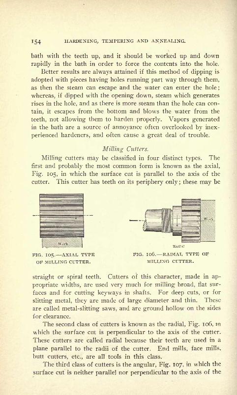
154 HARDENING, TEMPERING AND ANNEALING.
bath with the teeth up, and it should be worked up and down
rapidly in the bath in order to force the contents into the hole.
Better results are always attained if this method of dipping is
adopted with pieces having holes running part way through them,
as then the steam can escape and the water can enter the hole;
whereas, if dipped with the opening down, steam which generates
rises in the hole, and as there is more steam than the hole can con-
tain, it escapes from the bottom and blows the water from the
teeth, not allowing them to harden properly. Vapors generated
in the bath are a source of annoyance often overlooked by inex-
perienced hardeners, and often cause a great deal of trouble.
Milling Glitters.
Milling cutters may be classified in four distinct types. Thefirst and probably the most common form is known as the axial,
Fig. 105, in which the surface cut is parallel to the axis of the
cutter. This cutter has teeth on its periphery only ;these may be
IG. 105. AXIAL TYPEOF MILLING CUTTER.
Badia!
FIG. 1 06. RADIAL TYPE OF
MILLING CUTTER.
straight or spiral teeth. Cutters of this character, made in ap-
propriate widths, are used very much for milling broad, flat sur-
faces and for cutting keyways in shafts. For deep cuts, or for
slitting metal, they are made of large diameter and thin. These
are called metal-slitting saws, and are ground hollow on the sides
for clearance.
The second class of cutters is known as the radial, Fig. 106, in
which the surface cut is perpendicular to the axis of the cutter.
These cutters are called radial because their teeth are used in a
plane parallel to the radii of the cutter. End mills, face mills,
butt cutters, etc., are all tools in this class.
The third class of cutters is the angular, Fig. 107, in which the
surface cut is neither parallel nor perpendicular to the axis of the
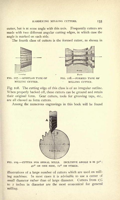
HARDENING MILLING CUTTERS. 155
cutter, but is at some angle with this axis. Frequently cutters are
made with two different angular cutting edges, in which case the
angle is marked on each side.
The fourth class of cutters is the formed cutter, as shown in
PIG. 107. ANGULAR TYPE OFMILLING CUTTER.
Form
FIG. 1O8. FORMED TYPE OF
MILLING CUTTER.
Fig. 1 08. The cutting edge of this class is of an irregular outline.
When properly backed off, these cutters can be ground and retain
their original form. Gear cutters, tools for grooving taps, etc.,
are all classed as form cutters.
Among the numerous engravings in this book will be found
FIG. 109. CUTTER FOR SPIRAL MILLS. INCLUSIVE ANGLE B IS 52 ;
40 ON ONE SIDE, 12 ON OTHER.
illustrations of a large number of cutters which are used on mill-
ing machines. In most cases it is advisable to use a cutter of
small diameter rather than of large diameter. Cutters from il/>
to 2 inches in diameter are the most economical for general
milling.

CHAPTER VIII.
HARDENING, TEMPERING AND STRAIGHTENING ALL KINDS OF
SMALL TOOLS.
Hardening Ring Gages.
To harden ring gages and other tools of a similar nature so
that they will harden around the hole and leave the remaining
parts soft, clamp the tool between flange-ended tubes and allow
FIG. IIO. U. S. STANDARD THREAD GAGES, EXTERNAL
AND INTERNAL.
a stream of water or brine to circulate through them. By this
method the walls will harden out as far as the inner edges of the
clamping flanges.
Dipping Small Tools When Hardening.
When small tools such as penknife blades, razor, lancet, chisel,
gage-bit, place spoke sheaves, three and four square files, round
and flat files, iron-shaving knives are to be hardened great care
must be taken to dip them into the quenching bath endwise or
perpendicularly. By doing this they will come out straight,
while, on the contrary, if they are slanted while dipping, there
will be a tendency to warp.

HARDEN, TEMPER AND STRAIGHTEN SMALL TOOLS. 157
Dipping Half-Round Reamers When Hardening.
When hardening half-round reamers or any other tools that
are solid and half-round, enter them at an angle of about twenty
degrees with the surface of the bath. This will tend to keep them
straight. In a half-round tool there is once and a half as much
surface in the half-round portion to be hardened as on the flat
side, and as in hardening the contraction of the steel is equal,
according to the surface, it is necessary to dip the half-round
side at the angle mentioned. As the half-round portion has a
greater percentage of contraction than the flat side, the unequal
contraction will draw the reamer to one side and warp it.
Dipping Fluted Reamers When Hardening.
When hardening fluted reamers, dip them perpendicularly to
a short distance beyond the fluting, that is to say, about half an
inch, and withdraw and return them a number of times. This
will harden all the lips, and prevent them from cracking off at
FIG. III. COUNTERSINK. FIG. 112. SMALL ANGLE MILL.
the water's edge, which is usually the case when a piece of steel
is dipped into a certain depth and allowed to cool without moving.A number of different tools are often broken off at the ends in this
way, without anyone knowing what caused them to crack.
Straightening Tools Which Have Warped in Hardening.
When a piece of steel which has been hardened and tempered
is found to have sprung, it may be straightened as follows : Heat
it slightly, not enough to draw the temper, and it may be straight-
ened on the anvil with a hammer. This cannot be done when the
piece is dead cold. It is best, however, to straighten a piece when-
ever possible between the centers of a lathe, or on a block of wood
with a mallet. Warm, the steel will yield readily to the blows of
the mallet, but cold, it will break like glass.
A sword blade which has warped in hardening may be ham-
mered flat ; too much hammering, however, will cause the blade
to lose its elasticity. When this occurs it may be returned to its
elastic state again without re-hardening by heating slowly to a

158 HARDENING, TEMPERING AND ANNEALING.
spring temper. This method may be adopted to advantage for
other kinds of work also.
Hardening Very Thin Tools so as to Prevent Warping.
A good way to harden very thin tools so as to insure against
their warping is to heat them carefully and stick them into a raw
potato. Then remove and temper as desired over a gas flame.
Warping of Long Tools in Hardening.
Trouble with the warping or the twisting of long tools, such
as taps and reamers, in hardening and tempering, can be avoided
FIG. 113. INSERTED CUTTER PIPE TAP.
if care is taken. If, in hardening, one can so manage as to retain
a soft center in the article there will be, or need be, but little
difficulty in overcoming the warp. This will at least be found
true in large tools which have a larger proportion of soft core than
those of smaller cross-section. With these last, and in fact, in
all, care must be taken to lower the tool perfectly square into the
quenching bath, so that the heat will be absorbed equally from all
sides. This desirable tendency will be increased if the tool is
lowered in the center of the bath.
If the above is true about the hardening bath, it is equally

HARDEN, TEMPER AND STRAIGHTEN SMALL TOOLS. 159
so of the heating bath, where melted lead or other liquids are used
for heating. One thing must be remembered, and that is that
there will be no use in taking the trouble to cool a tool equally if
it has been heated unequally. For this reason, tools should be
immersed squarely and centrally into the heating-bath, and turned
around. The turning process will also contribute to good results
in quenching.
Temperature((Tell-Tales" for Use in Heating Steel.
In order to show just how hot steel is that is being annealed
in a muffle or box, supply some one-fourth inch rods, which may be
pulled out from time to time to test the temperature.
Working Steel for Tools.
In forging steel for tools great care must be taken to hammerall sides alike. The careless and unequal hammering of steel
when forging is responsible for a great deal of bad work in hard-
ening. Another thing, steel, when being forged, should be heated
as hot as it will stand until finishing, and should then be ham-
mered until almost black-hot. This treatment will set the grain
of the steel finer, and give a tool a better edge when finished. Thereason for heating the steel to a bright red heat while forging is
simply because it makes the steel tougher when hardened and
softer when annealed; while, on the contrary, when steel is worked
at a low red heat, the continued shocks of the hammer will so
harden it as to make it almost impossible to anneal it, and at the
same time render it too brittle, when hardened, for general use.
Hardening Small Saivs.
To harden small saws such as are used for screw head slotting,
etc., heat on a flat surface and clamp between two thick cast-iron
plates, which should be perfectly level and coated with a heavy
grease.
Hardening Cutter-Bits.
Cutter-bits such as are used in lathe tool holders should be
hardened regularly when soft at the lower ends. When too soft
to use they should be laid aside until a sufficient number of them
are at hand to be hardened. They can then be heated by puttingthem into a box and heating them to a dull red, and the end of
each stuck into a perforated iron pan, the bottom of which should

l6o HARDENING,, TEMPERING AND ANNEALING.
be covered with just a sufficient depth of water to harden them
up as far as desired. The tools may then be ground and put with
the new cutters. Do not let high-grade steel such as should be
.used for cutter-bits get into the smith's fire.
Hardening Mixture for General Smith Work.
Salt, 2 ounces; copperas, il/2 ounces; sal-ammoniac, 1^2
ounces; saltpeter, i l/2 ounces; sal-soda, il/2 ounces, and black
oxide magnesia, 8 ounces. The last two ingredients should be
added after the others are mixed together. Before mixing the
ingredients, pulverize them separately, and then mix well and dry
before using. Use like yellow prussiate of potash and plunge in
water.
Tempering Flat Drills for Hard Stock.
Procure good high degree steel and heat to a cherry red, and
hammer until nearly cold, forming the end into the requisite
flattened shape, then heat it again to a cherry red, and plunge it
into a lump of resin or into quicksilver. A solution of cyanide
of potassium in rain water is sometimes used for the tempering
plunge-bath, but it will not give the result that quicksilver or resin
will.
To Temper Gravers.
Gravers may be tempered in the same way as drills ; or the
red-hot tool may be pressed into a piece of lead in which a hole
about half an inch deep has been cut to receive the graver; the
lead melting around the article will give it an excellent temper.
To Temper Old Files.
Grind out the cuttings on one side of the file until a bright
surface is obtained;then moisten the surface with a little oil,
and place the file on a piece of red-hot plate with the bright side
upward. In about a minute the bright surface will begin to turn
yellow, and when the yellow has deepened to about the color of
straw, plunge in cold water.
Hardening and Tempering Small Taps, Knives, Springs, Etc.
Secure a piece of pipe of sufficient diameter and length to ac-
commodate the piece, and heat one end, flatten together on the
anvil, and weld so it will not leak. Fill the pipe with lead and
set it up in the fire. When the lead has melted, immerse the tool

HARDEN, TEMPER AND STRAIGHTEN SMALL TOOLS. l6l
and let it remain until the lead is red-hot. Then quench in a
salt water bath and when cool remove it. To temper the tool, heat
a large piece of iron in the forge to a red heat. Grease the tool
all over with tallow. Remove the iron from the forge and lay on
the anvil. Hold the tool over hot iron by means of tongs or
pliers, turning it all the time until the desired color is obtained
and then drop it into linseed oil. A good and uniform tempershould result.
Tempering Small Spiral Springs.
To temper small spiral springs heat to a cherry red in a char-
coal fire, and harden in oil. To temper, blaze off the oil three
times;the same as for small flat springs.
To Draw Small Steel Parts to a Blue.
Fill a cast-iron box with sand and heat it red hot. Then putthe article, which has been first highly polished, into the sand and
when the right color appears remove and quench in oil.
Small steel parts of guns, typewriters, sewing machines, etc.,
may be blued cheaply and well in a solution of ten parts saltpeter
and black oxide of manganese, heated in an iron pot to the point
where sawdust thrown on it will flash.
Small pieces may be strung on wires in considerable quanti-
ties and dipped in solution, a minute or two being sufficient time
ordinarily, although of course this will vary with the thickness of
the pieces. The blue produced by this process is what is called
Government Blue and is not quite equal to the English Blue, which
is secured with hot charcoal and whiting, as all gunmakers will
understand, but it will answer very well and is very much cheaper.
If springs are to be blued, they may be hardened and polished
and the bluing process will draw them to the proper temper at
the same time, and the temper will be very uniform.
It will be well to bore some holes in the solution before plac-
ing on the fire to heat, for if a vent is not provided there will be
a commotion.

CHAPTER IX.
THE HARDENING AND TEMPERING OF DIES AND ALL KINDS OF
PRESS TOOLS FOR THE WORKING OF SHEET METAL.
The Hardening and Tempering of Press Tools.
Of the hardening and tempering of dies and all manner of
press tools too much cannot be written, as upon the results of
this part of their construction depends the efficiency of the tools.
For heating dies a gas furnace is preferable, but when this is not
at hand a good clean charcoal fire will do.
For hardening large dies it is indispensable to have a large
tank which should be arranged in such a manner as to insure the
rapid cooling of the steel. A tank of this kind can be arranged
by fixing two or three rods across the inside about 12 inches
below the surface of the water, and a pipe let into the tank in
such a manner as to allow of a circulation of a stream of water
FIG. 114. COMBINATION DIES, WITH HARDENED AND GROUND TOOLSTEEL WORKING PARTS SOLID-EORGED TO WROUGHT-IRON PLATES.
from the bottom upward. When the die is to be quenched the
water should be turned on and kept running until the steel has
cooled. When a good circulation of water is kept up in the tank
there will not be any soft spots in the die after hardening.It is often necessary to construct dies from forgings of
wrought iron and tool steel, and, as the dies when finished are
required to be hardened, it is necessary there should be a goodweld between the two parts. To accomplish this result, when
welding mix mild steel chips, from which all of the oil has been
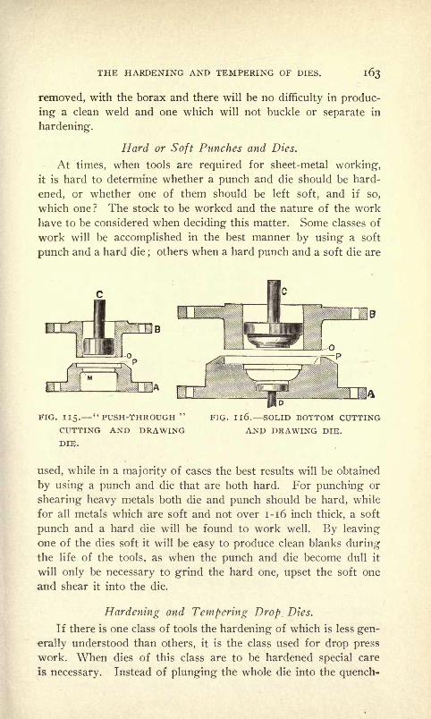
THE HARDENING AND TEMPERING OF DIES. i63
removed, with the borax and there will be no difficulty in produc-
ing a clean weld and one which will not buckle or separate in
hardening.
Hard or Soft Punches and Dies.
At times, when tools are required for sheet-metal working,it is hard to determine whether a punch and die should be hard-
ened, or whether one of them should be left soft, and if so,
which one? The stock to be worked and the nature of the work
have to be considered when deciding this matter. Some classes of
work will be accomplished in the best manner by using a soft
punch and a hard die;others when a hard punch and a soft die are
FIG. 115." PUSH-THROUGH "
CUTTING AND DRAWINGDIE.
FIG. Il6. SOLID BOTTOM CUTTING
AND DRAWING DIE.
used, while in a majority of cases the best results will be obtained
by using a punch and die that are both hard. For punching or
shearing heavy metals both die and punch should be hard, while
for all metals which are soft and not over 1-16 inch thick, a soft
punch and a hard die will be found to work well. By leaving
one of the dies soft it will be easy to produce clean blanks duringthe life of the tools, as when the punch and die become dull it
will only be necessary to grind the hard one, upset the soft one
and shear it into the die.
Hardening and Tempering Drop. Dies.
If there is one class of tools the hardening of which is less gen-
erally understood than others, it is the class used for drop press
work. When dies of this class are to be hardened special care
Is necessary. Instead of plunging the whole die into the quench-
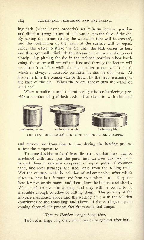
164 HARDENING, TEMPERING AND ANNEALING.
ing bath (when heated properly) set it in an inclined position
and direct a strong stream of cold water onto the face of the die.
By having the stream strong the whole die face will be covered,
and the contraction of the metal at the surface will be equal.
Allow the water to strike the die until the bath ceases to boil,
and then gradually diminish the stream and allow the die to cool
slowly. By placing the die in the inclined position when hard-
ening, the water will run off the face and thereby the bottom will
remain soft and hot while the die portion proper will be hard,
which is always a desirable condition in dies of this kind. At
the same time the temper can be drawn by the heat remaining in
the base of the die. When the colors appear turn the water on
until cool.
When a muffle is used to heat steel parts for hardening, pro-
vide a number of 3-1 6-inch rods. Put them in with the steel
Redrawing Punch. Inside Blank Holder. Redrawing Die.
FIG. 117. REDRAWING DIE WITH INSIDE BLANK HOLDER.
and remove one from time to time during the heating process
to test the temperature.
To anneal white or hard iron die parts so that they may be
machined with ease, put the parts into an iron box and packaround them a mixture composed of equal parts of common
sand, fine steel turnings and steel scale from the rolling mills.
Wet the mixture with the solution of sal-ammoniac, after which
place the box in a furnace and heat to a white heat. Keep the
heat for five or six hours, and then allow the box to cool slowly.
When cool remove the castings and they will be found to be
malleable enough to allow of cutting them. The packing of the
mixture mentioned above and the wetting of it with the solution
contributes to the annealing, and allows of the castings or parts
coming through the process free from scale and lumps.
Hoiv to Harden Large Ring Dies.
To harden large ring dies, which are to be ground after hard-
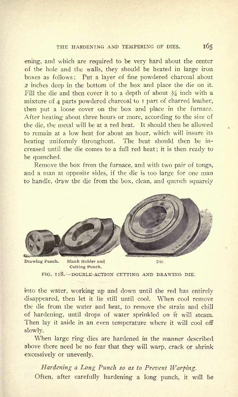
THE HARDENING AND TEMPERING OF DIES. 165
ening, and which are required to be very hard about the center
of the hole and the walls, they should be heated in large iron
boxes as follows : Put a layer of fine powdered charcoal about
2 inches deep in the bottom of the box and place the die on it.
Fill the die and then cover it to a depth of about ^4 inch with a
mixture of 4 parts powdered charcoal to I part of charred leather,
then put a loose cover on the box and place in the furnace.
After heating about three hours or more, according to the size of
the die, the metal will be at a red heat. It should then be allowed
to remain at a low heat for about an hour, which will insure its
heating uniformly throughout. The heat should then be in-
creased until the die comes to a full red heat;
it is then ready to
be quenched.Remove the box from the furnace, and with two pair of tongs,
and a man at opposite sides, if the die is too large for one manto handle, draw the die from the box, clean, and quench squarely
Drawing Punch. Blank Holder and Die.
Cutting Punch.
PIG. Il8. DOUJBLE-ACTION CUTTING AND DRAWING DIE.
into the water, working up and down until the red has entirely
disappeared, then let it lie still until cool. When cool remove
the die from the water and heat, to remove the strain and chill
of hardening, until drops of water sprinkled on it will steam.
Then lay it aside in an even temperature where it will cool off
slowly.
When large ring dies are hardened in the manner described
above there need be no fear that they will warp, crack or shrink
excessively or unevenly.
Hardening a Long Punch so as to Prevent Warping.
Often, after carefully hardening a long punch, it will be
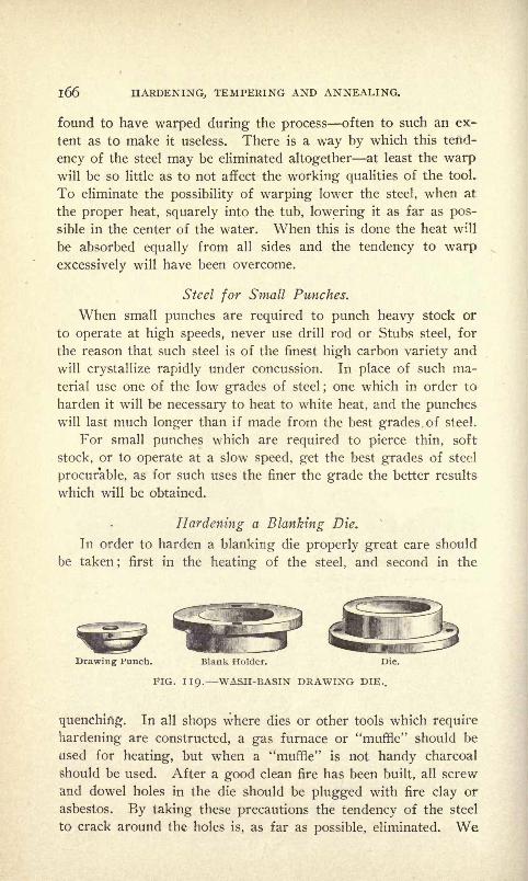
l66 HARDENING, TEMPERING AND ANNEALING.
found to have warped during the process often to such an ex-
tent as to make it useless. There is a way by which this tend-
ency of the steel may be eliminated altogether at least the warpwill be so little as to not affect the working qualities of the tool.
To eliminate the possibility of warping lower the steel, when at
the proper heat, squarely into the tub, lowering it as far as pos-
sible in the center of the water. When this is done the heat will
be absorbed equally from all sides and the tendency to warp
excessively will have been overcome.
Steel for Small Punches.
When small punches are required to punch heavy stock or
to operate at high speeds, never use drill rod or Stubs steel, for
the reason that such steel is of the finest high carbon variety and
will crystallize rapidly under concussion. In place of such ma-
terial use one of the low grades of steel; one which in order to
harden it will be necessary to heat to white heat, and the puncheswill last much longer than if made from the best grades of steel.
For small punches which are required to pierce thin, soft
stock, or to operate at a slow speed, get the best grades of steel
procurable, as for such uses the finer the grade the better results
which will be obtained.
Hardening a Blanking Die.
In order to harden a blanking die properly great care should
be taken;
first in the heating of the steel, and second in the
Drawing Punch. Blank Holder. Die.
FIG. 119. WASH-BASIN DRAWING DIE..
quenching1
. In all shops where dies or other tools which require
hardening are constructed, a gas furnace or "muffle" should be
used for heating, but when a "muffle" is not handy charcoal
should be used. After a good clean fire has been built, all screw
and dowel holes in the die should be plugged with fire clay or
asbestos. By taking these precautions the tendency of the steel
to crack around the holes is, as far as possible, eliminated. We

THE HARDENING AND TEMPERING OF DIES. l6/
now heat the die to an even cherry red, so that the entire plate
will be the same temperature; then remove it from the fire and
dip it endwise into the water (which should first be warmed
slightly to take the chill out), being careful to dip down straight,
and not to move it or shake it around as that would increase the
possibility of the die warping, or shrinking excessively. After
removing the die from the water it should be immediately
warmed. Now grind the face of the die; heat a thick piece of
cast-iron red hot, and place the die upon it;
it can then be drawn
evenly to any temper desired. By taking a piece of oil waste
and wiping the face of the die as it is heating, the different colors
will show up clear. When the color denoting the temper re-
quired appears, remove the die and allow it to cool off slowly.
Cracks in Dies Their Cause.
When a piece of tool steel in itself of no great commercial
value is worked out and finished into an intricate die the labor
cost amounting to a large sum, the steel is, of course, very valu-
able; and if cracks show after the hardening process, or the die
is spoiled, it means a great loss to the establishment.
Now in the first place, although we are apt to usually con-
found cracks with hardening, very often the trouble can be
traced to the preceding operations of annealing, forging and
finishing. Of course there is a large number of dies -spoiled
through carelessness or inexperience in hardening, but still we
believe there is as great an amount spoiled through imperfect
preceding operations or through the operator not being familiar
with the nature of the steel.
A die may be carefully heated to give the proper temperature
throughout, and may be quenched in the bath in the most ap-
proved manner, but if it is not "slightly warmed" after removingit from the hardening bath, it is liable to crack. This reheating-
may be done in a number of ways. The best way is to hold the
die over the fire until it is heated to a temperature sufficient to
cause a few drops of water to steam when sprinkled on it. The
heat will not be sufficient to make any of the temper colors
appear.
The author has been connected with one establishment where
thousands of dies were made every year, and every die was re-
heated after hardening, in the following manner: A large tank
provided with a perforated tray with means for raising and lower-
l68 HARDENING, TEMPERING AND ANNEALING.
ing it was used. The tank was filled with water to within two
inches of the top and a steam pipe was connected with it. Then
the water was kept at the boiling point, and the die directly after
hardening was placed upon the tray which was then lowered
into the bath.
We have known dies to crack while being in the forge whenthe blaze touched the die portion proper. This being broughtabout by a sudden heat and then a cold blast of air causing the
steel to expand and then suddenly contract again, at a certain
point, and as the consequent expansion and contraction in the
die does not extend over the entire surface, the charge was local
and cracks resulted.
A die made from a blank cut from a bar and machined and
worked out without annealing is liable to crack when subjected
to the hardening process, particularly if the blank is for a blank-
ing die of odd shape, as shown in Fig. 120. If annealed bar steel
is used the necessity of reannealing is also imperative as the first
annealing does not eliminate the liability of cracking.
When it is not possible to anneal the die blank before finish-
ing to size, the next best thing to do is to heat the die uniformly
throughout to a red heat, then remove it from the fire and allow
it to cool until black. It may then be reheated to the proper
temperature and hardened. In a forming die the bulky portion
has a tendency to contract away from the small portions, which
being frail, harden first and do not alter their shape, while the
bulky portion continues to contract unevenly, after the thin por-
tion becomes ridged, and cracks are apt to appear when the tool
is removed from the quenching. By heating the die to a highor red heat and then allowing it to cool to a black before the
hardening heat this uneven contraction is to a certain extent pro-
vided for.
In hardening a die the quenching of it so that the frailest por-
tion enters the bath first and hardens before the thickest por-
tion, will most invariably cause cracks to appear, as unequal con-
traction takes place and the heavy portion contracting the most,
changes shape in attempting to draw with it the frailer portions.
Another cause of cracks in dies is the use of improper means
for grinding. When a die is ground on a machine on which
no provision is made for water cooling, or where a fine wheel is
used, cracks often result, coming about through the steel being
unevenly heated during the grinding. Thus, by using a coarse

THE HARDENING AND TEMPERING OF DIES. ItX)
wheel with a free water supply this disagreeable possibility will
be eliminated.
Hardening the Walls of a Round Die.
Often, in die work, it is desired that the walls of a drawing
die, for instance, or some other part, such as the inside of a
FIG. I2O. BLANKING DIE.
hollow punch, should be hard and the remaining portion of the
piece soft. This may be accomplished by proceeding as follows :
Clamp the die or punch, as the case may be, between flanges on
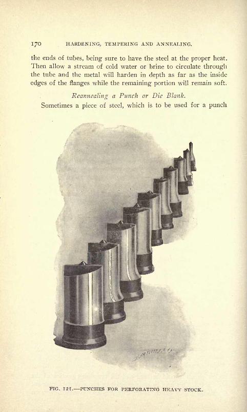
170 HARDENING, TEMPERING AND ANNEALING.
the ends of tubes, being sure to have the steel at the proper heat.
Then allow a stream of cold water or brine to circulate throughthe tube and the metal will harden in depth as far as the inside
edges of the flanges while the remaining portion will remain soft.
Reannealmg a Punch or Die Blank.
Sometimes a piece of steel, which is to be used for a punch
FIG. 121. PUNCHES FOR PERFORATING HEAVY STOCK.

THE HARDENING AND TEMPERING OF DIES. 171
or die, upon starting to machine it, proves hard, although it has
been annealed. When this is the case, never try to finish it before
reannealing it; instead, rough it down, clean out the centers, if
there are to be any, and anneal it over again. The time re-
quired to reanneal the piece of steel will be more than made upin the machining of it.
Warping of Long Punches in Hardening.
Often after carefully hardening a long punch it will be found
to have warped during the process, often to such a degree as to
make it useless. There is a way to avoid this altogether, or at
least the warp will be so slight as to not affect the efficiency of
the tool. To insure against warping, plunge the steel, when at
the proper heat, squarely into the bath, lowering as far as pos-
sible into the center of the liquid. When this is done the heat
will be absorbed equally from all sides and the tendency to warp
excessively will have been eliminated.
Hardening Very Small Punches.
When a large number of very small piercing punches are to
be hardened they should be packed in closed iron boxes and the
box heated. When all the parts have reached the proper heat
they should be entered into a bath of either oil or water, as the
nature of the work may require, through a funnel. This will in-
sure the entering of the parts vertically and prevent warping.
Another way by which small punches may be heated uniform is
by means of the lead bath. Keep the lead at the proper heat and
cover the top with powdered charcoal and coke.
Tempering Small Punches.
Almost all lar^e die shops in which any amount of hardening
and tempering are clone have discarded the method of tempering
by colors, and have adopted the more reliable method of doing it
in oil, gaging the heat by thermometer. A kettle containing
the oil is placed on the fire and heated to the right temperature
for the degree of temper desired in the work. The hardened
parts are then thrown into the liquid until drawn. By this
method there is no possibility of overdrawing, as it is impossible
for the parts to become hotter than the oil. When tempering
punches in this manner it is not necessary to brighten them be-
fore the operation, and where a lot of such work is done, it will

172 HARDENING, TEMPERING AND ANNEALING.
be accomplished much cheaper than if the old method were used ;
besides the most satisfactory results will be attained.
Hardening Fluids for Dies.
We have heard a great deal about hardening fluids, for which
it is claimed dies can be hardened better than in water or in brine.
Such fluids are composed chiefly of acids and will rot the steel,
and we should advise keeping away from them, as where it is
not possible to harden die steel in clear water or strong brine,
the steel is useless and should be dispensed with. When quench-
ing the heated steel dip down straight and don't shake it about,
but after keeping it stationary for a few seconds, move it around
slowly, keeping it vertical all the time. When the die or punchis of an intricate shape, about three inches of oil on the top of
the water will toughen it and contribute to helping the steel
retain its shape while hardening, and prevent it from warping or
cracking during the process. Lastly, immediately after harden-
ing and before grinding, the steel should be placed on the fire
and slightly warmed, to take the chill and contraction strain out
and not laid aside for a while, as we have seen dies that were laid
aside after hardening (that were intact) after a few hours, show
cracks.
Hardening Thick Round Dies.
Often round dies, which are very thick in proportion to
their diameter, contract excessively in the center during the
hardening process, often to such a degree as to make them unfit
for use. To overcome this tendency have an arrangement by
which a stream of water may be forced through the hole without
wetting the outside ; allowing the water to only come in contact
with the inside of the die. By doing this the walls of the die will
be hard while the outside will remain soft, as when the temperis drawn the hole will remain straight and true. In shops where
grinding facilities are not at hand this method will work ex-
cellently. If possible use strong brine for the hardening fluid.
Hardening Poor Die Steel
Quite frequently in making dies we run across a piece of steel
which after working will not respond satisfactorily to the usual
hardening process. When this occurs prepare a solution com-
posed of two handfuls of common salt and one ounce of corrosive
sublimate. to about six quarts of water and when the steel has

THE HARDENING AND TEMPERING OF DIES. 173
reached a good red heat plunge into the bath. The corrosive
sublimate gives toughness to the steel and the salt hardens. This
solution is deadly poison ;exercise care in using it.
Tempering a Combination Cutting and Drawing Punch.
After the face of the punch has been slightly sheared, and
the edges of the drawing die slightly rounded and highly pol-
ished, the punch is hardened and then drawn by laying it alter-
nately on each of its four sides on a hot plate, tempering the
cutting edges to a dark blue and leaving the inside or drawingdie portion as hard as possible. When finishing the blanking
portion of the punch, care has to be taken to do it so that the
drawing portion will be perfectly central.
Hardening and Tempering a Split Gang Punch.
The best way to harden and temper a split gang punch is bythe following method : It should first be heated and hardened in
clear oil, dipping it from the back, and thus preventing as far
as possible the legs from crawling in toward each other because
of the channel between them. By dipping from the back this
will be overcome, as by the time the cutting face is immersed
the back will be hard and set. It should then be polished and
tempered by drawing from the back to a dark blue to within }/\
inch of the cutting faces and quenched when those portions are a
dark straw color.
Hardening and Tempering Large "Blanking" or "Cutting" Dies.
Large "blanking" or "cutting" dies of the type shown in
Figs. 122 to 127 require considerable skill and experience to
harden and temper correctly. They should be carefully heated
and then quenched into a large tank of water and when cold
warmed on the fire to take the chill and strain out.
Cutting dies consist of an upper "male" die or "punch," and
the lower, or "female" die. They may be made in almost anysize and shape for cutting out flat blanks in tin, iron, steel, alumi-
nium, brass, copper, zinc, silver, paper, leather, cloth, etc. Ordi-
narily, the lower die is hardened and tempered to a degree best
suited for the work, while the punch is left comparatively soft,
so that it can be "hammered" up when worn. Sometimes, as in
the case of playing-card dies, it is preferable to reverse this and
make the punch hard, leaving the die soft. Circumstances de-

174 HARDENING, TEMPERING AND ANNEALING.
termine whether any or how much "shear" should be given to the
cutting edge. For ordinary work in tin, brass, etc., a moderate
amount of shear is desirable. These dies require to be made with
the utmost care, of materials specially adapted for the purpose,
and by experienced and skillful workmen. Ordinarily, the steel
cutting rings are welded to wrought-iron plates, after which they
FIG. 125. FIG. 127. DIE.
are hardened, carefully tempered and ground on special machin-
ery. In some cases it is preferable to fasten the steel dies in
cast-iron chucks or die-beds by means of keys or screws. This
applies more particularly to small dies. For cutting thick iron,
steel, brass, and other heavy metals both the die and punch should
be hard and provided with strippers.

CHAPTER X.
FORGING AND WELDING TO ACCOMPLISH SATISFACTORY RESULTS
IN THE FORGING OF STEEL AND IRON DROP FORGING.
Welding Heats.
In the welding of steel to steer or steel to iron without injur-
ing the quality of the material, the process involved is one in
which great care, judgment and skill are necessary, particularly
in dealing with the degrees of heat. Because of its greater flexi-
bility the welding heat of steel should be lower than that of iron
and thus the more flexible the steel the harder it is to weld.
Mild steel can be welded much more easily than high carbon or
tool steel. Ordinary cast steel such as double shear steel, con-
taining as it does a smaller proportion of carbon than "tool
steel," may be easily welded, as its texture, which is very fibrous,
is partly restored through hammering or rolling. Thus for all
edge tools for wood this steel will give good results as it will
carry a very keen cutting edge.
A Good Welding Flux for Steel
A good flux for welding steel is sal-ammoniac and borax.
The borax of commerce as sold by chemists is composed of a
very large proportion of water, and in order to use this, it should
be put into an iron or other suitable vessel and boiled over the
fire until all the water is expelled, after which it should be groundto a powder before it is used. When it is desired to mix sal-
ammoniac with borax the proportions are about 16 parts borax to
i of sal-ammoniac. In heating a piece of steel for forging it
should be placed in the center of a close hollow fire and the wind
put on very sparingly, so as to allow the mass to heat equally
through and through. If, on the other hand, it is put into the fire
and the blast turned on full the outside of the metal will become
red hot before the center; therefore the expansion of the outside
away from the center will cause internal strains, which will not
be visible until the tool is hardened, and then the hardener will be
blamed.

176 HARDENING, TEMPERING AND ANNEALING.
Heating Steel for Forging.
A great many smiths say that steel should not be heated above
a cherry red;but the best way is to heat the steel to as high a
heat as it will stand with safety, and draw down under steam
hammer, if there is one handy. Then the whole mass will draw
down in the center as well as around the outside, where, on the
contrary, by heating to a cherry red one would only be drawingthe outside away from the center, which would show fracture
when cooled. We do not mean that the steel should be heated
high when the tool is nearly finished;then the cherry red heat will
do, being also careful not to hammer after the red has disappeared,
but put it back in the fire and heat as evenly as possible. Sulphuris the greatest enemy to contend with in the heating of steel.
To fully illustrate the effects, heat a piece of cast steel almost to
the scintillating heat, and by holding a piece of sulphur against
it, it will drop to the floor, the same as a piece of sealing waxwould do with a match. A man who is forging and welding iron
should never be asked by the foreman to dress a tool, as that
man is blind to the colors of steel which reveal themselves in the
tempering.
Steel for Tools Which Require to be Forged.
In purchasing tool steel for the various kinds of tools that are
used in metal working it is best to state to the steel maker what
kind of tools the steel is required for, as steel that is suitable for
cold chisels is too low in carbon for lathe and planer tools. Highcarbon steel cools far quicker under the blows of the hammerthan low, and the scales that fall from the former are small and
silky while the latter are large.
The amount of working one will get out of a tool which has
been properly forged, tempered and ground is unlimited. It is a
bad economy to buy cheap steel for tools of any kind. It only
results in worry and vexation and poor work.
High Grade Steel Forgings in America.
Few people are probably aware of the important change that
has taken place in machine construction in this country as a
direct result of the improvements in the manufacture and forgingof crucible cast steel, first introduced by the Bethlehem Steel Com-
pany, Pennsylvania, U. S. A. Without these improvements the
large power units now used in the electric generating stations

FORGING AND WELDING. 177
would have been impossible, for no forgings could have been
obtained that would have been able to sustain the tremendous
strains of such machinery. When steel forgings were first em-
ployed for large work they were generally considered inferior to
iron forgings, because, as is well known, steel is not as easily
forged as iron and is more easily injured in the process, while'
the methods used in forging were not adapted to the requirementsof the new material. The improvements in the manufacture of
steel came through the efforts of the government to obtain steel
suitable for large guns and the parts of marine engines, which,
according to law, had to be built in this country, and of Ameri-
can material. A brief history of how the change of iron forgingsto high-grade steel forgings came about, and the manner in which
hollow shafts are forged, is given in the following and is taken
from a paper by Mr. H. F. J. Porter, read before the 1902 meet-
ing of the Engine Builders' Association :
At the time George H. Corliss built his Centennial engine he
had his own smithshop in which his shafts and other engine forg-
ings were built up out of small fagots of wrought iron. This
was about the time when steel began to encroach upon iron In the
trades. Before this time wrought iron was a staple article in the
market. The quality of this material, coming from the rolling
mills, was very high, demands for high grades having broughtabout methods of precaution which supplied the trades with ex-
tra refined iron, very free from slag and dirt. The small forges
sparsely scattered about the country were equipped with ham-mers of ten tons falling weight with top steam, sufficient in capa-
city to thoroughly work and weld together the few fagots of
iron which were required to build up the moderate sized forgingswhich the various industries demanded. When steel made its ap-
pearance, however, manufacturers generally began to appreciate
the fact that the market contained a new material, stronger and
more reliable than wrought iron. Desirous of having the forged
parts of their mechanisms smaller and lighter, they attempted at
once to obtain forgings made of this metal. Had the forgersmade proper efforts to acquaint themselves with the nature of
the new material before attempting to supply it, a very different
condition of affairs would have come about, not only in the forg-
ing industry, but in the steel industry at large, which resulted
from the first unintelligent effort at production. At the meet-
ing of the Railway Master Mechanics and Master Car Builders,
178 HARDENING, TEMPERING AND ANNEALING.
at Old Point Comfort, in 1899, Captain (now Admiral) RobleyD. Evans delivered an address in which he said :
"In 1882 I had the good fortune to be a member of what is
known as the first advisory board for rebuilding the navy. It
was an awfully hot summer, and fifteen of us, rather impatient in
spirit, got together in Washington, presided over by Admiral
John Rodgers. When we looked the field over, we found that
we had no navy at all;we were hopelessly behind the age, and it
seemed hardly worth while to rebuild our navy. I shall never
forget as long as I live the trouble I caused in that small conven-
tion by proposing that we should build steel ships. I was the
original steel man, and when I proposed that all ships in future
should be built of steel, Admiral Rodgers adjourned the board
for three weeks to prevent a fight."
Now the animus referred to by Admiral Evans was induced
by the fact that forgings which were being supplied at this time
were of just such a type as might be expected to be produced by
men who had not acquainted themselves with the requirements of
the new material. While some were excellent in every way, others
were different in strength, or contained concealed cavities and
were unreliable in general. The supplies of material running so ir-
regular in quality reflected unfavorably upon the steel industry at
large and developed a prejudice against steel generally, from
which it has scarcely recovered in the minds of many users
of forgings, even at the present day. It was fortunate for the
country that the advisory board referred to contained as stalwart
a champion of steel as Admiral Evans, for after they had visited
the various ordnance works abroad and had seen steel worked
properly, they returned home and recommended to the Secretary
of the Navy Mr. Tracy, that by all means the new navy should
be built of this metal, and as there were no properly equipped
steel forges in this country, one would have to be built .to furnish
the necessary armor, guns and engine forgings required in the
construction of modern naval war vessels. Meanwhile, this board
had overcome, through the good offices of its secretary, the
personal objections heretofore existing on the part of Sir Joseph
Whitworth to the use of his special steel casting and forging
processes elsewhere than in his own works, which were con-
sidered foremost in the manufacturing of ordnance. Without
entering into the details which accompanied the immediate estab-
rtaent in this country of the great ordnance works of the

FORGING AND WELDING. 179
Bethlehem Steel Company, it is sufficient to say that in their
equipment not only were special appliances in use in this Englishworks duplicated, but their size was doubled. A contract was
also entered into at the same time by which the great works of
Schneider & Co., of Le Creusot, France, which stood first amongthe makers of armor plate, were also duplicated at the Bethle-
hem plant. Thus there arose in this country a forging plant at
once larger and superior to any in the world.
During the years this plant was being erected there were
many engineers who, appreciating the superior advantages of steel
forgings when properly produced over those made of wrought
iron, systematically sent abroad for their steel forgings. It was not
until 1889 that the country obtained its first high-grade steel
commercial forgings from the Bethlehem works. These had
been gladly specified by the engineers above mentioned who were
impatiently waiting to get their steel forgings nearer home than
in Europe. Machine and tool builders of this country were thus
made acquainted for the first time with steel forgings intelli-
gently produced. There are to this day many users of steel forg-
ings who, not having carefully investigated the methods con-
sidered necessary to produce them, think that a steel forgingis made by merely hammering a rolled steel billet to the form
required ; and such as order their forgings without specifying
more definitely the grade called for by the special service to
which the forging is to be submitted may get a forging of that
type. The forging industry has grown from the blacksmith
shop, a once familiar adjunct to an engine works, and has become
a specialty ; and a modern steel forge is not now thought com-
plete unless it melts its own raw material and converts it into
the finished product under the supervision of chemists, metallurg-
ists, physicists and microscopists.
Hozv Hollow Shafts Are Forged.
There are two ways of making a forging hollow. The ordi-
nary way of getting rid of the center of a forging is simply to
bore it out. After boring, it is tempered and thus jhe strength is
restored which was taken away with the material which was
in the center.
Another way of getting rid of the center of large forgings
is to forge them hollow. A person who has not considered the
subject carefully would naturally think that the first thing to do j

l8o HARDENING, TEMPERING AND ANNEALING.
making a hollow forging would be to cast a hollow ingot. It has
been mentioned that there were various defects which occur in
ingots, the most serious of which are "segregation" and "piping"and that it is in the center and upper portion where those defects
occur. If an ingot were to be cast hollow, a solid core of fire-
brick or similar material would replace the center metal, and
instead of one on the outside there would be two cooling surfaces,
one on the outside and one around the core, and the position of
the last cooling would be transferred to an annular ring, midwaybetween these surfaces, where the "piping" and "segregation"
would collect. This would not be satisfactory, because the metal
there is what must be depended upon for the strength of the
hollow forging. It is necessary, therefore, to collect the "piping"
and "segregation" in the center and the top, where the metal has
been added to the original ingot for the purpose.
Then having cut off the top and bored out the center, the
"piping" and "segregation" are entirely eliminated and what is
left is as sound and homogeneous a piece of steel as can be
obtained.
After the hole has been bored in the ingot, the next process is
to re-heat it, and, as before explained, this process is not as de-
licate a one as if the ingot were solid. The heat affects the center
equally with the interior and they expand together and the
danger of cracking is not incurred. When the ingot is re-
heated a steel mandrel is put through its hollow center, and sub-
jecting the two to hydraulic pressure the metal is forced down
and out over the mandrel. Thus an internal anvil is practically
inserted into the forging and there is, therefore, really much less
than one-half the amount of metal to work on than if the piece
were solid.
When the work of shaping is completed the forging is re-
heated to the proper temperature and then either annealed in the
usual manner or plunged into a tempering bath of oil or brine, to
set the fine grain permanently that has been established by the re-
heating. A mild annealing follows to relieve any surface or other
strains that may have been occasioned by the rapid cooling.
Hollow forcings oil-tempered and annealed are considered the
best grade of forgings made, and any forgings made otherwise,
although they may be suitable for the service to which they maybe applied, cannot be looked upon in any other manner than as
of an inferior grade.
FORGING AND WELDING. l8l
That steel forgings of such high grade were being manufac-
tured for commercial purposes in this country was first broughtto the attention of manufacturers generally at the World's Fair
in Chicago. Here were exhibited stationary engine forgings
which compared favorably with those sent over by European
forges. The Ferris wheel shaft, 45 feet long and 32 inches out-
side diameter, with a 1 6-inch hole through it, represented the
largest made up to that time. The soliciting of orders for such
forgings, however, at once aroused the latent prejudice still ex-
isting against steel forgings, and the prices demanded being some-
what in excess of those which wrought iron or ordinary steel
forgings could be obtained for, prevented at first the very rapid
introduction of this product into the commercial field.
Difficulties Encountered in Introducing High-Grade Forgings.
It hardly seemed necessary to explain to an engineer or anyone authorized to purchase, and therefore presumably competent,
that if he wanted material to sustain severe usage in the nature of
alternating stresses, to which all forgings are subjected, he should
select a material possessing a very high elastic limit. And yet it
was not unusual to find that those very people preferred to use
wrought iron for their engine crosshead and crank pins and
shafts in preference to steel, because, as they said, "steel being
crystalline is brittle and snaps off suddenly under such services
as that under consideration, while iron having fiber, is tougherand yields before breaking." Most of these men know better,
but had not given the subject sufficient thought, or they would
have perceived that their statements were not consistent. Theysaid that the steel connecting rods they had tried had broken off
short without any warning, while rods made of wrought iron had
simply bent up, and after having been straightened out were re-
placed as good as new.
These people did not stop to think that a steel rod that broke
off had done so at its ultimate strength, or under a stress of from
80,000 to 90,000 pounds per square inch, whereas the iron rod
which had doubled up had done so at its yielding point of 25,000to 30,000 pounds per square inch. In other words, their engineswith wrought iron rods were failing all over the country under
loads about one-third what they were standing up to when sup-
plied with steel rods, yet the men were blaming the steel for help-
ing them out of their troubles.

l82 HARDENING, TEMPERING AND ANNEALING.
Then again they complained that steel shafts and crank pins
heated up, while wrought iron ran cool. When it was proved to
them that laboratory experiments showed the coefficient of friction
of these metals to be the same, and that any difference in heating-
was caused by local circumstances, such as poor lubrication, ex-
cessive pressure, etc., they said they did not care for laboratory
experiments. They had an engine in one place with a steel shaft
that never would run cool, while another with a wrought-ironshaft had never given any trouble, and they were passing judg-ment on their own experience. Persistent exposure of these fal-
lacies gradually brought about a change in sentiment.
"Cold Crystallization" Does Not Occur.
It took a long time to persuade people who had seen broken
fcrgings which showed a coarse crystalline section that the
metal had not crystallized from shock or vibration in service,
but had been forged in such a manner that the crystallized
condition of the ingot from which the forging had been
made had not been changed by the forging process or by
subsequent heat treatment. And these are the people even nowwho consider themselves conservative, who would rather havetheir forgings made of a mild steel which is weak, than of a high-carbon steel which is strong, simply because the old ideas are not
yet eradicated from their minds. Tests were made at the gov-ernment testing bureau at Watertown by rapidly bending bars
forward and backward within their elastic limit, with the follow-
ing results, and these have given engineers an idea of the com-
parative endurance of wrought iron, steel and nickel steel, msuch service as that to which crank pins, shafts, etc., are subject.
Tests of Steel Under Repeated Stresses.
Under a Fiber Stress of 40,000 Pounds per Square Inch.
Wrought iron breaks after 50,000 alternations of stress.
.15 p. c. carbon steel "170,000
-25 P- c."
229,000
-35 P- c. 317,000
-45 P- c. "976.000
" "
3>4 P- c. nickel steel, carbon .25 to .30 p. c., 1,850,000 alternations of stress.
4/2 P- c. .25 to .30 p. c., 2,360,000
51/? P- c.
".25 to .30 p. c., 4,370,000
"
Charcoal.
The best qualities of charcoal are made from oak, maple, beech

FORGING AND WELDING. 183
and chestnut. Between 5 and 17 per cent of coal will be ob-
tained when the wood has been properly burned. A bushel of
coal from hardwood weighs from 29 to 31 pounds and from
pine 28 to 30 pounds.
Welding Powder for Iron and Steel. For welding iron and
steel a composition has lately been patented in Belgium, consisting
of iron filings, 40 parts ; borax, 20 parts ;balsam of copaiba or
some other resinous oil, 2 parts, and sal-ammoniac, 3 parts. Theyare mixed, heated and pulverized. The process of welding is
much the same as usual. The surfaces to be welded are powderedwith the composition and then brought to a cherry red heat, at
which the powder melts, when the portions to be united are taken
from the fire and joined. If the pieces to be welded are too
large to be introduced at the same time into the forge, one can
be first heated with the welding powder to a cherry red heat and
then others afterward to a white heat, after which the welding
may be effected.
To Make Edge-Tools from Cast-Steel and Iron. This method
consists in fixing a clean piece of wrought iron, brought to a
welding heat, in the center of the mould, then pouring in melted
steel, so as to entirely envelop the iron, and then forging the
mass into the shape required.
To Weld Cast-Iron.
Take 3 parts of good class white sand, refined solution fost-
ering and rock salt of each i part ;heat the pieces to be welded
in a charcoal fire, occasionally taking out and dipping into the
composition, until they are of a proper heat to weld. Thentake immediately to the anvil and weld together. If done care-
fully by one who understands welding iron, there will be a good
strong weld.
Welding Composition for Cast-Steel. Take borax, 10 parts;
sal-ammoniac, i part ; grind or pound them roughly together, then
fuse them in a metal pot over a clear fire, taking care to con-
tinue the heat until the spume has disappeared from the surface.
When the liquid appears clear, the composition is ready to
be poured out to cool and concrete ; afterward, being groundto a fine powder, it is ready for use. To use this composition,
the steel to be welded is first raised to a bright yellow heat,
it is then dipped into the welding powder, and again placed in

184 HARDENING, TEMPERING AND ANNEALING.
the fire until it attains the same degree of heat as before; it is
then ready to be placed under the hammer.
How to Restore Overheated Steel.
A number of receipts for compositions which will restore over-
heated steel are given in the following:
To Restore Overheated Cast-Steel. Take i~y2 pounds borax,
1/2 pound sal-ammoniac, i/4 pound prussiate potash, i ounce
rosin. Pound the above fine, add a gill each of water and alcohol.
Put in an iron kettle, and boil until it .becomes paste. Do not boil
too long or it will become hard on cooling.
To Restore Overheated Steel. Borax 3 pounds ; sal-ammon-
iac, i pound ; prussiate potash, y2 pound ; alcohol, i gill ;soft
water, i pint. Put into an iron pan and hold over a slow fire until
it comes to a slow boil and until the liquid matter evaporates ;be
careful to stir it well from the bottom and let it boil slow. This
receipt is very valuable; no matter how badly the steel is over-
heated it will restore and make it as durable as ever.
To Restore Overheated Steel and Improve Poor Steel.
Borax, 3 ounces; sal-ammoniac, 8 ounces
; prussiate of potash,
3 ounces; blue clay, 2 ounces; rosin, ii/> pounds; water, i gill;
alcohol, i gill. Put all over a slow fire;let it simmer until it dries
to a powder. Heat the steel not above a cherry red; dip into this
powder and afterwards hammer.
Composition to Toughen Steel. Rosin 2% pounds ;tallow 2i/2
pounds; pitch i 1/^ pounds. Melt together and apply to the steel
while hot.
Pointer.
Rosin on the blacksmith's forge improves and toughens steel.
When the tool is hot, dip it into the rosin, then hammer.
To Weld Buggy Springs.
To weld buggy springs first scarf one piece of spring, and
then weld onto it a piece of spring cut off about three-quarters
of an inch longer than the first;heat and upset until one-quarter
thicker at end than spring scarf. Now upset the other piece
until as near thickness of first piece as possible ; scarf and weld.
Leave a trifle heavier at weld, and if the work has been done
properly the weld can be warranted not to break. Use a 41/2
pound hammer in making this weld, and keep at it until finished.
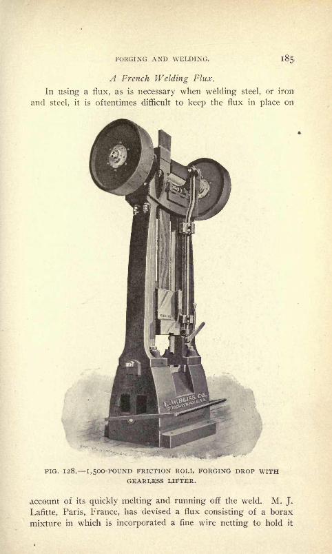
FORGING AND WELDING.
A French Welding Flux.
In using a flux, as is necessary when welding steel, or iron
and steel, it is oftentimes difficult to keep the flux in place on
FIG. 128. 1,500-POUND FRICTION ROLL, FORGING DROP WITHGEARLESS LIFTER.
account of its quickly melting and running off the weld. M. J.
Lafitte, Paris, France, has devised a flux consisting of a borax
mixture in which is incorporated a fine wire netting to hold it
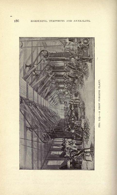
i86 HARDENING, TEMPERING AND ANNEALING.

FORGING AND WELDING. 187
together. It is rolled out in thin sheets and divided into squareswhich are easily broken apart for use. Tests of steel specimenswelded in the French government works show a remarkably
high efficiency of the welds. This is due to the high protective
power of the flux which prevents the formation of oxide on the
surface of the welds.
Compound for Welding Steel. The following compositionhas in a number of cases proved superior to borax for weldingsteel : Mix coarsely powdered borax with a thin paste of prussi-
ate blue; then let it dry.
Fluxes for Soldering and Welding.
For iron or steel, borax or sal-ammoniac;tinned iron, rosin or
chloride of zinc; copper and brass, sal-ammoniac or chloride zinc ;
zinc, chloride of zinc; lead, tallow or rosin
;lead and tin pipes,
rosin and sweet oil.
Substitute for Borax in Welding.
Copperas, 2 ounces; saltpeter, i ounce
;common salt, 6 ounces ;
black oxide of manganese, i ounce; prussiate of potash, I ounce.
All pulverized and mixed with 3 pounds good welding sand.
High carbon steel can be welded with this at a lower heat
than is required with borax.
Drop-Forgings.
Drop forging is the art of forging with drop hammers and
may be designated as "machine blacksmithing." The inception of
the art dates back to about 1853 when Colonel Samuel Colt
adopted drop-hammers to make parts for firearms. The ma-
chines, processes and tools used in the art have since been greatly
improved and the products of the drop forging industry are now
used in a majority of the mechanical arts. Figs. 130 to 140
illustrate parts produced by drop forging.
The dies used for making drop-forgings are made in two
parts. One part (the upper) is fastened in the ram or hammer
of the drop, which moves vertically between two uprights or guides
and is raised by means of friction rolls controlled by the operator.
The other part of the die (the lower) is fixed in the anvil or
base of the hammer. The ram raises until released, when it falls
instantly,, striking with the upper die the heated bar of metal
placed on the bottom die and forcing it into impressions in both
dies. By a series of such blows the complete article is formed.

188 HARDENING, TEMPERING AND ANNEALING.
An idea of the extensive use to which drop-forgings have
been put may be gained from the fact that J. H. Williams &Co., of Brooklyn, N. Y., a company devoted exclusively to the
making of drop-forgings, started in 1889 w^ a forging plant of
three drop-hammers, and it now consists of forty-three drop-
hammers, with trip-hammers, steam hammers, upsetting ma-
chines and other apparatus.
The necessary dies used to produce drop-forging of special
shapes and sizes are usually made from a drawing or model, pre-
ferably the latter as it facilitates designing the dies and allows
FIG. 130. DROP-FORGED CRANK SHAFTS.
of figuring the cost of the tools much easier than could be done
from a drawing.In making drop-forging dies the die sinker must know whether
the drawing and model show finished or forging size; he needs
also to know the allowance desired in machining. It is usual
to add 1-32 inch on each surface to be machined unless the piece
is to be finished by grinding or polishing only, in which case i-ioo
inch is allowed;surfaces not to be machined or ground are made
close to size. Forgings vary slightly in thickness say from
i-ioo inch to 1-32 inch depending on their shape and the ma-
terial used. They can, however, be made to gage by a re-striking
operation ;this operation requires separate dies and entails addi-
tional expense.

FORGING AND WELDING. 189
FIG. 131. DROP-FORGED WRENCHES.

190 HARDENING, TEMPERING AND ANNEALING.
In addition to forging dies, the cost and endurance of which
depend upon the work required of them, trimming dies are neces-
FIG. 132. SPECTAI, DROP-FORCINGS.
FIG. 133. SPECIAL DROP-FORGING.
sary to remove the surplus metal thrown out between the forg-
ing dies in working.Before using the finished set of dies for forging, a lead proof
is struck up which is submitted to the customer. The proof often
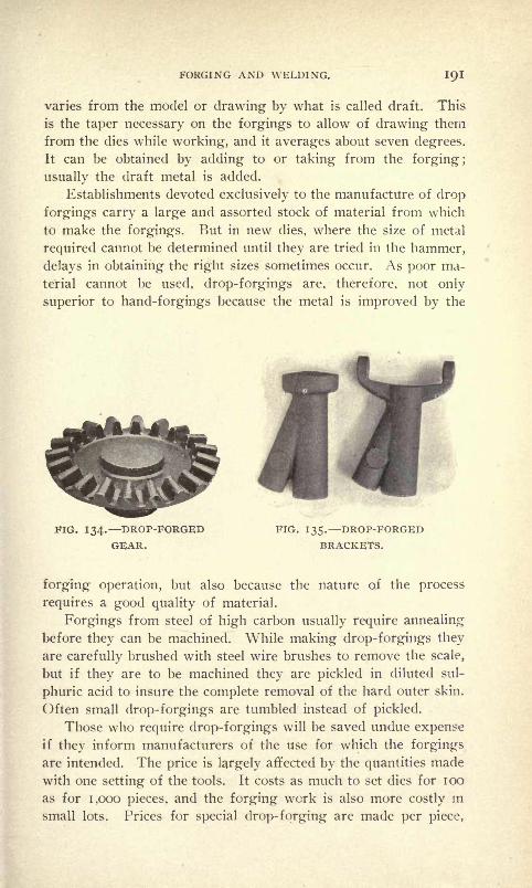
FORGING AND WELDING. IQI
varies from the model or drawing by what is called draft. This
is the taper necessary on the forgings to allow of drawing them
from the dies while working, and it averages about seven degrees.
It can be obtained by adding to or taking from the forging ;
usually the draft metal is added.
Establishments devoted exclusively to the manufacture of drop
forgings carry a large and assorted stock of material from which
to make the forgings. But in new dies, where the size of metal
required cannot be determined until they are tried in the hammer,
delays in obtaining the right sizes sometimes occur. As poor ma-
terial cannot be used, drop-forgings are, therefore, not only
superior to hand-forgings because the metal is improved by the
FIG. 134. DROP-FORGED FIG. 135. DROP-FORGED
GEAR. BRACKETS.
forging operation, but also because the nature of the process
requires a good quality of material.
Forgings from steel of high carbon usually require annealing
before they can be machined. While making drop-forgings they
are carefully brushed with steel wire brushes to remove the scale,
but if they are to be machined they are pickled in diluted sul-
phuric acid to insure the complete removal of the hard outer skin.
Often small drop-forgings are tumbled instead of pickled.
Those who require drop-forgings will be saved undue expenseif they inform manufacturers of the use for which the forgings
are intended. The price is largely affected by the quantities made
with one setting of the tools. It costs as much to set dies for 100
as for 1,000 pieces, and the forging work is also more costly in
small lots. Prices for special drop-forging are made per piece,

10,2 HARDENING, TEMPERING AND ANNEALING.
not per pound, and vary with the nature of the work, the material
used and the quantity taken.
The cheapest drop-forgings in the long run are those most uni-
form in size and quality and close to finish dimensions, thus sav-
ing labor, time, tools and money.
Directions for Setting up Forging Drop-Hammers.It is very important to have a good foundation, and we recom-
mend as the cheapest and best, when it can be obtained, a log
large enough in diameter at the butt end for the drop to stand
on, and long enough to enter the ground six or eight feet.
FIG. 136. SPECIAL DROP- FIG. I 37. DROP FORGEDFORCINGS. BRACKET.
First dig a hole one foot deeper than is necessary to receive the
log, and large enough to leave a space of about one foot all
around it. Before the log is put into the hole, fill the bottom with
grout one foot deep ; then, after placing the log in the hole so that
it will stand perpendicular, grout it nearly to the top of the
ground.For light drops, it will do very well to put a large flat stone
under the bottom of the log and fill it with earth, well stampeddown. Now adze the top of the log level ; then make a depres-
sion in the center of the surface, about six inches square and two
inches deep, with a groove about one inch wide leading to the

FORGING AND WELDING. 193
edge of the block, to allow the scales and dirt to pass off, and
not to get under the drop to make it rock or it will be unsteady.
When, because of the size of the drop, or for other reasons, a log
cannot be obtained large enough to put it on, take numbers, say
one foot square, and bolt enough of them together to make it of
suitable size, when set up on end to receive the drop. Grout, and
fill in, in the same manner as for the log. Chestnut and oak are
the best.
For forging drops with hammers weighing 1,000 to 2,000
pounds, some manufacturers build a masonry foundation 8 to 12
feet square at the base, tapering to the size of anvil shape at the
top, and 10 to 14 feet deep, with about 4 feet in height of oak
FIG. 139. DROP-FORGEDYOKE.
FIG. 138. DROP-FORGEDHOOK.
FIG. 140. DROP-FORGEDSHAFT BRACKET.
timbers at the top bolted together on end. The hole around this
foundation is then filled with .grouting. If only a rock or stone
foundation can be had, place about one-half inch of sheet rubber
or rubber belting under the bottom of the drop. There is danger
of getting a foundation too solid for a drop. There should be
some elasticity, and when set on a log or timber the desired
effect is obtained ;and when placed upon stone the rubber belting
is sufficient. A suitable foundation having now been obtained,
and the drop fastened to the same on a line with a shaft that is
to drive it, brace the drop at the top by rods, one end of which
can be secured to the building, and the other to the lifter, in
holes provided for that purpose. The belts must run back awayfrom the operator.

194 HARDENING, TEMPERING AND ANNEALING.
Government Use of Nickel Steel for Forgings.
With a view to their utilization in the various mechanical de-
partments of the government of the United States, the Bureau of
Steam Engineering has undertaken extensive experiments with
various metals. One result already is the adoption of nickel steel for
forgings and other parts of steam engines. It is contended that
the principal advantage of nickel steel over ordinary carbon steel
for forgings lies in the relation which the elastic limit bears to
the tensile strength, the former being in a sense the true strength
of the metal. The elastic limit of nickel steel is much higher
than that of carbon steel of the same tensile strength and elonga-
tion, very often 30 per cent higher and in some cases as much
as 50 per cent higher. The principal drawback to the commer-
cial use of nickel steel has been the first cost of producing it,
which in many cases is higher than the cost of ordinary. finished
forgings.
A decided virtue of nickel steel, according to government
report, is the facility with which a low carbon steel will harden,
it being the practice after a forging is forged and rough ma-
chined, to heat it and quench it in oil, which hardens it very
much; afterward the forging is submitted to an annealing pro-
cess which removes any strains set up in the metal by the sudden
cooling which it receives. Nickel steel, after the first cost of
production, is not much more expensive to forge than any carbon
steel that runs over .40 per cent carbon, and about the same care
is necessary in heating and forging as is required by a high car-
bon steel.
CHAPTER XL
MISCELLANEOUS METHODS, PROCESSES, KINKS, POINTS AND TABLES
FOR USE IN METAL WORKING.
Increasing the Size of a Reamer When Worn.
To increase a reamer to size when w'orn, burnish the face of
each tooth with a hardened burnisher, which can be made from a
three-cornered file nicely polished on the corners. This will in-
crease the size from 2 to 10 thousandths in diameter. Then hone
back to the required size.
To make a tap or reamer cut larger than itself, put a piece
of waste in one flute, enough to crowd it over and cut out on one
side only. In larger sizes (i~y2 inch or over) put a strip of tin
on one side and let it follow the tap through.
To Case-Harden Cast-Iron.
Heat to a red heat, roll in a composition consisting of equal
parts of prussate of potash, sal-ammoniac and saltpeter, pulver-
ized and thoroughly mixed. Plunge while yet hot into a bath con-
taining 2 ounces of prussate of potash and 2 ounces of sal-am-
moniac to each gallon of cold water.
Rules for Calculating Speed.
The diameter of driven given to find its number of revolu-
tions :
Rule. Multiply the diameter of the driver by its number of
revolutions and divide the product by the diameter of the driven.
The quotient will be the number of revolutions of the driven.
The diameter and revolutions of the driver being given to find
the diameter of the driven that shall make any number of revolu-
tions :
Rule. Multiply the diameter of the driver by its number of
revolutions and divide the nroduct by the number of required rev-
olutions of the driven. The nuotient will be its diameter.
To ascertain the size of millevs for given speeds :
Rule. Multiply all the diameters of the drivers together and
all the diameters of driven together; divide the drivers by the

196 HARDENING, TEMPERING AND ANNEALING.
driven. Multiply the answer by the known number of revolu-
tions of main shaft.
Improved Soldering or Tinning Acid.
Muriatic acid i pound; put into it all the zinc it will dissolve
and i ounce of sal-ammoniac, then it is ready for use.
Lubricant for Water Cuts.
Strong sal soda water cr soap water is much better than clear
water to use where water cuts are being taken, either on lathe or
planer.
Babbitting.
Put a piece of rosin the size of a walnut into your Babbitt ;
stir thoroughly, then skim. It makes poor Babbitt run better,
and improves it. Babbitt heated just hot enough to light a pine
stick will run in places with the rosin in, where, without it, it
would not. It is also claimed that rosin will prevent blowing
when pouring in damp boxes.
Laying Out Work.
In laying out work on planed or smooth surfaces of steel or
iron, use blue vitriol and water on the surface. This will copper-
over the surface nicely, so that all lines will show plainly. If on
oily surfaces, add a little oil of vitriol;this will eat the oil off
and leave a nicely coppered surface.
Lubricant for Working Aluminum.
Use kerosene oil (coal oil) for drilling or turning aluminum.
To Prevent Rust.
To prevent rust on tools, use vaseline, to which a small
amount of powdered gum camphor has been added;heat together
over a slow fire.
Lubricant for Drilling Hard Steel.
Use turpentine instead cf oil when drilling hard steel, saw
plates, etc. It will drill readily when you could not touch it with
oil.
Coppering Polished Steel Surfaces.
To copper the surface of iron or steel wire, have the wire per-
fectly clean, then wash with the following solution, when it will

MISCELLANEOUS METHODS, TABLES, ETC. IQ7
present at once a coppered surface: Rain water, 3 pounds; sul-
phate of copper, i pound.
To Blue Steel Without Heating.
To blue steel without heating, apply nitric acid;then wipe off
the acid, clean, oil and burnish.
To Remove Scale from Steel.
Scale may be removed from steel articles by pickling in water
with a little sulphuric acid in it,, and wHhen the scale is loosened,
brushing it with sand and stiff brush.
To Distinguish Wrought and Cast-Iron from Steel.
Elsiner produces a bright surface by polishing or filing, and
applies a drop of nitric acid, which is allowed to remain there
for one or two minutes, and then washed off with water. The
spot will look a pale ashy gray on wrought-iron, a brownish black
on steel, a deep black on cast-iron. It is the carbon present in var-
ious proportions which produces the difference in appearance.
Anti-Friction Alloy for Journal Boxes.
Zinc, 17 parts; copper, I part; antimony, y2 part.
This possesses unsurpassable anti-friction qualities and does
not require the protection of outer castings of the harder metal.
Solder for Aluminum.
A great drawback to the use of aluminum for many purposesis the difficulty of soldering it. A number of solders are knownthat are fairly successful when manipulated by skillful hands.
The following one was recommended by Prof. E. Wilson in a
paper read before the Society of Arts. The constituents are 28
pounds block-tin, 3.5 pounds lead, 7 pounds spelter, and 14
pounds phosphor-tin. The phosphor-tin should contain 10 per
cent phosphor. The following instructions should be followed
when soldering aluminum : Clean off all dirt and grease from the
surface of the metal with benzine, apply the solder with a copper
bit, and when the molten solder covers the surface of the metal,
scratch through the solder with a wire brush, by which means the
oxide is broken and taken up. Quick manipulation is neces-
sary.
Case-Hardening u-ith Kerosene.
There is a process of hardening steel by petroleum which is
198 HARDENING, TEMPERING AND ANNEALING.
not generally known. The article to be treated is first thorough!)
rubbed with ordinary washing soap, and then placed in a char-
coal fire and heated to a cherry red. Then it is plunged into
petroleum. There is no fear of the oil igniting, but it is wise
not to have a naked light too near. Parts hardened by this
method are said to have no cracks nor do they warp, and after
hardening, owing to being white, can be finished without any
cleaning or grinding.
Case-Hardening -Cones and Cups.
For case-hardening small pieces, such as the cups and cones
used in bicycle bearings, the following method has been found to
work well in practice. It is somewhat different from the usual
plan followed by case-hardeners in bicycle factories : First, sur-
round the article with yellow prussate of potash, then with leather
(old boots will do), then with clay, and pack in an iron box of
some sort, usually a piece of gas pipe. Plug up the ends with
clay; place the whole in the fire and keep at a red heat for four
or five hours, then quench in water. The usual difficulty with
workers in a small way is to keep the articles at a uniform tem-
perature for such a long time.
Drills.
As a rule, the cutting edges of twist drills are formed with
a cutter of correct form to produce a radial line of cutting edge ;
thus a different form of cutter is required for milling the flutes
of straight flute drills.
Drills are generally made of .oo2-inch or .oo3~inch taper per
foot for clearance and have the major part of land on the periph-
ery ground away for the same purpose, about .003 inch on a side.
Drills for brass should be made with straight flutes;those
for cast-iron and tool-steel should in most cases have spiral flutes,
at an angle of about 16 deg. ;soft steel, 22 deg.
Chucking drills, for use on cored holes, or as followers of
solid twist drills, are quite often provided with from three to
eight flutes ; the latter, on large work, are very efficient. Care
should be taken in grinding, to insure all teeth cutting simultan-
eously. These tools are made of solid, shell, and inserted type.
The inserted type are preferable for straight flutes over 2%.
inches, and for angular flutes over 4 inches, on account of cost.
For drilling a large hole in a spindle the latter should be sup-
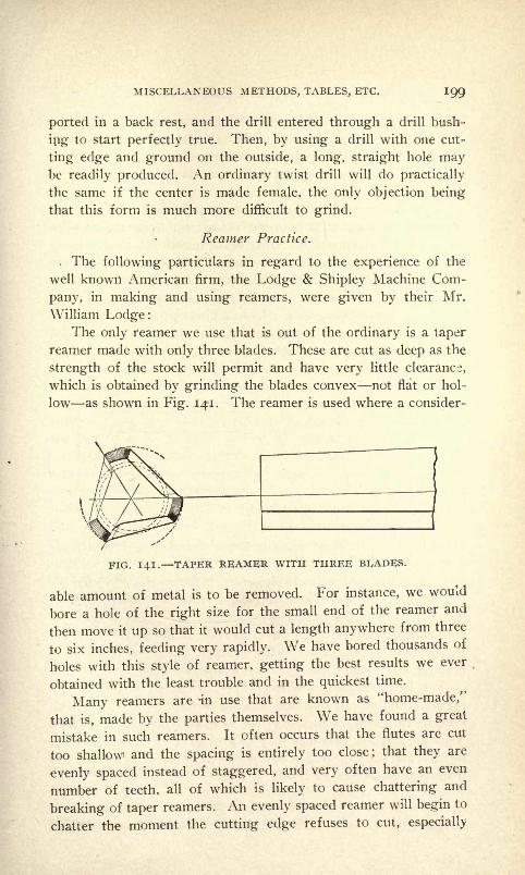
MISCELLANEOUS METHODS, TABLES, ETC. 199
ported in a back rest, and the drill entered through a drill bush-
ing to start perfectly true. Then, by using a drill with one cut-
ting edge and ground on the outside, a long, straight hole maybe readily produced. An ordinary twist drill will do practically
the same if the center is made female, the only objection being
that this form is much more difficult to grind.
Reamer Practice.
. The following particulars in regard to the experience of the
well known American firm, the Lodge & Shipley Machine Com-
pany, in making and using reamers, were given by their Mr.
William Lodge:The only reamer we use that is out of the ordinary is a taper
reamer made with only three blades. These are cut as deep as the
strength of the stock will permit and have very little clearance,
which is obtained by grinding the blades convex not flat or hol-
low as shown in Fig. 141. The reamer is used where a consider-
FIG. 141. TAPER REAMER WITH THREE BLADES.
able amount of metal is to be removed. For instance, we would
bore a hole of the right size for the small end of the reamer and
then move it up so that it would cut a length anywhere from three
to six inches, feeding very rapidly. We have bored thousands of
holes with this style of reamer, getting the best results we ever
obtained with the least trouble and in the quickest time.
Many reamers are -in use that are known as "home-made/'
that is, made by the parties themselves. We have found a great
mistake in such reamers. It often occurs that the flutes are cut
too shallow and the spacing is entirely too close; that they are
evenly spaced instead of staggered, and very often have an even
number of teeth, all of which is likely to cause chattering and
breaking of taper reamers. An evenly spaced reamer will begin to
chatter the moment the cutting edge refuses to cut, especially
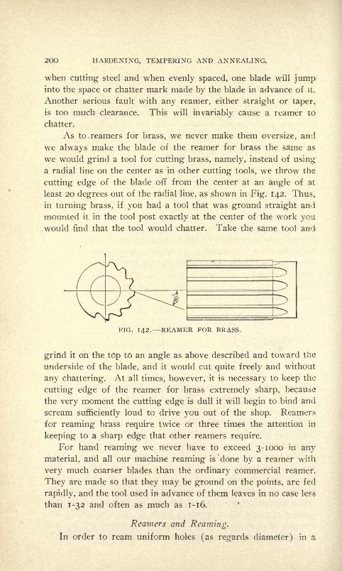
200 HARDENING, TEMPERING AND ANNEALING.
when cutting steel and when evenly spaced, one blade will jumpinto the space or chatter mark made by the blade in advance of it.
Another serious fault with any reamer, either straight or taper,
is too much clearance. This will invariably cause a reamer to
chatter.
As to. reamers for brass, we never make them oversize, and
we always make the blade of the reamer for brass the sa'me as
we would grind a tool for cutting brass, namely, instead of using
a radial line on the center as in other cutting tools, we throw the
cutting edge of the blade off from the center at an angle of at
least 20 degrees out of the radial line, as shown in Fig. 142. Thus,
in turning brass, if you had a tool that was ground straight and
mounted it in the tool post exactly at the center of the work youwould find that the tool would chatter. Take the same tool and
FIG. 142. REAMER FOR BRASS.
grind it on the top to an angle as above described and toward tiie
underside of the blade, and it would cut quite freely and without
any chattering. At all times, however, it is necessary to keep the
cutting edge of the reamer for brass extremely sharp, because
the very moment the cutting edge is dull it will begin to bind and
scream sufficiently loud to drive you out of the shop. Reamers
for reaming brass require twice or three times the attention in
keeping to a sharp edge that other reamers require.
For hand reaming we never have to exceed 3-1000 in any
material, and all our machine reaming is 'done by a reamer with
very much coarser blades than the ordinary commercial reamer.
They are made so that they may be ground on the points, are fed
rapidly, and the tool used in advance of them leaves in no case less
than 1-32 and often as much as 1-16.
Reamers and Reaming.
In order to ream uniform holes (as regards diameter) in a
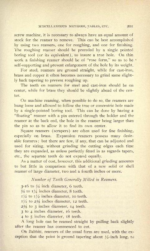
MISCELLANEOUS METHODS, TABLES, ETC. 2OI
screw machine, it is necessary to always have an equal amount of
stock for the reamer to remove. This can be best accomplished
by using two reamers, one for roughing, and one for finishing.
The roughing reamer should be preceded by a single pointed
boring tool (or its equivalent), to insure a true hole. On thin
work a finishing reamer should be of "rose form," so as to be
self-supporting and prevent enlargement of the hole by its weight.
For steel, reamers are ground straight, while for cast-iron,
brass and copper it often becomes necessary to grind same slight-
ly back tapering to prevent roughing up.
The teeth on reamers for steel and cast-iron should be on
center, while for brass they should be slightly ahead of the cen-
ter.
On machine reaming, when possible to do so, the reamers are
hung loose and allowed to follow the true or concentric hole made
by a single-pointed boring tool. This can be done by having a
"floating" reamer with a pin entered through the holder and the
reamer at the back end, the hole in the reamer being larger than
the pin so as to allow it to find its own center.
Square reamers (scrapers) are often used for fine finishing,
especially on brass. Expansion reamers possess many desir-
able features;but there are few, if any, that can be adjusted and
used for sizing, without grinding the cutting edges each time
they are expanded, as unless perfectly fitted in as regards tapers,
etc., the separate teeth do not expand equally.
As a matter of cost, however, this additional grinding amounts
to but little in comparison with that of a new solid or shell
reamer of large diameter, two and a fourth inches or more.
Number of Teeth Generally Milled in Reamers.
3-16 to ^s inch diameter, 6 teeth.
y% to il/4 inches diameter, 8 teeth.
i l/4 to \y2 inches diameter, 10 teeth.
i l/2 to 2^ inches diameter, 12 teeth.
2% to 3 inches diameter, 14 teeth.
3 to 4 inches diameter, 16 teeth.
4 to 5 inches diameter, 18 teeth.
A long hole can be reamed straight by pulling back slightly
after the reamer has commenced to cut.
Oh Babbitt, reamers of the usual form are used, with the ex-
ception that the point is ground tapering about 1/2 -inch long, to
2O2 HARDENING, TEMPERING AND ANNEALING.
a diameter equal to size generated by boring tool. This gives a
smooth hole, free from lines, also prevents rings. Left-hand
spiral flutes are recommended.
On taper reamers for screw machine, use 2j4 inches per foot
and upward. They will cut much easier if made with left-hand
spiral flutes or angle, but on account of difficulty in grinding this
is not often done.
For forming or curving reamers for projectile work, the above
holds good. Reamers il/2 to 2^ inches taper per foot should
have flute straight for finishers, the roughers either of the deepform or with a left-hand spiral thread nicked around. The ream-
ers to il/2 inches taper per foot are fluted left-hand to prevent
drawing in when cutting.
Roughing, taper and forming reamers are sometimes madefrom steel with an undercut, and also with right-hand spiral, and
they remove the stock very rapidly.
Speeds for reaming should range from 20 to 30 per cent less
than turning and drilling speeds. (See tables, pages 123 and
124.)
On large taper reamers, with slight taper, it has been found
good practice to make each tooth a different left-hand spiral and
also to "stagger" the teeth as regards spacing.
Rose reamers are quite often ground tapering, that is, small
at back, .003 to foot, and then are less liable to rough up the hole
they are reaming, and give a straight hole very nearly correct in
diameter.
Grinding Twist Drills.
Grinding twist drills accurately is generally admitted to be
difficult. To know the number of revolutions a drill should run
is of great importance in order to obtain the most economical re-
sults. The illustration, Fig. 143, shows opposite sides of the
Standard Twist Drill Grinding Gage, made of steel i-i6-inch
thick. The angle of the gage is ground to exactly 59 degrees.
The scale on the gage is graduated so that the cutting edges of
the drill can be measured and ground exactly the same length.
The straight edge of the gage is a 2-inch scale graduated by
eighths of an inch ; opposite each eighth mark is a number, which
is the best speed to run a drill of corresponding size of diameter.
In using the gage, hold it with the left hand and place the
drill in the gage with the cutting edges of the drill facing you.
The rest of the lip of the drill must be lower than the cutting
edge, which will give the drill clearance and allow the edges to
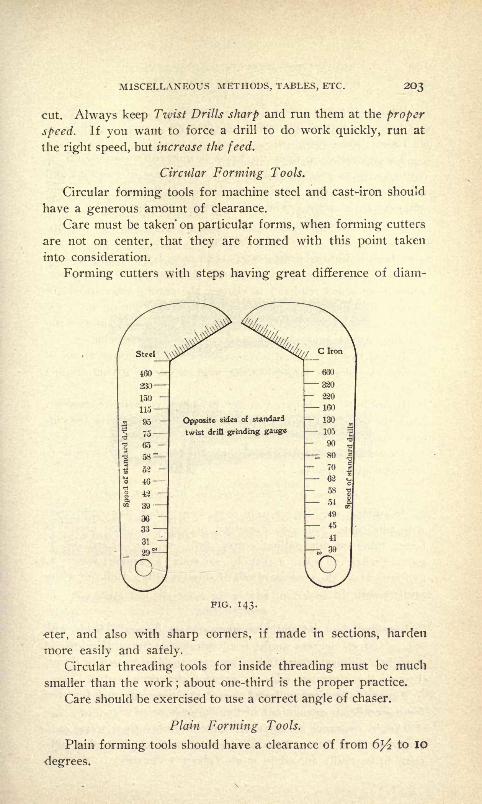
MISCELLANEOUS METHODS, TABLES, ETC. 203
cut. Always keep Twist Drills sliarp and run them at the proper
speed. If you want to force a drill to do work quickly, run at
the right speed, but increase the feed.
Circular Forming Tools.
Circular forming tools for machine steel and cast-iron should
have a generous amount of clearance.
Care must be taken' on particular forms, when forming cutters
are not on center, that they are formed with this point taken
into consideration.
Forming cutters with steps having great difference of diam-
"3 46
Opposite sides of standard
twist drill grinding gauge
PIG. 143.
eter, and also with sharp corners, if made in sections, harden
more easily and safely.
Circular threading tools for inside threading must be much
smaller than the work;about one-third is the proper practice.
Care should be exercised to use a correct angle of chaser.
Plain Forming Tools.
Plain forming tools should have a clearance of from 6 l/2 to IO
degrees.
2O4 HARDENING, TEMPERING AND ANNEALING.
Rake: Machinery steel 8 to 13 degrees.
Rake : Tool steel, medium, 6 to 9 degrees.
Rake : Brass, none.
The clearance on tools for brass is quite often stoned off its
cutting edge to prevent "biting in" (due to ease of cutting) and
then chattering, due to great thickness of chip and consequent
difficulty in severing. The ''stoning off" also tends to act as a
support for the cutter.
Facing.
For steel and cast-iron, cutters with from 6 to 12 degrees rake
cut very freely. *The clearance should be from 3^2 to 10 degrees;
when there is any tendency to chatter, the cutting edge should be
stoned on clearance face sufficiently to prevent "biting in." On
very broad work it often becomes necessary to make cutters with-
out any rake or angle, but allow scraping, to prevent chatter.
In practice it is found advantageous to place cutter ahead of
center, exposing a larger cutting edge to work, giving thinner
chip.
In multiple or inserted cutter heads, it is well to unevenly
space the cutters ; as a precaution against chattering, have the cut-
ters "staggered."
Use machines with large bearings, and with chucks close to
same, for good results.
Lubricant in Milling Steel or Wrought Iron.
In milling steel or wrought iron, keep cutter thoroughly wet
with lubricant. Sal soda dissolved in water is often used. Abetter lubricant for milling cutter, drill, etc., is : Lard oil, ^gallon; whale oil soap, 2 pounds; sal soda, 3 pounds; water, 10
gallons. Have the soap so it will dissolve readily. Boil the whole
until dissolved.
Cou nterb oring.
For cast-iron and steel, counterbores are generally made with
ten to sixteen degrees angle, i. e., spiral ;for brass they are cut
straight. Clearance is from five to ten degrees. On brass,
"stone" the clearance edge to prevent chattering.
Counterbores internally lubricated are recommended for steel
for use to depth of one-half of the diameter or more.
Angle clearance on all tools must be more than spiral gen-erated by feed, at smallest diameter of cutting point plus suffi-
cient to be really forced in work (about 3 degrees ).
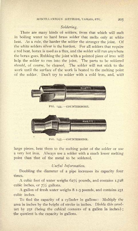
MISCELLANEOUS METHODS, TABLES, ETC. 20 =
Soldering.
There are many kinds of- solders, from that which will melt
in boiling water to hard brass solder that melts only at white
heat. As a rule, the harder the solder the stronger the joint. Ofthe white solders silver is the hardest. For all solders that requirea red heat, borax is used as a flux, and the solder will run anywherethe borax goes. Rubbing the joint with a pointed piece of iron will
help the solder to run into the joint. The parts to be soldered
should, of course, be cleaned. The solder will not stick to the
work until the surface of the work is heated to the melting point
of the solder. Don't try to solder with a cold iron, and, with
FIG. 144. COUNTERBORE.
FIG. 145. COUNTERSINK.
large pieces, heat them to the melting point of the solder or use
a very hot iron. Always use a solder with a much lower melting
point than that of the metal to be soldered.
Useful Information.
Doubling the diameter of a pipe increases its capacity four
times.
A cubic foot of water weighs 62^/2 pounds, and contains 1,728
cubic inches, or jl/2 gallons.
A gallon of fresh water weighs 81-3 pounds, and contains 231
cubic inches.
To find the capacity of a cylinder in gallons : Multiply the
area in inches by the height of stroke in inches. Divide this prod-
uct by 231 (being the cubical contents of a gallon in inches) ;
the quotient is the capacity in gallons.

2O6 HARDENING, TEMPERING AND ANNEALING.
To find the area of a circle or cylinder : Square the diameter
in inches and multiply the product by .7854.
Example : What is the area of a 1 2-inch circle ?
12X12=144+.7854=1 1 3.0976 square inches.
Rust joint cement (quick setting) : i part sal-ammoniac in
powder (by weight), 2 flour of sulphur, 80 iron borings, made to
a paste with water.
Rust joint (slow setting) : 2 parts sal-ammoniac, i flour of
sulphur, 200 iron borings.
The latter is best if joint is not required for immediate use.
Metal to expand in cooling : 9 parts lead, 2 antimony, i bis-
muth.
Glue to resist moisture : i pound of glue in 2 quarts of
skimmed milk.
To color or coat zinc : Dissolve i ounce blue vitriol in 4 ounces
water, add teaspoonful nitric acid. Apply with cloth.
Lacquer for Brass Articles.
A good lacquer for brass articles is made from best orangeshellac dissolved in a good alcohol (i to 2 ounces gum to the
pint) and filtered through filter paper. This is excellent for brass,
and for silver the bleached shellac may be substituted. Some pre-
fer to use the lacquer thin and the work heated to about 115
degrees Fahr., a temperature that will vaporize the alcohol and
leave a firmly adhering coat of gum if the work has been prop-
erly cleansed.
Removing Rust from Polished Steel and Iron.
In the Journal of the United States Artillery directions were
given for caring for ordnance, and the treatment recommended
for rust on polished steel is as follows : Cyanide of potash is
most excellent for removing rust, and should be made much use
of. Instruments of polished steel may be cleaned as follows :
First soak, if possible, in a solution of cyanide of potassium in
the proportion of one ounce of cyanide to four ounces of water.
Allow this to act till all loose rust and scale is removed and then
polish with cyanide soap.
The cyanide soap referred to is made as follows : Potassium
cyanide, precipitated chalk, white Castile soap. Make a saturated
solution of the cyanide and add chalk sufficient to make a creamy
paste. Add the soap cut in fine shavings and thoroughly in-

MISCELLANEOUS METHODS, TABLES, ETC. 2O/
corporate in a mortar. When the mixture is stiff cease to add
soap. It may be well to state that potassium cyanide is a violent
poison.
For removing rust from iron the following is given : Iron maybe quickly and easily cleaned by dipping in or washing with nitric
acid, one part ; muriatic acid, one part ; water, twelve parts.
After using wash with clean water.
Miscellaneous Information.
Area of a circle = diameter X -7854.
Circumference of a circle = diameter X 3- I4 I 6.
Given the area of a circle to find the diameter, divide the area
by .7854 and extract the square root.
Area of a hexagon == length of one side X 2.598.
Cubic contents in inches of a bar of iron = area of one end in
inches by its length, in inches.
Weight of cast iron, per cubic inch, .26 pound ;of wrought
iron, .278 ;of steel, .283 ;
of copper and bronze, .32 ;of brass, .3.
A wrought-iron bar one square inch in section and one yard
long weighs 10 pounds. Steel is about two per cent heavier than
wrought iron. Cast iron is about six per cent lighter than wroughtiron.
To find the surface speed in feet per minute of an emerywheel or milling cutter : Divide the number of revolutions of the
wheel per minute by 12, and multiply the result by 3.1416 times
the diameter of the emery wheel in inches.
To find the number of revolutions a wheel must run for a
given surface speed, multiply the surface speed in feet per min-
ute by 12 and divide the result by 3.1416 times the diameter in
inches.
Given, the diameter of a hexagon nut across the flats, to
find the diameter across corners, multiply the diameter across
flats by 1.156.

208 HARDENING, TEMPERING AM) ANNEALING.
TABLE OF DECIMAL EQUIVALENTS OF MILLIMETERS AND
FRACTIONS OF MILLIMETERS.
ITJ-Q nim. ^ .0003937 inch.
10 mm.
10 cm.
10 dm.
25.4 mm.
: i centimeter= 0.3937 inches.
: i decimeter = 3.937 inches.
= i meter = 39.37 inches.
= i English inch.
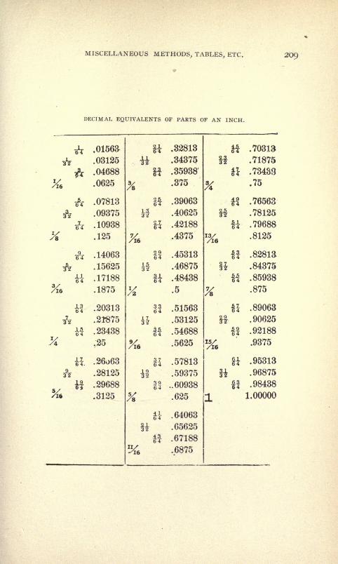
MISCELLANEOUS METHODS, TABLES, ETC. 209
DECIMAL EQUIVALENTS OF PARTS OF AN INCH.
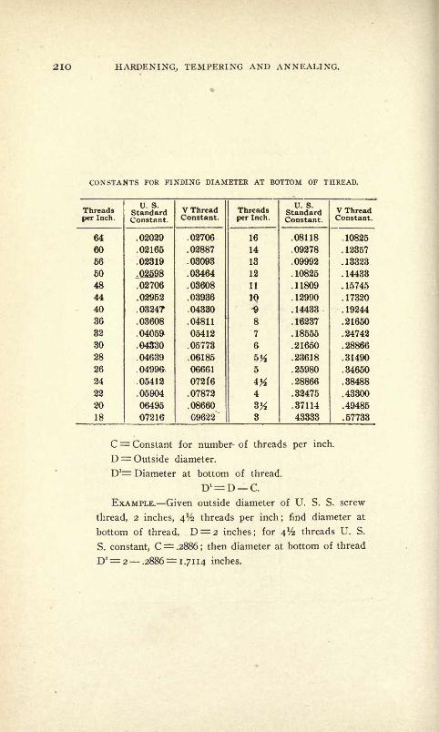
210 HARDENING, TEMPERING AND ANNEALING.
CONSTANTS FOR FINDING DIAMETER AT BOTTOM OF THREAD.
C= Constant for number- of threads per inch.
D= Outside diameter.
D1 Diameter at bottom of thread.
EXAMPLE. Given outside diameter of U. S. S. screw
thread, 2 inches, 4% threads per inch; find diameter at
bottom of thread. D = 2 inches; for 4% threads U. S.
S. constant, C= .2886 ;then diameter at bottom of thread
D*= 2 .2886=1.7114 inches.
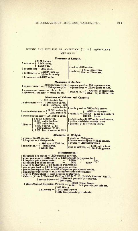
MISCELLANEOUS METHODS, TABLES, ETC. 211
METRIC AND ENGLISH OR AMERICAN (U. S.) EQUIVALENTMEASURES.
( $.37 inches.I meter =
] 3.28083 feet.
( 1.0936yds.1 centimeter = .3937 inch.
Measures of Length.
foot .3048 meter.
( 2.54 centimeters*:
{25.4 millimeters.
1 kilometer = 0.62137 mile.
Measures of Surface.
1 square meter = J10 764 square feet. Jl square yard = .836 square meter.
I 1.196 square yds. il square foot = .0929 square meter.1 square centimeter = 155 s:j. in.1 square millimeter .00155 sq. in
Measures of Volume and Capacityf 35 314 cubic feet.
1 cubic meter = < 1 .308 cubic yards.(264.2 gallons (231
cubic inch).
1 cubic centimeter = .061 cubic inch.
1 cubic decimeter.61.023 cubic inches.
0353 cubic foot.1.0567 quarts (U. S.)2642 gallons (U. S.) .
2.202 lbs.ofwaterat62F.
1 liter
1 cubic yard = .7643 cubic meter.
1 cubic ft. .
f .02832 cubic meter.^28.317 cubic decimeters1 28.317 liters.
1 cubic inch =* 16 387 cubic centimeters.1 gallon (British) = 4 543 liters.1 gallon (U. S.) * 3.785 liters.
1 gram = 15.432 grains.1 kilogram = 2.2046 pounds.
( .9842 ton of 2240 Ibs.
1 metric ton = < 19.68 cwts.1 2204.6 Ibs.
Measures of Weight.1 grain = .0648 gram.1 ounce avoirdupois = 28.35 grams1 pound = .4536 kilograms.
1 ton of 2240 Ibs. = jl
iS,l
?,trlctolia '
/ 1016 kilograms.
MlsceUaneous.1 kilogram per meter = .6720 poundsper foot.
1 gram per square millimeter = 1.422 pounds per square inch.1 kilogram per square meter = 0.2084 foot1 kilogram per cubic meter = .0624 " cubic "
1 degree centigrade = 1.8 degrees Fahrenheit.1 pound per foot = 1.488 kilograms per meter.1 pound per square foot = 4.882 kilograms per square meter.
' '
"act = ltt.02 kilograms per cubiI pound per cubic foot = 16.02 kilograms pe1 degree Fahrenheit = .5556 degrees centigrade.
ic meter.
1 Calorie (French Thermal Unit) = 3.968 B. T. U. (British Thermal Unit)1 Horse Power =
j ijg^gj**un** pcr minule '
1 Watt (Unit of Electrical Power) ={44 P^
1345
Power'
f 1000 Watts.1 Kilowatt =< 1.34 Horse Power
(44240 foot pounds per minute.
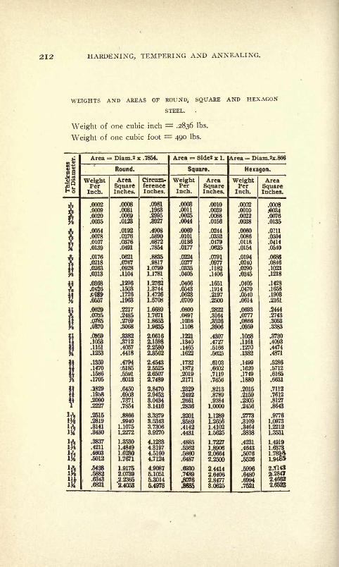
212 HARDENING, TEMPERING AND ANNEALING.
WEIGHTS AND AREAS OF ROUND, SQUARE AND HEXAGON
STEEL.
Weight of one cubic inch = .2836 Ibs.
Weight of one cubic foot = 490 Ibs.
Area = Diam.2 x .7854. Area = Side2 x 1. rea = Diam.2x.866
Round. Square. Hexagon.
WeightPerInch.
AreaSquareInches.
Circum-ferenceInches.
WeightPerInch.
AreaSquareInches.
WeightPerInch.
AreaSquareInches.
.0002
.0009
.0020
.0035
.0054
.0078
.0107
.0139
.0176
.0218
.0263
.0008
.0031
.0123
.0276
.0376
.0491
.0621
.0767
,,.,
.0557
.1104
.1296
.1503
.1726
.0705
.0785
.0370
.1053
.1151
.1253
.1470
.1586
,1705
,1829
.1958
.2090
.2227
.2515
.2819
.3141
.3480
.3837
.4211
.4603
.5012
.5438
.2217
.2485
.2769
.8712
.4057
.4418
.4794
.5185
.5591
.6013
.6450
.6903
.7371
.7854
1.10751.2272
1.35301.4849
1.7671
1.91752.0739
.1963
.4908
.5890
.6872
.7854
.98171.0799
1.1781
1.27621.37441.47261.5708
1.7671
2.4053
1.9635
2.06162.15982.25802.3562
2.45432.55252.6507
2.7489
2.84702.94523.04343.1416
3.33793.53433.73063.9270
4.12334.31974.51604.7124
4.9087
5.10515.3014
5.4978
.0003
.0011
.0025
.0044
.0101
.0136
.0177
.0224
.0277
.0335
.0405
.0466
.0543
.0623
.0709
.0800
.0897
.1036
.1108
1221.1340.1465.1622
.1732
.1872
.2019
J2171
.0010
.0156
.0244
.0352
.0479
.0791
.0977
.1182
.1406
.1651
.1914
.2197
.2500
.2822
.3164
.0002
.0010
.0022
.0038
.0060
.0086
.0118
.0154
.0194
.0240
.0290
.0345
.0405
.0470
.0510
.0614
.0693
.0777
.0008
.034
.0076
.0135
.0211
.0304
.0414
.0510
.0686
.0846
.1023
.1218
.1428
.1658
.1903
.2161
.2444
.2743
.2492
.2661
.4142
.4431
.4307
.4727
.5166
.5625
.6103
.6602
.7119
.7656
.8213
.8789
.93841.0000
L1289.1.26561.41021.5625
1.7227
.5860
.64872.0664
2.2500
2.44142.64062.84773.0625
.1058
.1161
.1270
.1382
.1499
.1620
J749.1880
.2015
.2159
.2305.2456
.2773
.3109
.3464
.4231
.4643
.5076
.6480
.6994
.7521
.3730
.4093
.4474
.4871
.5712
.7112
.7612
.8127
.8643
.9776
1.0973
1.2212
1.3531
2X1432.28472.46622.6532

MISCELLANEOUS METHODS, TABLES, ETC. 213
WEIGHTS AND AREAS OF ROUND, SQUARE AND HEXAGON
STEEL.
Continued.
Multiply above weights by .993 for wrought iron, .918
for cast iron, 1.0331 for cast brass, 1.1209 for copper, and
1.1748 for phos. bronze.

214 HARDENING, TEMPERING AND ANNEALING.
WEIGHT OF IRON AND STEEL SHEETS.
Weights per Square Foot. Kent.
Iron. Steel
Specific gravity 7.7 7.854
Weight per cubic foot 480. 489.6
Weight per cubic inch 2778 .2833
As there are many gauges in use differing from each
other, and even the thicknesses of a certain specified
gauge, as the Birmingham, are not assumed the same by
all manufacturers, orders for sheets and wires should al-
ways state the weights per square foot, or the thickness
in thousandths of an inch.
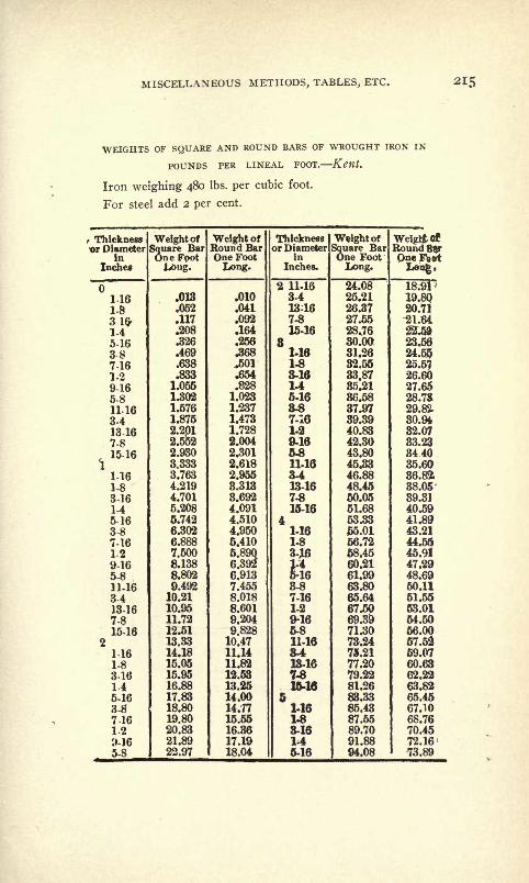
MISCELLANEOUS METHODS, TABLES, ETC. 215
WEIGHTS OF SQUARE AND ROUND BARS OF WROUGHT IRON IN
POUNDS PER LINEAL FOOT. Kent.
Iron weighing 480 Ibs. per cubic foot.
For steel add 2 per cent.

216 HARDENING, TEMPERING AND ANNEALING.
WEIGHTS OF SQUARE AND ROUND BARS OF WROUGHT IRON IN
POUNDS PER LINEAL FOOT. Kent.
Iron weighing 480 Ibs. per cubic foot.
For steel add 2 per cent.
To compute the Weight of Sheet Steel:
Divide the thickness, expressed in thousandths, by 25;
the result is the weight, in pounds, per square foot.
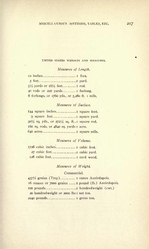
MISCELLANEOUS METHODS, TABLES, ETC. 2I/
UNITED STATES WEIGHTS AND MEASURES.
Measures of Length.
12 inches I foot.
3 feet i yard.
5^ yards or i6l/2 feet I rod.
40 rods or 220 yards I furlong.
8 furlongs, or 1760 yds., or 5,280 ft. i mile.
Measures of Surface.
144 square inches i square foot.
9 square feet i square yard.
30J4 sq. yds., or 27254 sq. ft..i square rod.
160 sq. rods, or 4840 sq. yards i acre.
640 acres i square mile.
Measures of Volume.
1728 cubic inches i cubic foot.
27 cubic feet i cubic yard.
128 cubic feet i cord wood.
Measures of Weight.
Commercial.
437/^2 grains (Troy) i ounce Avoirdupois.
16 ounces or 7000 grains i pound (Ib.) Avoirdupois.
100 pounds i hundredweight (cwt.)
20 hundredweight or 2000 Ibs i net ton.
2240 pounds i gross ton.

218 HARDENING, TEMPERING AND ANNEALING.
TAP DRILLS FOR MACHINE SCREW TAPS.
These drills will give a thread full enough for all prac-
tical purposes, but not a full thread.
SIZE OF DRILLS FOR STANDARD PIPE TAPS.

MISCELLANEOUS METHODS, TABLES, ETC. 219
DIFFERENT STANDARDS FOR WIRE GAGE IN USE IN THE UNITED
STATES.
Dimensions of Sizes in Decimal Parts of an Inch
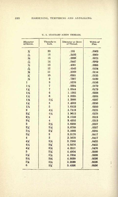
220 HARDENING, TEMPERING AND ANNEALING.
U. S. STANDARD SCREW THREADS.
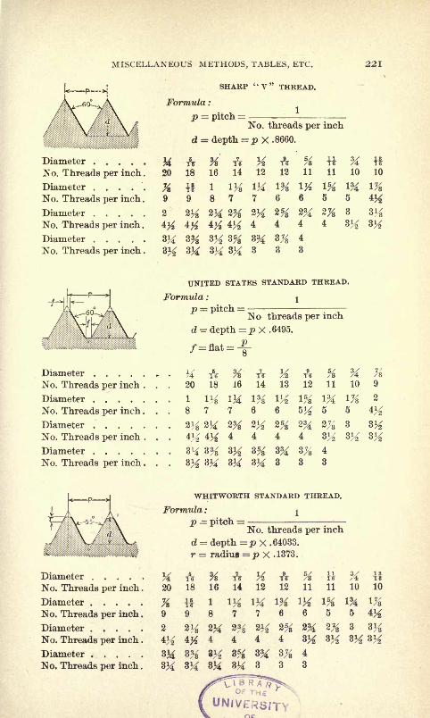
MISCELLANEOUS METHODS, TABLES, ETC. 221

222 HARDENING, TEMPERING AND ANNEALING.
THE ACME STANDARD THREAD.
The Acme Standard Thread is an adaptation of the most
commonly used style of Worm Thread and is intended
to take the place of the square thread.
It is a little shallower than the Worm Thread, but the
same depth as the square thread and much stronger than
the latter.
The various parts of the Acme Standard Thread are
obtained as follows:
Width of Point of tool for Screw or Tap Thread
.3707
.0052
No. of Thds. per in.
Width of Screw or Nut Thread=3707
No. of Thds. per in.
Diameter of Tap Diameter of Screw + .020.
Diameter of Tap or Screw at Root=Ii + .020
No. of Linear Thds. per in.
i
Depth of thread
2 x No. of Thds. per in.
.010
TABLE OF THREAD PARTS.

MISCELLANEOUS METHODS, TABLES, ETC. 223
AVERAGE CUTTING SPEED FOR DRILLS.
The following table represents the most approved prac-
tice in rate of cutting speed for drills ranging from 1-16
inch to 3 inches in diameter.

224 HARDENING, TEMPERING AND ANNEALING.
TABLE OF CUTTING SPEEDS.

MISCELLANEOUS METHODS, TABLES, ETC. 225
The preceding table is a convenient one for rinding the
number of revolutions per minute required to give a peri-
phery speed from 5 to 50 feet per minute of diameters
from y2 inch to 30 inches.
EXAMPLES A mill 2 inches diam. to have a periphery
speed of 35 feet per minute, should make about 67 revo-
lutions, while a i^-inch mill should make 120 revolu-
tions to have the same periphery speed. If a 34-inch
mill makes 250 revolutions per minute, the periphery speed
is about 50 feet.
Horse Power of Belts. A good method of finding the
power of a belt, assuming 800 feet travel per minute of
i inch single belt per horse power.
FORMULA .00033 D. R. B= Horse power.
D = Diameter of pulley in inches.
R= Revolutions of pulley per minute.
B Width of belt in inches.
EXAMPLE i8-inch pulley, 3-inch belt, 150 revolutions
per minute, .00033 x 18 x 150 x 3 2.67 H. P.
If looo feet is assumed instead of 800 feet, use constant
.00026 in place of .00033.
CUTTER LUBRICANT.
A good lubricant for cutters milling steel or wrought
iron, is i Ib. tallow or i Ib. hard or soft soap. Boil and
add water until about the consistency of cream.

CHAPTER XII.
GRINDING THE ACCURATE AND RAPID GRINDING OF TOOLS ANDSMALL MACHINE PARTS EMERY WHEELS.
Cutter and Tool Grinding.
A subject germain to the treatment of steel is that of grinding,as in most lines of steel working it occupies an important posi-
tion. In the following are shown illustrations of approved ma-
chines for the grinding of fine tool work and accurate small ma-
chine parts. Descriptions are also given of the correct methods
of grinding the different tools and parts.
The machine illustrated in Fig. 146 is of a type used ex-
tensively for general toolroom work and is one of a class of uni-
versal cutter and tool grinders which has been greatly improvedand developed during the last few years. It may be used to grind
accurately and rapidly work of the following kinds and sizes :
Milling machine cutters 12 inches in diameter when not more
than i inch wide.
Work 14 inches long held between centers when the diameter
of rotation is not more than 8 inches. These dimensions are givenas the limit for irregular pieces and not for heavy, solid cylin-
ders.
Work 14 inches long can be ground by using an emery wheel
on each side of the head.
Reamers and shell counterbores of large or small sizes.
Gear cutters and formed cutters of every description.
Flat surfaces, such as shear plates, dies and gages.Hardened bushing and other pieces to be ground internally.
Conical surfaces, such as taper bearings and mandrels, andsmall cylindrical machine parts which are to be finished with ex-
treme accuracy.
The foregoing list does not give the limit of the capacity of
machine, but rather indicates in a general way what is possible in
its use.
For a more particular presentation of the kinds of work which
can be and are actually ground on such machines, reference is
made to the following pages.
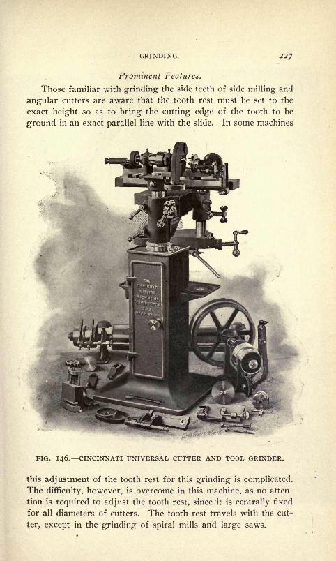
GRINDING. 227
Prominent Features.
Those familiar with grinding the side teeth of side milling and
angular cutters are aware that the tooth rest must be set to the
exact height so as to bring the cutting edge of the tooth to be
ground in an exact parallel line with the slide. In some machines
FIG. 146. CINCINNATI UNIVERSAL CUTTER AND TOOL GRINDER.
this adjustment of the tooth rest for this grinding is complicated.
The difficulty, however, is overcome in this machine, as no atten-
tion is required to adjust the tooth rest, since it is centrally fixed
for all diameters of cutters. The tooth rest travels with the cut-
ter, except in the grinding of spiral mills and large saws.

228 HARDENING, TEMPERING AND ANNEALING.
4------ 3' ---
N
Sr
jL-im
_ -
^
a
i
FIG. 147. SHAPES AND SIZES OF EMERY WHEELS TO USE FOR TOOL
GRINDING.

GRINDING. 229
FIG. 148. SAMPLES OF GROUND WORK DONE) IN UNIVERSAL CUTTER.
AND TOOL GRINDER, FIG. 146.
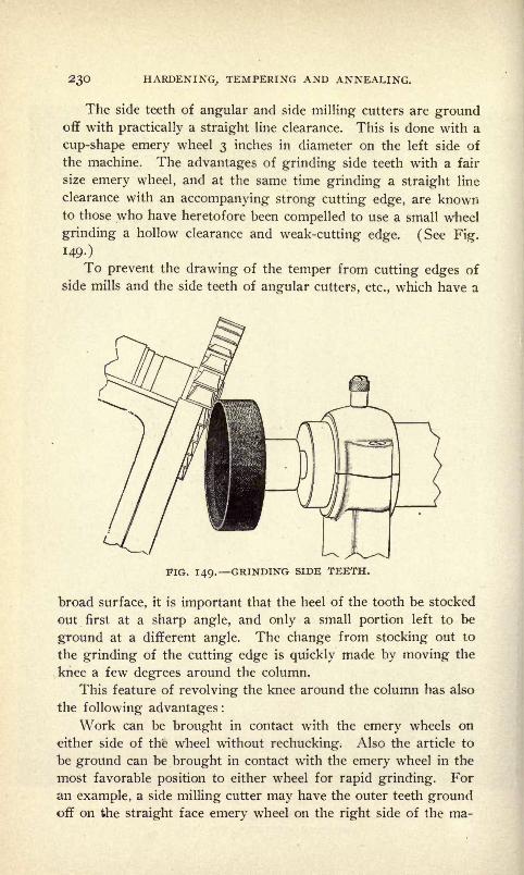
230 HARDENING., TEMPERING AND ANNEALING.
The side teeth of angular and side milling cutters are groundoff with practically a straight line clearance. This is done with a
cup-shape emery wheel 3 inches in diameter on the left side of
the machine. The advantages of grinding side teeth with a fair
size emery wheel, and at the same time grinding a straight line
clearance with an accompanying strong cutting edge, are knownto those who have heretofore been compelled to use a small wheel
grinding a hollow clearance and weak-cutting edge. (See Fig.
149-)
To prevent the drawing of the temper from cutting edges of
side mills and the side teeth of angular cutters, etc., which have a
FIG. 149. GRINDING SIDE TEETH.
broad surface, it is important that the heel of the tooth be stocked
out first at a sharp angle, and only a small portion left to be
ground at a different angle. The change from stocking out to
the grinding of the cutting edge is quickly made by moving the
knee a few degrees around the column.
This feature of revolving the knee around the column has also
the following advantages:
Work can be brought in contact with the emery wheels on
either side of the wheel without rechucking. Also the article to
be ground can be brought in contact with the emery wheel in the
most favorable position to either wheel for rapid grinding. For
an example, a side milling cutter may have the outer teeth groundoff on the straight face emery wheel on the right side of the ma-

GRINDING. 231
chine, and the side teeth on the cup-shape wheel at the left side
of the machine, without taking the cutter off the arbor or disturb-
ing the tooth guide.
Cutters of small diameters and sharp angles can be groundwithout the cutter, mandrel or centers striking the belt or emerywheel head. Also in grinding the shoulders, on work revolved
between centers, the periphery instead of the side of a flat wheel
can be used.
Grinding a Spiral Mill.
Fig. 150 shows the long slide at the rear of the column and
nearly parallel to the emery wheel spindle, the two swivels set at
FIG. 150. GRINDING A SPIRAL MILL.
zero, a flat wheel on the right of the emery wheel head and the
mill on the mandrel held between centers.
Fig. 151 shows a side elevation of the wheel, the centering
gage, the tooth rest No. 2 and the end of the mill.
Fig. 152 is an elevation showing the rim of the wheel, the
face of the mill and the tooth rest in the position required when
the mill is turned for grinding the next tooth.
Directions : Adjust the plane of centers below the plane of
the spindle the distance required for clearance. If the mill is
cylindrical, set the table at zero;and if not, set it for the required
taper. Set the stops on the long slide so that, the mill having
passed, the cutter will still be held by the flexible part of the
tooth rest, which will then act as a spring pawl when turning the
mill to bring the next tooth into position for grinding. In setting

232 HARDENING, TEMPERING AND ANNEALING.
the tooth rest the centering gage must come directly opposite to
part of the wheel which strikes the cutter.
Grinding Angular Cutters.
Fig. 153 illustrates the grinding when the cutter is left-hand.
The flat wheel is on the right-hand end of spindle, the long
slide is at the rear and right-hand, the cutter is held on work
spindle and the tooth rest No. 4 is on the horizontal swivel.
Directions : Set the plane of centers below plane of spindle.
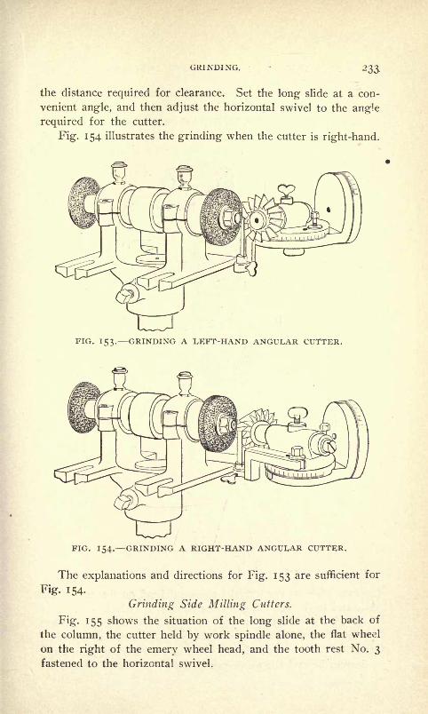
GRINDING. 233.
the distance required for clearance. Set the long slide at a con-
venient angle, and then adjust the horizontal swivel to the angle
required for the cutter.
Fig. 154 illustrates the grinding when the cutter is right-hand.
FIG. 153. GRINDING A LEFT-HAND ANGULAR CUTTER.
FIG. 154. GRINDING A RIGHT-HAND ANGULAR CUTTER.
The explanations and directions for Fig. 153 are sufficient for
Fig- 154.
Grinding Side Milling Cutters.
Fig- 155 shows the situation of the long slide at the back of
the column, the cutter held by work spindle alone, the flat wheel
on the right of the emery wheel head, and the tooth rest No. 3
fastened to the horizontal swivel.
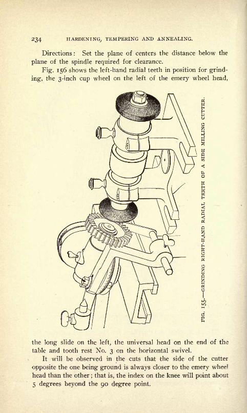
234 HARDENING, TEMPERING AND ANNEALING.
Directions: Set the plane of centers the distance below the
plane of the spindle required for clearance.
Fig. 156 shows the left-hand radial teeth in position for grind-
ing, the 3-inch cup wheel on the left of the emery wheel head,
the long slide on the left, the universal head on the end of the
table and tooth rest No. 3 on the horizontal swivel.
It will be observed in the cuts that the side of the cutter
opposite the one being ground is always closer to the emery whee]
head than the other;that is, the index on the knee will point about
5 degrees beyond the 90 degree point.

GRINDING. 235
Directions : Set the vertical swivel so as to depress the outer
end of the work spindle the number of degrees required for clear-
ance. This ranges from 5 degrees to 20 degrees, depending uponthe clearance required.
The manner in which shell counterbores may be ground is
shown clearly in Fig. 157, and but little description is necessary.
In grinding such tools, a stud, which fits the taper hole in the
work spindle and the hole in the counterbore, is required.
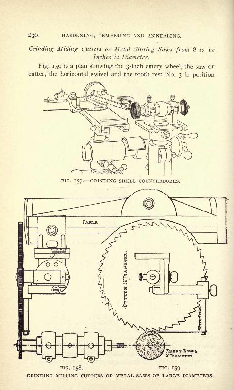
236 HARDENING, TEMPERING AND ANNEALING.
Grinding Milling Cutters or Metal Slitting Saws from 8 to 12
Inches in Diameter.
Fig. 159 is a plan showing the 3-inch emery wheel, the saw or
cutter, the horizontal swivel and the tooth rest No. 3 in position
FIG. 157. GRINDING SHELL COUNTERBORES.
3'DlAMETER
PIG. 158. FIG. 159.
GRINDING MILLING CUTTERS OR METAL SAWS OF LARGE DIAMETERS.
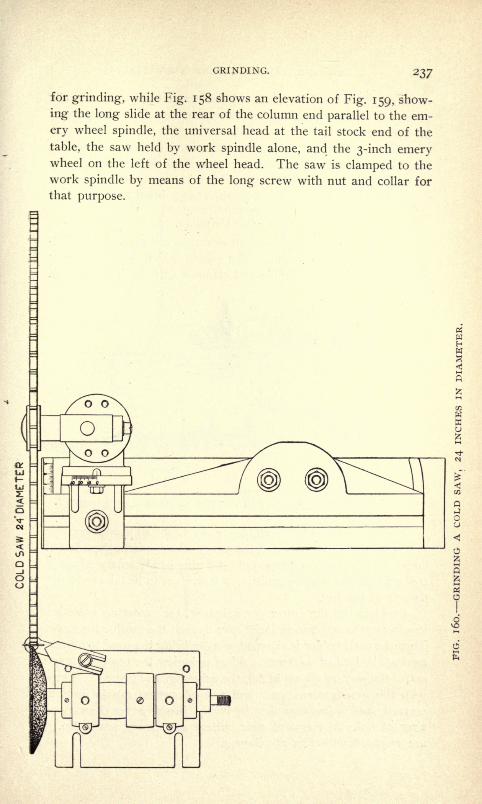
GRINDING. 237
for grinding, while Fig. 158 shows an elevation of Fig. 159, show-
ing the long slide at the rear of the column end parallel to the em-
ery wheel spindle, the universal head at the tail stock end of the
table, the saw held by work spindle alone, and the 3-inch emerywheel on the left of the wheel head. The saw is clamped to the
work spindle by means of the long screw with nut and collar for
that purpose.
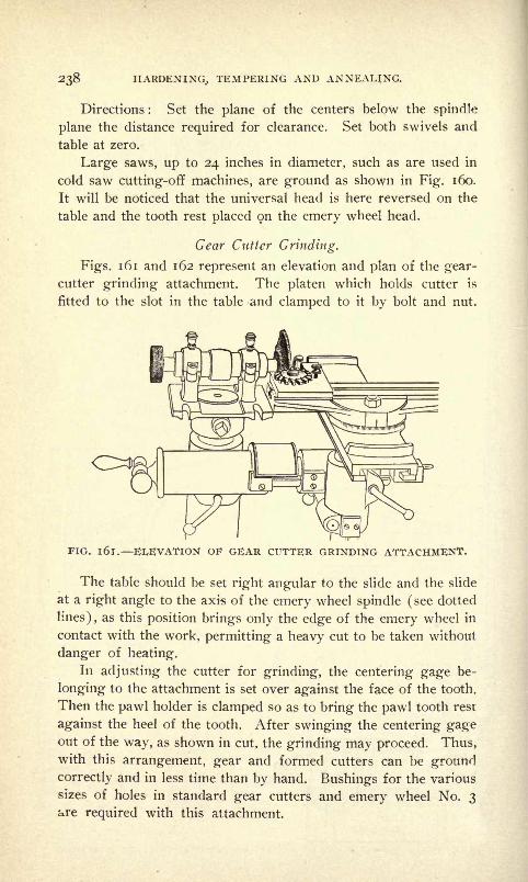
238 HARDENING, TEMPERING AND ANNEALING.
Directions : Set the plane of the centers below the spindle
plane the distance required for clearance. Set both swivels and
table at zero.
Large saws, up to 24 inches in diameter, such as are used in
cold saw cutting-off machines, are ground as shown in Fig. 160.
It will be noticed that the universal head is here reversed on the
table and the tooth rest placed on the emery wheel head.
Gear Cutter Grinding.
Figs. 161 and 162 represent an elevation and plan of the gear-
cutter grinding attachment. The platen which holds cutter is
fitted to the slot in the table and clamped to it by bolt and nut.
FIG. l6l. ELEVATION OF GEAR CUTTER GRINDING ATTACHMENT.
The table should be set right angular to the slide and the slide
at a right angle to the axis of the emery wheel spindle (see dotted
lines), as this position brings only the edge of the emery wheel in
contact with the work, permitting a heavy cut to be taken without
danger of heating.
In adjusting the cutter for grinding, the centering gage be-
longing to the attachment is set over against the face of the tooth.
Then the pawl holder is clamped so as to bring the pawl tooth rest
against the heel of the tooth. After swinging the centering gageout of the way, as shown in cut, the grinding may proceed. Thus,with this arrangement, gear and formed cutters can be groundcorrectly and in less time than by hand. Bushings for the various
sizes of holes in standard gear cutters and emery wheel No. 3^re required with this attachment.

GRINDING. 239

240 HARDENING, TEMPERING AND ANNEALING.
Grinding Formed Cutters.
Fig. 163 shows the table and long slide on the right of the col-
umn, the dish-shaped wheel on the right-hand end of the spindle,
the two arms by means of which the center of the cutter maybe held below the top of the table and the tooth rest No. 5 which
engages with the heel of the tooth to be ground.
Directions : Set the axis of the long slide at right angle to
that of the spindle by means of dial on column. Set the lower line
FIG. 163. GRINDING A FORMED CUTTER.
of centers so that it will intersect the vertical diameter at the
side of the wheel. This adjustment can be readily made by bring-
ing the point of the tail stock center nearly in line with the side of
a straight edge held vertically against the flat side of the wheel.
Put the cutter on a mandrel between centers and set the face of a
tooth against the side of the wheel, making an allowance for
amount to be ground off. To hold the face in this position, ad-
just tooth rest No. 5 to the heel of the tooth. Determine the
depth of cut by short slide.

GRINDING. 24 I
How to Grind a Worm Wheel Hob.
Fig. 164 shows the long slide on the left of the column, the
special attachment on the table for holding the mandrel, the disk-
shape wheel No. 3 on the left-hand end of the spindle and the
table in line with the long slide.
Directions: See those given for grinding formed cutters.
Grinding a Hand Reamer.
Fig. 165 shows the long slide on the left, the cup-shape wheel
FIG. 164. GRINDING A WORM WHEEL HOB.
on the left-hand end of spindle and the tooth rest No. I fastened
to the top of the table.
Directions : Set the tooth rest below plane of centers a suffi-
cient distance for clearance when grinding straight reamers. Set
the table to grind straight. To grind bevel on end of reamer set
table to angle required, or as shown in Fig. 166.
Grinding a Taper Reamer.
Fig. 167 shows the long slide at the rear right of emery wheel
head, the table set obliquely to the side, the swivels at zero, the
reamer between dead centers, a flat wheel at the right-hand end>of the spindle and the tooth rest No. 3 fastened to the swivel.
Directions: Set the tooth rest in the plane of centers. Set

242 HARDENING, TEMPERING AND ANNEALING.
. 165. GRINDING A HAND REAMER.
FIG. l66. GRINDING BEVEL ON END OF REAMER.
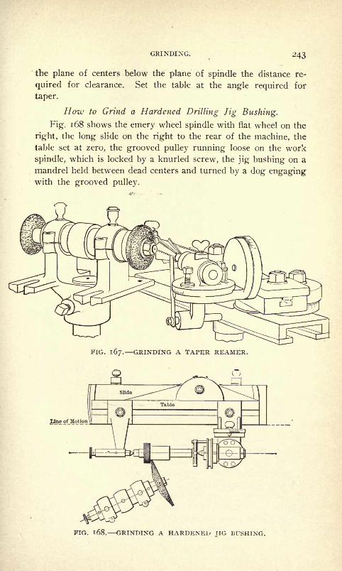
GRINDING. -'43
the plane of centers below the plane of spindle the distance re-
quired for clearance. Set the table at the angle required for
taper.
How to Grind a Hardened Drilling Jig Bushing.
Fig. 168 shows the emery wheel spindle with flat wheel on the
right, the long slide on the right to the rear of the machine, the
table set at zero, the grooved pulley running loose on the work
spindle, which is locked by a knurled screw, the jig bushing on a
mandrel held between dead centers and turned by a dog engagingwith the grooved pulley.
FIG. 167. GRINDING A TAPER REAMER.
Jdne on*otio
. 168. GRINDING A HARDENED JIG BUSHING.

244 HARDENING, TEMPERING AND ANNEALING.
How to Grind a Taper Spindle.
Fig. 169 shows the long slide at the back of the column, the
wheel on the right of the spindle, the table set for the required
taper, and the grooved pulley running loose on the work spindle.
In circular grinding when the piece is held by the work spindle
alone the grooved pulley is locked to the spindle.
Emery wheel shape No. 3 is used for taking deep cuts; shape
No. 5 for finishing the surface.
The centers in work that has to be ground must be very care-
fully made and held to proper shape. Hardened pieces must have
centers lapped as nearly round as possible in order to obtain goodresults.-
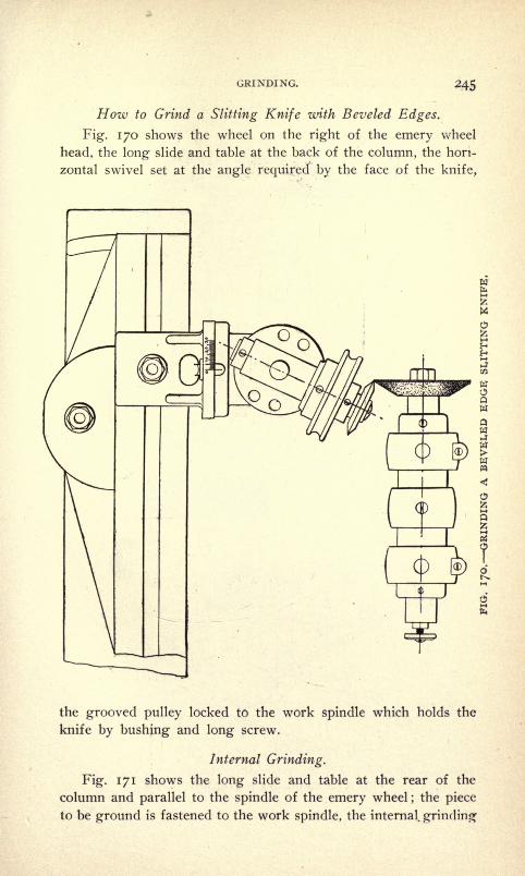
GRINDING. 245
How to Grind a Slitting Knife with Beveled Edges.
Fig. 170 shows the wheel on the right of the emery wheel
head, the long slide and table at the back of the column, the hori-
zontal swivel set at the angle required by the face of the knife,
the grooved pulley locked to the work spindle which holds the
knife by bushing and long screw.
Internal Grinding.
Fig. 171 shows the long slide and table at the rear of the
column and parallel to the spindle of the emery wheel;the piece
to be ground is fastened to the work spindle, the internal, grinding
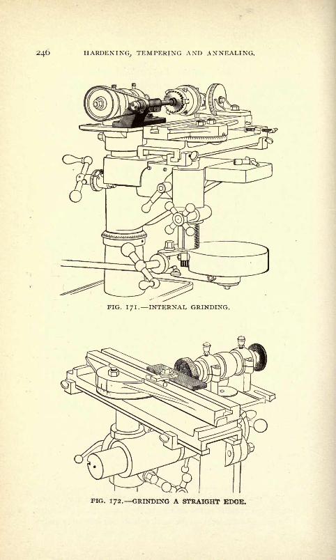
246 HARDENING, TEMPERING AND ANNEALING.
FIG. IJI. INTERNAL GRINDING.
FIG. 172. GRINDING A STRAIGHT EDGE.
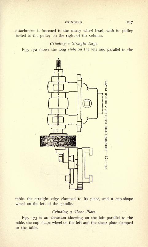
GRINDING. 247
attachment is fastened to the emery wheel head, with its pulley
belted to the pulley on the right of the column.
Grinding a Straight Edge.
Fig. 172 shows the long slide on the left and parallel to the
table, the straight edge clamped to its place, and a cup-shapewheel on the left of the spindle.
Grinding a Shear Plate.
Fig. 173 is an elevation showing on the left parallel to the
table, the cup-shape wheel on the left and the shear plate clampedto the table.
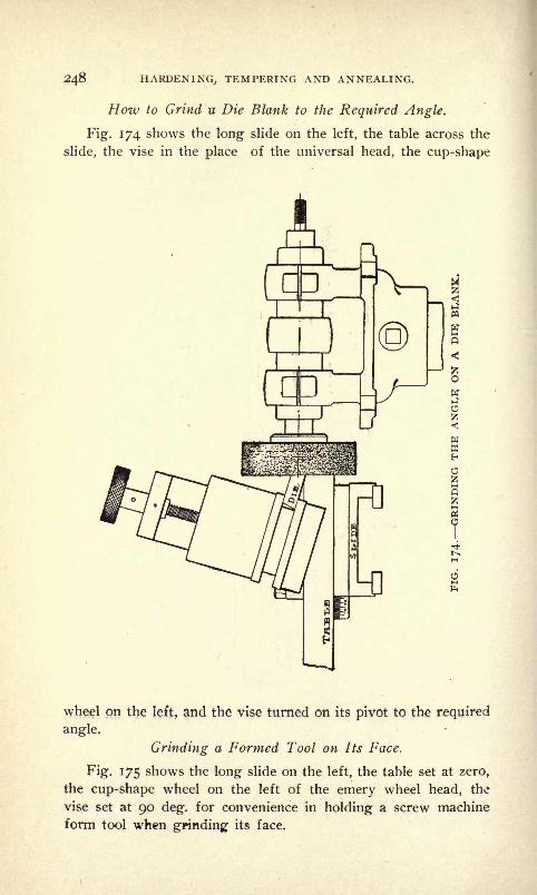
248 HARDENING,, TEMPERING AND ANNEALING.
How to Grind u Die Blank to the Required Angle.
Fig. 174 shows the long slide on the left, the table across the
slide, the vise in the place of the universal head, the cup-shape
wheel on the left, and the vise turned on its pivot to the required
angle.
Grinding a Formed Tool on Its Face.
Fig. 175 shows the long slide on the left, the table set at zero,
the cup-shape wheel on the left of the emery wheel head, the
vise set at 90 deg. for convenience in holding a screw machine
form tool when grinding its face.

GRINDING. 249
FIG. 175. GRINDING THE FACE OF A FORMED TOOI,.
PIG. 176. CUTTING OFF WITH THE EMERY WHEEL.
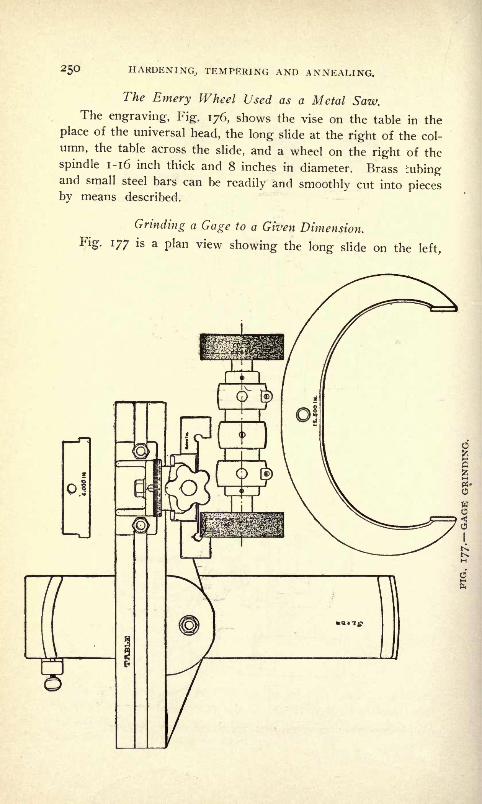
250 HARDENING, TEMPERING AND ANNEALING.
The Emery Wheel Used as a Metal Saw.The engraving, Fig. 176, shows the vise on the table in the
place of the universal head, the long slide at the right of the col-
umn, the table across the slide, and a wheel on the right of the
spindle 1-16 inch thick and 8 inches in diameter. Brass iubingand small steel bars can be readily and smoothly cut into piecesby means described.
Grinding a Gage to a Given Dimension,
Fig. 177 is a plan view showing the long slide on the left,
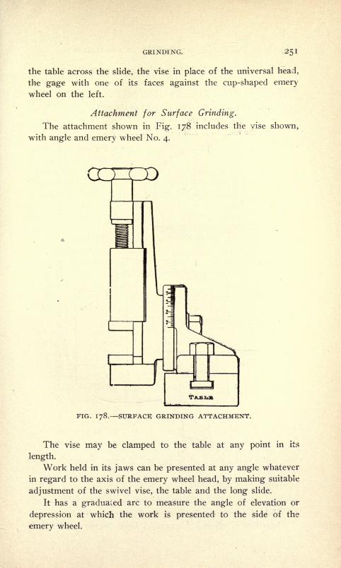
GRINDING. 251
the table across the slide, the vise in place of the universal head,
the gage with one of its faces against the cup-shaped emerywheel on the left.
Attachment for Surface Grinding.
The attachment shown in Fig. 178 includes the vise shown,
with angle and emery wheel No. 4.
FIG. 178. SURFACE GRINDING ATTACHMENT.
The vise may be clamped to the table at any point in its
length.
Work held in its jaws can be presented at any angle whatever
in regard to the axis of the emery wheel head, by making suitable
adjustment of the swivel vise, the table and the long slide.
It has a graduated arc to measure the angle of elevation or
depression at which the work is presented to the side of the
emery wheel.

252 HARDENING, TEMPERING AND ANNEALING.
Hoiv to Grind Milling Cutters and Metal-Slitting Saute Straight
or Concave.
Fig". 179 shows the emery wheel head with a wheel on the
right, the long slide and table parallel to the emery wheel spindle,
the horizontal swivel set at 90, and the saw fastened to work-
spindle.
The round belt should be as loose as possible.
General Directions.
Hold the cutter to the tooth rest by hand.
In all cases when it is possible, limit the movement of the

GRINDING. 253
long slide by the stops furnished for the purpose, for the follow-
ing reasons :
It prevents the wheel from striking the head stock or cutter
in concave grinding.
It prevents the wheel from running too deep into formed
cutters and side milling cutters when grinding radial teeth.
It prevents the cutter from passing off the tooth rest, besides
being convenient in quite a number of other instances occurringin the use of the grinder.
It is convenient and sometimes necessary in grinding cutters
for clearance on the right-hand end of the emery wheel spindle,
to swing the knee on the column to the right at an angle of from
5 to 15. This applies especially in angle cutters and small
cylindrical cutters, when the belt is liable to strike the cutter or
center.
After cutters have been reground once or twice the land be-
comes thick;
it is very convenient under these conditions to
swing the knee slightly around the column 2 or 3 degrees, and
grind with a heavy broad cut between the teeth so as to reduce
the amount of the land.
After the land is reduced to the proper width a slight move-
ment of the knee back about i degree will alter the angle of the
cut in such a way as to produce a narrow land with a keen cutting
edge without danger of drawing temper.
The life of a cutter by this means is very much prolonged.In using the lever or screw feed handles, adjust them by
means of the clamp screws at bottom of long slide holder to the
most convenient position.
Use the centering gage for determining the relative heightof center of emery wheel spindle and tail stock center.
Diamond Tool Holder.
In order to obtain a good cutting edge and make a smooth
finish on work, the emery wheel on a universal cutter and tool
grinder must run true and have its cutting surface parallel with
the movement on the slide of the machine. The cut, Fig. 180,
shows a diamond tool and holder for truing emery wheels. This
tool is made to be used either by hand or clamped to the table
of fhe machine so that the diamond can be passed across the wheel
in line with the slide in any position. It is absolutely necessary
to have the wheel perfectly true on work ground between centers.
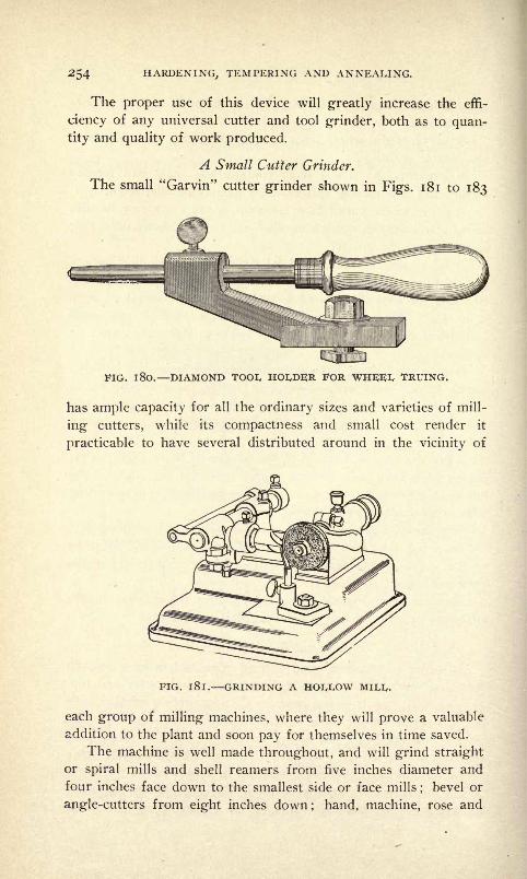
254 HARDENING., TEMPERING AND ANNEALING.
The proper use of this device will greatly increase the effi-
ciency of any universal cutter and tool grinder, both as to quan-
tity and quality of work produced.
A Small Cutter Grinder.
The small "Garvin" cutter grinder shown in Figs. 181 to 183
FIG. 1 80. DIAMOND TOOL HOLDER FOR WHEEL TRUING.
has ample capacity for all the ordinary sizes and varieties of mill-
ing cutters, while its compactness and small cost render it
practicable to have several distributed around in the vicinity of
FIG. l8l. GRINDING A HOLLOW MILL.
each group of milling machines, where they will prove a valuable
addition to the plant and soon pay for themselves in time saved.
The machine is well made throughout, and will grind straight
or spiral mills and shell reamers from five inches diameter and
four inches face down to the smallest side or face mills;
bevel or
angle-cutters from eight inches down; hand, machine, rose and
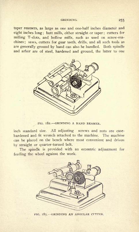
GRINDING. 255
taper reamers, as large as one and one-half inches diameter and
eight inches long ; butt mills, either straight or taper ; cutters for
milling T-slots, and hollow mills, such as used on screw-ma-
chines; saws, cutters for gear teeth, drills, and all such tools as
are generally ground by hand can also be handled. Both spindle
and arbor are of steel, hardened and ground, the latter to one
FIG. l82. GRINDING A HAND REAMER.
inch standard size. All adjusting screws and nuts are case-
hardened and fit wrench attached to the machine. The machine
can be placed on the bench where most convenient and driven
by straight or quarter-turned belt.
The spindle is provided with an eccentric adjustment for
feeding the wheel against the work.
PIG. 1 83.--GRINDING AN ANGULAR CUTTER.
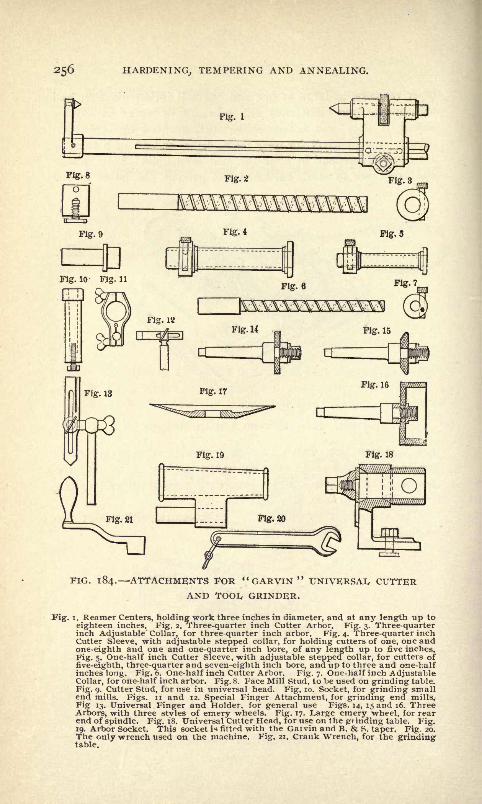
HARDENING, TEMPERING AND ANNEALING.
FIG. 184. ATTACHMENTS FOR " GARVIN " UNIVERSAL, CUTTERAND TOOI, GRINDER.
i. Reamer Centers, holding work three inches in diameter, and at any length up to
eighteen inches. Fig. 2. Three-quarter inch Cutter Arbor. Fig. 3. Three-quarterinch Adjustable Collar, for three-quarter inch arbor. Fig. 4. Three-quarter inchCutter Sleeve, with adjustable stepped collar, for holding cutters of one, one andone-eighth and one and one-quarter inch bore, of any length up to five inches.Fig. 5. One-half inch Cutter Sleeve, with adjustable stepped collar, for cutters offive-eighth, three-quarter and seven-eighth inch bore, and up to three and one-halfinches long. Fig. 6. One-half inch Cutter Arbor. Fig. 7. One-half inch AdjustableCollar, for one-half inch arbor. Fig. 8. Face Mill Stud, to be used on grinding table.
Fig. 9. Cutter Stud, for use in universal head. Fig. 10. Socket, for grinding smallend mills. Figs, n and 12. Special Finger Attachment, for grinding end mills.Fig 13. Universal Finger and Holder, for general use Figs. 14, 15 and 16. ThreeArbors, with three styles of emery wheels. Fig. 17. 1+arge emery wheel, for rearend of spindle. Fig. 18. Universal Cutter Head, for use on the grinding table. Fig.19. Arbor Socket. This socket is fitted with the Gai vin and B. & VS. taper. Fig. 20.
The only wrench used on the machine. Fig. 21. Crank Wrench, for the grindingtable.
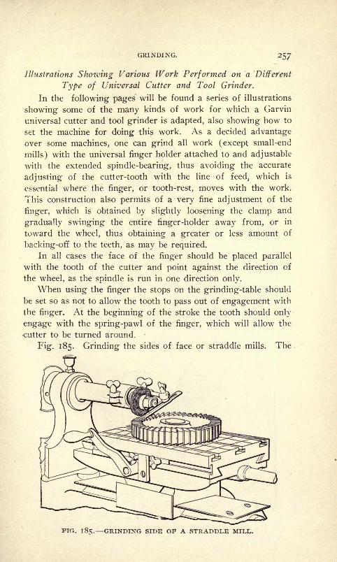
GRINDING. 257
Illustrations Shozving Various Work Performed on a 'Different
Type of Universal Cutter and Tool Grinder.
In the following pages will be found a series of illustrations
showing some of the many kinds of work for which a Garvin
universal cutter and tool grinder is adapted, also showing how to
set the machine for doing this work. As a decided advantage
over some machines, one can grind all work (except small-end
mills) with the universal finger holder attached to and adjustable
with the extended spindle-bearing, thus avoiding the accurate
adjusting of the cutter-tooth with the line of feed, which is
essential where the finger, or tooth-rest, moves with the work.
This construction also permits of a very fine adjustment of the
finger, which is obtained by slightly loosening the clamp and
gradually swinging the entire finger-holder away from, or in
toward the wheel, thus obtaining a greater or less amount of
backing-off to the teeth, as may be required.
In all cases the face of the finger should be placed parallel
with the tooth of the cutter and point against the direction of
the wheel, as the spindle is run in one direction only.
When using the finger the stops on the grinding-table should
be set so as not to allow the tooth to pass out of engagement with
the finger. At the beginning of the stroke the tooth should only
engage with the spring-pawl of the finger, which will allow the
cutter to be turned around.
Fig. 185. Grinding the sides of face or straddle mills. The
FIG. 185. GRINDING SIDE OF A STRADDLE

HARDENING; TEMPERING AND ANNEALING.
cutter is held directly on the table and revolved on the face mill
stud (Fig. 8).
Fig. 186. Grinding the reverse side of the same face mill;
FIG. 1 86. GRINDING THE REVERSE SIDE OF A STRADDLE MILL.
no change in adjustment has been made, only the sliding plat-
form has been moved on the knee.
Fig. 187. Grinding the face of a straddle mill, carried on a
stud in the universal cutter head (Figs. 9 and 18) ;the grinding
table being locked.
FIG. 187. GRINDING THE FACE OF A STRADDLE MILL.
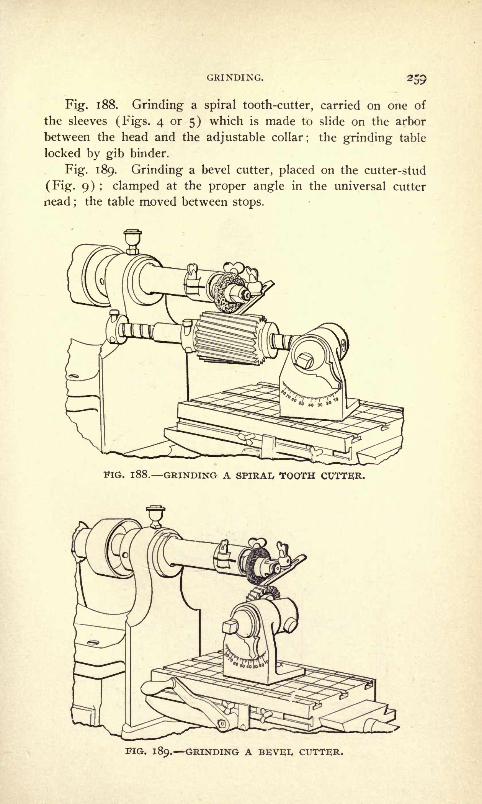
GRINDING. 259
Fig. 1 88. Grinding a spiral tooth-cutter, carried on one of
the sleeves (Figs. 4 or 5) which is made to slide on the arbor
between the head and the adjustable collar; the grinding table
locked by gib binder.
Fig. 189. Grinding a bevel cutter, placed on the cutter-stud
(Fig. 9) ; clamped at the proper angle in the universal cutter
nead;
the table moved between stops.
EIG. 188. GRINDING A SPIRAL TOOTH CUTTER.
FIG. 189. GRINDING A BEVEI, CUTTER.
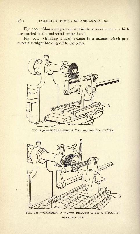
260 HARDENING, TEMPERING AND ANNEALING.
Fig. 190.'
Sharpening a tap held in the reamer centers, which
are carried in the universal cutter head.
Fig. 191. Grinding a taper reamer in a manner which pro-cures a straight backing off to the teeth.
FIG. 190. SHARPENING A TAP ALONG ITS FLUTES.
FIG. 191. GRINDING A TAPER REAMER WITH A STRAIGHT
BACKING OFF.

GRINDING. 26l
Fig. 192. Grinding a taper reamer so as to produce a shear
form of cutting edge.
Fig. 193. Grinding the face of a small end mill, held in the
end mill fixture (Fig. 10) using the special finger-holder (Figs.
ii and 12).
FIG. 192. GRINDING A TAPER REAMER WITH A SHEARBACKING OFF.
FIG. 193. GRINDING THE FACE OF A SMALL END MILL.

262 HARDENING, TEMPERING AND ANNEALING.
Fig. 194. Grinding the sides of an end mill, using the same
fixtures.
Fig. :95- Grinding the face of a double end butt mill on its
arbor and placed in the arbor socket (Fig. 19). A light applica-
tion of oil will produce the proper tension in the socket.
FIG. 194. GRINDING THE SIDES OF AN END MILL.
FIG. 195. GRINDING THE FACE OF A DOUBLE END BUTT MILL.

GRINDING. 263
Fig. 196. Grinding the bevel corner on a double end butt
mill.
Fig. 197. Grinding a gang of mills without removing them
from their arbor, which is placed in arbor socket (Fig. 19).
FIG. 196. GRINDING THE BEVEL CORNER ON A DOUBLE ENDBUTT MILL.
FIG. 197. GRINDING A GANG OF MILLS ON THEIR OWN ARBOR.
Fig. 198. Grinding an inserted tooth mill.
Fig. 199. Grinding a die in its bolster bolted to grinding
table.
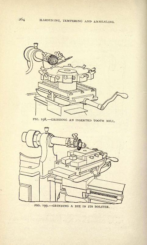
264 HARDENING, TEMPERING AND ANNEALING.
FIG. 198. GRINDING AN INSERTED TOOTH Mil,!,.
FIG. 199. GRINDING A DIE IN ITS BOLSTER.

GRINDING. 265
Fig. 200. Grinding a snap-gage in a vise bolted to the grind-
ing table. All kinds of surface work, such as straight edges, snap
FIG. 2OO. GRINDING A SNAP GAGE.
gages, punches, calipers, test blocks, etc., may be easily and quickly
ground in this fixture.
Emery Wheels Their Use.
The emery wheel consists of grains of emery and a com-
position called the texture which binds these grains together.
In regard to the size of the grains the wheel is said to be
fine or coarse in grade. In regard to its texture it is called hard
or soft.
To distinguish the grades, they are numbered from the di-
mension of the meshes through which the grains pass.
Thus grade 10 means that the distance between the wires of
the mesh is 10 to the inch.
Some of the substances used to hold the grains of emery
together are hard rubber, shellac, ordinary glue and a mixture of
linseed oil and litharge.
The relative hardness of the texture is indicated by letters.
Thus, A indicates a soft wheel ; B, a harder wheel ; M, medium
wheel, and so on.
The vitrified emery wheel is made with a cement which con-
tracts slightly while cooling, leaving small pores or cells throughwhich water introduced at the center is thrown to the surface bv

266 HARDENING, TEMPERING AND ANNEALING.
centrifugal force. This flow of water operates to carry off the
cuttings and the detached emery.The grade and texture of the wheel in certain kinds of work
is fairly within the following limits :
Wheels of coarse grain and hard texture are suitable for
rough grinding such as the smoothing down of protuberances
and in other rough work in which accuracy and finish are not
required.
Wheels having medium grains and hard texture are service-
able in grinding lathe tools, for gumming saws, etc.
Wheels with medium grains and soft texture are suitable for
free cutting on broad surfaces of iron, steel or brass.
Wheels with fine grain and soft texture are suitable for grind-
ing fine tools, such as milling machine cutters for which the
duty is light, but the demand for accuracy imperative.
One of the important conditions of accuracy is that the wheels
vary in the least possible degree in shape or diameter from start
to finish in a series of cuts.
The wheel with fine grain and hard texture is suitable for
smooth grinding on soft metals such as cast-iron or brass.
A wheel glazes or gums if its grains are held too long by its
texture.
The ideal duty of a wheel consists in having its grains dis-
placed as soon as they become unfit for further service.
As the wheel in use wears out of true, it can be trued by a
little black diamond point, and if very accurate grinding or a fine
finish is required, the diamond should be carried across the sur-
face of the wheel by the long slide.
If it is required to do heavy cutting, the emery wheel should
be trued at a comparatively slow speed.
If the wheel becomes glazed, its surface may be improved bya coarse file or a piece of pumice stone.
Emery wheels should be kept clean and free from oil, andshould not present more than 1-16 to ^ of an inch to the surface
of the work. This provision is particularly applicable to cup-
shape wheels.
If it is desired to put an exceedingly fine finish on such workas arbors, spindles, standards, etc., after they have been groundtrue, a wheel of 80 or 100 grade emery, with not more than
Y& inch face, should be used for taking this finishing cut.
However, very finely finished surfaces can be obtained with a
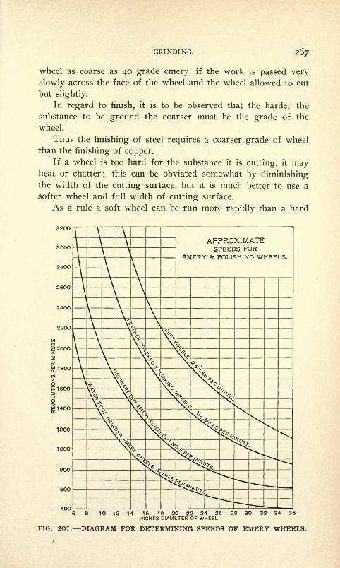
GRINDING. 267
wheel as coarse as 40 grade emery, if the work is passed very
slowly across the face of the wheel and the wheel allowed to cut
but slightly.
In regard to finish, it is to be observed that the harder the
substance to be ground the coarser must be the grade of the
wheel.
Thus the finishing of steel requires a coarser grade of wheel
than the finishing of copper.
If a wheel is too hard for the substance it is cutting, it mayheat or chatter; this can be obviated somewhat by diminishingthe width of the cutting surface, but it is much better to use a
softer wheel and full width of cutting surface.
As a rule a soft wheel can be run more rapidly than a hard
APPROXIMATESPEEDS FOR
EMERY & POLISHING WHEELS
600
40010 12 14 16 1R 20 22 24 26 28 3O 32 34 36
INCHES DIAMETER OF WHEEL
FIG. 20T. DIAGRAM FOR DETERMINING SPEEDS OF EMERY

268 HARDENING, TEMPERING AND ANNEALING.
one without changing the temperature of the work. Accord-
ingly there is an advantage in- two speeds for the emery wheel
spindle.
For internal grinding the wheel should be softer than for
external grinding, and the work should revolve so as to give the
wheel opportunity to do its work.
There can be no hard and fast rules for the speed of emeryand polishing wheels since there is so great a variety in the
nature of the work to be done, but a peripheral speed of about a
mile a minute for ordinary emery wheels is commonly regarded
as good practice. For water tool grinders the speed is usually
about two-thirds that of dry grinders while on the other hand,
polishing wheels are generally run at about one and one-half,
and buff wheels at twice the speed of dry grinders.
The diagram, Fig. 201, affords a convenient means for deter-
mining the revolutions that will give the above speeds and will
be preferred by many to a table of figures. It is necessary only
to trace a vertical line from the figure representing the diameter
of the wheel to the proper curve and from the intersection point
to trace a horizontal line to the figure which will give the revolu-
tions per minute.
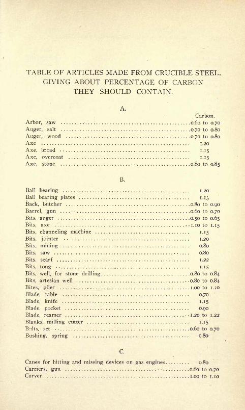
TABLE OF ARTICLES MADE FROM CRUCIBLE STEEL,GIVING ABOUT PERCENTAGE OF CARBON
THEY SHOULD CONTAIN.
A.
Carbon.
Arbor, saw 0.60 to 0.70
Auger, salt 0.70 to 0.80
Auger, wood 0.70 to 0.80
Axe i.20
Axe, broad 1.15
Axe, overcoat 1.15
Axe. stone 0.80 to 0.85
B.
Ball bearing 1 .20
Ball bearing plates 1.15
Back, butcher 0.80 to 0.90
Barrel, gun 0.60 to 0.70
Bits, auger 0.50 to 0.65
Bits, axe . i.io to 1.15
Bits, channeling machine 1.15
Bits, jointer 1.20
Bits, mining 0.80
Bits, saw 0.80
Bits, scarf 1.22
Bits, tong 1.15
Bits, well, for stone drilling 0.80 to 0.84
Bits, artesian well -0.80 to 0.84
Bites, plier i.oo to i.io
Blade, table 0.70
Blade, knife -. 1.15
Blade, pocket 0.90
Blade, reamer 1.20 to 1.22
Blanks, milling cutter 1.15
Bolts, set 0.60 to 0.70
Bushing, spring 0.80
C.
Canes for hitting and missing devices on gas engines 0.80
Carriers, gun 0.60 to o./o
Carver i.oo to i.io

2/O HARDENING, TEMPERING AND ANNEALING.
Carbon.
Centers, lathe 0.80 to 0.90
Chisels for cutting files 1.20
Chisels, chipping . i.io
Chisels, clay 0.80 to o.<x>
Chisels for hot work. 0.60 to 0.70
Chisels, railroad track 0.85
Chisels, blacksmiths' cold 0.85
Chisels, stone cutters' 0.80 to 0.85
Chisels, wood working 1.20 to 1.22
Chisels, brick 0.60 to 0.70
Claw bars (pulling spikes) 0.65 to 0.75
Cone, bicycle 0.70 to 0.80
Creaser 1.20 to 1.25
Cruciform, drill 0.95 to i.io
Cups, boiler makers' 0.60 to 0.70
Cutters, flue . . 1.20 to 1.25
Cutters, glass . . 1.20 to 1.25
Cutters, milling . . 1.20 to 1.25
Cutters, nail '. 1.20 to 1.25
Cutters, corn stalk 0.80 to i.oo
Cutters, pipe 1.20 to 1.20
Cutters, tong 1.20 to 1.22
D.
Dies, bolt 0.60 to 0.70
Dies, blanking (bottom dies) 0.85 to 0.90
Dies, cartridge shell 1.20 to 1.22
Dies, lever link 0.85 to 0.90
Dies, cold heating 1.15
Dies, cutlery 0.80 to 0.85
Dies, envelope 1.15
Dies, drop forging 0.85 to 0.90
Dies, drop forging, for making table knives 0.68 to 0.78
Dies, hammer 0.67 to 0.78
Dies, horseshoe (cold punching) . 1.20 to 1.22
Dies, glove 0.85 to 0.90
Dies, nail 1.15
Dies, paper cutting 1.15
Dies, pipe 1.15 to 1.22
Dies, rivet 0.60 to 0.70
Dies, shoe 0.70 to o.8e
Dies, silver spoon 0.85 to 0.90
Dies, silversmith^' 1.15
Dies, tong i.io to 1.18
Dies, wire drawing 1.20 to 1.22
Dies for pointing machine 1.15
Dies for manufacture of files. 0.67 to 0.78
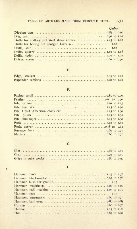
TABLE OF ARTICLES MADE FROM CRUCIBLE STEEL. 2JI
Carbon.
Digging bars 0.85 to 0.90
Dog, cant 0.90 to i.oo
Drills for drilling tool steel shear knives 1.15 to 1.20
Drills for boring out shotgun barrels- i.io
Drills, star i.io
Drills, quarry i.io to 1.18
Drills, twist 1.20 to 1.22
Driver, screw 0.60 to 0.70
E.
Edge, straight 1.05 to 1.12
Expander sections 1.20 to 1.22
F.
Facing, anvil 0.85 to 0.90
Feather 0.60 to 0.70
File, cabinet 1.20 to 1.25
File, cant saw 1.25 to 1.30
File, Great American cross cut 1.25 to 1.30
File, pillow 1.25 to 1.30
File, slim taper 1.25 to 1.30
Fork 0.90 to i.io
Fork, carver 0.58 to 0.62
Furnace bars 0.60 to 0.70
Flatters 0.60 to 0.70
G.
Glut 0.60 to 0.70
Grab 0.70 to 0.90
Grips in tube works 0.85 to 0.90
H.
Hammer, bush 1.25 to 1.30
Hammer, blacksmiths' 0.67 to 0.78
Hammer, bush for granite 1.15
Hammer, machinists' 0.90 to i.oo
Hammer, nail machine 1.05 to i.io
Hammer, peen 1.15
Hammer, pneumatic 0.60 to 0.70
Hammer, ball peen 0.80 to 0.85
Hardies 0.60 to 0.70
Hatchet 1.15 to 1.22
Hoe ...... 0.85 to o.'yo
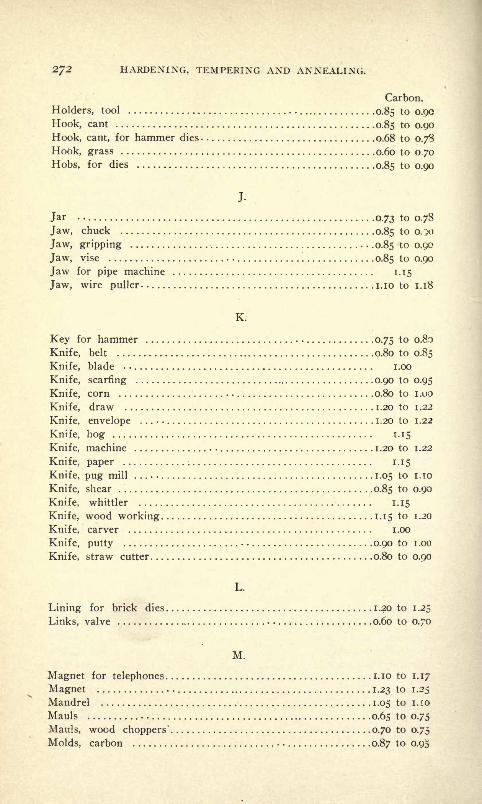
272 HARDENING, TEMPERING AND ANNEALING.
Carbon.
Holders, tool 0.85 to 0.90
Hook, cant 0.85 to 0.90
Hook, cant, for hammer dies 0.68 to 0.78
Hook, grass 0.60 to 070Hobs, for dies 0.85 to 0.90
J.
Jar 0.73 to 0.78
Jaw, chuck 0.85 to 0.50
Jaw, gripping 0.85 to 0.90
Jaw, vise 0.85 to 0,90
Jaw for pipe machine 1.15
Jaw, wire puller. i.io to 1.18
K.
Key for hammer 0.75 to 0.80
Knife, belt 0.80 to 0.85
Knife, blade i.oo
Knife, scarring 0.90 to 0.95
Knife, corn 0.80 to i.oo
Knife, draw 1.20 to 1.22
Knife, envelope 1.20 to 1.22
Knife, hog 1.15
Knife, machine 1.20 to 1.22
Knife, paper 1.15
Knife, pug mill 1.05 to I.TO
Knife, shear . 0.85 to 0.90
Knife, whittler 1.15
Knife, wood working 1.15 to 1.20
Knife, carver . i.oo
Knife, putty 0.90 to i.oo
Knife, straw cutter 0.80 to 0.90
L.
Lining for brick dies 1.20 to 1.25
Links, valve ^ 0.60 to 0.70
M.
Magnet for telephones i.io to 1.17
Magnet 1.23 to 1.25
Mandrel 1.05 to 1. 10
Mauls 0.65 to 0.75
Mauls, wood choppers' 0.70 to 0.75
Molds, carbon 0.87 to 0.9.5

TABLE OF ARTICLES MADE FROM CRUCIBLE STEEL. 273
Carbon.
Molds, brick 0.80 to 0.90
Machinery, crucible 0.55 to 0.65Mattock 0.60 to 0.80
Mower, lawn i.oo
N.
Nut cracker and pick 0.70 to 0.73
P.
Pick 0.70 to o.So
Pick, mill 1.20 to 1.22
Piercers for nail machine i.io
Pinch bars 0.75 to 0.85
Pin, crank 0.55 to 0.65
Pin, eye . 0.75 to o.So
Pin, drift 0.60 to 0.70
Pin, expander i.oo to i.io
Pin, lever 1.05 to i.io
Pitching tool 0.80 to 0.85
Pivot 1.05 to i.io
Planer, stone 0.70 to 0.80
Planer, wood. 1.15
Plates, guard. 0.90 to i.oo
Plates for brick dies 0.85 to 0.90
Plate, throat, for hog 0.85 to 0.90
Plate, tool 0.90 to 0.95
Plow, crucible, for bicycle road scraper 0.85 to 0.90
Plow, ice 0.80 to 0.85
Plug 0.60 to 0.70
Plungers for bolt machine -0.60 to 0.70
Plungers 0.85 to 0.90
Pliers 0.85 to 0.95
Point -. 0.85 to 0.90
Point, clay pick 0.85 to 0.90
Point, piercing 1.40 to 1.50
Puller, nail 1.20 to 1.22
Punch, cartridge shell 1.20 to 1.22
Punch, hot work 0.85 to 0.90
Punch, file blank 1.20 to 1.22
Punch, skate blade 0.85 to 0.90
Punch, washer 0.80 to 0.88
Punch, oil cloth 0.85 to o.oo
Punch, blacksmith 0.80 to 0.85
Punch, railroad track 0.85
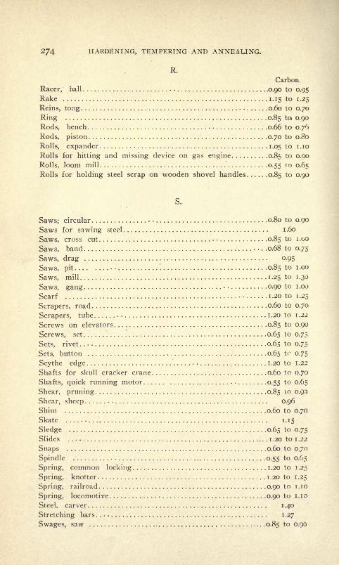
274 HARDENING, TEMPERING AND ANNEALING.
R.
Carbon.
Racer, ball 0.90 to 0.95
Rake 1.15 to 1.25
Reins, tong 0.60 to 0.70
Ring 0.85 to 0.90
Rods, bench 0.66 to 0.76
Rods, piston 0.70 to 0.80
Rolls, expander . 1.05 to i.io
Rolls for hitting and missing device on gas engine 0.85 to 0.90
Rolls, loom mill 0.55 to 0.65
Rolls for holding steel scrap on wooden shovel handles 0.85 to 0.90
S.
Saws; circular . 0.80 to 0.90
Saws for sawing steel 1.60
Saws, cross cut . 0.85 to i.oo
Saws, band . .0.68 to 0.75
Saws, drag 0.95
Saws, pit '. 0.85 to i.oo
Saws, mill 1.25 to 1.30
Saws, gang 0.90 to i .00
Scarf 1.20 to 1.25
Scrapers, road 0.60 to 0.70
Scrapers, tube . 1.20 to 1.22
Screws on elevators 0.85 to 0.90
Screws, set 0.65 to 0.75
Sets, rivet. 0.65 to 0.75
Sets, button 0.65 to 0.75
Scythe edge 1.20 to 1.22
Shafts for skull cracker crane 0.60 to 0.70
Shafts, quick running motor 0.55 to 0.65
Shear, pruning 0.85 to 0.93
Shear, sheep 0.96
Shim 0.60 to 0.70
Skate 1.15
Sledge 0.65 to 0.75
Slides 1.20 to 1.22
Snaps 0.60 to 0.70
Spindle 0.55 to 0.65
Spring, common locking 1.20 to 1.25
Spring, knotter . 1 .20 to 1 .25
Spring, railroad 0.90 to i.io
Spring, locomotive 0.90 to i.io
Steel, carver 1.40
Stretching bars i .27
Swages, saw 0.85 to 0.90
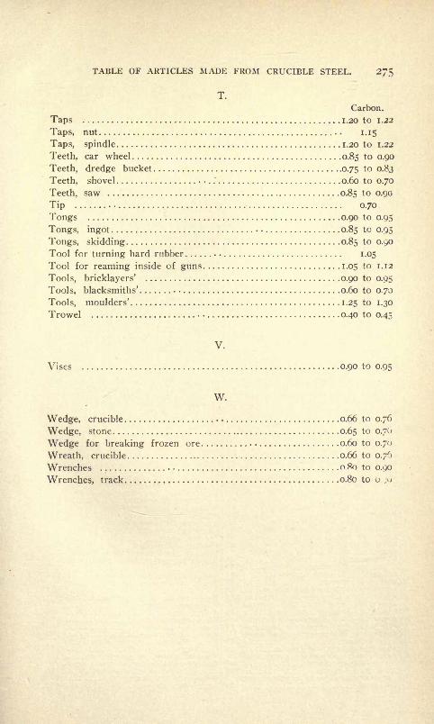
TABLE OF ARTICLES MADE FROM CRUCIBLE STEEL. 275
T.
Carbon.
Taps 1.20 to 1.22
Taps, nut 1.15
Taps, spindle 1.20 to 1.22
Teeth, car wheel 0.85 to 0.90
Teeth, dredge bucket 0.75 to 0.83
Teeth, shovel 0.60 to 0.70
Teeth, saw 0.85 to 0.90
Tip 0.70
Tongs 0.90 to 0.95
Tongs, ingot 0.85 to 0.95
Tongs, skidding 0.85 to 0.90
Tool for turning hard rubber 1.05
Tool for reaming inside of guns 1.05 to 1.12
Tools, bricklayers' 0.90 to 0.95
Tools, blacksmiths' 0.60 to 0.70
Tools, moulders' 1.25 to 1.30
Trowel 0.40 to 0.45
V.
Vises 0.90 to 0.95
W.
Wedge, crucible 0.66 to 0.76
Wedge, stone 0.65 to 0.70
Wedge for breaking frozen ore . 0.60 to 0.70
Wreath, crucible 0.66 to 0.76
Wrenches o.Ro to 0.90
Wrenches, track 0.80 to u. ;<

INDEX.
Accommodate expansion 98Accomplishing fine results with self-
hardening steel 27Accurate sectional casehardening... 139Acid, improved soldering 196Acme standard thread 222Actual pressure against tool 115Adoption of nickel steel for forg-
ings 194Advantage derived from the use of
gas as a fuel 53Advantage in the use of the tools.. 116Advantage of the method 148Advantage of nickel steel for forg-
ings 194Advise the use of cutters of. small
diameters 115Agitating contents of the bath.... 103Air hardening process 22Air tempering furnace 61Allowance desired in machining. . . . 188Allowing die to cool to a black 168Aluminium, lubricant for working. . 196Aluminium, solder for 197America, Crucible Steel Company of 34America, high-grade steel forgings
in 176America, steel produced in by the
crucible method 34American drill rod 14Augular cutters, grinding 232Angular type of milling cutter. . . . 154Animus referred to by Admiral
Evans 178Annealed die and tool steel 21Annealing 38Annealing a small quality of steel. 43Annealing box for small parts 39Annealing chilled cast iron dies for
drilling 43Annealing, furnace-packing the cast-
ings 45Annealing, how to heat for 37Annealing iron castings 137Annealing in the charcoal fire.... 38Annealing low carbon steel bars. . . 136Annealing ovens, heating the 47Annealing steel in the open fire. . . 43Annealing, straightening and finish
ing malleable castings 46Annealing, the effects of water. . . 40Annealing, the proper heat for .... 37Annealing, water 39Annealing white or silver iron. ... 44Anti-friction alloy for journal boxes 197Apparatus used in the Taylor-
White process 116Appearance of fractures of high-
gi-ade steel of various hardness 15Appreciate the advantages of steel
forgings 179Approximate cutting speeds 27Approximate speeds for emery and
polishing wheels 26Area of a hexigon 207Articles made from crucible cast
steel ... 34
Articles, hardening l<mg thin
Articles, tempering thinAi-t of forging with drop hammers.Art of steel treatment, how to in-
struct in the
Arts, Society of ;* *
i
Arranged alphabetically, table ot
tempersAsbestos washersAscertaining the size of pulleys for
given speedsAssorted stock of metal for drop
forgingsAttachment for surface grinding. .
Attainment of satisfactory results.
Attention to the proper selection ot
steel in diemakingAt bottom of thread, decimal con-
stants for finding diameter ....
Authority on the subjectAverage time required to machine
fourteen sheavesAverage speeds for cutting drills.
Axial type of milling cutter
BabbitingBaking enamels and vulcanizing rub-
ber, table of suitable tempera-
122122187
31197
125112
195
19125118
14
21095
114223154
196
tures for casehardening, core
ovens, drying kilns 127, 128Barrel heating machine for harden-
ing and tempering balls, sawteeth, screws, etc
Bath, theBearing rings, hardening five-inch
thrustBelts, horse power of
Bench forgeBessemer steel, casehardeningBethlehem Steel CompanyBevel edges, how to grind a slit-
ting knife withBinds the grains together"Biting in"
Blanking die, hardening a
Blanking or cutting dies, harden-
ing largeBlazing off springsBlind to the temper colors of steel .
Blistering, preventing it while heat-
ingBlows water from the teethBlue, to draw small steel parts
to aBoard with stripes of paint and
names of steelsBoiled waterBone, charring theBone, to char theBorax of commerceBoth die and punch should be
hard *.
Brands of stoel in general use. . . .
Brands suitable for special classesof sheet-metal working
Brass articles, lacquer forBreak like glass
75135
13122565
133113
245265204166
173161176
142154
161
1496134134175
17418
14206157
INDEX. 2/7
Breaking down point 113Bringing slowly to the required
heat 143Buggy springs, to weld 194Bulky portion contracts away from
the frailer portions 168Bunsen burner 122Bureau of Steani Engineering. . . . 194Burning off not necessary 120Bushing, how to grind a hardened
drilling jig 243
Cake of soap, hardening in IllCalculations for determining speeds,
27, 195Capable of withstanding wear.... 142Capacity of steel to cut 30Capital steel 18Carbon and air-hardening steels
deteriorate, when 113Careful in heating and quenching. . 95Careless and unequal hammering. . 159Carnegie Steel Company 140Casehardening as it should -be under-
stood 142Casehardening, accurate sectional. 139Casehardening tools 129Casehardening cups and cones 198Casehardening furnaces 85Casehardening mixture for iron. . . 141Casehardening, Moxon's method for. 141Casehardening, outfit for fine grain. 129Casehardening polished parts 142Casehardening paste 141Casehardening the ends of steel
rails 140Casehardening, very deep 140Casehardening with kerosene 197Casehardening with cyanide of po-
tassium 137Casting chain links 48Castings, annealing furnaces, pack-
ing the 45Castings, annealing iron 137Castings, annealing, straightening
and finishing 46Cast iron, to harden 141Cast iron, to weld 183Cast steel, composition for welding. 183Cause of cracks in dies 167Causes of failure in using high-
grade steel 15Causes the oil to come in contact
with the teeth 146Chain, automatic heating machine
for hardening 85Changes in the grain of the metal. 17Changes of length produced by heat. 32Characteristic appearance of frac-
tures _ 15Charcoal 182Charcoal, annealing in 38Charcoal and bone 133Charcoal, bone and 133Charcoal. Casehardening cups and
cones in 198Charcoal, flame, tempering in 122Charcoal for heating 100Charcoal made from charred
leather 109Charcoal on the top of the lead. . . 153Charcoal, the best 182Charcoal, to caseharden with 140Charring the bone 134Cheapest drop forcings 192Cheanly made cyanide hardening
not 138Checking the temper IllChemical changes in clay 132
Chemical compounds, receipts for.Chief of Ordnance, report ofChucking drillsCircular annealing and hardening
furnaceCircular forming toolsCirculation of a stream of water
upwardCircumstances determine the amount
of shear to giveCitric acid crystalsClassified, milling cuttersClay, heat effects onCleaning the workClearance on tools for brassClosely controlling temperature. . .
Coaly animal matterCoarse appearance of grainCoarse crystalline sectionCoating with tallowCoke suitable for hardeningCollection of plain milling cutters.Collecting the segregation and pip-
ing in the centerCollet spring chucks, hardening. . .
Colors from a light straw to a deepblue
Colors of steel, table of tempersfor tools
Color on steel simply an indicationof heat
Colors, table of temperColors, tempering byColt, Colonel SamuelCombination gas furnace for gen-
eral machine shop workCombined oil and water method. .
Composition called the texture. . . .
Composition for cast steel, welding.Composition to toughen steel
Compounds for welding steel
Consumption of oil smallConcave or straight, how to grind
milling cutters and metal slit-
ting sawsCondition to be prized in steelConditions of the different sections.Confounding cracks with hardening.Consequent contraction and expan-
sion
Consequent sudden chillConstruction and operation of barrel
heating machineConstant reheatingContraction during quenching ....Contraction during coolingContracting excessively in the cen-
ter
Cooling ...'...I.'..'.'...Cooling or quenchingCoppering polished steel surfaces.Copper-over surface nicelyCore of tool left comparatively
softCorliss, George HCost and endurance of forging
diesCost of good steelCost of gas as compared with other
fuelCostly accidentsCounterbores, heating in leadCounterbores. clearance forCounterbores. internally lubricatedCounterbores for cast iron and steelCounterborine:Covering with clayCoyan, M. ECracks in dies, their causeCrescent steelCrucible Steel Company of America.
124108198
81203
162
1749615432
13520411614223
18243100144
180112
136
117128117187
54146265183184183121
2521716
167
168112
779999180
172136100196196
149177
19013
5324106?04204204204431401671834

INDEX.
Crucible steel, table of articlesmade from, giving percentageof carbon they should contain. 269
Crucible cast steel 176Crude and obsolete means for heat-
ing and cooling 50Crude oil for rock drill tempering. 120Crystallizes from shock or vibra-
tion in service 182Cubic contents in inches of a bar
of Iron 207Cubic foot of water, weight and
capacity 105Cutter and tool grinder 227Cutter bits, hardening 159Cutter blades 104Cutter for milling teeth in spiral
mills 155Cutter lubricant 225Cutter lubricant for steel or iron. 225Cutters to remain in oil until cold. 146Cutters, milling, their use 154Cutting and durability qualities of
steel 30Cutting at high speeds IllCutting speeds, table of 138Cutting speeds for cast iron 27Cutting speeds for malleable iron. 28Cutting speeds for steel 30Cutting speeds for brass 30Cutting tools, speeds for 27Cutting tools, self-hardening 27Cutting tools, casehardening 130Cutting thin stock 174Cutting edges of twist drills... . 198Cutlasses, tempering swords and . 123Cyanide hardening furnaces 95Cyanide soap 206Cylindrical casehardening furnace. 85
D
Day, Mr. Charles 113Dead cold 157Decarbonization 99Decarbonized steel surfaces 24Decarbonizes, when steel 52Decimal equivalents of milli-
meters 208Decimal equivalents of fractional
parts of inch 209Deep blue, colors from a light
straw to a 136Deep casehardening, very 140Deep recesses, work with 95Defects running through center of
bars 23Defining the terms 36Definite degree of elasticity, hard-
ening steel to 31Degree to which the article ex-
pands 99Degrees of softness down to a blue
tinged with green 117Degrees of softness below that de-
noted by thermometer 117Delicate pieces, dipping 1
Desirable condition in drop dies. ... 164Desirable tendency 158Determining the correct hardening
process 15Deterioration due to heating 21Device for hardening bushings, shell
reamers, etc IllDiamond tool holder 253Die-blank, reannealing 170Die steel 14Die steel, hardening poor 172Dies cracking while in the forge. . . 168Dies, drop, hardening and temper-
ing 163
Dies from forgings of wrought ironand steel 162
Dies hardening fluids for 172Dies hardening and tempering large
cutting 173Dies spoiled through carelessness
and inexperience 167Dies used for special drop forgings . 187Dies for regular shaped blanks .... 129Difference between hard steel and
tough steel 93Different methods of packing cast-
ings in pots 45! Different quenching baths, their ef-
fects on steel 96|
Difficulties encountered in introduc-ing high-grade steel 181
j
Diminishing width of cutting face . 267i Dipping a long half-round reamer. . 105IDipping at an angle of about 20 de-
degrees 105fluted reamers when hard-
ening 157Dipping half-round or "gun" ream-
ers when hardening 105i Dipping in a strong solution of salt
and water 96Dipping on a rising heat 18Dipping small tools when harden-
ing 156Dipping vertically 101 to 109Disagreeable possibility eliminated. 169Discarding the color method of tem-
pering 119Distortion takes place, when 97Distortion through uneven heating. 97Direct a stream of water onto the
face of the die 164Directions for annealing with gran-
ulated raw bone 136Directions for setting up drop ham-
mers 192Double face mill 146Doubtful steel, to anneal 43Drawbacks to the commercial use
of nickel steel 194Drawbacks to the use of aluminum. 197Drawbridge disc and similar work,
hardening 131Drawing and forming dies, chilled
iron 43Drawing to a temper of 400 de-
grees 122Drilling a large hole in a spindle. . 198Drilling, annealing cast iron dies
for 43Drilling hard steel, lubricant for. 196Drilling or turning aluminum, lubri-
cant for 196Drill entered through a bushing. . . 199Drill with one cutting edge 199Drills for brass 198Drills for standard pipe taps, sizes
of 218Drop dies, hai'dening and tempering. 163Drop forged bracket 192Drop forged crank shafts 188Drop forged wrenches 189Drop forged gear blank 191Drop forging plant 186Drop hammers, forging 185Drop hammers, directions for set-
ting up forging 192
E
Each brand in separate rack 14FTccentric ring, hardening an 98economical use of gas as a fuel.. 53Economy in purchasing cheap tool
steel, no 113

INDEX. 279
Economy in steel}how to obtain... 13
Economy in testing steel before us-
ing 24Effects of heat on steel 97Efficiency and judgment 95Efforts of the government to obtain
steel suitable for large guns. . 177Elastic limit of nickel steel 194Eliminating tendency to warp.... 112Eliminating the possibility of warp-
ing 166Emery wheels, their use 265Empty crucible after using 107English blue 161 I
English works duplicated 179Entering the die edgeways IllEntirely eliminated, segregation and
piping 180Equal sectional area 98Equivalent measures, table of Eng-
lish or American (U. S.) 211Establishments devoted exclusively
to the manufacturing of dropforgings 191
Establishment where thousands ofdies are made every year 167
Evans, Admiral Robley D 178Even grain and velvety appearance. 17Even spacing instead of staggered. 199Even temper 165Expansion of different metals .... 34!E!xact knowledge in the matter. . . 113Exact degree of temper determined
by experiment 118Expansion of gases 31Expansion of wrought iron for each
degree Fahrenheit 33Expansion unequal 32Expansion reamers 201Expert in the art 95Experience in working and using
the different brands 13Experience, skill and sound judg-
ment 95Experience with different grades of
steel 13Experience with crude oil 120Experimental treatment 15Exposing heated steel to a current
of air 20Extensive experiments with, various
metals 194Extensive use to which drop forg-
gings have been put 188Extra cost of annealed steel 14Extra heavy work, hardening 131
Face milling large castings, steelfor 27
Facing 204Features, prominent 227Ferris wheel shaft 181Figuring cost of tools 188Figuring the surface speeds of emery
wheels and milling cutters. . . 207Files, to temper old 160Finding diameter of driven 195Finding number of revolutions of
driver 195-Fmding the area of cylinder. . . 206Finding the capacity of a cylinder
in gallons 205Fine grain, casehardening for 12T>Fine grain, compact 129Finest metal pattern work 49'Finishing cold, hammering hard
and 18Finishing without grinding or clean-
ing 198
Fire and heat, the hardening 99Fire must be free from gas 130Fire of small soft coal 10OFirst advisory board for rebuild-
ing navy 178First annealing does not eliminate
the liability of cracking 168Fixed general rules 18Flange-ended tubes, clamping be-
tween 156"Floating" reamer 201Fluids for dies, hardening 172Fluted cuts too shallow 199Fluted reamers, when hardening. . 157Flux, a good welding, for steel. . . 175Flux, French welding 185Flux, for soldering and welding... 187Force contents into hole 154Formed butt mill 147Forge, bench 65Forged, how hollow shafts are .... 179Forged, steel for tools which re-
quire to be . 176Forging, drop 187Forging, drop hammers, directions
for setting up 192Forgings from steel of high car-
bon 191Forgings for cutting dies 18Forgings, government use of nickel
steel for 194Forgings in America, high-grade. . 176Forgings, steel die 14Forging, heating steel for 18, 176Forging plant, larger and superior
to any in the world 179Forging to shape 18Formed type milling cutter 155Formed face mill 147Formed cutters with steps 203Formulas for sharp V thread,
United States standard thread,Whitworth standard thread . . . 221
Frequent renewal by forging 99From cast iron and steel, to make
edged tools 183From steel, to remove scale 197From 32 degs. F. to 212 degs. F.,
table of expansion 34Furnace, air tempering 61Furnace, circular annealing and
hardening 80Furnace, cylindrical casehardening. 81Furnace, lead hardening 88Furnaces, casehardening 85Furnaces, cyanide hardening 91Furnaces, muffle 93Furnaces, oil tempering 81
Gages, hardening ring 156Gaging the heat by thermometer . . 119"Gall" and "nerve" 95Gang of straight face milling cut-
ters 146Gang of cutters for machining a
wide formed surface 147Gang punch, hardening and temper-
ing a split 173Gas blast forges, their use 54Gas consumption 53Gas, flame, tempering in 158Gas forge for knife and shear
blades 64Gas forge for small work 59Gear cutter grinding 238General directions 252General directions and rules for the
hardening of steel 97
280 INDEX.
General matter relative to malleableiron machine parts
General smith work, hardening mix-ture for
Generation of steam when harden-ing
Getting rid of the center of a hol-low forging
Glue to resist moistureGood and uniform temper ........Good weld between parts, neces-
sary to haveGood welding flux for steel . . . . .
Good steel for good toolsGood tools, good steel for ...'.'.'.Government blueGovernment use of nickel steel for
forgingsGrade and texture of the wheel ....Grade of steel to use for diesGravers, to temperGrain rendered coarse and brittle.Granulated charcoalGranulated raw bone, directions for
annealing withGranulated raw bone, obtaining
colors withGranulated raw bone, how to case-
harden, color and anneal with .
Graphite crucibleGreat flexibility of steelGreat hardness, testing forGreat ordnance works of the Bethle-
hem Steel CompanyGreatest uniformity and maximum
resultsGreen coalGrinder, a small cutterGrinder, Cincinnati universal cutter
and tool
Grinding angular cuttersGrinding, attachment for surface. .
Grinding a bevel cutterGrinding a die blank to the re-
quired angleGrinding a die in its bolster
Grinding a formed tool on its face.
Grinding a gang of mills
Grinding a gage to a given dimen-sion
Grinding a hardened drilling jig
bushingGrinding a hand reamerGrinding a shear plateGrinding a straight edgeGrinding a spiral mill
Grinding a spiral tooth cutter. . . .
Grinding a slitting knife with bev-eled edges
Grinding a snap gageGrinding a taper spindleGrinding a taper reamerGrinding a tap held in reamer cen-
ters
Grinding a taper reamer withstraight backed off edges
Grinding a taper reamer with shearcutting edges
Grinding a worm wheel hobGrinding a twenty-four inch cold
sawGrinding an inserted tooth mill . .
Grinding broad surfaces, wheelssuitable for
Grinding cutters of small diametersand sharp angles
Grinding, cutter and tool
Grinding formed cuttersGrinding, general directions for. . . .
Grinding gear cuttersGrinding, internal
48
160
97
179206161
1621753838
161
19426514
160105130
136
136
13010617524
177
115100254
227232251259
248264248263
250
243241247246231259
245265244241
260
260
261241
237263
266
231227240252238246
Grinding lathe tools, wheels suit-able for 26
Grinding milling cuttere and metalslitting saws, large 23
Grinding mil'ing cutters or sawsstraight or concave 252
Grinding milling machine cutters,wheels suitable for 200
Grinding soft metals, wheels suit-able for 260
Grinding shell counterbores 236Grinding side milling cutters with
a large wheel 230Grinding, shapes and sizes of emery
wheels for tool 228Grinding side milling cutters 233Grinding twist drills 202Grinding reamer blades convex .... 199Grinding the bevel corner on a
double end butt mill 263Grinding the face of a double end
butt mill 262Grinding the face of a small end
mill 261Grinding the sides of an end mill. 262Grinding the face of a straddle mill. 258Grinding the reverse side of a face
mill 258Grinding the sides of a face or
straddle mill 257Grinding, the wheels suitable for
internal 268Grinding, the wheels suitable for
rough 266Ground in special machines 174Ground work, samples of 229
HHammer all sides alike 159Hammer directly over spot rest-
ing on anvil 123Hammering and rolling steel billets 179Hard or soft punches and dies . . . 163Hard or soft wheels 265Hard steel, lubricant for drilling. . 196Hard steel, tempering flat drills
for drilling 160Hard stock, tempering flat drills
for 160Harden in bath with teeth up 154Hardened machine steel parts, to
produce fine grain 139Hardener will be blamed 175Hardening and tempering spring
collet spring chucks 112Hardening and tempering drop dies. 163Hardening and tempering large "cut-
ting" or "blanking" dies 173Hardening and tempering mill picks.. 121Hardening and tempering milling
cutters in water and oil 147Hardening and tempering, proper
equipment for 52Hardening and tempering small
taps, knives, springs, etc 160Hardening and tempering split
gang punches 173Hardening and tempering springs. 161Hardening and tempering round
thread dies IllHardening and tempering, special
instructions for 110Hardening around a hole 156Hardening at different tempera-
tures IllHardening a blanking die 166Hardening cutting bits 159Hardening drawbridge disc and sim-
ilar work 131Hardening extra heavy work 131

INDEX. 28l
Hardening equally all through 99Hardening files 108 to 160Hardening five-inch thrust bearing
rings 131Hardening fluids for dies 172Hardening, heating for 18Hardening, heating in hot lead
for 103Hardening hollow mills 153Hardening in clear oil 173Hardening in solutions 106Hardening, judgment and careful-
ness in 95Hardening large milling cutters. .. 143Hardening large pieces 95Hardening large dies 162Hardening long taper reamers,
103 to 109Hardening metal saws 155.)
Hardening milling cutters in theopen fire 143
Hardening mixtures for generalsmith work 160
Hardening of inexpensive cuttingtools 118
Hardening poor die steel 172Hardening, quenching for 100Hardening ring gages 156Hardening small parts and long
thin parts 104Hardening small saws 159Hardening successful 38Hardening the walls of a round
die 169Hardening steel by petroleum 197Hardening thick round dies 172Hardening very small punches.... 171Hardening very thin tools so as to
prevent warping 158Hardening V shaped milling cut-
ters 152Hardening shell reamers, bushings,
hobs, etc IllHardening, warping of punches in. . 171Hardening, warping of tools in 109Hastings, B 120Heat distributed equally 119Heat affects center equally with
outside 180Heat effects on copper and bronze . 119Heat effects on clay 32Heat, first effect of 31Heat, second effect of 34Heat, the 135Heat, the hardening fire and the. . 99Heating 50Heating according to shape 98Heating and tempering, effects of
slow 97Heating, distortion through uneven. 97Heating for forging 18Heating for hardening 18Heating furnace, the location of the 52Heating in the open fire 99Heating in hot lead for hardening. 106Heating machine for hardening the
edges of mover blades 69Heating machine for hardening
cones and shells 70Heating machine for small parts. . 73Heating machine for tempering and
coloring steel 78Heating machine with revolving
trays 71Heating steel for forging 18Heating slowly to a spring tem-
per 158Heating steel, temperature tell-tales
for 159Heating the annealing ovens 47Heating the steel too quickly 99
Heating the die 168Heating unequally 159Heats, welding 175Heavy work, hardening extra 131Heavy oil 108Heavy springs, hardening 120Highest carbon steel, not desirable
to use 103High-carbon steels, the treatment
of 15High-grade steel forgings in Amer-
ica 170High-grade steel in the smith's fire. 160Hinged plates for hardening saws. 10SHistory of the change from iron
forgings to high-grade steel
forgings in America 177Hob, how to grind a wormwheel
hob 241Hobs or master taps 102Hobson's steel 18Hollow forgings, oil-tempered and
annealed 180Hollow ingot 180Hollow mills, how to temper .... 153Hollow mills, hardening 153Hot water, hardening in 117Hot water, tempering springs in. . 120Horse power of belts 225Howe-Brown steel 18How to caseharden, color and an-
neal with granulated raw bone 130How to caseharden malleable iron. 133How to caseharden rolls, leaving
tenons soft for riveting 132How to dump the work 135How to grind a die blank to the
required angle 248How to grind milling cutters and
metal slitting saws straight orconcave
How to grind a hardened drillingjig bushing
I low to grind a slitting knife withbevel edges 245
How to grind a wormwheel hob. . . 241How to grind a taper spindle 244How to harden a long punch so as
to prevent warping ". 165How to grind a large ring die.... 164How to heat for annealing 37How to restore overheated steel . . . 184How to thoroughly anneal high-
grade tool steel parts 37How to use old bone 138How hollow shafts are forged 179Hubbard's granulated raw bone . . . 130
Illustrations showing various workperformed on a different typeof universal cutter and tool
grinder 257Imperfect preceding operations .... 167Importance of having a good foun-
dation for drop 192Impossible for the operator to be-
come skilled in the art 119Improper means for grinding 168Improved soldering and tinning
acid 196Improvements in the manufactur-
ing and forging of cruciblecast steel 176
Improving poor steel 184Inception of the art 187Increasing the size of the reamer
when worn 19iIndividual testing by the toolmak-
ers 24
282 INDEX.
Information upon air-hardeningsteels 113
Information of value to practicalmen 31
Injurious effects of overheating. . . 18Injuring the quality of the metal . 175Inserted type of milling cutters. . . 198Insure against warping 158Interesting data 114Internal anvil 18i?
Internal grinding 246Internal strains, their cause 175In America, high-grade steel forg-
ings 176,In crude oil, tempering rock drills. 120In expansion and contraction,
amount of force exerted 33In hardening, straightening long
tools which have warped 157In hardening, the use of clay 110In hardening steel, temperature
tell-tales for use 134, 159In U. S. table of different stan-
dards for wire gage used 219In welding, substitute for borax.. 187Iron, a casehardening mixture for . . 141Iron and steel sheets, table of
weights of 214Iron and steel, welding power for. . 183Iron castings, to anneal 137Iron, silver or white, annealing. . . 44Irregular pieces, heating 107
Jessop's steel 18Joshua Rose, M.E 98Journal of the Franklin Institute. 113Journal of the United States Ar-
tillery 206Judgment and carefulness in hard-
ening 95Judgment, experience and percep-
tion in the working of steel . . 31
KKerosene, casehardening \yiui
197Kinds of steel produced in Amer-
ica by the crucible and openhearth process 34
Knives, tempering wood-planer. . . . 122Knowledge and skill employed in
working steel 95
Labitte, M. j lS5Laboratory experiments 182Lacquer for brass articles . 206Lacquer for silver 206Large milling cutter, hardening . . . 143Large power units used in electric
generating stations 176Large ring dies, how to harden... 164Large spiral fluted "hob" tap 19Large tank indispensable 162Large tank provided with perfor-
ated tray 167Latent prejudice against hollow
forgings 181Laving out work 196Lead hardening furnace 88Leaving one of the dies soft 1<i3
Length, measure of 211Liability to crack 101Liability to fracture 15Lime, to clean tank with 20Lineal foot, table of pounds per. . . 215Link Belt Engineering Company. . T13Lodge, Mr. William '. . . 199
Long delicate reamers 110Long, flat or round objects, harden-
ing . .- 105Long knives sure to warp 123Long taper die-taps 103Loose dirt, to clean in 121Low carbon steel bars, to anneal.. 136juowered, modified, tempered, less-
ened 117Lubricant for cutting 225Lubricant for cutting steel or iron. 225Lubricant for drilling hard steel . . 196Lubricant for water cuts 196Lubricant for working aluminum. . 196
MMachine, attachments which are
used on the 256Machine blacksmithing 189Machine, construction and operation
of barrel heating 77Machine parts, general matter rela-
tive to malleable iron 48Machine parts, the annealing of
malleable castings and the man-ufacture of malleable iron .... 44
Machine reaming 201Machine screw taps, table of tap
drills for 218Machine steel casehardened tools. . 129Machines, processes and tools used
in the art 187Machinery steel cutting tools 129Making a tap or reamer cut larger
than itself 195Making welding heats, coke for. . . . 100Malleable department 46Malleable iron, how to caseharden. . 133Manipulated in the fire 97Marking each separate brand 14Master Mechanics' and Master Car
Builders' Association 177Material possessing a very high
elastic limit 181Maximum efficiency 113,116Measure of length 211Measure of surface 21 1
Measure of volume and capacity. . . 211Measure of weight 211Measuring expansion and contrac-
tion 32Medimum cuts and feeds and coarse
thread cutting 27Melting points, table of 124Melting pots 90Metal is improving by forging 191Metal pattern shop of malleable de-
partment 49Metal saws, to harden 108Metal slitting saws 154Metal to expand in cooling 206Method, advantages of the 147Metric and IT. S. measures.. 211M>ssrs. Taylor and White 113Diddle softer than the outside 99Mild steel chips and borax 163Mill picks, bath for hardening 121Mill picks, hardening and tempering 121^nil picks, tempering of cast steel . 121*nil picks, to temper 121Mill should be inverted 153Millimeters and fractions of milli-
meters, decimal eouivalents. . ^08Millimeters of, table 208Milliner cutters hardening V shaned 152Milling wrought iron or steel, lubri-
cant for 204Mininsr and Scientific Press . i?0*Vfistakes and accidents 24Miscellaneous 21 1
INDEX. 283
Mixture composed of equal parts of
charred leather and charcoal. . 180Moderate cost, testing at a ....... 24Moisture in crucible ............. 107Molecules assume the most stable
position ................... 119Molecule motion ................. 32More steam than hole can contain. . Io4Most generally used bath ......... 96Most satisfactory results ......... 119
Moving laterally when quenching.. 102Mower blades, heating machine for
hardening the edges of ....... 69Moxon's method of casehardening. . lilMr. Charles Day ................ 113Mr. P. A. Pratt .................. 41Mr. William Lodge ............... 199Mr. Robert Leith ................ 48Much depands on even heating. . . . 143Muffle furnaces ................. 93Multiple or inserted cutter heads. . 204Muffle regular sizes of ........... 93"Mushet" steel ................. 115Museum of Arts and Trades in
Paris ...................... 33
S
Necessary dies to produce specialdrop forgings ............... 188
Necessary precautions ............ 109'Nerve," "gall" and ............. 95Nicely coppered surface .......... 196Nickel steel forgings, government
use of ..................... 194No nossibilitv of overdrawing ..... 119No provision made for water cool-
ing ........................ 168Not necessary to brighten after the
operation .................. 119Not indicative of a uniform degree
of hardness ................ 118Number of revolutions a drill should
run ....... ................. 202
O
Object of Messrs. Taylor and White 113Obtaining colors with granulated
raw bone 134Of parts of an inch, table decimal
equivalents 209Of solids, table of melting points.. 124O. II. and Bessemer machine steel 42Oil bath 96Oil cools without cracking 123Oil commencing to smoke a suffi-
cient indication 151Oil serves as an indicator of desired
temper 151Oil tempering furnaces 81Oil, tempering in 117Old bone, how to use 133Old files, to temper 160Old Point Comfort 178One of the largest producers of
steel in the world 35Only carbonized portions will
harden 132Open and crystallized fracture.... 17Open fire, annealing steel in the. . . 43Open fire and color test 119Open fire, hardening milling cutters
in the 143Operation of the process 116Operator not familiar with nature
of the steel ] 67Ordering steel for dies 14Ordinary method for tempering mill-
ing cutters 147
Ordinary twist drill with femalecenter 199
Ordinary way of getting rid of thecenter 179
Outfit for fine grain casehardening. 129Output of malleable department... 48Outside very hard 151Overheated steel, to restore 184Overheating when forging 18
Pack in good animal carbon 142Packing and heating the work.... 129Packing in iron box in powdered
charcoal 103Packing the work 143Pameacha raw bone 133Parts produced by drop forging. . . . 187Parts subject to pressure, wear or
concussion 139Parts with thin sides or edges .... 97Paste, casehardening 141Perforated iron pan 159Persistent exposure of fallacies .... 182Phosphorus makes steel brittle .... 130Pieces coming out free from cracks. 95Pieces with holes running part way
through them 154Piercing punches, hardening 104Placing the die in an inclined posi-
tion 164Plain or formed milling cutters. . . . 143Plain water 96Planer knife, tempering wood 122Playing card dies 173Plunging overheated steel into
water 95Plunging into petroleum 198Pointer 184Points to be remembered 52Polished parts, casehardening 141Polished steel surfaces, coppering 196Polishing for tempering 147Poor material cannot be used 191Porter, Mr. H. F. j 90I'otassium, casehardening with
cyanide of 137Pots, different methods of packing
castings in 45Pots, melting 99Powdered charcoal and coke!'. ! 104Powdered cyanide 107Power of burnt bones 142Practical speeds at which tools can
be run 115Practice of the best shops 31Practice, reamer 199Pratt & Whitney 41Prejudice against steel generally.. 178Preparation of the work 44Press tools, use of machinery steel
for 129Press tools, the use of machine
steel for 129Prevent blowing when pouring in
damp boxes 106Prevent carbonization of stock.... 132Prevent cracking 157Prevent warping, hardening so as
to 158Prevent warping, hardening a long
punch so as to 165Preventing unequal expansion 107Process requires a good quality of
steel ....?... 19TProcess very much simplified 117Process which does not reduce the
hardness of steel 117Processes and conditions in con-
nection with each other 31

284 INDEX.
Processes, kind of steel produced inAmerica by the crucible andopen hearth 34
Processes which tend to reduce thehardness of steel 117
Products of the drop forging indus-try 187
Prof. E. Wilson 197Prominent features 227Proper equipment for steel work-
ing 52Proper equipment for hardening
and tempering 52Proper facilities for steel treat-
ment 50Proper heat for plunging the steel. 121Proportion of carbon I/
Proportion of soft core 158Protecting exposed parts 98Protecting teeth from decarboniza-
tion 109Prussiate about to decompose and
dissipate 142Pulverized charcoal 133Pumping oil to annealing ovens. ... 4<Punch or die blank, re-annealing a. 170Punch, tempering a combination
cutting and drawing 173Punches and dies, soft or hard. . . . 163Punches for perforating- heavy stock 170Punches, tempering small 171Punching or shearing heavy metals 163Putting the steel in the bath, man-
ner of 95
Quenching bath 96Quenching for hardening 100Quenching in salt water 161Quenching in a large tank of water 173Quick methods for softening steel. . 43Quoted reports of tests 113
RRadial type of milling cutter.... 154"Railway Review" 140Rails, casehardening the ends of
steel 140Rake of forming tools 204Rapid cooling of the forging 14
Rapid extraction heat 101Rapid method of annealing special
steel 116Rare for an oil-tempered drill to
break 120Raw linseed oil 96Raw potato, sticking in a 158Raw weld joint 14Real knowledge 93Reamer, babbitt 201Reamer, evenly spaced will chatter. 199Reamer, expansion 201Reamer, "floating" 201Reamer for iron 201Reamer for screw machine 20Reamer for brass 200Reamer for steel 201Reamer, formed or curving 20?Reamer, hand ?oReamer, "home made" 1
Reamer, large taper 20^Reamer, Rose 20*>
Reamer, speed for 202Reamer, square 201Reamer, taper, with three blades . . 199Reamer, too much clearance on. ... 200Reamer, when worn, to increase
the size of 195
|
Reamers and reaming 200Reaming a long straight hole 201
|
Reamers, hardening taper 109Reamers, hardening long taper. . . . 1O9Reaming, reamers and 200Reannealing a punch, or a die
blank 170Reannealing tap blanks 42Regular sizes of muffle 93Relation which the elastic limit
bears to the tensile strength. . 11)4
Red hot lead, heating in 106Reduction of strength 98Removing large amounts of stock.. 117Removing technical objections to
the color test 117Removing rust from polished steel
or iron 206Responsibility for bad work in
hardening 159Responsible for bad work 95Results in steel when hardened at
a given temperature 18Required angle, how to grind a die
b'ank to the 248Return to its elastic state 157Ring gages, hardening 156Riveting, how to caseharden, rolls
leaving tenons soft for 132Robert Leith, Mr 48Rock drills, tempering 120Rogers, Admiral John 178Rogers & Hubbard Company 130Rough-down blanks for long tools. . 103Rough test on cast iron 114Round dies, hardening thick 172Round dies, hardening the walls of. 169Round thread dies, hardening and
tempering 111Rose, M. E., Joshua 98Rosin on the blacksmith's forge. . . 1S4Rules for calculating speed.... 27. 1!).">
Rust joints, cement 20(>
S
Salt, heating in melted 96Sal-soda and borax in water 106Sanderson's steel 18Sand bath, ^empering in the 117Saving of 46 per cent 114Schneider & Co., of Le Creusot,
France 179Scientific American Supplement. . . 98Screw and dowel holes plugged
with fire clay 166Screw head slotting saws 159Screw; threads, U. S. S 220Securing the best results from steel 23Secretary of the Navy 178Sectional casehardening, accurate. . 139Sections and shapes of file steel, 16, ITSegregation and piping 180Selection and identification of steel 13Selection of brands and grades of
steel 13Selection of steel of uniform dual-
ity 13Self-hardening brands 18Self-hardening steel cutting tools. . 27Self-hardening steels, treatment of
high-speed 20Servicable slack tub 121Set of hardened and tempered turn-
ing tools 22Set of self-hardening steel cutting
tools 25Setting the grain of steel finer.... 159Setting the fine grain permanently 180Severe usage in the nature of alter-
nating stresses 181

INDEX.
Shear blades, gas forge for knifeand 64
Shell end mills 147Shells, heating machine for temper-
ing and coloring 70Shells, heating machines for hard-
ening, cones and 70
Shrinkage in soft steel 42Skill, experience and judgment in
hardening 118Soliciting orders tor Hollow forg-
ings 181
Slowly cooling the inside 150Slower the temper is drawn the
tougher the steel 119Small articles of even thickness. . . 107Small and medium size springs... 120Small fagots of wrought iron 179Small flat springs 161Small iron parts, to caseharden. . . . 141Small iron parts 141Small parts, annealing box for. . . . 39Small punches, steel for 14Small punches for thin stock 166Small punches, tempering 171Small saws, hardening 108Small spiral springs 161Small taps, hobs, etc., how to tem-
per 160Small work, gas forge for 59Smallest sectional area 98Smoke coming from all parts of the
steel 151Soap or oil in water 20Society of Arts 197Soft machine steel almost worth-
less 42Soft spots after hardening 104Soft spots in dies after hardening. . 1G2Softening steel, quick methods for. . 43Solder for aluminum 197Soldering 205Solid core of lire brick 180Solids, melting points of 125Solution to protect steel from fire. . 106Solution, % opera oil, y2 neat's
foot oil, one ounce rosin 120Solutions are used to some extent.. 143Solutions, hardening in 106Solutions, tempering 124Source of annoyance often over-
looked 154Spacing entirely too close 199Special brands of steel are pro-
ducible 118Special drop forgings 190Special end mill 147Special forming cutter 146Special instructions 110Special instructions for hardening
and tempering 110Special methods, tempering by.... 117Special milling cutter '. . 147Speeds for cutting tools 27Sperm oil 96Spiral springs, tempering small.... 120Spoiling steel by overheating 41Spring chucks, hardening and tem-
pering collet 112Spring temper, heating slowly to a 1f8Springs, to weld buggy 184Spring threading die 96Springs, blazing off 120Springs, bluing ifilSpecial hardening and tempering. . 161Square and hexagon steel, table of
weights and areas of round and 212Stalwart champion of steel 17SSquare reamer 201Standard brands of self-hardening
steel, experiments with 115
Standard pipe taps, table of sizes
of drills for ^18Standards for wire gage in the
United States 219Standard screw threads, table of
United States 220Standard thread formulas for sharp
V thread, United States stand-ard Whitworth thread 221
Standard twist drill grinding gage. 202
Stay-bolt taps 103Steam can escape and water enter. 154Steel, annealing a small quantity of 43Steel annealed die and tool 21Steel bars, annealing low carbon. . 136Steel, a good welding flux for 175Steel, cutting and durability qual-
ities of 30Steel, composition to toughen 184Steel, compound for welding 183Steel cutting rings welded to
wrought iron plate 174Steel, different quenching baths,
their effect on 96Steel die forgings 14Steel forgings intelligently pro-
duced 179Steel for small reamers, taps, small
punches, etc 14Steel for different purposes 14Steel for small punches 14Steel for tools which require to be
forged 176Steel, general directions and rules
for the hardening of 97Steel, how to restore overheated. . . 184Steel in its softened condition 36Steel, judgment, experience and per-
ception in the working of .... 31Steel of special composition 115Steel of a brand which experience
has taught to be uniform.... 118Steel of different carbon percentage 118Steel parts, how to thoroughly an-
neal high-grade tool 37Steel rails, casehardening ends of. . 140Steel, selection and identification of 13Steel, the grain of 23Steel, the heating and cooling of . . . 50Steel, treatment of air-hardening. 21Steel, treatment of annealed die and
tool 21Steel unevenly heated 168Steel worked at a low red heat. . . . 159Steel, to distinguish wrought iron
and cast iron from 197Steel, to blue without heating 197Steel, to remove scale from 206Sticking, mixture to prevent lead
from 1 0SStraight cvlindrical pieces 102Straightening between lathe centers 157Straightening hardened pieces that
have warned 157Straightening long tools that have
warped in hardening 121Straightening on anvil with ham-
mer 1 57Straightening on a block of wood. . 1 ~7Straightening while cold 103Straightening while hot 103Strain occasioned bv ranid cooling. . 180Strains in manufacture 96Stream of water strikinsr the work 95Strength of hollow forgings 18OStretching the chnins 79Striping with different color nalnt. 14Strong brine for the hardening
fluid 172stronsr brine, ouenchiner in 96Stroner close-grained backing 130
286 INDEX.
Strong jet of water in quenching. . 20Stubs steel 166Styrian steel 18Substances used to hold the grains. 266Substances which open the grain . 129Substitute for borax in welding. . . 187Successful hardening 38Successful metal working 20Sudden heat and a cold blast of air 168Suitable specimen for experimental
purposes 15Suitable tempers for, table of 127Sulphur, little as possible 106Supervision of chemists, metal-
lurgists, physicists, and micro-scopists 179
Surface, measure of '. 211Surface of lead covered with
broken charcoal 107Surface scale 96Surfaces, coppering polished steel . . 196Surfaces, decarbonized steel 24Surplus metal thrown out between
the dies while working 190Sword blades, straightening 157
Table of articles made from cruciblesteel, giving about percentageof carbon they should contain. 269
Table of average cutting speeds fordrills 223
Table of cutting speeds 224Table of decimal equivalents of
millimeters and fractions ofmillimeters 208
Table of decimal constants for find-
ing diameter at bottom ofthread 210
Table of different standard for wiregage used in the U. S 219
Table of decimal equivalents of
parts of an inch 209Table of expansion from 32 degrees
P. to 212 degrees F 35Table of English or America (U. S.)
equivalent measures 211Table of melting points of solids.. 211Table of suitable temperatures of
annealing, working and harden-
ing 127Table of suitable temperatures for
casehardening core, ovens, dry-ing kilns, baking channels andvulcanizing rubber 128
Table of sizes of drills for stand-ard pipe taps
'
218Table of thread narts 122Table of tempers to which tools
should be drawn 125Table of temper colors of steel .... 128Table of tap drills for machine
screw taps 218Table of United States standard
screw threads . 220Table of weights and areas of
round, square and hexigon steel 212Table of weights of iron and steel
sheets 214Table of weights of square and
round bars of wrought iron in
pounds per lineal foot 215Taking from the water too soon. . . 101
Tap blanks, reannealing 42Tap drills for machine screw
threads 21 8
Tap steel, the annealing of 41
Taper mill 147Taper of twist drills for clearance. 198Taper reamer with three blades .... 199
Taylor-White process for treatingsteel .... 113
Tell-tale, using the 134Temper colors proof of equality in
degree of heat only 118Temper drawn at leisure 143Temper when due to a second opera-
tion 118Tempers to which steel should be
drawn, table of 125Tempering 117Tempering at special colors IllTempering a combination cutting
and drawing punch 173Tempering flat drills for hard
stock 160Tempering in the charcoal fire.... 122Tempering in oil 119Tempering in the sand bath 119Tempering process which will de-
termine accurately first heat.. 118Tempering rock drills in crude oil . . 120Tempering small punches 171Tempering small spiral springs.... 120Tempering swords and cutlasses... 123Tempering special tools usTempering solutions 124Tempering thin articles 122Tempering wood planer knives 122Temperatures at which solids melt 124Temperatures tell-tales for use in
hardening steel 159Tendency to crack 97Tendency to refine 103Tendency of steel to crack around
the holes 166Tenons soft for riveting to harden
rods leaving 132Test made at the Government test-
ing bureau 182Testing the chain to insure proper
length 49Testing for hardness with a file ... 24Testing for hardness 24Testing for heat 103Testing for toughness 24Testing for trueness 103Testing steel, economy in before
using 25Testing tool steel 23Tests of steel tinder repeated
stresses 182Texture restored by hammering or
rollingfo
... 175That have warped, straightened
hardened pieces 157The annealing of tap steel 41The annealing of malleable cast-
ings and the manufacture ofmalleable iron machine parts. 44
The acme standard thread 222The amount of force exerted in ex-
pansion and contraction 33The best steel for tools 23The bath 96 to 135The castings, the foundry and prep-
aration of 44The difference, tough steel and hard
steel 93The effect of slow heating and tem-
pering noThe effect of water annealing 40The emery wheel used as a metal
slitting saw 249The first effect of heat 31The foundry and pi-eparation of the
castings 44The grain of steel 23The hardening and tempering of
preps tools 162The hardening fire and the heat ... 99

INDEX. 287
The hardening of long slendertools
The heating and cooling of steel. . .
The location of the heating furnaceThe proper heat for annealing ....The slender tools, hardening long. .
The second effect of heatThe terms definedThe treatment and working of well
known brands of tool steel. . .
The treatment of hign-carbon steels
The Taylor-White process for treat-
ing steelThe use of clay in hardeningThe use of gas blast furnaces and
heating machineThe use of machine steel for press
toolsThe work, how to dumpTheir cause, crack in diesTheir use of emery wheelsTheir use, gas blast forgesThick cast iron platesThick round dies, hardeningThick scale results from high tem-
peratureThin and delicate parts, hardening.Thin edges and exposed parts, heat-
ing theThin parts, hardening small parts
and longThread dies, hardening and temper-
ing roundThread parts, table ofThrust bearing rings, hardening
five-inchTime required to machine a given
surfaceTime savedTinning acid, improved soldering
andTires, fastening to wheelsTo anneal doubtful steelTo a blue, to draw small steel partsTo blue steel without heatingTo caseharden without colors
To caseharden small iron parts. . . .
To caseharden with charcoalTo caseharden cast ironTo distinguish wrought iron and
cast iron from steel
To draw small steel parts to a blueTo distinguish the gradesTo heat and cool steel properly. . . .
To make edge tools from cast steel
and ironTo produce fine grain casehardened
machine steel partsTo prevent rustTo remove scale from steel
To temper graversTo temper old files
To weld cast ironTo weld buggy springsToo high welding heatTool facilities not up-to-date. .....
Tool holders and tools, their use. 28,
Tool holders and toolsTool steel, testingTool steel, the treatment and work-
ing of well-known brands of. .
Tools carrying a cutting edgeTools circular formingTools or parts with fine projectionsTools used for bending and form-
ingTools, the best steel for
Tools, working steel forTools, tool holders andTough steel and hard steel, the dif-
ference
103505237
10334
113110
12913516726654
159172
22104
18
104
111222
131
3024
1963343
161179130141141195
1971612350
183
13919620616016018318414
113292523
1818
203108
13023
ir>o
25
93
Tougher effect to steel than bone . .
Toughness, testing forTracy, Mr. B. ETrays, heating machine with revolv-
ingTreatment, air-hardening steel
Treatment, annealed die and toolsteel
Treatment of high-speed self-hard-ening steels
Treating steel, Taylor-White pro-cess for
Tremendous strainsTrimming dies
Tumbling instead of pickling dropforgings
Turn the bulge outTwirling around rapidlyTwist drills, grindingTwisting of long tools in harden-
ingTwo cooling surfacesTwo ways of making a forging hol-
lowTypes of milling centers
U
itUnderstood, casehardening asshould be
Unequal expansionUneven contraction provided for. . .
Uneven heating, distortion throughUniform hardness and temperUniformity of results attained ....United States GovernmentUnited States War Department. . . .
United States weights and measuresUnited States measures of lengths.United States measures of surface.United States measures of volume.United States measures of weights.Universal adoption of the ther-
mometer test
Unnecessary expense in testingsteel
Upward flow of water througharticle
Use for which forging are intendedUse of milling: cuttersUse of various kinds of bathsUsing a punch and die which are
both hardUsing a small narrow broachUsing a soft punch and a hard die
Using, economy in testing steel be-fore
Using scrap steel for malleable iron
Using the tell-tale
Usual methods of hardening air-
hardening steel
13024178
7121
21
113177190
191103146202
158180
179145
142321689510611423108217217217217217
117
24
11219115496
163112163
2448
134
113
Vapors generated in the bath 154Variation from a vertical position. . 109Variation of carbon, effects of .... 114Various defects in ingots 1
Very deep casehardening 140
Very little external heat requiredto draw it 151
Vessels of proper wiath 123
Very small piercing punches, hard-
ening 171
Very small punches, hardening.... 171
Vitrified emery wheel 265
WWalter A. Wood Mowing and Reap-
ing Machine Company 44

288 INDEX.
Warming the work up to a blue. . . 153Warped, straightening pieces which
have ... 121Warping, hardening a long punch
so as to prevent 165Warping, hardening very thin tools
so as to prevent 158Warping of long punches in harden-
ing 171Warping, of long tools in harden-
ing 171Warping, the weaker parts 101
Washington 178Water and oil, hardening and tem-
pering milling cutters in 147Water, annealing 39Water, cuts, lubricant for 196Water for cooling 101
Water, kept at a boiling point.... 168Weights and areas of round, square
and hexagon steel 212, 213Weights, measure of 211Weight of cast iron, wrought iron,
steel, copper and bronze..... 207Weights of iron and steel sheets. . . 214Weights of square and round bars
of wrought iron 215Weights and measures, United
States 217Weld which will not buckle or sepa-
rate in hardening 163Welding composition for cast steel. . 183Welding cast iron 183Welding, flux for soldering and. . . 187Welding heats 175Welding heat for steel should be
higher than that for iron. ... 175Welding powder for iron and steel. 183Welding steel to steel or steel to
iron 175Wetting the fracture 23Wheels, approximate speeds for
emery and polishing 267When a muffle is used 164When hardening, dipping fluted
reamers . 157
When hardening, dipping halfround or "gun" reamers 105
When hardening, dipping smalltools 156
When the proper lieat has beenreached
,. . 153
When worn, increasing the size ofthe reamer 195
Whitworth, Sir Joseph 178Why special instructions are given. IllWilliams & Co., J. H 180Wilson, Prof. E 197Without colors, to caseharden 130Without heating, to blue steel 197"Woodworker" 122Work, cleaning the 135Work, combination gas furnace for
general machine shop 54Work, hardening draw-bridge disc
and similar 131Work, laying out 196Work, packing and heating the. . . . 129Work, preparation of the 134Work, packing the 45Work, to dump the 135Work, to pack the 134Work with deep recesses . 93Working and hardening, suitable
temperature of annealing,table of 127
Working Capital steel 21
Working up and down rapidly.... 154Working steel for tools 159World's Fair, Chicago 181
Worry, vexation and poor work. . . . 17(5
Wrenches, drop forged 1 89Wrong, to apply the term "temper,"
when it is 117Wrought iron for crossheads, and
crank pins 181
Zinc, solder for 187
Zinc, to color or coat 206

Hardening and Annealing Oven, Oil Tempering Furnace,
THE STANDARD HEATINd TOOLS
OF THE WORLD ARE THE
"GAS BLAST FURNACES"AND
"HEATING MACHINES"FOR
Hardening, Tempering, Annealing, and all other
Mechanical Heating Processes.
MADE BY
AMERICAN GAS FVUNACE CO.
23 John Street. New York
SEND FOR CATALOOUF1
If You're a Good Guesser
and haven't anything else to do you may be able
to get right results from the old coke or coal
furnace. Even then, you could make a lot more
money guessing about something else. Every
wrong guess cuts into the profits on the right ones,
and there will be wrong ones yon can't help it.
Ghe Stewart Ga^s Furnace
substitutes certainty for guess work. A certain
manipulation of its valves will give you a certain
result every time. You can depend upon it. It
puts a short stop to the wasting of good steel,
through overheating, and the further waste of
time in doing the work over again. Try a No. 1
Stewart Furnace for thirty days, then send us
the Furnace or a Check for $85.00, whichever
you'd rather.
Don't Forget we Make Various Sizes
and Styles, and wi 1 send youa Catalog for the asking
Chicago Flexible Shaft Co.120 La. Salle Avenue. Chicago. 111.

STARRETT'S
FINE
TOOLSA NECESSITY TO THE MECHANICA LUXURY TO THE AMATEURA DELIGHT TO BOTH . . ...
CATALOGUE FREE
The L. S. STARRETT CO.ATHOL. MASS., U. S. A.
High Grade Crucible SteelFOR LATHES, PLANERS, DIES, PUNCHES, ETC.
Jliien's Special Cire Cumins Steel
FOR LOCOMOTIVE TIRES.
NOTHING KNOWN TO EQUAL IT.
Curner's Patent Iron fibred SteelBest material known for stay bolts, crank pins and piston rods, etc.
Manufactured only by
EDGAR ALLEN & CO., Ltd..Sheffield. England.
EDWIN R. KENT <& CO., Agents,Genera 1 Office & Warehouse : 10 South Canal Street, Chicago, III.
SOLVED AT LASTULCAN ANNEALING BOX and PUTTY
for Machinists, Tool and Die Makersand Blacksmiths. A perfect process for
Annealing all grades of Steel, Mushet, Self-
hardening and CAST IRON. A Die will neverWater-crack, Chip or Spring in hardening brour process. Send for FREE sample and full
particulars.Agents wanted . Size of box,18x10x10
RAY AUTOMATIC MACHINE CO.,
CLEVELAND, O,
The FrdLivklin Model Shop.
SAe FRANKLINModel Shop
PAR.SELL <a WEED,129-131 West 31st Street, ^ NEW YOR.K
Fine Accurate Model and Experimental Work.
The Franklin Gas Engine Castings.% HORSE POWER.
Can be built on an eight-inch lathe with plain slide rest exceptturning the fly-wheels. These we keep in stock turned.
The Franklin Dynamo.50 Watts. Weight 5 1
i Ibs.
Will furnish current as a generator for 6-6 c. p. Lamps (lO-volt).
As a motor it will run one or two sewing machines, or a dental
engine.
Sold complete, partially finished or in the rough. Completeinstructions and blue prints.
IF INTERESTED WRITE FOR CIRCULAR H."

Scientific and Practical BooksPUBLISHED BY
NORMAN W. HENLEY & CO.132 Nassau St., New York, U. S. A.
*#= Any of these books will be sent prepaid on receipt of price to any address In theworld.
j&^=" We will send FREE to any address in the world our xoo-page Catalogue ofScientific and Practical Books.
AMkiiisoii. Perfumes and Their Preparation. A ComprehensiveTreatise oil Perfumery :
Containing complete directions for making Handkerchief Perfumes,Smelling Salts, Sachets, Fumigating Pastils ; Preparations for the Careof the Skin, the Mouth, the Hair ; Cosmetics, Hair Dyes, and other ToiletArticles. 300 Pages. 32 illustrations. 8vo. Cloth $3.00
JBarr. Catechism 011 the Combustion of Coal and the Prevention ofSmoke :
A practical treatise for all interested in fuel economy and the sup-pression of smoke from stationary steam boiler furnaces and from loco-
motives. 85 illustrations. 12mo. 349 Pages. Cloth ?1.5U
Itlackall. Air-Brake Catechism:This book is a complete study of the airbrake equipment, including
the latest devices and inventions used. All parts of the air brake, theirtroubles and peculiarities, and a practical way to find and remedy them,are explained. This book contains over 1,000 questions with their an-swers, and is completely illustrated by Engravings and Three LargeFolding Plates of the Westinghouse Quick-Action Automatic Brake, andalso the 9% -Inch Improved Air Pump. 264 Pages. Handsomely boundin Cloth. Fifteenth Edition $1.50
Grimshavv. Saw Filing and Management of Saws :
A practical handbook on filing, gumming, swaging, hammering and thebrazing of band saws, the speed, work and power to run circular saws,etc., etc. Fully Illustrated. Cloth $1 .00
Griinshaw. " Shop Kinks " :
This book is entirely different from any other on machine-shop prac-tice. It is not descriptive of universal or common shop usage, but showsspecial ways of doing work better, more cheaply and more rapidly thanusual, as done in fifty or more leading shops in Europe and America.Some of its over 300 items and 222 illustrations are contributed directlyfor its pages by eminent constructors : the rest have been gathered bythe author in his Thirty Years' Travel and Experience. Second Edition.
Nearly 400 Pages and 222 Illustrations. Cloth $2.5O
Grimshaw. Engine Runner's Catechism :
Telling how to erect, adjust and run the principal steam engines in theUnited States. Describing the principal features of various special andwell-known makes of engines. Fourth Edition. 336 Pages. Fully illus-
trated. Cloth $2.0O
. im-ha\\. Steam Engine Catechism:A series of direct practical answers to direct practical questions,
mainly intended for young engineers and for examination questiops.Nearly 1,000 questions with their answers. Eleventh Edition. 413Pages. Fully Illustrated. Cloth W
Grimshaw. Locomotive Catechism:This is a veritable Encyclopaedia of the Locomotive, is entirely free
from mathematics, and thoroughly up to date. It contains 1,600 Ques-tions with their Answers. Twenty-second Edition, greatly enlarged.Nearly 450 Pages, over 200 Illustrations, and 12 Large Folding Plates.
Bound in Maroon Cloth $2 .(M)
Hiscox. Gas, Gasoline and Oil Engines:Full of general information about the new and popular motive power,
its economy and pase of management. Also chapters on Horseless Ve-
hicles, Electric Lighting. M;irim> 1'ropulsion. etc. Special chapters on
Theory of the Gas and Gasoline Engine, Utilization of Heat and Efficiency
of Gas Engines, Retarded Combustion and Wall Cooling. Causes of Lossand Inefficiency in Explosive Motors. Economy of the Gas Engine for
Electric Lighting. The Material of Power in Explosive Engines. Car-
bureters, Cylinder Capacity. Mufflers, Governors. Igniters and Ex-

NORMAN W. HENLEY & CO.'S PUBLICATIONS.
ploders, Cylinder Lubricators, The Measurement of Power, The Indicatorand its Work, Heat Efficiencies, TJ. S. I'atents on Gas, Gasoline and OilEngines and their adjuncts since 1875, etc. 412 Pages. Large Octavo,illustrated with 312 Handsome Engravings. Tenth Edition, Revised andEnlarged. Buckram $2 .50
Hiscox. Compressed Air in All Its Applications:Giving the thermodynamics, compression, transmission, expansion, and
uses for power purposes in mining and engineering work; pneumatic-
motors, shop-tools, air-blasts for cleaning and painting, air-lifts, pump-ing of water, acids and oils : aeration and purification of water supply,railway propulsion, pneumatic tube transmission, refrigeration andnumerous appliances in which compressed air is a most convenient andeconomical vehicle for work with tables of compression, expansion andthe physical properties of air. Large octavo. 800 Pages. GOO illus-trations. Price $5 . 00
Hiscox. Horseless Vehicles, Automobiles and Motor Cycles, Oper-ated by Steam, Hydro-Carbon, Electric and Pneumatic Motors:The make-up and management of Automobile Vehicles of all kinds are
treated. It also contains a complete list of the Automobile and MotorManufacturers with their addresses as well as a list of patents issuedsince 1856 on the Automobile industry. Nineteen Chapters. Large 8vo.316 Illustrations. 460 Pages. Cloth $3.00
Hiscox. Mechanical Movements, Powers, Devices and Appliances:This is a new work on Illustrated Mechanics, Mechanical Movements,
Devices and Appliances, covering nearly the whole range of the practicaland inventive field, for the use of Mechanics, Inventors, Engineers,Draughtsmen, and all others interested in any way in mechanics. Large8vo. Over 400 Pages. 1649 Specially Made Illustrations, with Descrip-tive Text. Third Edition $3.00
Inventors' Manual; How to Make a Patent Pay:This is a book designed as a guide to inventors in perfecting their in-
ventions, taking out their patents and disposing of them. Ill) Pages.New Edition. Cloth $1 . OO
K rails*. Linear Perspective Self-Taught.The underlying principle by which objects may be correctly repre-
sented in perspective is clearly set forth in this book, everything relatingto the subject is shown in suitable diagrams, accompanied by full
explanations in the text. Price .' $2 .50
LeVan. Safety Valves; Their History, Invention and Calculation:Illustrated by 69 Engravings. 151 Pages $1 .50
Parsell & Weed. Gas Engine Construction:A practical treatise describing the theory and principles of the action
of gas engines of various types, and the design and construction of ahalf-horse power Gas engine, with illustrations of the work in actualprogress, together with dimensioned working drawings, giving clearlythe sizes of the various details. Second Edition Revised and Enlarged.25 Chapters. Large 8vo. Handsomely Illustrated and Bound. 300Pages $2 . 5O
Reagan, Jr. Electrical Engineers' and Students' Chart and HandBook of the Brush Arc Light System :
Illustrated. Bound in Cloth, with Celluloid Chart in Pocket. 8vo.Cloth $1 . 00
Sloane. Electricity Simplified.The object of "Electricity Simplified" is to make the subject as plain
as possible, and to show what the modern conception of electricity is.
158 Pages. Illustrated $1 .00
Sloane. How to Become a Successful Electrician :
It is the ambition of thousands of young and old to become electrical
engineers. Not every one is prepared to spend several thousand dollarsupon a college course, even if the three or four years requisite are attheir disposal. It is possible to become an electrical engineer withoutthis sacrifice, and this work is designed to tell "How to Become aSuccessful Electrician," without the outlay usually spent in acquiringthe profession. 189 Pages. Illustrated. 'Cloth ?1 .00
Sloane. Arithmetic of Electricity :
A Practical Treatise on Electrical Calculations of all' kinds, reducedto a series of rules, all of the simplest forms, and involving only or-
dinary arithmetic : each rule illustrated by one or more practical prob-lems, with detailed solution of each one. Fourth Edition. Illustrated.
138 Pages. Cloth $1 .00

NORMAN W. HENLEY & CO.'S PUBLICATIONS.
Sloane. Electric Toy Making, Dynamo Building and Electric motorConstruction s
This work treats of the making at home of Electrical Toys, ElectricalApparatus, Motors, Dynamos and Instruments in general, and is de-signed to bring within the reach of young and old the manufacture ofgenuine and useful electrical appliances. Third Edition. Fully Illus-trated. 140 Pages. Cloth $1.00
Sloane. Rubber Hand Stamps and the Manipulation of India Rubber:A practical treatise on the manufacture of all kinds of Rubber ar-
ticles. 146 Pages. Second Edition. Cloth $1.00Sloane. Liquid Air and the Liquefaction of Gases:
Containing the full theory of the subject, and giving the entire historyof liquefaction of gases, from the earliest times to the present. Itshows how liquid air like water- is carried hundreds of miles and ishandled in open buckets. It tells what may be expected from it in thenear future. 365 Pages, with many Illustrations. Handsomely boundin Buckram. Second Edition $2.50
Sloane. Standard Electrical Dictionary:A practical handbook of reference, containing definitions of about
5,000 distinct words, terms and phrases. An entirely New Edition,brought up to date and greatly enlarged. Complete, Concise. Con-venient. 682 Pages, 393 Illustrations. Handsomely bound in Cloth.8vo $3.00
Usher. The Modern Machinist;A practical treatise embracing the most approved methods of modern
machine-shop practice, and the applications of recent improved ap-pliances, tools and devices for facilitating, duplicating and expeditingthe construction of machines and their parts. A new book from coverto cover. Third Edition. 257 Engravings. 322 Pages. Cloth $2 50
Van Dervoort. Modern Machine Shop Tools; Their Construction.Operation and Manipulation, Including- Both Hand and Ma-chine Tools:A new work treatirg the subject in a concise and comprehensive man-
ner. A chapter on Gearing and Belting, covering the more importantcases, also the Transmission of Power by Shafting with formulas andexamples is included. This book is strictly up-to-date and is the mostcomplete, concise and useful work ever published on this subject.Containing about 600 Pages and 600 Illustrations $4.00
\Voodworth. Dies, Their Construction and Use for the ModernWorking of Sheet Metals:A treatise upon the designing, constructing and use of tools, fix-
tures and devices, together with the manner in which they should beused in the power press, for the cheap and rapid production of sheetmetal parts and articles. Comprising fundamental designs and prac-tical points by which sheet metal parts may be produced at the mini-mum of cost to the maximum of output, together with special refer-ence to the hardening and tempering of press tools, and to the classesof work which may be produced to the best advantage by the use ofdies in the power press. Containing 400 Pages. 500 Illustrations .. $3.OO
"Woodworth. Hardening, Tempering, Annealing and Forging ofSteel :
A new book containing special directions for the successful hardeningand tempering of all steel tools. Milling cutters, taps, thread dies, ream-ers, both solid and shell, hollow mills, punches and dies and all kinds ofsheet-metal working tools, shear blades, saws, fine cutlery, and metal-
cutting tools of all descriptions, as well as for all implements of steel,
both large and small, the simplest and most satisfactory hardening andtempering processes are presented. The uses to which the leading brandsof steel may be adapted ar concisely presented, and, their treatment for
Avorking under different conditions explained, as are also the specialmethods for the hardening and tempering of special brands. Containingabout 320 Pages, about 250 Illustrations $2.50


THIS BOOK IS DUE ON THE LAST DATESTAMPED BELOW
AN INITIAL FINE OF 25 CENTSWILL BE ASSESSED FOR FAILURE TO RETURNTHIS BOOK ON THE DATE DUE. THE PENALTYWILL INCREASE TO 5O CENTS ON THE FOURTHDAY AND TO $1.OO ON THE SEVENTH DAYOVERDUE.
JUL 7 1933
^e -1 1939
MAY 1011940
MAR 29 1941
SEP 9
LD 21-50m-l,'33

it 767^4
I 03H4.8