hardfinishing and fine finishing part 2 - gear technology
TRANSCRIPT
Hard Finishing and Finefinishing Part 2
Dr ...-Ing, H. SchrieferC. Hurth, Munich, West Germany
EdUots Note:. Part I of this article dealing with the geometryof gear flanks, kinematics, and drive systems, tools, and com-puter assistance for hard and fine finishing, appeared in our lastissue.
Operating Sequeaoes andMachining Results
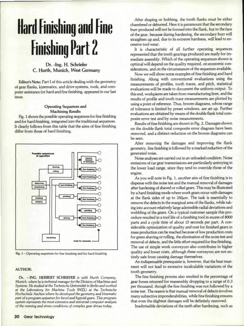
F~.1shows the possible operating sequences for fine finishingand for hard finishing, integrated into the traditienal sequences.It dearly foHows from this table that the aims of fine finishingdiffer from those of hard finishing.
Fig. 1-Operating sequences for fine finishing and for hard finishing.
AUTHOR:
Dr. -ING. HERBERT SCHR1EfER is with Hunh Company,Munich, where he .is technical numager for the Division of Machines andSystems. He studied at the Technische Universitiit in Berlin and workedat the Laboratory for Machine Tools (WZL) at the TechnischeHochschule .Aachen where he developed the geometry and kinematicpart of a program sequence for bevel and hypoid gears. This programsystem represents the moste:xtenslue and universal computer analysisof the run ning and stress conditions of complex gear drives today.
30 'Geor Technology
After shaping or hobbing, the tooth Hanks must be eitherchamfered or deburred, Here it is paramount that the secondaryburr produced will not be formed into the flank, but to the faceof the gear, because during hardening, the secondary burr willstraighten up and, due to its extreme hardness, will lead to ex-cessivetool wear.
It ischaract.eristic of all further operating sequencesrepresented that the tooth gearings produced are ready for im-mediate assembly. VVhich of the operating sequences shown isoptLmaJ will depend on the quality required, on economic con-siderationaand on thedrcumstanees of the sequencesavailable.
Now we wiJl show some examples of fine finishing and hardfinishLng. Along with conventional evaluations using themeasurements of profiles, tooth traces, and pitch, statisticalevaluations will be made to document the wtiform output Tothis end, workpiroesare taken from manufacturing lines, and theresults of profile and tooth trace measurements are plotted byusing a point of reference. Thus, broom diagrams, whose rangeof tolerance is limited by preset windows, are set up. further'evaluations are obtained by means of the double flank total com-posite error test and by noise measurements.
Results of fine finishing are shown. in fig ...2. Damages shownon the double flank total composite error diagram have beenremoved, and a distinct reduction on the broom diagrams canbe seen ..
After removing the damages and improving the flankgeometry I fine finishing is followed by a.marked reduction of thegenerated noise.
Noise analysesare carried out man unloaded condition. Noiseemissions of car gear transmissions are particularly annoying inthe lower load range, since they tend to override those of theengine.
As you will note in fig. 1, another aim of fine finishing is todispense with the noise test and the manual removal of damagesafter hardening of shaved or rolled gears. This maybe illustratedby a hard tinishing mode where work gears occur with damagesat the flank sides of up to 3S0.um. The task is essentially toremove the defects in the marginalarea of the flanks, while tak-ing into account relatively large admissible radial. deviations andwobbling ofthe gears, On a typical customer sample this pro-cedure resulted in a tool life of a finishing tool in excess 018000parts and a. cycle time of about 15 seconds per part, A con-siderable optimization at quality and cost for finished gears in.mass production can be reached because of low production costs~orgIleenshaving or rolling, the elimination of the noise test andremoval of detects, and the little ,effort required for fine finishing.The use of simple work conveyors also' contributes to higherquality and lower costs, although these conveyors are not en-tirely safe from causing damage themselves.
An indispensable prerequisite is, however, that the heat treat-ment will not lead to excessive incalculable variations of thetooth geometry.
The fine finishjng process also resulted in the percentageofgear boxes returned for reassembly dropping to a range of 0.3per thousand, though the fine finishing was not followed by a.noise test. The reason is that manual removal of defects involvesmany subjective imponderabilities, while fine finishing ensuresthat even the slightest damages will be definitely removed.
Inadmissible deviations of the teeth after hardening, such as

L£AD';;-~ -----:-- -=;-::;'i.; ;1 .~- ' .!.' '. ~. '; .~. ..t .' • .. .· .. ..I. ,
• r •••.. . ,..... ... , .." .· ....· .· . ... . .. '" .. .. : ~.. _ -..... .
Rg. 2 -Working example ,offine finishing a gear.
bent teeth, need, however, to be removed before fine finjshingby means ofan automatic two-flank rolling test.
Fig. 3 shows the macrogeometrical results before and aft.erhard finishingw:ith a CBN-()oated tool. It can be seen that hardfinishing will produce an entirely definite geometry ,of toothflanks.
The desired gear flank has a slight profile bearing and facecrowning, and it has been slightly modified at the addendumarea ...In this case, a stock removal per flank of 50JU11will besufficient.
Sinceany~y accurate hard machining process is alwaysthe most complicajedand costly operation in the work .flow ofgear production, this production step should not be used in im-proper extension. A minimization of the required stock removalfrom the hardened Hank is also appropriate for the necessarycase-depth {1I10th mm of case-depth thickness will require acementation 'time of about one hour} and in view of the reduc-tion of hardness caused by the removal of excessive byers at themarginal areas.
It should be' further noted that, for reasons of load eapacity,the machining s.tep in the root fillet should be as small as possi-ble, or precutling should be carried out with the protuberanceentering tangen'tiatlly into the hard~finished flank,
The aim of minimizing the case depth also results from the re-quirement not to core-harden the synchro mesh gearing nor thetooth tips ·ofaddendum modified teeth with an extremely hightip and, consequently, a minimum thjcknessat the tip.
For the example shown 'lite machining time was 48 seconds.As an average, quality grade 5a.cc. DIN 3962 was obtained. Forthe roughness of 'the flanks we have Rzo 3, !Um,R~ = O.4iS
--- ----
Doubl.-fl.ft"- total compo_ite di.llram~_ '
-::.;;;; ;a;;•• ;;;:;;:.·:: .:~:-;. .••• 4 '1 _., ••••••••......................... ,. - .•:::I:::=:::::;.:::~;:::: : ; . . .
.......................... t ••• .. ••_ _ , •••••• _.. • I............ .. .._ _. . ............ ........... .;:r:::~:::::!::::!:;:::::;!:~::~··::: ...-~.. - ..~ ----....... ..;;;..-;:...;;;;;;:~:;:-:;;:..~.:; :;. ...............-- ~.. .................................... .. . ..................... _ ....................................... ,.~... . .::::::::.; .,-;.....::~..::::::.... .. ..:,-::::::-.::::::::::;;:::e;;.;;: :~:; - . .~ &......................... .. .. .-_ -- - , .EF.;:;~:i!:;r!!;;r=!!:::::!;;:~;::..: ~... :~:.. :
- -- - - - -- - -
·1,,,
Itl, profilerh
Fig. 3 - Profile and lead dj"gr~ms before and ~fte1IiMd fi!lishin,g.
~m. The variation of the measuremen! over flanks is less than20,.an.
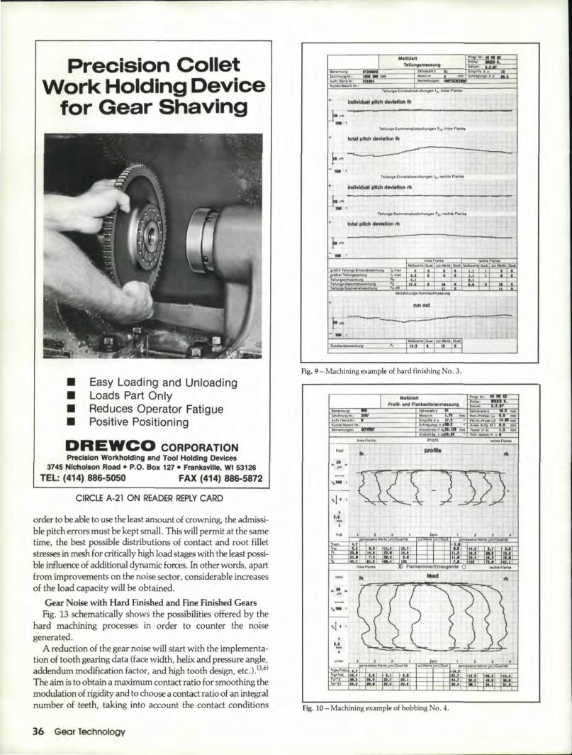
Results from hard finishing are presented in Tables 1 and 2together with profile, lead, and pitch measurement records. (SeeFigs. 4-12.)
In the middle of the profile and lead f'ecords the requiredmodificat:ionsa:re given.
INovember/December 1989 31
SE,PELG,EAR GRINDE,R........--------..... igh Production - Accuracy - .Re/iabi/it
MODEL FKP_32~1O IMMEDIA IE DEUVERI,ES
.' MAX. DIA. 13.58" • AUTOMATI'C GRilNDING CYCLES
• D. P. RANGE
• !HELIX ANGLE
48-4 '. FASSLERO..5.A. DRESSING
• PRO:FILEMODIFICATIONS
• WHEEL DIIA. 17.7" • ALLEN BRADUEY PlC
Iinstallations Throughout The US.
Exclusive Import.er Por INorth America
PEELeo MACHINE TOOtS, I.NC.,805Albion Avenue • Schaumburg, IL 60193-4522
(312)351-.277.2
SALES FAX:(312)351-6930 SERVICE
See us .at U,e AGMA Gear Expo, Booth #124.
CIIRCLE A-18 ON READER REP~YCARD

-•
II
w.,.1 IIIIft I III..I- ,
-•
Rg. 4 - M!thinillg eltiImple of hard finishing No. L
TaMe 1Machining Examples of Hard Finishing
Frg.14IlS Fig. 16111 Fig. 18119 Fig. 20121122Eumplrl Ex;omple2 Example 3 Example 4
Number of teeth 41 32 Sl 31Module 2.54 1.15 .2 1.75Pressure angle 20' 15· IS" 17.5Hdl"mglr -11 -15.15" 29.S· -3O.SFiKewidth 21.5mm ]·/>.7mm I1mm 16.5mmApplication Is1Sprrd .3rdsprrdl lsi speed 51h spe«!
collarMOOinc Lion 01 It"rh 12"m !h tip ..,Hef In!rh !h/rhpr~u~ ..ngl~ slanting rh sl ..nling lip I\ft,e/ lip ,relief
by4"mProfile crowning In/,m 2jlm Ihl,h31'm Ih/rh.3l'm lh/rhljlmModiflcallon of Ihl0jlm Ihl5l'rn Ih81'm In 71'mhellx ilngle rhOl'm rh 12jlm rh lace mod. rhOjlm~;!dCTownirrg lhlm 2"m Iklrh 4 lim !hotI'm IhlrhSl'm
rh 2 I'mCulling material corundum CBN corundum CBNBonding + cerami nickel + ceramic nickel +blank whl!:t!l, '1""lwh~l whl!:t!J steel wheelPl'flnachinin~ precsh ..ved shaped hobbed hobbedslock rernoya!//l<ink 55"", 45 "'" so I'm SO"moOu..Jit)'''«'DtNl96.2 5 lob 5 6 6Surface roughness 2 I'm 1l'mw;th 3,.m 4/!mRm subsequent
line finish.Machining lime b1s«. 69 sec. 7ls«. 49SK.Too.! life I perdre-ssing cycle JOo!! total 8,000 of! 2S off total 1, JOO off
umber of dressingcyclrs 35011 - JO'off -
um~r M R'Ca.alingspertool - 5 - 5
Experience with successful modifications for noise reductionin wide load ranges demonstrate that what matters is corrnctl,ychosen modifications of the pressure angle and helix..a.ng1 withthe least possible crowning, As a rule, the drive flank and thecoast flank should be modified diffel'ently. Flank corrections inthe lead-in and lead-out area are carried out d gressively. In
Table 2Main Characterlsties of
Fine Fiinishinga:nd HOII'dFinishingFine finishing Hard finishing
Machineconcept
• development from modularystern 01greenshavlng
machine
• connected lo~d 12 kVA
• part is driven and brake lorceapplied to tool
'. stored-progt"m eorurol
• no additional motlens duringmachining
iii sa,me
• connected IcadlS kVA
• part and 1001 are kln~m~1 i .ally locked 10 a mol I r artransmission
'. C 'C controlled, two aArS
'. radial inJeed
I. sameTool '. ~"ternal gear, outsidediameter 2.lO mm
• corundum. synthetic resinbonded
• repeated dlftSing withdjamond dresser i pQSSibl~
• number of pieces pt', tool lifedep"nds on stock removed.number of work Erar teeth,hardening distortion. radialdeviation. quallty 01prema.chining, requIrementson quality !VOId. to beobtme<!
• example d 1.0011ifc:m - 2.2, Z - ,35
slock removal ,2 + 15 I'mdressing cyd~l 00 + 400 p.1Irhnumber 0.1 gears per 'ioolilleup to 8000 pes.
• corundum, ceramr~ bondi!'\ilor CBN coal:fd
• sam'!
I. s.me-stock removal 40 ... 150' I'mdressing cycles ] 5 + 6(1 patllnumber of ears ~r oeramltool. up' 10 1200 pes. number01 gt.us per CB 1001. up 1010,000 pc•.
Feed andInfeed
M05hingcondlrlons
• no longitudinal feednoinfeedconstant distance bet ....eeneenter lines
II continuous motion withouttrace 0.1 generated cut andfeed
'. crossed-axes angl.10·45'
'. single-flank machining byreversing sense of rotation
Ii'sameradial infeed
Part '. module 1.2 + 6 mm
'. oUfside diameter20+ 280mm
• Width of tooth l1;onkuploSOmm
• helix angl,e O· and ;I; 40·
'. 1 + 4 mm
'.4:5 + 250mm
'. uplol!imm
II same
Toothgeometry
• Rm srna ller than 211m po ible as required:'• .Rm - 2 10 S I'm (cwol!mcl• ,R", - 410B/LfTI (CBNl
• depending on quality ofprecutting
• on an average belt •• Ih.nquality srack 6 ace, DiN 3961
M.a.inir\g • "boul 0.5 min.tlme
• <kpendin./lan ~ininllcritena, aboul 1 min
November/December1989 3·3,

JEll: Robbersthat tnake sense
.' Why purchase a used gear hobber when youcan have a flew JElL automatic cycle
gear hobbing machine for less money.• 5 sizes available with hobbing capacity of
26"to 71"• Contact: HERMES MACHINE TOOL CO~•INC
5 Gardner Road· Fairfield, NJ 07006Tel.: (201) 227-9150 • Fax: (201) 227-9364
r------~------------------------~Cur our ami mail IOOUY[0:
HERMES· 'lACHINE lOOL Co. I C.5 Gardner Road •. Fairfield. .] 07006
'::) Please send me adduumal informanon on rhe JEI L. withcapacity: _
Namc ___
Company ___
~~~----------------Phone _
~------~------------------------~CIRCLE A·19 ON READ.ER REPLY CARD
Bring in new customerstor your business by advernsmq ,in
GEARTECHNOLO'GY,:1 The Journal of
Gear M'anufacturing ,.
I Mllbt.t1 ~HI ... _
Tillh"I~IInMa;unt t--:= ,I
ZJI'InR«N~ III Phi '"- '"
-I ==- --:......I~··~
}...- ,
- ,
-~ ..- .
II rIO1111 i
7. ..---1.1,
--l'-- I
, -Fig. 5 - Machlningexample of hard finishing No.1.
....
.'...VoI- 1
Fig. 6-Machinin8 example of hard finishing No.2.
I_H
TII! _to_-_ . .
• ad!-
Ill ...'
+ - ..... - ..
r-- ,llllilU'9'B"rrt "c .... !t.I!IIIlIiIiII,...
'~ --,pI!do_1'IIJ-..;, -.. tooIol, pIIcII_ rh
1ft- '
~T
..... DIIIrr~-""'~",,"=-=::--~~------""''''-----o_-_.......;.......;;.::-;.:;..;.!':.J,--? --
••
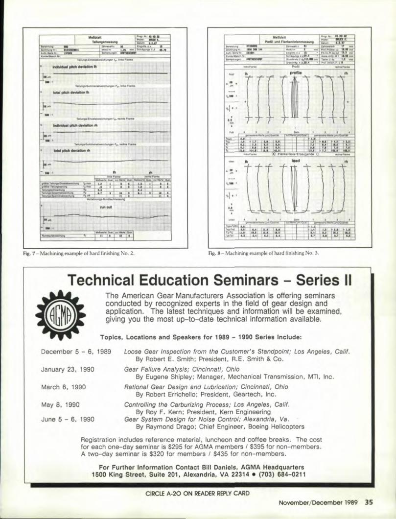
Fig. 7 - Machining example of hard finishing NQ. 2. Fig. 8- Machining example of hard finishing No.3.
The American Gear Manufactur,ers Association is ,oUeringseminarsconducted by recoqnized experts in the field ,of ,gear design andapplication. The latest techniques and information willi be examined.,g,iviingyou the most up-to-date technical information available.
December 5 - 6. 1989
Topics" Leeatlens and Speakers for 11989'- 1990 Series Include:
Loose Gear fnspection from the Customer's Standpoint; Los .Angeles, Calif.By Robert E. Smith; President. R.E. Smith & Co.
Gear Failure Analysis; Cincinnati, OhioBy !Eugene Shipley; Manager. Mechanicall Transmission. MTI. 'Inc.
Rational Gear Design and Lubrication; Cincinnati,. OhioBy Robert Errlchello; President, Geartech, Inc.
Controlling the Carburizing Process; Los Angeles,. Calif.By Roy E.. IKern; President. K'ern Engineering
Gear System Design for Noise Control; Alexandria, Va.By Raymond Drago; Chief Engineer. 80eing Helicopters
Registration incl'udes reference material, Iuncheon and coffee breaks. The costfor each one-day seminar is $295 for AGMA members 1$395 for non-members.A two-day seminar is $320 for members 1 $435 for non-members.
January 23,. 1990.
March 6. 19'90.
May 8, 1990
June S - 6" 1990
For Fur*her Iinformation Contact Bill Oanie'I!s:,AGMA Headquarter,s1500 King Street, Suite 201" Alexandria, VA 22314 • (703), 684-0'211
CIRCIJE A-20 ON READER REPLYCARONovember/DeoemtJer 1989 35
Preclislo:n ColletWOirk H'old'ing Device
for GearShav'ing
Easy Loading and Unl:oadingLoads Part On IyReduces Operator FatiguePositive Positlonlnq
D:REWCO CORPO,RA.TIONPrecision, Workholdlng and' Tool Holding Devices
3745 Nlcho.lson Road • P.O. Box 127. Franksville, WI' 53126TEL: (414)886-5050 FAX (414)886-5872 i
CIRCLE A-21 ON READER IREPlY CARD
order to be able to use the least amount of crowning, the admissi-ble pitch errors must be kept small. This will permit at the sametime, the best possible distributions of contact and root filletstresses in mesh for critically high load stages with the least possi-ble influence of additional dynamic forces. In other words, apartfrom improvements on the noise sector, considerable increasesof the load capacity will be obtained.
Gear Noise with Hard. Finished and Fine Finished GearsFig. 13 schematically shows the possibilities offered by the
hard machining processes in order to counter the noisegenerated.
A reduction of the gear noise will start with the implementa-tion of tooth gearing data (face width, helix and pressure angle,addendum modification factor ,and high too th design, etc.). (3,6)
The aim is to obtain a maximum contact ratio for smoothing themodulation of rigidity and to choose a contact ratio of an integralnumber of teeth, taking into account the contact conditions
36 Gear Technology
M,&:bl,u
1l1li,.144Ao.IflrJs.ri.INr
K.iIIIdIIINuc~Nf.:
+
+
.. I
+
+
I~n~ ~Lm~. ,.c;i'olli FWi'I(, I
~""".O ... t:tIJLWIrl.Ou.l_I~iIIi)waJ.IULfMlUlOiuoI
.......,. :ouatiill.WIiirI 0iJaI.RuMt&ull.tIWtII/;ilwng , ~~ __ L-
fig. 9 - Machining example of hard finishing No, 3,
..........fJl!.linAlrblllAl_i.l~~a Mi • _
'MI r.~"":1!1~P10f --.ct. .~__•
r.:;I'IlijlfWlUi...,II
•
ZR\ -]J)J.•~ ...... ti
II.U,' -II
I,"",,,!~ Fllnk8n~lnII!/Erzerugl!lfJdfl' 0- II
~....'""V._ I
.. ~ bi'oti I :IiM'HI .fI6I1 uaJ~ wI. I I • _~_ III I ~t'l
fig. lO-Machining example of hobbing No, 4,

I IM.IbI.t:t "' , ..
_ """ FIonkonlW. ...... __ Pwooc.w_ ..• .......... ~
10. . , - PJgt MJIMr L.. ~.i.litlrJIildlIIIiI=- , ~n_.:_~~~~KlNlJIMMaIt ..... '.~ ~21 - t..... ~111 -« 1I'ruI~'IiI;"'4' "
.... 1'WiiIiIo Pool!! 1'Kt!W~
-! ~III '"p". ~ f[CmITU}...-,..-.I---,I it =1
•a..-•... . ! , . .... , I"
.~ m <\II
,,I. •II ~~;I • o. j '. 'II
I -- lO Flan""""nJoJ Ermtgti>IIo 0 ..an.,1IinU- III IMd III
~. ;!II TTT TI ""' \"...-
~'_I i
'I--- I I~I•.i ,~ , 1J.,I'
~~~.~! 1;.lL.!. ""'-I, ,":, --- • ,. I I • " 1 ",.;l.....- u . ., ~:lt, ,
Fig. 11- Machining example of hard finishing No.4.
I TeIIunprMIllln;g:-. ..~ .
T..II!ung~f'""NriIl.f1&ni1
_1~_1h --'. I
+
- , Itr,
~,o...i .rwl.1!IWW1~QaI. ~,c..I 1M'"
tH
+II!!! ,!!!II
.. ,~ JijI .... OioIIII
UI.. '. 1,
Fig. 1J - Machining example of hard finishing No.4.
JAMES ENGINE'ERIING_
11707 McBean DriveE,I Monte, California 91732
(818) 442-2898 Booth #234
* Compact Design: Ideal for cell envronrnerus.
* Durable: De~lgned to meet production demands.
* Fast set up and operation: Most set ups made In less than I minute wnhryplCal cycte limes of I minute Of less
* Portable: WJlh optional can it can be moved from WOf~ station towork station.
* Fast chucking: OUickly chucks most par~ WI[hOut costly and timeconsuming speCial tOOling.
* Vernier Scares: Vernier scaleson the adjustmem axes allow quick andconsistent repeat setups.
* Modular Design: Opncns Install and remove In seconds.* Versatile ~~~; With tile optional equipment practIcally any Iype or
gear and edge finish can readily be achieved
CIRCLE A-22 ON READER REPLYCARD
under load. The modification band width should permit a con-figuration of the tooth pattern that wiD allow no erratic varia-tions of rigidity ..Only a defined tooth bearing development winpermit a modification of flanks for a wide-band load range,Otherwise heavy noise win be generated mainly in the partialload range, since the rather unyielding partial-load tooth patternwill result in a contact ratio ofa non-integral number.
At the same time, the tooth contact pattern should have suchan ease-off geometry that neutralizes deviations caused bymanufacturing and faulty meshing due to the load is minimal,
A conclusion drawn from these circumstances is that onlyatooth flank design specifically adapted to the possibil.ity ofadefined tooth pattern will be able to make full use of the essen-tial advantages of hard finishing .
The practical procedure for defining the modificadons can beascertained by checking the tooth pattern, as with copper-platedgear flanks, with the gear unit in actual operation.
November Ioeeemeer 198937'

Flank Tooth 'Composit.modificatio:n contaGt awl.tion
De'forml!lUons ofhousing,shafhi.bearings underLQild, thermalinnuences
Tooth distortionunder load,,meshing impact,pitch error
Dls.tributjon ofpressure underload, ~tter DfproductionIoleranC(ts
T<>P<>Iegi""lIyoptimiztJd n'ankgoo-melt)'
Fig. 13~ Systematic diagram of superimposed modifications of flanks for noisereduction. .
--.om'V
5 mV/Div.
IE. 45 mV
mV/'Di¥.
+: I - - - - r - -lies (tonesloo ...
I
Fig. 14 ~ Frequency analysis of the airborne noise of green shaved gears.
&,_ noI .. /CIoc'_·-",fundamental' !requency:I ... 800 Ii> _ finiol>e<l, '01 rnodj!lcation
4D mV
5 mVlOr..
:8-35 mV
mVIDiv.- - --'-
I1 ...... -T--T-- hormon .... (pure _.
+ 1 I I I +1 I1 I
1 --I 'IlIIrrow-banded genention
1--1 I-.~ ~
;JV IJW~ J\.~,
_, 1.6 KIt. 4.8 KHz 10!t~800 1Hz 2.4 KHz
Fig. 15 - Frequency analysis of the airborne noise. of hard-finished gears (firstdesign of modifications).
38 Gecr Technolog,y
+
The first step is to define the modifications of the helix andpressure angles.
These modifications differ for the drive and coast Hankgeometry according to the deformation behavior of the systemof shafts and bearings, as well as of the gear housing.
Angle modifications are defined for a characteristic load stageof the gear set by evaluating the tooth patterns. According tearecognizable trend, a flexible grinding process is used to providegears with modifications that will cover the estimated area ofmodification. These tests will be continued until satisfactory con-tact pattern (no noise behavior) is achieved.
The second step is to define modifications which will lay downthe band width of the admissible load range and which willneutralize a scatter of deviations caused by manufacturing on ac-count of production tolerances. Mainly,this would concern pro-file corrections in the lead-in and lead-out areas or addendumand dedendum areas and superimposed crownings.
The procedure is the same as explained above, though in thiscase the preset load range will be investigated step by step.
Effective modifications for noise reduction are characterizedby an unerring choice of angle modifications and by the leastpossible superpositions of profile corrections and crownings inthe range of a few p.m.
The effectiveness of these modifications will essentially dependon the very dose scatter of production tolerances of the gears.For instance, pitch, profile, and helix angle deviations couldreduce and even neutralize the effect of such modifications ...
In the following, a noise reduction on a test rig will be de-scribed by way of example. A frequency analysis of the airbornenoise signals was carried out.
A green shaved pairing of gears is used as reference (Fig.,14).With the frequency analysis, the partially stochastic distribu-
tion of amplitudes in Fig. 14 is striking. Though the first har-monic dominates, it is not noticed subjectively as such in thenoise.
In the following, the gears were hard-finished with two dif-ferent modifications.
The first design of modifications supplied the distribution ofamplitudes shown in Fig. 15. The modifications were establishedfrom these green shaved gears running particularly smoothly.The amplitudewith fundamental frequency (800 Hz) diminishedmarkedly.
With the harmonics, however, a momentous narrow-bandedrise of amplitudes occurred,
This narrow-banded generation, especially of the first har-monic, is subjectively disagreeable. The narrow-banded genera-tion came into being due to an accurate gear, geometry(especially the very small pitch error) with unsuitablemodifications.
So far, the transfer of modifications from green shaved gearshas not been successful in all cases, since the necessary crown-ings required by hard finishing are much smaller than for greenshaving, because for hard finishing correctly selected modifica-tions of the helix and pressure angles with minimal crowningsare of prime importance for getting best possible contact ratio.The second design of modifications will have the distribution ofamplitudes shown in Fig. 16.
The marked drops of amplitude with only slight relative pro-truding amplitudes, and the consequential wide-band quality

--_ ~ ftootoOIU Itwd---.2nd ~. ~~- ~~40 mV
5 mY/DIY.E·~mY
flN/Dfo.-----I T t--
+ : ~-.j--r-T-r-(--I +I I I I
I I ~ I I
I I I I II I I I I
I
I I
~ AI
I !
~'J UWL fvJ\-.!.!!!.i .1 Itu1!11Ot1. IIOtI
UIQIr 10KIUtoO 2A
Fig. 16 - Frequency analysis or the airborne noise of hard-firushedgears (seconddesign of modifications).
-- _--,2nd __ ."-"r. I.-IOOIU
40 mY
5 mY/DIY.I--I--t-+----+----------\ ..E-U mV
~+_4-~~--~~-~7~-----__------~-·-~-~*"-·-(-~-·----~i+f-i---.----f----+----------l: --ge,-- .....I---Ir-...-J-I-~-;.--II;-\, - -""~ ... ~--- -
Fig. 17-Frequency analysis of theairborne noise of hard-finished and finefinished gears,
provide a good subjective noise impression, since no individualtone made ilself markedly heard.
In. the next step of improvement the microstructure of flanks,with a roughness value Rzo ""'.3,.un was reduced to Rzo "" 1ILIIl by fine finishing without changing the geometry, Fig. 17shows the resulting frequency analysis.
The peaks of amplitudes with reference to Fig. 16 were furtherlevelled. The subjective noise impression was especially improv-ed for the well audible frequencies, If the noise relative to Fig. 16still produced a sound impression, the noise relative to Fig. 17increasingly merged into a noise similar to wide-banded rustle.The noise improvement, however, should not be primarily at-tributed to a reduction .of surface roughness, but to the removalof microgeomefrical meshing faults.
VVhen investigating the deflections of gears on the test rig,marked acoustical differences were obtained in specific deflec-tion and speed stages. requiring .additionalselective modilica-tions of the flanks or da.mping methods for the natural frequen-des of the gear blanks.
The strategy of defin:ir\g modifications also consists in pro-
viding the results obtained under ideal testing conditions in sucha way with a modification band width so that good results areobtained even in actual operation of the gear unit under vari.ousload stages. The modifications ultimately found and specifictooth gear quality parameters must be Evequently kept at closertolerances than required in the average quality specifications inorder to obtain optimum noise results. Likewise, high demandsmust be made on the quality of the gear housing and to thesystems of shafts and bearings if the noise reduction is to take amaximum effect..
SummaryStarting from the geometri.cal. and qualitative :requirements
made on hard finishing methods of gears using geometricallyundefined cutting edges, a brief survey was given on suitable toolconfigurations, the kinematical c-onditions. and possible drivemodes for hard finishing and for nne finishing. (See Part U
The importance of tool manufacturing and the pari: played bycomputer assistance fer tool design were dealt with. Machinjngresults demonstrated the efficiency of the hard finJsrung methodsof gears. Finally, the basic procedure to be followed forestablishing tooth flank modifications for noise reduction werediscussed.
References:1. GOEBBELET, J. "Tooth Contact Test of Cylindrical Gears,"
Dissertation, Tl-l-Aachen, 1980. (In German.)
2. KLOECKER, M. "Noise Reductions of Machine Tools." Disser-tation, TH-Aachen, 1982. (In German.)
3. LACHENMAIER, S. "Design of Special Cylindrical Gear Teeth.for Vibration and Noise-Reduced Running." Dissertation. TH-Aachen. 1983. (In German.)
4. BAUSCH, T. el al. Gear Production Methods. Expert-Verlag,Sindelfingen, 1986. (In German.)
5. NEUPERT, B. "Computation of the Tooth Forces, Contact andRoot Stresses of Cylindrical, Bevel and Hypoid Gears .." Disser-tation, TH-Aachen, 1983. (In German.)
6. WECK, M. - "lmprovement in the Field of G ar Technics."lndustrie-Anzeiger, 109 (1987) 90. (In German.)
7. SCHLEICH, H. "Sharpening of CBN Grinding Wheels." Disser-tation, TH-Aachen, 1982. (In German.)
8. SCHRIEFER, H. "Computation of tn Rank Geometry, Con'tact,and Running Conditions of Bevel and Hypoid Gears," Disserta-tion. TH-Aachen, 1983. (In German.)
9. STADTFElD, H. "Practical Compulerized Design of BeveJ andHypoid Gears." Dissertation. TH-Aachen, 1987, Un Grman.)
10. STEFFENS, K. "Thermo mechanics of Grindi.ng." Dissertation,Tl-l-Aachen, 1983. (In German).
11. WECK, M. Machine Tools, Automatic and Control Systems.VOl-Verla.g, Dusseldorf, 1982. (In German.)
12. \AlERNER, G. "Kinema.tics and Mechanics of Grinding Processes."Dissertation. TH-Aa.chen, 1971. (In German.)
13. KONIG, W., STEFFENS, K., WERNER, A. "ComputerSimuJa-tions of Grinding Processes." lndustrie-Anzeiger, 109 (1987) 68.(In Cerrnan).
Acknowledgement: Reprinted courtesy of Society of Manufactun'ngEngineers. Presented at the 1987 Gear Processing and MClPlufacturingClinic, Nov. 17-19, 1987, Southfield, Mi,
November/iDecember 1989 39