hardin marine mayfair hydraulic steering … industry drive palm coast, fl 32137 phone 877.900.7278...
TRANSCRIPT

11 Industry Drive Palm Coast, FL 32137
Phone 877.900.7278 Fax 386.445.1122
INSTALLATION INSTRUCTIONS FULL HYDRAULIC INSIDE COMPONENTS
1. Helm and steering column installation (referance. assembly print drawing 137-9120)
Locate a compatible area on the dash to mount the helm and steering column assemblies. Give consideration to steering wheel clearance, gauge location and hose routing clearance behind the dash. Be sure the dash area you have chosen is strong enough to support the weight of the helm and steering column. Always consider driver comfort while choosing steering column location. Using a 2-7/16” hole saw drill a clearance hole for the steering column at the exact center point where the column is to be mounted. Using either the template provided or the dash mount beauty ring as a template, drill the four 7/16” holes used to thru bolt the column and the helm to the dashboard. Using a multi-purpose lubricant on the o-ring surfaces, now install the helm o-ring fittings and -6 male adapters into the P, T, R and L ports on the helm. A pipe thread sealant should be used on all npt threads to prevent leaks and galling upon installation. Now the helm and steering column may be installed in the previously drilled dashboard. When bolted to the dash the steering column must move freely, no binding should be experienced for the helm to operate properly.
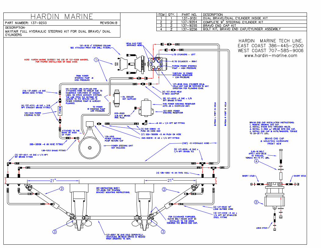
2. Before making up hoses please reference Hose End Assembly Instructions. For appropriate plumbing diagrams, please reference the following: Full Hydraulic, Single Bravo/Single Cylinder (assembly print drawing 137-9201) Full Hydraulic, Single Bravo/Dual Cylinder (assembly print drawing 137-9202) Full Hydraulic, Dual Bravo/Dual Cylinder (assembly print drawing 137-9203) Space Saver Full Hydraulic, Single Bravo/Single Cylinder (assembly print 137-9510) Space Saver Full Hydraulic, Single Bravo/Dual Cylinders (assembly print 137-9511) Space Saver Full Hydraulic, Dual Bravo/Dual Cylinders (assembly print 137-9512) Hardin Marine suggests the use of part #137-9309 Mandrel for proper installation of hose end.
3. Remote mount reservoir installation Before installing the remote mount power steering reservoir the stock fill cap on the power steering pump must be removed and replaced with the power steering return dump cap provided. Simply tighten the center screw on the new cap snugly to prevent leaks. The remote reservoir tank must be mounted as close as possible to the power steering pump keeping the bottom of the tank above the top of the pump. The hose must run slightly uphill from the pump to the reservoir to insure proper purging of air.
4. High-pressure filter and pressure line installation The power steering filter is a high-pressure filter and must be plumbed in-line on the high-pressure output hose between the power steering pump and the P port on the steering helm. It is very important to mount the filter in the direction of flow meaning IN from the pump and OUT to the helm. If not installed properly the internal element will fail and block the flow of the entire system. All -6 male adapters and -6 hose ends are provided to completely install the power steering filter.
5. Return line routing The T port on your helm is the “tank” or reservoir low-pressure return line. This hose returns the low-pressure fluid back to the reservoir on the power steering pump. This
11 Industry Drive Palm Coast, FL 32137
Phone 877.900.7278 Fax 386.445.1122
hose must run through an in line power steering cooler before reaching the power steering reservoir tank.
6. Directional line routing The L or left port on the helm and the R or right port on your helm are the lines that run back and connect to your steering cylinders. A revue of the plumbing diagram provided will instruct you on the proper routing on the left and right steering hoses.
General All hydraulic hoses should be washed completely and blown out with compressed air before installing. Connect hoses to the hydraulic components according to the plumbing diagrams provided. Refer to STEP 2 for appropriate plumbing diagram.
BRAVO END CAP & ATTACHMENT HARDWARE 1. Stock Bravo end cap removal
Remove the three retaining bolts attaching the stock upper rear cap to the back of the upper gear housing. It may be necessary to loosen the top cap bolts to achieve this. A certain amount of oil loss may occur during this process. Be sure to pay special attention to the neutral detent spring and plunger that must be placed into the new steering end cap upon installation.
2. Steering cap stud installation Studs are provided to replace the three stock rear cap attachment bolts previously used. The two shorter studs are to be installed on the two top holes while the longer one is intended for the center bottom hole. Upon installation, apply red Loctite to the threads before installing the three new studs.
3. Steering end cap installation Upon installation of the new stainless steel steering end cap assembly it is important that the spring and neutral detent plunger from the old end cap is installed properly. Use a multi-purpose lubricant on the new o-ring/gasket and place the end cap over the newly installed studs. Once properly seated, using the nuts and washers provided, evenly torque the end cap to 30-35 ft. lbs.
General Once the new end cap is installed, re-torque the top cap if it was loosened upon installation 30-35 ft. lbs. Very Important to check sterndrive oil level before operation!
STERNDRIVE WING PLATE
1. Installation of the Space saver stern drive rear steering mount plate requires initial removal of the stern drives from the gimbal housing. Removal of the (6) 7/16”outdrive retaining nuts will allow the out drive to be pulled away from the gimbal housing. Gently slide the stern drive away from the gimbal housing a few inches to expose the forward / reverse shift cable and connector. Spread the jaws of the connector apart to release the stern drive from the cable.
2. Next, remove the top four (4) out drive mounting studs. The two (2) upper studs on each side must be removed and replaced with the new four (4) extended length-mounting studs provided with your steering system. Use Loctite (RED) thread sealer (sold separately) upon re-installation of the new extended length mounting studs
11 Industry Drive Palm Coast, FL 32137
Phone 877.900.7278 Fax 386.445.1122
3. After installation of the new extended length mounting studs has been completed re-
install the stern drive onto the four (4) new and two (2) existing mounting studs now the stainless steel washers and nuts can be re-installed on the lower original mounting studs to hold the stern drive secure while installing the Space Saver wing plate. Next install the Mayfair stern drive cylinder mounting wing plate onto the four (4) upper extended length studs that you just installed. The wing plate should have the cylinder mounting bolt heads facing up with the locking nuts on the bottom side of the wing plate assembly. Lastly install the stainless steel flat washers onto the six (6) mounting studs as well as the appropriate nylon lock style nuts and torque all of the nuts to O.E.M specifications
STERNDRIVE STEERING CYLINDERS with WING PLATE or END
CAP
1. Attaching the clevis to steering end cap or wing plate Install steering cylinders to the Space Saver wing plate with proper provided mounting fasteners. Extend steering cylinder to ½ of the cylinders allowable stroke so that the hydraulic inlet/outlet ports are facing upward and so that the transom mounting bracket is horizontal to the transom assembly. Position the stern drive gear housing so that it is straight ahead, fore and, aft and trim the out drive to its normal operating position. This can be achieved by positioning or aligning the propeller shaft parallel to the bottom of the boat.
2. Drilling transom for bracket Next hold the steering cylinder mounting bracket against the transom of the boat maintaining a horizontal parallel mounting plane to the crankshaft centerline. At this point use the transom mounting plate and drilling template to identify and mark the location of the mounting holes that will be drilled in the next step. Refer to the drilling template for approximate distances in inches. It may be helpful to use masking tape to reference the transom mounting plate location. A certain amount of variance is tolerated when necessary. Steering cylinder mounting flange area on the transom must flat, level, and solid. Always confirm that this area is free of any internal deterioration or dry rot. Next check the inside of the transom to make sure the area is free of any obstructions and proceed to drill the appropriate mounting holes. The steering cylinder transom mounting bracket can be used as the template when drilling 3/8” mounting holes. Make sure and use a proper sealing material (3M 5200 sealant) when fastening the steering cylinder to the transom.
BLEEDING AIR FROM POWER STEERING SYSTEM
Before filling the system with fluid check all hose connections for tightness and proper routing according to the plumbing diagrams referenced below: Full Hydraulic, Single Bravo/Single Cylinder (assembly print drawing 137-9201) Full Hydraulic, Single Bravo/Dual Cylinder (assembly print drawing 137-9202)
11 Industry Drive Palm Coast, FL 32137
Phone 877.900.7278 Fax 386.445.1122
Full Hydraulic, Dual Bravo/Dual Cylinder (assembly print drawing 137-9203) Fill reservoir tank 3/4 full with GM high performance power steering fluid or Valvoline synthetic power steering fluid. IMPORTANT: Keep reservoir tank at least half full during the bleeding process to prevent air being reintroduced into the system. The engine containing the power steering pump must be run to properly bleed the system. Check all hose and fitting connections for any leaks while running the engine at an idle. Keep the reservoir tank 1/2 full at all times during the bleeding process. Begin to cycle the steering wheel slowly from side to side until you start to feel a hard lock out. Repeat this process until a deliberate stop occurs in both directions. To check if the system is bled properly, align the sterndrive in the straight-ahead position and turn the engine off. Go behind the boat and manually try to move the sterndrive back and forth. If the cylinder rods move in and out, there is still air in the system. If a “slight” amount of air remains in the system this should be eliminated after the boat is run.