hardware and software manual - scanivalvescanivalve.com/media/28009/dts4050_v109.pdfhardware and...
TRANSCRIPT

DTS4050/16TxDTS4050/32TxDTS4050/64Tx
Thermocouple Scanners
Hardware and Software ManualSoftware Version 1.09

iv
DTS4050Section 1: Introduction iv
DTS4050Preface
PREFACEWarnings, Cautions and Notes
The WARNING! symbol indicates that danger of injury for persons and the environment and/or considerable damage (mortal danger, danger of injury) will occur if the respective safety precau-tions are not taken.
The CAUTION ! symbol indicate danger for the system and material if the respective safety precau-tions are not taken.
The ESD note symbol indicates that proper precautions for handling Electrostatic Sensitive Devices needs to be taken when performing the related operation. This includes the use of grounded work surfaces and personal wrist straps to prevent damage to sensitive electronic components.
Warranty Scanivalve Corporation, Liberty Lake, Washing-ton, hereafter referred to as Seller, warrants to the Buyer and the first end user that its products will be free from defects in workmanship and materi al for a period of twelve (12) months from date of delivery. Written notice of any claimed defect must be received by Seller within thirty (30) days after such defect is first discovered. The claimed defective product must be returned by prepaid transporta-tion to Seller within ninety (90) days after the defect is first discovered. Seller’s obligations under this Warranty are limited to repairing or replacing, at its option, any product or component part there of that is proven to be other than as herein warranted.
Surface transportation charges covering any repaired or replace ment product or component part shall be at Seller’s expense; however, inspection, testing and return transportation charges covering any product or com-ponent part returned and redelivered, which proves
not to be defective, shall be at the expense of Buyer or the end user, whichever has returned such product or compo-nent part.
This Warranty does not extend to any Seller product or component part thereof which has been subjected to misuse, accident or improper installation, maintenance or application; or to any product or component part thereof which has been repaired or altered outside of Seller’s facili-ties unless authorized in writi ng by Seller, or unless such installation, repair or alteration is performed by Seller; or to any labor charges whatsoever, whether for removal and/or reinstallation of the defective pro duct or component part or otherwise, except for Seller’s labor charges for repair or replacement in accordance with the Warran ty. Any repaired or replacement product or component part there of provided by Seller under this Warranty shall, upon redelivery to Buyer, be warranted for the unexpired portion of the original product warranty.
THIS WARRANTY IS IN LIEU OF AND EXCLUDES ALL OTHER WARRANTIES, EXPRESS OR IMPLIED, ARISING BY

v
DTS4050 Section 1: Introduction
v
DTS4050 Preface
OPERATION OF LAW OR OTHERWISE, INCLUDING THE IMPLIED WARRANTIES OF MERCHANTABILITY AND FITNESS FOR A PARTICULAR PURPOSE, AND IN NO EVENT SHALL SELLER BE LIABLE FOR INCIDENTAL OR CONSEQUENTIAL DAMAGES. In the event of a failure: 1) Notify Scanivalve Corporation, Customer Service De partment. Include model number and serial number. On receipt of this information, service data or shipping instructions will be forwarded. This may be transacted by telephone or e-mail. 2) On receipt of shipping instructions, forward the pro duct, transportation prepaid. Repairs will be made and the product returned. 3) All shipments should be made via “Best Way”. The product should be shipped in the original packing con-tainer or wrapped in protective material and surrounded by a minimum of four (4) inches of a shock absorbing material.
Trademarks ® and Copyrights ©Scanivalve is a registered trademark of Scanivalve Corpora-tion.
All other brand and product names are trademarks or regis-tered trademarks of their respective companies.
Packaging for ShipmentIf the product must be shipped, whether being returned to Scanivalve or relocated to another location it must be packaged properly to minimize the risk of damage. The recommended method of packing is to place the instru-ment in a container, surrounded on all sides with at lease four inches of shock attenuating material such as Styrofoam peanuts.
Important NoticePlease note that the product specifications and other information contained in this manual are subject to change without notice. Scanivalve Corporation makes an effort and strives to provide complete and current information for the proper use of the equipment. If there are any questions regarding this manual or the proper use of the equipment, contact Scanivalve Corporation.
Contact InformationIf there are any questions or concerns regarding any Sca-nivalve product please do not hesitate to contact us at the following:
Scanivalve Corp.1722 N. Madson StreetLiberty Lake, WA 99019
Telephone: (800)935-5151 (509)891-9970Fax: (509)891-9481
Scanivalve Corporation is an ISO9001:2000 certified com-pany.

[This page intentionally left blank]
1
DTS4050 Table of Contents
TABLE OF CONTENTSPREFACE iv
Warnings, Cautions and Notes ivWarranty ivTrademarks ® and Copyrights © vPackaging for Shipment vImportant Notice vContact Information v
Section 1: Specifications 7General Specifications 7Environment Specifications 7DTS4050/16Tx - Screw Terminal Outline Drawing 8DTS4050/16Tx - Panel Jack Outline Drawing 9DTS4050/32Tx - Screw Terminal Outline Drawing 10DTS4050/32Tx - Panel Jack Outline Drawing 11DTS4050/64Tx Outline Drawing 12
Section 2: Introduction 13General Description 13Module Configurations 13
Screw Terminal 13Panel Mount Version 13Heater Option 13
Environmental Considerations 13
Section 3: Operation 15Unpack & Inventory 15Mounting 15Warm-up 15Communications 15
Serial Communications 15Ethernet Communications 16
Client/Host Options 16PC - TCP/IP 16PC - UDP 17PC - ScanTel 17PC - LabVIEW Configuration Utility 17PC - LabVIEW Development Kit 17PC - OPC Server 17PC - HyperTerminal 17
Scanning 17Scanning With An External Trigger 18
Hardware Trigger 18Software Trigger 18

2
DTS4050Table of Contents
DIP Switch Settings 18DSP Boot Loader 18
FTP 18Boot Loader and Application File System 19Host Communication 19Commands 19
IEEE-1588 PTP 20
Section 4: Hardware 21Electrical Connections 21
Ethernet Connection 21Trigger/Config Connection 21Power Connection 21
Thermocouple Inputs 22Screw Terminal Connections 22Panel Jack Connections 22
Insulation Cover (Screw Terminal) 22Thermocouple Grounding Scenarios 23
Section 5: Software 25DTS Control and Configuration 25
TCP Telnet Server 25UDP ID Server 25Serial Commands 25Data Transfer 25
DTS 4050 Command and Data Output Matrix 26Command List 27
A/D Calibration 27Auto Status 27Bootloader Version 28CLEAR 28Close Host Binary Server Connection 28Connect to Host Binary Server 29Correct RTD Voltage Tables 29Enter Channel Calibration Setpoints 30Enter RTD Calibration Setpoints 30Error 31Fill 31Get PTP Time 31Get UTC Offset 32Host Binary Server Command 32Ice Point Offset Adjustment 32List Bootloader Group Variables 33List Calibration 33List Channel Correction Setpoints 34List Channel Correction Setpoints (multi-temperature calibration) 35List Channel Definitions 35List Configuration Variables 35List Files 36List Gain 36List Identification 37

3
DTS4050 Table of Contents
List Labels 37List Limits 38List Network Identification 38List Offset 39List Precision Time Protocol 39List RTD Correction Values 40List RTD Conversion Values 40List RTD Current Conversion Values 41List Scan Variables 41List UTR Calibration Variables 42Open Thermocouple Test 42Clear Accumulated PTP Data 42Display PTP Statistics 43Reboot 43Save 43Save Bootloader Variables 44Save PTP Variables 44Scan 45Scan Trigger 47Set 47Status 48Stop 48Version 48
Configuration Variables 49Scan Variables (LIST S) 49
Average (AVG) 49BINARY (BIN) 49Format (Format) 49Frames Per Scan (FPS) 50Period (Period) 50QPKTS (QPKTS) 50Temperature Range Over Range Values (RANGET) 50Voltage Range Over Range Values (RANGEV) 51Scan Rate (RATE) 51Units (UNITS) 52Scan Trigger (XSCANTRIG) 52
Channel Correction Variables (LIST P) 53PT (PT) 53PT <type> (PT <type>) 54
Identification Variables (LIST I) 55Auto Connect (AUTOCON) 55Echo (ECHO) 55Host (HOST) 55Host Command (HOSTCMD) 55Port (PORT) 56RTD Maximum Slew Limit (RTDMAXSLEW) 56Thermocouple Maximum Slew Limit (TCMAXSLEW) 56Title 1 (TITLE1) 56Title 2 (TITLE2) 56
Bootloader Variables (LIST IP) 57DTS4050 IP Address (IPADD) 57DTS4050 Subnet Mast (SUBNET) 57DTS4050 MAC Address (MAC) 57

4
DTS4050Table of ContentsLogin (LOGIN) 57Password (PASSWORD) 58Login 1 (LOGIN1) 58Password 1 (PASSWORD1) 58Allow Anonymous Logon (ALLOWANON) 58Application File (APP) 58Gateway (GW) 59
Calibration Variables (LIST C) 59A/D Calibration Averaging (CALAVG) 59Number of Calibration Setpoints (NUMPTS) 59Number of Calibration Coefficients (NUMCOEF) 59Number of Calibration Temperatures (NUMTEMPS) 60
Precision Time Protocol Variables (LIST PTP) 61PTP Enable (PTPEN) 61Tune (TUNE) 61Syslog Severity Level (SLL) 61Statistical Data Destination (STAT) 62Start Scan Time (SST) 62Start Scan Date (SSD) 62Update Clock (UC) 63Interval (INTERVAL) 63Clock Drift Adjustment (ADJDRIFT) 63UTC Offset (UTCOFFSET) 63
Network Identification Variables (LIST ID) 64Model (MODEL) 64Serial Number (SERNUM) 64Version (VER) 64IP Address (IPADD) 64
Channel Identification Variables (LIST DEF) 65Channel Definitions (DEF) 65
Limit Variables (LIST LI) 65Limit (LIMIT) 65
Channel Labels (LIST LA) 65Channel Label (LABEL) 65
Thermocouple Variables (LIST T) 66Thermocouple Type (TYPE) 66
RTD Correction Variables (LIST RPC) 67RTD Correction (RPC) 67
RTD Conversion Volts to Ohms (LIST RTD) 68RTD 1 (RTD 1) 68RTD 2 (RTD 2) 68RTD 3 (RTD 3) 68RTD 4 (RTD 4) 68RTD 5 (RTD 5) 69RTD 6 (RTD 6) 69RTD 7 (RTD 7) 69RTD 8 (RTD 8) 69
Channel Gain Correction Variables (LIST G) 70Gains (GAIN) 70
Channel Offset Correction Variables (LIST O) 70Offsets (OFFSET) 70
RTD Calibration Variables (LIST U) 71
5
DTS4050 Table of Contents
ARPC (ARCPC) 71ARPCON (ARPCON) 71Maximum RTD Delta (MAXDELTA) 71Number of RTD Setpoints (RNUMPTS) 71Number of RTD Coefficients (RNUMCOEF) 72
DTS Packet Definitions 73Packet Type Table 73
Host Control Packets 73Command Packet 73
DTS to HOST 74Binary Data Packets (DTS4050/16 Channel Module) 74Binary Data Packets (DTS4050/32 Channel Module 75Binary Data Packets (DTS4050/64 Channel Module) 76
General Status Byte 77General Status Byte 77
Channel Status Byte 78Channel Status Byte 78RTD Units 78
ASCII Data Packet 79Unformatted Without PTP Data 80Unformatted With PTP Data 80Formatted 81
Network Protocols Supported 81
Section 6: Maintenance 83Calibration 83A/D Calibration (ADCAL) 83Internet Explorer Setup for FTP 83DTS4050 Firmware Installation (Windows XP & 7) 84Operating in Bootloader Mode 85Reformatting the DTS4050 86
Appendix 87Appendix A: Thermocouple Information 87
Thermocouple Basics 87Sources of Error in Thermocouple Measurements 88Noise in Thermocouple Circuits 88Thermocouple Design 88Thermocouple Types and Descriptions 89International Thermocouple and Extension Wire Color Codes 90
Appendix B - Software Change List 91

6
DTS4050Section 1: Specifications
[This page intentionally left blank]
7
DTS4050 Section 1: Introduction Section 1: SpecificationsDTS4050
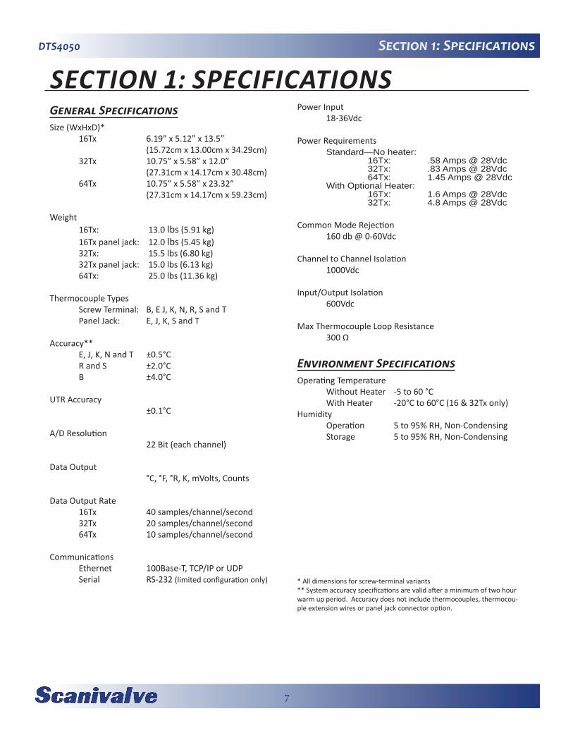
SECTION 1: SPECIFICATIONSGeneral SpecificationsSize (WxHxD)* 16Tx 6.19” x 5.12” x 13.5” (15.72cm x 13.00cm x 34.29cm) 32Tx 10.75” x 5.58” x 12.0” (27.31cm x 14.17cm x 30.48cm) 64Tx 10.75” x 5.58” x 23.32” (27.31cm x 14.17cm x 59.23cm)
Weight 16Tx: 13.0 lbs (5.91 kg) 16Tx panel jack: 12.0 lbs (5.45 kg) 32Tx: 15.5 lbs (6.80 kg) 32Tx panel jack: 15.0 lbs (6.13 kg) 64Tx: 25.0 lbs (11.36 kg)
Thermocouple Types Screw Terminal: B, E J, K, N, R, S and T Panel Jack: E, J, K, S and T
Accuracy** E, J, K, N and T ±0.5°C R and S ±2.0°C B ±4.0°C
UTR Accuracy ±0.1°C
A/D Resolution 22 Bit (each channel)
Data Output °C, °F, °R, K, mVolts, Counts
Data Output Rate 16Tx 40 samples/channel/second 32Tx 20 samples/channel/second 64Tx 10 samples/channel/second
Communications Ethernet 100Base-T, TCP/IP or UDP Serial RS-232 (limited configuration only)
Power Input 18-36Vdc
Power Requirements Standard—No heater: 16Tx: .58 Amps @ 28Vdc 32Tx: .83 Amps @ 28Vdc 64Tx: 1.45 Amps @ 28Vdc With Optional Heater: 16Tx: 1.6 Amps @ 28Vdc 32Tx: 4.8 Amps @ 28Vdc Common Mode Rejection 160 db @ 0-60Vdc
Channel to Channel Isolation 1000Vdc
Input/Output Isolation 600Vdc
Max Thermocouple Loop Resistance 300 Ω
Environment SpecificationsOperating Temperature Without Heater -5 to 60 °C With Heater -20°C to 60°C (16 & 32Tx only)Humidity Operation 5 to 95% RH, Non-Condensing Storage 5 to 95% RH, Non-Condensing
* All dimensions for screw-terminal variants** System accuracy specifications are valid after a minimum of two hour warm up period. Accuracy does not include thermocouples, thermocou-ple extension wires or panel jack connector option.

8
DTS4050Section 1: Specifications
DTS4050/16Tx - Screw Terminal Outline Drawing
Figure 1.1 - Physical Specification, DTS4050/16Tx, screw term
inal inputs

9
DTS4050 Section 1: Introduction Section 1: SpecificationsDTS4050
DTS4050/16Tx - Panel Jack Outline Drawing
Figu
re 1
.2 -
Phys
ical
Spe
cifi
cati
on, D
TS40
50/1
6Tx,
pan
el ja
ck in
puts

10
DTS4050Section 1: Specifications
DTS4050/32Tx - Screw Terminal Outline Drawing
Figure 1.3 - Physical Specification, DTS4050/32Tx, screw term
inal inputs

11
DTS4050 Section 1: Introduction Section 1: SpecificationsDTS4050
DTS4050/32Tx - Panel Jack Outline Drawing
Figu
re 1
.4 -
Phys
ical
Spe
cifi
cati
on, D
TS40
50/3
2Tx,
pan
el ja
ck in
puts
12
DTS4050Section 1: Specifications
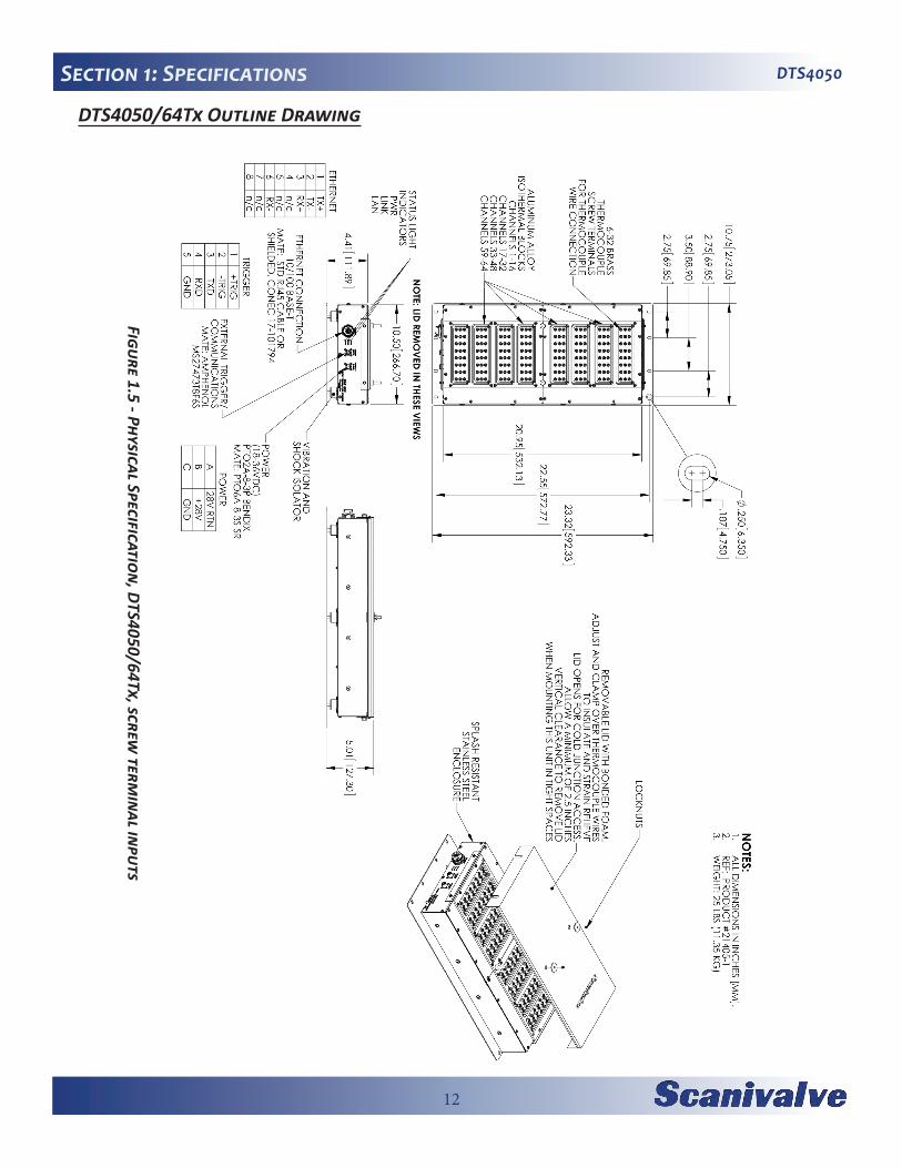
DTS4050/64Tx Outline Drawing
Figure 1.5 - Physical Specification, DTS4050/64Tx, screw term
inal inputs

13
DTS4050 Section 2: Introduction
SECTION 2: INTRODUCTIONGeneral DescriptionThe DTS4050 series thermocouple acquisition system represents the next generation of intelligent temperature scanning. This Digital Temperature Scanner incorporates 16, 32 or 64 pair of thermocouple inputs, a 22 bit A/D converter for each input channel, RAM and a DSP proces-sor. The DTS in packaged in a in a rugged, shock mounted, stainless steel enclosure.
An Isothermal block is incorporated for the Uniform Tem-perature Reference (UTR), with a ± 0.1°C accuracy. The temperature of each UTR block is measured using two PT100 RTDs. A single UTR block can act as the reference for 16 thermocouple inputs. NIST thermocouple tables for standard thermocouple types are stored in Flash Memory. The DSP processor uses these look-up tables to convert mV inputs to Engineering units. Temperature data may be output in °C, °F, °R, K, mVolts, Counts. The DTS4050 total system error does not include extension wire and external connectors, or panel jacks.
Multiple standard thermocouple types may be used with this intelligent thermocouple scanner. The DTS4050 can accept grounded and un-grounded thermocouples.
Module ConfigurationsThe DTS4050 is available in 16, 32 or 64 input versions. Several optional configurations are available in order to meet the requirements of specific tests.
Screw TerminalThis is the standard configuration for all DTS4050 modules. Thermocouples are terminated at the DTS4050 with #6x32 brass screws into the UTR block. DTS4050 modules are available in versions that will accept 16, 32 or 64 shielded thermocouples. The top cover and insulation isolate the UTR from small temperature changes giving this unit the best accuracy.
Panel Jack VersionDTS4050 modules may have panel jacks installed as an option in 16Tx and 32Tx version. This option uses either Omega TPJ series or UPJ series panel jack receptacles and is available for type E, J, K, S and T thermocouples only. This option reduces the overall accuracy of the module by a factor of two. This error may be calibrated out by the user using the Gain and Offset terms. Unused panel jacks must be plugged to prevent “cold spots” on the UTR which will cause errors.
Panel Mount VersionDTS 4050/64Tx modules may be ordered in either the standard shock mount configuration or in an optional Panel mount configuration. The Panel Mount configuration is designed to be mounted in a standard 19 inch rack mount cabinet. The mounting ears may be reversed to facilitate the most convenient mounting configuration
Heater Option16 and 32 channel DTS4050 modules can be equipped with an internal heater for cold environment applications. The heater kit option increases the DTS4050’s operational ambient temperature range to -20°C to 60°C by maintaining the internal temperature of the module at approximately +20°C. With a heater installed, the power requirements for the DSTS4050 module increase to:
DTS4050/16Tx: 1.6A @ 28VdcDTS4050/32Tx: 4.8A @ 28Vdc
The standard nominal power range of 18-36Vdc still applies. The power consumption of the module will decrease once the temperature of the module has stabi-lized.
Environmental ConsiderationsDTS4050 modules are constructed with a rugged, corro-sion resistant stainless steel case. This case is designed with withstand normal test cell, flight test, educational, light industrial or similar environments. The case is splash resistant but not water proof. If any moisture gets spilled or splashed on the DTS module, wipe it dry immediately to prevent damage to the module. The DTS module should not be mounted outdoors.
The DTS module is designed for rugged applications and incorporates shock mounts for vibration isolation and Bendix/Amphenol connectors for power and serial inputs as well as a Conec connector with optional protective shell for the Ethernet connection.
The DTS module should not be mounted in a location where it may be subjected to extreme temperature shifts or ambient temperatures outside of the specified operat-ing range of the module. Pay careful attention to prevent any temperature “gradients” across the module as the UTR blocks must be at a completely consistent temperature. Keep in mind that the internal temperature of the module will run several degrees warmer than ambient tempera-ture.

14
DTS4050Section 3: Installation & Operation
[This page intentionally left blank]

15
DTS4050 Section 3: Installation & Operation
SECTION 3: OPERATIONUnpack & InventoryWhen you first unpack the DTS module, begin by inspect-ing and inventorying the contents of the package. If any visible damage is immediately noticed or if any contents are missing, contact Scanivalve before proceeding. Stan-dard modules are shipped with the following contents as a minimum:
1. DTS4050 module2. Certificate of calibration3. Full calibration report CD4. DTS resource CD5. Trigger/configuration cable connector6. Power cable connector7. Ethernet cable connector
MountingThe DTS module comes with a mounting plate attached to the bottom using vibration dampers. This mounting plate accepts mounting hardware up to 1/4” (6.4mm) in diame-ter. The DTS module can be mounted in most orientations. Because the DTS Uniform Temperature Reference block (UTR) has two RTDs to measure the temperature, the DTS should NOT be mounted in an orientation that puts these RTDs vertical to each other. Mounting the DTS such that the RTDs are vertical to each other produces a temperature gradient across the UTR block that cannot be accurately represented by the two RTD readings. This is only a con-cern if the DTS is mounted “vertically,” such as on a wall. If the DTS does need to be mounted vertically, then 16 chan-nel units must be mounted with the connectors horizontal (left or right). 32 and 64 channel units must be mounted with the connectors vertical, on the top or bottom face. Additionally, ensure that the DTS module is mounted in an environment that conforms to the requirements described in “Environmental Considerations” on page 13.
A minimum clearance of 6.25” must be left above 16Tx module and 1.5” above 32Tx & 64Tx module in order to open or remove the insulating cover.
CAUTION! Mounting the DTS module inadequately or in an environment that does not conform to the recom-mendations can results in permanent damage to the module.
Warm-upAfter applying power to the DTS module, a minimum of two hours is required to allow the module temperature to become stable before collecting data. It is recommended
that if time allows, the warm-up period should be extended to three hours for most applications.
CommunicationsThe DTS module is designed primarily for Ethernet com-munications. This provides a means to configure the DTS module as well as scan and collect data from the module. A serial RS-232 port is also provided. The serial connection is designed to provide emergency communications should Ethernet communications not be available. Several impor-tant module variables can be configured through the serial port, but possibly the most important is the Ethernet IP address. If the IP address of the unit has been lost, a Serial connection is the only way to reset the IP address. See “Operating in Bootloader Mode” on page 85 for step by step instructions on entering the bootloader and change the module’s IP address.
Serial CommunicationsEvery DTS4050 module has an RS-232 serial output. It is available through the ‘Serial Communications/Trigger’ connector on the front face of the module. The bulkhead connector for the ‘Serial Communications/Trigger” connec-tion on the module is an Amphenol JTP02RE8-6P. All DTS modules are shipped with a mating connector (Amphe-nol JTO1RE8-6SR) that can be used to fabricate a Serial Communications/Trigger cable. Alternately, a Serial Com-munication/Trigger cable can be ordered from Scanivalve using the Scanivalve part number 155829.
The wiring diagram for the RS-232 output is shown below. The cable wiring must connect the Tx output from the host computer to the Rx input of the DTS module. Also, the RX input of the host computer must connect to the Tx output of the DTS module.
Figure 3.1 - Serial Communication/Trigger Cable

16
DTS4050Section 3: Installation & OperationSettings for establishing a serial connection to the DTS module are as follows:
Bits per second: 9600 BAUDData bits: 8Parity: noneStop bits: 1Flow control: none
The Serial Communications port also serves as the input for the external scan trigger. For more information on exter-nally triggering scans, “Scanning With An External Trigger” on page 18.
For information on changing the boot parameters including the module’s Ethernet IP address, see “Operating in Boot-loader Mode” on page 85.
Ethernet CommunicationsA DTS4050 has one Ethernet connection, 10/100Base-T with MDIX auto-crossing. This is the primary means of communications with the DTS. All DTS modules use a Conec RJ45-IP67 series connector for the Ethernet con-nection. This connector offers the ability to use a standard RJ-45 Ethernet cable or, when needed the shield can be installed for a more rugged connection. Shielded Category 5E cable or better is recommended for all Ethernet connec-tions.
Figure 3.2 - 10Base-T Ethernet CablesBefore an Ethernet connection can be established the IP address need to be configured. In order to be compatible, the IP address of the module and host computer must share the first two octets. The third and fourth octets of the IP address is variable, although it is recommended that the third octet also be shared between the host computer and the module.
Example of matching the first three octets (recommended): Host computer: 191.30.80.100 DTS module: 191.30.80.125Example of matching the first two octets: Host computer: 191.30.1.100 DTS module: 191.30.80.125
The IP address of a Windows XP host computer can be changed under:
Control Panel -> Network Connections -> Local Area Network -> Properties -> Internet Protocol (TCP/IP) -> Properties.
The IP address of a Windows 7 host computer can be changed under:
Control Panel -> Network and Sharing Center -> Local Area Connection -> Properties -> Internet Protocol Ver-sion 4 (TCP/IPv4) -> Properties.
DTS modules are shipped with a preset IP address that uses the following format:
DTS4050/16Tx: 191.30.100.xxxDTS4050/32Tx: 191.30.105.XXXDTS4050/64Tx: 191.30.110.XXX
Where “XXX” is the last three digits of the unit’s serial number.
For information on changing the DTS module’s IP address, see “Operating in Bootloader Mode” on page 85.
Client/Host OptionsOnce the module has been connected and the IP address has been configured, communications can be established with the DTS module. Communications can be made through several software packages including:
• PC - TCP/IP• PC - UDP• PC - ScanTel (Scanivalve PN: 155406-01)• PC - LabVIEW Configuration Utility (Scanivalve PN:
155384-01)• PC - LabVIEW Development Kit (Scanivalve PN:
155385-01)• PC - OPC Server (Kepware PN: EX5-SCNVE-NA00)• PC - Windows HyperTerminal
PC - TCP/IPThe user may write their own TCP/IP interface using the software specification portion of this manual. This inter-face should allow the user to:
• Issue commands to any or all DTS modules on the network.
• Display returned information or scan data from the DTS module(s).
• Write returned information or scan data to the client/host in TCP/IP format.
• Determine the addresses of DTS module(s) on the network.

17
DTS4050 Section 3: Installation & Operation
PC - UDPThe user may write their own UDP interface using the soft-ware specification portion of this manual. This interface should allow the user to:
• Issue commands to any or all DTS modules on the network.
• Display returned information or scan data from the DTS module(s).
• Write returned information or scan data to the client/host in UPD format (no handshaking).
• Determine the addresses of DTS module(s) on the network.
PC - ScanTelScanTel a free communications utility designed by Scani-valve to communicate with Scanivalve products including DTS modules. It is a text based, command line program that allows users to connect to a single DTS module and modify the configuration variables, upload or download coefficients and collect data in both TCP/IP and UDP format.
PC - LabVIEW Configuration UtilityThe Scanivalve LabVIEW Configuration Utility is software package that offers a very intuitive and simple way to con-nect to and modify all of the DTS module’s configuration variables. It also allows the user the ability to upload a configuration file and scan and collect data. The scanning and data collection is limited to 5Hz due to the graphic nature of the program. The LabVIEW Configuration Utility is based on a LabVIEW 2009 runtime which is included with the installation disk.
PC - LabVIEW Development KitThe Scanivalve LabVIEW Development Kit is for users desir-ing to customize a LabVIEW driver for DTS modules. The Development Kit is compatible with LabVIEW 8.2, 8.6 and 2009. The LabVIEW Configuration Utility is included with the Development Kit.
PC - OPC ServerKepware has written an OPC Server driver to interface a PC running in an OPC environment with a 16 channel DTS module. The OPC server can be ordered directly from Kepware using the part number: EX5-SCNVE-NA00. This program is designed to operate in Windows 2000 or Win-dows XP.
PC - HyperTerminalHyperTerminal is a Windows program included as part of Windows 2000, XP and Vista Operating Systems. This program permits a user to connect to a single DTS module, modify the configuration variables, upload or download coefficients and collect data. HyperTerminal provides a means for both Serial RS-232 and Ethernet connections. It is a text based command line program.
ScanningOnce the DTS module has been installed, powered up and allowed to thermally stabilize data can be collected. There are several configuration variables that effect how the DTS module scans and how the data is output. The scan rate is controlled by two variables: ‘period’ and ‘average’. Alter-nately, these two variables can be set automatically using the ‘rate’ variable. The length of the scan sample is deter-mined by the ‘frames per scan’ (FPS) variable and the data output format is determined by the ‘format’ variable. The DTS can be configured for ‘free run’ mode where after the ‘SCAN’ command is send the DTS module will scan continu-ously until the frames per scan (FPS) term is met, or it can be triggered to scan and output data upon receipt of a scan trigger (either external or a software trigger). The following is a brief list of common commands that effect how the DTS collects data.
AVG BIN CVTUNIT EU FORMAT FPS
RATE PERIOD TIME UNITS XSCANTRIG TYPE
More information on all of these configuration variables can be found in “Section 5: Software” on page 25.
To initiate scanning, simply send the command: ‘SCAN’. If a scan trigger is not being used, data will begin to be output from the DTS module over the Ethernet connection. This data can be collected and recorded using one of the options described in “Client/Host Options” on page 16. If a scan trigger is being used, after the ‘SCAN’ command is sent one frame of data will be output each time a scan trigger is received.

18
DTS4050Section 3: Installation & Operation
Scanning With An External TriggerThe DTS module can be triggered to scan with either a hardware or a software trigger. The DTS also incorporates a “trigger divider.” This function allows the unit to be paced at a rate slower than the input trigger rate. More infor-mation on the trigger input divider can be found in “Scan Trigger (XSCANTRIG)” on page 52.
Hardware TriggerThe external trigger input is optically isolated to prevent grounding problems. It is a TTL level, edge sensing device. It requires a minimum signal of 4.5 Vdc @ 6.5 mA. It may accept voltages as high as 15 Vdc. The external trigger will only be active if the XSCANTRIG variable is set to 1 or greater. When a ‘SCAN’ command is issued through the Ethernet connection, the module enters the scan mode and waits for a trigger. The module will return an averaged frame of data for each trigger pulse received. This will con-tinue until the Frames Per Scan (FPS) term is met or until a ‘STOP’ command is issued. Trigger pulses are received through pins 1 (+Trig) and 2 (-Trig) of the ‘Serial Communi-cations/Trigger’ connector on the front of the DTS module. More information on the ‘Serial Communications/Trigger’ connection can be found in “Serial Communications” on page 15.
Figure 3.5 - Trigger wiring
Software TriggerThe software trigger will only be active if the software variable XSCANTRIG is set to 1 or greater. When a SCAN command is issued through the Ethernet connection, the module will enter the SCAN mode and wait for a trigger. An averaged frame of data will be output as soon as the TRIG command or a <TAB> character (9 HEX or Control I) is received. Data will be output with each successive trigger command. This will continue until the Frames Per Scan (FPS) variable value is met, or until a STOP command is issued.
DIP Switch SettingsThe processor board has 4 DIP switches that affect the operation of the software. These switches are only read at power up. Changes to the dip switches are not effective until the power is cycled.
SW1 - When this switch is off, the application automati-cally boots on power up. When this switch is on, the DTS4050 remains in the bootloader mode. Default is on.
SW2 - When this switch is off, the boot loader will run in the debug mode. Debug output is directed to the serial port. Default is on.
SW3 - This switch sets the device type for the boot-loader. Off is for a DTS, on is for a DSA.
SW4 - Spare.
“Figure 3.6 - DIP Switches” shows the DTS4050 end cover removed and the location of the DIP switches on the pro-cessor board. For all DIP switches, “on” is away from the board, towards the bottom of the DTS.
Figure 3.6 - DIP Switches
DSP Boot LoaderThe Scanivalve DSP Boot Loader permits a user to upload the DTS4050 application via FTP. The boot loader runs the FTP server. It has been tested on Mozilla ‘FileZilla’ and Win-dows Explorer drag and drop. Any additional file transfer protocols or additional FTP client support modification will be made solely to the application. For more information on bootloader operation, refer to “Operating in Bootloader Mode” on page 85. FTPThe FTP server supports the following FTP commands prior to login:
USER - Allows the user to enter the user’s name. Anony-mous is allowed if the variable ALLOWANON is set to 1.
PASS - Allows the user to enter the password.QUIT - Disconnects from the FTP server.
The FTP server supports the following FTP commands after
19
DTS4050 Section 3: Installation & Operation
login:RETR - Initiates a file transfer from the DTS to the host.STOR - Initiates a file transfer from the host to the DTS.PASV - Sets up data port so client can connect to server’s
port.LIST - Returns a directory listing of the files stored on the
DTS.SIZE - Returns the size in bytes of the file.DELE - Deletes the file.NOOP - No operation. Mostly used by the client as an
“are you still there” command.
ASCII format transfers are the only supported transfer type. Passive data connections are the only supported connec-tion type. This allows data to be transferred without the server initiating a connection to the client. This could cause firewall problems.
Boot Loader and Application File SystemFilenames are limited to the 8.3 format with no spaces allowed. Only one drive is supported. Because the DTS4050 does not have a time and date clock, all files created will have a date of Aug 8, 2008. No subdirectories are supported, however, if a file path is included in the file specification only the file name portion is used. The file will be written in the root directory of the drive. The disk drive will hold a maximum of 1024 files, or 4MB of data.
Host CommunicationCommands are issued to the DTS4050 and response is returned via either the Ethernet port or the Config port. The boot loader returns the command information to the host that it received its command. That is, when the com-mand is received from the network it is returned to the network. When it is received from the serial port, it is returned to the serial port. The SCAN function is not sup-ported in Config/Serial operation. The network supports TCP/IP connection using Telnet or HyperTerminal.
CommandsWhen a command is complete, a carriage return and line feed is returned.
The commands listed below are supported by the boot loader and the executable program, unless otherwise noted. They may be viewed and modified in the DTS4050 executable program.
VER - Returns the version of the Boot Loader. NOTE: This command is specific to the boot loader only. It should not be confused with the VER command in the application.
FDISK - Formats the Flash to all 1’s. LIST IP - Returns the settings of the IP group. This
command is explained in detail in the software manual.SET <parameter> - Set the indicated parameter.IPADD <IP address> - Sets the IP address of the DTS. If
the IPADD is changed, the power must be cycled to take effect.
SUBNET <mask> - Sets the subnet address of the DTS. If the SUBNET is changed, the power must be cycled to take effect.
MAC <MAC address> - Sets the MAC address for the DTS. If the MAC is changed, the power must be cycled to take effect.
LOGIN <user name> - Sets the user name for FTP login.PASSWORD <password> - Sets the password associated
for LOGIN.LOGIN1 <user name> - Sets the user name 1 for FTP
login.PASSWORD1 <password> - Sets the password associated
for LOGIN name1.ALLOWANON <parameter> - Sets the FTP permission to
accept anonymous connections.APP <application file name> - Sets the file name of the
application to run. This is the file name that is used when automatically running the application from the boot loader. It is also the file name used when using the RUN command. If this file is not found, an error is returned.
GW <gateway> - Sets the gateway, if used.SAVEIP - Saves the configuration variables to the work-
ing directory. When an optional file name is entered, it saves the IP group settings to that file name.
TYPE <file name> - Types the contents of the file name.LOAD <file name> - Loads the file name into the LIST IP
configuration variables.DIR - Lists the file on the FLASH chip.DEL<file name> - Deletes the file name.DIP - Reads and shows the settings of the DIP switches.
The following is returned: “DIP settings Auto Run Application 0 Debug 0 No Serial Host 0 Spare 0” where 1 indicates on, 0 indicates off. NOTE: This command is available in the boot loader only.
RUN - Runs the application named in the SET APP set-ting. NOTE: This command is available in the boot loader only.
20
DTS4050Section 3: Installation & Operation
IEEE-1588 PTPThe DTS4050 has a hardware supported slave implemen-tation of the Precision Time Protocol defined by IEEE 1588-2008, otherwise known as PTP V2. This protocol is used to synchronize the DTS4050 internal clock over the Ethernet network.
The primary function of the PTP is to accurately schedule the DTS4050 acquisition and timestamp the data it trans-mits. It can also be used to timestamp an external trigger, such as an IRIG-B pulse rate signal.
The DTS4050 may be configured to start an acquisition at a future date and time. When a SCAN command is received, the DTS4050 schedules an event for the first frame and calculates the times of the subsequent frames of data based on the RATE setting. By configuring them identically, a number of DTS4050 units may be configured to start acquiring data synchronously.
The DTS4050 may also be configured to start an acquisition at a date and time in the past. This will cause the DTS4050 to start acquiring data at the next calculated time interval specified by the start time and RATE setting. For example, if the DTS4050 is configured with a start time of 9:00:00 today, and a very slow rate of one reading per minute, it will take data at an even one minute absolute time. If a SCAN command is received at 10:00:30, it will start taking data at 10:01:00. There are practical limits to consider when using a scan start time that has passed. If the DTS4050 is configured with a start time at the beginning of the Epoch (1970/1/1 at midnight) it must calculate the time of the next frame over a very long span, resulting in significant rounding errors. The interval between readings and the accuracy of the time stamp will not be affected, but the data may not be taken at the expected absolute time. The solution is to specify a more recently passed start time.
The DTS4050 timestamps the data in either ASCII or binary data formats, when PTP is enabled. In addition, the binary packet includes the elapsed time since the last update from the grandmaster. From this, the user can detect when and if the grandmaster has gone offline. The user may enter an offset to adjust the PTP to reflect local time and/or adjust for leap seconds. The DTS4050 does not automatically adjust for leap seconds, but it does have a command to extract and display the leap second field of the PTP packets sent by the grandmaster. The format of the DTS4050 data packets can be found in “DTS Packet Definitions” on page 73.
The DTS4050 can output status information about the control loop that synchronizes the internal clock with the grandmaster. A line of data is output corresponding to each update from the grandmaster. The offset from master (OFM) is a good measure of how well the DTS4050 is synchronized with the grandmaster. For a complete explanation of the PTP status output see “List Precision Time Protocol” on page 39 and “Precision Time Protocol Variables (LIST PTP)” on page 61.
21
DTS4050 Section 4: Hardware
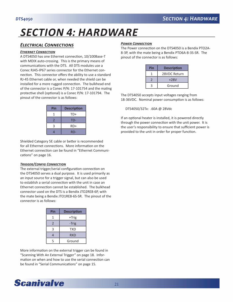
SECTION 4: HARDWAREElectrical ConnectionsEthernet ConnectionA DTS4050 has one Ethernet connection, 10/100Base-T with MDIX auto-crossing. This is the primary means of communications with the DTS. All DTS modules use a Conec RJ45-IP67 series connector for the Ethernet con-nection. This connector offers the ability to use a standard RJ-45 Ethernet cable or, when needed the shield can be installed for a more rugged connection. The bulkhead end of the connector is a Conec P/N: 17-101754 and the mating protective shell (optional) is a Conec P/N: 17-101794. The pinout of the connector is as follows:
Pin Description1 TD+2 TD-3 RD+4 RD-
Shielded Category 5E cable or better is recommended for all Ethernet connections. More information on the Ethernet connection can be found in “Ethernet Communi-cations” on page 16.
Trigger/Config ConnectionThe external trigger/serial configuration connection on the DTS4050 serves a dual purpose. It is used primarily as an input source for a trigger signal, but can also be used to establish a serial connection with the unit in case an Ethernet connection cannot be established. The bulkhead connector used on the DTS is a Bendix JTO2RE8-6P, with the mate being a Bendix JTO1RE8-6S-SR. The pinout of the connector is as follows:
Pin Description1 +Trig2 -Trig3 TXD4 RXD5 Ground
More information on the external trigger can be found in “Scanning With An External Trigger” on page 18. Infor-mation on when and how to use the serial connection can be found in “Serial Communications” on page 15.
Power ConnectionThe Power connection on the DTS4050 is a Bendix PTO2A-8-3P, with the mate being a Bendix PTO6A-8-3S-SR. The pinout of the connector is as follows:
Pin Description1 28VDC Return2 +28V3 Ground
The DTS4050 accepts input voltages ranging from 18-36VDC. Nominal power consumption is as follows:
DTS4050/32Tx: .60A @ 28Vdc
If an optional heater is installed, it is powered directly through the power connection with the unit power. It is the user’s responsibility to ensure that sufficient power is provided to the unit in order for proper function.

22
DTS4050Section 4: Hardware
Thermocouple InputsScrew Terminal ConnectionsStandard configuration for 16, 32 and 64 channel DTS4050 modules is with screw terminal terminations for the ther-mocouple inputs. Thermocouples are terminated at the DTS4050 with #6x32 brass screws into the UTR block. Each input provides a +, - and a ground lug. The ground lug for each input is independently isolated. The DTS4050 has an internal, software controlled shield connection switch that can be configured by the operator to support a variety of thermocouple grounding scenarios. The maximum loop resistance for each thermocouple is 300 Ω. See “Thermo-couple Type (TYPE)” on page 66 for more information on the shielding configurations supported.
Figure 4.1 - Screw Terminal Connections
Panel Jack Connections16 and 32 channel DTS4050 modules may have panel jacks installed as an option. Panel jacks provide a very user-friendly interface for the thermocouple inputs. The DTS4050 panel jack option uses Omega TPJ series connec-tors. These are compatible with standard size OTP type, 3-prong connectors. This option is available for type E, J, K, and T Thermocouples only. This option reduces the overall accuracy of the module by a factor of two. This error may be calibrated out by the user using the Gain and Offset terms. Unused panel jacks must be plugged to prevent “cold spots” on the UTR which will cause errors.
Figure 4.2 - Panel Jack Connections (32Tx shown)
Insulation Cover (Screw Terminal)Screw terminal DTS modules are provided with an insu-lating cover. This cover is used to insulate to UTR and maintain a stable reference temperature. It also serves as a strain relief for the thermocouples. Any time it is possible/practical, the cover should be used. DTS4050/16Tx units have an integral hinged cover while 32Tx and 64Tx unit have a removable cover. It can be easily removed by loos-ening the four 1/4”x20 lock nuts and lifting the cover off vertically. A minimum of 2.5” of vertical clearance above the cover is required to remove it. When reinstalling the cover, slide it in place (with the pinch bars outside of the cover), firmly press down on the cover and tighten the four lock nuts.
Figure 4.3 - Insulating Cover (32Tx shown)
23
DTS4050 Section 4: Hardware
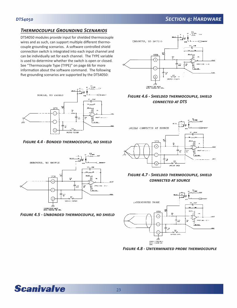
Thermocouple Grounding ScenariosDTS4050 modules provide input for shielded thermocouple wires and as such, can support multiple different thermo-couple grounding scenarios. A software controlled shield connection switch is integrated into each input channel and can be individually set for each channel. The TYPE variable is used to determine whether the switch is open or closed. See “Thermocouple Type (TYPE)” on page 66 for more information about the software command. The following five grounding scenarios are supported by the DTS4050:
Figure 4.4 - Bonded thermocouple, no shield
Figure 4.5 - Unbonded thermocouple, no shield
Figure 4.6 - Shielded thermocouple, shield connected at DTS
Figure 4.7 - Shielded thermocouple, shield connected at source
Figure 4.8 - Unterminated probe thermocouple

24
DTS4050Section 5: Software
[This page intentionally left blank]

25
DTS4050 Section 5: Software
SECTION 5: SOFTWAREDTS Control and ConfigurationThe operation of the DTS is controlled by sending com-mands to each unit in the form of an ASCII string terminated by a CR or LF character. The DTS receives these commands over an Ethernet or serial physical interface. The DTS Ethernet server receives commands via TCP using the Telnet port 23. The serial interface is fixed to receive and transmit at 9600 baud, full duplex, no parity and 8 data bits.
In general, commands do one of the following: 1) Configure the DTS, 2) Return information about the DTS, or 3) Return temperature data.
Commands that configure the DTS do not return any infor-mation. Some commands that take longer to execute put the DTS into a mode until the command is complete.
Commands that return information about the DTS transmit that information back to the same device that requested it over the same physical interface. The term information is used to describe what the DTS returns as the result of non-scan commands. This information is always sent as ASCII strings with each line terminated with a CR or LF.
Commands that return temperature data cause the DTS to go into a Scan Mode. The term “data” is used to describe temperature data read as the result of a scan command. Depending on the configuration, the data may be returned in ASCII formatted with VT100 control characters, ASCII unformatted, or as binary packets. Binary data transfers are delivered across an additional binary transfer port in either UDP or TCP.
TCP Telnet ServerThe DTS supports a Telnet server on port 23. Commands are received and transmitted according to the Telnet speci-fication. All commands must be terminated properly with one of four options. The DTS will detect and adjust to the termination option being used.
The four options are:CR (ASCII 13)LF (ASCII 10)LF-CR (ASCII 10 - ASCII 13)CR-LF (ASCII 13 - ASCII 10)
UDP ID ServerThe purpose of the UDP ID server is to respond to broad-cast packets and return information about each DTS. This is useful in determining the IP address, and other informa-tion, of each DTS on a network.
All commands supported in the Telnet server are also sup-ported by the UDP ID server. Command line terminators are the same as required by the Telnet server.
The UDP ID server receives commands on port 7000. Information is returned on port 7001. Formatted and unfor-matted scan data is not output over the UDP ID server. For more information about data routing see the Data Transfer section.
Serial CommandsCommands may be transmitted to the DTS via a serial RS-232 interface. All commands supported in the Telnet server are also supported by the serial interface. Command line terminators are the same as required by the Telnet server.
Formatted and unformatted scan data is not output over the serial interface. For more information about data rout-ing see the Data Transfer section.
Data Transfer Scan data is routed to different devices based on the con-figuration of the DTS. Some configurations are not allowed and produce errors. Refer to the chart below for the vari-ous output data routing.

26
DTS4050Section 5: Software
DTS 4050 Command and Data Output Matrix
Command Source Command Output Data Output Bin Host CommentTCP / Telnet TCP / Telnet X X Command returned to Telnet
TCP / Telnet (Scan) TCP / Telnet 0 X ASCII Data to Telnet
TCP / Telnet (Scan) TCP to host <IP> 1 <IP>T Binary TCP Data to IP Address
TCP / Telnet (Scan) UDP to host <IP> 1 <IP>U Binary UDP Data to IP Address
Serial Serial X X Command returned to Serial Port
Serial (Scan) ERROR X X Serial data not supported
UDP ID (Port 7000) UDP ID (Port 7000) X X ID Server command back to ID Client
UDP ID (Port 7000) (Scan) ERROR X X ID Server data not supported
27
DTS4050 Section 5: Software
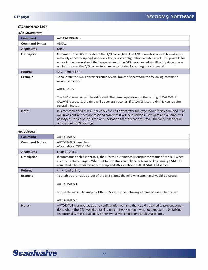
Command ListA/D Calibration
Command A/D CALIBRATIONCommand Syntax ADCALArguments NoneDescription Commands the DTS to calibrate the A/D converters. The A/D converters are calibrated auto-
matically at power up and whenever the period configuration variable is set. It is possible for errors in the conversion if the temperature of the DTS has changed significantly since power up. In this case, the A/D converters can be calibrated by issuing this command.
Returns <nl> - end of lineExample To calibrate the A/D converters after several hours of operation, the following command
would be issued:
ADCAL <CR>
The A/D converters will be calibrated. The time depends upon the setting of CALAVG. If CALAVG is set to 1, the time will be several seconds. If CALAVG is set to 64 this can require several minutes.
Notes It is recommended that a user check for A/D errors after the execution of this command. If an A/D times out or does not respond correctly, it will be disabled in software and an error will be logged. The error log is the only indication that this has occurred. The failed channel will only output 9999 readings.
Auto Status
Command AUTOSTATUSCommand Syntax AUTOSTATUS <enable>
AS <enable> (OPTIONAL)Arguments Enable - 0 or 1Description If autostatus enable is set to 1, the DTS will automatically output the status of the DTS when-
ever the status changes. When set to 0, status can only be determined by issuing a STATUS command. The condition at power up and after a reboot is AUTOSTATUS disabled.
Returns <nl> - end of lineExample To enable automatic output of the DTS status, the following command would be issued:
AUTOSTATUS 1
To disable automatic output of the DTS status, the following command would be issued:
AUTOSTATUS 0Notes AUTOTATUS was not set up as a configuration variable that could be saved to prevent condi-
tions where the DTS would be talking on a network when it was not expected to be talking. An optional syntax is available. Either syntax will enable or disable Autostatus.
28
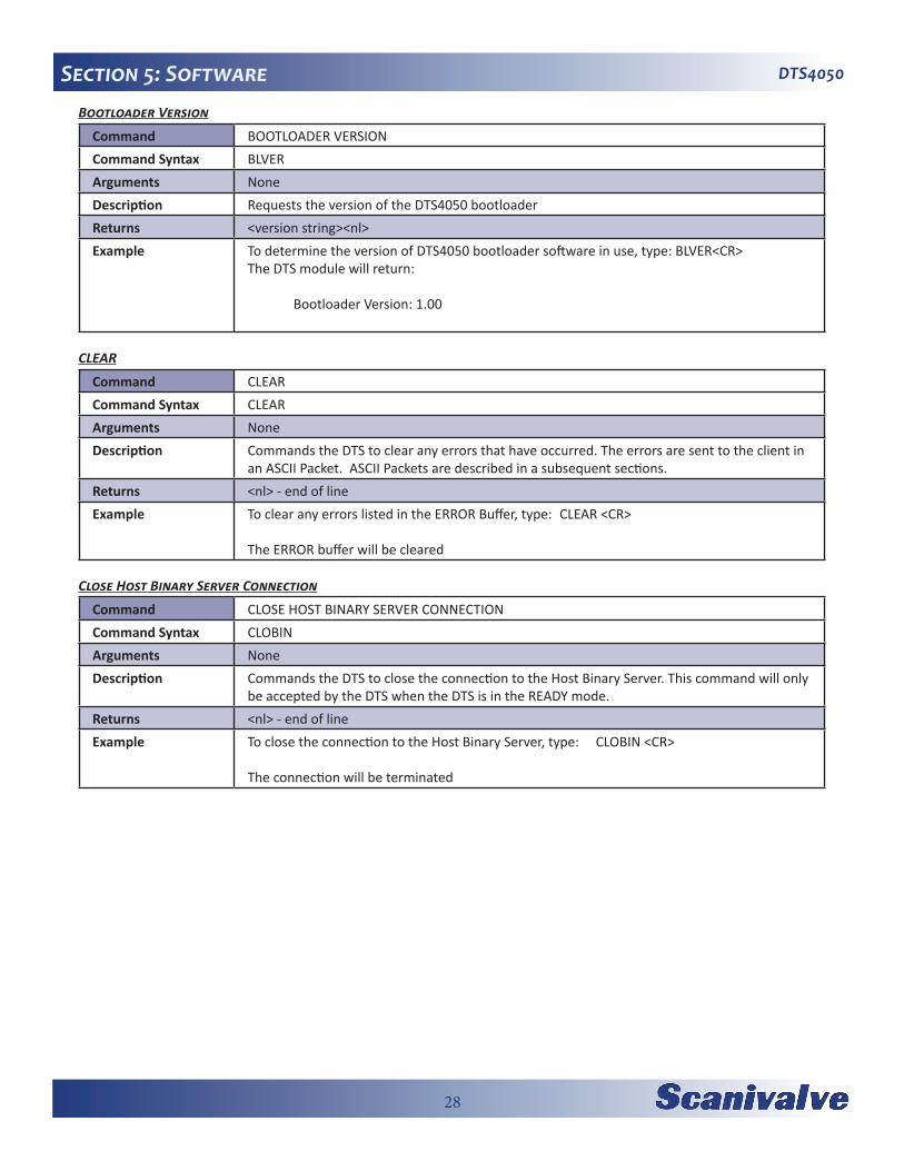
DTS4050Section 5: SoftwareBootloader Version
Command BOOTLOADER VERSIONCommand Syntax BLVERArguments NoneDescription Requests the version of the DTS4050 bootloaderReturns <version string><nl>Example To determine the version of DTS4050 bootloader software in use, type: BLVER<CR>
The DTS module will return:
Bootloader Version: 1.00
CLEAR
Command CLEARCommand Syntax CLEARArguments NoneDescription Commands the DTS to clear any errors that have occurred. The errors are sent to the client in
an ASCII Packet. ASCII Packets are described in a subsequent sections.Returns <nl> - end of lineExample To clear any errors listed in the ERROR Buffer, type: CLEAR <CR>
The ERROR buffer will be cleared
Close Host Binary Server Connection
Command CLOSE HOST BINARY SERVER CONNECTIONCommand Syntax CLOBINArguments NoneDescription Commands the DTS to close the connection to the Host Binary Server. This command will only
be accepted by the DTS when the DTS is in the READY mode.Returns <nl> - end of lineExample To close the connection to the Host Binary Server, type: CLOBIN <CR>
The connection will be terminated
29
DTS4050 Section 5: Software
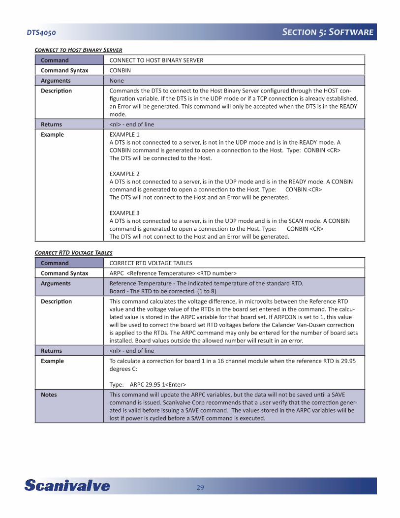
Connect to Host Binary Server
Command CONNECT TO HOST BINARY SERVERCommand Syntax CONBINArguments NoneDescription Commands the DTS to connect to the Host Binary Server configured through the HOST con-
figuration variable. If the DTS is in the UDP mode or if a TCP connection is already established, an Error will be generated. This command will only be accepted when the DTS is in the READY mode.
Returns <nl> - end of lineExample EXAMPLE 1
A DTS is not connected to a server, is not in the UDP mode and is in the READY mode. A CONBIN command is generated to open a connection to the Host. Type: CONBIN <CR> The DTS will be connected to the Host.
EXAMPLE 2A DTS is not connected to a server, is in the UDP mode and is in the READY mode. A CONBIN command is generated to open a connection to the Host. Type: CONBIN <CR> The DTS will not connect to the Host and an Error will be generated.
EXAMPLE 3A DTS is not connected to a server, is in the UDP mode and is in the SCAN mode. A CONBIN command is generated to open a connection to the Host. Type: CONBIN <CR> The DTS will not connect to the Host and an Error will be generated.
Correct RTD Voltage Tables
Command CORRECT RTD VOLTAGE TABLESCommand Syntax ARPC <Reference Temperature> <RTD number>Arguments Reference Temperature - The indicated temperature of the standard RTD.
Board - The RTD to be corrected. (1 to 8)Description This command calculates the voltage difference, in microvolts between the Reference RTD
value and the voltage value of the RTDs in the board set entered in the command. The calcu-lated value is stored in the ARPC variable for that board set. If ARPCON is set to 1, this value will be used to correct the board set RTD voltages before the Calander Van-Dusen correction is applied to the RTDs. The ARPC command may only be entered for the number of board sets installed. Board values outside the allowed number will result in an error.
Returns <nl> - end of lineExample To calculate a correction for board 1 in a 16 channel module when the reference RTD is 29.95
degrees C:
Type: ARPC 29.95 1<Enter>Notes This command will update the ARPC variables, but the data will not be saved until a SAVE
command is issued. Scanivalve Corp recommends that a user verify that the correction gener-ated is valid before issuing a SAVE command. The values stored in the ARPC variables will be lost if power is cycled before a SAVE command is executed.
30
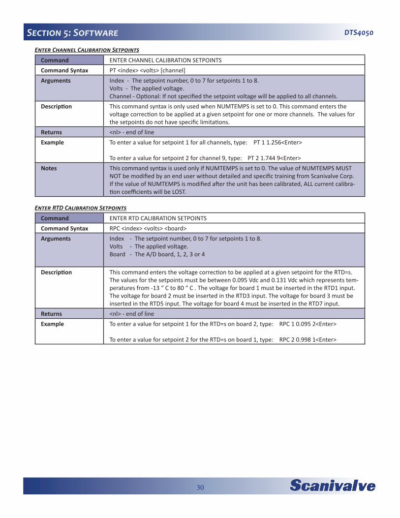
DTS4050Section 5: SoftwareEnter Channel Calibration Setpoints
Command ENTER CHANNEL CALIBRATION SETPOINTSCommand Syntax PT <index> <volts> [channel]Arguments Index - The setpoint number, 0 to 7 for setpoints 1 to 8.
Volts - The applied voltage.Channel - Optional: If not specified the setpoint voltage will be applied to all channels.
Description This command syntax is only used when NUMTEMPS is set to 0. This command enters the voltage correction to be applied at a given setpoint for one or more channels. The values for the setpoints do not have specific limitations.
Returns <nl> - end of lineExample To enter a value for setpoint 1 for all channels, type: PT 1 1.256<Enter>
To enter a value for setpoint 2 for channel 9, type: PT 2 1.744 9<Enter>Notes This command syntax is used only if NUMTEMPS is set to 0. The value of NUMTEMPS MUST
NOT be modified by an end user without detailed and specific training from Scanivalve Corp. If the value of NUMTEMPS is modified after the unit has been calibrated, ALL current calibra-tion coefficients will be LOST.
Enter RTD Calibration Setpoints
Command ENTER RTD CALIBRATION SETPOINTSCommand Syntax RPC <index> <volts> <board> Arguments Index - The setpoint number, 0 to 7 for setpoints 1 to 8.
Volts - The applied voltage.Board - The A/D board, 1, 2, 3 or 4
Description This command enters the voltage correction to be applied at a given setpoint for the RTD=s. The values for the setpoints must be between 0.095 Vdc and 0.131 Vdc which represents tem-peratures from -13 “ C to 80 “ C . The voltage for board 1 must be inserted in the RTD1 input. The voltage for board 2 must be inserted in the RTD3 input. The voltage for board 3 must be inserted in the RTD5 input. The voltage for board 4 must be inserted in the RTD7 input.
Returns <nl> - end of lineExample To enter a value for setpoint 1 for the RTD=s on board 2, type: RPC 1 0.095 2<Enter>
To enter a value for setpoint 2 for the RTD=s on board 1, type: RPC 2 0.998 1<Enter>
31
DTS4050 Section 5: Software
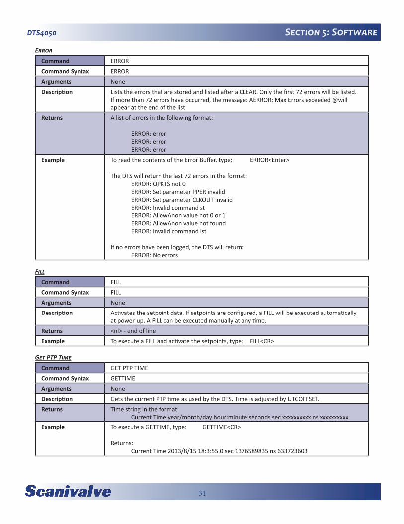
Error
Command ERRORCommand Syntax ERRORArguments NoneDescription Lists the errors that are stored and listed after a CLEAR. Only the first 72 errors will be listed.
If more than 72 errors have occurred, the message: AERROR: Max Errors exceeded @will appear at the end of the list.
Returns A list of errors in the following format:
ERROR: error ERROR: error ERROR: error
Example To read the contents of the Error Buffer, type: ERROR<Enter>
The DTS will return the last 72 errors in the format: ERROR: QPKTS not 0 ERROR: Set parameter PPER invalid ERROR: Set parameter CLKOUT invalid ERROR: Invalid command st ERROR: AllowAnon value not 0 or 1 ERROR: AllowAnon value not found ERROR: Invalid command ist
If no errors have been logged, the DTS will return: ERROR: No errors
Fill
Command FILLCommand Syntax FILLArguments NoneDescription Activates the setpoint data. If setpoints are configured, a FILL will be executed automatically
at power-up. A FILL can be executed manually at any time.Returns <nl> - end of lineExample To execute a FILL and activate the setpoints, type: FILL<CR>
Get PTP Time
Command GET PTP TIMECommand Syntax GETTIMEArguments NoneDescription Gets the current PTP time as used by the DTS. Time is adjusted by UTCOFFSET.Returns Time string in the format:
Current Time year/month/day hour:minute:seconds sec xxxxxxxxxx ns xxxxxxxxxxExample To execute a GETTIME, type: GETTIME<CR>
Returns: Current Time 2013/8/15 18:3:55.0 sec 1376589835 ns 633723603

32
DTS4050Section 5: SoftwareGet UTC Offset
Command GET UTC OFFSETCommand Syntax GETUTCOArguments NoneDescription Gets the current UTC offset.Returns The current UTC offset in seconds, UTC updated flag and Set when UTC offset is valid in the
format:
Current UTC Offset <seconds> <update> <valid>Example To execute a GETUTCO, type: GETUTCO<CR>
Returns: Current UTC Offset 0 1 0
Host Binary Server Command
Command HOST BINARY SERVER COMMANDCommand Syntax HOST <command>Arguments Command - An ASCII command that would be recognized by the Host Binary Server.Description This command will pass a Host Binary Server command through the DTS to the Host Binary
ServerReturns <nl> - end of line
Ice Point Offset Adjustment
Command ICE POINT OFFSET ADJUSTMENTCommand Syntax IPO <start channel> <end channel>Arguments <start channel> - the first channel to be adjusted.
<end channel> - the last channel to be adjustedDescription Commands the DTS to calculate and adjust the offset settings for the channels specified. If an
end channel is not specified, only the start channel will be modified. This command assumes that 0 degrees C is applied to the specified channels. A SAVE command must be issued when this command is completed to make the changes permanent
Returns <nl> - end of line
33
DTS4050 Section 5: Software
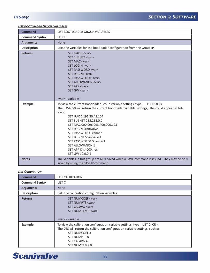
List Bootloader Group Variables
Command LIST BOOTLOADER GROUP VARIABLESCommand Syntax LIST IPArguments NoneDescription Lists the variables for the bootloader configuration from the Group IP.Returns SET IPADD <var>
SET SUBNET <var> SET MAC <var> SET LOGIN <var> SET PASSWORD <var> SET LOGIN1 <var> SET PASSWORD1 <var> SET ALLOWANON <var> SET APP <var> SET GW <var>
<var> - variableExample To view the current Bootloader Group variable settings, type: LIST IP <CR>
The DTS4050 will return the current bootloader variable settings, The could appear as fol-lows: SET IPADD 191.30.41.104 SET SUBNET 255.255.0.0 SET MAC 000.096.093.400.000.103 SET LOGIN Scanivalve SET PASSWORD Scanner SET LOGIN1 Scanivalve1 SET PASSWORD1 Scanner1 SET ALLOWANON 1 SET APP Dts4000.hex SET GW 10.0.0.1
Notes The variables in this group are NOT saved when a SAVE command is issued. They may be only saved by using the SAVEIP command.
List Calibration
Command LIST CALIBRATIONCommand Syntax LIST CArguments NoneDescription Lists the calibration configuration variables.Returns SET NUMCOEF <var>
SET NUMPTS <var> SET CALAVG <var> SET NUMTEMP <var>
<var> - variableExample To view the calibration configuration variable settings, type: LIST C<CR>
The DTS will return the calibration configuration variable settings, such as: SET NUMCOEF 3 SET NUMPTS 8 SET CALAVG 4 SET NUMTEMP 0

34
DTS4050Section 5: SoftwareList Channel Correction Setpoints
Command LIST CHANNEL CORRECTION SETPOINTSCommand Syntax LIST P <channel>Arguments Channel - is any valid channel number from 0 to 16, 32 or 64 depending on the module type.Description Lists the calibration setpoints for the channel listed. If channel 0 is specified, the setpoints for
all channels will be listed.Returns SET PT 1 0 <var1> <var2>
SET PT 1 1 <var1> <var2> SET PT 1 2 <var1> <var2> SET PT 1 3 <var1> <var2> SET PT 1 4 <var1> <var2> SET PT 1 5 <var1> <var2> SET PT 1 6 <var1> <var2> SET PT 1 7 <var1> <var2>
<var> - variableExample To view the calibration setpoints for channel 1:
Type: LIST P 1<CR>The DTS returns: SET PT 1 0 -0.010000 -275283 SET PT 1 1 0.000000 1288 SET PT 1 2 0.012000 333064 SET PT 1 3 0.024000 664759 SET PT 1 4 0.036000 996312 SET PT 1 5 0.048000 1327909 SET PT 1 6 0.060000 1659352 SET PT 1 7 0.070000 1935411
Notes The values shown here are values a typical one module. The actual calibration setpoints in a different module may be different.
This syntax is used only when NUMTEMPS is set to 0.
35
DTS4050 Section 5: Software
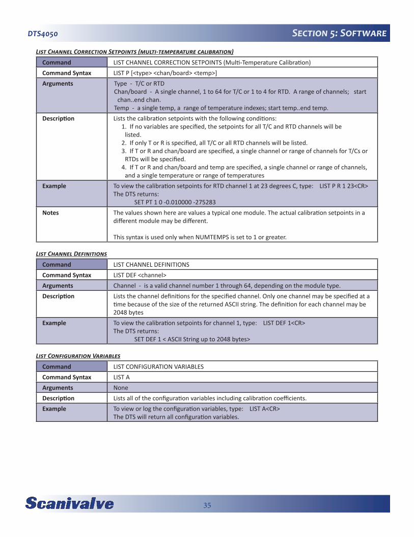
List Channel Correction Setpoints (multi-temperature calibration)
Command LIST CHANNEL CORRECTION SETPOINTS (Multi-Temperature Calibration)Command Syntax LIST P [<type> <chan/board> <temp>]Arguments Type - T/C or RTD
Chan/board - A single channel, 1 to 64 for T/C or 1 to 4 for RTD. A range of channels; start chan..end chan.
Temp - a single temp, a range of temperature indexes; start temp..end temp.Description Lists the calibration setpoints with the following conditions:
1. If no variables are specified, the setpoints for all T/C and RTD channels will be listed.
2. If only T or R is specified, all T/C or all RTD channels will be listed.3. If T or R and chan/board are specified, a single channel or range of channels for T/Cs or
RTDs will be specified.4. If T or R and chan/board and temp are specified, a single channel or range of channels,
and a single temperature or range of temperaturesExample To view the calibration setpoints for RTD channel 1 at 23 degrees C, type: LIST P R 1 23<CR>
The DTS returns: SET PT 1 0 -0.010000 -275283
Notes The values shown here are values a typical one module. The actual calibration setpoints in a different module may be different.
This syntax is used only when NUMTEMPS is set to 1 or greater.
List Channel Definitions
Command LIST CHANNEL DEFINITIONSCommand Syntax LIST DEF <channel>Arguments Channel - is a valid channel number 1 through 64, depending on the module type.Description Lists the channel definitions for the specified channel. Only one channel may be specified at a
time because of the size of the returned ASCII string. The definition for each channel may be 2048 bytes
Example To view the calibration setpoints for channel 1, type: LIST DEF 1<CR>The DTS returns: SET DEF 1 < ASCII String up to 2048 bytes>
List Configuration Variables
Command LIST CONFIGURATION VARIABLESCommand Syntax LIST AArguments NoneDescription Lists all of the configuration variables including calibration coefficients.Example To view or log the configuration variables, type: LIST A<CR>
The DTS will return all configuration variables.

36
DTS4050Section 5: SoftwareList Files
Command LIST FILESCommand Syntax DIRArguments NoneDescription Lists the data files stored in the DTS4050 folder on the DTS4050 system flash chip.Example To list all data files stored on the DTS4050 system computer drive, type: DIRFILE<CR>
The DTS will return a file list, typically similar to: -rw-r--r-- 1 1 217 Aug 1 2008 ip.cfg -rw-r--r-- 1 1 340999 Aug 1 2008 DTS4000.BIT -rw-r--r-- 1 1 610058 Aug 1 2008 Dts4000.hex -rw-r--r-- 1 1 221 Aug 1 2008 ptp.cfg -rw-r--r-- 1 1 25 Aug 1 2008 hw.cfg
List Gain
Command LIST GAINCommand Syntax LIST GArguments NoneDescription Lists the thermocouple gain correction assigned to the channel listed.Example To view the thermocouple gain settings in a 16 channel module, type: LIST G <CR>
The DTS will return all of the thermocouple gain settings. They could appear as follows. SET GAIN 1 1.11 SET GAIN 2 1.01 SET GAIN 3 0.98 : : : : : : : : : : : : : : : : SET GAIN 13 1.06 SET GAIN 14 1.00 SET GAIN 15 0.99 SET GAIN 16 1.10
37
DTS4050 Section 5: Software
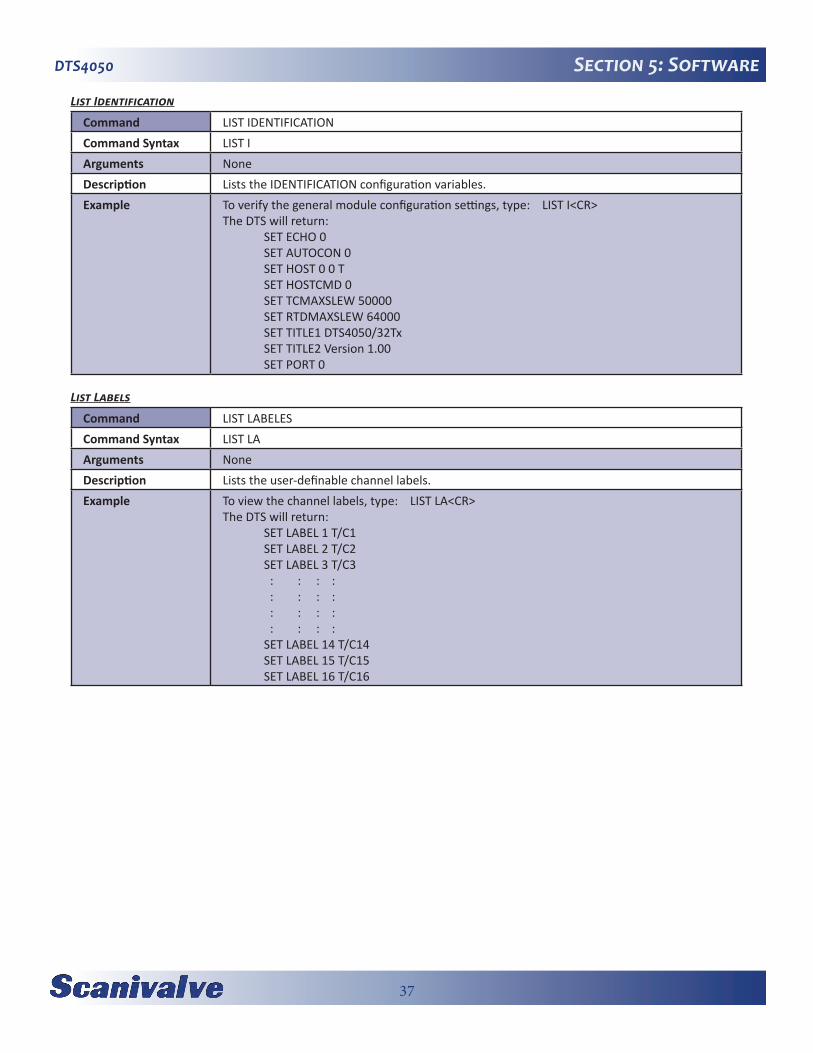
List Identification
Command LIST IDENTIFICATIONCommand Syntax LIST IArguments NoneDescription Lists the IDENTIFICATION configuration variables.Example To verify the general module configuration settings, type: LIST I<CR>
The DTS will return: SET ECHO 0 SET AUTOCON 0 SET HOST 0 0 T SET HOSTCMD 0 SET TCMAXSLEW 50000 SET RTDMAXSLEW 64000 SET TITLE1 DTS4050/32Tx SET TITLE2 Version 1.00 SET PORT 0
List Labels
Command LIST LABELESCommand Syntax LIST LAArguments NoneDescription Lists the user-definable channel labels.Example To view the channel labels, type: LIST LA<CR>
The DTS will return: SET LABEL 1 T/C1 SET LABEL 2 T/C2 SET LABEL 3 T/C3 : : : : : : : : : : : : : : : : SET LABEL 14 T/C14 SET LABEL 15 T/C15 SET LABEL 16 T/C16

38
DTS4050Section 5: SoftwareList Limits
Command LIST LIMITSCommand Syntax LIST LIArguments NoneDescription Lists the channel high and low limits for alarmsExample To verify the channel limit settings for a 16 channel module, type: LIST LI<CR>
The DTS will return: SET LIMIT 1 1 500.00 -50.00 SET LIMIT 2 1 500.00 -50.00 SET LIMIT 3 1 500.00 -50.00 : : : : : : : : : : : : : : : : : : : : : : : : SET LIMIT 13 1 500.00 -50.00 SET LIMIT 14 1 500.00 -50.00 SET LIMIT 15 1 500.00 -50.00 SET LIMIT 16 1 500.00 -50.00
List Network Identification
Command LIST IDENTIFICATIONCommand Syntax LIST IDArguments NoneDescription Lists the MODULE NETWORK IDENTIFICATION configuration variables to support the Network
ID command.Example To verify the Network Identification configuration settings, type: LIST ID<CR>
The DTS will return: SET IPADD <IP address> SET MODEL <Model/channels> SET SERNUM <Serial number> SET VER <Firmware Version>
Notes The variable VER are listed to display current setting only. It cannot be changed by the user from the LIST ID group.
The variable IPADD will only be saved after the SAVEIP command is sent. The SAVE command will not save the IPADD variable.

39
DTS4050 Section 5: Software
List Offset
Command LIST OFFSETCommand Syntax LIST OArguments NoneDescription Lists the thermocouple offset correction assigned to the channel specified. The OFFSET
values are A/D counts.Example To view all of the thermocouple offset settings in a 16 channel module, type: LIST O <CR>
The DTS will return the thermocouple offset settings. They could appear as follows: SET OFFSET 1 120 SET OFFSET 2 77 SET OFFSET 3 78 : : : : : : : : : : : : : : : : SET OFFSET 14 124 SET OFFSET 15 81 SET OFFSET 16 25
List Precision Time Protocol
Command LIST PRECISION TIME PROTOCOLCommand Syntax LIST PTPArguments NoneDescription Lists the variables related to the Group PTP, Precision Time Protocol.Example To view all of the PTP settings, type: LIST PTP<CR>
The DTS will return the current PTP settings. They typically appear as follows. SET PTPEN 0 SET TUNE 10 0.500000 500000 5 SET SLL 1 SET STAT 0 SET SST 0:0:0.000000 SET SSD 1971/1/1 SET UC 1 SET INTERVAL 100000 SET ADJDRIFT 100 100000 SET UTCOFFSET 00:00:00
Notes The variables in this group are NOT saved when a SAVE command is issued. They may be only saved by using the SAVEPTP command.
40
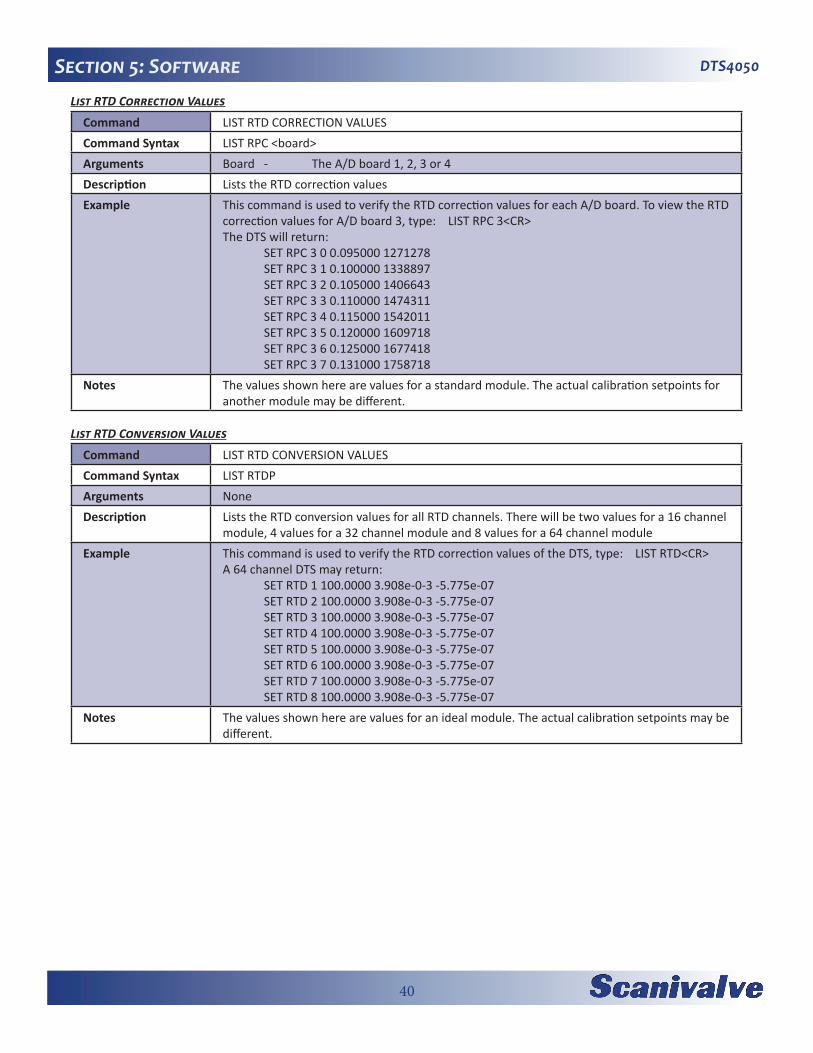
DTS4050Section 5: SoftwareList RTD Correction Values
Command LIST RTD CORRECTION VALUESCommand Syntax LIST RPC <board>Arguments Board - The A/D board 1, 2, 3 or 4Description Lists the RTD correction values Example This command is used to verify the RTD correction values for each A/D board. To view the RTD
correction values for A/D board 3, type: LIST RPC 3<CR>The DTS will return: SET RPC 3 0 0.095000 1271278 SET RPC 3 1 0.100000 1338897 SET RPC 3 2 0.105000 1406643 SET RPC 3 3 0.110000 1474311 SET RPC 3 4 0.115000 1542011 SET RPC 3 5 0.120000 1609718 SET RPC 3 6 0.125000 1677418 SET RPC 3 7 0.131000 1758718
Notes The values shown here are values for a standard module. The actual calibration setpoints for another module may be different.
List RTD Conversion Values
Command LIST RTD CONVERSION VALUESCommand Syntax LIST RTDPArguments NoneDescription Lists the RTD conversion values for all RTD channels. There will be two values for a 16 channel
module, 4 values for a 32 channel module and 8 values for a 64 channel moduleExample This command is used to verify the RTD correction values of the DTS, type: LIST RTD<CR>
A 64 channel DTS may return: SET RTD 1 100.0000 3.908e-0-3 -5.775e-07 SET RTD 2 100.0000 3.908e-0-3 -5.775e-07 SET RTD 3 100.0000 3.908e-0-3 -5.775e-07 SET RTD 4 100.0000 3.908e-0-3 -5.775e-07 SET RTD 5 100.0000 3.908e-0-3 -5.775e-07 SET RTD 6 100.0000 3.908e-0-3 -5.775e-07 SET RTD 7 100.0000 3.908e-0-3 -5.775e-07 SET RTD 8 100.0000 3.908e-0-3 -5.775e-07
Notes The values shown here are values for an ideal module. The actual calibration setpoints may be different.

41
DTS4050 Section 5: Software
List RTD Current Conversion Values
Command LIST RTD CURRENT CONVERSION VALUESCommand Syntax LIST RTDXArguments NoneDescription Lists the RTD current conversion values for all RTD channels. There will be two values for a 16
channel module, 4 values for a 32 channel module and 8 values for a 64 channel module.Example This command is used to verify the RTD current correction values of the DTS. This variable
corrects for errors in the RTD excitation circuit.Type: LIST RTDX<CR>A 64 channel DTS will return: SET RTDX 1 1.0000000 SET RTDX 2 1.0000000 SET RTDX3 1.0000000 SET RTDX 4 1.0000000 SET RTDX 5 1.0000000 SET RTDX 6 1.0000000 SET RTDX7 1.0000000 SET RTDX 8 1.0000000
Notes The values shown here are values for an ideal RTD excitation circuit. The actual values may be different.
List Scan Variables
Command LIST SCAN VARIABLESCommand Syntax LIST SArguments NoneDescription Lists the SCAN configuration variables.Example This command is used to verify the general scan settings of the DTS, type: LIST S<CR>
The DTS will return: SET PERIOD 1562.50000 SET AVG 4 SET FPS 0 SET XSCANTRIG 0 SET FORMAT 0 SET TIME 2 SET BIN 0 SET QPKTS 0 SET UNITS C SET RANGEV -9999.999 9999.999 SET RANGET -9999.99 9999.99 SET RATE 5.0000
42
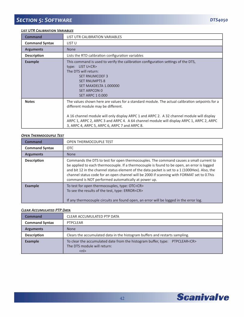
DTS4050Section 5: SoftwareList UTR Calibration Variables
Command LIST UTR CALIBRATION VARIABLESCommand Syntax LIST UArguments NoneDescription Lists the RTD calibration configuration variables Example This command is used to verify the calibration configuration settings of the DTS,
type: LIST U<CR>The DTS will return: SET RNUMCOEF 3 SET RNUMPTS 8 SET MAXDELTA 1.000000 SET ARPCON 0 SET ARPC 1 0.000
Notes The values shown here are values for a standard module. The actual calibration setpoints for a different module may be different.
A 16 channel module will only display ARPC 1 and ARPC 2. A 32 channel module will display ARPC 1, ARPC 2, ARPC 3 and ARPC 4. A 64 channel module will display ARPC 1, ARPC 2, ARPC 3, ARPC 4, ARPC 5, ARPC 6, ARPC 7 and ARPC 8.
Open Thermocouple Test
Command OPEN THERMOCOUPLE TESTCommand Syntax OTCArguments NoneDescription Commands the DTS to test for open thermocouples. The command causes a small current to
be applied to each thermocouple. If a thermocouple is found to be open, an error is logged and bit 12 in the channel status element of the data packet is set to a 1 (1000Hex). Also, the channel status code for an open channel will be 2000 if scanning with FORMAT set to 0.This command is NOT performed automatically at power up.
Example To test for open thermocouples, type: OTC<CR>To see the results of the test, type: ERROR<CR>
If any thermocouple circuits are found open, an error will be logged in the error log.
Clear Accumulated PTP Data
Command CLEAR ACCUMULATED PTP DATACommand Syntax PTPCLEARArguments NoneDescription Clears the accumulated data in the histogram buffers and restarts sampling.Example To clear the accumulated date from the histogram buffer, type: PTPCLEAR<CR>
The DTS module will return: <nl>
43
DTS4050 Section 5: Software
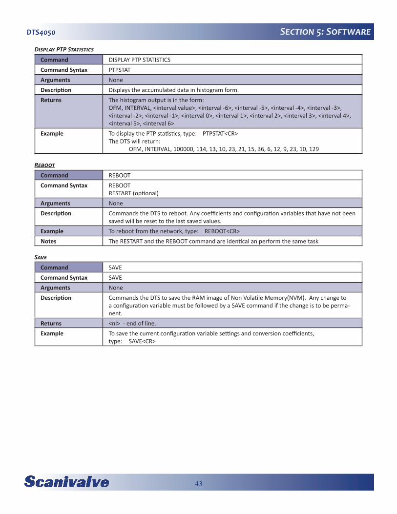
Display PTP Statistics
Command DISPLAY PTP STATISTICSCommand Syntax PTPSTATArguments NoneDescription Displays the accumulated data in histogram form.Returns The histogram output is in the form:
OFM, INTERVAL, <interval value>, <interval -6>, <interval -5>, <interval -4>, <interval -3>, <interval -2>, <interval -1>, <interval 0>, <interval 1>, <interval 2>, <interval 3>, <interval 4>, <interval 5>, <interval 6>
Example To display the PTP statistics, type: PTPSTAT<CR>The DTS will return: OFM, INTERVAL, 100000, 114, 13, 10, 23, 21, 15, 36, 6, 12, 9, 23, 10, 129
Reboot
Command REBOOTCommand Syntax REBOOT
RESTART (optional)Arguments NoneDescription Commands the DTS to reboot. Any coefficients and configuration variables that have not been
saved will be reset to the last saved values.Example To reboot from the network, type: REBOOT<CR>Notes The RESTART and the REBOOT command are identical an perform the same task
Save
Command SAVECommand Syntax SAVEArguments NoneDescription Commands the DTS to save the RAM image of Non Volatile Memory(NVM). Any change to
a configuration variable must be followed by a SAVE command if the change is to be perma-nent.
Returns <nl> - end of line.Example To save the current configuration variable settings and conversion coefficients,
type: SAVE<CR>

44
DTS4050Section 5: SoftwareSave Bootloader Variables
Command SAVE BOOTLOADER VARIABLESCommand Syntax SAVEIPArguments NoneDescription Commands the DTS to save the current settings for the LIST IP variables from RAM into Non
Volatile Memory (NVM). Any change to a configuration variable in the LIST IP group must be followed by a SAVEIP command if the change is to be permanent.
Returns “WARNING: This action could cause network communication problem. Type SAVEIPCONFIRM to confirm the changes to the LIST IP group, or STOP to cancel the operation”<nl> - End of line.
Example To save the current configuration of the LIST IP variables, type: SAVEIP<CR>
The software will return the following message:“WARNING: This action could cause network communication problem. Type SAVEIPCONFIRM to confirm the changes to the LIST IP group, or STOP to cancel the operation”
Type: SAVEIPCONFIRM<CR> to complete the save.Notes Changes to the bootloader configuration variables wil not take effect until power is cycled, or
a REBOOT command is issues.
The SAVEIP command may require approximately 5 seconds to complete, depend¬ing on the configuration. DO NOT issue a RESTART command, or cycle power during this time. The SAVEIP operation has been completed when a caret (>) is returned. Normally, commands entered during this time would be ignored, but it is possible on rare occasions to cause the DTS4050 firmware to freeze.
Save PTP Variables
Command SAVE PTP VARIABLESCommand Syntax SAVEPTPArguments NoneDescription Commands the DTS to save the current settings for the LIST PTP variables from RAM into Non
Volatile Memory (NVM). Any change to a configuration variable in the LIST PTP group must be followed by a SAVEPTP command if the change is to be permanent.
Returns <nl> - End of line.Example To save the current configuration settings from the LIST PTP group, type: SAVEPTP<CR>

45
DTS4050 Section 5: Software
Scan
Command SCANCommand Syntax SCANArguments NoneDescription Commands the DTS to scan the pressure sensors and send Scan packets to the client. Data are
returned immediately if XSCANTRIG is set to 0. If XSCANTRIG is set to 1, data will be returned after a hardware trigger, or a software trigger. For more information on software triggers, refer to the SCAN TRIGGER command. For Hardware trigger requirements, refer to the Trig-ger Requirements section.
Returns Scan data formatted by the setting of EU, BIN, and FORMAT. Refer to the examples for more information. When FORMAT is set to 0, a channel status code will be returned with the data for each channel. If multiple errors exist the code with the highest priority will be the only code displayed
Status Code Description Priority1000 Channel A/D is disabled 12000 Channel T/C is open 23000 Channel is over range 34000 Channel is under range 45000 Channel is over limit 56000 Channel is under limit 6
...continued...

46
DTS4050Section 5: Software
Example EXAMPLE 1 EU = 1 BIN = 0 FORMAT= 0.Data is scrolled and will be displayed as follows: Frame # <number> Time <time> <μs or ms> Rtd1 <temp> : : RtdMax <temp> Units <unit> <chan 1> <temp eu> <channel status code> : : : <chan Max> <temp eu> <channel status code> EXAMPLE 2 EU = 0 BIN = 0 FORMAT= 0 Data is scrolled and will be displayed as follows: Frame # <number> Time <time> <μs or ms> Rtd1 <temp counts> RtdMax <temp counts Units <unit> <chan 1> <temp counts> <channel status code> : : : <chan Max> <temp counts> <channel status code>
EXAMPLE 3 EU = 1 BIN = 0 FORMAT = 1 Data is scrolled in place and will be displayed as follows: Frame = <number> Time = <time> <μs or ms> Units = <unit> RTD1 <temp> ........... RTDMax <temp <chan> <temp eu> <chan><temp eu> <chan> <temp eu> <chan> <temp eu> <chan> <temp eu> <chan><temp eu> <chan> <temp eu> <chan> <temp eu> <chan> <temp eu> <chan><temp eu> <chan> <temp eu> <chan> <temp eu> : : : : : : : : <chan> <temp eu> <chan><temp eu> <chan> <temp eu> <chan> <temp eu>
EXAMPLE 4 EU = 0 BIN = 0 FORMAT = 1 Data is scrolled and will be displayed as follows: Frame = <number> Time = <time> <μs or ms> Units = <unit> RTD1 <counts>............RTDMax <counts> <chan> <temp cts> <chan><temp cts> <chan> <temp cts> <chan> <temp cts> <chan> <temp cts> <chan><temp cts> <chan> <temp cts> <chan> <temp cts> <chan> <temp cts> <chan><temp cts> <chan> <temp cts> <chan> <temp cts> : : : : : : : : <chan> <temp cts> <chan><temp cts> <chan> <temp cts> <chan> <temp cts>
...continued...
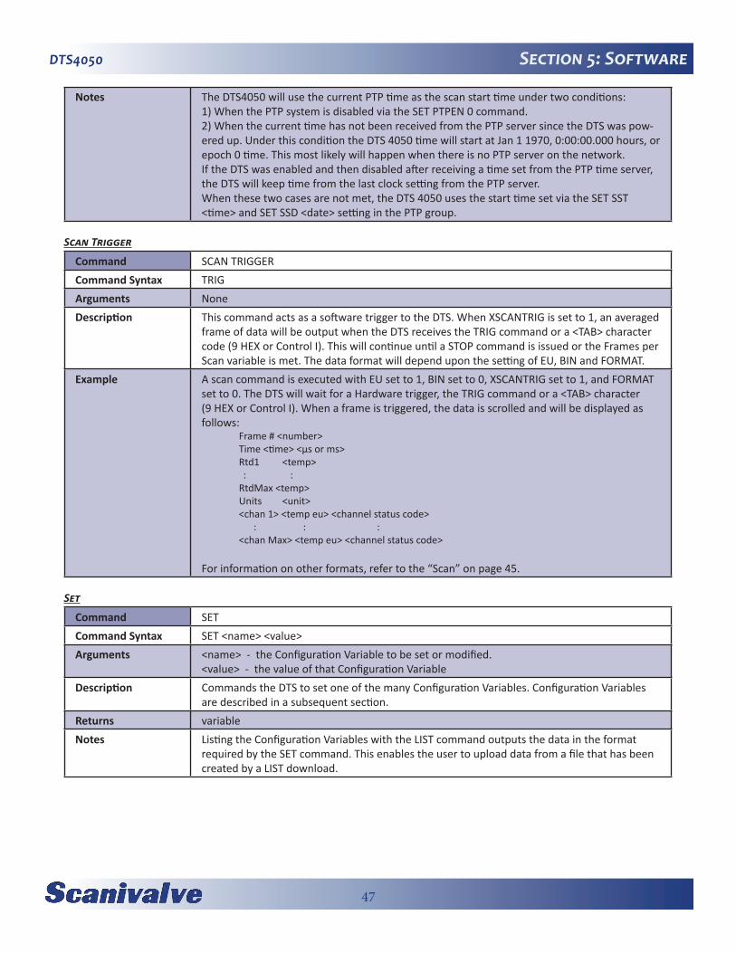
47
DTS4050 Section 5: Software
Notes The DTS4050 will use the current PTP time as the scan start time under two conditions:1) When the PTP system is disabled via the SET PTPEN 0 command.2) When the current time has not been received from the PTP server since the DTS was pow-ered up. Under this condition the DTS 4050 time will start at Jan 1 1970, 0:00:00.000 hours, or epoch 0 time. This most likely will happen when there is no PTP server on the network.If the DTS was enabled and then disabled after receiving a time set from the PTP time server, the DTS will keep time from the last clock setting from the PTP server.When these two cases are not met, the DTS 4050 uses the start time set via the SET SST <time> and SET SSD <date> setting in the PTP group.
Scan Trigger
Command SCAN TRIGGERCommand Syntax TRIGArguments NoneDescription This command acts as a software trigger to the DTS. When XSCANTRIG is set to 1, an averaged
frame of data will be output when the DTS receives the TRIG command or a <TAB> character code (9 HEX or Control I). This will continue until a STOP command is issued or the Frames per Scan variable is met. The data format will depend upon the setting of EU, BIN and FORMAT.
Example A scan command is executed with EU set to 1, BIN set to 0, XSCANTRIG set to 1, and FORMAT set to 0. The DTS will wait for a Hardware trigger, the TRIG command or a <TAB> character (9 HEX or Control I). When a frame is triggered, the data is scrolled and will be displayed as follows: Frame # <number> Time <time> <μs or ms> Rtd1 <temp> : : RtdMax <temp> Units <unit> <chan 1> <temp eu> <channel status code> : : : <chan Max> <temp eu> <channel status code>
For information on other formats, refer to the “Scan” on page 45.
Set
Command SETCommand Syntax SET <name> <value>Arguments <name> - the Configuration Variable to be set or modified.
<value> - the value of that Configuration VariableDescription Commands the DTS to set one of the many Configuration Variables. Configuration Variables
are described in a subsequent section.Returns variableNotes Listing the Configuration Variables with the LIST command outputs the data in the format
required by the SET command. This enables the user to upload data from a file that has been created by a LIST download.
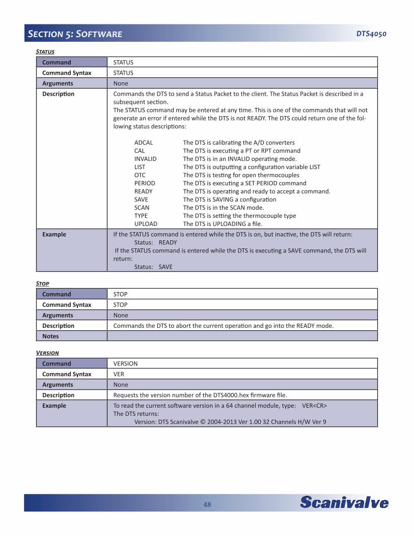
48
DTS4050Section 5: SoftwareStatus
Command STATUSCommand Syntax STATUSArguments NoneDescription Commands the DTS to send a Status Packet to the client. The Status Packet is described in a
subsequent section.The STATUS command may be entered at any time. This is one of the commands that will not generate an error if entered while the DTS is not READY. The DTS could return one of the fol-lowing status descriptions:
ADCAL The DTS is calibrating the A/D converters CAL The DTS is executing a PT or RPT command INVALID The DTS is in an INVALID operating mode. LIST The DTS is outputting a configuration variable LIST OTC The DTS is testing for open thermocouples PERIOD The DTS is executing a SET PERIOD command READY The DTS is operating and ready to accept a command. SAVE The DTS is SAVING a configuration SCAN The DTS is in the SCAN mode. TYPE The DTS is setting the thermocouple type UPLOAD The DTS is UPLOADING a file.
Example If the STATUS command is entered while the DTS is on, but inactive, the DTS will return: Status: READY If the STATUS command is entered while the DTS is executing a SAVE command, the DTS will return: Status: SAVE
Stop
Command STOPCommand Syntax STOPArguments NoneDescription Commands the DTS to abort the current operation and go into the READY mode.Notes
Version
Command VERSIONCommand Syntax VERArguments NoneDescription Requests the version number of the DTS4000.hex firmware file.Example To read the current software version in a 64 channel module, type: VER<CR>
The DTS returns: Version: DTS Scanivalve © 2004-2013 Ver 1.00 32 Channels H/W Ver 9
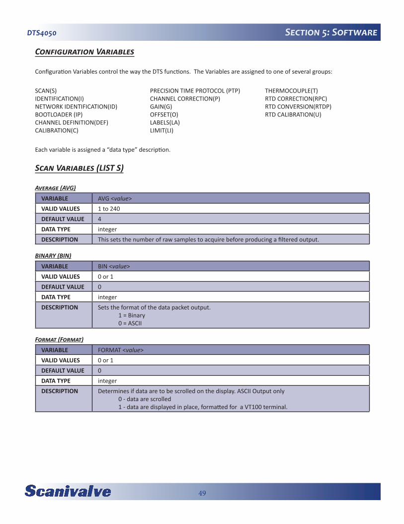
49
DTS4050 Section 5: Software
Configuration Variables
Configuration Variables control the way the DTS functions. The Variables are assigned to one of several groups:
SCAN(S)IDENTIFICATION(I)NETWORK IDENTIFICATION(ID)BOOTLOADER (IP)CHANNEL DEFINITION(DEF)CALIBRATION(C)
PRECISION TIME PROTOCOL (PTP)CHANNEL CORRECTION(P)GAIN(G)OFFSET(O)LABELS(LA)LIMIT(LI)
THERMOCOUPLE(T)RTD CORRECTION(RPC)RTD CONVERSION(RTDP)RTD CALIBRATION(U)
Each variable is assigned a “data type” description.
Scan Variables (LIST S)
Average (AVG)
VARIABLE AVG <value>VALID VALUES 1 to 240DEFAULT VALUE 4DATA TYPE integerDESCRIPTION This sets the number of raw samples to acquire before producing a filtered output.
BINARY (BIN)
VARIABLE BIN <value>VALID VALUES 0 or 1DEFAULT VALUE 0DATA TYPE integerDESCRIPTION Sets the format of the data packet output.
1 = Binary 0 = ASCII
Format (Format)
VARIABLE FORMAT <value>VALID VALUES 0 or 1DEFAULT VALUE 0DATA TYPE integerDESCRIPTION Determines if data are to be scrolled on the display. ASCII Output only
0 - data are scrolled 1 - data are displayed in place, formatted for a VT100 terminal.

50
DTS4050Section 5: SoftwareFrames Per Scan (FPS)
VARIABLE FPS <value>VALID VALUES 0 to 4294967295DEFAULT VALUE 0DATA TYPE long integerDESCRIPTION Sets the number of averaged frames to send to the client. If a 0 is entered, the scan will continue
until a STOP command is received.
Period (Period)
VARIABLE PERIOD <value>VALID VALUES 781 to 262144 μsec (64 Channel versions)
781 to 524288 μsec (32 Channel Versions)781 to 1048576 μsec (16 Channel Versions)
DEFAULT VALUE 7812DATA TYPE floatDESCRIPTION Sets the interval between channel samples (inter-channel delay).
The maximum settings for each version represent the rate limits when AVG is set to 1. The rate limits are: 16 Channels - 80 Hz/Channel 32 Channels - 40 Hz/Channel 64 Channels - 20 Hz/Channel
QPKTS (QPKTS)
VARIABLE QPKTS <value>VALID VALUES 0DEFAULT VALUE 0DATA TYPE integerDESCRIPTION This is a non-functioning variable left in place for legacy compatibility.
Temperature Range Over Range Values (RANGET)
VARIABLE RANGET <low range temp value> <high range temp value>VALID VALUES -9999.99 to 9999.99DEFAULT VALUE Low range temp value - -9999.99
High range temp value - 9999.99DATA TYPE integerDESCRIPTION Sets the output when units is set to a temperature and the high and/or low range limits are
exceeded. When a channel exceeds the low limit, the data display will be setting of the low range value and the channel status code will indicate 4000. When the high limit is exceeded, the data display will be setting of the high range value and the channel status code will indicate 3000.
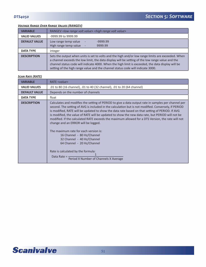
51
DTS4050 Section 5: Software
Voltage Range Over Range Values (RANGEV)
VARIABLE RANGEV <low range volt value> <high range volt value>VALID VALUES -9999.99 to 9999.99DEFAULT VALUE Low range temp value - -9999.99
High range temp value - 9999.99DATA TYPE integerDESCRIPTION Sets the output when units is set to volts and the high and/or low range limits are exceeded. When
a channel exceeds the low limit, the data display will be setting of the low range value and the channel status code will indicate 4000. When the high limit is exceeded, the data display will be setting of the high range value and the channel status code will indicate 3000.
Scan Rate (RATE)
VARIABLE RATE <value>VALID VALUES .01 to 80 (16 channel), .01 to 40 (32 channel), .01 to 20 (64 channel)DEFAULT VALUE Depends on the number of channelsDATA TYPE floatDESCRIPTION Calculates and modifies the setting of PERIOD to give a data output rate in samples per channel per
second. The setting of AVG is included in the calculation but is not modified. Conversely, if PERIOD is modified, RATE will be updated to show the data rate based on that setting of PERIOD. If AVG is modified, the value of RATE will be updated to show the new data rate, but PERIOD will not be modified. If the calculated RATE exceeds the maximum allowed for a DTS Version, the rate will not change and an ERROR will be logged.
The maximum rate for each version is: 16 Channel - 80 Hz/Channel 32 Channel - 40 Hz/Channel 64 Channel - 20 Hz/Channel
Rate is calculated by the formula:Data Rate = 1
Period X Number of Channels X Average
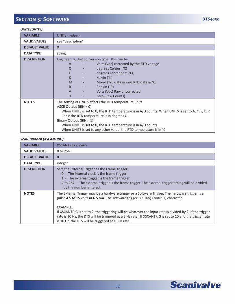
52
DTS4050Section 5: SoftwareUnits (UNITS)
VARIABLE UNITS <value>VALID VALUES see “description”DEFAULT VALUE 0DATA TYPE stringDESCRIPTION Engineering Unit conversion type. This can be :
A - Volts (Vdc) corrected by the RTD voltage C - degrees Celsius (°C) F - degrees Fahrenheit (°F), K - Kelvin (°K) M - Mixed (T/C data in raw, RTD data in °C) R - Rankin (°R) V - Volts (Vdc) Raw uncorrected 0 - Zero (Raw Counts)
NOTES The setting of UNITS affects the RTD temperature units. ASCII Output (BIN = 0):
When UNITS is set to 0, the RTD temperature is in A/D counts. When UNITS is set to A, C, F, K, R or V the RTD temperature is in degrees C.
Binary Output (BIN = 1):When UNITS is set to 0, the RTD temperature is in A/D countsWhen UNITS is set to any other value, the RTD temperature is in °C.
Scan Trigger (XSCANTRIG)
VARIABLE XSCANTRIG <code>VALID VALUES 0 to 254DEFAULT VALUE 0DATA TYPE integerDESCRIPTION Sets the External Trigger as the Frame Trigger.
0 - The internal clock is the frame trigger1 - The external trigger is the frame trigger2 to 254 - The external trigger is the frame trigger. The external trigger timing will be divided
by the number entered. NOTES The External Trigger may be a hardware trigger or a Software Trigger. The hardware trigger is a
pulse 4.5 to 15 volts at 6.5 mA. The software trigger is a Tab( Control I) character.
EXAMPLE:If XSCANTRIG is set to 2, the triggering will be whatever the input rate is divided by 2. If the trigger rate is 10 Hz, the DTS will be triggered at a 5 Hz rate. If XSCANTRIG is set to 10 and the trigger rate is 10 Hz, the DTS will be triggered at a I Hz rate.
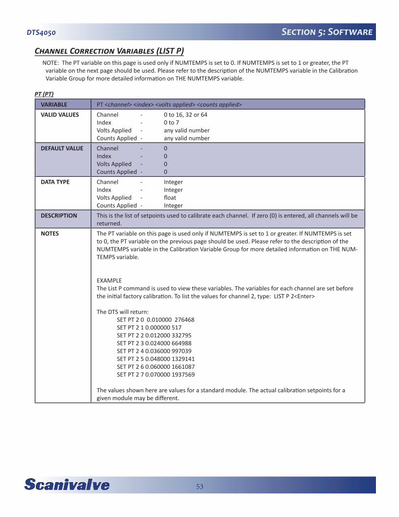
53
DTS4050 Section 5: Software
Channel Correction Variables (LIST P)NOTE: The PT variable on this page is used only if NUMTEMPS is set to 0. If NUMTEMPS is set to 1 or greater, the PT
variable on the next page should be used. Please refer to the description of the NUMTEMPS variable in the Calibration Variable Group for more detailed information on THE NUMTEMPS variable.
PT (PT)
VARIABLE PT <channel> <index> <volts applied> <counts applied>VALID VALUES Channel - 0 to 16, 32 or 64
Index - 0 to 7Volts Applied - any valid numberCounts Applied - any valid number
DEFAULT VALUE Channel - 0Index - 0Volts Applied - 0Counts Applied - 0
DATA TYPE Channel - IntegerIndex - IntegerVolts Applied - floatCounts Applied - Integer
DESCRIPTION This is the list of setpoints used to calibrate each channel. If zero (0) is entered, all channels will be returned.
NOTES The PT variable on this page is used only if NUMTEMPS is set to 1 or greater. If NUMTEMPS is set to 0, the PT variable on the previous page should be used. Please refer to the description of the NUMTEMPS variable in the Calibration Variable Group for more detailed information on THE NUM-TEMPS variable.
EXAMPLEThe List P command is used to view these variables. The variables for each channel are set before the initial factory calibration. To list the values for channel 2, type: LIST P 2<Enter>
The DTS will return: SET PT 2 0 0.010000 276468 SET PT 2 1 0.000000 517 SET PT 2 2 0.012000 332795 SET PT 2 3 0.024000 664988 SET PT 2 4 0.036000 997039 SET PT 2 5 0.048000 1329141 SET PT 2 6 0.060000 1661087 SET PT 2 7 0.070000 1937569
The values shown here are values for a standard module. The actual calibration setpoints for a given module may be different.
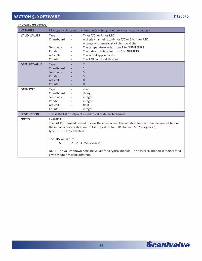
54
DTS4050Section 5: SoftwarePT <type> (PT <type>)
VARIABLE PT <type> <chan/board> <temp ndx> <temp> <pt ndx> <act volts> <counts>VALID VALUES Type - T (for T/C) or R (for RTD)
Chan/board - A single channel, 1 to 64 for T/C or 1 to 4 for RTD A range of channels, start chan..end chanTemp ndx - The temperature index from 1 to NUMTEMPSPt ndx - The index of this point from 1 to NUMPTSAct volts - The actual applied voltsCounts - The A/D counts at this point
DEFAULT VALUE Type - TChan/board - 1Temp ndx - 5Pt ndx - 5Act volts - 0Counts - 0
DATA TYPE Type - charChan/board - stringTemp ndx - integerPt ndx - integerAct volts - floatCounts - integer
DESCRIPTION This is the list of setpoints used to calibrate each channel.NOTES EXAMPLE
The List P command is used to view these variables. The variables for each channel are set before the initial factory calibration. To list the values for RTD channel 2at 23 degrees C, type: LIST P R 2 23<Enter>
The DTS will return: SET PT R 2 3 23 3 .256 276468
NOTE: The values shown here are values for a typical module. The actual calibration setpoints for a given module may be different.
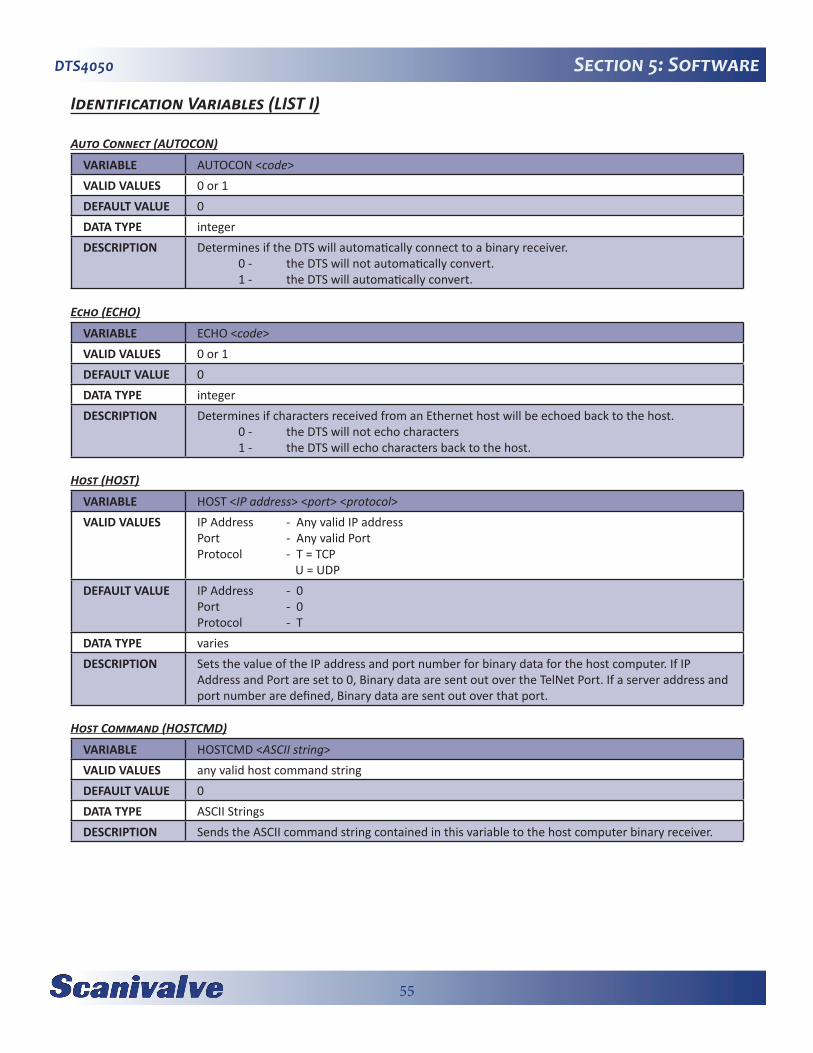
55
DTS4050 Section 5: Software
Identification Variables (LIST I)
Auto Connect (AUTOCON)
VARIABLE AUTOCON <code>VALID VALUES 0 or 1DEFAULT VALUE 0DATA TYPE integerDESCRIPTION Determines if the DTS will automatically connect to a binary receiver.
0 - the DTS will not automatically convert. 1 - the DTS will automatically convert.
Echo (ECHO)
VARIABLE ECHO <code>VALID VALUES 0 or 1DEFAULT VALUE 0DATA TYPE integerDESCRIPTION Determines if characters received from an Ethernet host will be echoed back to the host.
0 - the DTS will not echo characters 1 - the DTS will echo characters back to the host.
Host (HOST)
VARIABLE HOST <IP address> <port> <protocol>VALID VALUES IP Address - Any valid IP address
Port - Any valid Port Protocol - T = TCP U = UDP
DEFAULT VALUE IP Address - 0Port - 0Protocol - T
DATA TYPE variesDESCRIPTION Sets the value of the IP address and port number for binary data for the host computer. If IP
Address and Port are set to 0, Binary data are sent out over the TelNet Port. If a server address and port number are defined, Binary data are sent out over that port.
Host Command (HOSTCMD)
VARIABLE HOSTCMD <ASCII string> VALID VALUES any valid host command stringDEFAULT VALUE 0DATA TYPE ASCII StringsDESCRIPTION Sends the ASCII command string contained in this variable to the host computer binary receiver.

56
DTS4050Section 5: SoftwarePort (PORT)
VARIABLE PORT <value>VALID VALUES 0DEFAULT VALUE 0DATA TYPE integerDESCRIPTION Sets the Ethernet port. With PORT set to 0, it uses the default value, 23 which is the TelNet port.
RTD Maximum Slew Limit (RTDMAXSLEW)
VARIABLE RTDMAXSLEW <value> VALID VALUES 0 to 32000DEFAULT VALUE 0DATA TYPE integerDESCRIPTION This is a non-functional variable left in place for legacy compatibility
Thermocouple Maximum Slew Limit (TCMAXSLEW)
VARIABLE TCMAXSLEW <value> VALID VALUES 0 to 3000000DEFAULT VALUE 0DATA TYPE integerDESCRIPTION This is a non-functional variable left in place for legacy compatibility
Title 1 (TITLE1)
VARIABLE TITLE1 <title>VALID VALUES any valid ASCII string up to 255 charactersDEFAULT VALUE Scanivalve DTS4000DATA TYPE ASCII StringDESCRIPTION Sets the value of Title number 1.
Title 2 (TITLE2)
VARIABLE TITLE2 <title>VALID VALUES any valid ASCII string up to 255 charactersDEFAULT VALUE The current software versionDATA TYPE ASCII StringDESCRIPTION Sets the value of Title number 2.
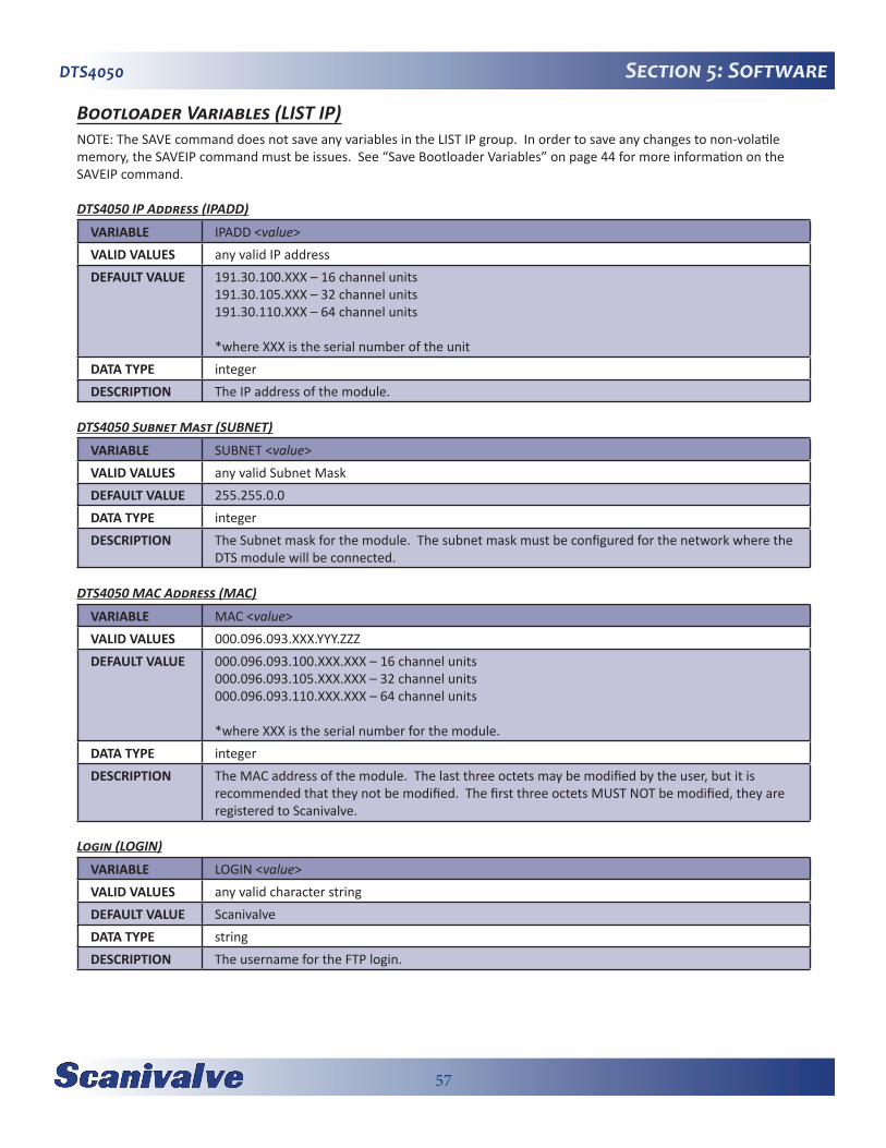
57
DTS4050 Section 5: Software
Bootloader Variables (LIST IP)NOTE: The SAVE command does not save any variables in the LIST IP group. In order to save any changes to non-volatile memory, the SAVEIP command must be issues. See “Save Bootloader Variables” on page 44 for more information on the SAVEIP command.
DTS4050 IP Address (IPADD)
VARIABLE IPADD <value>VALID VALUES any valid IP addressDEFAULT VALUE 191.30.100.XXX – 16 channel units
191.30.105.XXX – 32 channel units191.30.110.XXX – 64 channel units
*where XXX is the serial number of the unitDATA TYPE integerDESCRIPTION The IP address of the module.
DTS4050 Subnet Mast (SUBNET)
VARIABLE SUBNET <value>VALID VALUES any valid Subnet MaskDEFAULT VALUE 255.255.0.0DATA TYPE integerDESCRIPTION The Subnet mask for the module. The subnet mask must be configured for the network where the
DTS module will be connected.
DTS4050 MAC Address (MAC)
VARIABLE MAC <value>VALID VALUES 000.096.093.XXX.YYY.ZZZDEFAULT VALUE 000.096.093.100.XXX.XXX – 16 channel units
000.096.093.105.XXX.XXX – 32 channel units000.096.093.110.XXX.XXX – 64 channel units
*where XXX is the serial number for the module.DATA TYPE integerDESCRIPTION The MAC address of the module. The last three octets may be modified by the user, but it is
recommended that they not be modified. The first three octets MUST NOT be modified, they are registered to Scanivalve.
Login (LOGIN)
VARIABLE LOGIN <value>VALID VALUES any valid character stringDEFAULT VALUE ScanivalveDATA TYPE stringDESCRIPTION The username for the FTP login.

58
DTS4050Section 5: SoftwarePassword (PASSWORD)
VARIABLE PASSWORD <value>VALID VALUES any valid character stringDEFAULT VALUE ScannerDATA TYPE stringDESCRIPTION The password associated with the user name for the FTP login.
Login 1 (LOGIN1)
VARIABLE LOGIN1 <value>VALID VALUES any valid character stringDEFAULT VALUE Scanivalve1DATA TYPE stringDESCRIPTION The username for the FTP login.
Password 1 (PASSWORD1)
VARIABLE PASSWORD <value>VALID VALUES any valid character stringDEFAULT VALUE ScannerDATA TYPE string1DESCRIPTION The password associated with the user name for the FTP login.
Allow Anonymous Logon (ALLOWANON)
VARIABLE ALLOWANON <value>VALID VALUES 0 or 1DEFAULT VALUE 0DATA TYPE integerDESCRIPTION Determines the new line character(s) for all output.
0 – Do not allow anonymous FTP logins 1 – Allow anonymous FTP logins
Application File (APP)
VARIABLE APP <value>VALID VALUES any valid application nameDEFAULT VALUE Dts4000.hexDATA TYPE stringDESCRIPTION The file name of the application to run. This is the file name that is used when automatically
running the application from the boot loader. It is also the file name used when using the RUN command. If this file is not found, an error is returned. Note that this entry is case sensitive.
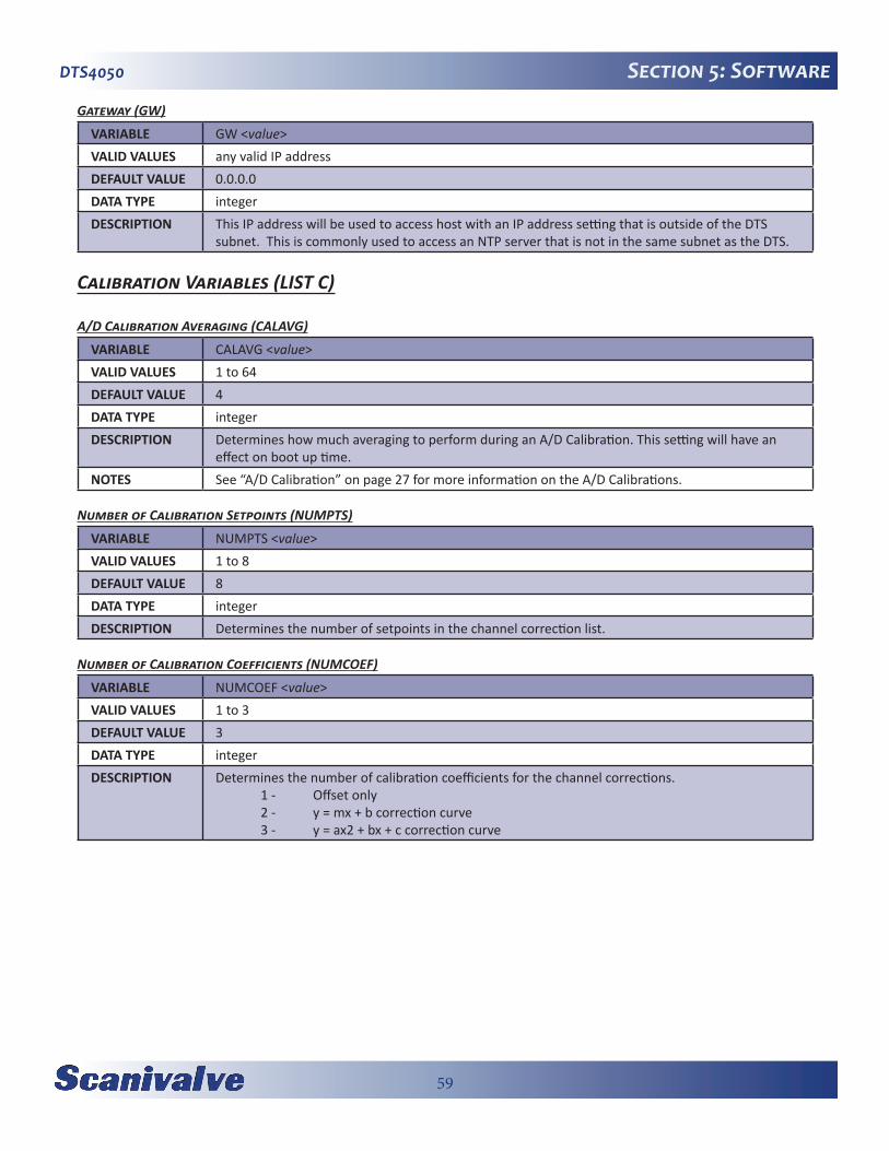
59
DTS4050 Section 5: Software
Gateway (GW)
VARIABLE GW <value>VALID VALUES any valid IP addressDEFAULT VALUE 0.0.0.0DATA TYPE integerDESCRIPTION This IP address will be used to access host with an IP address setting that is outside of the DTS
subnet. This is commonly used to access an NTP server that is not in the same subnet as the DTS.
Calibration Variables (LIST C)
A/D Calibration Averaging (CALAVG)
VARIABLE CALAVG <value>VALID VALUES 1 to 64DEFAULT VALUE 4DATA TYPE integerDESCRIPTION Determines how much averaging to perform during an A/D Calibration. This setting will have an
effect on boot up time.NOTES See “A/D Calibration” on page 27 for more information on the A/D Calibrations.
Number of Calibration Setpoints (NUMPTS)
VARIABLE NUMPTS <value>VALID VALUES 1 to 8DEFAULT VALUE 8DATA TYPE integerDESCRIPTION Determines the number of setpoints in the channel correction list.
Number of Calibration Coefficients (NUMCOEF)
VARIABLE NUMCOEF <value>VALID VALUES 1 to 3DEFAULT VALUE 3DATA TYPE integerDESCRIPTION Determines the number of calibration coefficients for the channel corrections.
1 - Offset only 2 - y = mx + b correction curve 3 - y = ax2 + bx + c correction curve
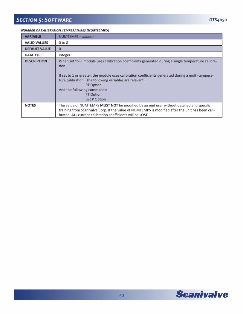
60
DTS4050Section 5: SoftwareNumber of Calibration Temperatures (NUMTEMPS)
VARIABLE NUMTEMPS <values>VALID VALUES 0 to 8DEFAULT VALUE 0DATA TYPE integerDESCRIPTION When set to 0, module uses calibration coefficients generated during a single temperature calibra-
tion.
If set to 1 or greater, the module uses calibration coefficients generated during a multi-tempera-ture calibration. The following variables are relevant: PT OptionAnd the following commands: PT Option List P Option
NOTES The value of NUMTEMPS MUST NOT be modified by an end user without detailed and specific training from Scanivalve Corp. If the value of NUMTEMPS is modified after the unit has been cali-brated, ALL current calibration coefficients will be LOST.

61
DTS4050 Section 5: Software
Precision Time Protocol Variables (LIST PTP)
PTP Enable (PTPEN)
VARIABLE PTPEN <value>VALID VALUES 0 or 1DEFAULT VALUE 0DATA TYPE integerDESCRIPTION Enables or disables the PTP engine.
0 – disabled 1 – enabled
Tune (TUNE)
VARIABLE TUNE <min filter depth> <clock gain> <integral limit> <median filter depth>VALID VALUES min filter - Not range checked
clock gain - Not range checkedintegral limit - Not range checkedmedian filter - Not range checked
DEFAULT VALUE min filter - 10clock gain - 0.5integral limit - 500000median filter - 5
DATA TYPE min filter - integerclock gain - floatintegral limit - integermedian filter - integer
DESCRIPTION These variables allow you to tune the PTP synch function.
Syslog Severity Level (SLL)
VARIABLE SLL <value>VALID VALUES 0 to 9DEFAULT VALUE 0DATA TYPE integerDESCRIPTION Sets the system log level:
0-Off1-Emergency2-Alert3-Critical4-Error5-Warning6-Notice7-Information8-Debug level 19-Debug level 2
Setting this value allows the any messages that occur with the severity level or above to be output to the device that last sent the command.
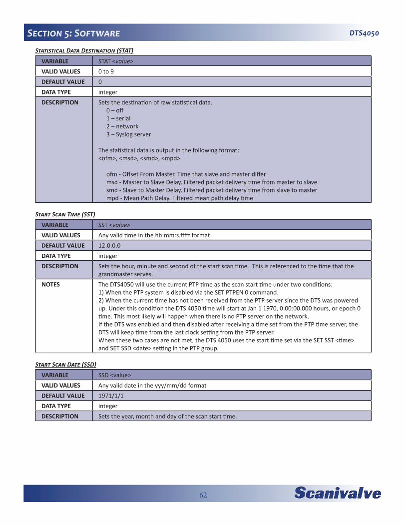
62
DTS4050Section 5: SoftwareStatistical Data Destination (STAT)
VARIABLE STAT <value>VALID VALUES 0 to 9DEFAULT VALUE 0DATA TYPE integerDESCRIPTION Sets the destination of raw statistical data.
0 – off1 – serial2 – network3 – Syslog server
The statistical data is output in the following format:<ofm>, <msd>, <smd>, <mpd>
ofm - Offset From Master. Time that slave and master differmsd - Master to Slave Delay. Filtered packet delivery time from master to slavesmd - Slave to Master Delay. Filtered packet delivery time from slave to mastermpd - Mean Path Delay. Filtered mean path delay time
Start Scan Time (SST)
VARIABLE SST <value>VALID VALUES Any valid time in the hh:mm:s.fffff formatDEFAULT VALUE 12:0:0.0DATA TYPE integerDESCRIPTION Sets the hour, minute and second of the start scan time. This is referenced to the time that the
grandmaster serves.NOTES The DTS4050 will use the current PTP time as the scan start time under two conditions:
1) When the PTP system is disabled via the SET PTPEN 0 command.2) When the current time has not been received from the PTP server since the DTS was powered up. Under this condition the DTS 4050 time will start at Jan 1 1970, 0:00:00.000 hours, or epoch 0 time. This most likely will happen when there is no PTP server on the network.If the DTS was enabled and then disabled after receiving a time set from the PTP time server, the DTS will keep time from the last clock setting from the PTP server.When these two cases are not met, the DTS 4050 uses the start time set via the SET SST <time> and SET SSD <date> setting in the PTP group.
Start Scan Date (SSD)
VARIABLE SSD <value>VALID VALUES Any valid date in the yyy/mm/dd formatDEFAULT VALUE 1971/1/1DATA TYPE integerDESCRIPTION Sets the year, month and day of the scan start time.
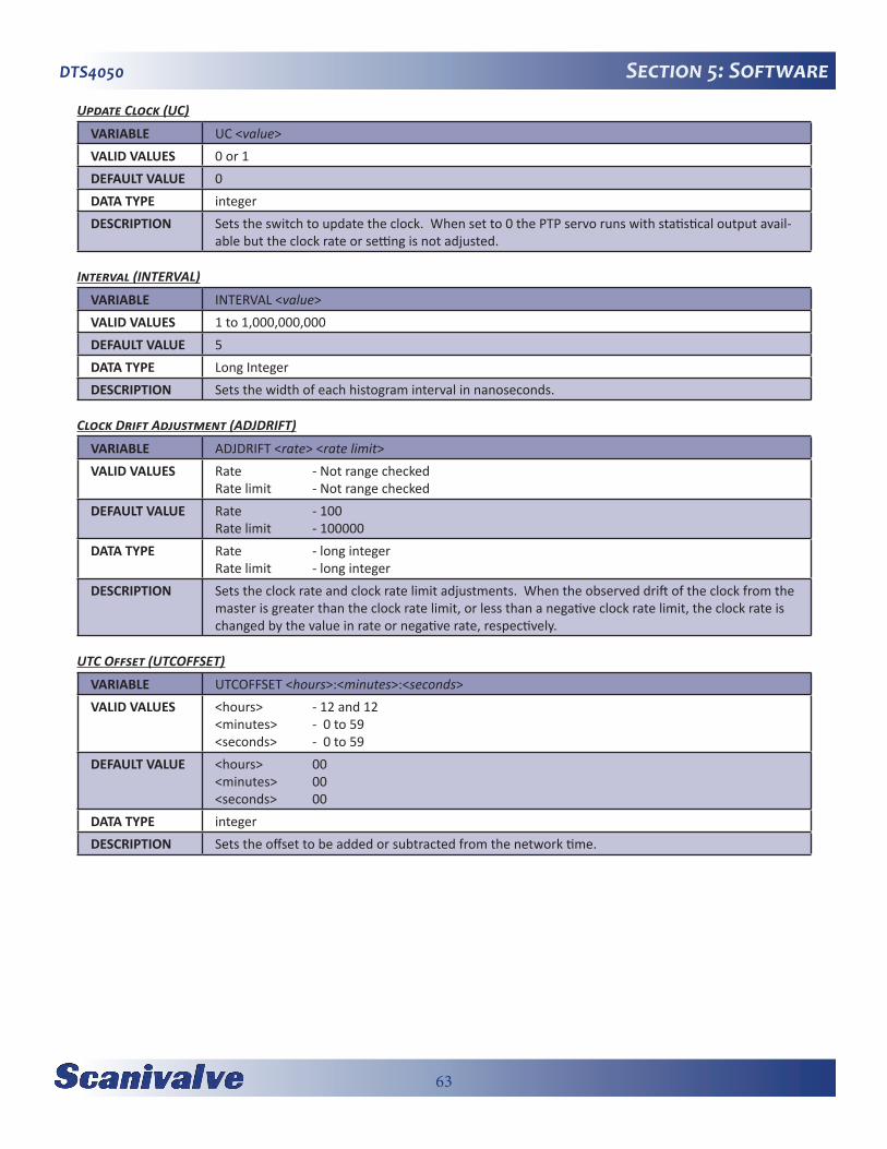
63
DTS4050 Section 5: Software
Update Clock (UC)
VARIABLE UC <value>VALID VALUES 0 or 1DEFAULT VALUE 0DATA TYPE integerDESCRIPTION Sets the switch to update the clock. When set to 0 the PTP servo runs with statistical output avail-
able but the clock rate or setting is not adjusted.
Interval (INTERVAL)
VARIABLE INTERVAL <value>VALID VALUES 1 to 1,000,000,000DEFAULT VALUE 5DATA TYPE Long IntegerDESCRIPTION Sets the width of each histogram interval in nanoseconds.
Clock Drift Adjustment (ADJDRIFT)
VARIABLE ADJDRIFT <rate> <rate limit> VALID VALUES Rate - Not range checked
Rate limit - Not range checkedDEFAULT VALUE Rate - 100
Rate limit - 100000DATA TYPE Rate - long integer
Rate limit - long integerDESCRIPTION Sets the clock rate and clock rate limit adjustments. When the observed drift of the clock from the
master is greater than the clock rate limit, or less than a negative clock rate limit, the clock rate is changed by the value in rate or negative rate, respectively.
UTC Offset (UTCOFFSET)
VARIABLE UTCOFFSET <hours>:<minutes>:<seconds>VALID VALUES <hours> - 12 and 12
<minutes> - 0 to 59<seconds> - 0 to 59
DEFAULT VALUE <hours> 00<minutes> 00<seconds> 00
DATA TYPE integerDESCRIPTION Sets the offset to be added or subtracted from the network time.
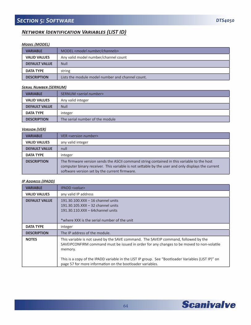
64
DTS4050Section 5: Software
Network Identification Variables (LIST ID)
Model (MODEL)
VARIABLE MODEL <model number/channels>VALID VALUES Any valid model number/channel count DEFAULT VALUE Null
DATA TYPE stringDESCRIPTION Lists the module model number and channel count.
Serial Number (SERNUM)
VARIABLE SERNUM <serial number>VALID VALUES Any valid integerDEFAULT VALUE NullDATA TYPE integerDESCRIPTION The serial number of the module
Version (VER)
VARIABLE VER <version number>VALID VALUES any valid integerDEFAULT VALUE nullDATA TYPE integerDESCRIPTION The firmware version sends the ASCII command string contained in this variable to the host
computer binary receiver. This variable is not settable by the user and only displays the current software version set by the current firmware.
IP Address (IPADD)
VARIABLE IPADD <value>VALID VALUES any valid IP addressDEFAULT VALUE 191.30.100.XXX – 16 channel units
191.30.105.XXX – 32 channel units191.30.110.XXX – 64channel units
*where XXX is the serial number of the unitDATA TYPE integerDESCRIPTION The IP address of the module.NOTES This variable is not saved by the SAVE command. The SAVEIP command, followed by the
SAVEIPCONFIRM command must be issued in order for any changes to be moved to non-volatile memory.
This is a copy of the IPADD variable in the LIST IP group. See “Bootloader Variables (LIST IP)” on page 57 for more information on the bootloader variables.
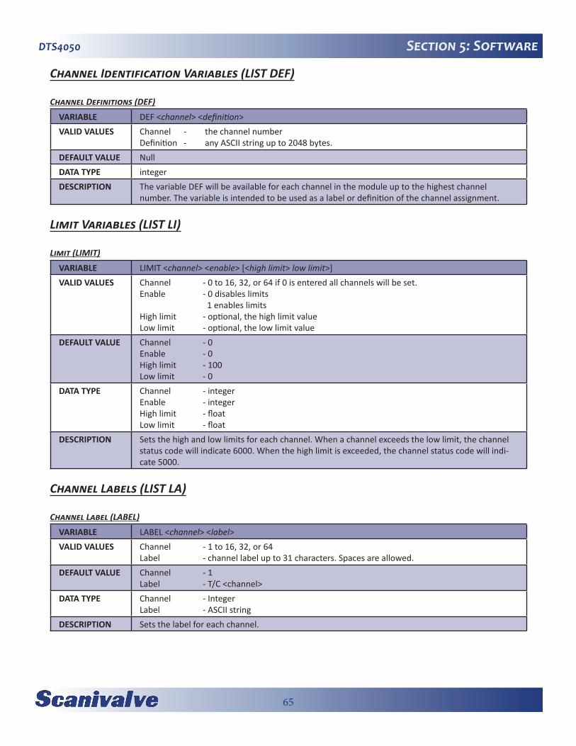
65
DTS4050 Section 5: Software
Channel Identification Variables (LIST DEF)
Channel Definitions (DEF)
VARIABLE DEF <channel> <definition> VALID VALUES Channel - the channel number
Definition - any ASCII string up to 2048 bytes.DEFAULT VALUE NullDATA TYPE integerDESCRIPTION The variable DEF will be available for each channel in the module up to the highest channel
number. The variable is intended to be used as a label or definition of the channel assignment.
Limit Variables (LIST LI)
Limit (LIMIT)
VARIABLE LIMIT <channel> <enable> [<high limit> low limit>]VALID VALUES Channel - 0 to 16, 32, or 64 if 0 is entered all channels will be set.
Enable - 0 disables limits 1 enables limitsHigh limit - optional, the high limit valueLow limit - optional, the low limit value
DEFAULT VALUE Channel - 0Enable - 0High limit - 100Low limit - 0
DATA TYPE Channel - integerEnable - integerHigh limit - floatLow limit - float
DESCRIPTION Sets the high and low limits for each channel. When a channel exceeds the low limit, the channel status code will indicate 6000. When the high limit is exceeded, the channel status code will indi-cate 5000.
Channel Labels (LIST LA)
Channel Label (LABEL)
VARIABLE LABEL <channel> <label>VALID VALUES Channel - 1 to 16, 32, or 64
Label - channel label up to 31 characters. Spaces are allowed.DEFAULT VALUE Channel - 1
Label - T/C <channel>DATA TYPE Channel - Integer
Label - ASCII stringDESCRIPTION Sets the label for each channel.

66
DTS4050Section 5: Software
Thermocouple Variables (LIST T)
Thermocouple Type (TYPE)
VARIABLE TYPE <channel> <type> <shield connect>VALID VALUES channel - the channel number, 0 through 16, 32 or 64
type - thermocouple typeshield connect - 0 or 1
DEFAULT VALUE channel - 0type - E, J, K, N, R, S, Tshield connect - 0
DATA TYPE channel - integertype - charshield connect - integer
DESCRIPTION Determines the thermocouple conversion for each channel. Conversion tables for any thermo-couple type can be loaded into the DTS4050’s file system. The only limitation is the DTS’s -15mV to 70mV calibrated range. If the channel is entered as 0, all 16 channels will be set to the ther-mocouple type specified. The shield connection switch should be set based on the method used to ground or shield the thermocouple. If shield connect is set to 0, the switch will be open. The default setting is 1 or closed. Refer to “Thermocouple Grounding Scenarios” on page 23 for more information.

67
DTS4050 Section 5: Software
RTD Correction Variables (LIST RPC)
RTD Correction (RPC)
VARIABLE RPC <board> <index> <volts applied> <counts applied>VALID VALUES Board - RTD board number; 1, 2, 3or 4
Index - 0 to 7Volts Applied - any valid numberCounts Applied - any valid number
DEFAULT VALUE Channel - 1Index - 0Volts Applied - 0Counts Applied - 0
DATA TYPE Channel - IntegerIndex - IntegerVolts Applied - floatCounts Applied - Integer
DESCRIPTION This is the list of setpoints used to calibrate the RTD=s. Each RTD pair is corrected by the same set-points. Each module type has one (1) RTD A/D and consequently one (1) channel for each pair of RTD=s. A 16 channel module has 1 channel, a 32 channel module has 2 channels and a 64 channel module has 4 channels.
NOTES EXAMPLE:The List RP command is used to view these variables. The variables are set to the following before the initial factory calibration: SET RPC 1 0 0.095000 1287022 SET RPC 1 1 0.115000 1557974 SET RPC 1 2 0.131000 1774736
NOTE: The values shown here are values for an ideal RTD channel. The actual calibration setpoints may be different.

68
DTS4050Section 5: Software
RTD Conversion Volts to Ohms (LIST RTD)
RTD 1 (RTD 1)
VARIABLE RTD 1 <R0> <A> <B>VALID VALUES any real numberDEFAULT VALUE R0 - 100.00000
A - 3.908E-03B - (-)5.775E-07
DATA TYPE floatDESCRIPTION The conversion factors for RTD 1 to convert ohms to millivolts for temperature conversion. The
actual values are provided by the manufacturer. The values for A and B must be entered as expo-nents.
RTD 2 (RTD 2)
VARIABLE RTD 2 <R0> <A> <B>VALID VALUES any real numberDEFAULT VALUE R0 - 100.00000
A - 3.908E-03B - (-)5.775E-07
DATA TYPE floatDESCRIPTION The conversion factors for RTD 2 to convert ohms to millivolts for temperature conversion. The
actual values are provided by the manufacturer. The values for A and B must be entered as expo-nents.
RTD 3 (RTD 3)
VARIABLE RTD 3 <R0> <A> <B> (32 and 64 channel version only)VALID VALUES any real numberDEFAULT VALUE R0 - 100.00000
A - 3.908E-03B - (-)5.775E-07
DATA TYPE floatDESCRIPTION The conversion factors for RTD 3 to convert ohms to millivolts for temperature conversion. The
actual values are provided by the manufacturer. The values for A and B must be entered as expo-nents.
RTD 4 (RTD 4)
VARIABLE RTD 4 <R0> <A> <B> (32 and 64 channel version only)VALID VALUES any real numberDEFAULT VALUE R0 - 100.00000
A - 3.908E-03B - (-)5.775E-07
DATA TYPE floatDESCRIPTION The conversion factors for RTD 4 to convert ohms to millivolts for temperature conversion. The
actual values are provided by the manufacturer. The values for A and B must be entered as expo-nents.
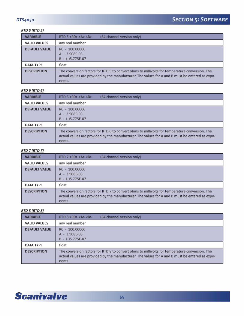
69
DTS4050 Section 5: Software
RTD 5 (RTD 5)
VARIABLE RTD 5 <R0> <A> <B> (64 channel version only)VALID VALUES any real numberDEFAULT VALUE R0 - 100.00000
A - 3.908E-03B - (-)5.775E-07
DATA TYPE floatDESCRIPTION The conversion factors for RTD 5 to convert ohms to millivolts for temperature conversion. The
actual values are provided by the manufacturer. The values for A and B must be entered as expo-nents.
RTD 6 (RTD 6)
VARIABLE RTD 6 <R0> <A> <B> (64 channel version only)VALID VALUES any real numberDEFAULT VALUE R0 - 100.00000
A - 3.908E-03B - (-)5.775E-07
DATA TYPE floatDESCRIPTION The conversion factors for RTD 6 to convert ohms to millivolts for temperature conversion. The
actual values are provided by the manufacturer. The values for A and B must be entered as expo-nents.
RTD 7 (RTD 7)
VARIABLE RTD 7 <R0> <A> <B> (64 channel version only)VALID VALUES any real numberDEFAULT VALUE R0 - 100.00000
A - 3.908E-03B - (-)5.775E-07
DATA TYPE floatDESCRIPTION The conversion factors for RTD 7 to convert ohms to millivolts for temperature conversion. The
actual values are provided by the manufacturer. The values for A and B must be entered as expo-nents.
RTD 8 (RTD 8)
VARIABLE RTD 8 <R0> <A> <B> (64 channel version only)VALID VALUES any real numberDEFAULT VALUE R0 - 100.00000
A - 3.908E-03B - (-)5.775E-07
DATA TYPE floatDESCRIPTION The conversion factors for RTD 8 to convert ohms to millivolts for temperature conversion. The
actual values are provided by the manufacturer. The values for A and B must be entered as expo-nents.
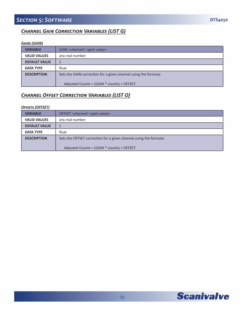
70
DTS4050Section 5: Software
Channel Gain Correction Variables (LIST G)
Gains (GAIN)
VARIABLE GAIN <channel> <gain value>VALID VALUES any real number DEFAULT VALUE 1DATA TYPE floatDESCRIPTION Sets the GAIN correction for a given channel using the formula:
Adjusted Counts = (GAIN * counts) + OFFSET.
Channel Offset Correction Variables (LIST O)
Offsets (OFFSET)
VARIABLE OFFSET <channel> <gain value>VALID VALUES any real number DEFAULT VALUE 1DATA TYPE floatDESCRIPTION Sets the OFFSET correction for a given channel using the formula:
Adjusted Counts = (GAIN * counts) + OFFSET.
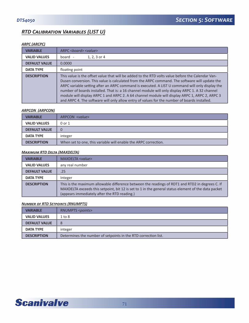
71
DTS4050 Section 5: Software
RTD Calibration Variables (LIST U)
ARPC (ARCPC)
VARIABLE ARPC <board> <value>VALID VALUES board - 1, 2, 3 or 4DEFAULT VALUE 0.0000DATA TYPE floating pointDESCRIPTION This value is the offset value that will be added to the RTD volts value before the Calendar Van-
Dusen conversion. This value is calculated from the ARPC command. The software will update the ARPC variable setting after an ARPC command is executed. A LIST U command will only display the number of boards installed. That is: a 16 channel module will only display ARPC 1. A 32 channel module will display ARPC 1 and ARPC 2. A 64 channel module will display ARPC 1, ARPC 2, ARPC 3 and ARPC 4. The software will only allow entry of values for the number of boards installed.
ARPCON (ARPCON)
VARIABLE ARPCON <value>VALID VALUES 0 or 1 DEFAULT VALUE 0DATA TYPE integerDESCRIPTION When set to one, this variable will enable the ARPC correction.
Maximum RTD Delta (MAXDELTA)
VARIABLE MAXDELTA <value>VALID VALUES any real numberDEFAULT VALUE .25DATA TYPE IntegerDESCRIPTION This is the maximum allowable difference between the readings of RDT1 and RTD2 in degrees C. If
MAXDELTA exceeds this setpoint, bit 12 is set to 1 in the general status element of the data packet (appears immediately after the RTD reading.)
Number of RTD Setpoints (RNUMPTS)
VARIABLE RNUMPTS <points>VALID VALUES 1 to 8DEFAULT VALUE 8DATA TYPE integerDESCRIPTION Determines the number of setpoints in the RTD correction list.
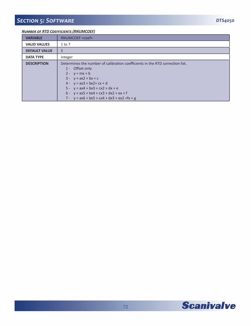
72
DTS4050Section 5: SoftwareNumber of RTD Coefficients (RNUMCOEF)
VARIABLE RNUMCOEF <coef>VALID VALUES 1 to 7DEFAULT VALUE 5DATA TYPE integerDESCRIPTION Determines the number of calibration coefficients in the RTD correction list.
1 - Offset only2 - y = mx + b 3 - y = ax2 + bx + c 4 - y = ax3 + bx2+ cx + d5 - y = ax4 + bx3 + cx2 + dx + e6 - y = ax5 + bx4 + cx3 + dx2 + ex + f7 - y = ax6 + bx5 + cx4 + dx3 + ex2 +fx + g
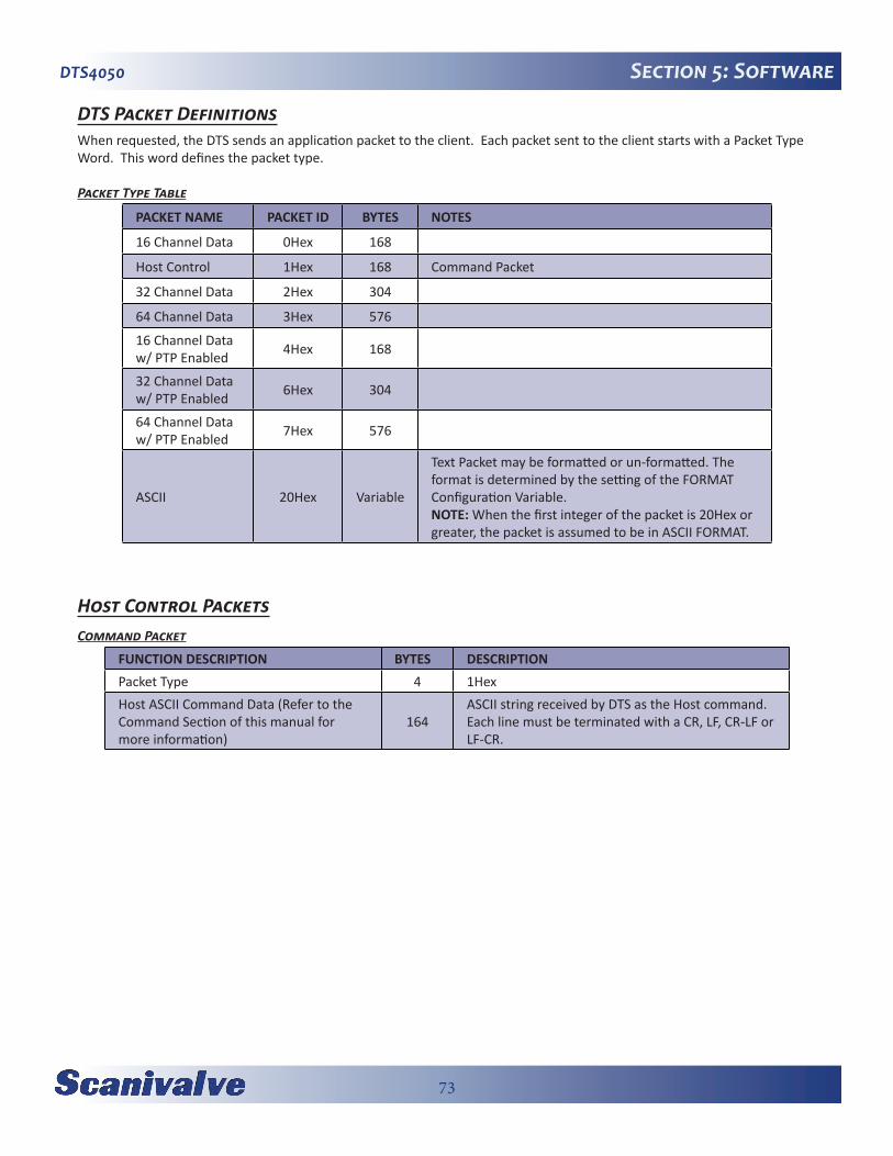
73
DTS4050 Section 5: Software
DTS Packet DefinitionsWhen requested, the DTS sends an application packet to the client. Each packet sent to the client starts with a Packet Type Word. This word defines the packet type.
Packet Type Table
PACKET NAME PACKET ID BYTES NOTES
16 Channel Data 0Hex 168
Host Control 1Hex 168 Command Packet
32 Channel Data 2Hex 304
64 Channel Data 3Hex 576
16 Channel Data w/ PTP Enabled 4Hex 168
32 Channel Data w/ PTP Enabled 6Hex 304
64 Channel Data w/ PTP Enabled 7Hex 576
ASCII 20Hex Variable
Text Packet may be formatted or un-formatted. The format is determined by the setting of the FORMAT Configuration Variable.NOTE: When the first integer of the packet is 20Hex or greater, the packet is assumed to be in ASCII FORMAT.
Host Control PacketsCommand Packet
FUNCTION DESCRIPTION BYTES DESCRIPTION Packet Type 4 1HexHost ASCII Command Data (Refer to the Command Section of this manual for more information)
164 ASCII string received by DTS as the Host command.Each line must be terminated with a CR, LF, CR-LF or LF-CR.
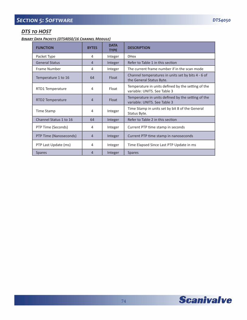
74
DTS4050Section 5: Software
DTS to HOSTBinary Data Packets (DTS4050/16 Channel Module)
FUNCTION BYTES DATA TYPE DESCRIPTION
Packet Type 4 Integer 0HexGeneral Status 4 Integer Refer to Table 1 in this sectionFrame Number 4 Integer The current frame number if in the scan mode
Temperature 1 to 16 64 Float Channel temperatures in units set by bits 4 - 6 of the General Status Byte.
RTD1 Temperature 4 Float Temperature in units defined by the setting of the variable: UNITS. See Table 3
RTD2 Temperature 4 Float Temperature in units defined by the setting of the variable: UNITS. See Table 3
Time Stamp 4 Integer Time Stamp in units set by bit 8 of the General Status Byte.
Channel Status 1 to 16 64 Integer Refer to Table 2 in this section
PTP Time (Seconds) 4 Integer Current PTP time stamp in seconds
PTP Time (Nanoseconds) 4 Integer Current PTP time stamp in nanoseconds
PTP Last Update (ms) 4 Integer Time Elapsed Since Last PTP Update in ms
Spares 4 Integer Spares

75
DTS4050 Section 5: Software
Binary Data Packets (DTS4050/32 Channel Module
FUNCTION BYTES DATA TYPE DESCRIPTION
Packet Type 4 Integer 2HexGeneral Status 4 Integer Refer to Table 1 in this sectionFrame Number 4 Integer The current frame number if in the scan mode
Temperature 1 to 32 128 Float Channel temperatures in units set by bits 4 - 6 of the General Status Byte.
RTD1 Temperature 4 Float Temperature in units defined by the setting of the variable: UNITS. See Table 3
RTD2 Temperature 4 Float Temperature in units defined by the setting of the variable: UNITS. See Table 3
RTD3 Temperature 4 Float Temperature in units defined by the setting of the variable: UNITS. See Table 3.
RTD4 Temperature 4 Float Temperature in units defined by the setting of the variable: UNITS. See Table 3
Time Stamp 4 Integer Time Stamp in units set by bit 8 of the General Status Byte.
Channel Status 1 to 32 128 Integer Refer to Table 2 in this section
PTP Time (Seconds) 4 Integer Current PTP time stamp in seconds
PTP Time (Nanoseconds) 4 Integer Current PTP time stamp in nanoseconds
PTP Last Update (ms) 4 Integer Time Elapsed Since Last PTP Update in ms
Spares 4 Integer Spares
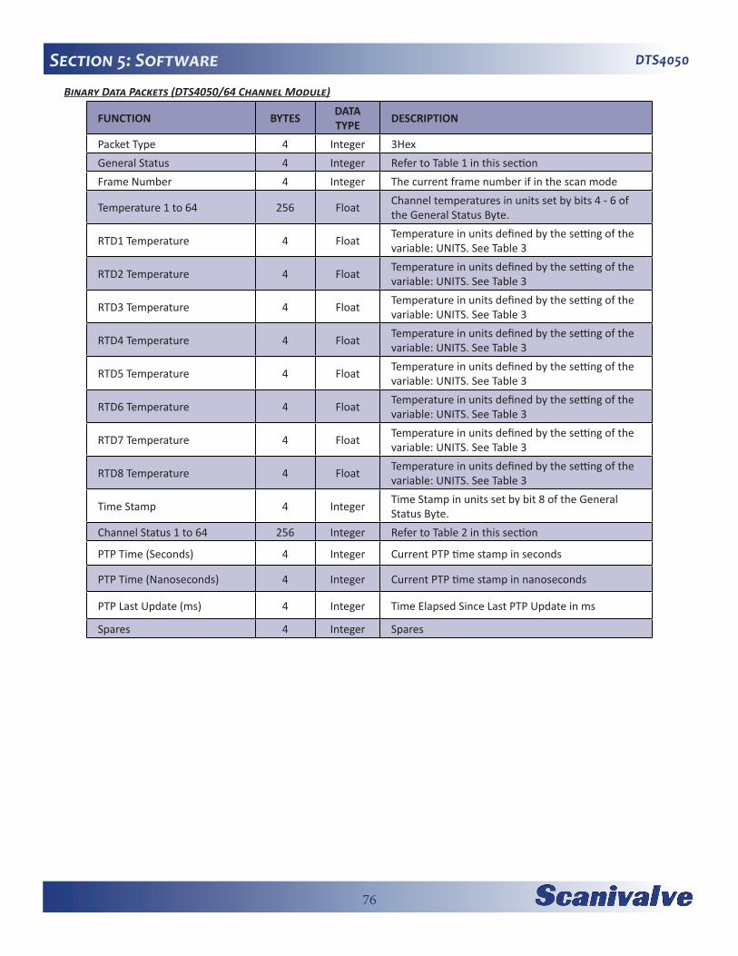
76
DTS4050Section 5: SoftwareBinary Data Packets (DTS4050/64 Channel Module)
FUNCTION BYTES DATA TYPE DESCRIPTION
Packet Type 4 Integer 3HexGeneral Status 4 Integer Refer to Table 1 in this sectionFrame Number 4 Integer The current frame number if in the scan mode
Temperature 1 to 64 256 Float Channel temperatures in units set by bits 4 - 6 of the General Status Byte.
RTD1 Temperature 4 Float Temperature in units defined by the setting of the variable: UNITS. See Table 3
RTD2 Temperature 4 Float Temperature in units defined by the setting of the variable: UNITS. See Table 3
RTD3 Temperature 4 Float Temperature in units defined by the setting of the variable: UNITS. See Table 3
RTD4 Temperature 4 Float Temperature in units defined by the setting of the variable: UNITS. See Table 3
RTD5 Temperature 4 Float Temperature in units defined by the setting of the variable: UNITS. See Table 3
RTD6 Temperature 4 Float Temperature in units defined by the setting of the variable: UNITS. See Table 3
RTD7 Temperature 4 Float Temperature in units defined by the setting of the variable: UNITS. See Table 3
RTD8 Temperature 4 Float Temperature in units defined by the setting of the variable: UNITS. See Table 3
Time Stamp 4 Integer Time Stamp in units set by bit 8 of the General Status Byte.
Channel Status 1 to 64 256 Integer Refer to Table 2 in this section
PTP Time (Seconds) 4 Integer Current PTP time stamp in seconds
PTP Time (Nanoseconds) 4 Integer Current PTP time stamp in nanoseconds
PTP Last Update (ms) 4 Integer Time Elapsed Since Last PTP Update in ms
Spares 4 Integer Spares
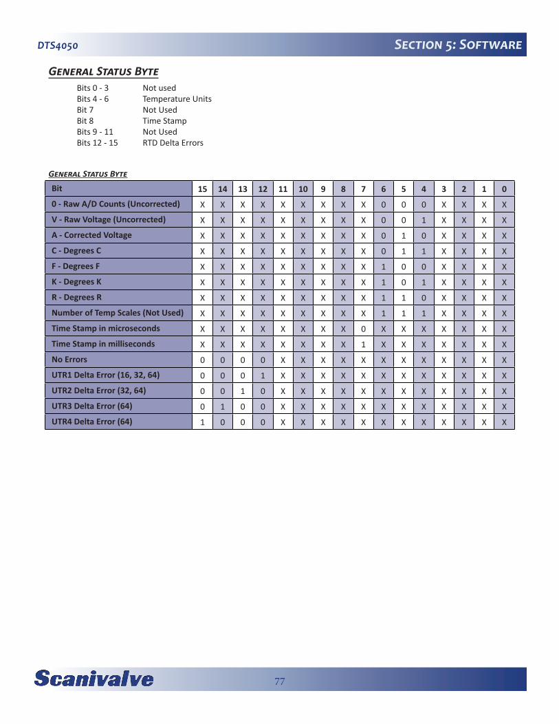
77
DTS4050 Section 5: Software
General Status Byte Bits 0 - 3 Not used Bits 4 - 6 Temperature Units Bit 7 Not Used Bit 8 Time Stamp Bits 9 - 11 Not Used Bits 12 - 15 RTD Delta Errors
General Status Byte
Bit 15 14 13 12 11 10 9 8 7 6 5 4 3 2 1 0
0 - Raw A/D Counts (Uncorrected) X X X X X X X X X 0 0 0 X X X X
V - Raw Voltage (Uncorrected) X X X X X X X X X 0 0 1 X X X X
A - Corrected Voltage X X X X X X X X X 0 1 0 X X X X
C - Degrees C X X X X X X X X X 0 1 1 X X X X
F - Degrees F X X X X X X X X X 1 0 0 X X X X
K - Degrees K X X X X X X X X X 1 0 1 X X X X
R - Degrees R X X X X X X X X X 1 1 0 X X X X
Number of Temp Scales (Not Used) X X X X X X X X X 1 1 1 X X X X
Time Stamp in microseconds X X X X X X X X 0 X X X X X X X
Time Stamp in milliseconds X X X X X X X X 1 X X X X X X X
No Errors 0 0 0 0 X X X X X X X X X X X X
UTR1 Delta Error (16, 32, 64) 0 0 0 1 X X X X X X X X X X X X
UTR2 Delta Error (32, 64) 0 0 1 0 X X X X X X X X X X X X
UTR3 Delta Error (64) 0 1 0 0 X X X X X X X X X X X X
UTR4 Delta Error (64) 1 0 0 0 X X X X X X X X X X X X
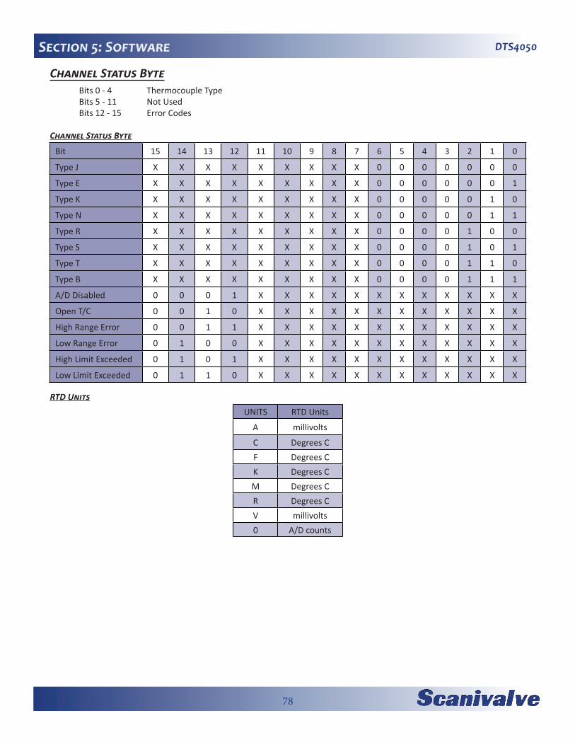
78
DTS4050Section 5: Software
Channel Status Byte Bits 0 - 4 Thermocouple Type Bits 5 - 11 Not Used Bits 12 - 15 Error Codes
Channel Status Byte
Bit 15 14 13 12 11 10 9 8 7 6 5 4 3 2 1 0
Type J X X X X X X X X X 0 0 0 0 0 0 0
Type E X X X X X X X X X 0 0 0 0 0 0 1
Type K X X X X X X X X X 0 0 0 0 0 1 0
Type N X X X X X X X X X 0 0 0 0 0 1 1
Type R X X X X X X X X X 0 0 0 0 1 0 0
Type S X X X X X X X X X 0 0 0 0 1 0 1
Type T X X X X X X X X X 0 0 0 0 1 1 0
Type B X X X X X X X X X 0 0 0 0 1 1 1
A/D Disabled 0 0 0 1 X X X X X X X X X X X X
Open T/C 0 0 1 0 X X X X X X X X X X X X
High Range Error 0 0 1 1 X X X X X X X X X X X X
Low Range Error 0 1 0 0 X X X X X X X X X X X X
High Limit Exceeded 0 1 0 1 X X X X X X X X X X X X
Low Limit Exceeded 0 1 1 0 X X X X X X X X X X X X
RTD Units
UNITS RTD Units
A millivolts
C Degrees CF Degrees CK Degrees CM Degrees CR Degrees CV millivolts0 A/D counts

79
DTS4050 Section 5: Software
ASCII Data Packet This packet will be transmitted when the host issues one of the following commands:
1) SCAN with BIN set to 02) LIST n3) ERROR 4) STATUS
ASCII data can be output in three different basic forms;1) Unformatted2) Unformatted with PTP data3) Formatted
FUNCTION DESCRIPTION BYTESDATA TYPE VALUE
ASCII Data (The first two bytes must NOT be 1Hex through 1FHex). Refer to the Com-mand Section of this manual for the proper Command return formats.
1 to 1492(Variable length)
StringUnique to Packet.Each line is terminated with a CR, LF, CR-LF, or LF-CR.
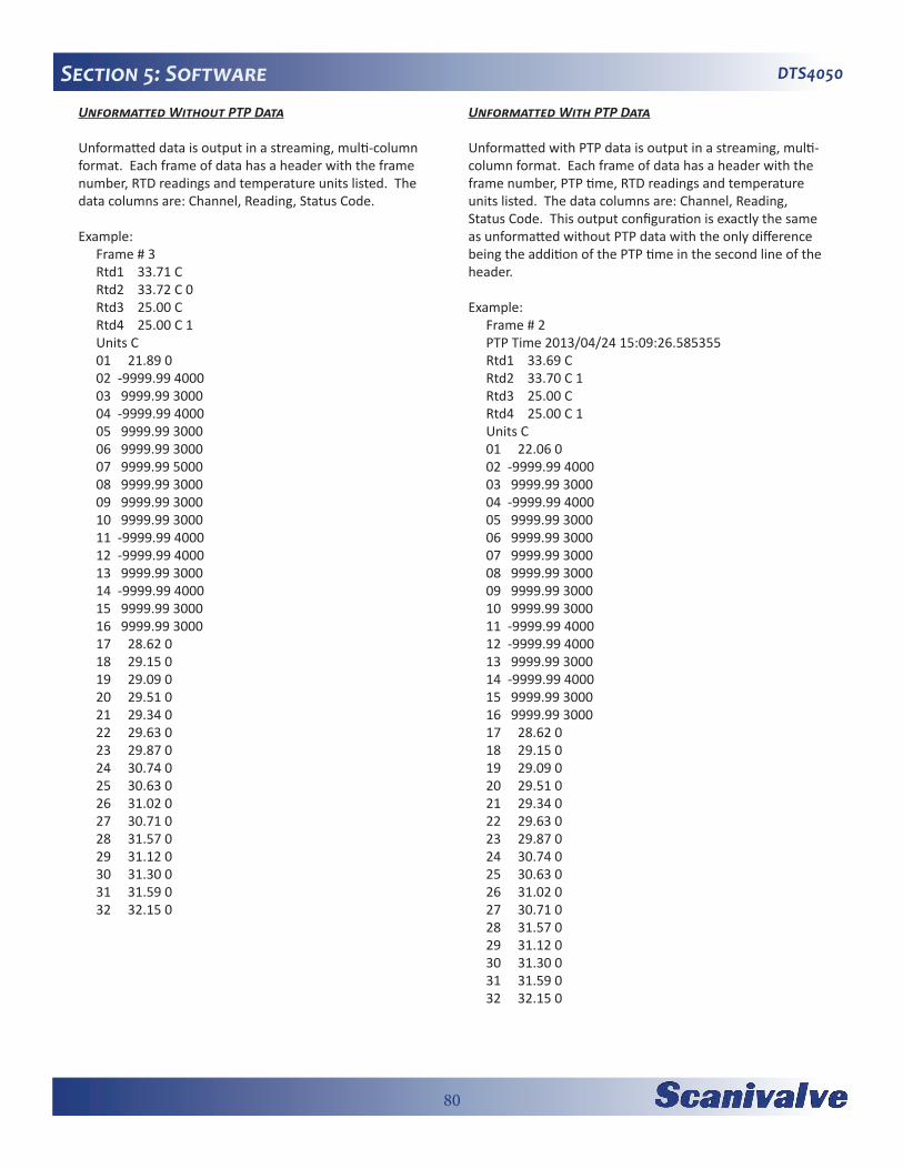
80
DTS4050Section 5: SoftwareUnformatted Without PTP Data
Unformatted data is output in a streaming, multi-column format. Each frame of data has a header with the frame number, RTD readings and temperature units listed. The data columns are: Channel, Reading, Status Code.
Example:Frame # 3Rtd1 33.71 CRtd2 33.72 C 0Rtd3 25.00 CRtd4 25.00 C 1Units C01 21.89 002 -9999.99 400003 9999.99 300004 -9999.99 400005 9999.99 300006 9999.99 300007 9999.99 500008 9999.99 300009 9999.99 300010 9999.99 300011 -9999.99 400012 -9999.99 400013 9999.99 300014 -9999.99 400015 9999.99 300016 9999.99 300017 28.62 018 29.15 019 29.09 020 29.51 021 29.34 022 29.63 023 29.87 024 30.74 025 30.63 026 31.02 027 30.71 028 31.57 029 31.12 030 31.30 031 31.59 032 32.15 0
Unformatted With PTP Data
Unformatted with PTP data is output in a streaming, multi-column format. Each frame of data has a header with the frame number, PTP time, RTD readings and temperature units listed. The data columns are: Channel, Reading, Status Code. This output configuration is exactly the same as unformatted without PTP data with the only difference being the addition of the PTP time in the second line of the header.
Example:Frame # 2PTP Time 2013/04/24 15:09:26.585355Rtd1 33.69 CRtd2 33.70 C 1Rtd3 25.00 CRtd4 25.00 C 1Units C01 22.06 002 -9999.99 400003 9999.99 300004 -9999.99 400005 9999.99 300006 9999.99 300007 9999.99 300008 9999.99 300009 9999.99 300010 9999.99 300011 -9999.99 400012 -9999.99 400013 9999.99 300014 -9999.99 400015 9999.99 300016 9999.99 300017 28.62 018 29.15 019 29.09 020 29.51 021 29.34 022 29.63 023 29.87 024 30.74 025 30.63 026 31.02 027 30.71 028 31.57 029 31.12 030 31.30 031 31.59 032 32.15 0

81
DTS4050 Section 5: Software
Formatted
If data formatting is enabled (variable SET FORMAT 1), the data is displayed in a block-style format. This configuration is preferred for manual viewing but is not desirable for data collection. PTP data is not available in formatted data.
Example:
Frame=0000000 Rtd1= 19.70 C Rtd2= 19.71 C Rtd3= 19.72 C Rtd4= 19.71 C Units=C 01= -9999.99 02= -9999.99 03= -9999.99 04= -9999.99 05= 9999.99 06= -9999.99 07= 9999.99 08= -9999.99 09= -9999.99 10= -9999.99 11= -9999.99 12= -9999.99 13= -9999.99 14= -9999.99 15= 9999.99 16= -9999.99 17= -9999.99 18= -9999.99 19= -9999.99 20= -9999.99 21= -9999.99 22= 9999.99 23= -9999.99 24= -9999.99 25= 9999.99 26= -9999.99 27= -9999.99 28= 9999.99 29= -9999.99 30= -9999.99 31= -9999.99 32= 9999.99
Network Protocols SupportedPhysical Layer : 10Base-T IEEE 802.3Link Layer: INTERNET Protocol (IP)Transport Layer: Transmission Control Protocol (TCP)User Datagram Protocol (UDP)

82
DTS4050Section 5: Software
[This page intentionally left blank]

83
DTS4050 Section 6: Maintenance
SECTION 6: MAINTENANCECalibrationAll DTS4050 modules are calibrated before they are shipped. The calibration performed at Scanivalve is traceable to NIST. Scanivalve recommends subsequent cali-brations at 6 month intervals in order to maintain accuracy. Calibrations may be performed at the Scanivalve factory or by a customer in the field. Customers who wish to perform their own calibrations can use Scanivalve’s free calibration software, TempCal. TempCal can be downloaded at no cost from the Scanivalve website at www.scanivalve.com.
The TempCal software calibrates the voltage A/Ds in the DTS4050 module. It can be operated in either automatic or manual mode depending on the voltage standard being used. In order to calibrate a DTS using TempCal, a calibra-tion harness is required. The calibration harness can be ordered from Scanivalve using the following part numbers:
21079-1 (for 16 channel DTS modules)21079-2 (for 32 channel DTS modules)21079-3 (for 64 channel DTS modules)
In addition to the calibration harness, a host computer run-ning Windows XP or Windows 7 and a DC voltage standard with a range of -10mV to +131mV and an accuracy of ±1.5μV or better is required. The procedure for performing a voltage calibration on a DTS using TempCal can be found in the TempCal software manual.
TempCal does not perform a recalibration of the RTDs. Calibration of the RTDs should be completed on a five year interval. Consult Scanivalve directly for a copy of the “full” calibration procedure including calibrating the RTDs. In order to perform a complete calibration, the following addi-tional equipment is required:
Digital Volt/Ohmmeter - ±10μV accuracy from 95 to 105mVdc
100 Ω standard resistor - accurate within ±0.001%Ice point referenceThermocouple simulator
A/D Calibration (ADCAL)The DTS4050 includes an internal A/D self-calibration function called “ADCAL.” This is automatically performed at powerup and whenever the PERIOD variable is changed however it is recommended that the ADCAL be performed periodically in certain situations. Scanivalve recommends that an ADCAL be performed after the module has warmed
up and reached a stable temperature. An ADCAL should also be performed if the DTS is subjected to an ambient temperature change of more than 5°C. Finally, if the DTS has been running continuously for more than a 1 week period, an ADCAL should be performed. For more informa-tion on the ADCAL, see “A/D Calibration” on page 27.
Internet Explorer Setup for FTPThe firmware and coefficient procedures that follow may not function correctly if Windows Internet Explorer is not set up correctly. A user should verify these settings before attempting these procedures.
1. Open Internet Explorer.2. Click on Tools3. Select Internet Options from the drop down menu.
The Internet Options window will open.
4. Click on the Advanced Tab.5. Scroll down to the Heading marked “Browsing”6. Make sure that the line “Enable FTP Folder View
(Outside of Internet Explorer)” is checked. If this is not enabled, Internet Explorer will block FTP file transfers.
7. Click OK to accept the settings.
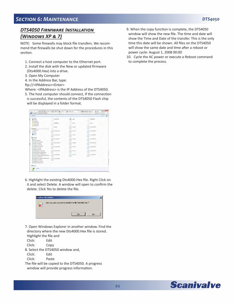
84
DTS4050Section 6: Maintenance
DTS4050 Firmware Installation (Windows XP & 7)NOTE: Some firewalls may block file transfers. We recom-mend that firewalls be shut down for the procedures in this section.
1. Connect a host computer to the Ethernet port.2. Install the disk with the New or updated firmware
(Dts4000.Hex) into a drive. 3. Open My Computer4. In the Address Bar, type:ftp://<IPAddress><Enter> Where: <IPAddress> is the IP Address of the DTS4050.5. The host computer should connect, If the connection
is successful, the contents of the DTS4050 Flash chip will be displayed in a folder format.
6. Highlight the existing Dts4000.Hex file. Right Click on it and select Delete. A window will open to confirm the delete. Click Yes to delete the file.
7. Open Windows Explorer in another window. Find the directory where the new Dts4000.Hex file is stored. Highlight the file and
Click: Edit Click: Copy8. Select the DTS4050 window and, Click: Edit Click: PasteThe file will be copied to the DTS4050. A progress
window will provide progress information.
9. When the copy function is complete, the DTS4050 window will show the new file. The time and date will show the Time and Date of the transfer. This is the only time this date will be shown. All files on the DTS4050 will show the same date and time after a reboot or power cycle: August 1, 2008 00:00
10. Cycle the AC power or execute a Reboot command to complete the process.

85
DTS4050 Section 6: Maintenance
Operating in Bootloader ModeIf the DTS4050 will not boot, or appears to have lost com-munications with a Host, the system may be operated in the Bootloader Mode. In this mode of operation, the appli-cation will not start. A list of commands that may be used in the bootloader mode can be found in “DSP Boot Loader” on page 18. All commands may be entered by the Ether-net or Configuration ports.
This mode may be set by switching Dip Switch 1 to the on position.
CAUTION! ESD PROTECTION REQUIRED. The proper use of grounded work surfaces and personal wrist straps are required when coming into contact with exposed circuits to prevent static discharge from damaging sensi-tive electronic components.
1. Switch the input power off, and remove the DTS4050 top insulating cover. In order to access the Dip Switches, the connector end cover must be removed. Removed the nine phillips screws shown and carefully pull the end cover off of the unit.
2. The dip switches are located on the front edge of the processor board. For reference purposes, OFF is towards the bottom of the DTS4050, and on is towards the top of the DTS4050 (towards the circuit board). Slide DIP switch #1 up to turn it on.
3. Re-apply power to the DTS4050. The application will not run, but the bootloader commands can be used to troubleshoot system problems.
4. The most common reason to enter the bootloader is to check or change the IP address of the unit. Once the unit has booted up in the bootloader, send the com-mand “LIST IP” The variable IPADD sets the device IP address. If desired, it can be modified and then saved with the SAVEIP command. Once the save has com-pleted, cycling the power on the unit will implement the new IP address.
5. When troubleshooting is complete, remove power and reset switch #1 to the off position (towards the bottom of the unit). Reinstall the top cover and re-apply power.

86
DTS4050Section 4: Hardware
Reformatting the DTS4050Should the file system on the DTS4050 become corrupted, the unit would have to be reformatted. This procedure will delete all data on the DTS4050. Before performing this operation, ensure that all files can be recovered. This can be done by copying the files off of the DTS before reformat-ting it, or by retrieving the files from the Resource Disk supplied with the unit.
1. Begin by powering the DTS unit down and con-figuring it to operate in bootloader mode (see “Operating in Bootloader Mode” on page 85).
2. Power the DTS4050 up and establish an Ethernet connection as normal. Because the DIP switches have been reconfigured, you will boot in the bootloader instead of the application. Verify the connection is good by sending the VER command. The DTS4050 should respond with the version of the bootloader (not the application!).
3. To format the SD card, send the command:
FDISK
Followed by:
FDISKCONFIRM
It will take about 5-10 seconds for the disk to com-pletely format.
4. When the DTS4050 was formatted, all information including the IP Address was lost. To reset a new IP address, send the command: SET IPADD xxx.xxx.xxx.xxx*(where xxx.xxx.xxx is the new IP address)
Verify the IP address is set properly by sending the LIST S command and checking the setting of the IPADD variable. If it is correct, save the new IP address by sending the command:
SAVEIP
Followed by:
SAVEIPCONFIRM
If the IP Address is not set at this point and the DTS4050 is powered down, the default IP address will be used. At this point, the flash memory has been formatted and the DTS4050’s IP address has been re-established.
5. Power the DTS4050 down. Remove the processor
board assembly and reconfigured the DIP switches for normal operation.
6. Power the DTS4050 back up. Establish and Ethernet connection to is using the IP address established in step 4 as normal. At this point, the DTS4050 will be operating completely on factory defaults with no calibration coefficients loaded. FTP to the unit using your preferred method and restore the application file (DTS4000.hex), factory coefficients and the CV.GPF (basic configuration file). All of the configuration files and the application file can be found on the DTS4050 Resource Disk supplied with the DTS4050. If there is not an archived copy of this file, each of the configuration variables can be reconfigured manually through the SET commands and then saved with the SAVE command.

87
DTS4050 Appendix
APPENDIXAppendix A: Thermocouple InformationThermocouple Basics When two dissimilar metals are joined together to form a closed loop, and if one junction is held at a different tem-perature from the other, an Electromotive Force(EMF) is generated. The amount of EMF generated is predictable based on the materials used and the temperature of the junction.
The EMF is generated by the wires, not the junction. A temperature gradient must exist before the EMF can be generated.
Three laws have been established that govern thermoelec-tric circuits.
Law of Homogeneous Materials: A thermoelectric current cannot be sustained in a
circuit of a single homogeneous material, however it varies in cross section, by the application of heat alone. Simply stated, two different materials are required for any thermocouple circuit. If current can be detected in a homogeneous wire when it is heated, this is evidence that the wire is in-homogeneous.
Law of Intermediate Materials: The algebraic sum of the thermoelectromotive forces
in a circuit composed of any number of dissimilar materials is zero if all of the circuit is at a uniform tem-perature. This law states that a third homogeneous material can be added to a circuit with no effect on the net EMF of the circuit as long as temperature of the junctions remain the same.
Law of Successive or Intermediate Temperature: If two dissimilar homogeneous materials produce a
thermal EMF of E1 when the junctions are at tempera-ture T1 and T2 , and a thermal EMF of E2 when the junctions are at T2 and T3, the EMF generated when the junctions are at T1 and T3 will be E1 + E2. This law states that a thermocouple calibrated for one reference temperature can be used with any other reference temperature with a correction. Also, extension wires having the same characteristics as those of the thermo-couple wires can be introduced to the circuit without affecting the circuit.
Thermocouple Circuits:A basic thermocouple circuit consists of two dissimilar homogenous materials extending from the measuring junc-tion to the reference junction.
When more than one thermocouple is to be measured, each thermocouple should be two continuous wires between the measuring and reference junctions. This is the most common circuit for thermoelectric testing.
Thermocouple Accuracy:Thermocouple accuracy can be defined as relative and absolute accuracy.
Relative Accuracy This is the ability of the system to repeat a given
measurement. This depends upon the quality of the sensors, the measuring system used and how the system is installed.
Absolute Accuracy This is the ability of the system to determine a standard
accepted value. This can be achieved by calibration relative accepted and recognized standards.
Thermocouple Calibration:Calibration will not change the characteristics of a ther-mocouple. It does validate the system and ensure proper readings by allowing corrections to be entered for each thermocouple in the system. Calibrations should conform to ISO 10012-1:1992.
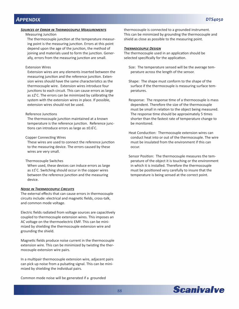
88
DTS4050AppendixSources of Error in Thermocouple Measurements
Measuring Junction The thermocouple junction at the temperature measur-
ing point is the measuring junction. Errors at this point depend upon the age of the junction, the method of joining and materials used to form the junction. Gener-ally, errors from the measuring junction are small.
Extension Wires Extension wires are any elements inserted between the
measuring junction and the reference junction. Exten-sion wires should have the same characteristics as the thermocouple wire. Extension wires introduce four junctions to each circuit. This can cause errors as large as ±2 ̊C. The errors can be minimized by calibrating the system with the extension wires in place. If possible, extension wires should not be used.
Reference Junctions The thermocouple junction maintained at a known
temperature is the reference junction. Reference junc-tions can introduce errors as large as ±0.6 ̊C.
Copper Connecting Wires These wires are used to connect the reference junction
to the measuring device. The errors caused by these wires are very small.
Thermocouple Switches When used, these devices can induce errors as large
as ±1 ̊C. Switching should occur in the copper wires between the reference junction and the measuring device.
Noise in Thermocouple Circuits The external effects that can cause errors in thermocouple circuits include: electrical and magnetic fields, cross-talk, and common mode voltage.
Electric fields radiated from voltage sources are capacitively coupled to thermocouple extension wires. This imposes an AC voltage on the thermoelectric EMF. This can be mini-mized by shielding the thermocouple extension wire and grounding the shield.
Magnetic fields produce noise current in the thermocouple extension wire. This can be minimized by twisting the ther-mocouple extension wire pairs.
In a multipair thermocouple extension wire, adjacent pairs can pick up noise from a pulsating signal. This can be mini-mized by shielding the individual pairs.
Common mode noise will be generated if a grounded
thermocouple is connected to a grounded instrument. This can be minimized by grounding the thermocouple and shield as close as possible to the measuring point.
Thermocouple DesignThe thermocouple used in an application should be selected specifically for the application.
Size: The temperature sensed will be the average tem-perature across the length of the sensor.
Shape: The shape must conform to the shape of the surface if the thermocouple is measuring surface tem-peratures.
Response: The response time of a thermocouple is mass dependent. Therefore the size of the thermocouple must be small in relation to the object being measured. The response time should be approximately 5 times shorter than the fastest rate of temperature change to be monitored.
Heat Conduction: Thermocouple extension wires can conduct heat into or out of the thermocouple. The wire must be insulated from the environment if this can occur.
Sensor Position: The thermocouple measures the tem-perature of the object it is touching or the environment in which it is installed. Therefore the thermocouple must be positioned very carefully to insure that the temperature is being sensed at the correct point.

89
DTS4050 Appendix
Thermocouple Types and DescriptionsThe DTS family of Temperature Scanners will accept inputs from Type E, J, K, N, R, S, and T Thermocouples. The accu-racy of the measurement will depend upon the type of thermocouple and the quality of the extension wire used for the measurement.
Type BPositive leg 70% platinum, 30% rhodiumNegative leg 94% platinum, 6% rhodiumRange 0 to 1800̊CUsable range 400 to 1704̊CNotes Easily contaminated and damaged
by reducing atmospheres. This thermocouple should be protected with a gas tight ceramic tube, a secondary tube of porcelain and a silicon carbide or metal outer tube.
Type E - Chromel ConstantanPositive leg 90% nickel, 10% chromiumNegative leg 43% nickel, 57% copperRange -270 to 1000 ̊CUsable range 0 to 900 ̊CNotes Highest EMF output per degree
of all recognized thermocouples. Has similar drift between 316 and 593 ̊C as a Type K thermocouple
Type J - Iron ConstantanPositive leg 100% ironNegative leg 43% nickel, 57% copperRange -210 to 1200 ̊CUsable range 0 to 816 ̊CNotes Not susceptible to aging from 371
to 538 ̊C. Very stable, should be used with a 96% pure MgO insulation and stainless steel sheath to prevent corrosion of the iron lead. Most commonly used ther-mocouple.
Type K - Chromel AlumelPositive leg 90% nickel, 10% chromiumNegative leg 95% nickel, 2% aluminum, 2%
manganese, 1% siliconRange -270 to 1372 ̊CUsable range -36 to 1260 ̊CNotes Not recommended from 316 to
593 ̊C because of aging that can cause drift rates of 2 ̊C in a few hours. Best used when corrosion may be a problem.
Type NPositive leg 14% chromium, 1.4% silicon,
84.6% nickelNegative leg 95.6% nickel, 4.4% siliconRange -270 to 1372 ̊CUsable range 0 to 1260 ̊CNotes Less aging from 316 to 593 ̊C
than a Type K thermocouple.
Type RPositive leg 87% platinum, 13% rhodiumNegative leg 100% platinumRange -50 to 1767 ̊CUsable range 0 to 1482 ̊CNotes Has a higher output than Type
S thermocouples. Easily contaminated. This thermo-couple should be protected by compacted mineral insulation and a metal outer sheath.
Type SPositive leg 90% platinum, 10% rhodiumNegative leg 100% platinumRange -50 to 1767 ̊CUsable range 0 to 1482 ̊CNotes Easily contaminated. This ther-
mocouple should be protected with a gas tight ceramic tube, a secondary tube of porcelain and a silicon car-bide or metal outer tube.
Type T - Copper ConstantanPositive leg Pure copperNegative leg 43% nickel, 57% copperRange -270 to 400 ̊CUsable range -262 to 350 ̊CNotes Good for low temperature and
cryogenic applications

90
DTS4050AppendixInternational Thermocouple and Extension Wire Color Codes
Country USA USA United Kingdom
United Kingdom Germany Japan Fance
Standard ANSIMC96.1 T/C
ANSI MC96.1
ExtensionBS 1843 BS 4937 DIN 43714 JIS C1610-
1981NFE C42-
323
B OverallB PositiveB Negative
-GrayGrayRed
- -GrayRedGray
GrayRedGray
-
E OverallE PositiveE Negative
BrownPurple
Red
PurplePurple
Red
BrownBrownBlue
BrownBrownBlue
BlackRed
Black
PurpleRed
White-
J OverallJ PositiveJ Negative
BrownWhite
Red
BlackWhite
Red
BlackYellowBlue
BlackBlackWhite
BlueRedBlue
YellowRed
White
BlackYellowBlack
K OverallK PositiveK Negative
BrownYellow
Red
YellowYellow
Red
RedBrownBlue
GreenGreenWhite
GreenRed
Green
BlueREd
White
YellowYellowPurple
N OverallN PositiveN Negative
BrownOrange
Red
OrangeOrange
Red- - - - -
R OverallR PositiveR Negative
-GreenBlackRed
GreenWhiteBlue
OrangeOrangeWhite
WhiteRed
White
BlackRed
White
GreenYellow Green
S OverallS PositiveS Negative
-BreenBlackRed
GreenWhiteBlue
OrangeOrangeWhite
WhiteRed
White
BlackRed
White
GreenYellowGreen
T OverallT PositiveT Negative
BrownBlueRed
BlueBlueRed
BlueWhiteBlue
BrownBrownWhite
BrownRed
Brown
BrownRed
White
BlueYellowBlue

91
DTS4050 Appendix
Appendix B - Software Change ListVersion 1.00 - Initial software release. (08/26/2013)
Version 1.01 - Updated to add MINRATE variable (4/21/14)
Version 1.02 - Changed the rate of the RTD A/D to 3x the T/C A/D rate. (6/11/14)
Version 1.03 - Added support for 32Mbit flash chip. Fixed the routing of the serial DIR command. Set SIM default to 0. Error checked for blank file in TYPE command. Remove value checking from QPKTS variable. Change default number of A/D board to 2. Move HW setting to top of LIST A. Added additional outputs to LIST A. Resolved a problem with the save SSN. Added the sequence number to the SAVE command. Remove the write to 4202 on the start up. Added SIM mode to background state function. (8/5/2014)
Version 1.04 - Resolved a bug with the IPO (Ice Point Offset) command that did not use both RTDs for the calculations. Reviewed coding to make channel numbering scheme uniform throughout, all numbering starts at 1. (Not Released)
Version 1.05 - Resolved a timing bug that would cause extremely noisy RTD readings approximately every 500 new scans. (12/9/2014)
Version 1.06 - Resolved a bug that would randomly configure the channel 49 A/D on 64 channel units incorrectly. Removed the initialization of the MODEL and SERNUM variables to ensure proper configuration during manufacture. (12/17/14)
Version 1.07 - Set counter 2 period to 0. Added support for TCP/IP binary data for legacy compatibility. Fixed problems with data destination selection. Added 10ms delay at the end of the FTP transfer to increase transfer reliability. (4/3/15)
Version 1.08 - Added support for binary data to be sent to the telnet port. CALAVG variable made active. (4/16/2015)
Version 1.09 - Resolved a bug in the RTD median filter that rendered it ineffective. (5/4/2015)

92
DTS4050
[This page intentionally left blank]

93
DTS4050
DTS4050 Hardware & Software ManualMay 4, 2015
1722 N. Madson St.Liberty Lake, WA 99019
Phone: 1-800-935-5151 1-509-891-9970
Fax: 1-509-891-9481