hardware-in-the-loop simulation and energy optimization of cardiac · pdf file ·...
TRANSCRIPT
Hardware-in-the-loop simulation and energy optimization of cardiacpacemakers
Chris Barker1, Marta Kwiatkowska2, Alexandru Mereacre2, Nicola Paoletti2 and Andrea Patane3
Abstract— Implantable cardiac pacemakers are medical de-vices that can monitor and correct abnormal heart rhythms.To provide the necessary safety assurance for pacemakersoftware, both testing and verification of the code, as wellas testing the entire pacemaker hardware in the loop, isnecessary. In this paper, we present a hardware testbed thatenables detailed hardware-in-the-loop simulation and energyoptimisation of pacemaker algorithms with respect to a heartmodel. Both the heart and the pacemaker models are encodedin Simulink/Stateflow™ and translated into executable code,with the pacemaker executed directly on the microcontroller.We evaluate the usefulness of the testbed by developing aparameter synthesis algorithm which optimises the timing pa-rameters based on power measurements acquired in real-time.The experiments performed on real measurements successfullydemonstrate that the testbed is capable of energy minimisationin real-time and obtains safe pacemaker timing parameters.
I. INTRODUCTION
Implantable cardiac pacemakers are medical devices thatuse electrical impulses in order to control the heart rate.The pacemaker is implanted in patients who have a slowheart beat (less than 60 BPM) or a block in the electricalconduction system. One of the main challenges is to ensurethat pacemakers are safe and consume the least amountof energy possible, since the latter reduces the frequencyof re-implantation, thus improving patients’ quality of life.Pacemaker safety is typically achieved through developingformal models of the embedded pacemaker software andanalysing their correctness using formal methods [4], [11],as well as requiring that the hardware components workwithin prescribed real-time bounds. Although pacemakerdevices include circuits to estimate the battery lifetime, theirparameters are typically set by the clinician based only onthe heart condition. Energy efficiency can be effectivelyaddressed by designing pacemaker algorithms that optimiseenergy consumption by regulating the pacing rate for agiven patient, taking into account the sensed physiologicalcondition. Design, verification and validation of pacemakeralgorithms is a demanding task, particularly in the presenceof multiple sensors.
In this paper, we develop a hardware testbed that supportshardware-in-the-loop simulation of model-based pacemakerdesigns, using hardware circuits that consume small amounts
∗This work is supported by the ERC AdG VERIWARE and ERC PoCVERIPACE
1University of Southampton, UK2Department of Computer Science, University of Oxford, UK3University of Catania, IT1,3Contributed to the work during an internship funded by the ERC PoC
Grant VERIPACE
Power Monitor
Pacemaker testbed
Sensing & Pacing
Heart Optimisation Algorithm
Measurements
New Parameter Values
Measurements
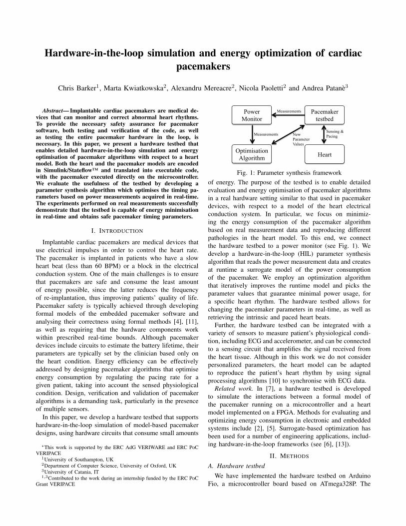
Fig. 1: Parameter synthesis frameworkof energy. The purpose of the testbed is to enable detailedevaluation and energy optimisation of pacemaker algorithmsin a real hardware setting similar to that used in pacemakerdevices, with respect to a model of the heart electricalconduction system. In particular, we focus on minimiz-ing the energy consumption of the pacemaker algorithmbased on real measurement data and reproducing differentpathologies in the heart model. To this end, we connectthe hardware testbed to a power monitor (see Fig. 1). Wedevelop a hardware-in-the-loop (HIL) parameter synthesisalgorithm that reads the power measurement data and createsat runtime a surrogate model of the power consumptionof the pacemaker. We employ an optimization algorithmthat iteratively improves the runtime model and picks theparameter values that guarantee minimal power usage, fora specific heart rhythm. The hardware testbed allows forchanging the pacemaker parameters in real-time, as well asretrieving the intrinsic and paced heart beats.
Further, the hardware testbed can be integrated with avariety of sensors to measure patient’s physiological condi-tion, including ECG and accelerometer, and can be connectedto a sensing circuit that amplifies the signal received fromthe heart tissue. Although in this work we do not considerpersonalized parameters, the heart model can be adaptedto reproduce the patient’s heart rhythm by using signalprocessing algorithms [10] to synchronise with ECG data.
Related work. In [7], a hardware testbed is developedto simulate the interactions between a formal model ofthe pacemaker running on a microcontroller and a heartmodel implemented on a FPGA. Methods for evaluating andoptimizing energy consumption in electronic and embeddedsystems include [2], [5]. Surrogate-based optimization hasbeen used for a number of engineering applications, includ-ing hardware-in-the-loop frameworks (see [6], [13]).
II. METHODS
A. Hardware testbed
We have implemented the hardware testbed on ArduinoFio, a microcontroller board based on ATmega328P. The

RA conductor
Ventricle
AV node
Atrium
RV conductor
Vget! Aget! AP? VP?
Heart model
AVI AP? AS?
VS?
VP!
LRI VP? AS?
VS? AP!
VRP Vget?
VP? VS!
PVARP VP? Aget?
VS?
AS!
URI VS?
VP?
AP! VP! Aget? Vget?
DDD Pacemaker testbed
Fig. 2: Architecture of the system
microcontroller runs at 3.3V and 8MHz. It has 2Kb ofSRAM, 14 digital input/output pins and 8 analog inputs. Itcan be connected to a Lithium Polymer battery and has inputsfor sensor circuits.
The system consists of two communicating modules andis depicted in Fig. 2. The pacemaker module implementsthe DDD functionality, that is, pacing and sensing of boththe atrium and the ventricle. It outputs two pacing signalsAP! and VP! for the atrium and ventricle, respectively, andreceives two heart signals, Aget? and Vget?, which denotethe presence of action potential in the atrium and ventricle.We use serial communication to create a hardware loopbetween the pacemaker and the heart. The heart module isimplemented as a Simulink™ model on a PC. It has a serialcommunication component for sending and receiving datafrom the hardware testbed and a Stateflow™ diagram thatimplements the electrical conduction system (ECS) of theheart. The heart module receives the AP? and VP? signalsfrom the pacemaker module and sends back the Aget! andVget! signals.
B. Heart and pacemaker Stateflow™ models
We consider the formal encoding of the heart model of[12] introduced in [1]. The Stateflow™ model consists of fivemain components, depicted in Fig. 2 (bottom). The atriumcomponent models the propagation of the action potential inthe atrium, the sino-atrial (SA) node (natural pacemaker ofthe heart) and the connection between the pacemaker atriallead and the heart. When the action potential reaches theatrial lead, the atrium component generates the Aget! signal.The atrium component propagates the so-called antegradeimpulse to the AV node through the RA conductor component.Intuitively, the RA conductor delays the action potentialcoming from the atrium. The AV node component actsas a filter for the atrium signals directed to the ventriclecomponent through the RV conductor, which applies furtherdelays. When the action potential reaches the ventricle lead,
Fig. 3: Power monitoring setup
a Vget! signal is generated. A ventricle beat (either intrinsicor paced) generates a retrograde impulse, which is conductedback to the atrium. When an antegrade and a retrogradesignal collide in the same conductor, a fusion beat occursand the two signals are annihilated. All five componentsof the heart model can be instantiated with parameterstailored to individual patients and can reproduce various heartarrhythmias, e.g. bradycardia (slow heart beat), tachycardia(fast heart beat) or AV block.
We have modelled the DDD pacemaker (Fig. 2 top)based on the Boston Scientific specification [3] and [8].The components are: atrio-ventricular interval (AVI), whichmaintains synchronisation between the atrium and ventricle;lower rate interval (LRI) and upper rate interval (URI), whichset safe bounds for the heart rate; post ventricular atrialrefractory period (PVARP) and ventricular refractory period(VRP), which are responsible for sensing, respectively, atrialand ventricular impulses. Every component has associated atiming parameter, which we discuss in Section III.
We use the Matlab™ code generation toolbox to translatethe pacemaker and heart models into C code. The pacemakercode is uploaded into the microcontroller, while the heartcode is executed on the PC. We enable serial communicationbetween the hardware testbed and the PC to allow sensingand pacing of atrial and ventricular signals.
C. Surrogate-based optimization
We describe the hardware-in-the-loop parameter synthe-sis framework for finding pacemaker parameters yieldingoptimal energy consumption values. In Fig. 3 we depictthe hardware set-up for power monitoring. We use theMonsoon™ power monitor device to power the pacemakerwith 3.7V and record the changes in the energy consumption.
The parameter synthesis algorithm generates randomly aset of parameter values and sends them to the hardwaretestbed. The hardware testbed and the heart model run for agiven amount of time and, at the end of the simulation, thepower monitor records the power measurements and sendsthem back to the synthesis algorithm. This process runsiteratively until the best (near-optimal) parameters are found.
The synthesis algorithm uses a surrogate-driven optimiza-tion (SDO) procedure [9]. SDO is a class of simulation-based optimization algorithms that derive a surrogate modelof the system under study in order to reduce the number ofsimulations of the original system. While the original systemcan be analytically intractable or expensive to simulate, the

surrogate model is fast and amenable to optimization. In ourcase, an evaluation of the objective function corresponds toa power measurement of the pacemaker device.
SDO algorithms alternate between two main phases: ob-tain approximate solutions x∗ by optimizing the surro-gate model; and evaluate the original model at x∗, usingthe obtained values to improve at runtime the accuracyof the surrogate. Our surrogate model is built followingthe Kriging method, which can be seen as a stochas-tic generalization of linear regression. Given n samplesx(1), x(2) . . . , x(n), and their respective objective functionvalues f
(x(1)
), f
(x(2)
). . . , f
(x(n)
), the method assumes
that they are drawn from a model of the form:
f(x(i)
)= ~g
(x(i)
)T
·~β + ε(x(i)
)i = 1, 2, . . . , n (1)
~g(x(i)
)T ·~β is called the regression part, where ~g(x(i)
)is the vector of basis functions and ~β is the vector ofunknown coefficients estimated through classical regressiontechniques. ε is normally distributed with zero mean andcorrelation dependent on a weighted Euclidean distance ofthe n samples. Such weights are the parameters of the surro-gate model, and are estimated by maximizing the likelihoodfunction.
The Kriging method is able to provide both an approx-imate value for f(x∗) and an estimate of the predictionstandard error. This property is exploited in the optimizationalgorithm, where the expected improvement of a point x∗
is computed assuming that its objective function value israndomly distributed according to Eq. 1. We remark thatthis method provides an approximate optimal solution anda well-behaved approximation of the energy consumptionfunction. Indeed, this is accurate in the region of interest(i.e. the optimal region of the input space), besides beingcheap to evaluate and analyse.
III. RESULTS
We synthesize the pacemaker parameters that minimizethe total electric current during 10 seconds of HIL simu-lation. Along with the optimal parameters, we also derivea surrogate statistical model (see Sect. II-C) that, giventhe pacemaker parameters, estimates at runtime the flowof the current. We consider two different heart conditions:bradycardia, i.e. slow heart rate, which we reproduce bydecreasing the firing rate of the SA node in the heartmodel; and a Wenckebach AV block, which causes the lossof ventricular beats due to the progressive prolongation ofthe AV conduction time. This is simulated by setting in theheart model a high threshold voltage of the AV node, whichincreases its depolarisation time.
We consider the following pacemaker parameters: TLRI(default value 1000 ms), which sets a lower bound on theheart rate; TAVI (default, 150 ms), which mimics the timeneeded for an atrial impulse to reach the ventricle; TURI(default, 500 ms), which sets an upper bound for the heartrate, i.e. the time before pacing the ventricle, after an atrialstimulus has occurred and TAVI elapsed; and TPVARP
(default, 250 ms), that is, the time during which atrial sensingis disabled after a ventricle event, so as to filter out atrialnoise. Since we aim at synthesizing parameters that alsoprovide a safe heart rhythm, we add a penalty to the objectivefunction for parameters yielding a heart rate outside the range[60, 120] BPM.
Figure 4 summarizes the results of energy optimization.In the AV block case (Fig. 4a), the minimum current isachieved at TLRI = 2047 ms and TAVI = 333 ms, evenif other regions with close power consumption values canbe observed. These values overestimate the default ones butare able to ensure a correct heart rhythm because, with anAV block, the heart possesses an adequate atrial frequency.This means that the sensed atrial impulses always precedethe time-out for atrial pacing. On the other hand, over-pacing occurs for low TLRI and TAVI, thus violating theheart safety property and yielding high objective functionvalues (red region in the bottom-left corner of Fig. 4a). Wealso evaluate the standard deviation (SD) associated withthe surrogate Kriging model (Fig. 4d). This analysis is ofcrucial importance because, ideally, pacemaker parametersthat yield low consumption with low variability are preferred.The variability tends to decrease close to sampled points,even if they can be surrounded by regions with high SD.This is the case for the obtained optimal solution. On theother hand, parameter regions with both low current flowand SD can be found approximately for TLRI ∈ [600, 1000]ms and TAVI < 1000 ms, or for TLRI < 1000 ms andTAVI ∈ [800, 1000] ms.
In the bradycardia case (Fig. 4b and 4e), the minimum to-tal current is 1630 A for TLRI = 1276 ms and TAVI = 471ms. In general, such parameter values are not recommendedfor patients with slow SA firing rate, since TLRI = 1276ms implies a pacing rate in the atrium of 47 BPM. Thus, thecombination of intrinsic heart impulses, albeit slow, with thepaced ones ensures the required safe heart rate. In this case,the region approximately given by TLRI ∈ [500, 1000] andTAVI ∈ [0, 500] yields both low current values and low SD.
In Fig. 4b and 4e, we estimate the total current withoutpenalizing unsafe heart parameters. The optimal parametervalues are TURI = 1899 ms and TPVARP = 1211 ms,but we observe that low current values can be achievedfor approximately TURI > 1300 ms. Clearly, high TURIvalues imply a lower pacing rate and thus lower energyconsumption, even if such parameters cannot provide anappropriate heart rate with an AV block condition. On theother hand, the value of TPVARP does not significantlyaffect the total current.
We report that the SDO algorithm is able to synthesizepacemaker parameters that improve the energy consumptionobtained with the default parameters. Moreover, it ensuresfast convergence to the optimal value, as shown in Fig. 5.
IV. CONCLUSION AND FUTURE WORK
We developed a hardware testbed to facilitate hardware-in-the-loop simulation and energy optimisation of implantablecardiac pacemakers. We implemented the pacemaker and

0 0.5 1 1.5 2 2.50
0.5
1
1.5
2
2.5
TLRI (s)
TA
VI (
s)
0
0.2
0.4
0.6
0.8
1
1.2
1.4
1.6
1.8
2x 10
5 A
(a) µ, AV block. Min current: 1618 A, atTLRI = 2047 ms and TAVI = 333 ms.Improvement: 1.64%.
0 0.5 1 1.5 2 2.50
0.5
1
1.5
2
2.5
TLRI (s)
TA
VI (
s)
0
0.2
0.4
0.6
0.8
1
1.2
1.4
1.6
1.8
2x 10
5
A
(b) µ, bradycardia. Min current: 1630 A, atTLRI = 1276 ms and TAVI = 471 ms.Improvement: 0.85%.
0 0.5 1 1.5 2 2.50
0.5
1
1.5
2
2.5
TURI (s)
TP
VA
RP
(s)
1.5
1.6
1.7
1.8
1.9
2
x 103
A
(c) µ. Min current: 1615 A, at TURI =1899 ms and TPVARP = 1211 ms.Improvement: 10.6%.
0 0.5 1 1.5 2 2.50
0.5
1
1.5
2
2.5
TLRI (s)
TA
VI (
s)
0
0.5
1
1.5
2
2.5
3
3.5
4
4.5
5x 10
4
A
(d) σ for plot (a).
0 0.5 1 1.5 2 2.50
0.5
1
1.5
2
2.5
TLRI (s)
TA
VI (
s)
0
0.5
1
1.5
2
2.5
3
3.5
4
4.5
5x 10
4
A
(e) σ for plot (b).
0 0.5 1 1.5 2 2.50
0.5
1
1.5
2
2.5
TURI (s)
TP
VA
RP
(s)
0
0.5
1
1.5
2
2.5
3
3.5
x 102
A
(f) σ for plot (c).
Fig. 4: Statistical estimation and optimization of the pacemaker total electrical current in 10 seconds simulation. Parametersare TLRI and TAVI for plots a,b,d,e; and TURI and TPVARP for plots c,f. Expected values are in top plots, standarddeviations in the bottom plots. Results are obtained through SDO, with 30 initial samples. Optimal parameters are indicatedwith a red cross. For each experiment, 150 unique points are sampled (white dots). In plots a,b,d,e, we add penalty of 105
A to points yielding a heart rate not in [60, 120] BPM. The relative improvement with respect to the expected total electricalcurrent for the default parameters is reported. Parameter ranges are [10, 2500] ms.
100 200 300 400 5001621
1622
1623
1624
1625
1626
1627
1628
1629
1630
1631
Num of samples
Tot
al c
urre
nt (
A)
Fig. 5: Best total current value at increasing number ofsamples. The experiment is as in Fig. 4b.
heart models as hybrid automata in Simulink/Stateflow,and encoded the pacemaker component into hardware. Wedemonstrated the usefulness of our testbed on the synthesisof safe and energy-efficient pacemaker parameters, by in-tegrating power measurements in the optimization loop andderiving predictive models of energy consumption. As futurework, we plan to generalize our approach to directly optimizepacemaker code.
REFERENCES
[1] B. Barbot, M. Kwiatkowska, A. Mereacre, and N. Paoletti. Estimationand verification of hybrid heart models for personalised medical andwearable devices. In CMSB. To appear, 2015.
[2] L. Benini and G. d. Micheli. System-level power optimization:techniques and tools. ACM Transactions on Design Automation ofElectronic Systems (TODAES), 5(2):115–192, 2000.
[3] Boston Scientific. Pacemaker system specification. 2007.[4] T. Chen, M. Diciolla, M. Kwiatkowska, and A. Mereacre. Quantitative
verification of implantable cardiac pacemakers over hybrid heartmodels. Information and Computation, 236:87–101, 2014.
[5] J. Flinn and M. Satyanarayanan. Powerscope: A tool for profilingthe energy usage of mobile applications. In Mobile ComputingSystems and Applications, 1999. Proceedings. WMCSA’99. SecondIEEE Workshop on, pages 2–10. IEEE, 1999.
[6] T. Hemker, H. Sakamoto, M. Stelzer, and O. von Stryk. Hardware-in-the-loop optimization of the walking speed of a humanoid robot. InProc. of CLAWAR, 2006.
[7] Z. Jiang, M. Pajic, and R. Mangharam. Cyber–physical modelingof implantable cardiac medical devices. Proceedings of the IEEE,100(1):122–137, 2012.
[8] Z. Jiang, M. Pajic, S. Moarref, R. Alur, and R. Mangharam. Modelingand verification of a dual chamber implantable pacemaker. In TACAS,volume 7214 of LNCS, pages 188–203. Springer, 2012.
[9] S. Koziel and X.-S. Yang. Computational optimization, methods andalgorithms, volume 356. Springer, 2011.
[10] M. Kwiatkowska, H. Lea-Banks, A. Mereacre, and N. Paoletti. Formalmodelling and validation of rate-adaptive pacemakers. In IEEEInternational Conference on Healthcare Informatics (ICHI), pages 23–32. IEEE, 2014.
[11] M. Kwiatkowska, A. Mereacre, and N. Paoletti. On quantitativesoftware quality assurance methodologies for cardiac pacemakers. InISoLA, LNCS, pages 365–384. Springer, 2014.
[12] J. Lian, D. Mussig, and V. Lang. Computer modeling of ventricularrhythm during atrial fibrillation and ventricular pacing. BiomedicalEngineering, IEEE Transactions on, 53(8):1512–1520, 2006.
[13] M. Mehari, E. De Poorter, I. Couckuyt, D. Deschrijver, J. Gerwen,T. Dhaene, and I. Moerman. Efficient multi-objective optimizationof wireless network problems on wireless testbeds. In Network andService Management (CNSM), 2014 10th International Conference on,pages 212–217. IEEE, 2014.