hardware manual - eagle 5 sas
TRANSCRIPT
DRAFT
910-0212-001 Revision D, December 2005
Tekelec EAGLE 5Signaling Application System
Hardware Manual
Table of Chapters
Table of Contents
List of Figures
List of Tables
Chapter 1. Introduction
Chapter 2. Systems Overview
Chapter 3. Hardware Descriptions — EAGLE/IP7 SG-Based Products
Chapter 4. Hardware Descriptions — OEM-Based Products
Chapter 5. Hardware Descriptions — Sentinel Products
Chapter 6. Site EngineeringEAGLE 5 SAS STP/IP7-Based Systems
Appendix A. Hardware Baselines
Appendix B. Sentinel 4-Port Monitor Appliques
Index

910-0212-001 Revision D, December 2005
Tekelec EAGLE®5Signaling Application System
Release 34.0
Hardware Manual910-0212-001 Revision D
December 2005

Copyright© 2005 TekelecAll Rights ReservedPrinted in U.S.A.
NoticeInformation in this documentation is subject to change without notice. Unauthorized use or copying of this documentation can result in civil or criminal penalties.
Any export of Tekelec products is subject to the export controls of the United States and the other countries where Tekelec has operations.
No part of this documentation may be reproduced or transmitted in any form or by any means, electronic or mechanical, including photocopying or recording, for any purpose without the express written permission of an authorized representative of Tekelec.
Other product names used herein are for identification purposes only, and may be trademarks of their respective companies.
TrademarksThe Tekelec logo, EAGLE, G-Flex, G-Port, IP7, IP7Edge, IP7 Secure Gateway, and TALI are registered trademarks of Tekelec, Inc. TekServer is a trademark of Tekelec, Inc. All other trademarks are the property of their respective owners.
PatentsThis product is covered by one or more of the following U.S. and foreign patents:
U.S. Patent Numbers:
5,008,929 5,953,404 6,167,129 6,324,183 6,327,350 6,606,379 6,639,981 6,647,113 6,662,017 6,735,441 6,745,0416,765,990 6,795,546 6,819,932 6,836,477 6,839,423 6,885,872 6,901,262 6,914,973 6,940,866 6,944,184 6,954,526 6,954,794 6,959,076 6,965,592 6,967,956 6,968,048 6,970,542 5,008,929 6,327,350 6,456,8456,765,990 6,901,262 6,967,956 6,968,048 6,970,542
Ordering InformationAdditional copies of this document can be ordered from:
Tekelec Network Signaling Division Attention: Central Logistics 5200 Paramount Parkway Morrisville, North Carolina, 27560
Or e-mail your request to [email protected].
910-0212-001 Revision D, December 2005 i
Table of Contents
Chapter 1. Introduction
Overview ...................................................................................... 1-3
Scope and Audience .................................................................... 1-4
NSD Systems ................................................................................ 1-5
EAGLE 5 SAS-Based Products ................................................... 1-6
EAGLE 5 SAS STP ................................................................. 1-6
IP7 Secure Gateway ............................................................... 1-6
Integrated Sentinel EAGLE 5 SAS STP Side ..................... 1-6
EOAP ...................................................................................... 1-7
OEM-Based Products .................................................................. 1-8
ASi 4000 Service Control Point ........................................... 1-8
Multi-Purpose Server ........................................................... 1-8
Operations Support System Applications Processor ....... 1-9
Sentinel Site Collector Frame with Flight Recorders ....... 1-9
Sentinel Server Frame ........................................................... 1-9
AXi Systems ......................................................................... 1-10
Manual Organization and Conventions .......................... 1-11
Related Publications ........................................................... 1-12
Customer Care Center .............................................................. 1-20
Problem – Critical ............................................................... 1-21
Problem – Major .................................................................. 1-21
Problem – Minor ................................................................. 1-22
Response ..................................................................................... 1-23
Emergency Response .......................................................... 1-23
Hardware Repair and Return .................................................. 1-24
Repair and Return Shipping Instructions ....................... 1-25
Repair and Return Shipping Instructions ....................... 1-27
Returning a Crate ................................................................ 1-28
Acronyms .................................................................................... 1-30
Chapter 2. Systems Overview
Introduction .................................................................................. 2-2
EAGLE 5 SAS and IP7 Secure Gateway Systems .................... 2-3
ii 910-0212-001 Revision D, December 2005
Table of Contents
Maintenance and Administration Subsystem ...................2-4
Communication Subsystem .................................................2-6
Application Subsystem .........................................................2-8
Timing Systems EAGLE 5 SAS STP/IP7 SG ....................2-15
High-Speed Master Timing ................................................2-18
Time Slot Counter Synchronization ..................................2-18
Embedded Operations Applications Processor .............2-18
GR-376 EOAP ......................................................................2-19
Integrated Sentinel .....................................................................2-20
Integrated Sentinel on the EAGLE 5 SAS STP Side ........2-22
Integrated Sentinel (ESP Frame Side) ...............................2-23
OEM-Based Products and Elements .......................................2-24
ASi 4000 SCP ........................................................................2-24
Multi-Platform Server (MPS) Systems ..............................2-24
Operations Support System Applications Processor .....2-25
AXi Systems ..........................................................................2-26
Non-Integrated Sentinel Solutions ....................................2-29
Components of OEM-Based Products ...................................2-30
OEM-Based Servers ...................................................................2-30
OEM-Based Network Elements .........................................2-30
OEM-Based Peripheral Components ................................2-31
Chapter 3. Hardware Descriptions — EAGLE/IP7 SG-Based Products
Introduction ..................................................................................3-3
Hardware Baselines ..............................................................3-3
Frames ............................................................................................3-3
Extension Frame ....................................................................3-9
Miscellaneous Frame ...........................................................3-14
OAP Frame ...........................................................................3-16
Control Frame ......................................................................3-18
Control Shelf .........................................................................3-18
Control Shelf Backplanes ....................................................3-21
Extension Shelf .....................................................................3-28
Extension Shelf Backplanes ................................................3-31
Modules .......................................................................................3-36
High Speed IMT Router .....................................................3-38
High-Speed Multiplexer Card ..........................................3-43
Table of Contents
910-0212-001 Revision D, December 2005 iii
Maintenance Disk and Alarm Card ................................. 3-46
Terminal Disk Module ....................................................... 3-50
Time Slot Counter Synchronization ................................. 3-55
Link Interface Modules ...................................................... 3-56
High-Capacity Application Processor-Based LIMs ....... 3-69
Database Communications Module and Database Service Module ........................................................................... 3-77
Database Service Module ................................................... 3-79
Double-Slot EDCM (IP7 SG 4.0) ........................................ 3-81
Single-Slot EDCM and EDCM-A (IP7 SG 5.0 and later) 3-83
Sentinel Transport Card ..................................................... 3-86
General Purpose Service Module ..................................... 3-87
Measurements Collection and Polling Module .............. 3-87
IPLIMx with Eight-Point Capability ................................ 3-87
Application Service Module .............................................. 3-88
Application Communications Module ............................ 3-94
Translation Service Module ............................................. 3-100
E1 Interface Backplane Module ...................................... 3-104
Configured as an E1 Card ................................................ 3-105
Configured as a Channel Card ........................................ 3-105
High-Capacity Multichannel Interface Module ........... 3-113
Air Management Card ..................................................... 3-119
Fuse and Alarm Panels ........................................................... 3-121
Fuse and Alarm Panel (P/N 870-0243-08) ..................... 3-127
Fuse and Alarm Panel (P/N 870-0243-09) ..................... 3-129
Fuse and Alarm Panel (P/N 870-1606-xx/870-2320-xx) ............................... 3-132
Fuse Assignments ............................................................. 3-138
Holdover Clock ........................................................................ 3-141
Maintenance Interface System Card .............................. 3-143
Critical Status Indicators Card ........................................ 3-145
Stratum-3 Card .................................................................. 3-145
TOCA and TOLA Cards .................................................. 3-146
MCA Card .......................................................................... 3-146
Operations Support System Application Processor (OAP) ................................................................ 3-148
Embedded OAP (EOAP) .................................................. 3-150
GR-376 EOAP .................................................................... 3-153
iv 910-0212-001 Revision D, December 2005
Table of Contents
Chapter 4. Hardware Descriptions — OEM-Based Products
OEM-Based Product Descriptions .............................................4-3
Frames .....................................................................................4-3
ASi 4000 SCP System .............................................................4-3
Multi-Purpose Server (MPS) System ................................4-11
AXi Systems ..........................................................................4-14
AXi System Types ................................................................4-17
OEM-Based Product Elements .................................................4-21
OEM-Based Servers ...................................................................4-21
ASi 4000 SCP Host Servers .................................................4-21
MPS Host Servers ................................................................4-25
AXi Servers ...........................................................................4-33
Extended Services Platform (ESP) Host Servers .............4-39
IP7 Front End (Optional) .....................................................4-44
Operations Support System Application Processor (OAP) Host Server (Optional) .................................................4-46
OEM-Based Networking Elements .........................................4-47
Ethernet Hubs ......................................................................4-47
Routers ..................................................................................4-48
Ethernet Switches ................................................................4-50
OEM-Based Peripheral Elements .............................................4-52
Breaker Panels ......................................................................4-52
Eight-Port Connector Box ...................................................4-55
Chapter 5. Hardware Descriptions — Sentinel Products
Sentinel Product Descriptions Overview .................................5-3
Sentinel Frames ......................................................................5-4
Site Collector Frames ............................................................5-6
Extended Services Platform (ESP) .......................................5-7
Integrated Sentinel (probe-less Solution) .................................5-8
Integrated Sentinel Hardware Overview ...........................5-9
ESP Subsystem ....................................................................5-15
ESP Subsystem Hardware Components ..........................5-15
Sentinel Probe Based Site Collector .........................................5-20
Site Collector Frames ..........................................................5-22
Site Collector Frame Hardware Components .................5-24
Sentinel Central Server Frames ................................................5-26

Table of Contents
910-0212-001 Revision D, December 2005 v
Sentinel Central Server Frame Hardware Components 5-28
Sentinel Central Server Frames Prior to Release 10.0 .... 5-30
Sentinel Central Server Frames Release 10.0 .................. 5-32
Sentinel Frames Common Components ................................ 5-34
Breaker Panels ..................................................................... 5-34
SAI/P Card .......................................................................... 5-36
8-Port Break-Out Box .......................................................... 5-36
Ethernet Interface Cards .................................................... 5-36
Ethernet Switches ................................................................ 5-37
Routers .................................................................................. 5-41
Hubs ...................................................................................... 5-42
Console/Alarm Servers ..................................................... 5-43
Chapter 6. Site EngineeringEAGLE 5 SAS STP/IP7-Based Systems
Safety and Cautionary Information .......................................... 6-2
Introduction .................................................................................. 6-2
Location ......................................................................................... 6-2
Space Requirements .............................................................. 6-2
Lighting .................................................................................. 6-3
Building Requirements ........................................................ 6-3
Heating Ventilation and Air Condition Requirements ... 6-4
Power Requirements ............................................................ 6-8
Populating the System ................................................................ 6-8
Link Interface Module (LIM) Requirements ..................... 6-8
Cards Type Requirements for SCCP Application with Group Ticket Voucher (TVG) .................................................... 6-9
Database Communications Module (DCM) and Double-Slot Enhanced DCM (EDCM) ....................... 6-10
Cabling DCM and Double-Slot EDCM Cards ................ 6-11
Single-Slot EDCM and EDCM-A (IP7 SG 5.0 ; EAGLE 5 SAS STP 28.1) ......................................................................... 6-13
Application Services Module Requirements .................. 6-13
Application Communications Module Requirements .. 6-14
OAP and Embedded OAP ................................................. 6-14
Appendix A. Hardware Baselines
Baseline Tables ............................................................................ A-1
EAGLE Releases 25.0 Through 26.05 ................................ A-2

vi 910-0212-001 Revision D, December 2005
Table of Contents
EAGLE Releases 26.1 Through 29.1 .................................. A-7
EAGLE Release 30.0 Through 34.0 .................................. A-13
E1/T1 MIM Support by Release ...................................... A-20
EAGLE Cable Assemblies and Adapters ....................... A-20
ASi Systems ........................................................................ A-22
IP7 Front End and IP7 Secure Gateway Releases 1.0 through 6.0 ................................................................... A-24
Integrated Sentinel ESP Releases 8.0, 8.1, 8.1.x, 9.0, 10.0, 11.x ....................................................................... A-28
Integrated Sentinel ESP Frame Releases 8.0, 8.1,8.1.x, 9.0, 10.0 ............................................................... A-29
Integrated Sentinel ESP Expansion Frame Releases 8.1.x, 9.0, 10.0 ............................................................... A-33
AXi System Release 1.0 ..................................................... A-35
Appendix B. Sentinel 4-Port Monitor Appliques
Introduction ................................................................................. B-2
4-Port T1 Monitor Applique ...................................................... B-2
4-Port E1 Monitor Applique ...................................................... B-4
4-Port DS0 Monitor Applique ................................................... B-6
4-Port V.35 Monitor Applique .................................................. B-7
4-Port DSCS Monitor Applique ................................................ B-8
DSCS Bridge Amplifier .............................................................. B-9
Hardware Description ......................................................... B-9
Installation ........................................................................... B-10
Part Number ........................................................................ B-11
Limitations ........................................................................... B-11
Index
910-0212-001 Revision D, December 2005 vii
DRAFT
List of Figures
Figure 2-1. EAGLE 5 SAS STP/IP7 SG Subsystems ..................... 2-4
Figure 2-2. Maintenance and Administration Subsystem ........... 2-6
Figure 2-3. Clock Routing .............................................................. 2-17
Figure 2-4. EOAP Hosts in an EAGLE 5 SAS STP System ........ 2-19
Figure 2-5. GR-376 EOAP in an EAGLE 5 SAS STP System ..... 2-20
Figure 2-6. Integrated Sentinel Block Diagram ........................... 2-21
Figure 2-7. OAPs in an EAGLE 5 SAS STP System .................... 2-26
Figure 2-8. AXi Signal Connections Block Diagram .................. 2-28
Figure 2-9. AXi 1000 (Medium) or AXi 2000 (Large) System Physical Layout .......................................................................... 2-29
Figure 3-1. Frames ............................................................................. 3-5
Figure 3-2. Frame End Panel with Lamp Indicators .................... 3-6
Figure 3-3. Control Frame CF-00 Numbering Plan ...................... 3-8
Figure 3-4. Extension Frame EF-00 Numbering Plan ................ 3-10
Figure 3-5. Extension Frame EF-02 Numbering Plan ................ 3-11
Figure 3-6. Extension Frame EF-03 Numbering Plan ................ 3-12
Figure 3-7. Extension Frame EF-04 Numbering Plan ................ 3-13
Figure 3-8. Extension Shelf Backplane ID (P/N 850-0356-03) .................................................................... 3-14
Figure 3-9. Miscellaneous Frame .................................................. 3-15
Figure 3-10. OAP Frame ................................................................. 3-16
Figure 3-11. OAPF Containing Embedded OAP Hosts ............. 3-17
Figure 3-12. Control Shelf Front, with DCM Card ..................... 3-20
Figure 3-13. Control Shelf Backplane (P/N 850-0330-03) ......... 3-24
Figure 3-14. Control Shelf Backplane (P/N 850-0330-06) ......... 3-25
Figure 3-15. Extension Shelf with LIMs ....................................... 3-29
Figure 3-16. Shelves with DCM and LIM Cards in Control Frame ........................................................................... 3-30
Figure 3-17. Extension Shelf Backplane (P/N 850-0356-01) ...... 3-33
Figure 3-18. Extension Shelf Backplane (P/N 850-0356-03/04) .............................................................. 3-34
Figure 3-19. Cam-Out/Lock-In Levers on Cards ....................... 3-36
Figure 3-20. HIPR Switch Topology, Single IMT Bus ................ 3-40
viii 910-0212-001 Revision D, December 2005
DRAFT
Figure 3-21. HMUX Ring Topology ..............................................3-44
Figure 3-22. HMUX Side View HMUX .........................................3-45
Figure 3-23. Maintenance Disk and Alarm Card ........................3-48
Figure 3-24. Terminal Disk Module ..............................................3-51
Figure 3-25. Link Interface Module (LIM) Main Assembly .......3-62
Figure 3-26. Digital Signal Level-0 Applique ..............................3-65
Figure 3-27. Office Channel Unit Applique .................................3-66
Figure 3-28. V.35 Applique .............................................................3-67
Figure 3-29. Application Interface Applique ...............................3-69
Figure 3-30. AATM Applique (T1) ................................................3-70
Figure 3-31. E1-ATM Applique .....................................................3-71
Figure 3-32. HCAP Main Assembly (P/N 850-0419-xx) ............3-73
Figure 3-33. Multi-Port Link Interface Module (MPL) (P/N 870-2061-01) ......................................................................3-75
Figure 3-34. Database Communications Module ........................3-78
Figure 3-35. DSMs with Memory Boards .....................................3-80
Figure 3-36. Double-Slot Enhanced Database Communications Module .........................................................................................3-83
Figure 3-37. Single-Slot Enhanced Database Communications Module .........................................................................................3-84
Figure 3-38. Application Service Module Main Assembly ........3-90
Figure 3-39. Dynamic Random Access Memory Applique .......3-93
Figure 3-40. Static Random Access Memory Applique .............3-93
Figure 3-41. Application Communications Module Main Assembly ....................................................................................3-95
Figure 3-42. Application Communications Module Ethernet Applique ......................................................................................3-97
Figure 3-43. Single-port Ethernet Transceivers, Media Access Unit ..................................................................................3-97
Figure 3-44. Translation Service Module (P/N 870-1289-xx) ..3-102
Figure 3-45. Translation Service Module (P/N 870-1292-xx) ..3-103
Figure 3-46. E1 Card (P/N 870-1379-xx) ....................................3-104
Figure 3-47. E1 Interface Backplane Module (P/N 890-1037-01) ....................................................................3-106
Figure 3-48. E1 Backplane Module and Screws and Washers .....................................................................................3-108
Figure 3-49. E1 Backplane Modules Patch Cables ....................3-109
Figure 3-50. E1 Interface Backplane Module Connector Diagram ................................................................3-111

DRAFT
910-0212-001 Revision D, December 2005 ix
Figure 3-51. T1 Interface Backplane Module Connector Diagram ................................................................ 3-112
Figure 3-52. E1 Interface Backplane Module Connections ...... 3-113
Figure 3-53. HCMIM Module ...................................................... 3-113
Figure 3-54. Channelized HCMIM Interfaces ........................... 3-115
Figure 3-55. Channel Bridging Schematic ................................. 3-116
Figure 3-56. Air Management card ............................................. 3-119
Figure 3-57. Fan Tray .................................................................... 3-120
Figure 3-58. Fuse and Alarm Panel Views Front and Rear ..... 3-123
Figure 3-59. Jumper Board FAP .................................................. 3-124
Figure 3-60. Jumper Board FAP Connector ............................... 3-125
Figure 3-61. Jumper Board FAP Fuse ......................................... 3-125
Figure 3-62. Fuse (GMT Brand Shown) ..................................... 3-126
Figure 3-63. Fuse and Alarm Panel (P/N 870-0243-08) Front ......................................................... 3-127
Figure 3-64. Fuse and Alarm Panel (P/N 870-0243-08) Rear ......................................................... 3-128
Figure 3-65. Fuse and Alarm Panel (P/N 870-0243-09) Front ......................................................... 3-130
Figure 3-66. Fuse and Alarm Panel (P/N 870-0243-09) Rear .......................................................... 3-130
Figure 3-67. Fuse and Alarm Panel (P/N 870-1606-xx/870-2320-xx) Front ................................. 3-133
Figure 3-68. Fuse and Alarm Panel (P/N 870-1606-xx/870-2320-xx) Rear ................................... 3-134
Figure 3-69. FAP, Fuse Label Kit (P/N 870-1915-01) ............... 3-138
Figure 3-70. Control Frame FAP (P/N 870-0243-08 and P/N 870-1606-xx) ..................................................................... 3-139
Figure 3-71. Extension Frame FAP (P/N 870-0243-08 and P/N 870-1606-xx) ..................................................................... 3-140
Figure 3-72. Holdover Clock ....................................................... 3-142
Figure 3-73. Holdover Clock ....................................................... 3-143
Figure 3-74. Maintenance Interface System Card Block Diagram ......................................................................... 3-144
Figure 3-75. MCA-5 Card and Output Protection Matrix ....... 3-147
Figure 3-76. OAP Host Faceplate ................................................ 3-148
Figure 3-77. OAP Hosts in a System ........................................... 3-150
Figure 3-78. Dual EOAP Host Configuration ........................... 3-151

x 910-0212-001 Revision D, December 2005
DRAFT
Figure 3-79. EOAP Hosts in a System .........................................3-152
Figure 3-80. GR-376 EOAP Host System Diagram ...................3-153
Figure 3-81. GR-376 EOAP Host Faceplates ..............................3-154
Figure 4-1. ASi 4000 SCP Frame Version (P/N 890-1302-01) ......4-5
Figure 4-2. ASi 4000 SCP Frame Version (P/N 890-1376-01) ......4-6
Figure 4-3. ASi 4000 SCP Frame Version (P/N 890-1376-02) ......4-7
Figure 4-4. ASi 4000 SCP Frame Version (P/N 890-1376-03) ......4-8
Figure 4-5. ASi 4000 SCP Frame Version (P/N 890-1376-04) ......4-9
Figure 4-6. MPS Hardware Overview ..........................................4-12
Figure 4-7. MPS Frame Layout ......................................................4-13
Figure 4-8. APP1 and NET Frames ...............................................4-16
Figure 4-9. VPN System in the NET Frame .................................4-18
Figure 4-10. Medium (AXi 1000) and Large (AXi 2000) Configurations ............................................................................4-20
Figure 4-11. ASi 4000 SCP Server Front Detail ............................4-22
Figure 4-12. ASi 4000 SCP Server Rear Detail .............................4-22
Figure 4-13. ASi 4000 SCP Server LED Locations .......................4-24
Figure 4-14. MPS Server Front View .............................................4-25
Figure 4-15. MPS Server Rear View ..............................................4-26
Figure 4-16. MPS Server Front Detail ...........................................4-30
Figure 4-17. MPS Server Rear Detail .............................................4-30
Figure 4-18. 8-Port Connector Box ................................................4-31
Figure 4-19. Netra t 1400 Server LEDs ..........................................4-32
Figure 4-20. AXi Server Front Detail .............................................4-36
Figure 4-21. AXi Server Rear Detail ..............................................4-37
Figure 4-22. MGC Server LEDs ......................................................4-37
Figure 4-23. 8-Port Connector ........................................................4-39
Figure 4-24. ESP Server Front and Rear Views ...........................4-42
Figure 4-25. 8-Port Connector ........................................................4-43
Figure 4-26. IP7 Front End Front View .........................................4-45
Figure 4-27. IP7 Front End Backplane Layout .............................4-45
Figure 4-28. OAP Host Faceplate ..................................................4-46
Figure 4-29. Hub Front View .........................................................4-47
Figure 4-30. Hub Rear View ...........................................................4-48
Figure 4-31. Front View Routers ....................................................4-49
Figure 4-32. Rear View Isolation Router ......................................4-49
Figure 4-33. Rear View Dial-in Router .........................................4-49

DRAFT
910-0212-001 Revision D, December 2005 xi
Figure 4-34. Ethernet Switch .......................................................... 4-50
Figure 4-35. Telect Breaker Panel Front View ............................. 4-52
Figure 4-36. Telect Breaker Panel Rear View .............................. 4-53
Figure 4-37. Telect Breaker Panel Alarms .................................... 4-53
Figure 4-38. Eight Port Breakout Box ........................................... 4-55
Figure 5-1. NOC in a Combined Probe-based and probe-less Configuration ............................................................................... 5-4
Figure 5-2. Integrated Sentinel with Netra-based ESPs Block Diagram ...................................................................................... 5-11
Figure 5-3. Integrated Sentinel with Tekelec 1000-based ESPs Block Diagram ........................................................................... 5-12
Figure 5-4. Integrated Sentinel Netra-based ESP Frame Front View ............................................................................................ 5-13
Figure 5-5. Integrated Sentinel Tekelec 1000-based ESP Frame Front View ...................................................................... 5-14
Figure 5-6. Sentinel Netra-based ESP Rear View 1024 Links ... 5-16
Figure 5-7. Probe Based Sentinel System Configuration ........... 5-21
Figure 5-8. Site-Collector Frame ................................................... 5-23
Figure 5-9. Site Collectors Connections to a Sentinel Central Server Frame ............................................................... 5-27
Figure 5-10. Sentinel Server Frame Prior to Release 10.0 (First Frame) ......................................................................................... 5-28
Figure 5-11. Sentinel Central Server Frame Release 10.0 (First Frame) ....................................................................... 5-29
Figure 5-12. Telect Breaker Panel Front View ............................. 5-35
Figure 5-13. Telect Breaker Panel Rear View .............................. 5-35
Figure 5-14. Telect Breaker Panel Alarms .................................... 5-35
Figure 5-15. 8-Port Break-Out Box ................................................ 5-37
Figure 5-16. Ethernet Switch .......................................................... 5-38
Figure 5-17. Ethernet Switch .......................................................... 5-40
Figure 5-18. Front View Routers ................................................... 5-41
Figure 5-19. Rear View Dial-in Router ......................................... 5-41
Figure 5-20. Hub Front View ......................................................... 5-42
Figure 5-21. Hub Rear View .......................................................... 5-42
Figure 5-22. Console/Alarm Server (CAS) ................................. 5-44
Figure 6-1. Logic Grounding with FAP (P/N 870-0243-08) ........ 6-6
Figure 6-2. Logic Grounding with FAP (P/N 870-1606-xx/870-2320-xx) ........................................................... 6-7
Figure 6-3. Door Grounding ............................................................ 6-7

xii 910-0212-001 Revision D, December 2005
DRAFT
Figure 6-4. Database Communications Module Cabling in System .....................................................................................6-12
Figure B-1. T1 4-Link Monitor Configuration Window .............. B-3
Figure B-2. E1 4-Link Monitor Configuration Window .............. B-5
Figure B-3. DS0 4-Link Monitor Configuration Window ........... B-6
Figure B-4. V.35 4-Link Monitor Configuration Window .......... B-7
Figure B-5. 4-Link DSCS Monitor Configuration Window ........ B-8
Figure B-6. DSCS Bridge Amplifier (Front View) ........................ B-9
Figure B-7. DSCS Bridge Amplifier (Rear View) ....................... B-10
Figure B-8. DSCS Bridge Amplifier Installation ......................... B-12
910-0212-001 Revision D, December 2005 xiii
DRAFT
List of Tables
Table 1-1. Sentinel Publications .................................................... 1-17
Table 1-2. Basic RMA Types .......................................................... 1-24
Table 1-3. RMA Reasons for Return ............................................. 1-24
Table 3-1. Extension Shelf Equipment Specifications ................ 3-35
Table 3-2. Card Specifications ....................................................... 3-38
Table 3-3. HIPR front panel LEDs ................................................ 3-41
Table 3-4. HIPR Technical Specifications .................................... 3-42
Table 3-5. HMUX Technical Specifications ................................. 3-46
Table 3-6. MDAL Technical Specifications .................................. 3-49
Table 3-7. TDM Technical Specifications ..................................... 3-54
Table 3-8. Hardware Requirements-Maximum Number ofLinks ............................................................................................ 3-60
Table 3-9. LIM Card Specifications ............................................... 3-76
Table 3-10. DCM and DSM Technical Specifications ................. 3-81
Table 3-11. ASM Card Specifications ........................................... 3-94
Table 3-12. ACM Technical Specifications .................................. 3-99
Table 3-13. E1 Card and Channel Card ...................................... 3-105
Table 3-14. Channel Bridging E1/T1 Port Pairing ................... 3-117
Table 3-15. Channelized HCMIM LEDs .................................... 3-118
Table 3-16. HCMIM Technical Specifications ........................... 3-118
Table 3-17. Fuse and Alarm Panel Front Items, OP/MAINT (P/N 870-1606-xx/870-2320-xx) ............................................ 3-126
Table 3-18. Fuse and Alarm Panel Front Items, OP/MAINT (P/N 870-0243-08) ................................................................... 3-127
Table 3-19. Fuse and Alarm Panel Rear (P/N 870-0243-08) .... 3-128
Table 3-20. Fuse and Alarm Panel Specifications(P/N 870-0243-08) ................................................................... 3-129
Table 3-21. Fuse and Alarm Panel (P/N 870-0243-09)Front Items ................................................................................ 3-129
Table 3-22. Fuse and Alarm Panel (P/N 870-0243-09) RearItems .......................................................................................... 3-131
Table 3-23. Fuse and Alarm Panel (P/N 870-0243-09) Specifications ............................................................................ 3-131
xiv 910-0212-001 Revision D, December 2005
DRAFT
Table 3-24. Fuse and Alarm Panel(P/N 870-1606-xx/870-2320-xx) Front Items .......................3-132
Table 3-25. Fuse and Alarm Panel (P/N 870-1606-xx/870-2320-xx) Rear ....................................3-135
Table 3-26. Fuse and Alarm Panel (P/N 870-1606-xx/870-2320-xx) Specifications ...................3-136
Table 3-27. OAP Frame Fuse Assignment ..................................3-149
Table 3-28. EOAP Frame Fuse Assignment ...............................3-151
Table 3-29. GR-376 EOAP Host Frame Fuse Assignment ........3-154
Table 4-1. ASi 4000 SCP Field Replaceable Units ........................4-10
Table 4-2. Server Specifications .....................................................4-23
Table 4-3. Server LEDs ....................................................................4-24
Table 4-4. MPS Server Specifications ............................................4-26
Table 4-5. Server LEDs ....................................................................4-32
Table 4-6. AXi Server Specifications .............................................4-34
Table 4-7. AXi Server LEDs ............................................................4-38
Table 4-8. System Specifications. ...................................................4-41
Table 4-9. ESP Server LEDs ............................................................4-42
Table 4-10. IP7 Front End Connections .........................................4-44
Table 4-11. Hub LEDs .....................................................................4-48
Table 4-12. Router Front LEDs .......................................................4-49
Table 4-13. Router Rear LEDs ........................................................4-49
Table 4-14. Ethernet Switch LEDs .................................................4-50
Table 4-15. Breaker Panel LEDs .....................................................4-54
Table 5-1. Sentinel Frame Types and Configurations ..................5-5
Table 5-2. Sentinel Release Application Notes ..............................5-9
Table 5-3. Netra-based ESP Frame Components Release 10.x and Higher ..........................................................................................5-15
Table 5-4. ESP Servers 1A and 2A Release 10.0 ...........................5-17
Table 5-5. ESP Servers 1B and 2B through 1Q and 2Q release 10.0 ..................................................................................5-18
Table 5-6. Tekelec 1000-based ESP Frame Components Release 11.0 and Higher ............................................................5-18
Table 5-7. Site Collector Frame Components ..............................5-24
Table 5-8. Sentinel Site Collector Server A ...................................5-25
Table 5-9. Sentinel Site Collector Servers B and C ......................5-25
Table 5-10. Sentinel Central Server Frames Prior to Release10.0 ................................................................................................5-30
Table 5-11. Sentinel Central Server 1 Prior to Release 10.0 ........5-31
DRAFT
910-0212-001 Revision D, December 2005 xv
Table 5-12. Sentinel Central Servers 2, 3, 4 Components Prior to Release 10.0 ................................................................................. 5-31
Table 5-13. Sentinel Central Server Frames Release 10.0 ........... 5-32
Table 5-14. Sentinel Central Server Components Release 10.0 . 5-32
Table 5-15. Traffic Database Server Release 11.3 ........................ 5-33
Table 5-16. Breaker Panel (BP) LEDs ............................................ 5-36
Table 5-17. Ethernet Switch LEDs ................................................. 5-39
Table 5-18. Ethernet Switch LEDs Each Port ............................... 5-40
Table 5-19. Router Front LEDs ...................................................... 5-41
Table 5-20. Router Rear LEDs ........................................................ 5-42
Table 5-21. Hub Front LEDs .......................................................... 5-42
Table A-1. Hardware Baseline EAGLE Releases 25.0 through26.05 .............................................................................................. A-2
Table A-2. Hardware Baseline EAGLE Releases 26.1 through29.1 ................................................................................................ A-7
Table A-3. Hardware Baseline EAGLE Release 30.0 through34.0 .............................................................................................. A-13
Table A-4. E1/T1 MIM Support by Release ............................... A-20
Table A-5. E1 Cable Assemblies ................................................... A-20
Table A-6. T1 MIM LIM Cable Assemblies ................................ A-20
Table A-7. Terminal/Printer Cables and Adapters ..................A-21
Table A-8. Modem Cables and Adapters ................................... A-21
Table A-9. Tekelec 1000 Site Specific Cables .............................. A-21
Table A-10. Hardware Baseline ASi Systems ............................. A-22
Table A-11. Hardware Baseline IP7 Front End (FE) and IP7 Secure Gateway (SG) ............................................................................ A-24
Table A-12. ESP Frame Baseline and Required EAGLEBaseline. ..................................................................................... A-28
Table A-13. Integrated Sentinel ESP Frame Releases 8.0, 8.1, 8.1.x, 9.0, 10.x, 11.x .............................................................................. A-29
Table A-14. Integrated Sentinel ESP Expansion Frame Releases 8.1.x, 9.0, 10.0 ............................................................................. A-33
Table A-15. Sentinel Server Frame Releases 8.1.x, 9.0, 10.0,11.x .............................................................................................. A-33
Table A-16. Site Collector Frame Releases 8.1.x and 9.0. .......... A-34
Table A-17. AC Servers Releases 8.1.x and 9.0 ...........................A-35
Table A-18. AXi System Release 1.0 ............................................ A-35
Table B-19. DSCS DIP Switch Settings ..........................................B-9
Table B-20. DSCS Bridge Amplifier Part Numbers ...................B-11

xvi 910-0212-001 Revision D, December 2005
DRAFT
910-0212-001 Revision D, December 2005 1-1
1
Introduction
Overview........................................................................................................... 1-3
Scope and Audience ........................................................................................1–4
NSD Systems.....................................................................................................1–5
EAGLE 5 SAS-Based Products .......................................................................1–6
EAGLE 5 SAS STP .....................................................................................1–6
IP7 Secure Gateway...................................................................................1–6
EOAP...........................................................................................................1–7
Integrated Sentinel EAGLE 5 SAS STP Side ..........................................1–6
OEM-Based Products.......................................................................................1–8
ASi 4000 Service Control Point ................................................................1–8
Multi-Purpose Server................................................................................1–8
Operations Support System Applications Processor ...........................1–9
Sentinel Site Collector Frame with Flight Recorders............................1–9
Sentinel Server Frame ...............................................................................1–9
AXi Systems..............................................................................................1–10
Manual Organization and Conventions .....................................................1–11
Related Publications................................................................................1–12
Customer Care Center ...................................................................................1–20
Problem – Critical ....................................................................................1–21
Problem – Major.......................................................................................1–21
1-2 910-0212-001 Revision D, December 2005
Introduction
Problem – Minor ..................................................................................... 1–22
Emergency Response ............................................................................. 1–23
Hardware Repair and Return ...................................................................... 1–24
Repair and Return Shipping Instructions ........................................... 1–27
Returning a Crate.................................................................................... 1–28
Acronyms ....................................................................................................... 1–30

Introduction Overview
910-0212-001 Revision D, December 2005 1-3
Overview
Products of Tekelec’s Network Systems Division (NSD) include the EAGLE 5 SAS STP system, the IP7 Secure Gateway (SG) system, and the following OEM-based products:
• ASi 4000 Service Control Point (SCP)
• Multi-Purpose Server (MPS)
• Integrated Sentinel Extended Services Platform (ESP) Subassembly
• Non-Integrated Sentinel Frames; Site Collector Frame, Sentinel Server Frame
• AXi Systems
This Hardware Manual provides an overview of each system and its subsystems including details of standard and optional hardware components. In addition, this manual describes basic site engineering for NSD products. Refer to this manual to obtain a basic understanding of each type of system and its related hardware, to locate detailed information about hardware components used in a particular release, and to help configure a site for use with system hardware. For additional information on Sentinel components that use the Tekelec 1000 Application Server, see the Tekelec 1000 Application Server Hardware Manual. For information on ELAP 4.0 application using the Tekelec 1100 Application Server, see the Tekelec 1100 Application Server Hardware Manual.

1-4 910-0212-001 Revision D, December 2005
Scope and Audience Introduction
Scope and Audience
This manual describes NSD hardware for informational purposes; it does not describe how to install or replace hardware.
For installation information, refer to the Installation Manual included in your current documentation suite. For replacement procedures of existing hardware components, refer to the Maintenance Manual included in your current documentation suite.
This manual is intended for customers, system planners, and personnel requiring detailed hardware information.
Introduction NSD Systems
910-0212-001 Revision D, December 2005 1-5
NSD Systems
Tekelec NSD uses different systems (minimum hardware and software required) to support its processor and feature applications. NSD systems included in this manual are:
• EAGLE 5 Signaling Application System (SAS)-Based Products
— EAGLE 5 SAS Signal Transfer Point (STP)
— IP7 Secure Gateway (SG) and IP7 Front End (FE)
— Embedded Operations Support System Applications Processor (EOAP) and GR-376
— Integrated Sentinel Monitoring Systems (EAGLE 5 SAS side)
• Original Equipment Manufacturer (OEM)-Based Products
— ASi 4000 SCP
— Multi-Purpose Server (MPS)
— TMOAP
— Probed Sentinel Frames
— AXi Systems
NOTE: The term “module” used in this manual refers to an EAGLE 5 SAS hardware card provisioned with software. In some cases EAGLE cards are referred to by the name of the module in which they function, rather than the card name that appears on the label of the card. For ordering or service purposes, customers should use the card name and part number printed on the card itself.
NOTE: IP7 Secure Gateway (SG) information described in this manual is valid for the IP7 Front End (FE). The IP7 FE configuration is a stand-alone single-shelf IP7 Secure Gateway. When using this manual, consider IP7 FE and IP7 SG to be functional equivalents, with the IP7 FE limited to a single-shelf configuration.

1-6 910-0212-001 Revision D, December 2005
EAGLE 5 SAS-Based Products Introduction
EAGLE 5 SAS-Based Products
EAGLE 5 SAS-based Products are NEBS-compliant (GR-63-CORE, Network Equipment-Building Systems). EAGLE -based products are configured in standard equipment frames to provide services to SS7 telephony networks.
EAGLE 5 SAS STP
EAGLE 5 SAS STP is a large-capacity, multi-functional, fully scalable Signaling Transfer Point (STP). High capacity and scalability allow the EAGLE 5 SAS STP to grow from a single-shelf, 80-link STP to a multi-frame, 1500-link STP.
Due to the distributed processor design, EAGLE 5 SAS STP does not have a separate central processing unit to bottleneck traffic throughput. Application and interface cards are designed to provide plug and play type functionality that facilitates future growth. EAGLE 5 SAS STP application and interface cards generally do not have specific shelf or frame limitations, allowing you to fully customize and define how your STP is configured. EAGLE 5 SAS STP also supports a variety of interface cards to support connectivity to a wide range of network elements. EAGLE 5 SAS STP provides connectivity interfaces for IP, ATM, DS0-A, V.35, OCU, T1, and E1 protocols.
Sentinel provides a Web-based user interface that can be used to view reports and manage most aspects of Sentinel. The interface is supported by Mozilla (version 1.5 or later).
IP7 Secure Gateway
IP7 Secure Gateway is a signaling gateway. It receives and sends switched circuit network (SCN) native signaling at the edge of the IP network. The signaling gateway function may relay, translate, or terminate SS7 signaling in an SS7-Internet gateway. The signaling gateway function may also be co-resident with the media gateway function to process SCN signaling associated with line or trunk terminations controlled by the media gateway.
Integrated Sentinel EAGLE 5 SAS STP Side
The Integrated Sentinel product line provides monitoring capabilities for up to 1024 Signaling System 7 (SS7) links in an EAGLE 5 SAS STP. Integrated Sentinel is a complete network monitoring and diagnostic system that gives service providers total visibility of and access to their SS7 networks. Integrated Sentinel includes network surveillance capabilities and fault-management functions.
Introduction EAGLE 5 SAS-Based Products
910-0212-001 Revision D, December 2005 1-7
The Integrated Sentinel solution monitors STP links internally to eliminate external hardware connections such as cabling. The integrated, (probe-less) configuration enables Sentinel to receive all acknowledged message signal units (MSU) as well as other important information from the EAGLE 5 SAS STP. See “Hardware Descriptions — Sentinel Products” on page 5-1 for detailed information.
The Integrated Sentinel solution is hosted in a Extended Services Platform (ESP) subassembly frame. In EAGLE 5 SAS STP, Sentinel Transport Cards (STC) monitor the activity of Link Interface Modules (LIM) and transfer information to the ESP subassembly. The ESP subassembly processes information from monitored links and forwards the results to a Sentinel server. See “Hardware Descriptions — Sentinel Products” on page 5-1 for detailed information.
NOTE 1: In EAGLE release 28.2 and later STC cards are based on single-slot EDCM cards and can be configured in any slot (except slots reserved for GPSM-II, TDM, MDAL, HMUX, and HIPR cards).
NOTE 2: In EAGLE release 34.0 and later STC cards are based on single-slot EDCM-A cards (P/N 870-2508-01) and can be configured in any slot (except slots reserved for GPSM-II, TDM, MDAL, HMUX, and HIPR cards).
EOAP
The Embedded Operations Support System Application Processor (EOAP) provides the Eagle STP system with a generic platform to develop and run OAP software for feature-specific interfaces to the Eagle STP. These interfaces, for example, include the optional Signaling and Engineering Administration System (SEAS) and the optional Local Service Management System (LSMS).
EOAP applications reside on redundant hardware processor modules in a chassis mounted in a Tekelec Operations Application Frame (OAF). Other applications such as the GR-376 can also be configured on an EOAP chassis. The OAP application residing on the EOAP replaces the older OAP.
NOTE: See “Operations Support System Applications Processor” on page 1-9 for information about the prior Operations Support Processor (OAP) the precursor to the EOAP.
1-8 910-0212-001 Revision D, December 2005
OEM-Based Products Introduction
OEM-Based Products
OEM-based products use Commercial Off-the-Shelf (COTS) components configured in a Tekelec frame. Systems are configured at Tekelec for NEBS compliance and typically have redundant components for reliability and maintainability. OEM-based products support application-specific services that interact with SS7 and IP networks.
ASi 4000 Service Control Point
The ASi 4000 Service Control Point (SCP) system provides application database services to the SS7 network. Tekelec’s SCP is a carrier-grade, enhanced-services system that delivers both simple and complex services to the market. This high-performance, high-capacity SCP provides call routing and service capabilities for both voice and IP telephony networks. SCPs interface to traditional AIN and CAIN networks through standard SS7 links and to next-generation networks through IP-enabled SS7 signaling.
Multi-Purpose Server
The Multi-Purpose Server (MPS) hosts the EAGLE LNP Application Processor (ELAP) or EAGLE STP Provisioning Application Processor (EPAP) applications. The Local Number Portability (LNP) application allows consumers to retain their existing telephone numbers when changing local service providers. The MPS provides an interface between the customer provisioning network and the EAGLE 5 SAS STP DSM cards. As the customer’s data is updated, the MPS stores the data and updates the DSM cards. An MPS is usually co-located with an EAGLE 5 SAS STP but can be installed remotely.
NOTE: Beginning in EAGLE release 30.1, MPS systems running EPAP 4.0 are hosted on the Tekelec 1000 Application Server (Tekelec 1000 AS) product. Existing MPS systems running on SUN servers will continue to be supported. Customers wanting to upgrade to the functionality of MPS/EPAP 4.0 are required to install the Tekelec 1000. For more information refer to the “Tekelec 1000 Applications Server Hardware Manual.”
NOTE: Beginning in EAGLE release 34.0, MPS systems running ELAP 4.0 are hosted on the Tekelec 1100 Application Server.

Introduction OEM-Based Products
910-0212-001 Revision D, December 2005 1-9
Operations Support System Applications Processor
The Operations Support System Applications Processor (OAP) is an application running on a Texas Micro® processor (TMOAP) assembly mounted in a dedicated OAP Frame (OAPF). The OAP application translates and converts higher layer protocols into asynchronous serial communications. The OAP provides translation and async/X.25 conversion as part of the optional Signaling and Engineering Administration System (SEAS) interface for the EAGLE 5 SAS STP system. The OAP also processes input from the optional Local Service Management System (LSMS). The OAP application can also run on the EOAP platform. The TMOAP is discontinued but still exists in the field and continues to be supported by Tekelec.
NOTE: For additional information about the Embedded Operations Support Processor (EOAP) the successor to the OAP, refer to “EOAP” on page 1-7.
Sentinel Site Collector Frame with Flight Recorders
The Probed Sentinel product provides external monitoring of SS7 links. SS7 traffic is processed by a series of processes collectively referred to as a Sentinel site collector. Site Collector is a collective term for either ESPs or Flight Recorders (FR) that collect MSUs and forward them on to the Sentinel Server system for processing. FRs are connected to mated i2000 shelves in the Sentinel Site Collector Frame. Sentinel i2000 shelves are connected by probes to the SS7 links that are monitored.
The Flight Recorder refers to a subsystem composed of hardware and software components that comprise the platform for a particular Sentinel site collector. In the Site Collector frame one to three FRs connect to i2000 shelves and are referred to as the Probed Sentinel. For more information about Integrated Sentinel see “Integrated Sentinel Hardware Overview” on page 5-9.
Beginning in Sentinel release 9.0 the FRs use the ESP application software; therefore, a Sentinel FR is referred to as a FR running ESP. Prior to Sentinel release 8.1 the Sentinel FR application was referred to as the legacy software, and the platform would be referred to as an FR running the legacy application.
NOTE: A Sentinel Site Collector Frame can be ordered without i2000 shelves to inter-connect with existing Sentinel systems.
Sentinel Server Frame
The Sentinel Server Frame contains Data Gateway servers (DGS), Traffic Database servers (TDS), Sentinel Alarm Management System (SAMS) servers, and Base Sentinel servers (BSS). See “Sentinel Central Server Frames” on page 5-26 for more information.

1-10 910-0212-001 Revision D, December 2005
OEM-Based Products Introduction
AXi Systems
Application Processor Frames house OEM-based AXi systems providing application and feature services to IP networks. Each AXi Release 1.0 system consists of one or more frames configured with Sun Netra t 1400 servers and ethernet switching devices designed to supply specific services to the network. AXi feature servers deliver a variety of Class 5 enhanced services. AXi Release 1.0 systems can be ordered in conjunction with other Tekelec systems such as the VXi MGC or as stand-alone service providers.
By separating the creation and delivery of enhanced services from the network systems, AXi services can be introduced without changes to network devices.
AXi service implementations can be applied across multiple network technologies and vendor equipment. AXi Release 1.0 systems are scalable and flexible, and are easily upgradeable in the field to provide call services from 5,000 up to 35,000 users. AXi Release 1.0 systems have the following configurations:
• AXi 500 systems are configured in a single frame for use in Virtual Private Networks (VPN)
• AXi 1000 (medium system) and
• AXi 2000 (large system) are configured in multiple frames

Introduction OEM-Based Products
910-0212-001 Revision D, December 2005 1-11
Manual Organization and Conventions
This Hardware Manual is organized into the following chapters:
• Chapter 1, “Introduction”—contains general information about manual organization, the scope of this manual, its targeted audience, brief explanations of the various systems, typical content of a Documentation Suite delivered with each system, how to handle hardware repairs and returns, and how to get technical assistance.
• Chapter 2, “Systems Overview”—contains a high-level functional overview of the EAGLE 5 SAS STP and IP7 SG systems and their subsystems. EAGLE 5 SAS STP and IP7 SG subsystems include Maintenance and Administration, Communication, Application, and optional Operations Support System Applications Processor (OAP) or EOAP/GR-376 elements. Chapter 2 also describes an overview of OEM-based products.
• Chapter 3, “Hardware Descriptions — EAGLE/IP7 SG-Based Products” describes frames, shelves, and cards that make up an EAGLE 5 SAS STP or IP7 SG system.
• Chapter 4, “Hardware Descriptions — OEM-Based Products” describes frames, shelves, and the Original Equipment Manufacturer (OEM) parts that make up a OEM-based product.
• Chapter 5, “Hardware Descriptions — Sentinel Products” — describes Sentinel products from release 8.0 and later. Frames and component configurations are explained.
• Chapter 6, “Site Engineering EAGLE 5 SAS STP/IP7-Based Systems” — Describes installation site requirements, including floor plan requirements, environmental requirements, and power requirements.
• Appendix A, Hardware Baselines — Lists in cross-index tabular form the hardware components that can be configured for each system software release. The tables are divided into groups of similar systems for easier use. Use these tables to determine if a specific hardware module or OEM element can be configured.
• Appendix B, Sentinel 4-Port Monitor Appliques — This appendix provides reference information on each 4-port monitor applique that Sentinel supports. Also includes instructions for installing the DSCS Bridge Amplifier.
The Hardware Manual uses the following conventions:
• Components used only in a specific system are clearly labeled, for example, (EAGLE 5 SAS only) or (IP7 SG only).
• Components that are specific to a release are labeled with the system and release number; for example, (IP7 SG 4.0 or later) or (EAGLE 27.2 or earlier).

1-12 910-0212-001 Revision D, December 2005
OEM-Based Products Introduction
Related Publications
The NSD Hardware Manual is part of the EAGLE 5 SAS documentation set and may reference related manuals of this set. This manual is part of the EAGLE 5 SAS documentation set and may refer to one or more of the following manuals:
• The Commands Manual contains procedures for logging into or out of the EAGLE 5 SAS, a general description of the terminals, printers, the disk drive used on the system, and a description of all the commands used in the system.
• The Commands Pocket Guide is an abridged version of the Commands Manual. It contains all commands and parameters, and it shows the command-parameter syntax.
• The Commands Quick Reference Guide contains an alphabetical listing of the commands and parameters. The guide is sized to fit a shirt-pocket.
• The Commands Error Recovery Manual contains the procedures to resolve error message conditions generated by the commands in the Commands Manual. These error messages are presented in numerical order.
• The Database Administration Manual – Features contains procedural information required to configure the EAGLE 5 SAS to implement these features:
— X.25 Gateway
— STP LAN
— Database Transport Access
— GSM MAP Screening
— EAGLE 5 SAS Support for Integrated Sentinel
• The Database Administration Manual - Gateway Screening contains a description of the Gateway Screening (GWS) feature and the procedures necessary to configure the EAGLE 5 SAS to implement this feature.
• The Database Administration Manual – Global Title Translation contains procedural information required to configure an EAGLE 5 SAS to implement these features:
— Global Title Translation
— Enhanced Global Title Translation
— Variable Length Global Title Translation
— Interim Global Title Modification

Introduction OEM-Based Products
910-0212-001 Revision D, December 2005 1-13
— Intermediate GTT Load Sharing
— ANSI-ITU-China SCCP Conversion
• The Database Administration Manual - IP7 Secure Gateway contains procedural information required to configure the EAGLE 5 SAS to implement the SS7-IP Gateway.
• The Database Administration Manual – SEAS contains the EAGLE 5 SAS configuration procedures that can be performed from the Signaling Engineering and Administration Center (SEAC) or a Signaling Network Control Center (SNCC). Each procedure includes a brief description of the procedure, a flowchart showing the steps required, a list of any EAGLE 5 SAS commands that may be required for the procedure but that are not supported by SEAS, and a reference to optional procedure-related information, which can be found in one of these manuals:
— Database Administration Manual – Gateway Screening
— Database Administration Manual – Global Title Translation
— Database Administration Manual – SS7
• The Database Administration Manual – SS7 contains procedural information required to configure an EAGLE 5 SAS to implement the SS7 protocol.
• The Database Administration Manual – System Management contains procedural information required to manage the EAGLE 5 SAS database and GPLs, and to configure basic system requirements such as user names and passwords, system-wide security requirements, and terminal configurations.
• The Dimensioning Guide for EPAP Advanced DB Features is used to provide EPAP planning and dimensioning information. This manual is used by Tekelec personnel and EAGLE 5 SAS customers to aid in the sale, planning, implementation, deployment, and upgrade of EAGLE 5 SAS systems equipped with one of the EAGLE 5 SAS EPAP Advanced Database (EADB) Features.
• The ELAP Administration Manual defines the user interface to the EAGLE 5 SAS LNP Application Processor on the MPS/ELAP platform. The manual defines the methods for accessing the user interface, menus, screens available to the user and describes their impact. It provides the syntax and semantics of user input, and defines the output the user receives, including information and error messages, alarms, and status.
1-14 910-0212-001 Revision D, December 2005
OEM-Based Products Introduction
• The EPAP Administration Manual describes how to administer the EAGLE 5 SAS Provisioning Application Processor on the MPS/EPAP platform. The manual defines the methods for accessing the user interface, menus, and screens available to the user and describes their impact. It provides the syntax and semantics of user input and defines the output the user receives, including messages, alarms, and status.
• The Feature Manual - EIR provides instructions and information on how to install, use, and maintain the EIR feature on the Multi-Purpose Server (MPS) platform of the EAGLE 5 SAS. The feature provides network operators with the capability to prevent stolen or disallowed GSM mobile handsets from accessing the network.
• The Feature Manual - G-Flex C7 Relay provides an overview of a feature supporting the efficient management of Home Location Registers in various networks. This manual gives the instructions and information on how to install, use, and maintain the G-Flex feature on the Multi-Purpose Server (MPS) platform of the EAGLE 5 SAS.
• The Feature Manual - G-Port provides an overview of a feature providing the capability for mobile subscribers to change the GSM subscription network within a portability cluster while retaining their original MSISDNs. This manual gives the instructions and information on how to install, use, and maintain the G-Port feature on the Multi-Purpose Server (MPS) platform of the EAGLE 5 SAS.
• The Feature Manual - INP provides the user with information and instructions on how to implement, utilize, and maintain the INAP-based Number Portability (INP) feature on the Multi-Purpose Server (MPS) platform of the EAGLE 5 SAS.
• The FTP-Based Table Retrieve Application (FTRA) User Guide describes how to set up and use a PC to serve as the offline application for the EAGLE 5 SAS FTP Retrieve and Replace feature.
• The Hardware Manual - EAGLE 5 SAS contains hardware descriptions and specifications of Tekelec’s signaling products. These include the EAGLE 5 SAS, OEM-based products such as the ASi 4000 Service Control Point (SCP), the Netra-based Multi-Purpose Server (MPS), and the Integrated Sentinel with Extended Services Platform (ESP) subassembly.
The Hardware Manual provides an overview of each system and its subsystems, details of standard and optional hardware components in each system, and basic site engineering. Refer to this manual to obtain a basic understanding of each type of system and its related hardware, to locate detailed information about hardware components used in a particular release, and to help configure a site for use with the system hardware.
Introduction OEM-Based Products
910-0212-001 Revision D, December 2005 1-15
• The Hardware Manual - Tekelec 1000 Application Server provides general specifications and a description of the Tekelec 1000 Application Server (T1000 AS). This manual also includes site preparation, environmental and other requirements, procedures to physically install the T1000 AS, and troubleshooting and repair of Field Replaceable Units (FRUs).
• The Hardware Manual - Tekelec 1100 Application Server provides general specifications and a description of the Tekelec 1100 Applications Server (T1000 AS). This manual also includes site preparation, environmental and other requirements, procedures to physically install the T1100 AS, and troubleshooting and repair of Field Replaceable Units (FRUs).
• The Installation Manual - EAGLE 5 SAS contains cabling requirements, schematics, and procedures for installing the EAGLE 5 SAS along with LEDs, Connectors, Cables, and Power Cords to Peripherals. Refer to this manual to install components or the complete systems.
• The Installation Manual - Integrated Applications provides the installation information for integrated applications such as EPAP 4.0 or earlier (Netra-based Multi-Purpose Server (MPS) platform) and Sentinel. The manual includes information about frame floors and shelves, LEDs, connectors, cables, and power cords to peripherals. Refer to this manual to install components or the complete systems.
• The LNP Database Synchronization Manual - LSMS with EAGLE 5 SAS describes how to keep the LNP databases at the LSMS and at the network element (the EAGLE 5 SAS is a network element) synchronized through the use of resynchronization, audits and reconciles, and bulk loads. This manual is contained in both the LSMS documentation set and in the EAGLE 5 SAS documentation set.
• The LNP Feature Activation Guide contains procedural information required to configure the EAGLE 5 SAS for the LNP feature and to implement these parts of the LNP feature on the EAGLE 5 SAS:
— LNP services
— LNP options
— LNP subsystem application
— Automatic call gapping
— Triggerless LNP feature
— Increasing the LRN and NPANXX Quantities on the EAGLE 5 SAS
— Activating and Deactivating the LNP Short Message Service (SMS) feature

1-16 910-0212-001 Revision D, December 2005
OEM-Based Products Introduction
• The Maintenance Manual contains procedural information required for maintaining the EAGLE 5 SAS and the card removal and replacement procedures. The Maintenance Manual provides preventive and corrective maintenance procedures used in maintaining the different systems.
• The Maintenance Pocket Guide is an abridged version of the Maintenance Manual and contains all the corrective maintenance procedures used in maintaining the EAGLE 5 SAS.
• The Maintenance Emergency Recovery Pocket Guide is an abridged version of the Maintenance Manual and contains the corrective maintenance procedures for critical and major alarms generated on the EAGLE 5 SAS.
• The MPS Platform Software and Maintenance Manual - EAGLE 5 SAS with Tekelec 1000 Application Server describes the platform software for the Multi-Purpose Server (MPS) based on the Tekelec 1000 Application Server (T1000 AS) and describes how to perform preventive and corrective maintenance for the T1000 AS-based MPS. This manual should be used with the EPAP-based applications (EIR, G-Port, G-Flex, and INP).
• The MPS Platform Software and Maintenance Manual - EAGLE 5 SAS with Tekelec 1100 Application Server describes the platform software for the Multi-Purpose Server (MPS) based on the Tekelec 1100 Application Server (T1100 AS) and describes how to perform preventive and corrective maintenance for the T1100 AS-based MPS. This manual should be used with the ELAP-based application (LNP).
• The Provisioning Database Interface Manual defines the programming interface that populates the Provisioning Database (PDB) for the EAGLE 5 SAS features supported on the MPS/EPAP platform. The manual defines the provisioning messages, usage rules, and informational and error messages of the interface. The customer uses the PDBI interface information to write his own client application to communicate with the MPS/EPAP platform.
• The Previously Released Features Manual summarizes the features of previous EAGLE, EAGLE 5 SAS, and IP7 Secure Gateway releases, and it identifies the release number of their introduction.
Introduction OEM-Based Products
910-0212-001 Revision D, December 2005 1-17
• The Release Documentation contains the following documents for a specific release of the system:
— Feature Notice - Describes the features contained in the specified release. The Feature Notice also provides the hardware baseline for the specified release, describes the customer documentation set, provides information about customer training, and explains how to access the Customer Support website.
— Release Notice - Describes the changes made to the system during the lifecycle of a release. The Release Notice includes Generic Program Loads (GPLs), a list of PRs resolved in a build, and all known PRs.
NOTE: The Release Notice is maintained solely on Tekelec’s Customer Support site to provide you with instant access to the most up-to-date release information.
— System Overview - Provides high-level information on SS7, the IP7 Secure Gateway, system architecture, LNP, and EOAP.
— Master Glossary - Contains an alphabetical listing of terms, acronyms, and abbreviations relevant to the system.
— Master Index - Lists all index entries used throughout the documentation set.
• The System Manual – EOAP describes the Embedded Operations Support System Application Processor (EOAP) and provides the user with procedures on how to implement the EOAP, replace EOAP-related hardware, device testing, and basic troubleshooting information.
Table 1-1 provides a roadmap of the publications that contain information on Sentinel features, procedures, and components. The table arranges the documents in the following groups: general documents, software manuals, hardware/installation manuals, and technical reference documents.
Table 1-1. Sentinel Publications
Publication Describes
General Documents
Sentinel Feature Guide Provides an overview of the Sentinel System and describes each feature, component, and application of the Sentinel System.
Feature Notice Describes the features contained in the specified release.

1-18 910-0212-001 Revision D, December 2005
OEM-Based Products Introduction
Release Notice Describes the changes made to the system for the specified release. Includes a report of known and resolved problem reports. The Release Notice also provides a list of run-time software licenses and instructions for accessing the Tekelec Web site.
Software Manuals
Sentinel User’s Manual
Provides procedural information intended for users who do not have administrative privileges to the monitoring functions of Sentinel. The following functions are covered: Base Sentinel Server functions, Protocol Analysis, Traffic Surveillance, Monitor Link Status, and Event Message Reports.
Sentinel System Administrator’s Guide
Provides procedures for administering and provisioning the Sentinel system. The manual is divided into sections for Probed Sentinel, Probeless Sentinel, and common components. The manual is intended for system administrators.
Data Collection Applications Manual
Provides an overview of the Call Detail Records/Transaction Data Records, Usage Measurement Data Feeds, the Mass Call Detection, and Loop Detection applications. Describes how to provision the above applications and how to generate the reports that the above applications provide.
Alarms Reference and User’s Manual
Includes introductory and overview information, lists the various alarms generated by Sentinel, provides system administrator configuration information, contains detailed information about using the SAMS graphical user interface, and describes the optional Alarm Forwarding System.
Sentinel Hardware and Installation Manuals
EAGLE 5 SAS Integrated Applications Installation Manual
Provides installation information for each system in the Network Signaling Division.
Tekelec 1000 Application Server Hardware Manual
Describes the Application Server hardware. The manual is intended for personnel who install or maintain the Application Server hardware.
Tekelec EAGLE 5 SAS Hardware Manual
Describes each system and subsystem in the Network Signaling Division. Includes details of the standard and optional hardware components in each system.
Signaling/Cellular Generic Hardware Reference
Describes the Basic Hardware Configuration (BHC)/SNAP shelf. The manual is intended for personnel who install or maintain the BHC.
Table 1-1. Sentinel Publications (Continued)
Publication Describes
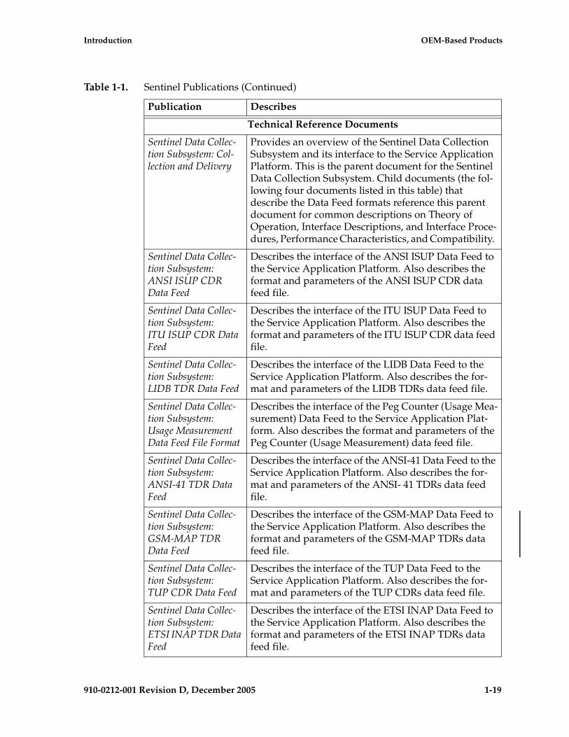
Introduction OEM-Based Products
910-0212-001 Revision D, December 2005 1-19
Technical Reference Documents
Sentinel Data Collec-tion Subsystem: Col-lection and Delivery
Provides an overview of the Sentinel Data Collection Subsystem and its interface to the Service Application Platform. This is the parent document for the Sentinel Data Collection Subsystem. Child documents (the fol-lowing four documents listed in this table) that describe the Data Feed formats reference this parent document for common descriptions on Theory of Operation, Interface Descriptions, and Interface Proce-dures, Performance Characteristics, and Compatibility.
Sentinel Data Collec-tion Subsystem:ANSI ISUP CDR Data Feed
Describes the interface of the ANSI ISUP Data Feed to the Service Application Platform. Also describes the format and parameters of the ANSI ISUP CDR data feed file.
Sentinel Data Collec-tion Subsystem:ITU ISUP CDR Data Feed
Describes the interface of the ITU ISUP Data Feed to the Service Application Platform. Also describes the format and parameters of the ITU ISUP CDR data feed file.
Sentinel Data Collec-tion Subsystem:LIDB TDR Data Feed
Describes the interface of the LIDB Data Feed to the Service Application Platform. Also describes the for-mat and parameters of the LIDB TDRs data feed file.
Sentinel Data Collec-tion Subsystem:Usage Measurement Data Feed File Format
Describes the interface of the Peg Counter (Usage Mea-surement) Data Feed to the Service Application Plat-form. Also describes the format and parameters of the Peg Counter (Usage Measurement) data feed file.
Sentinel Data Collec-tion Subsystem:ANSI-41 TDR Data Feed
Describes the interface of the ANSI-41 Data Feed to the Service Application Platform. Also describes the for-mat and parameters of the ANSI- 41 TDRs data feed file.
Sentinel Data Collec-tion Subsystem:GSM-MAP TDR Data Feed
Describes the interface of the GSM-MAP Data Feed to the Service Application Platform. Also describes the format and parameters of the GSM-MAP TDRs data feed file.
Sentinel Data Collec-tion Subsystem:TUP CDR Data Feed
Describes the interface of the TUP Data Feed to the Service Application Platform. Also describes the for-mat and parameters of the TUP CDRs data feed file.
Sentinel Data Collec-tion Subsystem:ETSI INAP TDR Data Feed
Describes the interface of the ETSI INAP Data Feed to the Service Application Platform. Also describes the format and parameters of the ETSI INAP TDRs data feed file.
Table 1-1. Sentinel Publications (Continued)
Publication Describes

1-20 910-0212-001 Revision D, December 2005
Customer Care Center Introduction
Documentation Packaging, Delivery, and Updates
Customer documentation is provided with each system and is shipped to the sites specified by the customer. The number of documentation sets provided are in accordance with the contractual agreements.
Customer documentation is updated whenever significant changes are made that affect system operation or configuration. Updates may be issued in the form of an addendum or a reissue of the relevant documentation.
The document part number is shown on the title page along with the current revision of the document and the date of publication. The bottom of each page contains the document’s date of publication and the document’s part number.
When a document is reissued, the following information changes:
• The title page and revision number, the date of publication, and the new software release number, if applicable.
• The date of publication and the document part number, if applicable, on the bottom of each page.
References
The following documents are referenced in this manual:
GR-63-CORE “Network Equipment-Building System (NEBS) Requirements”, Issue 1, October 1995GR-1244-CORE “Clocks for the Synchronized Network Common Generic Criteria”, Issue 2, December 2000GR-376-CORE “Network Data Collection”, Issue 3, December 1998“TL-9000 Quality System Metrics (Book Two, Release 3.0)”
Customer Care Center
The Customer Care Center offers a point of contact through which customers can receive support for problems that may be encountered during the use of Tekelec’s products. The Customer Care Center is staffed with highly trained engineers to provide solutions to your technical questions and issues seven days a week, twenty-four hours a day. A variety of service programs are available through the Customer Care Center to maximize the performance of Tekelec products that meet and exceed customer’s needs.
To receive technical assistance, call the Customer Care Center at one of the following locations:
• Tekelec, USA
Phone (US and Canada) +1 888-FOR-TKLC
Phone (international) +1 919-460-2150

Introduction Customer Care Center
910-0212-001 Revision D, December 2005 1-21
Fax +1-919-460-0877
Email: [email protected]
• Tekelec, Europe and UK
Phone +44 1784 467 804
Fax +44 1784 477 120
Email: [email protected]
Once a Customer Service Request (CSR) is issued, Technical Services, along with the customer, determines the classification of the trouble.
Problems are reported using problem criteria, as defined in the following sections and “TL-9000 Quality System Metrics (Book Two, Release 3.0)” .
Problem – Critical
Critical problems severely affect service, capacity/traffic, billing, and maintenance capabilities and requires immediate corrective action, regardless of time of day or day of the week, as viewed by a customer upon discussion with the supplier. For example:
• A loss of service that is comparable to the total loss of effective functional capacity of an entire switching or transport system.
• A reduction in capacity or traffic handling capacity such that expected loads cannot be handled.
• loss of ability to provide safety or emergency capability (for example, 911 calls).
Problem – Major
Major problems cause conditions that seriously affect system operations, or maintenance and administration, and require immediate attention as viewed by the customer upon discussion with the supplier. Because of a lesser immediate or impending effect on system performance, the urgency is less than in a critical situation. A list of possible examples follows:
• Reduction in any capacity/traffic measurement function
• Any loss of functional visibility and/or diagnostic capability
• Short outage equivalent to system or subsystem outages with accumulated duration of greater than two minutes in any 24-hour period or that continue to repeat during longer periods
• Repeated degradation of DS1 or higher rate spans or connections
• Prevention of access for routine administrative activity
1-22 910-0212-001 Revision D, December 2005
Customer Care Center Introduction
• Degradation of access for maintenance or recovery operations
• Degradation of the system’s ability to provide any required critical or major trouble notification
• Any significant increase in product-related customer trouble reports
• Billing error rates that exceed specifications
• Corruption of system or billing databases
Problem – Minor
Other problems that a customer does not view as critical or major are considered minor. Minor problems do not significantly impair the functioning of the system and do not significantly affect service to customers. These problems are tolerable during system use.
Engineering complaints are classified as minor unless otherwise negotiated between the customer and supplier.

Introduction Response
910-0212-001 Revision D, December 2005 1-23
Response
If a critical problem exists, emergency procedures are initiated (see “Emergency Response”). If the problem is not critical, information regarding the serial number of the system, Common Language Location Identifier (CLLI), and initial problem symptoms and messages is recorded and a primary Technical Services engineer is assigned to work the Customer Service Request (CSR) and provide a solution to the problem. The CSR is closed when the problem has been resolved.
Emergency Response
In the event of a critical service situation, emergency response is offered by the Tekelec Customer Care Center.
To receive technical assistance, call the Customer Care Center at one of the following locations:
• Tekelec, USA
Phone (US and Canada) +1 888-FOR-TKLC
Phone (international) +1 919-460-2150
Fax +1-919-460-0877
Email: [email protected]
• Tekelec, Europe and UK
Phone +44 1784 467 804
Fax +44 1784 477 120
Email: [email protected]
Emergency response provides immediate coverage, automatic escalation, and other features to ensure a rapid resolution to the problem.

1-24 910-0212-001 Revision D, December 2005
Hardware Repair and Return Introduction
Hardware Repair and Return
Any system components being returned for repair or replacement must be processed through the Tekelec Return Material Authorization (RMA) procedures. A hardware repair is defined as an item returned to Tekelec due to a failure, with the returned item being repaired and returned to the customer. It is essential that serial numbers are recorded correctly. RMAs cannot be created without a valid serial number. All repair and quality information is tracked by serial number. Table 1-2 lists the basic RMA types.
Table 1-3 lists the RMA return reasons.
Table 1-2. Basic RMA Types
Replacement Type
Description Turnaround
Priority Advance Replacement
Customer requests the URGENT replacement of a damaged product Same Day Shipment
Advance Replacement
Customer request the replacement of a damaged product
Shipment Within 3 Business Days
Repair / Return Customer will return a damaged product for repair
Shipment Within 5 Days After Receipt
ExpendableA damaged part, such as a cable, is replaced, but the Customer does not return the damaged product
Depends on Urgency - Shipment Within 3 Business Days
Table 1-3. RMA Reasons for Return
Reason for Return Description
Damaged by Environment
Product damaged by environmental phenomena such as water damage or earthquake
Damaged in Shipment Damaged between shipment from Tekelec and receipt at the Customer’s installation site.
DOA – Dead on Arrival Product is not functional when it is first installed at the Customer’s location.
Lab Return Products returned from lab sites.
Product Capture Defect to be captured by Quality or Engineering (not Product Recall).
Product Deficiency Anything wrong with the part that doesn’t fall into another category.
Product Recall Products recalled by divisions for the repair of a defect or replacement of defective products.
Return – No Product Deficiency Anything returned without the product being defective.

Introduction Hardware Repair and Return
910-0212-001 Revision D, December 2005 1-25
Repair and Return Shipping Instructions
All returned equipment, assemblies, or subassemblies must be shipped to the Tekelec Repair and Return Facility specified by the Technical Services engineer. The item being returned must be shipped in the original carton or in an equivalent container assuring proper static handling procedures and with the freight charges prepaid.
The assigned RMA number must be clearly printed on the “RMA#:” line of the shipping label on the outside of the shipping package. If the RMA number is not placed on the label, the return could be delayed.
Procedure- RMA
1 Obtain and confirm the following information before contacting the Tekelec Customer Contact Center:
• Your name:
• Company name:
• Call-back number:
• Email address:
• Which product you are calling about?
• Site location:
• CLLI number
• System serial number (NT, CE, LM, DS, etc…):
• Complete software release (e.g., 28.0.1-41.53.0):
• Upgrade formsWI005153WI005154WI005218

1-26 910-0212-001 Revision D, December 2005
Hardware Repair and Return Introduction
WI005219WI005220
• Tekelec card type: (e.g., ILA, MPL, DSM, etc.):
• Tekelec card part number (870-####-##):
• Associated serial number (102########):
• Reason for return or replacement (isolated from system):
• Full name of person the replacement card is being shipped to:
• Shipping address:
NOTE: If possible, include associated alarms (UAMs) and a copy of the associated output (capture file).
2 Contact the Contact Customer Contact Center and request a Return of Material Authorization (RMA).
Reference: “Customer Care Center” on page 1-20.
3 If the item is a like-for-like advance replacement, the Technical Services engineer arranges for shipment of the replacement item to the customer.
a Wait for the replacement component to arrive.
b Package the defective component in the box of materials you received with your replacement. Use proper static handling procedures.
c Label the outside and inside of the box with your RMA number clearly visible. Place the packing slip from the received replacements on the inside of your box.
d Ship the defective component to the return address listed on the packing slip.
4 If the item is a repair/return, the Technical Services engineer arranges for shipment of the replacement item to the customer.
a Package the defective component in a suitable package for shipping. Use proper static handling procedures.
b Label the outside and inside of the box with your RMA number clearly visible. Include a packing slip with all the information from Step 1 along with the RMA number.

Introduction Hardware Repair and Return
910-0212-001 Revision D, December 2005 1-27
c Ship the defective component to the following address:
TEKELEC
Attn: RMA Department
5200 Paramount Parkway
Morrisville, NC 27560
RMA#: <assigned by Tekelec>
d Wait for the repaired component to arrive.
Repair and Return Shipping Instructions
Returned equipment, assemblies, or subassemblies must be shipped to the Tekelec Repair and Return Facility specified by the Technical Services engineer unless it is a Specifically Targeted PCB.
Returned items must be shipped in the original carton or equivalent container, assuring proper static handling procedures and with the freight charges prepaid. The assigned RMA number must be clearly printed on the “Attn:” line of the shipping label on the outside of the shipping package. The unit must also be tagged with the reason it is being returned. If the RMA number is not placed on the label, the return could be delayed.
General Instructions
Ship to:
TEKELEC
Attn: RMA Department
5200 Paramount Parkway
Morrisville, NC 27560
RMA#: <assigned by Tekelec>
Specifically Targeted PCBs
Manufacturing may be involved in the investigations. In certain unique circumstances the capture of an individual PCB, for evaluation, can be initiated through a customer request.
1-28 910-0212-001 Revision D, December 2005
Hardware Repair and Return Introduction
For any reason the Director of Quality (QA) with input from other groups such as NSD Customer Service, Hardware Systems, Repair and Maintenance Support (RMS) and/or Manufacturing can authorize a board type to be "captured" and sent to the North Carolina facility for evaluation and analysis. NSD QA receives the board(s), records board information, such as part number and serial number and problem description on the appropriate forms and sends the PCB to a Hardware Systems representative who initiates the design engineering evaluation. Once the evaluation and repair, if applicable, is complete, the results are documented and the PCB returned to NSD QA.
Returning a Crate
Use the following procedure to return a shipping crate and dollies to Tekelec.
Procedure — Preparing Crate and Dolly for Return to Tekelec
1. Replace the retaining brace.
2. Replace the shipping container front panel using the bolts saved previously and arrange the return shipment by contacting:
Shipping ManagerTEKELEC
Attn: RMA Department
5200 Paramount Parkway
Morrisville, NC 27560
RMA#: <assigned by Tekelec>
3. After the frame is positioned and the dollies are removed from the frame, the dollies are returned to the same address as the shipping container listed above.
If the equipment is being immediately installed ship the dollies back to Tekelec in the crate after use. After installing the equipment bolt the dollies securely in the crate and return to Tekelec.
OR
If the equipment is not being immediately installed ship the dollies back to Tekelec in the box supplied with the crate. After unpacking the equipment return the crate to Tekelec and retain the box to return the dollies. After installing the equipment remove the dollies and return to Tekelec in the supplied box.

Introduction Hardware Repair and Return
910-0212-001 Revision D, December 2005 1-29
NOTE: It is the site supervisor’s responsibility to assure the crate and dollies are returned to Tekelec.
1-30 910-0212-001 Revision D, December 2005
Acronyms Introduction
Acronyms
A.......................................... Ampere
ACL .................................... Application processor Code Loader
ACM................................... Applications Communications Module
AIN..................................... Advanced Intelligent Networks. Set of standards for advanced intelligent services
AINF................................... Application Interface Applique
ANSI................................... American National Standards Institute.
AP ....................................... Application Processor
APD .................................... Application Processor DCM bootstrap code
API...................................... Application Interface
AS ....................................... Application server
ASM.................................... Application Services Module
ATM.................................... Asynchronous Transfer Mode
BHCA................................. Busy Hour Call Attempts
BITS .................................... Building Integrated Timing System
BM ...................................... Buss Master (Cognitronics)
BOM ................................... Bill Of Materials
BP........................................ Boot Prom
BPDCM .............................. Boot Prom DCM
Bps ...................................... Bit per second
CAP .................................... Communication & Application Processor
CAR .................................... Corrective Action Report
CE CISPR A....................... Compliance European, Comite Internationale Special des Perturbations Radioelectrique (European Compliance, International Special Committee on Radio Interference, Class A)
CDR .................................... Call Detail Record
CDU.................................... CAP Downloadable Utility
CLEI.................................... Common Language Equipment Identifier
CF........................................ Control Frame

Introduction Acronyms
910-0212-001 Revision D, December 2005 1-31
CLLI ................................... Common Language Location Identifier
CNAM ............................... Calling Name Delivery Service
COTS.................................. Commercial Off-the-Shelf
CP ....................................... Communications Processor
CSR..................................... Customer Service Request
D1G .................................... Database Communication 1 Gigabyte Expansion Memory Module
DCM................................... Database Communications Module
DMS.................................... Disk Management Service
DRAM................................ Dynamic Random Access Memory
DS0 ..................................... Digital Signal Level-0 (64 Kbits/sec)
DS1 ..................................... Digital Signal Level-1 (1.544Mbits/sec)
DSM.................................... Database Services Module
E1 ........................................ European Digital Signal Level-1 (2.048 Mbits/sec).
EBI ...................................... Extended Bus Interface
EDCM ................................ Enhanced Database Communications Module
EF........................................ Extension Frame
EILA ................................... Enhanced Integrated LIM Applique
EMM................................... Extended Memory Management
EMP.................................... EAGLE Monitor Protocol
EOAM ................................ Enhanced OAM GPL
EOAP ................................. Embedded Operation Support System Applications Processor
ESD..................................... Electro-Static Discharge
ESP...................................... Extended Services Platform
FAP ..................................... Fuse and Alarm Panel
FR........................................ Flight Recorder
FTP...................................... File Transfer Protocol
GB ....................................... GigaByte
GLS..................................... Generic Loader Services
GPL..................................... Generic Program Load
1-32 910-0212-001 Revision D, December 2005
Acronyms Introduction
GPLM................................. GPL Management
GPSM-II ............................. General Purpose Service Module
GTT..................................... Global Title Translation
GWS.................................... GTT Gateway Screening
HCAP ................................. High-Speed Communications & Applications Processor
HCAP-T ............................. Improved HCAP card
HCMIM.............................. High Capacity Multi-Channel Interface Module
HDLC ................................. High-Level Data Link Control
HIPR................................... High-speed IMT Packet Router
HMUX................................ High-speed Multiplexer
IAD ..................................... Integrated Access Device
ICM..................................... IMT configuration manager task
ILA...................................... Integrated LIM-AINF module
ILDR ................................... IMT loader task
IMT ..................................... Inter-processor Message Transport
IMTC .................................. IMT Control task
IP......................................... Internet Protocol
IP7 ....................................... Tekelec’s Internet Protocol to SS7 Interface
IPD...................................... IMT Processor DCM operational code
IPMX .................................. IMT Power and Multiplexer card
ISDN................................... Integrated Services Digital Network.
IS-NR.................................. In Service – Normal
ISR....................................... Interrupt Service Routine
ITU...................................... International Telecommunications Union
IWF ..................................... Inter-Working Function
KHz .................................... Kilo Hertz (1000 Hertz)
LAN.................................... Local Area Network.
LFS...................................... Link Fault Sectionalization
LIM ..................................... Link Interface Module
Introduction Acronyms
910-0212-001 Revision D, December 2005 1-33
LNP .................................... Local Number Portability
LIM-AINF.......................... A LIM with a software-selectable interface
LOM ................................... Lights out Management
LSMS .................................. Local Service Management System
M256................................... 256 Megabyte Memory Expansion Card
MAS.................................... Maintenance and Administration Subsystem
MASP ................................. Maintenance and Administration Subsystem Processor
MBUS ................................. Maintenance Bus
MCAP ................................ Maintenance Communications & Applications Processor
MDAL ................................ Maintenance, Disk, and Alarm card
MG...................................... Media Gateway
MGB ................................... Master Ground Bar
MGC................................... Media Gateway Controller
MGCP ................................ Media Gateway Controller Protocol
MIB..................................... Maintenance Information Base utility
MIM.................................... Multi-Channel Interface Module
MPL.................................... Multi-Port LIM
MPS .................................... Multi-Purpose Server
MSU.................................... (SS7) Message Signalling Unit
MS....................................... Media Server
MTOS ................................. Multi-Tasking Operating System, Industrial Programming Inc.
NEBS .................................. Network Equipment Building System
NOC ................................... Network Operations Center
NS ....................................... Network Server
NSD .................................... Tekelec’s Network Systems Division
OAM .................................. Operations, Administration, & Maintenance
OA&M ............................... Operations, Administration, & Maintenance
OAP.................................... Operations System Support/Applications Processor
1-34 910-0212-001 Revision D, December 2005
Acronyms Introduction
OAPF.................................. Operations System Support/Applications Processor Frame
OCU.................................... Office Channel Unit
OEM ................................... Original Equipment Manufacturer
OOS-MT-DSBLD .............. Out of Service –Maintenance Disabled
PMTC ................................. Peripheral Maintenance task
PSTN .................................. Public Switched Telephone Network
RAID .................................. Redundant Array of Inexpensive Disks
RAM ................................... Random Access Memory
RMA ................................... Return Material Authorization
SAI/P ................................. Serial Asynchronous Interface PCI Adapter
SAS ..................................... Signaling Application System
SCP ..................................... Service Control Point (SS7 Network)
SCCP................................... Signal Connection Control Part
SCM.................................... System Configuration Manager
SCN .................................... Switched Circuit Network
SCSI .................................... Small Computer Systems Interface
SEAC .................................. Signaling Engineering and Administration Center
SEAS................................... Signaling Engineering and Administration System
SG........................................ Secure Gateway
SIP....................................... Session Initiation Protocol
SS7....................................... Signaling System Seven
SSP ...................................... Service Switching Point (SS7 Network)
STC ..................................... Sentinel Transport Card
STP...................................... Signal Transfer Point (SS7 Network)
STPLAN............................. Signaling Transfer Point Local Area Network
T1 ........................................ The North American telecommunications standard defining a circuit that multiplexes and switches 24 channels and operates at speeds of 1.544 Mbps
Tekelec 1000....................... Tekelec 1000 Application Server
TCU .................................... Table Creation Utility

Introduction Acronyms
910-0212-001 Revision D, December 2005 1-35
TCP..................................... Transport Control Protocol
TCP/IP............................... Transmission Control Protocol/Internet Protocol
TDM ................................... Terminal Disk Module
TEKCC ............................... Tekelec Composite Clock
TEKOS ............................... Tekelec Operating System
TMOAP.............................. Texas Micro processor chassis hosting the OAP application
TOS486............................... Tekos Operating System for the 486
TOS4M ............................... Tekos Operating System for the 486 implemented via MTOS
TSC ..................................... Time Slot Counter
TSM .................................... Translation Services Module
UAM................................... Unsolicited Alarm Output
UD1G ................................. Updated Database Communication 1 Gigabyte Expansion Memory Module
UIM .................................... Unsolicited Information Messages
V.35 ..................................... ITU Interface Recommendation, V.35
VPN.................................... Virtual Private Network
WAN .................................. Wide Area Network

1-36 910-0212-001 Revision D, December 2005
Acronyms Introduction
910-0212-001 Revision D, December 2005 2-1
2
Systems Overview
Introduction ...................................................................................................... 2-2
EAGLE 5 SAS and IP7 Secure Gateway Systems.........................................2–3
Maintenance and Administration Subsystem.......................................2–4
Communication Subsystem .....................................................................2–6
Application Subsystem.............................................................................2–8
Timing Systems EAGLE 5 SAS STP/IP7 SG ........................................2–15
High-Speed Master Timing....................................................................2–18
Time Slot Counter Synchronization......................................................2–18
Embedded Operations Applications Processor ..................................2–18
GR-376 EOAP...........................................................................................2–19
Integrated Sentinel .........................................................................................2–20
Integrated Sentinel on the EAGLE 5 SAS STP Side............................2–22
Integrated Sentinel (ESP Frame Side)...................................................2–23
OEM-Based Products and Elements............................................................2–24
ASi 4000 SCP ............................................................................................2–24
Multi-Platform Server (MPS) Systems..................................................2–24
Operations Support System Applications Processor .........................2–25
AXi Systems..............................................................................................2–26
Non-Integrated Sentinel Solutions........................................................2–29
2-2 910-0212-001 Revision D, December 2005
Systems Overview
Components of OEM-Based Products........................................................ 2–30
OEM-Based Network Elements ............................................................ 2–30
OEM-Based Peripheral Components ................................................... 2–31
Introduction
This chapter introduces the hardware in Tekelec Network Systems Division (NSD) products. This manual describes hardware components for all NSD system configurations. Appendix A, Hardware Baselines, in this manual lists specific hardware (required or configurable components) by part number for each system type and release.
The following sections provide an overview of these NSD products.
• “EAGLE 5 SAS and IP7 Secure Gateway Systems” on page 2-3
• “OEM-Based Products and Elements” on page 2-24
NOTE: Some NSD systems are configured with integrated EAGLE 5 SAS and OEM-based products. Integrated products are described generally in this chapter and in detail in Chapter 3, Hardware Descriptions — EAGLE/IP7 SG-Based Products and Chapter 5, Hardware Descriptions — Sentinel Products.
• Elements used in OEM-Based products are described in the section “Components of OEM-Based Products” on page 2-30.
In this document modules or components that are used only in specific systems or releases are noted in the following syntax.
• Components used only in EAGLE 5 SAS STP systems are labeled (EAGLE 5 SAS STP only)
• Components used only in IP7 Secure Gateway (SG) systems are labeled (IP7 SG only)
• Components that are specific to a system and release are labeled with the system and release. For example, (IP7 SG 4.0 and later) or (Integrated Sentinel 8.0 and later)
NOTE: The term “module” refers to a hardware card provisioned with software. In some cases EAGLE 5 SAS cards are referred to by the name of the module in which they function, rather than the card name that appears on the label of the card. For ordering or service purposes, customers should use the card name and part number printed on the card itself.

Systems Overview
910-0212-001 Revision D, December 2005 2-3
EAGLE 5 SAS and IP7 Secure Gateway Systems
EAGLE 5 SAS STP and IP7 SG systems are mounted in the same types of frames and are configured similarly. In Chapter 3, “Hardware Descriptions — EAGLE/IP7 SG-Based Products,” specific component requirements or configurations for each system are explained in detail.
EAGLE 5 SAS STP and IP7 SG systems consist of the following subsystems:
• Maintenance and Administration Subsystem (MAS)
• Communication Subsystem
• Application Subsystem
In addition, EAGLE 5 SAS STP and IP7 SG systems have a clock derived from the Building Integrated Timing System (BITS). This connects to the 64KHz composite BITS signal and distributes clock signals to the rest of the cards in the systems.
NOTE: See the section “Timing Systems EAGLE 5 SAS STP/IP7 SG” on page 2-15 for information about High-Speed Master Timing and Time Slot Counter (TSC) Synchronization features.

2-4 910-0212-001 Revision D, December 2005
Systems Overview
Figure 2-1. EAGLE 5 SAS STP/IP7 SG Subsystems
Maintenance and Administration Subsystem
The Maintenance and Administration Subsystem (MAS) provides services to other subsystems, and consists of the following:
• The General Purpose Service Module (GPSM-II)
• Terminal Disk Module (TDM)
• Maintenance Disk and Alarm (MDAL)
NOTE: Beginning with EAGLE STP Software Release 30.0 all MCAP cards must be replaced by GPSM-II cards (P/N 870-2360-01), and Terminal Disk Module cards must be P/N 870-0774-10 or later. GPSM-II cards are installed at the factory or by Tekelec Technical Support and are not installed by customers.
Maintenanceand Administration
Subsystem
General Purpose Service Module (GPSM-II)Terminal Disk Module (TDM)
Maintenance Disk and Alarm Card (MDAL)
Communication SubsystemMicroprocessor Message Transport (IMT)Small Computer System Interface (SCSI)
High-Speed Multiplexor (HMUX)
Optional SentinelTransport Cards
(STC)or
MaintenancePolling
and CollectionModules (MCPM)
ApplicationService
Module (ASM)
TranslationService
Module (TSM)
Link InterfaceModule (LIM)
DatabaseCommunicationsModule (DCM)
Database ServiceModule (DSM)
ApplicationCommunicationModule (ACM)
Application Subsystemsubsystem
Systems Overview
910-0212-001 Revision D, December 2005 2-5
MASP
The Maintenance and Administration Subsystem Processor (MASP) function is a logical pairing of the GPSM-II card and the TDM card. The GPSM-II card is connected to the TDM card by means of an Extended Bus Interface (EBI) local bus.
The MDAL card contains the removable cartridge drive and alarm logic. There is only one MDAL card in the Maintenance and Administration Subsystem (MAS) and it is shared between the two MASPs.
The GPSM-II and TDM card combination performs the following functions:
• Maintenance communication—Maintenance functions poll each application card and receives trouble reports. These are reported to the alarm function in the MASP to generate alarms, or to the event messaging function for output to the printer.
• Measurements—Collection and reporting of system performance data.
• Peripheral services—Provides access to all peripherals attached to the system, terminals, disks, alarms, clocks, and others.
• Alarm processing—Provides audible and visual alarms.
• System disks—Provides for storage of application or system software.
Software is downloaded to application cards from the MASP. The software provides the interface function depending on application requirements. The type of software the application processor receives depends on the function of the application board which is determined by provisioning the board.
EAGLE 5 SAS STP System architecture provides Inter-processor Message Transport (IMT) connectivity directly to the maintenance and administration subsystem through the GPSM-II card. This allows the MASP to provide maintenance and administrative communication services to application cards.
Figure 2-2, “Maintenance and Administration Subsystem,” on page 2-6 shows relationships between different components of the maintenance and administration subsystem.

2-6 910-0212-001 Revision D, December 2005
Systems Overview
Figure 2-2. Maintenance and Administration Subsystem
Communication Subsystem
The communication subsystem consists of two separate sets of buses:
• Small Computer System Interface (SCSI) buses
• Inter-processor Message Transport (IMT) buses
Small Computer System Interface Buses
There are two independent Small Computer System Interface (SCSI) buses, one to the fixed disks on TDM cards and the other to the shared administration SCSI bus that runs on the backplane between TDMs and the MDAL card. Each SCSI bus has a block of memory that allows transfers from memory to occur without delaying the application processor.
Inter-processor Message Transport
The Inter-processor Message Transport (IMT) bus is the main communications artery for all subsystems in the system. The IMT bus uses load sharing, so messages from the various subsystems are divided evenly across both buses. If one bus should fail, the other immediately assumes control of all messages.
�������������� ����� ������������ ���
��������� ���������
���������������������������
������������
����������
����������
�������� ���!�"�
#��$
����
����������%�&��#��$
���%�&��#��$
�����"
�������
Systems Overview
910-0212-001 Revision D, December 2005 2-7
NOTE: With EAGLE (release 28.0 and later)/Integrated Sentinel (release 8.0 and later) the IMT buses can function as a private LAN assigning internal IP address to LIM cards. By addressing cards on an internal LAN, the EAGLE/Sentinel Integration feature allows monitoring of SS7 links without external connections. SS7 link information from the EAGLE 5 SAS STPLIM cards is collected by Sentinel Transport Cards (STC) and transferred to Expanded Service Platform (ESP) subassemblies. After processing in the ESP, the link information is forwarded to a Sentinel server.
The High-Speed IMT Packet Router
The High-Speed IMT Packet Router (HIPR) Module (P/N 870-2574-01) provides increased IMT bus bandwidth and individual high-speed card/server links. The HIPR enhances the IMT bus by introducing switched 125 Mbps interfaces to each slot within a shelf. HIPR acts as a gateway between the intra-shelf IMT BUS, running at 125 Mbps, and the inter-shelf ring operating at 1.0625 Gbps. HIPR implements the HMUX scheme of transmitting data between shelves only when necessary. The HIPR plugs into the same slot as an HMUX.
Traffic between cards on the same shelf will be switched directly to the destination slot and is not transmitted to any other cards in the shelf. Traffic between shelves is not required to pass onto an intra-shelf IMT channel.
Two HIPR modules are required in shelves equipped with high-performance LIMs, such as the High-Capacity MIM, and for interfacing to Tekelec 1000 Application Server through IMT Bridge and IMT PCI modules. HIPR requires all other shelves be equipped with either all HMUX cards or all HIPR cards (shelves cannot contain a mix of HMUX and HIPR).
The HIPR programmable logic is upgradeable and reprogrammable via the IMT inter-shelf interface. Updated images can be downloaded from the OAM to the HIPR and stored in FLASH memory on the HIPR.
With the improved bandwidth from the switched architecture, the HIPR card enables customers to use other higher performance cards from Tekelec such as the High Capacity MIM.
NOTE: Beginning with EAGLE STP Software Release 30.0 all IPMX cards must be replaced by High-Speed Multiplexer (HMUX) cards (P/N 870-1965-01). Beginning with EAGLE STP software release 33.0, all IPMX cards must be replaced by either HMUX cards or High-Speed IMT Router (HIPR) Cards (P/N 870-2574-01). A mixture of HMUX and HIPR cards within one IMT ring is possible, provided HIPR is installed on both IMT A and IMT B on a given shelf. HMUX and HIPR cards are installed at the factory or by Tekelec Technical Support and are not installed by customers.

2-8 910-0212-001 Revision D, December 2005
Systems Overview
High-Speed Multiplexer
High-Speed Multiplexer (HMUX) cards support requirements for up to 1500 links, allowing communication on IMT buses between cards, shelves and frames. HMUX cards interface to 16 serial links, creating a ring from a series of point to point links. Each HMUX card provides a bypass multiplexer to maintain the ring's integrity as cards are removed and inserted into an operational shelf.
NOTE 1: To maintain integrity of the IMT bus, each extension shelf must contain at least one Translation Service Module (TSM) or Database Communications Module (DCM), or Link Interface Module (LIM). If such cards are present for the purpose of maintaining IMT bus integrity, they do not have to be entered into the system database .
NOTE 2: Control Shelf Backplane (P/N 850-0330-05) can not be used with EAGLE STP Software Release 30.0. Control Shelf Backplane (P/N 850-0330-03/04) can be used with the HMUX and HIPR in the EAGLE 5 SAS STP system with minor modifications and the addition of adapter cable (P/N 830-0857-01). The adapter cable is not necessary for customers not wanting high speed links.
NOTE 3: Beginning with EAGLE STP Software Release 30.0 all IPMX cards must be replaced by High-Speed Multiplexer (HMUX) cards (P/N 870-1965-01). Beginning with EAGLE STP software release 33.0, all IPMX cards must be replaced by either HMUX cards or High-Speed IMT Router (HIPR) Cards (P/N 870-2574-01). A mixture of HMUX and HIPR cards within one IMT ring is possible, provided HIPR is installed on both IMT A and IMT B on a given shelf. HMUX and HIPR cards are installed at the factory or by Tekelec Technical Support and are not installed by customers.
Application Subsystem
The application subsystem consists of application cards. Application cards are capable of communicating with other cards through the redundant IMT buses. A Communications Processor (CP) on each application board provides control of communications from the cards to the IMT buses.
Software is downloaded to application cards on initial power-up from the Maintenance and Administration Subsystem Processors (MASP). Once EAGLE 5 SAS STP and IP7 SG systems are loaded, software is downloaded to cards by the Generic Loader Services (GLS) and Operation Administration and Maintenance (OAM).
Systems Overview
910-0212-001 Revision D, December 2005 2-9
An Application Processor (AP) receives the software load on the application card. The type of software the AP receives depends on the function of the application board which is determined by the provisioning of the board. Presently, there are several types of application cards that support network specific functions:
• Link Interface Module (LIM)—SS7 links and X.25 links
• Application Communication Module (ACM)—Transmission Control Protocol/Internet Protocol (TCP/IP) interface over Ethernet for the Signaling Transfer Point Local Area Network (STPLAN) feature.
NOTE: Ethernet is a standard set of specifications for a particular type of LAN that employs baseband signaling (single signal on a cable) and has a transmission rate of 10/100 Mbps
• Application Service Module (ASM)—Signaling Connection Control Part (SCCP) Global Title Translation (GTT), GTT Gateway Screening (GWS), or Generic Loader Services (GLS).
NOTE: Beginning with EAGLE release 31.6 ASM cards will no longer be supported and must be replaced by TSM cards. SCCP, GTT, GWS, and GLS functions will be provided by TSM cards. For more information see (see “Application Service Module” on page 3-88).
• Database Communications Module (DCM), Enhanced DCM (EDCM and EDCM-A), Sentinel Transport Card (STC)—Transmission Control Protocol/Internet Protocol (TCP/IP) interface over Ethernet for the Signaling Transfer Point Local Area Network (STPLAN) feature.
• Translation Service Module (TSM)—Local Number Portability (LNP)/SCCP (GTT) only
• Database Service Module (DSM)—EAGLE Provisioning Application Processor (EPAP), Global System for Mobile Communications (GSM), EAGLE Local Number Portability (ELAP), and interface to Local Service Management System (LSMS)
NOTE: Beginning with EAGLE release 29.0 a DSM card type is available based on the General Purpose Service Module-II (GPSM-II).
DSM-1G cards based on the GPSM-II card running the IPS GPL function as card type IPSM.
• General Purpose Service Module II (GPSM-II)— The GPSM-II provides two 10/100Base-T Ethernet ports for LAN connections. The GPSM-II does not require additional memory modules when provisioned as a single slot EDCM.
NOTE: Beginning with EAGLE release 30.0, all MCAP cards must be replaced by GPSM-II cards (P/N 870-2360-01). GPSM-II cards are installed at the factory or by Tekelec Technical Support and are not installed by customers.

2-10 910-0212-001 Revision D, December 2005
Systems Overview
When the GPSM-II is combined with one or more Gigabytes of expansion memory (UD1G P/N 850-0527-xx) it becomes the primary board for the following card types. GPSM-II card functionality is primarily determined by the GPL provisioned.
— When combined with a one Gigabyte (UD1G) expansion memory board in a single-slot assembly and provisioned with IPS GPL, the GPSM-II functions as card type IP Services Module (IPSM).
— Prior to EAGLE 31.6, when combined with two UD1G expansion memory boards in a single-slot assembly, the GPSM-II card functions as Measurement Collection and Polling Module (MCPM)—STP, LNP, INP, G-FLEX, and G-PORT Measurements data with File Transfer protocol (FTP). Beginning with EAGLE release 31.6, the Measurements Collection and polling Module (MCPM) is derived from EDSM-2G cards with 32 MB FSRAM and 2 GB RAM.
NOTE: The EDSM-2G card in the MCPM module is a requirement for the FTP measurements feature. The FTP measurements feature uses the MCPM card ethernet ports to transfer measurements information directly to a FTP server.
• Multi-Channel Interface Module—8 HDLC channels for E1 or T1 protocols
• Multi-Port Link Interface Module—SS7 links
Generic Program Loads
Application software is downloaded to individual application cards by means of Generic Program Loads (GPLs). Hardware is defined to EAGLE 5 SAS STP and IP7 SG systems by means of a series of administration commands. Software is then loaded from the fixed disk over the IMT bus directly to the cards. The type of the GPL loaded depends on the card that is chosen.
GPLs can be any of the following:
• SCCP —Signaling Connection Control Part. This software allows the Translation Service Module (TSM) to be used as a memory board for Global Title Translation (GTT). Inbound SCCP messages from Link Interface Modules (LIMs) are sent to the TSM assigned to the LIM by system software. SCCP software on the TSM performs the translation, and sends messages through the IMT back to the appropriate LIM, which routes messages to the destination. The SCCP application can run on the TSM and DSM cards.
NOTE: It is Tekelec's recommendation that cards running the SCCP application be uniformly distributed in the EAGLE 5 SAS STP to provide a more even SCCP load distribution. During normal operation unevenly distributed SCCP cards in an
Systems Overview
910-0212-001 Revision D, December 2005 2-11
NOTE: EAGLE 5 SAS STP would not have any network or system impacts. However, should a particular SCCP card database(s) become corrupted, inconsistent, or at a different level, depending on the amount of service provided by that card and the extent of the database issue, network impacts can occur.
• SLAN—Signaling Transfer Point Local Area Network. This software allows the system to support a TCP/IP interface to any external host with ACMs and DCMs.
• SS7—This software provides access to remote SS7 network elements.
• GX25—This software allows the system to send and receive traffic to and from an X.25 network, and convert the packet to an Signaling System #7 Message Signaling Unit (SS7 MSU).
• GLS—Gateway Loading Service (GLS) software controls download of Gateway Screening (GWS) data to Link Interface Modules (LIMs) and TSM when necessary. This ensures a fast download of gateway screening data when a card re-initializes.
Gateway screening data is downloaded when a card is re-initialized, when Gateway screening is changed by database administration, or when there is manual intervention with commands being entered at a terminal.
• EROUTE—Ethernet Routing transfers link information messaging from the EAGLE 5 SAS STP LIM cards to the Integrated Sentinel using TCP/IP and EAGLE Monitor Protocol (EMP). Implemented in Sentinel Transport Cards (STC).
• EOAM—Enhanced Operation Administration and Maintenance GPL for GPSM-II cards.
Link Interface Module
The application subsystem provides external services, relying on the Link Interface Module (LIM) as an interface. Each LIM provides one or two SS7 links (depending on configuration), one X.25 link, or IP links. A LIM consists of an application card equipped with a main assembly and an applique. This assembly provides level one and some level two functions on SS7 signaling links.
The types of interfaces presently available through a LIM are:
• DS0A at 56 kbps
• OCU at 56 kbps
• V.35 at 56 kbps and 64 kbps for SS7
• T1-ATM at 1.544 Mbps
• E1-ATM at 2.048 Mbps
• E1 at 2.048 Mbps

2-12 910-0212-001 Revision D, December 2005
Systems Overview
• T1 at 1.544 Mbps
• TCP/IP at 10/100 MHz
• FTP at 10/100 MHz
Application Communication Module
The Application Communication Module (ACM) is an application card equipped with a main assembly and an Ethernet applique. It is used by the Signaling Transfer Point Local Area Network (SLAN) feature to access a remote host through an Ethernet LAN using TCP/IP.
The SLAN feature requires the gateway screening feature also be activated to control which messages are copied and sent to the remote host.
Database Communications Module
The Database Communications Module (DCM) requires two slots for mounting and must be assigned to an odd numbered slot in EAGLE 5 SAS systems and IP7 SG systems release 4.0 and earlier. In IP7 SG systems release 5.0 and later DCM cards can be provisioned in any slot.
NOTE: DCMs cannot be configured in any slot reserved for MASP, MDAL, HMUX, and HIPR cards. This applies to all application cards.
DCM cards provide STP Local Area Network function, and 10/100Base-T ethernet links to EAGLE 5 SAS STP and IP7 SG systems. DCM cards are compatible with control shelf backplanes (P/N 850-0330-03/04/05/06) and extension shelf backplanes (P/N 850-0356-01/02/03/04). DCM cards are provisioned in pairs for redundancy.
NOTE: Unique cabling needs restrict placement of DCM cards in EAGLE 5 SAS STP systems. The DCM requires a unique cable interface that is not compatible with current LIM cables on fully wired but unequipped shelves.
Double-slot Enhanced Database Communications Module
The double-slot Enhanced Database Communications Module (EDCM) (P/N 870-2197-xx) requires two slots for mounting. Double-slot EDCM cards are plug compatible with existing DCM cards and have improved performance. Double-slot EDCM cards are compatible with control shelf backplanes (P/N 850-0330-02/03/04/05) and extension shelf backplanes (P/N 850-0356-01/02/03). Double-slot EDCM cards are provisioned in pairs for redundancy. In IP7 SG systems 5.0 and later double-slot EDCMs can be configured in any slot except those reserved for MASP, TDM, MDAL, HMUX, and HIPR cards.
Systems Overview
910-0212-001 Revision D, December 2005 2-13
Single-slot Enhanced Database Communications Module (IP7 SG 5.0 and Later)
The single-slot EDCM (P/N 870-2372-01) and EDCM-A (P/N 870-2359-03) require one slot for mounting and can be assigned to any slot. Single-slot EDCM cards are plug compatible with DCM and Double-slot EDCM cards. Single-slot EDCM cards are compatible with control shelf backplanes (P/N 850-0330-02/03/04) and extension backplanes (P/N 850-0356-01/02/03). In IP7 SG systems single-slot EDCMs and EDCM-As can be configured in any slot except those reserved for MASP, TDM, MDAL, HMUX, and HIPR cards.
General Purpose Service Module
The General Purpose Service Module (GPSM-II) (P/N 870-2360-01) has one UD1G expansion memory module. GPSM-II cards are compatible with control shelf backplanes (P/N 850-0330-02/03/04/05) and extension backplanes (P/N 850-0356-01/02/03). The GPSM-II is a required replacement for the MCAP cards to support the large system feature (up to 1500 links) in the EAGLE 5 SAS STP. GPSM-II cards are required replacements for the MCAP cards to support the Time Slot Counter (TSC) Synchronization and Integrated Sentinel Monitoring features.
NOTE: Beginning with EAGLE release 30.0 all IPMX cards must be replaced by High-Speed Multiplexer (HMUX) cards (P/N 870-1965-01), all MCAP cards must be replaced by GPSM-II cards (P/N 870-2360-01), and Terminal Disk Module cards must be P/N 870-0774-10 or later. Beginning with EAGLE STP software release 33.0, IPMX cards must be replaced by either HMUX cards or High-Speed IMT Router Cards (P/N 870-2574-01). HMUX, HIPR, and GPSM-II cards are installed at the factory or by Tekelec Technical Support and are not installed by customers.
Measurements Collection and Polling Module
Beginning with EAGLE release 31.6, the Measurements Collection and polling Module (MCPM) is a EDSM-2G card with 32 MB FSRAM and 2 GB RAM.
NOTE: Beginning with EAGLE release 31.6, the Measurements Platform IP Security feature requires EDSM-2G MCPM cards.
NOTE: The MCPM card is a requirement for the FTP measurements feature. The FTP measurements feature utilizes the MCPM card ethernet ports to transfer measurements information directly to a FTP server.
2-14 910-0212-001 Revision D, December 2005
Systems Overview
Sentinel Transport Card (EAGLE 5 SAS STP 28.0 and Later)
The Sentinel Transport Card (STC) is the DCM card (P/N 870-1945-xx) with a new generic program load (GPL) “eroute”. In EAGLE 5 SAS STP release 28.0, STCs are based on the dual-slot DCM card. For more information about DCM cards see the section “Database Communications Module and Database Service Module” on page 3-77 of this manual. The STC functions as an IP router between the IMT bus internal to the EAGLE 5 SAS and the ethernet networks used to communicate with the ESP servers.
Database Service Module (EAGLE 5 SAS STP)
The Database Communications Module (DCM) requires two slots for mounting and must be assigned to an odd numbered slot. The DCM card is the basis of the Database Service Module (DSM). The DCM card is used as a primary board for the Database Service Module (DSM) cards.
Application Service Module
The Application Service Module (ASM) (P/N 870-1011-xx) provides an additional 16 MBytes of available memory for application processing. The ASM consists of a main assembly and a memory applique. The memory is used to store translation tables and screening data for applications such as Signaling Connection Control Part (SCCP), which is part of Global Title Translation (GTT), and Generic Load Services (GLS) which is part of Gateway Screening.
Generic Load Service (GLS) and Signaling Connection Control Part (SCCP) in systems without Local Number Portability (LNP), are provided by ASMs.
NOTE: Beginning with EAGLE release 31.6 ASM cards will no longer be supported and must be replaced by TSM cards. SCCP, GTT, GWS, and GLS functions will be provided by TSM cards. For more information, see (see “Application Service Module” on page 3-88).
Translation Services Module
The Translation Services Module (TSM) (P/N 870-1289-xx) can perform global title operations for both Local Number Portability (LNP) and standard non-LNP functions. Its primary application, however, is in performing global title functions required for Local Number Portability (LNP). For the EAGLE 5 SAS STP system to perform LNP functions, all Signaling Connection Control Part (SCCP) Application Service Modules (ASMs) in the system must be replaced with TSMs.

Systems Overview
910-0212-001 Revision D, December 2005 2-15
The Translation Services subsystem consists of cards of up to one GByte capacity. Card capacity is increased by addition of 256 MByte appliques. TSM cards in EAGLE 5 SAS STP systems are:
• TSM-256 with one 256 MByte applique is P/N 870-1289-xx
• TSM-512 with two 256 MByte appliques is P/N 870-1290-xx
• TSM-768 with three 256 MByte appliques is P/N 870-1291-xx
• TSM-1024 with four 256 MByte appliques is P/N 870-1292-xx
Timing Systems EAGLE 5 SAS STP/IP7 SG
EAGLE 5 SAS STP and IP7 SG systems use synchronized timing systems to provide accurate reference standards to all cards on the IMT buses.
System Clock
EAGLE 5 SAS STP and IP7 SG systems connect to the 64KHz composite Building Integrated Time System (BITS) clocks through two DB-15 style connectors on the backplane of the control shelf. The two clocks are labeled primary and secondary and are sent to both MASPs. Each MASP selects between two BITS clock signals to provide a system clock to the rest of the EAGLE 5 SAS STP and IP7 SG systems. The system clock is used by Link Interface Modules (LIMs) for X.25 and Signaling System #7 (SS7) Digital Service level-0 Applique (DS0A) signaling links, with each LIM selecting either clock A or clock B for its own use.
EAGLE 5 SAS STP and IP7 SG systems also distribute system clocks to all frames. All shelves, both extension shelves and control shelves, provide “clock in” and “clock out” connections. Clock cables from the control shelf connect to the “clock in” connector on the top shelf of each frame. From the “clock out” connector on the top shelf of each frame, the clock signals are connected to the “clock in” connector of the middle shelf of the frame and from that shelf to the bottom shelf.
Holdover Clock
An optional holdover clock can maintain clock synchronization for EAGLE 5 SAS STP and IP7 SG system DS0A links during brief interruptions of the Building Integrated Timing System (BITS) clock signals. In accordance with Telcordia Technologies GR-1244-CORE, BITS clock outages of up to 15 seconds can be tolerated.

2-16 910-0212-001 Revision D, December 2005
Systems Overview
BITS Clock Routing
BITS clock signals A and B are routed through the holdover clock and then to the system, allowing the holdover clock to continue Stratum 3 clock signals to the EAGLE 5 SAS STP and IP7 SG systems (see Figure 2-3, “Clock Routing,” on page 2-17).
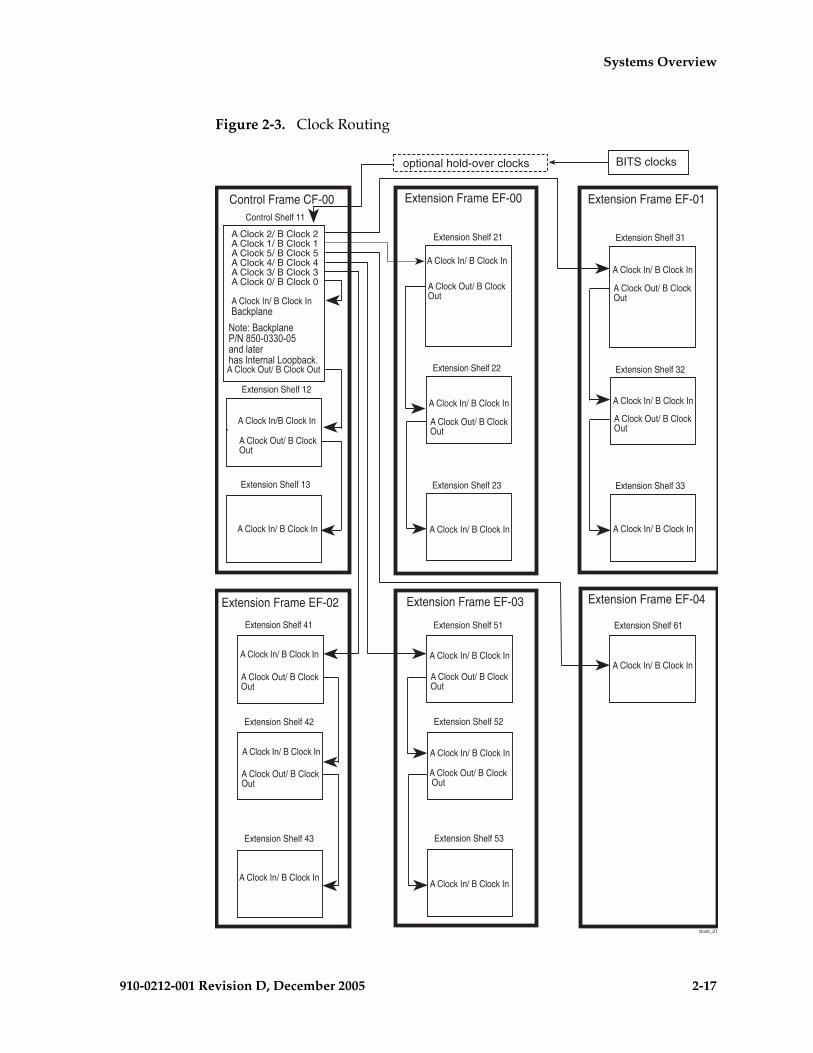
Systems Overview
910-0212-001 Revision D, December 2005 2-17
Figure 2-3. Clock Routing
Control Shelf 11
Extension Shelf 13
Extension Shelf 12
Control Frame CF-00
Extension Shelf 21
Extension Shelf 22
Extension Shelf 23
Extension Frame EF-00
A Clock Out/ B Clock Out
A Clock Out/ B ClockOut
A Clock In/B Clock In
A Clock In/ B Clock In
A Clock Out/ B ClockOut
A Clock In/ B Clock In
A Clock In/ B Clock In
A Clock Out/ B ClockOut
A Clock In/ B Clock In
A Clock 2/ B Clock 2A Clock 1/ B Clock 1A Clock 5/ B Clock 5A Clock 4/ B Clock 4A Clock 3/ B Clock 3A Clock 0/ B Clock 0
A Clock In/ B Clock In��������
Extension Shelf 31
Extension Shelf 32
Extension Shelf 33
Extension Frame EF-01
A Clock In/ B Clock In
A Clock Out/ B ClockOut
A Clock In/ B Clock In
A Clock Out/ B ClockOut
A Clock In/ B Clock In
Extension Shelf 61
A Clock In/ B Clock In
Extension Shelf 51
Extension Shelf 52
Extension Shelf 53
A Clock In/ B Clock In
A Clock Out/ B ClockOut
A Clock In/ B Clock In
A Clock Out/ B Clock Out
A Clock In/ B Clock In
Extension Shelf 41
Extension Shelf 42
Extension Shelf 43
A Clock In/ B Clock In
A Clock Out/ B ClockOut
A Clock In/ B Clock In
A Clock Out/ B ClockOut
A Clock In/ B Clock In
Extension Frame EF-02 Extension Frame EF-03 Extension Frame EF-04
optional hold-over clocks BITS clocks
clock_21
�� ����������������������������������������������������
2-18 910-0212-001 Revision D, December 2005
Systems Overview
High-Speed Master Timing
The EAGLE 5 SAS STP can be configured with high-speed master timing capabilities. High-speed master timing allows synchronization of LIM cards at E1 or T1 rates. For more information about installing or upgrading to high-speed timing see the section on Master Timing in the “NSD Installation Manual”.
Time Slot Counter Synchronization
Time Slot Counter Synchronization (TSC) Synchronization, an option for EAGLE 5 SAS STP systems in release 28.0 and later, allows all cards in the system that contain a Time Slot Counter (TSC) to synchronize with one another. The ability to have synchronized timing between cards is used in applications such as system wide message time stamping. “Time Slot Counter Synchronization” on page 3-55.
Embedded Operations Applications Processor
The Embedded Operation Support System Applications Processor (EOAP) is hosted in an assembly mounted in a dedicated OAP Frame (OAPF). The OAP and GR-376 applications run on the EOAP host assembly. More than one EOAP host shelf can be mounted in each OAPF. Each EOAP host shelf contains cards provisioned to support one or two OAP systems. The
OAP application translates and converts higher layer protocols into asynchronous serial communications. The OAP provides translation and async/X.25 conversion as part of the optional Signaling and Engineering Administration System (SEAS) interface for the EAGLE 5 SAS STP system. The EOAP can also be used to process input from he optional Local Service Management System (LSMS) (see Figure 2-4, “EOAP Hosts in an EAGLE 5 SAS STP System,” on page 2-19). An EOAP host shelf communicates with the EAGLE 5 SAS STP system control shelf through a serial interface port. The EOAP host replaces the older TMOAP assembly which is obsolete in the field but still supported by Tekelec.
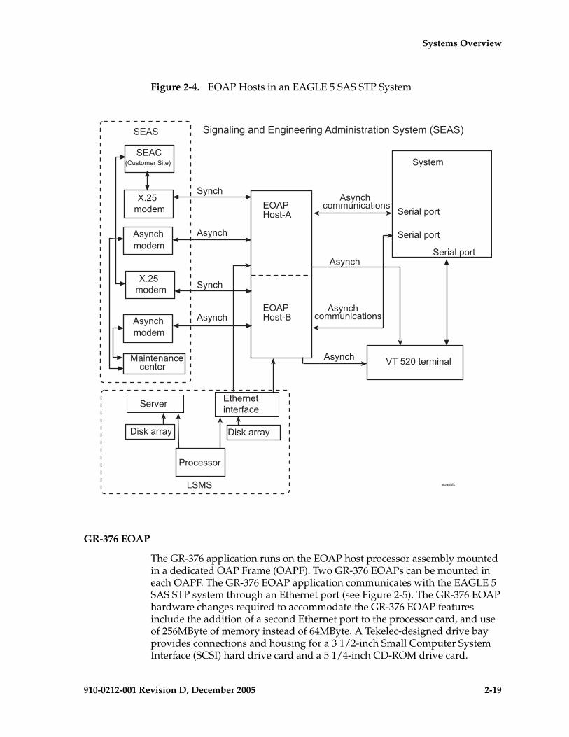
Systems Overview
910-0212-001 Revision D, December 2005 2-19
Figure 2-4. EOAP Hosts in an EAGLE 5 SAS STP System
GR-376 EOAP
The GR-376 application runs on the EOAP host processor assembly mounted in a dedicated OAP Frame (OAPF). Two GR-376 EOAPs can be mounted in each OAPF. The GR-376 EOAP application communicates with the EAGLE 5 SAS STP system through an Ethernet port (see Figure 2-5). The GR-376 EOAP hardware changes required to accommodate the GR-376 EOAP features include the addition of a second Ethernet port to the processor card, and use of 256MByte of memory instead of 64MByte. A Tekelec-designed drive bay provides connections and housing for a 3 1/2-inch Small Computer System Interface (SCSI) hard drive card and a 5 1/4-inch CD-ROM drive card.
�'��(�����
�'��(�����
�)����
�����*���
�����*���
�����*���
+�,-.�������
��)�����������������
��)�����������������
����
�������)���
����
����
�������)���
/0-,�����
/0-,�����
�����������������
���!��
#��$����) #��$����)
���������
���*"$
�������������1���
��2����2�����2�������2���������������)����3����4
��)���
��)���
��)���
��)���
�)���
�)���
3������������4

2-20 910-0212-001 Revision D, December 2005
Systems Overview
Figure 2-5. GR-376 EOAP in an EAGLE 5 SAS STP System
Integrated Sentinel
The Integrated Sentinel product provides monitoring capabilities for up to 1024 Signaling System 7 (SS7) links. Integrated Sentinel includes network surveillance capabilities and fault-management functions. Integrated Sentinel features a call detail record (CDR) generation system that uses raw network traffic on the links to generate CDR data for use in various business intelligence applications.
Figure 2-6 shows a block diagram of a SS7 monitoring network incorporating the Integrated Sentinel.
The Integrated Sentinel monitors EAGLE 5 SAS STP links internally to eliminate hardware connections such as cabling, bridge amplifiers, and patch panels. The Integrated Sentinel can receive all acknowledged message signal units (MSU) as well as other important information from the EAGLE 5 SAS STP.
Shelf
DCM Enet
Serial port
DCM Enet
VT 520 terminal
GR-376100 Base T
gr376 blk dia
Asynch
Asynch
GR-376
To LAN To LAN
100 Base T

Systems Overview
910-0212-001 Revision D, December 2005 2-21
Figure 2-6. Integrated Sentinel Block Diagram
In the EAGLE 5 SAS STP, beginning with EAGLE release 28.0, Sentinel Transport Cards (STC) can interface to the LIM cards on the IMT bus as a private LAN subnet. The STCs transfer the information collected from the LIMs by ethernet links to the Extended Services platform (ESP) of the Integrated Sentinel. Refer to “Sentinel Transport Card (EAGLE 5 SAS STP 28.0 and Later)” on page 2-14 for more information about STCs. Prior to Integrated Sentinel release 8.0 physical connections were required on the signalling links to collect this information.
LIM
ESP
LIM
GPSM-II
STC
other ESP's
MPL
STC
STP
ESP ESP
ESP ESP
STC
STC
LAN Switch
LAN SwitchIMT Bu s
TA C
TrafficDatabaseServer(TDS)
Customer Ethernet WAN
i2000 shelves
i3000 shelves
Yellow Network Links
MRV ConsoleServer
BlueNetwork
YellowNetwork
Sentinel ESPSubsystemFirst Frame
BaseSentinelServer(BSS)
DataGatewa yServe r(DGS)
SentinelAlarm sManagementServer(SAMS)
Blue Network Links
EAGLE
SS7
Link
s
Customer Terminal
Telco Line
2-22 910-0212-001 Revision D, December 2005
Systems Overview
After processing in the ESP subsystem, the monitored link information is forwarded through isolation routers to Sentinel servers. Refer to “Integrated Sentinel (ESP Frame Side)” on page 2-23 for more information about the ESP subsystem.
Integrated Sentinel on the EAGLE 5 SAS STP Side
To implement the Integrated Sentinel solution on the EAGLE 5 SAS STP side, the following hardware and software is required:
• Installation of HMUX or HIPR cards in all shelves
• Activation of HMUX Group Ticket Voucher (TVG)
• Upgrade to Sentinel release 8.1 and EAGLE Release 28.2 or later
• GPSM-II cards in OAM slots (1113 and 1115) of the control shelf
• Installation of two TDM boards (P/N 870-0774-10 and later)
• Installation of Sentinel Transport Cards (STC) in the EAGLE 5 SAS STP
• Activation of the Time Slot Counter (TSC) Synchronization feature
• Activation of the Integrated Sentinel feature
• Activation of the MSU copy feature
NOTE: Beginning with EAGLE STP Software release 30.0 all IPMX cards must be replaced by High-Speed Multiplexer (HMUX) cards (P/N 870-1965-01), all MCAP cards must be replaced by GPSM-II cards (P/N 870-2360-01), and Terminal Disk Module cards must be P/N 870-0774-10 or later. Beginning with EAGLE STP software release 33.0, IPMX cards must be replaced by either HMUX cards or High-Speed IMT Router Cards (P/N 870-2574-01). HMUX, HIPR, and GPSM-II cards are installed at the factory or by Tekelec Technical Support and are not installed by customers.
Sentinel Transport Cards
The Sentinel Transport Card (STC) is a DCM card with a new generic program load (GPL). EAGLE 5 SAS STP release 28.0 STCs are based on the dual-slot DCM card. For more information about DCM cards see the section “Database Communications Module and Database Service Module” on page 3-77 of this manual. The STC functions as an IP router between the IMT bus internal to the EAGLE 5 SAS and the ethernet networks used to communicate with the ESP servers.

Systems Overview
910-0212-001 Revision D, December 2005 2-23
Time-Slot Counter Synchronization
Time Slot Counter (TSC) Synchronization is an option for the EAGLE 5 SAS that will allow all cards in the system, which contain a Time Slot Counter, to synchronize with one another. The ability to have synchronized timing between cards is used in applications such as system wide message time stamping.
Integrated Sentinel (ESP Frame Side)
The Integrated Sentinel product provides monitoring capabilities for up to 1024 Signaling System 7 (SS7) links. Integrated Sentinel is a complete network monitoring and diagnostic system that gives service providers total visibility of and access to their SS7 networks. Integrated Sentinel features a call detail record (CDR) generation system that uses raw network traffic to generate CDR data for use in various business intelligence applications.
Beginning with EAGLE release 28.0 and Integrated Sentinel release 8.0 no cables and patch panels are required to interface with the SS7 networks. The integrated Sentinel solution monitors EAGLE 5 SAS STP links internally to eliminate hardware connections such as cabling, bridge amplifiers, and patch panels. The integrated configuration enables Integrated Sentinel to receive all acknowledged message signal units (MSU) as well as other important information from the EAGLE 5 SAS signaling platform. Refer to “Integrated Sentinel on the EAGLE 5 SAS STP Side” on page 2-22, for information about the components in the EAGLE 5 SAS STP.
Extended Services Platform
The Extended Services Platform (ESP) is the Integrated Sentinel software bundle and the required software platform that provides the interface to the Integrated Sentinel monitoring system. One Netra 120 or Tekelec 1000 Applications Server running the ESP application is referred to as an ESP server. All ESP servers located at one EAGLE 5 SAS location are an ESP subsystem. Each ESP server is considered a separate processing element with respect to communications to the downstream Sentinel servers and therefore needs its own IP address. As shown in Figure 2-6 on page 2-21, a single demarcation point is provided for the Customer's network at the ESP frame's ethernet switch.
For more information about Sentinel products and a detailed explanation of the ESP frame see Chapter 5, Hardware Descriptions — Sentinel Products, in this manual.

2-24 910-0212-001 Revision D, December 2005
Systems Overview
The Integrated Sentinel ESP subsystem interfaces to the monitored links in the EAGLE 5 SAS STP through ethernet connections to the Sentinel Transport Cards (STC) located in the EAGLE 5 SAS STP frame. See the section “Sentinel Transport Card” on page 3-86 for information about STCs. In the EAGLE 5 SAS STP the information being copied from LIM cards and sent to the ESP subassembly is transported by TCP/IP using a custom proprietary protocol called EAGLE Monitor Protocol (EMP).
OEM-Based Products and Elements
Original Equipment Manufacturer (OEM)-based products are configured in standard size frames and are NEBS compliant. Each OEM-based product provides the capacity required to deliver particular applications or services. OEM-based products, based on scalable common hardware elements, can be easily upgraded to the next higher-capacity system.
ASi 4000 SCP
The ASi 4000 SCP system provides application database services to the SS7 network. The services are in the form of queries from Service Switch Point (SSP) nodes and responses from the ASi 4000 SCP. ASi 4000 SCP service responses are sent on the same link messages are received on. Mated ASi 4000 SCPs are normally assigned different point codes but could be assigned the same point code in a network.
Multi-Platform Server (MPS) Systems
The MPS system can be configured as an EAGLE Local Number Portability (LNP) Application Processor (ELAP) or EAGLE Provisioning Application Processor (EPAP) server.
The MPS provides an interface between the customer provisioning network and the EAGLE 5 SAS STP DSM cards. As the customer’s data is updated, the MPS stores the data and updates the DSM cards. An MPS is usually co-located with an EAGLE 5 SAS STP. If you need to install an MPS at a distance from the EAGLE 5 SAS, contact “ Tekelec Customer Care Center” for assistance.
MPS running the EAGLE Provisioning Application Processor (EPAP) software supports the GSM Flexible Numbering (G-Flex), GSM Mobile Number Portability (G-Port), and INAP-based Number Portability (INP) features
These features allow a subscriber to change location, service provider, or service while keeping the same directory number and ensures that subscribers receive the same freedom of choice for local service as they do with long-distance service providers.

Systems Overview
910-0212-001 Revision D, December 2005 2-25
MPS running the EAGLE LNP Application Processor (ELAP) software supports the LNP 48 Million Numbers Feature. The Local Number Portability (LNP) 48 Million Numbers feature increases the number of provisionable telephone numbers (TNs) from 18 million to 48 million. The LNP 48 Million Numbers feature also relocates the LNP database from the OAM (Operation Administration and Maintenance) to the MPS.
Operations Support System Applications Processor
The Operations Support System Applications Processor (OAP) (EAGLE 5 SAS STP only) is an application running on a Texas Micro (TMOAP) host processor assembly mounted in a dedicated OAP Frame (OAPF). Two TMOAP host processor assemblies can be mounted in each OAPF. The OAP application translates and converts higher layer protocols into asynchronous serial communications. The OAP provides translation and async/X.25 conversion as part of the optional Signaling and Engineering Administration System (SEAS) interface for the EAGLE 5 SAS STP system. The OAP also processes input from the optional Local Service Management System (LSMS) (see Figure 2-7, “OAPs in an EAGLE 5 SAS STP System,” on page 2-26). The TMOAP host processor is obsolete in the field, for information see the section “Embedded Operations Applications Processor” on page 2-18. The OAP application also runs on the EOAP platform.

2-26 910-0212-001 Revision D, December 2005
Systems Overview
Figure 2-7. OAPs in an EAGLE 5 SAS STP System
AXi Systems
AXi Release 1.0 systems are OEM-based service solutions mounted in Tekelec frames. These systems provide network application services to customers and are configured for interoperability with AXi release 4.0 and other systems. The AXi is a full featured, scalable, high-performance media gateway controller that provides traditional and enhanced voice services over ATM or IP networks. For more information about AXi systems see the VXi Media Gateway Controller Release 4.0 Hardware and Installation Manual.
Control Shelf
Serial port
Serial port
Serial port
VT 520 terminal
OAP
OAP
Asynchcommunications
Asynchcommunications
LSMS
modemAsynch
SEAS
SEAC
modemAsynch
X.25modem
X.25modem
Maintenancecenter
Server
Disk array
Processor
oapblk3
Ethernetinterface
Signaling and Engineering Administration System (SEAS)
Asynch
Asynch
Asynch
Asynch
Synch
Synch
Disk array

Systems Overview
910-0212-001 Revision D, December 2005 2-27
AXi Release 1.0 systems described in this manual are:
• AXi 500—For a detailed hardware description of this system see “VPN Systems (AXi 500)” on page 4-17.
• AXi 1000—For a detailed hardware description of this system see “Medium System (AXi 1000)” on page 4-19
• AXi 2000—For a detailed hardware description of this system see “AXi Large System (AXi 2000)” on page 4-19
NOTE: Instructions for installing, cabling and connecting power to AXi systems are in the NSD Installation Manual.
AXi Release 1.0 systems are designed and configured for maximum flexibility. Tekelec provides basic configurations using common components and standard locations. All AXi Release 1.0 systems are configured with the following common hardware components:
• Two (AXi 500) to six (AXi 1000 and AXi 2000) Sun Netra t 1400 servers. AXi Release 1.0 servers function as Application Servers (AS), Media Servers (MS) or Network Servers (NS). Depending on the server function and location configured interface cards may be different on each server. These differences are explained in detail in the section “AXi Systems” on page 4-14 of this manual.
• Two Sun st A1000 RAID Storage Systems (RAID systems are used only in conjunction with Application Servers)
• Two Telect Breaker Panels (BP) for each configured frame
• Two Cisco 2924XL LAN Switches (Not used in the VPN (AXi 500) systems)
• One Cisco 2600 Dial-in Router (Used in Net Frames only)
• One 8-Port Connector box connected to Network Server A.
NOTE: NS A is configured with an optional multi-port serial interface connected to an 8-port serial break-out box.
Figure 2-8 is an example block diagram of the signalling interconnections between various AXi servers. Communications between AXi Release 1.0 servers and to external systems is physically through CAT5 ethernet cabling. The system depicted is configured with the maximum amount of the three server types available with AXi Release 1.0 (AXi 1000 and AXi 2000 systems).

2-28 910-0212-001 Revision D, December 2005
Systems Overview
Figure 2-8. AXi Signal Connections Block Diagram
ApplicationServer A
ApplicationServer B
MediaServer 2C
MediaServer 1C
NetworkServer A
NetworkServer B
LANSwitch 1
LANSwitch 2
RAID DiskStorageSystem
SCSIInterface
SCSIInterface
To CustomerNetwork
Dial-inModem
8-PortBreakout Box
Dedicated phone Line
To ConsolePorts
RAID DiskStorageSystem
LAN A
LAN B
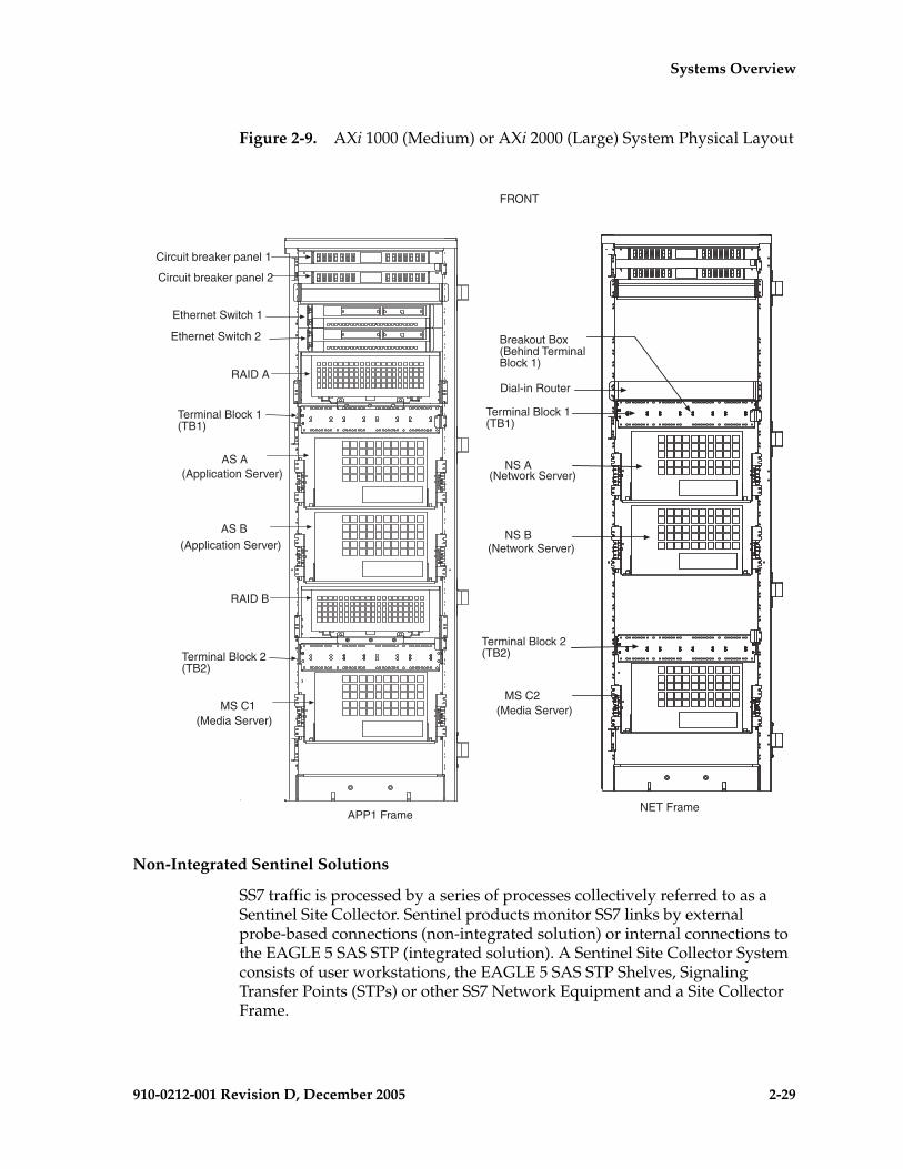
Systems Overview
910-0212-001 Revision D, December 2005 2-29
Figure 2-9. AXi 1000 (Medium) or AXi 2000 (Large) System Physical Layout
Non-Integrated Sentinel Solutions
SS7 traffic is processed by a series of processes collectively referred to as a Sentinel Site Collector. Sentinel products monitor SS7 links by external probe-based connections (non-integrated solution) or internal connections to the EAGLE 5 SAS STP (integrated solution). A Sentinel Site Collector System consists of user workstations, the EAGLE 5 SAS STP Shelves, Signaling Transfer Points (STPs) or other SS7 Network Equipment and a Site Collector Frame.
FRONT
Circuit breaker panel 1
Circuit breaker panel 2
Ethernet Switch 1
Ethernet Switch 2
RAID A
Terminal Block 1(TB1)
AS A
AS B
RAID B
Terminal Block 2(TB2)
MS C1
APP1 Frame
(Application Server)
(Media Server)
NET Frame
Terminal Block 1(TB1)
NS A
NS B
MS C2
Dial-in Router
Breakout Box(Behind TerminalBlock 1)
(Application Server)
(Network Server)
(Network Server)
(Media Server)
Terminal Block 2(TB2)

2-30 910-0212-001 Revision D, December 2005
Systems Overview
For more information about Non-Integrated Sentinel Frames see Chapter 5, Hardware Descriptions — Sentinel Products in this manual.
Components of OEM-Based Products
OEM-Based Servers
OEM-based products use Commercial Off-The-Shelf (COTS) servers, network elements, and peripheral components. Server hosts provide processing power and database storage capacity to deliver a scalable range of application specific services. Components can be configured redundantly to provide a high level of reliability in processing applications. OEM-based Product servers currently being used are:
• Sun Netra t 1400 servers (Used in the ASi 4000 SCP, MPS, VXi MGC and AXi systems)
• Sun Netra t1 100 servers (Used as optional Session Initiation Protocol (SIP) Proxy Servers in VXi MGC 3.0 systems)
• Sun Netra T1 DC200 servers (Used as Extended Services Platform (ESP) servers in the Integrated Sentinel systems).
OEM-based product capabilities are defined by specific application requirements. Optional processing components that provide application specific services can be integrated into OEM-based systems.
OEM-Based Network Elements
OEM-based products are configured as frame-mounted Local Area Networks (LAN) using Commercial Off-The-Shelf (COTS) routers, hubs, and switches. Typically OEM-based products are configured in redundant LANs with isolation and dial-up access IP links to customers networks.
Network components are typically configured in redundant pairs with dual power supply systems for reliability. Network components can include:
• Routers
• Hubs
• Ethernet Switches
• Application Servers
• Optional components

Systems Overview
910-0212-001 Revision D, December 2005 2-31
OEM-Based Peripheral Components
OEM-based products use COTS peripheral components to support the server and network elements. Peripheral components can include:
• Breaker panels
• Workstations
• Terminals
• Switch boxes
• Break-out boxes

2-32 910-0212-001 Revision D, December 2005
Systems Overview

910-0212-001 Revision D, December 2005 3-1
3
Hardware Descriptions —EAGLE/IP7 SG-Based Products
Introduction ......................................................................................................3–3
Hardware Baselines...................................................................................3–3
Frames................................................................................................................3–3
Extension Frame ........................................................................................3–9
Miscellaneous Frame...............................................................................3–14
OAP Frame ...............................................................................................3–16
Control Frame ..........................................................................................3–18
Control Shelf Backplanes........................................................................3–21
Extension Shelf.........................................................................................3–28
Extension Shelf Backplanes....................................................................3–31
Modules ...........................................................................................................3–36
High Speed IMT Router .........................................................................3–38
High-Speed Multiplexer Card ...............................................................3–43
Maintenance Disk and Alarm Card ......................................................3–46
Terminal Disk Module ............................................................................3–50
Time Slot Counter Synchronization......................................................3–55
Link Interface Modules...........................................................................3–56
High-Capacity Application Processor-Based LIMs............................3–69
Database Communications Module and Database Service Module3–77

3-2 910-0212-001 Revision D, December 2005
Hardware Descriptions — EAGLE/IP7 SG-Based Products
Database Service Module....................................................................... 3–79
Double-Slot EDCM (IP7 SG 4.0) ............................................................ 3–81
Single-Slot EDCM and EDCM-A (IP7 SG 5.0 and later) .................... 3–83
Sentinel Transport Card ......................................................................... 3–86
General Purpose Service Module ......................................................... 3–87
Measurements Collection and Polling Module .................................. 3–87
Application Communications Module ................................................ 3–94
Translation Service Module ................................................................. 3–100
E1 Interface Backplane Module .......................................................... 3–104
High-Capacity Multichannel Interface Module ............................... 3–113
Air Management Card ................................................................................ 3–119
Fuse and Alarm Panels ............................................................................... 3–121
Fuse and Alarm Panel (P/N 870-0243-08)......................................... 3–127
Fuse and Alarm Panel (P/N 870-0243-09)......................................... 3–129
Fuse and Alarm Panel (P/N 870-1606-xx/870-2320-xx) ................. 3–132
Label Kit for Fuse and Alarm Panel (P/N 870-1606-xx/870-2320-xx)3–137
Fuse Assignments ................................................................................. 3–138
Holdover Clock............................................................................................ 3–141
Maintenance Interface System Card................................................... 3–143
Critical Status Indicators Card ............................................................ 3–145
Stratum-3 Card ...................................................................................... 3–145
TOCA and TOLA Cards....................................................................... 3–146
MCA Card .............................................................................................. 3–146
Operations Support System Application Processor (OAP)................... 3–148
Embedded OAP (EOAP)...................................................................... 3–150
GR-376 EOAP ........................................................................................ 3–153

Hardware Descriptions — EAGLE/IP7
910-0212-001 Revision D, December 2005 3-3
Introduction
This chapter provides detailed descriptions of the various hardware Signal Transfer Points (STP), EAGLE 5 SAS STP, IP7 Secure Gateway (SG) systems, and EOAP/GR-376 systems. This chapter is designed, along with Chapter 2, to aid personnel in configuration, planning, and replacing components in the systems.
This chapter contains detailed descriptions of the frames, shelves, modules, and power distribution in the systems. The EAGLE-based products use many common components. Components that are not common to all EAGLE-based products are noted in the appropriate places.
This manual is intended for all personnel associated with this system. The personnel must have a thorough knowledge of telecommunication specifications and procedures.
Hardware Baselines
Appendix A, Hardware Baselines, contains a complete listing of the hardware available for each software release. The appendix lists configurable modules arranged in alphabetical order indexed to system software releases. For example, all hardware available for IP7 release 5.0 will have a bold X where the hardware module row crosses the IP7 release 5.0 column.
Frames
The system uses standard 7-foot high, 26-inch wide frames (outside dimension). These floor mounted frames are constructed from channel steel and painted with electrostatic powder. Depending on the configuration, the system uses from one to four frames to accommodate a maximum of 1024 SS7 signaling links.
NOTE 1: A heavy-duty frame with the capability to support the greater weight of COTS equipment is shipped with all new systems. The generic frame is no longer being shipped but is supported in the documentation.
NOTE 2: With the large system feature, depending on configuration, the system can accommodate up to 1024 links. The large system feature applies to the EAGLE 5 SAS STP systems only.
Additional frames may be required for optional items, such as: Operations Support System Application Processors (OAP) or Embedded OAP (EOAP) which are configured in OAP frames (OAPF). Cross-connect panels, spare card storage, modems, and holdover clocks are configured in Miscellaneous Frames (MF).
3-4 910-0212-001 Revision D, December 2005
Hardware Descriptions — EAGLE/IP7 SG-Based Products
The EOAP is a self-contained processor assembly with a cooling fan assembly. When OAPs are mentioned throughout this document Embedded OAPs may be implied.
The system can use four types of frames:
• Control Frame (CF)
• Extension Frame (EF)
• Miscellaneous Frame (MF)
• Operations Support System Application Processor Frame (OAPF)
Figure 3-1 on page 3-5 shows a system with a Control Frame (CF-00) and two Extension Frames (EF-00 and EF-01).

Hardware Descriptions — EAGLE/IP7
910-0212-001 Revision D, December 2005 3-5
Figure 3-1. Frames
Lamp indicators can be mounted on either side of the row of frames on the end panels (refer to Figure 3-2 on page 3-6), which show three levels of alarm conditions:
• Critical
• Major
• Minor
E 30 frames w LABELS
CF-00 EF-00
EF-01
11
12
13
21
22
23
31
32
33

3-6 910-0212-001 Revision D, December 2005
Hardware Descriptions — EAGLE/IP7 SG-Based Products
Figure 3-2. Frame End Panel with Lamp Indicators
The doors on the front of each frame provide electromagnetic interference shielding and lock in place with a screw lock. Mounted on the inside of the doors are card locators, used to record the location of each card in a shelf and important data regarding the application that each card provides. The shelf backplanes are protected at the rear of the frame by removable transparent Plexiglas panels.
The following lists the part numbers for the panels for the frames:
• P/N 840-0064-01 End row panel, full depth, standard frame, NTW.• P/N 840-0089-01 End row panel, full depth, heavy-duty NTW. • P/N 870-2238-01 Extended panel, alarm side, NEBS NTW. • P/N 870-2278-01 Full depth alarm side panel, heavy-duty frame, NTW.
E30 fr
ame p
anel
CRIT
MAJ
MIN
Handle
CriticalMajorMinor

Hardware Descriptions — EAGLE/IP7
910-0212-001 Revision D, December 2005 3-7
A Fuse and Alarm Panel (FAP), located at the top of each frame, distributes –48VDC to all the shelves in the frame. Fuses are located on the front of the fuse and alarm panel. For more information on the fuse and alarm panel (refer to “Fuse and Alarm Panels” on page 3-121).
The numbering of the shelves, with the shelf identification backplane wiring, circuit card location, and with the Inter-processor Message Transport (IMT) address in small print at the bottom of the faceplates is shown in Figure 3-3. The HMUX or HIPR card provides Inter-processor Message Transport (IMT) bus continuity for all cards connected to the IMT bus.
NOTE: Beginning with EAGLE STP Software release 30.0 all IPMX cards must be replaced by High-Speed Multiplexer (HMUX) cards (P/N 870-1965-01. Beginning with EAGLE STP software release 33.0, IPMX cards must be replaced by either HMUX cards or High-Speed IMT Router Cards (P/N 870-2574-01). HMUX and HIPR cards are installed at the factory or by Tekelec Technical Support and are not installed by customers.

3-8 910-0212-001 Revision D, December 2005
Hardware Descriptions — EAGLE/IP7 SG-Based Products
Figure 3-3. Control Frame CF-00 Numbering Plan
GRD
SHELFID
BIT
GRD
00010203
SHELFID
BIT
GRD
00010203
1202
1203
1204
1205
1206
1201
1207
1208
1209
1210
1211
1212
1213
1214
1215
1216
1217
1218
Extension Shelf 12
1302
1303
1304
1305
1306
1301
1307
1308
1309
1310
1311
1312
1313
1314
1315
1316
1317
1318
Extension Shelf 13
00 01 03 04 05 06 0702 08 09 0A 0B 0C 0D 0E 0F
11-2-3
��������
� ����������
���
���
��������
� ����������
���
���
DIP switchidentification
Wire wrapidentification
DIP switchidentification
Wire wrapidentification
18 19 1A 1B 1C 1D 1E 1F10 11 13 14 15 16 1712
Cardlocationnumbers
IMTaddresses
Cardlocationnumbers
IMTaddresses
02 and Earlier03 and Later
BackPlaneP/N 850-0356-
Extension Shelf
1102
1103
1104
1105
1106
1101
1107
1108
1109
1110
1112
1113
1114
1116
1117
MDALMCAPA
TDMA
Control Shelf 11
1115
1111
MCAPB
TDMB
F8 F9F0 F1 F2 F3 F4 F5 F6 F7 FBFA
These locations arepaired entities
1118
Cardlocationnumbers
IMTaddresses
Shelf ID not usedon Control Shelf
SHELFID
BIT 00010203

Hardware Descriptions — EAGLE/IP7
910-0212-001 Revision D, December 2005 3-9
Extension Frame
The Extension Frame (EF) accommodates up to three extension shelves, each shelf is capable of supporting up to 16 Link Interface Modules (LIMs), Multi-Port LIMs (MPLs), E1/T1 MIMs, Translation Service Modules (TSMs), or Applique Communication Modules (ACMs), or Single-slot Enhanced Database Communications Modules, in any combination.
The EAGLE 5 SAS STP systems are delivered with customer-specific locations for the Database Communications Module (DCM) cards and DCMX cards. DCM and DCMX cards must be inserted into odd numbered slots in EAGLE 5 SAS STP systems.
NOTE: DCM cards can be configured in all EAGLE 5 SAS STP or IP7 SG systems. Double-slot EDCM cards can be configured in IP7 SG release 4.0 and later. Single-slot EDCM and EDCM-A cards can be configured in IP7 SG release 5.0 and later. EDCM and EDCM-A cards can be configured in EAGLE 5 SAS STP systems in release 28.0 and later.
The system can have up to five Extension Frames, EF-00 to EF-04. EF-04 supports only one extension shelf. The numbering of the shelves is shown, with the shelf identification backplane wiring, circuit card location, and the Inter-processor Message Transport (IMT) address in small print at the bottom of the faceplate. The numbering of the card locations on the extension frames and the IMT address is shown in Figure 3-4 on page 3-10 through Figure 3-7 on page 3-13.
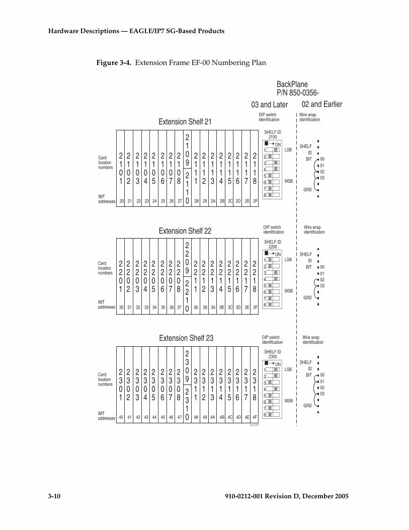
3-10 910-0212-001 Revision D, December 2005
Hardware Descriptions — EAGLE/IP7 SG-Based Products
Figure 3-4. Extension Frame EF-00 Numbering Plan
SHELFID
BIT
GRD
00010203
SHELFID
BIT
GRD
00010203
SHELFID
BIT
GRD
00010203
2102
2103
2104
2105
2106
2101
2107
2108
2109
2110
2111
2112
2113
2114
2115
2116
2117
2118
20 21 22 23 24 25 26 27
Extension Shelf 21
2202
2203
2204
2205
2206
2201
2207
2208
2209
2210
2211
2212
2213
2214
2215
2216
2217
2218
30 31 33 34 35 36 37
Extension Shelf 22
2302
2303
2304
2305
2306
2301
2307
2308
2309
2310
2311
2312
2313
2314
2315
2316
2317
2318
40 41 43 44 45 46 47
Extension Shelf 23
32
42
38 39 3A 3B 3C 3D 3E 3F
48 49 4A 4B 4C 4D 4E 4F
28 29 2A 2B 2C 2D 2E 2F
sh 21-2-3
��������
� ����������
���
���
��������
� ����������
���
���
��������
� ����������
���
���
DIP switchidentification
Wire wrapidentification
DIP switchidentification
Wire wrapidentification
DIP switchidentification
Wire wrapidentification
Cardlocationnumbers
IMTaddresses
Cardlocationnumbers
IMTaddresses
Cardlocationnumbers
IMTaddresses
02 and Earlier03 and Later
BackPlaneP/N 850-0356-
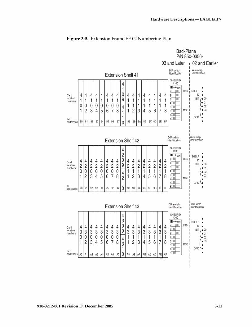
Hardware Descriptions — EAGLE/IP7
910-0212-001 Revision D, December 2005 3-11
Figure 3-5. Extension Frame EF-02 Numbering Plan
SHELFID
BIT
GRD
00010203
SHELFID
BIT
GRD
00010203
SHELFID
BIT
GRD
00010203
4102
4103
4104
4105
4106
4101
4107
4108
4109
4110
4111
4112
4113
4114
4115
4116
4117
4118
80 81 82 83 84 85 86 87
Extension Shelf 41
4202
4203
4204
4205
4206
4201
4207
4208
4209
4210
4211
4212
4213
4214
4215
4216
4217
4218
90 91 93 94 95 96 97
Extension Shelf 42
4302
4303
4304
4305
4306
4301
4307
4308
4309
4310
4311
4312
4313
4314
4315
4316
4317
4318
A0 A1 A3 A4 A5 A6 A7
Extension Shelf 43
92
A2
98 99 9A 9B 9C 9D 9E 9F
A8 A9 AA AB AC AD AE AF
88 89 8A 8B 8C 8D 8E 8F
sh 41-2-3
ON12345678
SHELF ID4100
LSB
MSB
ON12345678
SHELF ID4200
LSB
MSB
ON12345678
SHELF ID4300
LSB
MSB
DIP switchidentification
Wire wrapidentification
DIP switchidentification
Wire wrapidentification
DIP switchidentification
Wire wrapidentification
Cardlocationnumbers
IMTaddresses
Cardlocationnumbers
IMTaddresses
Cardlocationnumbers
IMTaddresses
03 and Later
BackPlaneP/N 850-0356-
02 and Earlier
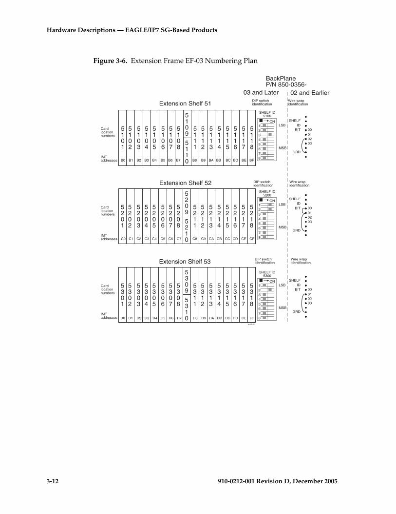
3-12 910-0212-001 Revision D, December 2005
Hardware Descriptions — EAGLE/IP7 SG-Based Products
Figure 3-6. Extension Frame EF-03 Numbering Plan
SHELFID
BIT
GRD
00010203
SHELFID
BIT
GRD
00010203
SHELFID
BIT
GRD
00010203
5102
5103
5104
5105
5106
5101
5107
5108
5109
5110
5111
5112
5113
5114
5115
5116
5117
5118
B0 B1 B2 B3 B4 B5 B6 B7
Extension Shelf 51
5202
5203
5204
5205
5206
5201
5207
5208
5209
5210
5211
5212
5213
5214
5215
5216
5217
5218
C0 C1 C3 C4 C5 C6 C7
Extension Shelf 52
5302
5303
5304
5305
5306
5301
5307
5308
5309
5310
5311
5312
5313
5314
5315
5316
5317
5318
D0 D1 D3 D4 D5 D6 D7
Extension Shelf 53
C2
D2
C8 C9 CA CB CC CD CE CF
D8 D9 DA DB DC DD DE DF
B8 B9 BA BB BC BD BE BF
sh 51-2-3
ON12345678
SHELF ID5100
LSB
MSB
ON12345678
SHELF ID5200
LSB
MSB
ON12345678
SHELF ID5300
LSB
MSB
DIP switchidentification
Wire wrapidentification
DIP switchidentification
Wire wrapidentification
DIP switchidentification
Wire wrapidentification
Cardlocationnumbers
IMTaddresses
Cardlocationnumbers
IMTaddresses
Cardlocationnumbers
IMTaddresses
03 and Later
BackPlaneP/N 850-0356-
02 and Earlier

Hardware Descriptions — EAGLE/IP7
910-0212-001 Revision D, December 2005 3-13
Figure 3-7. Extension Frame EF-04 Numbering Plan
6102
6103
6104
6105
6106
6101
6107
6108
6109
6110
6111
6112
6113
6114
6115
6116
6117
6118
E0 E1 E2 E3 E4 E5 E6 E7
Extension Shelf 61
E8 E9 EA EB EC ED EE EF
sh 61
��������
� ���������
���
���
SHELFID
BIT
GRD
00010203
DIP switchidentification
Wire wrapidentification
Cardlocationnumbers
IMTaddresses
03 and Later
BackPlaneP/N 850-0356-
02 and Earlier
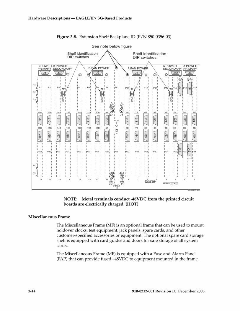
3-14 910-0212-001 Revision D, December 2005
Hardware Descriptions — EAGLE/IP7 SG-Based Products
Figure 3-8. Extension Shelf Backplane ID (P/N 850-0356-03)
NOTE: Metal terminals conduct -48VDC from the printed circuit boards are electrically charged. (HOT)
Miscellaneous Frame
The Miscellaneous Frame (MF) is an optional frame that can be used to mount holdover clocks, test equipment, jack panels, spare cards, and other customer-specified accessories or equipment. The optional spare card storage shelf is equipped with card guides and doors for safe storage of all system cards.
The Miscellaneous Frame (MF) is equipped with a Fuse and Alarm Panel (FAP) that can provide fused –48VDC to equipment mounted in the frame.
J9
J10
J11
J12
J13
J14
J15
J16
J17
J18
J19
J20
J21
J22
J23
J24
J25
J26
J27
J29
J28
J30
J31
J32
J33
J34
J35
J36
J37
J38
J39
J40
J41
J42
J1 J2 J3 J4
J5
J46
J6
J45
J7 J8
J43 J44
850-0356-03 w co
P1 P2 P3 P4 P5 P6 P7 P8 P9 P10 P11 P12 P13 P14
P34P33P32P31P30P29P28P27P26P25P24P23P22P21P20P19P18
P15 P16 P17
123456781112131415161718
10
9
1A2A3A4A5A6A7A8A11A12A13A14A15A16A 10A 9A
1B2B3B4B5B6B7B8B11B12B13B14B15B16B 10B 9B
R1
R2
R3
R4
R5
Shelf identificationDIP switches
Shelf identificationDIP switches
B POWERPRIMARY
B POWERSECONDARY
A POWERSECONDARY
A POWERPRIMARYB FAN POWER A FAN POWER
BIMTIN
BIMTOUT
IPMXA
AIMTIN
AIMTOUT
SW
1
SW
2
SW
3
SW
4
ACLK IN
ACLKOUT
See note below figure
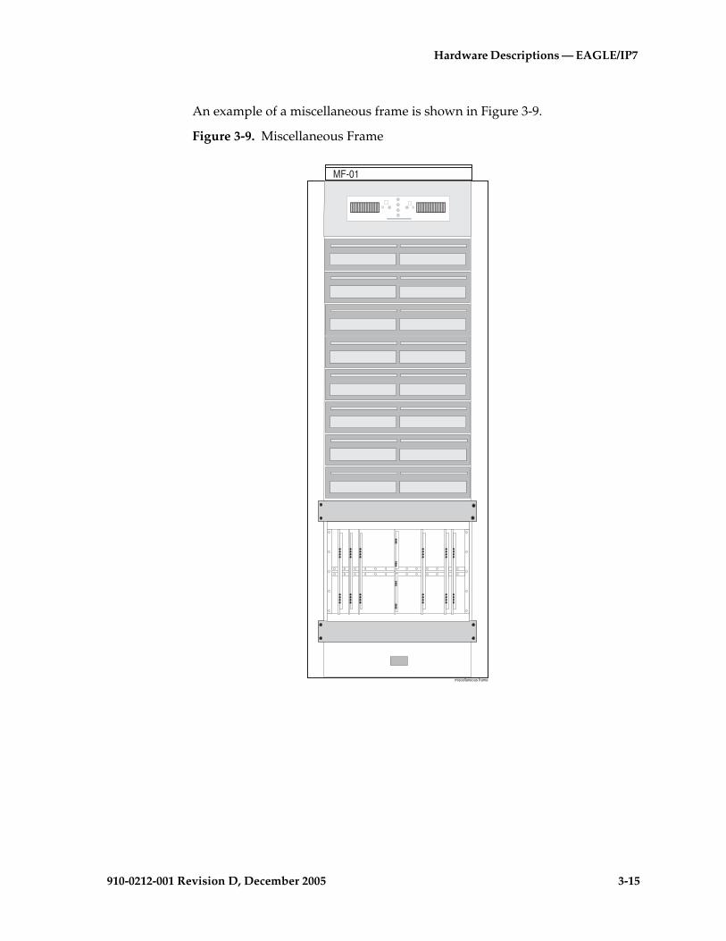
Hardware Descriptions — EAGLE/IP7
910-0212-001 Revision D, December 2005 3-15
An example of a miscellaneous frame is shown in Figure 3-9.
Figure 3-9. Miscellaneous Frame
MF-01
miscellaneous frame

3-16 910-0212-001 Revision D, December 2005
Hardware Descriptions — EAGLE/IP7 SG-Based Products
OAP Frame
The Operation Support System Application Processor Frame (OAPF) is an optional frame for mounting the processors hosting optional OAP applications or Embedded Operations Support System Applications Processors (EOAPs). This frame is typically located next to the system’s control frame, but may be customer engineered in other locations under special circumstances.
The OAPF is equipped with a Fuse and Alarm Panel (FAP), shown in Figure 3-10, that provides fused –48VDC to equipment mounted in the frame.
Figure 3-10. OAP Frame
BA
OAPF
oapfframe
Fuse andAlarm Panel
OAP front panel
OAP front panel

Hardware Descriptions — EAGLE/IP7
910-0212-001 Revision D, December 2005 3-17
Figure 3-11. OAPF Containing Embedded OAP Hosts
BA
OAPF
EOAPf
Fuse andAlarm Panel
EOAP front panel
EOAP hard drive CDROM
Fan unit
Fan switch
Grill
Cooling duct

3-18 910-0212-001 Revision D, December 2005
Hardware Descriptions — EAGLE/IP7 SG-Based Products
Control Frame
The Control Frame (CF) is the principle frame for the system. The top shelf is the control shelf, containing all the components of the Maintenance and Administration Subsystem (MAS), and up to ten additional Link Interface Modules (LIMs), Multi-Port LIMs (MPLs), E1/T1 MIMs, Integrated LIM AINF (ILAs), Translation Service Modules (TSMs), Database Communications Modules (DCMs) or Database Service Modules (DSM) (Both DCMs and DSMs require two card slots), or Application Communications Modules (ACMs).
The control frame can also contain up to two extension shelves. Each extension shelf can accommodate up to 16:
• LIMs or Integrated LIM Applique Interface (ILA) or Enhanced Integrated LIM Applique Interface (EILA) cards
• Application Communications Modules (ACM)
• Single-slot Enhanced Database Communications Modules (EDCM or EDCM-A)
Or eight:
• Database Communications Modules (DCMs) or Database Service Modules (DSM) (Both DCMs and DSMs require two card slots)
• Double-slot Enhanced Database Communications Modules (EDCM) (requires two card slots)
With the exception of DCMs and double-slot EDCMs, all cards can be inserted in any slot except for those locations dedicated to the HMUX, HIPR, MASP, and MDAL cards. In EAGLE systems and IP7 4.0 and earlier systems, DCMs and double-slot EDCMs must be placed into odd-numbered slots, and due to their width the adjoining even-numbered slot will be taken as well.
Control Shelf
The control shelf is divided into two parts. One part is used by the Maintenance and Administration Subsystem (MAS) and contains the following hardware:
• Two Terminal Disk Modules (TDMs)
NOTE: Beginning with EAGLE Release 31.6 Terminal Disk Module cards must be P/N 870-0774-15 to support Global Timing Interface (TDM-GTI).
• Two GPSM-II cards
Hardware Descriptions — EAGLE/IP7
910-0212-001 Revision D, December 2005 3-19
NOTE: Beginning with EAGLE STP Software Release 30.0 all MCAP cards must be replaced by GPSM-II cards (P/N 870-2360-01). GPSM-II cards are installed at the factory or by Tekelec Technical Support, not by the customer.
• One Maintenance Disk and Alarm card (MDAL)
Each TDM/GPSM-II pair makes up a Maintenance and Administration Subsystem Processor (MASP).
Two HIPR or HMUX (EAGLE 5 SAS STP) cards provide Inter-processor Message Transport (IMT) bus continuity for all cards connected to the IMT bus.
NOTE: HMUX and HIPR cards are installed at the factory or by Tekelec Technical Support and are not installed by customers.
The remainder of the control shelf can be occupied by up to ten of the following cards, in any combination and in any location not dedicated to an MASP pair or HIPR card:
• Integrated LIM AINF (ILA) or Enhanced Integrated LIM AINF (EILA)
• Link Interface Module (LIM)
• Multi-Port Link Interface Module (MPL)
• E1/T1 Multi-Channel Interface Module (MIM)
• Application Communications Module (ACM)
• Translation Service Module (TSM)
• Single-slot Enhanced Database Communications Module (EDCM and EDCM-A)
Database Communications Module (DCM) and Database Service Module (DSM) are only configured in available odd numbered slots, and requires two card slots.
Double-Slot Enhanced DCMs (IP7 SG 4.0 and later)
Double-Slot Enhanced DCMs, used in the IP7 SG release 5.0 and later systems, can be configured in any slot where they can physically fit. Double-Slot EDCMs require two card slots.
CAUTION: After the frame has been shipped or moved, prior to applying power, remove all cards. Reset all cards carefully to avoid possible faulty connections. All cards are hot swappable
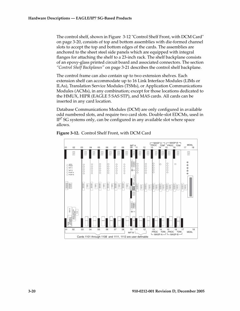
3-20 910-0212-001 Revision D, December 2005
Hardware Descriptions — EAGLE/IP7 SG-Based Products
The control shelf, shown in Figure 3-12 "Control Shelf Front, with DCM Card" on page 3-20, consists of top and bottom assemblies with die-formed channel slots to accept the top and bottom edges of the cards. The assemblies are anchored to the sheet steel side panels which are equipped with integral flanges for attaching the shelf to a 23-inch rack. The shelf backplane consists of an epoxy-glass printed circuit board and associated connectors. The section “Control Shelf Backplanes” on page 3-21 describes the control shelf backplane.
The control frame can also contain up to two extension shelves. Each extension shelf can accommodate up to 16 Link Interface Modules (LIMs or ILAs), Translation Service Modules (TSMs), or Application Communications Modules (ACMs), in any combination; except for those locations dedicated to the HMUX, HIPR (EAGLE 5 SAS STP), and MAS cards. All cards can be inserted in any card location.
Database Communications Modules (DCM) are only configured in available odd numbered slots, and require two card slots. Double-slot EDCMs, used in IP7 SG systems only, can be configured in any available slot where space allows.
Figure 3-12. Control Shelf Front, with DCM Card
IMT A
10
01 02 03 04 05 06 07 08 09 11 12 13 14 15 16 17 18
01 02 03 04 05 06 07 08 11 12 13 14 15 16 17 18
TDMTDM MDALPROC
TDMTDM MDALPROC
PROC
PROCMASP-A MASP-B
MASP A MASP-B
0 1
2 3
4 5
6 7
8 9
0123456789
RE
V X
IPM
X870-1
171-X
X
5VALARM
0 1
2 3
4 5
6 7
8 9
0123
4567
89
5VALARM
Cards 1101 through 1108 and 1111, 1112 are user definable
TEKELEC
TEKELEC TEKELEC TEKELEC TEKELEC TEKELEC TEKELEC TEKELEC TEKELECTEKELEC TEKELEC TEKELEC TEKELEC TEKELEC TEKELEC TEKELEC
0 1
2 3
4 5
6 7
8 9
0123
4567
89
DC
MA
SS
EM
BLY
012-
3456
-78
APPLPROC
IMT A
IMT B
PORT A
PORT B
CLI
I
SE
RIL
AZ
AT
ION
0123
4567
890RE
V-X
IMT B

Hardware Descriptions — EAGLE/IP7
910-0212-001 Revision D, December 2005 3-21
Control Shelf Backplanes
This section describes the control shelf backplane (P/N 850-0330-03/04) and the control shelf backplanes (P/N 850-0330-06), all can be used in EAGLE 5 SAS STP systems. Control shelf backplane (P/N 850-0330-03/04) can be used in IP7 SG systems.
NOTE 1: Control Shelf Backplane (P/N 850-0330-03/04) can be used with the HMUX and HIPR in the EAGLE 5 SAS STP system with minor modifications and the addition of adapter cable (P/N 830-0857-01). The adapter cable is not necessary for customers not wanting high speed links.
NOTE 2: Control Shelf Backplane (P/N 850-0330-05) can not be used with EAGLE Release 30.0.
NOTE 3: The clocking and fan control signals used to support extension frames 6 and 7 are eliminated in the 850-0330-06 version and later of the Control Shelf Backplane because those frames are no longer supported in the EAGLE 5 SAS STP system.
The control shelf backplane provides connectors for the system circuit cards. These connectors are four column High Density Interconnect (HDI) male headers with shrouds of varying pin quantities, depending on card position.
• EILA, ILA, LIM, MPL, E1/T1 MIM, ACM, TSM, and single-slot EDCM and EDCM-A cards can be used in slots 1, 2, 3, 4, 5, 6, 7, 8, 11, and 12.
• HMUX and HIPR (EAGLE 5 SAS STP) cards are connected in slots 9 and 10.
NOTE: Beginning with EAGLE STP Software release 30.0 all IPMX cards must be replaced by High-Speed Multiplexer (HMUX) cards (P/N 870-1965-01), all MCAP cards must be replaced by GPSM-II cards (P/N 870-2360-01), and Terminal Disk Module cards must be (P/N 870-0774-10) and later. Beginning with EAGLE STP software release 33.0, IPMX cards must be replaced by either HMUX cards or High-Speed IMT Router Cards (P/N 870-2574-01). HMUX, HIPR, and GPSM-II cards are installed at the factory or by Tekelec Technical Support and are not installed by customers.
• TDMs and TDM-GTIs are connected in slots 14 and 16.
• GPSM-II cards are connected in slots 13 and 15.
• The MDAL card is connected in slot 17 and 18.
• The DCM and DSM cards, used in EAGLE 5 SAS STP systems, are mounted only in available odd numbered slots 1, 3, 5, 7, and 11. The DCM cards and DSM cards are initially provided only in the control frame of the

3-22 910-0212-001 Revision D, December 2005
Hardware Descriptions — EAGLE/IP7 SG-Based Products
EAGLE systems but can be configured into extension shelves through contractual and maintenance agreements with Tekelec.
NOTE: Double-slot EDCMs, used in IP7 SG release 5.0 and later systems, also require two slots but are not restricted to odd slots.
The control shelf backplane provides –48VDC power and ground to all card positions. The power is distributed into two parts, A and B. Power is brought to the shelf from the Fuse and Alarm Panel (FAP) using two cables. The connectors on the control shelf backplane are DB-26 high density connectors. The power is distributed over two separate pins per power connection to handle the current load. The current capacity of the connector pins is 1.5A per pin for a total of 3A per pair. In the “Installation manual” tables list the shelf location, card type, and fuse location in the fuse and alarm panel for the control shelf backplane.
NOTE: Cards that are provisioned in redundant pairs must be on separate power buses. This provides backup processing capabilities with the loss of either the A or B power buses. All MASP, HMUX, and HIPR cards are provisioned in pairs and are redundantly powered from separate power buses.
The control shelf power connectors are designated as:
• J1 (B Power) and J4 (A Power) on control shelf backplane (P/N 850-0330-03/04)
• J1 (B Power Primary) and J2 (B Power secondary) J11 (A Power primary) and J10 (A Power Secondary) on control shelf backplane (P/N 850-0330-06).
The following Figure 3-13 "Control Shelf Backplane (P/N 850-0330-03)" on page 3-24, and Figure 3-14 "Control Shelf Backplane (P/N 850-0330-06)" on page 3-25 show the layouts for the control shelf connectors.
CAUTION: Disconnect both Input and supply sources when repairs require removal of power. This will take the system down.
NOTE 1: Control Shelf Backplane (P/N 850-0330-05) and (P/N 850-0330-06) have similar connection layouts but the names and pinouts of the connectors are different. Control Shelf Backplane (P/N 850-0330-05) can not be used with the HMUX card (EAGLE 5 SAS STP) which is an integral part of the large system feature. The Control Shelf Backplane (P/N 850-0330-05) must be replaced with (P/N 850-0330-06) or later to incorporate these features.
NOTE 2: Control Shelf Backplane (P/N 850-0330-03/04) can be used with the HMUX and HIPR in the EAGLE 5 SAS STP system with minor modifications and the addition of adapter cable (P/N 830-0857-01).

Hardware Descriptions — EAGLE/IP7
910-0212-001 Revision D, December 2005 3-23
Figures 3-13 and 3-14 depict the various control shelf backplanes. Figure 3-13 on page 3-24 is the rear connector view of control shelf backplane (P/N 850-0330-03), control shelf backplane (P/N 850-0330-04) has identical connections. Figure 3-14 on page 3-25 illustrates the control shelf backplane (P/N 850-0330-06).
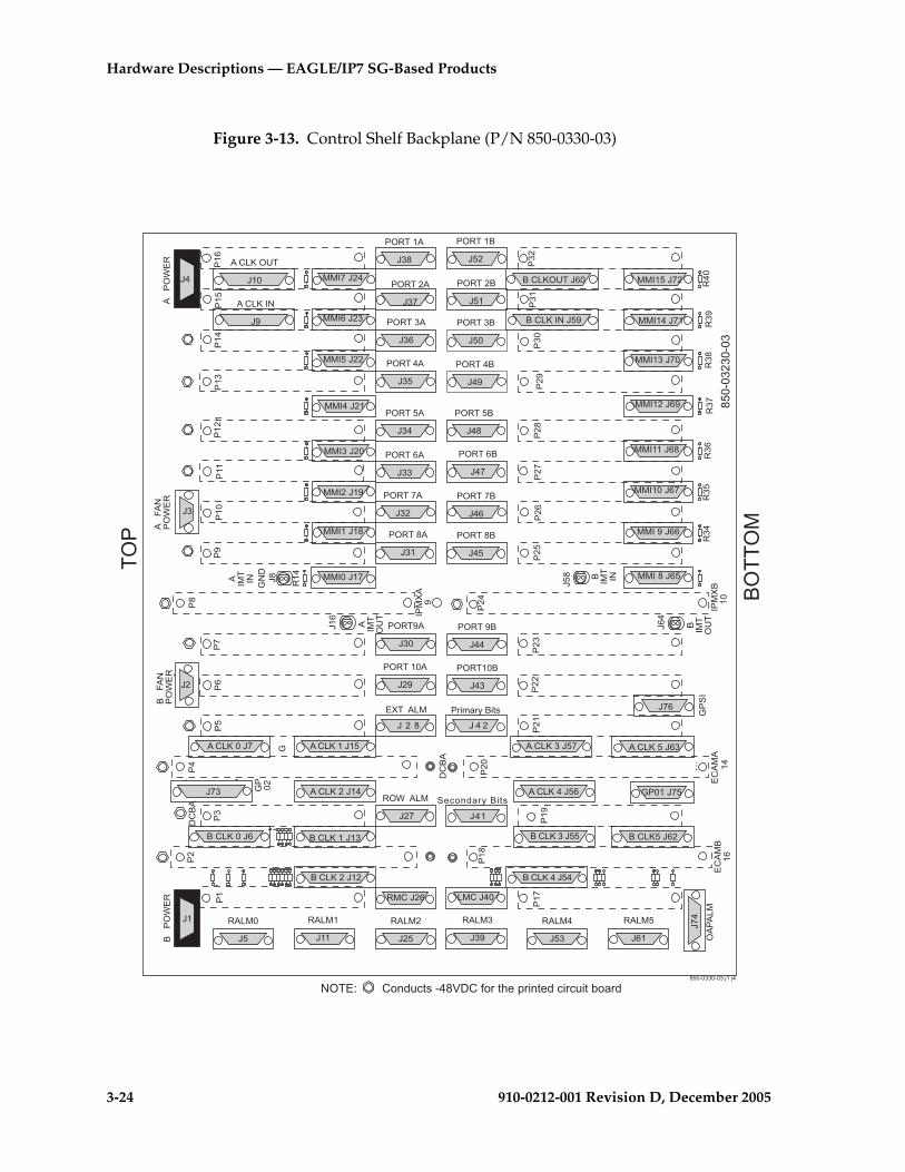
3-24 910-0212-001 Revision D, December 2005
Hardware Descriptions — EAGLE/IP7 SG-Based Products
Figure 3-13. Control Shelf Backplane (P/N 850-0330-03)
���5�6�7
���5�6�,
��8
���5,6 7
�-�
�--
�-7
�7�
�7-
6�
�9
:
�-.
��;
��
�7
��.
�<
���
��-
��7
��9
��,
�
#���
��'=�
���5�>
6<
���5'��
6�.69
#���
���5�>6,<
���5'��6 .
���576,8
���596,
���576,,
���5-6�-
���5-6�9
���5.68
���5.6
���.
6,
�%�>
�'=�
��'=�
�%�>
�'=�
����
6��
���-
6-,
���7
67<
���9
6,7
���,
6 �
���69. ��6-
689
��<
:�.�68,
'�����
�����
�
���5,6 -
68 �����
�9
:���
� ���
'��
6 9
� ���
�>
���/�
�.
6,;
�-,
�-9
79
7,
7
78
7;
7<
9.
����968�
����,68-
�-
�-8
�-;
�-<
�7.
� ���
'�� ���/�
<
� ���
�>
������)����
�' ��.�
697
��������)���� '=���
6-8
�/����
�' ��.�
6-<
�' �<�
67.
�' �<�
699
�' �;�
67�
�' �;�
69,
�' �8�
67-
�' �8�
69
�' � �
677
�' � �
698
�' �,�
679
�' �,�
69;
��� 6-7
�' �9�
67,
�' �9�
69<
�' �7�
67
�' �7�
6,.
�' �-�
678
�' �-�
6,�
�' ���
67;
�' ���
6,-:�.-
:>#
�-
�9
687
�,
�
�8
6-
67
�;
��
6;
69�
6 9 -6 - ;
6�
���596,9
;,.�.77.�.7?�?9
�'�
�'��'�
����768.
����-6 <
�����6 ;
����.6 8
���<6
���;6 ,
;,.�.7-7.�.7
>'��@ ���������9;+#�1�����*�������������"����
���,6--
���96-�
���76-.
���-6�<
����6�;
���.6�8
���86-9
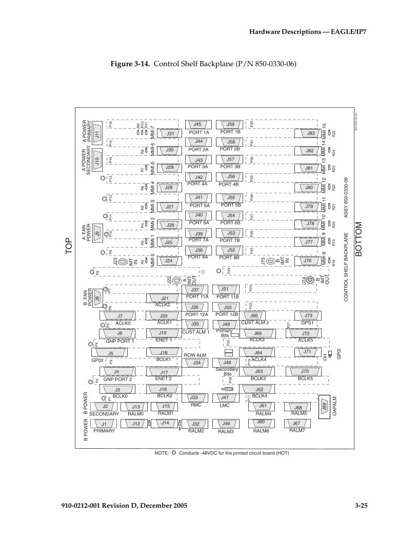
Hardware Descriptions — EAGLE/IP7
910-0212-001 Revision D, December 2005 3-25
Figure 3-14. Control Shelf Backplane (P/N 850-0330-06)
J1
J2
J3
J4
J5
J6
J7
J8J9
J10
J11
J12
J13
J14
J15
J16
J17
J18
J19
J20
J21
J22
J23 J24
J25
J26
J27
J28
J29
J30
J31
J32
J33
J34
J35
J36
J37
J38
J39
J40
J41
J42
J43
J44
J45
J46
J47
J48
J49
J50
J51
J52
J53
J54
J55
J56
J57
J58
J59
J60
J61
J62
J63
J64
J66
J67
J68 J69
J70
J71
J72
J73
J74
J75 J76
J77
J78
J79
J80
J81
J82
J83
A P
OW
ER
PR
IMA
RY
850-
0330
-06
pwr
A P
OW
ER
SE
CO
ND
AR
YB
PO
WE
RB
PO
WE
R
CO
NT
RO
L S
HE
LF B
AC
KP
LAN
EA
SS
Y 8
50-0
330-
06
A IMT
IN
A IMT
OU
T
ENET 1
ACLK2
MM
I 0M
MI 2
MM
I 1
R2
R3
R4
MM
I 3M
MI 5
MM
I 4
R5
R6
R7
MM
I 6M
MI 7
R8
R9
R10
R11
RALM7
RALM5 OA
PA
LMG
P0I
GPS1
B IMT
IN
B IMT
OU
TM
MI 8
MM
I 9M
MI 1
0M
MI 1
1M
MI 1
2M
MI 1
3M
MI 1
4
R18
R19
R20
R21
R22
MM
I 15
R23
R24
R25
ACLK5
BCLK5
CUST ALM 1
CUST ALM 2
B F
AN
PO
WE
RA
FA
NP
OW
ER
PrimaryBits
Secondary Bits
R13
P16
P15
P14
P13
P12
P11
P10
P9
P8
P7
P6
P5
P4
P3
P2
P1
P32
P31
P30
P29
P28
P27
P26
P25
P24
P23
P22
P20
P19
P18
P17
P21
ROW ALM
TO
P
BO
TT
OM
RALM6
RALM4
RALM3
LMCRMC
RALM2
RALM1
PRIMARY
SECONDARY RALM0
BCLK0
GNP PORT 2
GNP PORT 1
ACLK0 ACLK1
ACLK3
ACLK4
J65
BCLK3
PORT 1B
PORT 2B
PORT 3B
PORT 4B
PORT 5B
PORT 6B
PORT 7B
PORT 8B
PORT 1A
PORT 2A
PORT 3A
PORT 4A
PORT 5A
PORT 6A
PORT 7A
PORT 8A
PORT 11B
PORT 12B
PORT 11A
PORT 12A
GP02
BCLK2
ENET 2
BCLK1
BCLK4
NOTE: Conducts -48VDC for the printed circuit board (HOT)
3-26 910-0212-001 Revision D, December 2005
Hardware Descriptions — EAGLE/IP7 SG-Based Products
Alarm Connectors
The control shelf backplanes (P/N 850-0330-03/04 and P/N 850-0330-06) contain eight types of alarm connectors. The connectors used are the Remote Maintenance Center (RMC), the Local Maintenance Center (LMC), the Rack Alarm (RALMx), the Row Alarm (ROW ALM), the OAP Alarm (OAPALM), and the External Alarm (EXT ALM). The RMC, LMC, RALMx, OAPALM, and ROW ALM functions use DB-15 connectors, and the EXT ALM connector uses a DB-26 connector. The alarm connectors on the control shelf are designated as follows:
• Remote Maintenance Center Alarm Connector (RMC)—J26 on backplane (P/N 850-0330-03/04) or J33 on backplanes (P/N 850-0330-06) provides system alarm condition indicators to the remote maintenance center.
• Local Maintenance Center Alarm Connector (LMC)—J40 on backplane (P/N 850-0330-03/04) or J47 on backplanes (P/N 850-0330-06) provides the system’s alarm condition indicators to the local maintenance center.
• Rack Alarm Connectors (RALMx)— J5, J11, J25, J39, J53, and J61 on backplane (P/N 850-0330-03/04) or J13, J15, J32, J46,J60, J61, J67,and J68 on backplanes (P/N 850-0330-06). The output of the rack alarm connectors control the alarm condition indicators on each control or extension frame fuse and alarm panel.
• OAP Alarm Connector (OAPALM)— J74 (P/N 850-0330-03/04) or J69 on backplanes (P/N 850-0330-06). The OAP alarm connector controls the alarm condition indicators on an OAP frame.
• Row Alarm Connector (ROW ALM)— J27 on backplane (P/N 850-0330-03/04) or J34 on backplane (P/N 850-0330-06). The row alarm connector controls the alarm condition indicators on an end panel at the end of a set of the frames.
• External Alarm Connector (EXT ALM)— J28 on backplane (P/N 850-0330-03/04). This connector is also used for alarm condition inputs from an optional holdover clock.
• CUST Alarm 1— J35 on backplanes (P/N 850-0330-06). This connector is used for alarm condition inputs from an optional holdover clock or customer supplied clock source. This connector is not supported at this time.
• CUST Alarm 2— J66 on backplanes (P/N 850-0330-06). This connector provides input to the system for alarms designated by the customer. This connector is not supported at this time.
System Clock Connectors
The control shelf backplane provides system clock output to the rest of the system from the TDMs. Redundancy is accomplished by allowing TDM A and TDM B to distribute clocks independently of each other. These signals are driven to other parts of the system adhering to the RS-485 standard.
Hardware Descriptions — EAGLE/IP7
910-0212-001 Revision D, December 2005 3-27
The system clock connectors for A Clock 0 through A Clock 5 are J7, J14, J56, J57, and J63 respectively on backplane (P/N 850-0330-03/04) and J7, J20, J21, J65, J64, and J72 on backplanes (P/N 850-0330-06).
Connectors for B Clock 0 through B Clock 5 are J6, J12, J13, J54, J55, and J62 on backplane (P/N 850-0330-03/04) and J3, J18, J16, J63, J62, and J70 on backplanes (P/N 850-0330-06).
NOTE 1: On control shelf backplanes (P/N 850-0330-06) connectors J6 (ACLK6) and J4 (BCLK6) have been modified to support the High-speed Multiplexer (HMUX) card (EAGLE 5 SAS STP) which is an integral part of the Large System feature. Control shelf backplane (P/N 850-0330-05) can not be used with the HMUX card.
NOTE 2: Control Shelf Backplane (P/N 850-0330-03/04) can be used with the large system feature in the EAGLE 5 SAS STP system with minor modifications and the addition of adapter cable (P/N 830-0857-01).
BITS Connectors
The system connects to the Building Integrated Timing System (BITS) clocks using two DB-15 style connectors. The two clocks are labeled Primary and Secondary and are supplied from the central office clock. Both clocks go to both TDMs, where one is selected to provide the system clocks used to provide system timing. The system is at the end of the BITS clock chain and therefore provides termination resistors on the backplane. The BITS connectors are designated as J41 and J42 on backplane (P/N 850-0330-03/04) and J48 and J49 on backplanes (P/N 850-0330-06).
Serial Port Connectors
The control shelf backplane provides an interface for 16 separate serial port connections from the TDMs. These connections provide RS-232 interfaces for terminals, printers, and modems. The system is set up as Data Terminal Equipment (DTE). The serial port connectors are designated as J17 through J24 and J65 through J72 on backplane (P/N 850-0330-03/04) and J24 through J31 and J76 through J83 on backplanes (P/N 850-0330-06).
Interface Connectors
For slots 1 through 8, 11, and 12 on the control shelf backplane, there are two associated DB-26 interface connectors for each slot. These provide interfacing to the outside world in the form of Ethernet networks, SS7 links, or X.25 networks. The interface connectors are designated as J29 through J38, and J43 through J52 on backplane (P/N 850-0330-03/04) and J36 through J45, and J50 through J59 on backplanes (P/N 850-0330-06).

3-28 910-0212-001 Revision D, December 2005
Hardware Descriptions — EAGLE/IP7 SG-Based Products
IMT Connectors
Inter-processor Message Transport (IMT) connectors on the control shelf backplane provide connections between the system shelves as part of the two high speed IMT buses. The connections use twin-axial type connectors at J8, J16, J58, and J64 on backplane (P/N 850-0330-03/04) and J23, J22, J75, and J74 on backplane (P/N 850-0330-06).
Shelf Clock Connectors
Connectors for both A and B clocks are provided using 25 pin D type connectors at J9, J10, J59, and J60 on backplane (P/N 850-0330-03/04). System clock connectors are used on backplane (P/N 850-0330-06).
General Purpose Relay Connectors
Connectors J75 (GP01) and J73 (GP02) on backplane (P/N 850-0330-03/04) and connectors J71 (GP01) and J5 (GP02) on backplane (P/N 850-0330-006), provide software controlled, general purpose outputs for the system. Currently, Generic Program (GP01) provides reset signals for any optional OAPs that may be present in the system.
General Purpose Serial Interface Connector
Connector J76 on backplane (P/N 850-0330-03/04) and J73 on backplane (P/N 850-0330-06), provides General Purpose Serial Interfaces (GPSI) for the system. The GPSI also provides communications between an optional holdover clock system and the rest of the system.
Extension Shelf
The extension shelf provides the mounting space for up to 16 Link Interface Modules (LIMs), Multi-Port LIMs (MPLs), E1/T1 MIMs, Translation Service Modules (TSMs), Database Communications Modules (DCMs) and Database Service Modules (DSMs) (mounted in odd numbered slots, requiring two slots), or Application Communications Modules (ACMs). The shelf also contains two HMUX (EAGLE 5 SAS STP) cards, in card locations 9 and 10 (refer to Figure 3-15 on page 3-29 and Figure 3-16, “Shelves with DCM and LIM Cards in Control Frame,” on page 3-30).
NOTE: Beginning with EAGLE STP Software release 30.0 all IPMX cards must be replaced by High-Speed Multiplexer (HMUX) cards (P/N 870-1965-01). Beginning with EAGLE STP software release 33.0, IPMX cards must be replaced by either HMUX cards or High-Speed IMT Router Cards (P/N 870-2574-01). HMUX and HIPR cards are installed at the factory or by Tekelec Technical Support and are not installed by customers.
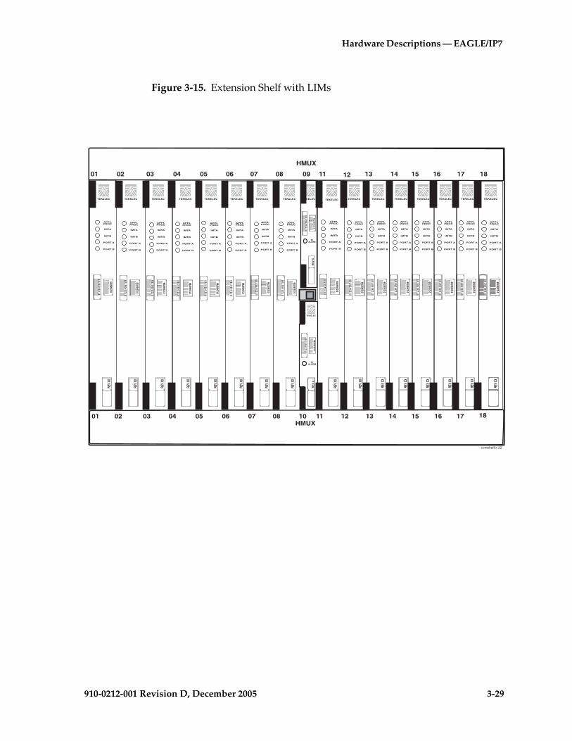
Hardware Descriptions — EAGLE/IP7
910-0212-001 Revision D, December 2005 3-29
Figure 3-15. Extension Shelf with LIMs
�������
� ��!"
� # $ % & ' ( ) * �� �# �$ �% �& �' �( �)
� # $ % & ' ( ) �� �# �$ �% �& �' �( �)
���#�$�%�&�'�(�)�*
�#$
%&'(
)*��+�"
&+�����
���#�$�%�&�'�(�)�*
�#$%&'()*
&+�����
���#�$�%
�&�'�(
�)�*
�#$%&'()*
������,�
���
��-
�,����
�,���-
���#�$�%
�&�'�(
�)�*
�#$%&'()*
������,�
���
��-
�,����
�,���-
���#�$�%
�&�'�(
�)�*
�#$%&'()*
������,�
���
��-
�,����
�,���-
���#�$�%
�&�'�(
�)�*
�#$%&'()*
������,�
���
��-
�,����
�,���-
���#�$�%
�&�'�(
�)�*
�#$%&'()*
������,�
���
��-
�,����
�,���-
���#�$�%
�&�'�(
�)�*
�#$%&'()*
������,�
���
��-
�,����
�,���-
���#�$�%
�&�'�(
�)�*
�#$%&'()*
������,�
���
��-
�,����
�,���-
���#�$�%
�&�'�(
�)�*
�#$%&'()*
������,�
���
��-
�,����
�,���-
���#�$�%
�&�'�(
�)�*
�#$%&'()*
������,�
���
��-
�,����
�,���-
�������1&--
��+�""
��+�""
��+�""
��+�""
��+�""
��+�""
��+�""
��+�""
��+�""
��+�"
�������
�������
���#�$�%
�&�'�(
�)�*
�#$%&'()*
������,�
���
��-
�,����
�,���-
��+�""
���#�$�%
�&�'�(
�)�*
�#$%&'()*
������,�
���
��-
�,����
�,���-
��+�""
�������
���#�$�%
�&�'�(
�)�*
�#$%&'()*
������,�
���
��-
�,����
�,���-
��+�""
�������
���#�$�%
�&�'�(
�)�*
�#$%&'()*
������,�
���
��-
�,����
�,���-
��+�""
�������
���#�$�%
�&�'�(
�)�*
�#$%&'()*
������,�
���
��-
�,����
�,���-
��+�""
�������
���#�$�%
�&�'�(
�)�*
�#$%&'()*
������,�
���
��-
�,����
�,���-
��+�""
�������
���#�$�%
�&�'�(
�)�*
�#$%&'()*
������,�
���
��-
�,����
�,���-
��+�"
"
����������������������������������������������������������������������
��!"
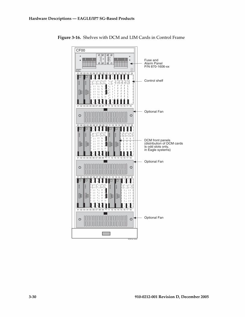
3-30 910-0212-001 Revision D, December 2005
Hardware Descriptions — EAGLE/IP7 SG-Based Products
Figure 3-16. Shelves with DCM and LIM Cards in Control Frame
DCM fan frame
Fuse andAlarm PanelP/N 870-1606-xx
Control shelf
CF00
TEKELEC
01 02 03 04 05 06 07 08 09 10 11 12 13 14 15 16 17 18
01 02 03 04 05 06 07 08 09 10 11 12 13 14 15 16 17 18
01 02 03 04 05 06 07 08 09 10 11 12 13 14 15 16 17 18
01 02 03 04 05 06 07 08 09 10 11 12 13 14 15 16 17 18
01 02 03 04 05 06 07 08 09 10 11 12 13 14 15 16 17 18
01 02 03 04 05 06 07 08 09 10 11 12 13 14 15 16 17 18
DCM front panels(distribution of DCM cardsis odd slots only,in Eagle systems)
Optional Fan
Optional Fan
Optional Fan
Hardware Descriptions — EAGLE/IP7
910-0212-001 Revision D, December 2005 3-31
The extension shelf consists of die-formed top and bottom assemblies with die-formed channel slots to accept the top and bottom edges of the cards. The assemblies are anchored to the side panels which are equipped with integral flanges for attaching the shelf to a 23-inch rack in a 26-inch frame. The shelf backplane consists of an epoxy-glass printed circuit board and associated connectors.
The extension shelf backplane is shown in Figure 3-17 "Extension Shelf Backplane (P/N 850-0356-01)" on page 3-33. Each card is equipped with a power converter that takes the –48VDC input from the backplane and converts it to +5VDC and/or +3VDC.
Extension Shelf Backplanes
This section discusses the technical aspects of the extension shelf backplanes (P/N 850-0356-03/04) and the extension shelf backplanes (P/N 850-0356-01) used in the system.
For extension shelf backplanes (P/N 850-0356-01) refer to Figure 3-17 "Extension Shelf Backplane (P/N 850-0356-01)" on page 3-33
For extension shelf backplanes (P/N 850-0356-03/04) refer to Figure 3-18 "Extension Shelf Backplane (P/N 850-0356-03/04)" on page 3-34
The extension shelf backplane provides connectors for 18 circuit cards. These connectors are four column High Density Interconnect (HDI) male headers with shrouds of varying pin quantities depending on card position. The reverse or component side of the backplane contains DB style connectors for interfacing to the rest of the system. The extension shelf backplane provides shielding on all of the interface connectors to prevent Radio Frequency Interference (RFI).
Power Distribution
CAUTION: This is a redundant system to allow service during normal maintenance. When repairs require a total power disconnect both input supply sources must be disconnected. This will cause service interruption and take down the system.
The extension shelf backplane provides –48VDC power and return to all card positions. The power is divided into parts A and B and brought to the shelf from the Fuse and Alarm Panel (FAP) using two cables (P/N 830-0315-xx). The power connectors on the extension shelf backplane are DB-26 high density connectors with two pins per power connection to handle the current load. The current capacity of the connector pins is 1.5A per pin for a total of 3A per pair. The extension shelf primary power connectors are designated as J4 and J1, and the secondary power connection are on backplane (P/N 850-0356-03/04) are J45 and J46 secondary.
3-32 910-0212-001 Revision D, December 2005
Hardware Descriptions — EAGLE/IP7 SG-Based Products
In the “Installation manual” tables list the shelf location, card type, and fuse location in the fuse and alarm panel for the extension shelf backplane.
NOTE: Cards that are provisioned in redundant pairs must be on separate power buses. This provides backup processing capabilities with the loss of either A or B buses.
Interface Connectors
Behind each slot on the extension shelf backplane are two DB-26 connectors. These provide connection to the outside world in the form of TCP/IP networks, SS7 links, or X.25 networks. The interface connectors are designated as J9 through J40.
System Clock Connectors
Each extension shelf receives and passes along Clock signals A (J5 and J6) and B (J41and J42).
IMT Connectors
The extension shelf backplane provides connections for the two high speed Inter-processor Message Transport (IMT) buses. The connections use twin-axial type connectors at J7, J8, J43, and J44.
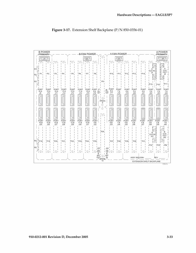
Hardware Descriptions — EAGLE/IP7
910-0212-001 Revision D, December 2005 3-33
Figure 3-17. Extension Shelf Backplane (P/N 850-0356-01)
��8
��9
�� ��,
��. ��� ��- ��7�;�8� �,�9�- �7��
699
�/��>��'>�(��%���5���>�
���A;,.�.7, �BBBBBB �+BBBBBB
697
���/�<
�<
�-
6;68
�
7
-
�' ���6-9
�' �-�6-7
�' �7�6--
�' �9�6-�
�' �,�6-.
�' � �6�<
�' �8�6�;
�' �;�6�8
�' �<�67-
�' �<�6�
�' ��.�67�
�' ��.�6�,
�' ����67.
�' ����6�9
�' ��-�6-<
�' ��-�6�7
�' ��7�6-;
�' ��7�6�-
�' ��9�6-8
�' ��9�6��
�' ��,�6-
�' ��,�6�.
�' �� �6-,
9
,
.7, �.��
67 696-6�
�' �� �6<
�' ���69.
�' �-�67<
�' �7�67;
�' �9�678
�' �,�67
�' � �67,
�' �8�679
�' �;�677
���5�>69�
���5'��69-
���5'��6
���5�>6,
����'��
�����>
���/��.
�79
�7�
�77�7-
�-8 �-; �-< �7.�-,�-9�-7�--�-���< �-.��;
��'=� � ��� A
��'=� � ��� A �%�>�'=� �%�>�'=�

3-34 910-0212-001 Revision D, December 2005
Hardware Descriptions — EAGLE/IP7 SG-Based Products
Figure 3-18. Extension Shelf Backplane (P/N 850-0356-03/04)
NOTE 1: The symbols indicate terminals that conduct -48VDC for the printed circuit boards. (HOT)
NOTE 2: Refer to Figures 3-3 through 3-8 for the DIP switch setting on the individual backplanes. The four DIP switches will all be set the same on the individual backplane. The backplanes on different shelves will have different settings.
J9
J10
J11
J12
J13
J14
J15
J16
J17
J18
J19
J20
J21
J22
J23
J24
J25
J26
J27
J29
J28
J30
J31
J32
J33
J34
J35
J36
J37
J38
J39
J40
J41
J42
J1 J2 J3 J4
J5
J46
J6
J45
J7 J8
J43 J44
850-0356-03
P1 P2 P3 P4 P5 P6 P7 P8 P9 P10 P11 P12 P13 P14
P34P33P32P31P30P29P28P27P26P25P24P23P22P21P20P19P18
P15 P16 P17
123456781112131415161718
Port1A
Port2A
Port3A
Port4A
Port5A
Port6A
Port7A
Port8A
Port11A
Port12A
Port13A
Port14A
Port15A
Port16A
Port10A
Port9A
Port1B
Port2B
Port3B
Port4B
Port5B
Port6B
Port7B
Port8B
Port11B
Port12B
Port13B
Port14B
Port15B
Port16B
Port10B
Port9B
R1
R2
R3
R4
R5
B POWERPRIMARY
B POWERSECONDARY B FAN POWER A FAN POWER
A POWERSECONDARY
A POWERPRIMARY
AIMTOUT
AIMTIN
BIMTIN
BIMTOUT
IPMXB10
ACLKIN
ACLKOUT
BCLKIN
BCLKOUT
IPMX A10
See Note 1 below figure
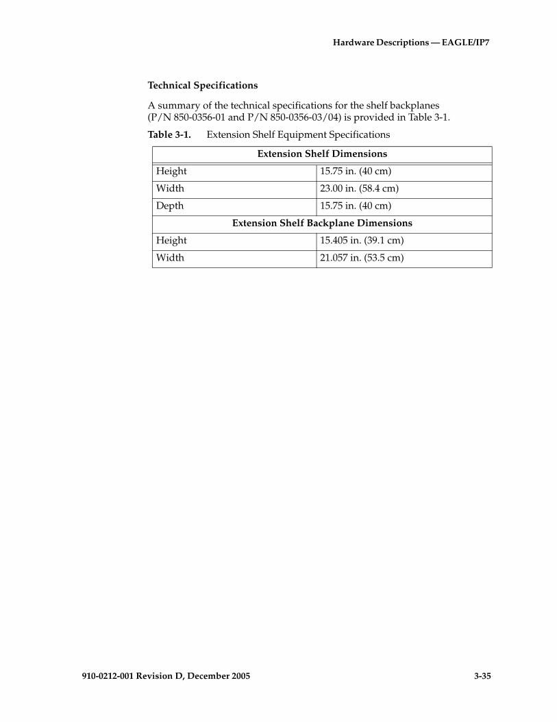
Hardware Descriptions — EAGLE/IP7
910-0212-001 Revision D, December 2005 3-35
Technical Specifications
A summary of the technical specifications for the shelf backplanes (P/N 850-0356-01 and P/N 850-0356-03/04) is provided in Table 3-1.
Table 3-1. Extension Shelf Equipment Specifications
Extension Shelf Dimensions
Height 15.75 in. (40 cm)
Width 23.00 in. (58.4 cm)
Depth 15.75 in. (40 cm)
Extension Shelf Backplane Dimensions
Height 15.405 in. (39.1 cm)
Width 21.057 in. (53.5 cm)
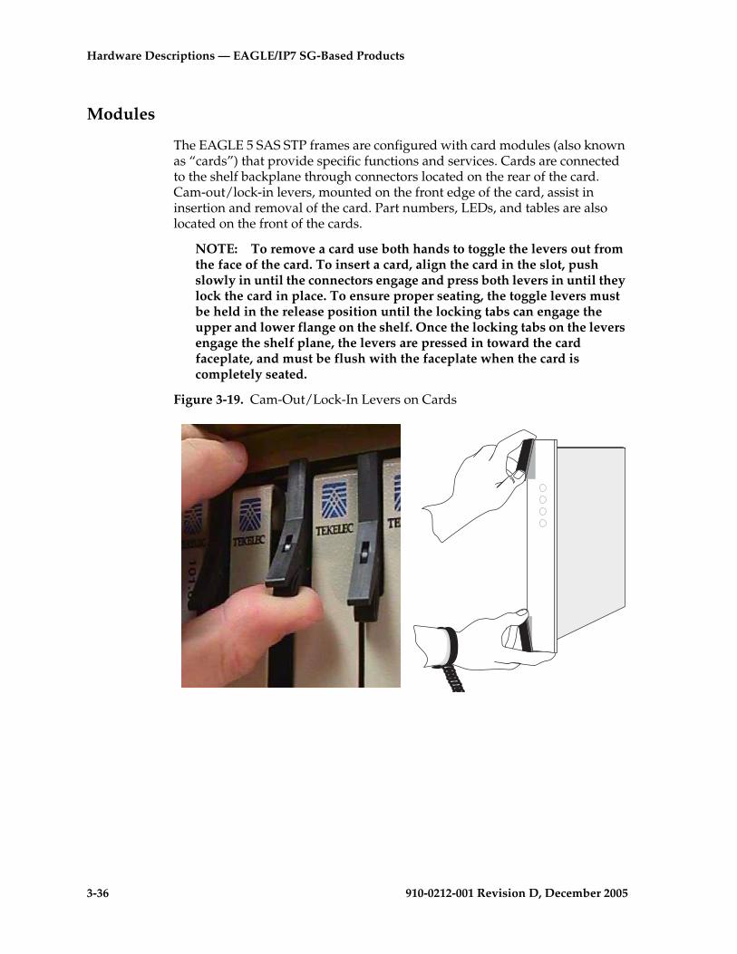
3-36 910-0212-001 Revision D, December 2005
Hardware Descriptions — EAGLE/IP7 SG-Based Products
Modules
The EAGLE 5 SAS STP frames are configured with card modules (also known as “cards”) that provide specific functions and services. Cards are connected to the shelf backplane through connectors located on the rear of the card. Cam-out/lock-in levers, mounted on the front edge of the card, assist in insertion and removal of the card. Part numbers, LEDs, and tables are also located on the front of the cards.
NOTE: To remove a card use both hands to toggle the levers out from the face of the card. To insert a card, align the card in the slot, push slowly in until the connectors engage and press both levers in until they lock the card in place. To ensure proper seating, the toggle levers must be held in the release position until the locking tabs can engage the upper and lower flange on the shelf. Once the locking tabs on the levers engage the shelf plane, the levers are pressed in toward the card faceplate, and must be flush with the faceplate when the card is completely seated.
Figure 3-19. Cam-Out/Lock-In Levers on Cards

Hardware Descriptions — EAGLE/IP7
910-0212-001 Revision D, December 2005 3-37
The modules used in the system are:
• High-Speed IMT Packet Router (HIPR)
NOTE 1: The HIPR card is installed by the factory or by Tekelec Technical Support, not by the customer.
NOTE 2: Shelves must contain either HMUX or HIPR cards. A mixture of HMUX and HIPR cards within one IMT ring is possible, provided HIPR is installed on both IMT A and IMT B on a given shelf. HIPR requires all other shelves be equipped with either all HMUX cards or all HIPR cards (shelves cannot contain a mix of HMUX and HIPR).
• High-Speed Multiplexer Card (HMUX)
NOTE: The HMUX card is installed by the factory or by Tekelec Technical Support, not by the customer.
• Maintenance Disk and Alarm Card (MDAL)
• Terminal Disk Module (TDM)
NOTE: Beginning with EAGLE STP Software Release 31.6 Terminal Disk Module cards must be P/N 870-0774-15 to support Global Timing Interface (TDM-GTI)
• General Purpose Service Module (GPSM-II)
NOTE 1: GPSM-II cards are required for the Integrated Sentinel and Time Slot Counter (TSC) synchronization features.
NOTE 2: In EAGLE Release 30.0 the GPSM-II cards must replace existing MCAP cards. The GPSM-II card is installed by the factory or by Tekelec Technical Support, not by the customer.
• Link Interface Modules (LIM)
• Database Communications Module and Database Service Module (DCM) and Database Service Module (DSM) (EAGLE 5 SAS STP) can only be located in odd numbered slots and requires two slots.
• Application Communications Module (ACM)
• Translation Service Module (TSM)
• Integrated LIM Applique Interface (ILA) or Enhanced Integrated LIM Applique Interface (EILA)
• Multi-Port Link Interface Module (MPL) (EAGLE 5 SAS STP)
• E1/T1 Multi-Channel Interface Module (MIM) (EAGLE 5 SAS STP)
• High-capacity Multi-Channel Interface Module (HCMIM)
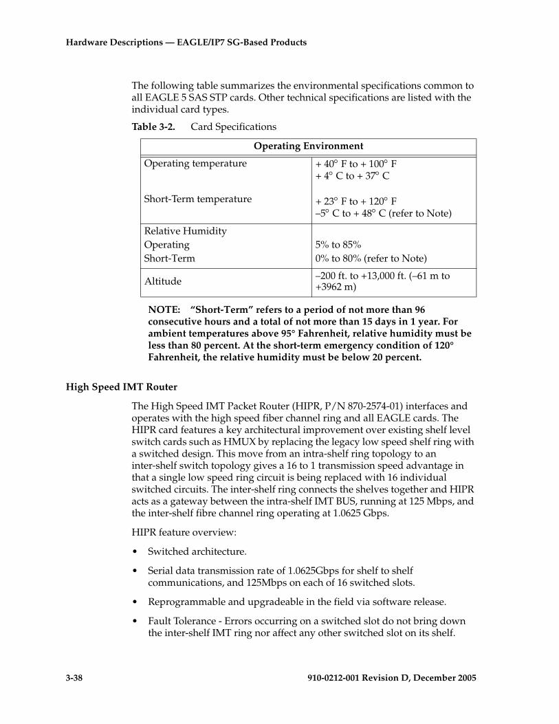
3-38 910-0212-001 Revision D, December 2005
Hardware Descriptions — EAGLE/IP7 SG-Based Products
The following table summarizes the environmental specifications common to all EAGLE 5 SAS STP cards. Other technical specifications are listed with the individual card types.
NOTE: “Short-Term” refers to a period of not more than 96 consecutive hours and a total of not more than 15 days in 1 year. For ambient temperatures above 95° Fahrenheit, relative humidity must be less than 80 percent. At the short-term emergency condition of 120° Fahrenheit, the relative humidity must be below 20 percent.
High Speed IMT Router
The High Speed IMT Packet Router (HIPR, P/N 870-2574-01) interfaces and operates with the high speed fiber channel ring and all EAGLE cards. The HIPR card features a key architectural improvement over existing shelf level switch cards such as HMUX by replacing the legacy low speed shelf ring with a switched design. This move from an intra-shelf ring topology to an inter-shelf switch topology gives a 16 to 1 transmission speed advantage in that a single low speed ring circuit is being replaced with 16 individual switched circuits. The inter-shelf ring connects the shelves together and HIPR acts as a gateway between the intra-shelf IMT BUS, running at 125 Mbps, and the inter-shelf fibre channel ring operating at 1.0625 Gbps.
HIPR feature overview:
• Switched architecture.
• Serial data transmission rate of 1.0625Gbps for shelf to shelf communications, and 125Mbps on each of 16 switched slots.
• Reprogrammable and upgradeable in the field via software release.
• Fault Tolerance - Errors occurring on a switched slot do not bring down the inter-shelf IMT ring nor affect any other switched slot on its shelf.
Table 3-2. Card Specifications
Operating Environment
Operating temperature
Short-Term temperature
+ 40° F to + 100° F+ 4° C to + 37° C
+ 23° F to + 120° F –5° C to + 48° C (refer to Note)
Relative HumidityOperatingShort-Term
5% to 85%0% to 80% (refer to Note)
Altitude –200 ft. to +13,000 ft. (–61 m to +3962 m)
Hardware Descriptions — EAGLE/IP7
910-0212-001 Revision D, December 2005 3-39
• Provides easy upgrade path from HMUX ring architecture.
Switched Architecture
The inter-shelf ring connects the shelves together and HIPR acts as a gateway between the intra-shelf IMT BUS, running at 125 Mbps, and the inter-shelf fibre channel ring operating at 1.0625 Gbps. HIPR retains the high speed 1Gb Fiber Channel ring as a way to ensure interoperability with HMUX equipped shelves. After HIPR recognizes that data from the high speed ring is destined for its shelf address, the data is immediately switched to the correct card within the shelf rather than traversing a 125MB ring.
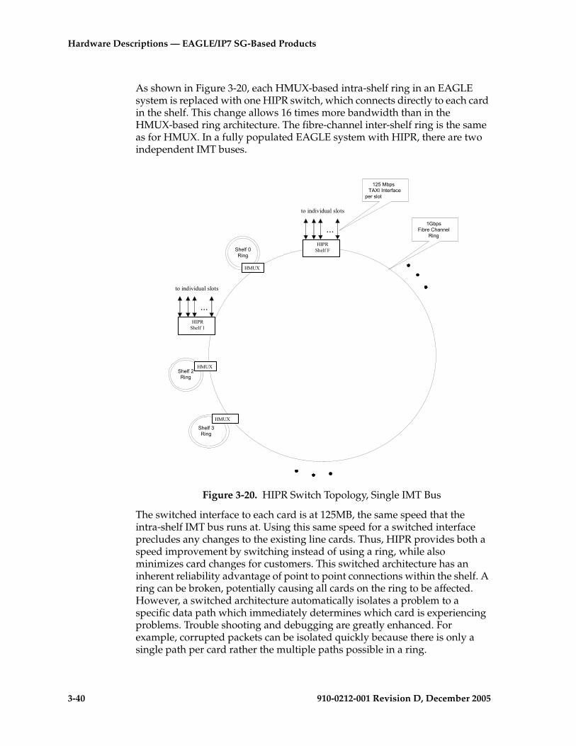
3-40 910-0212-001 Revision D, December 2005
Hardware Descriptions — EAGLE/IP7 SG-Based Products
As shown in Figure 3-20, each HMUX-based intra-shelf ring in an EAGLE system is replaced with one HIPR switch, which connects directly to each card in the shelf. This change allows 16 times more bandwidth than in the HMUX-based ring architecture. The fibre-channel inter-shelf ring is the same as for HMUX. In a fully populated EAGLE system with HIPR, there are two independent IMT buses.
Figure 3-20. HIPR Switch Topology, Single IMT Bus
The switched interface to each card is at 125MB, the same speed that the intra-shelf IMT bus runs at. Using this same speed for a switched interface precludes any changes to the existing line cards. Thus, HIPR provides both a speed improvement by switching instead of using a ring, while also minimizes card changes for customers. This switched architecture has an inherent reliability advantage of point to point connections within the shelf. A ring can be broken, potentially causing all cards on the ring to be affected. However, a switched architecture automatically isolates a problem to a specific data path which immediately determines which card is experiencing problems. Trouble shooting and debugging are greatly enhanced. For example, corrupted packets can be isolated quickly because there is only a single path per card rather the multiple paths possible in a ring.
1Gbps Fibre Channel
Ring HIPR
Shelf F
HIPR Shelf 1
...
to individual slots
...
to individual slots
125 MbpsTAXI Interface
per slot
Shelf 0Ring
HMUX
Shelf 3 Ring
Shelf 2 Ring
HMUX
HMUX
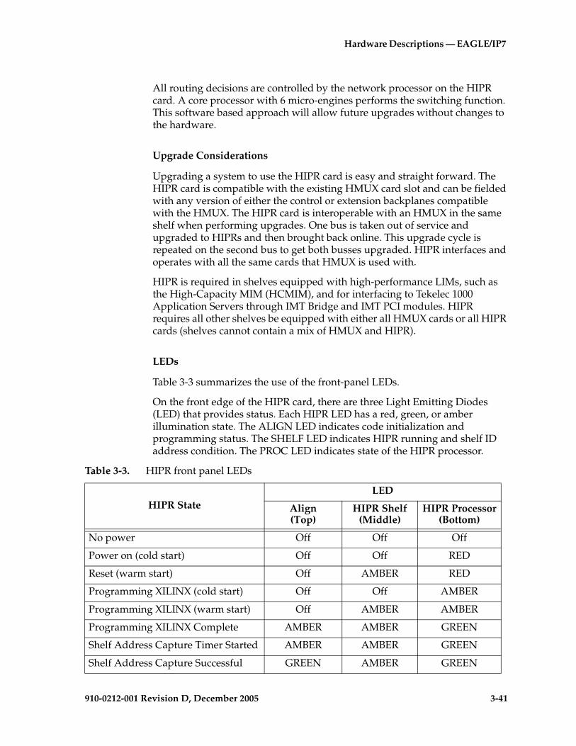
Hardware Descriptions — EAGLE/IP7
910-0212-001 Revision D, December 2005 3-41
All routing decisions are controlled by the network processor on the HIPR card. A core processor with 6 micro-engines performs the switching function. This software based approach will allow future upgrades without changes to the hardware.
Upgrade Considerations
Upgrading a system to use the HIPR card is easy and straight forward. The HIPR card is compatible with the existing HMUX card slot and can be fielded with any version of either the control or extension backplanes compatible with the HMUX. The HIPR card is interoperable with an HMUX in the same shelf when performing upgrades. One bus is taken out of service and upgraded to HIPRs and then brought back online. This upgrade cycle is repeated on the second bus to get both busses upgraded. HIPR interfaces and operates with all the same cards that HMUX is used with.
HIPR is required in shelves equipped with high-performance LIMs, such as the High-Capacity MIM (HCMIM), and for interfacing to Tekelec 1000 Application Servers through IMT Bridge and IMT PCI modules. HIPR requires all other shelves be equipped with either all HMUX cards or all HIPR cards (shelves cannot contain a mix of HMUX and HIPR).
LEDs
Table 3-3 summarizes the use of the front-panel LEDs.
On the front edge of the HIPR card, there are three Light Emitting Diodes (LED) that provides status. Each HIPR LED has a red, green, or amber illumination state. The ALIGN LED indicates code initialization and programming status. The SHELF LED indicates HIPR running and shelf ID address condition. The PROC LED indicates state of the HIPR processor.
Table 3-3. HIPR front panel LEDs
HIPR StateLED
Align(Top)
HIPR Shelf(Middle)
HIPR Processor(Bottom)
No power Off Off Off
Power on (cold start) Off Off RED
Reset (warm start) Off AMBER RED
Programming XILINX (cold start) Off Off AMBER
Programming XILINX (warm start) Off AMBER AMBER
Programming XILINX Complete AMBER AMBER GREEN
Shelf Address Capture Timer Started AMBER AMBER GREEN
Shelf Address Capture Successful GREEN AMBER GREEN

3-42 910-0212-001 Revision D, December 2005
Hardware Descriptions — EAGLE/IP7 SG-Based Products
NOTE 1: The Top and Middle LEDs are not accessible to software until the FPGA has been programmed. So for the same point in the HIPR bootstrap sequence, the state of these two LEDs can be different depending on whether a warm or cold start is in progress.
NOTE 2: State depends on the address received from OAM and written to Assigned Shelf Address Register and compared to the value previously read from the Assigned Shelf Address Register:
RED - Does not matchGREEN -Matches
Technical Specifications
Shelf Address Capture Unsuccessful RED AMBER GREEN
Code Running GREEN Note 2 GREEN
Table 3-3. HIPR front panel LEDs
HIPR StateLED
Align(Top)
HIPR Shelf(Middle)
HIPR Processor(Bottom)
Table 3-4. HIPR Technical Specifications
Power Requirements
Voltage -48VDC
Current 310mA
Power 15W typical, 22W max.
Physical Characteristics
Height 7.7 in. (18.3 cm)
Width 1.8 in. (2 cm)
Depth 12.8 in. (32.5 cm)

Hardware Descriptions — EAGLE/IP7
910-0212-001 Revision D, December 2005 3-43
High-Speed Multiplexer Card
The High-Speed Multiplexer (HMUX) (P/N 870-1965-xx) card, used in EAGLE 5 SAS STP systems only, supports requirements for more than 1024 links. The HMUX card requires the 850-0330-06 control shelf backplane.
NOTE 1: The HMUX card can be used with Control Shelf Backplane (P/N 850-0330-03/04) in the EAGLE 5 SAS STP system with minor modifications and the addition of adapter cable (P/N 830-0857-01).
NOTE 2: HMUX cards are required to support the Integrated EAGLE/Sentinel monitoring feature.
NOTE 3: HMUX or HIPR cards are required for EAGLE Release 30.0 and higher, they replace IPMX cards used with a prior release. They are installed at the factory or by Tekelec Technical Support, not by the customer.
With HMUX cards, the IPMX ring topology is broken into separate ring sections, allowing fault tolerance and higher data throughput rates. Each shelf is a separate secondary IMT ring.
The HMUX Card acts as a gateway between the shelf's IMT ring and the inter-shelf ring. Using the HMUX card transforms the EAGLE 5 SAS STP from a single 125 Mbps ring to a centralized intra-shelf ring running at 1.0625 Gbps, connecting a maximum of sixteen secondary, 125 Mbps shelf rings. Figure 3-21 displays the HMUX ring topology.

3-44 910-0212-001 Revision D, December 2005
Hardware Descriptions — EAGLE/IP7 SG-Based Products
Figure 3-21. HMUX Ring Topology
Most messages from one slot to another on the same shelf remain on that shelf’s ring. This reduces traffic loading on the high-speed inter-shelf ring. The inter-shelf links form a separate ring used only for inter-shelf communications. The topology changes affect both IMT rings: IMTA and IMTB.
HMUX Addressing
In order to communicate with the GPSM-II card, each HMUX now has its own address in the IMT network. The active OAM selectively sends a physical address shelf ID to each pair (A-bus, B-bus) of HMUX cards on a per-shelf basis. The A-bus and B-bus HMUX cards for a given shelf share the same physical address.
Physical Layout
The HMUX (EAGLE 5 SAS STP) is designed to plug into the existing shelf backplane, using the same slots the IPMX cards have occupied. Figure 3-22 shows a side view of the HMUX card. Table 3-5 summarizes the technical specifications of the HMUX card.
���������
������ ��
���������
���������
���������
���������
���������
���������
��������������
���������
��������������
���������
���������
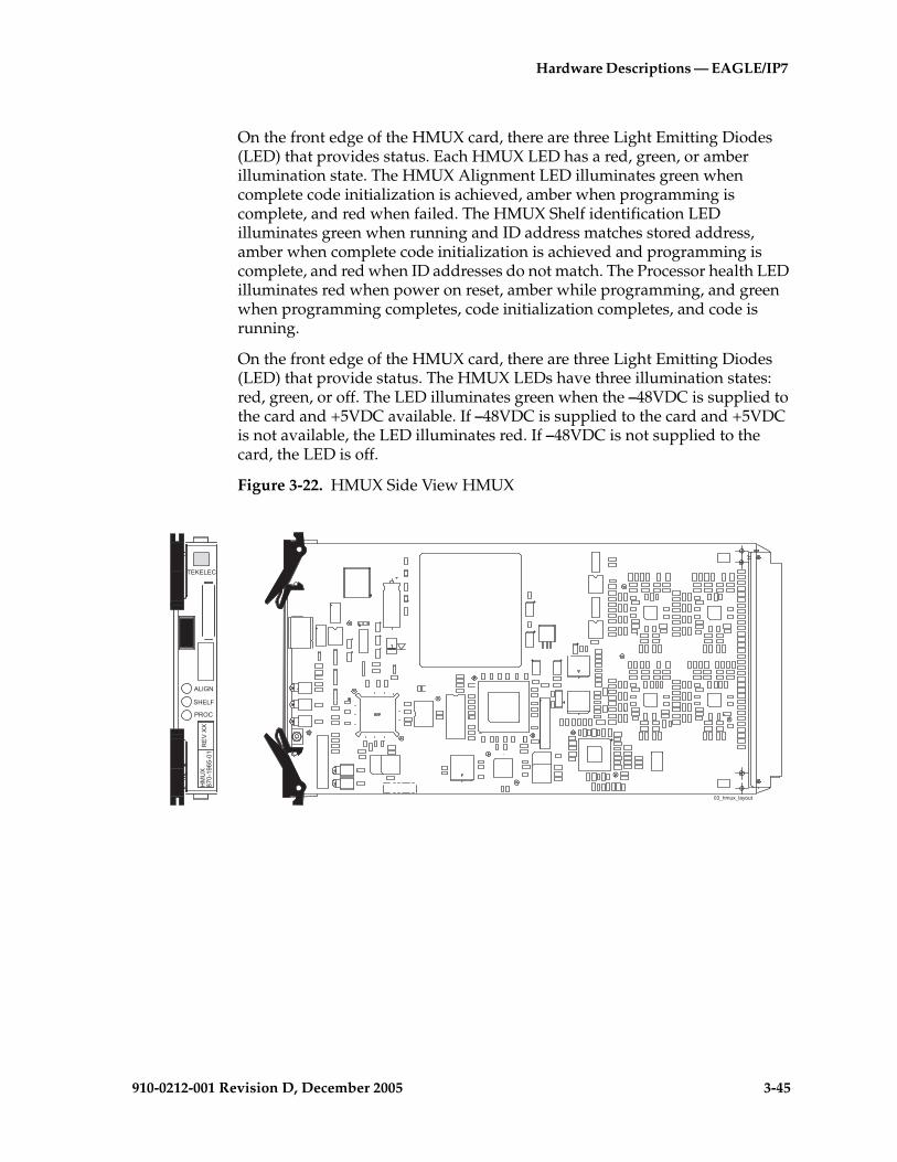
Hardware Descriptions — EAGLE/IP7
910-0212-001 Revision D, December 2005 3-45
On the front edge of the HMUX card, there are three Light Emitting Diodes (LED) that provides status. Each HMUX LED has a red, green, or amber illumination state. The HMUX Alignment LED illuminates green when complete code initialization is achieved, amber when programming is complete, and red when failed. The HMUX Shelf identification LED illuminates green when running and ID address matches stored address, amber when complete code initialization is achieved and programming is complete, and red when ID addresses do not match. The Processor health LED illuminates red when power on reset, amber while programming, and green when programming completes, code initialization completes, and code is running.
On the front edge of the HMUX card, there are three Light Emitting Diodes (LED) that provide status. The HMUX LEDs have three illumination states: red, green, or off. The LED illuminates green when the –48VDC is supplied to the card and +5VDC available. If –48VDC is supplied to the card and +5VDC is not available, the LED illuminates red. If –48VDC is not supplied to the card, the LED is off.
Figure 3-22. HMUX Side View HMUX
��5����
���:>
�(��%
� '�
�+//
(��/
;8.��< ,�.�
.7B���&B�)���

3-46 910-0212-001 Revision D, December 2005
Hardware Descriptions — EAGLE/IP7 SG-Based Products
Maintenance Disk and Alarm Card
The Maintenance Disk and Alarm (MDAL) card (P/N 870-0773-xx) is a multi-layered circuit card that provides the system with removable cartridge data storage, alarm processing from the currently active MASP, and an audible alarm. A drawing of the MDAL is shown in Figure 3-23 "Maintenance Disk and Alarm Card" on page 3-48.
NOTE: Fan trays are recommended for control shelves on systems implementing large LNP database applications (large means above 1 Gbyte) to prevent overheating of the MDAL card during long backup or restore procedures.
The LEDs on the front faceplate indicate critical, major, and minor alarms and card activity.
Alarm Circuits
The MDAL processes alarms generated from the active MASP and passed to the MDAL on the alarm data bus. The alarm signals are sent as follows.
Critical, major, and minor alarms:
• The fuse and alarm panel of each control or extension rack
• End panel with alarm lamps
• Local Maintenance Center (LMC)
• Remote Maintenance Center (RMC)
• Maintenance Disk and Alarm (MDAL) card
Table 3-5. HMUX Technical Specifications
Power Requirements
Voltage -48VDC
Current 3.2A-4.5A
Power 16W typical, 22W max.
Physical Characteristics
Height 7.7 in. (18.3 cm)
Width 1.8 in. (2 cm)
Depth 12.8 in. (32.5 cm)

Hardware Descriptions — EAGLE/IP7
910-0212-001 Revision D, December 2005 3-47
Audible alarm is sent to:
• Local Maintenance Center (LMC)
• Remote Maintenance Center (RMC)
• Maintenance Disk and Alarm (MDAL) card
Removable Media Cartridge
The removable media cartridge is a magneto-optical disk used in the MDAL, (P/N 870-0773-04/-05) to install and back up customer data. For larger capacity equipment compliance and to install and back up customer data, a 5.2 Gbyte cartridge magneto-optical disk may be used in MDAL card (P/N 870-0773-06).
Power Converter Unit
MDAL power is provided by a DC to DC converter that converts the –48VDC supplied to the system to the +5VDC needed to power the MDAL components.

3-48 910-0212-001 Revision D, December 2005
Hardware Descriptions — EAGLE/IP7 SG-Based Products
Figure 3-23. Maintenance Disk and Alarm Card
.7B���B"������)���
� ��������6'
��>'
������
������
�+/
�#��
;8.�.887�
�!��������"��
�������"��
��������"��
��������
��5����
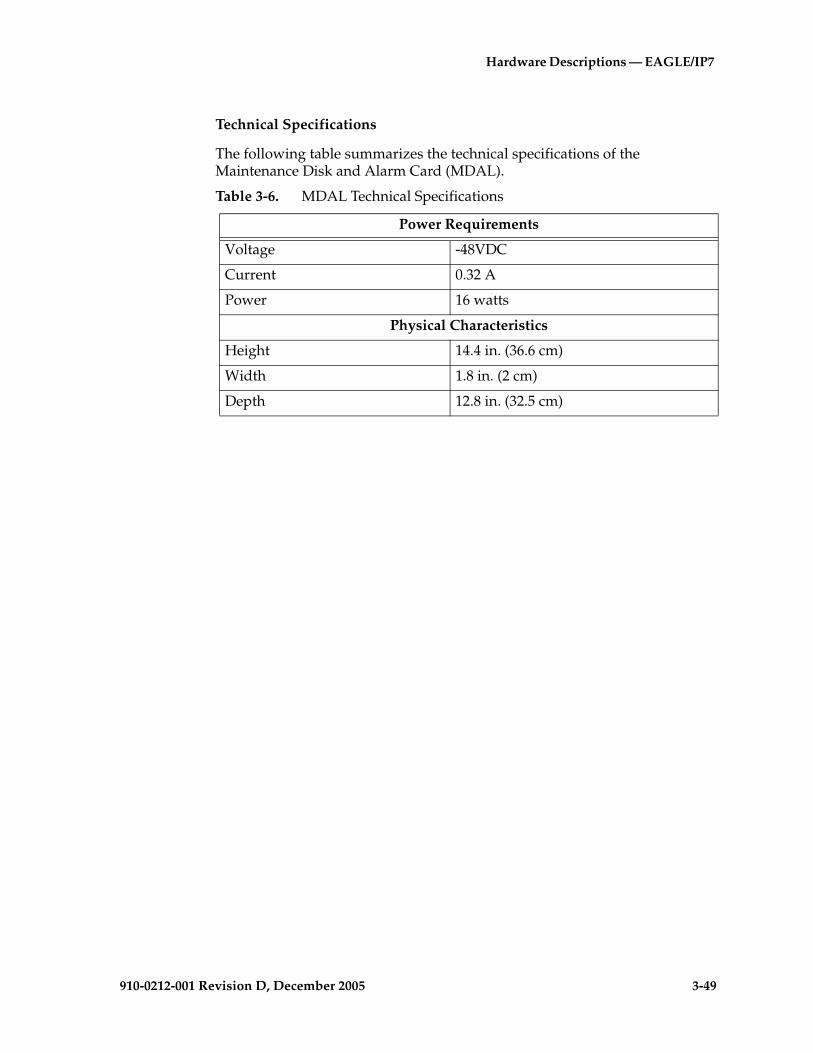
Hardware Descriptions — EAGLE/IP7
910-0212-001 Revision D, December 2005 3-49
Technical Specifications
The following table summarizes the technical specifications of the Maintenance Disk and Alarm Card (MDAL).
Table 3-6. MDAL Technical Specifications
Power Requirements
Voltage -48VDC
Current 0.32 A
Power 16 watts
Physical Characteristics
Height 14.4 in. (36.6 cm)
Width 1.8 in. (2 cm)
Depth 12.8 in. (32.5 cm)

3-50 910-0212-001 Revision D, December 2005
Hardware Descriptions — EAGLE/IP7 SG-Based Products
Terminal Disk Module
The Terminal Disk Module (TDM) (P/N 870-0774-xx) provides the following functions for the EAGLE system:
• “Building Integrated Timing System Interfaces”
• “Fuse Alarm Interface”
• “External/Customer Alarm Interface”
• “Maintenance Disk and Alarm Interface”
• “Small Computer System Interface”
• “Terminal Processor”
• “Extended Bus Interface”
• “Global Timing Interface”
• “Hard Drive”
• “Power Converter Unit”
NOTE: The Time Slot Counter (TSC) synchronization capability in the TDM, which is required for the Integrated Sentinel feature, is implemented in TDM board (P/N 870-0774-10 and later). The Integrated Sentinel feature requires EAGLE release 28.0 and Sentinel release 8.0 or later versions.
NOTE: Beginning with EAGLE STP Software release 30.0 all Terminal Disk Module cards must be P/N 870-0774-11 or later.
NOTE: Beginning with EAGLE STP Software Release 31.6 Terminal Disk Module cards must be P/N 870-0774-15 to support Global Timing Interface (TDM-GTI).
NOTE: The EAGLE internal composite clock sourced from the high speed clock feature of the TDM-GTI is not available to systems with DS0 cards. Customers with DS0 links can use BITS clocks as the TSC synchronization clock source.
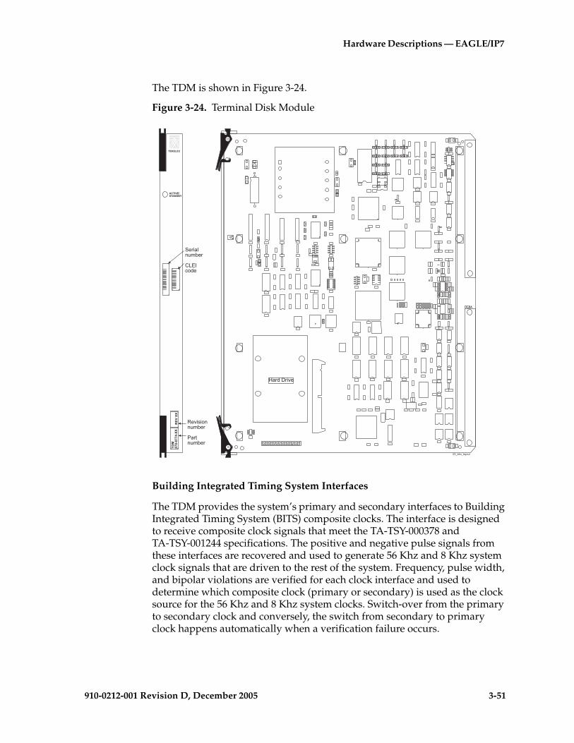
Hardware Descriptions — EAGLE/IP7
910-0212-001 Revision D, December 2005 3-51
The TDM is shown in Figure 3-24.
Figure 3-24. Terminal Disk Module
Building Integrated Timing System Interfaces
The TDM provides the system’s primary and secondary interfaces to Building Integrated Timing System (BITS) composite clocks. The interface is designed to receive composite clock signals that meet the TA-TSY-000378 and TA-TSY-001244 specifications. The positive and negative pulse signals from these interfaces are recovered and used to generate 56 Khz and 8 Khz system clock signals that are driven to the rest of the system. Frequency, pulse width, and bipolar violations are verified for each clock interface and used to determine which composite clock (primary or secondary) is used as the clock source for the 56 Khz and 8 Khz system clocks. Switch-over from the primary to secondary clock and conversely, the switch from secondary to primary clock happens automatically when a verification failure occurs.
.7B���B�)���
�����.���/� 0
������
��������"��
��������
�����
����
����
������
�
�!��������"��
�������"��
(���#��!�

3-52 910-0212-001 Revision D, December 2005
Hardware Descriptions — EAGLE/IP7 SG-Based Products
Fuse Alarm Interface
The TDM receives fuse alarm signals from the fuse and alarm panels of each frame. Each fuse alarm has two connections, RxFA- and RxFA+. No alarm is indicated with an open circuit between the connections, and an alarm is indicated by a short circuit between the two connections.
External/Customer Alarm Interface
The TDM provides interfacing for up to 10 external/customer alarms or, 26 external/customer alarms if Cus. Alarm 2, J66, is supported. Each alarm has an individual connection along with common contacts through the power ground provided by the control shelf backplane.
Maintenance Disk and Alarm Interface
The interface to the Maintenance Disk and Alarm Interface (MDAL) card consists of an 8-bit bidirectional data bus, five alarm register enable signals, and an alarm clock. The clock Logic Cell Array (LCA) is used to implement the logic for the MDAL card interface.
Small Computer System Interface
The TDM contains two separate Small Computer System Interface (SCSI) buses. Each bus uses an NCR 53C720 SCSI I/O processor as the SCSI bus controller. SCSI Processor A controls the SCSI bus to the fixed disk, which is installed on the TDM. SCSI Processor B controls the SCSI bus connected to the removable disk, which is part of the MDAL card. Both the MASP-A TDM and the MASP-B TDM use this SCSI bus to communicate with the removable drive. The removable drive SCSI bus is always terminated on the MDAL card.
Terminal Processor
The TDM terminal processor interfaces 16 RS-232 terminals to the TDMs associated General Purpose Service Module II (GPSM-II) cards. The core of the TDM terminal processor is an 80C386XL microprocessor. Two 2698 Octal Universal Asynchronous Receiver Transmitter (OCTART) devices are used to interface the 80C386XL microprocessor to the 16 serial terminal ports. The 80C386XL microprocessor receives data from the GPSM-II and transmits it to the terminals.

Hardware Descriptions — EAGLE/IP7
910-0212-001 Revision D, December 2005 3-53
Extended Bus Interface
The Extended Bus Interface (EBI) links the TDM to its associated General Purpose Service Module II (GPSM-II), in the same Maintenance and Administration Subsystem Processor (MASP), through the EBI host processor bus. The purpose of the TDM is to provide additional logic, memory, and interfacing for the GPSM-II card. The EBI bus interfaces with every function on the TDM, either directly or indirectly.
Global Timing Interface
The EAGLE internal composite clock sourced from the high speed clock feature of the TDM-GTI is not available to systems with DS0 cards. Customers with DS0 links can use the BITS clocks as the TSC clock source.
The TDM Global Timing Interface (TDM-GTI) (P/N 870-0774-15) EAGLE release 31.6 is compatible to EAGLE release 29.0 and later. TDM-GTI has enhancements (utilized in release 31.6 and later) that generate high speed master clocks from a recovered E1/T1 clock and the optional ability to reload the clock’s Logic Cell Array (LCA) bitfile when the mated GPSM-II is initialized.
Requirements:
1. The type of external clock introduced into the EAGLE System must be compatible with the EAGLE System.
2. The location where the external clock is introduced must be recognized by the EAGLE System.
3. The external clock must be provisioned to communicate with the EAGLE.
The TDM-GTI has an additional clock feature related to TSC synchronization. The TDM-GTI allows the TSC synchronization feature to be sourced from the high speed clock and to be the master high speed clocking with the following interfaces. The cards use this clock signal to generate a time stamp that is synchronized across the system. This time stamp is required when using the Sentinel monitoring system.
1. New Interfaces:
a. T1 framed clocking per American Standards National Institute(ANSI)T1.101, Synchronization Interface Standards-1999 .
b. T1 unframed clocking per section 5 of ITU, Standard G.703. The hardware supports this clock and the FE005011 will be updated to include this clock.
c. E1 framed clocking per Section 9 of (translation from French, ITU) Consultative Committee on International Telegraphy and Telephone, standard G.703.
3-54 910-0212-001 Revision D, December 2005
Hardware Descriptions — EAGLE/IP7 SG-Based Products
d. E1 unframed clocking per Section 13 of ITU, Standard G.703.
2. Existing Interfaces:
a. 64/8 Kilo Hertz (KHz) Return To Zero (RTZ) Composite Clock Interface
b. E1 (2048 KHz) RS-422 Clock Interface
c. T1 (1544 KHz) RS-422 Clock Interface
Hard Drive
The hard drive on the TDM is used to store primary and backup system databases, measurements, and Generic Program Loads (GPLs). The hard drive capacities are:
• 9GB (TDM 870-0774-10)
• 18GB (TDM 870-0774-11)
• 36GB (TDM-GTI 870-0774-15)
Power Converter Unit
The TDM is powered by an on-board DC to DC converter. The converter accepts –48VDC and supplies +5VDC and +12VDC to the TDM.
Table 3-7. TDM Technical Specifications
Power Requirements
Voltage -48VDC
Current 0.46 A
Power 22 Watts
Dimensions
Height 15.0 in. (38.1 cm)
Width 1.8 in. (2 cm)
Depth 12.8 in. (32.5 cm)

Hardware Descriptions — EAGLE/IP7
910-0212-001 Revision D, December 2005 3-55
Time Slot Counter Synchronization
The Time Slot Counter (TSC) Synchronization feature is an advanced function enabled in all LIMs with EAGLE release 28.0 and later. The TSC Synchronization feature does not require any physical hardware changes to any of the boards in the EAGLE system. TSC Synchronization is an optional feature for the EAGLE 5 SAS STP that will allow all cards in the system, which contain a Time Slot Counter, to synchronize with one another. The ability to have synchronized timing between cards is used in applications such as system wide message time stamping.
The TSC Synchronization feature requires the MCAP cards in slots 1113 and 1115 of the control shelf be replaced with GPSM-II cards. The TSC sync feature also requires the associated TDM cards be updated to (P/N 870-0774-10 or later). A typical EAGLE system will have two TDMs installed to distribute both the A and B system clocks. The TSC Sync feature has to be enabled on both TDMs. The EAGLE system must use an external BITS clock so that the system A and B clocks remain synchronous to each other. If either of the TDMs provides its internal clock to the system instead of the BITS clock, the A and B clocks may drift apart and introduce skew into the system.
After the TSC Sync feature is enabled there may be skew between the A clock and B clock TSC Reset Events. This skew must be detected and eliminated so that cards can switch between the two clocks and stay synchronized to the rest of the system. All cards with a TSC have a Skew Interrupt and the Skew Count register, but the GPSM-II card is unique in that it can communicate with the TDM and adjust the skew.
TSC Sync affects the TDM (P/N 870-0774-10 or later) and all EAGLE 5 SAS STP cards that contain a Time Slot Counter. This includes:
• E486-based and E586-based cards (ILA, EILA, ILE1, EILA-T, MCAP-256, TSM, E586-T)
• HCAP or HCAP-T
• DCM, DCMX, EDCM and EDCM-A, and GPSM-II (single-slot EDCM)
• MPL, MPL-T, and E1/T1 MIM
Beginning with EAGLE STP Software Release 31.6 Terminal Disk Module cards must be P/N 870-0774-15 to support Global Timing Interface (TDM-GTI)
3-56 910-0212-001 Revision D, December 2005
Hardware Descriptions — EAGLE/IP7 SG-Based Products
Link Interface Modules
After the frame has been shipped or moved, prior to applying power, remove all cards. Reset all cards carefully to avoid possible faulty connections.All cards are hot swappable
The Link Interface Module (LIM) provides access to remote SS7, X.25, IP and other network elements, such as a Signaling Control Point (SCP). The LIMs consist of a main assembly and possibly, an interface applique board. These appliques provide level one and some level two functionality on SS7 signaling links. The types of LIMs presently available are:
• LIM-DS0A is a specialized LIM that provides two Digital Signal Level 0 Applique DS0A interfaces at 56 kbps, (P/N 870-1009-xx). This module uses a DS0A applique. (This board is no longer shipped but it does exist, in use, in the field, replaced by the LIM-AINF which has been replaced by the Integrated LIM Applique, ILA, and the EILA)
• LIM-OCU is a specialized LIM that provides two Office Channel Unit (OCU) interfaces at 56 kbps (P/N 870-1010-xx). This module uses an OCU applique.(This board is no longer shipped but it does exist, in use, in the field, replaced by the LIM-AINF which has been replaced by the ILA, and the EILA))
• LIM-V.35 is a specialized LIM that provides one V.35 interface at 56 and 64 kbps for SS7 and 4.8, 9.6, 19.2, 56, and 64 kbps for X.25, (P/N 870-1012-xx). This module uses a V.35 applique.(This board is no longer shipped but it does exist, in use, in the field, replaced by the LIM-AINF which has been replaced by the ILA, and the EILA)
• LIM, LIM-AINF provides DS0A, OCU, V.35 (software selectable), (P/N 870-1014-xx). This module uses an AINF applique. Some versions of this module are labeled LIM-AINF instead of LIM.(This board is no longer shipped but it does exist, in use, in the field, replaced by the ILA, and the EILA)
• LIM-ILA, Integrated LIM Applique, (P/N 870-1484-xx) is an integrated LIM-AINF equal to the same functionality of the LIM-AINF. The

Hardware Descriptions — EAGLE/IP7
910-0212-001 Revision D, December 2005 3-57
difference is the ILA is a single Printed Circuit Board (PCB) without a printed circuit board applique.
• EILA, Enhanced Integrated LIM Applique (P/N 870-2049-xx), is an enhanced integrated LIM-AINF equal to the same functionality of the LIM-AINF. The difference is the larger, 586 processor, of the EILA. In EAGLE release 28.0 an enhanced version of the EILA board (EILA-T) is available.
• The Multi-Port LIM (MPL) (P/N 870-2061-xx), used in EAGLE 5 SAS STP systems only, provides eight DS0 ports transporting SS7 traffic in a single EAGLE 5 SAS STP card slot. Ports A and B are backward compatible with the existing two-port LIM card. Additional ports A1, A2, A3, B1, B2, B3 are DS0 interfaces only. In EAGLE release 28.0 an enhanced version of the MPL board (MPL-T) is available.
The MPL card improves the functionality of SS7 routing within the EAGLE by increasing the number of SS7 links the EAGLE can handle for each LIM card. This allows the EAGLE to interact in larger SS7 networks as well as decreasing the size of an EAGLE (for example, previously 250 cards would be required to support 500 links, now only 63 cards are required).
NOTE: Link Fault Sectionalization (LFS) logic on the MPL provides diagnostic capabilities though network interfaces on ports A and B. LFS tests are extended in EAGLE 5 SAS STP release 27.2 and later to sequentially exercise all eight ports.
NOTE: The MPL card is not used in the IP7 SG system.
• The LIM-E1 card, (P/N 870-1379-xx), and the E1 Interface Kit, (P/N 890-1037-01) with backplane module (P/N 850-0459-01) provides a connection point from the system backplane to an external E1 interface. Two E1 backplane modules are located at the rear of the extension shelf, the upper E1 backplane module and the lower E1 backplane module. The upper and lower backplane modules are identical.
• The E1/T1 Multi-Channel Interface Module (MIM) (P/N 870-2198-02 and P/N 870-2198-01), provides a dual-port (A and B), framed, channelized connection to a customer’s network. The interface to each port is mapped to the DS0 time-slots in the fractional E1 or T1 data streams. Each E1/T1 MIM supports a maximum of eight High-Level Data Link Control (HDLC) channels that can be provisioned as using either E1 or T1 protocols and assigned to any unused time-slot.
NOTE 1: Some earlier releases of the EAGLE software do not support P/N 870-2198-02. See Table A-4 on page A-20.
NOTE 2: E1/T1 MIM cards do not support internal clocking. E1/T1 MIM cards must be provided with either a composite BITS clock or the High-Speed Master Timing clocks to function properly.

3-58 910-0212-001 Revision D, December 2005
Hardware Descriptions — EAGLE/IP7 SG-Based Products
An extension port is provided to connect other boards in the EAGLE shelf to the E1/T1 data stream such that all channels can be mapped (E1 = 32 channels, T1 = 24 channels). This would require four E1/T1 MIMs to map an entire E1 link or three E1/T1 MIMs to map a T1 link. The two ports (1 and 2) can also be put into an ADD/DROP configuration. The E1/T1 MIM would use a fractional part of the data channel connected to port 1 and forward the remaining channel data through port 2.
The E1/T1 MIM card requires a new cable T1 MIM LIM (P/N 830-0894-xx) for T1 interface connections. If replacing existing MPL cards with E1/T1 MIM cards the existing T1 interface cables (P/N 830-0772-xx) must be connected to T1 LIM to MPL adapter cables (P/N 830-0895-xx) or replaced with the new cable (P/N 830-0894-xx).
The existing E1 interface cables (P/N 830-0622-xx) can continue to be used with the new E1/T1 MIM card for E1 applications.
The E1/T1 MIM will implement the ANSI T1 standard for 1.544 MHz data transmission and the European (ITU) E1 standard for 2.048 MHz data transmission.
NOTE: Each E1/T1 MIM port will be capable of operation for E1 or T1 line rates but the interfaces will never be mixed on a single circuit card (for example, one port operating at E1 rates and the other port at T1 rates). The E1/T1 MIM does not support clear-channel (no channels) operation.
• LIM-ATM is a specialized LIM that provides one Asynchronous Transfer Mode over T1 Interface at 1.544 Mbps, (P/N 870-1293-xx). This module uses an Asynchronous Transfer Mode Applique (AATM) installed on a High Capacity Application Processor (HCAP or HCAP-T) main assembly.
• E1-ATM LIM provides one Asynchronous Transfer Mode over E1 Interface at 2.048 Mbps, (P/N 870-2455-01). This module uses an E1 Asynchronous Transfer Mode Applique (E1-ATM) installed on a High Capacity Application Processor (HCAP or HCAP-T) main assembly.
NOTE: The LIM-ATM and E1-ATM LIM appliques are not mounted on the 486 based main assembly. See the section “High-Capacity Application Processor-Based LIMs” on page 3-69 for more information.

Hardware Descriptions — EAGLE/IP7
910-0212-001 Revision D, December 2005 3-59
Maximum Numbers of Links
A maximum of 1500 links can be configured in the EAGLE 5 SAS STP depending on the hardware, software release level, and features that are installed. A mixture of high-speed and low-speed signaling links is supported.
NOTE: If the addition of either a low-speed signaling link or a high-speed signaling link exceeds the total number of low-speed and high-speed signaling links allowed in the system, the ent-slk command is rejected. The addition of a high-speed signaling link decreases the number of low-speed signaling links that can be supported by the system.
Table 3-8, “Hardware Requirements-Maximum Number of Links,” on page 3-60 describes the required hardware for the maximum number of links with different configurations.
NOTE: This table lists EAGLE 5 SAS STP base hardware requirements only. For complete provisioning rules and requirements, including tables listing all link types see the Database Administration - SS7 Manual.
LIM Main Assembly
NOTE: Beginning with EAGLE STP Software release 30.0 all IPMX cards must be replaced by High-Speed Multiplexer (HMUX) cards (P/N 870-1965-01), all MCAP cards must be replaced by GPSM-II cards (P/N 870-2360-01), and Terminal Disk Module cards must be (P/N 870-0774-10) and later. Beginning with EAGLE STP software release 33.0, IPMX cards must be replaced by either HMUX cards or High-Speed IMT Router Cards (P/N 870-2574-01). HMUX, HIPR, and GPSM-II cards are installed at the factory or by Tekelec Technical Support and are not installed by customers.

3-60 910-0212-001 Revision D, December 2005
Hardware Descriptions — EAGLE/IP7 SG-Based Products
Cam-out/lock-in levers, mounted on the front edge of LIM cards, (the exception being E1) assist in the insertion and the removal of the card from the shelf.
Table 3-8. Hardware Requirements-Maximum Number of Links
Number of Links Required Hardware
Up to 500 Links
NOTE: A Maximum of 42 High-speed LIM cards (of which up to 41 can be IPLIMx cards) can be installed
HMUX cards on the IMT buses2-port LIM cards or multi-port LIM cards (MPLs)Installed according to the provisioning rules for a system with up to 500 links in the Database Administration - SS7 Manual.
From 501-700 Links
NOTE: A Maximum 100 High-speed LIM cards (of which up to 41 can be IPLIMx cards) can be installed
HMUX cards on the IMT busesGPSM-II cards installed in card locations 1113 and 1115TDM cards in locations 1114 and 1116
NOTE: There are only enough slots to support 500 links using just 2-port LIMs.
Enough multi-port LIMs (MPLs), P/N 870-2061-XX, to bring the total number of signaling links above 500, up to 700. Installed according to the provisioning rules for a system with 700 links in the Database Administration - SS7 Manual.
From 701--1500 Links
NOTE: A Maximum 115 High-speed LIM cards (of which up to 100 can be IPLIMx cards) can be installed
• HMUX cards on the IMT buses• GPSM-II, P/N 850-0622-XX cards, installed in card
locations 1113 and 1115, to run the active OAM• TDM cards installed in card locations 1114 and 1116
NOTE: There are only enough slots to support 500 links using just 2-port LIMs.
Enough Multi-Port LIMs (MPLs), P/N 870-2061-XX, and/or E1/T1 MIMs, P/N 870-2198-XX, to bring the total number of signaling links to 1500.Installed according to the provisioning rules for a system with 1500 links in the Database Administration - SS7 Manual.

Hardware Descriptions — EAGLE/IP7
910-0212-001 Revision D, December 2005 3-61
The main assembly portion of the LIM contains the following:
• An 80486 applications processor
• An 80386/80486 communications processor that provides a data transmit/receive interface
• An Inter-processor Message Transport (IMT) interface that provides two 125 Mbps communications links that provide communications between modules
• –48VDC/+5VDC and –48VDC/+3VDC DC to DC power converter units
Figure 3-25 shows the LIM Main Assembly card.

3-62 910-0212-001 Revision D, December 2005
Hardware Descriptions — EAGLE/IP7 SG-Based Products
Figure 3-25. Link Interface Module (LIM) Main Assembly
Applications Processor
The Application Processor (AP) section of the LIM interfaces and controls the operation of the interface applique. The AP’s operations are controlled by an 80486 processor and peripherals.
870-1289-XX TSM

Hardware Descriptions — EAGLE/IP7
910-0212-001 Revision D, December 2005 3-63
Communications Processor
The Communications Processor (CP) is made up of an 80386/80486 microprocessors and peripherals. The CP section of the LIM controls the flow of transmit/receive data to and from the Inter-processor Message Transport (IMT) buses.
In the receive direction, the CP writes a receive initialization command to the IMT bus. The data packet is checked for the destination. If its destination is this LIM, the format is checked and a Cyclic Redundancy Check (CRC) is performed. The packet is then transferred to the CP memory by Direct Memory Access (DMA).
In the transmit direction, the CP forwards a packet along with 2 CRC bytes, calculated by the IMT circuitry, to the HMUX or HIPR cards (EAGLE 5 SAS STP) for transmission.
The CP also controls the selection of the IMT buses, A or B. In the other direction, the CP forwards data received from the IMT buses through the AP to the interface port (DB15) connector on the shelf backplane.
The CP is interrupt driven. Eight levels of the interrupts initiated by the IMT, the AP, and the MAS, are administered by a Programmable Interrupt Controller (PIC).
Inter-processor Message Transport
Each LIM unit has two Inter-processor Message Transport (IMT) interface circuits, IMT A and IMT B. The redundant IMT buses are used to transport:
• Generic Program Loads (GPLs) to various circuit cards
• All SS7 and traffic between circuit cards
• Maintenance traffic within the system
In the receive direction, a data packet is checked to see if it is destined for this particular LIM. If it is, the packet is checked for format and a cyclic redundancy check is performed. The packet is then transferred to the CP memory by Direct Memory Access (DMA). If the packet is not destined for this LIM, it is sent back onto the IMT bus towards the next module.
In the transmit direction, the Cyclic Redundancy Check (CRC) is calculated for a packet and the packet is transmitted through the HIPR cards (EAGLE 5 SAS STP) to the IMT bus.
Power Converter Unit
LIM power is provided by two DC to DC converters that convert the –48VDC supplied to the system to +5VDC and +3VDC needed to power the LIM components.

3-64 910-0212-001 Revision D, December 2005
Hardware Descriptions — EAGLE/IP7 SG-Based Products
Test and Maintenance Features
Colored LEDs are mounted on the front edge of the printed circuit board as LIM status and alarm indicators.
Digital Signal Level-0 Applique
The DS0A applique is mounted on the LIM main assembly. A 128-pin and a 60-pin connector engage two male connectors on the LIM main assembly. The DS0A’s applique primary function is to provide the LIM with access to the DS0 link. Figure 3-26 "Digital Signal Level-0 Applique" on page 3-65 shows the DS0A applique.
The DS0A applique provides two 64 KHz DS0 ports. The microprocessor on the LIM commands the ISCC to operate in the SDLC mode to transmit and receive an SS7 data stream. The ISCC retrieves and stores SS7 messages in the dual port memory locations on the LIM through Direct Memory Access (DMA).
The signal clocking for the DS0A card is provided by system clocks derived from the Building Integrated Timing System (BITS) composite clock signal.
Each DS0 interface has one balanced pair for each direction of transmission and reception. The transmitted data from the ISCC is converted to the bipolar data format before being transmitted to a DS0 link. The received DS0 signal is converted to the NRZ data format before arriving at the ISCC.
The transmitted data is read from the LIM's memory into the Integrated Serial Communications Controller (ISCC) by way of DMA, and a proper data frame, with self-calculated CRC bits, is then transmitted. The DMA method is also used to store good data frames to the LIM's memory.
The ISCC is programmed to assert interrupt in four situations: transmit interrupt, external status interrupt, receive interrupt, and DMA terminal count interrupt.
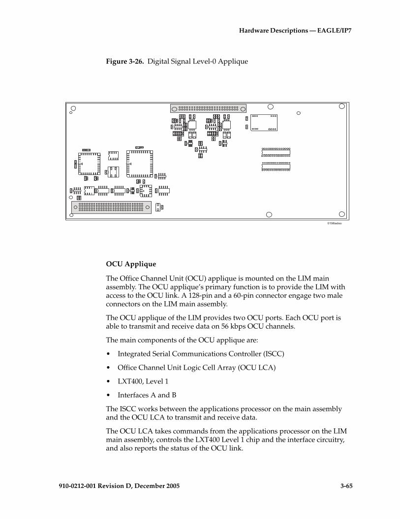
Hardware Descriptions — EAGLE/IP7
910-0212-001 Revision D, December 2005 3-65
Figure 3-26. Digital Signal Level-0 Applique
OCU Applique
The Office Channel Unit (OCU) applique is mounted on the LIM main assembly. The OCU applique’s primary function is to provide the LIM with access to the OCU link. A 128-pin and a 60-pin connector engage two male connectors on the LIM main assembly.
The OCU applique of the LIM provides two OCU ports. Each OCU port is able to transmit and receive data on 56 kbps OCU channels.
The main components of the OCU applique are:
• Integrated Serial Communications Controller (ISCC)
• Office Channel Unit Logic Cell Array (OCU LCA)
• LXT400, Level 1
• Interfaces A and B
The ISCC works between the applications processor on the main assembly and the OCU LCA to transmit and receive data.
The OCU LCA takes commands from the applications processor on the LIM main assembly, controls the LXT400 Level 1 chip and the interface circuitry, and also reports the status of the OCU link.
.�< ����
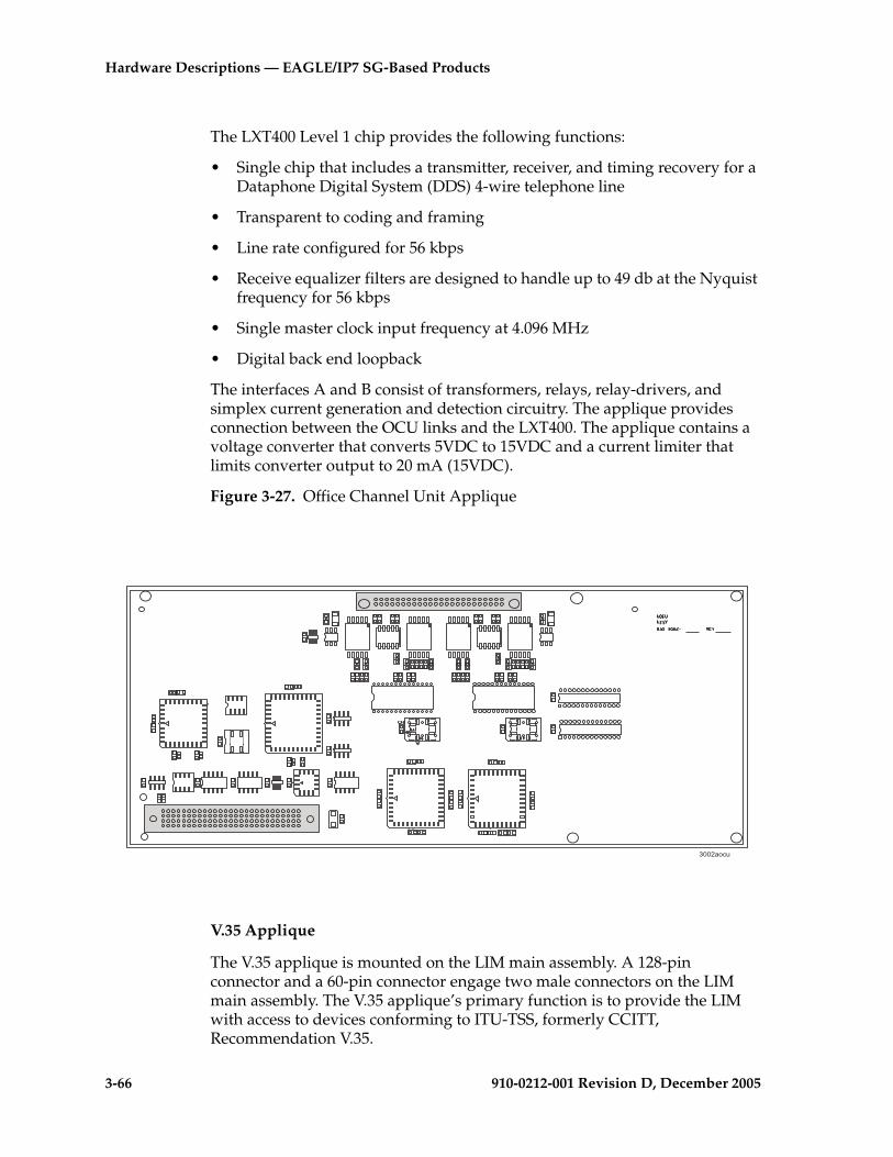
3-66 910-0212-001 Revision D, December 2005
Hardware Descriptions — EAGLE/IP7 SG-Based Products
The LXT400 Level 1 chip provides the following functions:
• Single chip that includes a transmitter, receiver, and timing recovery for a Dataphone Digital System (DDS) 4-wire telephone line
• Transparent to coding and framing
• Line rate configured for 56 kbps
• Receive equalizer filters are designed to handle up to 49 db at the Nyquist frequency for 56 kbps
• Single master clock input frequency at 4.096 MHz
• Digital back end loopback
The interfaces A and B consist of transformers, relays, relay-drivers, and simplex current generation and detection circuitry. The applique provides connection between the OCU links and the LXT400. The applique contains a voltage converter that converts 5VDC to 15VDC and a current limiter that limits converter output to 20 mA (15VDC).
Figure 3-27. Office Channel Unit Applique
V.35 Applique
The V.35 applique is mounted on the LIM main assembly. A 128-pin connector and a 60-pin connector engage two male connectors on the LIM main assembly. The V.35 applique’s primary function is to provide the LIM with access to devices conforming to ITU-TSS, formerly CCITT, Recommendation V.35.
7..-����

Hardware Descriptions — EAGLE/IP7
910-0212-001 Revision D, December 2005 3-67
The V.35 applique of the LIM provides two V.35 ports that can be configured as Data Terminal Equipment (DTE) or Data Communication Equipment (DCE) and has an independent baud rate generator, which is configured using system administration commands at a terminal. When configured as DTE, Request To Send (RTS) is normally high and Data Terminal Ready (DTR) is normally low. When configured as Data Communication Equipment (DCE), Data Carrier Detect (DCD) Receive Line Signal Detect (RLSD) is normally high, while Data Set Ready (DSR) and Clear To Send (CTS) are normally low.
An Integrated Serial Communications Controller (ISCC) is used as the link’s controller. The application microprocessor on the LIM main assembly controls the ISCC.
The LIM V.35 applique supports baud rates of 56 kbps and 64 kbps.Figure 3-28 shows the V.35 applique.
Figure 3-28. V.35 Applique
Application Interface Applique
The Application Interface (AINF) applique is mounted on the LIM main assembly. A 128-pin connector and a 60-pin connector engage two male connectors on the LIM main assembly. The AINF combines on a single applique interfaces to DS0A, OCU, or V.35 links.
The AINF applique of the LIM provides one or two OCU, DS0A, or V.35 interfaces for SS7 links. The type of interface provided by the AINF applique is specified by the ent-card command (refer to the Commands Manual) that is entered during the configuration of the system.
0279av35
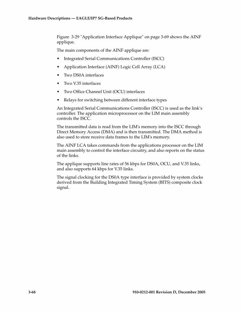
3-68 910-0212-001 Revision D, December 2005
Hardware Descriptions — EAGLE/IP7 SG-Based Products
Figure 3-29 "Application Interface Applique" on page 3-69 shows the AINF applique.
The main components of the AINF applique are:
• Integrated Serial Communications Controller (ISCC)
• Application Interface (AINF) Logic Cell Array (LCA)
• Two DS0A interfaces
• Two V.35 interfaces
• Two Office Channel Unit (OCU) interfaces
• Relays for switching between different interface types
An Integrated Serial Communications Controller (ISCC) is used as the link’s controller. The application microprocessor on the LIM main assembly controls the ISCC.
The transmitted data is read from the LIM's memory into the ISCC through Direct Memory Access (DMA) and is then transmitted. The DMA method is also used to store receive data frames to the LIM's memory.
The AINF LCA takes commands from the applications processor on the LIM main assembly to control the interface circuitry, and also reports on the status of the links.
The applique supports line rates of 56 kbps for DS0A, OCU, and V.35 links, and also supports 64 kbps for V.35 links.
The signal clocking for the DS0A type interface is provided by system clocks derived from the Building Integrated Timing System (BITS) composite clock signal.
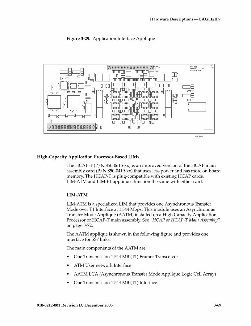
Hardware Descriptions — EAGLE/IP7
910-0212-001 Revision D, December 2005 3-69
Figure 3-29. Application Interface Applique
High-Capacity Application Processor-Based LIMs
The HCAP-T (P/N 850-0615-xx) is an improved version of the HCAP main assembly card (P/N 850-0419-xx) that uses less power and has more on-board memory. The HCAP-T is plug-compatible with existing HCAP cards. LIM-ATM and LIM-E1 appliques function the same with either card.
LIM-ATM
LIM-ATM is a specialized LIM that provides one Asynchronous Transfer Mode over T1 Interface at 1.544 Mbps. This module uses an Asynchronous Transfer Mode Applique (AATM) installed on a High Capacity Application Processor or HCAP-T main assembly. See “HCAP or HCAP-T Main Assembly” on page 3-72.
The AATM applique is shown in the following figure and provides one interface for SS7 links.
The main components of the AATM are:
• One Transmission 1.544 MB (T1) Framer Transceiver
• ATM User network Interface
• AATM LCA (Asynchronous Transfer Mode Applique Logic Cell Array)
• One Transmission 1.544 MB (T1) Interface
.78 ���1

3-70 910-0212-001 Revision D, December 2005
Hardware Descriptions — EAGLE/IP7 SG-Based Products
Figure 3-30. AATM Applique (T1)
E1-ATM
E1-ATM LIM provides one Asynchronous Transfer Mode over E1 Interface at 2.048 Mbps. This module uses an E1 Asynchronous Transfer Mode Applique (E1-ATM) installed on a High Capacity Application Processor (HCAP or HCAP-T) main assembly. The E1-ATM applique provides a new communications capability on the EAGLE, a High Speed Link (HSL) using ATM over E1.
The E1-ATM capability supports a single ATM Virtual Channel Connection (VCC) at a line speed of 2.048 Mbps. To the GLS, LSL LIM, SLAN and SCCP cards, the E1-ATM card looks and operates similar to any other LIM but has increased data throughput. The E1-ATM can perform gateway screening, copy and redirect, conversion and any of the other EAGLE features that an ANSI LIM can perform with the exception of Link Fault Sectionalization (LFS) which is not a requirement for E1 links.
The E1-ATM applique is based upon the ATMANSI feature, which provided ATM communications over T1 links. The E1-ATM supports (2.048 Mbps) link speed instead of T1 link speed (1.544 Mbps), and ITU protocol support instead of ANSI protocols. See the following Figure 3-31 and Figure 3-32 "HCAP Main Assembly (P/N 850-0419-xx)" on page 3-73.
The E1-ATM applique provides one interface for SS7 links.
;,.�.9-9�.-�����
��
��
��

Hardware Descriptions — EAGLE/IP7
910-0212-001 Revision D, December 2005 3-71
The main components of the E1-ATM are:
• One Transmission 2.048 MBps (E1) Framer Transceiver
• ATM User network Interface
• One Transmission 2.048 MBps (E1) Interface
Figure 3-31. E1-ATM Applique
;,.�.9-9�.-�����
��
��
��

3-72 910-0212-001 Revision D, December 2005
Hardware Descriptions — EAGLE/IP7 SG-Based Products
HCAP or HCAP-T Main Assembly
The High-Capacity Application Processor (P/N 850-0419-xx) or HCAP-T (P/N 850-0615-xx) provides the interface between the IMT bus and LIM-ATM or E1-ATM appliques.
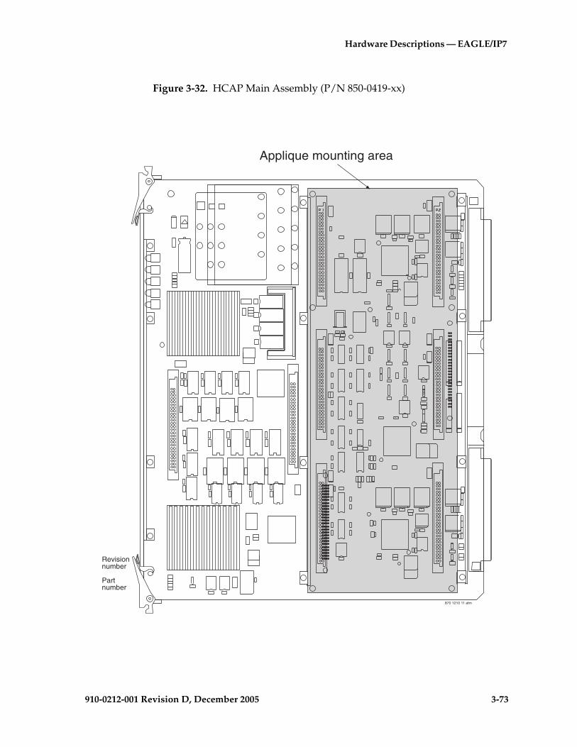
Hardware Descriptions — EAGLE/IP7
910-0212-001 Revision D, December 2005 3-73
Figure 3-32. HCAP Main Assembly (P/N 850-0419-xx)
870 1210 11 atm
Revisionnumber
Partnumber
Applique mounting area
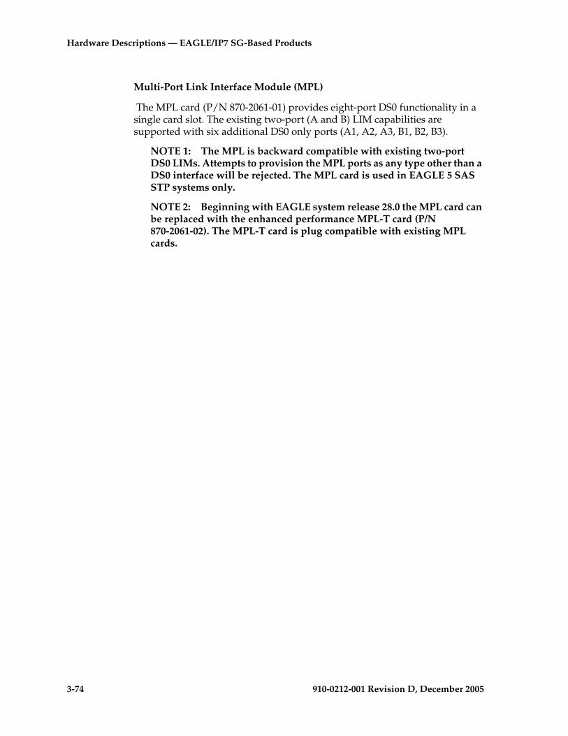
3-74 910-0212-001 Revision D, December 2005
Hardware Descriptions — EAGLE/IP7 SG-Based Products
Multi-Port Link Interface Module (MPL)
The MPL card (P/N 870-2061-01) provides eight-port DS0 functionality in a single card slot. The existing two-port (A and B) LIM capabilities are supported with six additional DS0 only ports (A1, A2, A3, B1, B2, B3).
NOTE 1: The MPL is backward compatible with existing two-port DS0 LIMs. Attempts to provision the MPL ports as any type other than a DS0 interface will be rejected. The MPL card is used in EAGLE 5 SAS STP systems only.
NOTE 2: Beginning with EAGLE system release 28.0 the MPL card can be replaced with the enhanced performance MPL-T card (P/N 870-2061-02). The MPL-T card is plug compatible with existing MPL cards.
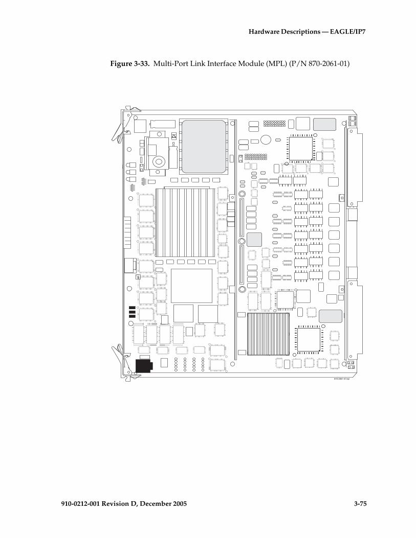
Hardware Descriptions — EAGLE/IP7
910-0212-001 Revision D, December 2005 3-75
Figure 3-33. Multi-Port Link Interface Module (MPL) (P/N 870-2061-01)
870-2061-01mpl
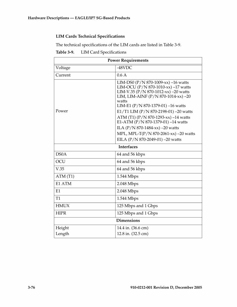
3-76 910-0212-001 Revision D, December 2005
Hardware Descriptions — EAGLE/IP7 SG-Based Products
LIM Cards Technical Specifications
The technical specifications of the LIM cards are listed in Table 3-9.
Table 3-9. LIM Card Specifications
Power Requirements
Voltage -48VDC
Current 0.6 A
Power
LIM-DS0 (P/N 870-1009-xx) –16 wattsLIM-OCU (P/N 870-1010-xx) –17 wattsLIM-V.35 (P/N 870-1012-xx) –20 wattsLIM, LIM-AINF (P/N 870-1014-xx) –20 wattsLIM-E1 (P/N 870-1379-01) –16 wattsE1/T1 LIM (P/N 870-2198-01) –20 wattsATM (T1) (P/N 870-1293-xx) –14 wattsE1-ATM (P/N 870-1379-01) –14 wattsILA (P/N 870-1484-xx) –20 wattsMPL, MPL-T(P/N 870-2061-xx) –20 wattsEILA (P/N 870-2049-01) –20 watts
Interfaces
DS0A 64 and 56 kbps
OCU 64 and 56 kbps
V.35 64 and 56 kbps
ATM (T1) 1.544 Mbps
E1 ATM 2.048 Mbps
E1 2.048 Mbps
T1 1.544 Mbps
HMUX 125 Mbps and 1 Gbps
HIPR 125 Mbps and 1 Gbps
Dimensions
HeightLength
14.4 in. (36.6 cm)12.8 in. (32.5 cm)
Hardware Descriptions — EAGLE/IP7
910-0212-001 Revision D, December 2005 3-77
Database Communications Module and Database Service Module
The Database Communications Module (DCM) provides the following functions for the system:
• Signaling Transfer Point, Local Area Network (SLAN) function
• ISUP protocol data exchange between the IMT and the IP network
• SS7 traffic exchange between B,C,D links and the IP network
• Enhanced bulk download
• GR-376 interface
• When configured as a Sentinel Transport Card (STC) provides TCP/IP interfaces to the Extended Services Platform (ESP).
• When configured as an IPLIMx provides a point to point TCP/IP connection to be used to carry SS7 traffic over B, C and D links. This feature will allow multiple point to point connections and not point to multi-point connections. Point to multi-point connectivity is provided by the SS7IPGW GPL.
The DCM card (P/N 870-1984-01) is the base for the DCM card and has the same size and provisioning requirements. The DCM card also supports one to four plugable memory cards. The primary board DCM with the addition of memory boards and software creates the Database Service Modules (DSMs).
The DCM card and DSM card can be mounted in the control shelf, require two slots for mounting, and must be assigned to an odd numbered slots with the next higher-numbered even slot left open. The DCM card and the DSM card are compatible with control shelf backplanes (P/N 850-0330-03/04/05/06) and extension backplanes (P/N 850-0356-01/02/03/04).
A DCM card is shown in Figure 3-34 "Database Communications Module" on page 3-78 and a DSM card is shown in Figure 3-35 "DSMs with Memory Boards" on page 3-80.
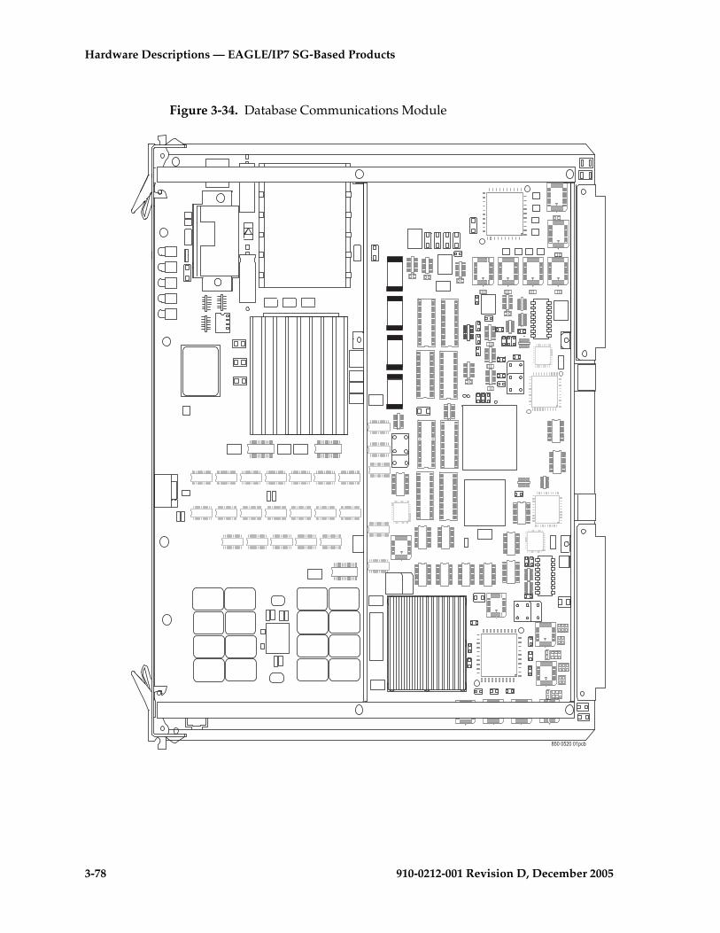
3-78 910-0212-001 Revision D, December 2005
Hardware Descriptions — EAGLE/IP7 SG-Based Products
Figure 3-34. Database Communications Module
;,..,-..�*�"
Hardware Descriptions — EAGLE/IP7
910-0212-001 Revision D, December 2005 3-79
Database Service Module
In the EAGLE 5 SAS STP system primary board DCMX (P/N 870-1984-01) plus memory boards equal Database Service Modules (DSMs). Memory Boards are stacked as indicated in Figure 3-35P/N 870-1984-02 DSM-1GP/N 870-1984-03 DSM-2GP/N 870-1984-04 DSM-3GP/ N 870-1984-05 DSM-4G
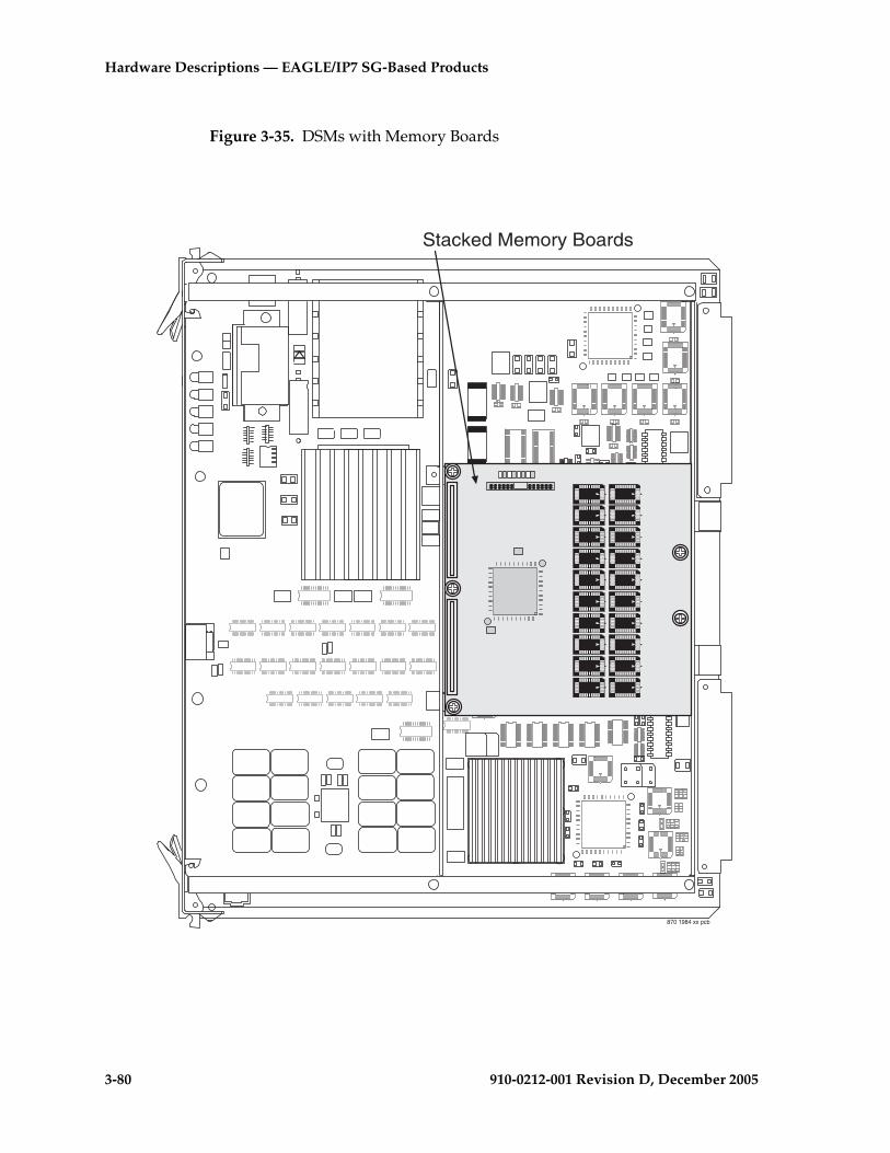
3-80 910-0212-001 Revision D, December 2005
Hardware Descriptions — EAGLE/IP7 SG-Based Products
Figure 3-35. DSMs with Memory Boards
870 1984 xx pcb
Stacked Memory Boards
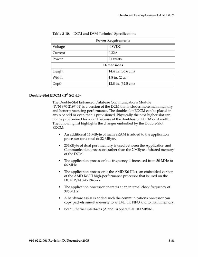
Hardware Descriptions — EAGLE/IP7
910-0212-001 Revision D, December 2005 3-81
Double-Slot EDCM (IP7 SG 4.0)
The Double-Slot Enhanced Database Communications Module (P/N 870-2197-01) is a version of the DCM that includes more main memory and better processing performance. The double-slot EDCM can be placed in any slot odd or even that is provisioned. Physically the next higher slot can not be provisioned for a card because of the double-slot EDCM card width. The following list highlights the changes embodied by the Double-Slot EDCM:
• An additional 16 MByte of main SRAM is added to the application processor for a total of 32 MByte.
• 256KByte of dual port memory is used between the Application and Communication processors rather than the 2 MByte of shared memory of the DCM.
• The application processor bus frequency is increased from 50 MHz to 66 MHz.
• The application processor is the AMD K6-IIIe+, an embedded version of the AMD K6-III high-performance processor that is used on the DCM P/N 870-1945-xx.
• The application processor operates at an internal clock frequency of 396 MHz.
• A hardware assist is added such the communications processor can copy packets simultaneously to an IMT Tx FIFO and to main memory.
• Both Ethernet interfaces (A and B) operate at 100 MByte.
Table 3-10. DCM and DSM Technical Specifications
Power Requirements
Voltage -48VDC
Current 0.32A
Power 21 watts
Dimensions
Height 14.4 in. (36.6 cm)
Width 1.8 in. (2 cm)
Depth 12.8 in. (32.5 cm)

3-82 910-0212-001 Revision D, December 2005
Hardware Descriptions — EAGLE/IP7 SG-Based Products
The following elements of the Double-Slot EDCM are unchanged from the DCM:
• The Double-Slot EDCM requires two frame slots, just like the DCM.
• The communication processor is unchanged.
• The amount of communication processor main memory is unchanged (2MB).
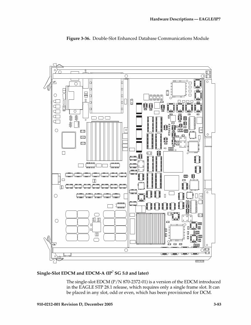
Hardware Descriptions — EAGLE/IP7
910-0212-001 Revision D, December 2005 3-83
Figure 3-36. Double-Slot Enhanced Database Communications Module
Single-Slot EDCM and EDCM-A (IP7 SG 5.0 and later)
The single-slot EDCM (P/N 870-2372-01) is a version of the EDCM introduced in the EAGLE STP 28.1 release, which requires only a single frame slot. It can be placed in any slot, odd or even, which has been provisioned for DCM.
edcm ds pcb

3-84 910-0212-001 Revision D, December 2005
Hardware Descriptions — EAGLE/IP7 SG-Based Products
Figure 3-37. Single-Slot Enhanced Database Communications Module
870-2372-01ssedcm
RE
V X
X
TEKELEC
ED
CM
870-
2372
-01
APPLPROC
IMT A
IMT B
PORT A
PORT B
JTA
G

Hardware Descriptions — EAGLE/IP7
910-0212-001 Revision D, December 2005 3-85
The single-slot EDCM is the base for the following card types:
• Sentinel transport card (STC) (EAGLE 5 SAS STP 28.1 and later)
• General Purpose Service Module (GPSM-II)
• Measurements Collection and Polling Module (MCPM)
• IPLIMx feature with eight point capabilities
• IPGW
EDCM-A Replacement Cards
Beginning with EAGLE Release 34.0, any EDCM cards that need to be replaced will be replaced with EDCM-A cards (P/N 870-2508-01). The front of the card and LEDs are the same as the EDCM card. The following performance parameters are applicable for the EDCM-A:
• STC - No change from EDCM (870-2372-01)
• STPLAN - No change from the EDCM (870-2372-01)
• IPLIMx:
IPLIMx M2PA performance on the EDCM-A (870-2508-01) card can only be guaranteed under the following conditions:
– 2,000 Transactions/Second (TPS)
– Up to 4 Associations
– Average MSU size of 140 Bytes or less.
If the number of associations or average MSU size is increased above these limits, then performance may fall below 2,000 TPS.
• IPGWx:
IPGWx performance on the EDCM-A (870-2508-01) card can only be guaranteed under the following conditions:
– M3UA and TALI only (SUA protocol is not supported)
– 1,700 TPS
– Up to 8 Connections
– Average MSU size of 140 Bytes or less.
If the number of connections or average MSU size is increased above these limits, then performance may fall below 1,700 TPS.
3-86 910-0212-001 Revision D, December 2005
Hardware Descriptions — EAGLE/IP7 SG-Based Products
To maximize throughput per IPGWx card, Tekelec recommends deployment of the same type of DCM cards within a single linkset. For example, EDCM-A cards in a linkset with only EDCM-A cards, and EDCM (870-2372-01/08) cards in a linkset with only EDCM cards. EDCM-As can be deployed within the same linkset with EDCMs; however, if EDCMs and EDCM-As are mixed in a linkset all IPGWx cards within the linkset should be assumed to have a maximum of 1,700 TPS.
Sentinel Transport Card
The Sentinel Transport Card (STC) is a DCM card with an “eroute” generic program load (GPL) installed. The 28.0 release will be based on a double-slot DCM card, while release 28.1 and later will be based on the single-slot EDCM card. The STC card functions as an IP router between the IMT bus internal to an EAGLE 5 SAS STP and the ethernet networks used to communicate with an associated Sentinel Extended Services Platform (ESP).
NOTE: STCs are required for the EAGLE 5 SAS STP 28.0 and later/Integrated Sentinel 8.0 and later features. The STCs provide the IP interface between the LIM cards on the IMT bus and the Sentinel Extended Services Platform (ESP) subassembly.
For more information see Chapter 5, Hardware Descriptions — Sentinel Products.

Hardware Descriptions — EAGLE/IP7
910-0212-001 Revision D, December 2005 3-87
General Purpose Service Module
On the front edge of the GPSM-II card, there are five Light Emitting Diodes (LED) that provide status. The GPSM-II LEDs have four illumination states: red, amber, green, or off. The Application processor LED is off if -48VDC is not supplied. The Application Processor LED is red while booting, amber while loading, and green when the application is running. The IMT A and B LEDs indicate whether the GPSM-II is active on the A or B buses. IMT LED red—the card is off the bus, IMT LED amber—testing not complete, IMT LED green—the card is active on the bus. The PORT A and PORT B LEDs are not used in the GPSM-II.
NOTE 1: GPSM-IIs are required replacements for the MCAP cards in EAGLE Release 30.0. The installation is done at the factory or by Tekelec Technical Support, not by the customer.
Measurements Collection and Polling Module
Prior to EAGLE 31.6, when combined with two UD1G expansion memory boards in a single-slot assembly, the GPSM-II card functions as Measurement Collection and Polling Module (MCPM)—STP, LNP, INP, G-FLEX, and G-PORT Measurements data with File Transfer protocol (FTP). Beginning with EAGLE release 31.6, the MCPM is an EDSM-2G card with 32 MB FSRAM and 2 GB RAM.
NOTE: The MCPM card is a requirement for the FTP measurements feature. The FTP measurements feature uses the MCPM ethernet ports to transfer measurements information directly to a FTP server.
On the front edge of the MCPM card, there are five Light Emitting Diodes (LED) that provide status. The MCPM LEDs have four illumination states: red, amber, green, or off. The Application processor LED is off if -48VDC is not supplied. The Application Processor LED is red while booting, amber while loading, and green when the application is running. The IMT A and B LEDs indicate whether the MCPM is active on the A or B buses. IMT LED red—the card is off the bus, IMT LED amber—testing not complete, IMT LED green—the card is active on the bus. The PORT A and PORT B LEDs are illuminated green when the A or B port is active.
IPLIMx with Eight-Point Capability
The IPLIMx to eight points feature provides the ability to support up to eight point to point TALI socket connections on an IPLIMx Single-slot EDCM card. Both ANSI and ITU links are supported.

3-88 910-0212-001 Revision D, December 2005
Hardware Descriptions — EAGLE/IP7 SG-Based Products
This feature builds upon on the previous Multipoint IPLIMx feature. The Multipoint IPLIMx feature provided the capability of multiple point to point connections (limited to 2) on an IPLIMx GPL. Multipoint IPLIMx capability was implemented on DCM and double-slot EDCM cards. The IPLIMx to eight Point feature expands the Multipoint IPLIMx capability to support eight signaling link ports. Only SAAL/TALI signaling links are expanded. The presence of any M3UA/SCTP signaling links on an IPLIMx card will result in the enforcement of two signaling links maximum per IPLIMx card.
Application Service Module
The Application Service Module (ASM)(P/N 870-1011-xx), provides additional memory that is used to store translation tables and to screen RMV data used for applications and Gateway Screening (GWS). The ASM consists of a main assembly and one 16 MByte memory applique.
NOTE: Beginning with EAGLE release 31.6 ASM cards will no longer be supported and must be replaced by TSM cards. SCCP, GTT, GWS, and GLS functions will be provided by TSM cards.
The main assembly portion of the ASM contains the following:
An 80486 applications processor.
• An 80386 communications processor that provides a data transmit/receive interface.
• An Inter-processor Message Transport (IMT) interface that provides two 125 Mbps communications links and provides communications between modules.
• A –48VDC/+5VDC and a –48VDC/+3VDC DC to DC power converter.
Obsolescence of ASM Cards
In EAGLE releases prior to 31.6, the only GPLs supported by the ASM card were the GLS and SCCP applications. Beginning with EAGLE 31.6, the SCCP and GLS applications are supported by the TSM card.
In addition, EAGLE 31.6 will Auto-inhibit ASM cards that attempt loading SCCP or GLS applications and reject the upgrade command if any ASMs are present in the system. Upon ASM auto-inhibt, UIM shall be displayed indicating “ASM card type not allowed.”
When performing a system upgrade, a check for provisioned ASM cards will be made on the system at upgrade command initiation. The upgrade command will be rejected with appropriate error message if any ASM cards are found provisioned. All ASM cards must be replaced with TSM Cards prior to upgrade.

Hardware Descriptions — EAGLE/IP7
910-0212-001 Revision D, December 2005 3-89
Applications Processor
The Application Processor (AP) section of the ASM interfaces and controls the operation of the memory applique. The AP operations are controlled by an 80486 processor and peripherals.
The AP interfaces the Communication Processor (CP) to transfer I/O data to and from the IMT buses. Message transfer between the two processors is arbitrated by a 256 kbyte dual memory port.
NOTE: It is Tekelec's recommendation that in systems prior to release 31.6, ASM cards running the SCCP application be uniformly distributed in the EAGLE 5 SAS STP to provide a more even SCCP load distribution. During normal operation unevenly distributed SCCP cards in an EAGLE STP would not have any network or system impacts. However, should a particular SCCP card database(s) become corrupted, inconsistent, or at a different level, depending on the amount of service provided by that card and the extent of the database issue, network impacts can occur.
See the following Figure 3-38, “Application Service Module Main Assembly,” on page 3-90.
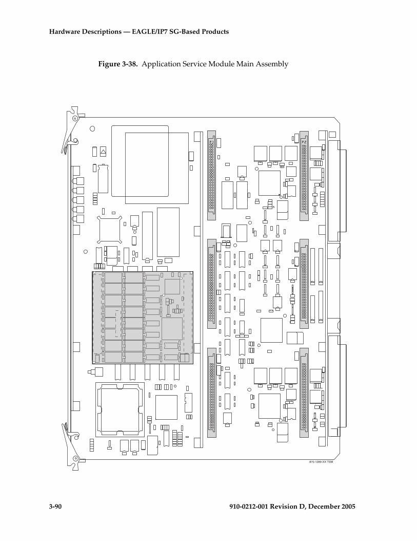
3-90 910-0212-001 Revision D, December 2005
Hardware Descriptions — EAGLE/IP7 SG-Based Products
Figure 3-38. Application Service Module Main Assembly
870-1289-XX TSM

Hardware Descriptions — EAGLE/IP7
910-0212-001 Revision D, December 2005 3-91
Communications Processor
The Communications Processor (CP) is made up of an 80386 microprocessor and peripherals. The CP section of the ASM controls the flow of transmit/receive data to and from the Inter-processor Message Transport IMT buses.
In the receive direction, the CP writes a receive initialization command to the IMT. The data packet is checked for the destination. If its destination is the ASM, the format is checked and a Cyclic Redundancy Check (CRC) is performed. The packet is then transferred to the CP memory by Direct Memory Access (DMA).
In the transmit direction, the CP forwards a packet along with 2 CRC bytes, calculated by the IMT circuitry, to the HIPR (EAGLE 5 SAS STP systems only) for transmission.
The CP also controls the selection of the IMT, A or B. In the other direction, the CP forwards data received from the IMT through the Application Processor (AP) to the interface port connector on the extension shelf backplane.
The CP is interrupt driven. Eight levels of the interrupts initiated by the IMT, the AP, and the Maintenance and Administration Subsystem (MAS) are administered by a Programmable Interrupt Controller (PIC).
Inter-processor Message Transport
Each ASM unit has two Inter-processor Message Transports (IMTs) interface buses, IMT A and IMT B. Each IMT interface circuit provides a direct access to a different 125 Mbps communications link.
In the receive direction, a data packet is checked to see if it is destined for this particular ASM. If it is, the packet is checked for format and a cyclic redundancy check is performed. The packet is then transferred to the CP, 80C386 memory by Direct Memory Access (DMA).
If the packet is not destined for this ASM, it is sent back onto the IMT bus towards the next module.
In the transmit direction, the CRC is calculated for a packet and the packet is transmitted through the HIPR (EAGLE 5 SAS STP systems only) to the IMT bus.
Power Converter Unit
ASM power is provided by a DC to DC converter that converts the –48VDC supplied to the system and the +5VDC needed to power the ASM components. The 80486-equipped ASMs also have a –48VDC/+3VDC DC to DC power converter.

3-92 910-0212-001 Revision D, December 2005
Hardware Descriptions — EAGLE/IP7 SG-Based Products
Memory Applique
The memory applique is attached to the ASM main assembly and comes in two types. The ASM (P/N 870-1011-xx) uses a Dynamic Random Access Memory (DRAM) based applique and the ASM (P/N 870-1143-xx) uses a Static RAM (SRAM) based applique.
The memory applique is mounted on the main assembly. This card expands the memory capacity of the ASM main assembly by providing additional random access memory.
The DRAM memory applique has the capability to correct single bit errors and to detect double bit errors during a memory read cycle. Whenever a single bit error occurs, the byte or word containing that error is automatically corrected and a status bit, which can be read by the software, shows this occurrence. If a double bit error happens, an interrupt is sent to signal the current read operation has failed and the address that holds the corrupted data is available form the software.
The major sections of the memory appliques are shown in Figure 3-39 "Dynamic Random Access Memory Applique" on page 3-93 and Figure 3-40 "Static Random Access Memory Applique" on page 3-93.
Dynamic Random Access Memory (DRAM) applique
• Dynamic Random Access Memory (DRAM)
• DRAM controller
• Error detection and correction
• Control logic
Static Random Access Memory (SRAM) applique
• Static Random Access Memory (SRAM)
• Memory select decode circuits
On the DRAM memory applique, data moves in and out of the DRAM under the direction of the DRAM controller. On the SRAM memory applique, data moves in and out of the SRAM under direction of the memory select decode circuits.
The control logic section controls all functions on the DRAM memory applique. This includes the DRAM controller, the error detection and correction section, and the Light Emitting Diode (LED) drivers, (not currently used). The control logic section receives input from the address and control inputs from the ASM along with input from the error detection and correction section and the DRAM controller. From these inputs, the control logic section sends the appropriate information to the ASM, the DRAM controller, the error detection and correction section, and the DRAM.

Hardware Descriptions — EAGLE/IP7
910-0212-001 Revision D, December 2005 3-93
Figure 3-39. Dynamic Random Access Memory Applique
Figure 3-40. Static Random Access Memory Applique
7..9����
6�
6-
3-39 asm8
J2
J1
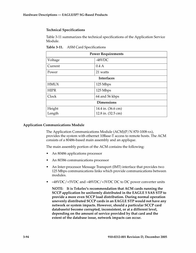
3-94 910-0212-001 Revision D, December 2005
Hardware Descriptions — EAGLE/IP7 SG-Based Products
Technical Specifications
Table 3-11 summarizes the technical specifications of the Application Service Module.
Application Communications Module
The Application Communications Module (ACM)(P/N 870-1008-xx), provides the system with ethernet 10Base-T access to remote hosts. The ACM consists of a 80486-based main assembly and an applique.
The main assembly portion of the ACM contains the following:
• An 80486 applications processor
• An 80386 communications processor
• An Inter-processor Message Transport (IMT) interface that provides two 125 Mbps communications links which provide communications between modules.
• –48VDC/+5VDC and –48VDC/+3VDC DC to DC power converter units
NOTE: It is Tekelec's recommendation that ACM cards running the SCCP application be uniformly distributed in the EAGLE 5 SAS STP to provide a more even SCCP load distribution. During normal operation unevenly distributed SCCP cards in an EAGLE STP would not have any network or system impacts. However, should a particular SCCP card database(s) become corrupted, inconsistent, or at a different level, depending on the amount of service provided by that card and the extent of the database issue, network impacts can occur.
Table 3-11. ASM Card Specifications
Power Requirements
Voltage -48VDC
Current 0.4 A
Power 21 watts
Interfaces
HMUX 125 Mbps
HIPR 125 Mbps
Clock 64 and 56 kbps
Dimensions
HeightLength
14.4 in. (36.6 cm)12.8 in. (32.5 cm)

Hardware Descriptions — EAGLE/IP7
910-0212-001 Revision D, December 2005 3-95
Figure 3-41 "Application Communications Module Main Assembly" on page 3-95 shows the ACM card main assembly.
Figure 3-41. Application Communications Module Main Assembly
870-1289-XX TSM

3-96 910-0212-001 Revision D, December 2005
Hardware Descriptions — EAGLE/IP7 SG-Based Products
Ethernet Applique
The Application Communications Module (ACM) Ethernet applique is attached to the ACM main assembly and provides a communication interface between the ACM and an external host system across an Ethernet LAN. Figure 3-42 "Application Communications Module Ethernet Applique" on page 3-97 shows the applique.
This Ethernet applique receives and transmits signals through a 60-pin application connector on the main assembly. Control of the Ethernet applique is the responsibility of the applications processor. Each ACM is connected, through the backplane, to a single port Media Access Unit (MAU) that is attached to the backplane interface connector for that ACM.
Each applique has a dedicated two-part memory buffer. The top 2K bytes are used as the transmit buffer to stores packets waiting for transmission. The remaining 62K bytes, the receive buffer, is used to receive packets.
Signal manipulation is the responsibility of an Ethernet controller and the supporting components. These components include:
• Ethernet controller—The Ethernet controller is an integrated local area network controller that supports the IEEE 802.3 Carrier Sense Multiple Access CSMA/10 Mbps protocols. This Ethernet controller equips the buffer manager, which arbitrates data access to its dedicated 64K bytes of Dynamic Random Access Memory (DRAM).
• Ethernet Encoder/Decoder (EED)—The EED functions to provide the encoding or decoding of the IEEE Ethernet signals. This circuit also features collision and carrier detection.
• Memory buffers.
• The Ethernet applique receives +5VDC from the ACM main assembly. A DC to DC converter produces +12V from the +5VDC to power the MAU.
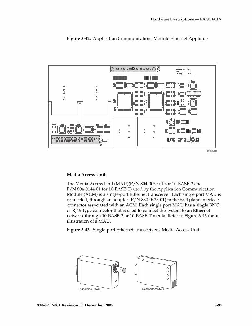
Hardware Descriptions — EAGLE/IP7
910-0212-001 Revision D, December 2005 3-97
Figure 3-42. Application Communications Module Ethernet Applique
Media Access Unit
The Media Access Unit (MAU)(P/N 804-0059-01 for 10-BASE-2 and P/N 804-0144-01 for 10-BASE-T) used by the Application Communication Module (ACM) is a single-port Ethernet transceiver. Each single port MAU is connected, through an adapter (P/N 830-0425-01) to the backplane interface connector associated with an ACM. Each single port MAU has a single BNC or RJ45-type connector that is used to connect the system to an Ethernet network through 10-BASE-2 or 10-BASE-T media. Refer to Figure 3-43 for an illustration of a MAU.
Figure 3-43. Single-port Ethernet Transceivers, Media Access Unit
3003AETH
J1
J2
BA
DC
BA
10-BASE-2 MAU 10-BASE-T MAU

3-98 910-0212-001 Revision D, December 2005
Hardware Descriptions — EAGLE/IP7 SG-Based Products
Application Processor
The Application Processor (AP) section of the ACM interfaces and controls the operation of the Ethernet applique.
The AP interfaces the Communication Processor (CP) to transfer interface data to and from the IMT buses. Message transfer between the two processors is arbitrated by a 256 kbyte dual memory port.
Communication Processor
The Communication Processor (CP) is made up of an 80386 processor and peripherals. The CP section of the ACM controls the flow of transmit/receive data to and from the IMT buses.
In the receive direction, the CP writes a receive initialization command to the IMT. The data packet is checked for the destination. If its destination is this ACM, the format is checked and a Cyclic Redundancy Check (CRC) is performed. The packet is then transferred to the CP memory by Direct Memory Access (DMA).
In the transmit direction, the CP forwards a packet along with 2 CRC bytes, calculated by the IMT circuitry, to the HIPR (EAGLE 5 SAS STP only) for transmission.
The CP also controls the selection of the IMT, A or B. In the other direction, the CP forwards data received from the IMT through the AP to the interface port DB15 connector on the extension shelf backplane.
The CP is interrupt driven. Eight levels of the interrupts initiated by the IMT, the AP, and the MAS, are administered by a Programmable Interrupt Controller (PIC).
Inter-processor Message Transport
Each Application Communication Module (ACM) unit has two Inter-processor Message Transport (IMT) interface circuits, IMT A and IMT B. Each IMT interface circuit provides a direct access to another 125 Mbps communications link.
In the receive direction, a data packet is checked to see if it is destined for this particular ACM. If it is, the packet is checked for format and a cyclic redundancy check is performed. The packet is next transferred to the CP (80C386) memory by Direct Memory Access (DMA).
If the packet is not destined for this ACM, it is sent back onto the IMT bus towards the next module.

Hardware Descriptions — EAGLE/IP7
910-0212-001 Revision D, December 2005 3-99
In the transmit direction, the Cyclic Redundancy Check (CRC) is calculated for a packet, and the packet is transmitted through the HIPR (EAGLE 5 SAS STP systems only) to the Inter-processor Message Transport (IMT) bus.
Power Converter Unit
ACM power is provided by two DC to DC converters that convert the –48VDC supplied to the system to +5VDC and +3VDC needed to power the ACM components.
Test and Maintenance Features
Colored LEDs are mounted on the front edge of the printed circuit board, ACM status and alarm indicators.
ACM Technical Specifications
Table 3-12 summarizes the technical specifications of the Application Communications Module.
Table 3-12. ACM Technical Specifications
Power Requirements
Voltage -48VDC
Current 0.4 A
Power 21 watts
Interfaces
Ethernet 10 Mbps
HMUX 125 Mbps
HIPR 125 Mbps
Clock 64 and 56 kbps
Dimensions
HeightLength
14.4 in. (36.6 cm)12.8 in. (32.5 cm)

3-100 910-0212-001 Revision D, December 2005
Hardware Descriptions — EAGLE/IP7 SG-Based Products
Translation Service Module
The Translation Service Module (TSM) provides translation capability and Global Title Translation (GTT) implementation for the Local Number Portability (LNP) function by means of one or more identically configured cards per STP node. If more than one TSM is provided in each shelf, they must be powered from different fuse positions and power feeds.
The E586 and E586-T primary boards provide all logic required to support the TSM MCAP-256 functions. The E586 functions will include:
• An Applications Processor for MCAP applications in the EAGLE system.
• A Communication Processor for the high speed bus interface (IMT bus).
• Four Expansion Memory Interfaces to allow additional memory for applications.
• An Expansion Bus Interface (EBI) to allow communication with the TDM card in the EAGLE system.
• A Maintenance Bus serial interface.
• A dual port memory to allow information to be passed between the Application and Communications Processors.
• A boot EPROM for initialization software of both the Application and Communications Processors.
TSMs can have one to four M256 memory modules provisioned. Part numbers for the TSMs are:
• TSM with one M256 (P/N 870-1289-xx)
• TSM with two M256 (P/N 870-1290-xx)
• TSM with three M256 (P/N 870-1991-xx)
• TSM with four M256 (P/N 870-1292-xx)
For an illustration of the TSM with one M256 installed refer to Figure 3-44 "Translation Service Module (P/N 870-1289-xx)" on page 3-102. For an illustration of a TSM with four M256s installed refer to Figure 3-45 "Translation Service Module (P/N 870-1292-xx)" on page 3-103.
The main assembly portion of the TSM consists of:
• An 80486DX5 applications processor
• An 80386 communications processor
Hardware Descriptions — EAGLE/IP7
910-0212-001 Revision D, December 2005 3-101
• An Inter-processor Message Transport (IMT) interface that provides two 125 Mbps communications links providing communications between modules
NOTE: It is Tekelec's recommendation that cards running the SCCP application be uniformly distributed in the EAGLE 5 SAS STP to provide a more even SCCP load distribution. During normal operation unevenly distributed SCCP cards in an EAGLE STP would not have any network or system impacts. However, should a particular SCCP card database(s) become corrupted, inconsistent, or at a different level, depending on the amount of service provided by that card and the extent of the database issue, network impacts can occur.

3-102 910-0212-001 Revision D, December 2005
Hardware Descriptions — EAGLE/IP7 SG-Based Products
Figure 3-44. Translation Service Module (P/N 870-1289-xx)
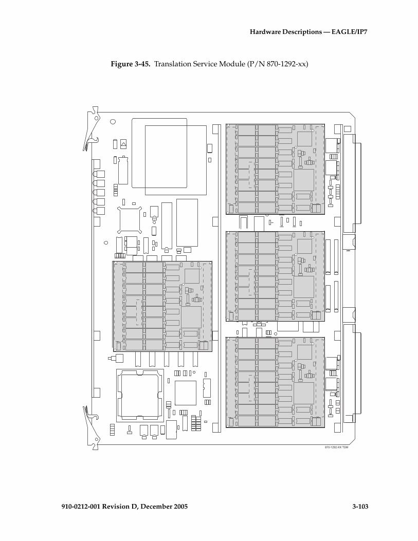
Hardware Descriptions — EAGLE/IP7
910-0212-001 Revision D, December 2005 3-103
Figure 3-45. Translation Service Module (P/N 870-1292-xx)
�����������

3-104 910-0212-001 Revision D, December 2005
Hardware Descriptions — EAGLE/IP7 SG-Based Products
E1 Interface Backplane Module
This section contains a general description of the hardware necessary to support the E1 Interface application. Systems ordered with the E1 Interface will have this hardware installed at the factory.
The E1/Channel applique provides a physical interface to the system. The applique terminates or distributes E1 facility signals for the purpose of processing the SS7 signaling links carried by the E1 carrier. The applique can be configured as an E1 card or as a channel card, as shown in Figure 3-46 "E1 Card (P/N 870-1379-xx)" on page 3-104. The implementation is configured by way of switch settings on the applique.
Figure 3-46. E1 Card (P/N 870-1379-xx)
870 1210 14 e1
0 1
2 3
4 5
6 7
8 9
0123
4567
89R
EV
XX
LIM
-E1
870-
1210
-14
APPLPROC
IMTA
IMTB
PORT A
PORT B
Serialnumber
CLEIcode
Revisionnumber
Partnumber
TEKELEC
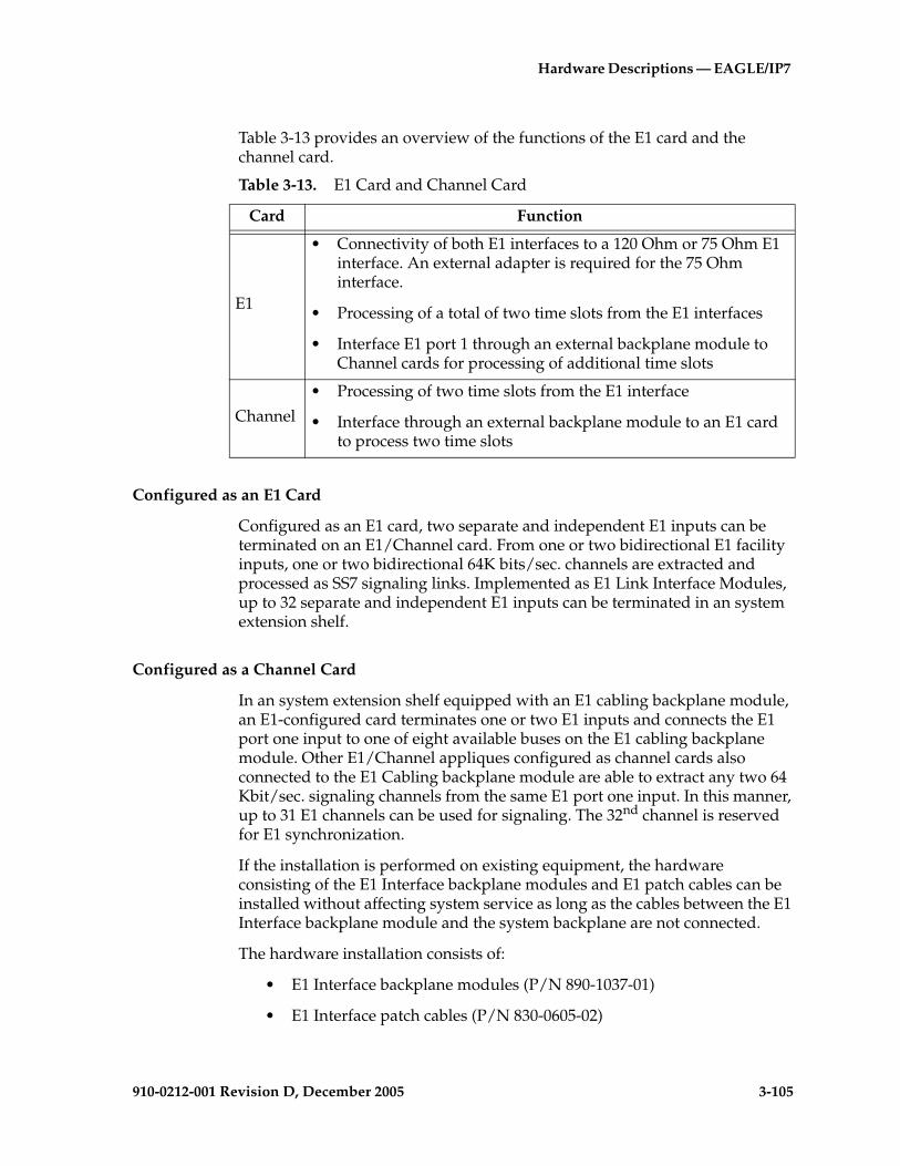
Hardware Descriptions — EAGLE/IP7
910-0212-001 Revision D, December 2005 3-105
Table 3-13 provides an overview of the functions of the E1 card and the channel card.
Configured as an E1 Card
Configured as an E1 card, two separate and independent E1 inputs can be terminated on an E1/Channel card. From one or two bidirectional E1 facility inputs, one or two bidirectional 64K bits/sec. channels are extracted and processed as SS7 signaling links. Implemented as E1 Link Interface Modules, up to 32 separate and independent E1 inputs can be terminated in an system extension shelf.
Configured as a Channel Card
In an system extension shelf equipped with an E1 cabling backplane module, an E1-configured card terminates one or two E1 inputs and connects the E1 port one input to one of eight available buses on the E1 cabling backplane module. Other E1/Channel appliques configured as channel cards also connected to the E1 Cabling backplane module are able to extract any two 64 Kbit/sec. signaling channels from the same E1 port one input. In this manner, up to 31 E1 channels can be used for signaling. The 32nd channel is reserved for E1 synchronization.
If the installation is performed on existing equipment, the hardware consisting of the E1 Interface backplane modules and E1 patch cables can be installed without affecting system service as long as the cables between the E1 Interface backplane module and the system backplane are not connected.
The hardware installation consists of:
• E1 Interface backplane modules (P/N 890-1037-01)
• E1 Interface patch cables (P/N 830-0605-02)
Table 3-13. E1 Card and Channel Card
Card Function
E1
• Connectivity of both E1 interfaces to a 120 Ohm or 75 Ohm E1 interface. An external adapter is required for the 75 Ohm interface.
• Processing of a total of two time slots from the E1 interfaces
• Interface E1 port 1 through an external backplane module to Channel cards for processing of additional time slots
Channel
• Processing of two time slots from the E1 interface
• Interface through an external backplane module to an E1 card to process two time slots
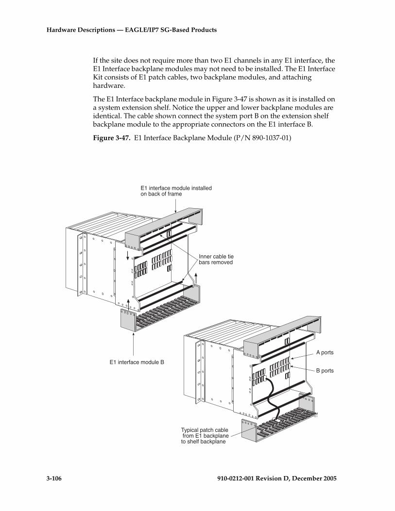
3-106 910-0212-001 Revision D, December 2005
Hardware Descriptions — EAGLE/IP7 SG-Based Products
If the site does not require more than two E1 channels in any E1 interface, the E1 Interface backplane modules may not need to be installed. The E1 Interface Kit consists of E1 patch cables, two backplane modules, and attaching hardware.
The E1 Interface backplane module in Figure 3-47 is shown as it is installed on a system extension shelf. Notice the upper and lower backplane modules are identical. The cable shown connect the system port B on the extension shelf backplane module to the appropriate connectors on the E1 interface B.
Figure 3-47. E1 Interface Backplane Module (P/N 890-1037-01)
e-1
Typical patch cable from E1 backplaneto shelf backplane
E1 interface module B
E1 interface module installedon back of frame
Inner cable tiebars removed
A ports
B ports

Hardware Descriptions — EAGLE/IP7
910-0212-001 Revision D, December 2005 3-107
External Interface Descriptions
The E1 Interface backplane module provides a method for extending individual E1 channels from the E1-configured cards to any channel-configured cards in use.
NOTE: The following issues regarding the E1 backplane module:
• Only one E1 trunk can be terminated on each bus on the backplane module.
• When installing non-E1 cards on the shelf equipped with the E1 interface backplane module, ensure that none of the slots to be used are cabled to the backplane module. If a non-E1 card is installed in a slot that is connected to the E1 backplane module, all E1 cards on that bus may fail.
The E1 backplane module is impedance-controlled for 120 Ohms and is designed for use with RS-485 transmission characteristics.
Possible Configurations
The E1 backplane module was designed to allow the maximum number of possible customer setups. It allows the customer to choose between several levels of diversity and convenience. Configurations depend on the number of cards configured as E1 cards versus the number of cards configured as channel cards. The level of diversity required by the customer also affects the configuration requirements. All signals labeled “E1 input” may be one or two E1 ports depending on the cable used.
High Level Functional Description
The E1 interface backplane module provides a connection point from the system backplane to an external E1 interface. The backplane module is populated with 64 high density connectors and 64 terminating resistors. For a method of connecting the backplane module and possible configurations on the board (refer to Figure 3-50 "E1 Interface Backplane Module Connector Diagram" on page 3-111). Notice that each row is bused together and each column lines up with a system slot. Also note there are always two E1 backplane modules available at the rear of the system shelf. The upper and lower backplane modules are identical. Refer to Figure 3-48 "E1 Backplane Module and Screws and Washers" on page 3-108.
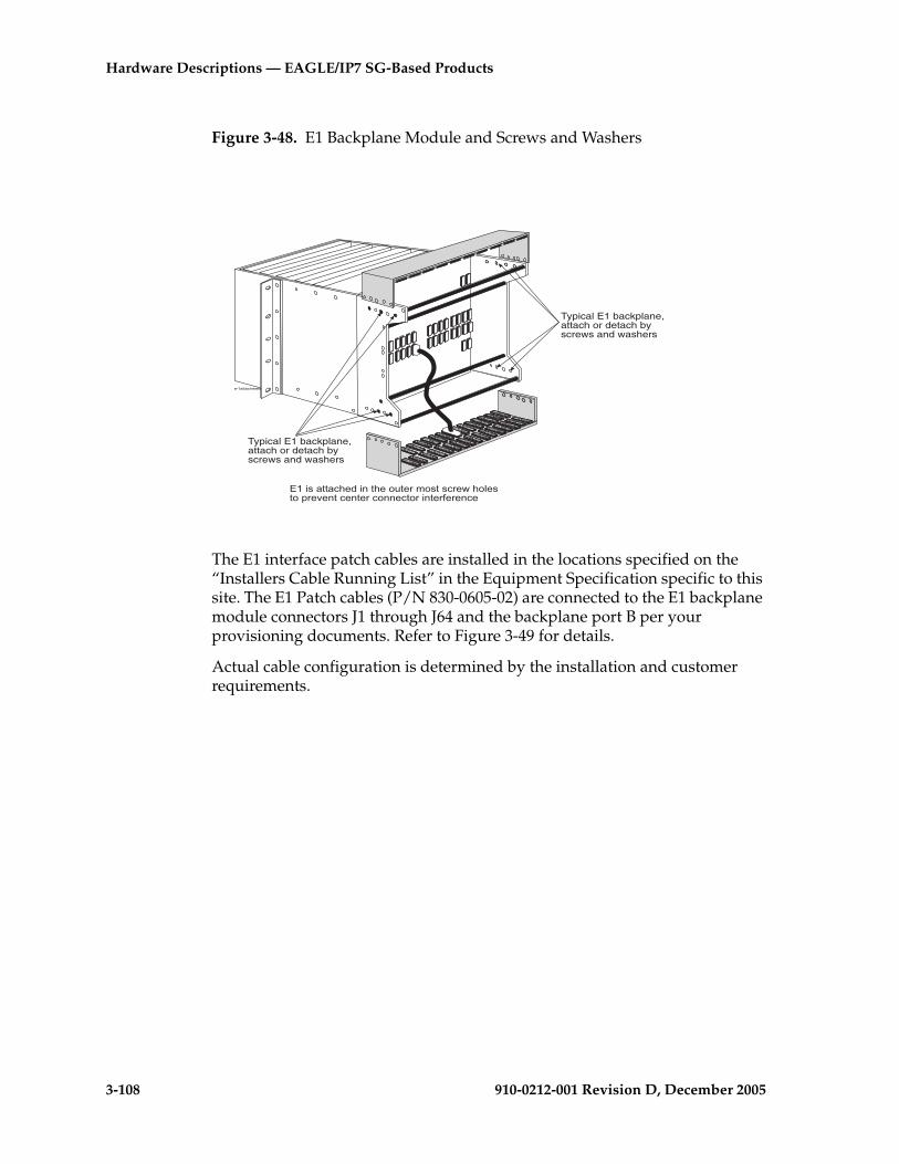
3-108 910-0212-001 Revision D, December 2005
Hardware Descriptions — EAGLE/IP7 SG-Based Products
Figure 3-48. E1 Backplane Module and Screws and Washers
The E1 interface patch cables are installed in the locations specified on the “Installers Cable Running List” in the Equipment Specification specific to this site. The E1 Patch cables (P/N 830-0605-02) are connected to the E1 backplane module connectors J1 through J64 and the backplane port B per your provisioning documents. Refer to Figure 3-49 for details.
Actual cable configuration is determined by the installation and customer requirements.
Typical E1 backplane,attach or detach byscrews and washers
Typical E1 backplane,attach or detach byscrews and washers
e-1attachment
������������� ��!�����"#��$�%"�����$�&��"'���"�($�)�!����!��$��"!!���"$��!��$*�$�!��

Hardware Descriptions — EAGLE/IP7
910-0212-001 Revision D, December 2005 3-109
����������� ������ ������ ������ ������ ������ ������ ������ ����� ����� ����� ����� ����� ����� �����
����������� ������ ������ ������ ������ ������ ������ ������ ����� ����� ����� ����� ����� ����� �����
�������
�������
�������
�������
�������
�������
�������
�������
�������
�������
�������
�������
�������
�������
�������
�������
����������� ������ ������ ������ ������ ������ ������ ������ ����� ����� ����� ����� ����� ����� �����
����������� ������ ������ ������ ������ ������ ������ ������ ����� ����� ����� ����� ����� ����� �����
�� �� �� �� �� �� �� �� �� ��� ��� ��� ������ ��� ���
��� ��� ��� ��� ��� ��� ��� ��� ��� ��� ��� ��� ��� ��� ��� ���
��� ��� ��� ��� ��� ��� ��� ��� ��� ��� ��� ��� ��� ��� ��� ���
��� ��� ��� ��� ��� ��� ��� ��� ��� ��� ��� ��� ��� ��� ������
����������� ������ ������ ������ ������ ������ ������ ������ ����� ����� ����� ����� ����� ����� �����
����������� ������ ������ ������ ������ ������ ������ ������ ����� ����� ����� ����� ����� ����� �����
�� �� �� �� �� �� �� �� �� ��� ��� ��� ������ ��� ���
��� ��� ��� ��� ��� ��� ��� ��� ��� ��� ��� ��� ��� ��� ��� ���
��� ��� ��� ��� ��� ��� ��� ��� ��� ��� ��� ��� ��� ��� ��� ���
��� ��� ��� ��� ��� ��� ��� ��� ��� ��� ��� ��� ��� ��� ������
����
����!
����!
����!
����!
����!
����!
����!
����!
����!
����!
����!
����!
����!
����!
����!
����!
����
����
����
����
����
����
����
����
����
����
����
����
����
����
����
"�#����$�%&�����
'������$�%&�����
�()��*�+���)���)���,
� �� �� �� � � �� �� �� �
Figure 3-49. E1 Backplane Modules Patch Cables
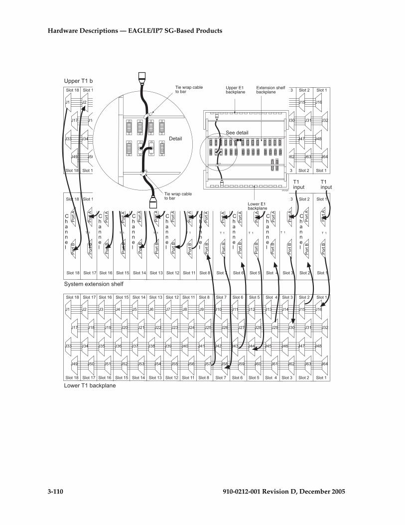
3-110 910-0212-001 Revision D, December 2005
Hardware Descriptions — EAGLE/IP7 SG-Based Products
����������� ������ ������ ������ ������ ������ ������ ������ ����� ����� ����� ����� ����� ����� �����
����������� ������ ������ ������ ������ ������ ������ ������ ����� ����� ����� ����� ����� ����� �����
�������
�������
�������
�������
�������
�������
�������
�������
�������
�������
�������
�������
�������
�������
�������
�������
����������� ������ ������ ������ ������ ������ ������ ������ ����� ����� ����� ����� ����� ����� �����
����������� ������ ������ ������ ������ ������ ������ ������ ����� ����� ����� ����� ����� ����� �����
�� �� �� �� �� �� �� �� �� ��� ��� ��� ������ ��� ���
��� ��� ��� ��� ��� ��� ��� ��� ��� ��� ��� ��� ��� ��� ��� ���
��� ��� ��� ��� ��� ��� ��� ��� ��� ��� ��� ��� ��� ��� ��� ���
��� ��� ��� ��� ��� ��� ��� ��� ��� ��� ��� ��� ��� ��� ������
����������� ������ ������ ������ ������ ������ ������ ������ ����� ����� ����� ����� ����� ����� �����
����������� ������ ������ ������ ������ ������ ������ ������ ����� ����� ����� ����� ����� ����� �����
�� �� �� �� �� �� �� �� �� ��� ��� ��� ������ ��� ���
��� ��� ��� ��� ��� ��� ��� ��� ��� ��� ��� ��� ��� ��� ��� ���
��� ��� ��� ��� ��� ��� ��� ��� ��� ��� ��� ��� ��� ��� ��� ���
��� ��� ��� ��� ��� ��� ��� ��� ��� ��� ��� ��� ��� ��� ������
����
����!
����!
����!
����!
����!
����!
����!
����!
����!
����!
����!
����!
����!
����!
����!
����!
����
����
����
����
����
����
����
����
����
����
����
����
����
����
����
"�#����$�%&�����
'������$�%&�����
�()��*�+���)���)���,
� �� �� �� � � �� �� �� �
�����'
Upper E1backplane
Extension shelfbackplane
Lower E1backplane
Tie wrap cableto bar
Tie wrap cableto bar
���� ����'
e1bckpln

Hardware Descriptions — EAGLE/IP7
910-0212-001 Revision D, December 2005 3-111
Figure 3-50. E1 Interface Backplane Module Connector Diagram
Cabling for T1 is the same as the cabling for E1.
Slot 1Slot 18 Slot 17 Slot 16 Slot 15 Slot 14 Slot 13 Slot 12 Slot 11 Slot 8 Slot 7 Slot 6 Slot 5 Slot 4 Slot 3 Slot 2
Slot 1Slot 18 Slot 17 Slot 16 Slot 15 Slot 14 Slot 13 Slot 12 Slot 11 Slot 8 Slot 7 Slot 6 Slot 5 Slot 4 Slot 3 Slot 2
Channel
E1
Channel
E1
Channel
E1
Channel
E1
Channel
E1
Channel
E1
Channel
E1
Channel
E1
E1input
E1input
E1input
E1input
E1input
E1input
E1input
E1input
Slot 1Slot 18 Slot 17 Slot 16 Slot 15 Slot 14 Slot 13 Slot 12 Slot 11 Slot 8 Slot 7 Slot 6 Slot 5 Slot 4 Slot 3 Slot 2
Slot 1Slot 18 Slot 17 Slot 16 Slot 15 Slot 14 Slot 13 Slot 12 Slot 11 Slot 8 Slot 7 Slot 6 Slot 5 Slot 4 Slot 3 Slot 2
J1 J2 J3 J4 J5 J6 J7 J8 J9 J10 J11 J12 J14J13 J15 J16
J17 J18 J19 J20 J21 J22 J23 J24 J25 J26 J27 J28 J29 J30 J31 J32
J33 J34 J35 J36 J37 J38 J39 J40 J41 J42 J43 J44 J45 J46 J47 J48
J49 J50 J52 J53 J54 J55 J56 J57 J58 J59 J60 J61 J62 J63 J64J51
Slot 1Slot 18 Slot 17 Slot 16 Slot 15 Slot 14 Slot 13 Slot 12 Slot 11 Slot 8 Slot 7 Slot 6 Slot 5 Slot 4 Slot 3 Slot 2
Slot 1Slot 18 Slot 17 Slot 16 Slot 15 Slot 14 Slot 13 Slot 12 Slot 11 Slot 8 Slot 7 Slot 6 Slot 5 Slot 4 Slot 3 Slot 2
J1 J2 J3 J4 J5 J6 J7 J8 J9 J10 J11 J12 J14J13 J15 J16
J17 J18 J19 J20 J21 J22 J23 J24 J25 J26 J27 J28 J29 J30 J31 J32
J33 J34 J35 J36 J37 J38 J39 J40 J41 J42 J43 J44 J45 J46 J47 J48
J49 J50 J52 J53 J54 J55 J56 J57 J58 J59 J60 J61 J62 J63 J64J51
Por
t AP
ort B
Por
t B
Por
t B
Por
t B
Por
t B
Por
t B
Por
t B
Por
t B
Por
t B
Por
t B
Por
t B
Por
t B
Por
t B
Por
t B
Por
t B
Por
t B
Por
t A
Por
t A
Por
t A
Por
t A
Por
t A
Por
t A
Por
t A
Por
t A
Por
t A
Por
t A
Por
t A
Por
t A
Por
t A
Por
t A
Por
t A
Lower E1 backplane
Upper E1 backplane
System extension shelf
e1 slot

3-112 910-0212-001 Revision D, December 2005
Hardware Descriptions — EAGLE/IP7 SG-Based Products
Figure 3-51. T1 Interface Backplane Module Connector Diagram
When mounting E1 backplane modules, be aware the card slots are marked on the board as J1-J16, J17-J32, J33-J48, and J49-J64 should be positioned so the E1 board card slot numbers match the shelf card slot number on both the top and bottom boards. For this to be accomplished, the top E1 board must be turned 180 degrees from the bottom board (refer to Figure 3-52 "E1 Interface Backplane Module Connections" on page 3-113).

Hardware Descriptions — EAGLE/IP7
910-0212-001 Revision D, December 2005 3-113
Figure 3-52. E1 Interface Backplane Module Connections
High-Capacity Multichannel Interface Module
The High-Capacity Multichannel Interface Module (HCMIM P/N 870-2671-01) is a dual slot card providing eight trunk terminations processing up to 64 signaling links of configurable channelized E1 or T1 connectivity. The eight E1/T1 ports reside on backplane connectors A and B.
Figure 3-53. HCMIM Module
�'"����'"���� �'"��� �'"��� �'"���� �'"���� �'"���� �'"���� �'"���� �'"��� �'"�� �'"�� �'"��� �'"���� �'"��� �'"���
�'"����'"���� �'"��� �'"��� �'"���� �'"���� �'"���� �'"���� �'"���� �'"��� �'"�� �'"�� �'"��� �'"���� �'"��� �'"���
Connectors J1-J16
Connectors J17-J32
Connectors J33-J48
Connectors J49-J64
Slot matee1dia lenns
3-114 910-0212-001 Revision D, December 2005
Hardware Descriptions — EAGLE/IP7 SG-Based Products
All ports on a single board operate in the same trunk format, E1 or T1. However, it is possible to have a mixture of trunk formats in a node with some HCMIMs operating in T1 mode with others operating in E1 mode for gateway node scenarios.
HCMIM has the following requirements and dependencies:
• Any shelf that contains an HCMIM module must also be equipped with the two HIPR modules to manage the increased traffic capacity.
• HCMIM modules require a fan tray assembly for thermal management. Be sure to install the fan assembly 890-0001-01 before installing the HCMIM card.
• Any unused slots (that is, empty slots where no cards are populated) in shelves with HCMIMs must have Air Management cards, P/N 870-1824-01, to ensure proper air flow and fan tray efficiency.
• Frames where HCMIMs are to be deployed must be equipped with 60 Amp power circuits and the FAP must be upgraded or replaced to accommodate 60 Amp feeds.
• The HCMIM is a double-slot module but can only be plugged into odd numbered slots; the module will not power-up if plugged into an even numbered slot.
Total system signaling link capacity depends on other cards within the system and must not exceed the provisioning limit of the EAGLE system. Since the HCMIM has the capacity to process a full T1 or E1 on a single card, daisy chaining or channel card operation is not needed. Interoperation with LIM-E1 or E1/T1 MIMs operating in channel mode is not supported.
Channelized Mode
The HCMIM provides access to eight E1/T1 ports residing on backplane connectors A and B. Each data stream consists of 24 T1 or 31 E1 DS0 signaling links assigned in a time-division multiplex (TDM) manner. Each channel occupies a unique timeslot in the data stream and can be selected as a local signaling link on the interface card. Each card can select up to a total of 64 signaling links. The default configuration is 16 signaling links.
The HCMIM card’s I/O signals are routed to only the odd backplane slot. External interfaces (the E1/T1 trunks) use both backplane interfaces of the single backplane slot used, each terminating four E1/T1 ports (trunks). These two backplane interfaces will be referred to in this section as interfaces A and B. Interface A terminates E1/T1 ports 1-4, while Interface B terminates E1/T1 ports 5-8. Refer to Figure 1.

Hardware Descriptions — EAGLE/IP7
910-0212-001 Revision D, December 2005 3-115
Figure 3-54. Channelized HCMIM Interfaces
NOTE: All ports on a single board must operate in the same trunk format, E1 or T1, and that the total number of channels utilized as signaling links must not exceed the maximum allowable number in accordance with a Feature Access Key defining total channel capacity.
Channel Bridging
Channel Bridging is the processing of signaling channels that are intermixed on trunks with voice or data channels. The HCMIM provides Channel Bridging which allows for better utilization of bandwidth without dedicating entire trunks to signaling.Non-signaling channels are bridged to an adjacent E1/T1 port for transport to other network devices. Likewise, signaling channels are merged to non-signaling data for transmission back to the mixed network. In this configuration, the High-speed Master Timing option can only apply to one trunk format since only one high-speed clock rate can be provided. Channel bridging is available only in the channelized mode.
E1/T1 (send)E1/T1 (receive)
Up to 64channels percard from anycombination of
ports 1 - 8
E1/T1Port 1HC-MIM
card
Inte
rface
AIn
terfa
ce B
E1/T1 (send)E1/T1 (receive)
E1/T1Port 2
E1/T1 (send)E1/T1 (receive)
E1/T1Port 3
E1/T1 (send)E1/T1 (receive)
E1/T1Port 4
E1/T1 (send)E1/T1 (receive)
E1/T1Port 5
E1/T1 (send)E1/T1 (receive)
E1/T1Port 6
E1/T1 (send)E1/T1 (receive)
E1/T1Port 7
E1/T1 (send)E1/T1 (receive)
E1/T1Port 8
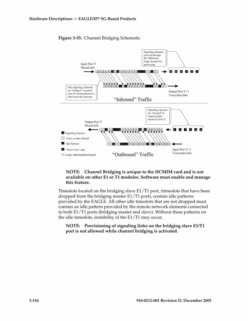
3-116 910-0212-001 Revision D, December 2005
Hardware Descriptions — EAGLE/IP7 SG-Based Products
Figure 3-55. Channel Bridging Schematic
NOTE: Channel Bridging is unique to the HCMIM card and is not available on other E1 or T1 modules. Software must enable and manage this feature.
Timeslots located on the bridging slave E1/T1 port, (timeslots that have been dropped from the bridging master E1/T1 port), contain idle patterns provided by the EAGLE. All other idle timeslots that are not dropped must contain an idle pattern provided by the remote network elements connected to both E1/T1 ports (bridging master and slave). Without these patterns on the idle timeslots, instability of the E1/T1 may occur.
NOTE: Provisioning of signaling links on the bridging slave E1/T1 port is not allowed while channel bridging is activated.
24 23 22 21 20 19 18 17 16 15 14 13 12 11 10 9 8 7 6 5 4 3 2 1
24 23 22 21 20 19 I 17 I 15 14 13 12 11 10 9 I I I 5 4 I 2 1
Input Port YMixed Info
Output Port Y+1Voice/data Info
# Signaling channel
# Voice or data channel
I Idle Patterns
X “Don’t Care” data
Non-signaling channels are “bridged” to paired port for retransmission to other network elements
18 16 8 7 6 3
Signaling channels proceed through HC-MIM and Eagle System for processing.
1 2 3 4 5 6 7 8 9 10 11 12 13 14 15 16 17 18 19 20 21 22 23 24
Output Port YMixed Info
Input Port Y+1Voice/data Info
3 6 7 8 16 18
Signaling channels are “merged” to outgoing data stream on Port Y.
1 2 X 4 5 X X X 9 10 11 12 13 14 15 X 17 X 19 20 21 22 23 24
“Inbound” Traffic
“Outbound” TrafficY is any odd numbered port
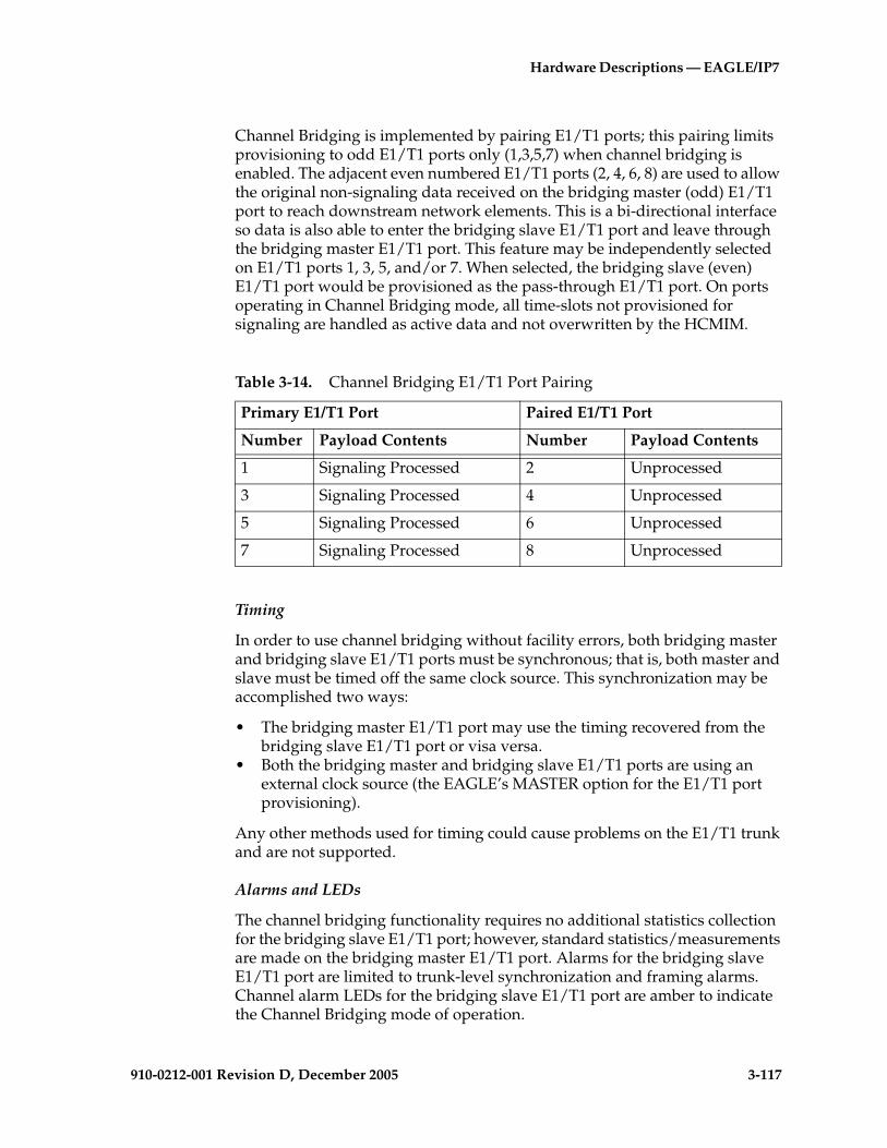
Hardware Descriptions — EAGLE/IP7
910-0212-001 Revision D, December 2005 3-117
Channel Bridging is implemented by pairing E1/T1 ports; this pairing limits provisioning to odd E1/T1 ports only (1,3,5,7) when channel bridging is enabled. The adjacent even numbered E1/T1 ports (2, 4, 6, 8) are used to allow the original non-signaling data received on the bridging master (odd) E1/T1 port to reach downstream network elements. This is a bi-directional interface so data is also able to enter the bridging slave E1/T1 port and leave through the bridging master E1/T1 port. This feature may be independently selected on E1/T1 ports 1, 3, 5, and/or 7. When selected, the bridging slave (even) E1/T1 port would be provisioned as the pass-through E1/T1 port. On ports operating in Channel Bridging mode, all time-slots not provisioned for signaling are handled as active data and not overwritten by the HCMIM.
Timing
In order to use channel bridging without facility errors, both bridging master and bridging slave E1/T1 ports must be synchronous; that is, both master and slave must be timed off the same clock source. This synchronization may be accomplished two ways:
• The bridging master E1/T1 port may use the timing recovered from the bridging slave E1/T1 port or visa versa.
• Both the bridging master and bridging slave E1/T1 ports are using an external clock source (the EAGLE’s MASTER option for the E1/T1 port provisioning).
Any other methods used for timing could cause problems on the E1/T1 trunk and are not supported.
Alarms and LEDs
The channel bridging functionality requires no additional statistics collection for the bridging slave E1/T1 port; however, standard statistics/measurements are made on the bridging master E1/T1 port. Alarms for the bridging slave E1/T1 port are limited to trunk-level synchronization and framing alarms. Channel alarm LEDs for the bridging slave E1/T1 port are amber to indicate the Channel Bridging mode of operation.
Table 3-14. Channel Bridging E1/T1 Port Pairing
Primary E1/T1 Port Paired E1/T1 Port
Number Payload Contents Number Payload Contents
1 Signaling Processed 2 Unprocessed
3 Signaling Processed 4 Unprocessed
5 Signaling Processed 6 Unprocessed
7 Signaling Processed 8 Unprocessed
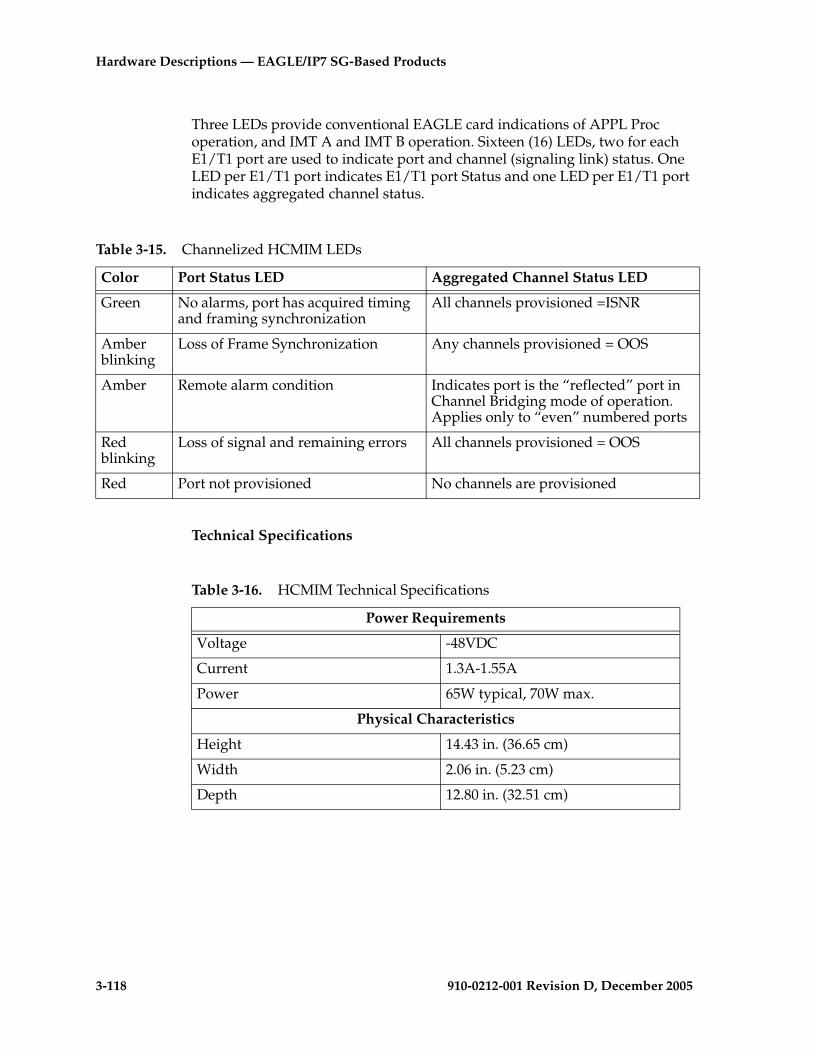
3-118 910-0212-001 Revision D, December 2005
Hardware Descriptions — EAGLE/IP7 SG-Based Products
Three LEDs provide conventional EAGLE card indications of APPL Proc operation, and IMT A and IMT B operation. Sixteen (16) LEDs, two for each E1/T1 port are used to indicate port and channel (signaling link) status. One LED per E1/T1 port indicates E1/T1 port Status and one LED per E1/T1 port indicates aggregated channel status.
Technical Specifications
Table 3-15. Channelized HCMIM LEDs
Color Port Status LED Aggregated Channel Status LED
Green No alarms, port has acquired timing and framing synchronization
All channels provisioned =ISNR
Amber blinking
Loss of Frame Synchronization Any channels provisioned = OOS
Amber Remote alarm condition Indicates port is the “reflected” port in Channel Bridging mode of operation. Applies only to “even” numbered ports
Red blinking
Loss of signal and remaining errors All channels provisioned = OOS
Red Port not provisioned No channels are provisioned
Table 3-16. HCMIM Technical Specifications
Power Requirements
Voltage -48VDC
Current 1.3A-1.55A
Power 65W typical, 70W max.
Physical Characteristics
Height 14.43 in. (36.65 cm)
Width 2.06 in. (5.23 cm)
Depth 12.80 in. (32.51 cm)

Hardware Descriptions — EAGLE/IP7
910-0212-001 Revision D, December 2005 3-119
HCMIM Cable
The cable designed for the HCMIM card is the T1 MIM LIM P/N 830-0948-XX. When upgrading from a E1/T1 MIM to an HCMIM, a cable adapter is not required. However, if you are replacing a MPL with an HCMIM, a port adapter is required.
NOTE: There will be a 830-0948-XX cable terminated on the odd shelves A and B backplane interfaces. Each cable provides four E1/T1 ports.
Air Management Card
The Air Management (P/N 870-1824-01) card is an unpowered filler card used to ensure efficient air flow in shelves equipped with fans. Air Management cards are required in all empty slots in the shelf above the 890-0001-01 fan assembly used with HCMIM cards.
Figure 3-56. Air Management card

3-120 910-0212-001 Revision D, December 2005
Hardware Descriptions — EAGLE/IP7 SG-Based Products
Fan TrayThe EAGLE fan tray 890-0001-01 contains three -48V fans that provide a redundant airflow for thermal management of the shelf. The EAGLE fan tray is powered by –48 VDC, at a fused rating of 3A. It has redundant power inputs (A and B). Each input is provided by a DB-9, keyed, positive locking connector. The contacts have 30 micro-inches of gold plating.
NOTE: Shelves with HCMIM cards are required to be cooled by fan tray 890-0001-01.
Figure 3-57. Fan Tray
Failover is governed by a fan controller card on the fan tray. The fan tray will provide adequate airflow if there is a single fan failure or during replacement of one of the three fans while the EAGLE fan tray is operational. The control card bracket provides mounting for the control PCB (P/N 850-0703-01). The control PCB inserts into the front face of the fan tray on card guides mounted to the left side wall, and is intended to be a field replaceable item.
The EAGLE fan tray is designed to be field installable, with mounting brackets, in both a Tekelec Heavy Duty frame and a standard frame. There is one disposable air filter in the assembly (P/N 551-0032-01). The filters should be changed once a month.
The EAGLE fan tray is designed to be compliant to Bellcore Standards GR-63-CORE [4], GR-78-CORE [5], and GR-1089-CORE [6] when mounted in a Tekelec Heavy Duty Frame or standard frame. The EAGLE fan tray is also designed to be UL and CE compliant. The EAGLE fan tray is designed to operate in a Central Office environment with continuous operation at -5C to 50C and 5% to 90% RH in compliance with GR-63-CORE.
Fan Filter
Filter Tab
Fan Card
Replaceable Fans

Hardware Descriptions — EAGLE/IP7
910-0212-001 Revision D, December 2005 3-121
Fuse and Alarm Panels
This section describes the Fuse and Alarm Panels (FAPs).
The FAP (P/N 870-2320-xx or P/N 870-1606-xx) are used in Tekelec frames. FAP 870-2320-01 Rev A through I handles 40 Amp feeds; FAP 870-2320-01 Rev J handles 60 Amp feeds. 870-1606-xx is identical to the 870-2320-xx except that it is installed into standard frames. 870-1606-02 Rev A through B handles 40 Amp feeds, and 870-1606-02 Rev C handles 60 Amp feeds.
NOTE: Beginning with EAGLE software release 33.0, all frames containing HCMIM modules are required to have 60 Amp power circuits and the FAP must be upgraded to accommodate 60 Amp feeds. The FAPs required are: P/N 870-2320-01 Rev J (with diode kit P/N 870-1831-02) for heavy-duty frames or 60 Amp FAP P/N 870-1606-02 Rev C (with diode kit 870-1831-01) for standard frames. FAP 870-1606-01 cannot be upgraded to 60 Amps and must be replaced if 60 Amp feeds are required. Customers do not perform FAP upgrade; these upgrades are performed by Tekelec personnel.
NOTE: To allow for the full population of an EAGLE 5 SAS frame, and for the failure of one primary supply, the circuit breakers for each frame should be rated at 40 Amperes (all new installs beginning with EAGLE 5 SAS Release 34.0 will require two 60 Ampere feeds).
The FAP provides protected distribution of power to the system. Protection is provided by fuses placed in fuse holders on the front panel. The FAP contains a fuse fail alarm circuit that operates when one or more fuses fail. A Light Emitting Diode (LED) changes from green to red when a fuse fails. The LED remains red until the failed fuse is replaced with a new fuse. When the failed fuse is removed the alarm stops.
The fuse and alarm panel are protected by two or four Plexiglas covers. These covers are used primarily to protect the connectors and wiring from damage, and to protect craft personnel from the live current on the back panel.
The fuse and alarm panel uses the correct fuses for individual circuit protection (refer to Figure 3-62 "Fuse (GMT Brand Shown)" on page 3-126). The system uses one amp, two amp, three amp, 7.5 amp, and ten amp fuses, depending on the application. When a fuse fails due to an overload condition, a small colored flag on the fuse shows the position of the fuse that has failed. The flag is gray on a one amp fuse, blue on a three amp fuse, black/white on 7.5 amp fuses, and red/white on a ten amp fuse.
The panel contains two separate circuits, A and B. Current flows from the input terminals to the fuse bus. When a fuse is installed in a fuse holder, the circuit is completed to the output connector. The fuse alarm LED on the front panel indicates the condition of the panel. Green is indicated if power is applied to the panel and there are no failed fuses. The green LED changes to red when a fuse fails. An unlit LED indicates a failed LED or no power to the fuse and alarm panel.

3-122 910-0212-001 Revision D, December 2005
Hardware Descriptions — EAGLE/IP7 SG-Based Products
The fuse and alarm panel is also equipped with frame status alarm LEDs that display the critical, major, and minor alarms generated by the system.
The fuse and alarm panel has the A and B buses connected through diodes to allow one bus to pick up the entire load when the other bus loses power.
New installations of Control and Extension Frames (as of Release 34.0) use 60 amp breakers (see note), the EOAP Frames use 30 amp breakers, the ELAP frames use 30 amp and 60 amp breakers, and the EPAP frames use 30 amp breakers. Local Alarms for the Frame’s Power Distribution System are provided at each frame.
NOTE: Existing frames that are fused at 40 amps can be upgraded to support 60 amps with a FAP upgrade kit. 60 amps is required for frames that contain HC-MIMs.
CAUTION: All personnel associated with the installation of this system must adhere to all safety precautions and protection equipment required to avoid the possibility of injury to personnel, service degradation, and/or service interruption. This is a redundant system to allow service during normal maintenance. When repairs require a total power disconnect both input supply sources must be disconnected. This will cause service interruption and take down the system.
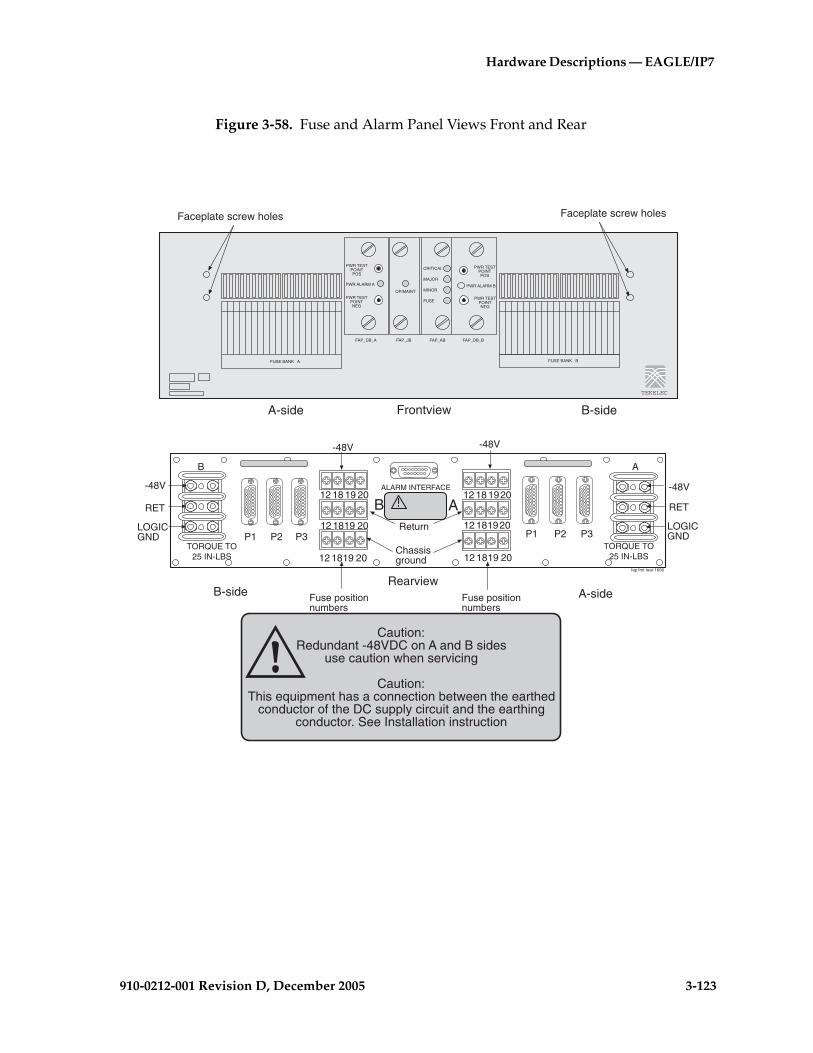
Hardware Descriptions — EAGLE/IP7
910-0212-001 Revision D, December 2005 3-123
Figure 3-58. Fuse and Alarm Panel Views Front and Rear
TEKELEC
PWR TESTPOINTPOS
PWR ALARM A
PWR TESTPOINTNEG
OP/MAINT
CRITICAL
MAJOR
MINOR
FUSE
PWR TESTPOINTPOS
PWR ALARM B
PWR TESTPOINTNEG
FAP_DB_A FAP_JB FAP_AB FAP_DB_B
FUSE BANK A FUSE BANK B
B-sideA-side Frontview
fap frnt rear 1606
B-side A-sideRearview
AB
P1 P2 P3 P1 P2 P3
12 18 19 20
12 1819 20
12 18 1920
12 181920
-48V
RET
LOGICGND
B A
-48V
RET
LOGICGND
ALARM INTERFACE
-48V
Return
Chassisground
-48V
Fuse positionnumbers
Fuse positionnumbers
12 1819 20 12 1819 20TORQUE TO
25 IN-LBSTORQUE TO
25 IN-LBS
Faceplate screw holesFaceplate screw holes
Caution:Redundant -48VDC on A and B sides
use caution when servicing
Caution:This equipment has a connection between the earthed
conductor of the DC supply circuit and the earthingconductor. See Installation instruction
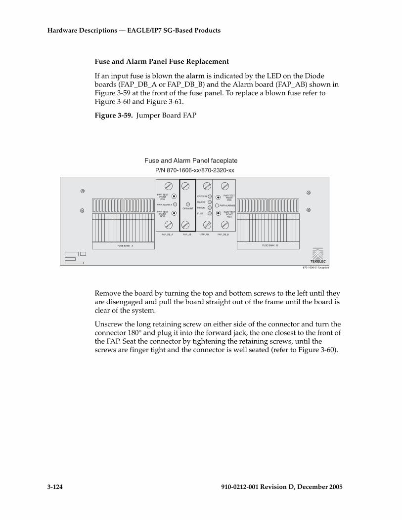
3-124 910-0212-001 Revision D, December 2005
Hardware Descriptions — EAGLE/IP7 SG-Based Products
Fuse and Alarm Panel Fuse Replacement
If an input fuse is blown the alarm is indicated by the LED on the Diode boards (FAP_DB_A or FAP_DB_B) and the Alarm board (FAP_AB) shown in Figure 3-59 at the front of the fuse panel. To replace a blown fuse refer to Figure 3-60 and Figure 3-61.
Figure 3-59. Jumper Board FAP
Remove the board by turning the top and bottom screws to the left until they are disengaged and pull the board straight out of the frame until the board is clear of the system.
Unscrew the long retaining screw on either side of the connector and turn the connector 180° and plug it into the forward jack, the one closest to the front of the FAP. Seat the connector by tightening the retaining screws, until the screws are finger tight and the connector is well seated (refer to Figure 3-60).
PWR TESTPOINTPOS
PWR ALARM A
PWR TESTPOINTNEG
OP/MAINT
CRITICAL
MAJOR
MINOR
FUSE
PWR TESTPOINTPOS
PWR ALARM B
PWR TESTPOINTNEG
FAP_DB_A FAP_JB FAP_AB FAP_DB_B
FUSE BANK A FUSE BANK B
TEKELEC
P/N 870-1606-xx/870-2320-xx
870 1606 01 faceplate
Fuse and Alarm Panel faceplate
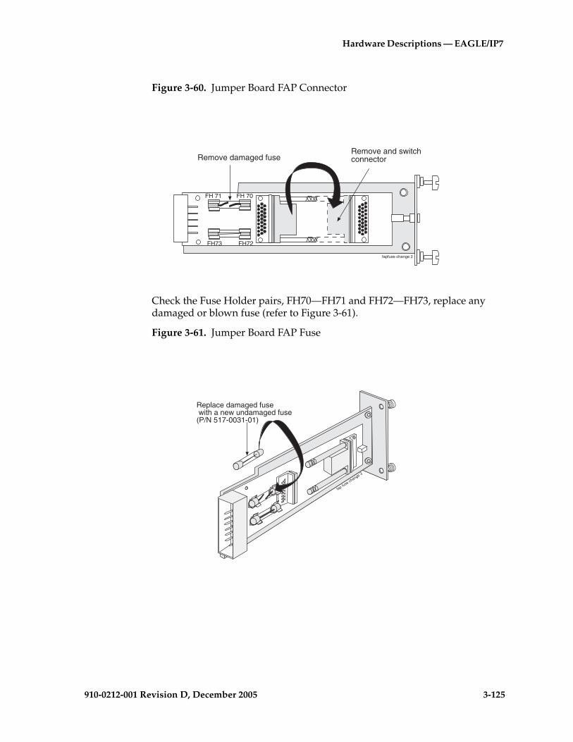
Hardware Descriptions — EAGLE/IP7
910-0212-001 Revision D, December 2005 3-125
Figure 3-60. Jumper Board FAP Connector
Check the Fuse Holder pairs, FH70—FH71 and FH72—FH73, replace any damaged or blown fuse (refer to Figure 3-61).
Figure 3-61. Jumper Board FAP Fuse
fapfuse change 2
FH 71 FH 70
FH72FH73
Remove and switchconnectorRemove damaged fuse
Replace damaged fuse with a new undamaged fuse(P/N 517-0031-01)
fap fuse change 3

3-126 910-0212-001 Revision D, December 2005
Hardware Descriptions — EAGLE/IP7 SG-Based Products
Return the board to the appropriate slot, making sure the board is well seated. Tighten the screws on the front of the jumper board on the front of the Fuse and Alarm Panel (FAP). The LED on the front of the jumper board should now be green.
Figure 3-62. Fuse (GMT Brand Shown)
Table 3-17. Fuse and Alarm Panel Front Items, OP/MAINT (P/N 870-1606-xx/870-2320-xx)
Fuse Panel Item Description
Fuse Positions Two groups of 20 GMT fuses
OP/MAINT Alarm (On FAP_JB) LED indicator for fuse fail alarm
Fuse Alarm (On FAP_AB) LED indicator for fuse fail alarm
Critical Alarm (On FAP_AB) LED indicator for critical alarm
Major Alarm (On FAP_AB) LED indicator for major alarm
Minor Alarm (On FAP_AB) LED indicator for minor alarm
Power Alarm (On FAP_DB_A or FAP_DB_B)
LED indicator for loss of power on either A bus or B bus
Blown positionFlag
Ready position
Fuse flag colorsgray - 1Ablue - 3Ablack / white - 7.5Ared / white - 10A
gmt fuse
Blown positionFlag
Ready position
Blown position
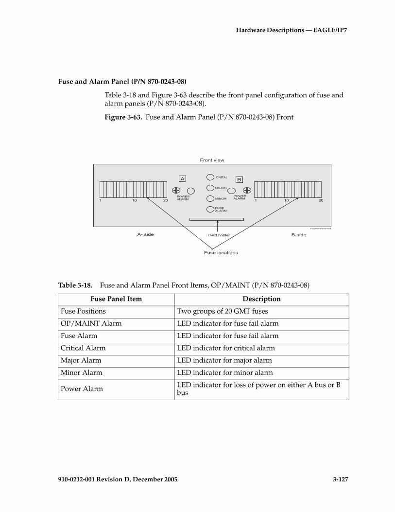
Hardware Descriptions — EAGLE/IP7
910-0212-001 Revision D, December 2005 3-127
Fuse and Alarm Panel (P/N 870-0243-08)
Table 3-18 and Figure 3-63 describe the front panel configuration of fuse and alarm panels (P/N 870-0243-08).
Figure 3-63. Fuse and Alarm Panel (P/N 870-0243-08) Front
A B+,�-.�
�.��,
����,
�/��.�.,�
��0�,.�.,�
��0�,.�.,�
+�$ ��"' �$
� �� �� � �� ��
FuseAlarmPanel-front
.1��� � �1�� �
�$"!��)��&
�#���'"����"!�
Table 3-18. Fuse and Alarm Panel Front Items, OP/MAINT (P/N 870-0243-08)
Fuse Panel Item Description
Fuse Positions Two groups of 20 GMT fuses
OP/MAINT Alarm LED indicator for fuse fail alarm
Fuse Alarm LED indicator for fuse fail alarm
Critical Alarm LED indicator for critical alarm
Major Alarm LED indicator for major alarm
Minor Alarm LED indicator for minor alarm
Power Alarm LED indicator for loss of power on either A bus or B bus
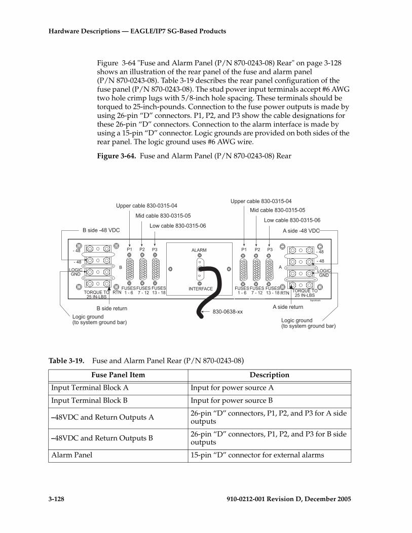
3-128 910-0212-001 Revision D, December 2005
Hardware Descriptions — EAGLE/IP7 SG-Based Products
Figure 3-64 "Fuse and Alarm Panel (P/N 870-0243-08) Rear" on page 3-128 shows an illustration of the rear panel of the fuse and alarm panel (P/N 870-0243-08). Table 3-19 describes the rear panel configuration of the fuse panel (P/N 870-0243-08). The stud power input terminals accept #6 AWG two hole crimp lugs with 5/8-inch hole spacing. These terminals should be torqued to 25-inch-pounds. Connection to the fuse power outputs is made by using 26-pin “D” connectors. P1, P2, and P3 show the cable designations for these 26-pin “D” connectors. Connection to the alarm interface is made by using a 15-pin “D” connector. Logic grounds are provided on both sides of the rear panel. The logic ground uses #6 AWG wire.
Figure 3-64. Fuse and Alarm Panel (P/N 870-0243-08) Rear
,��%������)
-.�/01 �/
" 0 ���
���
"23-�3.4
0�.
�� �� ��
1'�/����
1'�/�����
1'�/������
!
�� �� ��
1'�/����
1'�/�����
1'�/������ 0�.
"23-�3.4
���
���
�205'/�2��-.�"!�
�205'/�2��-.�"!�
!)�6����74�
'����%�$�������������
�6%�$�������������
"�#%�$������������� )�6����74�
!)�6������� )�6�������
"�8�%8����69��)()��*8����6$��: "�8�%8����6
9��)()��*8����6$��:
'����%�$�������������
�6%�$�������������
"�#%�$�������������
���������++
Table 3-19. Fuse and Alarm Panel Rear (P/N 870-0243-08)
Fuse Panel Item Description
Input Terminal Block A Input for power source A
Input Terminal Block B Input for power source B
–48VDC and Return Outputs A 26-pin “D” connectors, P1, P2, and P3 for A side outputs
–48VDC and Return Outputs B 26-pin “D” connectors, P1, P2, and P3 for B side outputs
Alarm Panel 15-pin “D” connector for external alarms

Hardware Descriptions — EAGLE/IP7
910-0212-001 Revision D, December 2005 3-129
Fuse and Alarm Panel (P/N 870-0243-09)
This fuse and alarm panel is used by the Miscellaneous Frame (MF) and the OAP Frame (OAPF).
Table 3-21 and Figure 3-65 describe the front panel configuration of fuse and alarm panel (P/N 870-0243-09).
Table 3-20. Fuse and Alarm Panel Specifications (P/N 870-0243-08)
Power Requirements
Voltage –48VDC
Current Capacity 40 amp “A” or “B”
Power Dissipation 8 W, no fuse load
Capacities
Fuse Positions 40 GMT Fuses in 2 Groups of 20
Current Capacity 40 amp “A” or “B”
Dimensions
HeightWidthDepth
3 in. (7.6 cm)17 in. (43.2 cm)10.25 in. (26 cm)
Table 3-21. Fuse and Alarm Panel (P/N 870-0243-09) Front Items
Fuse Panel Item Description
Fuse Positions Two groups of 20 GMT fuses
Card Holder Slide-card holder with two designation cards for 20 fuse positions each
Fuse Alarm LED indicator for fuse fail alarm
Critical Alarm LED indicator for critical alarm
Major Alarm LED indicator for major alarm
Minor Alarm LED indicator for minor alarm
Power Alarm LED indicator for loss of power on either A bus or B bus

3-130 910-0212-001 Revision D, December 2005
Hardware Descriptions — EAGLE/IP7 SG-Based Products
Figure 3-65. Fuse and Alarm Panel (P/N 870-0243-09) Front
Figure 3-66 "Fuse and Alarm Panel (P/N 870-0243-09) Rear" on page 3-130 shows a diagram of the rear panel of the fuse and alarm panel (P/N 870-0243-09). Table 3-22 describes the rear panel configuration of the fuse and alarm panel (P/N 870-0243-09). The stud power input terminals accept #6 AWG two hole crimped lugs with 5/8-inch hole spacing. These terminals should be torqued to 25-inch-pounds. Connection to the fuse power outputs is made by using 26-pin “D” connectors. Logic grounds are provided on both sides of the rear panel. The logic ground uses #6 AWG wire.
Figure 3-66. Fuse and Alarm Panel (P/N 870-0243-09) Rear
A B+,�-.�
�.��,
����,
�/��.�.,�
��0�,.�.,�
��0�,.�.,�
+�$ ��"' �$
� �� �� � �� ��
FuseAlarmPanel-front
.1��� � �1�� �
�$"!��)��&
�#���'"����"!�
Holdover clock rearview
INTERFACE
ALARM
- 48
- 48LOGICGND
RTN
B A
TORQUE TO25 IN-LBSTORQUE TO 25
IN-LBSCHASISGND
RTN
-48VDC -48VDC
RTN
CHASISGND
- 48
- 48
LOGICGND
RTN
Input Terminal Block B Input Terminal Block A
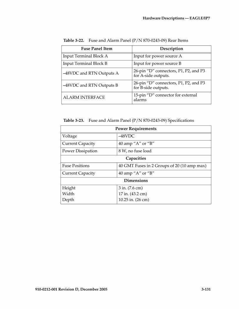
Hardware Descriptions — EAGLE/IP7
910-0212-001 Revision D, December 2005 3-131
Table 3-22. Fuse and Alarm Panel (P/N 870-0243-09) Rear Items
Fuse Panel Item Description
Input Terminal Block A Input for power source A
Input Terminal Block B Input for power source B
–48VDC and RTN Outputs A 26-pin “D” connectors, P1, P2, and P3 for A-side outputs.
–48VDC and RTN Outputs B 26-pin “D” connectors, P1, P2, and P3 for B-side outputs.
ALARM INTERFACE 15-pin “D” connector for external alarms
Table 3-23. Fuse and Alarm Panel (P/N 870-0243-09) Specifications
Power Requirements
Voltage –48VDC
Current Capacity 40 amp “A” or “B”
Power Dissipation 8 W, no fuse load
Capacities
Fuse Positions 40 GMT Fuses in 2 Groups of 20 (10 amp max)
Current Capacity 40 amp “A” or “B”
Dimensions
HeightWidthDepth
3 in. (7.6 cm)17 in. (43.2 cm)10.25 in. (26 cm)
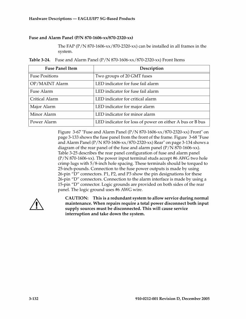
3-132 910-0212-001 Revision D, December 2005
Hardware Descriptions — EAGLE/IP7 SG-Based Products
Fuse and Alarm Panel (P/N 870-1606-xx/870-2320-xx)
The FAP (P/N 870-1606-xx/870-2320-xx) can be installed in all frames in the system.
Figure 3-67 "Fuse and Alarm Panel (P/N 870-1606-xx/870-2320-xx) Front" on page 3-133 shows the fuse panel from the front of the frame. Figure 3-68 "Fuse and Alarm Panel (P/N 870-1606-xx/870-2320-xx) Rear" on page 3-134 shows a diagram of the rear panel of the fuse and alarm panel (P/N 870-1606-xx). Table 3-25 describes the rear panel configuration of fuse and alarm panel (P/N 870-1606-xx). The power input terminal studs accept #6 AWG two hole crimp lugs with 5/8-inch hole spacing. These terminals should be torqued to 25-inch-pounds. Connection to the fuse power outputs is made by using 26-pin “D” connectors. P1, P2, and P3 show the pin designations for these 26-pin “D” connectors. Connection to the alarm interface is made by using a 15-pin “D” connector. Logic grounds are provided on both sides of the rear panel. The logic ground uses #6 AWG wire.
CAUTION: This is a redundant system to allow service during normal maintenance. When repairs require a total power disconnect both input supply sources must be disconnected. This will cause service interruption and take down the system.
Table 3-24. Fuse and Alarm Panel (P/N 870-1606-xx/870-2320-xx) Front Items
Fuse Panel Item Description
Fuse Positions Two groups of 20 GMT fuses
OP/MAINT Alarm LED indicator for fuse fail alarm
Fuse Alarm LED indicator for fuse fail alarm
Critical Alarm LED indicator for critical alarm
Major Alarm LED indicator for major alarm
Minor Alarm LED indicator for minor alarm
Power Alarm LED indicator for loss of power on either A bus or B bus

Hardware Descriptions — EAGLE/IP7
910-0212-001 Revision D, December 2005 3-133
Figure 3-67. Fuse and Alarm Panel (P/N 870-1606-xx/870-2320-xx) Front
fap frnt
TEKELEC
PWR TESTPOINTPOS
PWR ALARM A
PWR TESTPOINTNEG
OP/MAINT
CRITICAL
MAJOR
MINOR
FUSE
PWR TESTPOINTPOS
PWR ALARM B
PWR TESTPOINTNEG
FAP_DB_A FAP_JB FAP_AB FAP_DB_B
FUSE BANK A FUSE BANK B
B-sideA-side Frontview
Faceplate Screw holes
Fuse location labels Fuse location labelsPart numberBar codeSerialization number
Faceplate Screw holes
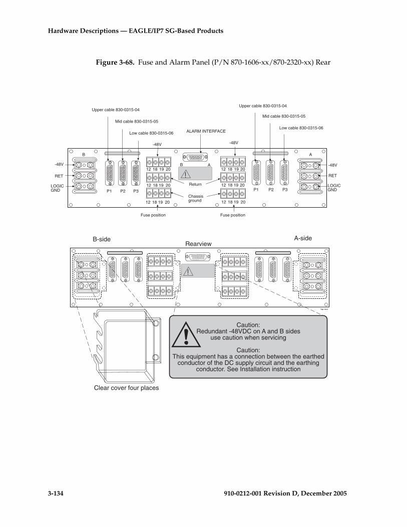
3-134 910-0212-001 Revision D, December 2005
Hardware Descriptions — EAGLE/IP7 SG-Based Products
Figure 3-68. Fuse and Alarm Panel (P/N 870-1606-xx/870-2320-xx) Rear
B-side A-sideRearview
Clear cover four places
fap-rear
Upper cable 830-0315-04
Mid cable 830-0315-05
Low cable 830-0315-06
Upper cable 830-0315-04
Mid cable 830-0315-05
Low cable 830-0315-06
AB
P1 P2 P3 P1 P2 P3
12 18 19 20
12 18 19 20
12 18 19 20
12 18 19 20
-48V
RET
LOGICGND
B A
-48V
RET
LOGICGND
ALARM INTERFACE
-48V
Return
Chassisground
-48V
Fuse position Fuse position
12 18 19 20 12 18 19 20
Caution:Redundant -48VDC on A and B sides
use caution when servicing
Caution:This equipment has a connection between the earthed
conductor of the DC supply circuit and the earthingconductor. See Installation instruction

Hardware Descriptions — EAGLE/IP7
910-0212-001 Revision D, December 2005 3-135
Table 3-25. Fuse and Alarm Panel (P/N 870-1606-xx/870-2320-xx) Rear
Fuse Panel Item Description
Input Terminal Block A Input for power source A
Input Terminal Block B Input for power source B
Output Terminal Block A Fuse location 12, 18, 19, and 20 for side A. Refer to Provision Rules
Output Terminal Block B Fuse location 12, 18, 19, and 20 for side B. Refer to Provision Rules
–48VDC and Return Outputs, Chassis Gnd
Fuse position 12, 18, 19, and 20
Miscellaneous extra capacity fuses refer to the section on Provision Rules for FAP (P/N 870-1606-xx/870-2320-xx) Fuse Locations3–136
–48VDC and Return Outputs A 26-pin “D” connectors, P1, P2, and P3 for A-side outputs.
–48VDC and Return Outputs B 26-pin “D” connectors, P1, P2, and P3 for B-side outputs.
Alarm Panel 15-pin “D” connector for external alarms
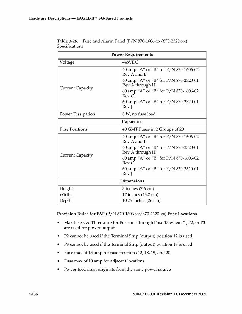
3-136 910-0212-001 Revision D, December 2005
Hardware Descriptions — EAGLE/IP7 SG-Based Products
Provision Rules for FAP (P/N 870-1606-xx/870-2320-xx) Fuse Locations
• Max fuse size Three amp for Fuse one through Fuse 18 when P1, P2, or P3 are used for power output
• P2 cannot be used if the Terminal Strip (output) position 12 is used
• P3 cannot be used if the Terminal Strip (output) position 18 is used
• Fuse max of 15 amp for fuse positions 12, 18, 19, and 20
• Fuse max of 10 amp for adjacent locations
• Power feed must originate from the same power source
Table 3-26. Fuse and Alarm Panel (P/N 870-1606-xx/870-2320-xx) Specifications
Power Requirements
Voltage –48VDC
Current Capacity
40 amp “A” or “B” for P/N 870-1606-02 Rev A and B40 amp “A” or “B” for P/N 870-2320-01 Rev A through H60 amp “A” or “B” for P/N 870-1606-02 Rev C60 amp “A” or “B” for P/N 870-2320-01 Rev J
Power Dissipation 8 W, no fuse load
Capacities
Fuse Positions 40 GMT Fuses in 2 Groups of 20
Current Capacity
40 amp “A” or “B” for P/N 870-1606-02 Rev A and B40 amp “A” or “B” for P/N 870-2320-01 Rev A through H60 amp “A” or “B” for P/N 870-1606-02 Rev C60 amp “A” or “B” for P/N 870-2320-01 Rev J
Dimensions
HeightWidthDepth
3 inches (7.6 cm)17 inches (43.2 cm)10.25 inches (26 cm)

Hardware Descriptions — EAGLE/IP7
910-0212-001 Revision D, December 2005 3-137
• Fuse and Alarm Panel, Jumper Board (P/N 870-1641-01) fuse size on boards 40 amp per side for P/N 870-1606-02 Rev A and B, and for P/N 870-2320-01 Rev A through I. Fuse size on boards 60 amp per side for P/N 870-1606-02 Rev C and 870-2320-01 Rev J.
• Fuse and Alarm Panel, Jumper board in maintenance mode must be less than 40 amp per distributed output side.
Label Kit for Fuse and Alarm Panel (P/N 870-1606-xx/870-2320-xx)
Label Kit (P/N 870-1915-01) contains large sheets of die-cut stick-on labels for the appropriate frames. There are three large sheets of die-cut, stick-on labels:
• Sheet (P/N 658-0604-01) is for FUSE BANK A, CONTROL FRAME through EF-04
• Sheet (P/N 658-0604-02) is for FUSE BANK B, CONTROL FRAME through EF-04
• Sheet (P/N 658-0604-03) is for MISC FRAME
Also included in the Label Kit (P/N 870-1915-01) are smaller die-cut stick-on labels for different fuses relating to different amps and individual pieces of site-specific equipment; these are to be pressed into fuse OPEN spaces.
Procedure – Faceplate Labels
1. Peel the individual die-cut label that designates a specific frame from one of the three large die-cut sheets of labels.
2. Press the sticky side of the label into the silk screened area on the front of the faceplate of the Fuse and Alarm Panel (P/N 870-1606-xx) for the specific frame (refer to Figure 3-69 "FAP, Fuse Label Kit (P/N 870-1915-01)" on page 3-138). The left side of the faceplate is marked A and the right side of the faceplate is marked B.
3. The label designates CONTROL FRAME or EF-00 through EF-04. There are also labels for the MISC FRAME.
The labels must be pressed into place on the front faceplate of the correct frame.
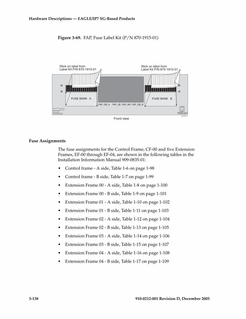
3-138 910-0212-001 Revision D, December 2005
Hardware Descriptions — EAGLE/IP7 SG-Based Products
Figure 3-69. FAP, Fuse Label Kit (P/N 870-1915-01)
Fuse Assignments
The fuse assignments for the Control Frame, CF-00 and five Extension Frames, EF-00 through EF-04, are shown in the following tables in the Installation Information Manual 909-0835-01:
• Control frame - A side, Table 1-6 on page 1-98
• Control frame - B side, Table 1-7 on page 1-99
• Extension Frame 00 - A side, Table 1-8 on page 1-100
• Extension Frame 00 - B side, Table 1-9 on page 1-101
• Extension Frame 01 - A side, Table 1-10 on page 1-102
• Extension Frame 01 - B side, Table 1-11 on page 1-103
• Extension Frame 02 - A side, Table 1-12 on page 1-104
• Extension Frame 02 - B side, Table 1-13 on page 1-105
• Extension Frame 03 - A side, Table 1-14 on page 1-106
• Extension Frame 03 - B side, Table 1-15 on page 1-107
• Extension Frame 04 - A side, Table 1-16 on page 1-108
• Extension Frame 04 - B side, Table 1-17 on page 1-109
fap-lable frnt
FUSE BANK A FUSE BANK B
Front view
TEKELEC
FAP_DB_A FAP_JB FAP_AB FAP_DB_B
Stick on label fromLabel Kit P/N 870-1915-01
Stick on label fromLabel Kit P/N 870-1915-01
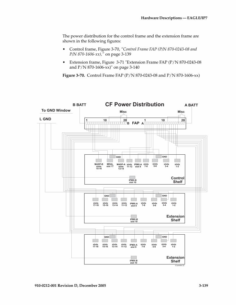
Hardware Descriptions — EAGLE/IP7
910-0212-001 Revision D, December 2005 3-139
The power distribution for the control frame and the extension frame are shown in the following figures:
• Control frame, Figure 3-70, “Control Frame FAP (P/N 870-0243-08 and P/N 870-1606-xx),” on page 3-139
• Extension frame, Figure 3-71 "Extension Frame FAP (P/N 870-0243-08 and P/N 870-1606-xx)" on page 3-140
Figure 3-70. Control Frame FAP (P/N 870-0243-08 and P/N 870-1606-xx)
1�� �� ��� ��
� ��� �� �������/��23���4
���/�
�����5�6�57
1���4����3��389�3��
����
�/�
������5�������
5�����
5�����
������5����
����5�����
����� 5�����
�/�
�:���3���6�57
�/� �/�
�:���3���6�57
�/� �/�
����� 5�������
5�����
5�����
5�����
5�������
5�������
5�������
5�������
5�����
5�����
5�����
������5����
����� 5�����
5�����
5�������
5�������
5�������
5�������
5�����
5�����
5�����
������5����
����� 5�����
5�������
%,��#6�)���
�3�3
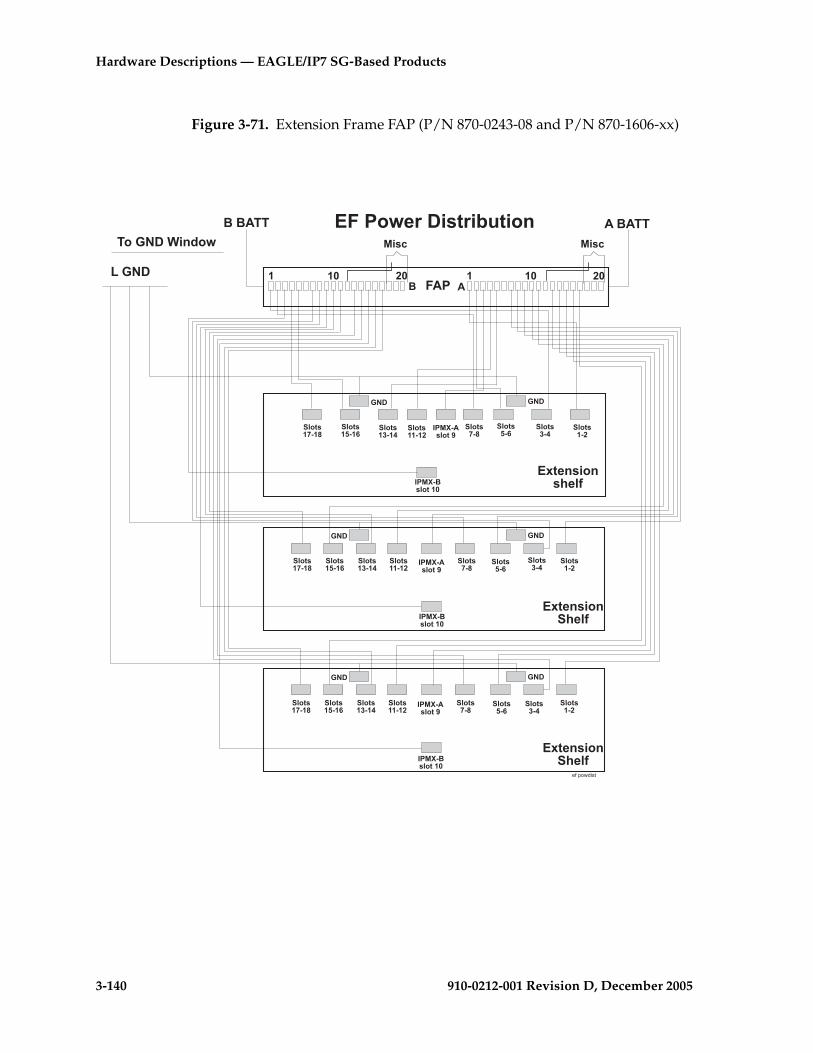
3-140 910-0212-001 Revision D, December 2005
Hardware Descriptions — EAGLE/IP7 SG-Based Products
Figure 3-71. Extension Frame FAP (P/N 870-0243-08 and P/N 870-1606-xx)
1�� �� ��� ��
� ��� �� �������/��23���4
���/�
�:���3��6�57
�1���4����3��389�3��
����
�/�
�5�������
�5�����
�5�����
������5����
�5�������
����� 5�����
�/�
�:���3���6�57
�/� �/�
�:���3���6�57
�/� �/�
�5�������
�5�����
�5�����
�5�����
�5�������
�5�������
�5�������
�5�������
�5�����
�5�����
�5�����
������5����
����� 5�����
�5�����
�5�������
�5�������
�5�������
�5�������
�5�����
�5�����
�5�����
������5����
����� 5�����
�5�������
�,��#6�)�
�3�3

Hardware Descriptions — EAGLE/IP7
910-0212-001 Revision D, December 2005 3-141
Holdover Clock
The holdover clock (refer to Figure 3-72 "Holdover Clock" on page 3-142) is an optional device that can maintain clock synchronization for system Digital Signal Level-0 Applique (DS0A) links during brief (up to 15 seconds) Building Integrated Timing System (BITS) clock signal outages. This follows Telcordia Technology requirements as specified in GR-1244-CORE.
The holdover clock is connected to the BITS clock source in the system. The BITS clock inputs to the system through the control shelf. The device is located in, and receives –48VDC power from, a miscellaneous frame (refer to Figure 3-73 "Holdover Clock" on page 3-143).
Connections from the holdover clock to the system control shelf consist of two clock cables and a cable to signal holdover clock alarm conditions to other parts of the system.
The holdover clock contains the following:
• Maintenance Interface System (MIS) (P/N 804-0175-01) card system alarm interface which provides alarms output to the system control shelf.
• Two Critical Status Indicators (CI) (P/N 804-0165-01) cards for clock inputs A and B.
• Two Signal Transfer, Stratum-3 (ST-3) (P/N 804-0173-01) cards for clocks A and B.
• Three Timing Output Composite Clock Automatic (TOCA) (P/N 804-0166-01) cards, clock outputs (TO1 and TO2) for A and B through the system control shelf.
NOTE: The TOCA cards my be replaced with TOLA cards. For wiring information on TOLA cards see the Installation Manual.
• One Matrix Controller Automatic-5 (MCA)(P/N 804-0251-01) card controls the output protection switch matrix just above the Data Carrier Detect (DCD) DCD-523 shelf card slots.
The outputs of the TOCA cards are connected to a wire-wrap panel mounted on top of the holdover clock. The clock inputs on the system’s control shelf are connected to the holdover clock wire-wrap panel.

3-142 910-0212-001 Revision D, December 2005
Hardware Descriptions — EAGLE/IP7 SG-Based Products
Figure 3-72. Holdover Clock
OUTPUT SPARE
TO2 TO3 TO4 TO5 TO10 HS1TO1DIGITAL CLOCK DISTRIBUTORDCD–523
-48V A5A
-48V B5A
TO7 TO8 TO9TO6
CI
HS2
hocklrnt.eps
CI cards
MIS card
MCA card
TOCA cardsST3 cards Hot sparesTOCA cardpositions
TOCAST3 ST3 TOCA MISCI MCA-5TOCA TOCABLANK BLANK
OptionalTOCA cards

Hardware Descriptions — EAGLE/IP7
910-0212-001 Revision D, December 2005 3-143
Figure 3-73. Holdover Clock
Maintenance Interface System Card
The Maintenance Interface System (MIS)(P/N 804-0175-01) card provides local and remote command and control for the holdover clock. The MIS card is installed in the far right slot of the holdover clock shelf (refer to Figure 3-74 "Maintenance Interface System Card Block Diagram" on page 3-144 for an MIS card block diagram).
The MIS provides Data Carrier Detect (DCD) alarm summary with office and remote alarm relay closures and status indicators, as well as remote RS-232 communication.
Output alarms from the Timing Output Composite Clock Automatic (TOCA) cards, input reference alarms from the clock inputs, and failure alarms from any card in the shelf are sent to the MIS card. Status indications including clock loss and port alarms are also monitored by the MIS card.
MF-00
Holdover clock
BITS clocksource
CF-00
Control shelfHoldover clock alarms
Primary and secondaryBITS clocks
holdover sysblk.eps

3-144 910-0212-001 Revision D, December 2005
Hardware Descriptions — EAGLE/IP7 SG-Based Products
Depending on which alarms are received, the MIS activates audible and visual alarm and Status Indicator (SI) outputs. An additional set of status leads on the back enables either a major, minor, or critical alarm in the event of the failure of a battery or blown fuse.
NOTE: Major, minor, and critical alarm leads have both Normally Open (NO) and Normally Closed (NC) dry relay contacts. Major, minor, and critical status indicators have NO relay contacts only. All other Status Indicators are open-collector outputs between the SI lead and battery return.
Alarm battery supply is not required for the system. When DC power is lost to the shelf, the normally open relays close, initiating an office alarm (refer to Figure 3-74).
Figure 3-74. Maintenance Interface System Card Block Diagram
A front-panel Alarm Cut Off (ACO) push button, when pressed, silences the audible alarm and lights the ACO lamp. The ACO push buttons on all shelves in the system have the same effect. An external lead on the shelf backplane is provided for remote ACO operation.
The status of the shelf is available at the front panel lamps. A Major, Minor, or Critical lamp lights to indicate that one of those alarms exists on the shelf. The Fail lamp lights to indicate the MIS card has failed. The Alarm Cut Off (ACO) lamp lights when the ACO push button, is pressed to silence an audible alarm, before the alarm is cleared.
�2;/0 .41'�/
-�02�02�/��20
0������20��
0������20��
/� .�-2.�2 �20�
102
'4-!"/ 9.2<.�:7-�' " 9.2<.�:
�� �'� -.4-� �20�
102
�20 �0-�-� "
�2 -.20
�2�;-��=
�=/"1� 04�
" 0 � 04-. /� .�-2.
�=/"10������20��
2.-�20
�0-�-� " 9.2<.�:
" 0 "23-� .4
�- /0�/7/.�"23
"2� "�2
*�)$��%&

Hardware Descriptions — EAGLE/IP7
910-0212-001 Revision D, December 2005 3-145
Critical Status Indicators Card
Two Card Indicator (CI)(P/N 804-0165-01) cards, provide input signal redundancy. Each CI card uses one Common Channel (CC) or one Digital Signal Level 1 (DS1) input as its timing reference. A switch on the CI card selects the type of input and the framing format, if DS1, of the input timing signal. Front panel lamps (CC and DS1) show which type of input is present.
Under normal operating conditions, CI A drives clock card A, and CI B drives clock card B. Both input reference signals are simultaneously monitored, and if an input fails, the clock card automatically switches to the other CI card, which then supplies both clock cards until the failed reference is restored. The SOURCE ACTIVE lamp on the front panel indicates which CI card is on-line.
The CI card contains a source control circuit that causes the card to switch to the redundant CI card if the primary card, defined as the card currently in operation, fails.
Transfer between CI cards can be manually initiated by pressing the front-panel XFR switch on either CI card.
Switching activity between CI A and CI B will not cause the timing outputs to transmit phase hits, as the phase information of the active signal is transferred to the redundant CI card before switching. A Phase Locked Crystal Oscillator (PLXO) keeps the CI output stable while the transfer takes place. The PLXO also removes any phase jitter from the incoming signal before it passes the reference to the Timing Output Composite Clock Automatic (TOCA) cards.
If both CI cards fail, the clock cards go into holdover mode, and the system automatically uses the active clock card.
Stratum-3 Card
The Signal Transfer, Stratum-3 (ST-3) (P/N 804-0173-01) clock card provides timing signals at Stratum-3 accuracy to the TOCA cards. Select logic on each TOCA card automatically chooses the input timing signal of the highest priority.
The ST-3 card is based on Phase Lock Loop (PLL) filtering and VXCO technology. The ST-3 is a relatively wide-bandwidth, fast-tracking clock that provides the necessary jitter attenuations and holdover stability. The PLL output is compared to a Temperature-Compensated Oscillator (TCXO), and an offset is generated to phase lock to the clock input, A or B.
If an input source is unavailable or has failed, the circuit goes into clock holdover mode at the frequency of the last valid input. If the holdover clock is started without an input reference, the ST-3 maintains accuracy at a predetermined rate.
If both ST-3 cards fail, a major system alarm is issued and the TOCA cards use the output of the clock input cards.

3-146 910-0212-001 Revision D, December 2005
Hardware Descriptions — EAGLE/IP7 SG-Based Products
A phase build out circuit between the two clock input cards, A and B, and each ST-3 clock prevents transients from being transmitted to the Timing Output (TOCA) cards when there is a transfer between the two ST-3 cards.
TOCA and TOLA Cards
A Timing Output Composite Clock Automatic (TOCA)(P/N 804-0166-01) card, provides 10 composite clock timing outputs. There is a third TOCA card in the hot spare slot.
A source select circuit obtains the timing signal from either ST-3 clock card A or B. If no input timing signals are present, the TOCA card turns off both its ST-3 and INPUT lamps, lights the FAIL lamp, and mutes the outputs.
A Phase Lock Loop (PLL) circuit reconstitutes the internal timing signal. The reconstituted Computer and Communications (CC) timing signal is then applied to each port driver and sent through an impedance matching transformer.
The outputs are fed to the interface panel.
If the TOCA card fails or the output monitor determines that one to five output drivers have failed or are shorted, the front panel PORT ALM lamp lights, and a minor alarm is generated.
Whenever manual or automatic protection switching takes place, the TOCA cards automatically transfer option switch settings to the hot spare, TOCA card.
NOTE: An OEM purchased Timing Output Logic Automatic (TOLA) can be used as a composite clock source. The output cable connections are different from the TOCA card pin outs. See the Installation Manual for instructions about cabling both the TOCA and TOLA clock outputs.
MCA Card
The Matrix Controller Automatic-5 card (MCA)(P/N 804-0251-01) controls the output protection switch matrix just above the holdover shelf and card slots on the hold over clock. It monitors the protection matrix push-button for activation. The MCA card requires the presence of at least one Hot Spare (HS) TOCA card in the slots provided immediately to the left of the MCA. Each holdover clock shelf contains slots for two hot spare TOCA cards.
The MCA card monitors the protection matrix for activation and the TO cards for port and fail alarms. When an active TO card indicates a failure or is removed, the MCA activates the relays and lamps in the protection matrix and switches in the appropriate hot spare TOCA card, if installed.
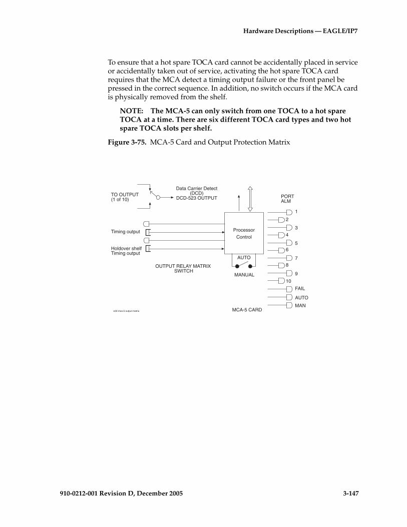
Hardware Descriptions — EAGLE/IP7
910-0212-001 Revision D, December 2005 3-147
To ensure that a hot spare TOCA card cannot be accidentally placed in service or accidentally taken out of service, activating the hot spare TOCA card requires that the MCA detect a timing output failure or the front panel be pressed in the correct sequence. In addition, no switch occurs if the MCA card is physically removed from the shelf.
NOTE: The MCA-5 can only switch from one TOCA to a hot spare TOCA at a time. There are six different TOCA card types and two hot spare TOCA slots per shelf.
Figure 3-75. MCA-5 Card and Output Protection Matrix
Processor
Control
AUTO
MANUAL
PORTALM
FAIL
AUTO
MAN
OUTPUT RELAY MATRIX SWITCH
Timing output
Holdover shelfTiming output
TO OUTPUT(1 of 10)
1
2
3
4
56
78
9
10
Data Carrier Detect(DCD)
DCD-523 OUTPUT
MCA-5 CARDe30 mca-5 output matrix
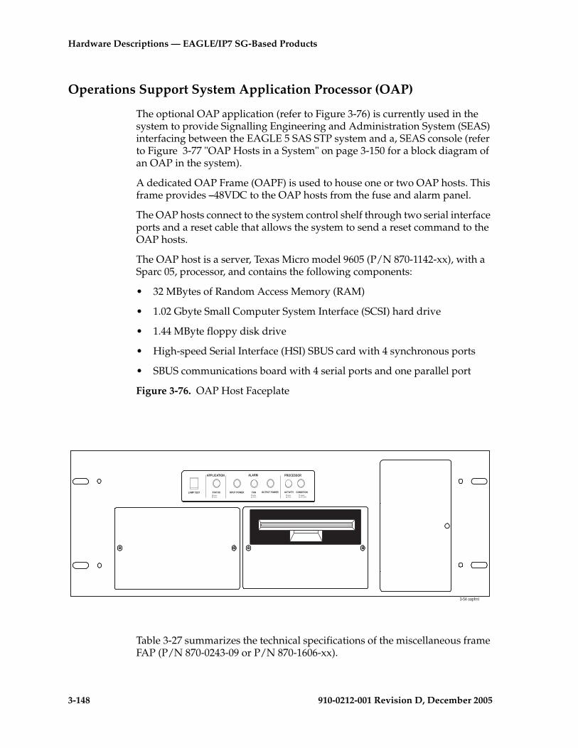
3-148 910-0212-001 Revision D, December 2005
Hardware Descriptions — EAGLE/IP7 SG-Based Products
Operations Support System Application Processor (OAP)
The optional OAP application (refer to Figure 3-76) is currently used in the system to provide Signalling Engineering and Administration System (SEAS) interfacing between the EAGLE 5 SAS STP system and a, SEAS console (refer to Figure 3-77 "OAP Hosts in a System" on page 3-150 for a block diagram of an OAP in the system).
A dedicated OAP Frame (OAPF) is used to house one or two OAP hosts. This frame provides –48VDC to the OAP hosts from the fuse and alarm panel.
The OAP hosts connect to the system control shelf through two serial interface ports and a reset cable that allows the system to send a reset command to the OAP hosts.
The OAP host is a server, Texas Micro model 9605 (P/N 870-1142-xx), with a Sparc 05, processor, and contains the following components:
• 32 MBytes of Random Access Memory (RAM)
• 1.02 Gbyte Small Computer System Interface (SCSI) hard drive
• 1.44 MByte floppy disk drive
• High-speed Serial Interface (HSI) SBUS card with 4 synchronous ports
• SBUS communications board with 4 serial ports and one parallel port
Figure 3-76. OAP Host Faceplate
Table 3-27 summarizes the technical specifications of the miscellaneous frame FAP (P/N 870-0243-09 or P/N 870-1606-xx).
���������/ ����� ��������
��������� ������ �/������2�� 1�/ ���������2�� ������0 �/�����/�%��>�,������
�%��>�,������
�%��>�,������
)���6$(��'�%��>�
�������,���
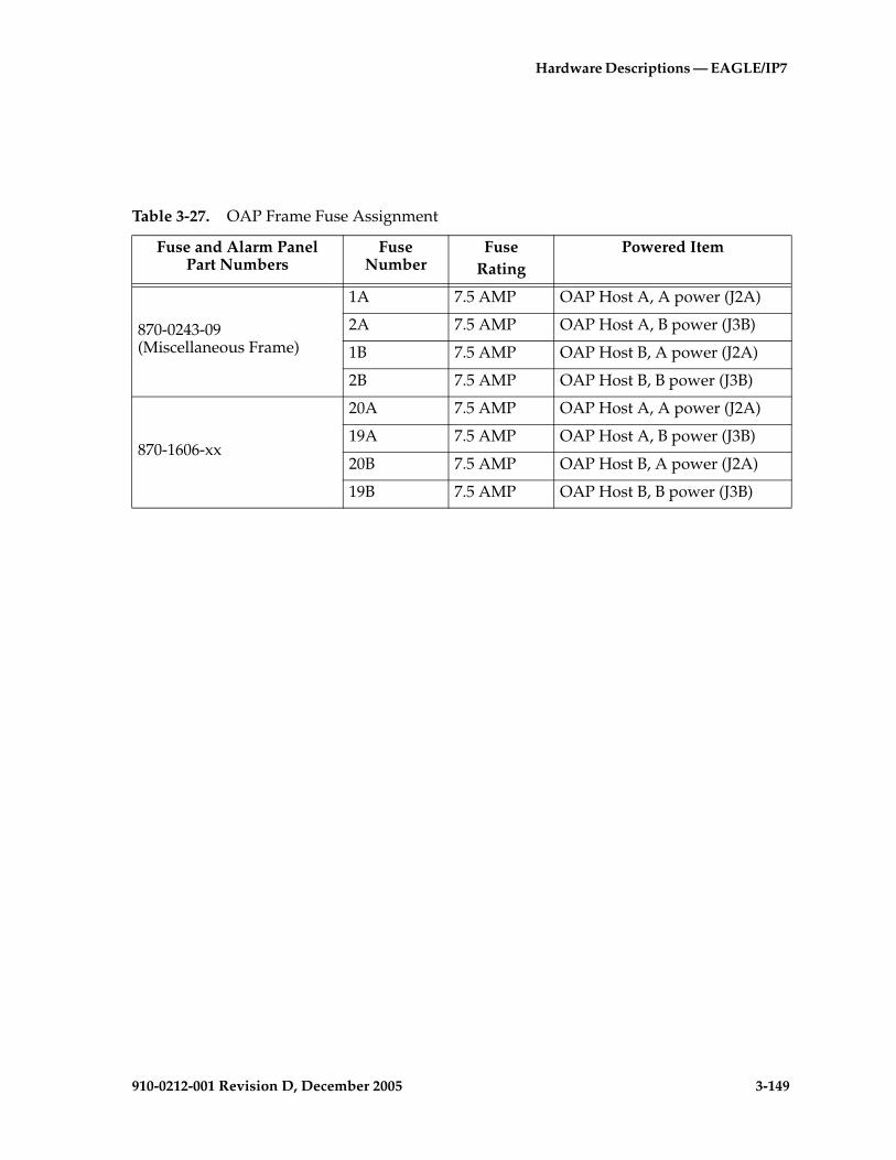
Hardware Descriptions — EAGLE/IP7
910-0212-001 Revision D, December 2005 3-149
Table 3-27. OAP Frame Fuse Assignment
Fuse and Alarm PanelPart Numbers
Fuse Number
FuseRating
Powered Item
870-0243-09(Miscellaneous Frame)
1A 7.5 AMP OAP Host A, A power (J2A)
2A 7.5 AMP OAP Host A, B power (J3B)
1B 7.5 AMP OAP Host B, A power (J2A)
2B 7.5 AMP OAP Host B, B power (J3B)
870-1606-xx
20A 7.5 AMP OAP Host A, A power (J2A)
19A 7.5 AMP OAP Host A, B power (J3B)
20B 7.5 AMP OAP Host B, A power (J2A)
19B 7.5 AMP OAP Host B, B power (J3B)

3-150 910-0212-001 Revision D, December 2005
Hardware Descriptions — EAGLE/IP7 SG-Based Products
Figure 3-77. OAP Hosts in a System
Embedded OAP (EOAP)
The optional Embedded Operations Support System Application Host Processors are currently used to support the EOAP application providing Signaling and Engineering Administration System (SEAS) interfacing between the EAGLE 5 SAS STP system and a SEAS console through an X.25 network (refer to Figure 3-79 "EOAP Hosts in a System" on page 3-152 for a block diagram of an EOAP in the system). The board suite (P/N 890-1051-01) is for a dual host configuration and the board suite (P/N 890-1110-01) is for a single host configuration.
A dedicated OAP Frame (OAPF) is used to house one or two EOAP host processor assemblies. The OAPF provides –48VDC to the EOAP from its fuse and alarm panel.
Control Shelf
Serial port
Serial port
Serial port
VT 520 terminal
OAP
OAP
Asynchcommunications
Asynchcommunications
LSMS
modemAsynch
SEAS
SEAC
modemAsynch
X.25modem
X.25modem
Maintenancecenter
Server
Disk array
Processor
oapblk3
Ethernetinterface
Signaling and Engineering Administration System (SEAS)
Asynch
Asynch
Asynch
Asynch
Synch
Synch
Disk array
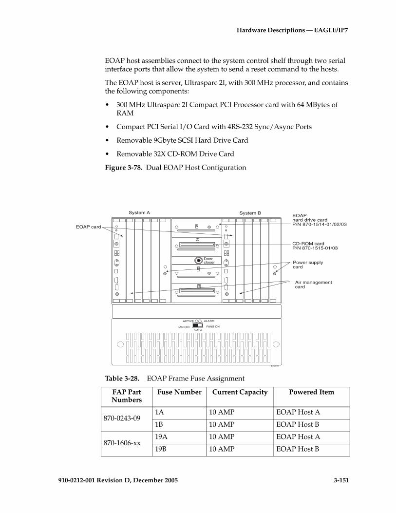
Hardware Descriptions — EAGLE/IP7
910-0212-001 Revision D, December 2005 3-151
EOAP host assemblies connect to the system control shelf through two serial interface ports that allow the system to send a reset command to the hosts.
The EOAP host is server, Ultrasparc 2I, with 300 MHz processor, and contains the following components:
• 300 MHz Ultrasparc 2I Compact PCI Processor card with 64 MBytes of RAM
• Compact PCI Serial I/O Card with 4RS-232 Sync/Async Ports
• Removable 9Gbyte SCSI Hard Drive Card
• Removable 32X CD-ROM Drive Card
Figure 3-78. Dual EOAP Host Configuration
EOAPhard drive cardP/N 870-1514-01/02/03
CD-ROM cardP/N 870-1515-01/03
System A System B
Eoapfrnt
A
A
B
B
Doorcloser Power supply
card
Air managementcard
EOAP card
ACTIVE ALARM
FAN OFF FANS ONAUTO
Table 3-28. EOAP Frame Fuse Assignment
FAP Part Numbers
Fuse Number Current Capacity Powered Item
870-0243-091A 10 AMP EOAP Host A
1B 10 AMP EOAP Host B
870-1606-xx19A 10 AMP EOAP Host A
19B 10 AMP EOAP Host B
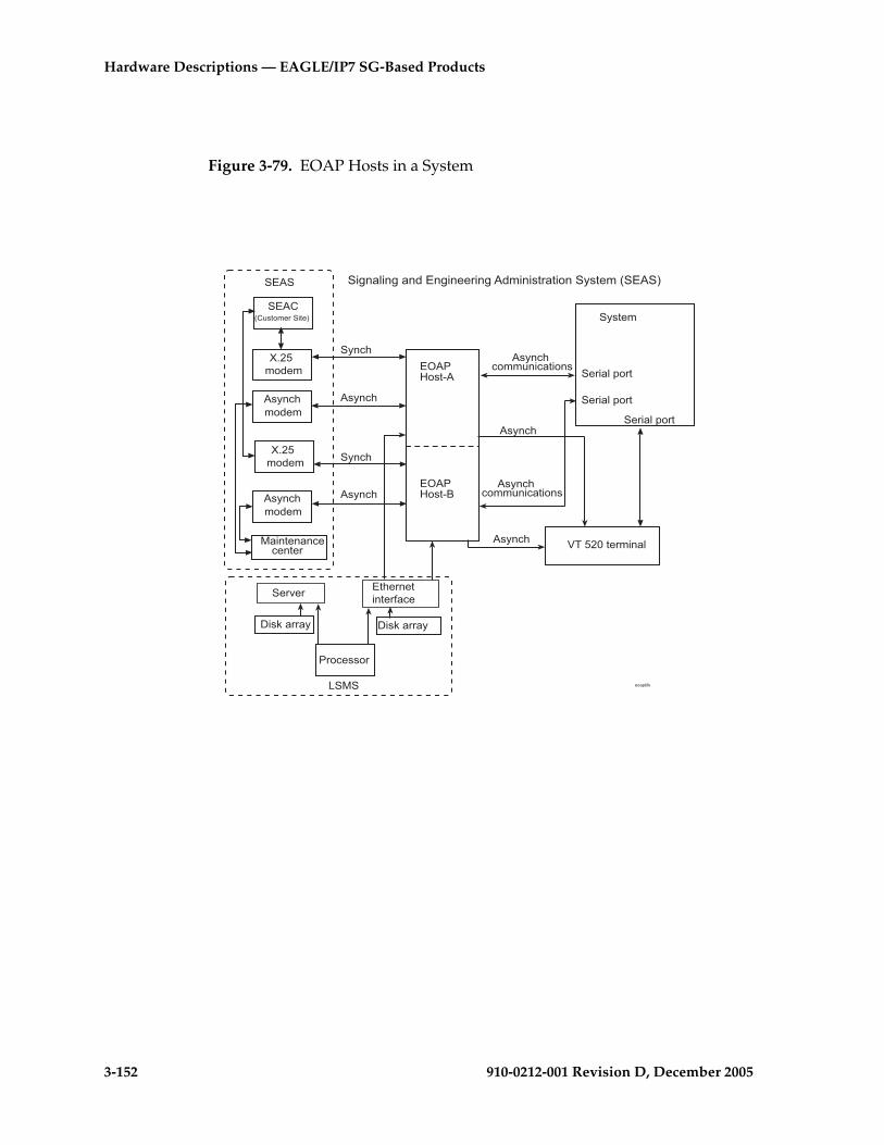
3-152 910-0212-001 Revision D, December 2005
Hardware Descriptions — EAGLE/IP7 SG-Based Products
Figure 3-79. EOAP Hosts in a System
/2 �=�)��
/2 �=�)��!
�()��*
����������
����������
����������
7�������*����
)(�%�%�**���%�����)
)(�%�%�**���%�����)
"� �
*�6�* )(�%�
�/ �
�/ �
*�6�* )(�%�
?��*�6�*
?��*�6�*
��������%�%�����
���>��
4�)&����( 4�)&����(
���%�))��
����$�&
/������������,�%�
��8�����8��6/�8�������8 6*���)��������()��*9�/ �:
)(�%�
)(�%�
)(�%�
)(�%�
�(�%�
�(�%�
9��)��*������:
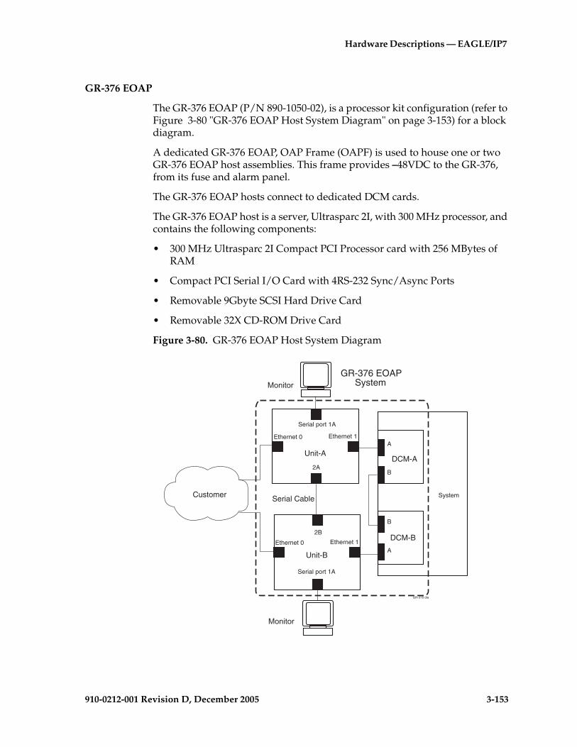
Hardware Descriptions — EAGLE/IP7
910-0212-001 Revision D, December 2005 3-153
GR-376 EOAP
The GR-376 EOAP (P/N 890-1050-02), is a processor kit configuration (refer to Figure 3-80 "GR-376 EOAP Host System Diagram" on page 3-153) for a block diagram.
A dedicated GR-376 EOAP, OAP Frame (OAPF) is used to house one or two GR-376 EOAP host assemblies. This frame provides –48VDC to the GR-376, from its fuse and alarm panel.
The GR-376 EOAP hosts connect to dedicated DCM cards.
The GR-376 EOAP host is a server, Ultrasparc 2I, with 300 MHz processor, and contains the following components:
• 300 MHz Ultrasparc 2I Compact PCI Processor card with 256 MBytes of RAM
• Compact PCI Serial I/O Card with 4RS-232 Sync/Async Ports
• Removable 9Gbyte SCSI Hard Drive Card
• Removable 32X CD-ROM Drive Card
Figure 3-80. GR-376 EOAP Host System Diagram
DCM-A
DCM-B
System
A
B
B
A
Unit-A
2A
Ethernet 1Ethernet 0
Serial port 1A
Unit-B
2B
Ethernet 1Ethernet 0
Serial port 1A
Serial CableCustomer
�"!��"$
�"!��"$
GR-376 EOAPSystem
GR-376 dia
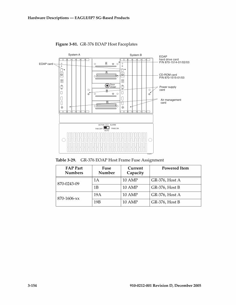
3-154 910-0212-001 Revision D, December 2005
Hardware Descriptions — EAGLE/IP7 SG-Based Products
Figure 3-81. GR-376 EOAP Host Faceplates
EOAPhard drive cardP/N 870-1514-01/02/03
CD-ROM cardP/N 870-1515-01/03
System A System B
Eoapfrnt
A
A
B
B
Doorcloser Power supply
card
Air managementcard
EOAP card
ACTIVE ALARM
FAN OFF FANS ONAUTO
Table 3-29. GR-376 EOAP Host Frame Fuse Assignment
FAP Part Numbers
Fuse Number
Current Capacity
Powered Item
870-0243-091A 10 AMP GR-376, Host A
1B 10 AMP GR-376, Host B
870-1606-xx19A 10 AMP GR-376, Host A
19B 10 AMP GR-376, Host B

910-0212-001 Revision D, December 2005 4-1
4
Hardware Descriptions —OEM-Based Products
OEM-Based Product Descriptions .................................................................4–3
Frames .........................................................................................................4–3
ASi 4000 SCP System ................................................................................4–3
Multi-Purpose Server (MPS) System ....................................................4–11
AXi Systems..............................................................................................4–14
OEM-Based Product Elements .....................................................................4–21
OEM-Based Servers .......................................................................................4–21
ASi 4000 SCP Host Servers.....................................................................4–21
MPS Host Servers ....................................................................................4–25
AXi Servers ...............................................................................................4–33
IP7 Front End (Optional) ........................................................................4–44
Operations Support System Application Processor (OAP) Host Server (Optional) .........................................................................4–46
OEM-Based Networking Elements .............................................................4–47
Ethernet Hubs ..........................................................................................4–47
Routers ......................................................................................................4–48
Ethernet Switches ....................................................................................4–50
OEM-Based Peripheral Elements ..........................................................4–52

4-2 910-0212-001 Revision D, December 2005
Hardware Descriptions — OEM-Based Products
OEM-Based Peripheral Elements ................................................................ 4–52
Breaker Panels ......................................................................................... 4–52
Eight-Port Connector Box ...................................................................... 4–55

Hardware Descriptions — OEM-Based Prod-
910-0212-001 Revision D, December 2005 4-3
OEM-Based Product Descriptions
Original Equipment Manufacturer (OEM)-based products use Common Off-The-Shelf (COTS) components configured in a Tekelec standard or heavy-duty frame. Systems are configured at Tekelec for NEBS compliance and typically have redundant components for reliability and maintainability. OEM-based products support application specific services that interact with the SS7 and IP networks. OEM-based products described in this chapter include the:
• ASi 4000 SCP
• Multi-Platform Server (MPS)
• Extended Services Platform (ESP)
• 56 Systems
NOTE: Elements used in OEM-based products have components configured by Tekelec to conform to Network Equipment-Building System (NEBS) generic equipment requirements.
Frames
The system uses standard 7-foot high, 26-inch wide frames (outside dimension). These floor mounted frames are constructed from channel steel and painted with electrostatic powder.
NOTE: A heavy-duty frame with the capability to support the greater weight of COTS equipment is shipped with all new systems. The generic frame is no longer being shipped but is supported in the documentation.
topple
TOPPLE DANGER: Systems with slide shelf mounted equipment must also be anchored to the overhead cable racks. Before beginning installation, ensure the frame is properly secured to the floor and overhead cable racks to prevent the frame from tipping over when the server slide shelves are extended.
ASi 4000 SCP System
The ASi 4000 SCP system provides application-specific services to customer networks. ASi 4000 SCP systems are mounted in standard-size frames used in telecommunications equipment and powered by nominal -48 VDC redundant sources.
The ASi 4000 SCP system can be configured in four variants to provide specific services, accessibility, and reliability. Hardware components are described in the following sections.

4-4 910-0212-001 Revision D, December 2005
Hardware Descriptions — OEM-Based Products
ASi 4000 SCP System Components
The ASi 4000 SCP system was originally installed in a general purpose frame. Figure 4-1 on page 4-5 illustrates an ASi 4000 SCP system installed in a general purpose frame. Figures 4-2, 4-3, 4-4, and 4-5 show the four configurations of the ASi 4000 SCP installed in the new heavy-duty frame. This section describes the hardware components of the four configurations of an ASi 4000 SCP and the part numbers when installed in either frame. The ASi 4000 SCP product family includes:
• ASi 4000 SCP with optional IP7 Front End and two Servers
• Installed in a general purpose frame (P/N 890-1302-01)
• Installed in a heavy-duty frame (P/N 890-1376-01)
• ASi 4000 SCP with two Servers and no IP7 Front End
• Installed in a general purpose frame (P/N 890-1302-02)
• Installed in a heavy-duty frame (P/N 890-1376-02)
• ASi 4000 SCP with Single Server and no IP7 Front End
• Installed in a general purpose frame (P/N 890-1302-03)
• Installed in a heavy-duty frame (P/N 890-1376-03)
• ASi 4000 SCP with Single Server and IP7 Front End
• Installed in a general purpose frame (P/N 890-1302-04)
• Installed in a heavy-duty frame (P/N 890-1376-04)
NOTE: In the following figures, the ASi 4000 SCP frames are shown without the doors or side panels for clarity.
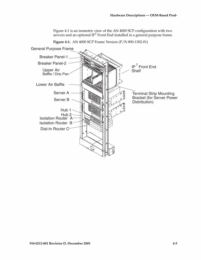
Hardware Descriptions — OEM-Based Prod-
910-0212-001 Revision D, December 2005 4-5
Figure 4-1 is an isometric view of the ASi 4000 SCP configuration with two servers and an optional IP7 Front End installed in a general purpose frame.
Figure 4-1. ASi 4000 SCP Frame Version (P/N 890-1302-01)
General Purpose Frame
Breaker Panel-1
Lower Air Baffle
Server A
Hub 1Hub 2
Dial-In Router C
Isolation Router AIsolation Router B
IP Front EndShelf
Breaker Panel-2
Terminal Strip MountingBracket (for Server PowerDistribution)
Upper Air������������ ��
Server B
7

4-6 910-0212-001 Revision D, December 2005
Hardware Descriptions — OEM-Based Products
Figure 4-2 is an isometric view of the ASi 4000 SCP configuration with two servers and an optional IP7 Front End installed in a heavy-duty frame.
Figure 4-2. ASi 4000 SCP Frame Version (P/N 890-1376-01)
Breaker Panel-1
Lower Air Baffle
Server A
Server B
Hub 1Hub 2
Router C(Dial-in)
Router A(Isolation)
Router B(Isolation)
IP7 Front EndUpper Air Baffle/Drip Pan
Breaker Panel-2
Terminal Strip MountingBracket (for Server
Power Distribution)
asi frame 1
Seismic Frame

Hardware Descriptions — OEM-Based Prod-
910-0212-001 Revision D, December 2005 4-7
Figure 4-3 is an isometric view of the ASi 4000 SCP configuration with two servers installed in a heavy-duty frame.
Figure 4-3. ASi 4000 SCP Frame Version (P/N 890-1376-02)
Seismic Frame
Breaker Panel-1
Server A
Server B
Hub 1Hub 2
Router C(Dial-in)
Router A(Isolation)
Router B(Isolation)
Upper Air Baffle/Drip Pan
Breaker Panel-2
Terminal Strip MountingBracket (for ServerPower Distribution)
asi frame 2

4-8 910-0212-001 Revision D, December 2005
Hardware Descriptions — OEM-Based Products
Figure 4-4 is an isometric view of the ASi 4000 SCP configuration with one server installed in a heavy-duty frame.
Figure 4-4. ASi 4000 SCP Frame Version (P/N 890-1376-03)
Seismic Frame
Breaker Panel-1
Server A
Hub 1Hub 2
Router C(Dial-in)
Router A(Isolation)
Router B(Isolation)
Upper Air Baffle/Drip Pan
Breaker Panel-2
Terminal Strip MountingBracket (for ServerPower Distribution)
asi frame 3
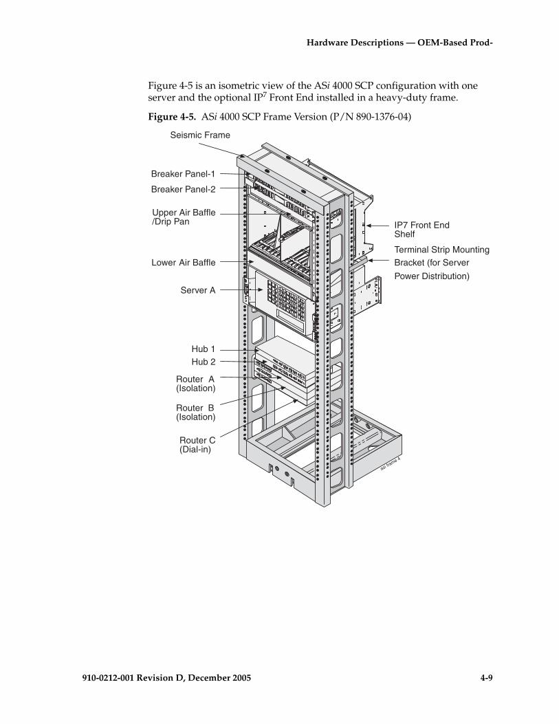
Hardware Descriptions — OEM-Based Prod-
910-0212-001 Revision D, December 2005 4-9
Figure 4-5 is an isometric view of the ASi 4000 SCP configuration with one server and the optional IP7 Front End installed in a heavy-duty frame.
Figure 4-5. ASi 4000 SCP Frame Version (P/N 890-1376-04)
asi frame 4
Breaker Panel-1
Lower Air Baffle
Server A
Hub 1Hub 2
Router C(Dial-in)
Router A(Isolation)
Router B(Isolation)
IP7 Front EndShelf
Upper Air Baffle/Drip Pan
Breaker Panel-2
Terminal Strip MountingBracket (for Server
Power Distribution)
Seismic Frame
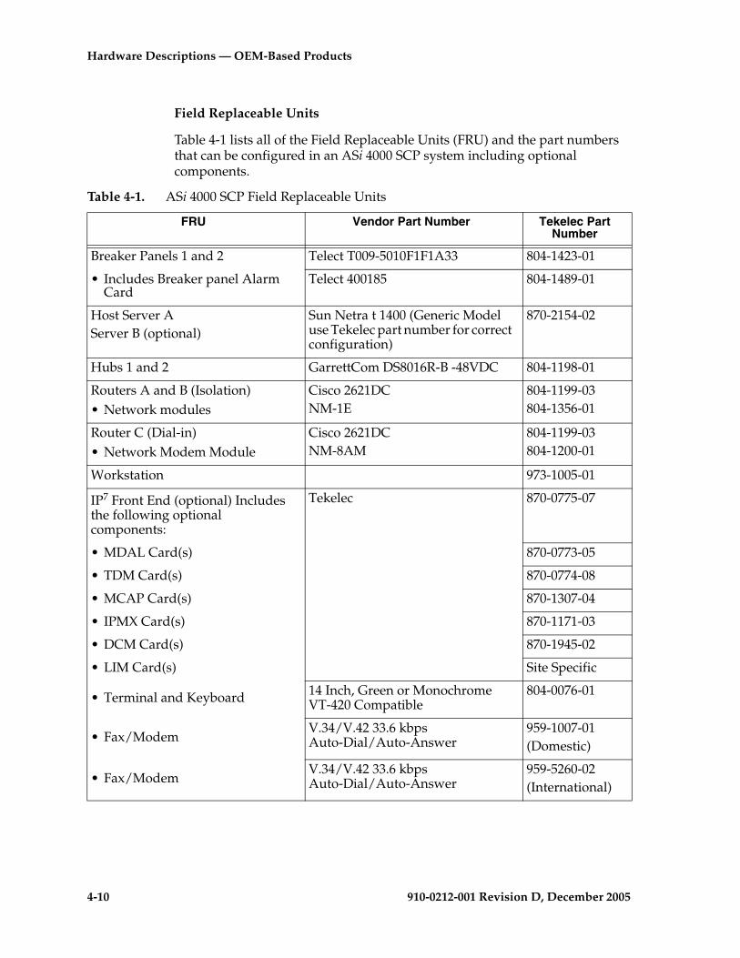
4-10 910-0212-001 Revision D, December 2005
Hardware Descriptions — OEM-Based Products
Field Replaceable Units
Table 4-1 lists all of the Field Replaceable Units (FRU) and the part numbers that can be configured in an ASi 4000 SCP system including optional components.
Table 4-1. ASi 4000 SCP Field Replaceable Units
FRU Vendor Part Number Tekelec Part Number
Breaker Panels 1 and 2 Telect T009-5010F1F1A33 804-1423-01
• Includes Breaker panel Alarm Card
Telect 400185 804-1489-01
Host Server A Server B (optional)
Sun Netra t 1400 (Generic Model use Tekelec part number for correct configuration)
870-2154-02
Hubs 1 and 2 GarrettCom DS8016R-B -48VDC 804-1198-01
Routers A and B (Isolation)• Network modules
Cisco 2621DC NM-1E
804-1199-03804-1356-01
Router C (Dial-in)• Network Modem Module
Cisco 2621DCNM-8AM
804-1199-03804-1200-01
Workstation 973-1005-01
IP7 Front End (optional) Includes the following optional components:
Tekelec 870-0775-07
• MDAL Card(s) 870-0773-05
• TDM Card(s) 870-0774-08
• MCAP Card(s) 870-1307-04
• IPMX Card(s) 870-1171-03
• DCM Card(s) 870-1945-02
• LIM Card(s) Site Specific
• Terminal and Keyboard 14 Inch, Green or Monochrome VT-420 Compatible
804-0076-01
• Fax/ModemV.34/V.42 33.6 kbps Auto-Dial/Auto-Answer
959-1007-01(Domestic)
• Fax/ModemV.34/V.42 33.6 kbps Auto-Dial/Auto-Answer
959-5260-02(International)
Hardware Descriptions — OEM-Based Prod-
910-0212-001 Revision D, December 2005 4-11
Multi-Purpose Server (MPS) System
NOTE: Beginning in EAGLE release 30.1, MPS systems running EPAP 4.0 are hosted on the Tekelec 1000 Applications Server. Existing MPS systems running on SUN servers will continue to be supported. Customers wanting to upgrade to the functionality of MPS/EPAP 4.0 are required to install the Tekelec 1000 Applications Server. For more information refer to the “Tekelec 1000 Applications Server Hardware Manual.”
This section provides an overview of the Multi-Purpose Server (MPS) hardware. This section includes a description of MPS hardware components and an overview of the disks and file systems. Figure 4-6 "MPS Hardware Overview" on page 4-12 illustrates the following equipment.
• Two Breaker Panels
• One Drip Tray
• Four Hubs
• Two MPS Servers
• One 8-Port Connector Box (connects by a 40-inch cable the to Sun SAI/P card)
• One General Purpose Frame
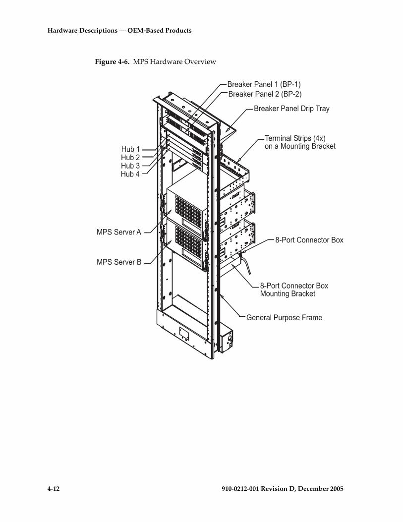
4-12 910-0212-001 Revision D, December 2005
Hardware Descriptions — OEM-Based Products
Figure 4-6. MPS Hardware Overview
�$��2�$���!�'���3��1�4�$��2�$���!�'���3��1�4
-�$%�!�'���$�(��3�54"!����"#!��!6��$��2��
�1�"$��+"!!���"$��"5
�1�"$��+"!!���"$��"5�"#!��!6��$��2��
������$)�$�.
#7�� #7�� #7�� #7��
������$)�$��
8�!�$�'��#$("����$�%�
�$��2�$���!�'��$�(�-$�9
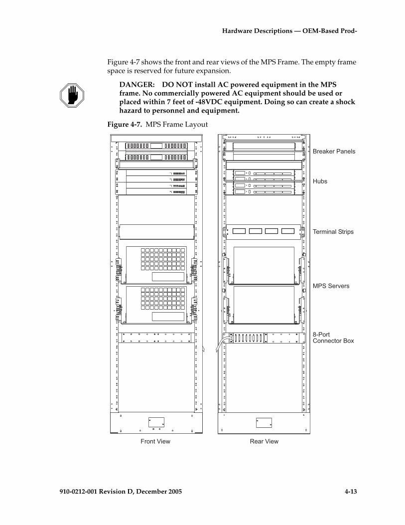
Hardware Descriptions — OEM-Based Prod-
910-0212-001 Revision D, December 2005 4-13
Figure 4-7 shows the front and rear views of the MPS Frame. The empty frame space is reserved for future expansion.
DANGER: DO NOT install AC powered equipment in the MPS frame. No commercially powered AC equipment should be used or placed within 7 feet of -48VDC equipment. Doing so can create a shock hazard to personnel and equipment.
Figure 4-7. MPS Frame Layout
�$"!��:��& ,��$�:��&
�$��2�$���!�'�
#7�
-�$%�!�'���$�(�
������$)�$�
�1�"$�+"!!���"$��"5

4-14 910-0212-001 Revision D, December 2005
Hardware Descriptions — OEM-Based Products
AXi Systems
AXi Release 1.0 systems use OEM components configured in application processor frames. AXi Release 1.0 system configurations are very flexible to allow for scalability and ease of upgrades. The AXi system can be ordered as a stand-alone product or as part of a larger system. For additional information see the section “AXi Systems” on page 4-14. AXi Release 1.0 systems are configured in the following basic frame types:
• An Application Frame 1 (APP1)
• A Network Frame (NET)
AXi Release 1.0 system models are configured with using the following frames:
• The AXi 500 (Small System) is configured in single Network Frame. The AXi 500 system does not have Server C (the Media Server) installed.
• The AXi 1000 (Medium System) and AXi 2000 (Large System) are configured with both an Application Frame 1 (APP1) and a NET Frame.
Components
All AXi Release 1.0 systems are configured as fully redundant systems. All components, except the Dial-in Router, are configured in pairs. All components except the Dial-in router are redundantly powered by separate power sources.
AXi frames can hold up to three Sun Netra t 1400 servers, two Sun st A1000 RAID arrays and two Cisco 2924XL LAN switches. From the basic frame types a number of AXi Release 1.0 system sizes can be configured. For a specific AXi system configuration each server position can be filled with an Application Server (AS), Media Server (MS), Network Server (NS) or left blank. All servers are based on Sun Netra t 1400s with differing configuration requirements. Server types are defined according to the function they serve, location in specific frames and interconnections. The physical configuration of components in medium (AXi 1000) and large (AXi 2000) systems are similar, the difference being in the number of central processing units (CPU) and the amount of memory installed on each server.
Functional and Hardware Differences of AXi Servers
All servers use ethernet CAT5 connections to communicate with the internal LANs or to the customer’s network. Determined by the function of a server and the location in the AXi frames different communication interfaces may be required. The function of a server also determines if the presence of a back-up media (tape drive) is required for services or upgrades.
All servers have the TTYA and TTYB serial console interfaces connected together to provide telnet access with the TIP command.

Hardware Descriptions — OEM-Based Prod-
910-0212-001 Revision D, December 2005 4-15
For additional information about AXi server configuration differences see “AXi Servers” on page 4-33. The following sections describe the AXi servers by the function they perform.
Application Servers
The Application Server (AS) is the primary interface between the other servers and the customer network when used in a system. When a server functions as an AS an adjoining RAID array is required. A RAID array consists of redundant disk storage systems that contain the application services databases. To communicate with the RAID units the AS require a SCSI interface card and adapter. AS have redundant internal disks configured in a mirrored scheme and always have a backup tape drive installed. AS are designed to function in an active/standby mode of operation in the AXi 1000 and AXi 2000 systems.
Network Servers
Servers functioning as Network Servers (NS) provide network-level services including translations and routing as well as VPN and private dialing plans. NS A (the top Network Server) also provides remote telnet communication capabilities to the AXi system consoles from a dedicated access line through a Dial-in Router. In the NET frame, NS A has an additional serial interface card installed to provide this capability. The Dial-in Router is located above NS A in the NET frame. NS also require a backup tape drive. NS operate in a load sharing mode and are used in all AXi systems.
NOTE: In AXi 500 single-frame systems the Network Servers communicate directly with the customers network.
Media Servers
Media Servers (MS) provide media resources including digit detection, announcements, voice messaging and media mixing functions. MS are configured in N+1 groups for redundancy. A single MS has the capacity to handle up to 500 Interactive Voice Response (IVR) sessions. In AXi 1000 and AXi 2000 systems two MS are configured. The MS are not used in the small AXi 500 VPN system. MS do not require a backup tape drive.
Common Components on AXi Systems
In dual-frame systems All servers communicate through the ethernet LAN switches located in the APP1 frame. In AXi 1000 and AXi 2000 systems the LAN switches provide the communications path to the customers network. For additional information about the LAN switches used in the AXi 1000 and AXi 2000 systems see “Ethernet Switches” on page 4-50.
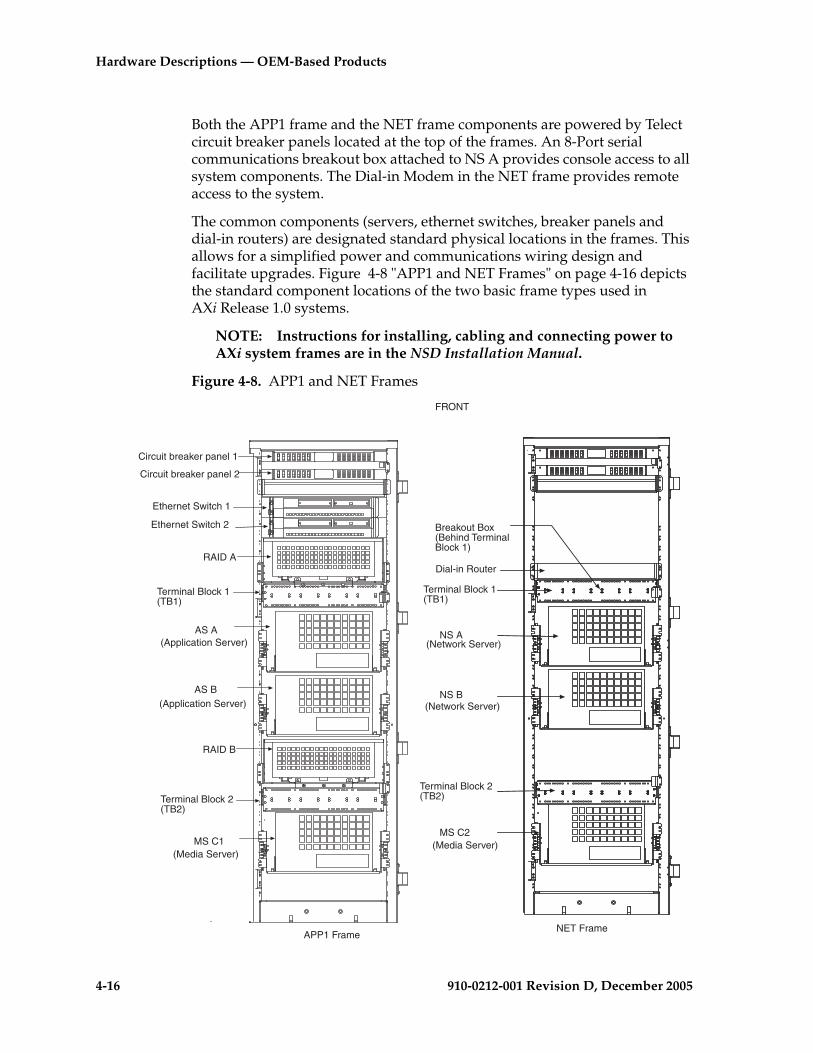
4-16 910-0212-001 Revision D, December 2005
Hardware Descriptions — OEM-Based Products
Both the APP1 frame and the NET frame components are powered by Telect circuit breaker panels located at the top of the frames. An 8-Port serial communications breakout box attached to NS A provides console access to all system components. The Dial-in Modem in the NET frame provides remote access to the system.
The common components (servers, ethernet switches, breaker panels and dial-in routers) are designated standard physical locations in the frames. This allows for a simplified power and communications wiring design and facilitate upgrades. Figure 4-8 "APP1 and NET Frames" on page 4-16 depicts the standard component locations of the two basic frame types used in AXi Release 1.0 systems.
NOTE: Instructions for installing, cabling and connecting power to AXi system frames are in the NSD Installation Manual.
Figure 4-8. APP1 and NET Frames
FRONT
Circuit breaker panel 1
Circuit breaker panel 2
Ethernet Switch 1
Ethernet Switch 2
RAID A
Terminal Block 1(TB1)
AS A
AS B
RAID B
Terminal Block 2(TB2)
MS C1
APP1 Frame
(Application Server)
(Media Server)
NET Frame
Terminal Block 1(TB1)
NS A
NS B
MS C2
Dial-in Router
Breakout Box(Behind TerminalBlock 1)
(Application Server)
(Network Server)
(Network Server)
(Media Server)
Terminal Block 2(TB2)
Hardware Descriptions — OEM-Based Prod-
910-0212-001 Revision D, December 2005 4-17
AXi System Types
AXi Release 1.0 systems can be configured as Virtual Private Network (VPN) small systems (AXi 500) with two Network Servers in a single frame or as medium (AXi 1000) or large (AXi 2000) systems with six servers in two frames. The difference between the AXi 1000 and AXi 2000 systems is in the number of central processing units (CPU) configured and the amount of memory installed in each server. Upgrade paths exist to increase the small VPN system functionality to a medium system and the medium system to the large system. Scalability of future AXi systems will include additional frames and functionality.
VPN Systems (AXi 500)
The Virtual Private Network (VPN) system is a small AXi Release 1.0 system that addresses the requirements in the Inter-Exchange Carrier (IXC) market. The VPN consists of two Network Servers (Netra t 1400s with dual 440 MHz processors, 2GB of RAM, and (2) 36GB hard drives) mounted in a single NET frame.
The upper Network Server (NS A) is configured with an additional asynchronous interface card in slot two. This interface is used for local and remote console access to the various frame components. NS have the local console ports connected together to allow telnet access to the mate NS. Dial-in access to the VPN system is provided by a Cisco 2621 Router. For additional information about the Dial-in Router see “Routers” on page 4-48.
In VPN systems the Network servers communicate with the customers network through ethernet ports (hme0 and qfe0).
In Figure 4-9 "VPN System in the NET Frame" on page 4-18, note the VPN system does not use the Media server “C”. In both the AXi 1000 and AXi 2000 systems the NET frame is configured with the “C” servers functioning as Media Servers.
NOTE 1: The Media Server mounting hardware, power terminal block and wiring are included in the NET frame to facilitate upgrading from the AXi 500 to the AXi 1000 system.
NOTE 2: Upgrading from an AXi 500 to an AXi 1000 requires installing an additional APP1 frame and adding a MS in the NET frame. See Figure 4-10 "Medium (AXi 1000) and Large (AXi 2000) Configurations" on page 4-20 for an illustration of those systems. Upgrading from an AXi 500 to an AXi 1000 also requires changes of interface connections to the customer’s network.

4-18 910-0212-001 Revision D, December 2005
Hardware Descriptions — OEM-Based Products
Figure 4-9. VPN System in the NET Frame
NET Frame
Terminal Block 1(TB1)
Server A
Server B
Dial-in Router
Breakout Box(Behind TerminalBlock 1)
Terminal Block 2(TB2)
FRONT
Network Server
Network Server
Hardware Descriptions — OEM-Based Prod-
910-0212-001 Revision D, December 2005 4-19
Medium System (AXi 1000)
The Medium system can provide IP Centrex service to a subscriber base from 10,000 to 20,000 users. Medium systems (AXi 1000) consist of two Application Servers (AS), two Media Servers (MS), two Network Severs (NS), two LAN switches, a Dial-in Router and two RAID systems configured in two frames. The servers are Netra t1400s with dual 440MHZ processors, two GB of RAM, and two 36GB internal hard drives. Each AS is mated with one RAID system (Sun st A1000) through a SCSI interface. AS internal disks are configured for mirrored operation. In AXi systems the AS and NS have backup tape drives installed.
In AXi 1000 systems all servers (Application, Network and Media) communicate through the ethernet ports (hme0 and qfe0) to the Cisco 2924M XL LAN switches. Communication with the customer networks is through the LAN switches.
The upper Network Server (NS A) is configured with an additional asynchronous interface card. These interfaces are used for local and remote access to the server console ports through an eight-port breakout box. Remote access to the system consoles is provided by a Cisco 2621 Dial-in Router connected to a customer supplied dedicated phone line. All servers have the console ports connected together to provide telnet access to each server.
In AXi 1000 systems Media Servers are configured in an N+1 configuration. A single Media Server can handle up to 500 Interactive Voice Response sessions. The two Media Servers operate in load-sharing mode.
NOTE: AXi Medium systems are field upgradeable to AXi Large systems by adding additional CPUs and memory.
See Figure 4-10 "Medium (AXi 1000) and Large (AXi 2000) Configurations" on page 4-20 for component locations.
AXi Large System (AXi 2000)
The Large system can provide IP Centrex service to a subscriber base from 10,000 to 40,000 users. Large systems (AXi 2000) consist of two Application Servers (AS), two Media Servers (MS), two Network Severs (NS), two LAN switches, a Dial-in Router and two RAID systems configured in two frames. The servers are Netra t1400s with four 440MHZ processors, four GB of RAM, and four 36GB internal hard drives. Each AS is mated with one RAID system (Sun st A1000) through a SCSI interface. AS internal disks are configured for mirrored operation. In AXi systems the AS and NS have backup tape drives installed.
In AXi 2000 systems, all servers (Application, Network and Media) communicate through the ethernet ports (hme0 and qfe0) to the Cisco 2924M XL LAN switches. Communication with the customer networks is through the LAN switches
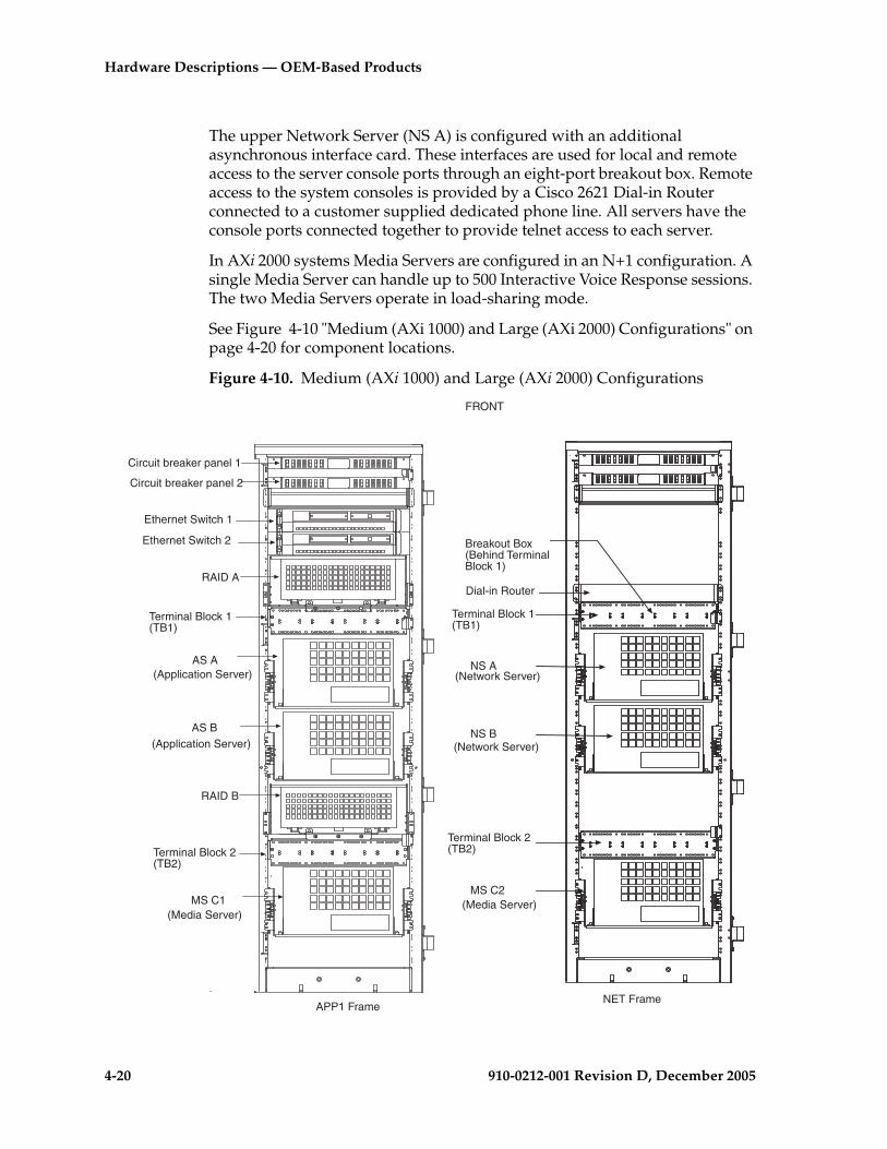
4-20 910-0212-001 Revision D, December 2005
Hardware Descriptions — OEM-Based Products
The upper Network Server (NS A) is configured with an additional asynchronous interface card. These interfaces are used for local and remote access to the server console ports through an eight-port breakout box. Remote access to the system consoles is provided by a Cisco 2621 Dial-in Router connected to a customer supplied dedicated phone line. All servers have the console ports connected together to provide telnet access to each server.
In AXi 2000 systems Media Servers are configured in an N+1 configuration. A single Media Server can handle up to 500 Interactive Voice Response sessions. The two Media Servers operate in load-sharing mode.
See Figure 4-10 "Medium (AXi 1000) and Large (AXi 2000) Configurations" on page 4-20 for component locations.
Figure 4-10. Medium (AXi 1000) and Large (AXi 2000) Configurations
FRONT
Circuit breaker panel 1
Circuit breaker panel 2
Ethernet Switch 1
Ethernet Switch 2
RAID A
Terminal Block 1(TB1)
AS A
AS B
RAID B
Terminal Block 2(TB2)
MS C1
APP1 Frame
(Application Server)
(Media Server)
NET Frame
Terminal Block 1(TB1)
NS A
NS B
MS C2
Dial-in Router
Breakout Box(Behind TerminalBlock 1)
(Application Server)
(Network Server)
(Network Server)
(Media Server)
Terminal Block 2(TB2)
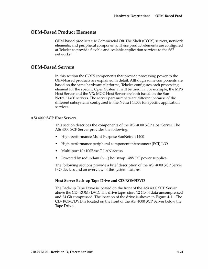
Hardware Descriptions — OEM-Based Prod-
910-0212-001 Revision D, December 2005 4-21
OEM-Based Product Elements
OEM-based products use Commercial Off-The-Shelf (COTS) servers, network elements, and peripheral components. These product elements are configured at Tekelec to provide flexible and scalable application services to the SS7 networks.
OEM-Based Servers
In this section the COTS components that provide processing power to the OEM-based products are explained in detail. Although some components are based on the same hardware platforms, Tekelec configures each processing element for the specific Open System it will be used in. For example, the MPS Host Server and the VXi MGC Host Server are both based on the Sun Netra t 1400 servers. The server part numbers are different because of the different subsystems configured in the Netra t 1400s for specific application services.
ASi 4000 SCP Host Servers
This section describes the components of the ASi 4000 SCP Host Server. The ASi 4000 SCP Server provides the following:
• High performance Multi-Purpose SunNetra t 1400
• High performance peripheral component interconnect (PCI) I/O
• Multi-port 10/100Base-T LAN access
• Powered by redundant (n+1) hot swap –48VDC power supplies
The following sections provide a brief description of the ASi 4000 SCP Server I/O devices and an overview of the system features.
Host Server Back-up Tape Drive and CD-ROM/DVD
The Back-up Tape Drive is located on the front of the ASi 4000 SCP Server above the CD- ROM/DVD. The drive tapes store 12 Gb of data uncompressed and 24 Gb compressed. The location of the drive is shown in Figure 4-11. The CD- ROM/DVD is located on the front of the ASi 4000 SCP Server below the Tape Drive.
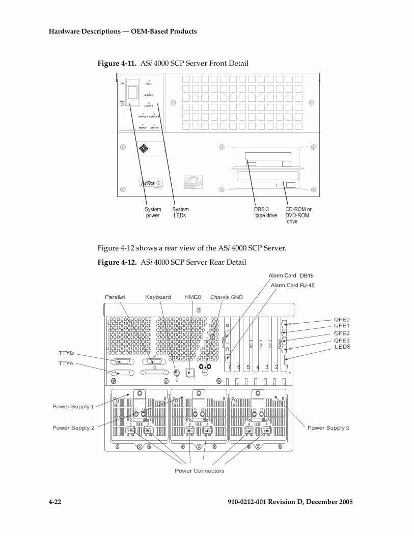
4-22 910-0212-001 Revision D, December 2005
Hardware Descriptions — OEM-Based Products
Figure 4-11. ASi 4000 SCP Server Front Detail
Figure 4-12 shows a rear view of the ASi 4000 SCP Server.
Figure 4-12. ASi 4000 SCP Server Rear Detail
�������
����������
������� ���
���������������
���������������������
.'�$% +�$
.'�$% +�$ RJ-45
DB15
�����
LEDS

Hardware Descriptions — OEM-Based Prod-
910-0212-001 Revision D, December 2005 4-23
ASi 4000 SCP Server Specifications
The server primary board contains the CPU module(s), memory, system control application-specific integrated circuits (ASICs) and I/O ASICs. Table 4-2 lists the major components of the server
Table 4-2. Server Specifications
Server Specifications ASi 4000 SCP Server
Dimensions and WeightHeight Width Depth Weight (unpackaged but fully configured)
264 mm (10.4 inches/6U)431.8 mm (17 inches)504.7 mm (19.9 inches)37 kg (81.8 lbs.)
CPUsProcessor type Clock rate CPUs provided Cache on module
UltraSPARC-II 64-bit processors 440 MHz4 4 MB Ecache
MemorySize
Memory type DIMM sizes DRAM speed Bus width
4 Gbyte
ECC2 x 256 MByte60 ns 2 x 288 bits
Storage (Internal) Bus SCSI disks
CD- ROM or DVD Tape drive
40 MB/second UltraSCSI 36.4 GByte (two 18.2 GByte, 10K-rpm disks)Removable disk drive DDS-3, 12-24 GB, 4 mm
I/O ArchitecturePCI QFE Interface Card Four 10/100BASE-T auto-negotiating
ports (QFE0-QFE3)
Networking Port TP Ethernet 100BASE-T/10BASE-T(HME0)
Operating Environment Solaris 2.6

4-24 910-0212-001 Revision D, December 2005
Hardware Descriptions — OEM-Based Products
Server Diagnostic LEDs
The LEDs on the front of the ASi 4000 SCP Server indicate the current status of the system. See Figure 4-13 for a detailed view of the Server LEDs.
Figure 4-13. ASi 4000 SCP Server LED Locations
Table 4-3 describes the LED indicators located on the front of the ASi 4000 SCP Server.
Table 4-3. Server LEDs
LED Color Description
FAULT Amber Flashes when a fan or Power Supply Unit (PSU) has failedLights continuously when the ASR watchdog times out or when it is manually switched on
ALARM 1 Amber Not Used
ALARM 2 Amber Not Used
SUPPLY A Green Lights whenever DC input A is present on all fitted PSUs
SUPPLY B Green Lights whenever DC input B is present on all fitted PSUs
POWER Green Lights at all times when the system is on
SYSTEM Green Off (or reset) during power up proceduresLights whenever UNIX is running and the alarm driver is installedNote: This LED is reset by a hardware watchdog timeout or whenever the user-defined Alarm 3 is asserted
FAULT
ALARM 1
ALARM 2
SUPPLY A SUPPLY B
POWER SYSTEM
STBY
ON
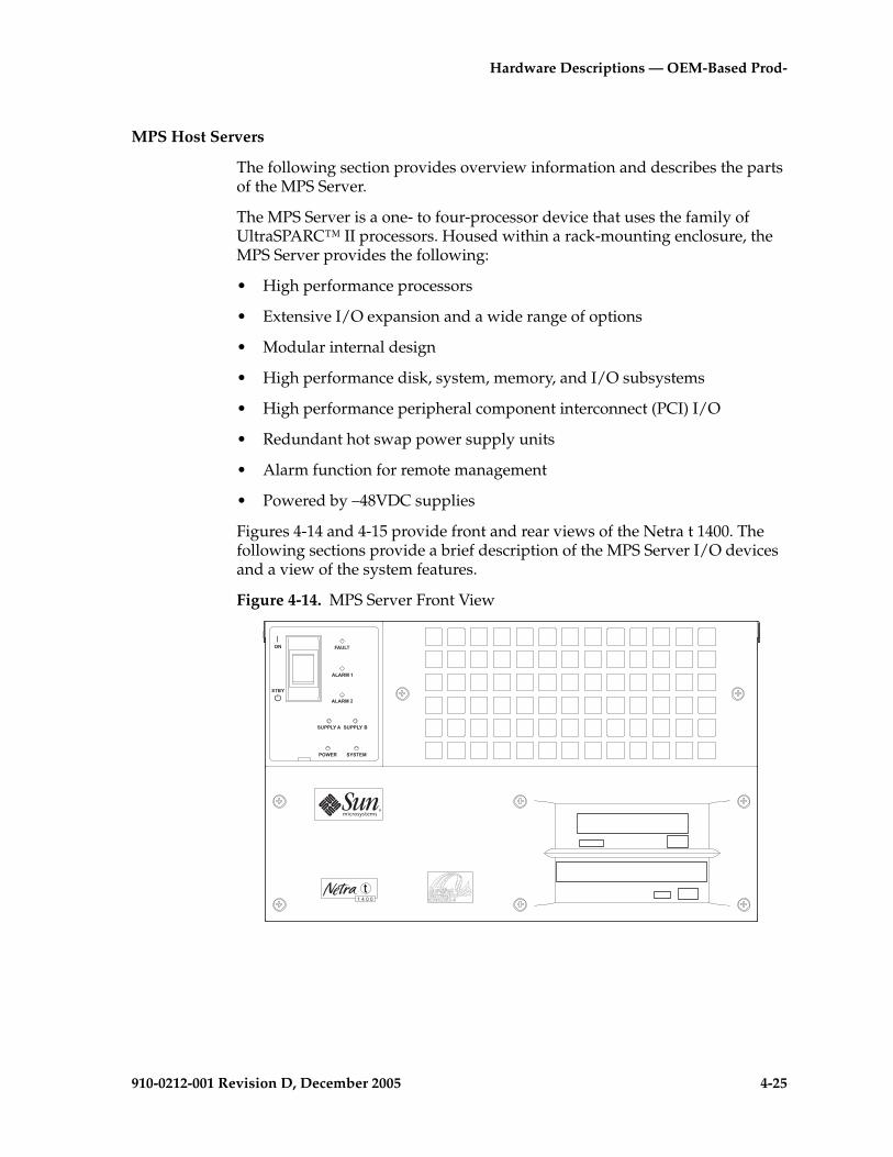
Hardware Descriptions — OEM-Based Prod-
910-0212-001 Revision D, December 2005 4-25
MPS Host Servers
The following section provides overview information and describes the parts of the MPS Server.
The MPS Server is a one- to four-processor device that uses the family of UltraSPARC™ II processors. Housed within a rack-mounting enclosure, the MPS Server provides the following:
• High performance processors
• Extensive I/O expansion and a wide range of options
• Modular internal design
• High performance disk, system, memory, and I/O subsystems
• High performance peripheral component interconnect (PCI) I/O
• Redundant hot swap power supply units
• Alarm function for remote management
• Powered by –48VDC supplies
Figures 4-14 and 4-15 provide front and rear views of the Netra t 1400. The following sections provide a brief description of the MPS Server I/O devices and a view of the system features.
Figure 4-14. MPS Server Front View
�������
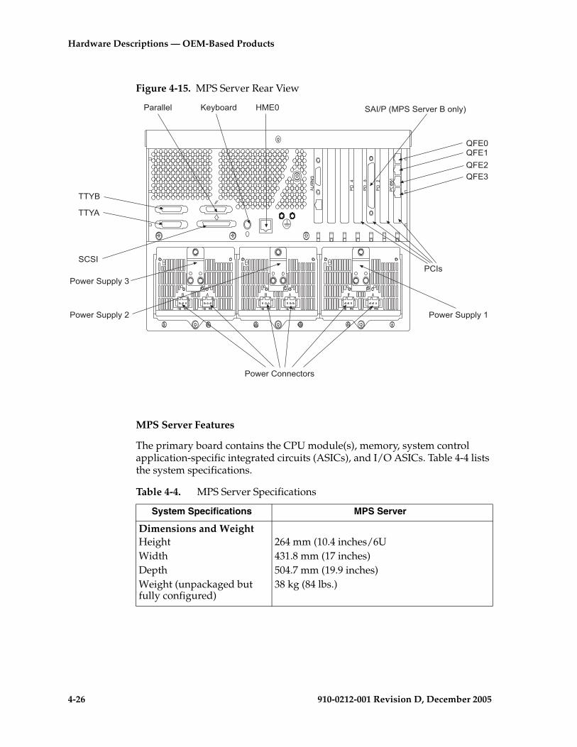
4-26 910-0212-001 Revision D, December 2005
Hardware Descriptions — OEM-Based Products
Figure 4-15. MPS Server Rear View
MPS Server Features
The primary board contains the CPU module(s), memory, system control application-specific integrated circuits (ASICs), and I/O ASICs. Table 4-4 lists the system specifications.
--;�
--;.
��� �.�<��3������$)�$���"!'94
=���=���
=���=���
��$�''�'
�+��
>�97"�$
�+��
�"&�$�+"!!���"$�
�"&�$��#(('9���"&�$��#(('9��
�"&�$��#(('9��
Table 4-4. MPS Server Specifications
System Specifications MPS Server
Dimensions and WeightHeightWidthDepthWeight (unpackaged but fully configured)
264 mm (10.4 inches/6U431.8 mm (17 inches)504.7 mm (19.9 inches)38 kg (84 lbs.)

Hardware Descriptions — OEM-Based Prod-
910-0212-001 Revision D, December 2005 4-27
CPU(EPAP/GSM/INP) Processor typeClock rateCPUs providedCache on module
UltraSPARC-II 64-bit processor440 MHz1 UltraSPARC-II processor4 MB Ecache
CPU((ELAP/LNP)Processor typeClock rateCPUs providedCache on module
UltraSPARC-II 64-bit processor440 MHz2 UltraSPARC-II processors4 MB EcacheNote: Number of CPUs provided includes upgrade kit 870-2669-02 containing one additional 440 MHz processor required for ELAP MPS servers.
Memory (EPAP/GSM/INP)SizeMemory type DIMM sizes DRAM speedBus width
1024 MBECC4 x 256 MB60 ns2 x 288 bits
Memory (ELAP/LNP)SizeMemory typeDIMM sizes DRAM speedBus width
4096 MBECC16 x 256 MB60 ns2 x 288 bitsNote: Memory size listed includes upgrade kit 870-2669-02 containing 2048MB (8 x256 MB) of memory.
Storage (Internal)Bus SCSI disksDVD ROMTape drive
40 MB/second UltraSCSI 144 GB (four 36 GB, 10K-rpm disks)DVD-ROM driveDDS-3, 12-24 GB, 4 mm
Table 4-4. MPS Server Specifications (Continued)
System Specifications MPS Server

4-28 910-0212-001 Revision D, December 2005
Hardware Descriptions — OEM-Based Products
The MPS server has these additional features:
• Rack mounting enclosure with n+1 redundant, hot-swap –48VDC power supplies
• UltraSPARC Port Architecture (UPA) coherent memory interconnect
• Use of Dual Inline Memory Module (DIMMs), with an interleaved memory system. Populating with two pairs of identical capacity DIMMs enables the memory controller to interleave and overlap, providing optimal system performance.
• 40 Mbps Fast-20 (UltraSCSI) disk subsystem supporting up to four 36 GB disk drives
• Two RS232/423 DB-25 serial ports (asynchronous protocols)
• Parallel port
• External Fast-20 (UltraSCSI) 68-pin port
• Two SCSI removable media drives and Tape Drive
• Alarm card
The alarm card has a non-volatile buffer to record recent events, monitors internal hardware devices, and controls the front panel alarm, fault, and system LEDs.
I/O ArchitecturePCI SAI Adapter Card
PCI QFE Interface CardPCI bus
Onboard Serial ports Parallel port SCSI
Connects to Eight EI4-232 ports (in 8-Port Connector box)Four 100BASE-T Ethernet portsFour PCI slots: • Two 33 MHz, 32/64-bit, 5VDC• One 33 MHz 32-bit, 5VDC• One 33/66 MHz, 64-bit, 3.3VDC DB25DB25External Fast-20 (UltraSCSI) 68-pin port
Networking Ports TP Ethernet 100BASE-T/10BASE-T
Backup and DistributionInternal DVD drive
DAT DDS-3, 12-24 GB, 4 mm
Operating Environment Solaris 7
Table 4-4. MPS Server Specifications (Continued)
System Specifications MPS Server
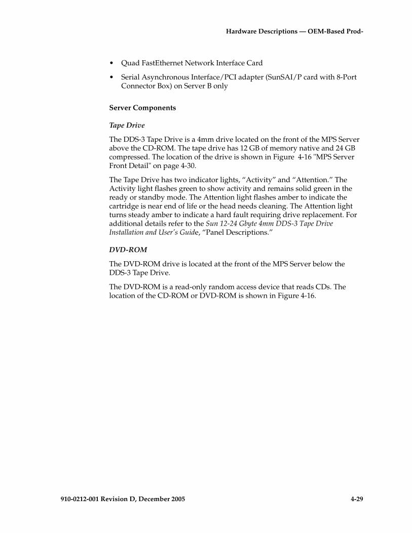
Hardware Descriptions — OEM-Based Prod-
910-0212-001 Revision D, December 2005 4-29
• Quad FastEthernet Network Interface Card
• Serial Asynchronous Interface/PCI adapter (SunSAI/P card with 8-Port Connector Box) on Server B only
Server Components
Tape Drive
The DDS-3 Tape Drive is a 4mm drive located on the front of the MPS Server above the CD-ROM. The tape drive has 12 GB of memory native and 24 GB compressed. The location of the drive is shown in Figure 4-16 "MPS Server Front Detail" on page 4-30.
The Tape Drive has two indicator lights, “Activity” and “Attention.” The Activity light flashes green to show activity and remains solid green in the ready or standby mode. The Attention light flashes amber to indicate the cartridge is near end of life or the head needs cleaning. The Attention light turns steady amber to indicate a hard fault requiring drive replacement. For additional details refer to the Sun 12-24 Gbyte 4mm DDS-3 Tape Drive Installation and User’s Guide, “Panel Descriptions.”
DVD-ROM
The DVD-ROM drive is located at the front of the MPS Server below the DDS-3 Tape Drive.
The DVD-ROM is a read-only random access device that reads CDs. The location of the CD-ROM or DVD-ROM is shown in Figure 4-16.

4-30 910-0212-001 Revision D, December 2005
Hardware Descriptions — OEM-Based Products
Figure 4-16. MPS Server Front Detail
Figure 4-17 shows the communication interfaces, power supplies, and PCI card locations on the rear of the MPS server.
Figure 4-17. MPS Server Rear Detail
�������
����������
������� ���
���������������
���������������������
--;�
--;.
��� �.�<��3������$)�$���"!'94
=���=���
=���=���
��$�''�'
�+��
>�97"�$
�+��
�"&�$�+"!!���"$�
�"&�$��#(('9���"&�$��#(('9��
�"&�$��#(('9��
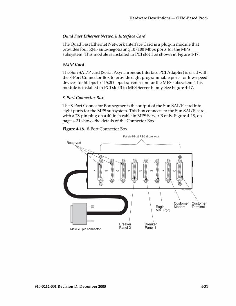
Hardware Descriptions — OEM-Based Prod-
910-0212-001 Revision D, December 2005 4-31
Quad Fast Ethernet Network Interface Card
The Quad Fast Ethernet Network Interface Card is a plug-in module that provides four RJ45 auto-negotiating 10/100 Mbps ports for the MPS subsystem. This module is installed in PCI slot 1 as shown in Figure 4-17.
SAI/P Card
The Sun SAI/P card (Serial Asynchronous Interface PCI Adapter) is used with the 8-Port Connector Box to provide eight programmable ports for low-speed devices for 50 bps to 115,200 bps transmission for the MPS subsystem. This module is installed in PCI slot 3 in MPS Server B only. See Figure 4-17.
8-Port Connector Box
The 8-Port Connector Box segments the output of the Sun SAI/P card into eight ports for the MPS subsystem. This box connects to the Sun SAI/P card with a 78-pin plug on a 40-inch cable in MPS Server B only. Figure 4-18, on page 4-31 shows the details of the Connector Box.
Figure 4-18. 8-Port Connector Box
DB25 Connectors 8
01234567
Male 78 pin connector
Female DB-25 RS-232 connector
CustomerTerminal
CustomerModem
BreakerPanel 1
BreakerPanel 2
,���$)�
EagleMMI Port

4-32 910-0212-001 Revision D, December 2005
Hardware Descriptions — OEM-Based Products
LEDs
The LEDs on the front of the MPS Server indicate the current status of the Netra t 1400 server. See Figure 4-19 for a view of the server front LEDs.
The System, Alarm, and Fault LEDs can also be forced on or off by a Lights Out Management (LOM) command. For details, refer to the Sun Netra t 1400/1405 Installation and User Guide.
Figure 4-19. Netra t 1400 Server LEDs
Table 4-5 describes the LEDs on the front of the MPS Server.
Table 4-5. Server LEDs
LED Color Description
FAULT Amber Lights continuously when syscheck locates a critical failure
ALARM 1 Amber Lights continuously when syscheck locates a major failure
ALARM 2 Amber Lights continuously when syscheck locates a minor failure
SUPPLY A Green Lights whenever DC input A is present on all fitted PSUs
SUPPLY B Green Lights whenever DC input B is present on all fitted PSUs
POWER Green Lights at all times when the system is on
SYSTEM Green Off (or reset) during power up proceduresLights whenever UNIX is running and the alarms driver is installed
�� !"
�!����
�!����
� ##!$�� � ##!$�%
#&'( �$�"(�
�"%$
&�

Hardware Descriptions — OEM-Based Prod-
910-0212-001 Revision D, December 2005 4-33
AXi Servers
The following section describes the components of the AXi Release 1.0 servers.
NOTE: In this manual and in the associated Graphical User Interface (GUI) screens of the AXi applications the terms server and host are used interchangeably to describe the Sun Netra t 1400 servers.
AXi servers are configured using Sun Netra t 1400 servers that are designated by the application or functions they are providing. In AXi Release 1.0 systems the following functional server types are used:
• Application Servers (AS) - Support the signaling interface between the end-user telephony devices and other servers and network devices. AS support a small computer system interface (SCSI) bus connecting to a Sun systems RAID array. All AS are configured with an adjunct RAID array disk system with paired, mirrored disks for data redundancy and reliability.
• Media Servers (MS) - Provide media resources such as digit collection, voice messaging and media mixing functions (for example conferencing). MS are controlled by AS using a proprietary media control protocol (MCP).
• Network Servers (NS) - Provide network services including translations and routing and enterprise applications such as Virtual Private Networks (VPN). NS communicates with AS or other network devices using the Session Initiation protocol (SIP).
AXi Release 1.0 servers are two- or four-processor devices that use the family of Sun UltraSPARC™ II processors. The AXi server provides the following:
• High performance processors
• Extensive I/O expansion and a wide range of options
• Modular internal design
• High performance disk, system, memory and I/O subsystems
• High performance peripheral component interconnect (PCI) I/O
• Redundant hot swap power supply units
• Alarm functionality for remote management
• Powered by redundant –48VDC supplies

4-34 910-0212-001 Revision D, December 2005
Hardware Descriptions — OEM-Based Products
AXi Server Features
The Sun Netra t 1400 primary board contains the CPU module, memory, system control application-specific integrated circuits (ASIC) and I/O ASICs. The following table lists the AXi Server specifications and specific configuration differences for the functional server types used in the AXi systems.
Table 4-6. AXi Server Specifications
Dimensions and Weight Height Width Depth Weight (unpackaged but fully configured)
264 mm (10.4 inches/6U) 431.8 mm (17 inches) 504.7 mm (19.9 inches)
37 kg (81.8 lbs.)
CPU Processor type Clock rate CPUs provided
Cache on module
UltraSPARC-II 64-bit processor 440 MHz Two or Four UltraSPARC-II processors(NEBS level 3 compliant) 4 MB Ecache
Memory Size Memory type
Two or four Gbyte ECC
Storage (Internal) Bus SCSI disks
DVD-ROMTape drive
40 MB/second UltraSCSI Two 36.4 GB 10K-rpm disks per server (On Application Servers, the disks are configured for mirrored operation)
DDS-3, 12-24 GB, 4 mm (Used on Application Servers and Network Servers)
I/O ArchitecturePCI QFE Interface Serial Asynchronous PCI interface cardSerial ports Parallel port SCSI
Four 100/10BASE-T ports (installed in slot 1)Additional Serial interface only used in the first Network Server NS A (Installed in slot 2)Two asynch (76.8 Kb)/synch (64 Kb) DB25External Fast-20 (UltraSCSI) 68-pin port (Used only in Application Servers (AS) requires adapter Sun part number X6541A)
Operating Environment Solaris 8.0

Hardware Descriptions — OEM-Based Prod-
910-0212-001 Revision D, December 2005 4-35
AXi Server Components
DVD-ROM
The DVD-ROM drive is a read-only random access device located on the front of the AXi server, below the DDS-3 Tape Drive. The DVD-ROM drive can function as a CD-ROM. The locations of the DVD-ROM, server power switch, and system LEDs are shown in Figure 4-20, on page 4-36.
Tape Drive (AS and NS Only)
The DDS-3 Tape Drive is a 4mm drive located on the front of the server above the DVD-ROM. The tape drive has 12 GB of memory in native mode and 24 GB compressed. The location of the tape drive is shown in Figure 4-20, on page 4-36.
The Tape Drive has two indicator lights, “Activity” and “Attention.” The activity light flashes green to show activity and remains solid green in the ready or standby mode. The attention light flashes amber to indicate the cartridge is near end of life or the head needs cleaning. The attention light turns steady amber to indicate a hard fault requiring drive replacement. For additional details refer to Sun 12-24 Gbyte 4mm DDS-3 Tape Drive Installation and User’s Guide, “Panel Descriptions.”
Quad Fast Ethernet Network Interface Card
The Quad FastEthernet Network Interface Card is a plug-in module that provides four RJ45 auto-negotiating 10/100 Mbps ports for the AXi subsystem. This module is installed in PCI slot 1 as shown in Figure 4-21, on page 4-37.
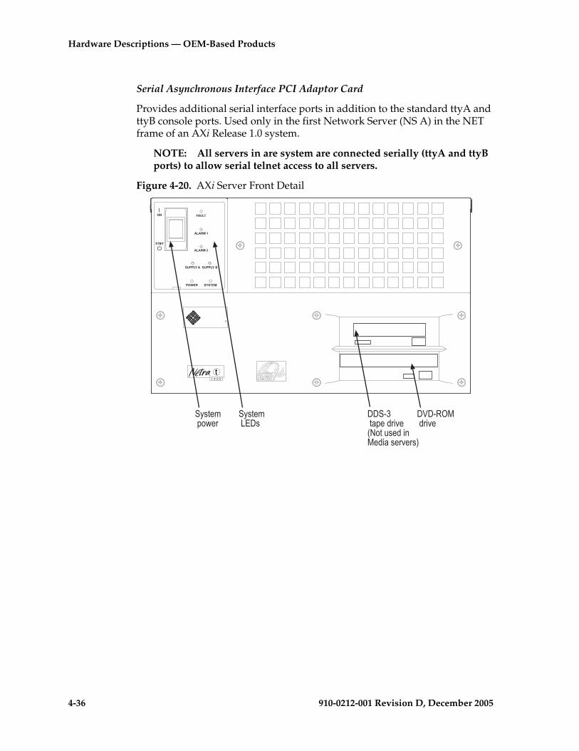
4-36 910-0212-001 Revision D, December 2005
Hardware Descriptions — OEM-Based Products
Serial Asynchronous Interface PCI Adaptor Card
Provides additional serial interface ports in addition to the standard ttyA and ttyB console ports. Used only in the first Network Server (NS A) in the NET frame of an AXi Release 1.0 system.
NOTE: All servers in are system are connected serially (ttyA and ttyB ports) to allow serial telnet access to all servers.
Figure 4-20. AXi Server Front Detail
�������
����������
������� ���
����������������������������������������
�������������
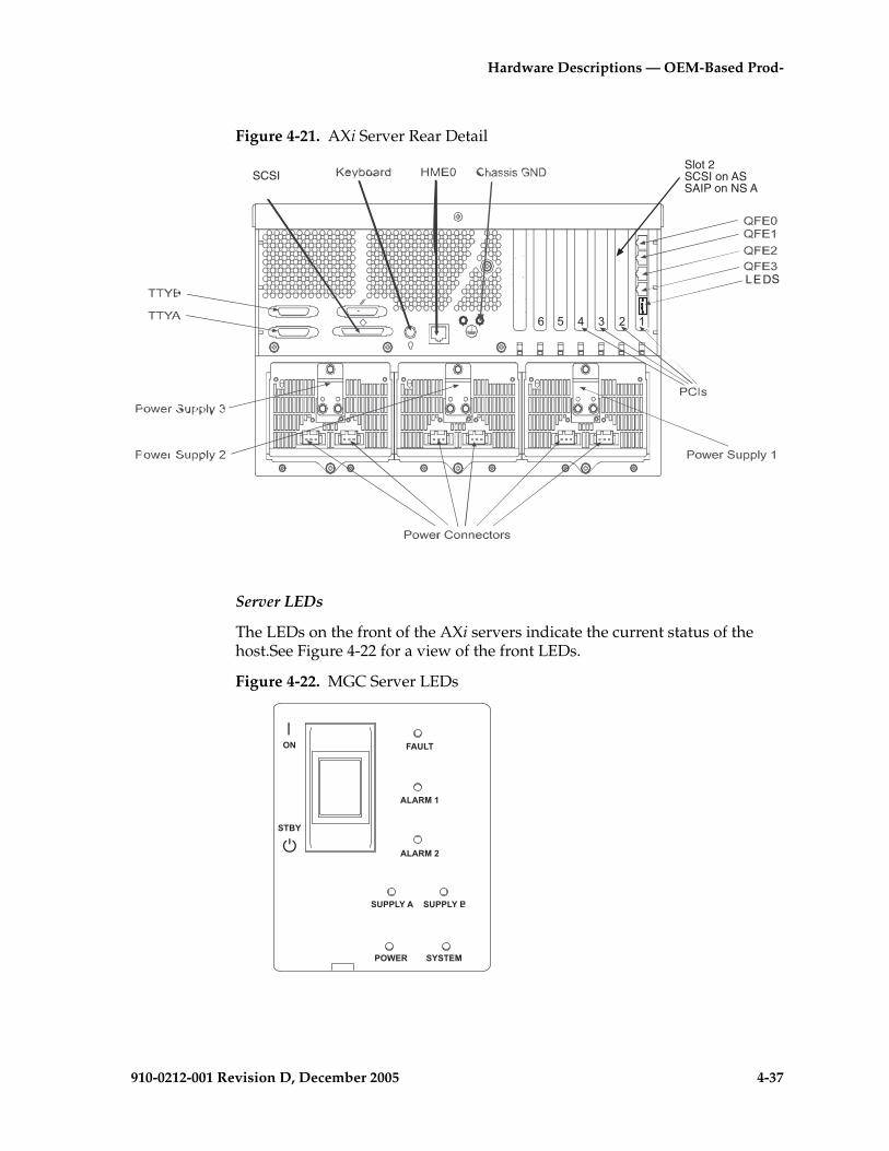
Hardware Descriptions — OEM-Based Prod-
910-0212-001 Revision D, December 2005 4-37
Figure 4-21. AXi Server Rear Detail
Server LEDs
The LEDs on the front of the AXi servers indicate the current status of the host.See Figure 4-22 for a view of the front LEDs.
Figure 4-22. MGC Server LEDs
�����
LEDS
SCSISlot 2SCSI on ASSAIP on NS A
�� !"
�!����
�!����
� ##!$�� � ##!$�%
#&'( �$�"(�
�"%$
&�

4-38 910-0212-001 Revision D, December 2005
Hardware Descriptions — OEM-Based Products
Table 4-7 describes the LED indicators on the front and rear of the server.
Eight-Port Connector Box
The Eight-Port Connector Box segments the output of the Sun SAI/P card in slot two of NS A into eight ports for the AXi subsystem. Figure 4-25 shows the details of the Connector Box.
Table 4-7. AXi Server LEDs
LED Color Description
FAULT Amber Blinks when a fan or Power Supply Unit (PSU) has failedLights continuously when manually switched on
ALARM 1 Amber Illuminated when the AXi server critical alarms are present
ALARM 2 Amber Illuminated when the AXi server major alarms are present
SUPPLY A Green Lights whenever DC input A is present on all fitted PSUs
SUPPLY B Green Lights whenever DC input B is present on all fitted PSUs
POWER Green Lights at all times when the system is on
SYSTEM Green Off (or reset) during power up proceduresLights when UNIX is running and the alarms driver is installedNote: This LED is reset by a hardware watchdog timeout or whenever the user-defined Alarm 3 is asserted
LINK Green Located on Quad Fast Ethernet card in slot 1 at the rear of the server. LED indicators from top to bottom correspond to QFE0 to QFE3. Lights when links are connected.
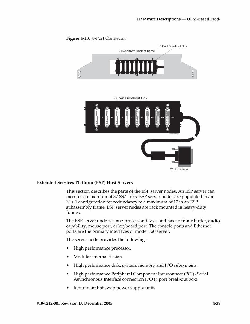
Hardware Descriptions — OEM-Based Prod-
910-0212-001 Revision D, December 2005 4-39
Figure 4-23. 8-Port Connector
Extended Services Platform (ESP) Host Servers
This section describes the parts of the ESP server nodes. An ESP server can monitor a maximum of 32 SS7 links. ESP server nodes are populated in an N + 1 configuration for redundancy to a maximum of 17 in an ESP subassembly frame. ESP server nodes are rack mounted in heavy-duty frames.
The ESP server node is a one-processor device and has no frame buffer, audio capability, mouse port, or keyboard port. The console ports and Ethernet ports are the primary interfaces of model 120 server.
The server node provides the following:
• High performance processor.
• Modular internal design.
• High performance disk, system, memory and I/O subsystems.
• High performance Peripheral Component Interconnect (PCI)/Serial Asynchronous Interface connection I/O (8 port break-out box).
• Redundant hot swap power supply units.
Viewed from back of frame
8 Port Breakout Box
sentinel breakout box
78 pin connector
8 Port Breakout Box
4-40 910-0212-001 Revision D, December 2005
Hardware Descriptions — OEM-Based Products
• Powered by redundant –48VDC supplies.
Server Model 120 Features
The server primary board contains the Central Processing Unit (CPU) module, memory, system control Application-Specific Integrated Circuits (ASICs) and I/O ASICs.
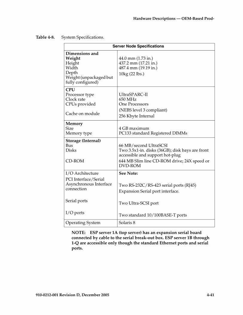
Hardware Descriptions — OEM-Based Prod-
910-0212-001 Revision D, December 2005 4-41
Table 4-8. System Specifications.
NOTE: ESP server 1A (top server) has an expansion serial board connected by cable to the serial break-out box. ESP server 1B through 1-Q are accessible only though the standard Ethernet ports and serial ports.
Server Node Specifications
Dimensions and WeightHeight Width Depth Weight (unpackaged but fully configured)
44.0 mm (1.73 in.) 437.2 mm (17.21 in.)487.4 mm (19.19 in.)10kg (22 lbs.)
CPUProcessor type Clock rate CPUs provided
Cache on module
UltraSPARC-II650 MHzOne Processors(NEBS level 3 compliant) 256 Kbyte Internal
MemorySize Memory type
4 GB maximumPC133 standard Registered DIMMs
Storage (Internal) Bus Disks
CD-ROM
66 MB/second UltraSCSI Two 3.5x1-in. disks (36GB); disk bays are front accessible and support hot-plug 644 MB Slim line CD-ROM drive; 24X speed or DVD-ROM
I/O ArchitecturePCI Interface/Serial Asynchronous Interface connection
Serial ports
I/O ports
See Note:
Two RS-232C/RS-423 serial ports (RJ45) Expansion Serial port interface.
Two Ultra-SCSI port
Two standard 10/100BASE-T ports
Operating System Solaris 8
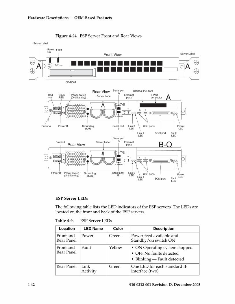
4-42 910-0212-001 Revision D, December 2005
Hardware Descriptions — OEM-Based Products
Figure 4-24. ESP Server Front and Rear Views
ESP Server LEDs
The following table lists the LED indicators of the ESP servers. The LEDs are located on the front and back of the ESP servers.
Power ARear View
1
Power switch(ON/Standby)
Groundingstuds
Serial port A
Serial port B
0 1
Ethernetports
Link 0LED
Link 1LED
USB ports
SCSI port FaultLED
PowerLED
Power B
B-QServer Label
Power A
Rear View
1
Power switch(ON/Standby)
Groundingstuds
Serial port A
Serial port B
0 1
Ethernetports
Link 0LED
Link 1LED
USB ports
SCSI port FaultLED
PowerLED
Optional PCI card
Power B
A8 Portconnector
A LOM
B SERIAL
Server Label
1 2 3
Red-48
BlackRTN
Front View
CD-ROM
PowerOn
Fault
sentinel server
A A
Server Label
Server Label
A LOM
B SERIAL
#
A0 1
0 1
Table 4-9. ESP Server LEDs
Location LED Name Color Description
Front and Rear Panel
Power Green Power feed available and Standby/on switch ON
Front and Rear Panel
Fault Yellow • ON Operating system stopped• OFF No faults detected• Blinking — Fault detected
Rear Panel Link Activity
Green One LED for each standard IP interface (two)
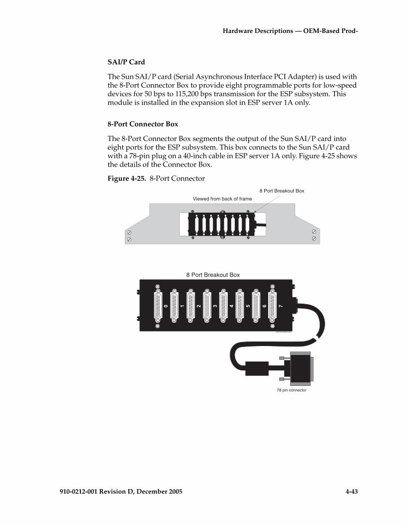
Hardware Descriptions — OEM-Based Prod-
910-0212-001 Revision D, December 2005 4-43
SAI/P Card
The Sun SAI/P card (Serial Asynchronous Interface PCI Adapter) is used with the 8-Port Connector Box to provide eight programmable ports for low-speed devices for 50 bps to 115,200 bps transmission for the ESP subsystem. This module is installed in the expansion slot in ESP server 1A only.
8-Port Connector Box
The 8-Port Connector Box segments the output of the Sun SAI/P card into eight ports for the ESP subsystem. This box connects to the Sun SAI/P card with a 78-pin plug on a 40-inch cable in ESP server 1A only. Figure 4-25 shows the details of the Connector Box.
Figure 4-25. 8-Port Connector
Viewed from back of frame
8 Port Breakout Box
sentinel breakout box
78 pin connector
8 Port Breakout Box

4-44 910-0212-001 Revision D, December 2005
Hardware Descriptions — OEM-Based Products
IP7 Front End (Optional)
The optional IP7 Front End is mounted in top shelf in the frame. Two to twelve SS7 link Interface Modules (LIM) can be configured for accessing the telephony network. Two Data Communication Module (DCM) cards provide two 10/100Base-T links to the internal LAN. Table 4-10, lists the interconnecting cables of the IP7 Front End.
Table 4-10. IP7 Front End Connections
From To Part Number description
Backplane ports 1A/1B through 9A/ 9B
Customer supplied DSX Block
Customer supplied
DB26 to un-terminated use selectable due to variety of LIM cards available
IMT A Out J22 IMT A IN J23 830-0221-04 Coax loopback from IMT A Out to IMT A in
IMT B Out J74 IMT B IN J75 830-0221-04 Coax loopback from IMT B Out to IMT B in
Backplane Row Alarm
End Panel Alarm
830-0232-01 End Panel Alarm Lights from IP7 Front End shelf
MMI0 MMI15 ports
MMI Devices 850-0535-xx xx implies length choice
BITs Clocks Composite Clocks
830-0727-xx xx implies length choice
Port 3A J43 Hub B, port 14
830-0788-01 10/100 Base-T from DCM card to DB26/RJ-45 Hub connection
Port 1A J45 Hub A, port 14
830-0788-01 10/100 Base-T from DCM card to DB26/RJ-45 Hub
Local Maintenance Center (LMC) J47
Customer Supplied Maintenance Block
830-0231-xx Dry Relay Alarm Contacts
Remote Maintenance Center (RMC) J33
Customer Supplied Maintenance Block
830-0233-xx Dry Relay Alarm Contacts
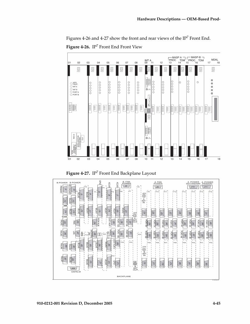
Hardware Descriptions — OEM-Based Prod-
910-0212-001 Revision D, December 2005 4-45
Figures 4-26 and 4-27 show the front and rear views of the IP7 Front End.
Figure 4-26. IP7 Front End Front View
Figure 4-27. IP7 Front End Backplane Layout
IMT A
10
01 02 03 04 05 06 07 08 09 11 12 13 14 15 16 17 18
01 02 03 04 05 06 07 08 11 12 13 14 15 16 17 18
TDMTDM MDALPROC PROCMASP A MASP-B
0 1
2 3
4 5
6 7
8 9
01
23
45
67
89
RE
V X
IPM
X870-1
171-X
X
5VALARM
0 1
2 3
4 5
6 7
8 9
0123
4567
89
5VALARM
TEKELEC
TEKELEC TEKELEC TEKELEC TEKELEC TEKELEC TEKELEC TEKELEC TEKELECTEKELEC TEKELEC TEKELEC TEKELEC TEKELEC TEKELEC TEKELEC0
1 2
3 4
5 6
7 8
9
0123
4567
89
DC
MA
SS
EM
BLY
012-
3456
-78
APPLPROC
IMT A
IMT B
PORT A
PORT B
CLI
I
SE
RIL
AZ
AT
ION
0123
4567
890RE
V-X
�� ��
�� ��
��
� �
�� �? ��� ������
���
���
���
��
��
���
��?
��� ���
���
���
���
��� ��
��
���
��?
���
���
���
��� ���
���
��
�� ���
��?
���
���
���
���
���
���
��
�� ���
��? ���
��� ���
���
���
���
��
��
���
��?
�� ��
��
��
��
�
� ��
�?
�� ��
�� ��
��
��
� � ��
�?
���
���
��� ���
. ��0�,�,��.,;
*� 7��2('�!�
. ��0�,��+���.,;����0�, ����0�,
�.+>��.��
.��-��
.��-�/-
.+�>
.+�>�
,.��
,.���
�.�.��
8���
���-��
���-�/-
.+�>�
�+�>�
+/�-.��
�
+/�-.��
�
����.����0�,
.���.���0�,
�$�%�$9
����
���"! �$9����,��
���������������������?
��
����
��
��
��
��
�����������?����������
���
������
���
��?
���
��
���
,�0.��
,.��
,.���
,.���
��+
,�+
,.���
,.���
�,��.,;
��+���.,;,.��
�
�+�>�
�+�>
.+�>
.+�>�.+�>�
.+�>�
.+�>�
��
�+�>�
��,-��
��,-��
��,-��
��,-��
��,-��
��,-�
��,-�
��,-��
��,-�.
��,-
�.
��,-�.
��,-�.
��,-�.
��,-.
��,-
.
��,-�.
��,-?�
��,-���
��,-?.
��,-��.
8���
�+�>�
�+�>
�+�>�
�+�>�
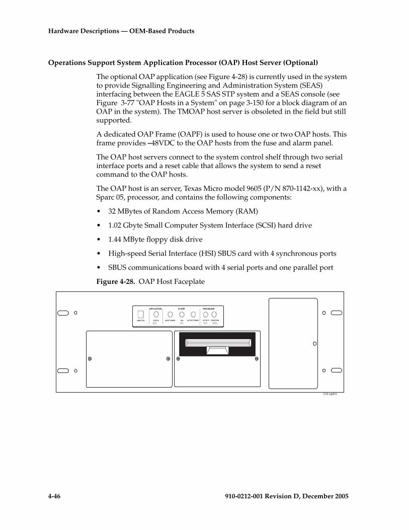
4-46 910-0212-001 Revision D, December 2005
Hardware Descriptions — OEM-Based Products
Operations Support System Application Processor (OAP) Host Server (Optional)
The optional OAP application (see Figure 4-28) is currently used in the system to provide Signalling Engineering and Administration System (SEAS) interfacing between the EAGLE 5 SAS STP system and a SEAS console (see Figure 3-77 "OAP Hosts in a System" on page 3-150 for a block diagram of an OAP in the system). The TMOAP host server is obsoleted in the field but still supported.
A dedicated OAP Frame (OAPF) is used to house one or two OAP hosts. This frame provides –48VDC to the OAP hosts from the fuse and alarm panel.
The OAP host servers connect to the system control shelf through two serial interface ports and a reset cable that allows the system to send a reset command to the OAP hosts.
The OAP host is an server, Texas Micro model 9605 (P/N 870-1142-xx), with a Sparc 05, processor, and contains the following components:
• 32 MBytes of Random Access Memory (RAM)
• 1.02 Gbyte Small Computer System Interface (SCSI) hard drive
• 1.44 MByte floppy disk drive
• High-speed Serial Interface (HSI) SBUS card with 4 synchronous ports
• SBUS communications board with 4 serial ports and one parallel port
Figure 4-28. OAP Host Faceplate
���������/ ����� ��������
��������� ������ �/������2�� 1�/ ���������2�� ������0 �/�����/�%��>�,������
�%��>�,������
�%��>�,������
)���6$(��'�%��>�
�������,���
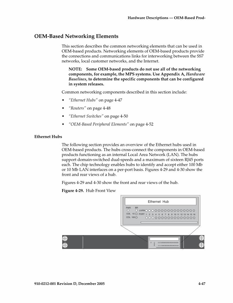
Hardware Descriptions — OEM-Based Prod-
910-0212-001 Revision D, December 2005 4-47
OEM-Based Networking Elements
This section describes the common networking elements that can be used in OEM-based products. Networking elements of OEM-based products provide the connections and communications links for interworking between the SS7 networks, local customer networks, and the Internet.
NOTE: Some OEM-based products do not use all of the networking components, for example, the MPS systems. Use Appendix A, Hardware Baselines, to determine the specific components that can be configured in system releases.
Common networking components described in this section include:
• “Ethernet Hubs” on page 4-47
• “Routers” on page 4-48
• “Ethernet Switches” on page 4-50
• “OEM-Based Peripheral Elements” on page 4-52
Ethernet Hubs
The following section provides an overview of the Ethernet hubs used in OEM-based products. The hubs cross-connect the components in OEM-based products functioning as an internal Local Area Network (LAN). The hubs support domain-switched dual-speeds and a maximum of sixteen RJ45 ports each. The chip technology enables hubs to identify and accept either 100 Mb or 10 Mb LAN interfaces on a per-port basis. Figures 4-29 and 4-30 show the front and rear views of a hub.
Figures 4-29 and 4-30 show the front and rear views of the hub.
Figure 4-29. Hub Front View
1 2 3 4 5 6 7 8 9 10 11 12 13 14 15 16
PWR BR
COL 10
COL 100
LX/RX
PORT
Ethernet Hub
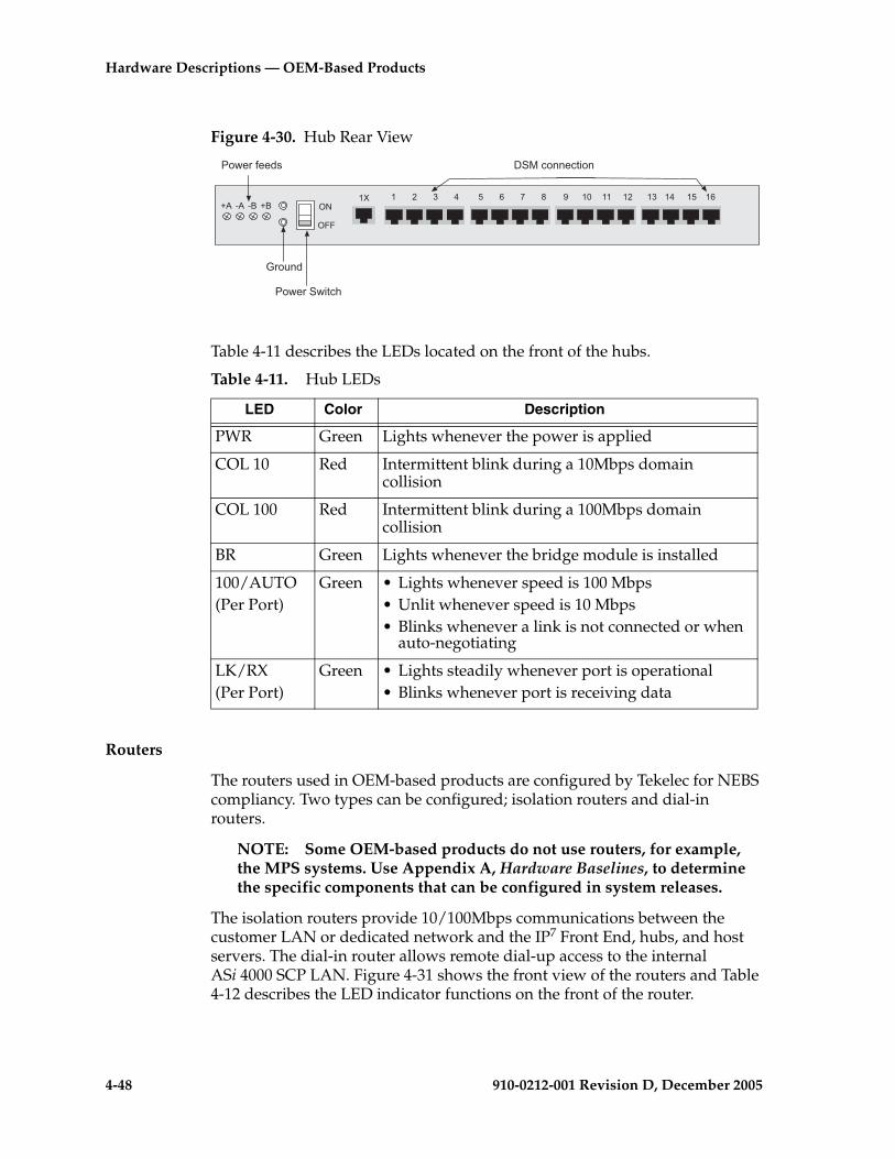
4-48 910-0212-001 Revision D, December 2005
Hardware Descriptions — OEM-Based Products
Figure 4-30. Hub Rear View
Table 4-11 describes the LEDs located on the front of the hubs.
Routers
The routers used in OEM-based products are configured by Tekelec for NEBS compliancy. Two types can be configured; isolation routers and dial-in routers.
NOTE: Some OEM-based products do not use routers, for example, the MPS systems. Use Appendix A, Hardware Baselines, to determine the specific components that can be configured in system releases.
The isolation routers provide 10/100Mbps communications between the customer LAN or dedicated network and the IP7 Front End, hubs, and host servers. The dial-in router allows remote dial-up access to the internal ASi 4000 SCP LAN. Figure 4-31 shows the front view of the routers and Table 4-12 describes the LED indicator functions on the front of the router.
Table 4-11. Hub LEDs
LED Color Description
PWR Green Lights whenever the power is applied
COL 10 Red Intermittent blink during a 10Mbps domain collision
COL 100 Red Intermittent blink during a 100Mbps domain collision
BR Green Lights whenever the bridge module is installed
100/AUTO(Per Port)
Green • Lights whenever speed is 100 Mbps• Unlit whenever speed is 10 Mbps• Blinks whenever a link is not connected or when
auto-negotiating
LK/RX(Per Port)
Green • Lights steadily whenever port is operational• Blinks whenever port is receiving data
4� %����%����
3����6
��#��,��6)
�� �� �� �� �� ��� � � � � � � � � ��2.
211
@ � �! @!
��#���#��%�
�

Hardware Descriptions — OEM-Based Prod-
910-0212-001 Revision D, December 2005 4-49
Figure 4-31. Front View Routers
Figures 4-32 and 4-33 show rear views of the Isolation and Dial-In routers. Link (LNK) and activity (ACT) LEDs are located near each ethernet port at the rear of the routers. Table 4-13 describes the LED indicators on the rear of the routers.
Figure 4-32. Rear View Isolation Router
Figure 4-33. Rear View Dial-in Router
Cisco 2600 SERIES
POWER RPS ACTIVITY
cisco router
Table 4-12. Router Front LEDs
LED Description
PWR Indicates when power is present to the router and the power switch is in the ON position.
RPS(Always OFF)
Off when the redundant power supply is not present.On redundant power supply is present and functional.
Activity Off-No network activityBlink-Network activity
Table 4-13. Router Rear LEDs
LED Description
LNK Indicates link is established to far end connection.
ACT Blink-indicates data activity on the link.
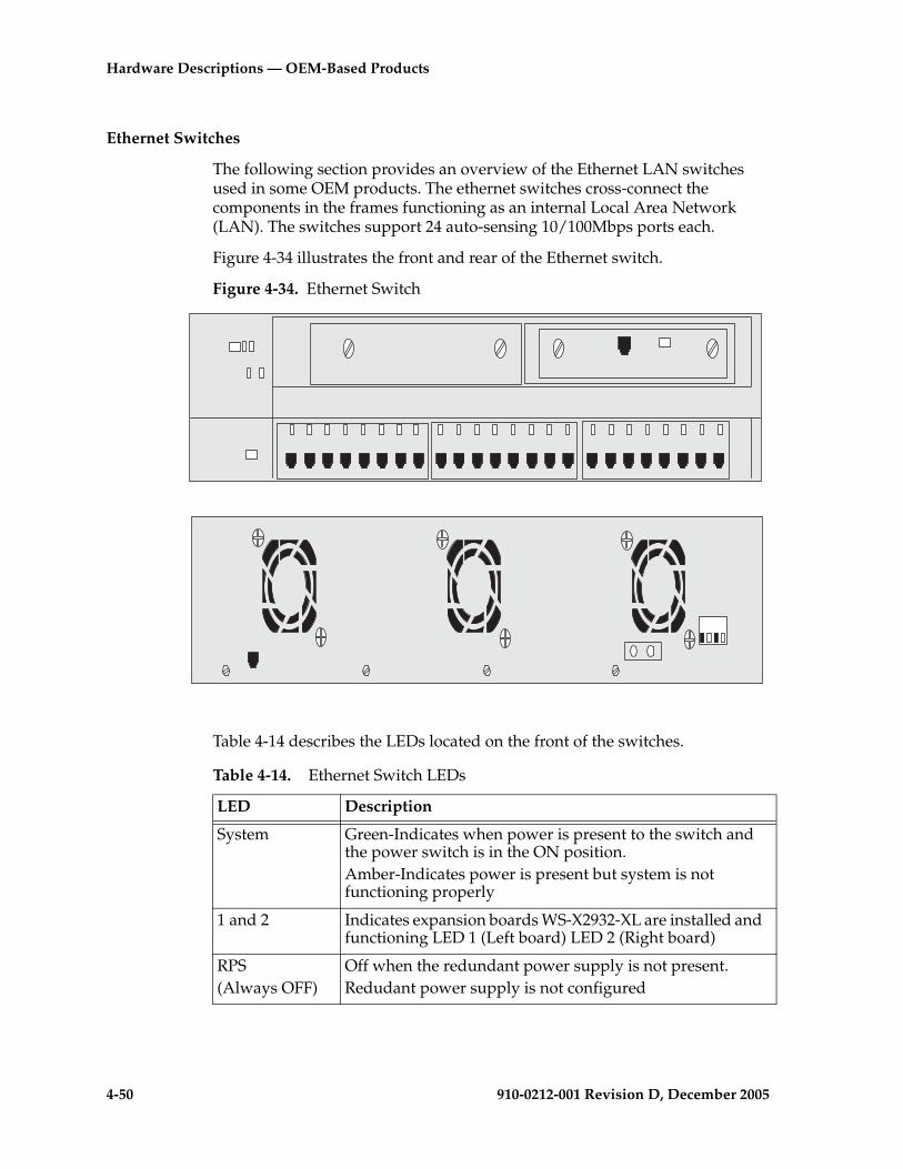
4-50 910-0212-001 Revision D, December 2005
Hardware Descriptions — OEM-Based Products
Ethernet Switches
The following section provides an overview of the Ethernet LAN switches used in some OEM products. The ethernet switches cross-connect the components in the frames functioning as an internal Local Area Network (LAN). The switches support 24 auto-sensing 10/100Mbps ports each.
Figure 4-34 illustrates the front and rear of the Ethernet switch.
Figure 4-34. Ethernet Switch
Table 4-14 describes the LEDs located on the front of the switches.
Table 4-14. Ethernet Switch LEDs
LED Description
System Green-Indicates when power is present to the switch and the power switch is in the ON position.Amber-Indicates power is present but system is not functioning properly
1 and 2 Indicates expansion boards WS-X2932-XL are installed and functioning LED 1 (Left board) LED 2 (Right board)
RPS(Always OFF)
Off when the redundant power supply is not present.Redudant power supply is not configured
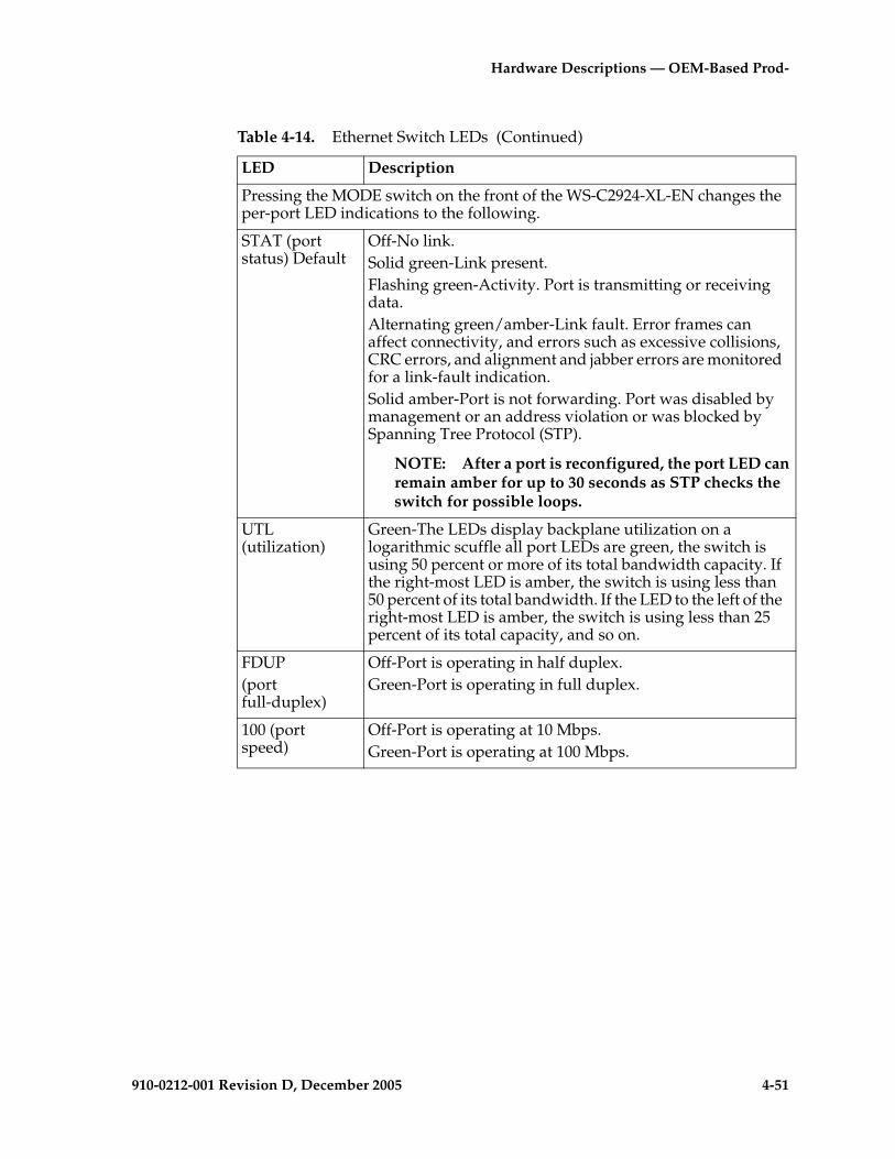
Hardware Descriptions — OEM-Based Prod-
910-0212-001 Revision D, December 2005 4-51
Pressing the MODE switch on the front of the WS-C2924-XL-EN changes the per-port LED indications to the following.
STAT (port status) Default
Off-No link.Solid green-Link present.Flashing green-Activity. Port is transmitting or receiving data.Alternating green/amber-Link fault. Error frames can affect connectivity, and errors such as excessive collisions, CRC errors, and alignment and jabber errors are monitored for a link-fault indication.Solid amber-Port is not forwarding. Port was disabled by management or an address violation or was blocked by Spanning Tree Protocol (STP).
NOTE: After a port is reconfigured, the port LED can remain amber for up to 30 seconds as STP checks the switch for possible loops.
UTL (utilization)
Green-The LEDs display backplane utilization on a logarithmic scuffle all port LEDs are green, the switch is using 50 percent or more of its total bandwidth capacity. If the right-most LED is amber, the switch is using less than 50 percent of its total bandwidth. If the LED to the left of the right-most LED is amber, the switch is using less than 25 percent of its total capacity, and so on.
FDUP (port full-duplex)
Off-Port is operating in half duplex.Green-Port is operating in full duplex.
100 (port speed)
Off-Port is operating at 10 Mbps.Green-Port is operating at 100 Mbps.
Table 4-14. Ethernet Switch LEDs (Continued)
LED Description
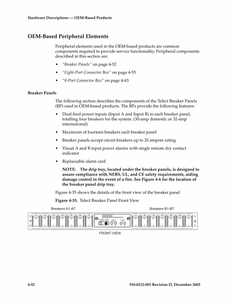
4-52 910-0212-001 Revision D, December 2005
Hardware Descriptions — OEM-Based Products
OEM-Based Peripheral Elements
Peripheral elements used in the OEM-based products are common components required to provide service functionality. Peripheral components described in this section are:
• “Breaker Panels” on page 4-52
• “Eight-Port Connector Box” on page 4-55
• “8-Port Connector Box” on page 4-43
Breaker Panels
The following section describes the components of the Telect Breaker Panels (BP) used in OEM-based products. The BPs provide the following features:
• Dual-feed power inputs (Input A and Input B) to each breaker panel, totalling four breakers for the system. (30-amp domestic or 32-amp international)
• Maximum of fourteen breakers each breaker panel
• Breaker panels accept circuit breakers up to 20 ampere rating
• Visual A and B input power alarms with single remote dry contact indicator
• Replaceable alarm card
NOTE: The drip tray, located under the breaker panels, is designed to assure compliance with NEBS, UL, and CE safety requirements, aiding damage control in the event of a fire. See Figure 4-6 for the location of the breaker panel drip tray.
Figure 4-35 shows the details of the front view of the breaker panel
Figure 4-35. Telect Breaker Panel Front View
�,�.>�,.�.,�
.�.,�,���- ���/-
�,�.>�,��0�,
��
. � . �
. �
�$��2�$��.�1. �$��2�$����1�
� � � � � � � � � �
�,��-�:��0
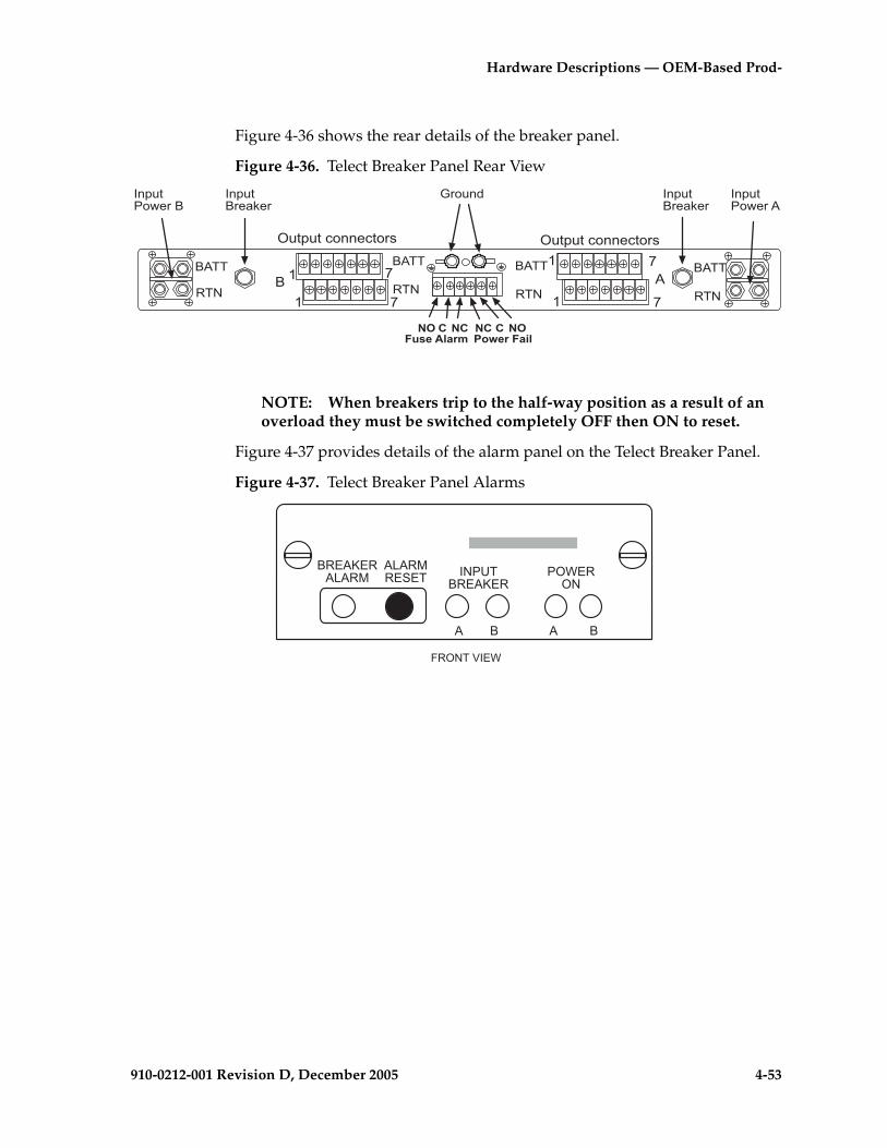
Hardware Descriptions — OEM-Based Prod-
910-0212-001 Revision D, December 2005 4-53
Figure 4-36 shows the rear details of the breaker panel.
Figure 4-36. Telect Breaker Panel Rear View
NOTE: When breakers trip to the half-way position as a result of an overload they must be switched completely OFF then ON to reset.
Figure 4-37 provides details of the alarm panel on the Telect Breaker Panel.
Figure 4-37. Telect Breaker Panel Alarms
� .�
�
�
�
�.--
�#�(#���"!!���"$� �#�(#���"!!���"$�
,-�
�.--
,-�
�.--
,-�
�.--
,-�
�!(#��$��2�$
�!(#��$��2�$
8$"#!
�& �)�*�����+�,
) �) �&#-.����+�
)
�!(#��"&�$�.
�!(#��"&�$��
�,��-�:��0
�,�.>�,.�.,�
.�.,�,���- ���/-
�,�.>�,��0�,
��
. � . �
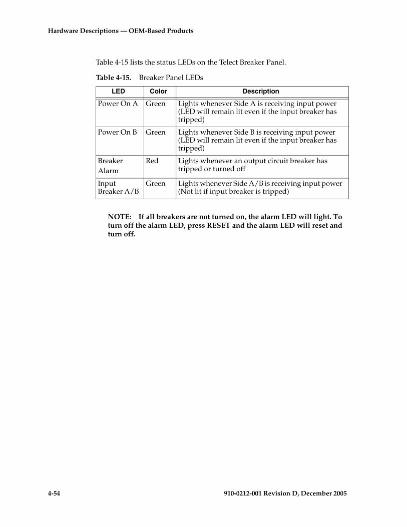
4-54 910-0212-001 Revision D, December 2005
Hardware Descriptions — OEM-Based Products
Table 4-15 lists the status LEDs on the Telect Breaker Panel.
NOTE: If all breakers are not turned on, the alarm LED will light. To turn off the alarm LED, press RESET and the alarm LED will reset and turn off.
Table 4-15. Breaker Panel LEDs
LED Color Description
Power On A Green Lights whenever Side A is receiving input power (LED will remain lit even if the input breaker has tripped)
Power On B Green Lights whenever Side B is receiving input power (LED will remain lit even if the input breaker has tripped)
BreakerAlarm
Red Lights whenever an output circuit breaker has tripped or turned off
Input Breaker A/B
Green Lights whenever Side A/B is receiving input power (Not lit if input breaker is tripped)
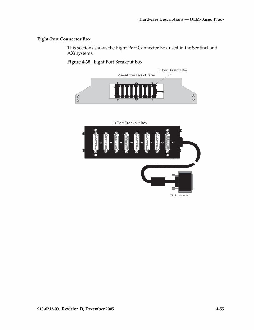
Hardware Descriptions — OEM-Based Prod-
910-0212-001 Revision D, December 2005 4-55
Eight-Port Connector Box
This sections shows the Eight-Port Connector Box used in the Sentinel and AXi systems.
Figure 4-38. Eight Port Breakout Box
Viewed from back of frame
8 Port Breakout Box
sentinel breakout box
78 pin connector
8 Port Breakout Box

4-56 910-0212-001 Revision D, December 2005
Hardware Descriptions — OEM-Based Products
910-0212-001 Revision D, December 2005 5-1
5
Hardware Descriptions —Sentinel Products
Sentinel Product Descriptions Overview .....................................................5–3
Sentinel Frames..........................................................................................5–4
Site Collector Frames ................................................................................5–6
Extended Services Platform (ESP)...........................................................5–7
Integrated Sentinel (probe-less Solution) .....................................................5–8
Integrated Sentinel Hardware Overview...............................................5–9
ESP Subsystem.........................................................................................5–15
ESP Subsystem Hardware Components ..............................................5–15
Sentinel Probe Based Site Collector .............................................................5–20
Site Collector Frames ..............................................................................5–22
Site Collector Frame Hardware Components .....................................5–24
Sentinel Central Server Frames....................................................................5–26
Sentinel Central Server Frame Hardware Components ....................5–28
Sentinel Central Server Frames Prior to Release 10.0.........................5–30
Sentinel Central Server Frames Release 10.0 .......................................5–32
Sentinel Frames Common Components .....................................................5–34
Breaker Panels..........................................................................................5–34
SAI/P Card...............................................................................................5–36
8-Port Break-Out Box ..............................................................................5–36
5-2 910-0212-001 Revision D, December 2005
Hardware Descriptions — Sentinel Products
Ethernet Interface Cards ........................................................................ 5–36
Ethernet Switches.................................................................................... 5–37
Routers...................................................................................................... 5–41
Hubs.......................................................................................................... 5–42
Console/Alarm Servers ......................................................................... 5–43

Hardware Descriptions — Sentinel Products
910-0212-001 Revision D, December 2005 5-3
Sentinel Product Descriptions Overview
This chapter documents Sentinel hardware products from Sentinel Release 8.1 and later. Sentinel products use some commercial off-the-shelf components and Tekelec proprietary products configured in heavy-duty frames.
Some of the hardware server components are based upon the Tekelec 1000 Applications Server (Tekelec 1000 APS) introduced with Sentinel Release 11.x. For information on Sentinel components that are based on the Tekelec 1000 platform, including assembly drawings, interconnect diagrams, and installation instructions, see the Tekelec 1000 Applications Server Hardware Manual.
A Sentinel system is comprised of two major system components: distributed site collectors located at remote sites and centralized servers located at the Network Operations Center (NOC). Site collectors are for remote deployments within a carrier's switching offices. For a probe-based configuration, one or more Probe and server systems are deployed at remote sites as site collectors. For the probe-less (Integrated) configuration, EAGLE STP and the ESP servers are the site collectors. Typically, Sentinel includes a Base System Server, Alarm Server and optional Traffic Database Server as well as one or more Data Gateway Servers in the NOC. User workstations are typically located either in the NOC or in a Technical Assistance Center (TAC). The Site Collectors are connected to the NOC via the customer WAN.
The Sentinel system can simultaneously support both probe-based and probe-less configurations. In a combined probe-based and probe-less configuration, the same NOC can be used to simultaneously monitor MSU data sent by an EAGLE STP or via the probes as shown in the Figure 5-1 on page 5-4.

5-4 910-0212-001 Revision D, December 2005
Hardware Descriptions — Sentinel Products
Figure 5-1. NOC in a Combined Probe-based and probe-less Configuration
Sentinel Frames
Sentinel systems are mounted in standard seven-foot high, 23-inch wide frames. Sentinel frames typically are configured with dual breaker panels and are cabled with redundant power busses for reliability. Sentinel products support application specific services that monitor SS7 network links. For information on unpacking and installation of Sentinel frames see the Installation Manual and Tekelec 1000 Applications Server Hardware Manual included in this documentation set.
The defined types of Sentinel Frame configurations include:
• Sentinel Servers (e.g. BSS, AS, DGS, TDS)
• i2000/FR Site Collector
• Flight Recorder
• Extended Services Platform (ESP)
WAN
ESP
Servers
LIM
EAGLE
STC
LAN
REMOTE SITE COLLECTORS NETWORK
Base
System
Server
Alarm
Server
Data
Gateway
Server
Traffic
Database
Server
(NOC) CENTRAL COLLECTORS
Probe
IMT
Server
ESP
Server
LAN
SS7 links
SS7 links
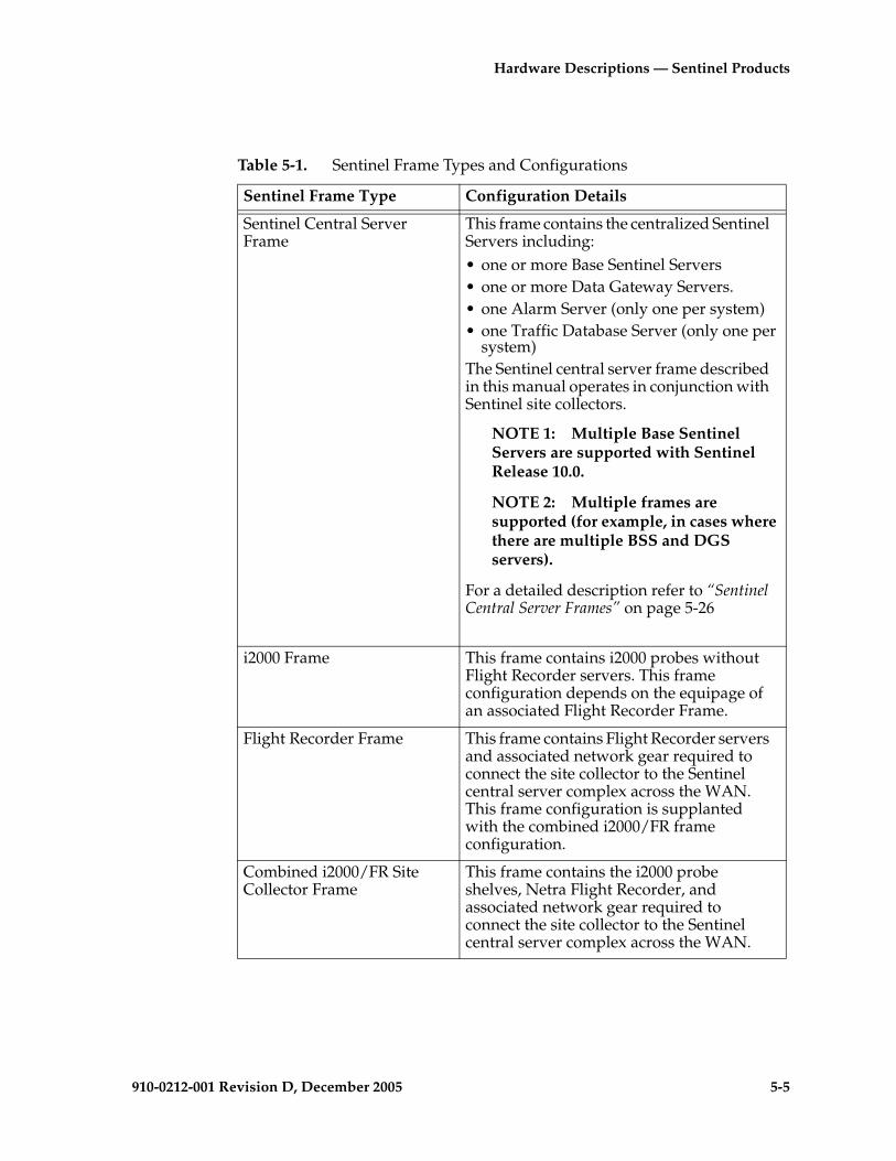
Hardware Descriptions — Sentinel Products
910-0212-001 Revision D, December 2005 5-5
Table 5-1. Sentinel Frame Types and Configurations
Sentinel Frame Type Configuration Details
Sentinel Central Server Frame
This frame contains the centralized Sentinel Servers including:• one or more Base Sentinel Servers• one or more Data Gateway Servers.• one Alarm Server (only one per system)• one Traffic Database Server (only one per
system)The Sentinel central server frame described in this manual operates in conjunction with Sentinel site collectors.
NOTE 1: Multiple Base Sentinel Servers are supported with Sentinel Release 10.0.
NOTE 2: Multiple frames are supported (for example, in cases where there are multiple BSS and DGS servers).
For a detailed description refer to “Sentinel Central Server Frames” on page 5-26
i2000 Frame This frame contains i2000 probes without Flight Recorder servers. This frame configuration depends on the equipage of an associated Flight Recorder Frame.
Flight Recorder Frame This frame contains Flight Recorder servers and associated network gear required to connect the site collector to the Sentinel central server complex across the WAN. This frame configuration is supplanted with the combined i2000/FR frame configuration.
Combined i2000/FR Site Collector Frame
This frame contains the i2000 probe shelves, Netra Flight Recorder, and associated network gear required to connect the site collector to the Sentinel central server complex across the WAN.
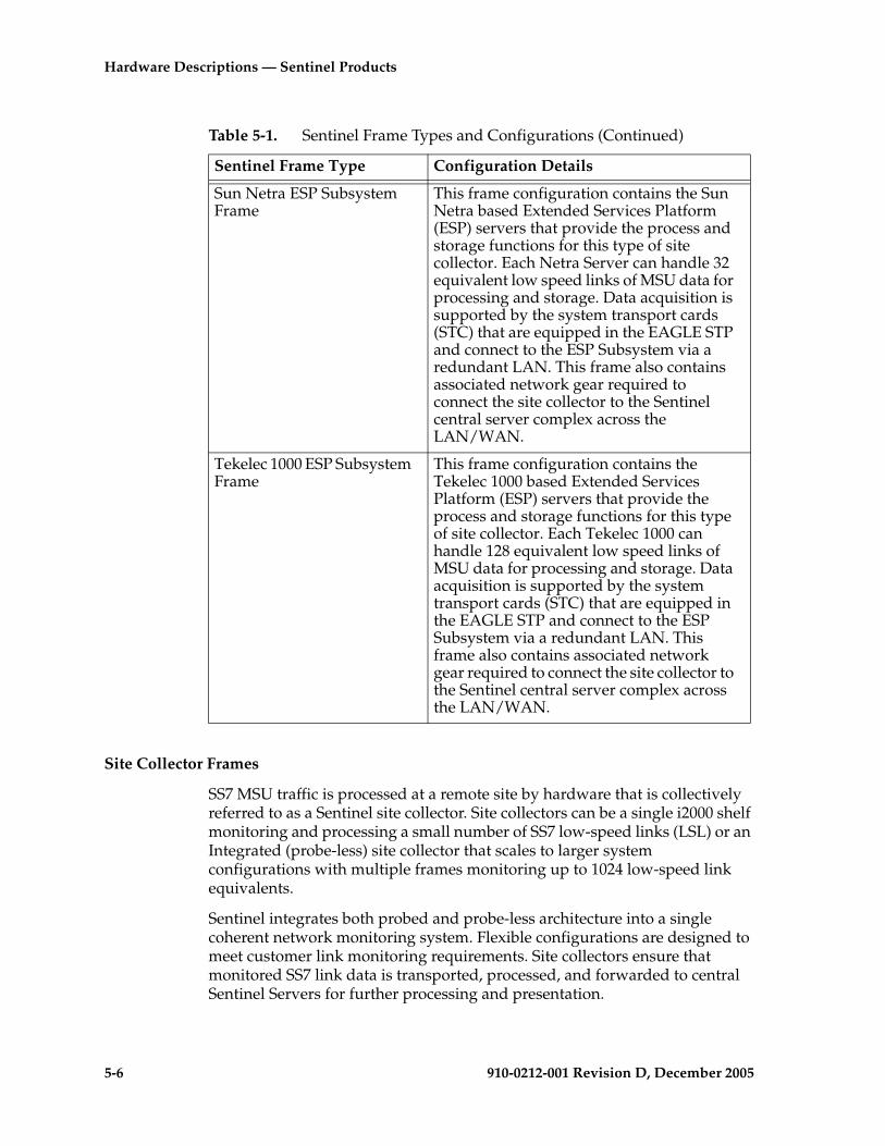
5-6 910-0212-001 Revision D, December 2005
Hardware Descriptions — Sentinel Products
Site Collector Frames
SS7 MSU traffic is processed at a remote site by hardware that is collectively referred to as a Sentinel site collector. Site collectors can be a single i2000 shelf monitoring and processing a small number of SS7 low-speed links (LSL) or an Integrated (probe-less) site collector that scales to larger system configurations with multiple frames monitoring up to 1024 low-speed link equivalents.
Sentinel integrates both probed and probe-less architecture into a single coherent network monitoring system. Flexible configurations are designed to meet customer link monitoring requirements. Site collectors ensure that monitored SS7 link data is transported, processed, and forwarded to central Sentinel Servers for further processing and presentation.
Sun Netra ESP Subsystem Frame
This frame configuration contains the Sun Netra based Extended Services Platform (ESP) servers that provide the process and storage functions for this type of site collector. Each Netra Server can handle 32 equivalent low speed links of MSU data for processing and storage. Data acquisition is supported by the system transport cards (STC) that are equipped in the EAGLE STP and connect to the ESP Subsystem via a redundant LAN. This frame also contains associated network gear required to connect the site collector to the Sentinel central server complex across the LAN/WAN.
Tekelec 1000 ESP Subsystem Frame
This frame configuration contains the Tekelec 1000 based Extended Services Platform (ESP) servers that provide the process and storage functions for this type of site collector. Each Tekelec 1000 can handle 128 equivalent low speed links of MSU data for processing and storage. Data acquisition is supported by the system transport cards (STC) that are equipped in the EAGLE STP and connect to the ESP Subsystem via a redundant LAN. This frame also contains associated network gear required to connect the site collector to the Sentinel central server complex across the LAN/WAN.
Table 5-1. Sentinel Frame Types and Configurations (Continued)
Sentinel Frame Type Configuration Details

Hardware Descriptions — Sentinel Products
910-0212-001 Revision D, December 2005 5-7
All Sentinel site collectors consist of the following three basic functional components:
• Data Acquisition - External probe-based connections to SS7 links using monitoring shelves (non-integrated solution) or internal connections to the EAGLE STP (integrated solution).
• LAN/WAN Transport - Connects all components of a Sentinel site collector, routers, ethernet switches, hubs, and servers.
• Processing and Storage - Site collector servers process monitored SS7 link information and message signalling units (MSU), storing data and forwarding to Base Sentinel Servers.
Flight Recorders
The Flight Recorder (FR) server provides the extended processing and storage server functions for a probe based site collector in conjunction with the i2000 probe shelf. The Flight Recorder server connects to one or more i2000 probe shelves via LAN to provide processing and storage. Refer to the section, “Sentinel Probe Based Site Collector” on page 5-20 for a complete description.
NOTE: See the Signaling/Cellular Generic Hardware Reference Manual (P/N 910-2277-01) for i2000 product information.
Extended Services Platform (ESP)
For the integrated (probe-less) site collector there are two different frame configurations; one with Sun Netra servers and the other with Tekelec 1000 servers. For a complete description of the Netra-based ESP frame refer to the section, “Integrated Sentinel (probe-less Solution)” on page 5-8. For Tekelec 1000-based Sentinel hardware, refer to the Tekelec 1000 Applications Server Hardware Manual. For additional information about EAGLE STP hardware components required for the Integrated Sentinel solution refer to the sections “Integrated Sentinel on the EAGLE 5 SAS STP Side” on page 2-22 and Chapter 3, Hardware Descriptions — EAGLE/IP7 SG-Based Products, of this manual.
5-8 910-0212-001 Revision D, December 2005
Hardware Descriptions — Sentinel Products
Integrated Sentinel (probe-less Solution)
The Integrated Sentinel feature with the Extended Services Platform (ESP) provides a probe-less site collector solution for monitoring EAGLE STP low-speed links and high-speed ATM links without using external probes. The feature eliminates the need for cabling and some hardware to monitor the EAGLE SS7 links. It also enables the EAGLE STP links to be presented in Integrated Sentinel in familiar terms as they are provisioned in the EAGLE. Link information is passed from the EAGLE STP to Sentinel via Sentinel Transport Cards (STC) in the EAGLE STP.

Hardware Descriptions — Sentinel Products
910-0212-001 Revision D, December 2005 5-9
Integrated Sentinel Hardware Overview
In Integrated Sentinel, site collector processing and storage tasks are hosted on ESP servers, providing all of the relevant site collector functions for data processing and storage of collected SS7 data. Integrated Sentinel ESP servers are connected to an associated EAGLE STP using redundant LAN interfaces. The internal local area network (LAN) traffic is isolated to keep monitored data separate from the customer’s wide area network (WAN).
The EAGLE STP monitors SS7 links internally (probe-less), at the LIM, and connects to ESP LAN interfaces using the dual-port Sentinel Transport Card (STC). The STC card acts as a router to route TCP/IP traffic from EAGLE STP ports to ESP servers.
Table 5-2. Sentinel Release Application Notes
Sentinel Release Note
Sentinel Release 9.0 The Sentinel Server Frame was introduced containing up to four Netra 20s configured as Sentinel servers. A Sentinel Server Frame can be configured with one to four servers to support: • Alarm Server • Base Sentinel Server • Data Gateway Server• Traffic Database ServerFor more information about Sentinel Server Frames see“Sentinel Central Server Frames” on page 5-26.
Sentinel Release 10.0 For Netra-based ESPs, a maximum of two ESP frames can be configured. A maximum of 1024 links can be monitored with two Netra-based ESP frames.Remote Dial-up access is configured in the first ESP frame with a Cisco modem card in the Yellow router.For remote access to Netra ESP servers in the ESP subsystem access is provided by the addition of a modem card to the yellow router. The NetGear RM356 Modem router is no longer configured in systems but is supported for older system configurations.For more information refer to “Netra-based ESP Frame Components Release 10.0” on page 5-15.
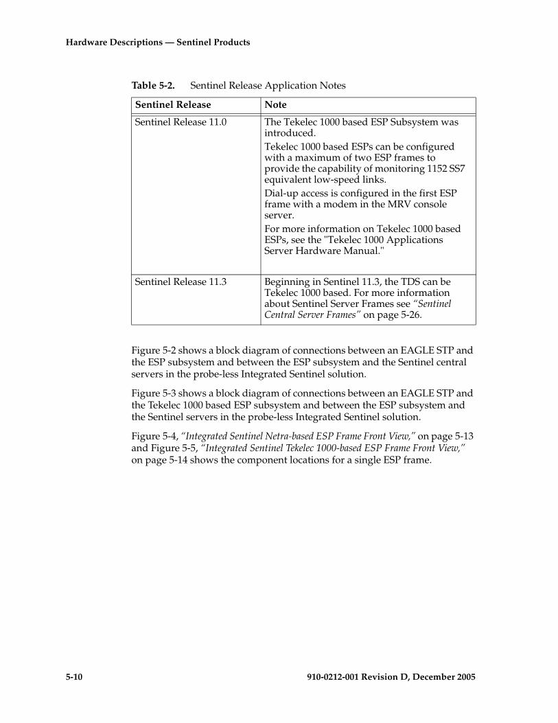
5-10 910-0212-001 Revision D, December 2005
Hardware Descriptions — Sentinel Products
Figure 5-2 shows a block diagram of connections between an EAGLE STP and the ESP subsystem and between the ESP subsystem and the Sentinel central servers in the probe-less Integrated Sentinel solution.
Figure 5-3 shows a block diagram of connections between an EAGLE STP and the Tekelec 1000 based ESP subsystem and between the ESP subsystem and the Sentinel servers in the probe-less Integrated Sentinel solution.
Figure 5-4, “Integrated Sentinel Netra-based ESP Frame Front View,” on page 5-13 and Figure 5-5, “Integrated Sentinel Tekelec 1000-based ESP Frame Front View,” on page 5-14 shows the component locations for a single ESP frame.
Sentinel Release 11.0 The Tekelec 1000 based ESP Subsystem was introduced. Tekelec 1000 based ESPs can be configured with a maximum of two ESP frames to provide the capability of monitoring 1152 SS7 equivalent low-speed links.Dial-up access is configured in the first ESP frame with a modem in the MRV console server. For more information on Tekelec 1000 based ESPs, see the "Tekelec 1000 Applications Server Hardware Manual."
Sentinel Release 11.3 Beginning in Sentinel 11.3, the TDS can be Tekelec 1000 based. For more information about Sentinel Server Frames see “Sentinel Central Server Frames” on page 5-26.
Table 5-2. Sentinel Release Application Notes
Sentinel Release Note
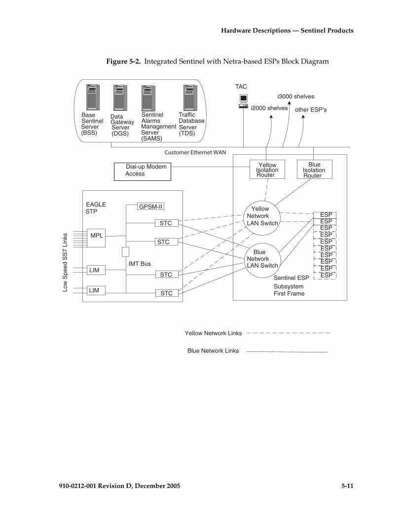
Hardware Descriptions — Sentinel Products
910-0212-001 Revision D, December 2005 5-11
Figure 5-2. Integrated Sentinel with Netra-based ESPs Block Diagram
LIM
ESP
LIMLow
Spe
ed S
S7
Link
s
GPSM-II
STC
other ESP’s
MPL
STC
STP
ESP ESP
ESP ESP
ESP ESP ESP
ESP ESP
STC
STC
LAN Switch
LAN SwitchIMT Bus
TAC
TrafficDatabaseServer(TDS)
i2000 shelves
i3000 shelves
IsolationRouter
IsolationRouter
Yellow Network Links
Dial-up ModemAccess
BlueNetwork
YellowNetwork
Sentinel ESPSubsystemFirst Frame
BaseSentinelServer(BSS)
DataGatewayServer(DGS)
SentinelAlarmsManagementServer(SAMS)
Blue Network Links
Yellow Blue
EAGLE
Customer Ethernet WAN
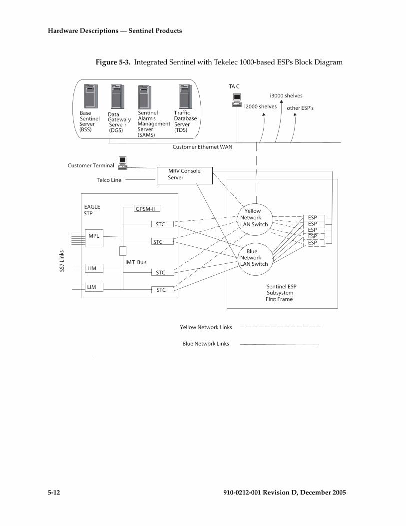
5-12 910-0212-001 Revision D, December 2005
Hardware Descriptions — Sentinel Products
Figure 5-3. Integrated Sentinel with Tekelec 1000-based ESPs Block Diagram
LIM
ESP
LIM
GPSM-II
STC
other ESP's
MPL
STC
STP
ESP ESP
ESP ESP
STC
STC
LAN Switch
LAN SwitchIMT Bu s
TA C
TrafficDatabaseServer(TDS)
Customer Ethernet WAN
i2000 shelves
i3000 shelves
Yellow Network Links
MRV ConsoleServer
BlueNetwork
YellowNetwork
Sentinel ESPSubsystemFirst Frame
BaseSentinelServer(BSS)
DataGatewa yServe r(DGS)
SentinelAlarm sManagementServer(SAMS)
Blue Network Links
EAGLE
SS7
Link
s
Customer Terminal
Telco Line
Hardware Descriptions — Sentinel Products
910-0212-001 Revision D, December 2005 5-13
Figure 5-4. Integrated Sentinel Netra-based ESP Frame Front View
Front View
Circuitbreakers
Server 1A
Server 1Q
Mountingbrackets for(17) ESP Servers
Ethernet Switch Yellow -1
sentin
el front
Drip pan
Breakout box
Router Yellow
Router Blue A
BC
D
E
F
GH
I
J
K
L
M
N
O
P
Q
A
BC
D
E
FGH
IJKL
M
N
OP
Q
Ethernet Switch Blue -1
Ethernet Switch BLue -2
Ethernet Switch Yellow -2
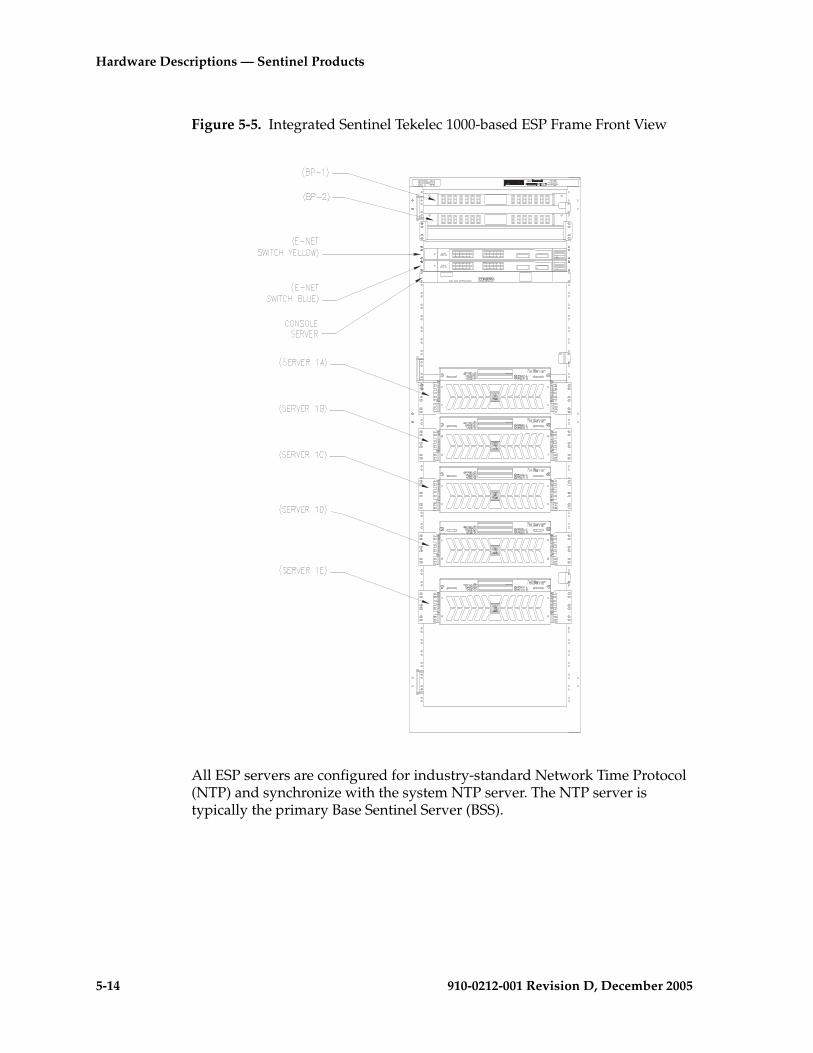
5-14 910-0212-001 Revision D, December 2005
Hardware Descriptions — Sentinel Products
Figure 5-5. Integrated Sentinel Tekelec 1000-based ESP Frame Front View
All ESP servers are configured for industry-standard Network Time Protocol (NTP) and synchronize with the system NTP server. The NTP server is typically the primary Base Sentinel Server (BSS).
CONSERV

Hardware Descriptions — Sentinel Products
910-0212-001 Revision D, December 2005 5-15
ESP Subsystem
ESP servers in the Integrated Sentinel are provisioned in an n+1 configuration for redundancy. The n+1 backup ESP server does not monitor any EAGLE ports during normal operation. The backup ESP server can be configured to replace any failed server. A major alarm will be raised when an Integrated Sentinel ESP server fails.All ESP servers plus the LAN equipment located at one EAGLE STP location are collectively called an “ESP Subsystem.”
The ESP subsystem supports multiple frames. The server installed at the top of the first frame is referred to as ESP 1A; the next lower server is ESP 1B, then ESP 1C continuing down to the final server. Labeling of ESP servers in the 2nd frame of an ESP subsystem begins with ESP 2A.
ESP Subsystem Hardware Components
The following sections describes ESP Subsystem hardware.
Netra-based ESP Frame Components Release 10.0
For Netra-based ESPs starting with Release 10.0, ESP servers in the first frame are designated from 1A through 1Q. ESP servers in the second frame are designated 2A through 2Q. See Figure 5-6, “Sentinel Netra-based ESP Rear View 1024 Links,” on page 5-16 shows the component locations of all three frames.
Table 5-3 lists the components configured in each frame for Sentinel release 10.0. See Table 5-4 on page 5-17 and Table 5-5 on page 5-18 for individual ESP server components for release 10.0.
NOTE: While Netra-based ESP Subsystem hardware design was completed to be able to handle a third frame, the three frame (1500 link) configuration has not yet been tested by Tekelec Product Verification.
Table 5-3. Netra-based ESP Frame Components Release 10.x and Higher
ComponentQuantityFirst Frame
Quantity Three Frame System
Frame Assembly One Two
Breaker Panels Two Four
Routers NOTE: Dial-up modem access card is in the Yellow router.
Two Two - Only required in first frame
24-Port DC ENET Switches Two or Four Eight Maximum
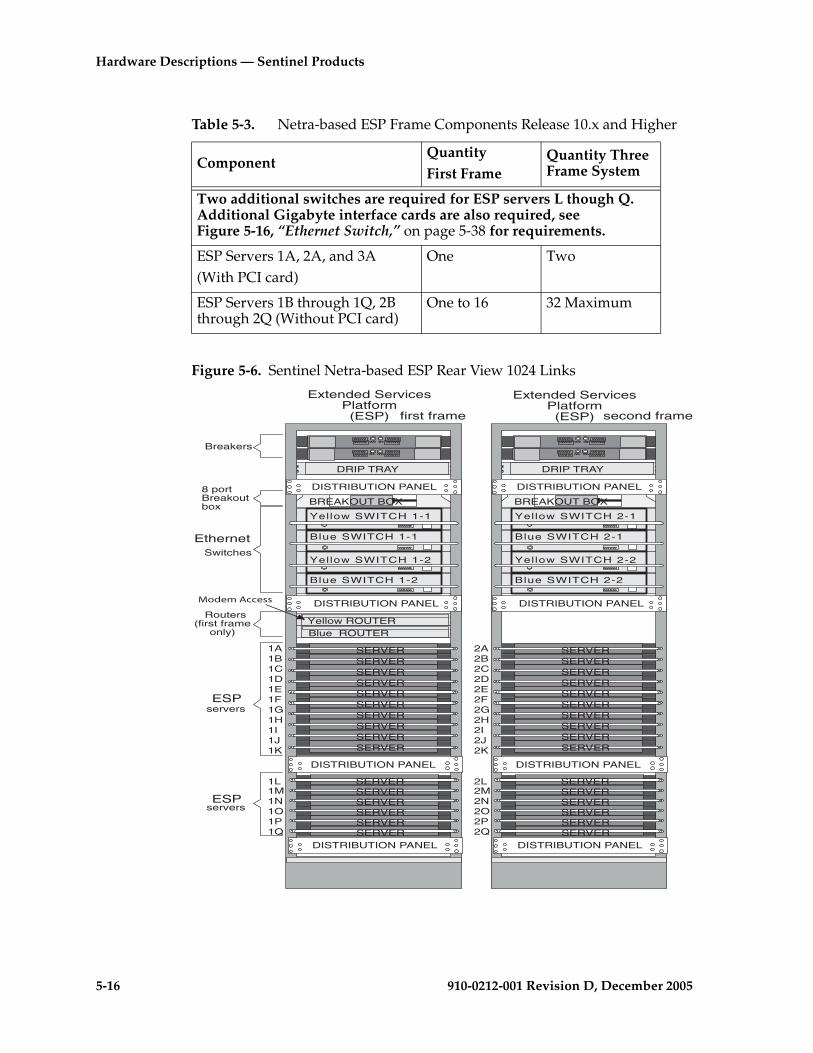
5-16 910-0212-001 Revision D, December 2005
Hardware Descriptions — Sentinel Products
Figure 5-6. Sentinel Netra-based ESP Rear View 1024 Links
Two additional switches are required for ESP servers L though Q. Additional Gigabyte interface cards are also required, see Figure 5-16, “Ethernet Switch,” on page 5-38 for requirements.
ESP Servers 1A, 2A, and 3A(With PCI card)
One Two
ESP Servers 1B through 1Q, 2B through 2Q (Without PCI card)
One to 16 32 Maximum
Table 5-3. Netra-based ESP Frame Components Release 10.x and Higher
ComponentQuantityFirst Frame
Quantity Three Frame System
first frame
BREAKOUT BOX
Yellow ROUTERBlue ROUTER
DRIP TRAY
DISTRIBUTION PANEL
DISTRIBUTION PANEL
DISTRIBUTION PANEL
DISTRIBUTION PANEL
1A1B1C1D1E1F1G1H1I1J1K
1L1M1N1O1P1Q
Blue SWITCH 1-1
Yellow SWITCH 1-1
Yellow SWITCH 1-2
Blue SWITCH 1-2
SERVERSERVERSERVERSERVERSERVERSERVERSERVERSERVERSERVERSERVER
SERVERSERVERSERVERSERVERSERVERSERVER
Breakers
servers
Switches
Routers(first frame
only)
8 portBreakoutbox
servers
BREAKOUT BOX
second frame
DRIP TRAY
DISTRIBUTION PANEL
DISTRIBUTION PANEL
DISTRIBUTION PANEL
DISTRIBUTION PANEL
2A2B2C2D2E2F2G2H2I2J2K
2L2M2N2O2P2Q
Blue SWITCH 2-1
Yellow SWITCH 2-1
Yellow SWITCH 2-2
Blue SWITCH 2-2
SERVERSERVERSERVERSERVERSERVERSERVERSERVERSERVERSERVERSERVER
SERVERSERVERSERVERSERVERSERVERSERVER
Extended ServicesPlatform(ESP)
Extended ServicesPlatform(ESP)
Modem Access
Ethernet
ESP
ESP

Hardware Descriptions — Sentinel Products
910-0212-001 Revision D, December 2005 5-17
ESP servers have specific configurations determined by the location in the frame, Table 5-4 lists components for servers in locations 1A or 2A.
ESP servers have specific configurations determined by the location in the frame. Table 5-5 lists components for servers in locations 1B through 1Q (Frame 1) and 2B through 2Q (Frame 2).
Table 5-4. ESP Servers 1A and 2A Release 10.0
Server Sub-Component Description
Netra 120 1x 650-MHz UltraSPARC-IIi CPU w/512-KB eCache, 1x512-MB Memory, 1x 36-GB 10000 UltraSCSI Disk, 2x 10/100 Mbit Ethernet, 2x USB Ports, UltraSCSI Port, Removable System Config Card, 19-in Rackmount Kit, Solaris 8 & LomLite2DC Power Supply
(2x 512-MB DIMM) PC133 ECC Reg/Buffered Memory ExpansionPC133 ECC DIMM, Reg/Buffered
HARD DISK 36.4 GB NEBS USCSI
CDROM DRIVE
PCI SERIAL ASYNCHRONOUS INTERFACEADAPTER CARD (INCLUDES 8 PORT DB-25 BREAKOUT BOX) ASSY and cable
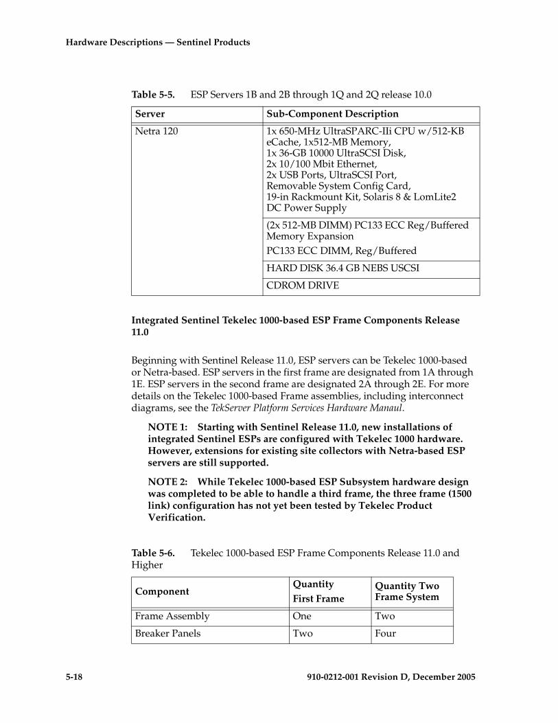
5-18 910-0212-001 Revision D, December 2005
Hardware Descriptions — Sentinel Products
Integrated Sentinel Tekelec 1000-based ESP Frame Components Release 11.0
Beginning with Sentinel Release 11.0, ESP servers can be Tekelec 1000-based or Netra-based. ESP servers in the first frame are designated from 1A through 1E. ESP servers in the second frame are designated 2A through 2E. For more details on the Tekelec 1000-based Frame assemblies, including interconnect diagrams, see the TekServer Platform Services Hardware Manaul.
NOTE 1: Starting with Sentinel Release 11.0, new installations of integrated Sentinel ESPs are configured with Tekelec 1000 hardware. However, extensions for existing site collectors with Netra-based ESP servers are still supported.
NOTE 2: While Tekelec 1000-based ESP Subsystem hardware design was completed to be able to handle a third frame, the three frame (1500 link) configuration has not yet been tested by Tekelec Product Verification.
Table 5-5. ESP Servers 1B and 2B through 1Q and 2Q release 10.0
Server Sub-Component Description
Netra 120 1x 650-MHz UltraSPARC-IIi CPU w/512-KB eCache, 1x512-MB Memory,1x 36-GB 10000 UltraSCSI Disk, 2x 10/100 Mbit Ethernet, 2x USB Ports, UltraSCSI Port, Removable System Config Card, 19-in Rackmount Kit, Solaris 8 & LomLite2DC Power Supply
(2x 512-MB DIMM) PC133 ECC Reg/Buffered Memory Expansion PC133 ECC DIMM, Reg/Buffered
HARD DISK 36.4 GB NEBS USCSI
CDROM DRIVE
Table 5-6. Tekelec 1000-based ESP Frame Components Release 11.0 and Higher
ComponentQuantityFirst Frame
Quantity Two Frame System
Frame Assembly One Two
Breaker Panels Two Four

Hardware Descriptions — Sentinel Products
910-0212-001 Revision D, December 2005 5-19
MRV Console Servers (including RAS modem)
One Two
24-Port DC ENET Switches Two Four
Tekelec 1000 ESP Servers 1A and 2A(With 2 Port Ethernet card and 4 port serial expansion card)
One Two
ESP Servers 1B through 1E, 2B through 2E (with 2 port Ethernet Card)
One to Four Eight Maximum
Table 5-6. Tekelec 1000-based ESP Frame Components Release 11.0 and Higher
ComponentQuantityFirst Frame
Quantity Two Frame System

5-20 910-0212-001 Revision D, December 2005
Hardware Descriptions — Sentinel Products
Sentinel Probe Based Site Collector
See Figure 5-7 "Probe Based Sentinel System Configuration" on page 5-21 for an overview of the probe based Sentinel solution using the combined i2000/FR Site Collector Frame.
The i2000/FR probe based Site Collector frames consist of the following hardware components:
• Breaker Panels
• Hubs
• Flight Recorders (Netra 120 servers)
• I2000 probes
See Figure 5-8 for the location of the components in the Site Collector frame.
NOTE 1: For more information about the i2000 shelf refer to the Signaling/Cellular Generic Hardware Reference Manual (P/N 910-2277-01). This manual is included with this Documentation suite.
NOTE 2: The i2000 shelf (P/N 890-1028-02) described in this document is -48 VDC powered. Some i2000 shelves documented in the Signaling/Cellular Generic Hardware Reference Manual were AC powered.
Various types of link interface module (LIM) cards are available for different probe shelves. For information about link interface modules (LIM) in the i2000 see Chapter B, Sentinel 4-Port Monitor Appliques, in this manual.
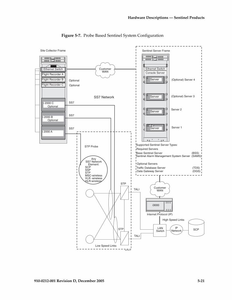
Hardware Descriptions — Sentinel Products
910-0212-001 Revision D, December 2005 5-21
Figure 5-7. Probe Based Sentinel System Configuration
TALI
TALI
SS7
Site Collector Frame
i 2000 A
i 2000 B
i 2000 C
SS7
SS7
CustomerWAN
SS7 Network
Flight Recorder A
Flight Recorder B
Flight Recorder C
Server 2
Sentinel Server Frame
Server
Server
Server
Server
SCPIP
Network
i3000
CustomerWAN
High Speed Links
Internet Protocol (IP)
LANSwitch
sentinel d
STP Probe
STP
STP
AnySS7 Network
Element:SCPSSPSTPMSC-wirelessVLR -wirelessHLR-wireless
Low Speed Links
(Optional) Server 4
(Optional) Server 3
Server 1
Supported Sentinel Server Types:
Base Sentinel Server (BSS)
Traffic Database Server (TDS)
Sentinel Alarm Management System Server (SAMS)
Data Gateway Server (DGS)
Optional
Optional
Optional
Optional
Ethernet Switch Ethernet SwitchConsole Server
Optional Servers
Required Servers
5-22 910-0212-001 Revision D, December 2005
Hardware Descriptions — Sentinel Products
Site Collector Frames
The frame configuration for a combined i2000/FR probe based site collector was introduced with Sentinel Release 9.0. Along with this change the Flight Recorder (FR) hardware selected was the same Netra 120 used in the integrated Sentinel configuration. This Netra based FR borrowed specific functionalities from the Netra ESP server design for the processing, database, and site collector storage functions. For the i2000/FR probe based site collector, the i2000 probe shelf provides the data acquisition function via a direct physical tap of the external SS7 links connecting to the STP. Link taps are typically made at the DSX panel. For the case of E1, T1, or DSCS taps that are some distance from the i2000 probe shelf a bridge amplifier may be used to provide a "non-intrusive" tap of the SS7 link.
Figure 5-8 on page 5-23 describes the frame layout for the i2000/FR Site Collector frame.

Hardware Descriptions — Sentinel Products
910-0212-001 Revision D, December 2005 5-23
Figure 5-8. Site-Collector Frame
i2000 Shelf C (Optional)
sentinel site collector
Circuit Breaker
Drip Tray
Flight Recorder A (Netra 120)
Breakout Box andCable Part of SAI/P Card
Flight Recorder ACircuit Breaker
Flight Recorder B (Netra 120)
Flight Recorder C (Netra 120)
i2000 Shelf B (Optional)
i2000 Shelf A
Hub
(Optional)
(Optional)
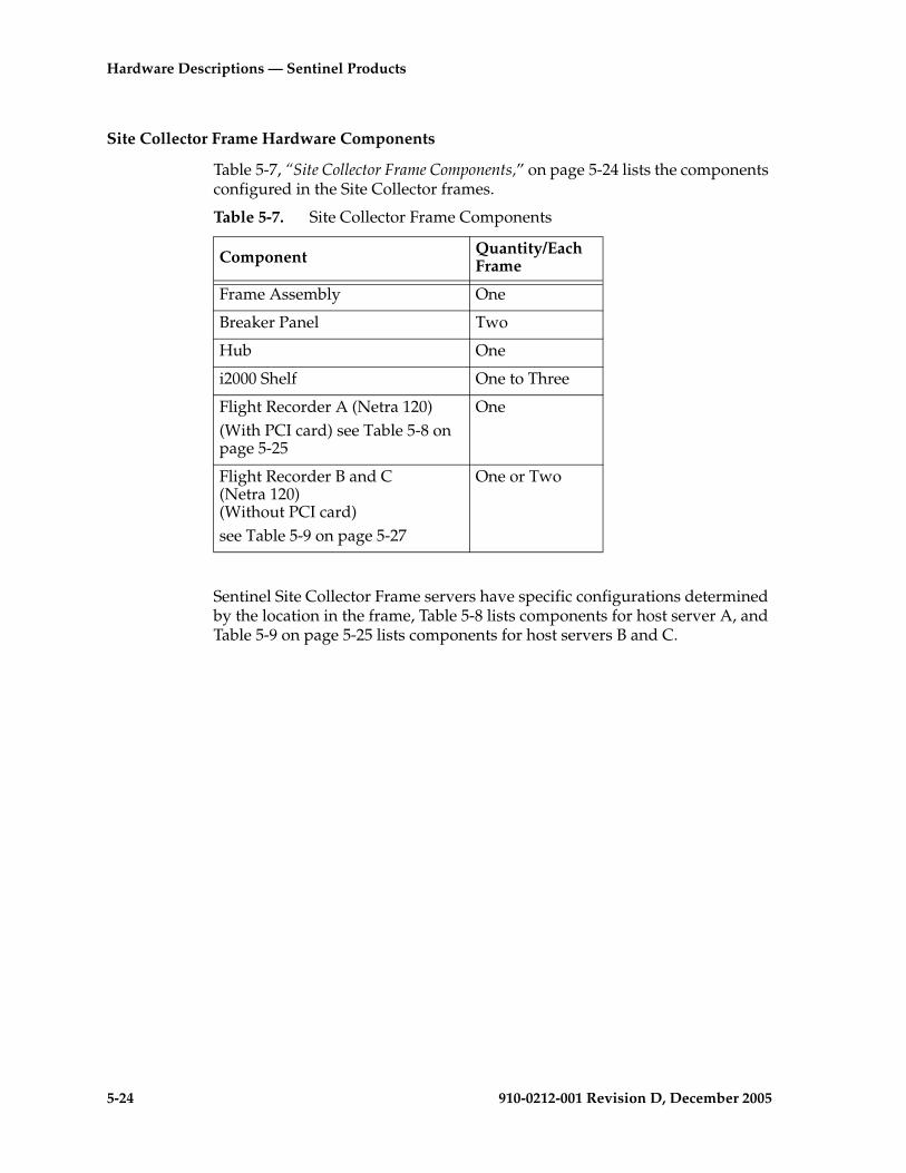
5-24 910-0212-001 Revision D, December 2005
Hardware Descriptions — Sentinel Products
Site Collector Frame Hardware Components
Table 5-7, “Site Collector Frame Components,” on page 5-24 lists the components configured in the Site Collector frames.
Sentinel Site Collector Frame servers have specific configurations determined by the location in the frame, Table 5-8 lists components for host server A, and Table 5-9 on page 5-25 lists components for host servers B and C.
Table 5-7. Site Collector Frame Components
Component Quantity/Each Frame
Frame Assembly One
Breaker Panel Two
Hub One
i2000 Shelf One to Three
Flight Recorder A (Netra 120)(With PCI card) see Table 5-8 on page 5-25
One
Flight Recorder B and C (Netra 120)(Without PCI card)see Table 5-9 on page 5-27
One or Two
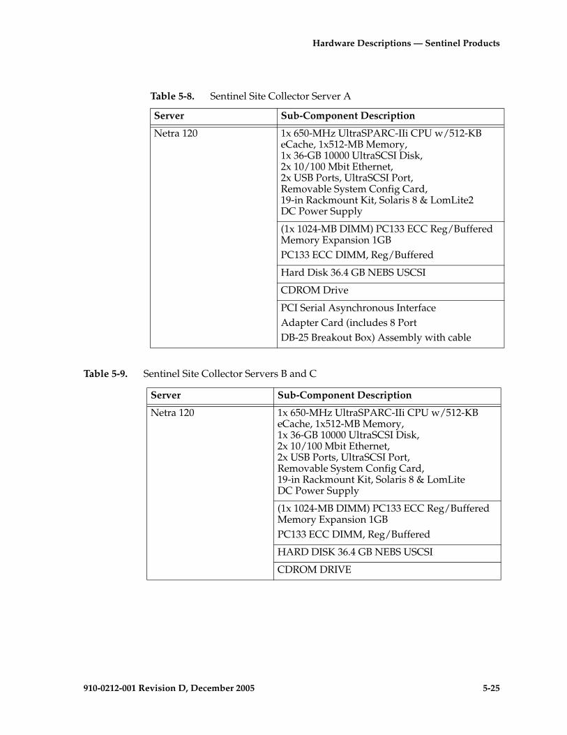
Hardware Descriptions — Sentinel Products
910-0212-001 Revision D, December 2005 5-25
Table 5-9. Sentinel Site Collector Servers B and C
Table 5-8. Sentinel Site Collector Server A
Server Sub-Component Description
Netra 120 1x 650-MHz UltraSPARC-IIi CPU w/512-KB eCache, 1x512-MB Memory, 1x 36-GB 10000 UltraSCSI Disk, 2x 10/100 Mbit Ethernet, 2x USB Ports, UltraSCSI Port, Removable System Config Card,19-in Rackmount Kit, Solaris 8 & LomLite2DC Power Supply
(1x 1024-MB DIMM) PC133 ECC Reg/Buffered Memory Expansion 1GBPC133 ECC DIMM, Reg/Buffered
Hard Disk 36.4 GB NEBS USCSI
CDROM Drive
PCI Serial Asynchronous InterfaceAdapter Card (includes 8 Port DB-25 Breakout Box) Assembly with cable
Server Sub-Component Description
Netra 120 1x 650-MHz UltraSPARC-IIi CPU w/512-KB eCache, 1x512-MB Memory, 1x 36-GB 10000 UltraSCSI Disk, 2x 10/100 Mbit Ethernet, 2x USB Ports, UltraSCSI Port, Removable System Config Card, 19-in Rackmount Kit, Solaris 8 & LomLiteDC Power Supply
(1x 1024-MB DIMM) PC133 ECC Reg/Buffered Memory Expansion 1GBPC133 ECC DIMM, Reg/Buffered
HARD DISK 36.4 GB NEBS USCSI
CDROM DRIVE
5-26 910-0212-001 Revision D, December 2005
Hardware Descriptions — Sentinel Products
Sentinel Central Server Frames
The Sentinel Central Server Frame, typically located at the Network Operations Center (NOC) or other central location, is configured with one to four servers. The Sentinel Central Server Frame contains the following:
• one or more Base Sentinel Servers (BSS)• one or more Data Gateway Servers (DGS)• one Sentinel Alarm Management System (SAMS) server (only one per
system)• one Traffic Database Server (only one per system)
The BSS, SAMS, and DGS are supported by Netra 20 servers. More than one Sentinel Central Server Frame can be equipped in the system to support additional BSS.
For releases prior to Sentinel Release 11.3 the Traffic Database Server used the Oracle database and was supported on older legacy server hardware. Starting with Release 11.3 the TDS is supported on the DC powered Tekelec 1000 server. No AC configuration is supported. See the Tekelec 1000 Applications Server Hardware Manual for more information on Tekelec 1000-based TDS.
Figure 5-9, on page 5-27 illustrates all types of Sentinel site collectors and the interconnections through the customer’s WAN to a Sentinel server frame. The block diagram shown in Figure 5-9 depicts system configuration with the possible site collector configurations and the connections between the monitored SS7 links, site collectors, and a Sentinel server frame.
NOTE: In all of the site collector configurations except the probe-less connections in the “Integrated Solution” the probe connections are physically tapped to SS7 links. In the “Integrated Solution” the probed link data acquisition is handled by the EAGLE STP.

Hardware Descriptions — Sentinel Products
910-0212-001 Revision D, December 2005 5-27
Figure 5-9. Site Collectors Connections to a Sentinel Central Server Frame
Site Collector Frame
i 2000 A
i 2000 B
i 2000 C
Customer
WAN
Flight Recorder A
Flight Recorder B
Flight Recorder C
Server 2
Sentinel Server Frame
Server
Server
Server
Server
(Optional) Server 4
(Optional) Server 3
Server 1
Supported Sentinel Server Types:
Base Sentinel Server (BSS)
Traffic Database Server (TDS)
Sentinel Alarm Management System Server (SAMS)
Data Gateway Server (DGS)
Optional
Optional
Ethernet Switch
Ethernet SwitchConsole Server
Optional Servers
Required Servers
CF00
0102030405060708091112131415161718
0102030405060708101112131415161718
0102030405060708091112131415161718
0102030405060708101112131415161718
0102030405060708091112131415161718
0102030405060708101112131415161718
EAGLE STP
1A1B
1C
)
)
1D1E1F1G1H1I1J1K
1L
1N1O1P1Q
ESP Frame
1M
Control
SS7 Links
SS7 Links
To STCCards inSTP
Shelf
Extension Shelf
ShelfExtension
EthernetSwitches
Routers1A1B
1C
)
)
1D1E1F1G1H1I1J1K
1L
1N1O1P1Q
ESP Frame
1M
EthernetSwitches
Routers
Integrated Solution 500 Links
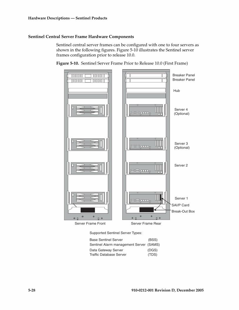
5-28 910-0212-001 Revision D, December 2005
Hardware Descriptions — Sentinel Products
Sentinel Central Server Frame Hardware Components
Sentinel central server frames can be configured with one to four servers as shown in the following figures. Figure 5-10 illustrates the Sentinel server frames configuration prior to release 10.0.
Figure 5-10. Sentinel Server Frame Prior to Release 10.0 (First Frame)
Server Frame Front Server Frame Rear
Breaker PanelBreaker Panel
Break-Out Box
Hub
SAI/P Card
Supported Sentinel Server Types:
Base Sentinel Server (BSS)
Traffic Database Server (TDS)
Sentinel Alarm management Server (SAMS)
Data Gateway Server (DGS)
Server 1
Server 4
Server 3
Server 2
(Optional)
(Optional)

Hardware Descriptions — Sentinel Products
910-0212-001 Revision D, December 2005 5-29
Several changes were made to the Sentinel sever frames in release 10.0. The hub component for the internal LAN was changed to an ethernet switch. Also the external remote access server (RAS) function was replaced with a console/alarm (CAS) server configured in the frame. The CAS provides interconnectivity to all frame components and dial-up modem service access to the frame. Release 10.0 changes are listed in Table 5-14, “Sentinel Central Server Components Release 10.0,” on page 5-32.
Figure 5-11. Sentinel Central Server Frame Release 10.0 (First Frame)
Server Frame Front Server Frame Rear
Breaker PanelBreaker Panel
(Optional)
Server 1
Supported Sentinel Server Types:
Base Sentinel Server (BSS)
Traffic Database Server (TDS)Sentinel Alarm management Server (SAMS)
Data Gateway Server (DGS)
Ethernet Switch
Server 4
Server 3
Server 2
(Optional)
Console/AlarmServer
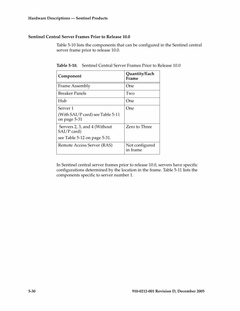
5-30 910-0212-001 Revision D, December 2005
Hardware Descriptions — Sentinel Products
Sentinel Central Server Frames Prior to Release 10.0
Table 5-10 lists the components that can be configured in the Sentinel central server frame prior to release 10.0.
In Sentinel central server frames prior to release 10.0, servers have specific configurations determined by the location in the frame. Table 5-11 lists the components specific to server number 1.
Table 5-10. Sentinel Central Server Frames Prior to Release 10.0
Component Quantity/Each Frame
Frame Assembly One
Breaker Panels Two
Hub One
Server 1(With SAI/P card) see Table 5-11 on page 5-31
One
Servers 2, 3, and 4 (Without SAI/P card)see Table 5-12 on page 5-31.
Zero to Three
Remote Access Server (RAS) Not configured in frame

Hardware Descriptions — Sentinel Products
910-0212-001 Revision D, December 2005 5-31
Table 5-11. Sentinel Central Server 1 Prior to Release 10.0
Server Sub-Component Description
Netra 20 DC Power
1x 900-MHz UltraSPARC-III CPU w/8MB eCache,
NOTE: One processor card standard for TDS, DGS, and BSS servers. Additional processor card required for SAMS server.
2GB (4x512-MB) DIMMS Memory Expansion
HARD DISK 73 GB NEBS Hot Swap Capability
Single Fast Ethernet, PCI
DVD/ROM DRIVE
SERIAL ASYNCHRONOUS INTERFACE PCI (SAI/P) ADAPTER CARD (INCLUDES 8 PORT DB-25 BREAKOUT BOX) ASSY and cable
Table 5-12. Sentinel Central Servers 2, 3, 4 Components Prior to Release 10.0
Server Sub-Component Description
Netra 20 DC Power
1x 900-MHz UltraSPARC-III CPU w/8MB eCache,
NOTE: One processor card standard for TDS, DGS, and BSS servers. Additional processor card required for SAMS server.
2GB (4x512-MB) DIMMS Memory Expansion
HARD DISK 73 GB NEBS USCSI
Single Fast Ethernet, PCI
DVD/ROM DRIVE

5-32 910-0212-001 Revision D, December 2005
Hardware Descriptions — Sentinel Products
Sentinel Central Server Frames Release 10.0
Table 5-13 lists the components that can be configured in all Sentinel central server frames in release 10.0.
Beginning in Sentinel release 10.0 all servers in Sentinel Central Server frames are configured with the components listed in Table 5-14.
Table 5-13. Sentinel Central Server Frames Release 10.0
Component Quantity/Each Frame
Frame Assembly One
Breaker Panel Two
Console/Alarm Server (CAS) One
Ethernet Switch One
Netra 20 Servers One to Four
Table 5-14. Sentinel Central Server Components Release 10.0
Server Sub-Component Description
Netra 20 DC Power
2x 1200-MHz UltraSPARC-III CPU w/8MB eCache,
NOTE: Two processor cards standard.
2GB (4x512-MB) DIMMS Memory Expansion
Two Hard Disks 73 GB NEBS with Hot Swap Capability
Single Fast Ethernet, PCI
DVD ROM DRIVE

Hardware Descriptions — Sentinel Products
910-0212-001 Revision D, December 2005 5-33
Netra 20 DC Power
2x 1200-MHz UltraSPARC-III CPU w/8MB eCache,
NOTE: Two processor cards standard.
2GB (4x512-MB) DIMMS Memory Expansion
Two Hard Disks 73 GB NEBS with Hot Swap Capability
Single Fast Ethernet, PCI
DVD ROM DRIVE
Table 5-15. Traffic Database Server Release 11.3
Server Sub-component Description
Tekelec 1000 DC Power
NOTE: See Tekelec 1000 Applications Server Hardware Manual for details
Table 5-14. Sentinel Central Server Components Release 10.0 (Continued)
Server Sub-Component Description

5-34 910-0212-001 Revision D, December 2005
Hardware Descriptions — Sentinel Products
Sentinel Frames Common Components
This section describes the common components that can be used in Sentinel-based products.
Common components described in this section include:
• Breaker Panels
• Serial Interface cards
• Breakout Boxes
• Ethernet Switches
• Routers
• Hubs
• Console Servers
• Link Interface Cards (Monitoring)
Breaker Panels
The following section describes the components of the Telect
Breaker Panels (BP) used in Sentinel products. The BPs provide the following features:
• Dual-feed power inputs (Input A and Input B) to each breaker panel, totalling four breakers for the system. (40-amp domestic or 32-amp international)
• Maximum of fourteen breakers each breaker panel
• Visual A and B input power alarms with single remote dry contact indicator
• Replaceable alarm card (Hot swappable with power ON at the frame)
The drip tray, located under the breaker panels, is designed to assure compliance with NEBS, UL, and CE safety requirements, aiding damage control in the event of a fire. Figure 5-12 "Telect Breaker Panel Front View" on page 5-35 shows the details of the front view of the breaker panel.
NOTE: A Breaker is labeled with the component designation that is powered by it. Components are typically redundantly powered from both the A and B buses. Breakers on both buses must be turned OFF before removing this type of component.
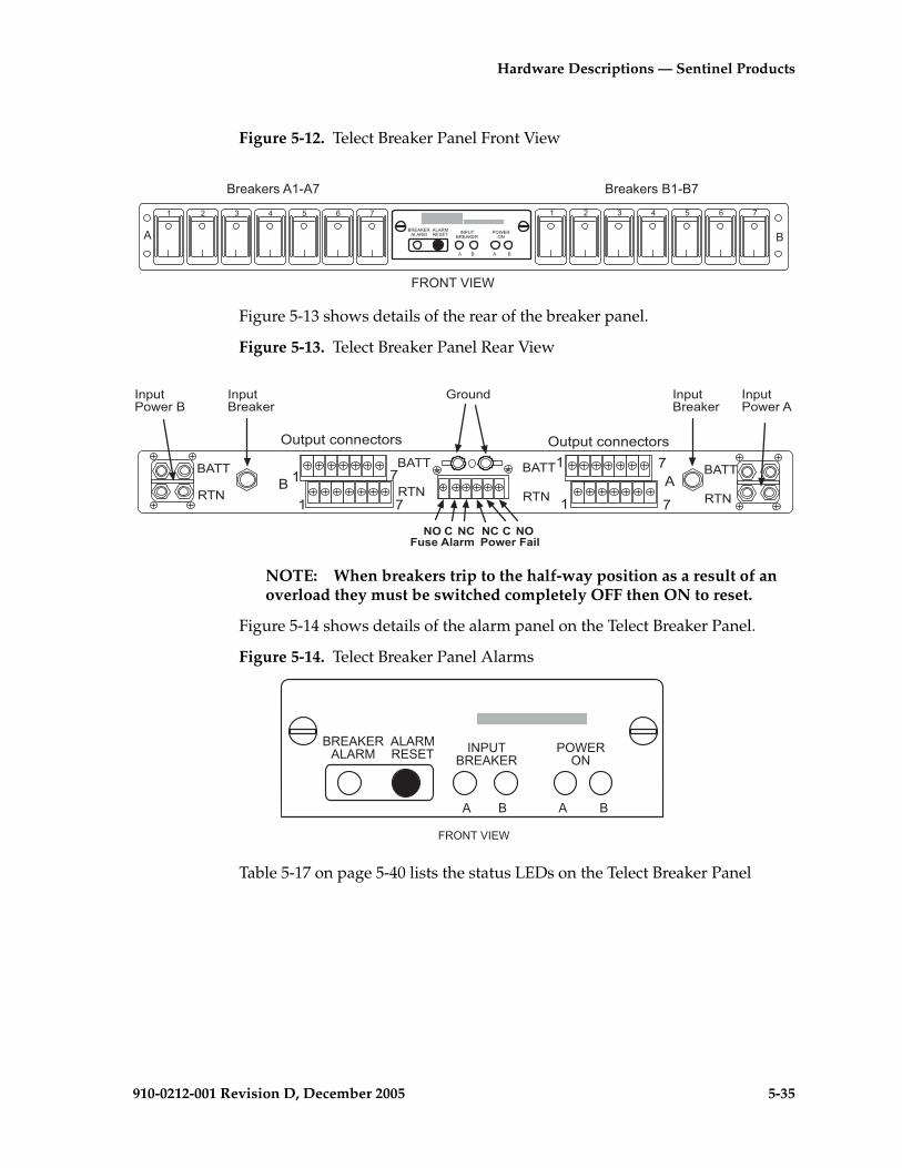
Hardware Descriptions — Sentinel Products
910-0212-001 Revision D, December 2005 5-35
Figure 5-12. Telect Breaker Panel Front View
Figure 5-13 shows details of the rear of the breaker panel.
Figure 5-13. Telect Breaker Panel Rear View
NOTE: When breakers trip to the half-way position as a result of an overload they must be switched completely OFF then ON to reset.
Figure 5-14 shows details of the alarm panel on the Telect Breaker Panel.
Figure 5-14. Telect Breaker Panel Alarms
Table 5-17 on page 5-40 lists the status LEDs on the Telect Breaker Panel
������������
�������� �� �
������� ������
� � � �
� �
�������������� ��������������
� � � � � � � � � � � � � �
����� ���
� �� �
� �
� �
� �
��
�!"#!"�$%&&�$"%�� �!"#!"�$%&&�$"%��
��
��
��
��
��
��
��
�&#!"�������
�&#!"�������
'�%!&(
�& �)�*�����+�,
) �) �&#-.����+�
)
�&#!" %)����
�&#!" %)����
����� ���
������������
�������� �� �
������� ������
� � � �

5-36 910-0212-001 Revision D, December 2005
Hardware Descriptions — Sentinel Products
NOTE: If all breakers are not turned on, the alarm LED will light. To turn off the alarm LED, press RESET and the alarm LED will reset and turn off.
SAI/P Card
The SAI/P card (Serial Asynchronous Interface PCI Adapter) is used with the 8-Port Break-Out Box to provide eight programmable ports for low-speed devices for 50 bps to 115,200 bps transmission for the subsystem.
8-Port Break-Out Box
The 8-Port Break-Out Box segments the output of the SAI/P card into eight DB-25 ports for the Sentinel subsystem. This box connects to the SAI/P card with a 78-pin plug on a 40-inch cable. See Figure 5-15 "8-Port Break-Out Box" on page 5-37 for a view of the Break-Out Box.
Ethernet Interface Cards
Provide interfaces to local area networks (LAN) connecting servers, routers, ethernet switches, and hubs internally and to other frames or networks. Ethernet cards support 10/100 Mbyte connections.
Table 5-16. Breaker Panel (BP) LEDs
LED Color Description
Power On A Green Lights whenever Side A is receiving input power (LED will remain lit even if the input breaker has tripped)
Power On B Green Lights whenever Side B is receiving input power (LED will remain lit even if the input breaker has tripped)
BreakerAlarm
Red Lights whenever an output circuit breaker has tripped or turned off
Input Breaker A/B
Green Lights whenever Side A/B is receiving input power (Not lit if input breaker is tripped)

Hardware Descriptions — Sentinel Products
910-0212-001 Revision D, December 2005 5-37
Figure 5-15. 8-Port Break-Out Box
Ethernet Switches
The following section provides an overview of the Ethernet LAN switches used in some Sentinel products. The ethernet switches cross-connect the components in the frames functioning as an internal LAN. The switches support 24 auto-sensing 10/100Mbps ports each.
Cisco 2900 Ethernet Switches
See Figure 5-16 and refer to Table 5-17 on page 5-39 for definitions of the LEDs. Four configurations are shown with the optional Gigabit ethernet cards installed. These yellow and blue switch 2 cards are configured when additional optional servers are installed in the frame.
Viewed from back of frame
8 Port Breakout Box
sentinel breakout box
78 pin connector
8 Port Breakout Box
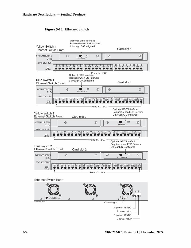
5-38 910-0212-001 Revision D, December 2005
Hardware Descriptions — Sentinel Products
Figure 5-16. Ethernet Switch
Ethernet Switch Rear
Chassis gnd
A power 48VDC
B power 48VDC
B power return
A power return
sentinel ether switch 1
CONSOLE
Ethernet Switch Front
15X1X 2X 3X 4X 5X 6X 7X 8X 9X 10X 11X 12X 13X 14X 16X 17X 18X 19X 20X 21X 22X 23X 24X
SYSTEM
UTL FDUP
MODE
RPS
STAT
1 2 1000 Base T
Ports 1X 24X
Yellow Switch 1Card slot 1
Ethernet Switch Front
15X1X 2X 3X 4X 5X 6X 7X 8X 9X 10X 11X 12X 13X 14X 16X 17X 18X 19X 20X 21X 22X 23X 24X
SYSTEM
UTL FDUP
MODE
RPS
STAT
1 2 1000 Base T
Ports 1X 24X
Blue Switch 1Card slot 1
Ethernet Switch Front
15X1X 2X 3X 4X 5X 6X 7X 8X 9X 10X 11X 12X 13X 14X 16X 17X 18X 19X 20X 21X 22X 23X 24X
SYSTEM
UTL FDUP
MODE
RPS
STAT
1 2 1000 Base T
Ports 1X 24X
Yellow switch 2Card slot 2
Ethernet Switch Front
15X1X 2X 3X 4X 5X 6X 7X 8X 9X 10X 11X 12X 13X 14X 16X 17X 18X 19X 20X 21X 22X 23X 24X
SYSTEM
UTL FDUP
MODE
RPS
STAT
1 2 1000 Base T
Ports 1X 24X
Blue switch 2Card slot 2
Optional GBIT InterfaceRequired when ESP ServersL through Q Configured
Optional GBIT InterfaceRequired when ESP ServersL through Q Configured
Optional GBIT InterfaceRequired when ESP ServersL through Q Configured
Optional GBIT InterfaceRequired when ESP ServersL through Q Configured

Hardware Descriptions — Sentinel Products
910-0212-001 Revision D, December 2005 5-39
Table 5-17 describes the LEDs located on the front of the switches.
Table 5-17. Ethernet Switch LEDs
LED Description
System Green-Indicates when power is present to the switch and the power switch is in the ON position.Amber-Indicates power is present but system is not functioning properly.
1 and 2 Indicates expansion boards WS-X2932-XL are installed and functioning LED 1 (Left board) LED 2 (Right board).
RPS(Always OFF)
Off when the redundant power supply is not present.Redundant power supply is not configured.
Pressing the MODE switch on the front of the WS-C2924-XL-EN changes the per-port LED indications to the following.
STAT (port status) Default
Off-No link.Solid green-Link present.Flashing green-Activity. Port is transmitting or receiving data.Alternating green/amber-Link fault. Error frames can affect connectivity, and errors such as excessive collisions, CRC errors, and alignment and jabber errors are monitored for a link-fault indication.Solid amber-Port is not forwarding. Port was disabled by management or an address violation or was blocked by Spanning Tree Protocol (STP).
NOTE: After a port is reconfigured, the port LED can remain amber for up to 30 seconds as the STP checks the switch for possible loops.
UTL (utilization)
Green-The LEDs display backplane utilization on a logarithmic scuffle all port LEDs are green, the switch is using 50 percent or more of its total bandwidth capacity. If the right-most LED is amber, the switch is using less than 50 percent of its total bandwidth. If the LED to the left of the right-most LED is amber, the switch is using less than 25 percent of its total capacity, and so on.
FDUP (port full-duplex)
Off-Port is operating in half duplex.Green-Port is operating in full duplex.
100 (port speed)
Off-Port is operating at 10 Mbps.Green-Port is operating at 100 Mbps.

5-40 910-0212-001 Revision D, December 2005
Hardware Descriptions — Sentinel Products
Garrettcom Ethernet Switch
Ethernet Switch with 24 RJ-45 ports, each auto-sensing for 10Mbps/100Mbps FDX/HDX operation. Optional fiber ports may be configured. Each RJ-45 port is switched and provides a full-speed traffic domain with non-blocking performance. LEDs are located in the front of the switch, power input and port connections are in the rear. See Figure 5-17, “Ethernet Switch,” on page 5-40 and reference Table 5-18, “Ethernet Switch LEDs Each Port,” on page 5-40.
Figure 5-17. Ethernet Switch
Table 5-18. Ethernet Switch LEDs Each Port
LED Description
LNK/ACT Link active - ON for Link with no traffic, blinking indicates port is transmitting and receiving.
FDX/COL ON = Full-Duplex ModeBLINKING = Half-Duplex Collision
100/10 ON = 100 Mbps speedOFF = 10 Mbps
Ethernet RJ-45
1XFan vents
Rear View detail
1
2
3
4
5
6
7
8
9
10
11
12
13
14
15
16 18
19
20 22 24
17 21 23
1X
OFFON
Uplink
+A -A -B +B
Chassis GND
A power return
A power -48VDC
B power -48VDCB power return
Front View detail
Col/FDXLink/Act
100M
Col/FDXLink/Act
100MPower
sen 10 ssf switch 24 prt
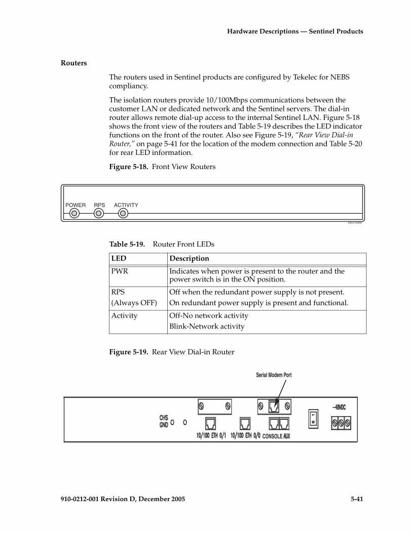
Hardware Descriptions — Sentinel Products
910-0212-001 Revision D, December 2005 5-41
Routers
The routers used in Sentinel products are configured by Tekelec for NEBS compliancy.
The isolation routers provide 10/100Mbps communications between the customer LAN or dedicated network and the Sentinel servers. The dial-in router allows remote dial-up access to the internal Sentinel LAN. Figure 5-18 shows the front view of the routers and Table 5-19 describes the LED indicator functions on the front of the router. Also see Figure 5-19, “Rear View Dial-in Router,” on page 5-41 for the location of the modem connection and Table 5-20 for rear LED information.
Figure 5-18. Front View Routers
Figure 5-19. Rear View Dial-in Router
POWER RPS ACTIVITY
cisco router
Table 5-19. Router Front LEDs
LED Description
PWR Indicates when power is present to the router and the power switch is in the ON position.
RPS(Always OFF)
Off when the redundant power supply is not present.On redundant power supply is present and functional.
Activity Off-No network activityBlink-Network activity
CONSOLE
Serial Modem Port

5-42 910-0212-001 Revision D, December 2005
Hardware Descriptions — Sentinel Products
Hubs
The following section provides an overview of the Ethernet hubs used in Sentinel products. The hubs cross-connect the components in Sentinel frames functioning as an internal Local Area Network (LAN). The hubs support self sensing dual-speeds and a maximum of sixteen RJ-45 ports each. The chip technology enables hubs to identify and accept either 100 Mb or 10 Mb LAN interfaces on a per-port basis. See Figure 5-20 "Hub Front View" on page 5-42 and Figure 5-21 "Hub Rear View" on page 5-42.
Figure 5-20. Hub Front View
Figure 5-21. Hub Rear View
Table 5-21 describes the LEDs located on the front of the hubs.
Table 5-20. Router Rear LEDs
LED Description
LNK Indicates link is established to far end connection.
ACT Blink-indicates data activity on the link.
Table 5-21. Hub Front LEDs
LED Color Description
PWR Green Lights whenever the power is applied
1 2 3 4 5 6 7 8 9 10 11 12 13 14 15 16
PWR BR
COL 10
COL 100
LX/RX
PORT
Ethernet Hub
������������
� ����
��� ����
�� �� �� �� �� ��� � � � � � � � � ����
�
!" #" #$ !$
��� �����%
�&
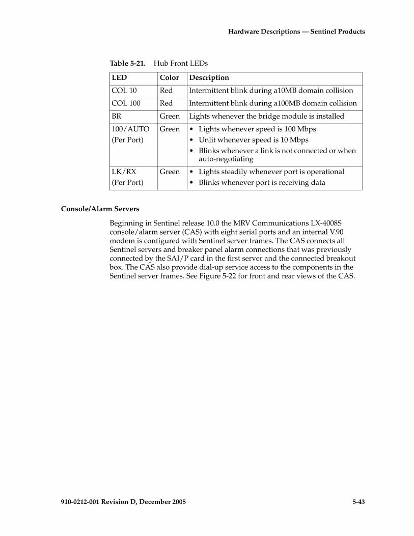
Hardware Descriptions — Sentinel Products
910-0212-001 Revision D, December 2005 5-43
Console/Alarm Servers
Beginning in Sentinel release 10.0 the MRV Communications LX-4008S console/alarm server (CAS) with eight serial ports and an internal V.90 modem is configured with Sentinel server frames. The CAS connects all Sentinel servers and breaker panel alarm connections that was previously connected by the SAI/P card in the first server and the connected breakout box. The CAS also provide dial-up service access to the components in the Sentinel server frames. See Figure 5-22 for front and rear views of the CAS.
COL 10 Red Intermittent blink during a10MB domain collision
COL 100 Red Intermittent blink during a100MB domain collision
BR Green Lights whenever the bridge module is installed
100/AUTO(Per Port)
Green • Lights whenever speed is 100 Mbps• Unlit whenever speed is 10 Mbps• Blinks whenever a link is not connected or when
auto-negotiating
LK/RX(Per Port)
Green • Lights steadily whenever port is operational• Blinks whenever port is receiving data
Table 5-21. Hub Front LEDs
LED Color Description

5-44 910-0212-001 Revision D, December 2005
Hardware Descriptions — Sentinel Products
Figure 5-22. Console/Alarm Server (CAS)
TELCOLINE
RCV LINK
DIAG 10/100 ETHNT
100
1 2 3 4 5 6 7 8
Console Server Rear
Modem port
DIAG Port (Port 0)
10/100Interface
100 MbpsLED
Front Panel LEDs
Console Server Front
FLT OK 1 2 3 4 5 6 7 8
sen 10 ssf console server
Console Server Terminal Bock

910-0212-001 Revision D, December 2005 6-1
6
Site EngineeringEAGLE 5 SAS STP/IP7-Based Systems
Safety and Cautionary Information...............................................................6–2
Introduction ......................................................................................................6–2
Location .............................................................................................................6–2
Space Requirements ..................................................................................6–2
Lighting.......................................................................................................6–3
Building Requirements .............................................................................6–3
Heating Ventilation and Air Condition Requirements ........................6–4
Power Requirements .................................................................................6–8
Populating the System.....................................................................................6–8
Link Interface Module (LIM) Requirements..........................................6–8
Database Communications Module (DCM) and Double-Slot Enhanced DCM (EDCM) ...............................................6–10
Cabling DCM and Double-Slot EDCM Cards.....................................6–11
Single-Slot EDCM and EDCM-A (IP7 SG 5.0 ; EAGLE 5 SAS 28.1) .6–13
Application Services Module Requirements .......................................6–13
Application Communications Module Requirements .......................6–14
OAP and Embedded OAP .....................................................................6–14
6-2 910-0212-001 Revision D, December 2005
Site Engineering EAGLE 5 SAS STP/IP7-Based Systems
Safety and Cautionary Information
DANGER: At least two people are required to safely move and position the frames.
DANGER: No commercially AC powered equipment may be used or placed within 7 ft. of –48VDC equipment. This may create a shock or current loop that can be severely hazardous to personnel and equipment.
topple
TOPPLE: Frames with sliding shelves must be securely anchored to the floor and overhead frame racks. Extending a shelf without correctly anchoring the frame can cause it to topple, endangering personnel and damaging equipment.
Introduction
This chapter contains procedures for preparing the site for the installation of Tekelec Network System Division (NSD) products and is intended for use by personnel involved in planning and executing an installation. This chapter also provides power, environmental, and floor plan requirements relating to that installation.
This chapter covers only those areas unique to Tekelec systems and does not cover common telecommunications installation requirements.
Location
The system is designed to be installed and operated in a central office environment.
Local fire protection codes must be satisfied in the equipment room where the system is to be located.
Space Requirements
This system equipment is housed in 7 foot high, 23 inch wide, floor supported, unequal flange upright frames. Separator panels, and end panels add to the width of multiple frame systems.

Site Engineering EAGLE 5 SAS
910-0212-001 Revision D, December 2005 6-3
The floor area taken up by this system is:
• 1 frame = 30 inches wide by 22 inches deep = 660 square inches (4.6 square feet)
• 2 frames = 62 inches wide by 22 inches deep = 1364 square inches (9.5 square feet)
• 3 frames = 94 inches wide by 22 inches deep = 2068 square inches (14.4 square feet)
• 4 frames = 126 inches wide by 22 inches deep = 2772 square inches (19.3 square feet)
• 5 frames = 158 inches wide by 22 inches deep = 3476 square inches (24.1 square feet)
• 6 frames = 190 inches wide by 22 inches deep = 4180 square inches (29 square feet)
The number of frames required for an installation is described in the Initial Sales Order for that site. The number of frames is determined by the space required by the module population of the system and optional items such as OAPs and holdover clocks. See the Planning Guide, STP, LNP, and LSMS for information on populating the system.
When planning the installation, be sure to take into account spare module storage, modems, terminals, printers, cross connect panels, and all other items that might require space in a system.
Lighting
Adequate lighting should be provided in the room where the equipment is to be located. Lighting fixtures must be far enough from the equipment and cables to prevent heat damage and to allow safe access to equipment and cables.
Building Requirements
The building requirements for this system are standard telephony industry requirements for equipment installation.
The building must provide a clear, uncluttered route between the loading/receiving dock and the planned system location. In order to move the equipment to the proper location, recommended hall clearance is at least 4.5 feet (1.4 meters) wide by 8 feet (2.4 meters) tall.
Four foot, (1.2 meter) side aisles should be used to allow maneuvering frames into place and provide ample work space around the equipment.

6-4 910-0212-001 Revision D, December 2005
Site Engineering EAGLE 5 SAS STP/IP7-Based Systems
The room selected for system installation should be large enough so the system frames can be at least 2.5 feet (76 cm) from the walls for front and rear access and at least 12 inches (31 cm) for side access.
Earthquake Resistance
All of the configurations are designed to assure the system remains operational during and after an earthquake, even when the system is located on the upper floors of a zone 4 central office.
Environmental Requirements
The environmental conditions for the system must be maintained to the following ambient temperature and humidity specifications:
• Normal operating temperature — +41⎦ F to +104⎦ F, (+5⎦ C to +40⎦ C)
• Short-term temperature range — +23⎦ F to +122⎦ F, (-5⎦ C to +50⎦ C)
• Maximum rate of temperature change — 15° F, (8° C)/hour
• Normal operating relative humidity — 5% to 85%
• Short-term relative humidity — 5% to 90% (not to exceed 0.024 kg of water per kg of dry air)
• Altitude — 200 feet (60 meters) below to 13,000 feet (3,900 meters) above sea level
NOTE 1: Short-term is a period of not more than 96 consecutive hours and a total of not more than 15 days in one year.
NOTE 2: Ambient is to conditions at a location 1.5 m (59 in) above the floor and 400 mm (15.8 in) in front of equipment.
Heating Ventilation and Air Condition Requirements
To maintain the required temperature range, Heating, Ventilation, and Air Conditioning (HVAC) equipment should have the capacity to compensate for up to 1230 BTUs/hr for each installed system shelf.
The required HVAC capacity to compensate for a miscellaneous frame varies depending on the customer previously installed equipment. To calculate needed HVAC capacity, determine the wattage of the installed equipment and use the following formula: watts x 3.413 = BTUs/hr.

Site Engineering EAGLE 5 SAS
910-0212-001 Revision D, December 2005 6-5
Floor Loading
It is recommended the floor or raised sub-flooring have a distributed load capacity of no less than 100 pounds per square foot (504 kg/m2). The floor loading is determined by using the following equation:
Total equipment weight/floor area = distributed floor capacity.
Following are the maximum weights of Tekelec frames:
• Maximum weight of EAGLE Control or Extension frames: 850 lbs (386 kg).
• Maximum weight of a two T1000/T1100 server frame (for example, the MPS frame), including AC and DC LSMS frames: 600 lbs (273 kg).
• Maximum weight of the EOAP frame: 450 lbs (205 kg).
• Maximum weight of an application frame with up to six T1000/T1100 servers: 925 lbs (421 kg).
See “Space Requirements” on page 6-2 for the floor area of the combined system.
Grounding
The system operates as a digital isolated ground plane system in a central office environment and requires a single connection to the central office ground window. The system’s ground bars and ground cables must provide the sole grounding connection between the entire system and the central office grounding.
The system uses three types of grounding paths:
• Battery return
• Frame/chassis ground
• Logic ground
Non-oxidizing grease will be applied to all lugs terminated on a copper, system ground bar (see Figure 6-1).
The power return grounding path is the return path for all –48VDC loads in the system. This path is isolated from other system grounds and connects to the rest of the central office through the –48VDC return connections located on the Fuse and Alarm Panel (FAP) of each frame.
The frame/chassis ground path provides a low impedance connection for all metal parts of the entire system, including the frame, doors, card cages, and end panels. Each frame/chassis connection within the system lineup terminates to the frame and connects to the main ground bar by way of Htaps, #6 American Wire Gauge (AWG) to 1/0 cable.
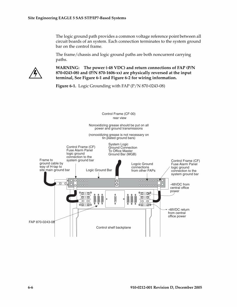
6-6 910-0212-001 Revision D, December 2005
Site Engineering EAGLE 5 SAS STP/IP7-Based Systems
The logic ground path provides a common voltage reference point between all circuit boards of an system. Each connection terminates to the system ground bar on the control frame.
The frame/chassis and logic ground paths are both noncurrent carrying paths.
WARNING: The power (-48 VDC) and return connections of FAP (P/N 870-0243-08) and (P/N 870-1606-xx) are physically reversed at the input terminal, See Figure 6-1 and Figure 6-2 for wiring information.
Figure 6-1. Logic Grounding with FAP (P/N 870-0243-08)
Logic Ground Bar
Control Frame (CF-00) rear view
Nonoxidizing grease should be put on allpower and ground transmissions
(nonoxidizing grease is not necessary ontin plated ground bars)
Control shelf backplane
Frame toground cable byway of H-tap tosite main ground bar
-48VDC fromcentral officepower
-48VDC returnfrom centraloffice power
Control Frame (CF)Fuse Alarm Panellogic groundconnection to thesystem ground bar Control Frame (CF)
Fuse Alarm Panellogic groundconnection to thesystem ground bar
FAP 870-0243-08
Logcic Groundconnectionsfrom other FAPs
System LogicGround ConnectionTo Office MasterGround Bar (MGB)

Site Engineering EAGLE 5 SAS
910-0212-001 Revision D, December 2005 6-7
Figure 6-2. Logic Grounding with FAP (P/N 870-1606-xx/870-2320-xx)
The doors installed are grounded to the frame through a double lug ground wire (see Figure 6-3) and through a screw-down latch.
Figure 6-3. Door Grounding
fap frnt rear 1606
B-side A-sideRearview
AB
P1 P2 P3 P1 P2 P3
12 18 19 20
12 1819 20
12 18 1920
12 181920
-48V
RET
LOGICGND
B A
-48V
RET
LOGICGND
ALARM INTERFACE
-48V
Return
Chassisground
-48V
Fuse positionnumbers
Fuse positionnumbers
12 1819 20 12 1819 20TORQUE TO
25 IN-LBSTORQUE TO
25 IN-LBS
E30 d
oor gro
und
*%%��+�%!&(
6-8 910-0212-001 Revision D, December 2005
Site Engineering EAGLE 5 SAS STP/IP7-Based Systems
Power Requirements
Each frame requires that power be provided from two fuses/breakers at –48VDC. Additional peripherals that require alternating current (for example but not limited to, terminals, printers, and modems) must be compatible with the system and have a separate ground from the frames.
Each frame is divided into A and B power buses. In the event of loss of power on one of the buses, the other bus must be able to supply current for the entire frame. Therefore, each bus requires wiring sized to handle up to the maximum amps at –48VDC, with a maximum voltage drop of 0.6 volts. To meet this specification you must:
• For new installations of Control and Extension Frames (as of Release 34.0) use 60 amp breakers (see note), the EOAP Frames use 30 amp breakers, the ELAP frames use 30 amp and 60 amp breakers, and the EPAP frames use 30 amp breakers. Local Alarms for the Frame’s Power Distribution System are provided at each frame.
NOTE: Existing frames that are fused at 40 amps can be upgraded to support 60 amps with a FAP upgrade kit. 60 amps is required for frames that contain HC-MIMs.
• Use #6, two-hole, #10 Bolt, 5/8" on center lug with windows (P/N 502-0085-01) for fuse and alarm panel connectors.
NOTE: If breakers are tripped by an overload, they must be switched completely OFF and then ON to reset.
Populating the System
The number of frames, shelves, and modules needed to populate the system can be determined using the following procedures.
Link Interface Module (LIM) Requirements
Procedure – Link Interface Module Requirements
Total the following items to determine LIM requirements; any fractional items should be rounded up to the next whole number.

Site Engineering EAGLE 5 SAS
910-0212-001 Revision D, December 2005 6-9
Low-Speed Link Interface module (LSLIM):
• SS7 DSOA links/2
• SS7 OCU links/2
• SS7 V.35 links/2
• E1 links/2
• X.25 DSOA links
• X.25 OCU links
----------------------------
+1 ILA +1= total LIM requirements
High Speed Link Interface Module (HSLIM):
• SS7 ATM/T1 links
----------------------------
+1= total LIM requirements
Cards Type Requirements for SCCP Application with Group Ticket Voucher (TVG)
Group Ticket Voucher (TVG) allows the EAGLE 5 SAS STP to assign transactions to available resources. With TVG, EAGLE 5 SAS STP provisioning for SCCP cards is defined on a transactions per second (TPS) basis, where the desired TPS of the system will be determined by the amount of TSM and DSM cards configured. For example, if the user needs 10,000 TPS (regardless of the number of links) 12 (10,000/850) TSM cards or six (10,000 / 1700) DSM cards should be configured. TPS values for individual LIM card types are.
• 53 TPS for low-speed links
• 480 TPS for ATM links
• 1000 TPS for IPMLIM links

6-10 910-0212-001 Revision D, December 2005
Site Engineering EAGLE 5 SAS STP/IP7-Based Systems
The number of TVG requests that can be made per card is a function of the number of cards in the system, and decreases as the number of active cards increase. It is approximately 1/(Nx10-6) for N cards. For a system with 250 cards, it is limited to about 3300 TVG requests/second. With the introduction of the MPL card, in a non-HMUX system, there cannot be more than 131 cards (MPL, SCCP, and SLAN) in the system.
NOTE 1: It is Tekelec's recommendation that cards running the SCCP application be uniformly distributed in the EAGLE 5 SAS STP to provide a more even SCCP load distribution. During normal operation unevenly distributed SCCP cards in an EAGLE STP would not have any network or system impacts. However, should a particular SCCP card database(s) become corrupted, inconsistent, or at different levels, depending on the amount of service provided by that card and the extent of the database issue, network impacts can occur.
NOTE 2: The MPL card improves the functionality of SS7 routing within the EAGLE by increasing the number of SS7 links the EAGLE can handle for each LIM card. This allows the EAGLE to interact in larger SS7 networks as well as decreasing the size of an EAGLE (for example, previously 250 cards would be required to support 500 links, now only 63 MPL cards are required).
Database Communications Module (DCM) and Double-Slot Enhanced DCM (EDCM)
The Database Communications Module (DCM) (P/N 870-1671-xx or P/N 870-1945-01) can be used in EAGLE 5 SAS STP or IP7 GW systems). The Double Slot EDCM (P/N 870-2197-01) is used in IP7 SG release 4.0 systems and later. Both cards provide the following functions for the systems:
• Signaling Transfer Point, Local Area Network (SLAN) function, port to DCM or Double Slot EDCM
• Enhanced Bulk Download
• GR-376 (EAGLE 5 SAS STP systems only)
NOTE: The DCM card requires two slots for mounting and must be assigned to an odd numbered slot with the next even slot left open on EAGLE 5 SAS STP systems. IP7 SG systems do not restrict slot provisioning for DCM or EDCM cards.
The DCM card is compatible with EAGLE 5 SAS STP control shelf backplanes P/N 850-0330-03/04/05/06 and extension backplanes P/N 850-0356-01/02/03/04. The Double-Slot EDCM is compatible with IP7 SG control shelf backplanes P/N 850-0330-03/04/05 and extension shelf backplanes P/N 850-0356-01/02/03. These cards are provisioned in pairs for redundancy with mated pairs mounted in shelves. Size places some restrictions on the placement of DCM or Double-Slot EDCM cards.
Site Engineering EAGLE 5 SAS
910-0212-001 Revision D, December 2005 6-11
The DCM cards require a unique cable interface that is not compatible with current LIM cables on a fully wired but unequipped shelf. The location of the DCM cards must be to odd numbered slots, requiring two slots with the next higher-numbered even slots left open.
Cabling DCM and Double-Slot EDCM Cards
The DCM and EDCM support only Category 5 (100-Ohm) shielded twisted pair cables. In order to meet Electromagnetic Interference (EMI) requirements, the DCM or Double-Slot EDCM may require a point-to-point connection or a connection to a hub/router. This must be identified to the customer who may be preparing the location. See Figure 6-4 "Database Communications Module Cabling in System" on page 6-12, for cable types and part numbers.
The maximum cable length has not been determined but will be less than 100 meters.
Three specific DCM cables are required:
• Customer patch panel “straight through” (P/N 830-0788-xx)
• Customer patch panel “crossover” (P/N 830-0789-xx)
• 100-BASE TX interface to unterminated (P/N 830-0711-xx)
Hardware
The systems support a maximum of six DCMs or Double-Slot EDCMs for Internet Protocol Link Interface Module (IP LIM) application.
If more than one DCM or Double-Slot EDCM is provisioned, each must be powered from different fuse positions and distributed evenly among “A” and “B” power feeds.
CAUTION: In EAGLE 5 SAS STP systems care must be taken to be sure the DCM card is inserted into the correct odd numbered slots. In IP7 SG systems there is no slot provisioning requirements. Cards may be provisioned in any slot where they physically fit except for the HMUX and MAS dedicated card slots.
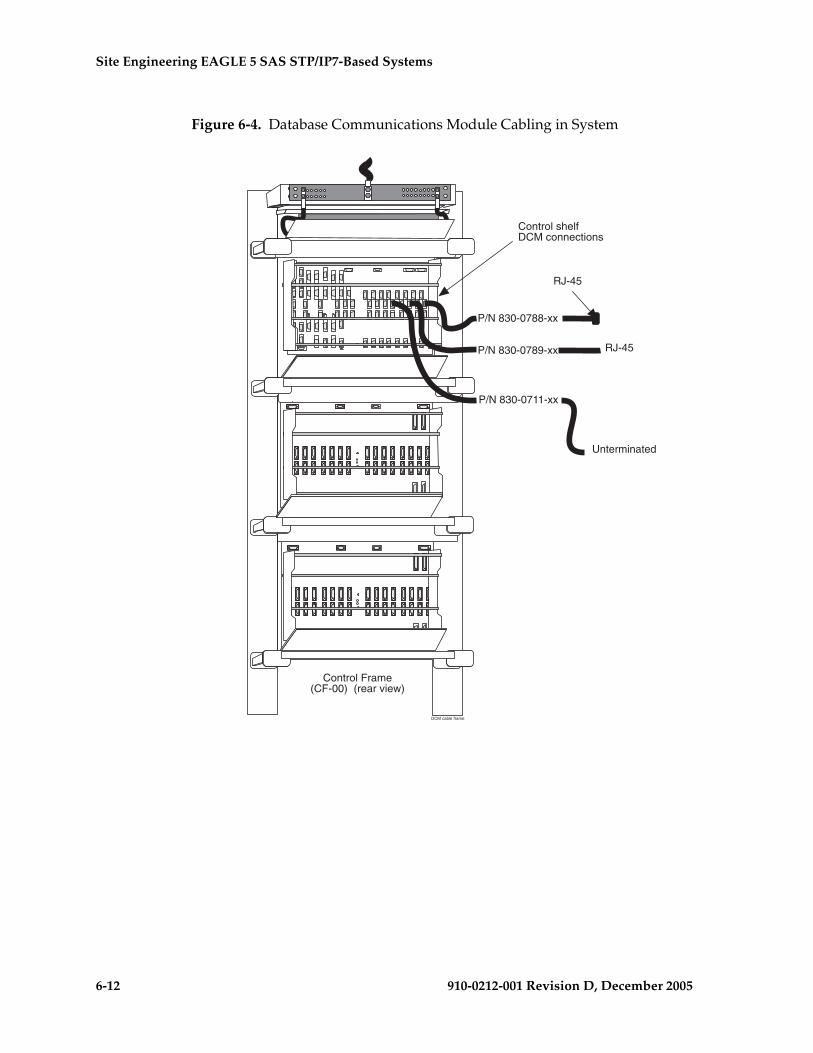
6-12 910-0212-001 Revision D, December 2005
Site Engineering EAGLE 5 SAS STP/IP7-Based Systems
Figure 6-4. Database Communications Module Cabling in System
Control Frame(CF-00) (rear view)
DCM cable frame
Control shelfDCM connections
P/N 830-0788-xx
P/N 830-0789-xx
P/N 830-0711-xx
RJ-45
RJ-45
Unterminated

Site Engineering EAGLE 5 SAS
910-0212-001 Revision D, December 2005 6-13
Single-Slot EDCM and EDCM-A (IP7 SG 5.0 ; EAGLE 5 SAS 28.1)
The Single-Slot Enhanced Data Communications Module EDCM (P/N 870-2372-01) and EDCM-A (P/N 870-2508-01) require only a single frame slot. It can be placed into any slot, odd or even, which has been provisioned for an Enhanced Data Communications Module (EDCM). Otherwise it duplicates the performance of the Double-Slot EDCM.
NOTE: Cards may be provisioned in any slot where they physically fit except for the HMUX and MAS dedicated card slots.
The following cards can be configured from the single-slot EDCM and have these provisioning requirements:
• Sentinel Transport Cards (STC) can be provisioned in any slot to support the Integrated Sentinel. Only three STC cards may be provisioned on each shelf.
• General Purpose Service Modules (GPSM-II) cards can be provisioned in card slots (1113 and 1115).
• Measurements Collection and Polling Modules (MCPM) can be provisioned an any slot.
Application Services Module Requirements
The following rules apply to calculating Application Service Module (ASM) card numbers for applications, where Gateway Screening (GWS) is present in a Signaling Connection Control Part (SCCP) system.
NOTE: Beginning with EAGLE release 31.6 ASM cards will no longer be supported and must be replaced by TSM cards. SCCP, GTT, GWS, and GLS functions will be provided by TSM cards. Application Services Module numbers for Gateway Screening. For more information, see “Application Service Module” on page 3-88.
If the Gateway Screening (GWS) feature is present, two ASMs are required.
ASM Numbers for SCCP
To calculate the number of required ASMs in an SCCP system, use the following formula:
LSLIM N = maximum of (LIMs ÷ 16) or (translations/seconds ÷ 850)
HSLIM N = maximum of (LIM ATM÷ 2) or (translations/seconds ÷ 850)
Both high speed links and low speed links may exist in the same system.
ASMs =LSLIM N + HSLIM N+1

6-14 910-0212-001 Revision D, December 2005
Site Engineering EAGLE 5 SAS STP/IP7-Based Systems
Application Communications Module Requirements
Procedure – Application Communications Module Requirements
1. If the Signal Transfer Point (STP), Local Area Network (SLAN) feature is not required for this system, no ACMs are needed.
2. If the Signal Transfer Point (STP), Local Area Network (SLAN) feature is required for this system, one ACM is required for each 30 LIMs in the system (refer to the previous procedure) plus one spare ACM. (LIMs) /30 round up to next whole number +1=ACM needed in a system.
Procedure – Translations Services Module for Local Number Portability
Each Translations Service Module (TSM) is capable of 850 translations per second for up to 16 LIMs. For reliability, the number of TSMs equipped should be “N + 1,” where “N” represents at least one TSM for each 16 LIMs, or at most 25 TSMs to achieve a full 20 (400 translations per second) per system node.
To calculate N (number of TSMs):
1. Calculate the number of TSMs per 16 LIMs and add one.
2. Calculate the number of TSMs per 2 LIM ATMs and add one.
3. Choose whichever number is the greater of the two calculations (N+1)
OAP and Embedded OAP
These rules apply to populating the OAP or EOAP for Local Number Portability (LNP):
• For LNP, two OAPs or a dual EOAP is required and can be installed in the same OAP frame
• If an OAP frame with two OAPS already exists for Signaling Engineering and Administration System (SEAS), then it will be used for LNP
• If an OAP frame with only one OAP or EOAP already exists for SEAS, then one additional OAP or EOAP will be required for LNP
910-0212-001 Revision D, December 2005 A-1
A
Hardware Baselines
Baseline Tables
The following tables list the configurable hardware components for each release. A bold X in a table cell indicates the component listed on the left is valid for the release indicated at the top of the column. To obtain configuration information about hardware and release compatibility for each release use:
Eagle STP
• Release 25.0 through 26.05 in Table A-1, “Hardware Baseline EAGLE Releases 25.0 through 26.05,” on page A-2.
• Release 26.1 through 29.1 in Table A-2, “Hardware Baseline EAGLE Releases 26.1 through 29.1,” on page A-7
• Release 30.0 through 34.0 in Table A-3, “Hardware Baseline EAGLE Release 30.0 through 34.0,” on page A-13
• EAGLE E1/T1 MIM Support in Table A-4, “E1/T1 MIM Support by Release,” on page A-20
• EAGLE Cable Assemblies and Adapters:
– Table A-5, “E1 Cable Assemblies,” on page A-20
– Table A-6, “T1 MIM LIM Cable Assemblies,” on page A-20
– Table A-7, “Terminal/Printer Cables and Adapters,” on page A-21
– Table A-8, “Modem Cables and Adapters,” on page A-21
– Table A-9, “Tekelec 1000 Site Specific Cables,” on page A-21
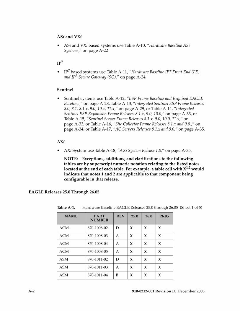
A-2 910-0212-001 Revision D, December 2005
ASi and VXi
• ASi and VXi based systems use Table A-10, “Hardware Baseline ASi Systems,” on page A-22
IP7
• IP7 based systems use Table A-11, “Hardware Baseline IP7 Front End (FE) and IP7 Secure Gateway (SG),” on page A-24
Sentinel
• Sentinel systems use Table A-12, “ESP Frame Baseline and Required EAGLE Baseline.,” on page A-28, Table A-13, “Integrated Sentinel ESP Frame Releases 8.0, 8.1, 8.1.x, 9.0, 10.x, 11.x,” on page A-29, or Table A-14, “Integrated Sentinel ESP Expansion Frame Releases 8.1.x, 9.0, 10.0,” on page A-33, or Table A-15, “Sentinel Server Frame Releases 8.1.x, 9.0, 10.0, 11.x,” on page A-33, or Table A-16, “Site Collector Frame Releases 8.1.x and 9.0.,” on page A-34, or Table A-17, “AC Servers Releases 8.1.x and 9.0,” on page A-35.
AXi
• AXi System use Table A-18, “AXi System Release 1.0,” on page A-35.
NOTE: Exceptions, additions, and clarifications to the following tables are by superscript numeric notation relating to the listed notes located at the end of each table. For example, a table cell with X1,2 would indicate that notes 1 and 2 are applicable to that component being configurable in that release.
EAGLE Releases 25.0 Through 26.05
Table A-1. Hardware Baseline EAGLE Releases 25.0 through 26.05 (Sheet 1 of 5)
NAME PART NUMBER
REV 25.0 26.0 26.05
ACM 870-1008-02 D X X X
ACM 870-1008-03 A X X X
ACM 870-1008-04 A X X X
ACM 870-1008-05 A X X X
ASM 870-1011-02 D X X X
ASM 870-1011-03 A X X X
ASM 870-1011-04 B X X X
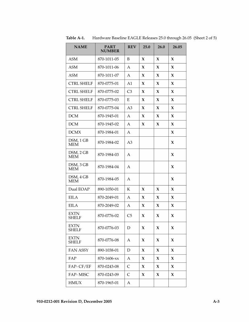
910-0212-001 Revision D, December 2005 A-3
ASM 870-1011-05 B X X X
ASM 870-1011-06 A X X X
ASM 870-1011-07 A X X X
CTRL SHELF 870-0775-01 A1 X X X
CTRL SHELF 870-0775-02 C3 X X X
CTRL SHELF 870-0775-03 E X X X
CTRL SHELF 870-0775-04 A3 X X X
DCM 870-1945-01 A X X X
DCM 870-1945-02 A X X X
DCMX 870-1984-01 A X
DSM, 1 GB MEM 870-1984-02 A3 X
DSM, 2 GB MEM 870-1984-03 A X
DSM, 3 GB MEM 870-1984-04 A X
DSM, 4 GB MEM 870-1984-05 A X
Dual EOAP 890-1050-01 K X X X
EILA 870-2049-01 A X X X
EILA 870-2049-02 A X X X
EXTN SHELF 870-0776-02 C5 X X X
EXTN SHELF 870-0776-03 D X X X
EXTN SHELF 870-0776-08 A X X X
FAN ASSY 890-1038-01 D X X X
FAP 870-1606-xx A X X X
FAP- CF/EF 870-0243-08 C X X X
FAP- MISC 870-0243-09 C X X X
HMUX 870-1965-01 A
Table A-1. Hardware Baseline EAGLE Releases 25.0 through 26.05 (Sheet 2 of 5)
NAME PART NUMBER
REV 25.0 26.0 26.05
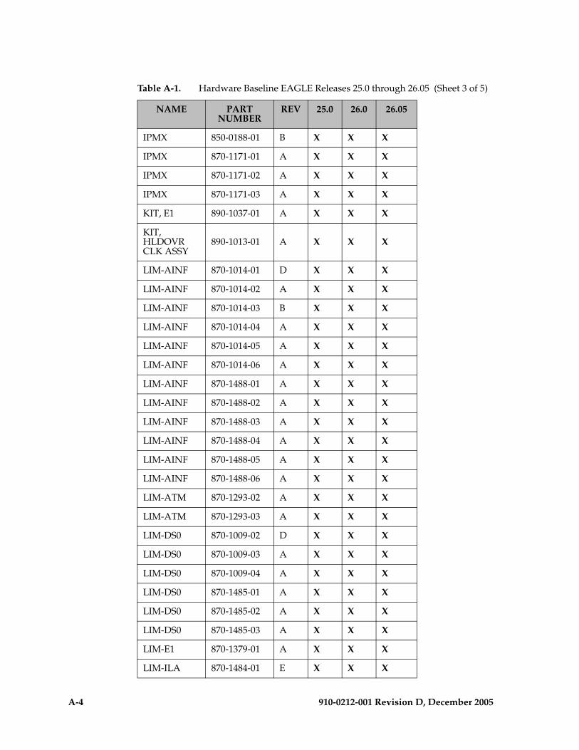
A-4 910-0212-001 Revision D, December 2005
IPMX 850-0188-01 B X X X
IPMX 870-1171-01 A X X X
IPMX 870-1171-02 A X X X
IPMX 870-1171-03 A X X X
KIT, E1 890-1037-01 A X X X
KIT, HLDOVR CLK ASSY
890-1013-01 A X X X
LIM-AINF 870-1014-01 D X X X
LIM-AINF 870-1014-02 A X X X
LIM-AINF 870-1014-03 B X X X
LIM-AINF 870-1014-04 A X X X
LIM-AINF 870-1014-05 A X X X
LIM-AINF 870-1014-06 A X X X
LIM-AINF 870-1488-01 A X X X
LIM-AINF 870-1488-02 A X X X
LIM-AINF 870-1488-03 A X X X
LIM-AINF 870-1488-04 A X X X
LIM-AINF 870-1488-05 A X X X
LIM-AINF 870-1488-06 A X X X
LIM-ATM 870-1293-02 A X X X
LIM-ATM 870-1293-03 A X X X
LIM-DS0 870-1009-02 D X X X
LIM-DS0 870-1009-03 A X X X
LIM-DS0 870-1009-04 A X X X
LIM-DS0 870-1485-01 A X X X
LIM-DS0 870-1485-02 A X X X
LIM-DS0 870-1485-03 A X X X
LIM-E1 870-1379-01 A X X X
LIM-ILA 870-1484-01 E X X X
Table A-1. Hardware Baseline EAGLE Releases 25.0 through 26.05 (Sheet 3 of 5)
NAME PART NUMBER
REV 25.0 26.0 26.05

910-0212-001 Revision D, December 2005 A-5
LIM-ILA 870-1484-02 C X X X
LIM-OCU 870-1010-03 D X X X
LIM-OCU 870-1010-04 A X X X
LIM-OCU 870-1010-05 A X X X
LIM-OCU 870-1486-02 A X X X
LIM-OCU 870-1486-03 A X X X
LIM-OCU 870-1486-04 A X X X
LIM-V.35 870-1012-02 D X X X
LIM-V.35 870-1012-03 A X X X
LIM-V.35 870-1012-04 A X X X
LIM-V.35 870-1487-01 A X X X
LIM-V.35 870-1487-02 A X X X
LIM-V.35 870-1487-03 A X X X
MCAP 870-1013-08 A X
MCAP 870-1013-09 A X
MCAP 870-1013-10 A X
MCAP 870-1013-11 A X
MCAP-256 870-1307-04 A X X X
MCAP-256 870-1307-05 A X X X
MCAP-256 870-1307-06 A X X
MDAL 870-0773-04 B X X X
MDAL 870-0773-05 A X X X
MDAL 870-0773-06 A X X X
TDM 870-0774-04 E X X X
TDM 870-0774-05 D X X X
TDM 870-0774-06 A X X X
TDM 870-0774-07 A X X X
TDM 870-0774-08 A X X X
TDM-E1 870-1442-01 A X X X
Table A-1. Hardware Baseline EAGLE Releases 25.0 through 26.05 (Sheet 4 of 5)
NAME PART NUMBER
REV 25.0 26.0 26.05

A-6 910-0212-001 Revision D, December 2005
TSM-1024 870-1292-02 A X X X
TSM-1024 870-1292-03 A X X X
TSM-256 870-1289-02 A X X X
TSM-256 870-1289-03 A X X X
TSM-512 870-1290-02 A X X X
TSM-512 870-1290-03 A X X X
TSM-768 870-1291-02 A X X X
TSM-768 870-1291-03 A X X X
Table A-1. Hardware Baseline EAGLE Releases 25.0 through 26.05 (Sheet 5 of 5)
NAME PART NUMBER
REV 25.0 26.0 26.05
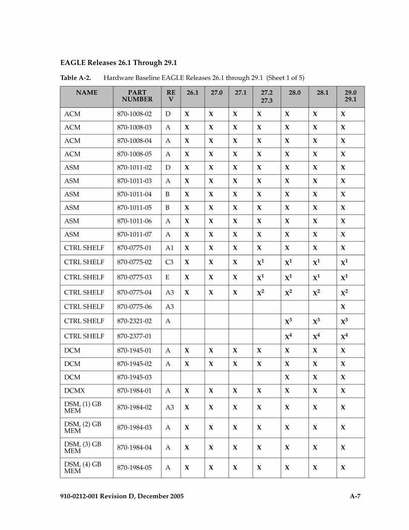
910-0212-001 Revision D, December 2005 A-7
EAGLE Releases 26.1 Through 29.1
Table A-2. Hardware Baseline EAGLE Releases 26.1 through 29.1 (Sheet 1 of 5)
NAME PART NUMBER
REV
26.1 27.0 27.1 27.227.3
28.0 28.1 29.0 29.1
ACM 870-1008-02 D X X X X X X X
ACM 870-1008-03 A X X X X X X X
ACM 870-1008-04 A X X X X X X X
ACM 870-1008-05 A X X X X X X X
ASM 870-1011-02 D X X X X X X X
ASM 870-1011-03 A X X X X X X X
ASM 870-1011-04 B X X X X X X X
ASM 870-1011-05 B X X X X X X X
ASM 870-1011-06 A X X X X X X X
ASM 870-1011-07 A X X X X X X X
CTRL SHELF 870-0775-01 A1 X X X X X X X
CTRL SHELF 870-0775-02 C3 X X X X1 X1 X1 X1
CTRL SHELF 870-0775-03 E X X X X1 X1 X1 X1
CTRL SHELF 870-0775-04 A3 X X X X2 X2 X2 X2
CTRL SHELF 870-0775-06 A3 X
CTRL SHELF 870-2321-02 A X3 X3 X3
CTRL SHELF 870-2377-01 X4 X4 X4
DCM 870-1945-01 A X X X X X X X
DCM 870-1945-02 A X X X X X X X
DCM 870-1945-03 X X X
DCMX 870-1984-01 A X X X X X X X
DSM, (1) GB MEM 870-1984-02 A3 X X X X X X X
DSM, (2) GB MEM 870-1984-03 A X X X X X X X
DSM, (3) GB MEM 870-1984-04 A X X X X X X X
DSM, (4) GB MEM 870-1984-05 A X X X X X X X
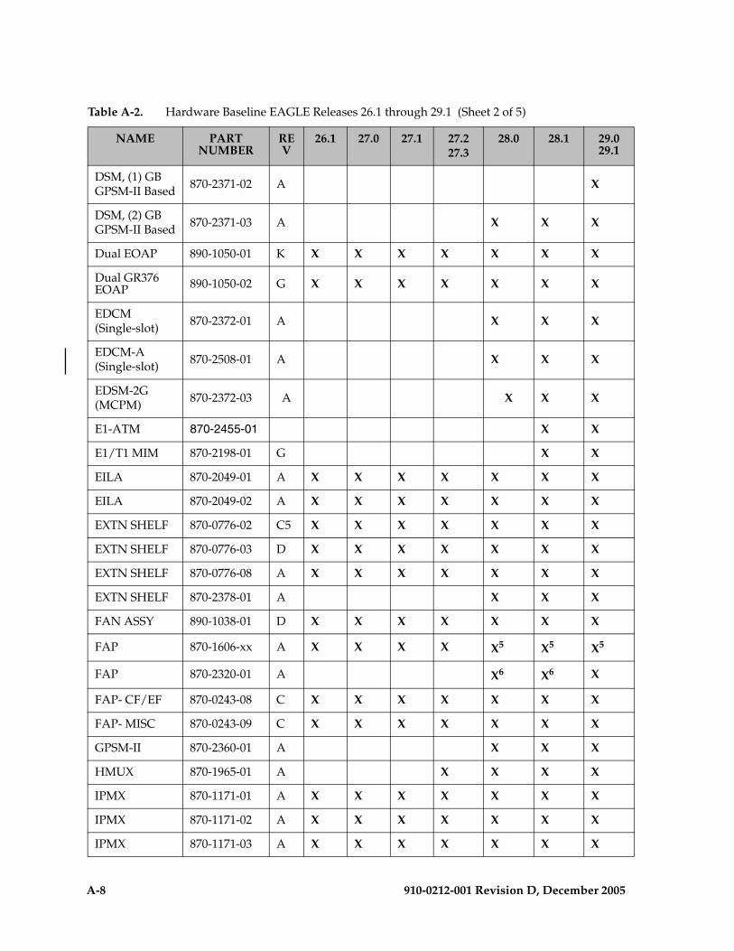
A-8 910-0212-001 Revision D, December 2005
DSM, (1) GBGPSM-II Based 870-2371-02 A X
DSM, (2) GBGPSM-II Based 870-2371-03 A X X X
Dual EOAP 890-1050-01 K X X X X X X X
Dual GR376 EOAP 890-1050-02 G X X X X X X X
EDCM(Single-slot) 870-2372-01 A X X X
EDCM-A(Single-slot) 870-2508-01 A X X X
EDSM-2G(MCPM) 870-2372-03 A X X X
E1-ATM 870-2455-01 X X
E1/T1 MIM 870-2198-01 G X X
EILA 870-2049-01 A X X X X X X X
EILA 870-2049-02 A X X X X X X X
EXTN SHELF 870-0776-02 C5 X X X X X X X
EXTN SHELF 870-0776-03 D X X X X X X X
EXTN SHELF 870-0776-08 A X X X X X X X
EXTN SHELF 870-2378-01 A X X X
FAN ASSY 890-1038-01 D X X X X X X X
FAP 870-1606-xx A X X X X X5 X5 X5
FAP 870-2320-01 A X6 X6 X
FAP- CF/EF 870-0243-08 C X X X X X X X
FAP- MISC 870-0243-09 C X X X X X X X
GPSM-II 870-2360-01 A X X X
HMUX 870-1965-01 A X X X X
IPMX 870-1171-01 A X X X X X X X
IPMX 870-1171-02 A X X X X X X X
IPMX 870-1171-03 A X X X X X X X
Table A-2. Hardware Baseline EAGLE Releases 26.1 through 29.1 (Sheet 2 of 5)
NAME PART NUMBER
REV
26.1 27.0 27.1 27.227.3
28.0 28.1 29.0 29.1

910-0212-001 Revision D, December 2005 A-9
KIT, E1 890-1037-01 A X X X X X X X
KIT, HLDOVR CLK ASSY 890-1013-01 A X X X X X X X
LIM-AINF 870-1014-01 D X X X X X X X
LIM-AINF 870-1014-02 A X X X X X X X
LIM-AINF 870-1014-03 B X X X X X X X
LIM-AINF 870-1014-04 A X X X X X X X
LIM-AINF 870-1014-05 A X X X X X X X
LIM-AINF 870-1014-06 A X X X X X X X
LIM-AINF 870-1488-01 A X X X X X X X
LIM-AINF 870-1488-02 A X X X X X X X
LIM-AINF 870-1488-03 A X X X X X X X
LIM-AINF 870-1488-04 A X X X X X X X
LIM-AINF 870-1488-05 A X X X X X X X
LIM-AINF 870-1488-06 A X X X X X X X
LIM-ATM(1) 4Mb RAM 870-1293-02 A X X X X X X X
LIM-ATM(2) 4Mb RAM 870-1293-03 A X X X X X X X
LIM-ATM 870-1293-06 A X
LIM-ATM 870-1293-07 A X
LIM-DS0 870-1009-02 D X X X X X X X
LIM-DS0 870-1009-03 A X X X X X X X
LIM-DS0 870-1009-04 A X X X X X X X
LIM-DS0 870-1485-01 A X X X X X X X
LIM-DS0 870-1485-02 A X X X X X X X
LIM-DS0 870-1485-03 A X X X X X X X
LIM-E1 870-1379-01 A X X X X X X X
LIM-ILA 870-1484-01 E X X X X X X X
LIM-ILA 870-1484-02 C X X X X X X X
Table A-2. Hardware Baseline EAGLE Releases 26.1 through 29.1 (Sheet 3 of 5)
NAME PART NUMBER
REV
26.1 27.0 27.1 27.227.3
28.0 28.1 29.0 29.1
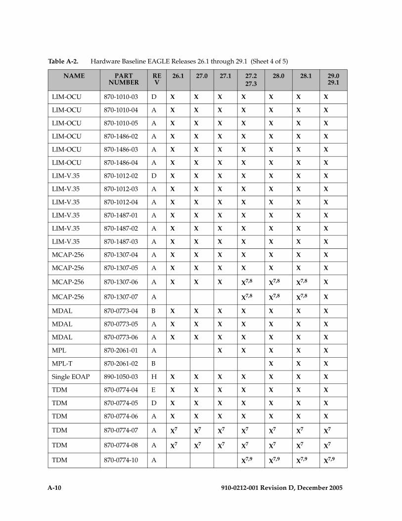
A-10 910-0212-001 Revision D, December 2005
LIM-OCU 870-1010-03 D X X X X X X X
LIM-OCU 870-1010-04 A X X X X X X X
LIM-OCU 870-1010-05 A X X X X X X X
LIM-OCU 870-1486-02 A X X X X X X X
LIM-OCU 870-1486-03 A X X X X X X X
LIM-OCU 870-1486-04 A X X X X X X X
LIM-V.35 870-1012-02 D X X X X X X X
LIM-V.35 870-1012-03 A X X X X X X X
LIM-V.35 870-1012-04 A X X X X X X X
LIM-V.35 870-1487-01 A X X X X X X X
LIM-V.35 870-1487-02 A X X X X X X X
LIM-V.35 870-1487-03 A X X X X X X X
MCAP-256 870-1307-04 A X X X X X X X
MCAP-256 870-1307-05 A X X X X X X X
MCAP-256 870-1307-06 A X X X X7,8 X7,8 X7,8 X
MCAP-256 870-1307-07 A X7,8 X7,8 X7,8 X
MDAL 870-0773-04 B X X X X X X X
MDAL 870-0773-05 A X X X X X X X
MDAL 870-0773-06 A X X X X X X X
MPL 870-2061-01 A X X X X X
MPL-T 870-2061-02 B X X X
Single EOAP 890-1050-03 H X X X X X X X
TDM 870-0774-04 E X X X X X X X
TDM 870-0774-05 D X X X X X X X
TDM 870-0774-06 A X X X X X X X
TDM 870-0774-07 A X7 X7 X7 X7 X7 X7 X7
TDM 870-0774-08 A X7 X7 X7 X7 X7 X7 X7
TDM 870-0774-10 A X7,9 X7,9 X7,9 X7,9
Table A-2. Hardware Baseline EAGLE Releases 26.1 through 29.1 (Sheet 4 of 5)
NAME PART NUMBER
REV
26.1 27.0 27.1 27.227.3
28.0 28.1 29.0 29.1
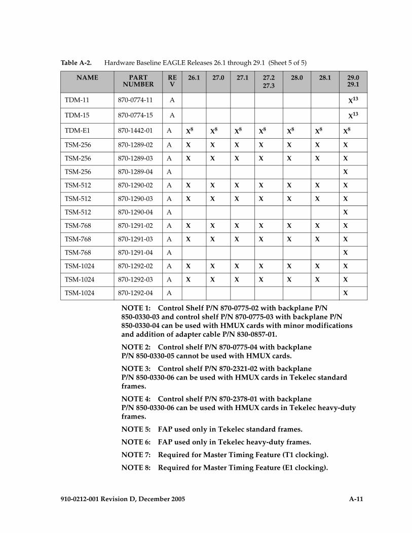
910-0212-001 Revision D, December 2005 A-11
NOTE 1: Control Shelf P/N 870-0775-02 with backplane P/N 850-0330-03 and control shelf P/N 870-0775-03 with backplane P/N 850-0330-04 can be used with HMUX cards with minor modifications and addition of adapter cable P/N 830-0857-01.
NOTE 2: Control shelf P/N 870-0775-04 with backplane P/N 850-0330-05 cannot be used with HMUX cards.
NOTE 3: Control shelf P/N 870-2321-02 with backplane P/N 850-0330-06 can be used with HMUX cards in Tekelec standard frames.
NOTE 4: Control shelf P/N 870-2378-01 with backplane P/N 850-0330-06 can be used with HMUX cards in Tekelec heavy-duty frames.
NOTE 5: FAP used only in Tekelec standard frames.
NOTE 6: FAP used only in Tekelec heavy-duty frames.
NOTE 7: Required for Master Timing Feature (T1 clocking).
NOTE 8: Required for Master Timing Feature (E1 clocking).
TDM-11 870-0774-11 A X13
TDM-15 870-0774-15 A X13
TDM-E1 870-1442-01 A X8 X8 X8 X8 X8 X8 X8
TSM-256 870-1289-02 A X X X X X X X
TSM-256 870-1289-03 A X X X X X X X
TSM-256 870-1289-04 A X
TSM-512 870-1290-02 A X X X X X X X
TSM-512 870-1290-03 A X X X X X X X
TSM-512 870-1290-04 A X
TSM-768 870-1291-02 A X X X X X X X
TSM-768 870-1291-03 A X X X X X X X
TSM-768 870-1291-04 A X
TSM-1024 870-1292-02 A X X X X X X X
TSM-1024 870-1292-03 A X X X X X X X
TSM-1024 870-1292-04 A X
Table A-2. Hardware Baseline EAGLE Releases 26.1 through 29.1 (Sheet 5 of 5)
NAME PART NUMBER
REV
26.1 27.0 27.1 27.227.3
28.0 28.1 29.0 29.1

A-12 910-0212-001 Revision D, December 2005
NOTE 9: Required for HMUX cards.
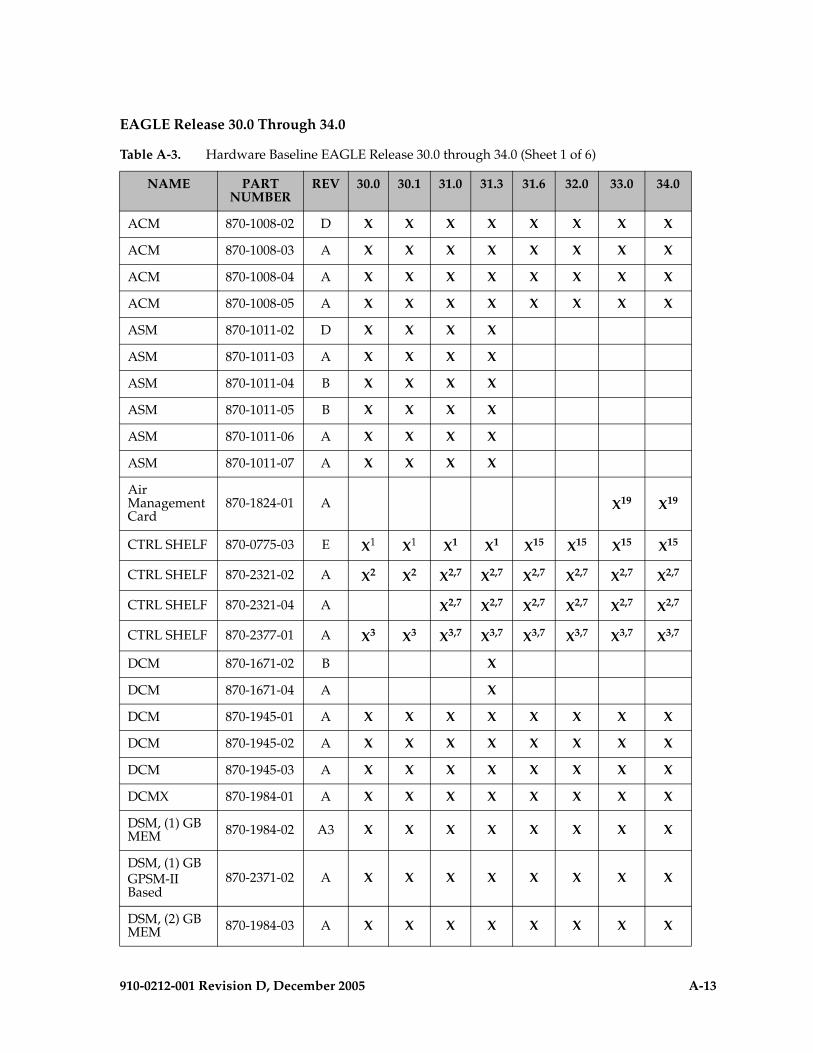
910-0212-001 Revision D, December 2005 A-13
EAGLE Release 30.0 Through 34.0
Table A-3. Hardware Baseline EAGLE Release 30.0 through 34.0 (Sheet 1 of 6)
NAME PART NUMBER
REV 30.0 30.1 31.0 31.3 31.6 32.0 33.0 34.0
ACM 870-1008-02 D X X X X X X X X
ACM 870-1008-03 A X X X X X X X X
ACM 870-1008-04 A X X X X X X X X
ACM 870-1008-05 A X X X X X X X X
ASM 870-1011-02 D X X X X
ASM 870-1011-03 A X X X X
ASM 870-1011-04 B X X X X
ASM 870-1011-05 B X X X X
ASM 870-1011-06 A X X X X
ASM 870-1011-07 A X X X X
Air Management Card
870-1824-01 A X19 X19
CTRL SHELF 870-0775-03 E X1 X1 X1 X1 X15 X15 X15 X15
CTRL SHELF 870-2321-02 A X2 X2 X2,7 X2,7 X2,7 X2,7 X2,7 X2,7
CTRL SHELF 870-2321-04 A X2,7 X2,7 X2,7 X2,7 X2,7 X2,7
CTRL SHELF 870-2377-01 A X3 X3 X3,7 X3,7 X3,7 X3,7 X3,7 X3,7
DCM 870-1671-02 B X
DCM 870-1671-04 A X
DCM 870-1945-01 A X X X X X X X X
DCM 870-1945-02 A X X X X X X X X
DCM 870-1945-03 A X X X X X X X X
DCMX 870-1984-01 A X X X X X X X X
DSM, (1) GB MEM 870-1984-02 A3 X X X X X X X X
DSM, (1) GBGPSM-II Based
870-2371-02 A X X X X X X X X
DSM, (2) GB MEM 870-1984-03 A X X X X X X X X
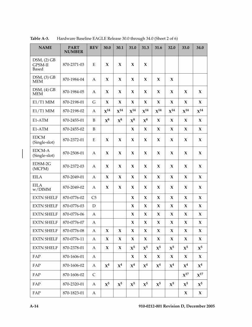
A-14 910-0212-001 Revision D, December 2005
DSM, (2) GBGPSM-II Based
870-2371-03 E X X X X
DSM, (3) GB MEM 870-1984-04 A X X X X X X
DSM, (4) GB MEM 870-1984-05 A X X X X X X X X
E1/T1 MIM 870-2198-01 G X X X X X X X X
E1/T1 MIM 870-2198-02 A X14 X14 X14 X14 X14 X14 X14 X14
E1-ATM 870-2455-01 B X8 X8 X8 X8 X X X X
E1-ATM 870-2455-02 B X X X X X X
EDCM(Single-slot) 870-2372-01 E X X X X X X X X
EDCM-A(Single-slot) 870-2508-01 A X X X X X X X X
EDSM-2G(MCPM) 870-2372-03 A X X X X X X X X
EILA 870-2049-01 A X X X X X X X X
EILA w/DIMM 870-2049-02 A X X X X X X X X
EXTN SHELF 870-0776-02 C5 X X X X X X
EXTN SHELF 870-0776-03 D X X X X X X
EXTN SHELF 870-0776-06 A X X X X X X
EXTN SHELF 870-0776-07 A X X X X X X
EXTN SHELF 870-0776-08 A X X X X X X X X
EXTN SHELF 870-0776-11 A X X X X X X X X
EXTN SHELF 870-2378-01 A X X X5 X5 X5 X5 X5 X5
FAP 870-1606-01 A X X X X X X
FAP 870-1606-02 A X4 X4 X4 X4 X4 X4 X4 X4
FAP 870-1606-02 C X17 X17
FAP 870-2320-01 A X5 X5 X5 X5 X5 X5 X5 X5
FAP 870-1823-01 A X X
Table A-3. Hardware Baseline EAGLE Release 30.0 through 34.0 (Sheet 2 of 6)
NAME PART NUMBER
REV 30.0 30.1 31.0 31.3 31.6 32.0 33.0 34.0
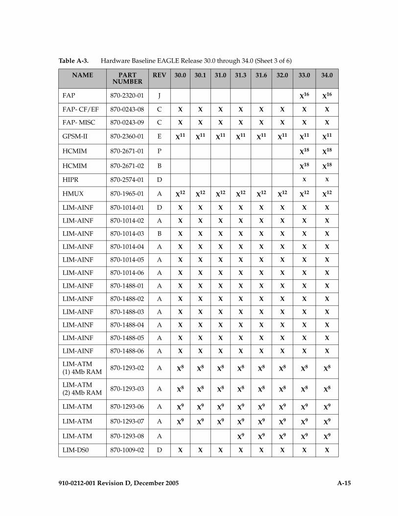
910-0212-001 Revision D, December 2005 A-15
FAP 870-2320-01 J X16 X16
FAP- CF/EF 870-0243-08 C X X X X X X X X
FAP- MISC 870-0243-09 C X X X X X X X X
GPSM-II 870-2360-01 E X11 X11 X11 X11 X11 X11 X11 X11
HCMIM 870-2671-01 P X18 X18
HCMIM 870-2671-02 B X18 X18
HIPR 870-2574-01 D X X
HMUX 870-1965-01 A X12 X12 X12 X12 X12 X12 X12 X12
LIM-AINF 870-1014-01 D X X X X X X X X
LIM-AINF 870-1014-02 A X X X X X X X X
LIM-AINF 870-1014-03 B X X X X X X X X
LIM-AINF 870-1014-04 A X X X X X X X X
LIM-AINF 870-1014-05 A X X X X X X X X
LIM-AINF 870-1014-06 A X X X X X X X X
LIM-AINF 870-1488-01 A X X X X X X X X
LIM-AINF 870-1488-02 A X X X X X X X X
LIM-AINF 870-1488-03 A X X X X X X X X
LIM-AINF 870-1488-04 A X X X X X X X X
LIM-AINF 870-1488-05 A X X X X X X X X
LIM-AINF 870-1488-06 A X X X X X X X X
LIM-ATM(1) 4Mb RAM 870-1293-02 A X8 X8 X8 X8 X8 X8 X8 X8
LIM-ATM(2) 4Mb RAM 870-1293-03 A X8 X8 X8 X8 X8 X8 X8 X8
LIM-ATM 870-1293-06 A X9 X9 X9 X9 X9 X9 X9 X9
LIM-ATM 870-1293-07 A X9 X9 X9 X9 X9 X9 X9 X9
LIM-ATM 870-1293-08 A X9 X9 X9 X9 X9
LIM-DS0 870-1009-02 D X X X X X X X X
Table A-3. Hardware Baseline EAGLE Release 30.0 through 34.0 (Sheet 3 of 6)
NAME PART NUMBER
REV 30.0 30.1 31.0 31.3 31.6 32.0 33.0 34.0

A-16 910-0212-001 Revision D, December 2005
LIM-DS0 870-1009-03 A X X X X X X X X
LIM-DS0 870-1009-04 A X X X X X X X X
LIM-DS0 870-1485-01 A X X X X X X X X
LIM-DS0 870-1485-02 A X X X X X X X X
LIM-DS0 870-1485-03 A X X X X X X X X
LIM-E1 870-1379-01 A X X X X X X X X
LIM-ILA 870-1484-01 E X X X X X X X X
LIM-ILA 870-1484-02 C X X X X X X X X
LIM-OCU 870-1010-03 D X X X X X X X X
LIM-OCU 870-1010-04 A X X X X X X X X
LIM-OCU 870-1010-05 A X X X X X X X X
LIM-OCU 870-1486-02 A X X X X X X X X
LIM-OCU 870-1486-03 A X X X X X X X X
LIM-OCU 870-1486-04 A X X X X X X X X
LIM-V.35 870-1012-02 D X X X X X X X X
LIM-V.35 870-1012-03 A X X X X X X X X
LIM-V.35 870-1012-04 A X X X X X X X X
LIM-V.35 870-1487-01 A X X X X X X X X
LIM-V.35 870-1487-02 A X X X X X X X X
LIM-V.35 870-1487-03 A X X X X X X X X
MDAL 870-0773-04 B X X X X X X X X
MDAL 870-0773-05 A X X X X X X X X
MDAL 870-0773-06 A X X X X X X X X
MDAL 870-0773-08 A X X X X X X
MPL 870-2061-01 A X X X X X X X X
MPL-T 870-2061-02 B X X X X X X X X
TDM-10 870-0774-10 A X6,7
,13X6,7,
13X6,7
,13X6,7,
13X6,7,
13X6,7,
13X6,7,1
3X6,7,1
3
TDM-11 870-0774-11 A X13 X13 X13 X13 X13 X13 X13 X13
Table A-3. Hardware Baseline EAGLE Release 30.0 through 34.0 (Sheet 4 of 6)
NAME PART NUMBER
REV 30.0 30.1 31.0 31.3 31.6 32.0 33.0 34.0

910-0212-001 Revision D, December 2005 A-17
TDM-15 870-0774-15 A X13 X13 X13 X13 X13 X13 X13 X13
TSM-256 870-1289-02 A X X X X X X X X
TSM-256 870-1289-03 A X X X X X X X X
TSM-256 870-1289-04 A X X X X X X X X
TSM-512 870-1290-02 A X X X X X X X X
TSM-512 870-1290-03 A X X X X X X X X
TSM-512 870-1290-04 A X X X X X X X X
TSM-768 870-1291-02 A X X X X X X X X
TSM-768 870-1291-03 A X X X X X X X X
TSM-768 870-1291-04 A X X X X X X X X
TSM-1024 870-1292-02 A X X X X X X X X
TSM-1024 870-1292-03 A X X X X X X X X
TSM-1024 870-1292-04 A X X X X X X X X
Dual EOAP 890-1050-01 K X X X X X X X X
Dual GR376 EOAP 890-1050-02 G X X X X X X X X
Single EOAP 890-1050-03 H X X X X X X X X
FAN ASSY 890-1038-01 D X X X X X X X X
FAN ASSY 890-0001-01 A X20 X20
KIT, E1 890-1037-01 A X X X X X X X X
KIT, HLDOVR CLK ASSY
890-1013-01 A X X X X X X X X
MPS in Heavy Duty Frame
890-1801-01 E X X X X X X
Tekelec 1000 870-2640-01 F X X X X X X
Tekelec 1100 870-2754-02 P X21
MPS Netra-to-Tekelec 1000 Field Upgrade Kit
870-2735-01 A X X X X X X
Table A-3. Hardware Baseline EAGLE Release 30.0 through 34.0 (Sheet 5 of 6)
NAME PART NUMBER
REV 30.0 30.1 31.0 31.3 31.6 32.0 33.0 34.0

A-18 910-0212-001 Revision D, December 2005
NOTE 1: Control shelf P/N 870-0775-03 with backplane P/N 850-0330-04 can be used with minor modifications and addition of adapter cable P/N 830-0857-01.
NOTE 2: Control shelf P/N 870-2321-02 with backplane P/N 850-0330-06 can be used with HMUX cards in Tekelec standard frames.
NOTE 3: Control shelf P/N 870-2377-01 with backplane P/N 850-0330-06 can be used in Tekelec heavy-duty frames.
NOTE 4: Required for Tekelec standard frames. Rev. C required for HCMIM shelves.
NOTE 5: Required for Tekelec heavy-duty frames. Rev. J required for HCMIM shelves.
NOTE 6: Required for Master Timing Feature (T1 clocking).
NOTE 7: Required for HMUX cards.
NOTE 8: Uses HCAP (P/N 850-0419-xx) main assembly board
NOTE 9: Uses HCAP-T (P/N 850-0615-xx) main assembly boards
MPS RAM and CPU Upgrade Kit (two for each frame)
870-2669-02 A X X X X
MPSW O/RAIDS
890-1374-03 E X
MPSW O/RAIDS 890-1374-04 E X
MPSW / 1 GB RAM 890-1374-05 A X
MPSW / 2 GB RAM 890-1374-06 A X X X X X X X X
Table A-3. Hardware Baseline EAGLE Release 30.0 through 34.0 (Sheet 6 of 6)
NAME PART NUMBER
REV 30.0 30.1 31.0 31.3 31.6 32.0 33.0 34.0
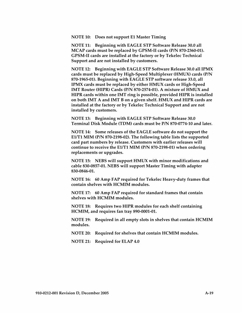
910-0212-001 Revision D, December 2005 A-19
NOTE 10: Does not support E1 Master Timing
NOTE 11: Beginning with EAGLE STP Software Release 30.0 all MCAP cards must be replaced by GPSM-II cards (P/N 870-2360-01). GPSM-II cards are installed at the factory or by Tekelec Technical Support and are not installed by customers.
NOTE 12: Beginning with EAGLE STP Software Release 30.0 all IPMX cards must be replaced by High-Speed Multiplexer (HMUX) cards (P/N 870-1965-01). Beginning with EAGLE STP software release 33.0, all IPMX cards must be replaced by either HMUX cards or High-Speed IMT Router (HIPR) Cards (P/N 870-2574-01). A mixture of HMUX and HIPR cards within one IMT ring is possible, provided HIPR is installed on both IMT A and IMT B on a given shelf. HMUX and HIPR cards are installed at the factory or by Tekelec Technical Support and are not installed by customers.
NOTE 13: Beginning with EAGLE STP Software Release 30.0 Terminal Disk Module (TDM) cards must be P/N 870-0774-10 and later.
NOTE 14: Some releases of the EAGLE software do not support the E1/T1 MIM (P/N 870-2198-02). The following table lists the supported card part numbers by release. Customers with earlier releases will continue to receive the E1/T1 MIM (P/N 870-2198-01) when ordering replacements or upgrades.
NOTE 15: NEBS will support HMUX with minor modifications and cable 830-0857-01. NEBS will support Master Timing with adapter 830-0846-01.
NOTE 16: 60 Amp FAP required for Tekelec Heavy-duty frames that contain shelves with HCMIM modules.
NOTE 17: 60 Amp FAP required for standard frames that contain shelves with HCMIM modules.
NOTE 18: Requires two HIPR modules for each shelf containing HCMIM, and requires fan tray 890-0001-01.
NOTE 19: Required in all empty slots in shelves that contain HCMIM modules.
NOTE 20: Required for shelves that contain HCMIM modules.
NOTE 21: Required for ELAP 4.0

A-20 910-0212-001 Revision D, December 2005
E1/T1 MIM Support by Release
EAGLE Cable Assemblies and Adapters
Table A-4. E1/T1 MIM Support by Release
Release 870-2198-01 870-2198-02
EAGLE 28.x Yes No
EAGLE 28.2 / IP7 6.0 Yes No
EAGLE 29.0 / IP7 7.0 Yes No
EAGLE 29.0.1 / IP7 7.0.1 Yes No
EAGLE 29.0.2 / IP7 7.0.2 Yes Yes
EAGLE 29.1 / IP7 7.1. Yes No
EAGLE 29.1.1 / IP7 7.1.1 Yes Yes
EAGLE 30.0 / IP7 8.0 Yes Yes
EAGLE 30.1 Yes Yes
EAGLE 31.0 Yes Yes
EAGLE 31.3 Yes Yes
EAGLE 31.6 Yes Yes
Table A-5. E1 Cable Assemblies
Tekelec P/N Description
830-0622-XX E1 Dual TX/RX, XX ft., NTW
830-0623-XX E1 Patch, D26M to D26M, 120 OHM, XX ft., NTW
Table A-6. T1 MIM LIM Cable Assemblies
Tekelec P/N Description
830-0894-XX T1 MIM Lim, XX ft., DB26M/unterminated, NTW
830-0895-01 T1 MIM Lim to MPL Cable Adapter, NTW
830-0949-01 T1 LIm to MPL Cable Adapter
830-0948-XX T1 MIM Lim XX ft. Unterminated
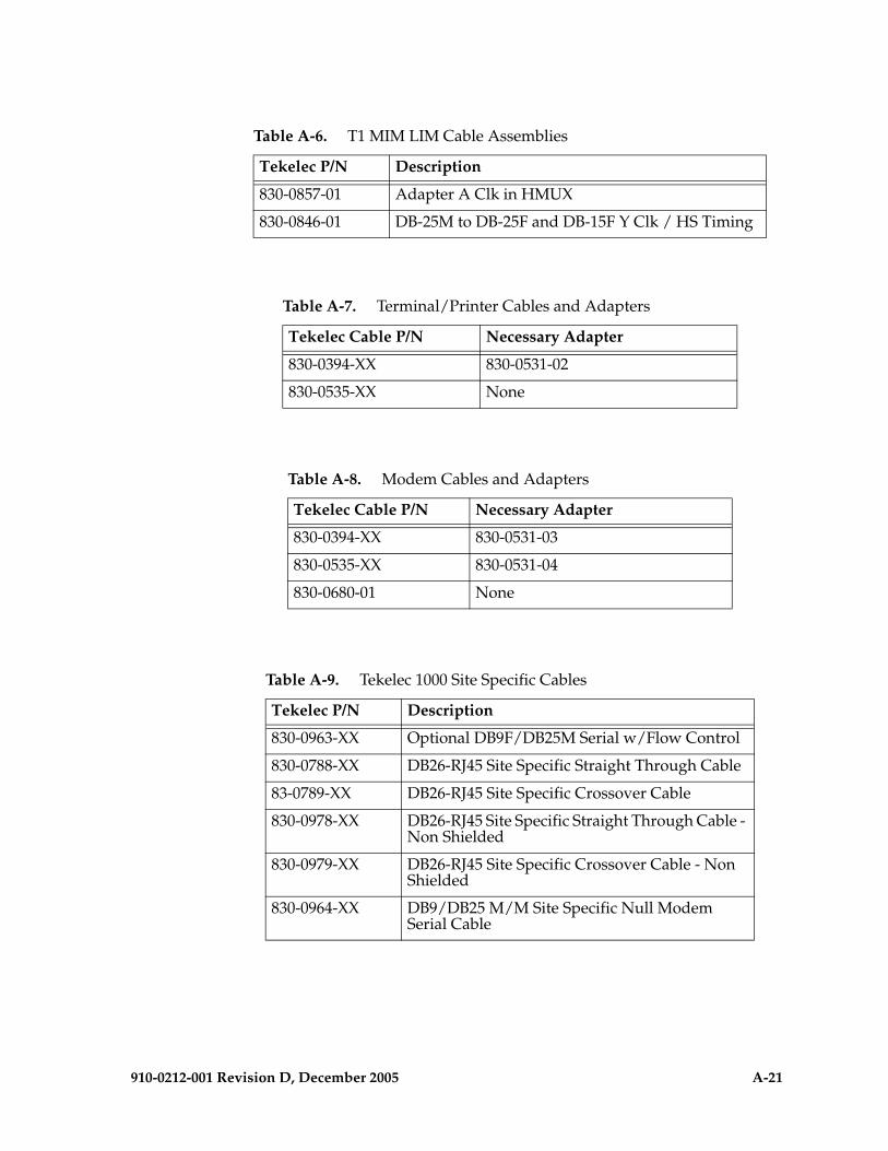
910-0212-001 Revision D, December 2005 A-21
830-0857-01 Adapter A Clk in HMUX
830-0846-01 DB-25M to DB-25F and DB-15F Y Clk / HS Timing
Table A-7. Terminal/Printer Cables and Adapters
Tekelec Cable P/N Necessary Adapter
830-0394-XX 830-0531-02
830-0535-XX None
Table A-8. Modem Cables and Adapters
Tekelec Cable P/N Necessary Adapter
830-0394-XX 830-0531-03
830-0535-XX 830-0531-04
830-0680-01 None
Table A-9. Tekelec 1000 Site Specific Cables
Tekelec P/N Description
830-0963-XX Optional DB9F/DB25M Serial w/Flow Control
830-0788-XX DB26-RJ45 Site Specific Straight Through Cable
83-0789-XX DB26-RJ45 Site Specific Crossover Cable
830-0978-XX DB26-RJ45 Site Specific Straight Through Cable - Non Shielded
830-0979-XX DB26-RJ45 Site Specific Crossover Cable - Non Shielded
830-0964-XX DB9/DB25 M/M Site Specific Null Modem Serial Cable
Table A-6. T1 MIM LIM Cable Assemblies
Tekelec P/N Description
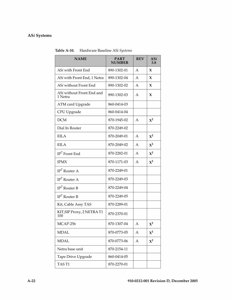
A-22 910-0212-001 Revision D, December 2005
ASi Systems
Table A-10. Hardware Baseline ASi Systems
NAME PART NUMBER
REV ASi 3.8
ASi with Front End 890-1302-01 A X
ASi with Front End, 1 Netra 890-1302-04 A X
ASi without Front End 890-1302-02 A X
ASi without Front End and 1 Netra 890-1302-03 A X
ATM card Upgrade 860-0414-03
CPU Upgrade 860-0414-04
DCM 870-1945-02 A X1
Dial In Router 870-2249-02
EILA 870-2049-01 A X1
EILA 870-2049-02 A X1
IP7 Front End 870-2282-01 A X1
IPMX 870-1171-03 A X1
IP7 Router A 870-2249-01
IP7 Router A 870-2249-03
IP7 Router B 870-2249-04
IP7 Router B 870-2249-05
Kit, Cable Assy TAS 870-2289-01
KIT,SIP Proxy, 2 NETRA T1 100 870-2370-01
MCAP-256 870-1307-04 A X1
MDAL 870-0773-05 A X1
MDAL 870-0773-06 A X1
Netra base unit 870-2154-11
Tape Drive Upgrade 860-0414-05
TAS T1 870-2270-01

910-0212-001 Revision D, December 2005 A-23
NOTE: These components are part of the optional IP7 Front End when it is configured with OEM-based products.
TAS E1 870-2270-02
TAS T1 Card Upgrade 860-0413-01 A
TAS E1 Card Upgrade 860-0413-02 A
TDM 870-0774-08 A X1
VXi MGC, heavy-duty frame, circuit breakers and hubs
890-1375-01 A
VXi with Front End 890-1287-01 A X1
VXi with Netra, heavy-duty frame, CB and Hubs 890-1375-01
Work station 973-1005-01 A X
Table A-10. Hardware Baseline ASi Systems (Continued)
NAME PART NUMBER
REV ASi 3.8

A-24 910-0212-001 Revision D, December 2005
IP7 Front End and IP7 Secure Gateway Releases 1.0 through 6.0
NOTE: IP7 Secure Gateway product baselines beginning with release 7.0 are merged with the Eagle STP.
Table A-11. Hardware Baseline IP7 Front End (FE) and IP7 Secure Gateway (SG) (Sheet 1 of 4)
NAME PART NUMBER
REV IP7 FE 1.0
IP7 SG 1.0, 2.0, 2.2
IP7 SG3.0
IP7 SG4.0
IP7 SG5.0
IP7 SG6.0
ACM 870-1008-02 D X X X X X
ACM 870-1008-03 A X X X X X
ACM 870-1008-04 A X X X X X
ACM 870-1008-05 A X X X X X
ASM 870-1011-02 D X X X X X
ASM 870-1011-03 A X X X X X
ASM 870-1011-04 B X X X X X
ASM 870-1011-05 B X X X X X
ASM 870-1011-06 A X X X X X
ASM 870-1011-07 A X X X X X
CTRL SHELF 870-0775-01 A1 X X X X X
CTRL SHELF 870-0775-02 C3 X X X X X
CTRL SHELF 870-0775-03 E X X X X X
CTRL SHELF 870-0775-04 A3 X X X X X
CTRL SHELF 870-0775-05 A X1 X1 X1 X1 X1
CTRL SHELF 870-0775-06 A X X2 X2 X2 X2 X2
DCM 870-1945-01 A X X X X X
DCM 870-1945-02 A X X X X X X
DCM 870-1945-03 A X X
DCM 870-1945-03 A X X
EDCMDouble-slot 870-2197-01 A X X X
EDCMSingle-slot 870-2372-01 A X X

910-0212-001 Revision D, December 2005 A-25
EDCM-ASingle-slot 870-2508-01 A X X
EILA 870-2049-01 A X X X X X X
EILA 870-2049-02 A X X X X X X
EXTN SHELF 870-0776-02 C5 X X X X X
EXTN SHELF 870-0776-03 D X X X X X
EXTN SHELF 870-0776-06 A X1 X1 X1 X1 X
EXTN SHELF 870-0776-07 A X2 X2 X2 X2 X
EXTN SHELF 870-0776-08 A X X X X X
FAN ASSY 890-1038-01 D X X X X X
FAP 870-1606-xx A X X X X X
FAP- CF/EF 870-0243-08 C X X X X X X
FAP- MISC 870-0243-09 C X X X X X
IP7 Front End w/ FAP
870-2168-02 A X
IP7 Front End w/o FAP
870-2168-01 A X
IPMX 850-0188-01 B X X X X X
IPMX 870-1171-03 A X X
KIT, E1 890-1037-01 A X X X X X
KIT, HLDOVR CLK ASSY
890-1013-01 A X X X X X
LIM-AINF 870-1014-01 D X X X X X
LIM-AINF 870-1014-02 A X X X X X
LIM-AINF 870-1014-03 B X X X X X
LIM-AINF 870-1014-04 A X X X X X
Table A-11. Hardware Baseline IP7 Front End (FE) and IP7 Secure Gateway (SG) (Sheet 2 of 4)
NAME PART NUMBER
REV IP7 FE 1.0
IP7 SG 1.0, 2.0, 2.2
IP7 SG3.0
IP7 SG4.0
IP7 SG5.0
IP7 SG6.0

A-26 910-0212-001 Revision D, December 2005
LIM-AINF 870-1014-05 A X X X X X
LIM-AINF 870-1014-06 A X X X X X
LIM-AINF 870-1488-01 A X X X X X
LIM-AINF 870-1488-02 A X X X X X
LIM-AINF 870-1488-03 A X X X X X
LIM-AINF 870-1488-04 A X X X X X
LIM-AINF 870-1488-05 A X X X X X
LIM-AINF 870-1488-06 A X X X X X
LIM-ATM 870-1293-02 A X X X X X
LIM-ATM 870-1293-03 A X X X X X
LIM-DS0 870-1009-02 D X X X X X
LIM-DS0 870-1009-03 A X X X X X
LIM-DS0 870-1009-04 A X X X X X
LIM-DS0 870-1485-01 A X X X X X
LIM-DS0 870-1485-02 A X X X X X
LIM-DS0 870-1485-03 A X X X X X
LIM-E1 870-1379-01 A X X X X X
LIM-ILA 870-1484-01 E X X X X X
LIM-ILA 870-1484-02 C X X X X X
LIM-OCU 870-1010-03 D X X X X X
LIM-OCU 870-1010-04 A X X X X X
LIM-OCU 870-1010-05 A X X X X X
LIM-OCU 870-1486-02 A X X X X X
LIM-OCU 870-1486-03 A X X X X X
LIM-OCU 870-1486-04 A X X X X X
LIM-V.35 870-1012-02 D X X X X X
LIM-V.35 870-1012-03 A X X X X X
Table A-11. Hardware Baseline IP7 Front End (FE) and IP7 Secure Gateway (SG) (Sheet 3 of 4)
NAME PART NUMBER
REV IP7 FE 1.0
IP7 SG 1.0, 2.0, 2.2
IP7 SG3.0
IP7 SG4.0
IP7 SG5.0
IP7 SG6.0
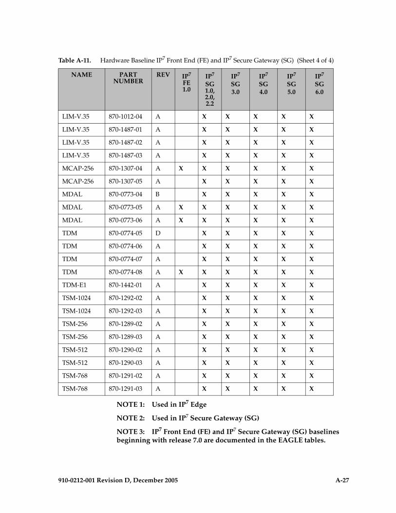
910-0212-001 Revision D, December 2005 A-27
NOTE 1: Used in IP7 Edge
NOTE 2: Used in IP7 Secure Gateway (SG)
NOTE 3: IP7 Front End (FE) and IP7 Secure Gateway (SG) baselines beginning with release 7.0 are documented in the EAGLE tables.
LIM-V.35 870-1012-04 A X X X X X
LIM-V.35 870-1487-01 A X X X X X
LIM-V.35 870-1487-02 A X X X X X
LIM-V.35 870-1487-03 A X X X X X
MCAP-256 870-1307-04 A X X X X X X
MCAP-256 870-1307-05 A X X X X X
MDAL 870-0773-04 B X X X X X
MDAL 870-0773-05 A X X X X X X
MDAL 870-0773-06 A X X X X X X
TDM 870-0774-05 D X X X X X
TDM 870-0774-06 A X X X X X
TDM 870-0774-07 A X X X X X
TDM 870-0774-08 A X X X X X X
TDM-E1 870-1442-01 A X X X X X
TSM-1024 870-1292-02 A X X X X X
TSM-1024 870-1292-03 A X X X X X
TSM-256 870-1289-02 A X X X X X
TSM-256 870-1289-03 A X X X X X
TSM-512 870-1290-02 A X X X X X
TSM-512 870-1290-03 A X X X X X
TSM-768 870-1291-02 A X X X X X
TSM-768 870-1291-03 A X X X X X
Table A-11. Hardware Baseline IP7 Front End (FE) and IP7 Secure Gateway (SG) (Sheet 4 of 4)
NAME PART NUMBER
REV IP7 FE 1.0
IP7 SG 1.0, 2.0, 2.2
IP7 SG3.0
IP7 SG4.0
IP7 SG5.0
IP7 SG6.0

A-28 910-0212-001 Revision D, December 2005
Integrated Sentinel ESP Releases 8.0, 8.1, 8.1.x, 9.0, 10.0, 11.x
In addition to the following Integrated Sentinel ESP Frame release information, the baseline for an Integrated Sentinel ESP release also requires a specific minimum baseline EAGLE release.
Table A-12. ESP Frame Baseline and Required EAGLE Baseline.
ESP Frame Baseline Minimum Required EAGLE Baseline
ESP 8.0 EAGLE 28.0
ESP 8.1 EAGLE 28.2
ESP 9.0 EAGLE 28.2
ESP ATM and EAGLE Time Stamping
EAGLE 28.1
ESP 10.0 and higher EAGLE 28.2
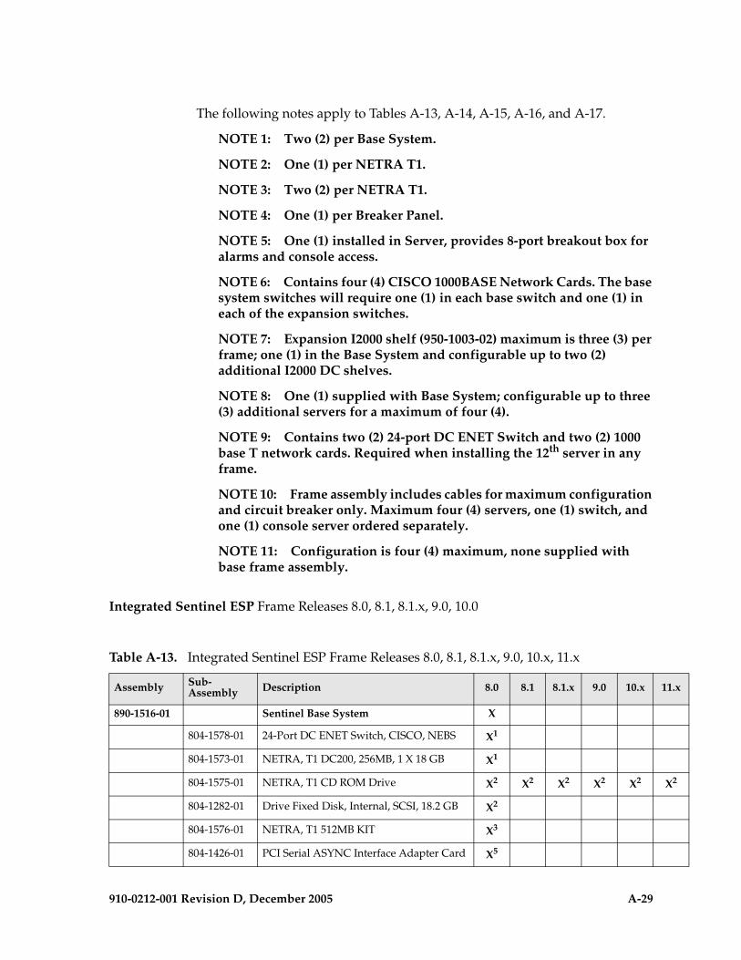
910-0212-001 Revision D, December 2005 A-29
The following notes apply to Tables A-13, A-14, A-15, A-16, and A-17.
NOTE 1: Two (2) per Base System.
NOTE 2: One (1) per NETRA T1.
NOTE 3: Two (2) per NETRA T1.
NOTE 4: One (1) per Breaker Panel.
NOTE 5: One (1) installed in Server, provides 8-port breakout box for alarms and console access.
NOTE 6: Contains four (4) CISCO 1000BASE Network Cards. The base system switches will require one (1) in each base switch and one (1) in each of the expansion switches.
NOTE 7: Expansion I2000 shelf (950-1003-02) maximum is three (3) per frame; one (1) in the Base System and configurable up to two (2) additional I2000 DC shelves.
NOTE 8: One (1) supplied with Base System; configurable up to three (3) additional servers for a maximum of four (4).
NOTE 9: Contains two (2) 24-port DC ENET Switch and two (2) 1000 base T network cards. Required when installing the 12th server in any frame.
NOTE 10: Frame assembly includes cables for maximum configuration and circuit breaker only. Maximum four (4) servers, one (1) switch, and one (1) console server ordered separately.
NOTE 11: Configuration is four (4) maximum, none supplied with base frame assembly.
Integrated Sentinel ESP Frame Releases 8.0, 8.1, 8.1.x, 9.0, 10.0
Table A-13. Integrated Sentinel ESP Frame Releases 8.0, 8.1, 8.1.x, 9.0, 10.x, 11.x
Assembly Sub-Assembly Description 8.0 8.1 8.1.x 9.0 10.x 11.x
890-1516-01 Sentinel Base System X
804-1578-01 24-Port DC ENET Switch, CISCO, NEBS X1
804-1573-01 NETRA, T1 DC200, 256MB, 1 X 18 GB X1
804-1575-01 NETRA, T1 CD ROM Drive X2 X2 X2 X2 X2 X2
804-1282-01 Drive Fixed Disk, Internal, SCSI, 18.2 GB X2
804-1576-01 NETRA, T1 512MB KIT X3
804-1426-01 PCI Serial ASYNC Interface Adapter Card X5
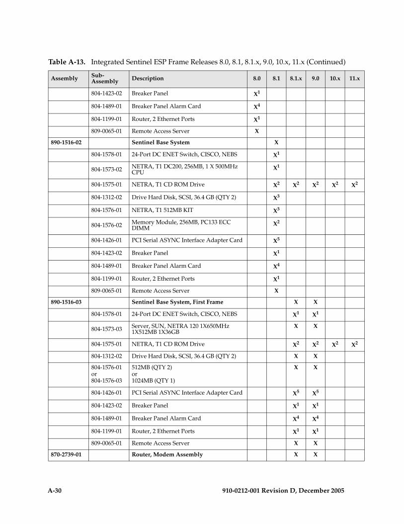
A-30 910-0212-001 Revision D, December 2005
804-1423-02 Breaker Panel X1
804-1489-01 Breaker Panel Alarm Card X4
804-1199-01 Router, 2 Ethernet Ports X1
809-0065-01 Remote Access Server X
890-1516-02 Sentinel Base System X
804-1578-01 24-Port DC ENET Switch, CISCO, NEBS X1
804-1573-02 NETRA, T1 DC200, 256MB, 1 X 500MHz CPU
X1
804-1575-01 NETRA, T1 CD ROM Drive X2 X2 X2 X2 X2
804-1312-02 Drive Hard Disk, SCSI, 36.4 GB (QTY 2) X3
804-1576-01 NETRA, T1 512MB KIT X3
804-1576-02 Memory Module, 256MB, PC133 ECC DIMM
X2
804-1426-01 PCI Serial ASYNC Interface Adapter Card X5
804-1423-02 Breaker Panel X1
804-1489-01 Breaker Panel Alarm Card X4
804-1199-01 Router, 2 Ethernet Ports X1
809-0065-01 Remote Access Server X
890-1516-03 Sentinel Base System, First Frame X X
804-1578-01 24-Port DC ENET Switch, CISCO, NEBS X1 X1
804-1573-03 Server, SUN, NETRA 120 1X650MHz 1X512MB 1X36GB
X X
804-1575-01 NETRA, T1 CD ROM Drive X2 X2 X2 X2
804-1312-02 Drive Hard Disk, SCSI, 36.4 GB (QTY 2) X X
804-1576-01or804-1576-03
512MB (QTY 2)or1024MB (QTY 1)
X X
804-1426-01 PCI Serial ASYNC Interface Adapter Card X5 X5
804-1423-02 Breaker Panel X1 X1
804-1489-01 Breaker Panel Alarm Card X4 X4
804-1199-01 Router, 2 Ethernet Ports X1 X1
809-0065-01 Remote Access Server X X
870-2739-01 Router, Modem Assembly X X
Table A-13. Integrated Sentinel ESP Frame Releases 8.0, 8.1, 8.1.x, 9.0, 10.x, 11.x (Continued)
Assembly Sub-Assembly Description 8.0 8.1 8.1.x 9.0 10.x 11.x
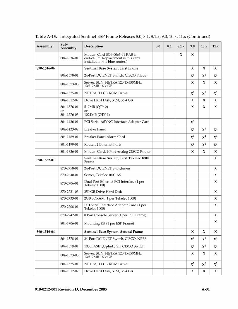
910-0212-001 Revision D, December 2005 A-31
804-1836-01Modem Card (809-0065-01 RAS is end-of-life. Replacement is this card installed in the blue router.)
X X
890-1516-06 Sentinel Base System, First Frame X X X
804-1578-01 24-Port DC ENET Switch, CISCO, NEBS X1 X1 X1
804-1573-03 Server, SUN, NETRA 120 1X650MHz 1X512MB 1X36GB
X X X
804-1575-01 NETRA, T1 CD ROM Drive X2 X2 X2
804-1312-02 Drive Hard Disk, SCSI, 36.4 GB X X X
804-1576-01or804-1576-03
512MB (QTY 2)or1024MB (QTY 1)
X X X
804-1426-01 PCI Serial ASYNC Interface Adapter Card X5
804-1423-02 Breaker Panel X1 X1 X1
804-1489-01 Breaker Panel Alarm Card X4 X4 X4
804-1199-01 Router, 2 Ethernet Ports X1 X1 X1
804-1836-01 Modem Card, 1-Port Analog CISCO Router X X X
890-1832-01 Sentinel Base System, First Tekelec 1000 Frame
X
870-2758-01 24-Port DC ENET Switchmen X
870-2640-01 Server, Tekelec 1000 AS X
870-2706-01 Dual Port Ethernet PCI Interface (1 per Tekelec 1000)
X
870-2721-03 250 GB Drive Hard Disk X
870-2733-01 2GB SDRAM (1 per Tekelec 1000) X
870-2708-01 PCI Serial Interface Adapter Card (1 per Tekelec 1000)
X
870-2742-01 8 Port Console Server (1 per ESP Frame) X
804-1706-01 Mounting Kit (1 per ESP Frame) X
890-1516-04 Sentinel Base System, Second Frame X X X
804-1578-01 24-Port DC ENET Switch, CISCO, NEBS X1 X1 X1
804-1579-01 1000BASET,Uplink, GB, CISCO Switch X1 X1 X1
804-1573-03 Server, SUN, NETRA 120 1X650MHz 1X512MB 1X36GB
X X X
804-1575-01 NETRA, T1 CD ROM Drive X2 X2 X2
804-1312-02 Drive Hard Disk, SCSI, 36.4 GB X X X
Table A-13. Integrated Sentinel ESP Frame Releases 8.0, 8.1, 8.1.x, 9.0, 10.x, 11.x (Continued)
Assembly Sub-Assembly Description 8.0 8.1 8.1.x 9.0 10.x 11.x

A-32 910-0212-001 Revision D, December 2005
804-1576-01or804-1576-03
512MB (QTY 2)or1024MB (QTY 1)
X X X
804-1426-01 PCI Serial ASYNC Interface Adapter Card X5
890-1516-05 Sentinel Base System, Third Frame X X X
804-1578-01 24-Port DC ENET Switch, CISCO, NEBS X1 X1 X1
804-1579-01 1000BASET,Uplink, GB, CISCO Switch X1 X1 X1
804-1573-03 Server, SUN, NETRA 120 1X650MHz 1X512MB 1X36GB
X X X
804-1575-01 NETRA, T1 CD ROM Drive X2 X2 X2
804-1312-02 Drive Hard Disk, SCSI, 36.4 GB X X X
804-1576-01or804-1576-03
512MB (QTY 2)or1024MB (QTY 1)
X X X
804-1426-01 PCI Serial ASYNC Interface Adapter Card X5
804-1423-02 Breaker Panel X1 X1 X1
804-1489-01 Breaker Panel Alarm Card X4 X4 X4
860-0456-01 Assembly Kit, Switch, Expansion X X
804-1578-01 24-Port DC ENET Switch, CISCO, NEBS X1 X1
804-1579-01 1000BASET,Uplink, GB, CISCO Switch X6 X6
870-2439-01 Assembly Kit, NETRA, T1 DC200, Expansion
X
804-1573-01 NETRA, T1 DC200, 256MB, 1 X 18 GB X
804-1575-01 NETRA, T1 CD ROM Drive X2
804-1282-01 Drive Fixed Disk, Internal, SCSI, 18.2 GB X2
804-1576-01 NETRA, T1 512MB KIT (QTY 2) X
870-2439-03 Assembly Kit, NETRA, T1 DC200, Expansion
X
804-1573-02 NETRA, T1 DC200, 256MB, 1 X 500MHz CPU (QTY 2)
X
804-1575-01 NETRA, T1 CD ROM Drive X
804-1312-02 Drive Hard Disk, USCSI, 36.4 GB (QTY 2) X
804-1576-01 NETRA, T1 512MB KIT (QTY 2) X
804-1576-02 Memory Module, 256MB, PC133 ECC DIMM
X
Table A-13. Integrated Sentinel ESP Frame Releases 8.0, 8.1, 8.1.x, 9.0, 10.x, 11.x (Continued)
Assembly Sub-Assembly Description 8.0 8.1 8.1.x 9.0 10.x 11.x

910-0212-001 Revision D, December 2005 A-33
Integrated Sentinel ESP Expansion Frame Releases 8.1.x, 9.0, 10.0
Sentinel Server Frame and Site Collector Frame Release 8.1.x, 9.0, 10.0
Table A-14. Integrated Sentinel ESP Expansion Frame Releases 8.1.x, 9.0, 10.0
Assembly Sub-Assembly Description 8.1.x 9.0 10.0
870-0117-01 Kit, ESP Interframe Expansion, Sentinel X X X
804-1578-01 24-Port DC ENET Switch, CISCO, NEBS X9 X9 X9
804-1579-01 1000BASET,Uplink, GB, CISCO Switch X6 X6 X6
870-0118-01 Kit, 2nd and 3rd ESP Interframe Expansion, Sentinel X X X
804-1579-01 1000BASET,Uplink, GB, CISCO Switch X6 X6
870-2655-01 Server (NETRA 120), Expansion X X X
804-1573-03 Server, SUN, NETRA 120 1X650MHz 1X512MB 1X36GB X X X
804-1312-02 Drive Hard Disk, USCSI, 36.4 GB X X X
804-1575-01 NETRA, T1 CD ROM Drive X X X
804-1576-01or804-1576-03
512MB (QTY 2)or1024MB (QTY 1)
X X X
Table A-15. Sentinel Server Frame Releases 8.1.x, 9.0, 10.0, 11.x
Assembly Sub-Assembly Description 8.1.x 9.0 10.0 11.x
890-1774-01 Final Server Frame Assembly X X
804-1695-01 Base System, NETRA 20, DC Power X8 X8
804-1312-02 Drive Hard Disk, SCSI, 36.4 GB (QTY 2) X X
804-1696-01 CPU 900 MHz (One per server, Alarm Server requires 2) X X
804-1697-01 2GB (4 x 512MB DIMM) X X
804-1601-02 Disk Drive, 73GB (QTY 2 per server) X X
804-1585-01 Single Ethernet Card (QTY 1 per server) X X
804-1426-01 PCI Serial ASYNC Interface Adapter Card X5 X5
804-1423-06 Circuit breaker X1 X1
804-1489-01 Breaker Panel Alarm Card X1 X1
890-1774-02 Assembly, Final Server X10 X10 X10
804-1423-06 Circuit breaker X1 X1 X1

A-34 910-0212-001 Revision D, December 2005
804-1489-01 Breaker Panel Alarm Card X1 X1 X1
870-2656-01 Netra 20 Expansion Server X X
804-1695-01 Base System, NETRA 20, DC Power X8 X8
804-1696-01 CPU 900 MHz (One per server, Alarm Server requires 2) X X
804-1697-01 2GB (4 x 512MB DIMM) X X
804-1601-02 Disk Drive, 73GB (QTY 2 per server) X X
804-1585-01 Single Ethernet Card (QTY 1 per server) X X
870-2656-02 Netra 20 Server X
804-1695-05 Server, SUN, NETRA 20 2X1200MHz 4X512MB 2X73GB X11 X11 X11
804-1545-01 Drive 14X Max/10X Min DVD-ROM (Netra Server) X X X
804-1585-01 Single Ethernet Card (QTY 1 per server) X X X
870-2640-01 Tekelec 1000 Traffic Database Server X
804-1696-01 CPU 900 MHz (One per server, Alarm Server requires 2) X X
870-2441-01 24-Port ENET GarrettCom Switch (One required per frame, not supplied with base frame assembly)
X X X
804-1580-01 ENET Switch, 24-Port X X X
870-2742-01 Console Server, 8-Port (One required per frame assembly)
X X X
804-1808-03 Console Server, MRVLX 8 port with Modem DC power X X X
Table A-15. Sentinel Server Frame Releases 8.1.x, 9.0, 10.0, 11.x
Assembly Sub-Assembly Description 8.1.x 9.0 10.0 11.x
Table A-16. Site Collector Frame Releases 8.1.x and 9.0.
Assembly Sub-Assembly Description 8.1.x 9.0
890-1772-01 Assembly, Final Flight Recorder Frame X X
804-1312-02 Drive Hard Disk, USCSI, 36.4 GB X X
804-1573-03 Server, SUN, NETRA 120 1X650MHz 1X512MB 1X36GB X X
804-1575-01 NETRA, T1 CD ROM Drive X X
804-1576-01 NETRA, T1 512MB KIT (QTY 2) X X
804-1426-01 PCI Serial ASYNC Interface Adapter Card X5 X5
804-1198-01 10/100 Switching DC Hub with Bridge X X
955-1003-02 I200 Snap Shelf DC power with power supply X X
950-2150-01 Power Supply, 48V DC Snap
804-1423-05 Circuit breaker X1 X1

910-0212-001 Revision D, December 2005 A-35
AXi System Release 1.0
804-1489-01 Breaker Panel Alarm Card X1 X1
870-2655-01 Expansion, Flight Recorder X X
804-1573-03 Server, SUN, NETRA 120 1X650MHz 1X512MB 1X36GB X X
804-1312-02 Drive Hard Disk, USCSI, 36.4 GB X X
804-1575-01 NETRA, T1 CD ROM Drive X X
804-1576-01 NETRA, T1 512MB KIT (QTY 2) X X
955-1003-02 I2000 Snap Shelf DC power wish power supply X7 X7
950-2150-01 Power Supply, 48V DC Snap X7 X7
Table A-16. Site Collector Frame Releases 8.1.x and 9.0.
Table A-17. AC Servers Releases 8.1.x and 9.0
Assembly Sub-Assembly Description 8.1.x 9.0
870-2692-01 Server, SUN, V120 1X650MHz 2X36GB Disks 1536MB MEM CDROM AC Power Cord
X X
804-1172-02 Power cord, SUN North America to IEC 6.6FT X X
804-1312-02 Drive Hard Disk, USCSI, 36.4 GB X X
804-1575-01 NETRA, T1 CD ROM Drive X X
804-1576-01 NETRA, T1 512MB KIT (QTY 2) X X
804-1772-02 Server, SUN V120 1X650MHz 1X512MB 1X36GB X X
Table A-18. AXi System Release 1.0 (Sheet 1 of 6)
Assembly Sub-Assembly
Compo-nent Description
REV
Comments
890-1663-01 Final Assy VPN, AXi 500 A
870-2248-03 CIRCUIT BREAKER PANEL ASSY A 2 per frame
804-1423-03 CIRCUIT BREAKER PANEL,7/7, 15A, 3A,15A,5A,20A,1A,10A
870-2589-07 NETRA 1400 NETWORK SERVER 1 A
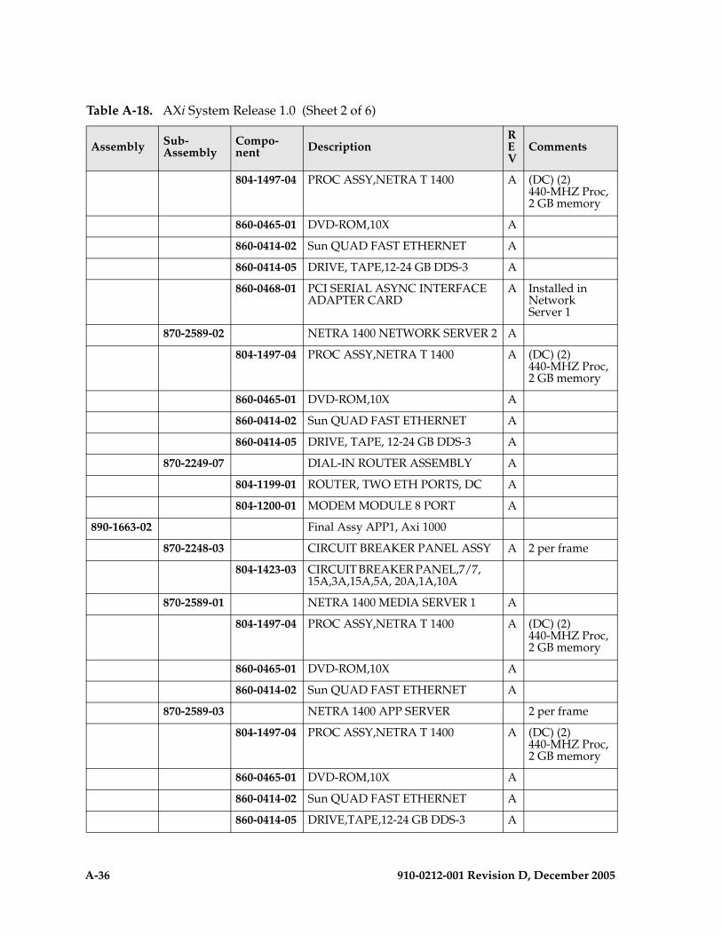
A-36 910-0212-001 Revision D, December 2005
804-1497-04 PROC ASSY,NETRA T 1400 A (DC) (2) 440-MHZ Proc,2 GB memory
860-0465-01 DVD-ROM,10X A
860-0414-02 Sun QUAD FAST ETHERNET A
860-0414-05 DRIVE, TAPE,12-24 GB DDS-3 A
860-0468-01 PCI SERIAL ASYNC INTERFACE ADAPTER CARD
A Installed in Network Server 1
870-2589-02 NETRA 1400 NETWORK SERVER 2 A
804-1497-04 PROC ASSY,NETRA T 1400 A (DC) (2) 440-MHZ Proc,2 GB memory
860-0465-01 DVD-ROM,10X A
860-0414-02 Sun QUAD FAST ETHERNET A
860-0414-05 DRIVE, TAPE, 12-24 GB DDS-3 A
870-2249-07 DIAL-IN ROUTER ASSEMBLY A
804-1199-01 ROUTER, TWO ETH PORTS, DC A
804-1200-01 MODEM MODULE 8 PORT A
890-1663-02 Final Assy APP1, Axi 1000
870-2248-03 CIRCUIT BREAKER PANEL ASSY A 2 per frame
804-1423-03 CIRCUIT BREAKER PANEL,7/7, 15A,3A,15A,5A, 20A,1A,10A
870-2589-01 NETRA 1400 MEDIA SERVER 1 A
804-1497-04 PROC ASSY,NETRA T 1400 A (DC) (2) 440-MHZ Proc,2 GB memory
860-0465-01 DVD-ROM,10X A
860-0414-02 Sun QUAD FAST ETHERNET A
870-2589-03 NETRA 1400 APP SERVER 2 per frame
804-1497-04 PROC ASSY,NETRA T 1400 A (DC) (2) 440-MHZ Proc,2 GB memory
860-0465-01 DVD-ROM,10X A
860-0414-02 Sun QUAD FAST ETHERNET A
860-0414-05 DRIVE,TAPE,12-24 GB DDS-3 A
Table A-18. AXi System Release 1.0 (Sheet 2 of 6)
Assembly Sub-Assembly
Compo-nent Description
REV
Comments

910-0212-001 Revision D, December 2005 A-37
860-0466-01 PCI DUAL DIFF. ULTRA SCSI HOST ADAPTER
A
870-2160-03 RAID ASSY,4 X 36 GB DISKS,DC, NTW
A 2 per frame
804-1310-02 RAID ARRAY, NETRA A1000 A
870-2437-01 ASSY,24 PORT DC ENET SWITCH B1
2 per frame
804-1578-01 24 PORT,DC ENET,SWITCH A
890-1663-04 Final Assy NET, AXi 1000 A
870-2248-03 CIRCUIT BREAKER PANEL ASSY A 2 per frame
804-1423-03 CIRCUIT BREAKER PANEL,7/7, 15A,3A,15A,5A, 20A,1A,10A
870-2589-07 NETRA 1400 NETWORK SERVER 1 A
804-1497-04 PROC ASSY,NETRA T 1400 A (DC) (2) 440-MHZ Proc,2 GB memory
860-0465-01 DVD-ROM,10X A
860-0414-02 Sun QUAD FAST ETHERNET A
860-0414-05 DRIVE, TAPE, 12-24 GB DDS-3 A
860-0468-01 PCI SERIAL ASYNC INTERF ADAPTER CARD
A Installed in Network Server 1
870-2589-02 NETRA 1400 NETWORK SERVER 2 a
804-1497-04 PROC ASSY,NETRA T 1400 A (DC) (2) 440-MHZ Proc,2 GB memory
860-0465-01 DVD-ROM,10X A
860-0414-02 Sun QUAD FAST ETHERNET A
860-0414-05 DRIVE, TAPE,12-24 GB DDS-3 A
870-2589-01 DIAL-IN ROUTER ASSEMBLY A
804-1497-04 PROC ASSY,NETRA T1400 A (DC) (2) 440-MHZ Proc,2 GB memory
860-0465-01 DVD-ROM,10X A
860-0414-02 Sun QUAD FAST ETHERNET A
870-2249-07 DIAL-IN ROUTER ASSEMBLY A
804-1199-01 ROUTER, TWO ETH PORTS, DC A
Table A-18. AXi System Release 1.0 (Sheet 3 of 6)
Assembly Sub-Assembly
Compo-nent Description
REV
Comments
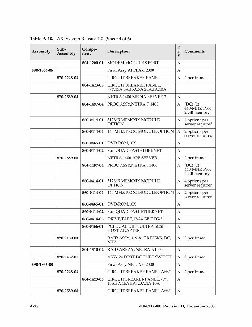
A-38 910-0212-001 Revision D, December 2005
804-1200-01 MODEM MODULE 8 PORT A
890-1663-06 Final Assy APPI,Axi 2000 A
870-2248-03 CIRCUIT BREAKER PANEL A 2 per frame
804-1423-03 CIRCUIT BREAKER PANEL, 7/7,15A,3A,15A,5A,20A,1A,10A
870-2589-04 NETRA 1400 MEDIA SERVER 2 A
804-1497-04 PROC ASSY,NETRA T 1400 A (DC) (2) 440-MHZ Proc,2 GB memory
860-0414-01 512MB MEMORY MODULE OPTION
A 4 options per server required
860-0414-04 440 MHZ PROC MODULE OPTION A 2 options per server required
860-0465-01 DVD-ROM,10X A
860-0414-02 Sun QUAD FASTETHERNET A
870-2589-06 NETRA 1400 APP SERVER A 2 per frame
804-1497-04 PROC ASSY,NETRA T1400 A (DC) (2) 440-MHZ Proc,2 GB memory
860-0414-01 512MB MEMORY MODULE OPTION
A 4 options per server required
860-0414-04 440 MHZ PROC MODULE OPTION A 2 options per server required
860-0465-01 DVD-ROM,10X A
860-0414-02 Sun QUAD FAST ETHERNET A
860-0414-05 DRIVE,TAPE,12-24 GB DDS-3 A
860-0466-01 PCI DUAL DIFF. ULTRA SCSI HOST ADAPTER
A
870-2160-03 RAID ASSY, 4 X 36 GB DISKS, DC, NTW
A 2 per frame
804-1310-02 RAID ARRAY, NETRA A1000 A
870-2437-01 ASSY,24 PORT DC ENET SWITCH A 2 per frame
890-1663-08 Final Assy NET, Axi 2000 A
870-2248-03 CIRCUIT BREAKER PANEL ASSY A 2 per frame
804-1423-03 CIRCUIT BREAKER PANEL, 7/7, 15A,3A,15A,5A, 20A,1A,10A
A
870-2589-08 CIRCUIT BREAKER PANEL ASSY A
Table A-18. AXi System Release 1.0 (Sheet 4 of 6)
Assembly Sub-Assembly
Compo-nent Description
REV
Comments

910-0212-001 Revision D, December 2005 A-39
804-1423-03 CIRCUIT BREAKER PANEL,7/7, 15A,3A,15A,5A, 20A,1A,10A
A
870-2589-08 NETRA 1400 NETWORK SERVER 1 A
804-1497-04 PROC ASSY,NETRA T1400 A (DC) (2) 440-MHZ Proc,2 GB memory
860-0414-01 512MB MEMORY A 4 options per server required
860-0414-04 440 MHZ PROC MODULE OPTION A 2 options per server required
860-0465-01 DVD-ROM, 10X A
860-0414-02 Sun QUAD FAST ETHERNET A
860-0414-05 DRIVE, TAPE,12-24 GB DDS-3 A
860-0468-01 PCI SERIAL ASYNC INTERFADAPTER CARD
A Installed in Network Server 1
870-2589-05 NETRA 1400 NETWORK SERVER 2 A
804-1497-04 PROC ASSY,NETRA T1400 A (DC) (2) 440-MHZ Proc,2 GB memory
860-0414-01 512MB MEMORY A 4 options per server required
860-0414-04 440 MHZ PROC MODULE OPTION A 2 options per server required
860-0465-01 DVD-ROM,10X A
860-0414-02 Sun QUAD FAST ETHERNET A
860-0414-05 DRIVE, TAPE,12-24 GB DDS-3 A
870-2589-04 NETRA 1400 MEDIA SERVER A
804-1497-04 PROC ASSY,NETRA T1400 A (DC) (2) 440-MHZ Proc,2 GB memory
860-0414-01 512MB MEMORY OPTION A 4 options per server required
860-0414-04 440 MHZ PROC MODULE OPTION A 2 options per server required
860-0465-01 DVD-ROM,10X A
860-0414-02 Sun QUAD FAST ETHERNET A
870-2249-07 DIAL-IN ROUTER ASSEMBLY A
Table A-18. AXi System Release 1.0 (Sheet 5 of 6)
Assembly Sub-Assembly
Compo-nent Description
REV
Comments
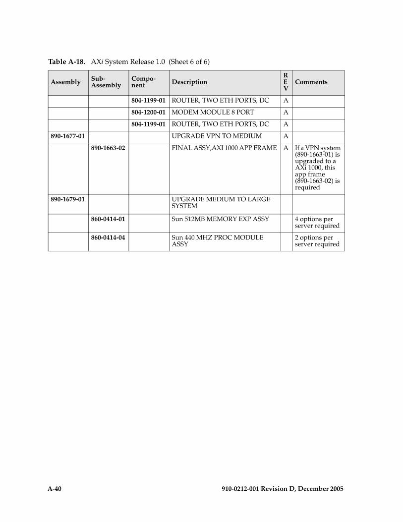
A-40 910-0212-001 Revision D, December 2005
804-1199-01 ROUTER, TWO ETH PORTS, DC A
804-1200-01 MODEM MODULE 8 PORT A
804-1199-01 ROUTER, TWO ETH PORTS, DC A
890-1677-01 UPGRADE VPN TO MEDIUM A
890-1663-02 FINAL ASSY,AXI 1000 APP FRAME A If a VPN system (890-1663-01) is upgraded to a AXi 1000, this app frame (890-1663-02) is required
890-1679-01 UPGRADE MEDIUM TO LARGE SYSTEM
860-0414-01 Sun 512MB MEMORY EXP ASSY 4 options per server required
860-0414-04 Sun 440 MHZ PROC MODULE ASSY
2 options per server required
Table A-18. AXi System Release 1.0 (Sheet 6 of 6)
Assembly Sub-Assembly
Compo-nent Description
REV
Comments

910-0212-001 Revision D, December 2005 B-1
B
Sentinel 4-Port MonitorAppliques
Introduction ..................................................................................................... B–2
4-Port T1 Monitor Applique.......................................................................... B–2
4-Port E1 Monitor Applique.......................................................................... B–4
4-Port DS0 Monitor Applique ....................................................................... B–6
4-Port V.35 Monitor Applique ....................................................................... B–7
4-Port DSCS Monitor Applique .................................................................... B–8
DSCS Bridge Amplifier .................................................................................. B–9

B-2 910-0212-001 Revision D, December 2005
Introduction
This appendix provides reference information on each 4-port monitor applique that Sentinel supports:
• 4-Port T1 Monitor Applique
• 4-Port E1 Monitor Applique
• 4-Port DS0 Monitor Applique
• 4-Port V.35 Monitor Applique
• 4-Port DSCS Monitor Applique
Hardware options on an applique can be set using shelf configuration software, as described in the section Configuring a Sentinel Shelf in Chapter 3, Configuring and Administering Sentinel of the Sentinel 9.0 User’s Manual P/N 910-4377.
This chapter includes instructions for installing the DSCS Bridge Amplifier.
4-Port T1 Monitor Applique
The 4-Port T1 Monitor applique (part number 850-0463-02) increases the monitoring link density offered by a single shelf from 16 links to 64 links per single 23” shelf (P/N 955-2002-01) or per Signaling Node Application Platform (SNAP). The applique allows monitoring of T1 spans in the following configurations:
• Four T1 spans each with a single signaling channel
• A single T1 span with a maximum of four signaling channels
• A single T1 span monitoring two signaling channels and two other T1 spans monitoring one signaling channel each
• A single T1 span monitoring three signaling channels and a single T1 span monitoring one signaling channel
• Two T1 spans monitoring two signaling channels each
NOTE: The monitored T1 span can be located up to a maximum of 500 ft. from the shelf.
Each monitoring port within the 4-Port T1 Monitor applique provides non-intrusive high impedance bidirectional monitoring for T1 (100 Ohm) links. All hardware options on the T1 Monitor applique can be set using shelf configuration software. See Figure B-1 for an example of the 4-Link T1 Monitor Configuration window.

910-0212-001 Revision D, December 2005 B-3
Figure B-1. T1 4-Link Monitor Configuration Window
Use the two slider bars on the T1 4-Link Monitor Configuration Screen to map the physical T1 span and channel selection to the link A,B,C, or D.
Each T1 span has various configuration parameters that you may set with the toggle buttons shown in Figure B-1. They are described briefly in the following paragraphs.
Zero Suppression: AMI or B8ZS. B8ZS is Binary (or Bipolar) Eight Zero Suppression. A data transmission format used to solve certain bandwidth signaling problems. B8ZS coding enables interface equipment to recognize an all zeroes condition in a data byte. The equipment substitutes a B8ZS code for the all-zero byte; the code contains intentional violations of the AMI format. The violation is sent across the network. It contains sufficient ones to allow the system to remain in synchronization. The destination CSU replaces the code with the all-zeroes byte.
AMI is a formatting code for T1/E1 transmissions over twisted-pair copper cable. T1 transmissions are in bipolar form. AMI represents a zero (or space) by the absence of a voltage; a one (or mark) is represented by a positive or negative pulse, depending on whether the preceding one was negative or positive; that is, marks are inverted on an alternating basis.
Framing: Selects the framing option, 193S or 193E. With 193S framing, a superframe is made up of 12 frames. With a 193E framing, a superframe is made up of 24 frames.

B-4 910-0212-001 Revision D, December 2005
Gain Selection: 0db or +20db. When set to 0db, the connection to the monitored T1 span is assumed to be made via a direct connection to the T1 span. When set to +20db, the connection to the monitored T1 span is assumed to be made using a patch panel with 20db of attenuation at the monitor position (for example, 470 Ω resistors in series with tip/ring).
NOTE: Spans originating from another LIC (for example, port B of LIC 1 daisy-chained into port A of LIC 2) are considered a direct connection; therefore, set the Gain Selection to 0db.
4-Port E1 Monitor Applique
The 4-Port E1 Monitor appliques (part number 850-0463-01) increase the monitoring link density offered by a single shelf from 16 links to 64 links per single 23” shelf (P/N 955-2002-01) or per Signaling Node Application Platform (SNAP). The applique allows monitoring E1 spans in the following configurations:
• Four E1 spans each with a single signaling channel
• A single E1 span with a maximum of four signaling channels
• A single E1 span monitoring two signaling channels and two other E1 spans monitoring one signaling channel each
• A single E1 span monitoring three signaling channels and a single E1 span monitoring one signaling channel
• Two E1 spans monitoring two signaling channels each
NOTE: The monitored E1 span can be located up to a maximum of 500 ft. from the shelf.
Each monitoring port within the 4-Port E1 Monitor applique provides non-intrusive high impedance bidirectional monitoring for E1 (75 and 120 Ohm) links. All hardware options on the applique can be set using shelf configuration software. See Figure B-2 for an example of the 4-Link E1 Monitor Configuration window.
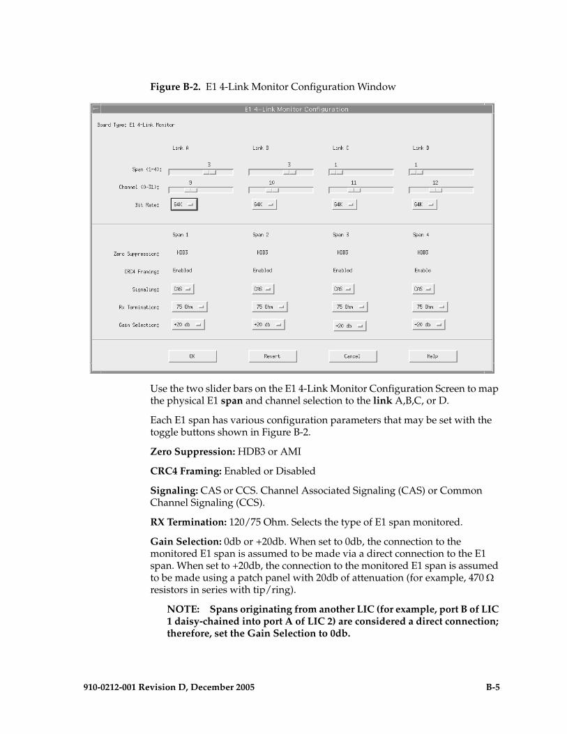
910-0212-001 Revision D, December 2005 B-5
Figure B-2. E1 4-Link Monitor Configuration Window
Use the two slider bars on the E1 4-Link Monitor Configuration Screen to map the physical E1 span and channel selection to the link A,B,C, or D.
Each E1 span has various configuration parameters that may be set with the toggle buttons shown in Figure B-2.
Zero Suppression: HDB3 or AMI
CRC4 Framing: Enabled or Disabled
Signaling: CAS or CCS. Channel Associated Signaling (CAS) or Common Channel Signaling (CCS).
RX Termination: 120/75 Ohm. Selects the type of E1 span monitored.
Gain Selection: 0db or +20db. When set to 0db, the connection to the monitored E1 span is assumed to be made via a direct connection to the E1 span. When set to +20db, the connection to the monitored E1 span is assumed to be made using a patch panel with 20db of attenuation (for example, 470 Ω resistors in series with tip/ring).
NOTE: Spans originating from another LIC (for example, port B of LIC 1 daisy-chained into port A of LIC 2) are considered a direct connection; therefore, set the Gain Selection to 0db.

B-6 910-0212-001 Revision D, December 2005
4-Port DS0 Monitor Applique
The 4-Port DS0 Monitor applique (part number 850-0481-01) increases the monitoring link density offered by a single shelf from 16 links to 64 links per single 23” shelf (P/N 955-2002-01) or per Signaling Node Application Platform (SNAP). The applique allows monitoring DS0 spans in the following configuration:
• Four DS0 spans each providing a single signaling channel
Each monitoring port within the 4-Port DS0 Monitor applique provides non-intrusive high impedance bidirectional monitoring for DS0 links. All hardware options on the applique can be set using shelf configuration software. See Figure B-3 for an example of the 4-Link DS0 Monitor Configuration window.
Figure B-3. DS0 4-Link Monitor Configuration Window
Each DS0 span has various configuration parameters that may be set with the toggle buttons shown in Figure B-3.
Bit Rate: 56K or 64K. This selection determines if the clock used to capture data from the DS0 signaling link is the 56Kbs or 64Kbs clock generated on the clock card.
Gain Selection: 0db or +20db. When set to 0db, the connection to the monitored DS0 span is assumed to be made using a direct connection to the span. When set to +20db, the connection to the monitored span is assumed to be made using a patch panel with 20db of attenuation (e.g. 470 Ω resistors in series with tip/ring).
NOTE: Spans originating from another LIC (for example, port B of LIC 1 daisy-chained into port A of LIC 2) are considered a direct connection; therefore, set the Gain Selection to 0db.
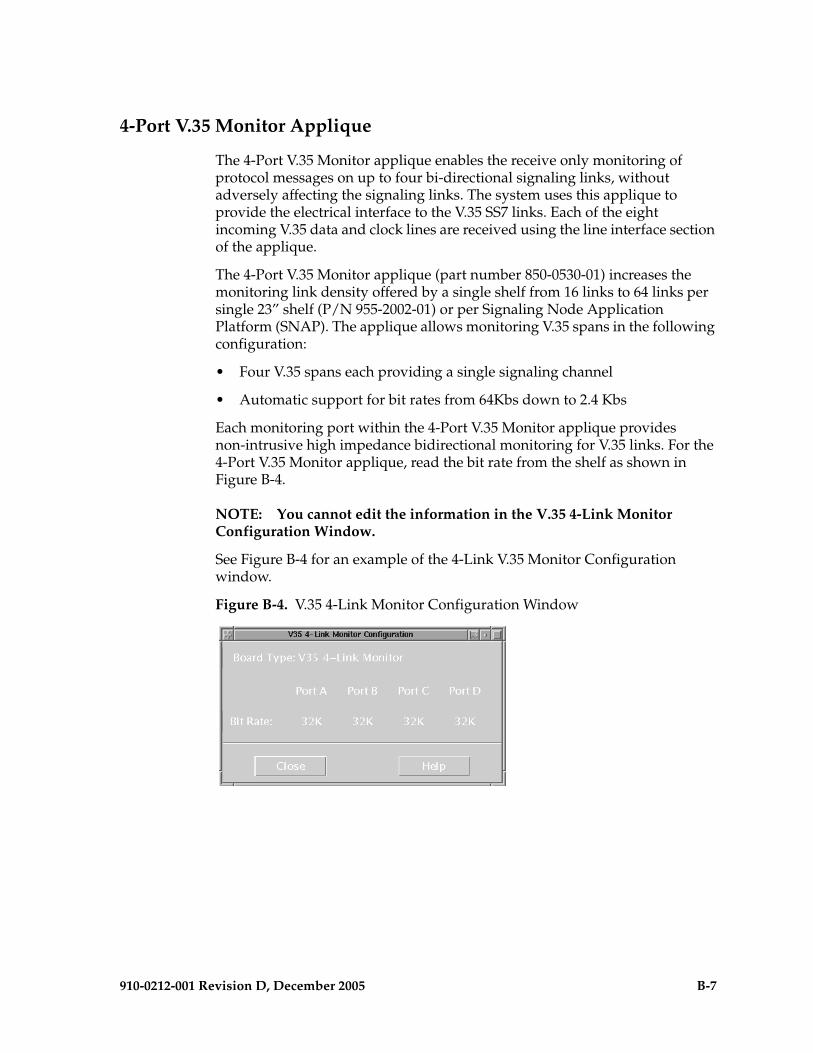
910-0212-001 Revision D, December 2005 B-7
4-Port V.35 Monitor Applique
The 4-Port V.35 Monitor applique enables the receive only monitoring of protocol messages on up to four bi-directional signaling links, without adversely affecting the signaling links. The system uses this applique to provide the electrical interface to the V.35 SS7 links. Each of the eight incoming V.35 data and clock lines are received using the line interface section of the applique.
The 4-Port V.35 Monitor applique (part number 850-0530-01) increases the monitoring link density offered by a single shelf from 16 links to 64 links per single 23” shelf (P/N 955-2002-01) or per Signaling Node Application Platform (SNAP). The applique allows monitoring V.35 spans in the following configuration:
• Four V.35 spans each providing a single signaling channel
• Automatic support for bit rates from 64Kbs down to 2.4 Kbs
Each monitoring port within the 4-Port V.35 Monitor applique provides non-intrusive high impedance bidirectional monitoring for V.35 links. For the 4-Port V.35 Monitor applique, read the bit rate from the shelf as shown in Figure B-4.
NOTE: You cannot edit the information in the V.35 4-Link Monitor Configuration Window.
See Figure B-4 for an example of the 4-Link V.35 Monitor Configuration window.
Figure B-4. V.35 4-Link Monitor Configuration Window

B-8 910-0212-001 Revision D, December 2005
4-Port DSCS Monitor Applique
The 4-Port DSCS Monitor applique provides an electrical and physical interface for up to 4 DSCS links. DB25 connectors on the rear of the MGTS shelf provide the mechanical interface to the DSCS links. The 4-Port DSCS Monitor applique uses the “A” and “B” DB25 connector ports of the ALICE LIC as the interface to four duplex ports per DB25 connector. Each duplex port requires four signals on the DB25 connector.
4-Port DSCS Monitor applique configuration options include the following:
• The 4-Port DSCS Monitor applique supports up to four bidirectional channels operating at a maximum of 56 Kbits/sec with 0 - 100% message signal unit occupancy
• The Sentinel shelf must be within 35 feet of the monitored link unless you are using a DSCS Bridge Amplifier.
See Figure B-5 for an example of the 4-Link DSCS Monitor Configuration window.
Figure B-5. 4-Link DSCS Monitor Configuration Window
The cable connections for the DSCS Monitor applique are the same as for the T1, E1, and DS0 Monitor appliques. Please refer to Appendix A of the Signaling/Cellular Generic Hardware Reference manual for information on the cable connections.
The Digital Signal Customer Service (DSCS) interface supports the non-intrusive monitoring of switching events. This interface requires:
• One 4-port DSCS Monitor Applique for each four links monitored
• One 16-port DSCS Bridge Amplifier (described in the following section) for every four DSCS Monitor Appliques
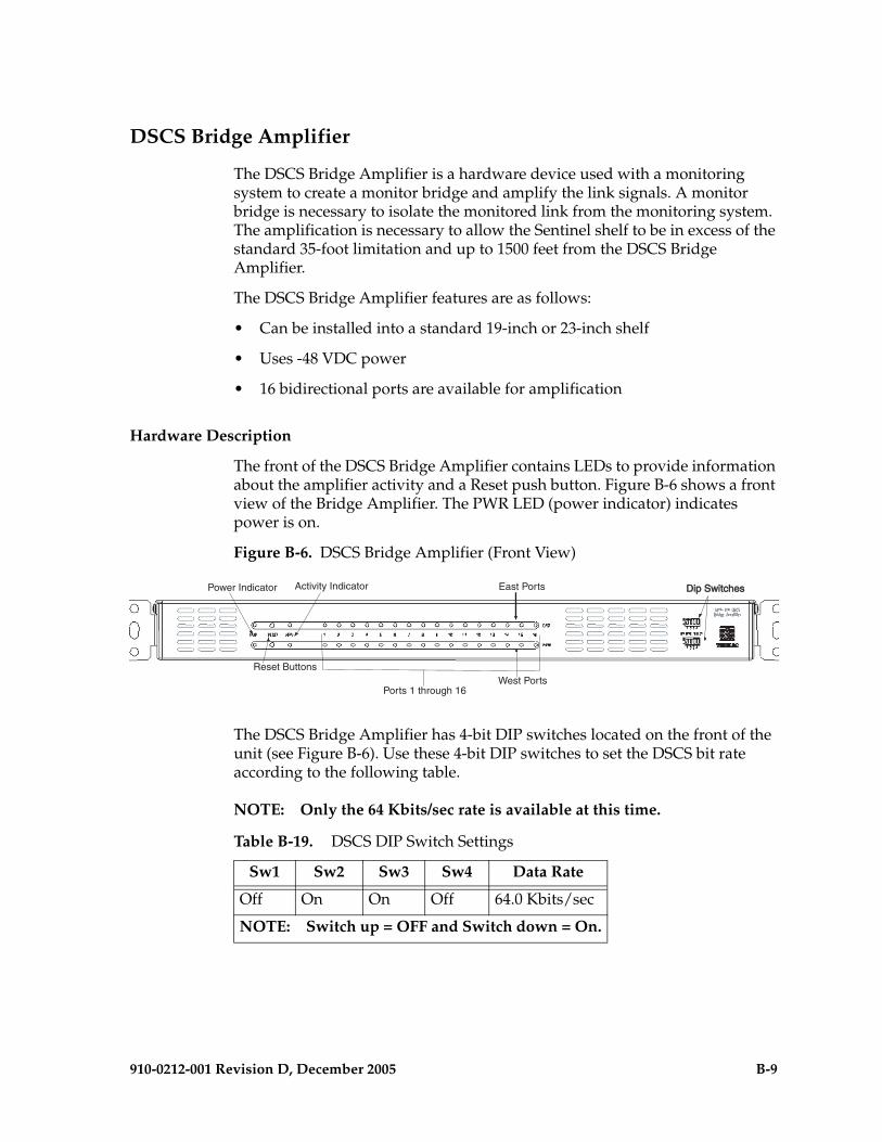
910-0212-001 Revision D, December 2005 B-9
DSCS Bridge Amplifier
The DSCS Bridge Amplifier is a hardware device used with a monitoring system to create a monitor bridge and amplify the link signals. A monitor bridge is necessary to isolate the monitored link from the monitoring system. The amplification is necessary to allow the Sentinel shelf to be in excess of the standard 35-foot limitation and up to 1500 feet from the DSCS Bridge Amplifier.
The DSCS Bridge Amplifier features are as follows:
• Can be installed into a standard 19-inch or 23-inch shelf
• Uses -48 VDC power
• 16 bidirectional ports are available for amplification
Hardware Description
The front of the DSCS Bridge Amplifier contains LEDs to provide information about the amplifier activity and a Reset push button. Figure B-6 shows a front view of the Bridge Amplifier. The PWR LED (power indicator) indicates power is on.
Figure B-6. DSCS Bridge Amplifier (Front View)
The DSCS Bridge Amplifier has 4-bit DIP switches located on the front of the unit (see Figure B-6). Use these 4-bit DIP switches to set the DSCS bit rate according to the following table.
NOTE: Only the 64 Kbits/sec rate is available at this time.
Power Indicator
Reset Buttons
Activity Indicator
Ports 1 through 16
East Ports
West Ports
Dip SwitchesDip Switches
Table B-19. DSCS DIP Switch Settings
Sw1 Sw2 Sw3 Sw4 Data Rate
Off On On Off 64.0 Kbits/sec
NOTE: Switch up = OFF and Switch down = On.

B-10 910-0212-001 Revision D, December 2005
The rear of the DSCS Bridge Amplifier supports the power inputs and port accessibility shown in Figure B-7. A DC 2 terminal barrier strip, chassis ground screw, and a fuse are located on the right side of the back of the amplifier.
Figure B-7. DSCS Bridge Amplifier (Rear View)
The link inputs are on the left and they are labeled “To Links.” The monitor outputs to the monitoring equipment are on the right rear and they are labeled “To MON.” Each link incorporates a Transmit and Receive Tip and Ring pair. Because the terms transmit and receive depend on the perspective, and each pair is monitored the same way, the terms East and West are used to signify the direction.
East pairs are wire-wrapped to Tip (labeled “T”) and Ring (labeled “R”) pins on top of the rear of the amplifier. West pairs are wire-wrapped to the Tip and Ring pins on the bottom. See Figure B-7 for a rear view of the amplifier.
Figure B-7 also shows the mounting brackets used to mount the Bridge Amplifier in the 23-inch rack.
Installation
The DSCS Bridge Amplifier can be mounted in a standard 19-inch or 23-inch shelf. Mounting holes are located on each side of the amplifier. Use the following procedure to make all the connections and configure the amplifier for first use.
Procedure — Install DSCS Bridge Amplifier
1 Make sure the mounting brackets are properly attached to fit your rack configuration. The DSCS Bridge Amplifier accommodates either a 19- or 23-inch shelf
Mounting brackets
Inputs from links Output to monitoringPower inputs
Ground
equipment (monitor)(monitored links)

910-0212-001 Revision D, December 2005 B-11
2 Use the mounting holes located on either side of the DSCS Bridge Amplifier to rack mount the amplifier.
3 Connect monitored links of the device(s) under test (DUT) to the appropriate wire-wrap pins on the rear panel of the amplifier. The inputs are on the left rear and are labeled “To Links.”
4 Connect the monitoring equipment inputs to the appropriate wire-wrap pins on the rear panel of the amplifier. The monitor outputs to the monitoring equipment are on the right rear and are labeled “To MON.”
5 Connect a safety ground wire to the ground (GND) screw on the rear panel.
6 Connect the DC power cable to the power inputs.
Part Number
Use the following part numbers to order:
Limitations
The following limitations apply to the DSCS Bridge Amplifier installation:
• The cable lengths connecting the Bridge Amplifier and the monitored and monitoring equipment must adhere to the following conditions. Also, see Figure B-8.
— x3 must be less than or equal to 9 feet . . . AND
— x1 + x4 must be less than 2000 feet . . . AND
— x2 + x4 must be less than 2000 feet
Table B-20. DSCS Bridge Amplifier Part Numbers
Part Number Description
977-2019-04 DSCS Bridge Amplifier
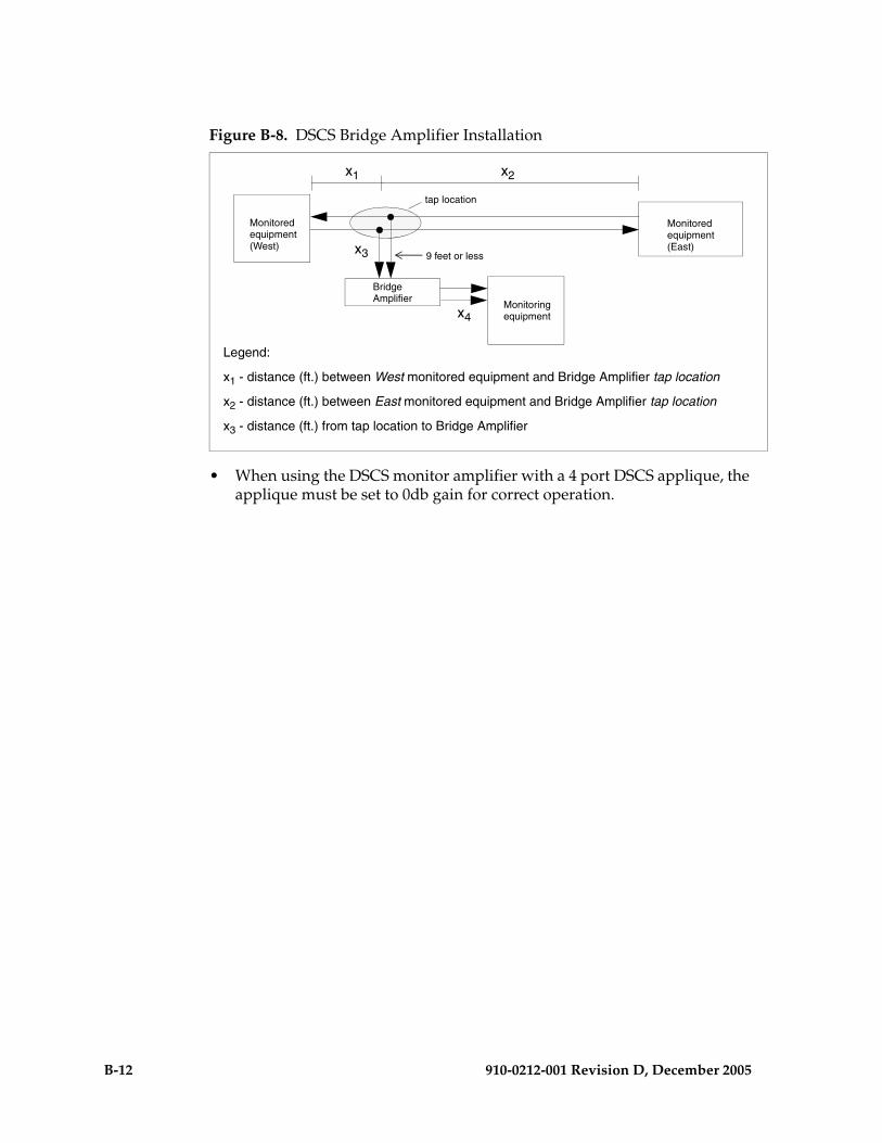
B-12 910-0212-001 Revision D, December 2005
Figure B-8. DSCS Bridge Amplifier Installation
• When using the DSCS monitor amplifier with a 4 port DSCS applique, the applique must be set to 0db gain for correct operation.
Monitoredequipment
Monitoredequipment
BridgeAmplifier
9 feet or less(West) (East)
Monitoringequipment
x1 x2
x3
x4
tap location
Legend:
x1 - distance (ft.) between West monitored equipment and Bridge Amplifier tap location
x2 - distance (ft.) between East monitored equipment and Bridge Amplifier tap location
x3 - distance (ft.) from tap location to Bridge Amplifier
910-0212-001 Revision D, December 2005 Index-1
Index
4-port DS0 monitor applique B-64-port DSCS monitor applique B-84-port E1 monitor applique B-44-port T1 monitor applique B-24-port V.35 monitor applique B-7840-0064-01 3-6840-0089-01 3-6870-2238-01 3-6870-2278-01 3-6870-2508-01 1-7890-0001-01 3-1208-Port Connector Box
description 4-31, 4-38, 4-43
AACM 3-21, 3-37, 3-96alarm card, MPS Server
description 4-28alarm connectors 3-26alarms
MPS Server LEDs 4-32Alarms Reference and User’s Manual 1-18Application Communication Module 2-12Application Communication Module (ACM)
3-19application communication module (ACM)
3-94Application Communications Modules
(ACMs) 3-20Application Interface (AINF) 3-68Application Processor (AP) 3-62Application Service Module 2-14Application Service Module (ASM) 3-88application service module (ASM) 3-18Application Subsystem 2-8Application-Specific Integrated Circuits
4-26appliques
4-port DS0 monitor B-64-port DSCS monitor B-84-port E1 monitor B-44-port T1 monitor B-24-port V.35 monitor B-7
architecture, MPS Server I/O 4-28
ASi 4000 SCP 2-24, 4-3ASi 4000 Service Control Point 1-8AXi 1000 4-19AXi 2000 4-19AXi Application Frame 1 4-14AXi Network Frame 4-14AXi Systems 1-10
BBITS connectors 3-27box, 8-Port Connector
see 8-Port Connector BoxBreaker panels 4-52Bridge Amplifier B-9Building Integrated Timing System (BITS)
3-27, 3-64, 3-68building requirements 6-3
Ccard
MPS Server alarm 4-28Quad FastEthernet Network Interface
4-31SAI/P 4-31, 4-43
CD-ROM 3-151, 3-153specification 4-27
Clear To Send (CTS) 3-67Clock
HCMIM 3-117Clock A 3-32Common Language Location Identifier 1-23Communication Module (ACM) 3-9Communication Subsystem 2-6Communications Processor (CP) 3-63communications processor (CP) 3-98Components of OEM-Based Products 2-30components, MPS
storage 4-27Connector Box, 8-Port
see 8-Port Connector BoxControl Frame (CF) 3-4control frame (CF) 3-18control shelf backplane 3-21CPU

Index-2 910-0212-001 Revision D, December 2005
MPS Server specifications 4-27Critical Alarm 3-5Customer Assistance 1-20Customer Service Report 1-23Customer Service Request 1-21Cyclic Redundancy Check (CRC) 3-98
DData Collection Applications Manual 1-18Data Communication Equipment (DCE)
3-67Data Communications Module 3-19Data Terminal Equipment (DTE) 3-27, 3-67Data Terminal Ready (DTR) 3-67Database Communications Module 2-12Database Communications Module (DCM)
3-9Database Service Module (Eagle STP) 2-14DCM 3-18, 3-19, 3-20, 3-21, 3-28, 3-37, 6-10Dimensions and Weight 4-23DIP switch settings B-9Direct Memory Access (DMA) 3-68, 3-98disks, MPS Server SCSI 4-27Documentation Packaging, Delivery, and
Updates 1-20documents
Alarms Reference and User’s Manual 1-18
Data Collection Applications Manual 1-18
Feature Notice 1-17hardware and installation 1-18list of Sentinel 1-17Release Notice 1-18System Administrator’s Guide 1-18technical reference documents 1-19User’s Manual 1-18
Double 3-19DRAM 3-92drive, tape
see tape driveDS0 4-link monitor configuration window
B-6DS0 monitor applique B-6DS0A 3-68DSCS bridge amplifier
description B-9
DIP switch settings B-9front view B-9installing B-10limitations B-11part number B-11rear view B-10
DSM 3-21, 3-37DVD-ROM
specification 4-27dynamic random access memory (DRAM)
3-92
EE1 3-19, 3-21, 3-105, 3-111E1 4-link Monitor Configuration window
B-5E1 backplane 3-107, 3-112E1 monitor applique B-4EAGLE 5 SAS 1-6Eagle STP 1-6Eagle STP and IP7 Secure Gateway Systems
2-3EAGLE-Based Products 1-6earthquake resistance 6-4EBI 3-53EDCM 3-19, 3-81EDCM-A 1-7, 3-85Eight-Port Connector Box 4-55EILA 3-18, 3-19, 3-21, 3-37ELAP
MPS Server memory to support 4-27Embedded Operations Applications
Processor 2-18emergency response 1-23end panels 3-6environmental requirements 6-4EOAP 1-7EPAP
MPS Server memory to support 4-27ESP 4-39ESP Servers 5-15ESP Subsystem Hardware Components 5-15Ethernet
Quad FastEthernet Network Interface card 4-31
ethernet applique 3-96EXT ALM 3-26

910-0212-001 Revision D, December 2005 Index-3
Extended Services Platform Host Servers 4-39
Extension Frame (EF) 3-4, 3-9extension frame (EF) 3-9extension shelf 3-28extension shelf backplane 3-31External Alarm (EXT ALM) 3-26external alarm connector 3-26External/Customer Alarm Interface 3-52
FFan Tray 3-120Feature Guide
documentsFeature Guide 1-17
Feature Notice 1-17features
MPS system additional 4-28floor loading 6-5frame, MPS
layout 4-13front view
hub 4-47MPS frame layout 4-13MPS Server 4-25MPS Server detail 4-22, 4-30Netra t 1400 4-25
Fuse Alarm Interface 3-52Fuse and Alarm Panel 3-123, 3-133Fuse and Alarm Panel (FAP) 3-7, 3-14, 3-22,
3-31fuse and alarm panel (FAP) 3-121fuse and alarm panel P/N 804-0007-06
3-129, 3-132, 3-138Fuse and Alarm Panel Rear View 3-130
GGateway Screening (GWS) 3-88General Purpose Relay Connectors 3-28General Purpose Serial Interface Connector
3-28GP01 3-28GP02 3-28GPSI 3-28GR-376 EOAP 2-19grounding 6-5
HHard Disk Drive 3-54Hardware and Installation Manuals 1-18hardware descriptions -i, 3-1, 4-1Hardware Notes 6-13Hardware Repair and Return 1-24hardware return 1-24hardware, MPS
overview 4-12hardware, MPS frame
layout 4-13HCMIM 3-113, 3-114
dependencies 3-114description 3-113requirements 3-114timing 3-117
High Density Interconnect (HDI) 3-21, 3-31High speed IMT packet router 3-38High-Capacity Multichannel Interface
Module 3-113High-Speed Master Timing 2-18High-Speed Multiplexer 2-8HIPR 3-38HMUX 3-37, 3-43holdover clock 3-141hub
description 4-47, 4-50front LEDs 4-48, 4-50front view 4-47rear view 4-48
II/O architecture, MPS Server 4-28I/O connectors 3-27, 3-32ILA 3-18, 3-19, 3-21, 3-37, 3-56, 3-57IMT 3-7, 3-19, 3-28, 3-32, 3-91IMT connectors 3-28, 3-32IMT interface circuits 3-63indicator lights
tape drive 4-21Installation Manuals 1-18Integrated LIM Appliques (ILAs) 3-18Integrated Sentinel 2-20, 5-8Integrated Sentinel (ESP Frame Side) 2-23Integrated Sentinel EAGLE STP Side 1-6Integrated Sentinel Hardware Overview 5-9
Index-4 910-0212-001 Revision D, December 2005
Integrated Serial Communications Controller (ISCC) 3-64, 3-65, 3-67, 3-68
Interface 3-104interface
MPS Server SCSI 4-28Quad FastEthernet Network Interface
card 4-31SAI/P card 4-31, 4-43
Inter-processor Message Transport 2-6Interprocessor Message Transport 3-98Interprocessor Message Transport (IMT)
3-7, 3-9, 3-61interprocessor message transport (IMT)
interface 3-88, 3-94, 3-101Introduction 1-1, 2-2IP 3-19IP7 Front End 4-4, 4-5, 4-6, 4-9, 4-44IP7 Secure Gateway 1-6
LLabel Kit 3-137LAN 4-47, 4-50layout
MPS frame 4-13LCA (Logic Cell Array) 3-65LEDs
hub front 4-48, 4-50MPS Server 4-28, 4-32MPS Server alarm 4-32Netra t 1400 4-37
lighting 6-3LIM 3-21LIM-AINF 3-56LIM-ATM- 3-58, 3-69LIM-V.35 3-56Link 3-20Link Interface Module 2-11link interface module (LIM) 3-19Link Interface Modules (LIMs) 3-9Local Maintenance Center (LMC) 3-26local maintenance center (LMC) alarm
connector 3-26Logic Cell Array (LCA) 3-68
MMaintenance and Administration Subsystem
2-4Maintenance and Administration Subsystem
(MAS) 3-18maintenance disk and alarm card (MDAL)
3-46Maintenance Interface System (MIS) 3-143Major Alarm 3-5manual
organization 3-44manuals
Alarms Reference and User’s Manual 1-18
Data Collection Applications Manual 1-18
Feature Guide 1-17Feature Notice 1-17hardware and installation manuals 1-18list of Sentinel 1-17Release Notice 1-18System Administrator’s Guide 1-18technical reference documents 1-19User’s Manual 1-18
MAS 3-18MASP 2-5, 3-19Matrix Controller Automatic 3-146MAU 3-97Maximum weight 6-5MCA 3-146MDAL 3-19, 3-21, 3-37Measurements Platform IP Security 2-13Media Access Unit 3-97Media Access Unit (MAU) 3-96memory
MPS Server for ELAP support 4-27MPS Server for EPAP support 4-27
Memory Applique 3-92Minor Alarm 3-5MIS 3-141Miscellaneous Frame 3-129Miscellaneous Frame (MF) 3-4miscellaneous frame (MF) 3-14mounting bracket
8-Port Connector Box 4-12MPL 3-21, 3-37MPS frame
front view 4-13
910-0212-001 Revision D, December 2005 Index-5
rear view 4-13MPS hardware
frame layout 4-13overview 4-12
MPS Host Servers 4-25MPS Server
see also MPS systemalarm card
description 4-28CD-ROM 4-27CPU specifications 4-27DVD-ROM 4-27front detail view 4-22, 4-30front view 4-25I/O architecture 4-28LEDs 4-28, 4-32memory to support EPAP and ELAP 4-27Netra t 1400 4-25networking ports 4-28operating system 4-28overview 4-25parallel ports 4-28Quad FastEthernet Network Interface
card 4-31rear detail view 4-22, 4-30rear view 4-26SCSI disks 4-27SCSI interface 4-28serial ports 4-28serial ports SAI/P card 4-31, 4-43storage components 4-27tape drive 4-27, 4-29
MPS systemadditional features 4-28Ethernet hub description 4-47, 4-50
MPS/EPAP 4.0 1-8, 4-11Multi 3-19Multi-Platform Server (MPS) Systems 2-24Multi-Purpose Server 1-8, 4-11
NNetra t 1400
see also MPS Serverfront view 4-25LEDs 4-32rear view 4-26
network
MPS Server ports 4-28Quad FastEthernet Network Interface
card 4-31Non-Integrated Sentinel Solutions 2-29NSD Systems 1-5
OOAP 3-26OAP Alarm (OAPALM) 3-26OAPALM 3-26OAPF 3-148, 4-46OCU 3-68OEM-Based Network Elements 2-30OEM-Based Peripheral Components 2-31OEM-Based Products 1-8OEM-Based Products and Elements 2-24OEM-Based Servers 2-30Office Channel Unit (OCU) 3-65operating system, Solaris 7 4-28Operations Support System Application
Processor frame (OAPF) 3-4Operations Support System Application
Processors (OAP) 3-3Operations Support System Applications
Processor 1-9, 2-25operations system support applications
processor frame (OAPF) 3-16Overview 1-3, 3-43Overview Sentinel Products 5-3
PP/N 830-0425-01 3-97P/N 850-0330-03 3-21, 3-22, 3-26, 3-27, 3-43P/N 850-0356-03 Extension Shelf Back Plane
3-14P/N 870-1008-xx 3-94P/N 870-1606-01 3-121, 3-132P/N 890-1037-01 3-105parallel ports, MPS Server 4-28PCI cards
Quad FastEthernet Network Interface card 4-31
SAI/P 4-31, 4-43PCI slots 4-35PLXO 3-145ports

Index-6 910-0212-001 Revision D, December 2005
8-Port Connector Box, serial 4-31, 4-38, 4-43
MPS Server networking 4-28MPS Server parallel 4-28MPS Server serial 4-28SAI/P card 4-31, 4-43
Power Converter Unit 3-54, 3-63, 3-99Power Distribution 3-31power requirements 6-8Problem-Major 1-21Problem-Minor 1-22Probless Solution 5-8probless Solution 5-8processor, MPS Server CPU 4-27publications, Sentinel 1-17
QQuad FastEthernet card 4-35Quad FastEthernet Network Interface card
description 4-31
RRack Alarm (RALMx) 3-26rack and row alarm connector 3-26Radio Frequency Interference (RFI) 3-31rear view
hub 4-48MPS frame layout 4-13MPS Server 4-26MPS Server detail 4-22, 4-30
Related Publications 1-12Release Notice 1-18remote maintenance center (RMC) alarm
connector 3-26Repair and Return Shipping Instructions
1-27Request To Send (RTS) 3-67Response 1-23return shipment 1-28Returning a Crate 1-28routers 4-48Row Alarm (ROW ALM) 3-26ROW ALM 3-26RS-485 3-107
SSAI/P card
description 4-31, 4-43SAP
technical reference documents 1-19Scope and Audience 1-4, 3-44SCSI
disks, MPS Server 4-27MPS Server interface 4-28
Sentinel Frames 5-4Sentinel Products 5-1Sentinel publications 1-17Sentinel Site Collector Frame with Flight
Recorders 1-9Sentinel Transport Cards 2-22serial port connectors 3-27serial ports
8-Port Connector Box 4-31, 4-38, 4-43MPS Server 4-28SAI/P card 4-31, 4-43
Server, MPSsee MPS Server
Shelf Clock Connectors 3-28Signaling Transfer Point, Local Area
Network (SLAN) 6-10Signaling/Cellular Generic Hardware
Reference 1-18Site Collector Frames 5-6site engineering 6-1Small Computer System Interface Buses 2-6Solaris 7 operating system 4-28space requirements 6-3spare card storage shelf 3-14specifications
MPS Server CPU 4-27tape drive 4-27
SRAM 3-92Status Indicators (SI) 3-144storage components, MPS Server 4-27Stratum-3 (ST3) 3-141, 3-145System Administrator’s Guide 1-18System Clock 2-15system clock connectors 3-26, 3-32system unit
front view 4-37

910-0212-001 Revision D, December 2005 Index-7
TT1 4-link monitor configuration window B-3T1 monitor applique B-2T-1000 5-3Tape 4-35tape drive
description 4-29specification 4-27
TDM 3-18, 3-21, 3-37TDM technical specifications 3-54Technical Reference Documents 1-19Technical Services 1-21Tekelec 1000 4-11Tekelec 1000 Applications Server 5-3Tekelec 1000 APS 1-8Tekelec Signaling Products Hardware
Manual 1-18Tekelec Signaling Products Integrated
Applications Installation Manual 1-18
Tekelec Technical Services 1-23Terminal Processor 3-52Test and Maintenance Features 3-99Time Slot Counter Synchronization 2-18Timing 3-117Timing Systems Eagle STP/IP7 SG 2-15TOCA 3-141, 3-145TOCA Card 3-146Transaction Services Module (TSM) 3-100Translation 3-20Translation Service Module (TSM) 3-19Translation Service Modules (TSMs) 3-9,
3-18, 3-28Translation Services Module 2-14TSM 3-21, 3-37TXCO 3-145
UUser’s Manual 1-18
VV.35 3-68V.35 4-link monitor configuration window
B-7V.35 applique 3-66, 3-67V.35 monitor applique B-7VCXO 3-145
viewhub front 4-47hub rear 4-48MPS frame front 4-13MPS frame rear 4-13MPS Server front 4-25MPS Server front detail 4-22, 4-30MPS Server rear 4-26MPS Server rear detail 4-22, 4-30Netra t 1400 front 4-25Netra t 1400 rear 4-26
VPN Systems 4-17
Wweights 6-5

Index-8 910-0212-001 Revision D, December 2005