hardware manual...power/relay packs, wall switches, panels and dimmers. this creates a system with...
TRANSCRIPT

HA
RD
WA
RE
MA
NU
AL

For Technical Support Call1.800.PASSIVE [3209] v2.4

CONTENTS
1 nLight® Control System Overview 04 1.1 Introduction 04 1.2 System Architecture 05 1.2.1 nLight Enabled Device 05 1.2.2 nLight Control Zone 06 1.2.3 nLight Channel 07 1.2.4 nLight Operational Mode 10 1.2.5 nLight Backbone Network 14 1.3 System Power 16 1.4 System Control 17 2 Hardware Installation 18 2.1 Install Backbone 19 2.2 Install Zones w/ Power Packs 20 2.3 Install Zones w/o Power Packs 21 2.4 Complete nLight Installation Worksheet 21 2.5 Manual Unit Identification 22 3 Manual Programming [Local] 22 3.1 Sensors, Power Packs, & nIOs 22 3.2 Gateway LCD Screen & Touch Controls 34 3.3 Wireless Bridge 36 3.4 WallPod™ 39 4 Remote Programming via SensorView™ 40 5 Hardware Troubleshooting Aids 41

1 nLIGHT® CONTROL SYSTEM OVERVIEW
1.1 INTRODUCTION What is nLight?
nLight is a technology that integrates time-based, occupancy-based, daylight-based, and manual lighting control.
How does nLight work?nLight works by establishing a digital communication network between intelligent lighting control devices, including: occupancy sensors, photocells, power/relay packs, wall switches, panels and dimmers. This creates a system with distributed intelligence, as well as enables global access to the building’s lighting system via web-based management software called SensorView.
What is Distributed Intelligence?Distributed intelligence means that all lighting control actions, such as turning on/off or dimming lights, are carried out locally within each individual lighting zone. This feature reduces the wiring requirements and associated labor costs. Additionally, distributed intelligence enables each zone of nLight devices to self-commission and function independently, while still benefiting from being part of a larger networked system.
How are nLight devices similar to other Sensor Switch sensors?All occupancy and daylighting features from Sensor Switch’s standard (non-nLight) product lines have been integrated into corresponding nLight devices. This includes Passive Infrared and Microphonics occupancy detection technologies, 0-10 VDC dimming control, stepped dimming control, automatic photocell set-point programming, 100 hr burn-in control, etc.
TIME-BASEDDAYLIGHTING
MANUALOCCUPANCY
=

5
1.2 SYSTEM ARCHITECTURE
The nLight architecture is based on the five underlying concepts defined in this section: • nLight Enabled Device • nLight Control Zone • nLight Channels • nLight Operational Modes • nLight Backbone
1.2.1 nLIGHT ENABLED DEVICE
nLight Enabled devices are the most basic elements in the nLight architecture and have model numbers beginning with the letter “n” (e.g., nCM 9).
Types of nLight Enabled devices include occupancy sensors, photocell sensors, power/relay packs, relay/dimming panels, WallPods, and luminaires.
All nLight Enabled devices are equipped with RJ-45 communication ports.
All devices consist of one or more basic lighting control components. • Occupancy sensor • Photocell • Manual Switch • Dimmer • Relay • Interface Devices (for luminaires)
See reference section for detailed feature descriptions of all nLight enabled devices.
DEFINITIONA device having the ability to communicate over an nLight network.

1.2.2 nLIGHT® CONTROL ZONE
An example of a typical nLight zone is an office lobby with an nLight Enabled occupancy sensor, power/relay pack, and WallPod controlling the lighting.
Zones…
…may consist of a single device, several different device types, or multiple devices of the same type.
…use CAT5e cables to interconnect devices (daisy chained in any order).
…may have 1,500 ft of total cable length.,
…can function stand-alone if disconnected from Gateway/SensorView.
DEFINITIONA collection of nLight Enabled devices that function together in order to control a distinct space’s lighting

7
1.2.3 nLIGHT® CHANNELS
Every nLight zone has 16 channels of occupancy, 16 channels of photocell, and 16 switch channels on which to communicate information (see diagram).
Any device with a sensor, photocell, and/or switch can broadcast each type of information on one respective channel.
For Example:• An occupancy sensor (e.g., nCM 9) can broadcast its occupancy
information on an occupancy channel (1-16).• A combined occupancy sensor and photocell (e.g., nCM 9 P) can
broadcast its occupancy information on an occupancy channel (1-16) and its photocell information on a photocell channel (1-16).
• WallPods can broadcast manual switches on a switch channel (1-16).
Any device with a relay and/or dimming output can listen (track) on one or more of each information type’s channels simultaneously. By default all broadcasting and tracking settings are set to channel 1. Two pole units default to channels 1 & 2, scene controller buttons default to 1-4.
DEFINITIONDistinct communication lanes within an nLight control zone that are used to transfer information between nLight enabled devices
Basic Control Zone

Example Zone Using Multiple Channels• Classroom with 4 circuits of lights (3 main light rows, 1 white board light)• Two occupancy sensors both broadcasting on occupancy channel OC-1• Four WallPods broadcasting on switch channels SW-1, SW-2, SW-3, and
SW-4 respectively• One photocell broadcasting on photocell channel PC-1• Four power packs tracking on occupancy channel OC-1, each tracking
a different switch channel (SW-1, SW-2, SW-3, SW-4), and two tracking photocell channel PC-1
Physical Device ConnectionsPHYSICAL CONNECTIONS
Occ Sensor 2
Power Pack 4 Power Pack 3 Power Pack 2 Power Pack 1
To Bridge
WallPod 1 WallPod 2 WallPod 3 WallPod 4
Occ Sensor 1 Photocell

9
Logical Channel Connections
LOGICAL CONNECTIONS
Occ Sensor 1 OC-1
Power Pack 1
Power Pack 2
Power Pack 3
Power Pack 4
WallPod 1
SW-1
WallPod 2
WallPod 3
WallPod 4
Occ Sensor 2
Photocell
PC-1
OC-1
OC-1
SW-2
SW-3
OC-1
SW-4
PC-1
Occ Channels
1
2
45 6
7
89
1110
12
14
16
15
13
3
Photocell Channels
1
2
45 6
7
89
1110
12
14
16
15
13
3
Switch Channels
1
2
4
5
6
7
8
9
11
10
12
14
16
15
133
CHANNEL 1
CHANNEL 1
CHANNEL 1
CHANNEL 2
CHANNEL 3
CHANNEL 4

Operational Modes are defined by device settings (see list and definitions below) that can be programmed via SensorView or device push-button. The default operational mode of a device is stored within each device, however temporary modes can be enabled on demand from SensorView or via a time-based profile.
NORMAL The name of the state where a device’s relay and/or dimming output is not overridden and therefore will react according to the other operational mode settings. When all devices are running their factory defaults, the following operation results:
Automatic On Zones with occupancy sensors automatically turn lights on when occupant
is detected
Automatic Off Zones with occupancy and/or photocell sensors turn lights off when
vacancy or sufficient daylight is detected
Permanent Off Pressing the a switch will turn lights off. The lights will remain off regardless
of occupancy until switch is pressed again, restoring the sensor to Automatic On functionality
OVERRIDE ONForces a device’s relay closed and/or dimming output to maximum
OVERRIDE OFFForces a device’s relay open and/or dimming output to minimum
1.2.4 nLIGHT OPERATIONAL MODES
DEFINITIONThe behavior of relays and/or dimming outputs when events such as occupancy, daylight, or manual switching occur
11
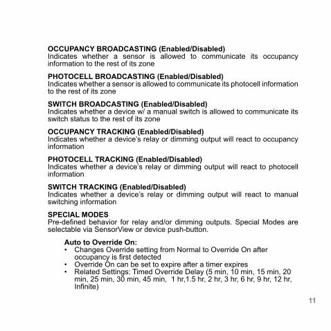
OCCUPANCY BROADCASTING (Enabled/Disabled) Indicates whether a sensor is allowed to communicate its occupancy information to the rest of its zone
PHOTOCELL BROADCASTING (Enabled/Disabled)Indicates whether a sensor is allowed to communicate its photocell information to the rest of its zone
SWITCH BROADCASTING (Enabled/Disabled)Indicates whether a device w/ a manual switch is allowed to communicate its switch status to the rest of its zone
OCCUPANCY TRACKING (Enabled/Disabled) Indicates whether a device’s relay or dimming output will react to occupancy information
PHOTOCELL TRACKING (Enabled/Disabled) Indicates whether a device’s relay or dimming output will react to photocell information
SWITCH TRACKING (Enabled/Disabled)Indicates whether a device’s relay or dimming output will react to manual switching information
SPECIAL MODESPre-defined behavior for relay and/or dimming outputs. Special Modes are selectable via SensorView or device push-button.
Auto to Override On: • Changes Override setting from Normal to Override On after
occupancy is first detected• Override On can be set to expire after a timer expires • Related Settings: Timed Override Delay (5 min, 10 min, 15 min, 20
min, 25 min, 30 min, 45 min, 1 hr,1.5 hr, 2 hr, 3 hr, 6 hr, 9 hr, 12 hr, Infinite)

SPECIAL MODES CONT
Manual to Override On: • Changes Override setting from Override Off to Override On• Override On can be set to expire after a timer expires • Related Setting: Timed Override Delay (5 min, 10 min, 15 min, 20 min,
25 min, 30 min, 45 min, 1 hr,1.5 hr, 2 hr, 3 hr, 6 hr, 9 hr, 12 hr, Infinite)
Manual On to Fully Automatic: • Changes Override setting from Override Off to Normal after switch is
first used
Semi-Automatic (Manual On):• Changes Override setting from Override Off to Normal after each time
switch is first used and from Normal to Override Off after sensor times out
Predictive Off:• After switch is pressed, lights turn off and a short “exit timer” begins.
After timer expires, sensor scans the room to detect whether occupant is still present. If no occupancy is detected, zone returns to auto-on

13

An nLight network backbone consists of special nLight Enabled devices called “Bridges” and “Gateways” that work together to transport and route information between control zones and the SensorView software.
Within a typical nLight network, multiple zones are wired individually to a Bridge. Bridges act as hubs by aggregating communication traffic from these connected zones and placing it onto the backbone. They also act as routers by forwarding information from the backbone out to the applicable zones.
The second type of device on the nLight network backbone is the Gateway. The Gateway links the backbone to an Ethernet network where the SensorView host computer resides.
1.2.4 nLIGHT® BACKBONE
B A C K B O N E
5 6 7 8
1 2 3 4
ZONES
BRIDGE
The communication network which interconnects nLight zones and the SensorView software
DEFINITION:

15
An nLight network backbone can consist of multiple Bridges and one Gateway deployed in virtually any physical topology. Communication between backbone devices is done over wired CAT5e connections.
BRIDGES (nBRG8)• Increases number of lighting zones (128 devices per port)• Acts as both a hub and router of information between zones and
Gateway• Redistributes power between zones (covered in system powering
section)
GATEWAYS (nGWY2, nGWY2 400)• Links Ethernet to nLight network• Stores profiles created by SensorView• Sends out new profile settings to specified devices at specified times• Enables profiles to be run on-demand• Maintains time clock
12
34
12
3
6
7
4
12
34
12
3
5
6
412
6
6
7
5
6
7
12
34
12
3
5
6
7
5
6
4
12
34
12
3
5
6
7
5
6
4
1 2 3

1.3 SYSTEM POWER
All non-backbone device and communication power is delivered via the CAT5e bus that interconnects zones and Bridges. Power to the bus is supplied from power/relay packs (nPP 16), power supplies (nPS 150), Bridges, and Acuity Luminaires.
Bridges combine system power from zones that are net contributors of power (i.e. those with downstream power packs and power supplies) and distribute it to zones that are net consumers of power (i.e. those with only sensors and WallPods).
Zones with power packs can run independently, even if communication with a Gateway or Bridge is lost or not present by design. Zones without power packs will function as long as communication with a Bridge is present.
40mA max
40mA max
40mA max40mA
40mA40mA
40mA
~90mA*
38mA40mA40mA
40mA max
40mA max
208mA available
nPP16
nPS80
nPP16
PS 150
45678
1
2
3
*An external power supply provides power to a Bridge, 80mA of which is available for distribution to zones

17
1.4 SYSTEM CONTROL nLight provides users both local control (via a WallPod or nGWY2) and remote control (via Virtual WallPod for PC/iOS or SensorView software)
WallPod®
The simplest level of user control is via WallPod. These single gang devices are found within a lighting zone, providing manual control of a zone’s lighting.
Virtual WallPodsWith the Virtual WallPod applications, users can control their lighting from their desktop or iOS mobile device. Designed to look like WallPods®, these applications are an excellent alternative to remote controls, which are often lost and require battery replacement. Simple user permissions provide facility managers necessary administrative control.
nGWY2In addition to its role in nLight network communication, the Gateway provides a local user interface for accessing any of its up to 1500 downstream devices. Via its LCD panel and touch controls, device inventory and status information is made available. Preset profiles can also be implemented on demand from a Gateway.
SensorView™The most powerful method of nLight control is via the SensorView Lighting Control Software. This browser-based application provides complete system administration in an easy-to-use graphical interface. SensorView requires a single installation onto a host server computer. Multiple users can then access the program via a standard web browser with network access to that server. Account permissions of varying degrees are available for assignment to each user.
SensorView features a network device tree and pages that provide individual device information, such as properties, settings, and status information. Additionally, SensorView gives the user the ability to create lighting control profiles, apply them to lighting zones, and schedule their implementation.

2 HARDWARE INSTALLATION
Since nLight systems are networked, hardware installation should follow approved nLight layouts. These drawings should indicate which devices should be installed in each lighting zone and the approximate location for occupancy sensors and photocell sensors there in. Generally, the location of the Gateway and Bridge devices in the nLight Backbone is flexible and therefore location can be determined by the installer.
The following is the recommended procedure for installing nLight network hardware.
1 Install Backbone (Gateways & Bridges) 2 Install Zones w/ Power Packs 3 Install Zones w/o Power Packs 4 Complete nLight Installation Worksheet
WARNINGIt is critical that every CAT5e cable be tested with a cable tester to verify correctly wired terminations. Either T568A or T568B pin-pair assignment can be utilized as long as terminations are consistent.

19
2.1 INSTALL BACKBONE
GATEWAY (nGWY2)a Mount Gateway power supply (PS150) and make all class 1 wire
connections according to device datasheetb Mount Gateway (nGWY2)c Connect Gateway & power supply via terminal connections on rear of
unitd Connect Gateway (via port labeled “Ethernet”) to Ethernet LAN (if
available) w/ CAT5e cablee Apply power and verify that Gateway is functioning (LCD screen will turn
on). The nLight logo will appear on the screen.
BRIDGEa Mount power supply (PS 150) and make all class 1 wire connections
according to device datasheetb Mount Bridge (nBRG8)c Connect class 2 power wires from power supply to Bridge terminal
connections located on side of unitd Apply power and verify Bridge operation by observing LED blinkinge Connect to Gateway (or nearest Bridge) with CAT5e cable according to
network designf Verify communication between Gateway and newly installed Bridge
(Device count on Gateway LCD screen should increment one)g Repeat steps a-f for interconnecting additional Bridges

2.2 INSTALL ZONES W/ POWER PACKS
a Mount devices and make all class 1 and class 2 wire connections according to device datasheets
b Interconnect all devices (in any order) within zone using CAT5e cabling c Apply powerd After a few seconds, zone should become functional and run according
to defaults*e Verify electrical control of lights by using any/all of the 3 methods below
that apply:
Method 1 (requires WallPod): Toggle lights on/off or dim lights up/down by pressing WallPod.
Method 2 (requires Occupancy Sensor): Vacate zone and wait for occupancy sensor to time-out. Default time delay is 10 minutes. Note sound will reset time delay on dual technology (-PDT) sensors. Method 3 (requires Photocell w/ Dimming): Shine flashlight into Photocell. LED will blink rapidly and lights will begin to dim. After 20 min of blinking, lights will turn off.
f Using CAT5e cable, connect zone into backbone via available port on closest Bridge or Gateway
g Write name of zone on line for corresponding port on the Bridge label and on Bridge Commissioning Card
h ***Optional: Record one serial number of device in groupi Verify correctly incremented device count on Gateway
*All device tracking/broadcasting settings start in enabled state and all channels settings use Channel 1 initially (except 2-Pole units and Scene Controllers)

21
2.3 INSTALL ZONES w/o POWER PACKS
a Mount devices and make all class 1 and class 2 wire connections according to device datasheets
b Interconnect all devices (in any order) within zone using CAT5e cabling c Using CAT5e cable, connect zone into backbone via available port on
closest Bridge, or Gatewayd Apply power to connected Bridge e After a few seconds, zone should become functional and run according
to defaultsf Verify electrical control of lights by using any/all of the 3 methods below
that apply:
Method 1 (requires WallPod): Toggle lights on/off or dim lights up/down by pressing WallPod.
Method 2 (requires Occupancy Sensor): Vacate zone and wait for occupancy sensor to time-out. Default time delay is 10 minutes. Note sound will reset time delay on dual technology (-PDT) sensors.
Method 3 (requires Photocell w/ Dimming): Shine flashlight into Photocell. LED will blink rapidly and lights will begin to dim. After 20 min of blinking, lights will turn off.
g Write name of zone on line for corresponding port on the Bridge label and on Bridge Commissioning Card
h ***Optional: Record one serial number of device in groupi Verify correctly incremented device count on Gateway
2.4 MANUAL UNIT IDENTIFICATIONAll nLight Devices can be manually labeled with a number (1-9) via the push-button. Number will appear as the first character in the default name visible through the SensorView software or local Gateway. See Manual Programming section B function 1 (Name Unit with Number).

2.5 COMPLETE nLIGHT INSTALLATION WORKSHEETWorksheet is to be completed by the installer prior to any visits by start-up or programming agents. Every nLight system is shipped with multiple copies. Worksheet also available online at:
http://docs.nlightcontrols.com
3 MANUAL PROGRAMMING (LOCAL)
The programming phase for an nLight system should begin once the hardware has been properly installed and proper operation has been documented on the nLight Control System Installation Worksheet.
An nLight device’s settings can be accessed remotely through the SensorView software and/or locally from the device. The following sections provide instructions for local programming.
3.1 SENSORS, POWER PACKS, & nIOS The following instructions and tables contain the complete list of push-button codes for sensor, power pack, & nIO devices. • Not all settings are applicable for every device • Settings are organized into three levels (A, B, & C), each consisting of
multiple functions that can be programmed with several values • Settings changes made through the push-button will show up as
changes to the default settings in SensorView. • To access/edit a particular setting, one of two programming procedures
(depending on the device, setting level, and function) must be followed

23
STANDARD METHOD Please read all 3 steps before programming
1 Enter a programming function by pressing button the number of times as the desired function number from the following tables (e.g., press twice for function 2, time delay).
2 LED will flash back the selected function’s current setting (e.g., 5 flashes for 10 minute time delay). To change setting, proceed to step 3 before flash back sequence repeats 3 times. To exit the current function or to change to a different function, wait for sequence to repeat 3 times then return to step
3 Press button the number of times indicated in the particular function’s detailed table for the NEW desired setting (e.g., press 3 times for 5 min). As confirmation of setting change, LED flashes back the NEW setting 3 times before exiting.
PRESS & HOLD METHOD Note: required for all nWSD and nWSX products and A Level Functions 1,9,10, 11, 13, 18, 20, 22 Please read all 7 steps before programming
1 Enter programming mode by pressing & holding button until LED flashes rapidly. Release button.
2 Enter a specific programming function by pressing button the number of times as the desired function number from the tables to the right (e.g., press twice for function 2, time delay).
3 LED will flash back the selected function’s current setting (e.g., 5 flashes for 10 minute time delay). To change setting, proceed to step 4 before flash back sequence repeats 10 times. To exit the current function or to change to a different function, wait for sequence to repeat 10 times then return to step 3.
4 Press button the number of times indicated in the particular function’s detailed table for the NEW desired setting (e.g., press 3 times for 5 min). As confirmation of setting change, LED flashes back the NEW setting 10 times before exiting.
5 Exit programming mode by pressing and holding button again until LED flashes rapidly. Release button.
6 Re-enter function number as final confirmation that its setting changed.7 LED will flash twice indicating acceptance of NEW settings. If two flashes
are not seen, repeat 7 step process.

A LEVEL PUSH-BUTTON FUNCTIONS
1 POLE SELECTION / BUTTON MODE2
For 2-Pole devices: functions 2 ,5, 6, and 8 can be programmed differently for each pole. The selections for the Pole Selection function determine which pole’s settings are to be modified by subsequent programming. Button Mode overrides a device and enables its push-button to toggle the device’s internal relay(s) or dim level
1 1st Pole1 3 Copy Pole 1’s settings to Pole 2 5 Enable Button Mode 2 2nd Pole 4 Disable Button Mode
2 TIME DELAYThe length of time an occupancy sensor will keep the lights on after it last detects occupancySTANDARD
1 30 sec 3 5.0 min 5 10.0 min1 7 15.0 min 9 20.0 min 2 2.5 min 4 7.5 min 6 12.5 min 8 17.5 min EXTENDED 1 30 sec 3 30 min 5 60 min 7 90 min 9 120 min 2 15 min 4 45 min 6 75 min 8 105 min3 IDLE TIME UNTIL DIM The length of time after last detected occupancy that a sensor will reduce lighting to unoccupied dim level. STANDARD 1 30 sec 3 5.0 min 5 10.0 min 7 15.0 min 9 20.0 min 2 2.5 min 4 7.5 min1 6 12.5 min 8 17.5 min 10 Disable EXTENDED 1 30 sec 3 30 min 5 60 min 7 90 min 9 120 min 2 15 min 4 45 min 6 75 min 8 105 min 10 Disable
3 START TO HIGH Lights go to full bright for 20 minutes upon initial power up 1 Disabled1 2 Enabled4 AUTO SET-POINT / 100 HOUR BURN-IN 100 HOUR BURN-IN: Overrides relays on (typically for lamp seasoning) AUTO SET-POINT: Photocell calibration procedure for detecting optimum lighting control level
1 Disabled1 3 Enabled then run Auto-Setpoint 5 Blink back Set-Point3
2 Enabled 4 Run Auto Set-Point 1 DEFAULT SETTING 2 REQUIRES PRESS & HOLD METHOD

25
5 TEN’S DIGIT OF SET-POINT The ten’s digit of the target light level that is to be maintained by the device (in foot-candles) 1 10 fc 3 30 fc 5 50 fc 7 200 fc 10 0 fc1
2 20 fc 4 40 fc 6 100 fc 8 Disable6 ONE’S DIGIT OF SET-POINT The one’s digit of the target light level that is to be maintained by the device (in foot-candles) 1 1 fc 3 3 fc 5 5 fc1 7 7 fc 9 9 fc 2 2 fc 4 4 fc 6 6 fc 8 8 fc 10 0 fc
7 SUNLIGHT DISCOUNT FACTOR Value used to improve the tracking accuracy of a photocell during periods of high daylight. Decreasing the
value will lower the controlled level of the lights 1 x/11 3 x/3 5 x/5 7 x/7 9 x/9 2 x/2 4 x/4 6 x/6 8 x/8 10 x/108 INCREMENTAL SET-POINT ADJUSTMENT Alters the target light level that is to be maintained by the device (in foot-candles) 1 Decrease 1 fc 2 Increase 1 fc9 RESTORE FACTORY DEFAULTS2 1 Maintain Current 2 Restore Defaults10 TIME DELAY SCHEME2
Selects the range of time delay values available for use by function 2, Time Delay.
POLE 1 POLE 2 POLE 1 POLE 2 1 Standard Standard 3 Extended Standard 2 Standard Extended 4 Extended Extended
11 PHOTOCELL MODE2
Indicates a photocell sensors method of operation. One mode enables the sensor to turn the lights both on and off while the other mode can only inhibit (prevent) the lights from turning on
1 Full On/Off Control1 2 Inhibit Only Control
3 The LED will blink back the ten’s digit, then pause, then blink back the one’s digit. For a “0” the LED will blink very rapidly. The sequence is repeated 3 times.

11 DUAL ZONE PHOTOCELL MODE2 (DZ Models Only) Indicates a Dual Zone photocell sensor’s method of operation
1 Duo1 2 Duo-Never Off 3 Offset 4 Fan Mode 5 Inhibit12 DUAL TECHNOLOGY (MICROPHONICSTM) A second method of occupancy detection that allows the sensor to hear occupants 1 Normal1 2 Off 3 Medium 4 Low13 MICROPHONE GRACE PERIOD TIME2
The time period after lights are automatically turned off that they can be voice reactivated 1 0 3 20 5 40 7 60 2 101 4 30 6 50
15 PHOTOCELL DIMMING RANGE (HIGH) The maximum output level (0-10 VDC) up to which an automatic dimming photocell will control 1 Off 3 2 Volts 5 4 Volts 7 6 Volts 9 8 Volts 11 10 Volts1
2 1 Volt 4 3 Volts 6 5 Volts 8 7 Volts 10 9 Volts
16 PHOTOCELL DIMMING RANGE (LOW) The minimum output level (0-10 VDC) down to which an automatic dimming photocell will control 1 Off1 3 2 Volts 5 4 Volts 7 6 Volts 9 8 Volts 11 10 Volts 2 1 Volt 4 3 Volts 6 5 Volts 8 7 Volts 10 9 Volts
1 DEFAULT SETTING 2 REQUIRES PRESS & HOLD METHOD3 DEFAULT SETTING FOR ADC
STEPPED DIMMING (DUO) MODE : Mode where the appropriate on/off combination of
the two associated relays is maintained in order to always meet the photocell set-point requirements
STEPPED DIMMING (DUO) MODE - NEVER OFF:
Mode where the appropriate on/off combination of the two associated relays (except both off) is maintained in order to always meet the photocell set-point requirements.
DUAL ZONE OFFSET MODE : Mode where Zone 2’s set-point is a selected percentage higher than Zones 1’s set-point
DUAL ZONE FAN MODE : Mode where Zone 2’s photocell control is disabled

27
17 DUAL ZONE OFFSET Fixed voltage increase of Zone 2’s dimming output from Zone 1’s dimming output (Dual Zone photocell
applications only) 1 -10 Volts 5 -6 Volts 9 -2 Volts 13 2 Volts1 17 6 Volts 21 10 Volts 2 -9 Volts 6 -5 Volts 10 -1 Volt 14 3 Volts 18 7 Volts 3 -8 Volts 7 -4 Volts 11 0 Volts 15 4 Volts 19 8 Volts 4 -7 Volts 8 -3 Volts 12 1 Volt 16 4 Volts 20 9 Volts 18 DUAL ZONE OFF POINT2
Zone 2’s set-point as a percentage of Zones 1’s set-point (Dual Zone photocell applications only) 1 110% 3 130% 5 150%1 7 170% 9 190% 2 120% 4 140% 6 160% 8 180% 10 200% 19 DIMMING RATE The speed at which automatic changes to the light level occur 1 700 sec 2 350 sec 3 70 sec1 4 35 sec 5 7 sec20 LED2
Indicates the behavior of a device’s LED 1 Normal1 2 Inhibited21 PHOTOCELL TRANSITION OFF TIME The time period for which a photocell must measure a light level above the set-point before it will turn the
lights off 1 45 sec 3 5 min1 5 15 min 7 25 min 2 2 min 4 10 min3 6 20 min
22 PHOTOCELL TRANSITION ON TIME2
The time period for which a photocell must measure a light level below the set-point before it will initiate the lights on
1 45 sec1 3 5 min 5 15 min 7 25 min 2 2 min 4 10 min 6 20 min23 OCCUPIED BRIGHT LEVEL The output level (0-10 VDC) that a dimming sensor sets the light to when occupancy is detected (not
applicable if photocell is enabled) 1 1 Volt 3 3 Volts 5 5 Volts 7 7 Volts 9 9 Volts 2 2 Volts 4 4 Volts 6 6 Volts 8 8 Volts 10 10 Volts1

24 UNOCCUPIED DIM LEVEL The output level (0-10 VDC) a dimming sensor sets the lights after the idle time until dim timer expires 1 1 Volt1 3 3 Volts 5 5 Volts 7 7 Volts 9 9 Volts 2 2 Volts 4 4 Volts 6 6 Volts 8 8 Volts 10 10 Volts25 nIO INPUT MODE Indicates a nIO’s method of operation
1 Disabled1 4 WallPod Toggle 7 Sweep Momentary 2 Scene Toggle 5 WallPod Momentary 8 Broadcast Analog Input
3 Scene Momentary 6 Sweep Toggle26 FOLLOW PHOTOCELL MODE Instructs how a device’s dimming output reacts relative to a dimming photocell 1 Disabled1 3 Enabled Both Positive and Negative 2 Enabled Negative Only 27 SWEEP EXIT TIME The time period before a sweep is executed 1 0 sec 3 30 sec 5 1 min 7 3 min 9 5 min 2 15 sec1 4 45 sec 6 2 min 8 4 min28 SWEEP GRACE PERIOD The remaining time delay after a sweep is executed 1 0 sec 3 10 sec 5 30 sec 2 5 sec1 4 15 sec 6 1 min
SCENE TOGGLE : Mode where preprogrammed settings are run on devices within a local zone when an open/close style switch is sensed from the connected device
SCENE MOMENTARY : Mode where preprogrammed settings are run on devices within a local zone when a pulse style switch is sensed from the connected device
WALLPOD TOGGLE : Mode that creates an equivalent WallPod signal when an open/close style switch is sensed from the connected device
WALLPOD MOMENTARY : Mode that creates an equivalent WallPod signal when a pulse style switch is sensed from the connected device
SWEEP TOGGLE : Mode that sets the remaining time delay for all devices on Gateway when an open/close style switch is sensed from the connected device
SWEEP MOMENTARY : Mode that sets the remaining time delay for all devices on Gateway when a pulse style switch is sensed from the connected device
BROADCAST ANALOG INPUT : Input mode that senses a 0-10 VDC input
1 DEFAULT SETTING 2 REQUIRES PRESS & HOLD METHOD

29
B LEVEL PUSH-BUTTON FUNCTIONSEntered by holding down button until rapid flash, release, then hold down again until rapid flash, release, then proceed using standard programming method.
1 NAME UNIT WITH NUMBER Name Unit with Number 1 1 3 3 5 5 7 7 9 9 2 2 4 4 6 6 8 8 10 Unassigned1 2 SEMI-AUTO GRACE PERIOD The time period after lights are automatically turned off that they can be reactivated with movement 1 0 sec 3 10 sec1 5 2 hour 7 8 hour 2 5 sec 4 1 hour 6 4 hour
3 PREDICTIVE EXIT TIME The time period after manually switching lights off for the occupant to leave the space (Predictive Off mode only) 1 5 sec 3 7 sec 5 9 sec 7 15 sec 9 30 sec 2 6 sec 4 8 sec 6 10 sec1 8 20 sec 4 PREDICTIVE GRACE TIME The time period after the Predictive Exit Time that the sensor rescans the room for remaining occupants
(Predictive Off mode only) 1 0 sec 3 10 sec 5 30 sec 7 50 sec 2 5 sec1 4 20 sec 6 40 sec 8 60 sec 5 POLE 1 OCCUPANCY BROADCASTING Indicates whether a sensor will transmit its occupancy information to the rest of its zone 1 Enable1 2 Disable
6 POLE 1 OCCUPANCY BROADCAST CHANNEL The channel on which a sensor transmits its occupancy information 1 Channel 11 4 Channel 4 7 Channel 7 10 Channel 10 13 Channel 13 16 Channel 16 2 Channel 2 5 Channel 5 8 Channel 8 11 Channel 11 14 Channel 14 3 Channel 3 6 Channel 6 9 Channel 9 12 Channel 12 15 Channel 15 7 POLE 1 PHOTOCELL BROADCASTING Indicates whether a sensor will transmit its photocell information to the rest of its zone 1 Enable1 2 Disable

8 POLE 1 PHOTOCELL BROADCAST CHANNEL The channel on which a sensor transmits its photocell information 1 Channel 11 4 Channel 4 7 Channel 7 10 Channel 10 13 Channel 13 16 Channel 16 2 Channel 2 5 Channel 5 8 Channel 8 11 Channel 11 14 Channel 14 3 Channel 3 6 Channel 6 9 Channel 9 12 Channel 12 15 Channel 15
9 POLE 1 SWITCH BROADCASTING Indicates whether a device w/ a manual switch and/or dimmer will transmit events to the rest of its zone 1 Enable1 2 Disable 10 POLE 1 SWITCH BROADCAST CHANNEL The channel on which a device with a manual switch and/or dimmer transmits 1 Channel 11 4 Channel 4 7 Channel 7 10 Channel 10 13 Channel 13 16 Channel 16 2 Channel 2 5 Channel 5 8 Channel 8 11 Channel 11 14 Channel 14 3 Channel 3 6 Channel 6 9 Channel 9 12 Channel 12 15 Channel 15 11 POLE 1 OCCUPANCY TRACKING Indicates whether a device’s relay and/or dimming output will react to occupancy information 1 Disable 2 Enable1 3 Enable and Ignore Remote
12 POLE 1 OCCUPANCY TRACKING CHANNEL The channel on which a relay and/or dimming output receives occupancy information 1 Channel 11 4 Channel 4 7 Channel 7 10 Channel 10 13 Channel 13 16 Channel 16 2 Channel 2 5 Channel 5 8 Channel 8 11 Channel 11 14 Channel 14 3 Channel 3 6 Channel 6 9 Channel 9 12 Channel 12 15 Channel 15 13 POLE 1 PHOTOCELL TRACKING Indicates whether a device’s relay and/or dimming output will react to photocell information 1 Disable 2 Enable1 3 Enable and Ignore Remote
14 POLE 1 PHOTOCELL TRACKING CHANNEL The channel on which a relay and/or dimming output receives photocell information 1 Channel 11 4 Channel 4 7 Channel 7 10 Channel 10 13 Channel 13 16 Channel 16 2 Channel 2 5 Channel 5 8 Channel 8 11 Channel 11 14 Channel 14 3 Channel 3 6 Channel 6 9 Channel 9 12 Channel 12 15 Channel 15 15 POLE 1 SWITCH TRACKING Indicates whether a device’s relay and/or dimming output will react to manual switching or dimming events 1 Disable 2 Enable1 3 Enable and Ignore Remote
1 DEFAULT SETTING

31
16 POLE 1 SWITCH TRACKING CHANNEL The channel on which a relay and/or dimming output receives manual switching or dimming events 1 Channel 11 4 Channel 4 7 Channel 7 10 Channel 10 13 Channel 13 16 Channel 16 2 Channel 2 5 Channel 5 8 Channel 8 11 Channel 11 14 Channel 14 3 Channel 3 6 Channel 6 9 Channel 9 12 Channel 12 15 Channel 15
17 POLE 1 OVERRIDE Indicates whether a device’s relay is forced on/off and/or dimming output is forced to maximum/minimum 1 Disable1 2 Override On Enabled 3 Override Off Enabled 18 POLE 1 SPECIAL MODE See page 11-12 for detailed definition 1 Normal1 3 Auto to Override On 5 Predictive Off 2 Semi-Auto 4 Manual On to Full Auto
19 INVERT POLE 1 RELAY LOGIC Reverses functionality of relays 1 Normal Logic1 2 Inverse Logic

C LEVEL PUSH-BUTTON FUNCTIONSEntered by holding down button until rapid flash, release, then hold down again until rapid flash, release, hold down until rapid flash, then proceed using standard programming method.
1 POLE 2 OCCUPANCY BROADCASTING Indicates whether a sensor will transmit occupancy info to the rest of its zone 1 Enable1 2 Disable 2 POLE 2 OCCUPANCY BROADCAST CHANNEL The channel on which a sensor transmits its occupancy info 1 Channel 1 4 Channel 4 7 Channel 7 10 Channel 10 13 Channel 13 16 Channel 16 2 Channel 21 5 Channel 5 8 Channel 8 11 Channel 11 14 Channel 14 3 Channel 3 6 Channel 6 9 Channel 9 12 Channel 12 15 Channel 15 3 POLE 2 PHOTOCELL BROADCASTING Indicates whether a sensor will transmit photocell information to the rest of its zone 1 Enable1 2 Disable
4 POLE 2 PHOTOCELL BROADCAST CHANNEL The channel on which a sensor transmits its photocell information 1 Channel 1 4 Channel 4 7 Channel 7 10 Channel 10 13 Channel 13 16 Channel 16 2 Channel 21 5 Channel 5 8 Channel 8 11 Channel 11 14 Channel 14 3 Channel 3 6 Channel 6 9 Channel 9 12 Channel 12 15 Channel 15 5 POLE 2 SWITCH BROADCASTING Indicates whether a device w/ a manual switch and/or dimmer will transmit events to the rest of its zone 1 Enable1 2 Disable
6 POLE 2 SWITCH BROADCAST CHANNEL The channel on which a device with a manual switch and/or dimmer transmits 1 Channel 1 4 Channel 4 7 Channel 7 10 Channel 10 13 Channel 13 16 Channel 16 2 Channel 21 5 Channel 5 8 Channel 8 11 Channel 11 14 Channel 14 3 Channel 3 6 Channel 6 9 Channel 9 12 Channel 12 15 Channel 15 7 POLE 2 OCCUPANCY TRACKING Indicates whether a device’s relay and/or dimming output will react to occupancy information 1 Disable 2 Enable1 3 Enable and Ignore Remote1 DEFAULT SETTING
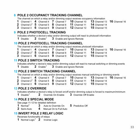
33
8 POLE 2 OCCUPANCY TRACKING CHANNEL The channel on which a relay and/or dimming output receives occupancy information 1 Channel 1 4 Channel 4 7 Channel 7 10 Channel 10 13 Channel 13 16 Channel 16 2 Channel 21 5 Channel 5 8 Channel 8 11 Channel 11 14 Channel 14 3 Channel 3 6 Channel 6 9 Channel 9 12 Channel 12 15 Channel 15 9 POLE 2 PHOTOCELL TRACKING Indicates whether a device’s relay and/or dimming output will react to photocell information 1 Disable 2 Enable1 3 Enable and Ignore Remote
10 POLE 2 PHOTOCELL TRACKING CHANNEL The channel on which a relay and/or dimming output receives photocell information 1 Channel 1 4 Channel 4 7 Channel 7 10 Channel 10 13 Channel 13 16 Channel 16 2 Channel 21 5 Channel 5 8 Channel 8 11 Channel 11 14 Channel 14 3 Channel 3 6 Channel 6 9 Channel 9 12 Channel 12 15 Channel 15 11 POLE 2 SWITCH TRACKING Indicates whether a device’s relay and/or dimming output will react to manual switching or dimming events
1 Disable 2 Enable1 3 Enable and Ignore Remote
12 POLE 2 SWITCH TRACKING CHANNEL The channel on which a relay and/or dimming output receives manual switching or dimming events 1 Channel 1 4 Channel 4 7 Channel 7 10 Channel 10 13 Channel 13 16 Channel 16 2 Channel 21 5 Channel 5 8 Channel 8 11 Channel 11 14 Channel 14 3 Channel 3 6 Channel 6 9 Channel 9 12 Channel 12 15 Channel 15 13 POLE 2 OVERRIDE Indicates whether a device’s relay is forced on/off and/or dimming output is forced to maximum/minimum 1 Disable1 2 Override On Enable 3 Override Off Enable
14 POLE 2 SPECIAL MODE See page 11-12 for detailed definition 1 Normal1 3 Auto to Override On 5 Predictive Off 2 Semi-Auto 4 Manual On to Full Auto 15 INVERT POLE 2 RELAY LOGIC Reverses functionality of relays 1 Normal Logic1 2 Inverse Logic

MANUAL PROGRAMMING
3.2 GATEWAY LCD SCREEN & TOUCH CONTROLS
INSTALLATION
Control Unit and Power Supply1. Mount power supply to a 4” x 4” square junction box (through
a 1/2” knockout)2. Connect the supplys’ class 1 line voltage wires3. Mount nGWY2 CTRL unit to top of same junction box4. Connect the power supplys’ class 2 low voltage wires to the
nGWY2 CTRL’s terminal connectors (polarity insensitive)5. Unit’s LEDs will flash indicating power up.
nGWY2 CTRL
PS 250
BA
CK
FRO
NT
The nGWY2 CTRL and nGWY2 GFX units are powered via a PS 250 power supply wired via each unit’s power terminal connectors. Note: For 347 VAC powering, dual PS 150 347 power supplies are provided. Be sure to connect the red power output wires from the PS 150 347 supplies together and then wire to both the nGWY2 GFX and nGWY2 CTRL units.
nGWY2 GFX
nGWY2 CTRL
nGWY2 GFX
nGWY2 CTRL
120-277 VAC Wiring 347 VAC Wiring

35
Gateway Touch Screen1. Before mounting Gateway Touch Screen (nGWY2 GFX), connect Class 2
low voltage wires from power supplies to unit’s power terminal connections (polarity insensitive
2. Verify unit has power by observing screen and/or LED3. Connect CAT-5 cable(s) from nGWY2 CTRL to one of the RJ-45 port(s) on
rear of nGWY2 GFX unit4. Verify units are communicating (indicated by on-screen blinking heart icon)5. Mount unit to standard single gang switch box (screws provided)6. Pressing reset button twice is equivalent to repowering unit
Note - to reset touch screen calibration, press reset button (located on left side of unit) 3x to restart unit in screen-calibration mode.
OVERVIEWThe touch screen on the Gateway (nGWY2 GFX) can be used to perform many tasks, including:
• View/Edit Gateway device settings • View complete network tree of downstream nLight Enabled devices • View operational status of any connected nLight-enable device • View complete list of control profiles • View list of currently running control profiles • Run a control profile on demand
DEFAULT LCD SCREEN SECURITY PIN NUMBER
[1] [2] [3] [4]

A WallPod’s broadcasting channel setting(s) can be changed manually. The following instructions apply to all WallPods except the Scene Controller (nPODS).
VERIFY CURRENT CHANNEL:Using a steady cadence press the corners of the button portion of the WallPod in the following sequence:
3, 4, 3, 4, 1, 2, 1, 2 Wait approximately 3 seconds and the light will cycle (flash) the number of times indicating the current channel setting. (i.e., Lights will cycle twice if current setting is channel 2)
CHANGE CURRENT CHANNEL:Using a steady cadence press the corners of the button portion of the nPOD in the following sequence:
3, 4, 3, 4, 1, 2, 1, 2Wait approximately 3 seconds and the light will cycle (flash) the number of times indicating the current channel setting (i.e., Lights will cycle twice if current setting is channel 2).
Immediately after the lights cycle the current settings, select the corner corresponding to the channel on which you would like the WallPod to broadcast (i.e., bottom left for channel 3). The lights will then cycle according to the channel that has been selected.
1 2
3 4
1 2
3 4
1 2
3 4
MANUAL PROGRAMMING
3.4 nPOD

37
PLEASE READ ALL 4 STEPS BEFORE PROGRAMMING1. Enter B-Level programming mode by holding down
uppermost left button until LED flashes rapidly, release, then hold down until rapid flash again, release, then immediately enter programming function as described in step 2.
2. Enter a programming function by pressing button the number of times as the desired function number from the B-Level function table below (e.g., press ten times for function 10, Switch Broadcast Channel - Pole 1).
3. The selected function’s current setting will then be read out in a sequence of LED flashes (e.g., one flash for Channel 1). To change setting, proceed to step 4 before sequence repeats 3 times.
4. While the sensor is flashing back current setting, interrupt it by pressing button the number of times for the new desired setting as indicated in the particular function’s detailed table (e.g., press twice for Channel 2). Sensor will begin to flash new setting as confirmation.
Note: To exit B-Level programming mode or to change to a different function, wait for blink back sequence to repeat 3 times then return to step 1.
nPODM PROGRAMMING INSTRUCTIONS
For more manual programming, refer to the nLight Push-Button WallPod Programming Instruction Card:
http://www.sensorswitch.com/instructionfiles/IN-11.1.pdf

4 REMOTE PROGRAMMING VIA SENSORVIEW™
SensorView is used to perform the following start-up tasks:• Verify discovery of Gateway and all devices• Set-up user accounts• Label ports with zone names• Edit active defaults in units (time delays, set-points, modes)• Perform any necessary firmware updates (extended time may be
required) • Create Groups/Profiles per customer requests• Print Inventory and Profile reports• Perform system backup
To install SensorView, download and follow the SensorView Installation Guide:
http://docs.nlightcontrols.com/installation/sensorview
http://www.sensorswitch.com/nlight/docs/install.pdf

39
5 HARDWARE TROUBLESHOOTING AIDS
SENSOR LEDS• If no LED flashes are present (even when push-button is pressed) there
is no sensor power. Check CAT5e cable for connectivity.• If LED repeatedly rapid flashes, and then blinks 2 times, power is present
but communication is not present. Check CAT5e cable for connectivity.• One second of rapid flashing followed by four blinks: Legacy device in
local zone which is not compatible with this device.
BRIDGE PORT LEDS• No LED blinks indicates bad cabling• Rapid blinks indicates discovery is occurring• Persistent and/or periodic rapid flashing means communications issue
is present (short, cross)• Activity Mode (default)
a Single blink indicates normal polling traffic of zone b Double blink indicates upstream Gatewayc 3 blinks indicates upstream Bridged 4 blinks indicates downstream Bridgee 5 blinks indicates that discovery on a port has been locked out due to
inconsistent communication with a downstream devicef 6 blinks indicates there is a local wiring loop between bridge ports
(Bridge discovered itself)• Device Count Mode (press button once to toggle between modes)
Number of detected devices is blinked out in two digits (fast blinking is zero)
POWER PACK LEDS• Interior LED will be solid if it is polling the zone (e.g., Gateway or Bridge
not connected)• Only one per zone at any time should be polling• Exterior LED will blink at regular pace to indicate communication• If either port repeatedly rapid flashes, and then blinks 3 times, there is
low voltage on the connected cable (commonly caused by miswiring) • If interior LED repeatedly rapid flashes, and then blinks 2 times,
communication is not present

HARDWARE TROUBLESHOOTING AIDS CONT
GATEWAY Rediscovery
Gateway can be manually forced to rediscover all network devices a From LCD screen on Gateway (Main Menu > Commissioning): - Press the Lock button - Type [1][2][3][4] then hit Enter - Gateway Setup - Rediscover all devices orb Cycle power then disconnect Power Supply
BRIDGE RESET
a Press and hold button for 6 seconds orb Cycle power (unplug all ports first) then disconnect Power Supply
POWER PACK SHUT DOWN MODEIf a CAT5e is wired incorrectly such that a power line is connected to a data line, an nPP-16 power pack will go into a protective shut down mode and will appear dead. Once both the incoming CAT5e connections have been cable tested and the initial miswiring problem is fixed, the power pack can only be brought back to life by removing line voltage from it (either disconnecting it, or by resetting the circuit). Both should be done with no CAT5e connections present so that it is assured that no power is being supplied from another device.

41
BUTTON MODE
• Enables a device’s push-button to toggle the device’s internal relay(s) or change the dim level from full bright to full dim
• Mode is present in any device with a relay (power packs, line voltage sensors, etc.) and any device with a dimming output (nCM ADC, nCM PDT D, nPODM DX, nIO D, etc.)
To Enable1 Push button down until LED flashes rapidly.2 Release Button.3 Press Button 1 time.4 Short pause (2 seconds), then press button 5 times to enable toggle switch mode.5 Press Button down until LED Flashed Rapidly.6 Release Button.7 Press Button 1 time.8 The LED will flash twice indicating acceptance of NEW Setting.
To Disable 1 Push button down until LED flashes rapidly.2 Release Button.3 Press Button 1 time.4 Short pause (2 seconds), then press button 4 times to disable toggle switch mode.5 Press Button down until LED Flashes Rapidly.6 Release Button.7 Press Button 1 time.8 The LED will flash twice indicating acceptance of NEW Setting.
Note: When button mode is enabled, it may take several seconds for the lights to respond to the on/off command.
