hariis truepoint 4000 - the radio installation
TRANSCRIPT

8/10/2019 Hariis TRuepoint 4000 - The Radio Installation
http://slidepdf.com/reader/full/hariis-truepoint-4000-the-radio-installation 1/118
Microwave Digital Radios
TRuepoint 4
7 to 38 GHz
The Radio Installation
P/N IMN-904007-E02

8/10/2019 Hariis TRuepoint 4000 - The Radio Installation
http://slidepdf.com/reader/full/hariis-truepoint-4000-the-radio-installation 2/118

8/10/2019 Hariis TRuepoint 4000 - The Radio Installation
http://slidepdf.com/reader/full/hariis-truepoint-4000-the-radio-installation 3/118
TR UEPOINT™ 4000 SERIES
THE R ADIO INSTALLATIONPART NO. IMN-904007-E02
JULY 2005

8/10/2019 Hariis TRuepoint 4000 - The Radio Installation
http://slidepdf.com/reader/full/hariis-truepoint-4000-the-radio-installation 4/118
Revision history
Issue date Status Description of change / revision
February 28, 2005 PCO 24157 • First release
July 14, 2005 ECO 25075• Added 7-8 GHz frequencies to product offering• General Update, including RFU type pictorial changes
(TR5100 to TR4100)
Part Nº IMN-904007-E02© Copyright 2005 HARRIS CORPORATION. All rights reserved.
TRuepoint™, MicroStar®, NetBoss™, and STARVIEW™ are trademarks ofHARRIS CORPORATION
Data subject to change without notice.
Harris Corporation -Microwave Communications Division
637, Davis Drive
Morrisville, NC 27560, USA
Phone: 1-800-227-8332
Fax: 1-919-767-3233
Harris Corporation -Microwave Communications Division
3, rue de l’Hôtel de VilleDollard-des-Ormeaux, Québec,
Canada H9B 3G41-800-227-8332 or 1-514-421-8400
FAX: 1-514-421-3555

8/10/2019 Hariis TRuepoint 4000 - The Radio Installation
http://slidepdf.com/reader/full/hariis-truepoint-4000-the-radio-installation 5/118
Harris Corporation TRuepoint™ 4000 Radio Installation
WARNING
Making adjustments and/or modifications to this equipment that are not inaccordance with the provisions of this instruction manual or othersupplementary documentation may result in personal injury or damage tothe equipment, and may void the equipment warranty.
AVERTISSEMENT
Tout réglage ou modification faits à cet équipement hors du cadre édictépar ce guide d’utilisation ou par toute autre documentation supplémentairepourraient causer des blessures ou endommager l’équipement et peutentraîner l’annulation de sa garantie.
WARNUNG
Die an diesen Geräten gemachte Einstellungen und/oder Änderungen,welche nicht gemäß dieser Bedienungsanleitung, oder gemäß anderenzusätzlichen Anleitungen, ausgeführt werden, können Verletzungen oderMaterialschäden zur Folge haben und eventuell die Garantie ungültigmachen.
ATENCIÓN
Llevar a cabo ajustamientos y/o modificaciones a este equipo, sin seguirlas instrucciones provistas por este manual u otro documento adicional,podría resultar en lesiones a su persona o daños al equipo, y anular lagarantía de este último.

8/10/2019 Hariis TRuepoint 4000 - The Radio Installation
http://slidepdf.com/reader/full/hariis-truepoint-4000-the-radio-installation 6/118
TRuepoint™ 4000 Radio Installation July 2005

8/10/2019 Hariis TRuepoint 4000 - The Radio Installation
http://slidepdf.com/reader/full/hariis-truepoint-4000-the-radio-installation 7/118
TRuepoint™ 4000 Radio Installation Harris Corporation
CONTENTS
PREFACEISO 9001 Certification ................................................................................. -vTechnical Assistance Center ......................................................................... -v
CHAPTER 1, SCOPE OF THIS MANUALForeword .................................................................................................... 1-1
Using this Manual ..................................................................................... 1-1Structure of this Manual............................................................................. 1-2Key Features of the TRuepoint™ 4000 Radio................................................. 1-3Related Manuals ...................................................................................... 1-4
CHAPTER
2, GENERAL
DESCRIPTION
The TRuepoint™ 4000 RFU ............................................................................ 2-1The TRuepoint™ 4000 SPU ............................................................................ 2-4General Specifications .................................................................................. 2-5
CHAPTER 3, INSTALLING THE RFUGeneral ...................................................................................................... 3-1
Scope...................................................................................................... 3-1Site Requirements .................................................................................... 3-1Qualifications of Installation Personnel ......................................................... 3-2Installation Types of the RFU...................................................................... 3-2
Installing the RFU Outdoors — the Detachable Mount ........................................ 3-3
Assemble the antenna ........................................................................... 3-5Set the antenna polarization — 13-38 GHz Radio ...................................... 3-6Set the antenna polarization — 7-8 GHz Radio.......................................... 3-8Mount the antenna to the mast............................................................. 3-10Latch the RFU to the antenna ............................................................... 3-11Install the coaxial cable from the RFU to the SPU .................................... 3-12Ground the RFU and the Coaxial Cable................................................... 3-14
Installing the RFU Outdoors — the Separate Mount ......................................... 3-16Attach the mounting hardware to a pipe ................................................ 3-18Mount the RFU on the mounting hardware.............................................. 3-19Connect the waveguide between the RFU and the antenna ....................... 3-20Install an “N” type connector on one end of the coaxial cable.................... 3-21Install the coaxial cable ....................................................................... 3-22
Ground the RFU and the coaxial cable.................................................... 3-24

8/10/2019 Hariis TRuepoint 4000 - The Radio Installation
http://slidepdf.com/reader/full/hariis-truepoint-4000-the-radio-installation 8/118
TRuepoint™ 4000 Radio Installation July 2005
TOC-ii Contents
CHAPTER 4, INSTALLING THE SPUGeneral ...................................................................................................... 4-1Procedure ................................................................................................... 4-3
Install the SPU in the rack...................................................................... 4-3Connect the Coaxial Cables to the SPU .................................................... 4-5Ground the SPU.................................................................................... 4-7Connect power to the SPU...................................................................... 4-8Connect the MUX Tributaries ................................................................ 4-11Connect remote and local communications equipment ............................. 4-15Connect other SPUs in repeater or spur configuration .............................. 4-16If required, connect alarm relays and auxiliary alarm inputs ..................... 4-17Switch ON power to the SPU ................................................................ 4-17Configure the radio ............................................................................. 4-18Fine align the antenna......................................................................... 4-18Check for alarms and verify the functionality .......................................... 4-21
CHAPTER 5, MAINTENANCEMaintenance ............................................................................................... 5-1
Basic Troubleshooting................................................................................ 5-1Replacing Units ............................................................................................ 5-3
Replacing the RFU..................................................................................... 5-3Remove the RFU................................................................................... 5-3Install a new RFU.................................................................................. 5-5
Replacing the SPU..................................................................................... 5-6
CHAPTER 6, OPTIONS AND ORDERINGOrdering ..................................................................................................... 6-1
Part Numbers Versus Product Codes............................................................ 6-1Spare Unit Ordering Information................................................................. 6-1
Placing the order .................................................................................. 6-2Customer Service Information ..................................................................... 6-17
Standard Customer Service Support Guidelines........................................... 6-17Services Offered ..................................................................................... 6-17Technical Assistance Centre ..................................................................... 6-18Repair and Returns Services..................................................................... 6-18On-Site Field Service Support................................................................... 6-18Annual Repair Service Program (ARSP)...................................................... 6-19Maintenance Level Agreements (MLA)........................................................ 6-19Customer Training .................................................................................. 6-19
CHAPTER 7, GLOSSARY
INDEX

8/10/2019 Hariis TRuepoint 4000 - The Radio Installation
http://slidepdf.com/reader/full/hariis-truepoint-4000-the-radio-installation 9/118
Harris Corporation TRuepoint™ 4000 Radio Installation
PREFACE
ISO 9001 Certification
The Harris Microwave Communications Division is committed to totalcustomer satisfaction and is I.S. EN ISO 9001: 2000 registered for the design,manufacture, installation and service of microwave radio products andsystems.
Technical Assistance Center
Our Technical Assistance Center (TAC) is staffed with factory trained andhighly qualified Product Support staff whose task is to provide telephonesupport to resolve complex customer equipment problems quickly andaccurately in a timely manner. Customers who completed product traininggiven by Harris Microwave Communications Division and are equipped withproper test equipment and spare parts will experience quick resolution of theirequipment problems.
Harris Corporation — Microwave Communications Division
637 Davis Drive
Morrisville, NC 27560, USA Phone: 1-800-227-8332
(Outside North America: 1 514-421-8333)
Email: [email protected]
Harris Corporation — Microwave Communications Division
3 Hotel-de-Ville
Dollard-des-Ormeaux, Quebec
Canada H9B 3G4
Phone: 1-800-227-8332 or 1-514-421-8333
Fax: 1-514-685-4580
Email: [email protected] (point-to-point) [email protected] (point-to-multipoint)

8/10/2019 Hariis TRuepoint 4000 - The Radio Installation
http://slidepdf.com/reader/full/hariis-truepoint-4000-the-radio-installation 10/118
TRuepoint™ 4000 Radio Installation July 2005
vi Preface
Harris S.A. de C.V.
Boulevard Manuel Avila Camacho #36 Piso 17
Col. Lomas de Chapultepec
C.P. 11000Torres Esmeralda II
Mexico D.F.
Phone:+52-55-5-249 3700 or 800-872-0061
Fax: +52-55-5-249 3701 & 02
Email: [email protected]
Orbecom c/o Harris Microwave Division
Calle 101, No. 44-58
Bogota, Colombia
Phone:+57-1-533-0912
Email: [email protected]
Harris do Brasil
Edifício STADIUM
Al. Rio Negro 1030
Conjuntos 202/204/206
CEP 06454-000
Alphaville
Barueri - SP
Phone:+55-11-4197-3000
FAX: +55-11-4197-3001
Email: [email protected]
Coasin Communicaciones S.A.
Adolfo Alsina, 1322
(C1088AAJ) Buenos Aires
Argentina
Phone:+54-11-4383-0074
Fax: +54-11-4383-0075
Email: [email protected]
Harris Communication France S.A.S.
Centrale Parc
Avenue Sully Prud’homme92298 Chatenay-Malabry-France
France
Phone: +33- 1-55-52-8080 or 800-55-52-8080
Fax: +33-1-55-52-8012
Email: [email protected]

8/10/2019 Hariis TRuepoint 4000 - The Radio Installation
http://slidepdf.com/reader/full/hariis-truepoint-4000-the-radio-installation 11/118
Harris Corporation TRuepoint™ 4000 Radio Installation
vii
Harris Communications (Shenzhen)
R3-B2 High Tech. Industrial Park
Nanshan District, Shenzhen 518057
The People’s Republic of ChinaPhone: +86-755-2663-7928
Fax: +86-755-2663-7048
Trisilco Folec
36-1 Jalan PJU 8/5B, Perdana Business Centre
Bandar Damansara Perdana
47820 Petaling Jaya
Selangor Darul Ehsan
Malaysia
Phone: +60-3-7728-8228 ext. 8319
Fax: +60-3-7722-2826Email: [email protected] or [email protected]
Harris Microwave Customer Support
Harris provides world-class service for all our valued customersincluding 24/7 technical support. Your priority calls are handled
through our Technical assistance Center (TAC):
Call: 800-227-8332
(outside North America 514-421-8333)
You can also contact us through e-mail at:
Registered customers can obtain key product indformation on ourPremier Web Site at: https://premier.harris.com/microwave

8/10/2019 Hariis TRuepoint 4000 - The Radio Installation
http://slidepdf.com/reader/full/hariis-truepoint-4000-the-radio-installation 12/118
T e c h n i c a l
A s s i s t a n c e
C e n t e r
Dear Customer,To facilitate warranty support and to receive product updateinformation, please register on the Harris MCD Premier Customerwebsite:
https://premier.harris.com/microwave
If you are unable to register online, please complete and returnthe form at the bottom of the page to our customer servicedepartment.
By Fax: 514-421-3555
By email: [email protected]
By mail: Harris CorporationMicrowave Communications Division3 Hotel de VilleDollard-des-Ormeaux, QuebecCANADA H9B3G4
PLEASE PRINT:
Company Name:
Requestor's Name:
Title:
Address:
City:
ZIP/Postal Code:
Telephone Number:
Email:
Original Sales Order/PO Number:
Dept:
State/Province:
Country:
Fax Number:
Sales order numbers are found in your documentation and are stencilled on the equipment rack base plate,for example, A44044A1.

8/10/2019 Hariis TRuepoint 4000 - The Radio Installation
http://slidepdf.com/reader/full/hariis-truepoint-4000-the-radio-installation 13/118
Harris Corporation TRuepoint™ 4000 Radio Installation
C H A P T E R
1SCOPE OF THIS MANUAL
Foreword
This document provides instructions for installing the TRuepoint™ 4000 radioterminal, according to planned or acquired options. It also providesinformation on
• Cable connections to the SPU;
• General Setup information,
• Grounding guidelines; and
• Basic troubleshooting.
This document is subject to change without notice.
Using this Manual
This manual has been optimized for fast Web viewing, and text shown in thisformat identifies navigation links leading to locations that are internal orexternal to the manual.

8/10/2019 Hariis TRuepoint 4000 - The Radio Installation
http://slidepdf.com/reader/full/hariis-truepoint-4000-the-radio-installation 14/118
TRuepoint™ 4000 Radio Installation July 2005
1-2 Scope of this Manual
Structure of this Manual
Besides this introductory Chapter, this Manual contains the following:
Chapter 2, General Description
A closer look at the TRuepoint™ 4000 Radio and options. GeneralSpecifications and System Compliance to known Standards are also covered.
Chapter 3, Installing the RFU
Provides steps for installing the RFU, and the required cable connections forgrounding, general Setup and replacing the RFU.
Chapter 4, Installing the SPU
Provides steps for installing the SPU, and the required cable connections for ageneral Setup, as well as basic information on configuration andtroubleshooting.
Chapter 5, Maintenance
Steps for replacing the RFU, and the SPU.
Chapter 6, Options and Ordering
Ordering field replaceable units and Customer Service information.
Chapter 7, Glossary
Compilation of acronyms and special terms — and their definitions, whereappropriate — used throughout the TRuepoint™ user documentation.
Appendix A, SPU Ports’ Pinouts
Pinout description of the configurable ports on the TRuepoint™ 4000 SPU.
8/10/2019 Hariis TRuepoint 4000 - The Radio Installation
http://slidepdf.com/reader/full/hariis-truepoint-4000-the-radio-installation 15/118
Harris Corporation TRuepoint™ 4000 Radio Installation
1-3
Key Features of the TRuepoint™ 4000 Radio
• Capacity independent RFU
• RF independent SPU
• Fully programmable modem
• 1 RMS SPU for 1+0
• In-service performance monitoring with parameters compliant toITU-T G.826 recommendations
• Self diagnostics to differentiate the path alarms from the equipmentalarms
• History and event logs
• Optional digital orderwire
• Built-in agent to support SNMP protocol
• Programmable relay contacts for alarm indication / site control• Site alarms monitoring
• Web CIT for radio maintenance
• Built-in HDLC interface for compatibility with existing MicroStar® M/H and L products
• Remote tributary loopback
• Local tributary loopback
• MUX to DEMUX loopback
• Digital IF loopback
• RTPC, DTPC and ATPC operation

8/10/2019 Hariis TRuepoint 4000 - The Radio Installation
http://slidepdf.com/reader/full/hariis-truepoint-4000-the-radio-installation 16/118
TRuepoint™ 4000 Radio Installation July 2005
1-4 Scope of this Manual
Related Manuals
Manual P/N Title Comments
Top Level
IMN-904006-Exx System Description
Top level document providing a broadoverview of the TRuepoint™ 4000 platform.Includes Theory of Operation, GeneralSpecifications, and Performance Tables.
User Manuals (recommended order of use)
IMN-904007-Exx Radio Installation This document
IMN-904008-Exx Operator’s InterfaceProvides advanced system configuration,monitoring, control and troubleshootinginformation.
Quick ReferenceQRC-904009-Exx Quick Reference Card
Provides a graphical representation of theTRuepoint™ software menus.

8/10/2019 Hariis TRuepoint 4000 - The Radio Installation
http://slidepdf.com/reader/full/hariis-truepoint-4000-the-radio-installation 17/118
Harris Corporation TRuepoint™ 4000 Radio Installation
C H A P T E R
2GENERAL DESCRIPTION
The TRuepoint™ 4000 RFU
Fins
(radial)for heat dissipation
4 Hooksfor attaching theRFU to the antennainterface latches
Carrying Handle
Antenna Portfor connecting a flexiblewaveguide to an antenna,or mounting directly to anantenna feed boom
Back View Front View
Engraved Arrowpointing to the RFU position forvertical polarization

8/10/2019 Hariis TRuepoint 4000 - The Radio Installation
http://slidepdf.com/reader/full/hariis-truepoint-4000-the-radio-installation 18/118
TRuepoint™ 4000 Radio Installation July 2005
2-2 General Description
Figure 2-1: RFU in the Separate Mount Configuration
Flexible WaveguideFlange, per Table 2-1
Offset Pole-Mount
Antenna Feed Boom
Antenna(Standard, not equipped withlatches for engaging the RFU)
RFU MountingPlate Assembly
Antenna Interface

8/10/2019 Hariis TRuepoint 4000 - The Radio Installation
http://slidepdf.com/reader/full/hariis-truepoint-4000-the-radio-installation 19/118
Harris Corporation TRuepoint™ 4000 Radio Installation
2-3
Figure 2-2: RFU in the Detachable Mount Configuration
Special Antennaequipped with
4 Latchesfor engaging the RFU hooks
Offset Pole-Mount
Detachable RFU
See Bottom View
Female N-type: connectstraffic, telemetry andpower from the SPU
Female BNC:RSSI Test point
Bottom View
4 Latches
Grounding stud,with hex nut

8/10/2019 Hariis TRuepoint 4000 - The Radio Installation
http://slidepdf.com/reader/full/hariis-truepoint-4000-the-radio-installation 20/118
TRuepoint™ 4000 Radio Installation July 2005
2-4 General Description
The TRuepoint™ 4000 SPU
Figure 2-3: Identifying the Ports, (Option 201-904010-004)
Figure 2-4: Identifying the Ports, (Option 201-904010-002)
RFU Cable N-TypeConnector
Grounding lug
SUM
SPURFUCable
LEDs
PowerBreaker
2W
Relay / Alarms
Tributaries 9-16
Tributaries 1-8
10/100BASE-T 2
10/100BASE-T 1
HDLC
Port 2
NTWRK/LAN 2
4W
Port 1
NTWRK/LAN 1
Battery Port
RFU Cable N-TypeConnector
Grounding lug
SUM
SPURFUCable
LEDs
PowerBreaker
2W
Relay / Alarms
Tributaries 1-8
10/100BASE-T 2
10/100BASE-T 1
HDLC
Port 2
NTWRK/LAN 2
4W
Port 1
NTWRK/LAN 1
Battery Port
8/10/2019 Hariis TRuepoint 4000 - The Radio Installation
http://slidepdf.com/reader/full/hariis-truepoint-4000-the-radio-installation 21/118
Harris Corporation TRuepoint™ 4000 Radio Installation
General Specifications 2-5
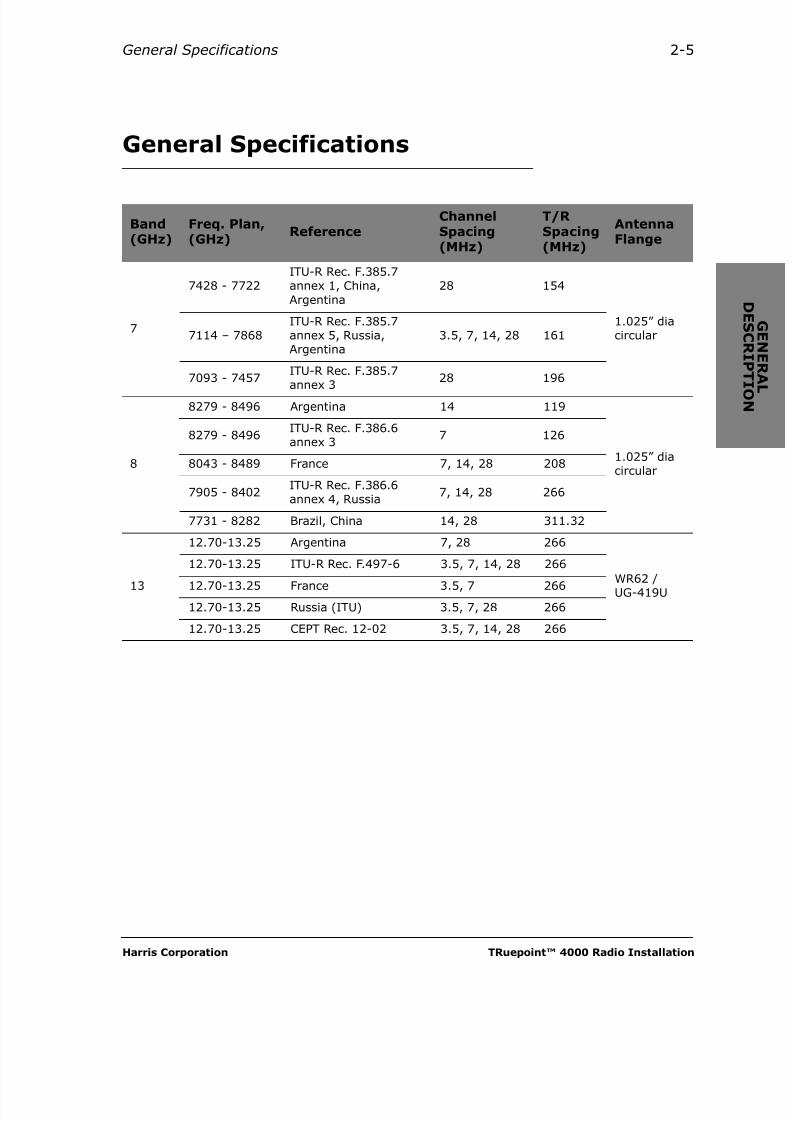
General Specifications
Band(GHz)
Freq. Plan,(GHz) Reference
ChannelSpacing(MHz)
T/R Spacing(MHz)
AntennaFlange
7
7428 - 7722ITU-R Rec. F.385.7annex 1, China,Argentina
28 154
1.025” diacircular7114 – 7868
ITU-R Rec. F.385.7annex 5, Russia,Argentina
3.5, 7, 14, 28 161
7093 - 7457ITU-R Rec. F.385.7
annex 3
28 196
8
8279 - 8496 Argentina 14 119
1.025” diacircular
8279 - 8496ITU-R Rec. F.386.6annex 3
7 126
8043 - 8489 France 7, 14, 28 208
7905 - 8402ITU-R Rec. F.386.6annex 4, Russia
7, 14, 28 266
7731 - 8282 Brazil, China 14, 28 311.32
13
12.70-13.25 Argentina 7, 28 266
WR62 /UG-419U
12.70-13.25 ITU-R Rec. F.497-6 3.5, 7, 14, 28 266
12.70-13.25 France 3.5, 7 266
12.70-13.25 Russia (ITU) 3.5, 7, 28 266
12.70-13.25 CEPT Rec. 12-02 3.5, 7, 14, 28 266

8/10/2019 Hariis TRuepoint 4000 - The Radio Installation
http://slidepdf.com/reader/full/hariis-truepoint-4000-the-radio-installation 22/118
TRuepoint™ 4000 Radio Installation July 2005
2-6 General Description
Band(GHz)
FrequencyRange(GHz)
ReferenceChannelSpacing(MHz)
T/R Spacing(MHz)
AntennaFlange
15
14.40-15.35 ITU-R Rec. F.636-3 3.5, 7, 14, 28 490
WR62 /UG-419U
14.40-15.35 Russia (ITU) 14, 28 490
14.50-15.35 ITU-R Rec. F.636-3 3.5, 7, 14, 28 420
14.50-15.35 Russia (ITU) 14, 28 420
14.627-16.243
Mexico 3.5, 7, 14, 28 315
14.50-15.343 Argentina 7, 14 728
14.50-15.343 CEPT Rec. 12-07 3.5, 7, 14, 28 728
14.50-15.348 Brazil Res. 129 3.5, 7, 14 420
14.50-15.348 China 3.5, 7, 14, 28 420
14.501-15.343
BAPT 211ZV 038/15 GHz
3.5, 7, 14 728
14.50-15.35On request only 3.5, 7, 14, 28
475
14.50-15.35 640
18
17.70-19.70
ITU-R Rec. F.595-6Co-channelarrangementInterleaved arrang.
27.5 1010
WR42 /UG-595U
17.70-19.70 Mexico 27.5 1615
17.70-19.70 Russia (ITU) 27.5 101017.70-19.70 Rec.12-03, France 13.75, 27.5 1010
17.70-19.70ITU Rec. F 595-Annex 3 (UK)
3.5 1008
17.70-19.70
ITU Rec. F 595-6Annex 4Co-channel andinterleaved arrang.
27.5(interleave)
1010
17.70-19.70ITU Rec. F 595-6Annex 5
3.5, 7 1010
17.70-19.70Brazil, Norma 15/96(On request only)
27.5 1560
8/10/2019 Hariis TRuepoint 4000 - The Radio Installation
http://slidepdf.com/reader/full/hariis-truepoint-4000-the-radio-installation 23/118
Harris Corporation TRuepoint™ 4000 Radio Installation
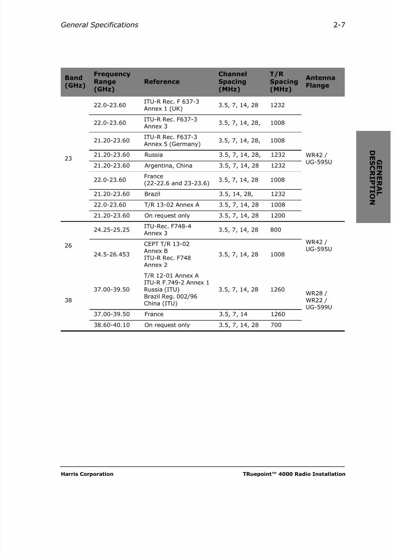
General Specifications 2-7
Band(GHz)
FrequencyRange(GHz)
ReferenceChannelSpacing(MHz)
T/R Spacing(MHz)
AntennaFlange
23
22.0-23.60ITU-R Rec. F 637-3Annex 1 (UK)
3.5, 7, 14, 28 1232
WR42 /UG-595U
22.0-23.60ITU-R Rec. F637-3Annex 3
3.5, 7, 14, 28, 1008
21.20-23.60ITU-R Rec. F637-3Annex 5 (Germany)
3.5, 7, 14, 28, 1008
21.20-23.60 Russia 3.5, 7, 14, 28, 1232
21.20-23.60 Argentina, China 3.5, 7, 14, 28 1232
22.0-23.60France(22-22.6 and 23-23.6)
3.5, 7, 14, 28 1008
21.20-23.60 Brazil 3.5, 14, 28, 1232
22.0-23.60 T/R 13-02 Annex A 3.5, 7, 14, 28 1008
21.20-23.60 On request only 3.5, 7, 14, 28 1200
26
24.25-25.25ITU-Rec. F748-4Annex 3
3.5, 7, 14, 28 800
WR42 /UG-595U
24.5-26.453
CEPT T/R 13-02Annex BITU-R Rec. F748Annex 2
3.5, 7, 14, 28 1008
3837.00-39.50
T/R 12-01 Annex AITU-R F.749-2 Annex 1
Russia (ITU)Brazil Reg. 002/96China (ITU)
3.5, 7, 14, 28 1260 WR28 /WR22 /UG-599U
37.00-39.50 France 3.5, 7, 14 1260
38.60-40.10 On request only 3.5, 7, 14, 28 700
8/10/2019 Hariis TRuepoint 4000 - The Radio Installation
http://slidepdf.com/reader/full/hariis-truepoint-4000-the-radio-installation 24/118
TRuepoint™ 4000 Radio Installation July 2005
2-8 General Description
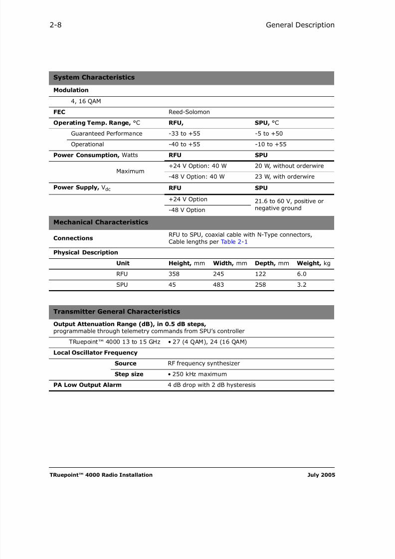
System Characteristics
Modulation
4, 16 QAM
FEC Reed-Solomon
Operating Temp. Range, °C RFU, SPU, °C
Guaranteed Performance -33 to +55 -5 to +50
Operational -40 to +55 -10 to +55
Power Consumption, Watts RFU SPU
Maximum
+24 V Option: 40 W 20 W, without orderwire
-48 V Option: 40 W 23 W, with orderwire
Power Supply, Vdc RFU SPU
+24 V Option 21.6 to 60 V, positive ornegative ground-48 V Option
Mechanical Characteristics
ConnectionsRFU to SPU, coaxial cable with N-Type connectors,Cable lengths per Table 2-1
Physical Description
Unit Height, mm Width, mm Depth, mm Weight, kg
RFU 358 245 122 6.0
SPU 45 483 258 3.2
Transmitter General Characteristics
Output Attenuation Range (dB), in 0.5 dB steps, programmable through telemetry commands from SPU’s controller
TRuepoint™ 4000 13 to 15 GHz • 27 (4 QAM), 24 (16 QAM)
Local Oscillator Frequency
Source RF frequency synthesizer
Step size • 250 kHz maximum
PA Low Output Alarm 4 dB drop with 2 dB hysteresis

8/10/2019 Hariis TRuepoint 4000 - The Radio Installation
http://slidepdf.com/reader/full/hariis-truepoint-4000-the-radio-installation 25/118
Harris Corporation TRuepoint™ 4000 Radio Installation
General Specifications 2-9
Receiver General Characteristics
Operational receive input level at antenna port -20 to –95 dBm
Local oscillator frequency source RF frequency synthesizer
Local oscillator frequency step size 250 kHz maximum
Receiver carrier frequency setting Programmable through telemetry
Slope alarm More than 9 dB/30 MHz or equivalent ratio
Receive overload level without damage -10 dBm
Environmental
Subject Compliance
LightningProtection
Figure 3-10 recommends a protection scheme that uses grounding kits.Harris Corporation recommends that such lightning protection or otheralternatives thereto be provided in compliance to Local and/or NationalElectrical Codes
Temperaturerange
• Full specification: -33o C to + 55o C(meets ETSI EN 300 019-1-3, class 3.1E)
• Operational: -40o C to + 55o C (Operational means that the moduleswill start at cold and traffic will pass without synchronization lossesand BER will be better than 1.0x10⁻⁶ after 15 minutes warm-up)
• Storage: -55o C to + 70o C
Humidity • 5 – 95% non condensing
Altitude • 0 to 5000 m AMSL
Vibration• ETSI EN 300 019-2-4 V2.1.2 (1999-09) class 4.1 -
5 sweep cycles per axis (Stationary, sinusoidal, in-use position)
Transit Vibration• ETSI EN 300 019-2-2 V2.1.2 (1999-09) class 2.3
(random vibration, shocks and drop)
EMI / EMC and Safety Compliance
Subject Compliance
Safety
• IEC 60950-1
• EN 60950-1• EN 60215• EN 60825, Class 1 Laser
EMC
• ETSI EN 301 489-01 V1.4.1 (08-2002) (Part 1: Common technicalrequirements = common part for all radio equipment)
• ETSI EN 301 489-4 (08-2002) (Part 4: Specific conditions for fixedradio links and ancillary equipment and services)

8/10/2019 Hariis TRuepoint 4000 - The Radio Installation
http://slidepdf.com/reader/full/hariis-truepoint-4000-the-radio-installation 26/118
TRuepoint™ 4000 Radio Installation July 2005
2-10 General Description
Tributaries Compliance
Table 2-1: Maximum Allowable Coaxial Cable Length — SPU to RFU
SPU InputVoltage
Low loss RG8U Low loss foam
heliax
Belden 9913 or eq. C2FP or eq. LDF2-50 or eq.
VDC ft. m. ft. m. ft. m.
24 833 254 735 224 1000 305
48 833 254 735 224 1000 305
StandardJitter transfer and jittertolerance requirementCompliance
Output jitterrequirementcompliance
E1 ITU-T G.703 ITU-T G.823 ITU-T G.742
10BASE-T IEEE 802.3 IEEE 802.3 IEEE 802.3
100BASE-T IEEE 802.3 IEEE 802.3 IEEE 802.3

8/10/2019 Hariis TRuepoint 4000 - The Radio Installation
http://slidepdf.com/reader/full/hariis-truepoint-4000-the-radio-installation 27/118
Harris Corporation TRuepoint™ 4000 Radio Installation
C H A P T E R
3INSTALLING THE RFU
General
Scope
This chapter describes the installation procedures applicable to theTRuepoint™ RFU, in the 13-38 GHz frequencies.
Site Requirements
Before starting the following installation procedures, a pipe must be installedon a rooftop or a tower. The pipe diameter must be 115 mm (4.5 in.).
A waterproof entry to the SPU shelter and a good grounding point must also beavailable.

8/10/2019 Hariis TRuepoint 4000 - The Radio Installation
http://slidepdf.com/reader/full/hariis-truepoint-4000-the-radio-installation 28/118
TRuepoint™ 4000 Radio Installation July 2005
3-2 Installing the RFU
Qualifications of Installation Personnel
The installation, maintenance, or removal of antennasystems requires qualified, experienced personnel.Harris installation instructions have been written forsuch personnel. Antenna systems should be inspectedonce a year by qualified personnel to verify properinstallation, maintenance, and condition of theequipment.Installation of the microwave radio and associatedequipment is to be performed by a skilled person. Power
connections to the radio must be made in compliance ofthe local electrical code by a Skilled Person.Harris Corporation disclaims any liability orresponsibility for the results of improper or unsafeinstallation practices.
Installation Types of the RFU
This chapter describes the following installation procedures:
Installing the RFU Outdoors — the Detachable Mount................. 3-3
• RFU directly a t t a c h ed to a pole-mounted antenna.
Installing the RFU Outdoors — the Separate Mount................... 3-16
• RFU mounted on a pole and sepa r a t ed from a pole-mounted antenna
Grounding the RFU and Coaxial Cable ..................................... 3-25
• RFU mounted i n d o o r s on a special bracket attached to a 19-inch rack.

8/10/2019 Hariis TRuepoint 4000 - The Radio Installation
http://slidepdf.com/reader/full/hariis-truepoint-4000-the-radio-installation 29/118
Harris Corporation TRuepoint™ 4000 Radio Installation
Detachable Mount 3-3
Installing the RFU Outdoors —the Detachable Mount
Before starting, check that you have the parts and tools required. The parts areshown in figure 3-1. The tools are listed in table 3-1.
Table 3-1: List of Tools Required for the Installation of the RFU
ToolRequired EquipmentSpecifications Where Used
Miscellaneous tools for
installing connectors on theSPU to RFU coaxial cable.
See the manufacturer documentation
provided with the connector.
• Install the coaxialcable from the RFU
to the SPU, onPage 3-12
Adjustable wrench 11/16" (18 mm) jaws • Throughout
Rope and hook with safetylatch
Common• To bring equipment
up the pipe.
Follow the instructions of the antenna manufacturer
that are enclosed with the antenna for the exact detailsof how to assemble, install, and align the antenna.Drawings shown here of the antenna assembly are forreference only and are intended to simply show theorder in which the antenna and the RFU are assembled.
R SL h i g h e r t h a n - 1 0 d B m c o u ld d a m a g e t h e
r e c e iv e r . Fo r s h o r t p a t h l in k s , e n s u r e a t t e n u a t i n gt h e t r a n s m i t o u t p u t p o w e r b y 2 0 d B b ef o r e
i n i t i a t i n g t h e a n t e n n a a l i g n m e n t .

8/10/2019 Hariis TRuepoint 4000 - The Radio Installation
http://slidepdf.com/reader/full/hariis-truepoint-4000-the-radio-installation 30/118
TRuepoint™ 4000 Radio Installation July 2005
3-4 Installing the RFU
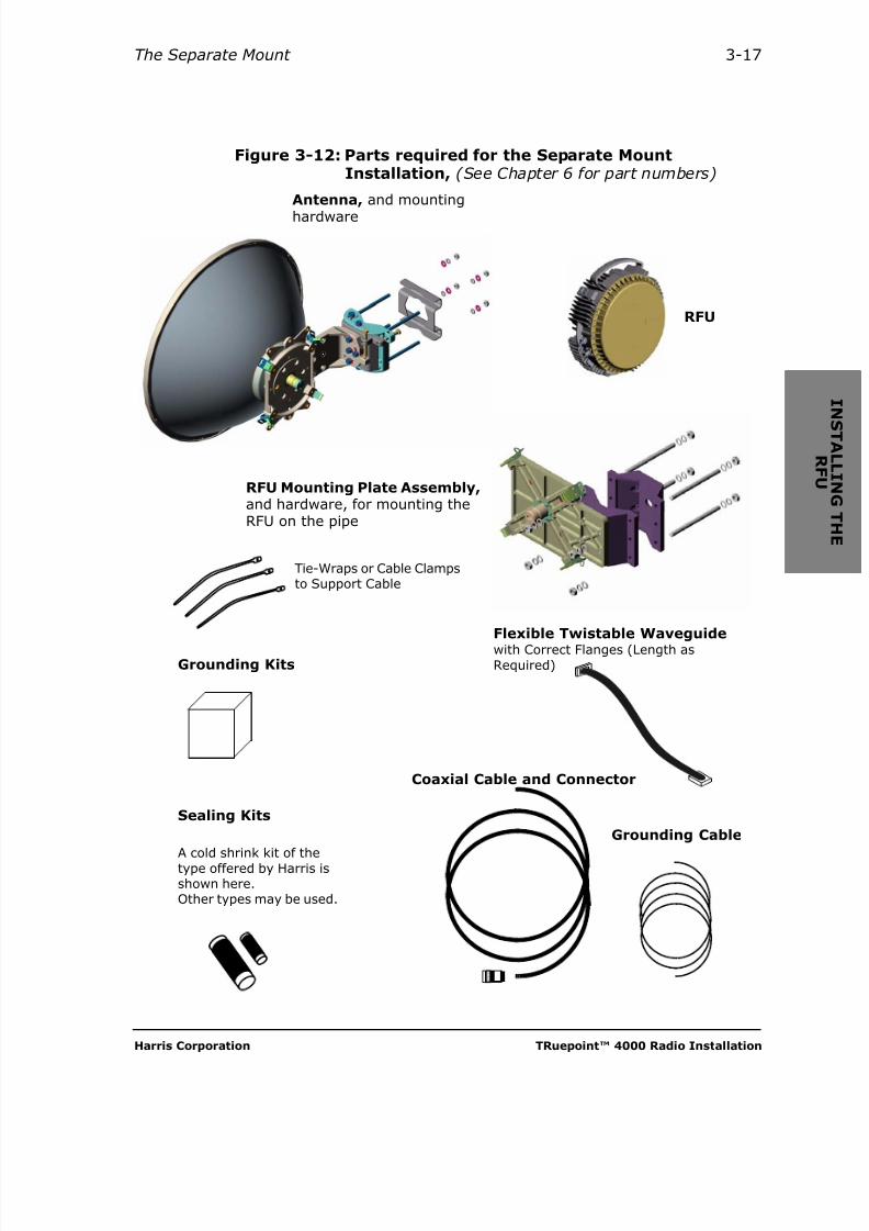
Figure 3-1: Parts required for the Detachable MountInstallation: (See Chapter 6 for part numbers)
RFU
Coaxial Cable and Connector
Tie-Wraps or Cable Clampsto Support Cable
Antenna, equipped for the RFU direct mounting
A cold shrink kit of the
type offered by Harris isshown here.Other types may be used.
Grounding Kits
Sealing Kits
Grounding cable

8/10/2019 Hariis TRuepoint 4000 - The Radio Installation
http://slidepdf.com/reader/full/hariis-truepoint-4000-the-radio-installation 31/118
Harris Corporation TRuepoint™ 4000 Radio Installation
Detachable Mount 3-5
1 Assemble the antenna
Tools and material required
• Common tools
Following the instructions packed with it, assemble the antenna. Please notethat assembly is different depending on whether the antenna is to be to the leftor the right of the pipe.
Figure 3-2: The Parabolic Antenna
8/10/2019 Hariis TRuepoint 4000 - The Radio Installation
http://slidepdf.com/reader/full/hariis-truepoint-4000-the-radio-installation 32/118
TRuepoint™ 4000 Radio Installation July 2005
3-6 Installing the RFU
2 Set the antenna polarization — 13-38 GHz Radio
This procedure is provided as an example, and applieso n l y to the antenna type shown here. Always follow theproper polarization instructions from the provisionedantenna manufacturer.
Tools and material required
• Allen keys, 5 mm and 2 mm (part of the antenna manufacturer’smounting kit)
The polarization of the antenna is controlled by combining the position of theantenna feed boom and a Transition placed on the feed boom.Default position is Vertical, aligning the Engraved Arrow on the RFU with theV-Mark embossed on the Antenna Interface.
Use the following table to determine the action necessary for obtaining therequired polarization.
For setting the Horizontal Polarization, proceed as follows, referring to theTable above, for the relative positions of the Feed boom and Transition:
1. Using the Allen key provided in the kit, loosen the 6 Socket-head screws enough to allow the feed boom to rotate freely.
2. Rotate the feed boom 90 degrees to the r i g h t , or l e f t until it bottoms. (flat
notch pointing right or left, aligned with the H-Mark embossed on theAntenna Interface. Tighten the 6 socket-head screws.
3. Using an Allen key, remove the 2 small socket-head screws on theTransition.
4. Rotate the Transition 45 degrees to the left or right, aligning its screw holesover those of the boom’s face, then replace and tighten the 2 small socket-head screws. Tighten the mall socket-head screws.
PolarizationRotate Relative Position
Refer toFeed boom Transition Flat Notch Slot (Transition)
Vertical No action required Vertical Horizontal Detail A
Horizontal
Right or left — Horizontal Vertical Detail B
—Right or left,45 degrees
HorizontalRotated right orleft, 45 degrees
Detail C
8/10/2019 Hariis TRuepoint 4000 - The Radio Installation
http://slidepdf.com/reader/full/hariis-truepoint-4000-the-radio-installation 33/118
Harris Corporation TRuepoint™ 4000 Radio Installation
Detachable Mount 3-7
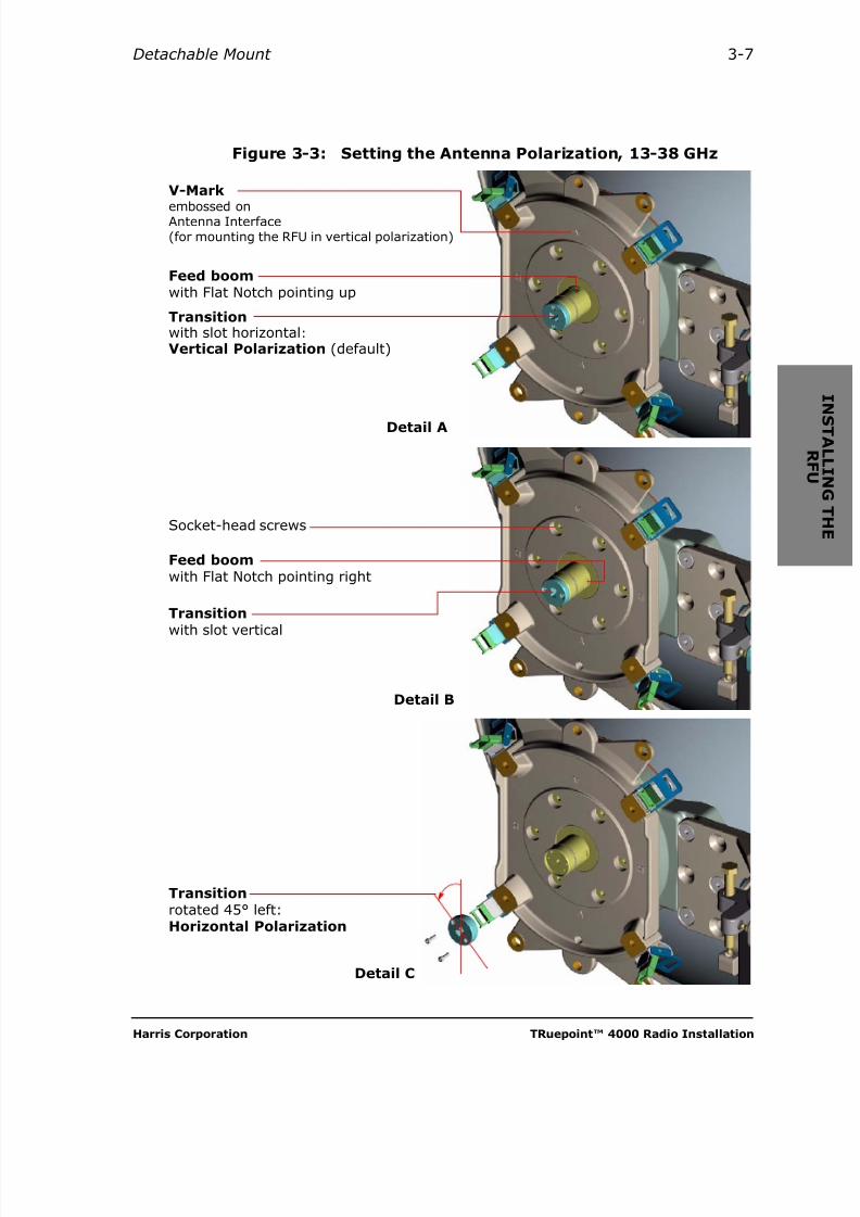
Figure 3-3: Setting the Antenna Polarization, 13-38 GHz
Transitionrotated 45° left:Horizontal Polarization
Feed boomwith Flat Notch pointing up
V-Mark
embossed onAntenna Interface(for mounting the RFU in vertical polarization)
Transitionwith slot horizontal:Vertical Polarization (default)
Feed boomwith Flat Notch pointing right
Socket-head screws
Transition
with slot vertical
Detail A
Detail B
Detail C
8/10/2019 Hariis TRuepoint 4000 - The Radio Installation
http://slidepdf.com/reader/full/hariis-truepoint-4000-the-radio-installation 34/118
TRuepoint™ 4000 Radio Installation July 2005
3-8 Installing the RFU
3 Set the antenna polarization — 7-8 GHz Radio
This procedure is provided as an example, and applieso n l y to the antenna type shown here. Always follow theproper polarization instructions from the provisionedantenna manufacturer.
Tools and material required
• Allen key, 5 mm (part of the antenna manufacturer’s mounting kit)
The polarization of the antenna is controlled by the position of the antenna feed
boom.Default position is Vertical, aligning the Engraved Arrow on the RFU with theV-Label affixed on the Antenna Interface.
Use the following table to determine the action necessary for obtaining therequired polarization.
For setting the Horizontal Polarization, proceed as follows, referring to theTable above, for the relative positions of the Feed boom and AntennaInterface:
1. Using the Allen key provided in the kit, loosen the 4 Socket-head screws enough to allow the Feed boom to rotate freely.
2. Rotate the Feed boom 90 degrees to the r i g h t , or l e f t until it bottoms.(notch pointing right or left, aligned with the H-Label affixed on theAntenna Interface. Tighten the 4 socket-head screws.
PolarizationRotate Relative Position
Refer toFeed boom Notch Slot
Vertical No action required Vertical Horizontal Detail A
Horizontal Right or left Horizontal Vertical Detail B

8/10/2019 Hariis TRuepoint 4000 - The Radio Installation
http://slidepdf.com/reader/full/hariis-truepoint-4000-the-radio-installation 35/118
Harris Corporation TRuepoint™ 4000 Radio Installation
Detachable Mount 3-9
Figure 3-4: Setting the Antenna Polarization, 7-8 GHz
Feed boomwith Notch pointing up
V-Labelaffixed to theAntenna Interface(for mounting the RFU in verticalpolarization)
Feed boomwith slot horizontal:
Vertical Polarization(default)
Notch pointing right
Socket-head screws
Feed boomwith slot verticalHorizontal Polarization
Detail A
Detail B
Shallow cylindrical cavityto rectangular slot, at end of feedboom (Typical)

8/10/2019 Hariis TRuepoint 4000 - The Radio Installation
http://slidepdf.com/reader/full/hariis-truepoint-4000-the-radio-installation 36/118
TRuepoint™ 4000 Radio Installation July 2005
3-10 Installing the RFU
4 Mount the antenna to the mast
Tools and material required
• Adjustable wrenches
Referring to Figure 3-5, and the instructions packed with the antenna, mountthe antenna onto the antenna mast. Tighten the bolts finger-tight.
Figure 3-5: Mounting the Antenna to the mast
19 to 22 N • m
All nuts
(14 to 16 lbf-ft.)
8/10/2019 Hariis TRuepoint 4000 - The Radio Installation
http://slidepdf.com/reader/full/hariis-truepoint-4000-the-radio-installation 37/118
Harris Corporation TRuepoint™ 4000 Radio Installation
Detachable Mount 3-11
5 Latch the RFU to the antenna
Tools and material required
• Adjustable wrench
• Antenna alignment kit (optional)
R em o v e i n f o r m a t i o n t a g a n d c a p , t h e n a p p l y
m o d e r a t e l y s i l i c o n e g r e a s e t o t h e w h o l e f e ed
b o om a r e a , b u t n o t t o i t s f a c e . Fa i lu r e t o d o s o ,
w i l l c au s e t h e RFU t o j a m .
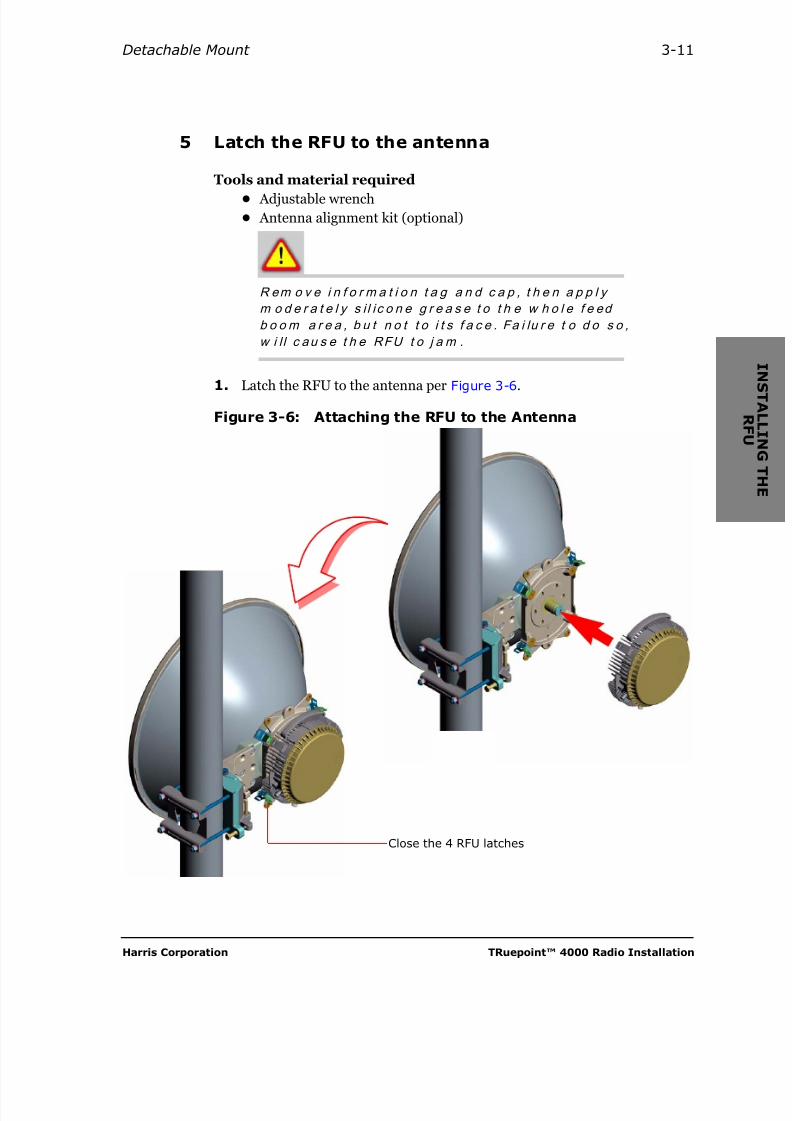
1. Latch the RFU to the antenna per Figure 3-6.
Figure 3-6: Attaching the RFU to the Antenna
Close the 4 RFU latches

8/10/2019 Hariis TRuepoint 4000 - The Radio Installation
http://slidepdf.com/reader/full/hariis-truepoint-4000-the-radio-installation 38/118
TRuepoint™ 4000 Radio Installation July 2005
3-12 Installing the RFU
6 Install the coaxial cable from the RFU to the SPU
Tools and material required
• Adjustable wrench
• Coaxial cable with connector
• Tie-wraps or other means of supporting coaxial cable along run
• Sealing kit (supplied with radio)
1. Following the instructions that come with the connector, install aconnector on one end of the coaxial cable that is to go from the RFU to theSPU.
2. Connect the connectorized end of the coaxial cable to the RFU, as shown isfigure 3-7.
Figure 3-7: Connecting The Coaxial Cable to the RFU
Sealing Kit
Coaxial Cable
8/10/2019 Hariis TRuepoint 4000 - The Radio Installation
http://slidepdf.com/reader/full/hariis-truepoint-4000-the-radio-installation 39/118
Harris Corporation TRuepoint™ 4000 Radio Installation
Detachable Mount 3-13
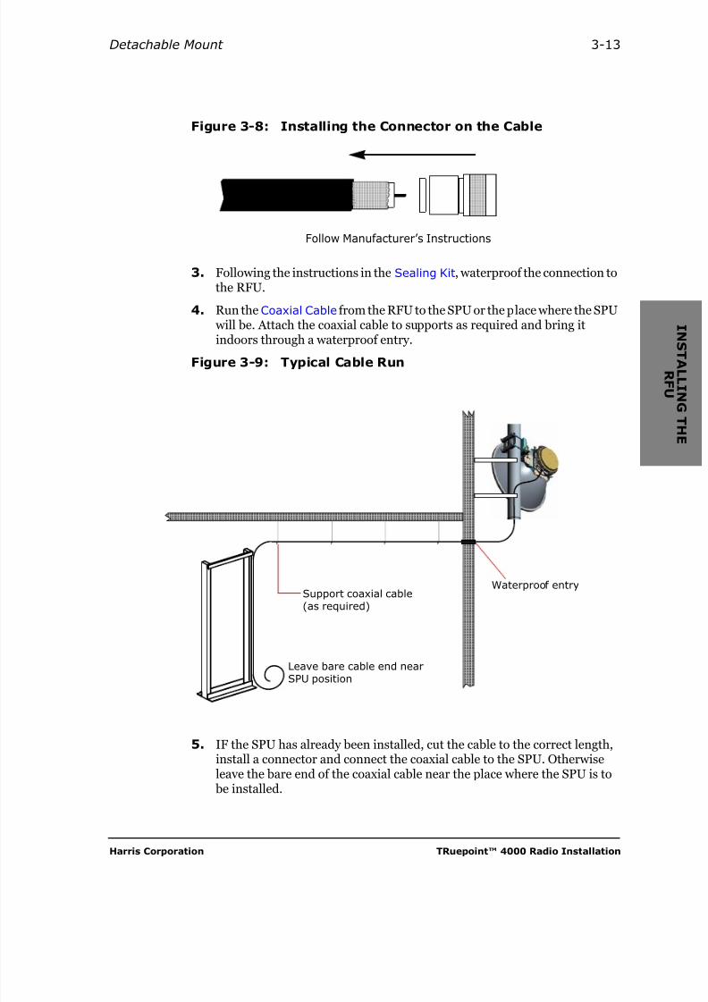
Figure 3-8: Installing the Connector on the Cable
3. Following the instructions in the Sealing Kit, waterproof the connection tothe RFU.
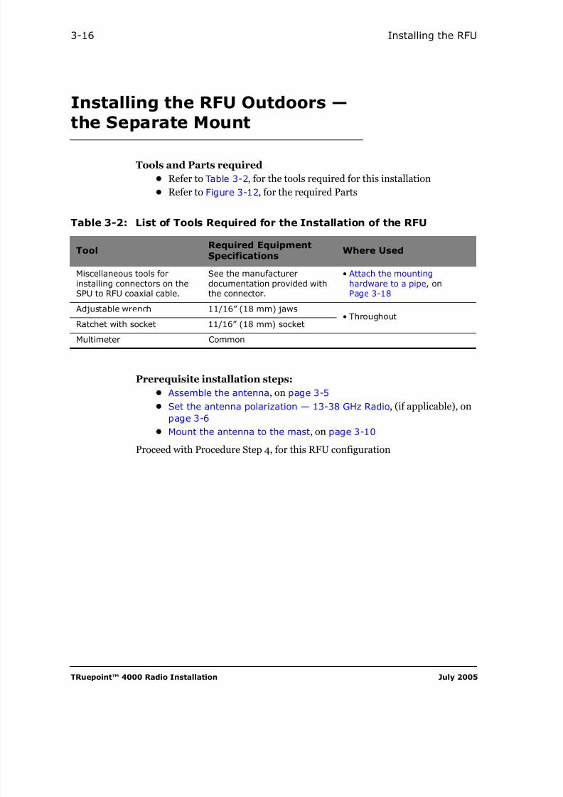
4. Run the Coaxial Cable from the RFU to the SPU or the place where the SPU will be. Attach the coaxial cable to supports as required and bring itindoors through a waterproof entry.
Figure 3-9: Typical Cable Run
5. IF the SPU has already been installed, cut the cable to the correct length,install a connector and connect the coaxial cable to the SPU. Otherwiseleave the bare end of the coaxial cable near the place where the SPU is to
be installed.
Follow Manufacturer’s Instructions
Leave bare cable end nearSPU position
Support coaxial cable(as required)
Waterproof entry

8/10/2019 Hariis TRuepoint 4000 - The Radio Installation
http://slidepdf.com/reader/full/hariis-truepoint-4000-the-radio-installation 40/118
TRuepoint™ 4000 Radio Installation July 2005
3-14 Installing the RFU
7 Ground the RFU and the Coaxial Cable
Tools and material required
• Common tools
• Three or more grounding kits (part # 099-099500-002)
1. Ground the RFU.
2. Following the instructions in the grounding kits, ground the coaxial cableat the RFU, the SPU and on the antenna side of any right angle turns.
Figure 3-10: Grounding the RFU and Coaxial Cable
Multistrand Copper Cable10 mm2 (8AWG)
Common Grounding Point
Coaxialgrounding kit
CoaxialGrounding Kits
RFUgrounding point
Coaxial Cable

8/10/2019 Hariis TRuepoint 4000 - The Radio Installation
http://slidepdf.com/reader/full/hariis-truepoint-4000-the-radio-installation 41/118
Harris Corporation TRuepoint™ 4000 Radio Installation
Detachable Mount 3-15
Grounding Requirements:For a roof-top installation, connect to the buildingground, or the water supply pipe where it enters thebuilding.For a tower installation connect to a good ring groundsystem made from buried copper cables and rods.Do NOT connect to the electrical utility ground.
Figure 3-11: RFU Grounding Detail
Remove Hex nut,install copper cable Grounding lug,and secure with Hex nut
Grounding lug
RSSI port
Coaxial cable port
Grounding stud withHex nut
8/10/2019 Hariis TRuepoint 4000 - The Radio Installation
http://slidepdf.com/reader/full/hariis-truepoint-4000-the-radio-installation 42/118
TRuepoint™ 4000 Radio Installation July 2005
3-16 Installing the RFU
Installing the RFU Outdoors —the Separate Mount
Tools and Parts required
• Refer to Table 3-2, for the tools required for this installation
• Refer to Figure 3-12, for the required Parts
Prerequisite installation steps:
• Assemble the antenna, on page 3-5
• Set the antenna polarization — 13-38 GHz Radio, (if applicable), on
page 3-6• Mount the antenna to the mast, on page 3-10
Proceed with Procedure Step 4, for this RFU configuration
Table 3-2: List of Tools Required for the Installation of the RFU
Tool Required EquipmentSpecifications Where Used
Miscellaneous tools forinstalling connectors on theSPU to RFU coaxial cable.
See the manufacturerdocumentation provided withthe connector.
• Attach the mountinghardware to a pipe, onPage 3-18
Adjustable wrench 11/16” (18 mm) jaws• Throughout
Ratchet with socket 11/16” (18 mm) socket
Multimeter Common
8/10/2019 Hariis TRuepoint 4000 - The Radio Installation
http://slidepdf.com/reader/full/hariis-truepoint-4000-the-radio-installation 43/118

8/10/2019 Hariis TRuepoint 4000 - The Radio Installation
http://slidepdf.com/reader/full/hariis-truepoint-4000-the-radio-installation 44/118
TRuepoint™ 4000 Radio Installation July 2005
3-18 Installing the RFU
4 Attach the mounting hardware to a pipe
Tools and material required
• An open-end 0.5” (13 mm) wrench
When selecting the position for the mounting hardware,remember that it must be connected to the antenna bythe available waveguide.
1. Loosen the nuts on the rods to widen the opening between the 2 halves
(Assembly’s jaws) of the mounting plate assembly, and slide the assemblyover the top of a pipe, if possible.
2. If you do not have access to the pipe’s top, unscrew and remove the nutsand washers from the rods on one half of the assembly, separate theAssembly’s jaws, then mount the jaws on the pipe while aligning the rodsthrough the corresponding holes on the other half of the assembly.
3. Ensure that the assembly is level, then secure the assembly to the pipe bytightening the nuts and washers on the rods, as shown in Figure 3-13.
Figure 3-13: Installing the RFU-Mounting Plate Assembly
22 N • m (16.2 lbf- ft.)
0.5” (13 mm)
Rods (4)
Wrench
Mounting Plate Assembly
Assembly’s jaws

8/10/2019 Hariis TRuepoint 4000 - The Radio Installation
http://slidepdf.com/reader/full/hariis-truepoint-4000-the-radio-installation 45/118
Harris Corporation TRuepoint™ 4000 Radio Installation
The Separate Mount 3-19
5 Mount the RFU on the mounting hardware
Tools and material required
• Adjustable wrench
1. Making sure to leave the O-ring in place, remove the protective tape fromthe waveguide ports on the RFU and the RFU-Mounting Plate.
2. Apply silicone grease, observing the Caution given in Figure 3-14.
3. Place the RFU against the RFU-mounting plate so that the cylindrical feedfits into a corresponding cavity on the RFU.
4. Place the locking latches over the corresponding mating hooks, then Closelatches so that the RFU is locked to the RFU-Mounting Plate.
Figure 3-14: Attaching the RFU to the Mounting Plate
R em o v e i n f o r m a t i o n t a g a n d c ap ,
t h e n a p p l y m o d e r a t e l y s i l i c o n e
g r e a se t o t h e w h o l e f ee d b o o m a r e a ,
b u t n o t t o i t s f a c e . Fa i l u r e t o d o s o ,
w i l l c au s e t h e RFU t o j a m .
Matinghooks (4)
Face View of Mounting Plate
RFU-Mounting Plate
Close latches
8/10/2019 Hariis TRuepoint 4000 - The Radio Installation
http://slidepdf.com/reader/full/hariis-truepoint-4000-the-radio-installation 46/118
TRuepoint™ 4000 Radio Installation July 2005
3-20 Installing the RFU
6 Connect the waveguide between the RFU and theantenna
Tools and material required
• Common tools
• Tools listed in the manufacturer’s instructions
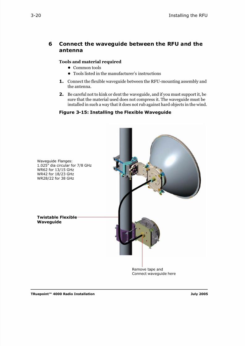
1. Connect the flexible waveguide between the RFU-mounting assembly andthe antenna.
2. Be careful not to kink or dent the waveguide, and if you must support it, besure that the material used does not compress it. The waveguide must beinstalled in such a way that it does not rub against hard objects in the wind.
Figure 3-15: Installing the Flexible Waveguide
Remove tape andConnect waveguide here
Twistable FlexibleWaveguide
Waveguide Flanges:1.025” dia circular for 7/8 GHzWR62 for 13/15 GHzWR42 for 18/23 GHz
WR28/22 for 38 GHz
8/10/2019 Hariis TRuepoint 4000 - The Radio Installation
http://slidepdf.com/reader/full/hariis-truepoint-4000-the-radio-installation 47/118
Harris Corporation TRuepoint™ 4000 Radio Installation
The Separate Mount 3-21
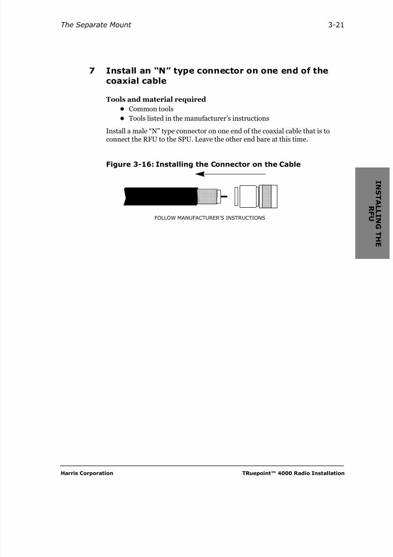
7 Install an “N” type connector on one end of thecoaxial cable
Tools and material required
• Common tools
• Tools listed in the manufacturer’s instructions
Install a male “N” type connector on one end of the coaxial cable that is toconnect the RFU to the SPU. Leave the other end bare at this time.
Figure 3-16: Installing the Connector on the Cable
FOLLOW MANUFACTURER’S INSTRUCTIONS
8/10/2019 Hariis TRuepoint 4000 - The Radio Installation
http://slidepdf.com/reader/full/hariis-truepoint-4000-the-radio-installation 48/118
TRuepoint™ 4000 Radio Installation July 2005
3-22 Installing the RFU
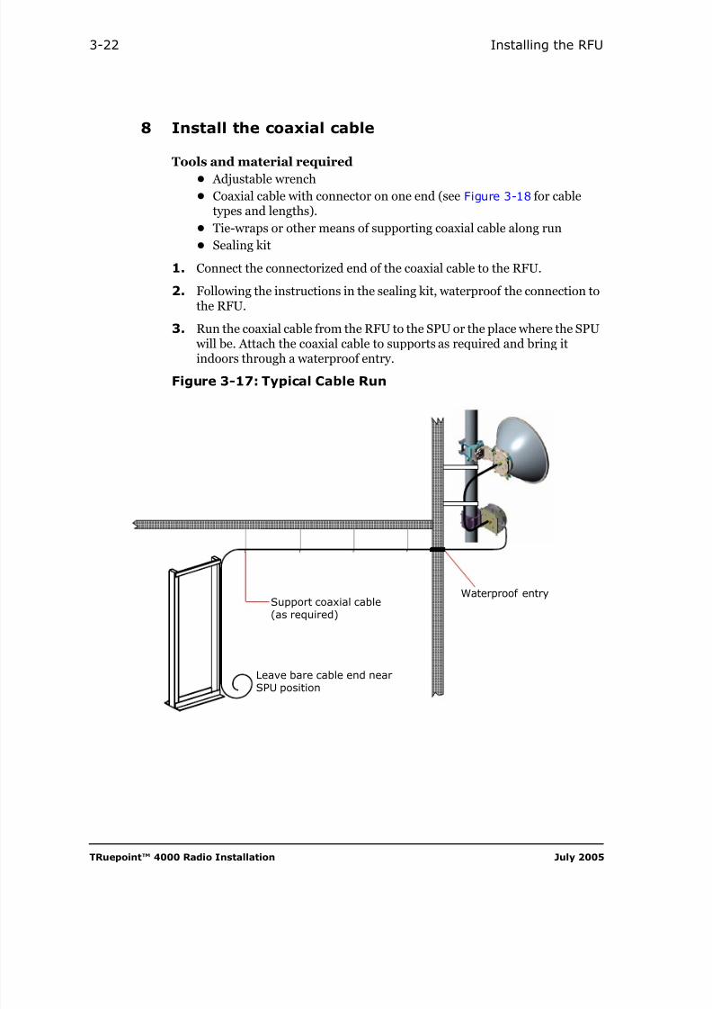
8 Install the coaxial cable
Tools and material required
• Adjustable wrench
• Coaxial cable with connector on one end (see Figure 3-18 for cabletypes and lengths).
• Tie-wraps or other means of supporting coaxial cable along run
• Sealing kit
1. Connect the connectorized end of the coaxial cable to the RFU.
2. Following the instructions in the sealing kit, waterproof the connection tothe RFU.
3. Run the coaxial cable from the RFU to the SPU or the place where the SPU
will be. Attach the coaxial cable to supports as required and bring itindoors through a waterproof entry.
Figure 3-17: Typical Cable Run
Leave bare cable end nearSPU position
Support coaxial cable(as required)
Waterproof entry

8/10/2019 Hariis TRuepoint 4000 - The Radio Installation
http://slidepdf.com/reader/full/hariis-truepoint-4000-the-radio-installation 49/118
Harris Corporation TRuepoint™ 4000 Radio Installation
The Separate Mount 3-23
Figure 3-18: Connecting The Coaxial Cable to the RFU
Coaxial Cable Type
Part Number Description Comments
087-099499-XX0Foam core 50 Ω heliax shielded cable(Andrews LDF2-50)
Cable only, XX0 =210 m to 300 m in10 m increments
099-901208-001
Low loss50 Ω RG 8/U kit
45 m Kit contains low lossRG 8/U cable,sealing kit, 2 N-typeconnectors, and3 grounding kits.
099-901208-002 90 m
099-901208-003 150 m
099-901208-004 210 m
Connect here andinstall Sealing Kit

8/10/2019 Hariis TRuepoint 4000 - The Radio Installation
http://slidepdf.com/reader/full/hariis-truepoint-4000-the-radio-installation 50/118
TRuepoint™ 4000 Radio Installation July 2005
3-24 Installing the RFU
9 Ground the RFU and the coaxial cable
Tools and material required
• Common tools
• Three or more grounding kits
1. Ground the RFU.
2. Following the instructions in the grounding kits, ground the coaxial cableat the RFU, the SPU and on the antenna side of any right angle turns.
Grounding Requirements:
For a roof-top installation, connect to the buildingground, or the water supply pipe where it enters thebuilding.For a tower installation connect to a good ring groundsystem made from buried copper cables and rods.Do NOT connect to the electrical utility ground.

8/10/2019 Hariis TRuepoint 4000 - The Radio Installation
http://slidepdf.com/reader/full/hariis-truepoint-4000-the-radio-installation 51/118
Harris Corporation TRuepoint™ 4000 Radio Installation
The Separate Mount 3-25
Figure 3-19: Grounding the RFU and Coaxial Cable
Multistrand Copper Cable10 mm2 (8AWG)
Common Grounding Point
CoaxialGrounding Kits
Coaxial Cable
Refer to RFUGrounding Detail,on page 3-15
Refer to
Installing the Flexible Waveguide,on page 3-20

8/10/2019 Hariis TRuepoint 4000 - The Radio Installation
http://slidepdf.com/reader/full/hariis-truepoint-4000-the-radio-installation 52/118
TRuepoint™ 4000 Radio Installation July 2005
3-26 Installing the RFU

8/10/2019 Hariis TRuepoint 4000 - The Radio Installation
http://slidepdf.com/reader/full/hariis-truepoint-4000-the-radio-installation 53/118
Harris Corporation TRuepoint™ 4000 Radio Installation
4-1
C H A P T E R
4INSTALLING THE SPU
General
You would normally reach this point a f t e r you have completedInstalling the RFU.
Before installing the SPU, ensure preparing a clean, secure room for it, andprovide the following:
• a coaxial cable, from the RFU;
• a 21-60 VDC power source1; and
• access to the building ground terminal.
Although the installation of the SPU does not requireadvanced technical skills, we strongly recommend thatthe technical personnel possesses the knowledge andskills appropriate for making such installations.Power connections to the microwave radio must bemade in compliance with local electrical codes by aSkilled Person. Harris Corporation disclaims any liabilityor responsibility for the results of improper or unsafeinstallation practices.
1. Power source recommended to follow ETSI EN 300 132-2 guidelines and Telcordia objective GR-499.

8/10/2019 Hariis TRuepoint 4000 - The Radio Installation
http://slidepdf.com/reader/full/hariis-truepoint-4000-the-radio-installation 54/118
TRuepoint™ 4000 Radio Installation July 2005
4-2 Installing the SPU
X
Figure 4-1: Parts for SPU Installation, as a Minimum
In order to easily replace the SPU, ensure that all cablesare routed from the rack sides and at the level of their
respective connectors. Doing so, allows you to replace aunit with the least operation disruption.
Table 4-1: Tools required
Tool
Required equipment
specifications Where used
Screwdriver Phillips #2 General
Multimeter With ohm meter
• Connect the Coaxial Cablesto the SPU, on page 4-5
Miscellaneous tools forinstalling connectors on theSPU to RFU coaxial cable.
Refer to the manufacturerdocumentation provided withthe connector.
Tie-Wraps or Cable
Clamps to supportCables
Grounding Lug
MountingBrackets (2)

8/10/2019 Hariis TRuepoint 4000 - The Radio Installation
http://slidepdf.com/reader/full/hariis-truepoint-4000-the-radio-installation 55/118
Harris Corporation TRuepoint™ 4000 Radio Installation
Hardware Installation 4-3
Procedure
1 Install the SPU in the rack
Tools and material required
• A number-2 cross-head screw driver
Secure the SPU to the rack using the screws provided, in the position shown inFigure 4-2. The position will depend on your situation and what otherequipment you have or plan to have in the rack.
Figure 4-2: SPU Stacking Configurations — Still Air Conditions
0
5
10
15
20
0
5
10
15
20
1-RMS SPU1-RMS SPU
1-RMS SPU1-RMS SPU
1-RMS SPU1-RMS SPU
0
5
10
15
20
0
5
10
15
201-RMS SPU
1-RMS SPU
1-RMS SPU
1-RMSfreespace

8/10/2019 Hariis TRuepoint 4000 - The Radio Installation
http://slidepdf.com/reader/full/hariis-truepoint-4000-the-radio-installation 56/118
TRuepoint™ 4000 Radio Installation July 2005
4-4 Installing the SPU
Figure 4-3: Other Allowable Stacking Configurations —Cross Airflow Velocity Conditions of 0.625 m/s
0
5
10
15
20
0
5
10
15
201-RMS SPU
1-RMS SPU
0
5
10
15
20
0
5
10
15
20
1-RMS SPU1-RMS SPU
1-RMS SPU1-RMS SPU
1-RMS SPU1-RMS SPU
1-RMSfreespace
1-RMS SPU1-RMS SPU
1-RMS SPU1-RMS SPU
(Typ.)

8/10/2019 Hariis TRuepoint 4000 - The Radio Installation
http://slidepdf.com/reader/full/hariis-truepoint-4000-the-radio-installation 57/118
Harris Corporation TRuepoint™ 4000 Radio Installation
Hardware Installation 4-5
2 Connect the Coaxial Cables to the SPU
Tools and material required
• Common tools
• A multimeter
• An N-type connector compatible with the type of coaxial cable that youare using.
If the RFU has already been installed you should find theend of the interconnect cable near the SPU.
1. Cut the cable to a length which will leave about 6 inches (15 cm) of slackafter it has been connected to the SPU.
2. Following the instructions that come with the connector, install an N-typeconnector on each cable.
3. Using the multimeter, check that the resistance between the coaxial cable’scenter connector and the shield is more than 100 Ω, with the far endconnected to the RFU.
A l o w e r r e s i s t a n c e v a l u e i n d i ca t e s t h a t t h e r e i s a
s h o r t i n t h e c o a x i a l c a b le o r i n t h e R FU t h a t m a y
d a m a g e t h e SP U’ s p o w e r sw i t ch ( b r e a k e r ) w h e n i t
i s s w i t c h e d ON . I f t h i s i s t h e c a s e, r ep l a c e t h e
f a u l t y e l e m e n t ( c a b le o r R FU ) .
4. Connect the cables to the RFU Cable ports on the Modem(s).(Cable types and lengths are given in Table 4-2).
5. Support the cable if necessary.

8/10/2019 Hariis TRuepoint 4000 - The Radio Installation
http://slidepdf.com/reader/full/hariis-truepoint-4000-the-radio-installation 58/118
TRuepoint™ 4000 Radio Installation July 2005
4-6 Installing the SPU
Figure 4-4: Connecting the Coaxial Cable to the SPU
Re s is t a n c e b e t w e e n t h e co a x i a l c a b l e ’ s
c e n t e r co n n e c t o r a n d t h e s h i e ld m u s t b e
m o r e t h a n 1 0 0 Ω
Table 4-2: Coaxial Cable Types and Lengthsa
a. Refer to Chapter 6 for more coaxial cable options
Part Number Description Comments
087-099499-XX0Foam core 50 Ω heliaxshielded cable(Andrews LDF2-50)
Cable only, XX0 = 210 mto 300 m in 10 mincrements
099-901208-001
Low loss50 Ω RG 8/U kit
45 mKit contains low lossRG 8/U cable, sealing kit,2 N-type connectors, and3 grounding kits.
099-901208-002 90 m
099-901208-003 150 m
099-901208-004 210 m

8/10/2019 Hariis TRuepoint 4000 - The Radio Installation
http://slidepdf.com/reader/full/hariis-truepoint-4000-the-radio-installation 59/118
Harris Corporation TRuepoint™ 4000 Radio Installation
Hardware Installation 4-7
3 Ground the SPU
Tools and material required
• A number-2 cross-head screw driver
Ground the SPU by connecting 3.26 mm (8 AWG) copper cable from thegrounding point lug on the left side of the SPU enclosure to the radio system’smain grounding point.
For a roof-top installation, the main grounding point could be the buildingground, or the water supply pipe just before it enters the building.
For a tower installation, it should be a good ring ground system made from buried copper cables and rods. DO NOT connect to the electrical utilityground.
Safety Requirements for Grounding1. It is very important that the path of lowest impedance go directly to the
main grounding point.
2. Do not connect other equipment to the same grounding cable as the SPU.Each piece of equipment at the site should have a separate grounding cableto a common very low impedance main grounding point.
3. Locate this equipment in the same immediate area (adjacent cabinets) asany other equipment that has a connection between the groundedconductor of the same d.c. supply circuit and the grounding conductor,and also the point of grounding of the d.c. system. DO NOT ground the
d.c. system elsewhere.
4. Connect this equipment directly to the d.c. supply system groundingelectrode conductor or to a bonding jumper from a grounding terminal
bar, or bus to which the d.c. supply grounding electrode is connected.
5. Locate the d.c. supply source within the same premises as the equipment.
6. There shall be no switching or disconnecting devices in the groundedcircuit conductor between the d.c. source and the point of connection ofthe grounding electrode conductor.
Co n n e c t p o w e r c a b l e e n d t o H a r r i s ’ o p t i o n a l fu s e
p a n e l , o r p r o v i d e f u s i n g a c c o r d i n g t o L o ca l a n d
N a t i o n a l El e c t r i c a l Co d e s . Fu s e r a t i n g s m u s t b e :
4 A f o r 4 8 V , a n d 7 .5 t o 8 A f o r 2 4 V o p e r a t i o n s .
8/10/2019 Hariis TRuepoint 4000 - The Radio Installation
http://slidepdf.com/reader/full/hariis-truepoint-4000-the-radio-installation 60/118
TRuepoint™ 4000 Radio Installation July 2005
4-8 Installing the SPU
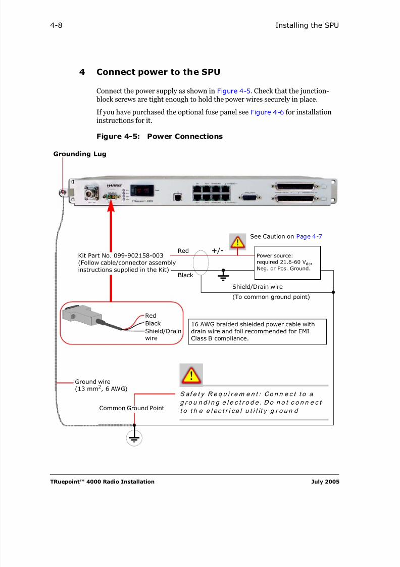
4 Connect power to the SPU
Connect the power supply as shown in Figure 4-5. Check that the junction-
block screws are tight enough to hold the power wires securely in place.
If you have purchased the optional fuse panel see Figure 4-6 for installationinstructions for it.
Figure 4-5: Power Connections
S af e t y R e q u i r e m e n t : Co n n e c t t o ag r o u n d i n g e l e c t r o d e . D o n o t c o n n e c t
t o t h e e l ec t r i ca l u t i l i t y g r o u n d
Ground wire(13 mm2, 6 AWG)
Common Ground Point
Grounding Lug
Kit Part No. 099-902158-003(Follow cable/connector assemblyinstructions supplied in the Kit)
+/-
Shield/Drain wire
Red
Black
(To common ground point)
16 AWG braided shielded power cable withdrain wire and foil recommended for EMIClass B compliance.
See Caution on Page 4-7
Power source:required 21.6-60 Vdc,
Neg. or Pos. Ground.
RedBlackShield/Drainwire

8/10/2019 Hariis TRuepoint 4000 - The Radio Installation
http://slidepdf.com/reader/full/hariis-truepoint-4000-the-radio-installation 61/118
Harris Corporation TRuepoint™ 4000 Radio Installation
Hardware Installation 4-9
Figure 4-6: Optional Fuse Panel — Back View Wiring
From Modem +/- terminal
Drain wire from power cable (Modem) connected tofuse panel grounding lug
Fuse panel grounding wire
From Modem Battery
From Modem
If required, connect alarmequipment to alarm relays here
To Alarms
To Modem
To CommonGround Point
Check that wire is on
Use small screwdriver
Connect the terminallabelled BATT to the batteryterminal that is not grounded
Connect the terminallabelled RTN to the batteryterminal that is grounded
this side of clamp
Turn clockwise to tighten
Install junction coverswhen finished
terminal

8/10/2019 Hariis TRuepoint 4000 - The Radio Installation
http://slidepdf.com/reader/full/hariis-truepoint-4000-the-radio-installation 62/118
TRuepoint™ 4000 Radio Installation July 2005
4-10 Installing the SPU
Figure 4-7: Optional Fuse Panel — Front View
Stick peg holders on panel above fuseslots. Insert colored pegs to indicatevalue of corresponding fuses
Stick fuse usage labels to panelInsert GMT-type fuses,(fuse ratings per Note provided below).Keep fuse blanks in unused positions.
GMT-type fuse rating: 4 A for 48 V operation,
and 7.5 A for 24 V operation.

8/10/2019 Hariis TRuepoint 4000 - The Radio Installation
http://slidepdf.com/reader/full/hariis-truepoint-4000-the-radio-installation 63/118
Harris Corporation TRuepoint™ 4000 Radio Installation
Hardware Installation 4-11
5 Connect the MUX Tributaries
Tools and material required
Cables with connectors appropriate to the Multiplexer options ordered.
If equipped, connect appropriate cables to both theSCSI-1 and RJ-45 ports for the mixed traffic option, upto 16 E1 + packet data.
Figure 4-8: Connecting Tributaries and Mixed Traffic —Cables with SCSI-1 Connectors and RJ-45
Ev e r y S PU s h i p s w i t h E SD c a p s , o n e i n s t a l l e d o ne a ch u n u s e d “ T r ib u t a r i e s” p o r t . A l w a y s r e m em b e r
t o k e e p a n y u n u s e d p o r t c o v er e d w i t h s u ch c a p .
T h i s i s an E SD p r o t e c t i o n r e q u i r e m e n t . Y o u n e e d
t o k e e p t h e r e m o v e d c ap f o r f u t u r e u s e .
Connect tributaries
10/100BASE-T 1
10/100BASE-T 2

8/10/2019 Hariis TRuepoint 4000 - The Radio Installation
http://slidepdf.com/reader/full/hariis-truepoint-4000-the-radio-installation 64/118
TRuepoint™ 4000 Radio Installation July 2005
4-12 Installing the SPU
Figure 4-9: Tributary Connection Example —Using the BNC Interconnect Panel
Connect the Amphenol Connector from the BNC panel to the TRI B U T AR I E S ( 1 - 8 ) and TRI B U T AR I E S ( 9 - 1 6 ) ports, on the SPU, where applicable. And, using 75 Ω coaxial cable with male BNC connectors at the SPU-end and the chosen connectors atthe other, connect the tributary inputs and outputs on the panel to your equipment.The inputs and outputs are labelled on the panel, E1 (IN) through E8 (OUT).
P/N 101-901415-002 forUnbalanced Operation Only(2 BNC panels required for 16 E1)
E1 (IN)
E1 (OUT)
E8 (OUT)
E8 (IN)
Amphenol Connector(to the TR I BUTAR I ES ports)

8/10/2019 Hariis TRuepoint 4000 - The Radio Installation
http://slidepdf.com/reader/full/hariis-truepoint-4000-the-radio-installation 65/118
Harris Corporation TRuepoint™ 4000 Radio Installation
Hardware Installation 4-13
Figure 4-10: Tributary Connection Example —Using the 50-Pin Amphenol to BNC CableAssembly
Connect the Amphenol Connector on the assembly to the TRI B U T AR I E S ( 1 - 8 )
and TRI B U TA R I E S ( 9 - 1 6 ) ports, on the SPU, where applicable. And, using 75 Ω coaxial cable with male BNC connectors at the SPU-end and the chosen connectorsat the other, connect the tributary inputs and outputs on the assembly to yourequipment. The inputs and outputs are labelled on the female BNC connectors.
Female to Male BNC Connection(Unbalanced Operation)
50-Pin Amphenol to BNC Cable Assembly
Part Number Length, ft. (m) Capacity
087-901346-002 1.5 (0.4575) 8 E1, Unbalanced
087-901346-004 9 (2.75) 8 E1, Unbalanced
For Unbalanced Operation Only
BNC male connectorsfrom User’s DistributionFrame connect here.2 BNC connectors pertributary
8 E1 Option shown
Amphenol Connector
(to the TR I BUTAR I E S ports)

8/10/2019 Hariis TRuepoint 4000 - The Radio Installation
http://slidepdf.com/reader/full/hariis-truepoint-4000-the-radio-installation 66/118
TRuepoint™ 4000 Radio Installation July 2005
4-14 Installing the SPU
Figure 4-11: Tributary Connection Example —Using the Connectorized Cable
Connect the Amphenol connectors to the TRI B U T AR I E S ( 1 - 8 ) andTR I B U T A RI ES ( 9 - 1 6 ) ports on the balanced SPU. At the other end, install yourown connector or wire-wrap the bare wires to your equipment. A label at theuser’s end of the cable indicates which tributaries the bare wires connect to.For the cable lengths, see table below
Connectorized Cable Assembly, Shielded
Part Number Length, ft. (m) Capacity
098-901250-001 32.5 (9.91)
2/4/8/16 E1,Balanced
098-901250-002 10 (3.05)
098-901250-003 20 (6.1)
098-901250-004 100 (30.5)
This connector connects to SPU’s PortTRIBUTARIES (1-8) or (9-16)
End of this cable connects toUser’s Distribution Frame

8/10/2019 Hariis TRuepoint 4000 - The Radio Installation
http://slidepdf.com/reader/full/hariis-truepoint-4000-the-radio-installation 67/118

8/10/2019 Hariis TRuepoint 4000 - The Radio Installation
http://slidepdf.com/reader/full/hariis-truepoint-4000-the-radio-installation 68/118
TRuepoint™ 4000 Radio Installation July 2005
4-16 Installing the SPU
7 Connect other SPUs in repeater or spurconfiguration
Tools and material required
• Common tools
• Network cables, straight type RJ45, 10BASE-T compliant, length asrequired:
- 1 for repeater
- 2 for repeater with spur.
The NTWRK/LAN 1-2 connections provide protectionfor the auxiliary channels, as well as network data andcustomer data on SPUs.
Figure 4-13: Repeater Connections
To other Repeaters
RJ-45 Cable P/N 087-020193-7xx(Refer to Table 6-1 for details)
8/10/2019 Hariis TRuepoint 4000 - The Radio Installation
http://slidepdf.com/reader/full/hariis-truepoint-4000-the-radio-installation 69/118
Harris Corporation TRuepoint™ 4000 Radio Installation
Hardware Installation 4-17
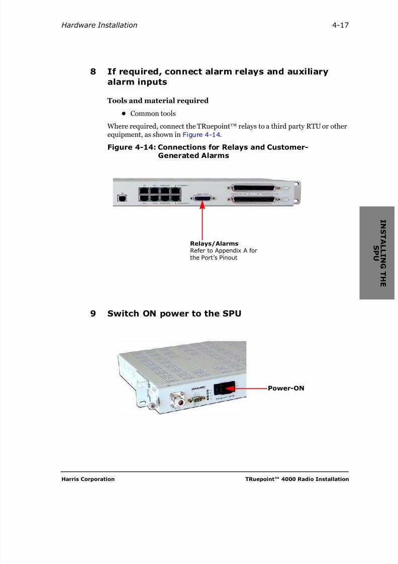
8 If required, connect alarm relays and auxiliaryalarm inputs
Tools and material required
• Common tools
Where required, connect the TRuepoint™ relays to a third party RTU or otherequipment, as shown in Figure 4-14.
Figure 4-14: Connections for Relays and Customer-Generated Alarms
9 Switch ON power to the SPU
Relays/AlarmsRefer to Appendix A forthe Port’s Pinout
Power-ON
8/10/2019 Hariis TRuepoint 4000 - The Radio Installation
http://slidepdf.com/reader/full/hariis-truepoint-4000-the-radio-installation 70/118
TRuepoint™ 4000 Radio Installation July 2005
4-18 Installing the SPU
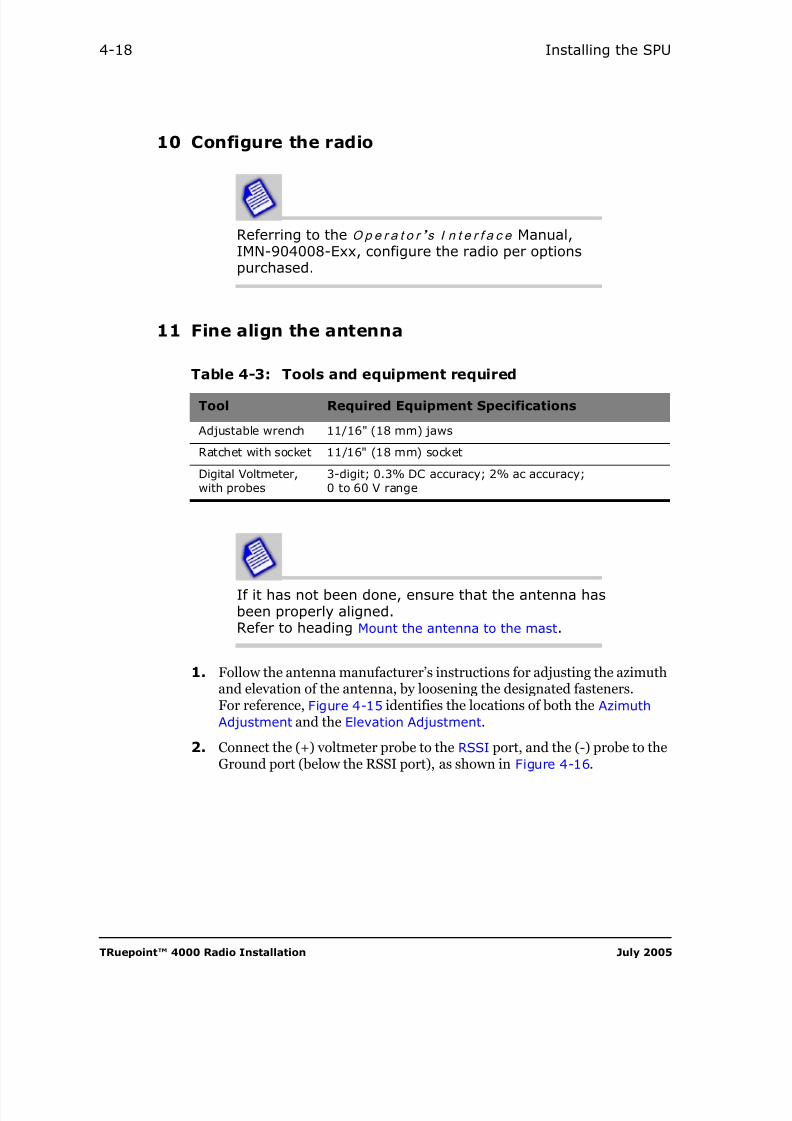
10 Configure the radio
Referring to the O p e r a t o r ’ s I n t e r f a c e Manual,IMN-904008-Exx, configure the radio per optionspurchased.
11 Fine align the antenna
If it has not been done, ensure that the antenna hasbeen properly aligned.Refer to heading Mount the antenna to the mast.
1. Follow the antenna manufacturer’s instructions for adjusting the azimuthand elevation of the antenna, by loosening the designated fasteners.For reference, Figure 4-15 identifies the locations of both the AzimuthAdjustment and the Elevation Adjustment.
2. Connect the (+) voltmeter probe to the RSSI port, and the (-) probe to theGround port (below the RSSI port), as shown in Figure 4-16.
Table 4-3: Tools and equipment required
Tool Required Equipment Specifications
Adjustable wrench 11/16" (18 mm) jaws
Ratchet with socket 11/16" (18 mm) socket
Digital Voltmeter,with probes
3-digit; 0.3% DC accuracy; 2% ac accuracy;0 to 60 V range

8/10/2019 Hariis TRuepoint 4000 - The Radio Installation
http://slidepdf.com/reader/full/hariis-truepoint-4000-the-radio-installation 71/118
Harris Corporation TRuepoint™ 4000 Radio Installation
Configuration 4-19
Figure 4-15: Locating the Azimuth and Elevation Adjustments
3. Adjust the direction of the antenna until you have a m a x i m u m RSL voltage1 at the RSSI test points, as shown in Figure 4-16.
Figure 4-16: Measuring the RSL Voltage through the digitalvoltmeter
Azimuth Adjustment
Elevation Adjustment
Detachable configuration shown
1. Voltage value d i r e c t l y proportional to RSL, when the proportional option is selected during the SPUconfiguration, before the alignment
V
V
VOLTMETER
+ –
Angle
V Maximum peak resultingfrom antenna alignmentto the main lobes
Secondaryvoltage peaksfrom side-lobes
Right
Main lobes aligned
RSSI

8/10/2019 Hariis TRuepoint 4000 - The Radio Installation
http://slidepdf.com/reader/full/hariis-truepoint-4000-the-radio-installation 72/118
TRuepoint™ 4000 Radio Installation July 2005
4-20 Installing the SPU
4. When finished, tighten ALL fasteners loosened previously to 22 N•m(16.2 lbf-ft.)
RSSI Voltage/RSLDepending on the scale configuration, the RSL voltage reading is eitherd i r e c t l y or i n v e r se l y proportional to the RSL.
Step 3 above, uses the default d i r e c t l y proportional scale configuration, alsoknown as the Uncalibrated RSSI,
Menu path: CONFIGURATION > SYSTEM > RFU > RSSI OUT> PROPORTIONAL
The i n v e r se l y proportional scale uses a multiplication factor of –20.That is, an amplitude of 3 V dc translates into an RSL of –60 dBm.
Menu path: CONFIGURATION > SYSTEM > RFU > RSSI OUT> INVERTED
Table 4-4: RSL Voltage to RSL Relationship
RSL Voltage,(Vdc)
Corresponding RSLa,(dBm), inverse scale
a. I n v e r s e l y proportional scale configuration using a conversion factor of -20
Uncalibrated RSSIb,direct scale
b. D i r ect ly proportional scale configuration
.5 >-20c
c. As displayed on the Hand-held terminal — out of range
Uncalibrated raw RSSI voltage
.75 >-20
1.0 -20
1.5 -30
2.0 -40
2.5 -50
3.0 -60
3.5 -70
4.75 -95
5 <-95c

8/10/2019 Hariis TRuepoint 4000 - The Radio Installation
http://slidepdf.com/reader/full/hariis-truepoint-4000-the-radio-installation 73/118

8/10/2019 Hariis TRuepoint 4000 - The Radio Installation
http://slidepdf.com/reader/full/hariis-truepoint-4000-the-radio-installation 74/118
TRuepoint™ 4000 Radio Installation July 2005
4-22 Installing the SPU

8/10/2019 Hariis TRuepoint 4000 - The Radio Installation
http://slidepdf.com/reader/full/hariis-truepoint-4000-the-radio-installation 75/118
Harris Corporation TRuepoint™ 4000 Radio Installation
C H A P T E R
5MAINTENANCE
Maintenance
There is no routine maintenance required on the TRuepoint™ radio. If a radiodoes fail, it is repaired by replacing faulty module(s) in the RFU. There are nofield adjustments to be made within the RFU.
Basic Troubleshooting
Table 5-1 identifies probable causes of typical problems through the Modem’sLEDs. For more advanced troubleshooting, refer to the Ope r a t o r ’ s
I n t e r f a c e manual, IMN-90408-Exx.

8/10/2019 Hariis TRuepoint 4000 - The Radio Installation
http://slidepdf.com/reader/full/hariis-truepoint-4000-the-radio-installation 76/118
TRuepoint™ 4000 Radio Installation July 2005
5-2 Maintenance
Figure 5-1: SPU’s LEDs
Table 5-1: Indicator Light Display Description
Label Color Description
SPUGreen SPU is on-line and functioning normally
Red The SPU has failed
RFUGreen The RFU is operating properly
Red The RFU has failed
CableGreen The SPU-RFU cable is working properly
Red The SPU-RFU cable has failed
SUMGreen The system (local and remote) is operating properly
Red Alarm present on system (local or remote)
SPU
RFU
Cable
SUM
LEDs
DC Power Input
RFU Cable
8/10/2019 Hariis TRuepoint 4000 - The Radio Installation
http://slidepdf.com/reader/full/hariis-truepoint-4000-the-radio-installation 77/118
Harris Corporation TRuepoint™ 4000 Radio Installation
5-3
Replacing Units
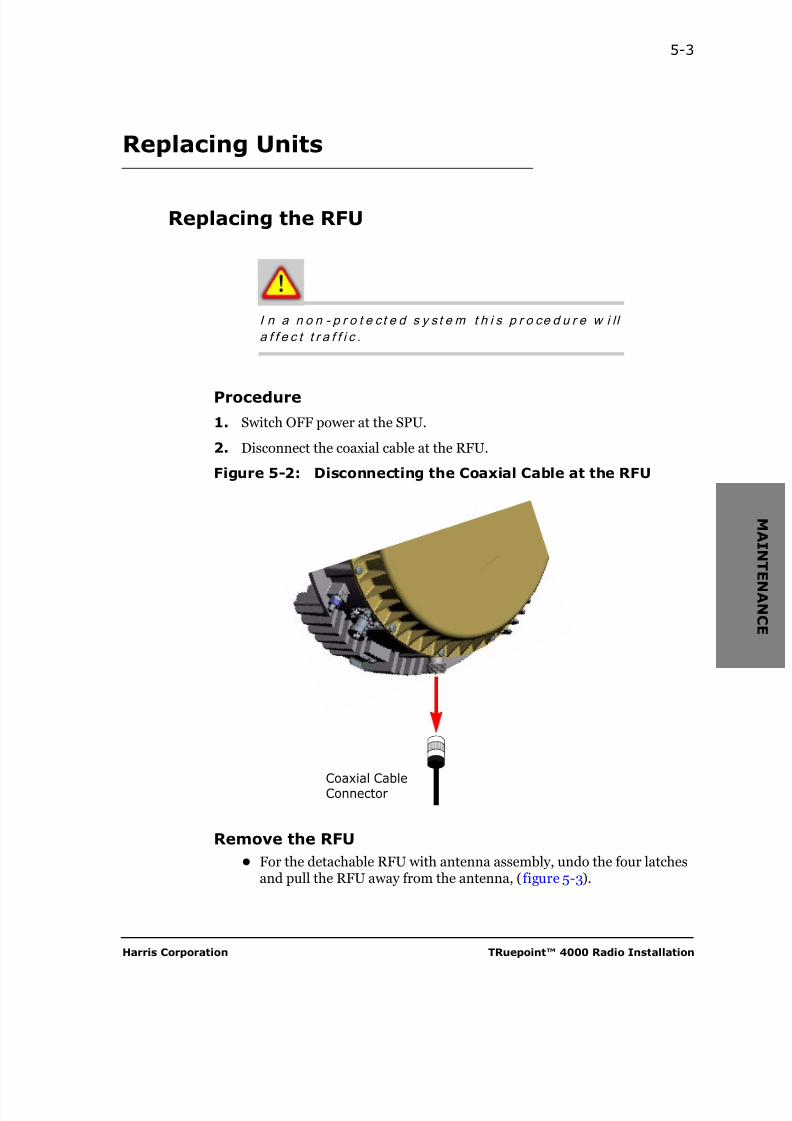
Replacing the RFU
I n a n o n - p r o t e c t e d s y s t e m t h i s p r o ce d u r e w i l l
a f f e c t t r a f f i c .
Procedure
1. Switch OFF power at the SPU.
2. Disconnect the coaxial cable at the RFU.
Figure 5-2: Disconnecting the Coaxial Cable at the RFU
Remove the RFU• For the detachable RFU with antenna assembly, undo the four latches
and pull the RFU away from the antenna, (figure 5-3).
Coaxial CableConnector
8/10/2019 Hariis TRuepoint 4000 - The Radio Installation
http://slidepdf.com/reader/full/hariis-truepoint-4000-the-radio-installation 78/118
TRuepoint™ 4000 Radio Installation July 2005
5-4 Maintenance
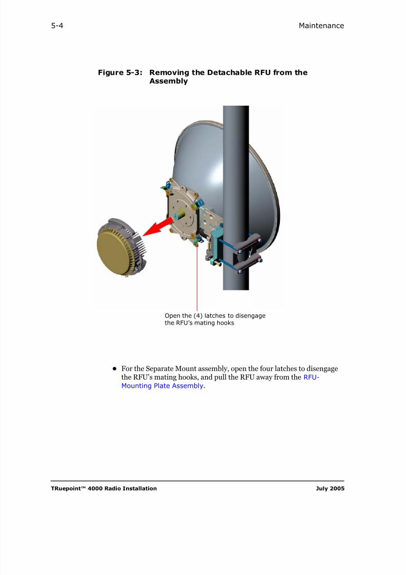
Figure 5-3: Removing the Detachable RFU from theAssembly
• For the Separate Mount assembly, open the four latches to disengagethe RFU’s mating hooks, and pull the RFU away from the RFU-Mounting Plate Assembly.
Open the (4) latches to disengagethe RFU’s mating hooks

8/10/2019 Hariis TRuepoint 4000 - The Radio Installation
http://slidepdf.com/reader/full/hariis-truepoint-4000-the-radio-installation 79/118
Harris Corporation TRuepoint™ 4000 Radio Installation
5-5
Figure 5-4: Removing the Detachable RFU from theMounting Plate Assembly
Install a new RFU
1. Apply silicone grease to the antenna cylinder, referring to the Caution, onpage 3-11.
2. Install the new RFU with the same part number by reversing theappropriate procedure referenced by Figures 3-6 and 3-14.
3. Reconnect the coaxial cable.
4. If outdoors, install a new sealing kit on the coaxial cable connector.
5. Reconfigure the system through the HHT, and referring to section Makingthe radio work.
Open the (4) latches
Mating hooks (4)
RFU-Mounting Plate Assembly

8/10/2019 Hariis TRuepoint 4000 - The Radio Installation
http://slidepdf.com/reader/full/hariis-truepoint-4000-the-radio-installation 80/118
TRuepoint™ 4000 Radio Installation July 2005
5-6 Maintenance
Replacing the SPU
Traffic is interrupted during this procedure. You maywant to move traffic to an alternate equipment beforestarting.
Procedure
1. Switch OFF power to the SPU at the source, (breaker).
2. Disconnect the power and ground wires from the SPU.
3. Disconnect the coaxial cable from the SPU.
4. Disconnect all other wires and cables from the SPU.
5. Replace the SPU with a new one that bears the sam e part number andincludes the same software version as the replaceable one.Refer to Chapter 4, Installing the SPU.
6. Install and reconnect all wires and cables to the SPU.
B e f o r e c o n n e c t i n g t h e c o a x i a l c a b l e t o t h e SPU ,
m a k e s u r e t o c h e ck f o r t h e p r e s e n ce o f a s h o r t
a l o n g t h e c a b l e le n g t h . A sh o r t i n t h i s ca b l e o r i n
t h e R FU m a y d am a g e t h e S PU ’ s b r e a k e r w h e n i t i s
s w i t c h e d ON . I f t h i s i s t h e c a se , r e p la c e t h e f a u l t y
e l em e n t ( c a b le o r R FU ) .
7. Switch ON power to the SPU at the source.
8. Use the embedded control software and user interface to configure theSPU. Refer to the Oper a t o r ’ s I n t e r f a c e manual, IMN-904008-Exx.

8/10/2019 Hariis TRuepoint 4000 - The Radio Installation
http://slidepdf.com/reader/full/hariis-truepoint-4000-the-radio-installation 81/118
Harris Corporation TRuepoint™ 4000 Radio Installation
C H A P T E R
6OPTIONS AND ORDERING
To maintain your microwave radio with a minimum of down time, yourorganization will have to maintain a stock of spare units (or modules). To doso, you may wish to order additional spares from time to time, to assure that
you have enough spares to properly maintain the system. In addition, after you replace a faulty unit with a spare, you will want to return the faulty unit toHarris for repair. This Chapter explains how to accomplish these tasks.
Ordering
Part Numbers Versus Product Codes
The best way to identify an item that you wish to order is to give us a partnumber. A part number identifies a specific part and is found on a label affixedto the part, as shown in Figure 6-1. On that label, there may also be a productcode, which is a more general number that identifies the most up to-date partthat serves a specific function. If possible, please provide the part number.
Spare Unit Ordering Information
When you order spare parts for your existing system, refer to the parts list inTable 6-1 and provide the Part Number.
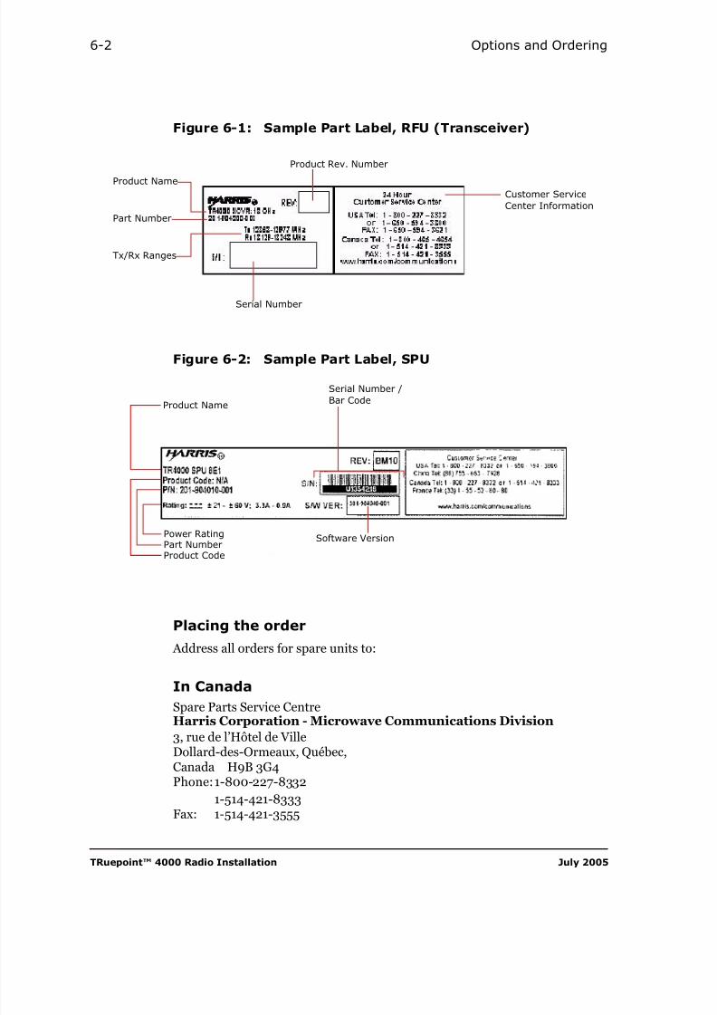
8/10/2019 Hariis TRuepoint 4000 - The Radio Installation
http://slidepdf.com/reader/full/hariis-truepoint-4000-the-radio-installation 82/118
TRuepoint™ 4000 Radio Installation July 2005
6-2 Options and Ordering
Figure 6-1: Sample Part Label, RFU (Transceiver)
Figure 6-2: Sample Part Label, SPU
Placing the order
Address all orders for spare units to:
In Canada
Spare Parts Service CentreHarris Corporation - Microwave Communications Division
3, rue de l’Hôtel de VilleDollard-des-Ormeaux, Québec,Canada H9B 3G4Phone:1-800-227-8332
1-514-421-8333Fax: 1-514-421-3555
Serial Number
Customer ServiceCenter Information
Product Name
Part Number
Tx/Rx Ranges
Product Rev. Number
Serial Number /Bar Code
Software Version
Product Name
Power RatingPart NumberProduct Code

8/10/2019 Hariis TRuepoint 4000 - The Radio Installation
http://slidepdf.com/reader/full/hariis-truepoint-4000-the-radio-installation 83/118
Harris Corporation TRuepoint™ 4000 Radio Installation
Ordering 6-3
Table 6-1: Common Parts for TRuepoint™ 4000
Part Number Description Comments
Radio Frequency Units
• 7 GHz RFU• -48VDC power option
201-904100-001 RFU, 7428-7484 MHz, T/R 154 MHz
201-904100-002 RFU, 7582-7638 MHz, T/R 154 MHz
201-904100-003 RFU, 7470-7526 MHz, T/R 154 MHz
201-904100-004 RFU, 7624-7680 MHz, T/R 154 MHz
201-904100-005 RFU, 7512-7568 MHz, T/R 154 MHz
201-904100-006 RFU, 7666-7722 MHz, T/R 154 MHz
201-904100-101 RFU, 7433.5-7496.5 MHz, T/R 160 MHz
201-904100-102 RFU, 7593.5-7656.5 MHz, T/R 160 MHz201-904100-103 RFU, 7478.5-7541.5 MHz, T/R 160 MHz
201-904100-104 RFU, 7638.5-7701.5 MHz, T/R 160 MHz
201-904100-105 RFU, 7526.0-7589-0 MHz, T/R 160 MHz
201-904100-106 RFU, 7686.0-7749.0 MHz, T/R 160 MHz
201-904100-201 RFU, 7114-7177 MHz, T/R 161 MHz
201-904100-202 RFU, 7275-7338 MHz, T/R 161 MHz
201-904100-203 RFU, 7149-7212 MHz, T/R 161 MHz
201-904100-204 RFU, 7310-7373 MHz, T/R 161 MHz
201-904100-205 RFU, 7184-7247 MHz, T/R 161 MHz201-904100-206 RFU, 7345-7408 MHz, T/R 161 MHz
201-904100-207 RFU, 7219-7282 MHz, T/R 161 MHz
201-904100-208 RFU, 7380-7443 MHz, T/R 161 MHz
201-904100-209 RFU, 7239-7302 MHz, T/R 161 MHz
201-904100-210 RFU, 7400-7463 MHz, T/R 161 MHz
201-904100-211 RFU, 7274-7337 MHz, T/R 161 MHz
201-904100-212 RFU, 7435-7498 MHz, T/R 161 MHz
201-904100-213 RFU, 7309-7372 MHz, T/R 161 MHz
201-904100-214 RFU, 7470-7533 MHz, T/R 161 MHz201-904100-215 RFU, 7344-7407 MHz, T/R 161 MHz
201-904100-216 RFU, 7505-7568 MHz, T/R 161 MHz
201-904100-217 RFU, 7414-7477 MHz, T/R 161 MHz
201-904100-218 RFU, 7575-7638 MHz, T/R 161 MHz
201-904100-219 RFU, 7449-7512 MHz, T/R 161 MHz

8/10/2019 Hariis TRuepoint 4000 - The Radio Installation
http://slidepdf.com/reader/full/hariis-truepoint-4000-the-radio-installation 84/118
TRuepoint™ 4000 Radio Installation July 2005
6-4 Options and Ordering
Radio Frequency Units (continued)
• 7 GHz RFU• -48VDC power option
201-904100-220 RFU, 7610-7673 MHz, T/R 161 MHz
201-904100-221 RFU, 7484-7547 MHz, T/R 161 MHz
201-904100-222 RFU, 7645-7708 MHz, T/R 161 MHz
201-904100-223 RFU, 7519-7582 MHz, T/R 161 MHz
201-904100-224 RFU, 7680-7743 MHz, T/R 161 MHz
201-904100-225 RFU, 7539-7602 MHz, T/R 161 MHz
201-904100-226 RFU, 7700-7763 MHz, T/R 161 MHz
201-904100-227 RFU, 7574-7637 MHz, T/R 161 MHz
201-904100-228 RFU, 7735-7798 MHz, T/R 161 MHz
201-904100-229 RFU, 7609-7672 MHz, T/R 161 MHz
201-904100-230 RFU, 7770-7833 MHz, T/R 161 MHz
201-904100-231 RFU, 7644-7707 MHz, T/R 161 MHz
201-904100-232 RFU, 7805-7868 MHz, T/R 161 MHz
201-904100-301 RFU, 7093-7149 MHz, T/R 196 MHz
201-904100-302 RFU, 7289-7345 MHz, T/R 196 MHz
201-904100-303 RFU, 7121-7177 MHz, T/R 196 MHz
201-904100-304 RFU, 7317-7373 MHz, T/R 196 MHz
201-904100-305 RFU, 7149-7205 MHz, T/R 196 MHz
201-904100-306 RFU, 7345-7401 MHz, T/R 196 MHz
201-904100-307 RFU, 7177-7233 MHz, T/R 196 MHz
201-904100-308 RFU, 7373-7429 MHz, T/R 196 MHz
201-904100-309 RFU, 7205-7261 MHz, T/R 196 MHz
201-904100-310 RFU, 7401-7457 MHz, T/R 196 MHz
201-904110-001 RFU, 7428-7484 MHz, T/R 154 MHz
• 7 GHz RFU• +24VDC power option
201-904110-002 RFU, 7582-7638 MHz, T/R 154 MHz
201-904110-003 RFU, 7470-7526 MHz, T/R 154 MHz
201-904110-004 RFU, 7624-7680 MHz, T/R 154 MHz
201-904110-005 RFU, 7512-7568 MHz, T/R 154 MHz
201-904110-006 RFU, 7666-7722 MHz, T/R 154 MHz
201-904110-101 RFU, 7433.5-7496.5 MHz, T/R 160 MHz
201-904110-102 RFU, 7593.5-7656.5 MHz, T/R 160 MHz
Table 6-1: Common Parts for TRuepoint™ 4000
Part Number Description Comments

8/10/2019 Hariis TRuepoint 4000 - The Radio Installation
http://slidepdf.com/reader/full/hariis-truepoint-4000-the-radio-installation 85/118
Harris Corporation TRuepoint™ 4000 Radio Installation
Ordering 6-5
Radio Frequency Units (continued)
• 7 GHz RFU• +24VDC power option
201-904110-103 RFU, 7478.5-7541.5 MHz, T/R 160 MHz
201-904110-104 RFU, 7638.5-7701.5 MHz, T/R 160 MHz
201-904110-105 RFU, 7526.0-7589-0 MHz, T/R 160 MHz
201-904110-106 RFU, 7686.0-7749.0 MHz, T/R 160 MHz
201-904110-201 RFU, 7114-7177 MHz, T/R 161 MHz
201-904110-202 RFU, 7275-7338 MHz, T/R 161 MHz
201-904110-203 RFU, 7149-7212 MHz, T/R 161 MHz
201-904110-204 RFU, 7310-7373 MHz, T/R 161 MHz
201-904110-205 RFU, 7184-7247 MHz, T/R 161 MHz
201-904110-206 RFU, 7345-7408 MHz, T/R 161 MHz
201-904110-207 RFU, 7219-7282 MHz, T/R 161 MHz
201-904110-208 RFU, 7380-7443 MHz, T/R 161 MHz
201-904110-209 RFU, 7239-7302 MHz, T/R 161 MHz
201-904110-210 RFU, 7400-7463 MHz, T/R 161 MHz
201-904110-211 RFU, 7274-7337 MHz, T/R 161 MHz
201-904110-212 RFU, 7435-7498 MHz, T/R 161 MHz
201-904110-213 RFU, 7309-7372 MHz, T/R 161 MHz
201-904110-214 RFU, 7470-7533 MHz, T/R 161 MHz
201-904110-215 RFU, 7344-7407 MHz, T/R 161 MHz
201-904110-216 RFU, 7505-7568 MHz, T/R 161 MHz
201-904110-217 RFU, 7414-7477 MHz, T/R 161 MHz
201-904110-218 RFU, 7575-7638 MHz, T/R 161 MHz
201-904110-219 RFU, 7449-7512 MHz, T/R 161 MHz
201-904110-220 RFU, 7610-7673 MHz, T/R 161 MHz
201-904110-221 RFU, 7484-7547 MHz, T/R 161 MHz
201-904110-222 RFU, 7645-7708 MHz, T/R 161 MHz
201-904110-223 RFU, 7519-7582 MHz, T/R 161 MHz
201-904110-224 RFU, 7680-7743 MHz, T/R 161 MHz
201-904110-225 RFU, 7539-7602 MHz, T/R 161 MHz
201-904110-226 RFU, 7700-7763 MHz, T/R 161 MHz
201-904110-227 RFU, 7574-7637 MHz, T/R 161 MHz
Table 6-1: Common Parts for TRuepoint™ 4000
Part Number Description Comments

8/10/2019 Hariis TRuepoint 4000 - The Radio Installation
http://slidepdf.com/reader/full/hariis-truepoint-4000-the-radio-installation 86/118
TRuepoint™ 4000 Radio Installation July 2005
6-6 Options and Ordering
Radio Frequency Units (continued)
201-904110-228 RFU, 7735-7798 MHz, T/R 161 MHz
• 7 GHz RFU
• +24VDC power option
201-904110-229 RFU, 7609-7672 MHz, T/R 161 MHz
201-904110-230 RFU, 7770-7833 MHz, T/R 161 MHz
201-904110-231 RFU, 7644-7707 MHz, T/R 161 MHz
201-904110-232 RFU, 7805-7868 MHz, T/R 161 MHz
201-904110-301 RFU, 7093-7149 MHz, T/R 196 MHz
201-904110-302 RFU, 7289-7345 MHz, T/R 196 MHz
201-904110-303 RFU, 7121-7177 MHz, T/R 196 MHz
201-904110-304 RFU, 7317-7373 MHz, T/R 196 MHz
201-904110-305 RFU, 7149-7205 MHz, T/R 196 MHz
201-904110-306 RFU, 7345-7401 MHz, T/R 196 MHz
201-904110-307 RFU, 7177-7233 MHz, T/R 196 MHz
201-904110-308 RFU, 7373-7429 MHz, T/R 196 MHz
201-904110-309 RFU, 7205-7261 MHz, T/R 196 MHz
201-904110-310 RFU, 7401-7457 MHz, T/R 196 MHz
201-904105-001 RFU, 8279-8307 MHz, T/R 119/126 MHz
• 8 GHz RFU• -48VDC power option
201-904105-002 RFU, 8398-8426 MHz, T/R 119/126 MHz
201-904105-003 RFU, 8293-8321 MHz, T/R 119/126 MHz
201-904105-004 RFU, 8412-8440 MHz, T/R 119/126 MHz
201-904105-005 RFU, 8307-8335 MHz, T/R 119/126 MHz
201-904105-006 RFU, 8426-8454 MHz, T/R 119/126 MHz
201-904105-007 RFU, 8321-8349 MHz, T/R 119/126 MHz
201-904105-008 RFU, 8440-8468 MHz, T/R 119/126 MHz
201-904105-009 RFU, 8335-8363 MHz, T/R 119/126 MHz
201-904105-010 RFU, 8454-8432 MHz, T/R 119/126 MHz
201-904105-011 RFU, 8349-8377 MHz, T/R 119/126 MHz
201-904105-012 RFU, 8468-8496 MHz, T/R 119/126 MHz
201-904105-201 RFU, 8043-8113 MHz, T/R 208 MHz
201-904105-202 RFU, 8251-8321 MHz, T/R 208 MHz
201-904105-203 RFU, 8099-8169 MHz, T/R 208 MHz
201-904105-204 RFU, 8307-8377 MHz, T/R 208 MHz
Table 6-1: Common Parts for TRuepoint™ 4000
Part Number Description Comments

8/10/2019 Hariis TRuepoint 4000 - The Radio Installation
http://slidepdf.com/reader/full/hariis-truepoint-4000-the-radio-installation 87/118
Harris Corporation TRuepoint™ 4000 Radio Installation
Ordering 6-7
Radio Frequency Units (continued)
• 8 GHz RFU• -48VDC power option
201-904105-205 RFU, 8155-8225 MHz, T/R 208 MHz
201-904105-206 RFU, 8363-8433 MHz, T/R 208 MHz
201-904105-207 RFU, 8211-8281 MHz, T/R 208 MHz
201-904105-208 RFU, 8419-8489 MHz, T/R 208 MHz
201-904105-301 RFU, 7905-8024 MHz, T/R 266 MHz
201-904105-302 RFU, 8171-8290 MHz, T/R 266 MHz
201-904105-303 RFU, 8017-8136 MHz, T/R 266 MHz
201-904105-304 RFU, 8283-8402 MHz, T/R 266 MHz
201-904105-401 RFU, 7731-7867 MHz, T/R 311.32 MHz
201-904105-402 RFU, 8042-8178 MHz, T/R 311.32 MHz
201-904105-403 RFU, 7835-7971 MHz, T/R 311.32 MHz
201-904105-404 RFU, 8146-8282 MHz, T/R 311.32 MHz
201-904115-001 RFU, 8279-8307 MHz, T/R 119/126 MHz
• 8 GHz RFU• +24VDC power option
201-904115-002 RFU, 8398-8426 MHz, T/R 119/126 MHz
201-904115-003 RFU, 8293-8321 MHz, T/R 119/126 MHz
201-904115-004 RFU, 8412-8440 MHz, T/R 119/126 MHz
201-904115-005 RFU, 8307-8335 MHz, T/R 119/126 MHz
201-904115-006 RFU, 8426-8454 MHz, T/R 119/126 MHz
201-904115-007 RFU, 8321-8349 MHz, T/R 119/126 MHz
201-904115-008 RFU, 8440-8468 MHz, T/R 119/126 MHz
201-904115-009 RFU, 8335-8363 MHz, T/R 119/126 MHz
201-904115-010 RFU, 8454-8432 MHz, T/R 119/126 MHz
201-904115-011 RFU, 8349-8377 MHz, T/R 119/126 MHz
201-904115-012 RFU, 8468-8496 MHz, T/R 119/126 MHz
201-904115-201 RFU, 8043-8113 MHz, T/R 208 MHz
201-904115-202 RFU, 8251-8321 MHz, T/R 208 MHz
201-904115-203 RFU, 8099-8169 MHz, T/R 208 MHz
201-904115-204 RFU, 8307-8377 MHz, T/R 208 MHz
201-904115-205 RFU, 8155-8225 MHz, T/R 208 MHz
201-904115-206 RFU, 8363-8433 MHz, T/R 208 MHz
201-904115-207 RFU, 8211-8281 MHz, T/R 208 MHz
Table 6-1: Common Parts for TRuepoint™ 4000
Part Number Description Comments

8/10/2019 Hariis TRuepoint 4000 - The Radio Installation
http://slidepdf.com/reader/full/hariis-truepoint-4000-the-radio-installation 88/118
TRuepoint™ 4000 Radio Installation July 2005
6-8 Options and Ordering
Radio Frequency Units (continued)
201-904115-208 RFU, 8419-8489 MHz, T/R 208 MHz
• 8 GHz RFU• +24VDC power option
201-904115-301 RFU, 7905-8024 MHz, T/R 266 MHz
201-904115-302 RFU, 8171-8290 MHz, T/R 266 MHz
201-904115-303 RFU, 8017-8136 MHz, T/R 266 MHz
201-904115-304 RFU, 8283-8402 MHz, T/R 266 MHz
201-904115-401 RFU, 7731-7867 MHz, T/R 311.32 MHz
201-904115-402 RFU, 8042-8178 MHz, T/R 311.32 MHz
201-904115-403 RFU, 7835-7971 MHz, T/R 311.32 MHz
201-904115-404 RFU, 8146-8282 MHz, T/R 311.32 MHz
201-904200-001 RFU, 12751-12865 MHz, T/R 266 MHz
• 13 GHz RFU• Select +24 or -48VDC
power option
201-904200-002 RFU, 13017-13131 MHz, T/R 266 MHz
201-904200-003 RFU, 12863-12977 MHz, T/R 266 MHz
201-904200-004 RFU, 13129-13243 MHz, T/R 266 MHz
201-904200-005 RFU, 12700-12814 MHz, T/R 266 MHz
201-904200-006 RFU, 12966-13080 MHz, T/R 266 MHz
Table 6-1: Common Parts for TRuepoint™ 4000
Part Number Description Comments

8/10/2019 Hariis TRuepoint 4000 - The Radio Installation
http://slidepdf.com/reader/full/hariis-truepoint-4000-the-radio-installation 89/118
Harris Corporation TRuepoint™ 4000 Radio Installation
Ordering 6-9
Radio Frequency Units (continued)
• 15 GHz RFU• Select +24 or -48VDC
power option.
201-904210-001 RFU, 14501-14732 MHz, T/R 420 MHz
201-904210-002 RFU, 14921-15152 MHz, T/R 420 MHz
201-904210-003 RFU, 14697-14928 MHz, T/R 420 MHz
201-904210-004 RFU, 15117-15348 MHz, T/R 420 MHz
201-904210-005 RFU, 14500-14732 MHz, T/R 644 and 728 MHz
201-904210-006 RFU, 15117-15350 MHz, T/R 644 and 728 MHz
201-904210-007 RFU, 14620-14767 MHz, T/R 315 and 322 MHz
201-904210-008 RFU, 14935-15089 MHz, T/R 315 and 322 MHz
201-904210-009 RFU, 14760-14907 MHz, T/R 315 and 322 MHz
201-904210-010 RFU, 15075-15229 MHz, T/R 315 and 322 MHz
201-904210-011 RFU, 14403-14634 MHz, T/R 490 MHz
201-904210-012 RFU, 14893-15124 MHz, T/R 490 MHz
201-904210-013 RFU, 14627-14858 MHz, T/R 490 MHz
201-904210-014 RFU, 15117-15348 MHz, T/R 490 MHz
201-904210-015 RFU, 14500-14715 MHz, T/R 475 MHz
201-904210-016 RFU, 14975-15190 MHz, T/R 475 MHz
201-904210-017 RFU, 14660-14875 MHz, T/R 475 MHz
201-904210-018 RFU, 15135-15350 MHz, T/R 475 MHz
Table 6-1: Common Parts for TRuepoint™ 4000
Part Number Description Comments

8/10/2019 Hariis TRuepoint 4000 - The Radio Installation
http://slidepdf.com/reader/full/hariis-truepoint-4000-the-radio-installation 90/118
TRuepoint™ 4000 Radio Installation July 2005
6-10 Options and Ordering
Radio Frequency Units (continued)
• 23 GHz RFU• -48 VDC power option
201-904060-002 RFU, 23008-23322 MHz, T/R 1008 MHz
201-904060-003 RFU, 22286-22600 MHz, T/R 1008 MHz
201-904060-004 RFU, 23294-23608 MHz, T/R 1008 MHz
201-904060-101 RFU, 21200-21530 MHz, T/R 1200 MHz
201-904060-102 RFU, 22400-22730 MHz, T/R 1200 MHz
201-904060-103 RFU, 21490-21820 MHz, T/R 1200 MHz
201-904060-104 RFU, 22690-23020 MHz, T/R 1200 MHz
201-904060-105 RFU, 21780-22110 MHz, T/R 1200 MHz
201-904060-106 RFU, 22980-23310 MHz, T/R 1200 MHz
201-904060-107 RFU, 22070-22400 MHz, T/R 1200 MHz
201-904060-108 RFU, 23270-23600 MHz, T/R 1200 MHz
201-904060-201 RFU, 21200-21500 MHz, T/R 1232 MHz
201-904060-202 RFU, 22432-22732 MHz, T/R 1232 MHz
201-904060-203 RFU, 21472-21786 MHz, T/R 1232 MHz
201-904060-204 RFU, 22704-23018 MHz, T/R 1232 MHz
201-904060-205 RFU, 21779-22093 MHz, T/R 1232 MHz
201-904060-206 RFU, 23011-23325 MHz, T/R 1232 MHz
201-904060-207 RFU, 22086-22386 MHz, T/R 1232 MHz
201-904060-208 RFU, 23318-23618 MHz, T/R 1232 MHz
Table 6-1: Common Parts for TRuepoint™ 4000
Part Number Description Comments

8/10/2019 Hariis TRuepoint 4000 - The Radio Installation
http://slidepdf.com/reader/full/hariis-truepoint-4000-the-radio-installation 91/118
Harris Corporation TRuepoint™ 4000 Radio Installation
Ordering 6-11
Radio Frequency Units (continued)
• 23 GHz RFU• +24 VDC power option
201-904090-002 RFU, 23008-23322 MHz, T/R 1008 MHz
201-904090-003 RFU, 22286-22600 MHz, T/R 1008 MHz
201-904090-004 RFU, 23294-23608 MHz, T/R 1008 MHz
201-904090-101 RFU, 21200-21530 MHz, T/R 1200 MHz
201-904090-102 RFU, 22400-22730 MHz, T/R 1200 MHz
201-904090-103 RFU, 21490-21820 MHz, T/R 1200 MHz
201-904090-104 RFU, 22690-23020 MHz, T/R 1200 MHz
201-904090-105 RFU, 21780-22110 MHz, T/R 1200 MHz
201-904090-106 RFU, 22980-23310 MHz, T/R 1200 MHz
201-904090-107 RFU, 22070-22400 MHz, T/R 1200 MHz
201-904090-108 RFU, 23270-23600 MHz, T/R 1200 MHz
201-904090-201 RFU, 21200-21500 MHz, T/R 1232 MHz
201-904090-202 RFU, 22432-22732 MHz, T/R 1232 MHz
201-904090-203 RFU, 21472-21786 MHz, T/R 1232 MHz
201-904090-204 RFU, 22704-23018 MHz, T/R 1232 MHz
201-904090-205 RFU, 21779-22093 MHz, T/R 1232 MHz
201-904090-206 RFU, 23011-23325 MHz, T/R 1232 MHz
201-904090-207 RFU, 22086-22386 MHz, T/R 1232 MHz
201-904090-208 RFU, 23318-23618 MHz, T/R 1232 MHz
201-904065-001 RFU, 38595-38805 MHz, T/R 700 MHz
• 38 GHz RFU• -48 VDC power option
201-904065-002 RFU, 39295-39505 MHz, T/R 700 MHz
201-904065-003 RFU, 38795-39005 MHz, T/R 700 MHz
201-904065-004 RFU, 39495-39705 MHz, T/R 700 MHz
201-904065-005 RFU, 38995-39205 MHz, T/R 700 MHz
201-904065-006 RFU, 39695-39905 MHz, T/R 700 MHz
201-904065-007 RFU, 39195-39405 MHz, T/R 700 MHz
201-904065-008 RFU, 39895-40105 MHz, T/R 700 MHz
201-904065-101 RFU, 37044-37632 MHz, T/R 1260 MHz
201-904065-102 RFU, 38304-38892 MHz, T/R 1260 MHz
201-904065-103 RFU, 37604-38192 MHz, T/R 1260 MHz
201-904065-104 RFU, 38864-39452 MHz, T/R 1260 MHz
Table 6-1: Common Parts for TRuepoint™ 4000
Part Number Description Comments
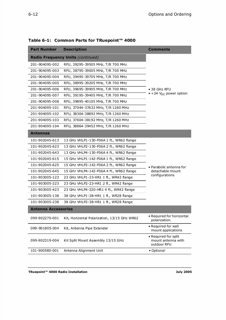
8/10/2019 Hariis TRuepoint 4000 - The Radio Installation
http://slidepdf.com/reader/full/hariis-truepoint-4000-the-radio-installation 92/118
TRuepoint™ 4000 Radio Installation July 2005
6-12 Options and Ordering
Radio Frequency Units (continued)
• 38 GHz RFU• +24 VDC power option
201-904095-002 RFU, 39295-39505 MHz, T/R 700 MHz
201-904095-003 RFU, 38795-39005 MHz, T/R 700 MHz
201-904095-004 RFU, 39495-39705 MHz, T/R 700 MHz
201-904095-005 RFU, 38995-39205 MHz, T/R 700 MHz
201-904095-006 RFU, 39695-39905 MHz, T/R 700 MHz
201-904095-007 RFU, 39195-39405 MHz, T/R 700 MHz
201-904095-008 RFU, 39895-40105 MHz, T/R 700 MHz
201-904095-101 RFU, 37044-37632 MHz, T/R 1260 MHz
201-904095-102 RFU, 38304-38892 MHz, T/R 1260 MHz
201-904095-103 RFU, 37604-38192 MHz, T/R 1260 MHz
201-904095-104 RFU, 38864-39452 MHz, T/R 1260 MHz
Antennas
101-902045-613 13 GHz VHLP1-130-F06A 1 ft., WR62 flange
• Parabolic antenna fordetachable mountconfigurations
101-902045-623 13 GHz VHLP2-130-F06A 2 ft., WR62 flange
101-902045-643 13 GHz VHLP4-130-F06A 4 ft., WR62 flange
101-902045-615 15 GHz VHLP1-142-F06A 1 ft., WR62 flange
101-902045-625 15 GHz VHLP2-142-F06A 2 ft., WR62 flange101-902045-645 15 GHz VHLP4-142-F06A 4 ft., WR62 flange
101-903005-123 23 GHz VHLP1-23-HR1 1 ft., WR42 flange
101-903005-223 23 GHz VHLP2-23-HR1 2 ft., WR42 flange
101-903005-423 23 GHz VHLP4-220-HR1 4 ft., WR42 flange
101-903005-138 38 GHz VHLP1-38-HR1 1 ft., WR28 flange
101-903005-238 38 GHz VHLP2-38-HR1 1 ft., WR28 flange
Antenna Accessories
099-902270-001 Kit, Horizontal Polarization, 13/15 GHz WR62• Required for horizontal
polarization.
099-901805-004 Kit, Antenna Pipe Extender• Required for wall
mount applications
099-902319-004 Kit Split Mount Assembly 13/15 GHz• Required for split
mount antenna withoutdoor RFU
101-900580-001 Antenna Alignment Unit • Optional
Table 6-1: Common Parts for TRuepoint™ 4000
Part Number Description Comments
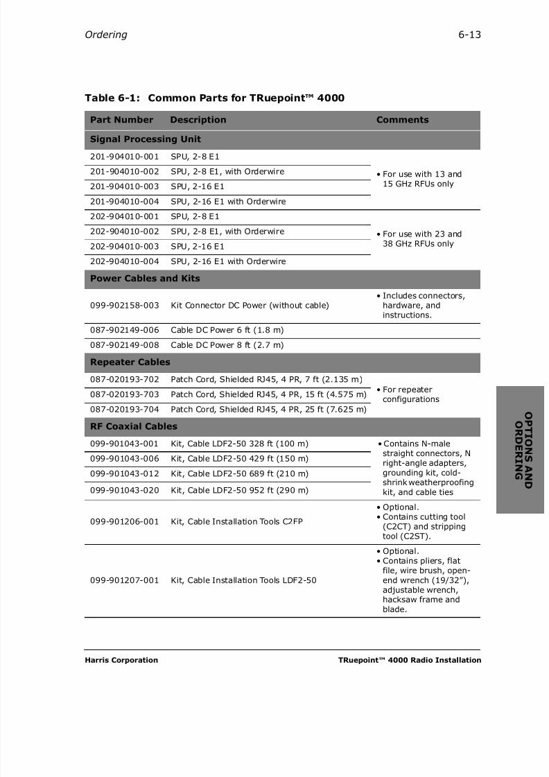
8/10/2019 Hariis TRuepoint 4000 - The Radio Installation
http://slidepdf.com/reader/full/hariis-truepoint-4000-the-radio-installation 93/118
Harris Corporation TRuepoint™ 4000 Radio Installation
Ordering 6-13
Signal Processing Unit
201-904010-001 SPU, 2-8 E1
• For use with 13 and15 GHz RFUs only
201-904010-002 SPU, 2-8 E1, with Orderwire
201-904010-003 SPU, 2-16 E1
201-904010-004 SPU, 2-16 E1 with Orderwire
202-904010-001 SPU, 2-8 E1
• For use with 23 and38 GHz RFUs only
202-904010-002 SPU, 2-8 E1, with Orderwire
202-904010-003 SPU, 2-16 E1
202-904010-004 SPU, 2-16 E1 with Orderwire
Power Cables and Kits
099-902158-003 Kit Connector DC Power (without cable)• Includes connectors,
hardware, andinstructions.
087-902149-006 Cable DC Power 6 ft (1.8 m)
087-902149-008 Cable DC Power 8 ft (2.7 m)
Repeater Cables
087-020193-702 Patch Cord, Shielded RJ45, 4 PR, 7 ft (2.135 m)• For repeater
configurations087-020193-703 Patch Cord, Shielded RJ45, 4 PR, 15 ft (4.575 m)
087-020193-704 Patch Cord, Shielded RJ45, 4 PR, 25 ft (7.625 m)
RF Coaxial Cables
099-901043-001 Kit, Cable LDF2-50 328 ft (100 m) •Contains N-malestraight connectors, Nright-angle adapters,grounding kit, cold-shrink weatherproofingkit, and cable ties
099-901043-006 Kit, Cable LDF2-50 429 ft (150 m)
099-901043-012 Kit, Cable LDF2-50 689 ft (210 m)
099-901043-020 Kit, Cable LDF2-50 952 ft (290 m)
099-901206-001 Kit, Cable Installation Tools C2FP
• Optional.• Contains cutting tool
(C2CT) and stripping
tool (C2ST).
099-901207-001 Kit, Cable Installation Tools LDF2-50
• Optional.• Contains pliers, flat
file, wire brush, open-end wrench (19/32”),adjustable wrench,hacksaw frame andblade.
Table 6-1: Common Parts for TRuepoint™ 4000
Part Number Description Comments

8/10/2019 Hariis TRuepoint 4000 - The Radio Installation
http://slidepdf.com/reader/full/hariis-truepoint-4000-the-radio-installation 94/118
TRuepoint™ 4000 Radio Installation July 2005
6-14 Options and Ordering
RF Coaxial Cables (continued)• Contains cable, sealing
kit, N-male straightconnectors, groundingkits, and cable ties
099-901208-002 Kit, Cable C2FP RG-8/U 300 ft (91.4 m)
099-901208-003 Kit, Cable C2FP RG-8/U 500 ft (152.4 m)
099-901208-004 Kit, Cable C2FP RG-8/U 700 ft (210 m)
099-920248-002 Kit, Cable C2FP L=500 m (on 1 reel) • Contains cable on reel,10 sealing kits, 10 N-male straightconnectors,10 grounding kits, andcable ties
099-920248-004 Kit, Cable C2FP L=1000 m (on 2 reels)
Tributary Cables and Kits
087-901210-003 Cable Harness Unbalanced 8 E1 4.9 ft (1.5 m)• For balanced configs.• Right angle connector-
to-stub end
087-901346-002 Cable Harness Unbalanced 1.5 ft (0.46 m) 8E1 • For unbalancedconfigurations
• Cable has right angle-to-BNC connectors
087-901346-004 Cable Harness Unbalanced 9 ft (2.75 m) 8E1
098-901250-001 Kit, Cable Balanced 32.5 ft (10 m)• For balanced
configurations.• Right angle connector-
to-stub end
098-901250-002 Kit, Cable Balanced 10 ft (3 m)
098-901250-003 Kit, Cable Balanced 20 ft (6 m)
098-901250-004 Kit, Cable Balanced 100 ft (30 m)
Connectivity Cables and Adapters
087-902875-001 Cable RJ45 Male-RJ45 Female 0.5 ft (0.15 m)• For data connection to
Constellation.
087-903013-001 Cable RJ45 Male-RJ45 Female 0.5 ft (0.15 m)• For voice connection to
Constellation.
087-902907-001 Cable RJ45 Male-RJ45 Male 7 ft (2.14 m)• For Data, Voice, and
SCAN connections toMicroStar® Type II.
087-902907-002 Cable RJ45 Male-RJ45 Male 15 ft (4.58 m)
087-902907-003 Cable RJ45 Male-RJ45 Male 25 ft (7.63 m)
087-900306-001 Cable DB9 Male-DB9 Male 10 ft (3.05) • Select one. Requiredfor connection toMegastar.
087-900306-002 Cable DB9 Male-DB9 Male 25 ft (7.63 m)
087-900306-100 Cable DB9 Male-DB0 Male 10 inch, (0.25 m)
042-900603-001 Adapter DB-9 Male-RJ-45 Jack• For 100 Base T
configuration.
042-020063-012 Connector Adapter R/A N-Jack #UG27C/U
Table 6-1: Common Parts for TRuepoint™ 4000
Part Number Description Comments

8/10/2019 Hariis TRuepoint 4000 - The Radio Installation
http://slidepdf.com/reader/full/hariis-truepoint-4000-the-radio-installation 95/118
Harris Corporation TRuepoint™ 4000 Radio Installation
Ordering 6-15
Miscellaneous Accessories (Optional)
091-020085-107 Hand Set Phone WH • For voice orderwire.
098-903054-001 Kit Cap ESD 50 Pin• To protect an unused
tributary port on a2-16 E1
098-903030-002 Kit Display Key Pad 1.8 M Straight
• For networkmanagement. Containskeypad and straightcable.
098-903055-001 Kit, Cable Straight 3M• For display/keypad.
098-903055-002 Kit, Cable Coil
098-093607-030 Kit SMA Connector• Contains SMA
connector andhardware.
098-020016-260 Kit Wire Wrap Adapter
098-093607-026 Kit Wrench
098-093607-001 Kit Sealing Cold Shrink• For outdoor coaxial
cable.
099-901351-001 Kit Install Rack Mount Shelf • Hardware for SPU rack
mounting.
101-901415-001 L/I Unbalanced Panel 2 E1 / 4 E1
• For unbalanced
configurations. Cannotexpand higher than4E1.
101-901415-002 L/I Unbalanced Panel 8 E1• For unbalanced
configurations. For 8-16E1, quantity is 2.
103-097885-416 Andrew Ground Kit #223158• For LDF2-50 coaxial
cable.
Provisioned Traffic Capacities and Options
301-904040-001 2E1 License Provision
• Select one.
301-904041-001 4E1 License Provision
301-904042-001 8 E1 License Provision
301-904043-001 16 E1 License Provision
301-904039-001 100 Base-T License Provision • Optional.
Table 6-1: Common Parts for TRuepoint™ 4000
Part Number Description Comments

8/10/2019 Hariis TRuepoint 4000 - The Radio Installation
http://slidepdf.com/reader/full/hariis-truepoint-4000-the-radio-installation 96/118
TRuepoint™ 4000 Radio Installation July 2005
6-16 Options and Ordering
User Documentation and Software
IMN-904006-E0x System Description Manual (Hard Copy)
• Optional.IMN-904007-E0x Installation Manual (Hard Copy)
IMN-904008-E0x Operator Interface Manual (Hard Copy)
QRC-904009-E0x Quick Reference Card (Hard Copy) •Qty 1 per SPU.
CDR-904005-E0x Customer Publication Set (On CD)• Qty 1 per system (min)• Qty 1 per 20 sites.
CDR-904025-00x System Software• CD Media.• Qty 1 per system (min)
• Qty 1 per 20 sites.
Table 6-1: Common Parts for TRuepoint™ 4000
Part Number Description Comments

8/10/2019 Hariis TRuepoint 4000 - The Radio Installation
http://slidepdf.com/reader/full/hariis-truepoint-4000-the-radio-installation 97/118
Harris Corporation TRuepoint™ 4000 Radio Installation
Ordering 6-17
Customer Service Information
Standard Customer Service Support Guidelines
Harris MCD offers many after-sales services such as Technical Assistance,Repair and Advance Replacements. For details on our services, policies,procedures and how to reach us, please visit our web site athttps://premier.harris.com/microwave/ and access the Worldwide Customer
Service – Support Guidelines Document . If you cannot access our web site,please call us at 1-800-227-8332 (514-421-8333) or email us [email protected] to get a copy.
Services Offered
• Technical assistance from highly qualified Product Support engineersto resolve technical questions / problems on the phone.
• Field Service support to resolve equipment problems on site by highlyprofessional Field Service engineers.
• Repair of equipment at our Repair & Return facilities in a timely andcost-effective manner.
• Customers may benefit from the Harris MCD Refurbish and RetuneProgram to ensure that their systems will continue to operate at optimalperformance as well as benefit from the latest engineeringimprovements which we continue to implement into Harris MCDproducts.
• 24-hour emergency telephone support by highly qualified ProductSupport engineers for traffic affecting or traffic threatening problems.
• 24-hour emergency shipment of replacement parts on selected items tominimize downtime.
• Product training by highly qualified instructors that maximizes productperformance and minimizes maintenance costs.

8/10/2019 Hariis TRuepoint 4000 - The Radio Installation
http://slidepdf.com/reader/full/hariis-truepoint-4000-the-radio-installation 98/118
TRuepoint™ 4000 Radio Installation July 2005
6-18 Options and Ordering
Technical Assistance Centre
Technical support is available 24 hours per day, seven days a week, 365 daysper year. Product Support Engineers are available worldwide to help you with
your technical questions or problems. For the USA/Canada, call us at1-800-227-8332. For International, call the Technical Assistance Centre near
you or contact us at 1-514-421-8333, fax to 1-514-421-3555 or email us [email protected].
Please provide us with the following information when you call:
1. Your name, company and telephone number.
2. Equipment type and Sales Order number or FWL number found at the bottom of the rack.
3. Detailed description of the problem.
Repair and Returns Services
Harris MCD repairs all its manufactured products as well as coordinatesrepairs on vendor items which are part of its systems. The typical repair turnaround time for current production models is 5 working days upon receipt ofthe defective parts and 15 working days for Manufacture Discontinued items,subject to the availability of parts (some restrictions apply).
Repair charges and turn around time for OEM (vendor) items are set by HarrisMCD suppliers. Our close working relationships with our suppliers assure us ofthe best repair prices and turn around time.
For more details, contact us in the USA/Canada at 1-800-227-8332, for otherregions, contact the Harris Repair and Return centre nearest you, or call us at1-514-421-8333, fax your request to 1-514-421-3555 or email us [email protected].
On-Site Field Service Support
Harris MCD factory trained Field Service engineers are available to performon-site technical assistance on an as needed basis when telephone assistancecan not be effectively rendered. All request for on-site assistance should bemade to the Technical Assistance Center. Call the Technical Assistance Centernearest you or directly call our U.S.A. TAC office at1-800-227-8332 (1-650-594-3800) or email us at [email protected].

8/10/2019 Hariis TRuepoint 4000 - The Radio Installation
http://slidepdf.com/reader/full/hariis-truepoint-4000-the-radio-installation 99/118
Harris Corporation TRuepoint™ 4000 Radio Installation
Ordering 6-19
Annual Repair Service Program (ARSP)
Our ARSP service will assure you that all your repairs will be covered for aminimal fee paid up front. Repairs will be processed immediately andunexpected large repair expenses will be avoided. Only Harris MCDmanufactured units are covered by the Annual Repair Service Program. Theantenna system as well as OEM equipment like the channel banks are excluded.Th i s w a r r a n t y e x t en s i o n ex cl u d es an y un i t s d eem ed “ i r r ep a r a b l e ”
d ue t o m i s u se o r a bu s e o f t h e un i t s a n d r ep l a c em en t o f p a r t s
su b j e ct t o n o rm a l w ea r a n d t e a r . Equipment must be in good operatingcondition prior to purchasing a warranty extension service. For a morecomplete warranty coverage (including OEM equipment), please refer to oursection titled Maintenance Level Agreements (MLA).
For more details please visit our web site at
https://premier.harris.com/microwave/ and access the Datasheet “AnnualRepair Service Program”. For pricing information you can contact us at1-800-227-8332 (514-421-8333) or email us at [email protected].
Maintenance Level Agreements (MLA)
Harris MCD’s Maintenance Level Agreements (MLA) provide ongoing supportfor Harris hardware, software and OEM products beyond the expiration ofstandard warranties. This comprehensive network maintenance program
ensures that Harris-supplied networks will continue to perform criticalfunctions, providing the peace of mind our customers expect.
For more details please visit our web site athttps://premier.harris.com/microwave/ and access the Datasheet“Maintenance Level Agreements (MLA)” . For pricing information you cancontact us at 1-800-227-8332 (514-421-8333) or email us [email protected].
Customer Training
Harris MCD offers operation and maintenance courses for microwave,lightwave, multiplex and network operation and management systems. Thecourses are designed to maximize product performance and minimizemaintenance costs. Regular classes are held in some of our North-Americanand International facilities. For information on currently available courses,pricing and training locations, please visit our WEB site athttp://www.microwave.harris.com/support/training/ or e-mail us [email protected].

8/10/2019 Hariis TRuepoint 4000 - The Radio Installation
http://slidepdf.com/reader/full/hariis-truepoint-4000-the-radio-installation 100/118
TRuepoint™ 4000 Radio Installation July 2005
6-20 Options and Ordering

8/10/2019 Hariis TRuepoint 4000 - The Radio Installation
http://slidepdf.com/reader/full/hariis-truepoint-4000-the-radio-installation 101/118
Harris Corporation TRuepoint™ 4000 Radio Installation
C H A P T E R
7GLOSSARY
This chapter provides an expanded description(as appropriate) of most of the acronyms used in theTRuepoint™ 4000 user documentation.
AGC Automatic Gain Control
ATPC Automatic Transmit Power Control — A feature of digital microwave radioequipment that adjusts the transmitter output power based on path fading
detected at the receiver.DTPC Dynamic Transmit Power Control — A feature enabling the regulation of a target
receive signal level by remotely and proportionally controlling the correspondingtransmitter output power level.
FEC Forward Error Correction — A coding technique that compensates for a noisytransmission channel by sending, along with the primary data payload, additionalinformation to correct for errors that occur in transmission.
HDLC High-level Data Link Control — A bit-oriented synchronous data link layerprotocol developed by ISO. HDLC specifies a data encapsulation method onsynchronous serial links using frame characters and checksums.
HHT Handheld terminal — A Harris’ user interface device (also known as a displaykeypad). It allows the user to configure and monitor the radio when not using
CIT or Web-CIT.IF Intermediate Frequency
IP Internet Protocol — A method or protocol by which data is sent from onecomputer to another on the Internet.
LAN Local-area Network — A data network located on a user's premises within alimited geographical area. Widely used technology standards in LANs areEthernet, FDDI, and Token Ring.

8/10/2019 Hariis TRuepoint 4000 - The Radio Installation
http://slidepdf.com/reader/full/hariis-truepoint-4000-the-radio-installation 102/118
TRuepoint™ 4000 Radio Installation July 2005
7-2 Glossary
MSUU Microwave Software Upgrade Utility — A Harris’ proprietary software utility forupgrading the software and firmware of the TRuepoint™ radios. Uses MicrosoftWindows 2000® Service Pack 4 or later.
MUX Multiplexer — A circuitry that combines two or more information-carryingchannels for transmission over one channel, by using frequency division or timedivision techniques
NMS Network Management System — such as Harris’ StarView™.
PDH Plesiosynchronous Digital Hierarchy — A complex multiplexing scheme of bitstuffing and byte interleaving. It multiplexes the lower level 64 kbit/s circuitsinto a successively higher order 2 Mbit/s, 34 Mbit/s, 140 Mbit/s and 565 Mbit/saggregate rates.
QAM Quadrature Amplitude Modulation
QPSK Quadrature Phase Shift Keying
RestrictedArea
A location qualified in accordance with IEC Standard 60950-1 as providing an
access that can only be gained by Skilled Persons or users who have beeninstructed about the reasons for the restriction applied to the location and aboutany precautions to be taken; andaccess achieved through the use of a Tool, lock and key, or other means ofsecurity, and is controlled by the authority responsible for the location.
RFU Radio Frequency Unit
RMS Rack Mounting Space
RSL Received Signal Level
RSSI Received Signal Strength Indicator — A parameter returned from a transceiverthat gives a measure of the RF signal strength.
RTPC Remote Transmit Power Control — A feature that allows an operator to access aremote transmitter and insert an attenuation in the transmitted signal. This isdone through the HHT or Web-CIT.

8/10/2019 Hariis TRuepoint 4000 - The Radio Installation
http://slidepdf.com/reader/full/hariis-truepoint-4000-the-radio-installation 103/118
Harris Corporation TRuepoint™ 4000 Radio Installation
7-3
SkilledPerson
A s k i l l e d p e r s o n is considered to have the necessary knowledge and practicalexperience of electrical and radio engineering to appreciate the various hazardsthat can arise from working on radio transceivers, and takes appropriate
precautions to ensure the safety of personnel.This individual is considered to be a s k i l l e d p e r s o n only if he/she is competentto take responsibility for both his/her safety and for that of unskilled personnelunder his/her immediate supervision, when working on the transceiver.Training requirements for a s k i l l e d p e r s o n should not only be confined totechnical matters and, preferably, should include first-aid treatment, especiallymethods of artificial resuscitation: respiration and cardiac compression (heartmassage).
SNMP Simple Network Management Protocol — Protocol used to facilitate networkmanagement by exchanging information between equipment on a network.
SPU Signal Processing Unit
W eb -CIT Web-Craft Interface Tool — A Harris’ proprietary software utility for monitoringand controlling the operation and configuration of the TRuepoint™ radios.Located on the TRuepoint™ Controller, any of the two NTWRK/LAN ports allowsfor connecting a PC running the Web-CIT server that is embedded in the radio.This web server stores HTML pages and applets that provide a user interface formonitoring and controlling any TRuepoint™ Network Element, using theMicrosoft® Internet Explorer, version 5.5 and later.

8/10/2019 Hariis TRuepoint 4000 - The Radio Installation
http://slidepdf.com/reader/full/hariis-truepoint-4000-the-radio-installation 104/118
TRuepoint™ 4000 Radio Installation July 2005
7-4 Glossary

8/10/2019 Hariis TRuepoint 4000 - The Radio Installation
http://slidepdf.com/reader/full/hariis-truepoint-4000-the-radio-installation 105/118
Harris Corporation TRuepoint™ 4000 Radio Installation
A P P E N D I X
A SPU PORTS’ PINOUTS
Table A-1: Balanced Tributaries 1-8: 50-Pin Female SCSI-1Pin Name Direction Description
1 NC - No connection
2 GND - Ground
3 RRING8 OUT Tributary 8 Output Ring
4 TRING8 IN Tributary 8 Input Ring
5 GND - Ground
6 RRING7 OUT Tributary 7 Output Ring
7 TRING7 IN Tributary 7 Input Ring
8 GND - Ground
9 RRING6 OUT Tributary 6 Output Ring
10 TRING6 IN Tributary 6 Input Ring
11 GND - Ground
12 RRING5 OUT Tributary 5 Output Ring
13 TRING5 IN Tributary 5 Input Ring
14 GND - Ground
15 RRING4 OUT Tributary 4 Output Ring
16 TRING4 IN Tributary 4 Input Ring
17 GND - Ground
18 RRING3 OUT Tributary 3 Output Ring
Pin 26Pin 50
Pin 1
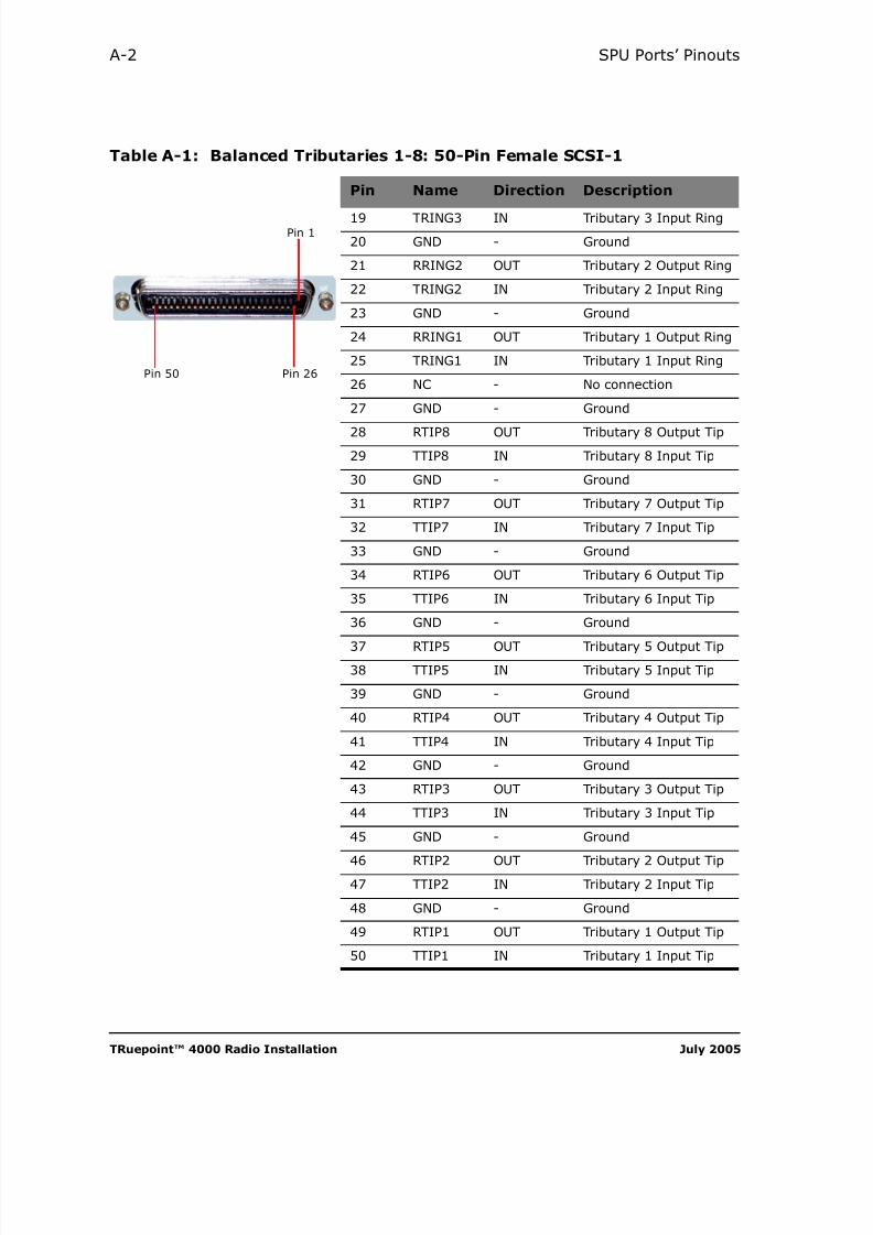
8/10/2019 Hariis TRuepoint 4000 - The Radio Installation
http://slidepdf.com/reader/full/hariis-truepoint-4000-the-radio-installation 106/118
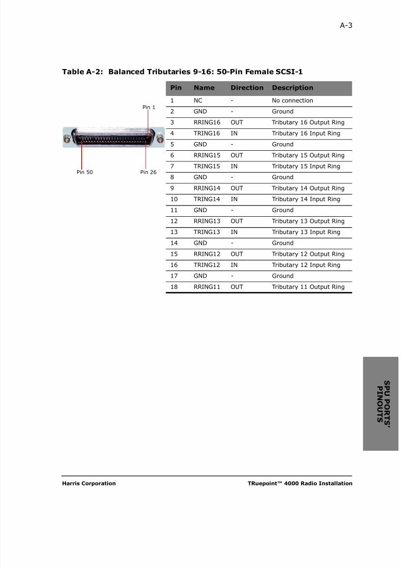
8/10/2019 Hariis TRuepoint 4000 - The Radio Installation
http://slidepdf.com/reader/full/hariis-truepoint-4000-the-radio-installation 107/118
Harris Corporation TRuepoint™ 4000 Radio Installation
A-3
Table A-2: Balanced Tributaries 9-16: 50-Pin Female SCSI-1
Pin Name Direction Description
1 NC - No connection
2 GND - Ground
3 RRING16 OUT Tributary 16 Output Ring
4 TRING16 IN Tributary 16 Input Ring
5 GND - Ground
6 RRING15 OUT Tributary 15 Output Ring
7 TRING15 IN Tributary 15 Input Ring
8 GND - Ground
9 RRING14 OUT Tributary 14 Output Ring
10 TRING14 IN Tributary 14 Input Ring
11 GND - Ground
12 RRING13 OUT Tributary 13 Output Ring
13 TRING13 IN Tributary 13 Input Ring
14 GND - Ground
15 RRING12 OUT Tributary 12 Output Ring
16 TRING12 IN Tributary 12 Input Ring
17 GND - Ground
18 RRING11 OUT Tributary 11 Output Ring
Pin 26Pin 50
Pin 1

8/10/2019 Hariis TRuepoint 4000 - The Radio Installation
http://slidepdf.com/reader/full/hariis-truepoint-4000-the-radio-installation 108/118
TRuepoint™ 4000 Radio Installation July 2005
A-4 SPU Ports’ Pinouts
19 TRING11 IN Tributary 11 Input Ring
20 GND - Ground
21 RRING10 OUT Tributary 10 Output Ring
22 TRING10 IN Tributary 10 Input Ring
23 GND - Ground
24 RRING9 OUT Tributary 9 Output Ring
25 TRING9 IN Tributary 9 Input Ring
26 NC - No Connection
27 GND - Ground
28 RTIP16 OUT Tributary 16 Output Tip
29 TTIP16 IN Tributary 16 Input Tip
30 GND - Ground
31 RTIP15 OUT Tributary 15 Output Tip
32 TTIP15 IN Tributary 15 Input Tip
33 GND - Ground
34 RTIP14 OUT Tributary 14 Output Tip
35 TTIP14 IN Tributary 14 Input Tip
36 GND - Ground
37 RTIP13 OUT Tributary 13 Output Tip
38 TTIP13 IN Tributary 13 Input Tip
39 GND - Ground
40 RTIP12 OUT Tributary 12 Output Tip
41 TTIP12 IN Tributary 12 Input Tip
42 GND - Ground
43 RTIP11 OUT Tributary 11 Output Tip
44 TTIP11 IN Tributary 11 Input Tip
45 GND - Ground
46 RTIP10 OUT Tributary 10 Output Tip
47 TTIP10 IN Tributary 10 Input Tip
48 GND - Ground
49 RTIP9 OUT Tributary 9 Output Tip
50 TTIP9 IN Tributary 9 Input Tip
Table A-2: Balanced Tributaries 9-16: 50-Pin Female SCSI-1
Pin Name Direction Description
Pin 26Pin 50
Pin 1

8/10/2019 Hariis TRuepoint 4000 - The Radio Installation
http://slidepdf.com/reader/full/hariis-truepoint-4000-the-radio-installation 109/118
Harris Corporation TRuepoint™ 4000 Radio Installation
A-5
Table A-3: Unbalanced Tributaries 1-8: 50-Pin Female SCSI-1
Pin Name Direction Description
1 NC - No connection
2 GND - Ground
3 GND - Ground
4 GND - Ground
5 GND - Ground
6 GND - Ground
7 GND - Ground
8 GND - Ground
9 GND - Ground
10 GND - Ground
11 GND - Ground
12 GND - Ground
13 GND - Ground
14 GND - Ground
15 GND - Ground
16 GND - Ground
17 GND - Ground
18 GND - Ground
Pin 26Pin 50
Pin 1

8/10/2019 Hariis TRuepoint 4000 - The Radio Installation
http://slidepdf.com/reader/full/hariis-truepoint-4000-the-radio-installation 110/118
TRuepoint™ 4000 Radio Installation July 2005
A-6 SPU Ports’ Pinouts
19 GND - Ground
20 GND - Ground
21 GND - Ground
22 GND - Ground
23 GND - Ground
24 GND - Ground
25 GND - Ground
26 NC - No Connection
27 GND - Ground
28 RTIP8 Out Tributary 8 Output Tip
29 TTIP8 In Tributary 8 Input Tip
30 GND - Ground
31 RTIP7 Out Tributary 7 Output Tip
32 TTIP7 In Tributary 7 Input Tip
33 GND - Ground
34 RTIP6 Out Tributary 6 Output Tip
35 TTIP6 In Tributary 6 Input Tip
36 GND - Ground
37 RTIP5 Out Tributary 5 Output Tip
38 TTIP5 In Tributary 5 Input Tip
39 GND - Ground
40 RTIP4 Out Tributary 4 Output Tip
41 TTIP4 In Tributary 4 Input Tip
42 GND - Ground
43 RTIP3 Out Tributary 3 Output Tip
44 TTIP3 In Tributary 3 Input Tip
45 GND - Ground
46 RTIP2 Out Tributary 2 Output Tip
47 TTIP2 In Tributary 2 Input Tip
48 GND - Ground
49 RTIP1 Out Tributary 1 Output Tip
50 TTIP1 In Tributary 1 Input Tip
Table A-3: Unbalanced Tributaries 1-8: 50-Pin Female SCSI-1
Pin Name Direction Description
Pin 26Pin 50
Pin 1

8/10/2019 Hariis TRuepoint 4000 - The Radio Installation
http://slidepdf.com/reader/full/hariis-truepoint-4000-the-radio-installation 111/118
Harris Corporation TRuepoint™ 4000 Radio Installation
A-7
Table A-4: Unbalanced Tributaries 9-16: 50-Pin Female SCSI-1
Pin Name Direction Description
1 NC - No connection
2 GND - Ground
3 GND - Ground
4 GND - Ground
5 GND - Ground
6 GND - Ground
7 GND - Ground
8 GND - Ground
9 GND - Ground
10 GND - Ground
11 GND - Ground
12 GND - Ground
13 GND - Ground
14 GND - Ground
15 GND - Ground
16 GND - Ground
17 GND - Ground
18 GND - Ground
Pin 26Pin 50
Pin 1
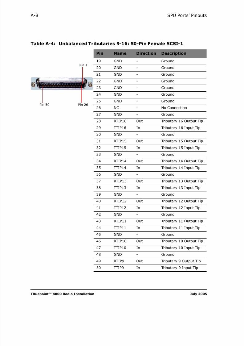
8/10/2019 Hariis TRuepoint 4000 - The Radio Installation
http://slidepdf.com/reader/full/hariis-truepoint-4000-the-radio-installation 112/118
TRuepoint™ 4000 Radio Installation July 2005
A-8 SPU Ports’ Pinouts
19 GND - Ground
20 GND - Ground
21 GND - Ground
22 GND - Ground
23 GND - Ground
24 GND - Ground
25 GND - Ground
26 NC - No Connection
27 GND - Ground
28 RTIP16 Out Tributary 16 Output Tip
29 TTIP16 In Tributary 16 Input Tip
30 GND - Ground
31 RTIP15 Out Tributary 15 Output Tip
32 TTIP15 In Tributary 15 Input Tip
33 GND - Ground
34 RTIP14 Out Tributary 14 Output Tip
35 TTIP14 In Tributary 14 Input Tip
36 GND - Ground
37 RTIP13 Out Tributary 13 Output Tip
38 TTIP13 In Tributary 13 Input Tip
39 GND - Ground
40 RTIP12 Out Tributary 12 Output Tip
41 TTIP12 In Tributary 12 Input Tip
42 GND - Ground
43 RTIP11 Out Tributary 11 Output Tip
44 TTIP11 In Tributary 11 Input Tip
45 GND - Ground
46 RTIP10 Out Tributary 10 Output Tip
47 TTIP10 In Tributary 10 Input Tip
48 GND - Ground
49 RTIP9 Out Tributary 9 Output Tip
50 TTIP9 In Tributary 9 Input Tip
Table A-4: Unbalanced Tributaries 9-16: 50-Pin Female SCSI-1
Pin Name Direction Description
Pin 26Pin 50
Pin 1

8/10/2019 Hariis TRuepoint 4000 - The Radio Installation
http://slidepdf.com/reader/full/hariis-truepoint-4000-the-radio-installation 113/118
Harris Corporation TRuepoint™ 4000 Radio Installation
A-9
Table A-5: HDLC (RJ-45), MicroStar® / Constellation® Net_Comm Port
Pin Name Direction Description
1 NWTXCLKPController toEquipment
RS-422,Net West clock transmit, positive
2 NWTXCLKNController toEquipment
RS-422,Net West clock transmit, negative
3 NWTXPController toEquipment
RS-422,Net West transmit signal, positive
4 NWTXNController toEquipment
RS-422,Net West transmit signal, negative
5 NWRXCKPEquipmentto Controller
RS-422,Net West clock receive, positive
6 NWRXCKN Equipmentto Controller RS-422,Net West clock receive, negative
7 NWRXPEquipmentto Controller
RS-422,Net West receive signal, positive
8 NWRXNEquipmentto Controller
RS-422,Net West receive signal, negative
Pin 8Pin 1
HDLC
Table A-6: Port 1 (RJ-45), Data and Local Communications (Future)
Pin Name Direction Description
1 NO CONNECTION
2 NO CONNECTION
3 NO CONNECTION
4 GND GND to GND Ground
5 RX_DATControllerto PC
RS232, data receive
6 TX_DATPC toController
RS232, data transmit
7 NO CONNECTION
8 NO CONNECTION
Pin 8 Pin 1
Port 1

8/10/2019 Hariis TRuepoint 4000 - The Radio Installation
http://slidepdf.com/reader/full/hariis-truepoint-4000-the-radio-installation 114/118
TRuepoint™ 4000 Radio Installation July 2005
A-10 SPU Ports’ Pinouts
Table A-7: Port 2 (RJ-45), HHT and VT-100 Terminals
Pin Name Direction Description
1 DISPLAY_+5VHHT/VT-100to CTL
HHT Power Input
2 NO CONNECTION
3 NO CONNECTION
4 GND GND-GND Ground
5 RX_DATCTL toHHT/VT-100
RS232, data receive
6 TX_DATHHT/VT-100to CTL
RS232, data transmit
7 NO CONNECTION
8 NO CONNECTION
Pin 8Pin 1
Port 2
Table A-8: NTWRK / LAN, (RJ-45), Repeater and Network Management
Pin Name Direction Description
1 ETHER_RXA_P In 10/100BASE-T Input
2 ETHER_RXA_N In 10/100BASE-T Input
3 ETHER_TXA_P Out 10/100BASE-T Output
4 Tied to chassis via a 75 ohm and
cap5
6 ETHER_TXA_N Out 10/100BASE-T Output
7 Tied to chassis via a 75 ohm andcap8
1 ETHER_RXB_P In 10/100BASE-T Input
2 ETHER_RXB_N In 10/100BASE-T Input
3 ETHER_TXB_P Out 10/100BASE-T Output
4 Tied to chassis via a 75 ohm andcap5
6 ETHER_TXB_N Out 10/100BASE-T Output
7 Tied to chassis via a 75 ohm andcap8
* The 88E6052 include the Auto MDI/MDIX Crossover for each port
Pin 8 Pin 1
NTWRK/LAN 1
Pin 8Pin 1
NTWRK/LAN 2
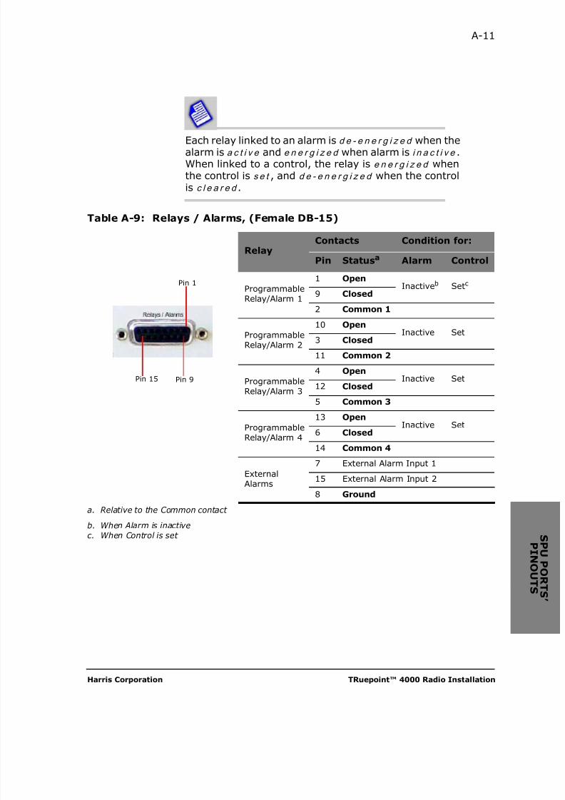
8/10/2019 Hariis TRuepoint 4000 - The Radio Installation
http://slidepdf.com/reader/full/hariis-truepoint-4000-the-radio-installation 115/118
Harris Corporation TRuepoint™ 4000 Radio Installation
A-11
Each relay linked to an alarm is d e - e n e r g i z e d when thealarm is a c t i v e and e n e r g i z e d when alarm is i n a c t i v e .When linked to a control, the relay is e n e r g i z e d whenthe control is s e t , and d e - e n e r g i z e d when the controlis c l e a r e d .
Table A-9: Relays / Alarms, (Female DB-15)
RelayContacts Condition for:
Pin Statusa Alarm Control
ProgrammableRelay/Alarm 1
1 Open Inactiveb Setc9 Closed
2 Common 1
ProgrammableRelay/Alarm 2
10 OpenInactive Set
3 Closed
11 Common 2
ProgrammableRelay/Alarm 3
4 OpenInactive Set
12 Closed
5 Common 3
ProgrammableRelay/Alarm 4
13 Open Inactive Set6 Closed
14 Common 4
ExternalAlarms
7 External Alarm Input 1
15 External Alarm Input 2
8 Ground
a. Relative to the Common contact
b. When Alarm is inactivec. When Control is set
Pin 9Pin 15
Pin 1

8/10/2019 Hariis TRuepoint 4000 - The Radio Installation
http://slidepdf.com/reader/full/hariis-truepoint-4000-the-radio-installation 116/118
TRuepoint™ 4000 Radio Installation July 2005
A-12 SPU Ports’ Pinouts
Table A-10:Orderwire, 4W (RJ-45), External Auxiliary Channels Interface
Pin Name Direction Description
1 GND Ground connection
2 GND Ground connection
3 IN In Differential positive analog input
4 OUT Out Differential negative analog output
5 OUT Out Differential negative analog output
6 IN In Differential positive analog input
7 GND Ground connection
8 GND Ground connection
P n 1
Table A-11:Orderwire, 2W (RJ-11) Voice
Pin Name Direction Description
1 GND Ground connection
2 TIP In 2-Wire Input Tip
3 RING In 2-Wire Input Ring
4 GND Ground connection
Pin 1

8/10/2019 Hariis TRuepoint 4000 - The Radio Installation
http://slidepdf.com/reader/full/hariis-truepoint-4000-the-radio-installation 117/118
Harris Corporation TRuepoint™ 4000 Radio Installation
INDEX
A
ATPC 7-1
B
BERT set 4-21
C
CableBNC 4-13coaxial, allowable length 2-10connecor on SPU 2-4connectorized 4-14connectors, N-type 2-8grounding 4-7network, RJ-45 4-16power 4-9RFU to SPU 3-12tools for installing 3-3typical run 3-13
Control A-11
control 4-15
Customer Training 6-19
E
EMIspecifications 2-9
F
Foreword 1-1
G
General Specifications 2-5
I
Installation Types 3-2Installing
RFU Outdoors, Detachable Mount 3-16
InterconnectivityMicroStar® 4-15
ISO 9001 -v
K
Key FeaturesTRuepoint™ 5000 RFU 1-3
M
Maintenance 5-1
ModulationQAM 7-2
MUX and SDM ports, Tributaries, Seealso Tributaries A-5
O
On-Site Field Service Repair 6-18
Ordering 6-1
P
PartsNumbers v/ Product Codes 6-1ordering 6-2Spare 6-1
Placing the order 6-2
Polarizationhorizontal 3-7setting antenna 3-6, 3-8vertical 3-7, 3-9
Portscable, on RFU 4-5identification 2-4pinouts A-1tributaries 4-14
Q
Qualifications of Installation Personnel
3-2

8/10/2019 Hariis TRuepoint 4000 - The Radio Installation
http://slidepdf.com/reader/full/hariis-truepoint-4000-the-radio-installation 118/118
I-2 Index
R
Related Manuals 1-4
Repair 6-18Replacing
Units 5-3
RFUinstalling outdoors 3-3latching to antenna 3-11
RFU coaxial cable to SPU 3-12
RSSIvoltage 4-20
S
Site Requirements 3-1Spare
Unit Ordering 6-1
SpecificationsEMC and safety 2-9
SPULEDs 2-4system characteristics 2-8
Standard Product Warranty 6-17
T
Technical Assistance Center -v
training 6-19
Tributaries 4-21