harmonic coordinates for character articulationmisha/readingseminar/papers/joshi07.pdf ·...
TRANSCRIPT
ACM Reference FormatJoshi, P., Meyer, M., DeRose, T., Green, B., Sanocki, T. 2007. Harmonic Coordinates for Character Articula-tion. ACM Trans. Graph. 26, 3, Article 71 (July 2007), 9 pages. DOI = 10.1145/1239451.1239522 http://doi.acm.org/10.1145/1239451.1239522.
Copyright NoticePermission to make digital or hard copies of part or all of this work for personal or classroom use is granted without fee provided that copies are not made or distributed for profi t or direct commercial advantage and that copies show this notice on the fi rst page or initial screen of a display along with the full citation. Copyrights for components of this work owned by others than ACM must be honored. Abstracting with credit is permitted. To copy otherwise, to republish, to post on servers, to redistribute to lists, or to use any component of this work in other works requires prior specifi c permission and/or a fee. Permissions may be requested from Publications Dept., ACM, Inc., 2 Penn Plaza, Suite 701, New York, NY 10121-0701, fax +1 (212) 869-0481, or [email protected].© 2007 ACM 0730-0301/2007/03-ART71 $5.00 DOI 10.1145/1239451.1239522 http://doi.acm.org/10.1145/1239451.1239522
Harmonic Coordinates for Character Articulation
Pushkar Joshi Mark Meyer Tony DeRoseBrian Green Tom Sanocki
Pixar Animation Studios
(a) (b) (c)
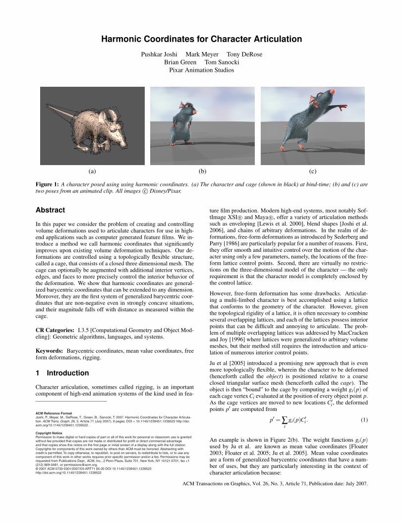
Figure 1: A character posed using using harmonic coordinates. (a) The character and cage (shown in black) at bind-time; (b) and (c) aretwo poses from an animated clip. All images c© Disney/Pixar.
Abstract
In this paper we consider the problem of creating and controllingvolume deformations used to articulate characters for use in high-end applications such as computer generated feature films. We in-troduce a method we call harmonic coordinates that significantlyimproves upon existing volume deformation techniques. Our de-formations are controlled using a topologically flexible structure,called a cage, that consists of a closed three dimensional mesh. Thecage can optionally be augmented with additional interior vertices,edges, and faces to more precisely control the interior behavior ofthe deformation. We show that harmonic coordinates are general-ized barycentric coordinates that can be extended to any dimension.Moreover, they are the first system of generalized barycentric coor-dinates that are non-negative even in strongly concave situations,and their magnitude falls off with distance as measured within thecage.
CR Categories: I.3.5 [Computational Geometry and Object Mod-eling]: Geometric algorithms, languages, and systems.
Keywords: Barycentric coordinates, mean value coordinates, freeform deformations, rigging.
1 Introduction
Character articulation, sometimes called rigging, is an importantcomponent of high-end animation systems of the kind used in fea-
ture film production. Modern high-end systems, most notably Sof-tImage XSI R© and Maya R©, offer a variety of articulation methodssuch as enveloping [Lewis et al. 2000], blend shapes [Joshi et al.2006], and chains of arbitrary deformations. In the realm of de-formations, free-form deformations as introduced by Sederberg andParry [1986] are particularly popular for a number of reasons. First,they offer smooth and intuitive control over the motion of the char-acter using only a few parameters, namely, the locations of the free-form lattice control points. Second, there are virtually no restric-tions on the three-dimensional model of the character — the onlyrequirement is that the character model is completely enclosed bythe control lattice.
However, free-form deformation has some drawbacks. Articulat-ing a multi-limbed character is best accomplished using a latticethat conforms to the geometry of the character. However, giventhe topological rigidity of a lattice, it is often necessary to combineseveral overlapping lattices, and each of the lattices possess interiorpoints that can be difficult and annoying to articulate. The prob-lem of multiple overlapping lattices was addressed by MacCrackenand Joy [1996] where lattices were generalized to arbitrary volumemeshes, but their method still requires the introduction and articu-lation of numerous interior control points.
Ju et al [2005] introduced a promising new approach that is evenmore topologically flexible, wherein the character to be deformed(henceforth called the object) is positioned relative to a coarseclosed triangular surface mesh (henceforth called the cage). Theobject is then “bound” to the cage by computing a weight gi(p) ofeach cage vertex Ci evaluated at the position of every object point p.As the cage vertices are moved to new locations C′i , the deformedpoints p′ are computed from
p′ = ∑i
gi(p)C′i . (1)
An example is shown in Figure 2(b). The weight functions gi(p)used by Ju et al. are known as mean value coordinates [Floater2003; Floater et al. 2005; Ju et al. 2005]. Mean value coordinatesare a form of generalized barycentric coordinates that have a num-ber of uses, but they are particularly interesting in the context ofcharacter articulation because:
ACM Transactions on Graphics, Vol. 26, No. 3, Article 71, Publication date: July 2007.
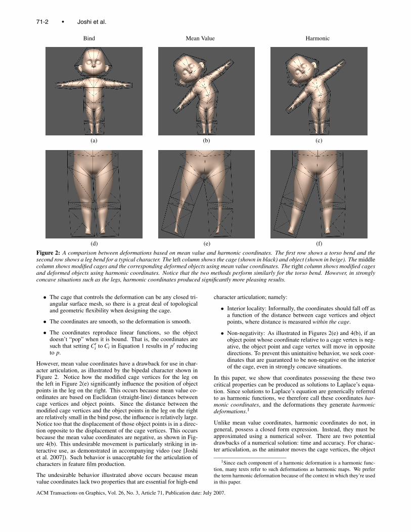
Bind Mean Value Harmonic
(a) (b) (c)
(d) (e) (f)
Figure 2: A comparison between deformations based on mean value and harmonic coordinates. The first row shows a torso bend and thesecond row shows a leg bend for a typical character. The left column shows the cage (shown in black) and object (shown in beige). The middlecolumn shows modified cages and the corresponding deformed objects using mean value coordinates. The right column shows modified cagesand deformed objects using harmonic coordinates. Notice that the two methods perform similarly for the torso bend. However, in stronglyconcave situations such as the legs, harmonic coordinates produced significantly more pleasing results.
• The cage that controls the deformation can be any closed tri-angular surface mesh, so there is a great deal of topologicaland geometric flexibility when designing the cage.
• The coordinates are smooth, so the deformation is smooth.
• The coordinates reproduce linear functions, so the objectdoesn’t “pop” when it is bound. That is, the coordinates aresuch that setting C′i to Ci in Equation 1 results in p′ reducingto p.
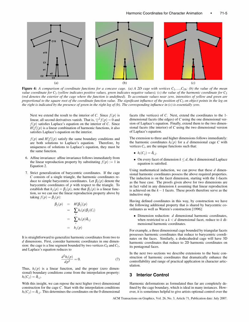
However, mean value coordinates have a drawback for use in char-acter articulation, as illustrated by the bipedal character shown inFigure 2. Notice how the modified cage vertices for the leg onthe left in Figure 2(e) significantly influence the position of objectpoints in the leg on the right. This occurs because mean value co-ordinates are based on Euclidean (straight-line) distances betweencage vertices and object points. Since the distance between themodified cage vertices and the object points in the leg on the rightare relatively small in the bind pose, the influence is relatively large.Notice too that the displacement of those object points is in a direc-tion opposite to the displacement of the cage vertices. This occursbecause the mean value coordinates are negative, as shown in Fig-ure 4(b). This undesirable movement is particularly striking in in-teractive use, as demonstrated in accompanying video (see [Joshiet al. 2007]). Such behavior is unacceptable for the articulation ofcharacters in feature film production.
The undesirable behavior illustrated above occurs because meanvalue coordinates lack two properties that are essential for high-end
character articulation; namely:
• Interior locality: Informally, the coordinates should fall off asa function of the distance between cage vertices and objectpoints, where distance is measured within the cage.
• Non-negativity: As illustrated in Figures 2(e) and 4(b), if anobject point whose coordinate relative to a cage vertex is neg-ative, the object point and cage vertex will move in oppositedirections. To prevent this unintuitive behavior, we seek coor-dinates that are guaranteed to be non-negative on the interiorof the cage, even in strongly concave situations.
In this paper, we show that coordinates possessing the these twocritical properties can be produced as solutions to Laplace’s equa-tion. Since solutions to Laplace’s equation are generically referredto as harmonic functions, we therefore call these coordinates har-monic coordinates, and the deformations they generate harmonicdeformations.1
Unlike mean value coordinates, harmonic coordinates do not, ingeneral, possess a closed form expression. Instead, they must beapproximated using a numerical solver. There are two potentialdrawbacks of a numerical solution: time and accuracy. For charac-ter articulation, as the animator moves the cage vertices, the object
1Since each component of a harmonic deformation is a harmonic func-tion, many texts refer to such deformations as harmonic maps. We preferthe term harmonic deformation because of the context in which they’re usedin this paper.
71-2 • Joshi et al.
ACM Transactions on Graphics, Vol. 26, No. 3, Article 71, Publication date: July 2007.
must deform in real-time. For such fully interactive deformationsthe coordinates should be computed as a pre-process, prior to anyuser interaction. This precomputation is necessary even if a closedform exists, as noted by Ju et al. [2005]. Given that coordinatesmust be precomputed whether or not a closed form exists, the timerequired to run the harmonic coordinate solver is acceptable (seeSections 6 and 7). The key issue regarding accuracy is whether itis possible to reproduce linear functions using reasonable time andspace. For harmonic coordinates this is in fact the case, again asshown in Section 6.
To put our analysis of previous work and contributions in context,we reiterate the problem we are trying to solve and why. Our goalis to develop a topologically flexible “cage-based” method of con-trolling volume deformations. We specifically do not seek a directmanipulation method, such as methods based on local differentialcoordinates (c.f. Sorkine [2006] and Sumner et al. [2005]), thoughwe share some of the same mathematical underpinnings. Whilesuch direct manipulation methods have produced impressive results(particularly under extreme deformations), cage-based methods al-low us to decouple the geometry being articulated (the cage) fromthe geometry of the character. This decoupling is desirable for sev-eral reasons. First, our character models generally do not consist ofa single mesh. Rather, they are typically described using a ratherlarge collection of modeling primitives, including separate meshesfor skin, teeth, and clothing, as well as non-mesh primitives such asspheres for eyeballs. Cage-based methods are ideal for coherentlydeforming such large and diverse collections of primitives, whereasdirect manipulation mesh deformation techniques address the de-formation of individual meshes. Second, the decoupling allows usto reuse the articulation as the character geometry changes. We canalso reuse articulation of the cage to articulate the full version ofthe character, as well as low detail versions for faster preview andrendering. Such reuse of articulation is significant since, at least atour studio, articulation typically takes an order of magnitude longerto author than static geometry.
1.1 Contributions
In this paper we offer the first cage-based deformation techniqueguaranteeing that the influence of each cage vertex is non-negativeand falls off with distance as measured within the cage (see Sec-tion 2). Moreover, it is the first cage-based deformation techniquethat enables users to refine the deformation behavior over the inte-rior of the cage by optionally adding vertices, edges, and faces (seeSection 3). Taken together, these contributions comprise a powerfulnew deformation method for use in high-end character articulation.
1.2 Previous work
Our work lies at the intersection of three large bodies of literature:volume deformations, generalized barycentric coordinates, and har-monic functions. The number of related papers is therefore verylarge. In this section we summarize the most closely related work.
In the area of volume deformations, as mentioned above, Seder-berg and Parry [1986] introduced a method based on three dimen-sional lattices. MacCracken and Joy [1996] subsequently used re-cursive subdivision to achieve more topological flexibility. Similarin spirit to our application where a coarse cage is used to pose acharacter, Capell et al. [2002] use the method of MacCracken andJoy to transfer motion of a coarse subdivision lattice to the geom-etry of a character. Use of subdivision is crucial for their purposessince refinement is used to create the hierarchical basis they useto accelerate the simulation of elastic deformation. However, wewish to avoid subdivision-based methods because, like the origi-nal free-form deformation, they require the interior of the cage to
be meshed, and they contain interior vertices that must be articu-lated. This makes authoring of cage articulation more difficult thancage-based schemes like ours that do not require interior points. Adirect manipulation volume deformation method was introduced byIgarashi et al. [2005]. The deformations they produce are intuitive,but their method does not employ a cage, so the reuse advantagesmentioned above are not realized.
In the area of barycentric coordinates, Ju et al. [2005] used gener-alized barycentric coordinates, specifically, mean value coordinates(see also Floater et al.[2005]) to define deformations controlled bya surface mesh rather than a three dimensional lattice. The prob-lem of generalizing barycentric coordinates is rich and has receivedconsiderable attention in recent years ([Wachpress 1975], [R.Sibson1981], [Loop and DeRose 1989], [Warren 1996], [Meyer et al.2002], [Floater 2003]). Ju et al. [2005] provide a good overview.Our method improves on previous methods by using a different gen-eralized barycentric coordinate formulation, one based on Laplace’sequation.
In the area of harmonic functions, we note that Laplace’s Equation,harmonic functions, and harmonic maps have often been mentionedin previous constructions of generalized barycentric coordinates intwo dimensions. For instance, the “cotangent weights” of Pinkalland Polthier [1993] and Meyer et al. [2002] can be derived frompiecewise linear discretizations of Laplace’s equation. Similarly,Floater’s construction of mean value coordinates [Floater 2003] wasmotivated by the mean value theorem for harmonic functions. In-dependent of our work, Floater and co-workers [2006] recently ob-served that solutions to Laplace’s equation in two dimensions couldbe used as generalized barycentric coordinates. They did not pursuethe observation because their objective was to find a closed-formformulation. However, for character articulation, non-negativityand interior locality are far more important than closed-form ex-pressions. Harmonic coordinates are the only coordinates we areaware of that possess these crucial properties.
Harmonic functions have also been used to define surface defor-mations. For example, Zayer et al. [2005] describe a method fordirect mesh manipulation based on properties of two-dimensionalharmonic functions. Similar to our method, they construct a ba-sis function per controllable vertex, where each function is the re-sult of solving Laplace’s equation subject to Kronecker delta typeconstraints. Shi et al. [2006] extended the method of Zayer et al.by providing a multigrid-based solver. In some sense, our methodcan be seen as combining the benefits of Zayer et al. and Shi etal. with the those of Ju et al.. This combination is far from triv-ial however since we expose the deep connection between gener-alized barycentric coordinates (in any dimension) with harmonicfunctions. We use this connection to create the first cage-based de-formation method with non-negative basis functions and the abilityto specify optional and flexible interior controls.
Finally, harmonic functions have been used in scattered data in-terpolation. For instance, the membrane and thin-plate splines in-troduced by Duchon [1977] are harmonic and bi-harmonic func-tions, respectively, that are used to construct a smooth interpolant(Wahba [1990]). These splines are often used as radial basis func-tions to define coordinates over the interior of a given space. For in-stance, Carr et al. [2001] used polyharmonic spline functions to re-construct smooth 2-manifold surfaces from point clouds, and Choeet al. [2001] used similar splines as a basis function for interpolat-ing marker motion on a human face model. These methods are alldesigned to interpolate at a finite set of points, whereas our methodis designed to interpolate over the entire continuous boundary ofthe cage.
Harmonic Coordinates for Character Animation • 71-3
ACM Transactions on Graphics, Vol. 26, No. 3, Article 71, Publication date: July 2007.
(a)
p
x
(b)
p
x
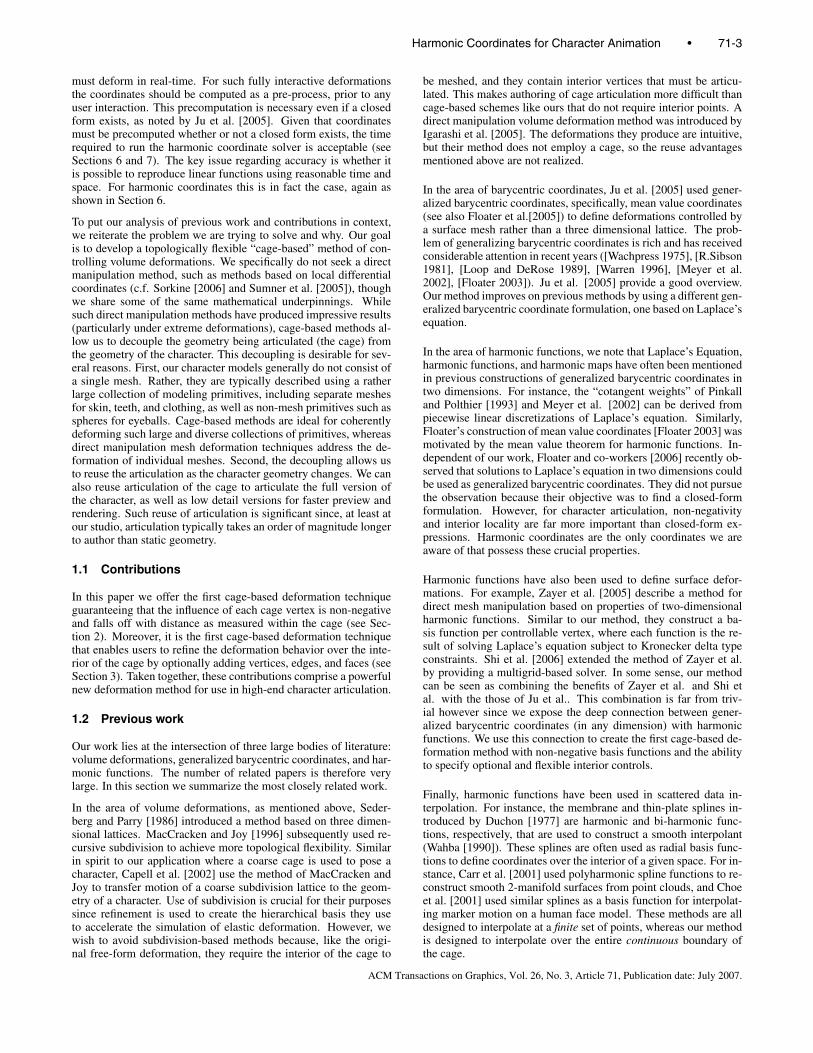
Figure 3: Mean value vs harmonic interpolation. (a) The straight-line paths corresponding to mean value interpolation. (b) TheBrownian paths corresponding to harmonic interpolation.
2 Theory
In this section we formalize the discussion of the previous sectionand prove that harmonic coordinates possess all the properties nec-essary for use in high-end character articulation.
We begin by considering the construction of mean value coordi-nates as described in [Floater et al. 2005] and [Ju et al. 2005]. Theyderive coordinates starting with a “mean value interpolant” of afunction f defined on a closed boundary. To compute an interpolantvalue for each interior point p, they consider each point x on theboundary, multiply f (x) by the reciprocal distance from x to p, thenaverage over all x (see Figure 3(a)). This definition makes it clearthat mean value coordinates involve straight-line distances irrespec-tive of the visibility of x from p. For character articulation, the cageoften has large concavities, and a more useful interpolant would re-spect visibility of an cage vertex from an object point. To constructsuch an interpolant, we can average not over all straight-line paths,but rather over all Brownian paths leaving p, where the value as-signed to each path is the value of f at the point the path first hitsthe cage boundary (see Figure 3(b)). At first, this interpolant seemsintractable to compute. However, a famous result from stochas-tic processes (c.f. [Port and Stone 1978], [Bass 1995]) states thatthe interpolant thus produced (in any dimension) in fact satisfiesLaplace’s equation subject to the boundary conditions given by f 2.Therefore, we can obtain improved generalized barycentric coordi-nates from a numerical solution of Laplace’s equation in the cageinterior.
More formally, let a cage C be a polyhedron in d dimensions –that is, a closed (not necessarily convex) volume with a piecewiselinear boundary. In two dimensions, a cage is a region of the planebounded by a closed polygon (such as the ones shown in Figure 4),and in three dimensions a cage is a closed region of space boundedby planar (though not necessarily triangular) faces. For each ofthe vertices Ci of the cage, we seek a function hi(p) defined on Csubject to the following conditions (listed in the order that they areproved later):
1. Interpolation: hi(C j) = δi, j.
2. Smoothness: The functions hi(p) are at least C1 smooth in theinterior of the cage.
3. Non-negativity: hi(p)≥ 0, for all p ∈C.
4. Interior locality: We quantify the notion of interior localityintroduced in Section 1 as follows: interior locality holds, if,in addition to non-negativity, the coordinate functions have nointerior extrema.
5. Linear reproduction: Given an arbitrary function f (p), the
2We thank Michael Kass for pointing out this connection to us.
coordinate functions can be used to define an interpolantH[ f ](p) according to:
H[ f ](p) = ∑i
hi(p) f (Ci) (2)
Following Ju et al. [2005], we require H[ f ](p) to be exactfor linear functions. As shown by Ju et. al, taking f (p) = pmeans that
p = ∑i
hi(p)Ci (3)
which is the “non-popping” condition mentioned in Section 1.
6. Affine-invariance: ∑i hi(p) = 1 for all p ∈C.
7. Strict generalization of barycentric coordinates: when C is asimplex, hi(p) is the barycentric coordinate of p with respectto Ci.
Mean value coordinates possess all but two of these properties,namely, non-negativity and interior locality. We claim that coor-dinate functions satisfying all seven properties can be obtained assolutions to Laplace’s equation
52 hi(p) = 0, p ∈ Int(C) (4)
if the boundary conditions are appropriately chosen.
To gain some insight into how the boundary conditions are deter-mined, we consider first the construction of harmonic coordinatesin two dimensions. It will then be clear how the construction gener-alizes to d dimensions. For reasons that will soon become apparent,the appropriate boundary conditions for hi(p) in two dimensions areas follows. Let ∂ p denote a point on the boundary ∂C of C, then
hi(∂ p) = φi(∂ p), for all ∂ p ∈ ∂C (5)
where φi(∂ p) is the (univariate) piecewise linear function such thatφi(C j) = δi, j . For example, if C is the cage shown in Figure 4(a),then φi(∂ p) is the piecewise linear function defined on the edgese1, ...,e19 such that φi(C j) = δi, j, for i, j = 1, ...,19.
We now show that functions satisfying Equation 4 subject to Equa-tion 5 possess the properties enumerated above.
1. Interpolation: by construction hi(C j) = φi(C j) = δi, j .
2. Smoothness: Away from the boundary harmonic coordinatesare solutions to Laplace’s equation, and hence they are C∞ inthe cage interior. On the boundary they are only as smooth asthe boundary conditions, and hence are only guaranteed to beC0 on the boundary.
3. Non-negativity: harmonic functions achieve their extrema attheir boundaries. Since boundary values are restricted to [0,1],interior values are also restricted to [0,1], and are thereforenon-negative. An example is shown in Figure 4(c).
4. Interior locality: follows from non-negativity and the fact thatharmonic functions possess no interior extrema.
5. Linear reproduction: Let f (p) be an arbitrary linear func-tion. We need to show that H[ f ](p) = f (p), where H[ f ](p)is defined as in Equation 2. We begin by establishing thatH[ f ](p) = f (p) everywhere on the boundary of C. If ∂ p is apoint on the boundary of C, then by construction
H[ f ](∂ p) = ∑i
hi(∂ p) f (Ci) = ∑i
φi(∂ p) f (Ci) (6)
The functions φi(∂ p) are the univariate linear B-spline ba-sis functions (commonly known as the “hat function” basis),which are capable of reproducing all linear functions on ∂C(in fact, they reproduce all piecewise linear functions on ∂C).
71-4 • Joshi et al.
ACM Transactions on Graphics, Vol. 26, No. 3, Article 71, Publication date: July 2007.
C19
C3C2
C1
e19
e2e1
(a) (b) (c)
Figure 4: A comparison of coordinate functions for a concave cage. (a) A 2D cage with vertices C1, ...,C19; (b) the value of the meanvalue coordinate for C3 (yellow indicates positive values, green indicates negative values); (c) the value of the harmonic coordinate for C3(red denotes the exterior of the cage where the function is undefined). To accentuate values near zero, intensities of yellow and green areproportional to the square root of the coordinate function value. The significant influence of the position of C3 on object points in the leg onthe right is indicated by the presence of green in the right leg of (b). The corresponding influence in (c) is essentially zero.
Next we extend the result to the interior of C. Since f (p) islinear, all second derivatives vanish. That is, 52 f (p) = 0 andf (p) satisfies Laplace’s equation on the interior of C. SinceH[ f ](p) is a linear combination of harmonic functions, it alsosatisfies Laplace’s equation on the interior.
f (p) and H[ f ](p) satisfy the same boundary conditions andare both solutions to Laplace’s equation. Therefore, byuniqueness of solutions to Laplace’s equation, they must bethe same function.
6. Affine invariance: affine invariance follows immediately fromthe linear reproduction property by substituting f (p) := 1 inEquation 2.
7. Strict generalization of barycentric coordinates. If the cageC consists of a single triangle, the harmonic coordinates re-duce to simple barycentric coordinates. Let β j(p) denote thebarycentric coordinates of p with respect to the triangle. Toestablish that h j(p) = β j(p), note that β j(p) is a linear func-tion, so we can use the linear reproduction property above bytaking f (p) = β j(p):
β j(p) = H[β j](p)
= ∑i
hi(p)β j(Ci)
= ∑i
hi(p)δi, j
= h j(p)
It is straightforward to generalize harmonic coordinates from two tod dimensions. First, consider harmonic coordinates in one dimen-sion: the cage is a line segment bounded by two vertices C0 and C1,and Laplace’s equation reduces to
d2hi(p)d p2 = 0. (7)
Thus, hi(p) is a linear function, and the proper (zero dimen-sional) boundary conditions come from the interpolation property:hi(C j) = δi, j .
With this insight, we can repose the next higher (two) dimensionalconstruction for the cage C. Start with the interpolation conditionshi(C j) = δi, j. This determines the coordinates on the 0-dimensional
facets (the vertices) of C. Next, extend the coordinates to the 1-dimensional facets (the edges) of C using the one dimensional ver-sion of Laplace’s equation. Finally, extend them to the two dimen-sional facets (the interior) of C using the two dimensional versionof Laplace’s equation.
The extension to three and higher dimensions follows immediately:the harmonic coordinates hi(p) for a d dimensional cage C withvertices Ci, are the unique functions such that:
• hi(C j) = δi, j.
• On every facet of dimension k≤ d, the k dimensional Laplaceequation is satisfied.
Using mathematical induction, we can prove that these d dimen-sional harmonic coordinates possess the above required properties.The induction is on the facet dimension, starting with the 1-facetsas the base case. The proofs given above for two dimensions arein fact valid in any dimension k assuming that linear reproductionis achieved on the k−1 facets. These proofs therefore serve as theinductive step.
Having defined coordinates in this way, by construction we havethe following additional property that is shared by barycentric co-ordinates as well as Warren’s construction [1996]:
• Dimension reduction: d dimensional harmonic coordinates,when restricted to a k < d dimensional facet, reduce to k di-mensional harmonic coordinates.
For example, a three dimensional cage bounded by triangular facetspossesses harmonic coordinates that reduce to barycentric coordi-nates on the faces. Similarly, a dodecahedral cage will have 3Dharmonic coordinates that reduce to 2D harmonic coordinates onits pentagonal faces.
In the next two sections we describe extensions to the basic con-struction of harmonic coordinates that dramatically enhance thecontrollability and range of practical application in character artic-ulation.
3 Interior Control
Harmonic deformations as formulated thus far are completely de-fined by the cage boundary, which is ideal in many instances. How-ever, it is sometimes helpful to give artists optional control over the
Harmonic Coordinates for Character Animation • 71-5
ACM Transactions on Graphics, Vol. 26, No. 3, Article 71, Publication date: July 2007.
(a) (b) (c)
(d) (e) (f)
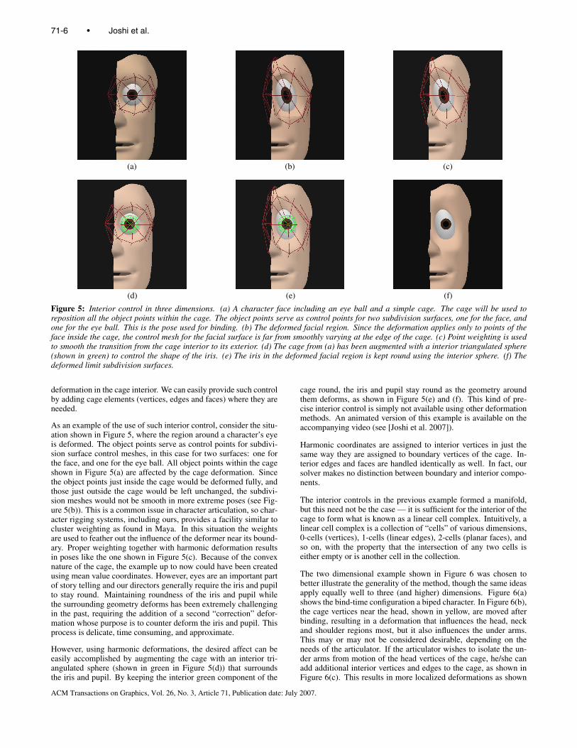
Figure 5: Interior control in three dimensions. (a) A character face including an eye ball and a simple cage. The cage will be used toreposition all the object points within the cage. The object points serve as control points for two subdivision surfaces, one for the face, andone for the eye ball. This is the pose used for binding. (b) The deformed facial region. Since the deformation applies only to points of theface inside the cage, the control mesh for the facial surface is far from smoothly varying at the edge of the cage. (c) Point weighting is usedto smooth the transition from the cage interior to its exterior. (d) The cage from (a) has been augmented with a interior triangulated sphere(shown in green) to control the shape of the iris. (e) The iris in the deformed facial region is kept round using the interior sphere. (f) Thedeformed limit subdivision surfaces.
deformation in the cage interior. We can easily provide such controlby adding cage elements (vertices, edges and faces) where they areneeded.
As an example of the use of such interior control, consider the situ-ation shown in Figure 5, where the region around a character’s eyeis deformed. The object points serve as control points for subdivi-sion surface control meshes, in this case for two surfaces: one forthe face, and one for the eye ball. All object points within the cageshown in Figure 5(a) are affected by the cage deformation. Sincethe object points just inside the cage would be deformed fully, andthose just outside the cage would be left unchanged, the subdivi-sion meshes would not be smooth in more extreme poses (see Fig-ure 5(b)). This is a common issue in character articulation, so char-acter rigging systems, including ours, provides a facility similar tocluster weighting as found in Maya. In this situation the weightsare used to feather out the influence of the deformer near its bound-ary. Proper weighting together with harmonic deformation resultsin poses like the one shown in Figure 5(c). Because of the convexnature of the cage, the example up to now could have been createdusing mean value coordinates. However, eyes are an important partof story telling and our directors generally require the iris and pupilto stay round. Maintaining roundness of the iris and pupil whilethe surrounding geometry deforms has been extremely challengingin the past, requiring the addition of a second “correction” defor-mation whose purpose is to counter deform the iris and pupil. Thisprocess is delicate, time consuming, and approximate.
However, using harmonic deformations, the desired affect can beeasily accomplished by augmenting the cage with an interior tri-angulated sphere (shown in green in Figure 5(d)) that surroundsthe iris and pupil. By keeping the interior green component of the
cage round, the iris and pupil stay round as the geometry aroundthem deforms, as shown in Figure 5(e) and (f). This kind of pre-cise interior control is simply not available using other deformationmethods. An animated version of this example is available on theaccompanying video (see [Joshi et al. 2007]).
Harmonic coordinates are assigned to interior vertices in just thesame way they are assigned to boundary vertices of the cage. In-terior edges and faces are handled identically as well. In fact, oursolver makes no distinction between boundary and interior compo-nents.
The interior controls in the previous example formed a manifold,but this need not be the case — it is sufficient for the interior of thecage to form what is known as a linear cell complex. Intuitively, alinear cell complex is a collection of “cells” of various dimensions,0-cells (vertices), 1-cells (linear edges), 2-cells (planar faces), andso on, with the property that the intersection of any two cells iseither empty or is another cell in the collection.
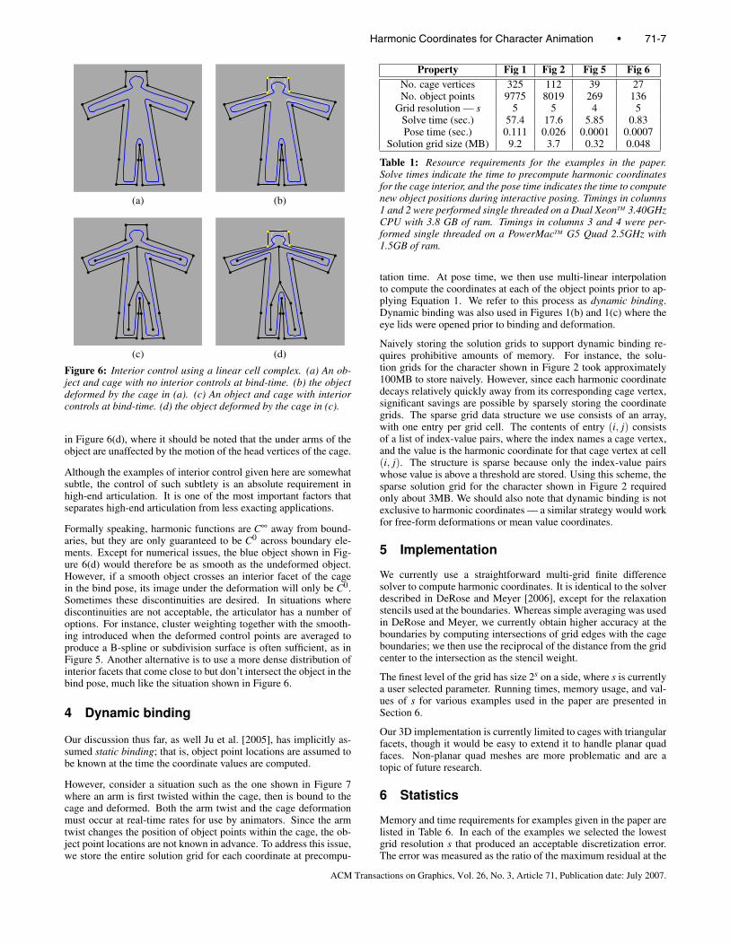
The two dimensional example shown in Figure 6 was chosen tobetter illustrate the generality of the method, though the same ideasapply equally well to three (and higher) dimensions. Figure 6(a)shows the bind-time configuration a biped character. In Figure 6(b),the cage vertices near the head, shown in yellow, are moved afterbinding, resulting in a deformation that influences the head, neckand shoulder regions most, but it also influences the under arms.This may or may not be considered desirable, depending on theneeds of the articulator. If the articulator wishes to isolate the un-der arms from motion of the head vertices of the cage, he/she canadd additional interior vertices and edges to the cage, as shown inFigure 6(c). This results in more localized deformations as shown
71-6 • Joshi et al.
ACM Transactions on Graphics, Vol. 26, No. 3, Article 71, Publication date: July 2007.
(a) (b)
(c) (d)
Figure 6: Interior control using a linear cell complex. (a) An ob-ject and cage with no interior controls at bind-time. (b) the objectdeformed by the cage in (a). (c) An object and cage with interiorcontrols at bind-time. (d) the object deformed by the cage in (c).
in Figure 6(d), where it should be noted that the under arms of theobject are unaffected by the motion of the head vertices of the cage.
Although the examples of interior control given here are somewhatsubtle, the control of such subtlety is an absolute requirement inhigh-end articulation. It is one of the most important factors thatseparates high-end articulation from less exacting applications.
Formally speaking, harmonic functions are C∞ away from bound-aries, but they are only guaranteed to be C0 across boundary ele-ments. Except for numerical issues, the blue object shown in Fig-ure 6(d) would therefore be as smooth as the undeformed object.However, if a smooth object crosses an interior facet of the cagein the bind pose, its image under the deformation will only be C0.Sometimes these discontinuities are desired. In situations wherediscontinuities are not acceptable, the articulator has a number ofoptions. For instance, cluster weighting together with the smooth-ing introduced when the deformed control points are averaged toproduce a B-spline or subdivision surface is often sufficient, as inFigure 5. Another alternative is to use a more dense distribution ofinterior facets that come close to but don’t intersect the object in thebind pose, much like the situation shown in Figure 6.
4 Dynamic binding
Our discussion thus far, as well Ju et al. [2005], has implicitly as-sumed static binding; that is, object point locations are assumed tobe known at the time the coordinate values are computed.
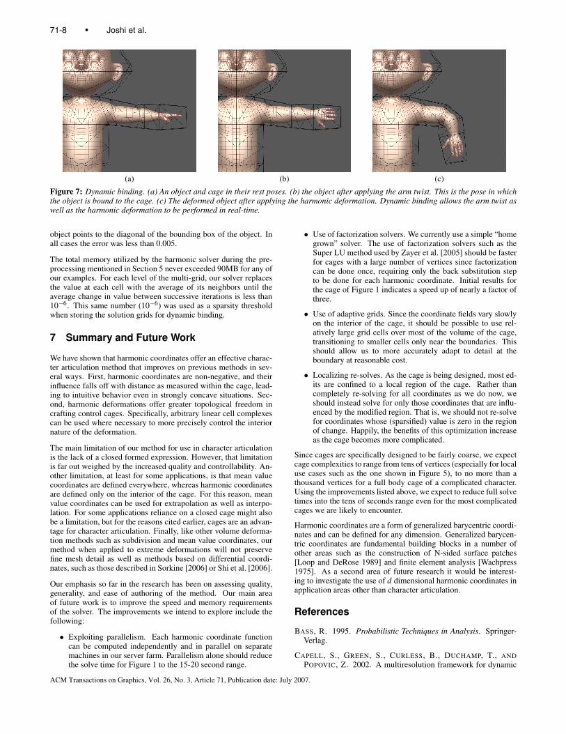
However, consider a situation such as the one shown in Figure 7where an arm is first twisted within the cage, then is bound to thecage and deformed. Both the arm twist and the cage deformationmust occur at real-time rates for use by animators. Since the armtwist changes the position of object points within the cage, the ob-ject point locations are not known in advance. To address this issue,we store the entire solution grid for each coordinate at precompu-
Property Fig 1 Fig 2 Fig 5 Fig 6No. cage vertices 325 112 39 27No. object points 9775 8019 269 136
Grid resolution — s 5 5 4 5Solve time (sec.) 57.4 17.6 5.85 0.83Pose time (sec.) 0.111 0.026 0.0001 0.0007
Solution grid size (MB) 9.2 3.7 0.32 0.048
Table 1: Resource requirements for the examples in the paper.Solve times indicate the time to precompute harmonic coordinatesfor the cage interior, and the pose time indicates the time to computenew object positions during interactive posing. Timings in columns1 and 2 were performed single threaded on a Dual XeonTM 3.40GHzCPU with 3.8 GB of ram. Timings in columns 3 and 4 were per-formed single threaded on a PowerMacTM G5 Quad 2.5GHz with1.5GB of ram.
tation time. At pose time, we then use multi-linear interpolationto compute the coordinates at each of the object points prior to ap-plying Equation 1. We refer to this process as dynamic binding.Dynamic binding was also used in Figures 1(b) and 1(c) where theeye lids were opened prior to binding and deformation.
Naively storing the solution grids to support dynamic binding re-quires prohibitive amounts of memory. For instance, the solu-tion grids for the character shown in Figure 2 took approximately100MB to store naively. However, since each harmonic coordinatedecays relatively quickly away from its corresponding cage vertex,significant savings are possible by sparsely storing the coordinategrids. The sparse grid data structure we use consists of an array,with one entry per grid cell. The contents of entry (i, j) consistsof a list of index-value pairs, where the index names a cage vertex,and the value is the harmonic coordinate for that cage vertex at cell(i, j). The structure is sparse because only the index-value pairswhose value is above a threshold are stored. Using this scheme, thesparse solution grid for the character shown in Figure 2 requiredonly about 3MB. We should also note that dynamic binding is notexclusive to harmonic coordinates — a similar strategy would workfor free-form deformations or mean value coordinates.
5 Implementation
We currently use a straightforward multi-grid finite differencesolver to compute harmonic coordinates. It is identical to the solverdescribed in DeRose and Meyer [2006], except for the relaxationstencils used at the boundaries. Whereas simple averaging was usedin DeRose and Meyer, we currently obtain higher accuracy at theboundaries by computing intersections of grid edges with the cageboundaries; we then use the reciprocal of the distance from the gridcenter to the intersection as the stencil weight.
The finest level of the grid has size 2s on a side, where s is currentlya user selected parameter. Running times, memory usage, and val-ues of s for various examples used in the paper are presented inSection 6.
Our 3D implementation is currently limited to cages with triangularfacets, though it would be easy to extend it to handle planar quadfaces. Non-planar quad meshes are more problematic and are atopic of future research.
6 Statistics
Memory and time requirements for examples given in the paper arelisted in Table 6. In each of the examples we selected the lowestgrid resolution s that produced an acceptable discretization error.The error was measured as the ratio of the maximum residual at the
Harmonic Coordinates for Character Animation • 71-7
ACM Transactions on Graphics, Vol. 26, No. 3, Article 71, Publication date: July 2007.
(a) (b) (c)
Figure 7: Dynamic binding. (a) An object and cage in their rest poses. (b) the object after applying the arm twist. This is the pose in whichthe object is bound to the cage. (c) The deformed object after applying the harmonic deformation. Dynamic binding allows the arm twist aswell as the harmonic deformation to be performed in real-time.
object points to the diagonal of the bounding box of the object. Inall cases the error was less than 0.005.
The total memory utilized by the harmonic solver during the pre-processing mentioned in Section 5 never exceeded 90MB for any ofour examples. For each level of the multi-grid, our solver replacesthe value at each cell with the average of its neighbors until theaverage change in value between successive iterations is less than10−6. This same number (10−6) was used as a sparsity thresholdwhen storing the solution grids for dynamic binding.
7 Summary and Future Work
We have shown that harmonic coordinates offer an effective charac-ter articulation method that improves on previous methods in sev-eral ways. First, harmonic coordinates are non-negative, and theirinfluence falls off with distance as measured within the cage, lead-ing to intuitive behavior even in strongly concave situations. Sec-ond, harmonic deformations offer greater topological freedom incrafting control cages. Specifically, arbitrary linear cell complexescan be used where necessary to more precisely control the interiornature of the deformation.
The main limitation of our method for use in character articulationis the lack of a closed formed expression. However, that limitationis far out weighed by the increased quality and controllability. An-other limitation, at least for some applications, is that mean valuecoordinates are defined everywhere, whereas harmonic coordinatesare defined only on the interior of the cage. For this reason, meanvalue coordinates can be used for extrapolation as well as interpo-lation. For some applications reliance on a closed cage might alsobe a limitation, but for the reasons cited earlier, cages are an advan-tage for character articulation. Finally, like other volume deforma-tion methods such as subdivision and mean value coordinates, ourmethod when applied to extreme deformations will not preservefine mesh detail as well as methods based on differential coordi-nates, such as those described in Sorkine [2006] or Shi et al. [2006].
Our emphasis so far in the research has been on assessing quality,generality, and ease of authoring of the method. Our main areaof future work is to improve the speed and memory requirementsof the solver. The improvements we intend to explore include thefollowing:
• Exploiting parallelism. Each harmonic coordinate functioncan be computed independently and in parallel on separatemachines in our server farm. Parallelism alone should reducethe solve time for Figure 1 to the 15-20 second range.
• Use of factorization solvers. We currently use a simple “homegrown” solver. The use of factorization solvers such as theSuper LU method used by Zayer et al. [2005] should be fasterfor cages with a large number of vertices since factorizationcan be done once, requiring only the back substitution stepto be done for each harmonic coordinate. Initial results forthe cage of Figure 1 indicates a speed up of nearly a factor ofthree.
• Use of adaptive grids. Since the coordinate fields vary slowlyon the interior of the cage, it should be possible to use rel-atively large grid cells over most of the volume of the cage,transitioning to smaller cells only near the boundaries. Thisshould allow us to more accurately adapt to detail at theboundary at reasonable cost.
• Localizing re-solves. As the cage is being designed, most ed-its are confined to a local region of the cage. Rather thancompletely re-solving for all coordinates as we do now, weshould instead solve for only those coordinates that are influ-enced by the modified region. That is, we should not re-solvefor coordinates whose (sparsified) value is zero in the regionof change. Happily, the benefits of this optimization increaseas the cage becomes more complicated.
Since cages are specifically designed to be fairly coarse, we expectcage complexities to range from tens of vertices (especially for localuse cases such as the one shown in Figure 5), to no more than athousand vertices for a full body cage of a complicated character.Using the improvements listed above, we expect to reduce full solvetimes into the tens of seconds range even for the most complicatedcages we are likely to encounter.
Harmonic coordinates are a form of generalized barycentric coordi-nates and can be defined for any dimension. Generalized barycen-tric coordinates are fundamental building blocks in a number ofother areas such as the construction of N-sided surface patches[Loop and DeRose 1989] and finite element analysis [Wachpress1975]. As a second area of future research it would be interest-ing to investigate the use of d dimensional harmonic coordinates inapplication areas other than character articulation.
References
BASS, R. 1995. Probabilistic Techniques in Analysis. Springer-Verlag.
CAPELL, S., GREEN, S., CURLESS, B., DUCHAMP, T., ANDPOPOVIC, Z. 2002. A multiresolution framework for dynamic
71-8 • Joshi et al.
ACM Transactions on Graphics, Vol. 26, No. 3, Article 71, Publication date: July 2007.
deformations. In ACM SIGGRAPH Symposium on ComputerAnimation, ACM SIGGRAPH, 41–48.
CARR, J. C., BEATSON, R. K., CHERRIE, J. B., MITCHELL,T. J., FRIGHT, W. R., MCCALLUM, B. C., AND EVANS, T. R.2001. Reconstruction and representation of 3D objects with ra-dial basis functions. In SIGGRAPH 2001, Computer GraphicsProceedings, ACM Press / ACM SIGGRAPH, E. Fiume, Ed.,67–76.
CHOE, B., LEE, H., AND KO, H.-S. 2001. Performance-drivenmuscle-based facial animation. The Journal of Visualization andComputer Animation 12, 2, 67–79.
DEROSE, T., AND MEYER, M. 2006. Harmonic co-ordinates. Pixar Technical Memo 06-02, Pixar Anima-tion Studios, January. http://graphics.pixar.com/HarmonicCoordinates/.
DUCHON, J. 1977. Splines minimizing rotation invariant semi-norms in sobolev spaces. In Lecture Notes in Mathematics,Springer-Verlag, vol. 571.
FLOATER, M. S., KOS, G., AND REIMERS, M. 2005. Mean valuecoordinates in 3d. Computer Aided Geometric Design 22, 623–631.
FLOATER, M. S., HORMANN, K., AND KOS, G. 2006. A generalconstruction of barycentric coordinates over convex polygons.Advances in Comp. Math. 24, 311–331.
FLOATER, M. 2003. Mean value coordinates. Computer AidedGeometric Design 20, 1, 19–27.
IGARASHI, T., MOSCOVICH, T., AND HUGHES, J. F. 2005. As-rigid-as-possible shape manipulation. In SIGGRAPH ’05: ACMSIGGRAPH 2005 Papers, ACM Press, New York, NY, USA,1134–1141.
JOSHI, P., TIEN, W. C., DESBRUN, M., AND PIGHIN, F. 2006.Learning controls for blend shape based realistic facial anima-tion. In SIGGRAPH ’06: ACM SIGGRAPH 2006 Courses, ACMPress, New York, NY, USA, 17.
JOSHI, P., MEYER, M., DEROSE, T., GREEN, B., ANDSANOCKI, T. 2007. Harmonic coordinates for char-acter articulation. Pixar Technical Memo 06-02b, PixarAnimation Studios. http://graphics.pixar.com/HarmonicCoordinatesB/.
JU, T., SCHAEFER, S., AND WARREN, J. 2005. Mean value coor-dinates for closed triangular meshes. ACM Trans. Graph. 24, 3,561–566.
LEWIS, J. P., CORDNER, M., AND FONG, N. 2000. Posespace deformation: a unified approach to shape interpolationand skeleton-driven deformation. In Proceedings of the 27thannual conference on Computer graphics and interactive tech-niques, 165–172.
LOOP, C. T., AND DEROSE, T. D. 1989. A multisided generaliza-tion of bezier surfaces. ACM Trans. Graph. 8, 3, 204–234.
MACCRACKEN, R., AND JOY, K. I. 1996. Free-form deformationswith lattices of arbitrary topology. In Proceedings of SIGGRAPH’96, Annual Conference Series, 181–199.
MEYER, M., LEE, H., BARR, A., AND DESBRUN, M. 2002. Gen-eralized barycentric coordinates for irregular polygons. Journalof Graphics Tools 7, 1, 13–22.
PINKHALL, U., AND POLTHIER, K. 1993. Computing discreteminimal surfaces and their conjugates. Experimental Mathemat-ics 2, 15–36.
PORT, S. C., AND STONE, C. J. 1978. Brownian Motion andClassical Potential Theory. Academic Press.
R.SIBSON. 1981. A brief description of natural neighbor interpo-lation. In Interpreting Multivariate Data, V. Barnett, Ed. JohnWiley, 21–36.
SEDERBERG, T. W., AND PARRY, S. R. 1986. Free-form deforma-tion of solid geometric models. In SIGGRAPH ’86: Proceedingsof the 13th annual conference on Computer graphics and inter-active techniques, ACM Press, New York, NY, USA, 151–160.
SHI, L., YU, Y., BELL, N., AND FENG, W.-W. 2006. A fast multi-grid algorithm for mesh deformation. In SIGGRAPH ’06: ACMSIGGRAPH 2006 Papers, ACM Press, New York, NY, USA,1108–1117.
SORKINE, O. 2006. State of the art report: Differential representa-tions for mesh processing. Computer Graphics Forum 25, 4.
SUMNER, R. W., ZWICKER, M., GOTSMAN, C., AND POPOVIC,J. 2005. Mesh-based inverse kinematics. ACM Trans. Graph.24, 3, 488–495.
WACHPRESS, E. 1975. A Rational Finite Element Basis. AcademicPress.
WAHBA, G. 1990. Spline models for observational data. InCBMS-NSF Regional Conference Series in Applied Mathemat-ics, SIAM, Philadelphia, PA, USA, vol. 59.
WARREN, J. 1996. Barycentric coordinates for convex polytopes.Advances in Computational Mathematics 6, 97–108.
ZAYER, R., ROSSL, C., KARNI, Z., AND SEIDEL, H.-P. 2005.Harmonic guidance for surface deformation. In The EuropeanAssociation for Computer Graphics 26th Annual Conference :EUROGRAPHICS 2005, Blackwell, Dublin, Ireland, M. Alexaand J. Marks, Eds., vol. 24 of Computer Graphics Forum, Euro-graphics, 601–609.
Harmonic Coordinates for Character Animation • 71-9
ACM Transactions on Graphics, Vol. 26, No. 3, Article 71, Publication date: July 2007.
