harmonica-inspired digital musical instrument design based on an
TRANSCRIPT

Harmonica-inspired digital musical instrumentdesign based on an existing gestural
performance repertoire
Julian VogelsMusic Technology Area
Schulich School of Music
McGill University, Montréal
November 2014
Input Devices and Music Interaction Laboratory
C I RM M T
Centre for Interdisciplinary Research
in Music Media and Technology
A thesis submitted to McGill University in partial fulfillment of the requirements for the degreeof Master of Arts.
© 2014 Julian Vogels
2014/11/29

i
Abstract
This thesis contributes to the field of electronic musical instrument (EMI) design, with astrong focus on harmonica-type gestural controllers. Harmonicas are arguably the best-selling instruments in the world, coupled with a huge community of musicians. Thus,it is surprising that little academic material about harmonica performance gestures andharmonica-related EMI design exists, as the Richter-tuned harmonica exhibits a unique setof musical techniques for sound modification.In spite the few academic works, several patents have been filed related to harmonica-related EMI design. These are presented and compared in a patent review. The devicesdisplay many common aspects that presumably stand in relation with different harmonicatypes. The application of the note-bending technique on the devices is especially investi-gated.In order to draw further conclusions about instrument interaction, a motion capture studyof harmonica performance gestures was carried out, including a qualitative evaluation oftwo harmonica-related EMIs.Finally, the findings are considered in an instrument augmentation prototype implemen-tation based on an existing harmonica-related digital musical instrument (DMI). A sensorsystem adapted to the playing technique is proposed, along with tailored mapping strate-gies.

ii
Résumé
Cette thèse contribue au domaine du design d’instruments de musique éléctronique (IME),plus précisement des contrôleurs gestuels liés à l’harmonica. On peut considérer que les har-monicas sont les instruments les plus vendus au monde, en lien avec une grande communautéde musiciens. Par conséquence, il est surprenant que aussi peu de matériel académique ex-iste sur les gestes de performance d’harmonica et sur le design d’IME lié à cet instrument, sion considère que l’harmonica diatonique simple présente un ensemble unique de techniquesmusicales pour la modification du son.Contrairement à la petite quantité de publications académiques, plusieurs brevets concer-nant les IME liés à l’harmonica ont été délivrés. Ceux-ci sont présentés et comparés dansun examen de brevets. Les dispositifs montrent beaucoup d’aspects en commun, ce quivraisemblablement est en rélation avec différent types d’harmonica. L’application de latechnique de l’altération des notes sur les dispositifs est étudiée plus en profondeur.Afin de tirer des conclusions sur l’interaction avec cet instrument, une étude de capture demouvement de performance d’harmonica a été réalisé, incluant une évaluation qualitativede deux IME liés à l’harmonica.Finalement, les résultats ont été considerés dans une mise en œuvre de prototype d’instrumentaugmenté, basé sur un instrument musical digital (IMD) lié à l’harmonica. Un système decapteurs ajustés à la technique de jeu est proposé, ainsi que des stratégies adaptées demappage.

iii
Acknowledgments
First of all, my thanks go to Marcelo M. Wanderley for the supervision of my thesis progress,and all my colleagues at the IDMIL for their advice and wisdom.I would also like to thank Pat Missin for pointing out additional harmonica-inspired ges-tural controller patents, Lei Chen and Ichiro Fujinaga for their help with the translationof Chinese and Japanese patents, Benjamin Bacon and Carolina Brum Medeiros for theirhelpful advice in setting up the motion capture hardware and during the analysis of thedata.As well, thank you to the excellent harmonica player Lévy Bourbonnais for his advice andpatience, as well as all the participants of the harmonica performance gestures study.
For their friendly ways of providing information about their inventions, I thank DavidWhalen and Michael DiCesare from My Music Machines, Inc., Rock Erickson (Millioniser2000 ), Wayne Read (XHarp), Vern Smith (Hands-Free Chromatic), and Ronald Schlimme(ECH ).
Thanks to my wonderful wife Cindy for enduring the madness of my graduate studiesand helping me through them. Finally, a special thanks to Cornelius Pöpel for passing onhis fascination for Music Technology to me, having inspired me to pursue this field in thefirst place.

iv
Contents
1 Introduction 11.1 Thesis overview . . . . . . . . . . . . . . . . . . . . . . . . . . . . . . . . . 21.2 Contributions . . . . . . . . . . . . . . . . . . . . . . . . . . . . . . . . . . 3
2 Harmonica Playing Techniques and Styles 42.1 Background . . . . . . . . . . . . . . . . . . . . . . . . . . . . . . . . . . . 4
2.1.1 Brief history of the harmonica . . . . . . . . . . . . . . . . . . . . . 42.1.2 Harmonica types . . . . . . . . . . . . . . . . . . . . . . . . . . . . 7
2.2 Playing techniques . . . . . . . . . . . . . . . . . . . . . . . . . . . . . . . 122.2.1 Holding the instrument . . . . . . . . . . . . . . . . . . . . . . . . . 132.2.2 Note selection techniques . . . . . . . . . . . . . . . . . . . . . . . . 132.2.3 Note bending . . . . . . . . . . . . . . . . . . . . . . . . . . . . . . 142.2.4 Overblow and overdraw . . . . . . . . . . . . . . . . . . . . . . . . 152.2.5 Vibrato . . . . . . . . . . . . . . . . . . . . . . . . . . . . . . . . . 162.2.6 Trills and double notes . . . . . . . . . . . . . . . . . . . . . . . . . 162.2.7 Hand cupping . . . . . . . . . . . . . . . . . . . . . . . . . . . . . . 17
2.3 Playing styles . . . . . . . . . . . . . . . . . . . . . . . . . . . . . . . . . . 172.4 Conclusion . . . . . . . . . . . . . . . . . . . . . . . . . . . . . . . . . . . . 18
3 Harmonica-related Digital Musical Instruments 193.1 Controller types . . . . . . . . . . . . . . . . . . . . . . . . . . . . . . . . . 223.2 Musical gestures . . . . . . . . . . . . . . . . . . . . . . . . . . . . . . . . . 23
3.2.1 Excitation gestures . . . . . . . . . . . . . . . . . . . . . . . . . . . 233.2.2 Selection gestures . . . . . . . . . . . . . . . . . . . . . . . . . . . . 303.2.3 Modification gestures . . . . . . . . . . . . . . . . . . . . . . . . . . 33

Contents v
3.3 Musical control level . . . . . . . . . . . . . . . . . . . . . . . . . . . . . . 433.4 Applicable techniques . . . . . . . . . . . . . . . . . . . . . . . . . . . . . . 44
3.4.1 Measuring the note bending gesture . . . . . . . . . . . . . . . . . . 453.5 Tunings . . . . . . . . . . . . . . . . . . . . . . . . . . . . . . . . . . . . . 493.6 Sound synthesis . . . . . . . . . . . . . . . . . . . . . . . . . . . . . . . . . 503.7 Feedback modalities . . . . . . . . . . . . . . . . . . . . . . . . . . . . . . 523.8 Distribution in space . . . . . . . . . . . . . . . . . . . . . . . . . . . . . . 543.9 Feature extrapolations . . . . . . . . . . . . . . . . . . . . . . . . . . . . . 553.10 Dimension Space . . . . . . . . . . . . . . . . . . . . . . . . . . . . . . . . 563.11 Geographical distribution . . . . . . . . . . . . . . . . . . . . . . . . . . . . 593.12 Availability . . . . . . . . . . . . . . . . . . . . . . . . . . . . . . . . . . . 593.13 Conclusion . . . . . . . . . . . . . . . . . . . . . . . . . . . . . . . . . . . . 60
4 Harmonica Performance Gesture Study 614.1 Participant recruiting and study organisation . . . . . . . . . . . . . . . . . 62
4.1.1 Marker placement . . . . . . . . . . . . . . . . . . . . . . . . . . . . 624.2 Course of the study . . . . . . . . . . . . . . . . . . . . . . . . . . . . . . . 63
4.2.1 Playing techniques . . . . . . . . . . . . . . . . . . . . . . . . . . . 644.2.2 Performance expressiveness and orientational pitch . . . . . . . . . 684.2.3 Free improvisation . . . . . . . . . . . . . . . . . . . . . . . . . . . 71
4.3 Conclusion . . . . . . . . . . . . . . . . . . . . . . . . . . . . . . . . . . . . 73
5 DMI Evaluation and Jamboxx Augmentation 745.1 Evaluation of harmonica-related DMIs . . . . . . . . . . . . . . . . . . . . 74
5.1.1 Jamboxx . . . . . . . . . . . . . . . . . . . . . . . . . . . . . . . . . 755.1.2 Millioniser 2000 . . . . . . . . . . . . . . . . . . . . . . . . . . . . . 78
5.2 Instrument Augmentation . . . . . . . . . . . . . . . . . . . . . . . . . . . 805.2.1 Sensor system design . . . . . . . . . . . . . . . . . . . . . . . . . . 815.2.2 Software design . . . . . . . . . . . . . . . . . . . . . . . . . . . . . 88
5.3 Conclusion . . . . . . . . . . . . . . . . . . . . . . . . . . . . . . . . . . . . 97
6 Conclusions and Future Work 986.1 Conclusion . . . . . . . . . . . . . . . . . . . . . . . . . . . . . . . . . . . . 986.2 Future Work . . . . . . . . . . . . . . . . . . . . . . . . . . . . . . . . . . . 100
Contents vi
6.2.1 Harmonica performance gesture study . . . . . . . . . . . . . . . . 1006.2.2 Jamboxx Augmentation . . . . . . . . . . . . . . . . . . . . . . . . 101
A Harmonica Performance Gesture Study appendices 102A.1 Technical setup . . . . . . . . . . . . . . . . . . . . . . . . . . . . . . . . . 102
A.1.1 Audio and Video capture . . . . . . . . . . . . . . . . . . . . . . . . 104A.1.2 Analog Input . . . . . . . . . . . . . . . . . . . . . . . . . . . . . . 105A.1.3 Syncing . . . . . . . . . . . . . . . . . . . . . . . . . . . . . . . . . 106A.1.4 Rigid bodies . . . . . . . . . . . . . . . . . . . . . . . . . . . . . . . 107A.1.5 Marker labelling . . . . . . . . . . . . . . . . . . . . . . . . . . . . . 108
A.2 Matlab code . . . . . . . . . . . . . . . . . . . . . . . . . . . . . . . . . . 109A.3 Questionnaire responses . . . . . . . . . . . . . . . . . . . . . . . . . . . . 110
B Jamboxx Augmentation appendices 111B.1 Arduino code . . . . . . . . . . . . . . . . . . . . . . . . . . . . . . . . . . 111B.2 Max patch . . . . . . . . . . . . . . . . . . . . . . . . . . . . . . . . . . . . 114

vii
List of Figures
2.1 A diagram of the Richter-Tuning on a C-key diatonic harmonica. . . . . . . . . 52.2 Richter-Tuning in the key of C shown on a circle of fifths. . . . . . . . . . . . . 52.3 An old graphic of the Hohner “Marine Band” harmonica. . . . . . . . . . . . . 62.4 A disassembled Hohner “Special 20 Marine Band”. . . . . . . . . . . . . . . . . 72.5 The Richter-tuned diatonic harmonica . . . . . . . . . . . . . . . . . . . . 82.6 The chromatic harmonica (angled and side view). . . . . . . . . . . . . . . . . 92.7 The bass harmonica. . . . . . . . . . . . . . . . . . . . . . . . . . . . . . . . 92.8 The chord harmonica. . . . . . . . . . . . . . . . . . . . . . . . . . . . . . . 102.9 The tremolo harmonica. . . . . . . . . . . . . . . . . . . . . . . . . . . . . . 102.10 The harmonetta. . . . . . . . . . . . . . . . . . . . . . . . . . . . . . . . . . 112.11 A diagram of the available bend notes on the Richter-tuned harmonica. . . . . . 142.12 A diagram of the available overblow and overdraw notes on the Richter-tuned
harmonica. . . . . . . . . . . . . . . . . . . . . . . . . . . . . . . . . . . . . 16
3.1 The mechanism to measure air pressure and note position as presented in Hillairet,
Lecadre, and Wallace (1970). . . . . . . . . . . . . . . . . . . . . . . . . . . . 243.2 A simplified schematic of the air channel profile as presented in Robert (1982). . 253.3 A simplified schematic of the air channel profile as presented in Arai (1984), em-
bodiment alternative 1. . . . . . . . . . . . . . . . . . . . . . . . . . . . . . . 253.4 A graphic of the air channel profile as presented in Matsuzaki (1986). . . . . . . 263.5 A graphic of the air channel profile as presented in Ziegler (1989). . . . . . . . . 273.6 Air channel sensor system designs involving strain gauges. . . . . . . . . . . . . 273.7 A graphic of the air channel profile as presented in Wheaton (1993). . . . . . . . 28
List of Figures viii
3.8 Schematic of a proposition of an air pressure measurement system across all air
channels (Arai 1984) . . . . . . . . . . . . . . . . . . . . . . . . . . . . . . . 293.9 The Millioniser 2000, a device presented in Blobel, Muller, and Studer (1983). 313.10 A schematic of the Jamboxx (Whalen, Luther, and DiCesare 2011). . . . . . . . 323.11 A top view schematic of the Electronic Harmonica. . . . . . . . . . . . . . . . 343.12 A top view schematic of the Millioniser 2000. . . . . . . . . . . . . . . . . . . 353.13 A top view schematic of the electronic harmonica by Arai (1984), first embodiment
alternative. . . . . . . . . . . . . . . . . . . . . . . . . . . . . . . . . . . . . 363.14 A top view schematic of the electronic harmonica by Arai (1984), second embodi-
ment alternative. . . . . . . . . . . . . . . . . . . . . . . . . . . . . . . . . . 373.15 A top view schematic of the Input Device for an Electronic Musical Instrument by
Matsuzaki (1986), first embodiment alternative. . . . . . . . . . . . . . . . . . 373.16 A top view schematic of the Input Device for an Electronic Musical Instrument by
Matsuzaki (1986), second embodiment alternative. . . . . . . . . . . . . . . . . 383.17 A schematic drawing showing the transpose function of the harmonica-related DMI
as presented in Ziegler (1989). . . . . . . . . . . . . . . . . . . . . . . . . . . 393.18 A schematic drawing showing the top side of the harmonica-related DMI as pre-
sented in Wheaton (1993). . . . . . . . . . . . . . . . . . . . . . . . . . . . . 393.19 A schematic drawing showing the top surface of the harmonica-related DMI as
presented in Read and Hebert (2013). . . . . . . . . . . . . . . . . . . . . . . 403.20 A schematic drawing showing the top surface of the Electronic Chromatic Har-
monica (ECH) as presented in Schille (1991). . . . . . . . . . . . . . . . . . . 423.21 A screenshot of the software provided together with the Jamboxx, a device pre-
sented in Whalen, Luther, and DiCesare (2011). . . . . . . . . . . . . . . . . . 533.22 A current version of the XHarp, a device presented in Read and Hebert (2013).
Photo courtesy of Wayne Read. . . . . . . . . . . . . . . . . . . . . . . . . . 553.23 Dimension Space representation based on a model adapted from Birnbaum et al.
(2005). . . . . . . . . . . . . . . . . . . . . . . . . . . . . . . . . . . . . . . 573.24 Dimension Space representations of various harmonica-related Digital Musical In-
struments based on a model adapted from Birnbaum et al. (2005). . . . . . . . 58
4.1 John is playing the modified harmonica, with markers attached to his hands and
wearing a marker head band. . . . . . . . . . . . . . . . . . . . . . . . . . . . 63
List of Figures ix
4.2 A graph displaying the cheek–chin distance and the estimate of fundamental fre-
quency during a hole 8 blow bend to E� and back. . . . . . . . . . . . . . . . . 654.3 A graph displaying the cheek–chin distance and the estimate of fundamental fre-
quency during a hole 3 draw bend to B� – A – A�. . . . . . . . . . . . . . . . . 654.4 A graph displaying the distance between the harmonica body centre versus the
spectral centroid during a performance of slow hand cupping (participant 1). . . 664.5 A graph displaying the distance between the harmonica body centre versus the
spectral centroid during a performance of slow hand cupping (participant 2). . . 674.6 A plot showing the hand cupping freqency of the participants when asked to per-
form as fast as possible. . . . . . . . . . . . . . . . . . . . . . . . . . . . . . 684.7 A boxplot showing the harmonica’s absolute orientational pitch angle across par-
ticipants as well as across performance expressivity, for a performance excerpt of
the piece “Summertime” by George Gershwin. . . . . . . . . . . . . . . . . . . 694.8 A boxplot showing the harmonica’s absolute orientational pitch angle across par-
ticipants as well as across performance expressivity, for a performance excerpt of
the piece “Room To Move” by John Mayall. . . . . . . . . . . . . . . . . . . . 704.9 An example frame of a video scrollplot used in the annotation of the improvisation
performance footage. . . . . . . . . . . . . . . . . . . . . . . . . . . . . . . . 714.10 A screenshot of the ELAN software used for the visualisation and partial annota-
tion of the video files. . . . . . . . . . . . . . . . . . . . . . . . . . . . . . . . 72
5.1 An overview of the prototype with annotated sensor system features. . . . . . . 815.2 Additional external electronics unit. . . . . . . . . . . . . . . . . . . . . . . 825.3 Pattern layout of the infrared emitter and photo transistor array. . . . . . . . . 865.4 A close-up view of the infrared emitter and photo transistor sensor array. . . . . 875.5 The Jamboxx Augmentation software, entirely made in Max. . . . . . . . . . . . 89
A.1 A diagram showing the camera setup in a bird’s-eye view perspective. . . . . . . 103A.2 The Oqus cameras are connected to the Qualisys Track Manager, which produces
a real-time 3D visualization of the motion capture. . . . . . . . . . . . . . . . . 104A.3 Left to right: DPA 4006-TL Stereo Microphone set, Sony PWM EX-3 professional
high definition video camera, Qualisys Oqus motion capture camera with high-
speed infrared video capture. . . . . . . . . . . . . . . . . . . . . . . . . . . . 105

List of Figures x
A.4 A hardware wiring diagram of the motion capture setup used for the harmonica
performance gesture study. . . . . . . . . . . . . . . . . . . . . . . . . . . . . 106A.5 The modified diatonic harmonica with markers mounted on an asymmetrical wooden
cross. This enables rigid body definition in the QTM. . . . . . . . . . . . . . . 108

xi
List of Tables
3.1 A comparison of the number of air channels depicted in the patent publications of
corresponding harmonica-related DMIs. . . . . . . . . . . . . . . . . . . . . . 333.2 Three-row key change button layout (Mölders 1980). . . . . . . . . . . . . . . . 353.3 A standard tuning as used for chromatic harmonicas. . . . . . . . . . . . . . . 493.4 A standard Richter tuning as used for diatonic harmonicas. . . . . . . . . . . . 503.5 A non-standard tuning based on a six note distance on the twelve tone row. . . . 50
A.1 Harmonica performance gesture study questionnaire responses (excerpt without
comments). . . . . . . . . . . . . . . . . . . . . . . . . . . . . . . . . . . . . 110

xii
List of Acronyms
ADC Analogue-to-digital converterCIRMMT Centre for Interdisciplinary Research in Music Media and TechnologyCSV Comma-separated valuesDMI Digital musical instrumentDOF Degrees of freedomEEPROM Electrically erasable programmable read-only memoryEMD Exponential moving deviationEMI Electronic musical instrumentFM Frequency modulationHID Human interface deviceIMD Instrument musical digitalIME Instrument musical éléctroniqueIMU Inertial measurement unitIR Infra-redMRI Magnetic resonance imagingOSC Open Sound ControlPCB Printed circuit boardPVC Polyvinyl chlorideQTM Qualisys Track ManagerR&B Rhythm and BluesSPI Serial peripheral interfaceStd Standard deviationTSV Tab-separated valuesVST Virtual Studio Technology

1
1 | Introduction
The harmonica is an instrument that has widely influenced popular music. It is portableand inexpensive, which makes it accessible to the low-income part of society, who in turnhave developed manifold playing techniques and styles. As an integral instrument to genressuch as Blues, Folk, and Country (Licht 1980), its sound has influenced many generationsof music lovers.
When compared to the vast amount of literature about other wind instruments, such asthe clarinet or the saxophone, the harmonica has received little attention in the academicrealm. There are many reasons for this, including its history as a rather cheap non-classicalinstrument played mostly by the poor, as well as its association with Blues music, a genrewhich represents an “antithesis of mainstream European classical tradition” (Baker 1999).How can we raise awareness of this unique instrument and connect harmonica music moreeasily with the electronic musical genres of the Twenty-First Century?
This thesis is devoted to the development of novel musical instruments based on the ratherunder-appreciated harmonica, which can facilitate finding new forms of musical expression.There have been many attempts to develop harmonica-related digital musical instruments(DMIs), but the majority of them did not meet with a big response. We suggest thatthe lack of acceptance of harmonica-related DMIs in the community of expert harmonicaplayers is at least partly due to inadequate design decisions with regards to the existingharmonica performance gestural repertoire.
The gestural repertoire of experienced harmonica players is rich and very personal. Thereare many techniques that can lead to a desired sound, some of which have been studied
2014/11/29
1 Introduction 2
more extensively only in the past two decades. Vocal tract forming techniques are espe-cially crucial to the unique sound of the diatonic harmonica. However, they are difficultto measure in a live performance context. We outline the current state of research on thistopic and present suggestions on how to translate these techniques to other body parts.Harmonica playing techniques should be studied as a starting point for every harmonica-related DMI development, and subsequently considered in the design process so as to meetthe harmonica players’ needs.
We believe that harmonica-related DMIs have a great potential regarding intuitiveness andmusical control. While preserving the dynamic playing possibilities of a wind controller,the note selection is not conveyed by the hands, as it would be on other wind controllerssimulating, for example, saxophone or trumpet interaction. This frees up bandwidth inorder to perform other musical tasks.Furthermore, harmonicas are known in many cultures. This small, familiar instrument iseasily picked up and played, even by those without a musical background.
The Manifesto for Music Technologists (Baym et al. 2014) calls out for a more open anddemocratized music technology of cultural awareness and interdisciplinary research. Withthe work done in this thesis, we hope not only to foster the belonging of the non-academicinstrument makers into the field of music technology, but also to improve collaboration andsharing.
1.1 Thesis overview
The remainder of this document is structured as follows: Chapter 2 provides the necessarycontext about the history and available types of acoustic harmonicas, and also explainscommon playing styles and techniques.Chapter 3 includes an extensive patent review of harmonica-related digital musical instru-ments, demonstrating different sensor system approaches and concepts of interaction.Chapter 4 describes a motion capture study that gives insight into the performance gesturesof expert harmonica performers.Chapter 5 deals with the practical design of a harmonica-related digital musical instrumentbased on a pre-existing commercially available device.
1 Introduction 3
Finally, Chapter 6 presents conclusions and points to future work that will be continuedafter the publication of this thesis.
1.2 Contributions
The study of harmonica playing gestures and their application to the design of a novelgestural controller yield a valuable contribution to the field of human computer interactionin music, as well as to interface design and musicology. The results will help us under-stand the design requirements of harmonica-inspired DMIs to suit the needs of experiencedharmonica players. Existing controllers are evaluated, which provides useful feedback tothe developers as well as insight towards the history of harmonica-related controllers formusicologists. We hope that, by pointing out and investigating important design decisions,developers of harmonica-related DMIs will be inspired to build devices that provide a moreintuitive interaction for expert harmonica players. These devices will therefore be morewidely accepted in the community of harmonica players.
4
2 | Harmonica Playing Techniquesand Styles
This chapter presents a brief history of the harmonica and describes common playing tech-niques and styles from a performance perspective.
2.1 Background
2.1.1 Brief history of the harmonica
The harmonica was invented in the beginning of the 19th century in Europe. It is a freereed aerophone instrument, which means that the sound is produced as air flows past areed that is firmly attached to one side of a closely fitting frame. The air flow causes thefree reed to oscillate within the frame, which in turn produces audible sound waves.
The circumstances of the introduction of free reed instruments to the western world arenot known with certainty. Some musicologists suggest that the Sheng, a Chinese free reedinstrument invented ca. 3000 years ago, was brought to Europe across Russia at the end ofthe 18th century, inspiring the development of other free reed instruments (Schwörer-Kohl1997; Krampert 1998). Other sources suggest that the development of reed instruments,mainly centred around the reed organ, led to the independent invention of free reed instru-ments, as elaborated in Ahrens (2002).Whatever the case, it is certain that by the year 1800, free reeds were known throughoutEurope. During the following decades, various free reed instruments were invented, untilaround 1820 when the first free reed harmonicas appeared in Austria. In 1824, the firstharmonica factory was founded in Vienna.
2014/11/29

2 Harmonica Playing Techniques and Styles 5
1
blowdraw
2 3 4 5 6 7 8 9 10
C E G C E G C E G CD G B D F A B D F A
Fig. 2.1 – A diagram of the Richter-Tuning on a C-key diatonic harmonica.
Around 1825 in Bohemia the Richter-Tuning system was invented, which is used totune the same hole blow and draw harmonicas until today. As we can see on the circle offifths in Fig. 2.2, Richter-Tuning is centred around the tonic chord (in the case of a C-keyharmonica, this would be the major triad C-E-G), where the blow notes repeat this patternthroughout the playing positions (cf. Fig. 2.1). The draw positions include notes foundin the respective dominant, dominant seventh, and parallel sub-dominant chords1. Thesub-dominant chord (here F-A-C) cannot be produced.Richter-Tuning can be seen as a compromise between melody and harmony, enabling theperformer to play both diatonic melodies, a full major scale (cf. Fig. 2.1, pos. 4-7), andchords, but limiting the set of available notes. The scheme in Fig. 2.2 can be applied toother harmonica keys by rotating it to another position on the circle of fifths.
majortriad
Subdominantnotes of theC-key Richter-Tuning
Dominant
dominant chord
subdominantparallel chord
Tonic
CG
D
A
E
BF
Fa
dB
E
A
D
G
g
e
b
f
c
ge
b
f
c
♯
♯
♯
♯
Fa
d
Fig. 2.2 – Richter-Tuning in the key of C shown on a circle of fifths.
1 Drawing air from the first or second three positions gives the dominant chord, positions 2-5 give thedominant seventh chord, and positions 4-6 give the sub-dominant parallel chord.

2 Harmonica Playing Techniques and Styles 6
From 1827, an instrument factory commenced mass production of the Richter-tuneddiatonic harmonica based on a design brought over from Vienna to Trossingen, Baden-Württemberg, in south-western Germany. Two years later, people also began mass pro-ducing harmonicas in the Bohemian and Saxon Vogtland, an instrument makers’ centreat that time. By 1839, there were already 50 small factories there, including C.A. SeydelSöhne, which is the most well-known nowadays (Meisel 1981).In Trossingen, the famous harmonica company Matth. Hohner began manufacturing har-monicas in the 1850’s. From 1862 onwards, Hohner harmonicas were exported to the USAwith huge success. One hundred and twenty years later, in 1986, Hohner passed the markof one billion harmonicas produced (HOHNER Musikinstrumente GmbH & Co, KG 2014).Berghoff (2001) traces the reasons for the remarkable product career of the Hohner har-monica.
Fig. 2.3 – An old graphic of the Hohner “Marine Band” harmonica. Repro-duced courtesy of the Deutsches Harmonikamuseum Trossingen.
With time, a plethora of harmonica variants were invented, including exotic exampleslike harmonica-zither hybrids (Brown 1899) and ring-shaped harmonicas (Anderson 1908).The most notable variants are described below in section 2.1.2 with diatonic and chromaticharmonicas being the most prevalent.
Common names for the harmonica include “harp”,“mouth organ”, “French harp”, “Mundhar-monika”, “pocket piano”, or “Mississippi saxophone” (Bahnson, Antaki, and Beery 1998).

2 Harmonica Playing Techniques and Styles 7
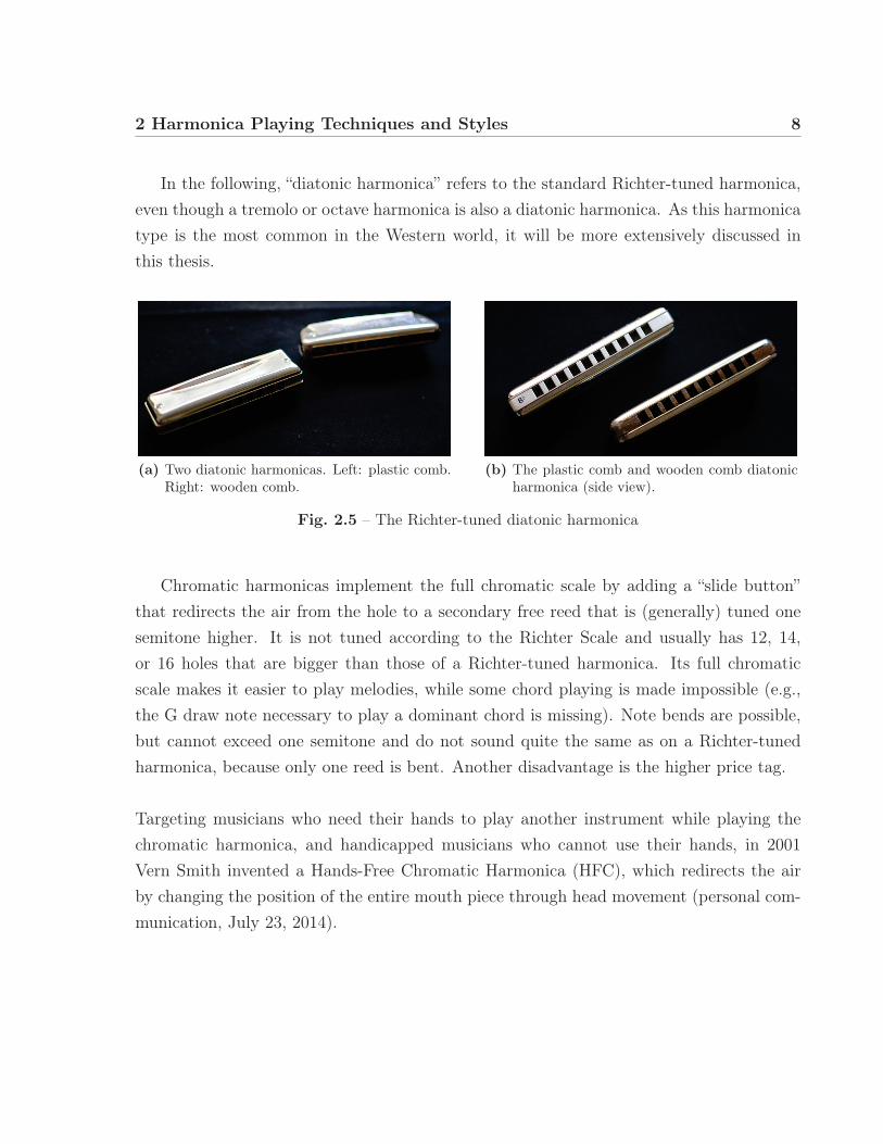
2.1.2 Harmonica types
Today, many different types of harmonicas exist. The most widely known and distributedharmonica is the Richter-tuned 10-hole diatonic harmonica. The ten holes are capable ofcovering three octaves, but only one full major scale can be found from holes four to seven.As seen in Fig. 2.5a and 2.5b, diatonic harmonicas are small enough to fit in a pocket.They can usually be easily disassembled to adjust or repair the reeds (cf. Fig. 2.4). TheRichter-tuned harmonica’s centre piece is either a plastic or wooden comb (cf. Fig. 2.5b),on which a metal plate holding the brass reeds is mounted on each side. The top andbottom caps protect the reeds and shape the sound.
Fig. 2.4 – A disassembled Hohner “Special 20 Marine Band” showing the topand bottom caps, the reed plates, and the plastic comb.
2 Harmonica Playing Techniques and Styles 8
In the following, “diatonic harmonica” refers to the standard Richter-tuned harmonica,even though a tremolo or octave harmonica is also a diatonic harmonica. As this harmonicatype is the most common in the Western world, it will be more extensively discussed inthis thesis.
(a) Two diatonic harmonicas. Left: plastic comb.Right: wooden comb.
(b) The plastic comb and wooden comb diatonicharmonica (side view).
Fig. 2.5 – The Richter-tuned diatonic harmonica
Chromatic harmonicas implement the full chromatic scale by adding a “slide button”that redirects the air from the hole to a secondary free reed that is (generally) tuned onesemitone higher. It is not tuned according to the Richter Scale and usually has 12, 14,or 16 holes that are bigger than those of a Richter-tuned harmonica. Its full chromaticscale makes it easier to play melodies, while some chord playing is made impossible (e.g.,the G draw note necessary to play a dominant chord is missing). Note bends are possible,but cannot exceed one semitone and do not sound quite the same as on a Richter-tunedharmonica, because only one reed is bent. Another disadvantage is the higher price tag.
Targeting musicians who need their hands to play another instrument while playing thechromatic harmonica, and handicapped musicians who cannot use their hands, in 2001Vern Smith invented a Hands-Free Chromatic Harmonica (HFC), which redirects the airby changing the position of the entire mouth piece through head movement (personal com-munication, July 23, 2014).

2 Harmonica Playing Techniques and Styles 9
Fig. 2.6 – The chromatic harmonica (angled and side view).
The bass or double bass harmonica is actually made up of two spatially-separatedharmonicas connected at the back by a hinge. The upper one is usually tuned in the scaleof C sharp, while the lower one is tuned in the scale of C. This way, by only using blownotes, the full chromatic scale is available. For a richer sound, two reeds per air channel aresometimes used. The width of a bass harmonica is about 30 centimetres. This instrumentis used mainly in harmonica ensembles.
Fig. 2.7 – The bass harmonica.
The chord harmonica is a very wide instrument capable of producing many differentchord types, such as major, minor, seventh, augmented, and diminished. Just like the bass

2 Harmonica Playing Techniques and Styles 10
harmonica, it is mainly used in ensembles and shows two rows of air channels, which arehowever clustered into groups of four. The major and seventh chords are usually arrangedon the upper row, whereas the minor, augmented, and diminished chords are arranged onthe lower row. The air channels produce a different chord, whether blown or drawn. Thewidth of a full-size chord harmonica is about 60-80 centimetres.Some chord harmonicas also have integrated bass reed air channels next to each set of chordchannels.
Fig. 2.8 – The chord harmonica.
Tremolo harmonicas have two reeds per air channel, which are slightly detuned: one isslightly flat and the other is slightly sharp. When both reeds are in oscillation, the detuningleads to a physical phenomenon called beating. As the frequencies are close, phase cancellingoccurs and results in a fluctuation of sound amplitudes perceived as a tremolo effect. Thefurther the reeds are detuned from each other, the faster the tremolo. Tremolo harmonicasusually have a note arrangement very similar to the Richter-tuned diatonic harmonica, butthe blow and draw holes are separate. They are very popular among South-East Asianharmonica players (Eyers 2011).
Fig. 2.9 – The tremolo harmonica.

2 Harmonica Playing Techniques and Styles 11
The aforementioned harmonica types are the most common, but there were many at-tempts to design interesting new harmonica-like devices. One of the most recognized deriva-tives of the harmonica is the Hohner Harmonetta (cf. Fig. 2.10). This device possessesa sophisticated mechanical mechanism for the redirection of air flow to the desired reeds.The honeycomb keyboard layout allows the player to choose chord combinations (Bibus1949; Mast 1953; Bibus 1958).
Fig. 2.10 – The harmonetta.
In the last few years, harmonica manufacturers have tried new radical designs, comingup with some interesting innovations in the field: The Hohner XB-40 is about 1.5 timesthe size of a standard diatonic harmonica, but comes with four reeds per hole separatedby a valve-like windsaver, which enables note bending on holes where it was once impos-

2 Harmonica Playing Techniques and Styles 12
sible. A somewhat similar functionality is provided by the Suzuki Sub 30, which adds onesympathetic reed to every air channel, keeping the dimensions of the standard diatonicharmonica.The Suzuki Overdrive harmonica has an airtight design for the cover plate, shielding one airchannel from another, so that every air channel has its own output air hole. By coveringthese holes with one finger, overblows and overdraws are achieved more easily (cf. sec.2.2.4).The B-Radical harmonica allows replacement of the reeds without having to throw awaythe whole instrument.
Many professional harmonica players have their harmonicas modified – “embossed” – toease the carrying out of note bending and overbending technique.
2.2 Playing techniques
The diatonic harmonica is a very expressive musical instrument, due to its intuitive designand manifold playing techniques and styles. For generations, harmonica performers haveused their imagination to find new ways of interacting with the instrument (Licht 1980).It is capable of producing sound when inhaling and exhaling into one of its ten airways.Tongue blocking or the pucking technique are used to select the input holes. The soundcan be altered by several vocal tract forming techniques, as well as breathing techniquesknown as note bending, overblowing, and overdrawing. By forming a cavity around theharmonica with the hands and altering their shape, a filter effect can be achieved.
There have been several studies on the physics of free reed instruments, including a fewspecific ones on the diatonic harmonica, which indicate gestures that are necessary to per-form on the acoustic harmonica (Johnston 1987; Bahnson, Antaki, and Beery 1998; Millot1999; Egbert et al. 2013). Steve Baker’s The Harp Handbook (Baker 1999) is consideredthe standard work on this instrument (Missin 2012; Baker 2014) in the community of har-monica players, and serves as a general reference to this chapter.
The described techniques and styles apply to the Richter-tuned diatonic harmonica.

2 Harmonica Playing Techniques and Styles 13
2.2.1 Holding the instrument
The Richter harmonica is usually held with the left hand so that the higher notes are onthe right side. The index finger lays on top of the instrument, while the thumb clamps itfrom the bottom. The harmonica touches the palm of the hand between these two fingers.The index finger is sufficiently far from the front edge of the harmonica to make way forthe lips, which form the embouchure.The other (right) hand wraps around the harmonica and the left hand in order to form acavity which impedes the free propagation of sound waves from cap openings. The innerside of the right hand thumb can be used to support the instrument and further enclosethe air in the cavity.
The vertical and horizontal angle at which the harmonica is held to the mouth influencesthe sound of the instrument.
2.2.2 Note selection techniques
Pucking and tongue blocking
Pucking technique is also referred to as “Puckering” and “Lipping”, and describes the useof a small embouchure similar to the one taken when whistling in order to direct the airflow to one hole at a time.Tongue Blocking techniques describe the use of a larger embouchure that directs the airflow to multiple holes at the same time, but where the tongue is used to block all the holesexcept one.
Pucking technique is usually acquired first in the learning process and its advantage isthat the tongue can be used for other purposes like sound alterations, staccato effects, oreasier control of note bending, as it is free to move in the mouth.The advantage of Tongue Blocking is the superior speed of note selection and the possibilityof additional rhythmic effects and sub-techniques such as octave playing and split intervals.

2 Harmonica Playing Techniques and Styles 14
Octave playing and split intervals
For octave playing, the tongue is used to block holes in the middle of the embouchure sothat the air flow is directed to the left and right side of the tongue, making it possible toplay octaves and other intervals.
A variation of the Tongue Blocking technique is the so-called U-blocking (Krampert 1998),where the tongue blocks two holes but lets air pass on either side and in the middle. Thistechnique enables the playing of additional chords.
2.2.3 Note bending
Note bending describes a technique involving altering the shape of the vocal tract whileplaying a note to lower its pitch. This technique enables playing chromatically on a diatonicharmonica, as well as sliding between certain notes.
Johnston (1987) states that it is only possible to bend a note if the other note in thesame hole has a lower pitch. Furthermore, he found that the amount which a note can bebent depends on the interval between the notes of the same hole: The pitch can descenddown to approximately one semitone above the lower-pitched note. A diagram of the avail-able bend notes on the Richter-tuned harmonica is shown in Fig. 2.11. For draw bends,the pitch can be altered gradually, whereas blow bends tend to change the pitch abruptly.
blow
hole
drawC E G C E G C E G CD G B D F A B D F AC F
F AG
AB
FF
DDB
A C E G
1 2 3 4 5 6 7 8 9 10
Fig. 2.11 – A diagram of the available bend notes on the Richter-tuned har-monica.

2 Harmonica Playing Techniques and Styles 15
Krampert (1998) stated that bending is achieved by “arching the tongue or the lips” toalter the direction of the air flow through the harmonica.What actually happens inside the air channel when bending a note is a primacy shift tothe lower-pitched reed, which is modulated up. Note bends therefore involve an upward,as well as a downward modulation of pitch. In comparison with the simple blow and drawtone, the bent tone appears to be almost a composite of the two (Bahnson, Antaki, andBeery 1998).
The necessary alteration of the vocal tract to bend a note depends on the frequency ofthe played note, and is greater if the note is bent down several semitones. An analogy usedto describe the alteration of the vocal tract is that of different unvocalised vowel sounds(Baker 1999).
Bends do not require increased air pressure and can be played at a minimal volume (Baker1999). Bahnson, Antaki, and Beery (1998) found that the level of pressure also has onlya slight influence on the phase relation of the reeds. Thus, varying pressure may onlymodulate the resulting amplitude, with no significant effect to the bent pitch.
2.2.4 Overblow and overdraw
Overblowing and overdrawing, also known as overbending technique, are rather recent play-ing techniques that emerged in the second half of the Twentieth Century. This techniquecan provide almost all the missing note pitches that cannot be achieved with either normalplaying or note bends.Even though the technique can be used theoretically on any hole, the overblows on holes 1,4, 5, 6 and overdraws on holes 7, 9, 10 are particularly interesting (Bahnson, Antaki, andBeery 1998). Examining the diagram in Fig 2.12, we can see that the achievable notes onholes 2 and 3 blow and 8 draw are either duplicates of the already available notes on theharmonica, or can be more easily achieved using note bending.

2 Harmonica Playing Techniques and Styles 16
blow
over-blow
over-draw
hole
drawC E G C E G C E G CD G B D F A B D F A
BFDCGD
C F G C
1 2 3 4 5 6 7 8 9 10
Fig. 2.12 – A diagram of the available overblow and overdraw notes on theRichter-tuned harmonica.
An overblow or overdraw is performed by “changing the position of the tongue and in-creasing the pressure of the upper lip, in a way similar to some techniques on the trumpet”.The technique requires a significant learning effort, with holes 4 through 6 being the easiestoverblow positions (Baker 1999).
The harmonica player that is most associated with overblowing and overdrawing techniqueis Howard Levy, who is considered a master of the technique.
2.2.5 Vibrato
Baker (1999) states three modes of vibrato: Throat vibrato, which is produced by thelarynx (or voice box), diaphragm vibrato, produced by tension-relaxation recurrences ofthe diaphragm, and hand vibrato, where the harp-holding hand shakes the instrumentdiagonally up and down.Baker mentions the importance of vibrato especially for harmonica performance: It smoothsout tiny variations in pitch that naturally occur because the correct intonation depends onthe shape of the player’s vocal tract to make the sound more pleasant.
2.2.6 Trills and double notes
The rapid alteration between two adjacent blow or draw notes is called a trill. Here, headand/or harp movement can be used to move the embouchure to the adjacent hole.

2 Harmonica Playing Techniques and Styles 17
Double notes describe the opening of the embouchure to direct part of the air flow to anadjacent hole in order to play a chord interval.
2.2.7 Hand cupping
The Hand Cupping technique consists of a modification of the cavity formed by the handsaround the harmonica. The timbre of the sound can be changed by altering the cavity,and effects like tremolo and wah-wah effects can be achieved. Tremolo can be controlledby a rapid flutter of the hand(s), while a wah-wah is achieved by opening the cavity whileplaying a note.
2.3 Playing styles
The Richter-tuned harmonica today is mainly used in Blues, Country, Rock, and Jazz mu-sic. It plays an especially important role in Blues music.
Blues music was developed by the black population of the USA in the late NineteenthCentury by mixing African vocal singing tradition with folk music of the European tradi-tion. The African singing tradition does not follow the same pitch scale to which Europeanears are accustomed, and involves many glissandi, which lead to the introduction of bluenotes in Blues music. These notes have a slightly lower pitch than the major scale andcannot easily be reproduced with fixed-pitch instruments like the piano.The possibility of performing note bends thus makes the diatonic harmonica a very suitableinstrument for Blues music, making it easy to perform slides between notes and blue notes.A characteristic sound achieved using the bending technique, especially in blues music, isthe hitting of an already bent-down note that is quickly brought up to its original pitch.
Licht (1980) argues that the use of ideophones and the embellishment of narratives withvocal mimicry in Afro-American folk tales lead to a specific style of harmonica performance,which similarly mimics sounds such as dog howls, train noises, car horns, etc. HarmonicaTrains – repeating rhythmic playing patterns – are an important part of harmonica bluesmusic.According to Glover (1965), blues playing styles are very personal and differ a great deal.He identifies artist Sonny Terry to be the general reference in the “folk blues” style, and

2 Harmonica Playing Techniques and Styles 18
Little Walter as having “set the style for R&B harp”, a more urban genre that appeared inthe 1940s. Other similarly important blues harp players include Sonny Boy Williamson Iand Sonny Boy Willamson II, whose styles are a mix of folk and country blues with R&B.There is also Jimmy Reed, who “blends both deep country and Chicago R&B” to make asound that was considered modern in 1965. Krampert (1998) adds to that list by mentioningthe revival of Blues Harmonica music in the 1980s, mainly due to the movie Blues Brothers.
Whereas the blues tonality exhibits both major and minor characteristics, Country mu-sic is generally more major and uses less heavy vibrato or wah wah effects (Baker 1999).As the harmonica is mainly a melody instrument, it can be integrated easily into Rock andits sub-genres as well.Jazz playing depends on the style of the piece, for which a good intonation is important anddifferent tonalities are employed. It is possible to play in many keys on any one harmonicaby using various positions.
The harmonica had some appearances in classical music as well, where the chromatic har-monica is used almost exclusively. Important classical harmonica soloists include LarryAdler, Tommy Reilly and John Sebastian, Sr. Composers of harmonica concertos includeHenry Cowell, Ralph Vaughan Williams, and Heitor Villa-Lobos (Krampert 1998).
2.4 Conclusion
In this chapter, necessary introductory information about the acoustic harmonica, its his-tory, and common harmonica types were presented. Playing techniques such as note bend-ing, overbending, and hand cupping were explained according to relevant literature.Playing styles, and especially the use of the harmonica in blues music was also described.

19
3 | Harmonica-relatedDigital Musical Instruments
With the technological development of the Western world in the second half of the Nine-teenth Century, the invention of new kinds of musical instruments was made possible. Earlyelectronic instruments include the Telharmonium, the Theremin, and the Ondes Marthenot.Later, analogue synthesizers became very popular, and the most widely used electronic mu-sical instrument up to now is still the keyboard synthesizer (Chadabe 2001).However, as Michel Pascal (1997) put it, “it is often not difficult to detect that a soundperfectly imitating a brass is in reality played from a keyboard”, and advocates for thenecessity of tailored electronic instruments for different groups of musicians.Expert harmonica players have excellent motor skills trained over many years of instrumentpractice. This existing gestural repertoire needs to be considered in the design of a novelelectronic musical instrument to account for some of the unique sound characteristics ofharmonica performance.
We employ the term “Harmonica-related Digital Musical Instruments” to describe a setof digital musical instruments designed to resemble the acoustic harmonica because of theways the musician uses to interact with it in a standard performance situation. These in-struments take advantage of the performance repertoire of experienced harmonica players,so that the musician can use his/her own existing knowledge and motor skills and applyit to the electronic instrument. Therefore, the learning curve is less steep, and a highermusical expression can be achieved in a smaller amount of time.Digital musical instruments (DMIs) are defined as musical instruments whose sound gen-eration is carried out by a computer and controlled by a gestural controller or control
2014/11/29
3 Harmonica-related Digital Musical Instruments 20
surface, where the physical interaction takes place (Wanderley and Depalle 2004; Mirandaand Wanderley 2006).
It is rare for a DMI to incorporate the rich interaction possibilities and feedback modalitiesof an acoustic counterpart. Most acoustic instruments have been developed and refinedover centuries, which is why they cannot be directly compared to DMI prototypes. Fur-thermore, a DMI is not generally developed to replace the acoustic counterpart, but ratherto add or extrapolate certain features, while others may become absent. This distinction isespecially important since many people have false expectations about the capabilities of aDMI, either thinking of it as a pure limitation or a toy, or expecting science fiction. Eventheir expectations of a DMI’s sound may be biased, perhaps since the advent of popularsynthpop music in the 1970s.
The diatonic harmonica is a perfect candidate for augmentation, as well as instrument-like or instrument-inspired design. The instrument has unique interaction characteristicsand playing techniques, but also many limitations that could be overcome with a DMIdesign. The diatonic harmonica is arguably the best-selling instrument in the world, whichindicates that there must be a great community of harmonica players who could possiblybe interested in a DMI design based on their instrument.
These reasons have already inspired the development of harmonica-related analogue elec-tronic instruments and later DMIs for over half a century. However, most existing devicesdo not make use of a fundamental part of the gestural repertoire, and provide interactiononly on the note-level. They overcome certain limitations of a diatonic harmonica, such aswear and tear of the reeds and the fixing to a particular key, but cannot reproduce the richinteraction to which the performers are accustomed.
Although the acoustic harmonica is a huge commercial success, harmonica-related elec-tronic instruments are not. None of the reviewed materials about the instruments havesuggested that they were sold to the mass market. Two recent developments failed in anattempt to crowd fund the production of the instrument (DiCesare 2012; Read 2012), andmany devices invented earlier are no longer produced.Since the acoustic harmonica is not a period instrument that is commonly found in an

3 Harmonica-related Digital Musical Instruments 21
orchestra, it is not a popular choice for performance studies in conservatories. It does notreceive much attention in the academic world either, when compared to the piano, theviolin, or the guitar. This is why it is not surprising that we could not find much academicwork on electronic harmonica-related instruments either.
In the following section, we will present a review of harmonica-related DMIs. Many differ-ent design decisions were made, such as mounting the blow hole on a slide versus havingmultiple blow holes, adding buttons to the instrument body, etc. With a better understand-ing of the interaction, we can adapt design principles, and thus significantly improve theacceptance of harmonica-like controllers in the community of harmonica expert performers.
The main sources of information were chosen to be patents, as they offer great insightto thoroughly developed ideas and ensure the originality of the presented device. As manydevelopers do not seem to work within an academic institution, but intend to invent acommercial product, patents prove to be a richer source than academic publications.
Patent review
We reviewed a total of 17 patents claiming harmonica-related electronic instruments orrelated inventions. The time span of these patents reaches from 1949, when Ernest RobertWorkman claimed the first design of an actual electronic harmonica, to 2013, when WayneRead claimed the invention of the XHarp. The dates refer to the issue of the patent.
The patents were investigated for information about the layout and use of different sensorson the device, descriptions of the musical gestures associated with it, as well as featureextrapolations and other design-relevant information.If additional information about the devices was found, e.g., in manuals or through personalcommunication with the developer, it has been indicated with a reference.Patent claims are often very broad and do not tell us anything about the actual manu-facturing of the device. It is not known how many of the harmonica-related DMIs wereactually produced commercially.
The depicted schemata were adapted from the patents.

3 Harmonica-related Digital Musical Instruments 22
3.1 Controller types
Digital musical instruments can be classified according to their resemblance with acousticinstruments. For example, just as a keyboard synthesizer tries to simulate a piano interac-tion as closely as possible, it can also be described as an instrument-like gestural controller.DMIs are generally classified into categories - “augmented musical instruments”, “instrument-like gestural controllers”, “instrument-inspired gestural controllers”, and “alternate gesturalcontrollers” (Miranda and Wanderley 2006). The latter does not have any resemblance toan existing acoustic instrument: The performance gestures need to be learned from scratch.All of the reviewed devices can be classified as instrument-like controllers. Some are bordercases between instrument-like and instrument-inspired design, as they introduce the needfor musical gestures which are not part of the acoustic harmonica gestural repertoire, whilepreserving elementary harmonica playing techniques.
Harmonica-related digital musical instruments must be distinguished from electric har-monicas. Electric instruments amplify the acoustic signal of the instrument, whereas digi-tal musical instruments produce computer-generated sound. Harmonica-related electronicinstruments do not have any reeds that could produce sound directly, but rely on a sen-sor acquisition system that measures the musician’s gestures. The input signals are thenmapped to the synthesized sound.
Augmented musical instruments are real acoustic musical instruments, which have beenmodified by adding sensors that capture originally uncaptured musical gestures or physicalproperties of the instruments. While leaving the original sound production of the instru-ment intact, computer-generated sound is either additionally produced, or the instrument’ssound is modified through a computer (Miranda and Wanderley 2006).Sometimes, however, the distinction between augmented and electric musical instrumentsis not easy to make. There are border cases where the only dimension measured is almostidentical to the resulting acoustic signal. One example would be the Turboharp developedby Antaki (2001), which implements an optical sensing technique to determine the vibrationfrequency of the reeds.

3 Harmonica-related Digital Musical Instruments 23
3.2 Musical gestures
3.2.1 Excitation gestures
An excitation gesture describes a gesture that is needed to generate the sound output of aDMI. It is the gesture, that “provides the energy that will eventually be present in the per-ceived phenomena” (Cadoz and Wanderley 2000). In the case of harmonica-related DMI,this is inherently blowing air into and/or drawing air out from one or more air channels.In terms of the sophistication of the excitation gesture measurement technique, it can bedifferentiated between mere triggering based on a threshold or physical interaction, andcontinuous measuring allowing for control over the amplitude envelope of the sound out-put.Seven patents were found to describe a device that is only capable of triggering a tone byestablishing an electrical contact in a tone generation circuit. Twelve patents described adevice capable of sensing air pressure continuously, so that the sensor signal can be usedto modulate the resulting tone and create an amplitude envelope.Two devices provided both a discrete note trigger by electrical contact, as well as a meansof measuring air pressure (Hillairet, Lecadre, and Wallace 1970; Mölders 1980).
Workman (1949) proposed the design of a device with five air channels, containing a flexiblemetal bar projection bent with the air flow of blowing into or drawing from the respectivehole of the instrument. This action brings it into electrical contact with a brush or termi-nal, establishing a closed circuit for sound production.In a second proposition, Workman employs a permanently magnetised metallic ball heldbetween two metallic tubes serving as contacts. Air pressure moves the ball to either oneside or the other, bringing it into electrical contact.
Wilken (1965) proposed a design containing an air channel with a double cone attached inthe centre by means of elastic rubber bands. The double cone, though not further specified,would move with the air flow in either the blowing or drawing direction, and be broughtinto contact with an electrical switch that turns on a tone generator.

3 Harmonica-related Digital Musical Instruments 24
Hillairet, Lecadre, and Wallace (1970) proposed a design, where a vertically-placedpiston is driven upwards to displace a leaf mounted on the air channel. This leaf establishesa contact with a hinged bar situated above the air channel and across all air channels.The bar acts as a resistor, which makes it possible to infer the position of the contactpoint by measuring the voltage across a voltage divider, similarly to the functionality of alinear potentiometer. The downside to this measurement technique is that only the nearestpiston contact of the hinged bar’s anode side will be measured, as the circuit is closedwith this contact. Any other contacts will not be recognized, which makes the instrumentmonophonic.
air flow
air flow
contact and displacement
single leaf
contact bar
(a) A graphic of the air channel profile.
lamp-shutter-photoresistorarrangement
contact bar single leaf
(b) A graphic of the mechanism used to measurebreath intensity.
Fig. 3.1 – The mechanism to measure air pressure and note position as presented in Hillairet,Lecadre, and Wallace (1970).
In order to give control not only over whether or not a tone is produced, but also overthe amplitude envelope of the tone, the contact bar is hinged and can be rotated. Aftercontact of the piston with the bar is established, the piston lifts up the bar, which resultsin rotational movement. A shutter plate displaying a transparent to opaque gradient ismounted at the hinge of the bar. A lamp and photo-resistor pair on either side of theshutter generate an analogue signal according to the transparency of the shutter plate. Asthe hinged bar is rotated, the shutter rotates along with it, swivelling the plate in front ofthe lamp and photo-resistor pair, and changing the resulting sensor signal.
French inventor Robert (1982) presented the Clavier Electromechanique à Vent ; a devicewhich enables the user to play an organ or piano by the use of a harmonica-like controller.The organ’s keys are struck by the means of electromagnets each turned on or off by a

3 Harmonica-related Digital Musical Instruments 25
mechanism in the controller’s air channels. Inside each air channel, a piston is held in aneutral position by two springs. As the piston is pierced at its centre, it can be displacedby applying either positive or negative air pressure, i.e., blowing and drawing respectively.The piston comes into physical contact with two metal leaves, which closes an electricalcircuit and turns on the electromagnet.
air flow
pistonspring
electricalcontact
electricalcontact
bypass hole
Fig. 3.2 – A simplified schematic of the air channel profile as presented inRobert (1982).
Arai (1984) propsed a design involving an elastic component that would be deformedwith the air pressure inside the air channel. The elastic component is attached to theleaf of an industry-standard contact switch. Given a certain deformation, the contact isinterrupted and a note onset is indicated. This solution improves the durability of thedevice by separating the electrical circuit from the air channel, protecting it from humidity.
air flow
elasticcomponent contact switch
air flow
Fig. 3.3 – A simplified schematic of the air channel profile as presented inArai (1984), embodiment alternative 1.

3 Harmonica-related Digital Musical Instruments 26
Kondo (1997) later proposed a similar measurement technique. It involves an elasticcomponent whose deformation does not actuate a switch, but is measured with a displace-ment measurement system.
Matsuzaki (1986) proposed an air channel sensor design involving an inclined elastic mem-ber with a magnet attached. The elastic member is bent by the force of the air flow,reducing the distance between the attached magnet and an electrical switch on the exteriorof the air channel.Matsuzaki (1986) is a development based on Arai (1984). Both inventions were affiliatedwith Casio Computer Co., Ltd. They both take advantage of elastic members to detect athreshold of air pressure. However, the original air channel layout of the acoustic harmon-ica cannot be maintained, as there is no way of including a mechanism for measuring bothpositive and negative air pressure in a single air channel. Therefore, both have proposedan air channel layout that introduces alternating blow and draw channels.
air flow
elasticmember magnet
contact switch
air flow
Fig. 3.4 – A graphic of the air channel profile as presented in Matsuzaki(1986).
Ziegler (1989) invented the Elektronische Mundaharmonika (EMH), which uses a dif-ferential air pressure sensor (0 to ±70 mBar) to measure the pressure that results fromthe air flow through the air channel. Differential air pressure sensors actually measure thedeformation of a diaphragm inside the sensor housing, which separates the air channel’s airfrom the surrounding atmosphere’s air. The pressure difference can therefore be positive or

3 Harmonica-related Digital Musical Instruments 27
negative, depending on the direction of the diaphragm’s displacement. As the back open-ing of the air channel is relatively small in size, positive pressure is built up when blownand negative pressure is built up when air is drawn. The measurement setup is capable ofdistinguishing between both directions of air flow and the amount of pressure applied.Similar to this air channel measurement setup, Whalen, Luther, and DiCesare (2011) andRead and Hebert (2013) have described their respective inventions Jamboxx and XHarp tomake use of a differential air pressure sensor.
air flow
differentialair pressure sensor
variable bypass of air
Fig. 3.5 – A graphic of the air channel profile as presented in Ziegler (1989).
Mölders (1980) proposed a Mundharmonika (ger.: mouth harmonica) that makes useof strain gauges to measure the air flow direction and pressure. A strain gauge is bond toa material strip in each air channel, which is bent in either direction when blowing into ordrawing air from the hole. Using a Wheatstone bridge circuit, the resistance change causedby the deformation of the gauge can be measured. The resistance decreases with compres-sion and increases with tension, so that both air flow directions can be distinguished. Theamount of resistance change is then mapped to the amplitude of the sound.Schille (1991) proposed an air channel sensing system design involving a strain gaugemounted perpendicular to the air stream inside the air channel. Similarly to the mea-suring technique used in Mölders (1980), the air stream bends the strain gauge in onedirection or the other, resulting in a resistance change that can be measured.
air flow
strain gauge
bypass hole
(a) A graphic of the air channel profileas presented in Mölders (1980).
air flow strain gauge
bypass hole
(b) A graphic of the air channel profile as presented in Schille(1991).
Fig. 3.6 – Air channel sensor system designs involving strain gauges.

3 Harmonica-related Digital Musical Instruments 28
Wheaton (1993) employs two solid state pressure sensors mounted on the top inner sideof the air channel, angled 45° to either direction of air flow. Solid-state pressure sensors donot have any moving parts, as a result of the application of piezo-resistive semiconductortechnology. As the two sensors are mounted triangularly in opposite directions, blowingand drawing can be distinguished while the intensity of the air stream can be determined.As an additional excitation gesture sensor, Wheaton uses a microphone to pick up singing,humming, or other sound input, although he does not specify where it is to be found onthe device.
air flow
solid stateair pressure sensor
Fig. 3.7 – A graphic of the air channel profile as presented in Wheaton (1993).
There exist several other sensors capable of measuring air pressure and flow direction,which could be considered in the air channel sensor system design. Da Silva, Wanderley,and Scavone (2005) outlines the pros and cons of hot wire sensors and pressure sensors suchas a Pitot tube for an application in the design of musical instruments.
3.2.1.1 Continuous control over signal amplitude
With respect to the control over the signal amplitude, two types of instrument interactionmeasurement could be determined:
1. Simplified control: The musician only has discrete control over note onset andoffset (cf. Matsuzaki (1986) in Fig. 3.4).
2. Complex control: The musician has discrete control over note onset and offset andcontinuous control over amplitude of the sound. This can be made possible by
• Sensor-enabled complex control: both note onset and control over ampli-tude are measured (cf. Hillairet, Lecadre, and Wallace (1970) in Fig. 3.1a)

3 Harmonica-related Digital Musical Instruments 29
• Hardware or software enabled mixed control: a pressure sensor signal isgated by setting a threshold value in hardware or software (cf. Millioniser byBlobel, Muller, and Studer (1983) in Fig. 3.9b)
Arai (1984) claimed one embodiment of the invention as having control over the amplitudeacross all air channels. Therefore, both blowing and drawing air channels are connectedand merged into a single airway (refer to Fig. 3.8). At its end, a pressure sensor is mountedin front of the opening to the atmospheric air.The pressure sensor consists of a magnet and a surrounding coil. The magnet inside thecoil is displaced with the air flow. This induces an electrical current into the coil, whichcan be measured, transformed, and mapped to the amplitude of the sound.This approach simplifies the design and lowers the production cost of the device. However,without a proper closing of the individual air channels, air can flow out of the other holes,diminishing the effect of the air pressure on the pressure sensor. Given the particular designby Arai (1984) with alternating blow and draw air channels, closing is probably difficult toachieve.
pressure sensor(magnet and coil)
air channels
(21)
Fig. 3.8 – Arai (1984) proposed air pressure measurements across all air chan-nels. The pressure sensor makes use of the electromotor force re-leased by magnet displacement inside a coil.
3.2.1.2 Air flow resistance
Many inventors considered the implementation of an air flow resistance. The acousticharmonica naturally provides a resistance to the air flow due to the inertia of the reedplates, so that the performer needs to make a certain effort to excite the system and producea sound. Excitation effort is useful in two ways: on the one hand, an excitation gesture canbe controlled more easily and the motor skills can be learned more quickly, but on the otherhand, excitation effort is seen by the audience and associated with musical expression. In“Effort and Expression”, Joel Ryan advocates for the consideration of excitation effort in

3 Harmonica-related Digital Musical Instruments 30
the creation of computer music: “Form as pure freedom is empty: it has no motive. Effortis consciousness of our struggles with the matter of music, music without matter can notsound.”(Ryan 1992)Ziegler (1989) introduced a system to limit the air flow manually by sliding a pierced barwhose holes can overlap the air channel openings, so that the hole diameter for each channelchanges, depending on the position of the bar.Blobel, Muller, and Studer (1983) described the air flow through the mouth piece of thedevice later called Millioniser 2000 as being screw-adjustable (see Fig. 3.9b on page 31).
3.2.2 Selection gestures
Selection gestures are gestures used to change a setting or mode, or a note that is to beplayed. For example, a selection gesture on a keyboard would be to choose another sound,e.g., a harpsichord sound preset. Pressing a keyboard key also inherits a selection gesture,because the finger moves to a position so as to select a certain note. Then, pressing thekey is an excitation gesture as well, as it produces sound output.The same occurs when an acoustic harmonica is played. The note is selected by movingthe mouth over to the corresponding air channel or channels and forming an embouchure.Then the air stream can be formed to excite the system and produce a sound.
3.2.2.1 Note selection
With harmonica-related DMIs, there are two types of devices with different approachesto the selection of notes. One approach is to provide a number of separate air channels,arranged just like those of an acoustic harmonica. The advantage of this is that harmonicaplayers intuitively recognize the function of the channels, and can also jump to anothernote just like on an acoustic harmonica.This is only true if the notes are accessible in the same way as on an acoustic harmon-ica. Several devices show an alternative note arrangement intrinsic to their design or thechosen tuning (cf. sec. 3.5 “Tunings”). If the air channel measurement setup is only ableto measure the air pressure in one direction of the air flow, blowing and drawing gesturescannot be applied to the same hole and the note arrangement needs to be changed. Arai(1984), Matsuzaki (1986), and Li and Li (1990) propose a note selection arrangement ofalternating blowing and drawing holes.

3 Harmonica-related Digital Musical Instruments 31
The other approach to note selection is to provide a mouth piece mounted on a slider.Sliding the mouth piece to a different position selects the note played when air is blowninto or drawn from the mouth piece. One advantage of this approach is the lower cost ofmanufacturing the device, as it only needs one air channel measurement system as opposedto multiple separate measuring systems. Another advantage is the fact that the number ofselectable notes can be chosen arbitrarily (if the slider’s sensing resolution is continuous).Thus, the device can emulate the note arrangement of, for example, a 10-hole diatonicharmonica as well as a 14-hole chromatic harmonica.The arbitrariness of the number of selectable notes can also be seen as a disadvantage tothis approach. The player has no visual, intuitive cue of where the notes are situated.Repeatability is an important key to the learnability of a DMI (Wanderley and Orio 2002).If the same gesture does not lead to the same resulting sound, the performer cannot adaptto the instrument or learn to play it. Therefore, one school of thought in DMI design ad-vocates for the use of more fixed mappings over very loose and often changing ones (Cook2001)1(Hunt and Wanderley 2002).
Furthermore, performers rely only on proprioception and ego-location, not on tactilecues, in order to slide to the desired note’s position.
(a) A photo of the Millioniser 2000, an example ofa slide-based harmonica-related DMI.
slideable mouth piece
differential pressure sensor
elastictube
adjustable bypassair channels
(b) A schematic of the slideable mouthpiece.
Fig. 3.9 – The Millioniser 2000, a device presented in Blobel, Muller, and Studer (1983).
Developers have put much thought into these shortcomings, and proposed differentsolutions. Blobel, Muller, and Studer (1983) employ a sliding mechanism allowing the1 NIME workshop during CHI 2001: http://www.nime.org/2001/

3 Harmonica-related Digital Musical Instruments 32
performer to feel bumps when sliding the mouth piece. The bumps are caused by equidistantnotches, which add friction to the sliding head. This direct tactile feedback may help withthe task of selecting the right note, but diminishes the advantage of an arbitrarily selectablenote number if the desired number of notes are not the least common denominator of thenumber of bumps.Whalen, Luther, and DiCesare (2011) accounted for this problem by employing a continuousslider, and attaching a replaceable strip of bumps right underneath the actual slider, sothat the bumps can be felt by the lower lip (Jamboxx Music 2014a). Several bump stripswith different spacings are provided with the instrument.
rotaryencoder
hinge
bump strip
slideable mouth piece
Fig. 3.10 – A schematic of the Jamboxx (Whalen, Luther, and DiCesare2011).
3.2.2.1.1 Number of air channels
As can be seen in Tab. 3.1, the number of air channels proposed in the various patentsvaries from 5 to 30 holes. The average number of air channels across all listed devices(except Jamboxx as it is variable) is exactly 15.25.
Comparing the number of air channels to those of acoustic harmonicas, we can see thatmost of the devices implement more channels than the Richter-tuned diatonic harmon-ica (10). Devices with 12, 14, or 16 air channels match the number of air channels foundon chromatic harmonicas.

3 Harmonica-related Digital Musical Instruments 33
Author Name No. of air
channels
Workman (1949) Musical Instrument 5
Wilken (1965) Mundorgel 10
Hillairet, Lecadre, and Wallace (1970) Electronic Harmonica 12
Mölders (1980) Mundharmonika 30
Robert (1982) Clavier Electromechanique à Vent 18
Blobel, Muller, and Studer (1983) Operating apparatus used at an electronic instrument provided with atleast one synthesizer / Millioniser 2000
16
Arai (1984) Electronic harmonica, as well as input device for here, embodiment 1 &2
17
Matsuzaki (1986) Input device for an electronic musical instrument, embodiment 1 11
Matsuzaki (1986) Input device for an electronic musical instrument, embodiment 2 17
Ziegler (1989) Elektronische Mundharmonika / EMH 14
Li and Li (1990) Multiple Tone Colour Changeable Tonal Modification Electronic Har-monica
24
Schille (1991) Electronic harmonica for controlling sound synthesizers / ElectronicChromatic Harmonica (ECH)
12
Wheaton (1993) Polyphonic breath-controlled electronic musical instrument 10
Zhang and Zhang (1993) Electronic mouth-organ 14
Kondo (1997) Harmonica Type Electronic Musical Instrument 10
Yongcai (1998) Electronic mouth organ 23
Whalen, Luther, and DiCesare (2011) Adaptive midi wind controller device / Jamboxx variable
Read and Hebert (2013) Multi Channel Digital Wind Instrument / XHarp 11
Table 3.1 – A comparison of the number of air channels depicted in the patentpublications of corresponding harmonica-related DMIs.
3.2.3 Modification gestures
Cadoz and Wanderley (2000) describe modification gestures as “being related to the modi-fication the instrument’s properties, without any substantial expense of energy being trans-ferred to the final sound”. They constitute a second expressive dimension, as they “affectthe relation between the excitation gesture and the sound”.
3.2.3.1 Structural modification
Structural modification gestures describe gestures to change a parameter affecting the over-all functionality of the device. The gestures are used in between or during performances,but rarely together with an excitation gesture.

3 Harmonica-related Digital Musical Instruments 34
Workman (1949) proposes a mechanism used to change the note arrangement of the de-vice by turning a knob on an auxiliary control unit. The knob is attached to a rotatabledrum with three surface areas occupying 120°each, of which the surface facing up has a setof mounted contacts making electrical contact with a set of brushes or terminals on theunit body. If the drum is turned, a different set of electrical contacts are made, effectivelychanging the tonality of the instrument to C major, G major, or D major.If the knob is pressed and displaced one step into the device, contacts with a second row setof terminals are made, adding sounders which produce tones one octave above the othersto provide “full concert tones”.
Hillairet, Lecadre, and Wallace (1970) describe the layout of various buttons and switches,as well as their functions. Fig. 3.11 shows this schematically.The switch 1 turns on the oscillator and is isolated from the other buttons and switches.One three-way switch 3 is used to select high, medium, or low octave transposition, andanother 9 controls register transposition or operation. A different switch 2 is used to de-termine whether both register and octave transposition will be applied.The switches 4 through 8 turn filters of a filter bank on or off, which determine the qualityof the output sound. The plate 10 is called the “vibrato control plate”. Buttons 11 and 12are arranged vertically on plate 10 and are used to sharpen or double sharpen the note.The position of buttons 11 and 12 correspond to the button on a chromatic harmonicaof the same function. This design enables immediate adaptation of experienced chromaticharmonica players.
4 5 6 7 89
10
1211
32
1
Fig. 3.11 – A top view schematic of the Electronic Harmonica, showing thelayout of the various buttons and switches (Hillairet, Lecadre, andWallace 1970).
Mölders (1980) proposes a layout of at least 14 buttons situated on the top of the de-

3 Harmonica-related Digital Musical Instruments 35
vice, arranged in several rows mirrored on the left and right side, so that they are easilyaccessible during performance. The keys carry out several functions, such as changing thekey and key mode, changing note arrangement to embody either a chromatic or diatonicsetup, and adding extra voices in octave transposition.The position of the buttons on the top side of the instrument and their function, alongwith the size and shape of the instrument, suggest that the developer was inspired by theHarmonetta, a variation of the acoustic harmonica providing a set of buttons to select chordvariations as well (cf. Fig. 2.10 in sec. 2.1.2).
C� G� D�
A� F CG D AE B F�
C� G�
Table 3.2 – Three-row key change button layout (Mölders 1980).
The Millioniser 2000, as depicted in Fig. 3.12, shows a fairly advanced arrangement ofbuttons, switches and slides. On the left, two rows of four buttons serve multiple functions.In program mode, the −8 and +8 buttons are designated to transpose the base key of theDMI down or up an octave, the −− and ++ buttons transpose it one whole tone, and the− and + buttons transpose it one semi-tone.
–S
function keys
volume control slider
mouth piece
filter control slider
slide levercontrol
half notelever
–8
––
–
+S
+8
++
+
6
4
2
0
7
5
3
1
Fig. 3.12 – A top view schematic of the Millioniser 2000, showing the layout ofthe various buttons and switches (Blobel, Muller, and Studer 1983).

3 Harmonica-related Digital Musical Instruments 36
In the centre of the top of the device, five programmable function keys are found. Theyserve as shortcuts so as to quickly select another sound preset during or between perfor-mances.
On the right, eight buttons (0-7) are laid out in a similar manner, but serve a differ-ent function. These buttons are used to navigate the settings of the separate synthesizerunit, e.g., to select a sound preset or assign it to a function key.The volume can be controlled using either the volume control slider or a knob on the syn-thesizer unit. On the latter device, there is another knob used to fine-tune the pitch as well(Millioniser 1984).
Arai (1984) proposed two alternative embodiments of the same invention. The first em-bodiment describes a harmonica-related DMI with set of keys laid out in a classic pianostyle on its top surface. Other than that, a variety of switches and sliders are used tochoose a pre-set sound, change the volume, set a key, and change usage mode to keyboardor harmonica mode.
12
2 3 4 5 N/A 6
1
2
airflow
Fig. 3.13 – A top view schematic of the electronic harmonica by Arai (1984), first embodimentalternative. 1 on/off power switch 2 integrated piezo loud speakers 3 sound selection4 volume control 5 key set switch 6 utilisation switch (harmonica or keyboard mode)12 touch keys.
In a second embodiment, the classic piano key layout is absent, probably to make roomfor a solar cell panel. Referring to Figure 3.14, two switches 5 are used to select a chordmode, whereas the set of switches 7 are used to select the base key. Different sound presets

3 Harmonica-related Digital Musical Instruments 37
can be chosen from the switch set 3, and effects like tremolo can be added by using theswitch set 8.
2 2
89
557
1
3
airflow
Fig. 3.14 – A top view schematic of the electronic harmonica by Arai (1984), second embodimentalternative. 1 on/off power switch 2 integrated piezo loud speakers 3 sound selection5 chord mode switch 7 chord tonic keytone selector 8 effect switches (e.g., tremolo)9 solar cell panel.
Matsuzaki (1986) presented two invention embodiments that partly build upon the workpresented in Arai (1984). In the first embodiment, he presented a device consisting of ablowing and drawing input device cabled to another physically separated device, whichcontains several buttons and a piano button layout.
2 10
6
Fig. 3.15 – A top view schematic of the Input Device for an Electronic Musical Instrument byMatsuzaki (1986), first embodiment alternative. 2 integrated piezo loud speakers 6utilisation switch (harmonica or keyboard mode) 10 tone color switch section.

3 Harmonica-related Digital Musical Instruments 38
A second embodiment (Matsuzaki 1986) describes a harmonica-type DMI on which akeyboard interface is situated on the top surface. He includes an almost completely identi-cal schematic drawing as Arai (cf. Fig. 3.8 and Fig. 3.16). However, the mapping strategyis not the same. Matsuzaki (1986) reversed the direction of the blow and draw holes andchanged the position of the volume control. He does not employ a “sound selection switchsection”, but a “tone color switch section” and labels the three switches 11 in Fig. 3.16 asgenerally “mode switch section”.
POWER
2
airflow
cf.Arai
(1984)
4 10
12
11
1
2
Fig. 3.16 – A top view schematic of the Input Device for an Electronic Musical Instrument byMatsuzaki (1986), second embodiment alternative. 1 on/off power switch 2 integratedpiezo loud speakers 4 volume section 10 tone color switch section 11 mode switchsection 12 touch keys. Note the inversion of air channels when compared to Fig. 3.13.
Ziegler (1989) described a function of his Elektronische Mundharmonika (EMH) astransposing the harmonica base key during or in between performances. The leftmost andrightmost air channels are not used for excitation gestures, but serve as a sensor for aselection gesture.By blowing a short air blast into the hole, the entire note arrangement is transposed eitherupwards or downwards. These air channels do not have a bypass opening for air to passthrough, so air pressure quickly builds up in the channel when blown and enhances thegesture recognition. They also have a greater spacing from the adjacent air channels, so asto avoid being accidentally mistaken for sound generating air channels.

3 Harmonica-related Digital Musical Instruments 39
air channelsstep function
down transposestep functionup
Fig. 3.17 – A schematic drawing showing the transpose function of theharmonica-related DMI as presented in Ziegler (1989).
Schille (1991) claimed the invention of the Electronic Chromatic Harmonica. As de-picted in Fig. 3.20, at least two push buttons are situated on the top left of the device andcan incorporate several functions not further described that concern the sound synthesizer,such as selecting another sound or adding chords.
Wheaton (1993) proposed a design as depicted in Fig. 3.18 also showing push buttonson the top left of the device. The six buttons have several functions, depending on themapping chosen on a control unit worn on the belt. Their function is not exactly specifiedin the patent, but they might be used to change to a different note arrangement mapping,which could be customized. Furthermore, they could enable or disable the aforementionedmicrophone or “one or more of the tone control transducers” (Wheaton 1993, col. 3), andperform several pitch and tone modification functions. Depending on mapping, the rever-beration, timbre, chord effects, etc. may be controlled with these buttons as well.
Finger pressure transducer (FSR)
Thumb wheel (bottom)
Lip pressure transducer (FSR, top and bottom)
push buttons 1 – 6
Fig. 3.18 – A schematic drawing showing the top side of the harmonica-related DMI as presented in Wheaton (1993).

3 Harmonica-related Digital Musical Instruments 40
Kondo (1997) filed a patent affiliated with Sony Corporation containing a harmonica-related DMI. On its top surface, a selection wheel with discrete steps for sound selection isfound, as well as two push buttons for tuning and timbre selection.Whalen, Luther, and DiCesare (2011) also claim a design showing two push buttons on thetop surface of the device. Their function is software-configured and may be used to selectdifferent instruments or scales. The current implementation of the DMI has two 1/8 inchjacks, which can be used to connect accessories such as foot or thumb switches (JamboxxMusic 2014b). Software is provided in order to use the accessory signal to switch virtualinstruments.
The XHarp invented by Read and Hebert (2013) has a LCD display on the top surfaceshowing a menu structure, which can be navigated by the use of a turning knob that ac-tuates a discrete-step rotary encoder. To select a feature, the knob is pressed down. Thatway, different sounds, as well as the key and transposition can be accessed. On the back ofthe device, another turning knob drives a rotary potentiometer to adjust the overall volumeof the sound output.
LCD display
rotarypotentiometer
joystickrotaryencoder
Fig. 3.19 – A schematic drawing showing the top surface of the harmonica-related DMI as presented in Read and Hebert (2013).

3 Harmonica-related Digital Musical Instruments 41
3.2.3.2 Parametric modification
Parametric modification gestures describe gestures used to continuously sculpt the soundwhile it is being produced, such as adding effects or changing various sound parameterslike amplitude (e.g., tremolo), pitch (e.g., vibrato), or timbre.
The gestural controller described in Workman (1949) involves a spring-loaded “resistanceelement” partly hidden inside the instrument, which can be displaced further into the in-strument with the fingers of the right hand. This action changes the contact point of avariable resistor with a closed electrical circuit, limiting the current, and thus the intensityof the produced tone.Due to the spring-load, rapid successive interruptions audible as a tremolo effect can beachieved, as well as slow resistance changes that affect the sound amplitude in a more subtleway.
The harmonica-related digital musical instrument described in Hillairet, Lecadre, and Wal-lace (1970) shows a movable plate on the right side of the device, which has an indentationto fit a right-hand finger. Frontal displacement of the right hand then moves the plate,which actuates an inductance sensor. The sensor signal is then mapped to the amplitudeof the sound output, so that a manual vibrato effect can be achieved.Referring to Fig. 3.11, there are two buttons 11 and 12 mounted vertically on the movingplate. Pressing one button sharpens the played note, whereas pressing both buttons at thesame time double sharpens the note.
The Millioniser invented by Blobel, Muller, and Studer (1983) as depicted on Fig. 3.12contains a half-note lever found on the right side of the device, where the sharpening switchon a chromatic harmonica would normally be found. The lever also has the exact samefunction and raises the note up one semitone. Next to the half-tone lever, a slide controllever is mounted to the tap of a linear piston-type potentiometer for continuous control ofvibrato or glissando, depending on the chosen mapping.A upward or downward octave glissando or portamento can be achieved by pressing theS+ or S− button, combined with a full inward movement of the slide lever.On the sloping top back surface of the device, two sliders actuating linear potentiometers

3 Harmonica-related Digital Musical Instruments 42
are located. The left one is used to adjust the overall amplitude of the sound output, andthe right one is called the “filter control slide”, which is used to “modify the sound whileplaying” (Millioniser 1984, p. 8).When the instrument is in “monophonic playing mode”, the left set of buttons on the topof the device consisting of −8, +8, −−, ++, −, + can be used in combination for thetransposition of a note. When the instrument is in “chord mode”, a fingering scheme canbe applied to these buttons in order to transform the played noted into a major, minor,augmented, or diminished chord. Using the half-tone lever, it is therefore possible to playevery chord within five blowing and drawing positions (Millioniser 1984, p. 20).The Millioniser has a docking connection for accessory controllers on the right side of thecontroller device. In the Millioniser Manual 1984, a trumpet accessory is described brieflyas having three trumpet valve-like transducers.
The Elektronische Mundharmonika patent describes a “Chromat”-Button. The name indi-cates its use as a sharpening button similar to that used for acoustic chromatic harmonicas.
/ switch
on / off switch infrared light sensor
push buttons
Fig. 3.20 – A schematic drawing showing the top surface of the ElectronicChromatic Harmonica (ECH) as presented in Schille (1991).
Referring to the Electronic Chromatic Harmonica by Schille (1991) as depicted inFig. 3.20, there are two ways to alter the output sound through modification gestures.The � / � switch is situated on the right side of the device, where the sharp switch on anacoustic chromatic harmonica would normally be found. This switch transposes the playednote one semitone up if partially pressed, and one semitone down if fully pressed.On the right back side of the device, an infrared light source and a photo diode can befound, which measure the amount of infrared light reflected from the performer’s hand.

3 Harmonica-related Digital Musical Instruments 43
As this is roughly related to the distance of the hand from the sensor, it can be used topartially measure the hand cupping gesture. The sensor signal is used to control a tremoloor vibrato effect.The attempt to measure the hand cupping gesture was an innovation in the field ofharmonica-related DMI development. Up to now, it remains the only design that could befound implementing such a sensor.Wheaton’s design includes several innovations to the field as well. He introduced force-sensing resistors to measure both finger pressure on the top of the device and lip pressureon the top and bottom of the device (cf. Fig. 3.18). As the mapping is user-definable withthe use of a control unit, no fixed mapping approach is described in the patent. However,Wheaton suggests the resulting sensor signals from the lip pressure to be mapped to pitchbend. The finger pressure signal could drive reverberation or other audio effects, timbremodification, or chord effects. On the bottom right side of the device, a thumb wheel canbe used to gradually change the amplitude of the sound, also depending on the chosenmapping (Wheaton 1993).
The Jamboxx has a step-less rotary encoder on its left side. For hand use, a turningknob is attached to the encoder and can be manipulated with the left hand while playing.If mounted on a stand, the device can be tilted up or down by head movement.The encoder’s sensor signal is mapped to pitch bend by default, but this mapping canbe changed software-wise. In order to be able to set the default, non-tilted position, theencoder can be calibrated using software. In a newer implementation of the DMI, a mass-spring system is used to return the instrument to the initial tilting position (Jamboxx Music2014a).
The XHarp has a joystick mounted on its top surface (cf. Fig. 3.19), which allows theperformer to quickly change from pre-saved menu choices, bend the pitch up or down, oradd effects such as tremolo, vibrato, and distortion.
3.3 Musical control level
Digital musical instruments can enable different degrees of musical control. For example,a classic sequencer would only provide control over the structure of the music, but not the

3 Harmonica-related Digital Musical Instruments 44
pitch or timbral content of the sound. Other devices only allow for control on the note-level,while others enable the performer to shape the timbre of the output sound.
All of the reviewed DMI patents were found to enable musical control on the note-levelat least. As harmonica-related DMIs, they naturally emulate the harmonica air channelsor measure the mouth position otherwise in order to select a pitched note. Pitch bend andvibrato or tremolo effects are seen here as note-level interaction as well.
Although several devices can be used to switch to another sound preset or adjust filterschanging the timbre of the sound, only the Polyphonic breath-controlled electronic musicalinstrument (Wheaton 1993) explicitly states coherent real-time control over the timbralquality of the sound.The Millioniser (Blobel, Muller, and Studer 1983) also has a continuous filter control slideon the top back of the device to change the quality of the sound, but it is not easy to reachduring performance due to the dimensions of the instrument (cf. Fig. 3.9a and 3.12).
3.4 Applicable techniques
In order for the tongue blocking technique (cf. sec. 2.2.2) to be recognized correctly by theinstrument, it needs to be polyphonic as well as supply multiple air channels. Furthermore,the technique needs to be adapted, or it might not be feasible if the note arrangementis changed, e.g. to an alternating blow and draw channel layout such as in Matsuzaki(1986). Examples of DMIs enabling tongue blocking technique are the devices presentedin Robert (1982), Matsuzaki (1986, both embodiments), Ziegler (1989), Schille (1991),Wheaton (1993), and Read and Hebert (2013).
The hand cupping technique (cf. sec. 2.2.7) is a fairly complex interaction between themusician and the instrument, since the shape of the palm and fingers, as well as their dis-tance from the harmonica’s body, influence the output sound. In order to emulate the samedegree of interaction, the shape and distance would need to be measured continuously, anda mapping strategy would be necessary in order to correspond to the behaviour of the HandCupping Technique as applied to an acoustic harmonica.

3 Harmonica-related Digital Musical Instruments 45
Schille (1991) proposed the only harmonica-related DMI design which considers the tech-nique. On the back of the device, an infrared sensor measures the amount of reflectedinfrared light (cf. sec. 3.2.3).
The overblow / overdraw technique is not supported by any of the reviewed devices.
3.4.1 Measuring the note bending gesture
A very distinct and unique feature of diatonic harmonica performance is the note bendingtechnique (cf. sec. 2.2.3), enabled by the particular design of mounting two reeds of anair channel facing in opposite directions (Bahnson, Antaki, and Beery 1998). This resultsin a complex physical interaction of the reeds when the resonance of the acoustic systemconsisting of the harmonica body and the shaped vocal tract changes, thus changing itsimpedance. This interaction is difficult to measure in a live performance setting, and wastherefore never directly used as a control value in any known harmonica-related DMI de-sign. On the contrary, engineers tried to translate the bending gesture so that it couldbe conveyed by other body parts (e.g., lips or fingers). We must then ask ourselves if anyof these translations have proven to be useful and easily adaptable for expert harmonicaplayers.
Bahnson, Antaki, and Beery (1998) used precision non-contacting proximity sensors2 tomeasure the reed displacement at a sampling frequency of 10 kHz. A volume-adjustableresonating chamber (a syringe) was placed into the air stream adjacent to the harp, simi-larly to the resonating chamber experiment setup in Johnston (1987). Adjusting the volumeof the syringe, which acts as a rudimentary equivalent to the vocal passage, simulated thealteration of the vocal tract during a note bend.Both vibration measurements and observations from a stroboscopic light video indicatedthat note bends involve an upward as well as a downward modulation of pitch.The results contradict the intuitive prediction that the nominal position of both reeds ofa hole should move outward on blowing with positive pressure in the air channel, and in-wards on drawing with negative pressure in the air channel. Also against intuition, thereeds vibrate in parallel motion for all holes except the high blow notes.2 Kaman Instruments KD-2400 (sensor acts as the resonating coil for the oscillator on a traditional Colpritts
oscillator circuit)

3 Harmonica-related Digital Musical Instruments 46
3.4.1.1 Measuring the shape of the vocal tract
The vibration of free reeds in an acoustic harmonica is coupled acoustically to a complexresonator: the human vocal tract. This acoustic system can be described in terms of itsimpedance. The impedance is the response of a particular passive system to harmonic exci-tation (Dalmont 2001). Applying this to the harmonica, one can say that the vibrating freereeds excite the system, including the vocal tract. Thus the impedance of the vocal tractinfluences the resulting sound. In acoustics, the specific impedance is a ratio of the pressureand the particle velocity at a specific given point. For a resonator, such as the vocal tractin the case for harmonicas, it is sufficient to describe the input impedance, which can becalculated by knowing the volume velocities and the pressure on each side (Dalmont 2001).In practice, this means that a microphone would have to be placed inside the performer’smouth during performance. This is, of course, very obtrusive and impractical. Thus, non-invasive methods of acoustic impedance measurements are needed, which renders the taskmore difficult.Epps, Smith, and Wolfe (1997) described a non-invasive method for the measurement ofvocal tract resonances. The method involves a loudspeaker attached to an impedance-matching horn, emitting a known signal (such as a sine sweep or white noise) to excite theacoustic system, and a pressure sensor to measure the response.Kob and Neuschaefer-Rube (2002) refined this method by measuring the response with theuse of both a pressure sensor and a velocity sensor. The methods are developed for mea-surements of speech resonances, but may be applied partly to the field of digital musicalinstruments. However, due to the use of audible excitation of the system, the methodscannot be applied directly in a live performance context.
Naumann (1979) proposed the design of an electronic musical instrument not directly re-lated to features of the acoustic harmonica, but illustrating a possible solution to the issueof measuring the shape of the vocal tract in a real-time performance environment. A sonicor ultrasonic receiver and transmitter pair is connected to a frequency-to-analogue voltagetransducer and amplifier, setting up an audio feedback in the oral cavity. The frequencyof the feedback system changes with the size of the vocal tract. Naumann also employs anoptical reflectance sensor to measure the distance between the tongue and the mouthpiece.

3 Harmonica-related Digital Musical Instruments 47
By knowing the size of the vocal tract and the position of the tongue, one can eventu-ally estimate the shape of the vocal tract. This dimension can be used to control pitchbend and other audio features that are characteristic to a note bend on an acoustic har-monica. Experienced harmonica players would then be able to make use of their existingknowledge of the note bending technique in order to perform pitch bends on a DMI.In order to map these measurements to coherent audio features, we need to know moreabout the correlation between the shape of the vocal tract and the resulting sound.Antaki et al. (2002) reviews experiments involving laryngoscopy (fibre optics videos), ul-trasonography (ultrasound scans), and fluoroscopy (X-ray scans) to gain knowledge aboutthe embouchure, tongue position, and oral cavity volume while performing different playingtechniques. Famous harmonica performer Howard Levy served as a subject in most of theexperiments, of which several videos are presented on a website (Antaki 2014).
Egbert et al. (2013) investigated this relationship with a different method: the vocal tractwas scanned using a magnetic resonance imaging (MRI) scanner during the performance ofa hole 3 draw note bend for both tongue blocking and pucking technique (cf. sec. 2.2.2),as well as for a hole 8 blow bend. Therefore, a special non-magnetizable harmonica had tobe used.The MRI images show the tongue position for normal playing position, a semitone bend, awhole note bend, and a minor third bend. The change of the vocal tract shape is describedas follows:
When playing the 3 hole draw bent notes, the body of the tongue elevates andhumps up toward the hard palate. As the bend deepens, the tongue retracts andthe apex of the elevation shifts more and more back toward the pharynx. Thisprocess creates a progressively larger cavity in the anterior part of the mouthbetween the elevated body of the tongue and the lips [...]. Simultaneously, thewidth of the pharynx decreases.
The position of the tongue while note bending is very similar for both tongue blocking andpucking technique. The difference is obviously that the tongue is touching the harmonicaon the left of the embouchure, which also results in a more asymmetrical shape.

3 Harmonica-related Digital Musical Instruments 48
Concerning the hole 8 blow bend, the investigators stated the following:
In the bent note, the body of the tongue is elevated toward the palate and thetongue is very far forward next to the lips and harmonica. The anterior surfaceof the tongue opposes the palate except in the center, leaving a small centralchannel just as in the 3 hole draw notes. The anterior oral cavity is small. Theupward and forward movement of the tongue is more extreme than that foundin the images of the 3 hole draw notes, and the pharynx is correspondinglywider.
According to the findings, the movement of the tongue differs for different playing positionson the harmonica. Thus, it may be possible to determine which hole is being played basedon measurements of the vocal tract size and shape.
3.4.1.2 Translating the note bending gesture
Existing harmonica-related DMIs translate the note bending gesture to another part of thebody, rather than trying to solve the vocal tract measurement issue.
The Millioniser has a lever control that can be used to bend the note. The hand dis-placement and force applied to a spring-loaded lever controls the pitch bend upwards ordownwards, depending on a secondary button interaction on the top left surface of thedevice.Wheaton (1993) proposed translating the note bending gesture to either lip pressure, fingerpressure, or thumb displacement.The Jamboxx has an option to use the rotary encoder wheel on the left side of the devicefor pitch bend. If the Jamboxx is held in the hands, the left hand and/or finger movementis used to turn the wheel. If the device is mounted on a stand, head inclination and lipdisplacement influence the inclination of the device, and thus the position of the rotaryencoder.Read and Hebert (2013) proposed a joystick placed on the top right surface of the device,which may be used to pitch bend a note. Thus, displacement of the right hand and/orfingers controls the bend.

3 Harmonica-related Digital Musical Instruments 49
3.5 Tunings
Only certain patents provide information about the suggested fixed tuning or dynamictunings of the instrument. Hillairet, Lecadre, and Wallace (1970), Robert (1982), andBlobel, Muller, and Studer (1983) proposed a tuning identical to that of the chromaticharmonica, as seen in Tab. 3.3. Ziegler (1989) suggests this very tuning, but shifted sothat it starts on G blow and A draw.All of the above-stated devices also provide a way to sharpen all notes by the actuation of abutton or switch. Thus, it can be inferred that the developers intend to mimic a chromaticharmonica interaction.
blow C E G C C E G C C E G Cdraw D F A B D F A B D F A B
Table 3.3 – A standard tuning as used for chromatic harmonicas. Proposedtuning for devices by Hillairet, Lecadre, and Wallace (1970),Robert (1982) and Blobel, Muller, and Studer (1983)
The device shown in Kondo (1997) is Richter-tuned (like a diatonic harmonica, cf. Fig.2.11 and Tab. 3.4). Wheaton (1993) is Richter-tuned as well, except the draw note onposition 2, which is an F instead of a G. However, this is not a fixed tuning, as the deviceoffers a way of reassigning the note values.Similarly, the Jamboxx provides a variety of assignable tunings, including user definablepresets. The factory defined presets include standard Richter tuning, a major, Blues3,Jazz4, and “Spanish” (Phrygian dominant scale)5 scale with same notes for blowing anddrawing, and a so-called “Super Harmonica”6 scale.The above devices all employ some continuous measurement of a modification gesture,whether in the form of a thumb wheel, force sensing resistors, or a rotary encoder. Thisindicates the importance of continuous and subtle control over the sound and its pitch,suggesting that the developers intended to mimic a diatonic harmonica interaction.3 e.g., C–D�–F–F�–G–A�–C4 e.g., C–D–E–G–A–C5 e.g., C–C�–E–F–G–G�–A�–C6 e.g., blow: A�–F–F–F–A–C–F–F, draw: C–E–G–A�–D–E–G

3 Harmonica-related Digital Musical Instruments 50
blow C E G C E G C E G Cdraw D G B D F A B D F A
Table 3.4 – A standard Richter tuning as used for diatonic harmonicas. Pro-posed tuning for devices by Kondo (1997), and Wheaton (1993)(in variation).
Mölders (1980) proposed an alternate tuning of the device (Tab. 3.5). Every blow anddraw note from the same hole has a pitch distance of six notes from the twelve tone row toeach other. On the circle of fifths, the notes lie on opposing sides.
blow F A E G D� D F� C� C G� B A�
draw B D� A� C� A G� C G F� D F E
Table 3.5 – A non-standard tuning based on a six note distance on the twelvetone row. Proposed tuning for a device by Mölders (1980).
3.6 Sound synthesis
Most of the patents only describe the actual device and not the sound synthesis algorithms.Usually, the sound synthesis is described as being interchangeable and not fixed.
Generally speaking, if the sound output of the device is meant to resemble the acous-tic harmonica’s sound, a physical modelling approach could be taken into consideration.Physical Modelling is a sound synthesis method that computes the sound output accordingto a mathematical model simulating the physical characteristics of a given sound source,i.e., a musical instrument such as the harmonica. Significant work has been done in thisactive field of research.
The development of physical modelling algorithms for a harmonica-like sound is basedon what we know about the physical properties of free reed instruments and acoustics.As early as 1830, German physicist Wilhelm Weber described a correct theory involvingthe influence of a compliant structure (such as the reed) on the input impedance of an aircolumn. Henri Bouasse later refined this theory, and many more followed. These studies,however, were more concerned with the beating reeds of woodwinds such as the clarinet,rather than free reeds (Benade 2012, p. 435).

3 Harmonica-related Digital Musical Instruments 51
Since the past two or three decades, the acoustics of free-reed instruments have been stud-ied with increased interest, cf. Cottingham (2011). In 1987, Robert Johnston publishedan article describing the note-bending technique, and presented results showing how theinstrument behaves when blown mechanically through an apparatus simulating the vocaltract with a syringe-like volume-adjustable air column (Johnston 1987). Bahnson, An-taki, and Beery (1998) investigated the harmonica free reeds’ vibration during normal playand note bends using both videoscopic analysis as well as a high precision proximity sensor.
A well-known French researcher on free reeds, Laurent Millot used strain gauges and adifferential pressure sensor to show the reed displacement and the internal overpressure indetail. The movement of the reeds during normal play, a draw bend, and an overdraw areshown, and quantitatively confirmed to be strictly sinusoidal. Millot was able to derivethe mass, stiffness, damping, quality factor, plucked eigen frequency, and rest offset of thetested reeds – an important step in the development of a complete model of the diatonicharmonica (Millot, Cuesta, and Valette 2001).Millot and Baumann (2007) proposed a Minimal Model of Free Reeds which reviews andbuilds upon previously proposed models and theories of free reeds (Debut and Millot 2001;Tarnopolsky, Fletcher, and Lai 2000), including one model of the Asian free-reed instru-ment sho (Hikichi, Osaka, and Itakura 2003). The model takes into account the entire airescape area between the reed and the plate (Useful Section), as well as the reed thickness.In addition, Millot (2011) proposes a vocal tract model to account for note bending.
Cottingham (2013) explains the torsional, transverse, and lateral vibration modes of a(Western-type) free reed and their respective effect on the time and nature of the attack ofthe resulting sound. Cottingham has conveyed substantial research in the field of free reedinstruments, especially on the American reed organ and Asian free-reed driven instruments.
An example of a (freely available) physical modelling virtual synthesizer VST is the MolokoHarmoniac. It uses audio input to feed an envelope follower, giving subtle control over thesound amplitude. Several controls can be used to modify the virtual reed’s reactivity to airpressure, as well as the size and resonance of the virtual instrument body coupled to thereed.

3 Harmonica-related Digital Musical Instruments 52
An alternative to the physical modelling approach is the much simpler FM synthesis. Thefamous Yamaha DX7 FM synthesizer introduced in 1983 already had a harmonica presetsound installed, which was supposedly used in the Tina Turner song “What‘s love got todo with it”. However, this example is pretty far from an accurate harmonica sound.
A harmonica sound could also be produced using a sampler and modified through filteringtechniques and digital audio effects.
3.7 Feedback modalities
Many acoustic musical instruments produce sounds which can directly induce vibrationsto the instrument’s body and can be felt by the performer. This can give additional infor-mation about the state of the instrument.DMIs constitute a separation between gestural controller and sound synthesis. As controldoes not need to take place in the same physical space as sound production, DMIs do notautomatically provide this type of haptic feedback.
Vertegaal, Ungvary, and Kieslinger (1996) proposed three types of artificial feedback thata DMI can produce: visual, tactile, and kinaesthetic. Here, visual feedback would be moreimportant at the learning stage, and kinaesthetic feedback would be more important atthe expert stage. Feedback can also be distinguished by being primary and secondary.Primary feedback describes the aforementioned types of feedback, whereas secondary feed-back describes the sound produced by the instrument itself (Wanderley and Depalle 2004).Feedback can be called passive if it is provided “through physical characteristics of thesystem”, and active if it is actively produced by the system in response to a user action.
Most of the reviewed DMIs do not provide active feedback, and none of them provideactive tactile or kinaesthetic feedback. However, some devices do provide active visualfeedback with the use of light-emitting diodes or screens.The DMI presented in Wheaton (1993) provides visual feedback on a separate unit, whichcan be worn on a belt. The feedback provided is thus not intended to give real-time in-formation while performing, but rather convey semantic information about the selectedconfigurations and modes of the instrument.

3 Harmonica-related Digital Musical Instruments 53
The Millioniser provides a similar visual display for giving feedback about selection ges-tures, situated on a separate synthesizer unit. Additionally, an LED array on this sameunit gives active visual feedback showing which note is selected. Given that the Millioniseris a slide-based harmonica-related DMI, this visual feedback helps the performer in thelearning process of finding the right slide position to select the desired note.Another slide-based harmonica-related DMI is the Jamboxx. Fig. 3.21 shows a screenshotof the software provided together with the instrument. According to the slide position, aposition indicator slides over a set of icons representing playing position, highlighting thecurrently selected note and hole. If the user blows into the mouthpiece, the selected iconturns yellow. The color intensifies with higher blowing pressure. For drawing, the iconturns blue and a minus is attached to the hole number. The position of the rotary encoderwheel on the left side of the device (cf. Fig.3.10) is indicated as a horizontal bar on topof the selected hole icon and on a graphic of a pitch bend wheel as found on keyboardinstruments.
Fig. 3.21 – A screenshot of the software provided together with the Jamboxx,a device presented in Whalen, Luther, and DiCesare (2011).

3 Harmonica-related Digital Musical Instruments 54
The XHarp supplies active visual feedback for selection gestures with an LCD screenmounted on the top surface of the device. The screen displays a menu structure, e.g. toselect a different sound.
The Jamboxx also serves as an example for passive force feedback: In a current embod-iment, the wheel on the left side of the device is spring-loaded to return to the initialposition. Therefore, the counter-force to that which needs to be applied on the wheel toachieve a certain effect gives information about the state of the instrument. In a similarmanner, the slide lever of the Millioniser provides passive feedback.
Comments from the participants of the harmonica performance gesture study presentedin section 5.1 suggest that expert performers are not aware of using tactile feedback duringperformances and think that they do not need to rely on it.
3.8 Distribution in space
Digital Musical Instruments can be classified according to their distribution in space, which“represents the total physical area in which the interaction takes place” (Birnbaum et al.2005).Some of the reviewed DMIs consist of a gestural controller wired to a synthesizer unit, whichis also part of the interaction space. Others constitute embedded systems where the pro-cessing electronics for mapping and sound synthesis are found inside the gestural controller.
The dimensions of the gestural controller body are most often bigger than those of theconventional diatonic harmonica, due to the space taken up by complex excitation gesturemeasuring techniques or electronics inside the instrument body.Gestural controllers significantly larger than a conventional diatonic harmonica include theMillioniser and the XHarp (cf. Fig. 3.22). The Millioniser needs to be bigger in size toaccount for the various buttons and slides that are part of the interface, whereas the XHarprepresents an embedded system with a large amount of electronic components for soundsynthesis and mapping that increase the size of the instrument body.

3 Harmonica-related Digital Musical Instruments 55
Fig. 3.22 – A current version of the XHarp, a device presented in Read andHebert (2013). Photo courtesy of Wayne Read.
3.9 Feature extrapolations
Digital musical instruments are capable of incorporating several features of existing acous-tic instruments, but can also extrapolate them in order to provide new ways of musicalexpression. In the following, selected feature extrapolations of harmonica-related DMIs arepresented.
The diatonic harmonica is Richter-tuned into a specific key. If a harmonica player wantsto perform together with an accompaniment or other musicians, usually a harmonica isused that matches the key of the music. This is the reason why many expert harmonicaperformers possess a variety of harmonicas in different keys that are used in different per-formances.Harmonica-related DMIs do not encounter this problem, as the pitch values are arbitrarilyassignable to the measured input gesture. Many of the reviewed patents claim a devicethat can change the note arrangement with a selection gesture, enabling the performer tochange the key of the DMI in between performances or even during a performance.Wheaton (1993) proposed programmable “pitch map tables” to assign note values to theair channels, in order to provide every possible scale and key configuration.The Jamboxx software allows the user to choose between a large number of scales (cf. sec.3.5 Tunings) – including even user-definable scales.
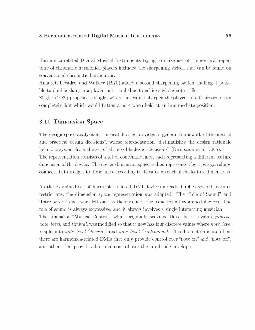
3 Harmonica-related Digital Musical Instruments 56
Harmonica-related Digital Musical Instruments trying to make use of the gestural reper-toire of chromatic harmonica players included the sharpening switch that can be found onconventional chromatic harmonicas.Hillairet, Lecadre, and Wallace (1970) added a second sharpening switch, making it possi-ble to double-sharpen a played note, and thus to achieve whole note trills.Ziegler (1989) proposed a single switch that would sharpen the played note if pressed downcompletely, but which would flatten a note when held at an intermediate position.
3.10 Dimension Space
The design space analysis for musical devices provides a “general framework of theoreticaland practical design decisions”, whose representation “distinguishes the design rationalebehind a system from the set of all possible design decisions” (Birnbaum et al. 2005).The representation consists of a set of concentric lines, each representing a different featuredimension of the device. The device dimension space is then represented by a polygon shapeconnected at its edges to these lines, according to its value on each of the feature dimensions.
As the examined set of harmonica-related DMI devices already implies several featuresrestrictions, the dimension space representation was adapted. The “Role of Sound” and“Inter-actors” axes were left out, as their value is the same for all examined devices. Therole of sound is always expressive, and it always involves a single interacting musician.The dimension “Musical Control”, which originally provided three discrete values process,note–level, and timbral, was modified so that it now has four discrete values where note–levelis split into note–level (discrete) and note–level (continuous). This distinction is useful, asthere are harmonica-related DMIs that only provide control over “note on” and “note off”,and others that provide additional control over the amplitude envelope.

3 Harmonica-related Digital Musical Instruments 57
distributed exte
nsive
none
few
low output
multim
odal
many
local
RequiredExpertise
MusicalControl
timbral
note-level
(continuous)
note-level
(discrete)
process
Distributionin Space
Degrees of Freedom[Inputs]
Feedback Modalities[Output]
Fig. 3.23 – Dimension Space representation based on a model adapted fromBirnbaum et al. (2005).
Dimension space representations were created for eleven devices and are shown inFig. 3.24. They should not be seen as absolute measures, but are meant to give a sense ofthe differences and similarities of the devices in relation to each other.
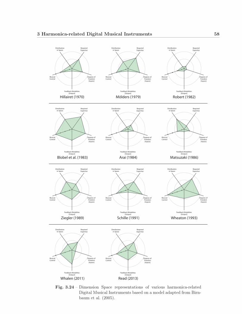
3 Harmonica-related Digital Musical Instruments 58
RequiredExpertise
MusicalControl
Distributionin Space
Degrees of Freedom[Inputs]
Feedback Modalities[Output]
Arai (1984)
RequiredExpertise
MusicalControl
Distributionin Space
Degrees of Freedom[Inputs]
Feedback Modalities[Output]
Blobel et al. (1983)
RequiredDistributionExpertise
MusicalControl
in Space
Degrees of Freedom[Inputs]
Feedback Modalities[Output]
Matsuzaki (1986)
RequiredExpertise
MusicalControl
Distributionin Space
Degrees of Freedom[Inputs]
Feedback Modalities[Output]
Read (2013)
RequiredExpertise
MusicalControl
Distributionin Space
Degrees of Freedom[Inputs]
Feedback Modalities[Output]
Whalen (2011)
RequiredExpertise
MusicalControl
Distributionin Space
Degrees of Freedom[Inputs]
Feedback Modalities[Output]
Schille (1991)
RequiredExpertise
MusicalControl
Distributionin Space
Degrees of Freedom[Inputs]
Feedback Modalities[Output]
Ziegler (1989)
RequiredExpertise
MusicalControl
Distributionin Space
Degrees of Freedom[Inputs]
Feedback Modalities[Output]
Wheaton (1993)
RequiredExpertise
MusicalControl
Distributionin Space
Degrees of Freedom[Inputs]
Feedback Modalities[Output]
Mölders (1979)
RequiredExpertise
MusicalControl
Distributionin Space
Degrees of Freedom[Inputs]
Feedback Modalities[Output]
Robert (1982)
RequiredExpertise
MusicalControl
Distributionin Space
Degrees of Freedom[Inputs]
Feedback Modalities[Output]
Hillairet (1970)
Fig. 3.24 – Dimension Space representations of various harmonica-relatedDigital Musical Instruments based on a model adapted from Birn-baum et al. (2005).

3 Harmonica-related Digital Musical Instruments 59
3.11 Geographical distribution
It is interesting to note where most of these inventions were claimed. The main countriesinclude Germany, the USA, Japan, and France.The harmonica was invented and marketed in the German-speaking countries, which couldexplain the interest of German-speaking inventors in the development of a harmonica-related DMI. The USA was always the main importing nation of harmonicas, and it isthere that important playing styles and techniques were developed. Harmonicas are verypopular in France as well, ever since the early importation of harmonicas from Germany(Berghoff 2001).Japanese inventors’ patents were usually associated with big electronic companies. Arai(1984) and Matsuzaki (1986) filed their patents in association with Casio Computer Ltd.,and Kondo (1997) with Sony Corp. One American inventor, Wheaton (1993) filed hispatent in association with Yamaha Corporation.There are a few Chinese patents as well (Li and Li 1990; Zhang and Zhang 1993). Theinterest of Asian inventors could be explained with the East Asian tradition of using reedinstruments such as the Chinese sheng, the Japanese sho, the Vietnamese Khene, and theThai Pi, as well as the large, well-organized harmonica scene in Asia (Eyers 2011).
3.12 Availability
Harmonica-related DMI design is an active field of product development. At the time ofthe publication of this work, at least three devices were currently under development or ina beta testing phase. The Jamboxx is sold commercially and the XHarp is in a pre-orderingstage of development.Web searches for all reviewed devices showed that most of them, including devices associ-ated with Yamaha, Casio, or Sony, are not currently produced for the mass market.One of the formerly most successful harmonica-related DMIs – the Millioniser 2000 – isdifficult to find today. Rock Erickson, the American spokesman and distributor of theMillioniser, stated in a phone call (personal communication, June 5, 2014) that only a totalof 100 instruments were produced.

3 Harmonica-related Digital Musical Instruments 60
3.13 Conclusion
In this chapter, a patent review of harmonica-related digital musical instruments was pre-sented. Different sensor system designs for the capture of musical excitation, selection, andmodification gestures were described.Devices were compared in terms of applicable harmonica playing techniques, tunings, andother categories. A focus was set on attempts to measure the note bending technique (orto translate this technique to another body part).Possible sound synthesis approaches were discussed and Dimension Space graphs were cre-ated for a selection of harmonica-related DMI in order to highlight their main features ina glance.
61
4 | Harmonica PerformanceGesture Study
In order to study the gestural interaction between performer and instrument, a study set-ting was created, involving the Qualisys1 motion capture system available at CIRMMT.Experienced harmonica players’ performances were recorded with synchronized motion cap-ture, audio, and video footage, as well as sensor data from a force-sensing resistor mountedon top of the device.
The acquired data allowed for a better visual examination of the musicians’ gestures, as wellas for numerical analyses. However, the limited data set of five participants does not allowfor quantitative approved statements that apply to the entirety of expert harmonica players.
Relationships between jaw opening and fundamental frequency, distance between harmon-ica body and cupping hand versus spectral centroid, maximum hand cupping frequency,and orientational pitch of the harmonica body were investigated.
The harmonica used in this study was a Hohner “Special 20 Marine Band”, which canbe considered a general standard, as indicated by Johnston (1987).
For a detailed description of the technical setup, please refer to Annex A (HarmonicaPerformance Gesture Study appendices).1 http://www.qualisys.com/
2014/11/29
4 Harmonica Performance Gesture Study 62
4.1 Participant recruiting and study organisation
Five participants were recruited from the Montréal community of harmonica performers, aswell as the Harp-L mailing list (with permission). All were males with more than 10 yearsof experience (17.6 years average). They all play the diatonic harmonica, but participantone performs predominantly on a chromatic harmonica.
The participants rated their level of experience with different playing techniques on a1 to 10 scale. The ratings were generally very high (Appendix A, sec. A.3 Question-naire responses).Participants were asked to rate their quality of performance during the study on a second1 to 10 scale. These ratings were also very high, with none of the ratings below 7, whichwe consider an acceptable quality for this study.
Upon showing interest for the study, the participants were provided with sample audiorecordings of two piece excerpts (described below), and were asked to practice the piece athome before the date of the experiment.The participants were compensated for their time and effort with 30$.
The study was approved by the McGill Research Ethics Board II (Appendix A, sec. ????).
4.1.1 Marker placement
In the conveyed user study, a total of 21 passive markers were attached to the right hand ofthe participants. Three markers were used for each finger, so that one marker was attachedto the top middle surface of each finger’s bone segment.Three markers were attached to the top of the left hand.
For one task of the study, only two markers were attached to the participants’ cheek andbottom of the chin (cf. sec. 4.2.1.1 Note bending).
The harmonica was modified with a wooden cross with markers attached, in order tobe able to calculate the position and inclination of the harmonica’s body at any time.
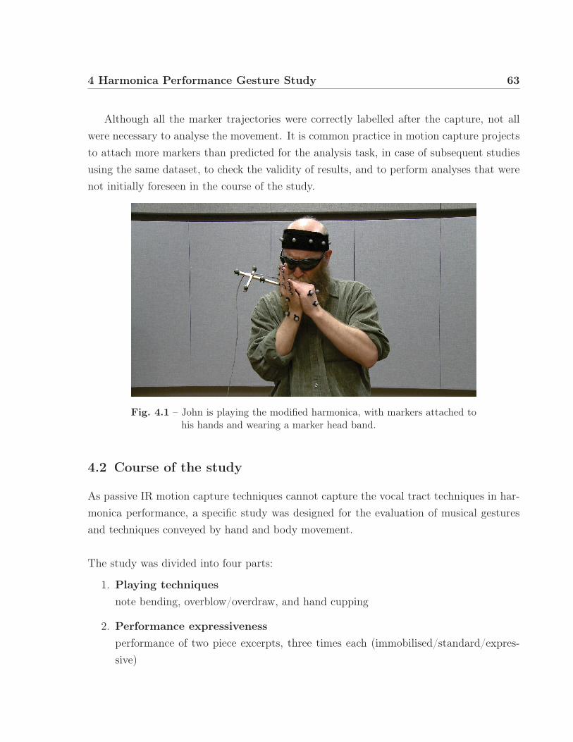
4 Harmonica Performance Gesture Study 63
Although all the marker trajectories were correctly labelled after the capture, not allwere necessary to analyse the movement. It is common practice in motion capture projectsto attach more markers than predicted for the analysis task, in case of subsequent studiesusing the same dataset, to check the validity of results, and to perform analyses that werenot initially foreseen in the course of the study.
Fig. 4.1 – John is playing the modified harmonica, with markers attached tohis hands and wearing a marker head band.
4.2 Course of the study
As passive IR motion capture techniques cannot capture the vocal tract techniques in har-monica performance, a specific study was designed for the evaluation of musical gesturesand techniques conveyed by hand and body movement.
The study was divided into four parts:
1. Playing techniquesnote bending, overblow/overdraw, and hand cupping
2. Performance expressivenessperformance of two piece excerpts, three times each (immobilised/standard/expres-sive)

4 Harmonica Performance Gesture Study 64
3. Free improvisationfree improvisation of two sequences, one slower and one faster
4. Evaluation of harmonica-related DMIs (presented in Chapter 5)participants were presented harmonica-related DMIs Jamboxx and Millioniser to test
4.2.1 Playing techniques
In the first part, participants were asked to perform basic playing techniques, such as notebending and hand cupping.Overblowing and overdrawing was performed as well, although the harmonica used wasnot “broken in” (the reeds were not embossed) to allow for easier overbending. All ofthe participants were uncomfortable with this condition, which is why the data was notanalysed.
4.2.1.1 Note bending
Referring to the problem of measuring or translating the note bending technique, as alreadymentioned in Chapter 3 sec. 3.4.1, the relationship between the note bending techniqueand jaw opening was investigated.
There is some evidence that jaw opening is correlated to the pitch of different vowelsin singing (Sundberg and Skoog 1997; Austin 2007). Given that note bending can be de-scribed in an analogy to unvocalised vowel sounds (Baker 1999) these findings might partlyapply to the note bending technique as well.The distance between a set of two markers attached to the cheek and chin of the partici-pant was calculated for each frame, and the fundamental frequency of the audio signal wasestimated using the YIN algorithm (De Cheveigné and Kawahara 2002). When plotted tothe same graph, a relationship becomes obvious (cf. Figs. 4.2 and 4.3). The fundamentalfrequency decreases along with the distance between cheek and chin, which suggests thatjaw opening is indeed connected to the note bending technique.The jaw can, of course, be opened independently, and not just while using the note bendingtechnique. Thus, jaw opening should only be used with caution as a direct input variableto any digital musical instrument.

4 Harmonica Performance Gesture Study 65
However, it might still prove to be useful to investigate, as an example, the employmentof a distance-measuring apparatus attached to the sliding mouthpiece of a slide-basedharmonica-related DMI. This could provide a more intuitive translation of the note bendingtechnique to another gesture – in this case, the displacement of the chin.
19.4 20.4 21.4
127
128
129
130
131
132
Time t in seconds
1.48
1.5
1.52
1.54
1.56
1.58
1.6
1.62
Est
imat
ed f
un
dam
enta
l fre
qu
ency
f0
(oct
ave
re:
440H
z)
Dis
tan
ce b
etw
een
mar
kers
CH
EE
K a
nd
CH
IN (
mm
)
Fig. 4.2 – A graph displaying the cheek–chin distance and the estimate offundamental frequency during a hole 8 blow bend to E� and back.
4.7 5.7 6.7
130
131
Time t in seconds
0.9
0.95
1
1.05
Est
imat
ed f
un
dam
enta
l fre
qu
ency
f0
(oct
ave
re:
440H
z)
Dis
tan
ce b
etw
een
mar
kers
CH
EE
K a
nd
CH
IN (
mm
)
Fig. 4.3 – A graph displaying the cheek–chin distance and the estimate offundamental frequency during a hole 3 draw bend to B� – A – A�.

4 Harmonica Performance Gesture Study 66
Hand Cupping
The hand cupping gesture can be seen as a filter to the output sound of the harmonica,affecting the sound’s brightness. This effect is used extensively in harmonica performance.Thus, it is interesting to investigate how the hand cupping technique can modify the bright-ness in particular.The spectral centroid is a good predictor of a sound’s brightness (Grey and Gordon 1978).In figs. 4.4 and 4.5, spectral centroid is plotted against the distance of the harmonica’scenter point to one marker placed on the back of the hand. This, of course, is a rudimen-tarily simplified representation of the hand cupping gesture, but it still shows interestingresults.The participants were asked to perform a slow hand cupping gesture and were providedwith a click track prior to the capture, so that they could internalize the tempo of 30 BPM.Represented by the blue line plot, the over time increasing and decreasing distance of thehand to the harmonica’s body can be seen.The red line plot, representing the spectral centroid and thus indicating higher brightnesswith higher values, mostly follows the tendency of the blue line. This suggests that withincreasing distance (and less cupping), the brightness of the sound intensifies.
1 2 3 4 5 660
70
80
90
100
Time t in seconds
Dis
tan
ce b
etw
een
har
mo
nic
a b
od
y ce
ntr
ean
d b
ack
sid
e o
f th
e cu
pp
ing
han
d (
mm
)
4000
5000
Est
imat
ed s
pec
tral
cen
tro
id (
Hz)
Fig. 4.4 – A graph displaying the distance between the harmonica body centreversus the spectral centroid during a performance of slow handcupping (participant 1).
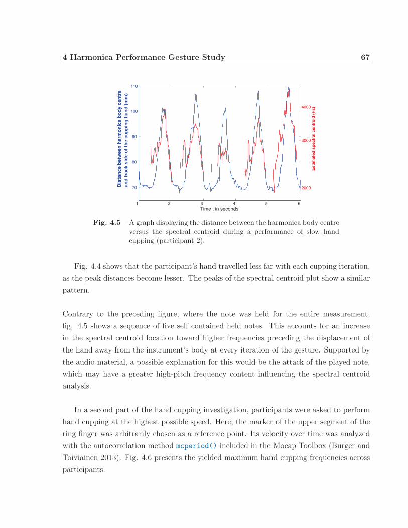
4 Harmonica Performance Gesture Study 67
1 2 3 4 5 6
70
80
90
100
110
Time t in seconds
Dis
tan
ce b
etw
een
har
mo
nic
a b
od
y ce
ntr
ean
d b
ack
sid
e o
f th
e cu
pp
ing
han
d (
mm
)
2000
3000
4000
Est
imat
ed s
pec
tral
cen
tro
id (
Hz)
Fig. 4.5 – A graph displaying the distance between the harmonica body centreversus the spectral centroid during a performance of slow handcupping (participant 2).
Fig. 4.4 shows that the participant’s hand travelled less far with each cupping iteration,as the peak distances become lesser. The peaks of the spectral centroid plot show a similarpattern.
Contrary to the preceding figure, where the note was held for the entire measurement,fig. 4.5 shows a sequence of five self contained held notes. This accounts for an increasein the spectral centroid location toward higher frequencies preceding the displacement ofthe hand away from the instrument’s body at every iteration of the gesture. Supported bythe audio material, a possible explanation for this would be the attack of the played note,which may have a greater high-pitch frequency content influencing the spectral centroidanalysis.
In a second part of the hand cupping investigation, participants were asked to performhand cupping at the highest possible speed. Here, the marker of the upper segment of thering finger was arbitrarily chosen as a reference point. Its velocity over time was analyzedwith the autocorrelation method mcperiod() included in the Mocap Toolbox (Burger andToiviainen 2013). Fig. 4.6 presents the yielded maximum hand cupping frequencies acrossparticipants.

4 Harmonica Performance Gesture Study 68
Participants 1, 2, and 5 exhibited higher maximum frequencies than participants 3 and4, but the frequencies are quite close together. Participant 5 showed a considerable maxi-mum hand cupping frequency of 8.1 Hz.The differences can not be explained with the participants’ years of practice, as participant3 and 4 showed an inferior maximum hand cupping frequency while having most years ofpractice. However, the participant’s age could play a role: Participant 1, 2, and 5 weresignificantly younger in age than participant 3 and 42.
1 2 3 4 5 Average6.5
7
7.5
8
8.5
Fre
qu
ency
of
han
d c
up
pin
g g
estu
re
Participant
Frequency of fastest possible hand cuppingtremolo measured at position RH4U
Fig. 4.6 – A plot showing the hand cupping freqency of the participants whenasked to perform as fast as possible.
4.2.2 Performance expressiveness and orientational pitch
Participants were asked to perform two piece excerpts three times each. For the threeiterations of the piece performance, participants were asked to perform immobilised (“moveas little as possible”), naturally (standard) and exaggeratedly expressive. The terminologywas adapted from Wanderley (2002) and describes the amount of movement.
2 Age differences are estimates, as information on the age was not requested in the questionnaire.
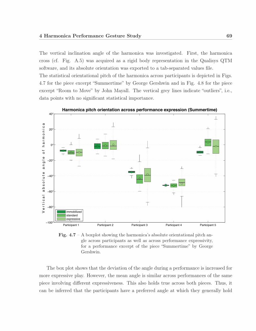
4 Harmonica Performance Gesture Study 69
The vertical inclination angle of the harmonica was investigated. First, the harmonicacross (cf. Fig. A.5) was acquired as a rigid body representation in the Qualisys QTMsoftware, and its absolute orientation was exported to a tab-separated values file.The statistical orientational pitch of the harmonica across participants is depicted in Figs.4.7 for the piece excerpt “Summertime” by George Gershwin and in Fig. 4.8 for the pieceexcerpt “Room to Move” by John Mayall. The vertical grey lines indicate “outliers”, i.e.,data points with no significant statistical importance.
Participant 1 Participant 2 Participant 3 Participant 4 Participant 5
V e
r t
i c a
l a
b s
o l
u t e
a
n g
l e
o f
h a
r m
o n
i c
a
Harmonica pitch orientation across performance expression (Summertime)
immobilizedstandardexpressive
Fig. 4.7 – A boxplot showing the harmonica’s absolute orientational pitch an-gle across participants as well as across performance expressivity,for a performance excerpt of the piece “Summertime” by GeorgeGershwin.
The box plot shows that the deviation of the angle during a performance is increased formore expressive play. However, the mean angle is similar across performances of the samepiece involving different expressiveness. This also holds true across both pieces. Thus, itcan be inferred that the participants have a preferred angle at which they generally hold
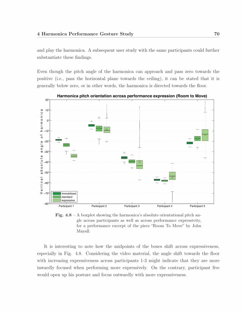
4 Harmonica Performance Gesture Study 70
and play the harmonica. A subsequent user study with the same participants could furthersubstantiate these findings.
Even though the pitch angle of the harmonica can approach and pass zero towards thepositive (i.e., pass the horizontal plane towards the ceiling), it can be stated that it isgenerally below zero, or in other words, the harmonica is directed towards the floor.
Participant 1 Participant 2 Participant 3 Participant 4 Participant 5°
°
°
°
°
°
°
°
°
°
°
V e
r t
i c a
l a
b s
o l
u t e
a
n g
l e
o f
h a
r m
o n
i c
a
Harmonica pitch orientation across performance expression (Room to Move)
immobilizedstandardexpressive
Fig. 4.8 – A boxplot showing the harmonica’s absolute orientational pitch an-gle across participants as well as across performance expressivity,for a performance excerpt of the piece “Room To Move” by JohnMayall.
It is interesting to note how the midpoints of the boxes shift across expressiveness,especially in Fig. 4.8. Considering the video material, the angle shift towards the floorwith increasing expressiveness across participants 1-3 might indicate that they are moreinwardly focused when performing more expressively. On the contrary, participant fivewould open up his posture and focus outwardly with more expressiveness.

4 Harmonica Performance Gesture Study 71
4.2.3 Free improvisation
The participants were asked to perform one slow and one fast improvisation, without anyfurther instructions given. The first 60 seconds of each improvisation were captured.The material was then analysed using Matlab. Both finger pressure and harmonicainclination plots were created and exported as scroll plots to video files. The harmonicainclination plot also included the relative angle of the harmonica’s inclination to that of thehead (seen as green lines in Fig. 4.9), which is found by calculating the difference betweenhead band inclination data and harmonica cross inclination data.The difference data can only be used to visually indicate relative changes, as the head bandangle (as worn on the head) was not normalized to absolute angle values. However, whencompared to the harmonica cross inclination and omitting an angle offset, it correspondsto the angle of the harmonica relative to the player’s mouth.
Fig. 4.9 – An example frame of a video scrollplot used in the annotation ofthe improvisation performance footage.
The video scroll plots were imported into the video annotation software ELAN (Sloetjesand Wittenburg 2008) in order to find visual indicators of the relationships present within

4 Harmonica Performance Gesture Study 72
the data. ELAN was originally developed by the Max Planck Institute for Psycholinguisticsand supports multi-layered annotation of up to four synced video files and audio.While having an excellent feature set, unfortunately ELAN has no way to import andvisualise data (other than annotations) directly as TSV or CSV files, which is why the datahad to be imported as video footage. It was still found to be better suited for the task thanother annotation software such as VCode & VData3 or ANVIL4.
31 2
5
4
Fig. 4.10 – A screenshot of the ELAN software used for the visualisation andpartial annotation of the video files, displaying video footage 1,acquired Qualisys markers and harmonica rigid body definition 2,finger pressure data 3, harmonica inclination 4, and the annota-tion area 5.
3 http://social.cs.uiuc.edu/projects/vcode.html4 http://anvil-software.de/

4 Harmonica Performance Gesture Study 73
Observing finger pressure data
The visual examination of the improvisation sequences yielded no obvious relationship ofthe finger pressure data with the instrument’s inclination data, nor with recurrent gestures.Finger pressure didn’t alter specifically with any single playing technique, nor was it aconsistent indicator for phrasing and rhythmic sequences.
Observing the hand cupping gesture
The video footage was visually analysed to draw conclusions about the hand cupping tech-nique. Generally, participants opened the cupped hand more often on the bottom, keepingthe top hand placed on the harmonica. Other times, the hand’s posture was preserved whileit was moved to and from the instrument’s body. The vertical position of the right cuppinghand when touching the instrument remained relatively constant for all participants. Whenmoved away from the instrument’s body, the direction of movement was always towardsthe bottom. This might be related to the way the diatonic harmonica is usually held (cf.sec. 2.2.1), where the thumb supports the instrument from the bottom.
4.3 Conclusion
In this chapter, a motion capture study of harmonica performance gestures was presented.The participant selection process was described, and the course of the study outlined.Qualitative findings related to common playing techniques such as note bending and handcupping were shown. The relationship between instrument orientational pitch and ex-pressiveness was investigated, and footage of free harmonica improvisation was used toinvestigate relationships within the captured data.

74
5 | DMI Evaluationand Jamboxx Augmentation
5.1 Evaluation of harmonica-related DMIs
As a second part of the conducted study, four of the five participants were presented withtwo harmonica-related DMIs: A Jamboxx 1 prototype and the Millioniser 2000 2. Bothdevices are slide-based harmonica-related DMIs, where the notes are selected by sliding amouth piece in the associated horizontal position. The devices were discussed informallywhile examining them together with the performer. The video footage of the discussionwas later reviewed and comments were annotated.
When discussing the devices with the participant, a number of research questions werekept in mind.
1. Is the proprioception trained using an acoustic harmonica easily transferred to aslide-based sensing system?
2. Does the slide’s movement resistance interfere in the note selection process?
3. Is the up/down tilt movement a good substitute gesture for the note bending tech-nique?
4. Is the visual feedback important?
The comments made by the participants indicate design flaws that are only discernible byexpert harmonica players, and thus very interesting to note. The following summary is1 http://www.jamboxx.com2 http://www.millioniser.com
2014/11/29
5 DMI Evaluation and Jamboxx Augmentation 75
a particular case study and not intended to patronize the developments, but to provideconstructive criticism applicable to the entire field of harmonica-like DMI design.
5.1.1 Jamboxx
The Jamboxx prototype provided by My Music Machines, Inc. was presented first. It wasmounted on a microphone stand with the original mounting equipment and connected toa PC with an installed version of the Jamboxx Pro Suite software (cf. Fig. 3.21).
5.1.1.1 Bypass air
The provided mouthpiece of the device did not include a bypass channel for the blown/-drawn air. Three out of four participants reported that they were uncomfortable with thefact that the air does not flow through the mouthpiece. One stated that it felt as if hewas not breathing. The fourth participant mentioned that it does not pose a problem, anddepends on experience. He also pointed out that this feature enables holding a note whilebreathing simultaneously.
5.1.1.2 Air pressure controlled intensity
The air pressure controlled intensity of the sound output was criticised by two participants:the resolution would be too small and the note-triggering threshold too high. One partic-ipant stated that the quietest note he was able to play on the Jamboxx was already asloud as a mezzo-forte. Half of the participants did not recognize the device as being grad-ually pressure-sensitive at all, and thought it was only processing discrete on and off values.
One participant pointed out that he was unable to use the tongue articulation technique.This might also be due to the use of a pressure threshold that needs to be attained in or-der to trigger a tone. The tongue articulation technique, however, involves fast successivezero-crossings between positive and negative breath pressure, so that a direct translationof breath pressure to amplitude envelope would be more purposeful in this context.

5 DMI Evaluation and Jamboxx Augmentation 76
5.1.1.3 Ergonomics
Two participants stated that the mouth piece does not respond to their ergonomic needs.The embouchure around the small mouthpiece nipple would require constant effort, whichleads to earlier fatigue during performance.
5.1.1.4 Mouth piece slide friction
None of the participants had problems with the mouth piece slide friction, and two reportedthat it was very fluid and easy to slide. One reported that he was able to quickly jumpfrom one note position to another just like on a standard Richter-tuned harmonica. Whenasked to perform the diatonic scale on the second octave, all participants showed that itwas possible and highly probable that they could adapt quickly. The difficulty of noteselection with the slide was rated as being medium-difficult.
5.1.1.5 Note spacing
Two participants mentioned that the spacing between selectable note positions on the slideis too big, so that the way to travel from one note to another is long. This leads to fatigueand slows down the performance speed. Again, two participants reported difficulties in thenote selection process due to a difference in spacing between the leftmost and second-to-leftnote, as well as the second and third note, and suggested that all note positions should beequidistant.
5.1.1.6 Pitch bend
The Jamboxx has a pitch bend functionality related to up/down movement of the devicewhen mounted on a stand, or the turning of a knob on the left side when unmounted.The rotary encoder (cf. Fig. 3.10) is used in both settings as the input sensor. Theprototype mapping was such that upward tilting bent the pitch downwards, and downwardtilting bent the pitch upwards. All of the participants reported this behaviour as beingcounter-intuitive, and rated the feature as being very unnatural. The Jamboxx Pro Suitesoftware includes a calibration wizard that allows the user to choose whether to use thedevice mounted or free-hand, but this does not reverse the sensor data.When playing in free-hand mode, one participant stated that he would prefer the knob to
5 DMI Evaluation and Jamboxx Augmentation 77
be on the right side of the device. Another participant stated that he would generally prefera lever on the back side of the device for pitch bend gestures, whereas a second participantsuggested a pitch bend wheel like those widely used on keyboard synthesisers, as well asthe use of a lip pressure or bite pressure sensor.When asked about the use of a self-centering spring-mounted knob that would enable theinstrument to move back to the neutral note bend position, the participants approved.
5.1.1.7 Distribution in Space
Combined up/down tilt movement (when mounted) and mouth piece slide movement wasexperienced by two participants as resulting in a too-large movement space, whereas oneparticipant found it to be acceptable. Furthermore, one participant mentioned that thehands-free use of the controller significantly facilitates the movement. Not only could ahead displacement gesture be used to select a note or pitch bend, but hand movementcould also be used to displace and tilt the device. The use of the head and hands toaccomplish a task together may improve the speed and accuracy of the gesture, and thusthe accuracy of note selection or pitch bend.Another interesting suggestion was to modify the sliding mechanism from being linearto being somewhat circular. This would therefore better correspond to the angular yawmovement of the head.
5.1.1.8 Feature limitation
One participant spoke out in favour of limiting the pitch bend functionality so that only thenotes that are bendable on a Richter-tuned harmonica could be bent using the Jamboxx.This demonstrates a point of view that is also discussed in the theory of product design.The first design law of John Maeda’s book “The Laws of Simplicity” is that of (methodical)reduction (Maeda 2006). In development, input devices can easily become overcomplicated.Simple removal or masking of features can add to the intuitiveness of the device, which isalso improved by enabling the use of a known gestural repertoire.Another participant argued against this notion and stated that this feature extrapolationis a big plus.
5 DMI Evaluation and Jamboxx Augmentation 78
The fact that the pitch bend functionality only bends one semitone up or down, whereasa Richter-tuned harmonica can be bent down up to three semitones depending on the airchannel was criticized by two participants.Furthermore, two other participants remarked that the visual feedback indeed indicates thepitch bend on a virtual pitch wheel, but not on the virtual keyboard displayed as part ofthe software’s graphical user interface. This caused confusion among the participants.
5.1.1.9 Tactile feedback
When asked about the use of a tactile bump strip (which was not available at the time ofthe study), three participants answered in the affirmative. One of them, however, thoughtof it as being only useful for the learning stage and pointed out that expert harmonicaplayers are used to playing their instrument “blindly” without tactile cues.
5.1.1.10 Chord functionality
The Jamboxx Pro Suite includes a functionality that can add chords to the played note.Participants criticized this as not being useful, as the chords are always in the same modefor all notes. On an acoustic diatonic harmonica, it is possible to play major chords, majorseventh chords and single notes interchangeably by letting air flow through one or multipleholes.In the same way, octave playing and split intervals (cf. sec. 2.2.2) is made impossible onthe Jamboxx.
5.1.1.11 General interest
While all participants showed great interest in the device, they were all skeptical aboutwhether they would use it personally. One participant stated that even if he can applyhis own musical skills, it still feels like learning a completely new instrument. Anotherparticipant was skeptical about whether he would be ever able to master the instrument.
5.1.2 Millioniser 2000
The Millioniser 2000 is not manufactured anymore, and there are only a few used ex-emplars selling. This is why only the controller, but not the synthesiser unit, could be
5 DMI Evaluation and Jamboxx Augmentation 79
procured. Thus, the participants could only evaluate the interaction with the controllerwithout any audible feedback.
In order to give an impression of how the Millioniser is played and how it sounds, theoriginal 1983 advertisement video of the Millioniser 2000 was shown to the participants(millioniser2000 2009). An interesting off-topic comment on the video mentioned that eventhough it shows someone playing the Millioniser 2000, the participants did not perceivehim as being a master of the instrument, which inspired skepticism among all the partici-pants about the quality of the device.
As the device was presented second and the study duration was limited to three hours,the device was not examined to the same extent as the Jamboxx.
5.1.2.1 Half tone lever
The device’s half-tone lever was instantly recognized by all participants as having a similarfunction to a switch button on a chromatic harmonica. This suggests that if any button orlever is placed on the frontal left side of a harmonica-related DMI, its function is anticipated.This user expectation can be used for an intuitive design.
5.1.2.2 Slide steps
The mouthpiece slider of the Millioniser 2000 does not slide smoothly, but in incrementsthat stop at small notches for every selectable note position. This can be seen as an ame-lioration to the note selection task. However, one participant reported that the perceptiblebumps would cause discomfort when switching rapidly between two adjacent notes.
5.1.2.3 Size of the instrument
When compared to the small and lightweight diatonic harmonica that becomes an integralpart of the performer’s hand, one participant said that the sheer size of the Millioniser2000 prevents it from becoming easily adapted for proprioception. Of course, engineerstoday would be able to develop a smaller and lighter device with the same capabilities, butit is interesting to note that small size, weight, and portability are features important toexpert harmonica players.

5 DMI Evaluation and Jamboxx Augmentation 80
5.2 Instrument Augmentation
The aforementioned Jamboxx was chosen as a base model for the creation of a novel digitalmusical instrument via instrument augmentation.Building upon an existing DMI offered the possibility to focus on the application and eval-uation of the findings from the motion capture study, as well as DMI evaluation instead ofreinventing the note selection and excitation gesture sensor systems.
The DMI developers at My Music Machines, Inc., provided a Jamboxx gestural controllerused as a base model. The electronics inside the Jamboxx were left untouched. Instead,a separate sensor acquisition system was added to the device. The input from Jamboxxwas combined with that from the sensor system in the Jamboxx Augmentation software,written in Max.
The Jamboxx-based augmented prototype is designed to incorporate additional sensorscapable of capturing musical gestures that were not considered in the original design, suchas hand cupping, finger pressure, and tilting the instrument.
Base model
The features of the base model are described in Chapter 3, and also presented in Whalen,Luther, and DiCesare (2011). They involve a slide-mounted mouth piece that includes adifferential pressure sensor, and an infinite turn rotary potentiometer.No attempt was made to transmit the sensor data wirelessly. As the development wasbased on the cabled Jamboxx, the increased complexity of a wireless transmission was notjustified. Furthermore, many harmonica players are used to playing the harmonica whileeven holding a microphone at the same time, so the cables seemed to be an acceptableobtrusiveness to performance. Perry Cook shares the opinion that “Wires are not thatbad (compared to wireless)”. In his 2001 paper Principles for Designing Computer MusicControllers (Cook 2001), he also states that “Programmability is a curse”, advocating formore fixed and simple designs over the continuous addition of new features. This advicewas implemented by the use of a fixed mapping, as described in the Mapping layer section(5.2.2.3).

5 DMI Evaluation and Jamboxx Augmentation 81
Fig. 5.1 – An overview of the prototype with annotated sensor system features.
5.2.1 Sensor system design
An Arduino Micro single-board microcontroller was used to sample and transmit sensordata to the computer. The Arduino IDE prototyping platform allows the writing of afirmware script that can be loaded into the EEPROM storage of the microcontroller, sothat it can perform various tasks independently from the sound synthesis computer.
An emulated serial connection through USB was created, which operates with call andresponse communication and sends a packet of sensor readings only when the computerrequests it (see appendix B). This way, sensor readings do not pile up in the serial bufferand cause a lag in response time if the computer reads the packets slower than the Arduinosends them.
5.2.1.1 Finger Pressure
The goal of integrating a finger pressure sensor to the Jamboxx design is to provide analternative to the pitch bend wheel currently used to translate the note bending gesture onthe Jamboxx.While the wheel provides pitch bend functionality in both up and down directions, thenote bending technique on an acoustic harmonica only provides a means of lowering the

5 DMI Evaluation and Jamboxx Augmentation 82
4
32
1
(a) Top view of the electronics unit,showing the current-switching tran-sistor 1, the analogue-to-digital con-verter 2, the cabelling to the Ar-duino 3, and the power supplysocket 4.
1
2
(b) Bottom view of the electronics unit, depict-ing the Arduino 1 and showing the locationof the Plolu MinIMU 9 v2 2.
Fig. 5.2 – Additional external electronics unit.
pitch (cf. sec. 2.2.3). Some participants of the user study described in section 5.1.1.6mentioned their preference for this apparent feature limitation over feature extrapolation.They argued that the note bending functionality should resemble that of the acoustic har-monica.
Finger pressure through isometric force is measured in a single direction and might bemore suitable as a translation for the note-bending gesture. It has already been proposedfor pitch control by Wheaton (1993).The fingers of the left hand naturally rest on the top of the acoustic harmonica duringperformance without having any function in the modification of the sound. We could takeadvantage of this spare bandwidth by placing the gesture acquisition in the same physicalspace. A finger pressure sensor can be actuated instantly from the natural rest position,which might increase the intuitiveness of the device.
An Interlink Long Force Sensing Resistor (FSR) 4083 was used in the current design. TheFSR is a sensor containing a conductive polymer which changes its electrical resistanceproportional to the applied force. The sensor is low-cost and very thin, but only offers lim-3 http://www.interlinkelectronics.com/FSR408.php

5 DMI Evaluation and Jamboxx Augmentation 83
ited precision. It may be useful to investigate to which degree the low repeatability impairsthe learnability of the pitch bend technique on the device, given the high sensitivity of thehuman ear to pitch fluctuations.
The FSR was firmly attached to the top left surface of the Jamboxx. Synthetic elasticfoam was cut into a semi-cylindrical shape and attached on the top of the FSR by means ofelectrical tape. This way, a bigger surface area could be used to actuate the sensor. Also,due to its expansion property, the foam contributes proprioceptive feedback, which mightfacilitate the control of finger pressure by taking away its purely isometric aspect. Theaddition of foam was inspired by the T-Stick (Malloch and Wanderley 2007) and the MetaInstrument (Laubier 1998).
5.2.1.2 Hand Cupping
The hand cupping gesture (as described in sec. 2.2.7) is fairly complex. The hand acts asa deflector and floodgate for the air stream. Thus, it is very dynamic in terms of occupiedphysical space, position in space, distance to the instrument, and solidity, providing differ-ent levels of airtightness and deflection.
In order to represent the gesture appropriately, we need to know the approximate an-gle of the covering hand, as well as the amount of “airtightness” when cupping the handaround the device (which is, of course, not to be taken literally as there is no actual airflow coming out of the back of the Jamboxx ).Thus, the most straightforward approach is an array of distance sensors. With a minimumof four distance sensors, the approximate angle of the hand can already be determined byapplying trigonometry. The smaller the distance across the array sensors, the higher theassumed “airtightness”.
Obvious candidates for sensing distance are capacitance sensors, ultrasonic distance sensorsand optical proximity sensors.However, ultrasonic distance sensors have a narrow beam width, limited resolution, andexperience drift and interference from changes in the environment (Paradiso and Gershen-feld 1997). More importantly, the sensor output is saturated if a minimum distance of the

5 DMI Evaluation and Jamboxx Augmentation 84
object to the sensor is not kept4. This renders the ultrasonic distance sensor unsuitable forthe hand cupping application, as the gesture involves movement very close to the instru-ment’s body.
Capacitive sensors are mostly used for touch sensing (for example, in touch screens), butthe same principle may be used to measure distance. This technique is then called elec-tric field proximity sensing, based on the principle that the recharge time of a capacitiveantenna is proportional to its distance from an object such as the performer’s hand. Thisprinciple is used by the Theremin to control amplitude and frequency of the output soundwith hand (and body) proximity to each antenna. A minimum of three electrode antennasare needed to determine the 3D position of a fixed-size mass such as the hand (Paradisoand Gershenfeld 1997).
Optical proximity sensors are usually pairs of light emitters and receivers, which mea-sure the amount of light reflected by an object. In order to minimize interference of visibleambient light, they usually operate in the infrared light range. As lamps (and especiallystage lights) emit infrared light as well, some interference can still occur to the sensor sig-nal.Due to these interferences, the sensor readings are non-monotonic. A sensor response iscalled non-monotonic when “[...] a sensor presents the same output in response to multipledifferent inputs” (Brum Medeiros and Wanderley 2014). In our application, the sensoryields low values if the hand is very close to the photo transistor (lack of reflected light),high values for medium distance, and low values for higher distances. This renders theunfiltered sensor input unusable for the use of a DMI, as the computer cannot determineif the hand is very near or very far away.
However, as the interference can be filtered fairly easily, and the infrared emitters andphoto transistors are low-cost and do not require a complex measurement circuit, the opti-cal sensing approach was chosen for the augmented Jamboxx design. In addition, previouswork by Tarabella (2000) – the Twin Towers DMI – had already proven that an infraredsensor system is suitable for the recognition of certain hand gestures. Here, an array of4 The minimum distance is usually bigger than several inches
(cf. e.g., http://www.maxbotics.com/Ultrasonic_Sensors.htm)

5 DMI Evaluation and Jamboxx Augmentation 85
four infrared distance sensors was used to determine the distance and rotation of the handwith respect to a reference frame.A variety of commercially available IR proximity sensors with on-board signal conditioningexist, some of which were considered in this design. However, the very common Sharp Dis-tance Measuring Sensors either exhibit a too-short or too-high sensor range5, as do manyother reflectance sensors originally designed for line-finding robots (such as the Pololu QTR-1A6). Instead, it was found to be more useful to work with more basic electric components,such as IR LEDs and IR photo transistors, and to condition the sensor signal inside theArduino’s ATmega32u4 microcontroller chip.
There are at least two conditioning approaches to minimizing the interference of ambi-ent infrared light to the sensor signal. First, the emitter signal can be modulated at ahigh frequency (kHz range) and demodulated at the receiver. As the ambient light onlyfluctuates at a low frequency, it is disregarded by the demodulation process. This filteringapproach is used, for example, in infrared remote controls for televisions. However, mod-ulation and demodulation require a higher number of components, including some whichare more expensive.
The second filtering approach is the use of difference sensor readings. The emitter isturned on and off in rapid succession, while the photo transistor voltage is read for bothstages. At the end of such a cycle, the voltage difference for ambient light only (emitterturned off), and both ambient light and reflection from the object (emitter turned on), iscalculated, yielding a one-dimensional set of values. The downside of this filtering methodis the resulting loss of sensor resolution.
The only reviewed device showing a means of measuring the hand cupping gesture (asdescribed in sec. 3.4 and Schille (1991)) employed only one single infrared light emitterand receiver pair. Thus, the sensing of a hand cupping gesture was reduced to a simpledistance measurement. The hand cupping sensor interface described in this work is capableof representing the gesture more accurately.5 http://www.sharpsme.com/optoelectronics/sensors/distance-measuring-sensors6 http://www.pololu.com/product/958

5 DMI Evaluation and Jamboxx Augmentation 86
Construction of the sensor interface
A quarter of a transparent PVC tube was cut off lengthwise so that it could be attached tothe edge of the Jamboxx. A total of 39 holes were drilled into the surface of the tube, in apattern shown on Fig. 5.3. The pattern allows for every photo transistor to be surroundedby six to eight emitters. The structure of the pattern and the high number of infrared lightemitters are needed to provide a more homogeneous and brighter illumination of the hand,which in turn ameliorates the sensor resolution and facilitates the processing of the handposition over the sensor. For this same reason, emitters with a radiation angle of 30° wereused.The holes fit the diameter of both the infrared emitter diodes and photo transistors exactly,so that the friction is sufficient to hold them in place.
1 2 3
6 7
4 5
8
Fig. 5.3 – Pattern layout of the infrared emitter (white) and photo transistor(grey) array.
Circuit design
As the infrared light emitters are only required to be turned on or off all at once, they canbe controlled by one single digital out pin on the Arduino. However, the Arduino is onlycapable of supplying a current of 40 mA7, which is not enough to power 31 infrared lightemitters.
7 http://arduino.cc/en/Main/arduinoBoardMicro

5 DMI Evaluation and Jamboxx Augmentation 87
A TIP 120 Darlington transistor was used to create a working circuit controlled by aseparate control circuit via the Arduino’s aforementioned digital out pin. The workingcircuit is connected to an external power supply providing a sufficient maximum current.The Arduino then merely switches the transistor, effectively opening or closing the workingcircuit, turning the infrared LEDs on or off.
Fig. 5.4 – A close-up view of the infrared emitter and photo transistor sensorarray.
In order to reduce the amount of wires going into the PVC tube, the infrared LEDswere connected in series of two or three units, yielding eleven instead of 31 wires. It wasnot possible to connect more then three (or maximum four) LEDs in series, as they show avoltage drop after every unit, limiting the number of units to 5V − (x · ∼ 1.2V )⇔ x ≈ 4.The current limiting resistors connected in series with each group of LEDs were calculatedas follows:
VR = VS − x ·VD,whereVR = series voltage, VS = supply voltage, x = number of LEDs, VD = voltage drop
R = VR
IR, where
R = current limiting resistance, IR = desired supply current

5 DMI Evaluation and Jamboxx Augmentation 88
The photo resistors are connected through a voltage divider with the eight input pins ofan MCP3008 analogue-to-digital converter, which is capable of reading the sensor voltagewith a 10 bit resolution.The Arduino communicates with the MCP3008 ADC over a Serial Peripheral Interface(SPI) connection by the means of a freely available Arduino library8.
5.2.1.3 Inclination
A Pololu MinIMU 9 v2 inertial measurement unit (IMU) was mounted onto the device, andconnected to the Arduino over a SPI connection, which is established using freely availableArduino libraries9.
This IMU uses a combination of accelerometers, gyroscopes, and magnetometers to deter-mine the velocity, orientation, and gravitational forces of the device in all three dimensions.
The current implementation only put the gyroscope raw data in effective use, so that asingle 3-axis gyroscope would suit the application as well. However, the IMU was available,and can be used for future work in exploring mappings of accelerometer data.
5.2.2 Software design
The visual programming language and IDE Max 6 – a common choice for prototypingDMIs, as well as lingua franca for computer-based live performance (Place and Lossius2006) – was chosen for the development of the Jamboxx Augmentation software. Thesoftware is comprised of three layers: the input signal processing and visualisation layer,the mapping layer, and the sound synthesis layer, which are described as follows.8 https://github.com/nodesign/MCP30089 https://github.com/pololu/, repositories l3g-arduino and lsm303-arduino
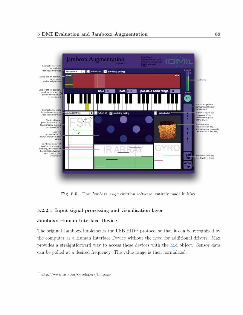
5 DMI Evaluation and Jamboxx Augmentation 89
Display of slide position,air pressure,
and wheel position
Display of hole position,resulting note and itspossible bend range
(in semitones)
Connection controlsfor additional sensors
(connected via USB)
Display of fingerpressure values (FSR),
its exponential movingdeviation (EMD)
Circle setrepresentation of
filtered phototransistorvalues
Combined display ofoverall phototransistor
intensity, and weightedhorizontal and vertical
hand position oversensor array
Connection controlsfor Jamboxx
(connected via USB)
Level meter
Buttons to store and recall synth settings
Button to re-set thezero point of the orientational pitchof the device
Rotating cuberepresentation (top)and gyroscope orientationrepresentation (bottom)
Button to open thesoftware synthesiser(NI Massive)
positttiiooonnnn,presssuuurreeeee,l posiitttiooonnn
positttiiooonnnn,ote anddd itttssend raannngggeeeemitoonnneesss))
n contttrroollssal sennsssooorrrssd via UUUUSSSBBBB))
y of finnngggeeeerrrues (FFFSSSRRRR)),al movvvvinnngggon (EMMMMDDDD))
Circleee ssseeeettntatioonnn oooofffftransisstttoooorrr
vaalluueeess
displaaayyy oooofffftransisstttoooorrrweighhhtteeedddd verrtticcaaaalition oooovvveeeerrrnsor aarrrraaayyyy
n contttrroollssJambbboooxxxxxxx
d via UUUUSSSBBBB))
LLLLeeeevvveeell met
BBBuuuutttttooons torrreeeccaaalll synt
BBBuuuutttttooon to zzzeeeerrooo pointoooorrrrieennntatiooooofff f ttthhhee dev
RRRooootttaaatting crrreeeppprreeesentaaaannnnddd ggyrosrrreeeppprreeesenta
BBBuuuutttttooon to sssoooooffttwwwware s(((NNNNNI MMMMassiv
Fig. 5.5 – The Jamboxx Augmentation software, entirely made in Max.
5.2.2.1 Input signal processing and visualisation layer
Jamboxx Human Interface Device
The original Jamboxx implements the USB HID10 protocol so that it can be recognized bythe computer as a Human Interface Device without the need for additional drivers. Maxprovides a straightforward way to access these devices with the hid object. Sensor datacan be polled at a desired frequency. The value range is then normalized.
10http://www.usb.org/developers/hidpage

5 DMI Evaluation and Jamboxx Augmentation 90
The slide position is visualized with a vertical bar sliding horizontally across a box, asseen in Fig. 5.5. The normalized floating-point slide position value is scaled to a range of1 to 10 and ceilinged to the nearest integer, according to the number of holes on a Richter-tuned harmonica. The range of the current hole on the slide is displayed by highlightingthe area, so that the player can avoid triggering the adjacent holes by accident.
Air pressure values are displayed in the background of the box as a horizontal line movingup or down with positive or negative pressure. Respectively, the background colour of thebox changes to green with positive pressure, to red if the pressure is negative, and to greyif the value is very close to zero. As the air pressure values fluctuates near zero when idle,the colour change only occurs if the value passes a low threshold.
The value representing the position of the wheel on the left side of the device is displayedas a horizontal bar moving in a vertical direction, located left of the mouthpiece sliderrepresentation.
Additional sensors
The additional sensor data is acquired through a serial call and response connection (cf.sec. 5.2.1) polled every 10 milliseconds at a rate of 115200 baud. The values are parsedinto integers, and routed to different groups of processing units. The first eight values,representing the voltage change at the photo transistors’ voltage dividers, are filtered witha combined low pass and median filter. This is to smooth out some naturally occurringnoise spikes caused by, for example, electromagnetic interference to the longer wires, aswell as because of the relatively small resolution of the sensor due to its difference readings.The downside to the filtering is the introduction of latency to the signal. Furthermore, fasthand movements (such as fast hand cupping repetitions) could be completely smoothedout if their time period is smaller than the width of the noise spikes to which the filter istuned. It might be useful to revisit the filter design for future work.
The IMU and FSR data do not require filtering. All the sensor values are normalizedaccording to empirically determined peak values.

5 DMI Evaluation and Jamboxx Augmentation 91
In order to calculate a value that represents the overall distance from the hand to thedevice, an average value across all photo transistors must first be found. As the handrarely occupies the entire space of the hand cupping sensor array, an average value of 70%was found to be roughly equivalent to the state where the hand completely occludes thesensor array.
Referring to Fig. 5.3, the approximate angle of the hand to the sensor array (or the oc-cupied space, respectively) is calculated by comparing average values for horizontally andvertically aligned photo transistors. For the vertical direction, transistors 1, 2, and 3 arecompared to transistors 6, 7, and 8. For the horizontal direction, the values of transistors1 and 6, 2 and 7, and 3 and 8 are first averaged. Together with transistors 4 and 5, theresulting five values represent horizontal positions. Weighting between values of positionsone to three, and three to five (where value three is included in both sets) approximatesthe horizontal position of the hand over the sensor array.
An alternate method for the representation of the state of the hand above the sensorarray was investigated. The MnM Toolbox for Max provides objects for gesture mapping(Bevilacqua, Müller, and Schnell 2005), including machine learning methods. A supportvector machine (SVM) learning algorithm (mnm.svm) was chosen for the creation of acomplex many-to-few mapping.Heretofore, the eight photo transistor values were acquired for different hand postures.Three slider values representing a horizontal position, a vertical position, and the distancefrom the sensor array, were adjusted for every state. The machine learning algorithm thenlearned and processed the exemplars. From then on, the algorithm classified all incomingvalues according to the scheme, essentially providing a way of interpolating between thestate of the sliders.Although this method provides interesting results for many applications, it was found tobe an unnecessary over-complication of the problem, and further introduced software in-stabilities. More stable and reliable results were achieved with the simpler above-statedmethod of averages and differences.
5 DMI Evaluation and Jamboxx Augmentation 92
5.2.2.2 Sound synthesis layer
As the implementation of a custom sound synthesis algorithm is beyond the scope of thisthesis, a commercial software synthesiser was chosen for sound production. Native Instru-ments’ Massive11 was chosen, due to its high number of synthesis parameters, the abilityto assign macro controls for easy control of multiple parameters with different ranges, andits subtractive synthesis engine allowing for the direct control of audio filters.
The synthesiser offers up to three oscillators of complex waveforms routed through twofilters. Effects and feedback can be added, as well as modulations or noise. The routingcan be controlled as well.
5.2.2.3 Mapping layer
True to the model proposed by Hunt and Kirk (2000), the mapping approach taken strivesto inspire holistic thinking instead of analytical thinking in musicians. The instrumentprovides a series of continuous controls mapped to sound synthesis parameters in a com-plex manner, so that the musician can rather explore the gesture space instead of thinkingpurely one-parametrically and in unit tasks.This approach greatly raises the ceiling on virtuosity – a term coined by Wessel andWright (2002) – because the performer can explore the many relationships between themappings of input positions.Another important goal is a low entry fee for musicians. In our case the entry fee dependson the degree to which an existing gestural harmonica performance repertoire can be ap-plied to the instrument.
Therefore, the note selection mapping and the general functions of techniques are preserved,as on the Richter-tuned harmonica. For example, hand cupping changes the quality of thesound in a filtering manner, and note bending is restricted to a specific note-bending rangeper hole. However, there are additional continuous control parameters, like hand cuppingposition and inclination of the instrument, whose inter-connected holistic mappings are alsodescribed in the following.
11http://www.native-instruments.com/en/products/komplete/synths/massive/

5 DMI Evaluation and Jamboxx Augmentation 93
The mapping was realized by controlling a VST object holding an instance of NativeInstruments’ Massive inside Max. In a first version of the software, the network mappingsoftware libmapper (Malloch, Sinclair, and Wanderley 2013) was used, which offers inter-esting features for building complex mappings, but was later removed due to instabilities inthe current version of the Max bindings. We still encourage the use of libmapper in futureversions of the Jamboxx Augmentation software.
5.2.2.3.1 Slide position
The integer hole position value is used to query two tables. The first table stores a set ofnote values, which represents a Richter-tuning in the key of C by default. A second table isqueried for the possible note bend range of the hole. This way, it is possible to restrict thepitch bend to the natural range of the diatonic harmonica, for example, to three semitonesfor hole 3 draw, or two semitones for hole 8 blow (cf. sec. 2.2.3 Note bending).
5.2.2.3.2 Air pressure
However, the querying of tables according to slide position does not account yet for thetwo notes per hole. That is why the positive or negative air flow direction is determinedfrom the sensor value sign, which changes the row number of the tables to be queried. Asa result, a different set of values is returned, representing either draw or blow notes withtheir respective bend ranges.
The absolute air pressure value is multiplied by itself and mapped to the amplitudes of theoscillators. As the value is normalized, this results in exponentially smaller values whenapproaching zero. This way, the performer has more subtle control over low amplitudesand the concerns of the participants in sec. 5.1.1.2 are overcome.
Exponential Moving Deviation
However, the resulting dynamics of the sound were found to be inappropriate when playingrapid successions of fast attack notes, as they were generally too weak. Therefore, a fasterattack was mapped in order to result in a higher amplitude.An exponential moving deviation of the numeric air pressure signal is calculated with theuse of the Max MSP extension dot.emd, included in the Digital Orchestra Toolbox (Malloch,
5 DMI Evaluation and Jamboxx Augmentation 94
Sinclair, and Wanderley 2007). More recent data values are given more weight, so that ahigher deviation accounts for more abrupt recent data changes. The resulting value isscaled, multiplied with the air pressure value, and then added to the air pressure value inorder to achieve the desired effect of stronger attacks, while still allowing the possibility toplay subtle notes.
5.2.2.3.3 Finger pressure
The note bending technique is carried out by applying finger pressure to a piece of foam onthe FSR placed on the top left surface of the device. The pitch of the resulting sound canbe lowered continuously inside a certain range, which is determined by the possible bendrange of the selected “hole” on the slide.The lowest possible bent note can be attained with a comfortable amount of pressure, andthe pitch will not lower beyond that point with more pressure. This approach is used inaccordance with the note bending technique on a diatonic harmonica, where the lowestpoint is not passed with more effort either (cf. sec. 2.2.3 Note bending).If it is possible to bend two or more semitones on the selected hole, the high pressurethreshold represents the lowest semitone. In other words, the pitch range changes betweenholes, while the sensor input scaling stays the same. With the same pressure on hole 3draw and hole 4 draw, a bend of either three or one semitones is achieved. The advantageof this approach is the higher sensor resolution for one-semitone bends. However, it mightinterfere with the concept of gesture repeatability and proprioception learning processes,which should be investigated in future work.
The exact bend note positions are displayed on top of the finger pressure display as greenhorizontal lines to provide visual feedback in the learning process.
An exponential moving deviation (cf. sec. 5.2.2.3.2 above) of the finger pressure datawas calculated. This signal can be used as an additional input parameter, mapped to thewetness of a sine shaping effect unit. The sine shaper adds harmonic distortions to thesound during the process of a note bend, but not when the bent note is held. This approachcan distinguish the pitch bend from a common pitch bend wheel sound of a synthesiser,and better approximates the acoustic harmonica bending sound.

5 DMI Evaluation and Jamboxx Augmentation 95
5.2.2.3.4 Hand cupping
The proximity of the hand to the sensor array is mapped to the wavetable position of bothoscillators, resulting in a subtle timbre change when changing the distance. The amplitudeof the second oscillator, whose waveform produces a brighter, more organ-like sound, iscoupled to the distance, so that a higher distance results in a louder, brighter sound. Fur-thermore, the cut-off of a low pass filter and its resonance is subtly controlled, which addsto the effect.
The horizontal hand cupping position controls both the amount of noise added to thesignal, as well as the high and low shelf balance of an equalizer. If the hand position ismore to the right of the sensor array (from the player’s perspective), this results in a darker,more numb sound, whereas a hand position more to the left results in a high pass filteredsound with a noise content.This feature extrapolation can be controlled by opening the cupped hand to either theleft or right side. The technique does not correspond directly to a harmonica performancegesture, but should be easy to discover and learn.
The vertical hand displacement over the sensor array only modifies the sound when themidpoint is passed, so that subtle changes of the natural hand rest position does not con-tinually interfere with the sound. Passing the vertical midpoint to the top, the upper halfdrives the wetness of a reverb effect. As observed in sec. 4.2.3, this gesture is presum-ably uncommon during acoustic harmonica performance, so this effect will probably notbe triggered by accident. Thus, more drastic effects such as sample and hold, phasing, bitcrushing etc. could be used interchangeably.
5.2.2.3.5 Instrument inclination
The instrument inclination is described in terms of pitch, yaw, and roll of the instrument,with pitch being a rotation around its horizontal (longitudinal) axis, yaw being a rotationaround its vertical axis, and roll being a rotation around its frontal axis (like a steeringwheel).

5 DMI Evaluation and Jamboxx Augmentation 96
While the Pololu MinIMU 9 v2 offers sensor signals to represent all nine degrees of freedomthat make up an attitude and heading reference system (AHRS), only pitch and yaw dataare currently mapped to synthesis parameters. As musicians tend to move and sway theirbody during performance (Wanderley et al. 2005), using the instrument inclination as aninput parameter might restrict the musician’s natural movements or introduce unwantedsound modifications. It is thus advisable to consider this ancillary movement with cautionin the mapping process.From observations of the motion capture videos and Fig. 4.2.2 in Chapter 4, it can besuggested that harmonica players have a preferred angle in which they hold the harmonicaand generally orient the instrument more towards the ground than to the sky, even whenthey perform very expressively. Thus, the upper angle of 0°to approximately 60°will notinterfere with most of the ancillary movement, and can be used as an input parameter.
The roll of the device is mapped to the panning position of the audio signal. Similarlyto the direction of a steering wheel, a left turn pans the audio more to the left.
The pitch of the device is mapped to the resonance of a lowpass filter, such that a in-clination towards the ceiling results in timbre change towards a “brighter” sound.
5.2.2.3.6 Wheel
The wheel position was originally mapped to pitch bend. With the finger pressure sensorinstalled, it has been found to be difficult to use during performance, as the natural fingerrest position is far away from the control. However, it can be turned partially with thepalm of the hand. It was found to be most suitable for selection gestures rather than soundmodification gestures. It is therefore mapped to a digital audio effect unit, more specifi-cally, a variable stereo delay unit.
The normalized raw sensor signal ranges from −1 to 1 and exhibits a sudden change frommaximum to minimum, or vice versa, when a certain angle of rotation is passed. As thewheel can be turned indefinitely, there is no way for the performer to know exactly wherethat point would be, which renders the raw sensor data unsuitable.

5 DMI Evaluation and Jamboxx Augmentation 97
Instead of relying on the absolute resistance value of the sensor, an integrating approachhas been applied. The current sample of sensor data is compared to the past sample, sothat the direction of rotational movement can be recognized. Every sample then adds orsubtracts a predefined value to a stored variable, up to a specified maximum and minimum(0 to 1). Thus, the wheel can be turned left or right until a maximum or minimum isachieved, linearly changing the variable value and without sudden gaps. The magnitude ofthe predefined value determines the amount of rotational movement needed to travel fromeither minimum to maximum or vice versa.
5.3 Conclusion
In this chapter, comments of expert harmonica players on harmonica-related DMI werepresented, and the design of an instrument augmentation based on one of the revieweddevices was described. Participants’ comments were considered, along with findings of theharmonica performance gesture study (cf. Ch. 4) on the conceptual design and construc-tion.Underlying goals of the applied sensor signal conditioning techniques, mapping techniques,and visual feedback of the Jamboxx Augmentation software were outlined, along with adescription of a custom-built sensor array interface.

98
6 | Conclusions and Future Work
This chapter presents a summary of the work in this thesis, offers conclusions, and pointsto future work that will continue after the publication of this work.
6.1 Conclusion
In this thesis, harmonica playing techniques and styles were explained, and with this re-gard, harmonica-related digital musical instruments were presented based on a patent re-view. Harmonica performance gestures were studied and analyzed with motion capture.An existing harmonica-related DMI was commented in a qualitative manner by expert har-monica players, and an instrument augmentation based on this device was carried out.
The main achievement of this work is the presentation of harmonica-related DMIs, classi-fied by the ways of interaction they provide. A compendium of this kind provides easilyaccessible information that can facilitate the work of instrument developers.It is possible to separate the reviewed devices into two families of harmonica-type digitalmusical instruments:
• Multiple hole devices, where the note is selected by playing the desired hole. Thisenables techniques such as tongue blocking.
• Sliding mouthpiece devices, where a one-hole mouthpiece is slid to the desirednote position. This enables the assigning of an arbitrary number of notes to the slidepositions.
This example shows that there is no best way to design a harmonica-related DMI, but thereare important design decisions to be made that affect the entirety of the musical interaction.
2014/11/29

6 Conclusions and Future Work 99
The created motion capture data set of harmonica performance and basic playing tech-niques can further inform the developer about the movements and gestures to which expertharmonica players are accustomed. Applying this knowledge to the design, the device canbe made more intuitive and easier adaptable for musicians who are familiar with the dia-tonic harmonica.
Referring to sec. 4.2.1, different statements about jaw opening during note bends, in-strument inclination and expressiveness, speed of the hand cupping gesture, and fingerpressure could be made. For example, the maximum hand cupping speed can indicate theminimum sampling frequency that a sensor capturing this gesture needs to exhibit in orderto represent the gesture accurately.
In a second part of the study, comments of study participants about two slide-basedharmonica-related DMIs were collected, giving insight in the musicians’ point of view to-wards the interaction with a novel instrument.
The design and construction of an instrument augmentation has led some of the aforemen-tioned findings to practice. Design decisions regarding the choice of sensors and placementon the device were explained, and construction and software implementation details weredescribed, providing information about different development approaches.A custom-built sensor interface enabled a more accurate acquisition of the hand cuppinggesture than any of the reviewed devices in Chapter 3. This lead to new possibilities ofmapping the gesture to the sound synthesis. The choice of mapping was supported byfindings from Chapter 4.
Just before the submission of this thesis, a performance of harmonica player Lévy Bour-bonnais on the Jamboxx Augmentation was filmed. Along with other additional material,it can be found on my personal website http://www.julianvogels.de/master-thesis/.
6 Conclusions and Future Work 100
6.2 Future Work
Although a considerable amount of work has been done in the field of harmonica-type DMIdesign, the fundamental design questions have rarely been investigated scientifically, andthere is still much knowledge to gain about harmonica performance gestures.
6.2.1 Harmonica performance gesture study
Motion capture data is very extensive, as much as its possible analysis methods are man-ifold. We hope that with the creation of a dataset, we can facilitate work on the subjectof harmonica performance gestures, and will be happy to assist in making it accessible tofellow researchers1.
However, the analysis of the motion capture data of piece excerpts and free improvisa-tion in relation to audio features is limited to some degree, as vocal tract techniques usedduring performance cannot be known exactly. This includes the degree to which the noteis bent, tongue articulation technique, and even the exact hole played. With this amountof undefined factors, no precise statement about the influence of instrument inclination orhand cupping technique on audio features can be given.
A subsequent motion capture study including measurement approaches capable of rep-resenting the state of the vocal tract, or a more limited and stricter study definition coulddo away with these uncertainties and provide a more complete picture.
Certain presented data analysis methods were oversimplified. For example, it is ques-tionable if the distance between the harmonica body centre and one single marker on theback of the hand can represent the hand cupping gesture accurately enough.It would be constructive to develop a model of the hand’s markers in order to be able touse its centre of gravity as a reference point. An even better solution would be to use addi-tional sensors to measure the airtightness of the gesture and obtain more meaningful datathrough sensor fusion, or to apply machine learning methods such as supervised learningto represent and interpolate between different states of the gesture.1 Please refer to http://www.julianvogels.de/master-thesis/ for up-to-date contact information.

6 Conclusions and Future Work 101
6.2.2 Jamboxx Augmentation
Although the infrared proximity measuring sensor array was found to be useful and ap-propriate, we hope to improve the sensor resolution in the future by employing strongerinfrared light emitters, as well as by tweaking the current throughput by adjusting thelimiting resistance. A second version, operating with modulated infrared light, should beconceived in order to weigh the higher cost against its benefits.The implementation of a sensor array using electric field sensing will also be considered infuture work.
Moreover, the device does not yet account for the application of overblow and overdrawtechnique. Although its direct measurement is most probably as difficult to achieve as thatof the note bending gesture, it might prove useful to investigate a means of translatingthe technique to another gesture or combination of gestures. In a basic example, pressinga button could enable the feature temporarily. Then, if the air pressure range is almostsaturated, the pitch could rise along with the air pressure in a similar manner as overblowsdo, according to the hole’s overblow range (cf. sec. 2.2.4 “Overblow and Overdraw”).
As mentioned by one participant of the user study, the possibility of implementing a circu-lar sliding mechanism to the device might be worth investigating.
To make the device more robust for stage performance, the electronic components shouldbe integrated into the device’s body, the cabling should be consolidated, and the electricalcircuit should be redesigned and etched onto a PCB.Along with these improvements, whether or not more signal processing and sensor condi-tioning algorithms can be integrated into the controller should be investigated, up to thepoint that the device merely outputs “cooked” OSC control messages or even produces thesound internally, eventually becoming an embedded system.Finally, the size and weight of the device should be reduced and its ergonomic qualitiesshould be improved, so that manipulating it exerts less fatigue on the performer. Due toits current size, performers might be inclined to move their heads instead of the device,breaking the learning rule "don’t move your head, move the harp" (Baker 1999, p. 30).However, it is not known to which degree this rule applies to harmonica-related DMIs.

102
A | Harmonica PerformanceGesture Study appendices
This appendix provides additional material related to the harmonica performance gesturestudy described in Chapter 4.
A.1 Technical setup
The motion capture study was carried out in a windowless, shock-isolated room using aQualisys passive optical capture system.
Optical motion capture systems calculate the position of a marker in space by triangulatinglight ray intersections from captured video frames of different viewing angles. At least twocameras at a minimum angle of 30° to each other are needed to infer a 3D position from the2D images, although more cameras are often used to minimize errors and increase accuracy.
The special Qualisys Oqus cameras used in the study operate in the infrared range with ahigh frame rate, such as 240 Hz. In order to enhance the lighting conditions, each cameraincludes a halo of infrared light-emitting diodes mounted around the camera lens. As thecaptured frames only contain light in the infrared range, the room lights barely interferewith the marker measurement. However, direct light from a room’s light source or a re-flecting surface has a significant amount of infrared light, and can lead to phantom markerdetection or other errors.
2014/11/29

A Harmonica Performance Gesture Study appendices 103
participant
video camera
stereomicrophones
modifiedharmonica
acquisition system
Oquscamera
Fig. A.1 – A diagram showing the camera setup in a bird’s-eye view perspec-tive.
Reflecting balls are attached to the object of interest at different locations to be inves-tigated. These reflecting balls are called passive markers, as they merely reflect the cameralight instead of emitting infrared light themselves. Active markers are bigger and bulkier,as they need a current source to emit infrared light, but they have the advantage of be-ing recognizable under inferior lighting conditions. Furthermore, active markers can emita pulsed infrared light signal that can be analyzed to identify the marker automatically.Passive markers cannot be distinguished in the capturing process, but must be identifiedand labelled software-wise (either by a person or a machine-learning algorithm).

A Harmonica Performance Gesture Study appendices 104
Fig. A.2 – The Oqus cameras are connected to the Qualisys Track Manager,which produces a real-time 3D visualization of the motion capture.
A.1.1 Audio and Video capture
In addition to the motion capture, video footage was captured with a Sony PWM EX-3professional high definition camera throughout the entire study. That way, none of theparticipants’ comments made in between measurements could be lost.
The audio was recorded with a stereo set of high-quality DPA 4006-TL microphonesmounted on a stand above the video camera for AB stereo recording. The microphoneswere connected to the Sony camera for synced recording with the video footage, and level-adjusted using the camera interface.

A Harmonica Performance Gesture Study appendices 105
Fig. A.3 – Left to right: DPA 4006-TL Stereo Microphone set, Sony PWMEX-3 professional high definition video camera, Qualisys Oqus mo-tion capture camera with high-speed infrared video capture.
A.1.2 Analog Input
In order to measure the finger pressure of the participants’ left index finger on the topsurface of the harmonica’s body, an elongated force sensing resistor (FSR) was glued firmlyto the harmonica’s body and cabled to an electrical circuit (refer to Fig. A.5). The circuitwas supplied with 5V through a laboratory power supply. A voltage divider circuit trans-formed the FSR resistance to a voltage signal with a range of approximately 0 to 3 V. Thecircuit output was connected to a Qualisys USB-2355 Analogue Acquisition Board via aBNC connector.
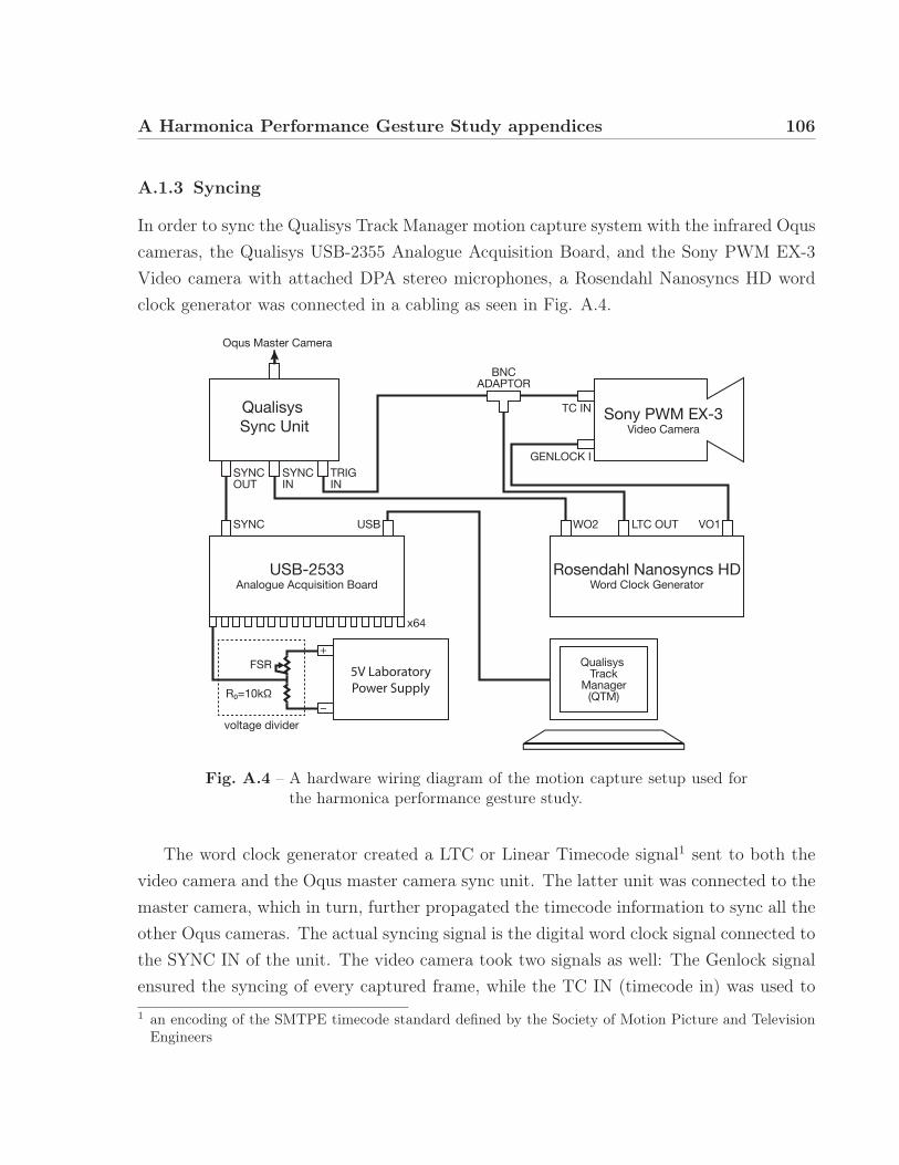
A Harmonica Performance Gesture Study appendices 106
A.1.3 Syncing
In order to sync the Qualisys Track Manager motion capture system with the infrared Oquscameras, the Qualisys USB-2355 Analogue Acquisition Board, and the Sony PWM EX-3Video camera with attached DPA stereo microphones, a Rosendahl Nanosyncs HD wordclock generator was connected in a cabling as seen in Fig. A.4.
Qualisys Sync Unit
Sony PWM EX-3Video Camera
Rosendahl Nanosyncs HDWord Clock Generator
Oqus Master Camera
Qualisys Track
Manager(QTM)
USB-2533Analogue Acquisition Board
SYNC
FSR
R
voltage divider
WO2 LTC OUT
SYNCOUT
SYNCIN
TRIGIN
TC IN
GENLOCK I
BNCADAPTOR
USB VO1
x64
5V LaboratoryPower Supply
Fig. A.4 – A hardware wiring diagram of the motion capture setup used forthe harmonica performance gesture study.
The word clock generator created a LTC or Linear Timecode signal1 sent to both thevideo camera and the Oqus master camera sync unit. The latter unit was connected to themaster camera, which in turn, further propagated the timecode information to sync all theother Oqus cameras. The actual syncing signal is the digital word clock signal connected tothe SYNC IN of the unit. The video camera took two signals as well: The Genlock signalensured the syncing of every captured frame, while the TC IN (timecode in) was used to1 an encoding of the SMTPE timecode standard defined by the Society of Motion Picture and Television
Engineers

A Harmonica Performance Gesture Study appendices 107
slave the camera to an external timecode reference signal. The acquisition of the fingerpressure data was synced by its connection to the sync out of the oqus master camera.
A.1.4 Rigid bodies
The Qualisys Track Manager software allows the specification of “rigid bodies”. Once spec-ified or acquired by capturing an exemplar object, not only is the body position in spaceavailable, but also its inclination. As this adds three degrees of freedom, this method isalso called “6DOF Tracking”.A rigid body can be defined from any structure of at least three markers whose in-betweendistance does not change. The markers should also be mounted asymmetrically on an ob-ject in order to minimize the possible errors of marker swapping by the system’s machinelearning algorithms.
In order to be able to capture the harmonica body’s inclination, a non-standard solu-tion needed to be found, as any directly attached marker would have been occluded bythe performer’s hands during performance. Therefore, an asymmetric wooden cross wasconstructed and firmly attached to the harmonica’s body by the means of metal strips andscrews. Four markers were attached to the wooden cross. The modified instrument wasplaced in the measurement realm parallel to the global coordinate axes and acquired asrigid body definition. Then, the center of gravity and pivot point were adjusted accordingto the object dimensions, in order to reflect the centre of the harmonica’s body.
The participants of the study reported the obtrusiveness of the structure to their per-formance as acceptable. One participant commented that his finger usually lays more onthe back of the top surface and that the harmonica is held deeper in his mouth, but asthe finger pressure sensor was fixed on the middle of the top surface, he had to adjust hisposture. Another participant remarked that the pressure sensor hindered him to a smalldegree in the note selection process, but only in the beginning of the study.
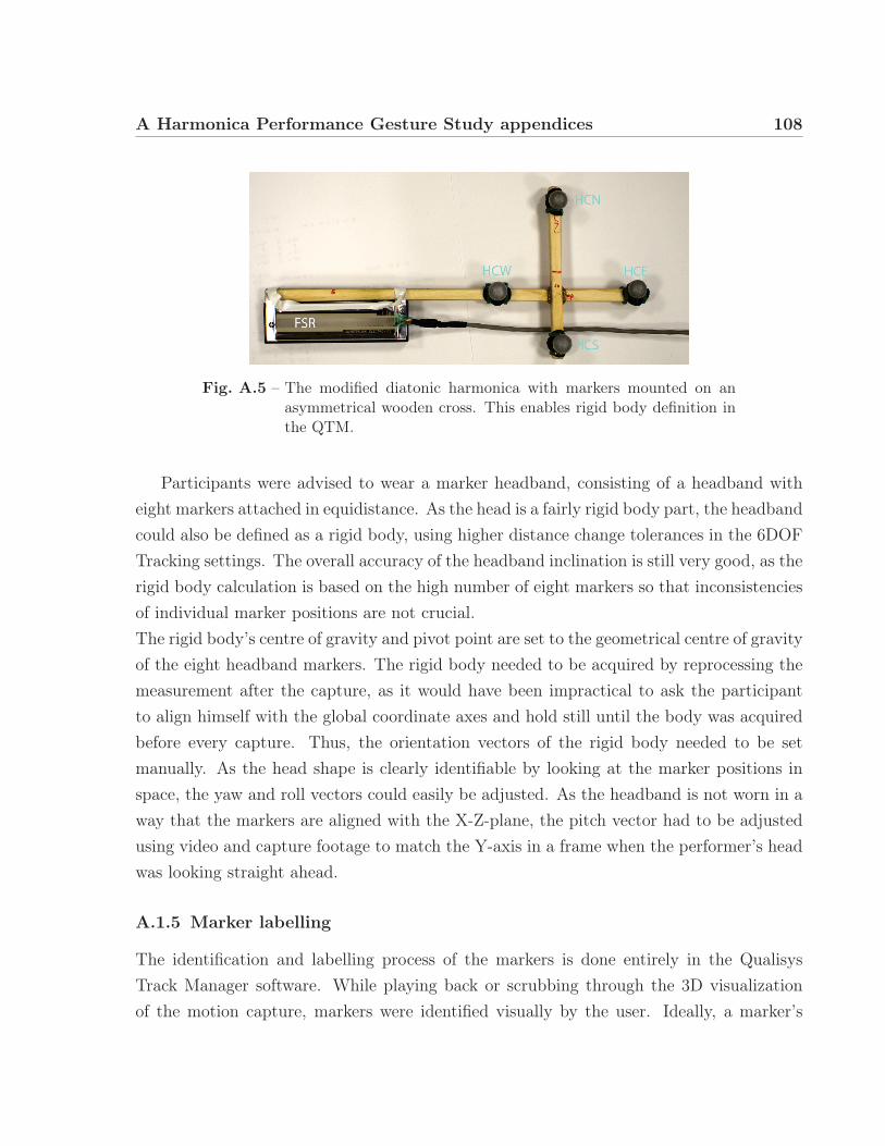
A Harmonica Performance Gesture Study appendices 108
Fig. A.5 – The modified diatonic harmonica with markers mounted on anasymmetrical wooden cross. This enables rigid body definition inthe QTM.
Participants were advised to wear a marker headband, consisting of a headband witheight markers attached in equidistance. As the head is a fairly rigid body part, the headbandcould also be defined as a rigid body, using higher distance change tolerances in the 6DOFTracking settings. The overall accuracy of the headband inclination is still very good, as therigid body calculation is based on the high number of eight markers so that inconsistenciesof individual marker positions are not crucial.The rigid body’s centre of gravity and pivot point are set to the geometrical centre of gravityof the eight headband markers. The rigid body needed to be acquired by reprocessing themeasurement after the capture, as it would have been impractical to ask the participantto align himself with the global coordinate axes and hold still until the body was acquiredbefore every capture. Thus, the orientation vectors of the rigid body needed to be setmanually. As the head shape is clearly identifiable by looking at the marker positions inspace, the yaw and roll vectors could easily be adjusted. As the headband is not worn in away that the markers are aligned with the X-Z-plane, the pitch vector had to be adjustedusing video and capture footage to match the Y-axis in a frame when the performer’s headwas looking straight ahead.
A.1.5 Marker labelling
The identification and labelling process of the markers is done entirely in the QualisysTrack Manager software. While playing back or scrubbing through the 3D visualizationof the motion capture, markers were identified visually by the user. Ideally, a marker’s
A Harmonica Performance Gesture Study appendices 109
virtual trajectory has the length of the entire measurement. However, in practice, markerssometimes get occluded, so that the trajectory is split into multiple trajectories that needto be assigned to the same marker label.Specifically with markers located very close in space to one another, such as markers at-tached to the fingers, trajectory swapping can occur. Here, the machine learning algorithmwrongly assigned part of a trajectory to an adjacent marker’s trajectory. This incorrecttrajectory needs to be split and reassigned manually.
Depending on the quality of the capture, which itself depends on the camera placement,lighting conditions, calibration quality and residual, and tracking settings such as maximumprediction error and maximum residual, the labelling of a 30-second capturing sequence cantake between 15 minutes and one hour.
Captured markers should be labelled according to the Plugin-Gait marker labelling conven-tion where applicable. If not, the labelling should still follow an easy to recognize namingconvention. For example, the right hand, second finger, uppermost segment marker waslabelled “RH2U”.
A.2 Matlab code
The Matlab scripts are available upon request and from http://www.julianvogels.de/
master-thesis/

A Harmonica Performance Gesture Study appendices 110
A.3 Questionnaire responsesQ
uest
ion
Par
tici
pant
12
34
5M
ean
(Std
)
Mai
nly
pla
yed
har
mon
ica
type
chro
mat
icdi
aton
icdi
aton
icdi
aton
icdi
aton
ic,ba
ss
Exp
erie
nce
Yea
rsof
exper
ience
1513
3020
1017
.60
(7.8
3)N
ote
Ben
din
g(1-1
0)
109
1010
109.
80(0
.45)
Ove
rblo
w/
Ove
rdra
w(1-1
0)
79
810
108.
80(1
.30)
Han
dC
uppin
g(1-1
0)
109
1010
109.
80(0
.45)
Ton
gue
Blo
ckin
g(1-1
0)
107
85
108.
00(2
.12)
Obtr
usi
venes
sof
mea
sure
men
tse
tup
acce
pta
ble
?ye
sye
sye
sye
sye
sye
s
Qual
ity
ofper
form
ance
Not
eB
endin
g(1-1
0)
1010
n/a
98
9.25
(0.9
6)H
and
Cuppin
g(1-1
0)
1010
99
109.
60(0
.55)
Ove
rdra
w/
Ove
rblo
w(1-1
0)
unkn
own
10n/
a8
109.
33(1
.15)
Roo
mTo
Mov
e(1-1
0)
unkn
own
99
88
8.50
(0.5
8)Sum
mer
tim
e(1-1
0)
unkn
own
99
87
8.25
(0.9
6)Fre
eIm
pro
visa
tion
(1-1
0)
unkn
own
88
810
8.50
(1.0
0)
Har
mon
ica-
type
DM
I
Diffi
culty
ofnot
ese
lect
ion
onsl
ide
(0
not
diffi
cult
at
all,4
very
diffi
cult
)
n/a
22
43
2.75
(0.9
6)
Obtr
usi
venes
sof
mov
emen
tre
sist
ance
(0
unobtrustiv
,4
very
obtrusiv
e)
n/a
40
40
2.00
(2.3
1)
Up/D
own
gest
ure
not
eben
dnat
ura
l?(0
very
unnatural,
4very
natural)
n/a
00
10
0.25
(0.5
0)
Nec
essi
tyof
visu
alfe
edbac
k(0
not
necessary,4
very
necessary)
n/a
21
43
2.50
(1.2
9)
Tab
leA
.1–
Har
mon
ica
perf
orm
ance
gest
ure
stud
yqu
es-
tion
nair
ere
spon
ses
(exc
erpt
wit
hout
com
-m
ents
).

111
B | Jamboxx Augmentation appendices
B.1 Arduino code
The Arduino code used to read, process, and send the additional sensor data of the JamboxxAugmentation DMI over a call and response serial connection is shown below.// REFERENCE 1
2 // Simple Proximity Sensor us ing In f r a r ed// Desc r ip t i on : Measure the d i s t ance to an ob s t a c l e us ing i n f r a r e d l i g h t emitted by IR LED and
4 // read the value with a IR photodiode . The accuracy i s not pe r f e c t , but works great// with minor p r o j e c t s .
6 // Author : Ricardo Ouvina// Date : 01/10/2012
8 // Vers ion : 1 .0
10 // REFERENCE 2/∗
12 Example f o r MCP3008 − Library f o r communicating with MCP3008 Analog to d i g i t a l conver te r .Created by Uros Petrevsk i , Nodesign . net 2013
14 Released in to the pub l i c domain .∗/
16#inc lude <MCP3008 . h>
18 #inc lude <Wire . h>#inc lude <L3G. h>
20 #inc lude <LSM303 . h>
22 // de f i n e pin connect ions#de f i n e CS_PIN 9
24 #de f i n e CLOCK_PIN 8#de f i n e MOSI_PIN 6
26 #de f i n e MISO_PIN 7#de f i n e BASE_PIN 4
28 #de f i n e NO_OF_PHTRANS 8#de f i n e FSRPIN A4
30in t ambientIR [ 8 ] ; // va r i ab l e to s t o r e the IR coming from the ambient
32 i n t obstac l e IR [ 8 ] ; // va r i ab l e to s t o r e the IR coming from the ob j e c ti n t value [ 8 ] [ 1 0 ] ; // va r i ab l e to s t o r e the IR va lues
34 i n t d i s t ance [ 8 ] ; // va r i ab l e that r ep r e s en t s the d i s t ance o f the ob j e c t to the sensor( un i t i s a s ca l ed vo l tage d i f f e r e n c e )
36i n t t imes = 4 ; // amount o f samples to the averag ing f i l t e r
38// S e r i a l communication va r i a b l e s
40 i n t s e r i a l v a l u e ; // s e r i a l input value
42 // Gyro & compass
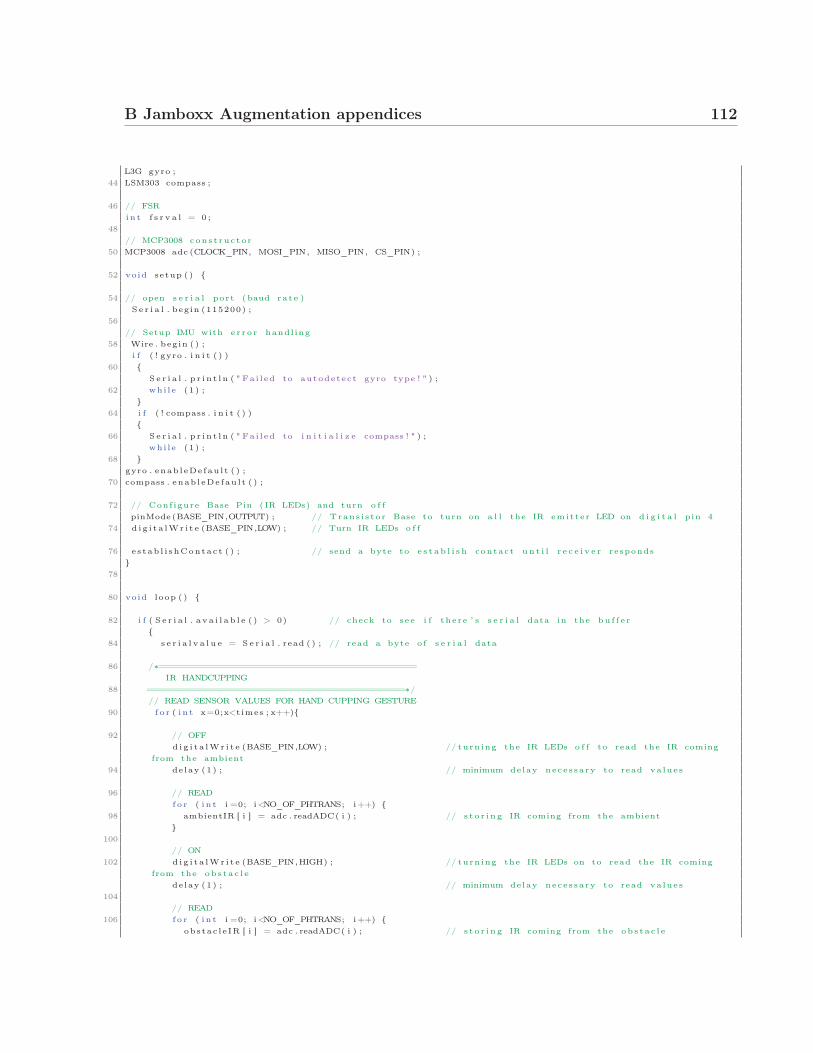
B Jamboxx Augmentation appendices 112
L3G gyro ;44 LSM303 compass ;
46 // FSRin t f s r v a l = 0 ;
48// MCP3008 cons t ruc to r
50 MCP3008 adc (CLOCK_PIN, MOSI_PIN, MISO_PIN, CS_PIN) ;
52 void setup ( ) {
54 // open s e r i a l port ( baud ra te )S e r i a l . begin (115200) ;
56// Setup IMU with e r r o r handl ing
58 Wire . begin ( ) ;i f ( ! gyro . i n i t ( ) )
60 {S e r i a l . p r i n t l n ( " Fa i l ed to autodetect gyro type ! " ) ;
62 whi le (1 ) ;}
64 i f ( ! compass . i n i t ( ) ){
66 S e r i a l . p r i n t l n ( " Fa i l ed to i n i t i a l i z e compass ! " ) ;whi le (1 ) ;
68 }gyro . enab leDe fau l t ( ) ;
70 compass . enab leDe fau l t ( ) ;
72 // Conf igure Base Pin ( IR LEDs) and turn o f fpinMode (BASE_PIN,OUTPUT) ; // Trans i s to r Base to turn on a l l the IR emit te r LED on d i g i t a l pin 4
74 d i g i t a lWr i t e (BASE_PIN,LOW) ; // Turn IR LEDs o f f
76 e s tab l i shContac t ( ) ; // send a byte to e s t a b l i s h contact un t i l r e c e i v e r responds}
78
80 void loop ( ) {
82 i f ( S e r i a l . a v a i l a b l e ( ) > 0) // check to see i f there ’ s s e r i a l data in the bu f f e r{
84 s e r i a l v a l u e = S e r i a l . read ( ) ; // read a byte o f s e r i a l data
86 /∗============================================IR HANDCUPPING
88 ============================================∗/// READ SENSOR VALUES FOR HAND CUPPING GESTURE
90 f o r ( i n t x=0;x<times ; x++){
92 // OFFd i g i t a lWr i t e (BASE_PIN,LOW) ; // turn ing the IR LEDs o f f to read the IR coming
from the ambient94 delay (1) ; // minimum delay nece s sa ry to read va lues
96 // READfo r ( i n t i =0; i<NO_OF_PHTRANS; i++) {
98 ambientIR [ i ] = adc . readADC( i ) ; // s t o r i n g IR coming from the ambient}
100// ON
102 d i g i t a lWr i t e (BASE_PIN,HIGH) ; // turn ing the IR LEDs on to read the IR comingfrom the ob s t a c l e
de lay (1) ; // minimum delay neces sa ry to read va lues104
// READ106 f o r ( i n t i =0; i<NO_OF_PHTRANS; i++) {
obstac l e IR [ i ] = adc . readADC( i ) ; // s t o r i n g IR coming from the ob s t a c l e

B Jamboxx Augmentation appendices 113
108// TAKE DIFFERENCE
110 value [ i ] [ x ] = ambientIR [ i ]− obstac l e IR [ i ] ; // c a l c . IR va l . changes , s t o r e f o r average}
112 }
114 f o r ( i n t x=0;x<times ; x++){ // c a l c u l a t i n g the average based on the " accuracy "f o r ( i n t i =0; i<NO_OF_PHTRANS; i++) {
116 d i s t ance [ i ]+=value [ i ] [ x ] ;}
118 }f o r ( i n t i =0; i<NO_OF_PHTRANS; i++) {
120 d i s t ance [ i ] = d i s tance [ i ] / t imes ; // f i n a l mean valueS e r i a l . p r i n t ( d i s t ance [ i ] ) ;
122 S e r i a l . p r i n t ( " " ) ;}
124/∗============================================
126 FORCE SENSING RESISTOR============================================∗/
128 f s r v a l = analogRead (FSRPIN) ;S e r i a l . p r i n t ( f s r v a l ) ;
130 S e r i a l . p r i n t ( " " ) ;
132 /∗============================================INERTIAL MEASUREMENT UNIT
134 ============================================∗/readGyro ( ) ;
136 S e r i a l . p r i n t l n ( ) ;
138 }}
140void e s tab l i shContac t ( ) {
142 whi le ( S e r i a l . a v a i l a b l e ( ) <= 0) {S e r i a l . p r i n t l n ( "whatevs" ) ; // send an i n i t i a l s t r i n g
144 de lay (300) ;}
146 }
148void readGyro ( ) {
150 gyro . read ( ) ;compass . read ( ) ;
152// X
154 S e r i a l . p r i n t ( ( ( i n t ) gyro . g . x ) ) ;S e r i a l . p r i n t ( " " ) ;
156 // YS e r i a l . p r i n t ( ( ( i n t ) gyro . g . y ) ) ;
158 S e r i a l . p r i n t ( " " ) ;// Z
160 S e r i a l . p r i n t ( ( ( i n t ) gyro . g . z ) ) ;S e r i a l . p r i n t ( " " ) ;
162 // YawS e r i a l . p r i n t ( ( ( i n t ) compass . a . x ) ) ;
164 S e r i a l . p r i n t ( " " ) ;// Pitch
166 S e r i a l . p r i n t ( ( ( i n t ) compass . a . y ) ) ;S e r i a l . p r i n t ( " " ) ;
168 // Rol lS e r i a l . p r i n t ( ( ( i n t ) compass . a . z ) ) ;
170 S e r i a l . p r i n t ( " " ) ;
172 }

B Jamboxx Augmentation appendices 114
B.2 Max patch
The Max/MSP patch is available upon request and from http://www.julianvogels.de/
master-thesis/.
115
Patent references
Anderson, Axel William. 1908. Harmonica. US904914 A, filed November 24, 1908.
Antaki, James F. 2001. Harmonica having reed vibration conversion capability and associ-ated retrofitting method US6326532 B1, filed December 4, 2001.
Arai, Yoneaki. 1984. Elektronische Harmonika, sowie Eingabevorrichtung hierfür DE3407655A1, filed September 6, 1984.
Bibus, Hans. 1949. Mouth organ US2478963 A, filed August 16, 1949.
. 1958. Chromatic mouthorgan US2827818 A, filed March 25, 1958.
Blobel, Harald, Walter Muller, and Urs P. Studer. 1983. Operating apparatus used atan electronic instrument provided with at least one synthesizer US4385541 A, filedMay 31, 1983.
Brown, Carl E. 1899. Musical instrument. US627569 A, filed June 27, 1899.
Hillairet, Claude A., Jean H. M. Lecadre, and Boulevard Richard Wallace. 1970. Electronicharmonica with individual reed pickups and tone generator system US3516320 A, filedJune 23, 1970.
Kondo, Yoshio. 1997. Harmonica Type Electronic Musical Instrument JPH09281960 (A),filed October 31, 1997.
Li, Zuge, and Zuping Li. 1990. Multiple Tone Colour Changeable Tonal Modification Elec-tronic Harmonica CN2064091 (U), filed October 17, 1990.
Mast, Kurt. 1953. Harmonica US2646712 A, filed July 28, 1953.
Matsuzaki, Akio. 1986. Input device for an electronic musical instrument US4619175 A,filed October 28, 1986.
Mölders, Franz. 1980. Mundharmonika DE2906817 A1, filed September 4, 1980.
Naumann, Klaus. 1979. Mouthpieces and electronic musical instruments for use therewithGB1547867 (A), filed June 27, 1979.

Patent references 116
Read, Wayne Richard, and Deidre Hebert. 2013. Multi Channel Digital Wind InstrumentUS20130192446 A1, filed August 1, 2013.
Robert, Michel François. 1982. Clavier électromécanique à vent FR2486286 (A1), filedJanuary 8, 1982.
Schille, Ron. 1991. Electronic harmonica for controlling sound synthesizers US4984499 A,filed January 15, 1991.
Whalen, David S., James J. Luther, and Michael C. DiCesare. 2011. Adaptive midi windcontroller device US20110025455 A1, filed February 3, 2011.
Wheaton, James A. 1993. Polyphonic breath controlled electronic musical instrument US5245130A, filed September 14, 1993.
Wilken, Erwin. 1965. Mundorgel DE1191213 B, filed April 15, 1965.
Workman, Ernest Robert. 1949. Musical instrument US2475168 A, filed July 5, 1949.
Yongcai, Sun. 1998. Electronic mouth organ CN2282245 (Y), filed May 20, 1998.
Zhang, Pengcheng, and Haitao Zhang. 1993. Electronic mouth-organ CN2146765 (Y), filedNovember 17, 1993.
Ziegler, Arwed. 1989. Elektronische Mundharmonika DE3911836 A1, filed December 7,1989.

117
Other references
Ahrens, Christian. 2002. Zur Frühgeschichte der Instrumente mit Durchschlagzungen inEuropa. Harmonium und Handharmonika, Michaelsteiner Konferenzberichte, 62:31–50. Accessed May 5, 2014.
Antaki, James F. 2014. Research. TURBOHARP Harmonicas. Accessed May 26. http://www.turboharp.com/research.
Antaki, James F., Henry T. Bahnson, Quinter C. Beery, and G. Burgeen. 2002. Physiology& Phonetics of the Diatonic Harmonica, pp 3 and 15. Pittsburgh, PA.
Austin, S.F. 2007. Jaw Opening in Novice and Experienced Classically Trained Singers.Journal of Voice 21 (1): 72–79. issn: 0892-1997.
Bahnson, Henry T., James F. Antaki, and Quinter C. Beery. 1998. Acoustical and physicaldynamics of the diatonic harmonica. The Journal of the Acoustical Society of America103:2134. Accessed September 27, 2013.
Baker, Steve. 1999. The Harp Handbook. Expanded 3rd Edition. Wise Publications. Ac-cessed May 14, 2014.
. 2014. The Harp Handbook. Accessed May 14, 2014. http://www.stevebaker.de/the_harp_handbook_en_73.html.
Baym, Nancy, Jonathan Sterne, Georgia Born, Andrew Dubber, Blake Durham, TarletonGillespie, Mack Hagood, et al. 2014. A Manifesto for Music Technologists. AccessedMay 15, 2014. http://www.musictechifesto.org/.
Benade, Arthur H. 2012. Fundamentals of Musical Acoustics. Second, Revised Edition.Courier Dover Publications, June 11. isbn: 9780486150710.
Berghoff, Hartmut. 2001. Marketing Diversity: the Making of a Global Consumer Product— Hohner’s Harmonicas, 1857–1930. Enterprise and Society 2, no. 2 (June 1): 338–372. issn: 1467-2227, 1467-2235, accessed May 5, 2014.

Other references 118
Bevilacqua, Frédéric, Rémy Müller, and Norbert Schnell. 2005. MnM: a Max/MSP mappingtoolbox. In Proceedings of the 2005 conference on new interfaces for musical expression(NIME 2005), 85–88. Vancouver, Canada. Accessed June 19, 2014.
Birnbaum, David, Rebecca Fiebrink, Joseph Malloch, and Marcelo M. Wanderley. 2005.Towards a dimension space for musical devices. In Proceedings of the 2005 conferenceon new interfaces for musical expression, 192–195. Accessed April 17, 2014.
Brum Medeiros, Carolina, and Marcelo M. Wanderley. 2014. A Comprehensive Review ofSensors and Instrumentation Methods in Devices for Musical Expression. Sensors 14,no. 8 (July 25): 13556–13591. Accessed July 28, 2014.
Burger, Birgitta, and Petri Toiviainen. 2013. MoCap Toolbox-A Matlab toolbox for compu-tational analysis of movement data. In Proceedings of the sound and music computingconference 2013 (SMC 2013). Stockholm, Sweden: Logos Verlag Berlin. isbn: 978-3-8325-3472-1, accessed February 7, 2014.
Cadoz, C., and Marcelo M. Wanderley. 2000. Gesture-Music. In Trends in gestural control ofmusic, edited by Marcelo Wanderley and Marc Battier, 71–94. Paris, France: IRCAM.
Chadabe, Joel. 2001. The Electronic Century Part I: Beginnings. Accessed April 8, 2014.http://www.emusician.com/gear/0769/the- electronic- century- part- i-beginnings/143739.
Cook, Perry. 2001. Principles for Designing Computer Music Controllers. In Proceedings ofthe 2001 conference on new interfaces for musical expression, 1–4. Accessed May 13,2014.
Cottingham, James. 2011. Acoustics of free-reed instruments. Physics Today 64 (3): 44–48.Accessed May 28, 2013.
. 2013. Modes of reed vibration and transient phenomena in free reed instruments.In Proceedings of the international congress on acoustics (ICA2013), vol. 19. Montreal,Canada, June.
Da Silva, Andrey R., Marcelo M. Wanderley, and Gary Scavone. 2005. On the use of fluteair jet as a musical control variable. In Proceedings of the 2005 conference on newinterfaces for musical expression, 105–108. Accessed July 29, 2014.
Dalmont, J.-P. 2001. Acoustic Impedance Measurement, Part I: A Review. Journal of Soundand Vibration 243, no. 3 (June 7): 427–439. issn: 0022-460X, accessed October 15,2013.
De Cheveigné, Alain, and Hideki Kawahara. 2002. YIN, a fundamental frequency estimatorfor speech and music. The Journal of the Acoustical Society of America 111 (4): 1917–1930. Accessed June 17, 2014.

Other references 119
Debut, Vincent, and Laurent Millot. 2001. Time domain simulation of the diatonic harmon-ica. In Workshop on current research direction in computer music: mosart europeanprogram, barcelona, 143–146. Accessed May 12, 2014.
DiCesare, Michael C. 2012. Jamboxx: A Way For Everyone To Make Music. Kickstarter.Accessed November 26, 2013. http://www.kickstarter.com/projects/203730329/jamboxx-a-way-for-everyone-to-make-music.
Egbert, Peter R., Lewis K. Shin, David Barrett, Thomas Rossing, and Andrew B. Holbrook.2013. Real-tiime magnetic resonance imaging of the upper airways during harmon-ica pitch bends. In Proceedings of the international congress on acoustics (ICA2013),19:035075. Montreal, Canada: ASA. Accessed September 27, 2013.
Epps, J., J. R. Smith, and J. Wolfe. 1997. A novel instrument to measure acoustic resonancesof the vocal tract during phonation. Measurement Science and Technology 8, no. 10(October 1): 1112. issn: 0957-0233, accessed October 15, 2013.
Eyers, Tony. 2011. The Asian Harmonica Scene. Accessed May 6, 2014. http://www.tremoloharmonica.com/asian-harmonica-scene.shtml.
Glover, Tony. 1965. Blues Harp. New York, NY, USA: Oak Publications. isbn: 0.8256.0018.9.
Grey, John M., and John W. Gordon. 1978. Perceptual effects of spectral modifications onmusical timbres. The Journal of the Acoustical Society of America 63, no. 5 (May 1):1493–1500. issn: 0001-4966, accessed June 26, 2014.
Hikichi, Takafumi, Naotoshi Osaka, and Fumitada Itakura. 2003. Time-domain simulationof sound production of the sho. The Journal of the Acoustical Society of America 113,no. 2 (February 1): 1092–1101. issn: 0001-4966, accessed May 12, 2014.
HOHNER Musikinstrumente GmbH & Co, KG. 2014. World Harmonica Festival 2013.Accessed May 13, 2014. http://ca.playhohner.com/news/world- harmonica-festival-2013/.
Hunt, Andy, and Ross Kirk. 2000. Mapping strategies for musical performance. Trends inGestural Control of Music 21:2000. Accessed June 2, 2014.
Hunt, Andy, and Marcelo M. Wanderley. 2002. Mapping performer parameters to synthesisengines. Organised Sound 7 (2): 97–108.
Jamboxx Music. 2014a. Jamboxx Midi Controllers. YOUTUBE. January 18. AccessedFebruary 1, 2014. https://www.youtube.com/watch?v=5cYLTi8gI-s.
. 2014b. Jamboxx Midi Controllers - Switches. YOUTUBE. February 23. AccessedMay 26, 2014. https://www.youtube.com/watch?v=NmESKEaksAs.

Other references 120
Johnston, Robert B. 1987. Pitch control in harmonica playing. Acoustics Australia 15:69–75. Accessed September 27, 2013.
Kob, Malte, and Christiane Neuschaefer-Rube. 2002. A method for measurement of the vo-cal tract impedance at the mouth. Medical Engineering & Physics 24, no. 7 (Septem-ber): 467–471. issn: 1350-4533, accessed October 7, 2013.
Krampert, Peter. 1998. The encyclopedia of the harmonica. Tatanka Pub.
Laubier, Serge de. 1998. The Meta-Instrument. Computer Music Journal 22, no. 1 (April 1):25–29. Accessed May 30, 2014.
Licht, Michael S. 1980. Harmonica Magic: Virtuoso Display in American Folk Music. Eth-nomusicology 24, no. 2 (May 1): 211–221. issn: 0014-1836, accessed November 18,2013.
Maeda, John. 2006. The Laws of Simplicity. MIT press. Accessed August 4, 2014.
Malloch, Joseph, Stephen Sinclair, and Marcelo M. Wanderley. 2007. From controller tosound: Tools for collaborative development of digital musical instruments. In Pro-ceedings of the 2007 international computer music conference, copenhagen, denmark.Accessed June 4, 2014.
. 2013. Libmapper: (a Library for Connecting Things). In CHI ’13 extended abstractson human factors in computing systems, 3087–3090. CHI EA ’13. New York, NY, USA:ACM. isbn: 978-1-4503-1952-2, accessed June 4, 2014.
Malloch, Joseph, and Marcelo M. Wanderley. 2007. The T-stick: From musical interface tomusical instrument. In Proceedings of the 7th international conference on new inter-faces for musical expression, 66–70. ACM. Accessed May 30, 2014.
Meisel, Fritz. 1981. Geschichte der Mundharmonika. Musikblatt, no. 4:39.
Millioniser. 1984. Millioniser 2000 Instruction Manual.
millioniser2000. 2009. Millioniser 2000 Promo Video Rock Erickson London, England 1983.July 18. Accessed May 7, 2014. https://www.youtube.com/watch?v=XRPI_fD0iKQ&feature=youtube_gdata_player.
Millot, L., C.h. Cuesta, and C. Valette. 2001. Experimental Results when Playing Chro-matically on a Diatonic Harmonica. Acta Acustica united with Acustica 87 (2): 262–270.
Millot, Laurent. 1999. Étude des instabilités des valves: Application à l’harmonica dia-tonique. doctoral dissertation, Université Paris 6.
Other references 121
Millot, Laurent. 2011. Chromatical playing on diatonic harmonica: from physical modelingto sound synthesis. The Journal of the Acoustical Society of America 130 (4): 2342.issn: 00014966, accessed May 12, 2014.
Millot, Laurent, and Clément Baumann. 2007. A Proposal for a Minimal Model of FreeReeds. Acta Acustica united with Acustica 93 (1): 122–144.
Miranda, Eduardo Reck, and Marcelo M. Wanderley. 2006. New Digital Musical Instru-ments: Control and Interaction Beyond the Keyboard. Vol. 21. AR Editions, Inc. Ac-cessed April 26, 2014.
Missin, Pat. 2012. Books, CDs and Videos of Uncommon Interest. Accessed May 14, 2014.http://www.patmissin.com/uncommon/books.html.
Paradiso, Joseph A., and Neil Gershenfeld. 1997. Musical Applications of Electric FieldSensing. Computer Music Journal 21, no. 2 (July 1): 69–89. Accessed July 28, 2014.
Pascal, M. 1997. Le studio instrumental: les donnes d’une virtuosite a l’interieur meme duson. In Colloque les nouveaux gestes de la musique.
Place, Tim, and Trond Lossius. 2006. Jamoma: A modular standard for structuring patchesin Max. In Proceedings, international computer music conference, new orleans. Ac-cessed June 19, 2014.
Read, Wayne Richard. 2012. Xharp MIDI-Multi-Breath Controller Electronic Harmonica.Kickstarter. Accessed November 26, 2013. http://www.kickstarter.com/projects/936712270/xharp-midi-multi-breath-controller.
Ryan, Joel. 1992. Effort and expression. In Proceedings of the international computer musicconference, 414–414. International Computer Music Association.
Schwörer-Kohl, Gretel. 1997. Mundorgel. Die Musik in Geschichte und Gegenwart 6.
Sloetjes, Han, and Peter Wittenburg. 2008. Annotation by Category: ELAN and ISO DCR.In LREC. Accessed February 7, 2014.
Sundberg, Johan, and Jörgen Skoog. 1997. Dependence of Jaw Opening on Pitch and Vowelin Singers. Journal of Voice 11 (3): 301–306. Accessed April 18, 2014.
Tarabella, Leonello. 2000. Gestural and Visual Approaches to Performance. Trends in Ges-tural Control of Music CD-ROM, IRCAM, Paris:604–615. Accessed August 11, 2014.
Tarnopolsky, A. Z., N. H. Fletcher, and J. C. S. Lai. 2000. Oscillating reed valves—anexperimental study. The Journal of the Acoustical Society of America 108 (1): 400–406. Accessed May 12, 2014.
Other references 122
Vertegaal, Roel, Tamas Ungvary, and Michael Kieslinger. 1996. Towards a Musician’s Cock-pit: Transducers, Feedback and Musical Function. In Proceedings of the internationalcomputer music conference, 308–311. International Computer Music Association. Ac-cessed April 24, 2014.
Wanderley, Marcelo M. 2002. Quantitative analysis of non-obvious performer gestures. InGesture and sign language in human-computer interaction, 241–253. Springer. AccessedJune 6, 2014.
Wanderley, Marcelo M., and Philippe Depalle. 2004. Gestural Control of Sound Synthesis.Proceedings of the IEEE 92 (4): 632–644. Accessed April 24, 2014.
Wanderley, Marcelo M., and Nicola Orio. 2002. Evaluation of Input Devices for MusicalExpression: Borrowing Tools from HCI. Computer Music Journal 26 (3): 62–76.
Wanderley, Marcelo M., Bradley W. Vines, Neil Middleton, Cory McKay, and WesleyHatch. 2005. The musical significance of clarinetists’ ancillary gestures: An explorationof the field. Journal of New Music Research 34 (1): 97–113. Accessed June 4, 2014.
Wessel, David, and Matthew Wright. 2002. Problems and Prospects for Intimate MusicalControl of Computers. Computer Music Journal 26 (3): 11–22. Accessed May 13, 2014.