havells spn 100a type a db ( ) instruction manual spn 100a...
TRANSCRIPT
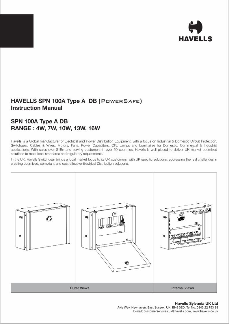
HAVELLS SPN 100A Type A DB ( ) Instruction Manual
SPN 100A Type A DBRANGE : 4W, 7W, 10W, 13W, 16W
Havells is a Global manufacturer of Electrical and Power Distribution Equipment, with a focus on Industrial & Domestic Circuit Protection, Switchgear, Cables & Wires, Motors, Fans, Power Capacitors, CFL Lamps and Luminaires for Domestic, Commercial & Industrial applications. With sales over $1Bn and serving customers in over 50 countries, Havells is well placed to deliver UK market optimized solutions to meet local standards and regulatory requirements.
In the UK, Havells Switchgear brings a local market focus to its UK customers, with UK specific solutions, addressing the real challenges in creating optimized, compliant and cost effective Electrical Distribution solutions.
Outer Views Internal Views
Havells Sylvania UK LtdAvis Way, Newhaven, East Sussex, UK. BN9 0ED, Tel No: 0843 22 753 88
E-mail: [email protected], www.havells.co.uk
1 5
2
3
4
7
8
9
6
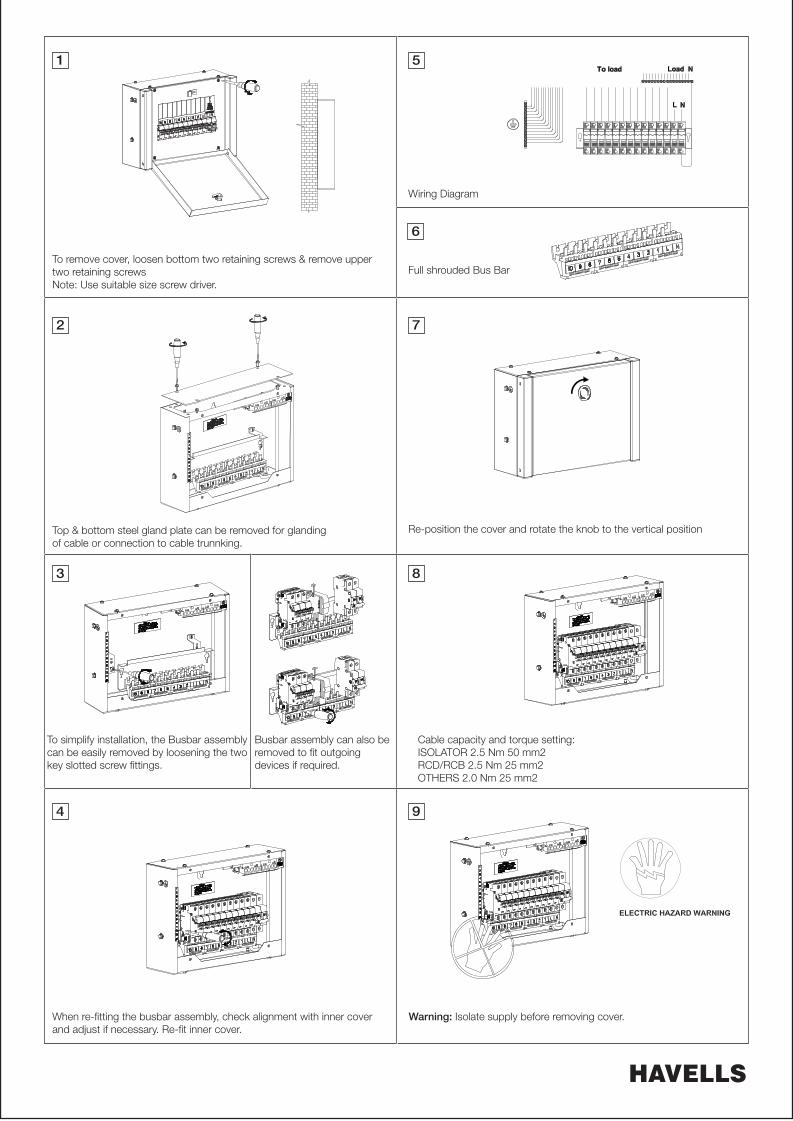
Full shrouded Bus Bar
Wiring Diagram
To remove cover, loosen bottom two retaining screws & remove uppertwo retaining screwsNote: Use suitable size screw driver.
Top & bottom steel gland plate can be removed for glandingof cable or connection to cable trunnking.
Re-position the cover and rotate the knob to the vertical position
When re-fitting the busbar assembly, check alignment with inner coverand adjust if necessary. Re-fit inner cover.
Warning: Isolate supply before removing cover.
Cable capacity and torque setting:ISOLATOR 2.5 Nm 50 mm2RCD/RCB 2.5 Nm 25 mm2OTHERS 2.0 Nm 25 mm2
To simplify installation, the Busbar assemblycan be easily removed by loosening the twokey slotted screw fittings.
Busbar assembly can also be removed to fit outgoingdevices if required.