hawker beechcraft
TRANSCRIPT

7/29/2019 hawker beechcraft
http://slidepdf.com/reader/full/hawker-beechcraft 1/24
Page 9-1Pilot’s Operating Manual
Original Issue: Feb, 2002
Pro Line 21
Section - IIISYSTEMS DESCRIPTION
Sub-section 9ELECTRICAL POWER
Table of Contents
Page
GENERAL......................................................................................................9-3
CONTROLS and INDICATIONS....................................................................9-3
EXTERNAL POWER ...................................................................................9-3
BATTERY SUPPLIES..................................................................................9-4
AMMETERS ................................................................................................9-4
Figure 1 - DC Electrical System - De-energized......................................9-5
VOLTMETER...............................................................................................9-6EXT BATT CHG ON/OFF switch .................................................................9-6
Figure 2 - Ground Power Connected withExternal Battery Charge Switch ON........................................9-7
BATT EMERG-ON-OFF switch ...................................................................9-8
BATT ISOLATE BATT 1-NORM-BATT 2 switch..........................................9-9
Figure 3 - Battery Switch ON.................................................................9-10
BUS TIE CLOSE-OPEN switch .................................................................9-11
GEN 1 AND GEN 2 CLOSE-TRIP switch ..................................................9-11
Figure 4 - Normal Flight Conditions.......................................................9-12
ENGINE START USING EXTERNAL POWER............................................9-13
ABORT START..........................................................................................9-13
Figure 5 - Internal Start with No. 2 Engine Selected .............................9-14
ENGINE START USING BATTERY POWER..............................................9-15
WITH A GENERATOR ON LINE...............................................................9-15
DC POWER GENERATION ......................................................................9-15
SINGLE GENERATOR FAILURE..............................................................9-16
DOUBLE GENERATOR FAILURE............................................................9-16
Figure 6 - Single Generator Failure .......................................................9-17
Figure 7 - Double Generator Failure......................................................9-18
APU GENERATOR (if APU installed) ........................................................9-19
OVERVOLTAGE PROTECTION...............................................................9-19Figure 8 - APU (if installed) Generator On-Line ....................................9-19
AC POWER..................................................................................................9-20
CONTROLS and INDICATIONS................................................................9-20
STATIC INVERTERS ................................................................................9-21
Starting No. 1 Inverter .............................................................................9-21
Starting No. 2 Inverter .............................................................................9-21
Failure Of A Main Inverter .......................................................................9-21
Failure Of Both Main Inverters ................................................................ 9-21

7/29/2019 hawker beechcraft
http://slidepdf.com/reader/full/hawker-beechcraft 2/24
Page 9-2 Pilot’s Operating Manual
Original Issue: Feb, 2002
Sub-section 9
ELECTRICAL POWER
Hawker 800XP Pro Line 21Section III - SYSTEMS DESCRIPTION
Page
AC POWER DISTRIBUTION .................................................................... 9-22
Figure 8 - Inverter System Busbars - Simplified.................................... 9-22
ALTERNATOR POWER SUPPLY ............................................................ 9-23

7/29/2019 hawker beechcraft
http://slidepdf.com/reader/full/hawker-beechcraft 3/24
Page 9-3Pilot’s Operating Manual
Revision A1: Nov, 2002
Sub-section 9
ELECTRICAL POWER
Hawker 800XP Pro Line 21
Section III - SYSTEMS DESCRIPTION
GENERAL
The airplane utilizes both DC and AC systems with emergency systems available for certain instrumentand avionics requirements. The 28 VDC system uses a tied-busbar powered from engine driven starter/generators and backed-up by batteries. A third starter/generator driven from the Auxiliary Power Unit (ifinstalled) is also available.
Power from the engine-driven generators and the APU generator is distributed by two essential busbarsystems, PS1 and PS2. In normal flight conditions the two PS busbars are tied in parallel by a bus tiecontrolled by a BUS TIE switch, selected to CLOSE. Each generator circuit contains a voltage regulatorwhich stabilizes the busbars at 28 ± 0.75 VDC. With a generator on line, selecting the BUS TIE switchto CLOSE connects the two PS busbars in parallel. A start busbar links the start power source (eitherthe ground supply contactor or the internal start contactor) with the individual engine 1 and 2 startcontactor or the APU start contactor. AC power is supplied through two systems, one using inverters,the other engine driven alternators.
CONTROLS and INDICATIONS
EXTERNAL POWER
A standard three pin 28 VDC external power receptacle is located at the right rear fuselage. For externalstarts, a ground power unit capable of supplying 28 VDC with a minimum output of 42 kW (short termcapability of 28 VDC x 1500 AMPS) and having a limiter operating at 1100 AMPS must be used.
External power is connected to the airplane busbars through a ground power contactor. Contactoroperation is controlled by the EXT PWR switch supplied from the third pin of the external powerreceptacle. With external power available and the EXT PWR switch ON and the EXT BATT CHG switchOFF, the No. 1 and No. 2 batteries are disconnected from the busbars. Selecting the BATT switch to ONhas no effect.
OFF
ONEXT PWR
Overhead Roof Panel
External Ground Power Receptacle
7/29/2019 hawker beechcraft
http://slidepdf.com/reader/full/hawker-beechcraft 4/24
Page 9-4 Pilot’s Operating Manual
Revision A1: Nov, 2002
Sub-section 9
ELECTRICAL POWER
Hawker 800XP Pro Line 21Section III - SYSTEMS DESCRIPTION
CAUTION: NO. 1 BATTERY MAY BE EXCESSIVELY DISCHARGED AND DAMAGED IF THE ROOF
SWITCH ON PANEL DA AND THE ENTRY LIGHT SWITCH ON THE FORWARD CABIN
BULKHEAD ARE LEFT ON FOR LONG PERIODS WHILE EXTERNAL POWER IS APPLIED.
THE VESTIBULE ROOF LIGHT AND THE ENTRY LIGHT ARE CONNECTED VIA THEIR
SWITCHES DIRECTLY TO NO. 1 BATTERY AND WILL COME ON IRRESPECTIVE OF THE
POSITION OF THE EXT PWR, EXT BATT CHG OR BATT SWITCHES.
With the EXT BATT CHG switch ON, each battery is connected to its associated busbar (PS1 and PS2)and charged from the external power supply. The external power cannot be paralleled with the airplanegenerators.
BATTERY SUPPLIES
Two 24 VDC, 28 ampere-hour sealed lead acid main batteries, No. 1 and No. 2, are located in the rearequipment bay. These batteries provide internal power for engine starting and also maintain essentialservices in the event of a double generator failure.
NOTE: When the correct emergency drill is carried out together with prompt shedding of non- essential loads, the batteries can maintain essential services for a minimum of 60 minutes.
In addition to the main battery supplies, three 24 VDC 4 ampere-hour sealed lead acid batteries Nos.3, 4 and 5 are located in the rear equipment bay. These batteries provide electrical power for theemergency lighting and essential services during emergency conditions.
Also, one 24 VDC 4 ampere-hour sealed lead acid battery No. 6 is located in the avionics shelf of theaft cabin. This battery provides electrical power to the Electronic Standby Instrument System (ESIS) inthe event of a double generator failure and the output of the PE busbar being less than 21 VDC.
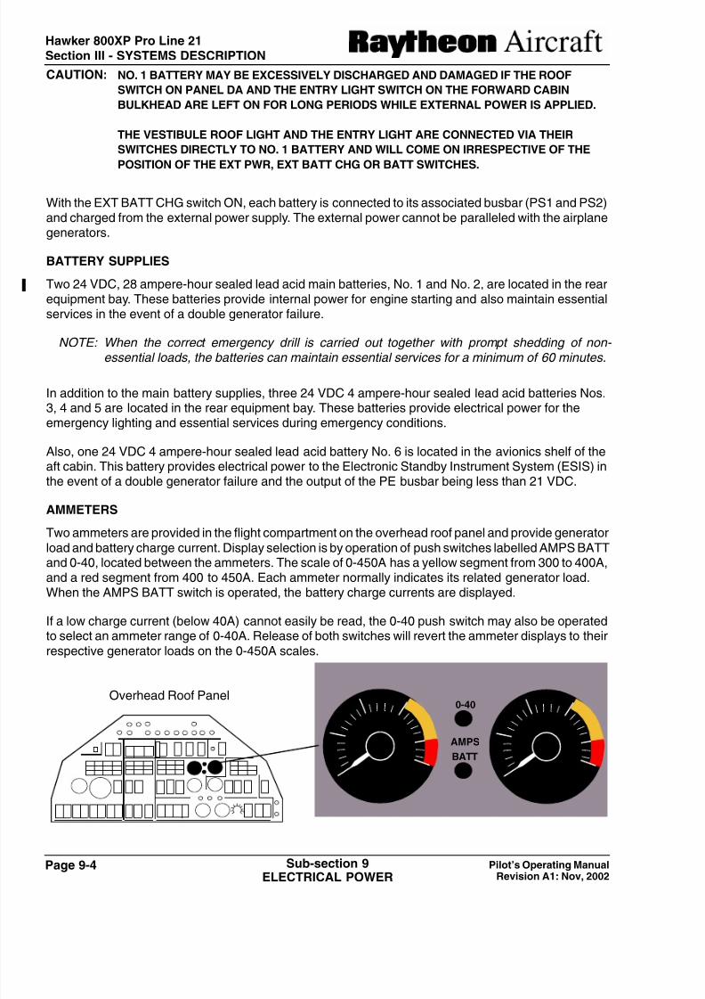
AMMETERS
Two ammeters are provided in the flight compartment on the overhead roof panel and provide generatorload and battery charge current. Display selection is by operation of push switches labelled AMPS BATTand 0-40, located between the ammeters. The scale of 0-450A has a yellow segment from 300 to 400A,and a red segment from 400 to 450A. Each ammeter normally indicates its related generator load.When the AMPS BATT switch is operated, the battery charge currents are displayed.
If a low charge current (below 40A) cannot easily be read, the 0-40 push switch may also be operatedto select an ammeter range of 0-40A. Release of both switches will revert the ammeter displays to theirrespective generator loads on the 0-450A scales.
Overhead Roof Panel 0-40
AMPS
BATT
1111100
200300
400
DC
A
1111100
200300
400
DC
A

7/29/2019 hawker beechcraft
http://slidepdf.com/reader/full/hawker-beechcraft 5/24
Page 9-5Pilot’s Operating Manual
Revision A1: Nov, 2002
Sub-section 9
ELECTRICAL POWER
Hawker 800XP Pro Line 21
Section III - SYSTEMS DESCRIPTION
P W R O N
P U S H F O R
A B O R T
O P E R A T I N G
A P U
S T A R T E R
G E N
N o . 1
S T A R T E R
G E N
O P E R A T I N G
G E N S H U N T 2
G E N
S H U N T 1
A P U G E N
E X T E R N A L P O W E R
S
T A R T E R B U S B A R
P E B U S B A R
B A T T 2
B A T T
1
P E 2
N o . 2
S T A R T E R
G E N
P S 1
B U S B A R
P S 2 B U S B A R
G R O U N D P O W E R
C O N T A C T O R
B A T T
S H U N T
1
B A T T
S H U N T
2
E N G 2
E N G 1
S H U N T
I N T S T A R T
C O N T A C T O R
A P U G E N
C O N T A C T O R
A P U S T A R T
C O N T A C T O R
G E N
L I N E
C O N
T A C T O R 1
G
E N L I N E
C O N T A C T O R 2
B U S T I E
C O N T A C T O R
B A T T 2
C O N T A C T O R
B A T T 1
C O N T A C T O R
E M E R G E N C Y
C O N T A C T O R S
1
2
P
O W E R
D
I O D E
P O W E R
D I O D E
P O W E R
D I O D E
P O W E R
D I O D E
F U S E
F U S E
F U S E
A P U
G E N
F A I L
G E N
2
F A I L
B A T T 2
C N T C T R
B U S
T I E
O P E N
B A T T 1
C N T C T R
G E N
1
F A I L
Figure 1DC Electrical System De-energized

7/29/2019 hawker beechcraft
http://slidepdf.com/reader/full/hawker-beechcraft 6/24
Page 9-6 Pilot’s Operating Manual
Revision A1: Nov, 2002
Sub-section 9
ELECTRICAL POWER
Hawker 800XP Pro Line 21Section III - SYSTEMS DESCRIPTION
VOLTMETER
A 0-40V voltmeter and selector switches are provided in the flight compartment on the overhead roofpanel. The voltmeter scale has a red segment between 32V and 40V. The voltmeter may display, byselection on the switches, the voltage of the batteries (1 thru 6), busbars PE, PS1 or PS2. The positionson the switches are labelled B1, PS1, PE, PS2, B2, XFER and B3, B4, B5, B6, OFF.
EXT BATT CHG ON/OFF switch
The No. 1 battery is charged from the PS1 busbar, and No. 2 battery is charged from the PS2.
As a generator comes on-line, the associated battery contactor closes automatically and the chargebegins. The batteries may also be charged from an external power source by selecting the EXT BATTCHG switch to ON.
Rates of charges should be monitored on the generator ammeters during external charging and whenthe charge rate drops to less than 5 AMPS the EXT BATT CHG switch should be selected OFF.
During external charging, if the power supply voltage rises or falls beyond preset limits, the charging willautomatically terminate.
Overhead Roof Panel
111110
20
30
40
DC
v
PS1
PE
PS2
B1 B2
DC VOLTS
B4
B5
B6
B3 OFF
XFER
OFF
ONEXT BATT CHG
Overhead Roof Panel

7/29/2019 hawker beechcraft
http://slidepdf.com/reader/full/hawker-beechcraft 7/24
Page 9-7Pilot’s Operating Manual
Revision A1: Nov, 2002
Sub-section 9
ELECTRICAL POWER
Hawker 800XP Pro Line 21
Section III - SYSTEMS DESCRIPTION
+ +-
STARTER BUSBAR
PS2 BUSBARPS1 BUSBAR
No. 1STARTER
GEN
No. 2
STARTER
GEN
APU
STARTER
GEN
APU START
GEN LINE
CONTACTOR
No. 2
GEN LINECONTACTOR
No. 1
PE BUSBAR
BATT 1 BATT 2
INTERNAL START
CONTACTOR
EMERGENCY CONTACTORS PE 2
GEN SHUNTNo. 1
GEN SHUNT
No. 2
APU GENSHUNT
EXTERNAL POWERCONTACTOR
TO PS2(a) and PS2(b)
BUSBARS
TO PS1(a) and PS1(b)
BUSBARS
OPERATING
ENG 2
GEN 2
FAIL
BUS TIEOPEN
GEN 1
FAIL
PWR ONPUSH FOR
ABORT
BATT 2CNTCTR
BATT 1CNTCTR
Figure 2
Ground Power Connected with External Battery Charge Switch ON
POWERDIODE
POWERDIODE
POWERDIODE
POWERDIODE
OPERATING
ENG 1
APU GEN
FAIL
7/29/2019 hawker beechcraft
http://slidepdf.com/reader/full/hawker-beechcraft 8/24
Page 9-8 Pilot’s Operating Manual
Revision A1: Nov, 2002
Sub-section 9
ELECTRICAL POWER
Hawker 800XP Pro Line 21Section III - SYSTEMS DESCRIPTION
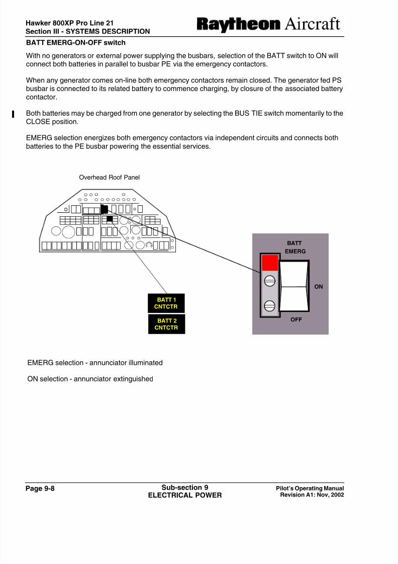
BATT EMERG-ON-OFF switch
With no generators or external power supplying the busbars, selection of the BATT switch to ON willconnect both batteries in parallel to busbar PE via the emergency contactors.
When any generator comes on-line both emergency contactors remain closed. The generator fed PSbusbar is connected to its related battery to commence charging, by closure of the associated battery
contactor.
Both batteries may be charged from one generator by selecting the BUS TIE switch momentarily to theCLOSE position.
EMERG selection energizes both emergency contactors via independent circuits and connects bothbatteries to the PE busbar powering the essential services.
BATT
EMERG
ON
OFF
BATT 1
CNTCTR
BATT 2
CNTCTR
EMERG selection - annunciator illuminated
ON selection - annunciator extinguished
Overhead Roof Panel
7/29/2019 hawker beechcraft
http://slidepdf.com/reader/full/hawker-beechcraft 9/24
Page 9-9Pilot’s Operating Manual
Revision A1: Nov, 2002
Sub-section 9
ELECTRICAL POWER
Hawker 800XP Pro Line 21
Section III - SYSTEMS DESCRIPTION
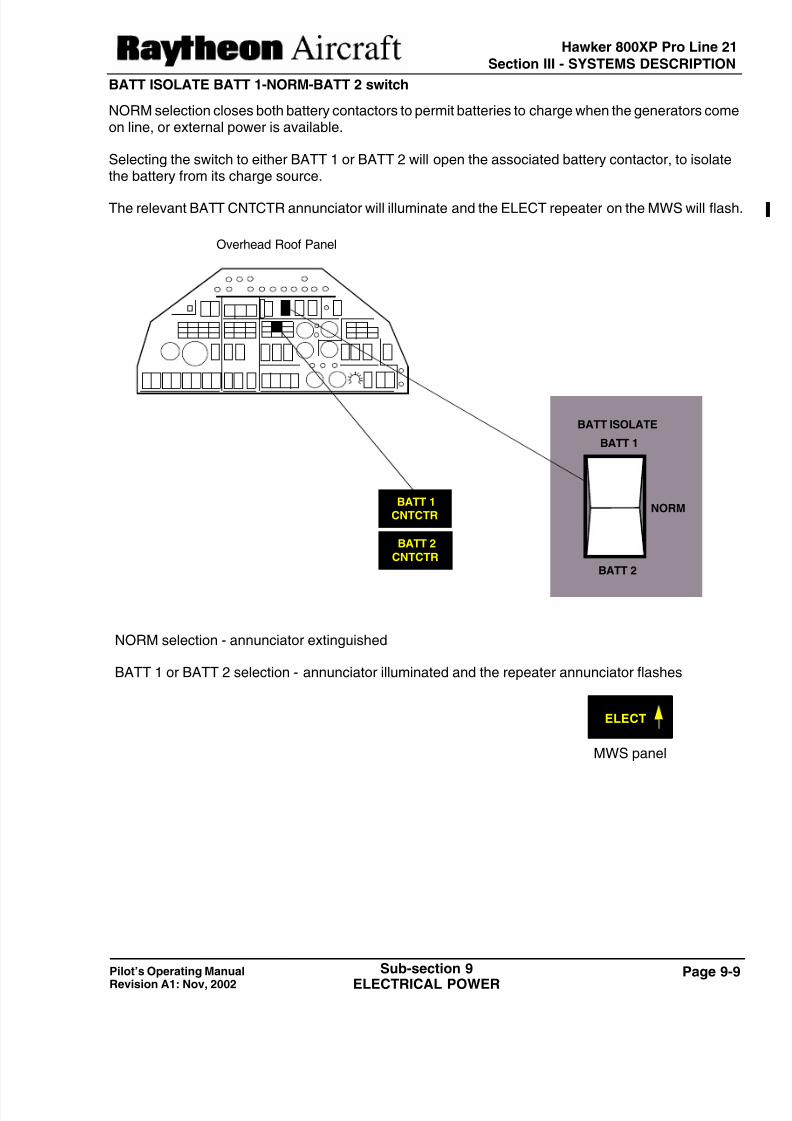
BATT ISOLATE BATT 1-NORM-BATT 2 switch
NORM selection closes both battery contactors to permit batteries to charge when the generators comeon line, or external power is available.
Selecting the switch to either BATT 1 or BATT 2 will open the associated battery contactor, to isolatethe battery from its charge source.
The relevant BATT CNTCTR annunciator will illuminate and the ELECT repeater on the MWS will flash
NORM selection - annunciator extinguished
BATT 1 or BATT 2 selection - annunciator illuminated and the repeater annunciator flashes
BATT 1CNTCTR
BATT 2
CNTCTR
NORM
BATT 2
BATT ISOLATE
BATT 1
MWS panel
ELECT
Overhead Roof Panel

7/29/2019 hawker beechcraft
http://slidepdf.com/reader/full/hawker-beechcraft 10/24
Page 9-10 Pilot’s Operating Manual
Revision A1: Nov, 2002
Sub-section 9
ELECTRICAL POWER
Hawker 800XP Pro Line 21Section III - SYSTEMS DESCRIPTION
+ +-
STARTER BUSBAR
No. 1STARTER
GEN
No. 2
STARTER
GEN
APU
STARTER
GEN
APU START
GEN LINE
CONTACTORNo. 2
GEN LINE
CONTACTORNo. 1
PE BUSBAR
BATT 1 BATT 2
INTERNAL START
CONTACTOR
EMERGENCY CONTACTORS
PE 2
GEN SHUNT
No. 1GEN SHUNT
No. 2
APU GEN
SHUNT
EXTERNAL POWERCONTACTOR
TO PS2(a) AND PS2(b)
BUSBARS
TO PS1(a) AND PS1(b)BUSBARS
PS2 BUSBARPS1 BUSBAR
OPERATING
ENG 1
GEN 1
FAIL
GEN 2
FAIL
BUS TIEOPEN
BATT 2CNTCTR
BATT 1CNTCTR
Figure 3
Battery Switch ON
POWERDIODE
POWERDIODE
POWERDIODE
POWERDIODE
OPERATING
ENG 2
PWR ONPUSH FOR
ABORT
APU GEN
FAIL

7/29/2019 hawker beechcraft
http://slidepdf.com/reader/full/hawker-beechcraft 11/24
Page 9-11Pilot’s Operating Manual
Revision A1: Nov, 2002
Sub-section 9
ELECTRICAL POWER
Hawker 800XP Pro Line 21
Section III - SYSTEMS DESCRIPTION
BUS TIE CLOSE-OPEN switch
Following an abnormal electrical condition, selecting the BUS TIE switch to OPEN splits the busbarsystem into two single-channel busbars.
GEN 1 and GEN 2 CLOSE-TRIP switches
A three position, spring-loaded to center, generator control switch labelled GEN 1 or GEN 2CLOSE/TRIP is connected into each generator circuit. Operated momentarily to the TRIP position, itwill disconnect its associated generator from the busbars and isolate its field circuit and illuminate thefollowing annunciators. Operated to the CLOSE position, and held for 5 seconds, will reset thegenerator field circuit, and subsequent release to the center position will allow the Generator Line
Contactor (GLC) to close, provided that no fault exists, to connect the generator to the busbars.
OPEN selection - annunciator illuminated
CLOSE selection - annunciator extinguished
BUS TIEOPEN
OPEN
BUS TIE
CLOSE
Overhead Roof Panel
GEN 1FAIL
GEN 2
FAILand/or
Overhead Roof Panel
GEN 2
CLOSE
TRIP
GEN 1
CLOSE
TRIP

7/29/2019 hawker beechcraft
http://slidepdf.com/reader/full/hawker-beechcraft 12/24
Page 9-12 Pilot’s Operating Manual
Revision A1: Nov, 2002
Sub-section 9
ELECTRICAL POWER
Hawker 800XP Pro Line 21Section III - SYSTEMS DESCRIPTION
+ +-
STARTER BUSBAR
No. 1STARTER
GEN
No. 2
STARTER
GEN
APU
STARTER
GEN
APU START
GEN LINE
CONTACTORNo. 2
GEN LINE
CONTACTORNo. 1
PE BUSBAR
BATT 1 BATT 2
INTERNAL START
CONTACTOR
EMERGENCY CONTACTORS
PE 2
GEN SHUNT
No. 1GEN SHUNT
No. 2
APU GEN
SHUNT
EXTERNAL POWERCONTACTOR
TO PS2(a) AND PS2(b)
BUSBARS
TO PS1(a) AND PS1(b)BUSBARS
PS2 BUSBARPS1 BUSBAR
OPERATING
ENG 1
Figure 4
Normal Flight Conditions
POWERDIODE
POWERDIODE
POWERDIODE
POWERDIODE
OPERATING
ENG 2
PWR ONPUSH FOR
ABORT
APU GEN
FAIL

7/29/2019 hawker beechcraft
http://slidepdf.com/reader/full/hawker-beechcraft 13/24
Page 9-13Pilot’s Operating Manual
Revision A1: Nov, 2002
Sub-section 9
ELECTRICAL POWER
Hawker 800XP Pro Line 21
Section III - SYSTEMS DESCRIPTION
ENGINE START USING EXTERNAL POWER
Selecting the EXT PWR switch to ON with a suitable external power supply unit will energize all busbarsincluding the start busbar providing that internal start power has not been previously selected.
Operation of the START PWR push switch illuminates the PWR ON/PUSH FOR ABORT annunciatorand brings the start circuit to a state of readiness for ENGINE START switch selection. This push switch
operation also inhibits an internal start.
A warning horn will sound if the switch is operated and the LANDING GEAR selector is not in the downposition.
NOTES:
1. No. 1 avionics and other essential loads should only be used prior to engine starting.
2. No. 2 engine is started first and then its generator is used as detailed below.
At ENGINE START switch operation (ENG 1 or 2) the Generator Control Unit (GCU) initiates the startcycle. Illumination of the OPERATING annunciator indicates completion of the start hold-on circuit,allowing release of the ENGINE START switch.
With the start busbar connected to the starter/generator, the engine motors. When N2 RPM reaches10% or more and N1 is indicating, the HP cock is selected open to supply fuel to the engine and alsoenergizes the igniter unit through the HP cock microswitch.
As the engine reaches self sustaining speed, the GCU initiates a start cut-off sequence. At cut-off, theOPERATING annunciator extinguishes.
ABORT START
The starting sequence may be aborted at any time by a second operation of the START PWR switch.
This initiates a start cut-off sequence by removing the supply to the GCU and extinguishes the PWR
ON PUSH FOR ABORT and OPERATING annunciators.
ENGINE START
STARTPWRENG 1 ENG 2
Overhead Roof Panel
PWR ON
PUSH FOR
ABORT
OPERATING OPERATING

7/29/2019 hawker beechcraft
http://slidepdf.com/reader/full/hawker-beechcraft 14/24
Page 9-14 Pilot’s Operating Manual
Revision A1: Nov, 2002
Sub-section 9
ELECTRICAL POWER
Hawker 800XP Pro Line 21Section III - SYSTEMS DESCRIPTION
+ +-
STARTER BUSBAR
PS2 BUSBARPS1 BUSBAR
No. 1STARTER
GEN
No. 2
STARTER
GEN
APU
STARTER
GEN
APU START
GEN LINECONTACTOR
No. 2
GEN LINECONTACTOR
PE BUSBAR
BATT 1 BATT 2
INTERNAL STARTCONTACTOR
EMERGENCY CONTACTORS PE 2
GEN SHUNTNo. 1
GEN SHUNTNo. 2
APU GENSHUNT
EXTERNAL POWER
CONTACTOR
TO PS2(a) AND PS2(b)
BUSBARS
TO PS1(a) AND PS1(b)
BUSBARS
PWR ON
PUSH FOR
ABORT
BATT 1CNTCTR
BATT 2CNTCTR
GEN 2
FAIL
BUS TIEOPEN
GEN 1
FAIL
OPERATING
ENG 2
OPERATING
ENG 1
Figure 5
Internal Start with No. 2 Engine Selected
POWERDIODE
POWERDIODE
POWERDIODE
POWERDIODE
APU GEN
FAILNo. 1

7/29/2019 hawker beechcraft
http://slidepdf.com/reader/full/hawker-beechcraft 15/24
Page 9-15Pilot’s Operating Manual
Revision A1: Nov, 2002
Sub-section 9
ELECTRICAL POWER
Hawker 800XP Pro Line 21
Section III - SYSTEMS DESCRIPTION
ENGINE START USING BATTERY POWER (Figure 5)
Selecting the BATT switch to ON energizes PE busbar and makes the battery power available at theinternal start contactor. Operation of the START PWR energizes the internal start contactors whichconnect both batteries to the start busbar and brings the system to a state of readiness for ENGINESTART.
When the START PWR switch is operated the integral PWR ON PUSH FOR ABORT annunciatorilluminates and the generator fed busbars and both batteries are connected to the start busbar.
Pushing either ENGINE START switch (ENG 1 or 2) illuminates the OPERATING annunciator andbusbars PS1 and PS2, with the generator, will be disconnected from the start busbar. The engine starteris then energized from the batteries.
WITH A GENERATOR ON LINE
With a main engine or APU generator on-line, and the BUS TIE closed, the generator and both batterieswill be connected to busbars PS1, PS2 and PE.
DC POWER GENERATION
Two 28 VDC starter/generators, one driven from each engine, serve as the primary source of power forthe airplane. The generators are self-exciting and each produce a rated power output of 9 kW when theengine reaches self-sustaining speed. A third starter/generator, driven from the APU (if installed) is alsoavailable. The output voltage of each generator is stabilized by an associated generator control unit(GCU). The GCUs provide load equalization when the generator outputs are paralleled.
For engine starting, the generator operates as a starter motor powered by a 28 VDC ground supply, orby the airplane main batteries connected in parallel. At starter cut-off, the generator control unit (GCU)voltage regulator assumes control of the starter/generator field. Provided the quality of generator output
is satisfactory, an output from the GCU will close the generator line contactor (GLC) connecting thegenerator to its associated busbar (PS1 or PS2). When the GLC closes, the related GEN FAILannunciator extinguishes.
NOTES:
1. Closure of the GLC is inhibited when busbar voltage is higher than generated voltage and when EXT POWER is ON.
2. Should the generator have been previously tripped manually, it will require to be man- ually reset.
ENGINE START
STARTPWRENG 1 ENG 2
OPERATINGOPERATING
Overhead Roof Panel
PWR ON
PUSH FOR
ABORT

7/29/2019 hawker beechcraft
http://slidepdf.com/reader/full/hawker-beechcraft 16/24
Page 9-16 Pilot’s Operating Manual
Revision A1: Nov, 2002
Sub-section 9
ELECTRICAL POWER
Hawker 800XP Pro Line 21Section III - SYSTEMS DESCRIPTION
In the event of reverse current, overvoltage, or over excitation faults being detected, the GCU will signalthe GLC to open, thereby removing the faulty system from the busbars and illuminating the relevantGEN FAIL annunciator.
NOTE: An attempt to reinstate an off-line generator can be made using the GEN CLOSE-TRIP switch.
SINGLE GENERATOR FAILURE (Figure 6)
A faulty generator may be tripped off-line automatically by its GCU, or by operation of the GEN CLOSE-TRIP switch to the momentary TRIP position. With the unserviceable generator off-line, operating theBUS TIE switch to CLOSE closes the BUS TIE contactor so that the serviceable generator feedsbusbars PS1 and PS2 as well as PE.
DOUBLE GENERATOR FAILURE (Figure 7)
Following a double generator failure, both generator contactors open. Both battery contactors also opento prevent the batteries from powering the non-essential loads on PS1 and PS2 busbars.
The following annunciators will illuminate.
Selection of the BATT switch to EMERG connects direct supplies from the batteries to the emergencycontactors to make sure they remain energized closed. These supplies also make sure the batterycontactors are opened, should they have failed to do so due to a fault in the automatic circuits. Toachieve the maximum time on battery power, it is necessary that load-shedding is carried out.
Refer to the Pilot Checklist - EMERGENCY PROCEDURES - for DOUBLE GENERATOR FAILURE.
MWS panel
ELECT
CNTCTR
BATT 1
CNTCTR
BATT 2
FAIL
GEN 1
FAIL
GEN 2BUS TIE
OPEN
Repeater annunciator flashes
XS 1FAIL
XS 2
FAIL
XE
FAIL
INV 1FAIL
INV 2
FAILSTBY INV
ON
Overhead Roof Panel

7/29/2019 hawker beechcraft
http://slidepdf.com/reader/full/hawker-beechcraft 17/24
Page 9-17Pilot’s Operating Manual
Revision A1: Nov, 2002
Sub-section 9
ELECTRICAL POWER
Hawker 800XP Pro Line 21
Section III - SYSTEMS DESCRIPTION
+ +-
STARTER BUSBAR
PS2 BUSBARPS1 BUSBAR
No. 1STARTER
GEN
No. 2
STARTER
GEN
APU
STARTER
GEN
APU START
GEN LINECONTACTOR
No. 2
GEN LINE
CONTACTOR
PE BUSBAR
BATT 1 BATT 2
INTERNAL STARTCONTACTOR
EMERGENCY CONTACTORS PE 2
GEN SHUNTNo. 1
GEN SHUNTNo. 2
APU GENSHUNT
EXTERNAL POWER
CONTACTOR
TO PS2(a) AND PS2(b)
BUSBARS
TO PS1(a) AND PS1(b)
BUSBARS
PWR ON
PUSH FOR
ABORT
GEN 1
FAIL
OPERATING
ENG 2
OPERATING
ENG 1
Figure 6Single Generator Failure
No. 1
POWERDIODE
POWERDIODE
POWERDIODE
POWERDIODE
APU GEN
FAIL
GEN 2
FAIL

7/29/2019 hawker beechcraft
http://slidepdf.com/reader/full/hawker-beechcraft 18/24
Page 9-18 Pilot’s Operating Manual
Revision A1: Nov, 2002
Sub-section 9
ELECTRICAL POWER
Hawker 800XP Pro Line 21Section III - SYSTEMS DESCRIPTION
+ +-
STARTER BUSBAR
PS2 BUSBARPS1 BUSBAR
No. 1STARTER
GEN
No. 2
STARTER
GEN
APU
STARTER
GEN
APU START
GEN LINECONTACTOR
No. 2
GEN LINE
CONTACTOR
PE BUSBAR
BATT 1 BATT 2
INTERNAL STARTCONTACTOR
EMERGENCY CONTACTORS PE 2
GEN SHUNTNo. 1
GEN SHUNTNo. 2
APU GENSHUNT
EXTERNAL POWERCONTACTOR
TO PS2(a) AND PS2(b)
BUSBARS
TO PS1(a) AND PS1(b)
BUSBARS
PWR ON
PUSH FOR
ABORT
OPERATING
ENG 2
OPERATING
ENG 1
Figure 7Double Generator Failure
No. 1
POWERDIODE
POWERDIODE
POWERDIODE
POWERDIODE
APU GEN
FAIL
GEN 2
FAIL
GEN 1
FAIL
BATT 1CNTCTR
BATT 2CNTCTR
BUS TIEOPEN
7/29/2019 hawker beechcraft
http://slidepdf.com/reader/full/hawker-beechcraft 19/24
Page 9-19Pilot’s Operating Manual
Revision A1: Nov, 2002
Sub-section 9
ELECTRICAL POWER
Hawker 800XP Pro Line 21
Section III - SYSTEMS DESCRIPTION
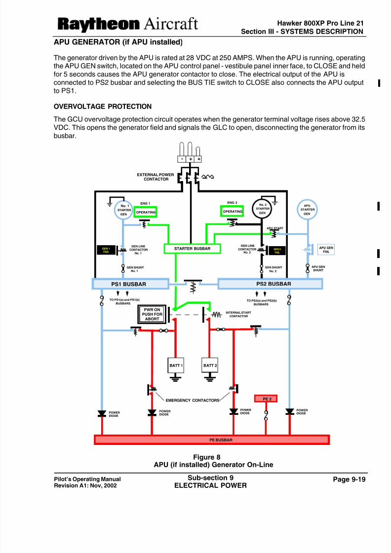
APU GENERATOR (if APU installed)
The generator driven by the APU is rated at 28 VDC at 250 AMPS. When the APU is running, operatingthe APU GEN switch, located on the APU control panel - vestibule panel inner face, to CLOSE and heldfor 5 seconds causes the APU generator contactor to close. The electrical output of the APU isconnected to PS2 busbar and selecting the BUS TIE switch to CLOSE also connects the APU outputto PS1.
OVERVOLTAGE PROTECTION
The GCU overvoltage protection circuit operates when the generator terminal voltage rises above 32.5VDC. This opens the generator field and signals the GLC to open, disconnecting the generator from itsbusbar.
+ +-
STARTER BUSBAR
PS2 BUSBARPS1 BUSBAR
No. 1STARTER
GEN
No. 2
STARTER
GEN
APU
STARTER
GEN
APU START
GEN LINE
CONTACTORNo. 2
GEN LINECONTACTOR
No. 1
PE BUSBAR
BATT 1 BATT 2
INTERNAL START
CONTACTOR
EMERGENCY CONTACTORS PE 2
GEN SHUNTNo. 1
GEN SHUNT
No. 2
APU GENSHUNT
EXTERNAL POWERCONTACTOR
TO PS2(a) and PS2(b)
BUSBARS
TO PS1(a) and PS1(b)
BUSBARS
OPERATING
ENG 2
GEN 2
FAIL
GEN 1FAIL
PWR ONPUSH FOR
ABORT
POWERDIODE
POWERDIODE
POWERDIODE
POWERDIODE
OPERATING
ENG 1
APU GEN
FAIL
Figure 8APU (if installed) Generator On-Line

7/29/2019 hawker beechcraft
http://slidepdf.com/reader/full/hawker-beechcraft 20/24
Page 9-20 Pilot’s Operating Manual
Revision A1: Nov, 2002
Sub-section 9
ELECTRICAL POWER
Hawker 800XP Pro Line 21Section III - SYSTEMS DESCRIPTION
AC POWER
AC power is supplied from two sources:
• DC driven static inverters
• Engine driven alternators
CONTROLS and INDICATIONS
All controls and indicators, with the exception of the ELECT repeater annunciator on the MWS panel,are located on the AC POWER section of the overhead roof panel. The main inverter START-STOPswitches are three position switches, spring-loaded to the center position.
The illumination of the XE FAIL annunciator will also result in the red flashing MWS master warninglamps on the glareshield to operate. The ELECT repeater annunciator will flash when any of thefollowing annunciators illuminate:
The AC VOLTS indicator is calibrated to read from 50 to 150 VAC. Its face has a red segment from 50volts to 100 volts and another red segment from 130 volts to 150 volts.
Voltage on busbars XS 1, XE and XS 2 may be displayed by selection of the associated voltmeter rotaryswitch.
AC POWER
1111
100120
AC
v
60
80
140
XEXS1 XS2
STBY INVARM
INV 1START
INV 2START
STOP OFF STOP
XS 1FAIL
XS 2
FAIL
XE
FAIL
INV 1FAIL
INV 2
FAIL
STBY INV
ON
XFEROFF
B6
B5B4
B3
ELECT
Repeater annunciator flashes
MWS panel
Overhead Roof Panel

7/29/2019 hawker beechcraft
http://slidepdf.com/reader/full/hawker-beechcraft 21/24
Page 9-21Pilot’s Operating Manual
Revision A2: Nov, 2004
Sub-section 9
ELECTRICAL POWER
Hawker 800XP Pro Line 21Section III - SYSTEMS DESCRIPTION
STATIC INVERTERS
Two 1500VA, 115V, 400 Hz. main static inverters, designated No. 1 and No. 2, are installed in the rearequipment bay. Under normal operating conditions, these main inverters provide power to the airplane’sAC busbars. A 250VA, 115V, 400Hz. standby inverter is installed in the rear equipment bay to poweressential AC services in the event of failure of both main inverters.
Starting No. 1 Inverter Momentarily selecting INV 1 switch to the START position causes the following actions:
• Energize No. 1 inverter and connect its output to XS 1 busbar.
• Busbars XE and XS 2 will be supplied from XS 1 via the auto transfer circuit.
• The following annunciators will extinguish: XS 1 FAIL, INV 1 FAIL, XE FAIL and XS 2 FAIL. Thered MWS master warning lamps will also cease to operate.
• Annunciator INV 2 will remain illuminated.
Starting No. 2 inverter
With the No. 1 inverter on-line, momentarily selecting the INV 2 switch to START causes the followingactions:
• Energizes No. 2 inverter.
• Disconnect busbar XS 2 from the output of No. 1 inverter.
• Connect No. 2 inverter output to XS 2 busbar.
• INV 2 FAIL annunciator and the ELECT repeater annunciator to go out.
Failure Of a Main Inverter
Failure of one main inverter results in the related INV FAIL annunciator and ELECT repeater toilluminate. The auto transfer circuit connects the remaining main inverter to all three busbars.
Failure Of Both Main Inverters
Provided the STBY INV switch is selected to ARM, failure of both main inverters results in the followingactions:
• Energizes the standby inverter and connect its output to XE busbar.
• The STBY INV ON annunciator will illuminate.
• The XS 1, INV 1, XS 2 and INV 2 FAIL annunciators will illuminate, together with the ELECTrepeater.
NOTE: If the standby inverter fails while operating, the XE FAIL annunciator will illuminate and theMWS master warning lamps will flash.

7/29/2019 hawker beechcraft
http://slidepdf.com/reader/full/hawker-beechcraft 22/24
Page 9-22 Pilot’s Operating Manual
Revision A2: Nov, 2004
Sub-section 9
ELECTRICAL POWER
Hawker 800XP Pro Line 21Section III - SYSTEMS DESCRIPTION
AC POWER DISTRIBUTION
Two main busbars XS 1 and XS 2 and an essential busbar XE are provided. During normal operation,busbars XS 1 and XE are fed by No. 1 inverter and XS 2 by No. 2 inverter.
In the event of a single main inverter failure, the remaining main inverter output will be automaticallyswitched to supply all three busbars. If failure of both main inverters should occur, essential services
supplied from busbar XE will be maintained by the standby inverter.
XS 1 XS 2
XE
PS 1 PS 2 PE
XS 1FAIL
INV 1FAIL
XS 2
FAIL
INV 2FAIL
STBY INVON
XEFAIL
Figure 8
Inverter System Busbars - Simplified
STOP
INV 1
START
STOP
STBY INV
STOP
INV 2
STARTSTART
STBY INVERTERNo. 1 INVERTER No. 2 INVERTER
AUTO TRANSFER
STALL
VANE
HEAT

7/29/2019 hawker beechcraft
http://slidepdf.com/reader/full/hawker-beechcraft 23/24
Page 9-23Pilot’s Operating Manual
Revision A1: Nov, 2002
Sub-section 9
ELECTRICAL POWER
Hawker 800XP Pro Line 21
Section III - SYSTEMS DESCRIPTION
ALTERNATOR POWER SUPPLY
The AC generated power is supplied from two 208V, frequency wild, three phase alternators, one drivenby each engine. This supply is used to power the windscreen and side screen heating and the vaneheaters.
Each alternator is controlled by an ALTERNATOR 1 or 2 ON/OFF switch located at the top of the ICE
PROTECTION section of the overhead roof panel.
Failure of an alternator is indicated by an ALTR 1 or 2 FAIL annunciator on the overhead roof panel.
OFF
ALTERNATOR
1 ON 2
Overhead Roof Panel

7/29/2019 hawker beechcraft
http://slidepdf.com/reader/full/hawker-beechcraft 24/24
Hawker 800XP Pro Line 21Section III - SYSTEMS DESCRIPTION
Intentionally left blank