hazard identification and safety goals on power...
TRANSCRIPT

Hazard identification and safety goals on power electronics in hybrid vehicles
Master of Science Thesis
FREDRIK WALDERYD
Department of Energy and Environment Division of Electric Power Engineering CHALMERS UNIVERSITY OF TECHNOLOGY Göteborg, Sweden, 2010


Hazard identification and safety goals on power electronics in hybrid vehicles
FREDRIK WALDERYD
Department of Energy and Environment CHALMERS UNIVERSITY OF TECHNOLOGY
Göteborg, Sweden, 2010

Hazard identification and safety goals on power electronics in hybrid vehicles
FREDRIK WALDERYD
© FREDRIK WALDERYD, 2010.
Department of Energy and Environment Chalmers University of Technology SE-412 96 Göteborg Sweden Telephone + 46 (0)31-722 1000
Cover: model of car with eTVD
Chalmers Bibliotek, Reproservice Göteborg, Sweden 2010
Hazard identification and safety goals on power electronics in hybrid vehicles FREDRIK WALDERYD Department of Energy and Environment Chalmers University of Technology
Abstract The task of this master thesis has been to implement part 3 of ISO26262 into Haldex new eTVD, electric torque vectoring drive. It is an electrical rear axis for a passenger car. This is a stage in the more environmental friendly vehicle industry. ISO26262 is a new, soon to be released standard for safety of the using of electrical equipment within the car.
ISO26262 is a new safety standard for E/E-system (electronic/electrical-system) within the car, developed in collaboration with different car manufactures. Many of them will demand the suppliers to implement ISO26262. The purpose is to work for a common standard for the safety.
A first release of the standard will be probably be in the start of year 2011. Today we are in the draft stage and after this the final draft will be assigned. The Swedish name for ISO26262 will probably be SS-ISO26262.
Keyword: ISO26262, eTVD, Concept Phase, Haldex

ii
Sammanfattning Detta är ett examensarbete för Fredrik Walderyd för Chalmers Tekniska Högskola, våren 2010. Examensarbetet är en del av kriterierna som ska uppfyllas för att få en Master of Science-examen inom Electric Power Engineering. Arbetet är utfört i samarbete med Haldex Traction AB i Landskrona.
Uppgiften har varit att tillämpa ISO26262 för Haldex nya eTVD, electric torque vectoring drive. Detta är en elektiskt driven bakaxel för en hybridbil som även ska kunna tillämpa torque vectoring, som innebär att man kan bestämma när man vill lägga på moment på ett specifikt bakhjul. Detta för att kunna få en bil med bättre köregenskaper i kurvor och snäva svängar.
ISO26262 är en nyutvecklad standard för fordonssäkerhet inom elektroniken i bilen, som är framtagen i samarbete mellan en rad olika biltillverkare.

iii
Preface This is the thesis work for Fredrik Walderyd at Chalmers University of Technology, spring 2010. The thesis has been written as a part of the requirements to obtain a Master of Science degree in Electric Power Engineering. The thesis has been written in collaboration with Haldex Traction AB in Landskrona.
Haldex is a global company working with improvements for the vehicle industry. This is improvements for safety, the environmental and for driving characteristics. The company has an annual turnover exceeding 8 billion SEK and employees more than 4000 persons. The company is divided into three groups; Haldex Commercial Vehicle Systems, Haldex Hydraulic Systems and Haldex Traction Systems. The latter has over 200 employees and is a rapid growing division. Their main product is the Haldex coupling for four wheel drive line for passenger cars. It can be found in brands like VW, Volvo, SAAB and Ford. Haldex AB is located in a few different locations around the world; Sweden, Mexico for instance.
iv
Acknowledgement This master thesis has been carried out at the Department of Energy and Environment, Chalmers University of Technology, in cooperation with Haldex Traction AB.
I would like to thank all those who have helped me conducting this master thesis work.
Daniel Norlen, Haldex Traction AB, for providing the project and for support and ideas about the project.
Torbjörn Thirirnger, Chalmers University of Technology, for his support during this master thesis project with precious guidance and many good advices.
Fredrik Walderyd Helsingborg, September 2010
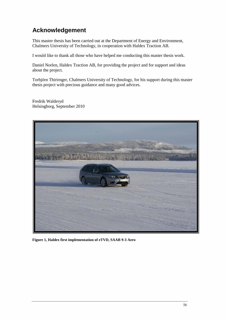
Figure 1, Haldex first implementation of eTVD, SAAB 9-3 Aero

v
List of symbols
Abbreviations ASIL Automotive Safety Integrity Level CPU Central Processing Unit E/E Electronic/Electrical ECU Electronic Control Unit eTVD Electric Torque Vectoring Drive FSC Functional safety concept FSR Functional safety requirements ISO International standard for different applications, for
example quality. It is very broad standardization unit and controls almost everything
PWM Pulse width modulation SOC State of charge of battery TSC Technical safety concept TSR Technical safety requirements
Specific definition of terms used in this work Hybrid A car that can be driven from two kinds of energy
sources. Error Can be a corrupted state, like a wrong value of a
variable Failure When a “subsystem” fails to perform its required
function, like a function returns a wrong value Fault A defect in a system, like a bug in program code Yaw rate Movement of a vehicle around its yaw axis
vi
Figures Figure 1, Haldex first implementation of eTVD, SAAB 9-3 Aero ................................. ivFigure 2, eTVD where the electric motors have been left out for clarification ................ 3Figure 3, model of car with eTVD ................................................................................... 4Figure 4, the stages in concept phase ............................................................................... 8Figure 5, implementation of ISO26262 on new or existing design ................................ 11Figure 6, risk reduction achieved by safety process ....................................................... 12Figure 7, decomposition of safety goal .......................................................................... 20Figure 8, the item called eTVD ...................................................................................... 23Figure 9, intension was a higher longitudinal acceleration than the outcome ................ 24Figure 10, there was an opposite sign of the acceleration achieved compared to the requested ......................................................................................................................... 25Figure 11, there was a correct sign but the amplitude of the acceleration was higher than expected. ......................................................................................................................... 25Figure 12, State machine of the function for the eTVD ................................................. 28Figure 13, Preliminary architecture ................................................................................ 29Figure 14, The ECU/power electronics block ................................................................ 31
Tables Table 1, model of ISO26262 ............................................................................................ 6Table 2, description of the stages in concept phase .......................................................... 9Table 3, definition of a function ..................................................................................... 12Table 4, description of exposure .................................................................................... 14Table 5, examples of exposures ...................................................................................... 15Table 6, description of severity ...................................................................................... 16Table 7, examples of levels of severities ........................................................................ 17Table 8, description of levels of classification ............................................................... 18Table 9, examples of levels of classification .................................................................. 18Table 10, definition of ASIL .......................................................................................... 19Table 11, Table of hazards and ASILs ........................................................................... 26

vii
Table of content 1 Introduction .............................................................................................................. 1
1.1 Problem background .......................................................................................... 11.1.1 ISO26262 .................................................................................................... 11.1.2 eTVD .......................................................................................................... 3
1.2 Purpose of the report .......................................................................................... 51.3 Limitations ......................................................................................................... 5
2 Theory ....................................................................................................................... 62.1 ISO26262 ........................................................................................................... 62.2 Concept Phase of ISO26262 .............................................................................. 8
2.2.1 Item definition .......................................................................................... 102.2.2 Initiation of the Safety Lifecycle .............................................................. 102.2.3 Hazard Analysis and Risk Assessment ..................................................... 112.2.4 Means to attain safety ............................................................................... 132.2.5 Hazard Classification for ASIL ................................................................ 142.2.6 Safety goal ................................................................................................ 19
2.3 D-FMEA .......................................................................................................... 213 Results .................................................................................................................... 23
3.1 Concept Phase .................................................................................................. 233.1.1 Study of eTVD ......................................................................................... 233.1.2 Functions .................................................................................................. 233.1.3 Hazards ..................................................................................................... 253.1.4 Safety goals .............................................................................................. 273.1.5 Functional Safety Concept ....................................................................... 28
4 Conclusion .............................................................................................................. 355 Further work ........................................................................................................... 356 References .............................................................................................................. 367 Appendix ................................................................................................................ 37
7.1 Tree of situations that may lead to a failure ..................................................... 37

1
1 Introduction
1.1 Problem background Since this ISO26262 is a totally new standardization there is a lack of experience. ISO26262 will be compulsory for every manufacturer of devices for the car industry in the near future. It is including rules for how the development shall be progressed and how risk analysis and testing shall be done.
1.1.1 ISO26262 What is ISO26262? The definition of ISO or International Organization for Standardization as it stands for is a non-governmental standardization unit including almost all countries in the world. They have 340 standards for different subjects, where the environmental is one of the biggest. A standard is a definition of how something is made or how something should be handled. It is both for industrial and commercial purpose.
The ISO26262 is a new soon upcoming standard for the vehicle industry [3]. It defines functional safety issues for electronic systems within the car. IEC-61508 is an existing standard for safety, but it originates from the automation and process industries and is not especially made for the car industry, which has its own requirements.
By following ISO26262 risks and hazards should be identified and eliminated in the earliest stage as possible. The standard defines a work for how the work procedure should be done. E.g. the software should be tested in many different stages during the development before the final release.
ISO26262 doesn’t control how powerful the brakes should be, how good the front lights should beam or how loud the horn should sound. Instead the ISO26262 standardize how the safety of the control system for the electrical equipment should be developed. It controls how the brake control system should be developed in order to avoid a failure from happen. A failure caused by that the control software for the brakes causes a total breakdown of the brake system; a failure that no one wants to be happen.
The purpose of following this standard is that the vehicle manufactures, and finally the end customers, may know that the development is done in a specific way, which focuses on functional safety e.g. by following rules etc. Other purposes are to save money in the work process by using standards for the work, increase quality, increase flexibility and reduce of the development time.
2
ISO26262 are using items within the car. The items are defined as electronic safety critical functions within the system (vehicle). The size of the item is determined by common sense of what is practical to handle. The boundaries between the items should have as less interference to other items as possible.
If changes to a system or function, like a new improvement to the adaptive cruise control for instance, have been done since last time an item definition is done, a new item description has to be done in order to find all new safety critical functions. The guideline of how big changes that can be accepted without doing a new analysis are based on:
• Changes in design, function or performance
• Changes of parameters
• Changes to the environment to the item

3
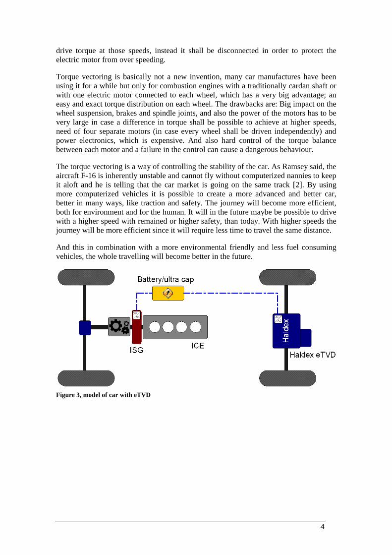
1.1.2 eTVD Haldex has developed, in collaboration with Saab, Volvo, Energimyndigheten and a few more companies and universities, an electric rear axle including torque vectoring, called eTVD, electric Torque Vectoring Drive. The principle is an old invention but the way it’s done and how it is working is totally new. It is called torque vectoring, and it means that it is possible to control on which rear wheel you want to apply the torque on, from the electric motor placed on the axle, figure 3. This makes it possible to create a car with better driving characteristics. It is then possible to do a more narrow turn or to get a car that is more stabile since it is possible to control the torque distribution on the rear wheels independent from each other.
The idea is to build a hybrid car with both an ICE (internal combustion engine) and an eTVD-system.
The eTVD-system consists of an electric motor (hereafter called traction or propulsion motor) that provides propulsion torque to the rear wheels through a planetary gear arrangement on each side, and then a smaller electric motor (hereafter called torque vectoring motor) that can adjust the differential speed left to right between the rear wheels.
The stator of the traction motor is connected to the sun gear of a planetary gear set on each side (see Figure 2, where the electric motors have been left out for clarification). The propulsion torque from the traction motor is then transferred to the rear wheels through the planetary gears. The ring gears are connected by a balance shaft (just with an extra gear on one side that will change rotational direction), and this mechanism will provide the differential functionality that is needed i.e. when driving through a curve.
Connected to the balance shaft (through a gear arrangement that will provide gear reduction) is a smaller electric motor, and this one could be used to speed up the ring gear on one side while slowing down the one on the other side, i.e. a torque vectoring system. Which one of the ring gears that increases in speed depends on the direction of the torque vectoring motor. During straight ahead driving the balance shaft is standing still, while if one side is speeding up (due to driving in a curve or actively applying TV-torque) the balance shaft will start to rotate.
There is also a clutch for disconnecting the traction motor from the wheels, and this is used for vehicle speeds above 130km/h or when a failure occurs. For higher speeds (above 130km/h) the eTVD cannot be used since the electric motor cannot provide any
Figure 2, eTVD where the electric motors have been left out for clarification
4
drive torque at those speeds, instead it shall be disconnected in order to protect the electric motor from over speeding.
Torque vectoring is basically not a new invention, many car manufactures have been using it for a while but only for combustion engines with a traditionally cardan shaft or with one electric motor connected to each wheel, which has a very big advantage; an easy and exact torque distribution on each wheel. The drawbacks are: Big impact on the wheel suspension, brakes and spindle joints, and also the power of the motors has to be very large in case a difference in torque shall be possible to achieve at higher speeds, need of four separate motors (in case every wheel shall be driven independently) and power electronics, which is expensive. And also hard control of the torque balance between each motor and a failure in the control can cause a dangerous behaviour.
The torque vectoring is a way of controlling the stability of the car. As Ramsey said, the aircraft F-16 is inherently unstable and cannot fly without computerized nannies to keep it aloft and he is telling that the car market is going on the same track [2]. By using more computerized vehicles it is possible to create a more advanced and better car, better in many ways, like traction and safety. The journey will become more efficient, both for environment and for the human. It will in the future maybe be possible to drive with a higher speed with remained or higher safety, than today. With higher speeds the journey will be more efficient since it will require less time to travel the same distance.
And this in combination with a more environmental friendly and less fuel consuming vehicles, the whole travelling will become better in the future.
Figure 3, model of car with eTVD

5
1.2 Purpose of the report The task is to do a first implementation of part 3 of ISO26262. This will be done on Haldex project called eTVD. First find all the risks and hazards and then next objective is to classify them out from the severity influence, exposure and controllability of the problem that can be caused by a failure in this specific item. Then try to avoid this failure from occurring.
1.3 Limitations This thesis work has been limited to the concept phase of the ISO26262 implementation, this because a totally implementation is a very big task and should involve people at different position within a company (e.g. for functional safety management). This master thesis work will last for 20 weeks and by doing a rough estimation a complete implementation of ISO26262 will need more time than that. The concept phase is an important part of the implementation of ISO26262. It is in this part that the whole hazards analysis and risk management are placed. Concept phase is also including the initial work to prevent the failures from happen.
6
2 Theory
2.1 ISO26262 The ISO26262 is a new soon upcoming standard for the vehicle industry. It defines functional safety-related issues within the car [1]. By following ISO26262 risks and hazards should be found and eliminated in the earliest stage as possible. The standard defines a work method for how the work procedure should be done.
The purpose of following this standard is that the manufactures and the customers may know that the development is done in a specific way, following rules etc. Other purposes are to save money in the work process by using standards for the work, increase quality, increase flexibility and reduce of the development time.
The items as it is called are defined as functions within the system.
An implementation of ISO26262 would be done as early as possible in the development process, because an early change is much easier to make than a change in the process when the products are delivered.
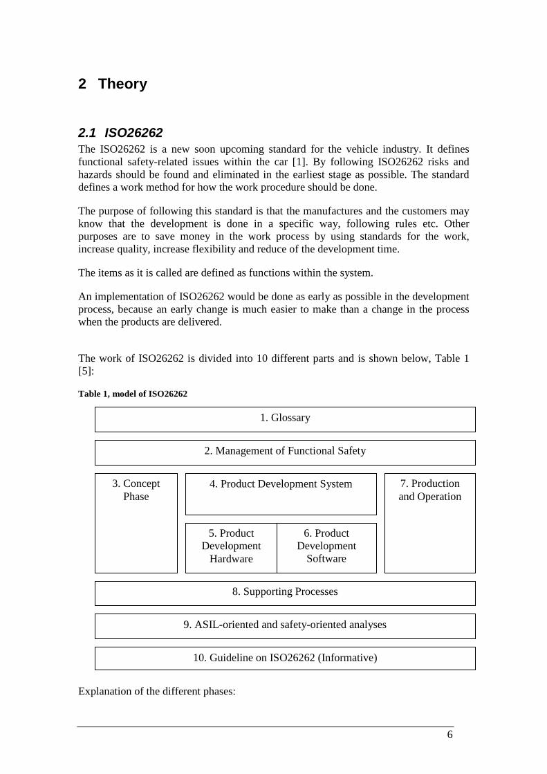
The work of ISO26262 is divided into 10 different parts and is shown below, Table 1 [5]:
Table 1, model of ISO26262
Explanation of the different phases:
1. Glossary
2. Management of Functional Safety
3. Concept Phase
6. Product Development
Software
8. Supporting Processes
5. Product Development
Hardware
4. Product Development System 7. Production and Operation
9. ASIL-oriented and safety-oriented analyses
10. Guideline on ISO26262 (Informative)

7
1. Glossary – Here all the words and phrases are explained for ISO26262.
2. Management of Functional Safety – Management during complete safety lifecycle, safety management during development and safety management activities after release.
3. Concept Phase – Item definition, initiation of the safety lifecycle, hazard analysis and risk assessment and functional safety concept.
4. Product Development System - Specification of technical safety requirements with respect to preliminary architecture assumptions, technical safety requirement specification and specification of system design and technical safety concept.
5. Product Development Hardware – Hardware analysis, design and integration.
6. Product Development Software – Software development, safety specification and testing.
7. Production and Operation – Production, operation, service and decommissioning.
8. Supporting Processes – Overall safety management, configuration, verification, documentation. Someone shall during the process control and document the safety development.
9. ASIL-oriented and safety-oriented analyses – Update of architectural information and ASILs. Safety analyses at applied level.
10. Guideline on ISO26262 – Guideline of the implementation.

8
Item definition Initiation of the safety lifecycle
Hazard analysis and risk assessment
Functional safety concept Figure 4, the stages in concept phase
2.2 Concept Phase of ISO26262
The figure shows the different stages in the concept phase, Figure 4. A more detailed description can be seen in Table 2 [3]

9
Table 2, description of the stages in concept phase
Clause Title Objectives Prerequisites Work products
5 Item definition
The first objective of the item definition is to define and describe the
item The second objective is to support an adequate understanding of the
item so that each activity defined in the safety lifecycle can be
performed.
None Item definition
6 Initiation of the safety lifecycle
The objective of the initiation of the safety
lifecycle is to make the distinction between a new development and
a modification to a previously existing
item. In the case of a
modification the second objective is to
define the safety lifecycle activities that
will be carried out.
Item definition Impact analysis
7 Hazard analysis and risk assessment
The objective of the hazard analysis and risk assessment is to
identify and categorise the hazards of the item
and formulate the safety goals related to
the prevention or mitigation of these hazards, in order to avoid unreasonable
risk.
Item definition
Hazard analysis and risk assessment
Safety goals Verification review of
hazard analysis and risk assessment and
safety goals
8 Functional safety concept
The objective of the functional safety
concept is to derive the functional safety
requirements, from the safety goals, and to allocate them to the
preliminary architectural elements
of the item or to external risk reduction measures in order to ensure the required functional safety.
Item definition Hazard analysis and
risk assessment Safety goals
Functional safety concept
Review of functional safety requirements
10
2.2.1 Item definition An item can either be an E/E-system or a function within the car. The items should be considered from the nature of the car. A normal passenger car is maybe not intended to go off-road, so the function may not be climb a hill with a big slope. That is why a detailed plan of the use of the car has to be considered. E.g. an item within the car is the brake system and then the function may be the ABS-system (anti-lock braking system). Other elements that have to be considered are:
• Purpose and content of the item
• Functional requirements of the item
• Non-functional requirements
• Already known-safety related requirements
• Item boundary and interfaces
• Assumptions shall be verified if used. It is very important that the interfaces to other items are as small as possible, in order to make the implementation of ISO26262 as easy as possible. An interference will result in a more complex way of improving the safety for each item. Two examples of items can be Lane keeping aid or Electronic parking brake.
A fail in an item shall be categorized;
• Fail safe system – A fail is categorized as a minor problem; doesn’t really affect the safety or driving abilities of the car.
• Fail controlled system – A fail makes the car to go into a failsafe state. Maybe the maximum allowed speed of the car is reduced.
• Fault tolerant system – A system where a failure should cause a big safety risk, which means that it has to work all the time, like the steering.
2.2.2 Initiation of the Safety Lifecycle
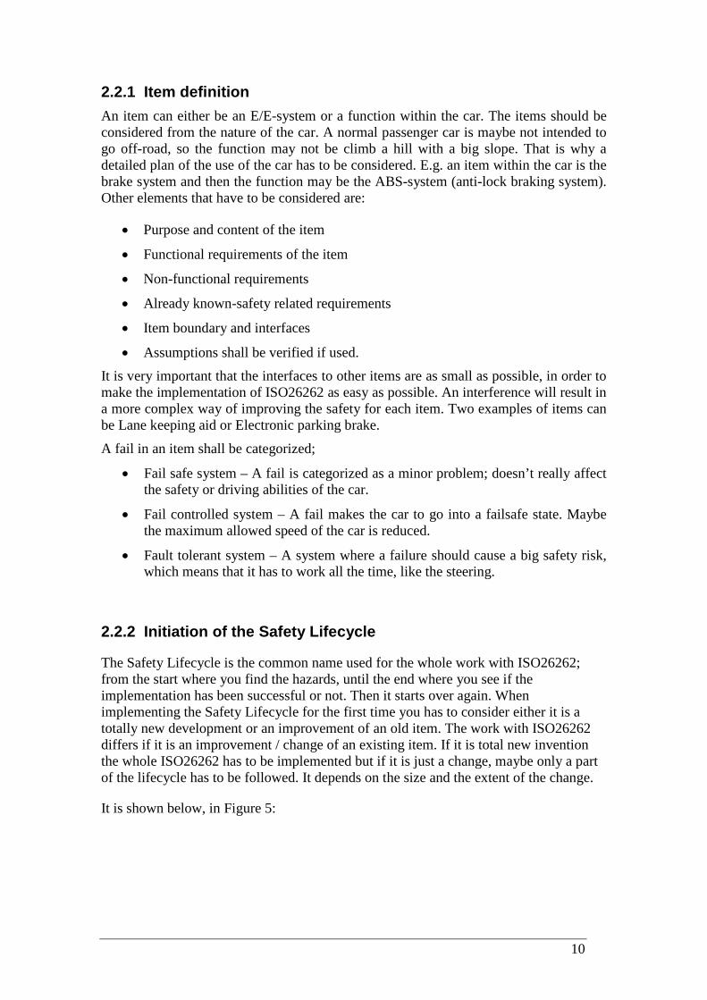
The Safety Lifecycle is the common name used for the whole work with ISO26262; from the start where you find the hazards, until the end where you see if the implementation has been successful or not. Then it starts over again. When implementing the Safety Lifecycle for the first time you has to consider either it is a totally new development or an improvement of an old item. The work with ISO26262 differs if it is an improvement / change of an existing item. If it is total new invention the whole ISO26262 has to be implemented but if it is just a change, maybe only a part of the lifecycle has to be followed. It depends on the size and the extent of the change.
It is shown below, in Figure 5:
11
Figure 5, implementation of ISO26262 on new or existing design
2.2.3 Hazard Analysis and Risk Assessment
When knowing the different items, all the hazards have to be found within each item. Each function shall be done one by one. Hazard is something that may go wrong and then cause an accident.
Example:
Hazard: When driving faster than 200km/h the level on the stereo should not be higher than 80dB.
The classification of the different hazards found is done by ASIL – Automotive Safety Integrity Level. The lowest grade is ASIL A and the highest is ASIL D. For a function with an ASIL lower than an A, it shall be marked with QM, which marks it as a not safety critical function.
For every found hazard an ASIL should be chosen and then at least one safety goal should be stated for every hazard/ASIL.
Safety goal: It shall not be possible to have a higher volume on the stereo than 80dB when driving faster than 200km/h.
No
No
No
New development?
Modification?
Proven in use?
All ISO 26262 activities applied
Impact analysis and activity tailoring
Proven in use argumentation
Yes
Yes
Yes
12
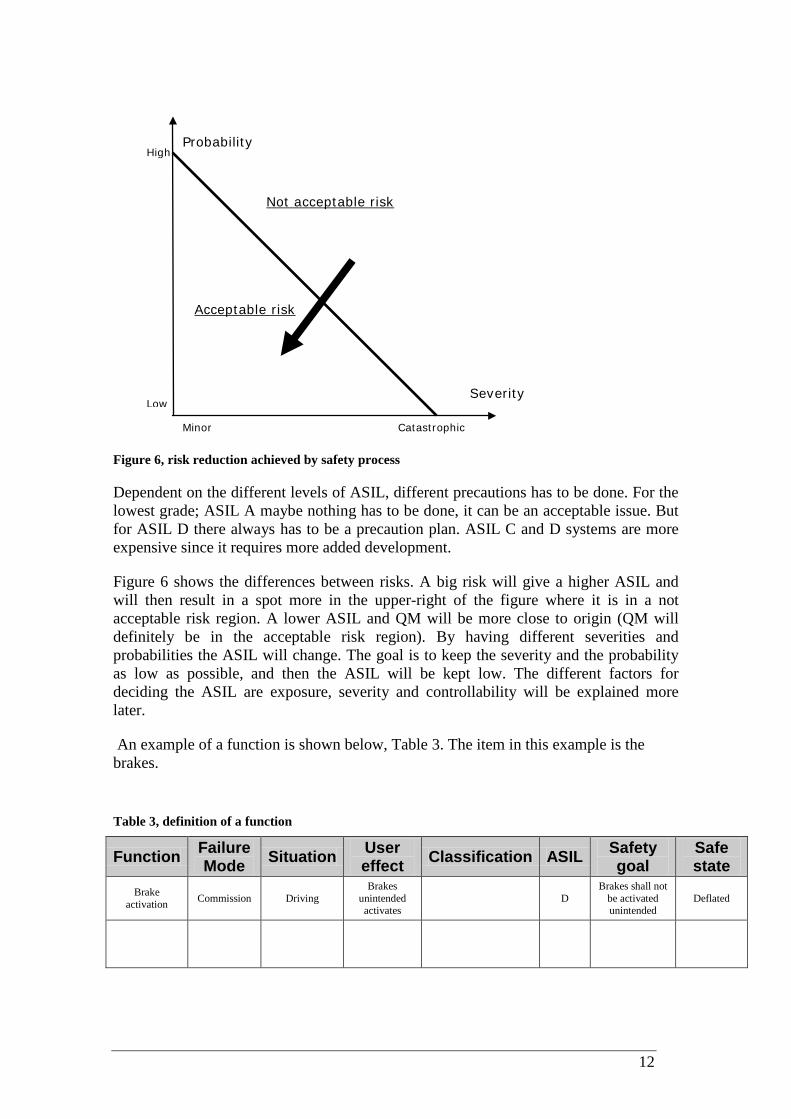
Figure 6, risk reduction achieved by safety process
Dependent on the different levels of ASIL, different precautions has to be done. For the lowest grade; ASIL A maybe nothing has to be done, it can be an acceptable issue. But for ASIL D there always has to be a precaution plan. ASIL C and D systems are more expensive since it requires more added development.
Figure 6 shows the differences between risks. A big risk will give a higher ASIL and will then result in a spot more in the upper-right of the figure where it is in a not acceptable risk region. A lower ASIL and QM will be more close to origin (QM will definitely be in the acceptable risk region). By having different severities and probabilities the ASIL will change. The goal is to keep the severity and the probability as low as possible, and then the ASIL will be kept low. The different factors for deciding the ASIL are exposure, severity and controllability will be explained more later.
An example of a function is shown below, Table 3. The item in this example is the brakes.
Table 3, definition of a function
Function Failure Mode Situation User
effect Classification ASIL Safety goal
Safe state
Brake activation Commission Driving
Brakes unintended activates
D Brakes shall not
be activated unintended
Deflated
High
Probability
Severity
Catastrophic Minor
Low
Not acceptable risk
Acceptable risk

13
Function – the name of the function that may be the problem.
Failure mode – what is the chance of getting a failure in this function? Good words for explaining can be omission and commission.
- Omission – A sudden lack of effect
- Commission – A sudden full effect
Other good words for explaining can be stuck, less, more, early and later.
Situation – when will this happen?
User effect – what happens for the user/driver?
Classification – exposure, severity and controllability.
ASIL – what is the level of this problem?
Safety goal – what is the goal for this, how shall it be prevented from happen?
Safe state – is it possible deflate this problem or will the risk always be there?
2.2.4 Means to attain safety
There are several different ways to obtain a safe product (safe state), e.g. get rid of faults.
• Fault Prevention – Prevent the occurrence or introduction of faults. • Fault Tolerance – Avoid service failures in the presence of faults. • Fault Removal – Remove the faults by testing. • Fault Forecasting – Estimate the fault and consequences of faults.
14
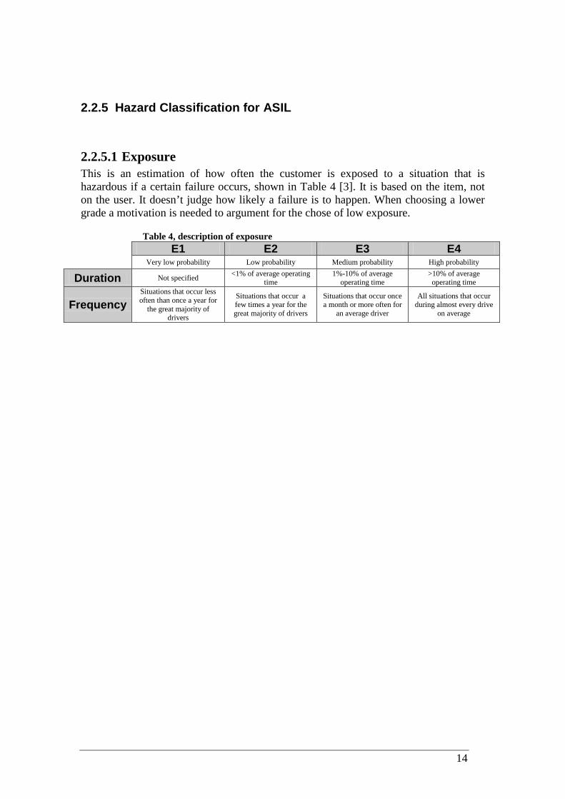
2.2.5 Hazard Classification for ASIL
2.2.5.1 Exposure This is an estimation of how often the customer is exposed to a situation that is hazardous if a certain failure occurs, shown in Table 4 [3]. It is based on the item, not on the user. It doesn’t judge how likely a failure is to happen. When choosing a lower grade a motivation is needed to argument for the chose of low exposure.
Table 4, description of exposure E1 E2 E3 E4 Very low probability Low probability Medium probability High probability
Duration Not specified <1% of average operating time
1%-10% of average operating time
>10% of average operating time
Frequency Situations that occur less often than once a year for
the great majority of drivers
Situations that occur a few times a year for the great majority of drivers
Situations that occur once a month or more often for
an average driver
All situations that occur during almost every drive
on average
15
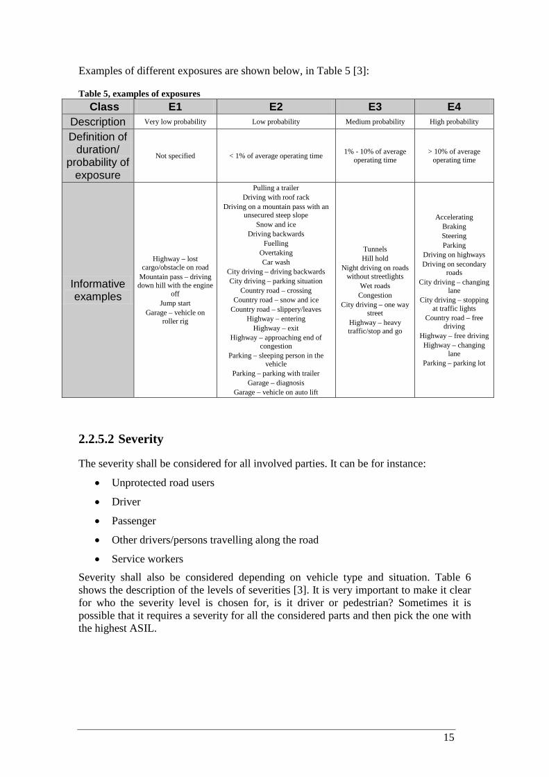
Examples of different exposures are shown below, in Table 5 [3]:
Table 5, examples of exposures Class E1 E2 E3 E4
Description Very low probability Low probability Medium probability High probability
Definition of duration/
probability of exposure
Not specified < 1% of average operating time 1% - 10% of average operating time
> 10% of average operating time
Informative examples
Highway – lost cargo/obstacle on road
Mountain pass – driving down hill with the engine
off Jump start
Garage – vehicle on roller rig
Pulling a trailer Driving with roof rack
Driving on a mountain pass with an unsecured steep slope
Snow and ice Driving backwards
Fuelling Overtaking Car wash
City driving – driving backwards City driving – parking situation
Country road – crossing Country road – snow and ice
Country road – slippery/leaves Highway – entering
Highway – exit Highway – approaching end of
congestion Parking – sleeping person in the
vehicle Parking – parking with trailer
Garage – diagnosis Garage – vehicle on auto lift
Tunnels Hill hold
Night driving on roads without streetlights
Wet roads Congestion
City driving – one way street
Highway – heavy traffic/stop and go
Accelerating Braking Steering Parking
Driving on highways Driving on secondary
roads City driving – changing
lane City driving – stopping
at traffic lights Country road – free
driving Highway – free driving
Highway – changing lane
Parking – parking lot
2.2.5.2 Severity
The severity shall be considered for all involved parties. It can be for instance:
• Unprotected road users
• Driver
• Passenger
• Other drivers/persons travelling along the road
• Service workers
Severity shall also be considered depending on vehicle type and situation. Table 6 shows the description of the levels of severities [3]. It is very important to make it clear for who the severity level is chosen for, is it driver or pedestrian? Sometimes it is possible that it requires a severity for all the considered parts and then pick the one with the highest ASIL.

16
Table 6, description of severity
Class S0 S1 S2 S3
Description No injuries Light and moderate injuries
Severe injuries, possibly life
threatening, survival probable
Life-threatening injuries (survival uncertain) or fatal
injuries
Reference for single injuries
(AIS scale)
Damage that cannot be classified safety-related, e.g.
bumps with roadside infrastructure.
AIS 0
More than 10% probability of AIS 1-6
More than 10% probability of AIS 3-6
More than 10% probability of AIS 5-6
AIS – Abbreviated Injury Scale 1. Minor 2. Moderate 3. Serious 4. Severe 5. Critical 6. Maximum
17
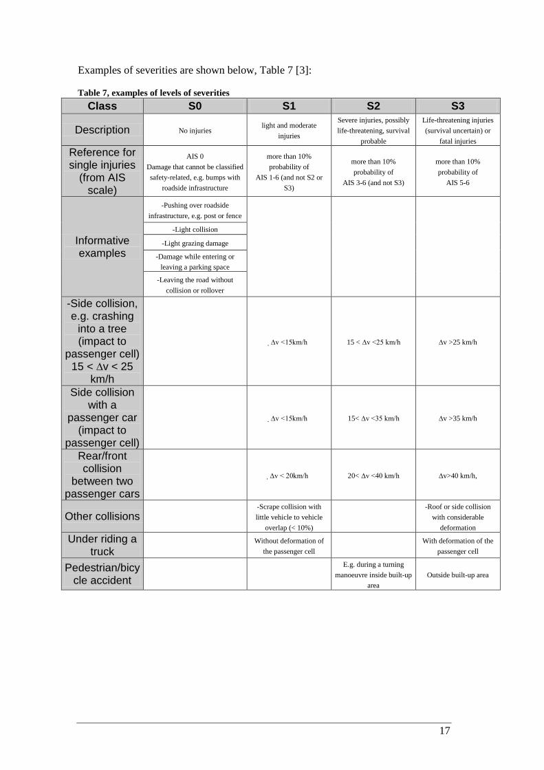
Examples of severities are shown below, Table 7 [3]:
Table 7, examples of levels of severities Class S0 S1 S2 S3
Description No injuries light and moderate
injuries
Severe injuries, possibly life-threatening, survival
probable
Life-threatening injuries (survival uncertain) or
fatal injuries
Reference for single injuries
(from AIS scale)
AIS 0 Damage that cannot be classified safety-related, e.g. bumps with
roadside infrastructure
more than 10% probability of
AIS 1-6 (and not S2 or S3)
more than 10% probability of
AIS 3-6 (and not S3)
more than 10% probability of
AIS 5-6
Informative examples
-Pushing over roadside infrastructure, e.g. post or fence
-Light collision
-Light grazing damage
-Damage while entering or leaving a parking space
-Leaving the road without collision or rollover
-Side collision, e.g. crashing
into a tree (impact to
passenger cell) 15 < ∆v < 25
km/h
∆v <15km/h 15 < ∆v <25 km/h ∆v >25 km/h
Side collision with a
passenger car (impact to
passenger cell)
∆v <15km/h 15< ∆v <35 km/h ∆v >35 km/h
Rear/front collision
between two passenger cars
∆v < 20km/h 20< ∆v <40 km/h ∆v>40 km/h,
Other collisions -Scrape collision with little vehicle to vehicle
overlap (< 10%)
-Roof or side collision with considerable
deformation
Under riding a truck
Without deformation of the passenger cell
With deformation of the
passenger cell
Pedestrian/bicycle accident
E.g. during a turning manoeuvre inside built-up
area Outside built-up area

18
2.2.5.3 Controllability
Controllability is the ability that the driver has to avoid an accident or any other harm. This includes e.g. reaction time, i.e. prevention action for an accident. The levels are defined in Table 8 [3].
Table 8, description of levels of classification Class C0 C1 C2 C3
Description Controllable in general Simply controllable Normally controllable Difficult to control or uncontrollable
Definition Controllable in general
99% or more of all drivers or other traffic participants are usually able to avoid a specific
harm
90% or more of all drivers or other traffic participants are usually able to avoid a specific
harm
Less than 90% of all drivers or other traffic participants are usually able, or barely able, to avoid a specific harm
Examples of controllability’s are shown below, Table 9 [3]:
Table 9, examples of levels of classification Class C0 C1 C2 C3
Description Controllable in general Simply controllable Normally controllable Difficult to control or uncontrollable
Definition Controllable in general
99% or more of all drivers or other traffic participants are
usually able to avoid a specific harm.
90% or more of all drivers or other traffic participants are
usually able to avoid a specific harm.
Less than 90% of all drivers or other traffic participants are usually able, or barely able, to avoid a specific
harm.
Informative examples
Unexpected increase in radio volume
Situations that are considered distracting
Unavailability of a driver assisting system
When starting the vehicle with a locked steering column, the car can be
brought to stop by almost all drivers early enough to avoid
a specific harm to persons nearby.
Faulty adjustment of seats while driving can be
controlled by almost all drivers by bringing the
vehicle to a stop.
Driver can normally avoid departing from the lane in case
of a failure of ABS during emergency braking.
Driver is normally able to avoid departing from the lane in case of a motor failure at high lateral acceleration (motorway exit).
Driver is normally able to bring the vehicle to a stop in case of a total lighting failure at medium or high speed on an unlighted
country road without departing from the lane in an uncontrolled
manner. Driver is normally able to avoid
hitting an unlit vehicle on an unlit country road.
Wrong steering with high angular speed at medium or
high vehicle speed can hardly be controlled by the
driver. Driver normally cannot
avoid departing from the lane on snow or ice on a
bend in case of a failure of ABS during emergency
braking. Driver normally cannot
bring the vehicle to a stop if a total loss of braking performance occurs.
In the case of faulty airbag release at high or moderate
vehicle speed, the driver usually cannot prevent
vehicle from departing from the lane.

19
2.2.5.4 ASIL
When knowing all these three factors it is now possible to arrange an Automotive Safety Integrity Level classification table to get the ASIL code for every hazard.
Table 10, definition of ASIL CO C1 C2 C3 - E0 QM QM QM QM
S0 - QM QM QM QM
S1
E1 QM QM QM QM E2 QM QM QM QM E3 QM QM QM A E4 QM QM A B
S2
E1 QM QM QM QM E2 QM QM QM A E3 QM QM A B E4 QM A B C
S3
E1 QM QM QM A E2 QM QM A B E3 QM A B C E4 QM B C D
By knowing the level of Exposure (E), Classification (C) and Severity (S), the ASIL can be found by looking in the Table 10 [3].
A hazard with E3, S1 and C2 gives an ASIL A.
2.2.6 Safety goal
As mentioned before, every ASIL should have at least one safety goal, and for the higher levels, C and D, it may be good to have even more than one. It may be good to have safety goals even for QM-level. This goal will then become a normal functional requirement and there is no need to have a special safety precaution. It is then very important to create a good motivation for the safety goal.
A safety goal shall be easy to follow and understand without being too complex or being too detailed. The safety goals may include fault detection, driver warnings, back-up mechanisms and functional redundancies. The safety goal shall be stated as a ‘this shall not happen’.
2.2.6.1 Functional safety concept
This is about how a failure shall be detected and avoided. How much tolerance is okay before it turns into a failure? Also warnings for the driver shall be stated in this section. Maybe a lamp will turn on, on the dash board in order to inform the driver of the failure, and then maybe the driver can avoid the failure for turning into an accident.
ASIL D – Highest ASIL C ASIL B ASIL A – Lowest QM – Normal quality management. No safety requirements.

20
The functional safety concept allocates the logical component (i.e. the origin of the signal controlling the function) of the safety. It says that this logical component controls the outcome, which is stated in the safety goal.
First a logical component level architecture shall be derived, of the item and then the task is to see what can be improved in order to improve the safety.
At least one functional safety requirement shall be stated for each safety goal. The FSR shall be stated out from the architecture, where you see all the inputs and outputs to the function. If one input signal is incorrect, what can this cause?
For example a door in the car shall only be able to be opened for speeds under 15km/h, and then it is very good to find two separate ways to avoid any unwanted openings. A second architecture might then be derived.
Here a new switch could be implemented in order to avoid an unwanted opening. Now there are two separately criteria’s that has to be fulfilled before the door can be opened. This is called decomposition, Figure 7, because of that; the ASIL of the first criteria can now be lowered, now since there are two criteria’s.
Figure 7, decomposition of safety goal
The rest of the decompositions are:
ASIL D → ASIL C(D) + ASIL A(D)
ASIL D → ASIL B(D) + ASIL B(D)
ASIL D → ASIL D(D) + QM(D)
ASIL C → ASIL B(C) + ASIL A(C)
ASIL C → ASIL C(C) + QM(C)
ASIL B → ASIL A(B) + ASIL A(B)
ASIL B → ASIL B(B) + QM(B)
ASIL A → ASIL A + QM(A)
Safety goal ASIL D
ASIL B (D) ASIL B (D) Independence
between the two other ones
ASIL D
21
2.3 D-FMEA Hazard analysis is specified in ISO26262 and FMEA is another way to search for failures within product and a process. It is based on the quality improvement method Six Sigma. FMEA stands for Failure Modes and Effect Analysis and is a procedure for analysis of potential failures and classification of a failure to occur [6]. Effect Analysis is a study of the consequences from a failure. It means that for each component in a product a FMEA shall be done.
What happens if there will be a fault in a transistor? What can go wrong with it? FMEA is based on two different types: P-FMEA, where P stands for process and it looks more into what risks there are in a process. The other FMEA is D-FMEA and the D is for design [4]. This is when you design or construct a new product/function. D-FMEA is the closest related to IS026262.
The differences between hazard analysis and D-FMEA are: Hazard analysis (ISO):
• Performed earlier
• Purpose is to find hazards
• Addresses output interfaces, not internals
• Outputs are high level safety requirements
D-FMEA:
• Purpose is to improve quality by verification of design
• D-FMEA assesses internals of a system and is excellent as a verification method.
The difference in work procedure is that for ISO26262, a hazard analysis should be done without concerning any specific component. Only the functions for the product shall be concerned. When knowing all the hazards and then gave them an ASIL, a more detailed level shall be carried out in order to find those elements that may cause this hazard. For FMEA it is the other way around, here the thing is to is look at all the elements to see if a error in it should cause a great failure or not.
The FMEA has a clear procedure:
1. Clear definition – Who is the customer? How shall the work be followed up?
2. Error possibility – What error/errors may occur?
3. Failure effect – What will the consequences be of the errors?
4. Cause of error – What caused the errors?
5. Probability of error - What is the probability of a specific error to occur?
6. Severity of the error - How bad is this error?
7. How big is the probability that the error will be found?

22
When knowing those factors (5-7), a value can be calculated and from the errors with the highest value shall be prioritized. This value is called RPN; from risk priority number.

23
3 Results
3.1 Concept Phase
3.1.1 Study of eTVD
Together with a group of people from Haldex division working with the eTVD a first analysis of possible ways that a hazard can occur for the eTVD is done. Since Haldex only are working with one specific part of the car, and that is the eTVD, which is more exact the rear axle, the only thing that has to be concerned are a longitudinal and lateral acceleration, positive and negative. And also the hazards according to the equipment installed in the car that has to do with the eTVD.
Since Haldex not have done any ISO26262 implementation for their eTVD-device before, a full implementation has to be done, according to the life cycle, however this work is focused on part 3 (Concept Phase) as mentioned earlier.
The item under study here is defined to be the eTVD, its power electronics and cooling system, Figure 8.
The item, is a ‘fail controlled system’, meaning that a failure in the eTVD-device should put the car into a failsafe mode, meaning that it can be driven, possibly with reduced performance, to the nearest workshop or service station.
3.1.2 Functions
There are two main functions for the eTVD, first is to propel the vehicle. Either accelerates in positive or negative direction. It shall also be able to regenerate energy when braking (which is a big advantage of hybrid electrical vehicles). The second is the torque vectoring functionality, with the function of reducing the yaw rate in order to increase the stability during e.g. an avoidance manoeuvre, or to increase lateral acceleration in certain situations in order to improve the turn-in performance. The power electronics is a part of the item and is needed to apply correct current to the motor in every situation in order to achieve desired torque level at each rear tire. The
Item
eTVD Power electronics
Cooling system
Figure 8, the item called eTVD

24
cooling system is for cooling the power electronics and motor, and consists of both fans and pumps for liquids, and is the last part of the item.
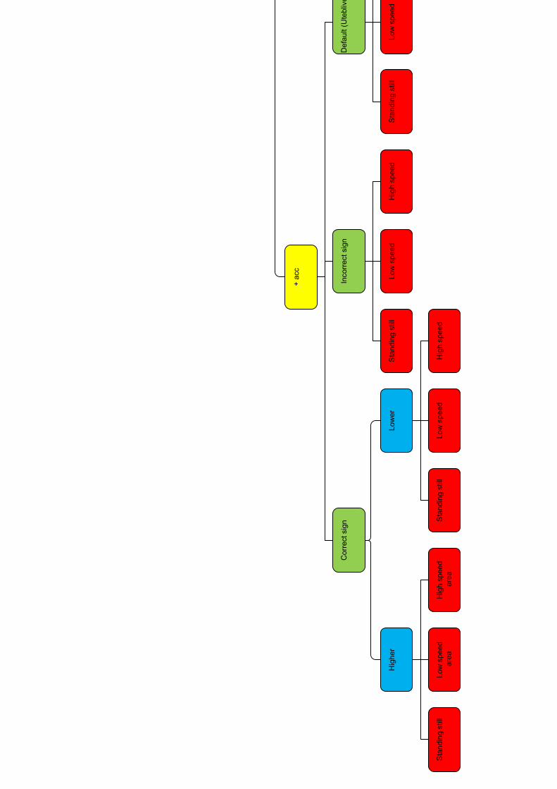
A function tree has been developed where it is possible to follow different possible hazardous situations that may occur. The function tree can be seen in the appendix. It has been found that the vehicle might be in three different situations;
• A (almost) standing still area – This can be parking lots, garages, crosswalks or red light. This classification is because they are all zones where the car is almost standing still or totally standing still. People, and possible even children, are walking around and between the cars.
• Low speed area – This is areas where people can be, on or around the streets; e.g. city streets/urban. Streets located around stores and homes.
• High speed area – Country roads or highways/non urban. Areas where the direct risk may be other vehicles and the risk of colliding with an unprotected pedestrian is very small.
To illustrate a few dangerous situations that may occur, a few graphs has been set up. The graphs show what the purpose/intention was in that very specific situation and what the outcome was. The red circle is the intension of the longitudinal and the lateral acceleration and the blue cross is the outcome. For all of the cases/situations shown in the graphs there is a difference between the intention and the outcome; this may be a hazard.
In each of these graphs one or two branches can be followed in the tree of situations. It can both have acceleration in the longitudinal direction (one branch) and one in the lateral direction (another branch).
In Figure 9, the intension was to have a higher longitudinal acceleration than the outcome. This failure can result in a hazards if it happens when the driver has an intension of do a overtake in a turn and starts to accelerate but the vehicle doesn’t accelerate enough.
Figure 9, intension was a higher longitudinal acceleration than the outcome

25
In Figure 10, there was an opposite sign of the acceleration achieved compared to the requested. This failure can result in hazards if it happens when the driver has an intension of accelerate but instead the vehicle does retardation.
Figure 10, there was an opposite sign of the acceleration achieved compared to the requested
In Figure 11, there was a correct sign but the amplitude of the acceleration was higher than expected. This failure can result in a hazard if it happens when the driver has an intension of accelerate a little but the acceleration instead becomes much higher, so the vehicle will crash into the vehicle in front.
Figure 11, there was a correct sign but the amplitude of the acceleration was higher than expected.
3.1.3 Hazards
When having this big tree of situations, see appendix; a table (Table 11) of different ASIL levels depending on the situation has been developed. This table shows the use cases, which is what the driver wants (or a system). Fail mode is then what happened instead and the system effect is the outcome of this failure. The situation is where and when this failure occurred.

26
Table 11, Table of hazards and ASILs
27
For each of those hazards a question of what ASIL it should have has to be asked. This results in a lot of questions due to the amount of possible situations.
The questions asked may look like:
• What happens if the car is standing still on a parking lot and the intension is to accelerate and it suddenly accelerates too much? By looking in the tables, (Table 4, Table 6 and Table 8) of exposure, controllability and severity and trying to find the most equal level to this situation it will give a C2 (C2 means that 90% of all drivers should be able to avoid this harm by quickly applying the brakes), S1 (S1 is that this harm should cause light and moderate injuries since the speed probably is very low if the vehicle accelerates from stand still) and E4 (E4 because a parking lot is a place you are in more than 10% of the time while driving); which will result in an ASIL A. See table 12. (The value of E, S and C has to be chosen arbitrarily)
• What happens if the car is standing still on a parking lot and the intension is to accelerate and it suddenly accelerates too less? This gives a C0 (since it is easy to control this outcome), S0 (since it won’t hurt anyone) and E4 (since a parking lot is a place the driver will be in quite often, due to Table 5); which will result in a QM. See table 12.
• What happens if the car is standing still on a parking lot and the intension is to accelerate forward and it instead accelerates backwards? This gives a C3 (since it is quite difficult to control this before it causes any harm, due to a fast event) , S2 (since it can cause life threatening injuries, but not most equal deaths) and E4 (since a parking lot is a place the driver will be in quite often, due to Table 5); which will result in an ASIL C. See table 12.
When choosing the value of S always assume the worst (in injury point of view) of the two values you are deciding between. And when it is more people involved, pick the value of the one with highest severity. It can sometimes be the driver and sometimes be people being on or around the street.
3.1.4 Safety goals
The following safety goals have been found out to cover all the possible incidents:
For speeds >15km/h: The eTVD should not cause sudden unwanted acceleration >1 m/s2
For speeds <15km/h: The eTVD should not cause sudden unwanted acceleration >0.75 m/s
for more than 500ms, in either direction. – ASIL C
2
Turns: The necessary steering wheel correction needed to compensate for a fault in torque vectoring must not exceed 15 degrees or 50 degrees/s. – ASIL A
for more than 500ms, in either direction. – ASIL A
Temperature: The power electronics should not cause too much heat due to lack of cooling. Temperatures above 70ºC are not allowed – ASIL B

28
Temperature: The temperature in the traction motor or torque vectoring motor should not be above 150 ºC. – ASIL B
Over voltage: The voltage in the traction motor should not be increased above 400 V due to over speeding of traction motor. A high voltage can damage the motor and power electronics – ASIL B
The value for acceleration in safety goal “For speeds >15km/h” and “For speeds <15km/” is valid for both accelerations in positive and negative longitudinal directions, and since the most important (due to severity) is the positive direction it will give a lower value than for negative direction. Values are fictitious and without any scientific basis.
3.1.5 Functional Safety Concept
In order to develop the functional safety concept of the eTVD, preliminary architectural assumptions and system states are made. After an analysis of the function of the eTVD State machine of the function for the eTVD has been developed, see Figure 12. This state machine contains different states regarding the functionality of the eTVD – where the eTVD always must be in one, and only one, state at every instant of time.
Figure 12, State machine of the function for the eTVD
OFF – The eTVD and the car is off, ignition is off. This is how the driver finds the car when a new driving is to take place. Standby – The ignition is set to on by the driver. Power electronics in standby.
29
ON - The gear shift has been set to drive mode (running mode) by the driver. The ON mode have four different sub modes in which the vehicle must be in one and only one when it is in the running mode: - Propel – The electric motor is used for propelling of the vehicle and the torque vectoring is activated. - Disconnect - The clutch for the traction motor has disconnected the motors from the wheels. - Regeneration – The electric traction motor is used for regeneration of energy when breaking. - Fail safe – Mode when the vehicle has been set into a failsafe state after a failure has occurred. The only way to come back a propulsion, regenerating or disconnect mode (for the traction motor), from fail safe, is to shut the vehicle off and restart.
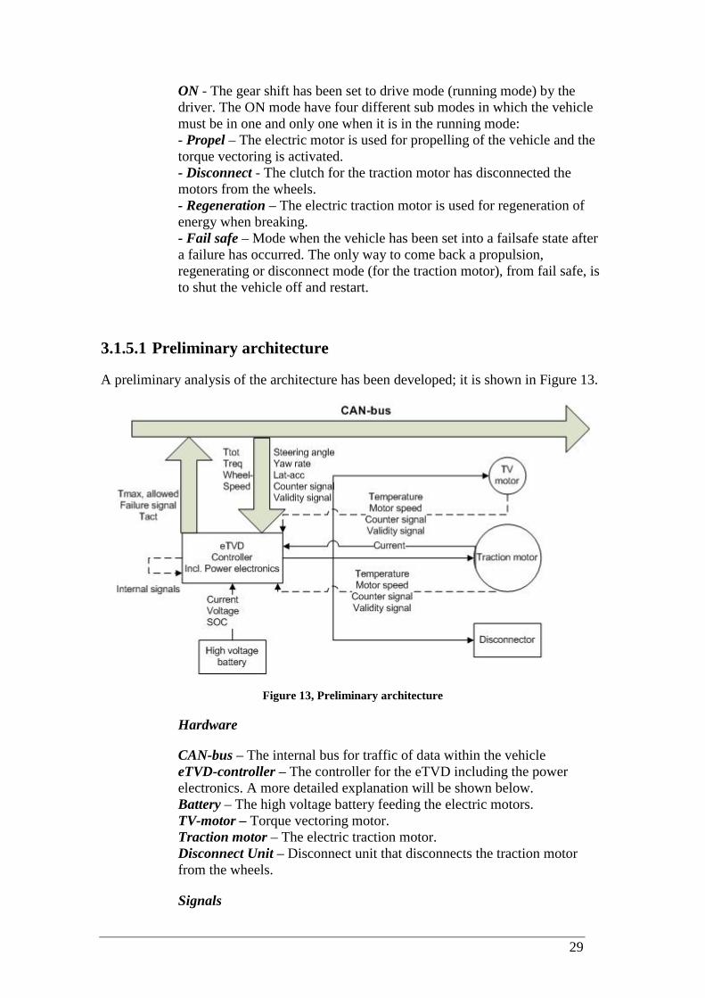
3.1.5.1 Preliminary architecture
A preliminary analysis of the architecture has been developed; it is shown in Figure 13.
Figure 13, Preliminary architecture
Hardware
CAN-bus – The internal bus for traffic of data within the vehicle eTVD-controller – The controller for the eTVD including the power electronics. A more detailed explanation will be shown below. Battery – The high voltage battery feeding the electric motors. TV-motor – Torque vectoring motor. Traction motor – The electric traction motor. Disconnect Unit – Disconnect unit that disconnects the traction motor from the wheels.
Signals

30
Ttot – The requested torque from the driver. Not specified if it should be from combustion engine or electric motor. Treq – Calculated torque request for the electric traction motor. Calculated by the main ECU. Wheel speed – The wheel speeds are given from the ABS sensors. Steering angle – Angle of the steering wheel. Yaw rate – The acceleration of the vehicle around its on middle, in terms of rotating. Lat-acc – The acceleration of the vehicle to the left or right. Traction motor speed – The motor speed, necessary in order to control the torque distribution and avoid over speeding. Torque vectoring motor speed – The motor speed is needed in order to control the torque distribution. Temperature – The temperature of the power electronics, traction motor and torque vectoring motor. Current of the PE– The internal current in the power electronics. Counter signal – A counter signal from each of the signal has been added, this in order to see if a value on the signal is an updated value or an old value, still sent because of lack of new value. For each time a new signal is sent, the counter should increase. Validity signal – A flag that shows if the value of the signal is to trust. Current of battery – The current flowing into/out from battery. Voltage of battery – The voltage of the battery. SOC – State of charge in the battery. Tmax, allowed – The maximum torque that the traction motor can give momentary. A signal for the main ECU of the vehicle, so it can recalculate the torque distribution. A reduction of torque can happen due to overheating of power electronics e.g. Tact
Also the current to the traction motor shall be measured. The signal T
– Actual torque given by the traction motor to the wheels. Failure signal – A flag signal, informing the rest of vehicle that a failure has occurred.
tot
Steering angle, yaw rate and lat-acc is used to calculate the torque (and thereby the current) that needs to be applied by the torque vectoring motor. Advanced control algorithms might require additional CAN-signals (or measured signals) for the control, however, a basic control scheme should be possible to develop with the above mentioned signals.
could be used for algorithms that will be used to determine if any of the propulsion sources (i.e. ICE or electric motor) is applying too much torque; that is if a failure has occurred.

31
A more detailed look into the eTVD controller and power electronics block is shown below, Figure 14, The ECU/power electronics block. All the signals are explained above, except for PWM, which is the signal from ECU to the power electronics.
Figure 14, The ECU/power electronics block

32
3.1.5.2 Functional safety requirement
This chapter present the requirements needed in order to fulfil the safety goals. All values on acceleration levels, times, temperatures etc, are just examples and should not be given too much attention – correct values for such requirements must be evaluated very carefully.
(A, B etc. are the safety goals and A1, B1 etc. are the requirements)
A: “For speeds >15km/h: The eTVD should not cause sudden unwanted acceleration >1m/s2
A1 – An accurate T
for more than 500ms, in either direction.” – ASIL C
req
A2 – An accurate wheel speed signal shall be received – ASIL C
signal shall be received – ASIL C
A3 – An accurate Ttot
A4 – An accurate value of the applied voltage to the propulsion motor must be measured – ASIL C
signal shall be received – ASIL C
A5 – The power electronics (control software) must be able to detect an unwanted vehicle acceleration level higher than 1 m/s2
A6 – The power electronics (control software) must be able to convert a requested torque level to an applied level of propulsion motor voltage with an accuracy that don’t leads to unwanted acceleration levels higher than 1 m/s
based on given input signals – ASIL C
2
A7 – The power electronics shall be able to control the voltage to the propulsion motor with an accuracy that don’t leads to unwanted acceleration levels higher than 1 m/s
for more than 500ms – ASIL C
2
B: “For speeds <15km/h: The eTVD should not cause sudden unwanted acceleration >0.75 m/s
at speeds > 15km/h – ASIL C
2
B1 – An accurate T
for more than 500ms, in either direction.” – ASIL A
req
B2 – An accurate wheel speed signal shall be received – ASIL A
signal shall be received – ASIL A
B3 – An accurate Ttot
B4 – An accurate value of the applied voltage to the propulsion motor must be measured – ASIL A
signal shall be received – ASIL A
B5 – The power electronics (control software) must be able to detect an unwanted vehicle acceleration level higher than 0.75 m/s2
B6 – The power electronics (control software) must be able to convert a requested torque level to an applied level of propulsion motor voltage with an accuracy that don’t leads to unwanted acceleration levels higher than 0.75 m/s
based on given input signals – ASIL A
2 for more than 500ms – ASIL A

33
B7 – The power electronics shall be able to control the voltage to the propulsion motor with an accuracy that don’t leads to unwanted acceleration levels higher than 0.75 m/s2
C: “Turns: The necessary steering wheel correction needed to compensate for a fault in torque vectoring must not exceed 15 degrees or 50 degrees/s.” – ASIL A
at speeds > 15km/h – ASIL A
C1 – An accurate wheel speed signal shall be received – ASIL A
C2 – An accurate steering angle signal shall be received – ASIL A
C3 – An accurate yaw rate signal shall be received – ASIL A
C4 – An accurate lat-acc signal shall be received – ASIL A
C5 – It shall only be possible to apply voltage to the TV-motor if the there is a wheel slip, medium or high lateral acceleration, high lateral dynamic and/or large body slip angle. – ASIL A
C6 – With the given input signals it must be possible to determine if the TV-system applies a yaw moment which is as close to the driver request so that the driver don’t have to compensate this yaw moment with more than 15 degrees steering angle and at a higher rate than 50 degrees/s – ASIL A
C7 – The ECU of TV-motor power electronics shall see if the current measured is equal to the calculated current to the accuracy so that C6 I fulfilled. – ASIL A
D: “Temperature: The power electronics should not cause too much heat due to lack of cooling. Temperatures above 70 ºC are not allowed” – ASIL B
D1 – An accurate temperature signal shall be received – ASIL B
D2 – The ECU for power electronics must be able to control the following if the temperature is rising above 60 ºC; – ASIL B
1. It should increase the cooling 2. Decrease the voltage applied to the motor 3. Disconnect
E: “Temperature: The temperature in the traction motor or torque vectoring motor should not be above 150 ºC.” – ASIL B
E1 – An accurate temperature shall be measured – ASIL B
E2 – The ECU for power electronics must be able to control the following if the temperature is rising above 120 ºC; – ASIL B
1. It should increase the cooling 2. Decrease the voltage applied to the motor 3. Disconnect
F: “Over voltage: The voltage in the traction motor should not be increased above 400V due to over speeding of traction motor” – ASIL B
F1 – An accurate wheel speed signal shall be received – ASIL B

34
F2 – The disconnect unit shall disconnect for speeds above 130km/h in order to avoid high voltages and current – ASIL B
A sudden acceleration shall be detected from sensors for wheel speed (ABS). If the driver doesn’t have any intension of accelerate the controller shall try to ramp down the current to the traction motor. If that doesn’t succeed the disconnect unit will try disconnecting the traction motor from wheels. When a total disconnection is done, the car shall be able to run with a reduced speed and a light on the dashboard shall be turned on, to notice the driver that something has happened. As soon as the driver has rebooted the system, the controller shall do a self test to see if the system is back on track again. If not, the car will return to fail safe mode and the driver has to take the car to a workshop.
3.1.5.3 Evolved safety concept
In order to improve the safety and lower the ASIL´s for safety goal A, by decomposition, it should be added an extra algorithm in the battery microprocessor which should listen for rolling counters from the other signals to the battery. If one or many of the signals rolling counter should stop being updated the battery should, after 2 sec, stop the current flow to the power electronics for both electric motors and even the disconnect unit, which automatically disconnect if lack of voltage.
Since safety goal B has a lower ASIL than safety goal A, and is more or less the same, it should automatically be redundant by the solution above. For the other safety goals, the disconnect unit will also be used, as a last exit.
No further redundancy will be needed since there is a clear relation between many of the signals. By knowing three signals, the fourth one can detected, if it has a strange or incorrect value, i.e. redundancy in between.

35
4 Conclusion The work of ISO26262 really shows a full and mature way to implement and obtain a failsafe system for the E/E-system within the car. It controls the way of working from the start of an idea to a finished product, including a lots of tests and validations on its way. By following the steps in the implementation process it is easy to see and follow its requirements.
This report covers a study of Haldex eTVD, study of ISO26262 and an implementation of the concept phase (part 3 of ISO26262). The implementation started with an analysis of the eTVD in order to find the items and then a study of the hazards and risks of the system. This resulted in a huge tree of situation that may occur for the driver. From that tree, a table of the hazards can be derived. That is a table including exposure, severity and controllability, and out from them give the hazards an ASIL. The safety goals can then be stated out from the table. From the safety goals the functional safety concept can be started. It contains safety requirements, architecture of the item and an evolved architecture.
This report doesn’t cover a fully implementation of ISO26262. It is more a first try and guideline to get an idea of how it shall be done.
5 Further work The continuing work on this task is to implement the part 4 of the ISO26262 to the eTVD. The task is then to look more into the hardware and software structure and to see what can be improved in order to make it more failsafe. When having a strong construction, tests should be done. If it passes, the production can be started. Then it can be started all over again, for a new product improvement.

36
6 References [1] Gerhard Griessnig, Standardization activities about functional safety in
automotive, ProSE-Networking Session, (AUTOSAR, ISO 26262, CESAR) ICT 2008, Nov 26th
[2] Jonathon Ramsey, Vectoring: The future of AWD, Autoblog.com Oct 14
2008
th 2007 http://www.autoblog.com/2007/10/14/torque-vectoring-the-future-of-awd/
[3] Joacim Bergman, Per Johannessen, Daniel Larsson, ISO/DIS 26262 Funktionssäkerhet i vägfordon, Seminar Dec 2nd 2009
[4] Wikipedia, Failure Mode and Effects Analysis, March 8th 2010, http://en.wikipedia.org/wiki/Failure_mode_and_effects_analysis
[5] ISO/TC 22/SC 3, ISO/DIS 26262, March 28th
[6] IVF-skrift 93816, FMEA – Feleffektanalys
2009
http://extra.ivf.se/lean/pdf/kvalitet/FMEA.pdf

37
7 Appendix
7.1 Tree of situations that may lead to a failure The yellow boxes are the intension; what the driver has for intension. Accelerate longitudinal or lateral, or them both. + acc is, for longitudinal, forward.
The green boxes are what the result is. What actually happened?
The blue boxes are amplitude of what happened. Is the acceleration higher or lower than expected?
The red boxes are in which situation this happened.

Straight ahead
-Right
Standing still
High speed
Low speed
+ Left
Low speed
Standing still
High speed

Lat
-Right
Incorrect sign
Default (Utebliven)
Correct sign
Lower
High speed
Standing still
Low speed
High speed
Standing still
Low speed
High speed
Standing still
Low speed
High speed
Standing still
Heat
Explosion (can be
caused by over
charging)
Fret injuries
Fire

+ Left
Incorrect sign
Default (Utebliven)
Correct sign
Lower
Higher
High speed
High speed
Standing still
Low speed
Standing still
Low speed
Standing still
Low speed
High speed
Standing still
Low speed
High speed
Hazards
Failmode

Acceleration
0 acc
Default (Utebliven)
+
positive
-
Negative
What´s the intension?
Result
, higher or lower than expected
Situation
Higher
Standing still
Low speed
High speed
Standing still
Low speed
High speed
Standing still
Low speed
High speed
Low speed
High speed

Long
-acc
Incorrect sign
Defau
Correct sign
Lower
Higher
Default (Utebliven)
Standing still
Low speed
High speed
Amplitude, higher o
Standing still
Low speed
High speed
High speed
Low speed
Standing still
Standing still
Low speed
High speed
Squash injuries,
by rotation
+ acc
Correct sign
Lower
Higher
Incorrect sign
Default (Utebliven
Standing still
Low speed
area
High speed
area
High speed
Low speed
Standing still
Standing still
Low speed
Standing still
High speed
Low speed

44