hazardous waste facilty closure plan · pdf filecalifornia environmental protection agency eci...
TRANSCRIPT

California Environmental Protection Agency ECI Fontana Facility Nov 30 2006
Department of Toxic Substances Control
DTSC 1179 (8-11-04) Standardized Permit Application Instructions
1
HAZARDOUS WASTE FACILTY CLOSURE PLAN
November 30, 2006
ECOLOGY CONTROL INDUSTRIES 13738 SLOVER AVENUE
FONTANA, CA 92337

TABLE OF CONTENTS SECTION A - FACILITY IDENTIFICATION.................................................................... 3 SECTION B - FACILITY LOCATION.............................................................................. 5 SECTION C - FACILITY DESIGN (CONTAINERS & TANKS)....................................... 7 SECTION D - DESCRIPTION OF HAZ WASTE MGT UNITS ...................................... 11 SECTION E - ESTIMATE AND MGT OF MAXIMUM INVENTORY.............................. 13 SECTION F - EQUIPMENT AND STRUCTURE DECON PROCEDURES................... 15 SECTION G - CONFIRMATION SAMPLING PLAN FOR CONTAINMENT ................. 17 SECTION H - SOIL SAMPLING PLAN......................................................................... 19 SECTION I - ANALYTICAL TEST METHODS ........................................................... 20 SECTION J - CLOSURE COST ESTIMATE……………………………………………….21 SECTION K - CLOSURE PERFORMANCE SAMPLING & MONITORING ................. 25 SECTION L - REMOVAL & CLEANUP PROCEDURES .............................................. 25 SECTION M - IMPLEMENTATION SCHEDULE .......................................................... 26 SECTION N - HEALTH & SAFETY PLAN………………………………………………… 27 SECTION O - SITE SECURITY………………………………………………………………36 SECTION P - CLOSURE CERTIFICATION…………………………………………………37
LIST OF ATTACHMENTS
ATTACHMENT 1. USGS TOPOGRAPHIC MAP ATTACHMENT 2. FLOODPLAIN MAP ATTACHMENT 3. FACILITY PLOT PLAN ATTACHMENT 4. PROCESS FLOW DIAGRAM ATTACHMENT 5. HAZARDOUS WASTE LABEL ATTACHMENT 6. WASTE PROFILE SHEET (FOR REMOVED SOIL IF REQUIRED) ATTACHMENT 7. CLOSURE PLAN-CONFIRMATION SOIL SAMPLE LOCATIONS ATTACHMENT 8. WASTE ACCEPTANCE PROFILE TESTING REQUIREMENTS ATTACHMENT 9. WEATHER DATA AND WEATHER MAPS ATTACHMENT 10. ECI VISITOR SECURITY PROCEDURES-HSE 903 ATTACHMENT 11. SCAQMD REGULATION XI RULE 403 ATTACHMENT 12. SCAQMD REGULATION XI RULE 1166 ATTACHMENT 13. SHAW ENVIRONMENTAL SOIL SAMPLING PLAN
2

A. FACILITY IDENTIFICATION List the following information about the facility: 22CCR 66270.13
1. Facility name: ECOLOGY CONTROL INDUSTRIES
2. EPA ID number: CAD982484933
3. Address (street, city, state, Zip code):
13738 Slover Avenue, Fontana, CA 92337 4. Mailing Address (street, city, state, zip code) 19500 Normandie Avenue, Torrance, CA 90502
5. Telephone number: (310) 420-0285 or (310) 767-3240 6. Contact Person(s): Steve Smith or Jerry White 7. Preparer of Standardized Closure Permit Application.
a. Name(s) and title(s) of the person(s) responsible for preparation of the operation plan:
Jerry White - Safety & Compliance Manager
b. Work telephone numbers of the person(s) responsible: (310) 767-3240
c. Dated, original signatures of the person(s) responsible:
Signature: ____________________________ Date:_______________ Signature: ____________________________ Date: _______________ 8. Facility Operator: ECOLOGY CONTROL INDUSTRIES, INC 9. Facility/Business Owner: Mr. Ronald Flury
10. Landowner: J.N. Pocock, Landlord
3

California Environmental Protection Agency Department of Toxic Substances Control
Standardized Permit Application Instructions
4
OWNER/OPERATOR PAGE 11. OWNER/OPERATOR SIGNATURES AND CERTIFICATION AND DISCLOSURE
STATEMENT
Give original, dated signatures of the following: 22CCR 66270.10(a)&(b), 66270.11(d), 66270.14(a)
a. Facility owner.
Signature____________________________Date__________
b. Facility operator, including facility operator certification required under Title 22, CCR, Section 66270.11(d)
Signature____________________________Date__________
"I certify under penalty of law that this document and all attachments were prepared under my direction or supervision in accordance with a system designed to assure that qualified personnel properly gather and evaluate the information submitted. Based on my inquiry of the person or persons who manage the system, or those persons directly responsible for gathering the information, the information submitted is, to be the best of my knowledge and belief, true, accurate, and complete. I further certify that the property owner has been informed that a hazardous waste facility will be operated on the premises. I am aware that there are significant penalties for submitting false information, including the possibility of fine and imprisonment for knowing violations".
All facilities shall complete and submit a Disclosure Statement, Form DTSC
8430. (Health and Safety Code 25112.5) except for the following, as excerpted from Senate Bill No. 27:
"Notwithstanding Section 25112.5, a disclosure statement for an application for a series C standardized permit, as specified in Section 25201.6, shall consist of documentation of any convictions, judgments, settlements, or orders resulting from an action by any local, state, or federal environmental or public health enforcement agency concerning the operation of the facility within the last three years, as documents would be available under the California Public Records Act (Chapter 3.5 (commencing with Section 6250) of Division 7 of Title 1 of the Government Code) or the Information Practices Act of 1977 (Chapter 1 (commencing with Section 1798) of Title 1.8 of Part 4 of the Civil Code), except that the owner or operator

California Environmental Protection Agency Department of Toxic Substances Control
Standardized Permit Application Instructions
5
of a facility issued a series C standardized permit shall make the information specified in Section 25112.5 available to the Department upon request"

California Environmental Protection Agency Department of Toxic Substances Control
Standardized Permit Application Instructions
6
B. FACILITY LOCATION 1. DETAILED TOPOGRAPHIC MAP Submit a topographic map showing a distance of 2000 feet around the facility at a scale of 1 inch equal to not more than 200 feet. The map must include contours sufficient to clearly show the pattern of surface water flow in the vicinity of and from each operational unit of the facility (e.g., contours with an interval of 5 feet, if relief is greater than 20 feet, 2 foot intervals if the relief is less than 20 feet, or an interval of 2 feet, if relief is less than 20 feet). Owners and operators of hazardous waste management facilities located in mountainous areas should use larger contour intervals to adequately show topographic profiles of facilities. The map must also include the following: 22CCR 66270.14(b)(18)
a. Map scale and date: See Attachment 1. Topographic Map
b. 100-year floodplain area: See Attachment 2. Floodplain Map
c. Surface waters including intermittent streams: See Attachment 2. Floodplain Map d. Surrounding land uses (residential, commercial, agricultural, recreational):
See Attachment 3. Facility Plot Plan
e. A wind rose (e.g., prevailing wind-speed and direction). See Attachment 3. Facility Plot Plan
f. Orientation of the map (north arrow): See Attachment 3. Facility Plot Plan
g Legal boundaries or the hazardous waste management facility site:
See Attachment 3 Facility Plot Plan. The leased boundary lies along the fence line indicated on the plot plan. Please note that the fence line is marked as the property boundary.
h. Access control (fences, gates):
See Attachment 3 Facility Plot Plan. The onsite traffic routes are indicated on the Facility Plot Plan. Access and egress is accomplished from the entrance at Slover Ave. on the southern end of the facility. There are no other gates or access points to the facility.
9. Injection and withdrawal wells both onsite and offsite:
There are no injection or withdrawal wells located on the site. Ecology Control Industries (ECI), requested information on offsite wells within a 2,000-foot radius around the facility from the Department of Water Resources, (DWR), Southern District in Glendale, California on September 26, 2002. There are no known wells within the 2,000-foot radius of the Facility. Two groundwater wells are located East of the Facility as follows:
Well 01S/05W-21D02, 9715 Alder Ave. Bloomington, CA, approx. 5 miles Northeast, municipal, irrigation and industrial use:
Well at 18850 Orange Street, Bloomington, CA, approx. 5.5 miles East, public water supply.

California Environmental Protection Agency Department of Toxic Substances Control
Standardized Permit Application Instructions
7
In addition to the information supplied by DWR, Hart Crowser checked the DWR online groundwater resources web site at: http://wdl.water.ca.gov/gw_data/hyd/Rpt_Bas_Well_AllCal.asp No wells were identified within the 2,000-foot radius of the facility. Hart Crower also requested groundwater well information from the California Regional Water Quality Control Board, Santa Ana Region (CRWQCB). According to information provided by Mr. Cameron Scrimi of the CRWQCB, there are no wells identified within Township 1S, Range 6W, Sections 21, 27, and 28 which include the facility. Information was also requested from the Fontana Water Company. This company owns 30 wells in the Fontana area. According to the Fontana Water Company, as of July 2006, there are no wells owned by their company or any public agency within the 2,000-foot radius of the Facility. The nearest well to the Facility is:
Well 1S/6W-F21, Corner of Slover Ave. and Live Oak Avenue, Fontana, CA, approx. 1.5 miles East, it is designated for municipal use.
10. Buildings; transfer, treatment, or storage operations; or other structure (recreation areas,
run-off control systems, access and internal roads, storm, sanitary and process sewerage systems, loading and unloading areas, fire control facilities, etc.): See Attachment 3. Facility Plot Plan which shows the required information. The drawing also references other drawings utilized during the preparation of the facility plot plan. The property is currently leased by ECI from Superior Trailer. The facility boundaries are indicated on the plot plan.
11. Barriers for drainage or flood control:
The nearest storm drain is located at the intersection of Slover Ave. and Mulberry Street. There are no drains, swales, curbs, culverts, or other rainwater controls located in the Facility. The tank processing areas, including the tank staging pad, tank rinse pad, and rinsate holding tanks, are equipped with secondary containment that will capture rain water. All rain water that falls inside these process areas is pumped into the rinsate holding tank and managed along with the rinsate process water.
12. Location of operational units within the hazardous waste management facility site,
where hazardous waste was transferred, treated, or stored (include equipment cleanup areas): See Attachment 3. Facility Plot Plan Throughout the Standardized Permit Application, there will be requests for information to be shown on design drawings, diagrams, plans, etc. The following is a listing of the minimum necessary plans, diagrams, and drawings that will be required to be included. In order to consolidate information, if possible, use one type of diagram or plan for the entire application rather than a separate one for each section. For example, the piping layout can be used for information requested in the container section and the tank section rather than a separate piping layout for each section.

California Environmental Protection Agency Department of Toxic Substances Control
Standardized Permit Application Instructions
8
C. FACILITY DESIGN The information in this section is more applicable to the closure plan for facility that is applying for a new hazardous waste facility permit or a permit renewal. ECI initially filed for a permit at the facility but withdrew the application and opted to close the facility. The information contained in this section of the plan will give the reader a good understanding of the extent of the facility and an appreciation for how the facility operated. 1. Process Flow Diagram (when it was operational) shows the path of each waste stream from the point of entrance into the facility to its exit from the facility. The process flow diagram includes each point where the waste stream physically and/or chemically changes and show points where samples are collected (sampling points will be indicated in the waste analysis plan). Also shows any equipment that is used to move the waste stream such as pumps, blowers, belts, etc. See Attached Process Flow Diagram Description of Process Flow Petroleum Storage tanks were pumped clean and rinsed in the field prior to being
loaded on a truck for transport to the ECI Fontana Facility. Usually an agency such as the local fire department, environmental department, public works agency, or some other designated hazardous material agency, had a representative at the loading site who would oversee the cleaning, excavation, and loading of the tank. The inspector insured that flammable vapors were reduced to a safe level of less than 10% of the lower explosive limit (LEL) before certifying that a tank was “gas free” and ready for transport. The inspector supervised the loading operation to insure that the tank removal was performed in a safe and environmentally responsible manner. He may also have supervised additional operations such as soil sampling, soil removal, and back fill operations, to insure that those operations were performed in accordance with applicable standards and procedures.
The tanks were considered empty when all wastes had been removed that could be
removed using the practices commonly employed to remove materials from that type of container and no more than 2.5 centimeters (one inch) of residue remained on the bottom of the container, or no more than .3% by weight of the total capacity of the container remains in the container (40CFR 261.7). These tanks were considered to be “RCRA empty” even though they may contain some residue. That is why it was necessary to transport the tanks to the ECI facility for a more thorough decontamination.
ECI received tanks and piping that were designated as Non RCRA hazardous wastes
(RCRA empty containers) and cleaned them so they met “California-empty” standards. The tanks were then rendered non-hazardous according to California requirements.
2. Rinsate Tanks. Provide the following manufacturer's design specifications for each Rinsate tank remaining on-site: (22 CCR 66265.191 & 194, 66270.14(b)(19), & 66270.16(a) - (b)).
(1) Internal and/or external dimensions in feet and inches. (22 CCR 66265.191(b)(1)).

California Environmental Protection Agency Department of Toxic Substances Control
Standardized Permit Application Instructions
9
External Dimensions: 5200 gallon tank 14' Diameter X 7' Height 1850 gallon tank 6' Diameter X 9' 8" Height Note: 1850 gallon tank was not used. It was a back-up.
(2) Internal design capacity in gallons. (22 CCR 66265.191(b)(1)).
Capacity: Per Coory Engineering 5200 gallons (4900 gallon straight wall capacity) 1850 gallons ( 1700 gallon straight wall capacity)
(3) Shell thickness such as wall, top, and bottom in inches. (22 CCR
66265.191(b)(1)). The following are the structural calculations and Barlow
thickness. Please note that the tank referred to as a 5200 gallon tank in the engineer’s structural calculations is now called a 4900 gallon tank by the manufacturer and so the structural data sheet with Barlow thickness data for the 5200 gallon tank is provided on the sheet with the 4900 Gal. (upright heading). The tank referred to as an 1850-gallon tank in the engineer’s calculations is now referred to by the manufacturer as a 1700 gallon tank. The structural calculations for the 1850-gallon tank are indicated on the sheet with the 1700 Gal. (upright heading). Barlow thickness is in inches.
(4) Operating pressure of the tank in psi from daily operating records, if applicable. (22 CCR 66265.191(b)(1)). Pressure: Ambient pressure
(5) Manufacturer's design specification for the tank structural support and installation. (22 CCR 66265.191(b)(1)).
See Attachment 7. Tank Specifications
(6) Manufacturer's design specification for tank roof, if applicable (22 CCR 66265.191(b)(1)). See Attachment 7. Tank Specifications
(7) Age of each tank from the operating records of the facility. (22 CCR 66265.191(b)(4)). Age: 13 years
(8) Operating temperature of each tank in degrees Fahrenheit from
operating records. (22 CCR 66265.191(b)(5)(A)). Temperature: Ambient temperature.
b. Rinsate Tank Construction (i.e., manufacturer's specification). (22 CCR
66265.191(b)(3), 66270.16(a) & (l)):
The tanks are molded from high-density cross linked polyethylene. The resin used is Marlex CL-200 YJN as manufactured by Philips Petroleum Company, Plastics Division or Paxon 7004 as manufactured by Paxon, Inc. or of resins of equal physical and chemical properties

California Environmental Protection Agency Department of Toxic Substances Control
Standardized Permit Application Instructions
10
c. Is the tank lined or coated? YES_____NO_X___. If yes, complete the following:
Describe the lining and/or coating material used inside or outside each tank from manufacturer's specifications or scientific or engineering specifications.
(1) Provide the interior lining material specifications and thickness, if
applicable. N/A (2) Provide the exterior coating material specifications and thickness, if
applicable. N/A
d. Provide the engineer's assessment of the base foundation for each tank which considers full tank load, flotation or dislodgement of tank and frost heave. In addition include the following: (22 CCR 66265.193(c)(2), 66270.14(b)(19), 66270.16(a), & (k)).
(1) Describe the sub-foundation work and seismic reinforcement
measures such as soil compaction, piles, etc. The tanks are set on a 6-inch thick concrete pad set on a 4-inch
crushed rock base and a 1-inch (minimum) engineered backfill base compacted to a minimum of 90% relative density per ASTM D1557 to prevent subsidence of the foundation from potential liquefaction due to a seismic event. In this way, the foundation is also protected from subsidence that could potentially occur from excessive water infiltration into adjacent soils during a prolonged rainfall event.
(2) Provide information on the materials, methods of construction and
imperviousness to hazardous waste. The tank pad is composed of a 6” thick, steel reinforced concrete pad that was single poured.
(3) Describe the fire protection rating of the tank foundation from
contractor's specifications, scientific and engineering references, if applicable.
The concrete pad is rated to resist a minimum of a 2-hour fire event as per California Unified Fire Code.
(4) Is the tank outdoors?
YES__X__NO_____. If yes, provide the following:
Describe the measures taken to protect the tank foundation from cracking or eroding due to extreme weather conditions. The concrete pad is also resistant to extreme weather conditions (excessively low or high temperatures, frosting, freezing conditions) due to the presence of adequate reinforcing steel which has been provided to prevent cracks from developing in the concrete slab.
California Environmental Protection Agency Department of Toxic Substances Control
Standardized Permit Application Instructions
11
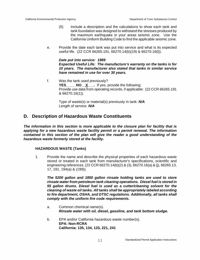
(5) Include a description and the calculations to show each tank and tank foundation was designed to withstand the stresses produced by the maximum earthquake in your areas seismic zone. Use the California Uniform Building Code to find the applicable seismic zone.
e. Provide the date each tank was put into service and what is its expected
useful life. (22 CCR 66265.191, 66270.14(b)(19) & 66270.16(l)). Date put into service: 1989 Expected Useful Life: The manufacture’s warranty on the tanks is for 10 years. The manufacturer also stated that tanks in similar service have remained in use for over 30 years.
f. Was the tank used previously?
YES_____NO__X___. If yes, provide the following: Provide use data from operating records, if applicable: (22 CCR 66265.191 & 66270.16(1)).
Type of waste(s) or material(s) previously in tank: N/A Length of service: N/A
D. Description of Hazardous Waste Constituents The information in this section is more applicable to the closure plan for facility that is applying for a new hazardous waste facility permit or a permit renewal. The information contained in this section of the plan will give the reader a good understanding of the hazardous waste formerly stored at the facility. HAZARDOUS WASTE (Tanks)
1. Provide the name and describe the physical properties of each hazardous waste stored or treated in each tank from manufacturer's specifications, scientific and engineering references. (22 CCR 66270.14(b)(2) & (3), 66270.16(a) & (j), 66265.13, 17, 191, 194(a) & (199)).
The 5200 gallon and 1850 gallon rinsate holding tanks are used to store
rinsate water from petroleum tank cleaning operations. Diesel fuel is stored in 55 gallon drums. Diesel fuel is used as a cutter/cleaning solvent for the cleaning of waste oil tanks. All tanks shall be appropriately labeled according to fire department, OSHA, and DTSC regulations. Additionally, all tanks shall comply with the uniform fire code requirements.
a. Common chemical name(s). Rinsate water with oil, diesel, gasoline, and tank bottom sludge.
b. EPA and/or California hazardous waste number(s).
EPA: Non-RCRA California: 135, 134, 133, 221, 241

California Environmental Protection Agency Department of Toxic Substances Control
Standardized Permit Application Instructions
12
c. Specific gravity. The rinsate waste forms three layers.
An oil layer on top with a specific gravity less than 1. The aqueous layer is the predominant layer that comprises over 90 % of the tank contents. This layer has a specific gravity of approximately 1. The sludge layer accumulates on the bottom of the tank and may have a specific gravity between 2.1 and 2.65.
d. Vapor pressure, if applicable. N/A
e. Storage temperature, if applicable. Ambient Temperature
f. Flame point/auto-ignition temperature, if applicable. Non-Flammable, the
flash point is greater than 140 degrees Fahrenheit.
g. Expected number of layers when compatible hazardous waste with different specific gravities are stored together, if applicable. The rinsate tank contents are usually composed of 3 layers; an oil layer on top, an aqueous water layer in the middle, and a sludge layer on the bottom.
h. Compatibility of hazardous wastes with tank materials of construction, and
with liner and/or coating materials. The rinsate water is compatible with the polyethylene tank material per
the manufacturer. The tank integrity has not been compromised in over 13 years of service.
Briefly summarize the procedures the facility will use to achieve closure (A closure is a process where all of the facility's hazardous waste is removed and the facility is decontaminated).
The following is brief summary of the procedures the facility will use to achieve clean closure: 1. Remove any existing petroleum storage tanks in inventory. Once cleaned, processed
tanks will be transported to an approved landfill or salvage facility. (this has been completed there are currently no underground fuel storage tanks on the site)
2. All remaining hazardous waste including waste contained in the roll-off bins and the rinsate tank will transported to the appropriate disposal facilities as discussed in Section C. (this has been completed there is currently no hazardous waste stored on the site)
3. All structures and equipment will be decontaminated by pressure washing as described in Section F. Rinsate water will be collected, tested, and transported to an approved recycling facility.
4. To demonstrate the ability of the facility to meet clean-up standards, confirmation samples (chip, wipe or cleaning solution) will be obtained from equipment and structures.
5. Surface and subsurface confirmation samples will be collected and analyzed

California Environmental Protection Agency Department of Toxic Substances Control
Standardized Permit Application Instructions
13
according to the sampling protocol provided in Sections E. and F. No contamination is anticipated; however, if contamination is found, an Excavation Proposal will be prepared and submitted to the Department of Toxic Substances Control.
6. An independent engineer submits a clean closure certification report. E. MAXIMUM INVENTORY ESTIMATES Ordinarily when applying for a hazardous waste facility permit the applicant would estimate the maximum quantity of hazardous waste that will be on the site at any one time for the purposes of generating a closure cost estimate. In this case at the time the closure plan was revised there was no hazardous waste being stored at the site. Hazardous waste will be generated when the equipment and infrastructure formerly used is decontaminated. An estimate of the maximum amount of hazardous waste to be generated during the closure is outlined below. (66265.112(b)(3) & (4)) This section of the closure plan describes the maximum hazardous waste inventory that are going to be held on site at any one time over the active life of the facility. The maximum inventory should be a sum of all hazardous waste capacity and waste generated from closure activities. 1. Give an estimate of maximum waste inventory.
a) Maximum hazardous waste in all containers (A sum of all volumes given in section IV A.1.b.). Currently no hazardous waste in containers on the site Currently no petroleum storage containers on the site
b) Maximum hazardous waste in all tanks (A sum of all volumes given in section V A.1.b.).
Rinsate Tanks: 5,200 gallon rinsate water tank = Residual only <55gl 1850 gallon rinsate water tank = “Dry” c) Other wastes stored on facility. None
2. Provide an estimate of waste that will be generated from closure activities (i.e. wash water generated, sand from sand blasting, etc.). Note: The following figures can be used to estimate the quantity of waste generated from closure activities.
High-Pressure Washing 10 gallons of wash water generated per 1 drum cleaned. 50 gallons of wash water generated for 1 pump & lines cleaned. 4 gallons of wash water generated per square foot of surface cleaned. Steam Cleaning 4 gallons of wash water generated per square foot of surface cleaned. Sand Blasting 0.62 gallons of sand per square foot of surface cleaned. a) Calculate the amount of waste generated from the decontamination of containers and
container areas. N/A. Roll-off bins will not require decontamination; they are lined with

California Environmental Protection Agency Department of Toxic Substances Control
Standardized Permit Application Instructions
14
visqueen prior to receiving waste.
b) Calculate the amount of waste generated from the decontamination of tanks and tank areas.
Rinsate Tank Decontamination Water: 2463 gallons rinsate water from large rinsate tank 954 gallons rinsate water from small rinsate tank 100 gallons from pumps and associated piping 1.50 cubic yards of solids from tank bottom
Structure and Equipment Decontamination Water: 14,420 gallons (3,605 square feet x 4gallons/foot) from cleaning Tank Holding/Staging Pad 3,200 gallons (800 square feet x 4gallons/foot) from cleaning Tank Cleaning Pad 4,860 gallons (1,215 square feet x4 gallons/foot) from cleaning secondary containment area 200 gallons from cleaning equipment e.g. shovels
Note: ECI owned Vacuum Trucks/Tanks and/or Crown tanks will be used to remove the Decontamination Water per appropriate manifest procedures.
c) Calculate the waste generated from the decontamination of other areas. None
3. Off-site Receiving Waste Management Facility: 45.3 Miles Thermal Processing Systems (TPS) 12328 Hibiscus Rd. Adelanto, CA 92301 Profile Testing Requirements: See Attachment 8. 4. Manifesting and Authorized Hauler: Ecology Control Industries, Waste Hauler #1533 F. EQUIPMENT AND STRUCURE DECONTAMINATION PROCEDURE 1. Describe how the final batch of waste will be removed from the facility or treated from the facility. The wastes can be removed/treated by the following methods:
a) Processing the waste through the facility's process. There are currently no underground fuel storage tanks on the site that require processing.
b) Taking the waste off-site to a treatment facility.
There is currently no hazardous waste on the site.
c) Taking the waste off-site to a disposal facility.
There is currently no hazardous waste on the site.

California Environmental Protection Agency Department of Toxic Substances Control
Standardized Permit Application Instructions
15
d) Other. None.
DECONTAMINATION PROCEDURES 2. This section of the closure plan identifies all structures, buildings, and equipment that the facility plans to decontaminate. Circle all equipment, structures, and buildings the facility plans to decontaminate. Identify all
circled items on a plot plan. If an item cannot be identified on the plot plan, give a brief description including the number, size and material of construction. See Attachment 3.
a) Tanks: Rinsate Tank
b) Containers. Roll-Off bins are lined with visqueen; therefore decontamination is
not necessary.
c) Treatment Process Units (e.g., evaporators, metal recovery). N/A
d) Secondary Containment Systems. For Rinsate Tank
e) Floors & Walls of Buildings. N/A
f) Pipes, Pumps, Valves, Hoses. For Rinsate Tank
g) Loading and Unloading Pads. Asphalt Holding Pad, Concrete Processing Pad
h) Equipment (e.g., forklifts, dollies, pallets, shovels).
i) Others.
3. Describe the procedures used to decontaminate equipment, buildings and structures identified in the previous question. The decontamination methods should be selected from the methods given in table 1. The decontamination methods should be selected based on criteria such as waste contaminants, level of contamination and surface materials being cleaned.
Decontamination Procedures The equipment, tank pads and rinsate tank will be decontaminated by a triple rinse pressure washing as follows below. If necessary a degreasing solution such as “simple green” will be utilized.
Rinsate Tank: Tank entry will follow standard confined space entry procedures. 1) Pumps and piping must be drained and blinded prior to tank entry.
2) Prior to tank entry, vapor space will be tested and monitored utilizing a 3 gas confined space meter to assure the atmosphere is safe for entry and continued occupation.
3) The tank entry/decontamination team will consist of a minimum of three people. The job requires a “confined space entry supervisor” to complete the ECI confined space entry permit. A minimum of one “hole watch”, and one entrant are required whenever it is necessary to enter into a tank. Entrants remove contaminated soils and sludge with a shovel or scraping tool. The tank will then

California Environmental Protection Agency Department of Toxic Substances Control
Standardized Permit Application Instructions
16
be triple rinsed with a pressure washer. The rinse water will be pumped to the rinsate holding tank with an air driven diaphragm pump.
4) Upon completion of the cleaning, the tank will be visually inspected for residues. Facility Equipment: Facility equipment such as: pumps, hoses, shovels and piping associated with the rinsate tank, will be triple rinsed on the processing pad. The rinsate water will be collected with a vacuum truck for off-site recycling. Tank Holding Pad & Tank Processing Pad: Both pads will be triple rinsed using a pressure washer or if necessary a steam cleaner. A “simple green” cleaning solution will be utilized on heavily stained areas. The rinsate water will be collected using the above mentioned vacuum truck and transported off-site for recycling.
G. CONFIRMATION SAMPLING PLAN FOR STRUCTURES, EQUIPMENT AND BUILDINGS 1. This section of the closure plan shall describe a sampling plan that will demonstrate the ability of the facility to meet the clean-up standards. There are basically, two clean up levels that are used to achieve clean closure. The two clean-up levels are:
Non-Detect - Non-Detect is the detection limit for a specific analytical method. (e.g., method 8080, Aldrin, 0.004 ug/L). Background - Background clean-up level is applicable only for soil samples and inorganic (metals) constituents. Background clean-up level is the level of inorganic content that exists in natural soil without any outside influence.
If the clean-up levels based on non-detect and background cannot be met, the facility may submit a risk assessment that will provide a new clean-up level that does not pose a substantial present or potential threat to human health and the environment. Note: The following two flowcharts can be used as a general guideline in determining the course of action for the closure operation. The sampling plan is used to verify the effectiveness of the decontamination operation or to demonstrate that no contamination has ever taken place. The sampling should be performed only after a thorough visual inspection and a proper decontamination. There are generally two sampling methods that are used to determine the locations and number of sampling points: biased (judgmental) and statistical (random). They are as follows:
Biased Sampling - Used in situations where locations of point sources of the contamination are known or suspected. For example, a biased sample would be taken from areas that are either visibly contaminated or suspected to be contaminated. Statistical Sampling - Used in situations where there is no information or knowledge available about the sampling area. The statistical sampling method is especially useful for covering large unknown sampling area.
There are four surface sampling methods that are used for the closure of treatment and storage facilities. They are as follows: Wipe Sampling - This method is used for sampling smooth, impervious and solid surfaces such as metal tanks, epoxy coated concrete, vinyl liner, etc. One wipe sample, at a minimum, should be taken from each tank. A typical wipe sample area is 1 square foot. The

California Environmental Protection Agency Department of Toxic Substances Control
Standardized Permit Application Instructions
17
samples should be taken using filter paper or gauze pad moistened with a solvent that will remove the contaminant from the surface. Chip Sampling - This method is used for sampling porous surfaces such as asphalt, concrete and wood. In this method, the surface of the material is chipped out using tools such as a chisel or an electric hammer. The chip sample should have a size approximately 10 cm x 10 cm in area and 1/8 inch in depth. Cleaning Solution Sampling - This method is used for sampling items such as pumps, pipes, filters and equipment. This method is used for sampling parts that are physically difficult to get to or too small to sample individually.
Polychlorinated Biphenyls (PCB) Wipe Sampling - A specific procedure for sampling PCB is available in the EPA document, Field Manual for Grid Sampling of PCB Spill Sites to Verify Cleanup, Interim Report #3, Work Assignment 37.
There is no specific guidance on the number of samples required for sampling structures, equipment, and buildings. However, the sampling number should be large enough to prove that all structures, equipment, and buildings have been properly decontaminated. For each sample and each sample set that is taken at the site, a quality control measure is required to establish the data's quality for each analytical result. Therefore, additional quality control samples are required.
Additional information about sampling methods described above can be obtained from the following EPA guidance document, Compendium of Waste Sampling Procedures, EPA/540/P-91/008.
All sampling should follow the procedure specified in the document, EPA Test Methods for Evaluating Solid Waste, Physical/Chemical Methods, SW-846.
NOTE: The EPA guidance documents may be obtained from National Technical information Services at (703)487-4650 or U.S. EPA, Public Information Center at (415)744-1500. Describe the sampling procedures to be used for sampling buildings, equipment and structures for contamination. The description should discuss the number of samples to be taken, sampling methods, location of sampling points and rationale used for selecting sampling point locations. All structures, equipment and buildings that were identified in section D.1. should be included in the sampling description. Demolition and disposal of the tank pads will only be completed if the analytical results of the concrete or the soil samples beneath the concrete reveal contamination. Background levels will be utilized as clean-up standards for inorganic metals. Non-Detect will be utilized as the clean-up standard for TPH results. Please refer to the Soil Sampling Plan prepared by Shaw Environmental group for details of the soil and concrete sampling that will be conducted. The plan can be found in Attachment 13 at the end of this document. Wipe samples will be taken from the floor walls and roof of each rinsate tank decontaminated (6 samples in total). Wipe samples will also be taken at random from equipment decontaminated e.g. shovels (4 samples in total).

California Environmental Protection Agency Department of Toxic Substances Control
Standardized Permit Application Instructions
18
H. CONFIRMATION SOIL SAMPLING PLAN A soil sampling plan may or may not be required for a facility's closure plan. Soil sampling may be required based on current and/or future conditions of the facility. As discussed in the previous section, either biased or statistical sampling methods can be utilized for the soil sampling plan. Regardless of the chosen sampling method, the soil samples shall be taken from the surface and at a certain depth, typically 1 to 2 foot, from the surface. If the soil is covered, such as under a concrete pad or asphalted surface, soil sampling may be required at the time of the closure depending on the cover condition (i.e. cracks in concrete). The number of samples required depends on conditions such as area to be sampled, degree of contamination and contaminants of concern. For this guidance purpose, a minimum of 4 soil samples is recommended for each storage and treatment area. Additionally, a soil sampling plan is required to have background samples. Background soil samples are used to determine that no soil contamination has occurred. The background sample locations must be from areas that are known to be uncontaminated. All sampling shall follow the procedures specified in the document, Test Methods for Evaluating Solid Waste, Physical/Chemical Methods, SW-846, 3rd edition 1986.
1. Describe the soil sampling procedure to be used for each storage and treatment area. Discuss the number of samples to be taken, sampling methods, location of sampling points and rationale used for selecting sampling point locations.
2. Describe the background soil sampling procedure. The description shall discuss the number
of samples taken, sampling methods, location of sampling points, and rationale used for selecting sampling point locations. Please refer to the Soil Sampling Plan prepared by Shaw Environmental group for details of the soil sampling that will be conducted. The plan can be found in Attachment 13 at the end of this document. I. ANALYTICAL TEST METHODS Note 1: All laboratory analyses shall be performed at a California Certified Analytical Laboratory. Note 2: If explanation or assistance is needed with this section, contact the Treatment Standards Unit at (916)322-0349. All analytical methods used for closure must be from methods found in Test Methods for Evaluating Solid Waste, Physical/Chemical Methods, SW-846, 3rd Edition 1986 and Title 22, California Code of Regulation, Section 66261.126, Appendix III. There are two types of methods required for analysis: Sample Preparation methods (i.e., method 3050: Acid Digestion of Sediments, Sludge, and Soils) and Analytical methods (i.e., Methods 7020: Aluminum, AA, Direct Aspiration). For many waste constituents, there are generally at least two analytical methods available (general and specific). To develop a clean closure standard, the method with the lowest detection limit should be used. Describe the analysis that will be performed on samples. The analysis description shall include: waste constituents being analyzed, preparation method, analysis method and detection limit.

California Environmental Protection Agency Department of Toxic Substances Control
Standardized Permit Application Instructions
19
Constituent Preparation Analysis Detection Preservative Method Method Limit Title 22 Metals 3010/3050 6010B 0.50-3.00 mg/kg Nitric Acid or Ice BTEX extraction 8260B 500 ug/kg HCL or Ice TRPH extraction 418.1 100mg/kg Sulfuric Acid or Ice 2. Health Risk Assessment a. Possible Hydrocarbon contaminated soils/concrete. b. Proposition 65 substances: Possible benzene base encapsulated in soils. c. Rinsate water (awaiting above analysis) d. Inorganic metals (unlikely, but awaiting soils analysis) e. Background exposure (least likely scenario for exposure) 3. Potential Routes of Exposure a. Direct contact only – skin, respiratory, mucous membrane. b. Airborne particulate (managed through dust/agitation controls). c. Groundwater exposure (unlikely, but will be analyzed iaw closure permit) d. During transport (managed through engineering controls) 4. Threshold Limits of Exposure Please refer to the Soil Sampling Plan prepared by Shaw Environmental group for details of the soil sampling that will be conducted. The plan can be found in Attachment 13 at the end of this document. Confirmation wipe samples from the rinsate tanks and selected pieces of equipment will be tested for Total petroleum hydrocarbons (TPH) and non-detect will be utilized as the cleanup standard. J. CLOSURE COST ESTIMATE This section of the closure plan describes an estimate of the cost to properly close the facility. A closure cost estimate shall reflect all work that is proposed in the closure plan. Before a facility estimates the closure cost, the following points shall be considered: • The closure cost estimate shall be high enough to ensure that if, at any time the facility
begins closure, the cost would not exceed the cost estimate. • The closure cost estimate must be based on the cost to the facility of hiring a third party to
close the facility. A third party is an independent party who cannot be employed by a parent company or by a subsidiary of the facility's company.
• The closure cost estimate may not incorporate any salvage value that may be recouped with
sale of wastes, structures, equipment, and other assets.
California Environmental Protection Agency Department of Toxic Substances Control
Standardized Permit Application Instructions
20
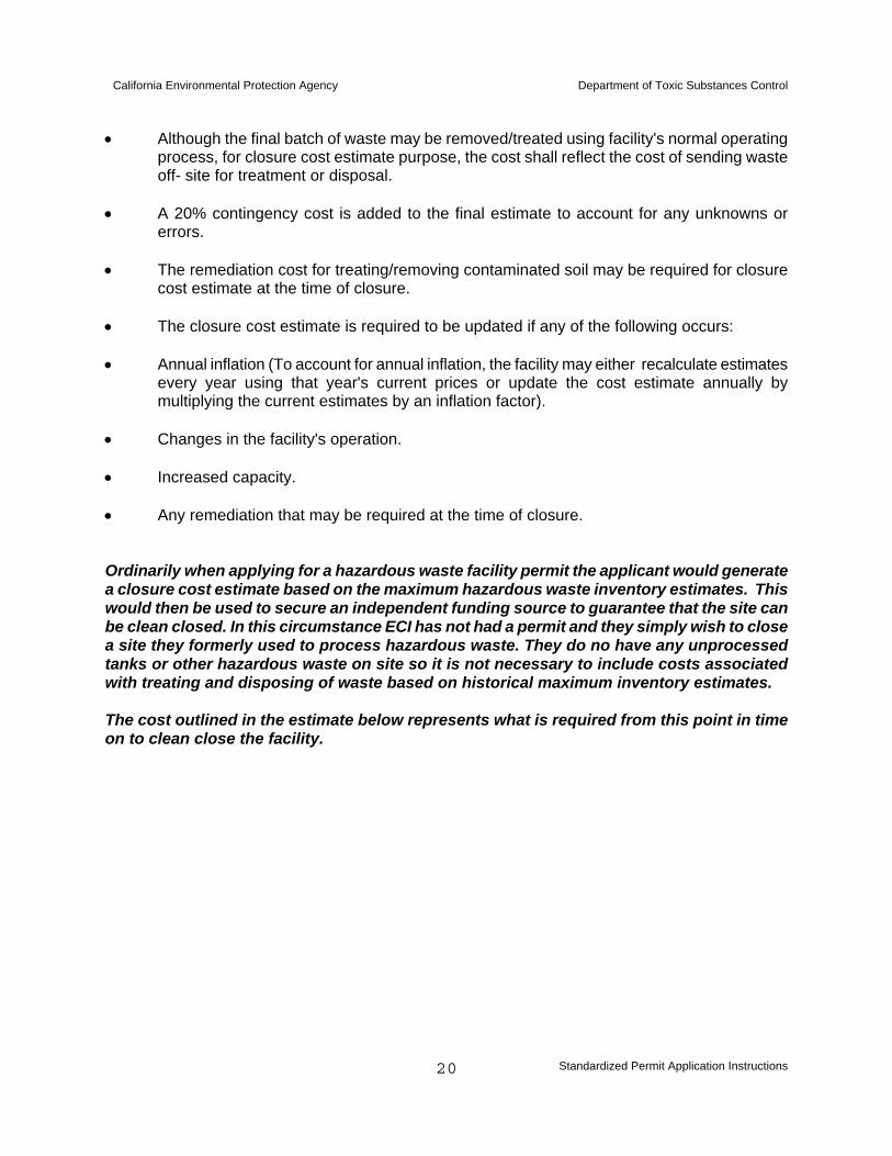
• Although the final batch of waste may be removed/treated using facility's normal operating
process, for closure cost estimate purpose, the cost shall reflect the cost of sending waste off- site for treatment or disposal.
• A 20% contingency cost is added to the final estimate to account for any unknowns or
errors. • The remediation cost for treating/removing contaminated soil may be required for closure
cost estimate at the time of closure. • The closure cost estimate is required to be updated if any of the following occurs: • Annual inflation (To account for annual inflation, the facility may either recalculate estimates
every year using that year's current prices or update the cost estimate annually by multiplying the current estimates by an inflation factor).
• Changes in the facility's operation. • Increased capacity. • Any remediation that may be required at the time of closure. Ordinarily when applying for a hazardous waste facility permit the applicant would generate a closure cost estimate based on the maximum hazardous waste inventory estimates. This would then be used to secure an independent funding source to guarantee that the site can be clean closed. In this circumstance ECI has not had a permit and they simply wish to close a site they formerly used to process hazardous waste. They do no have any unprocessed tanks or other hazardous waste on site so it is not necessary to include costs associated with treating and disposing of waste based on historical maximum inventory estimates. The cost outlined in the estimate below represents what is required from this point in time on to clean close the facility.

California Environmental Protection Agency Department of Toxic Substances Control
Standardized Permit Application Instructions
21
Table 2. Closure Cost Estimate
(Please insert page 1 of closure cost estimate here)

California Environmental Protection Agency Department of Toxic Substances Control
Standardized Permit Application Instructions
22
(Please insert page 2 of closure cost estimate here)
California Environmental Protection Agency Department of Toxic Substances Control
Standardized Permit Application Instructions
23
Table 3. Closure Cost Estimate Supporting Calculations
(Please insert closure cost estimate supporting calculations here)

California Environmental Protection Agency Department of Toxic Substances Control
Standardized Permit Application Instructions
24
K. CLOSURE SCHEDULE (66265.112(b)(6) & (7), 66265.113) The closure plan implementation must comply with the following closure schedule.
a) Wastes must be removed and structures/equipment decontaminated within 90 days of the date that the facility stopped receiving hazardous waste or the closure plan was approved whichever is later.
b) All closure activities must be completed within 180 days of the date that the facility
stopped receiving hazardous waste or the closure plan was approved whichever is later.
L. REMOVAL AND CLEAN-UP PROCEDURES a) If no contaminated soil is Identified: No action required
b) Contaminated Soil Identified: • ECI will submit an Excavation Proposal to DTSC with their soil sampling report (to
be submitted within 20 days of receipt of the laboratory results) • ECI will gain approvals from DTSC and other agencies (where required) • ECI will excavate up to 50 cubic yards (at a depth of up to two (2) feet) of
contaminated material with its own resources, utilizing skid-steer equipment or bulldozer or front-end loader.
• Material will be removed down to the depth indicated by Shaw Environmental soil analysis and follow-on analysis at designated intervals of excavation.
• Removed/excavated material will be loaded onto ECI owned end-dump trailers and hauled to TPS in Adelanto, CA for disposal.
Disposal Estimate for Excavated Dirt: Approx $23 per ton. 50 cubic yards equals approx 87.5 tons = $2,012.50
c) The Excavation Proposal is to include the following information:
• Details of the contaminant and its concentration • An outline of further tests ECI will conduct in order to fully define the extent of the
contamination (this is required to ensure that at the limits of the proposed excavation the soil is contaminant free).
• If VOC’s are found a copy of the SCAQMD mitigation plan. • Details of the recipient of the hazardous waste including a letter indicating they
authorized and willing to accept the hazardous waste. • Details of the proposed backfill (the results of the background tests will be used to
ensure that backfill material is of equal or better quality than the surrounding land). Also details of the compaction standards to be used.
• A project timeline.
d) Contaminated soils WILL NOT be treated on-site in TTU or similar systems.

California Environmental Protection Agency Department of Toxic Substances Control
Standardized Permit Application Instructions
25
e) Archaeological Findings: Consistent with State Health and Safety Code Section 7050.5, if human remains are encountered, the County Coroner will be notified immediately. Work shall stop until the County Coroner has made a determination of the origin and disposition of the remains pursuant to Public Resources Code Section 5097.98. If the remains are determined to be prehistoric, the Coroner will notify the Native American Heritage commission (NAHC) within 48 hours. The NAHC will determine and notify a Most Likely Descendant (MLD) within 24 hours. The MLD will make recommendation for the appropriate and dignified treatment of the remains (Public Resources Code, section 5097.98). With permission of the landowner or his/her authorized representative, the MLD may inspect the Site of the discovery. The MLD may recommend scientific removal and nondestructive analysis of human remains and items associated with Native American burials.
f) Landowner will inspect for acceptance and termination of lease agreement.
For further information on the soil removal plan refer to Section N. M. IMPLEMENTATION SCHEDULE a) Implementation Schedule pending permit approval date and DTSC Notice to Proceed.
b) All DTSC permit and instructional documents will be maintained at the closure site and at corporate headquarters in Torrance, CA
c) Upon Completion of clean-up and closure process, Shaw Environmental Engineers will certify a “Clean Closure” report within 60 days of work completion. See Section O.
d) Estimated closure completion date is May 1, 2007.

California Environmental Protection Agency Department of Toxic Substances Control
Standardized Permit Application Instructions
26
N. HEALTH & SAFETY PLAN (Please insert page 1 of health and safety plan here)

California Environmental Protection Agency Department of Toxic Substances Control
Standardized Permit Application Instructions
27
(Please insert page 2 of health and safety plan here)

California Environmental Protection Agency Department of Toxic Substances Control
Standardized Permit Application Instructions
28
(Please insert page 3 of health and safety plan here)

California Environmental Protection Agency Department of Toxic Substances Control
Standardized Permit Application Instructions
29
(Please insert page 4 of health and safety plan here)

California Environmental Protection Agency Department of Toxic Substances Control
Standardized Permit Application Instructions
30
(Please insert page 5 of health and safety plan here)
California Environmental Protection Agency Department of Toxic Substances Control
Standardized Permit Application Instructions
31
(Please insert page 6 of health and safety plan here)

California Environmental Protection Agency Department of Toxic Substances Control
Standardized Permit Application Instructions
32
(Please insert page 7 of health and safety plan here)

California Environmental Protection Agency Department of Toxic Substances Control
Standardized Permit Application Instructions
33
(Please insert page 8 of health and safety plan here)

California Environmental Protection Agency Department of Toxic Substances Control
Standardized Permit Application Instructions
34
O. SITE SECURITY 1. The entire perimeter of this property is fenced and co-located with other industries adjacent
to the fence. 2. There is a chain-link gate at the entrance to the property. This will remain closed and
locked when the site is unmanned. During the closure process and work is underway, security will be provided by ECI supervisory personnel.
3. A log of entry will be maintained in accordance with current ECI Safety Policy – HS903,
dated March 2006. Detailed information is contained in Attachment 10. 4. A nearby point of contact for security issues is the ECI Montclair facility a few miles west of
the closure site. The contact phone number is: 909-625-6645 or 1-800-236-7324. 24 hour contact will be the Torrance Dispatcher at 310-787-2807 or 1-800-321-5479.
P. CLOSURE CERTIFICATION Note: This section will be required to be submitted after the completion of closure activities. After all closure activities have been completed, a closure certification must be submitted. The certification must be submitted to DTSC by registered mail within 60 days of completion of closure activity. 1. The Closure certification shall contain the following:
a) Certification by independent Professional Engineer - This document must be signed by both the owner or operator and independent professional engineer registered in California.
b) Supervisory Personnel Description - Identify the person(s) or companies who were
responsible for supervision of closure activities at the site, including transportation of waste and sample collection.
c) Summary of Closure Activities - Briefly describe the main activities performed for
each closure activity.
d) Field Engineer Observation Report.
e) Sampling Data and Analysis - All sampling information such as sampling locations, soil boring log, chain of custody, analytical results should be included.
f) Discussion of Analytical Results.
g) Manifests - Copies of manifests showing the disposition of the waste inventory.

California Environmental Protection Agency Department of Toxic Substances Control
Standardized Permit Application Instructions
35
h) Modifications and Amendments to Closure Plan – Specifically the report will indicate what if any material was excavated and provide details of locations and depths.
i) Photographs.
2. The facility also must keep and maintain the following documents at the facility until
the closure certification approval:
a) Approved Closure Plan.
b) Copies of the independent Professional Engineer's field observation reports.
c) Laboratory results of samples analyzed. d) Quality assurance/quality control demonstrations.
e) Manifests.
f) Miscellaneous documents.
g) Closure certification report.