haze-gloss - byk additives & · pdf fileperiods under adverse conditions ......
TRANSCRIPT
Additives & InstrumentsA member of
Manual Betriebsanleitung
Modo d’emploi
Istruzioni d’uso
Measure what you see.
haze-gloss
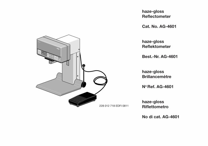
haze-glossReflectometer
Cat. No. AG-4601
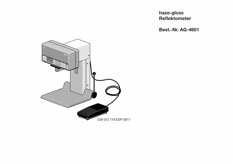
haze-glossReflektometer
Best.-Nr. AG-4601
haze-glossBrillancemètre
No Ref. AG-4601
haze-glossRiflettometro
No di cat. AG-4601
Gardner
haze-gloss
GardenerVersion: 2.6Copyright 1990
Gesamtansicht
228 012 718 EDFI 0811


Gardner
haze-gloss
GardenerVersion: 2.6Copyright 1990
Gesamtansicht
haze-glossReflectometer
Cat.No. AG-4601
Table of Contents
1. SafetyInformation 2.SystemDescription 3.Start-Up 4.Operation 5.Calibration 6.SettingtheInstrumentParameters SETUPMenu 7.PracticalMeasuringHints 8.MeasurementSeriesandStatistic 9.InternationalSpecifications10.InterfaceDescription11.TechnicalData12.SourcesofErrors13.OrderingGuide
TechnicalDataareSubjecttoAlterations.
Gardner
haze-gloss
Gardner
BYK
GardenerVersion: 2.6Copyright 1990
haze
20°
60°
85°
20° + 60°auto-range
60° + 85°
sample/statistic results
delete
set up
operate
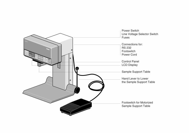
Power SwitchLine Voltage Selector SwitchFuses
Connections for:RS 232FootswitchPower Cord
Control PanelLCD Display
Sample Support Table
Hand Lever to Lowerthe Sample Support Table
Footswitch for MotorizedSample Support Table
Gardner
haze-gloss
Gardner
BYK
GardenerVersion: 2.6Copyright 1990
haze
20°
60°
85°
20° + 60°auto-range
60° + 85°
sample/statistic results
delete
set up
operate
Power SwitchLine Voltage Selector SwitchFuses
Connections for:RS 232FootswitchPower Cord
Control PanelLCD Display
Sample Support Table
Hand Lever to Lowerthe Sample Support Table
Footswitch for MotorizedSample Support Table
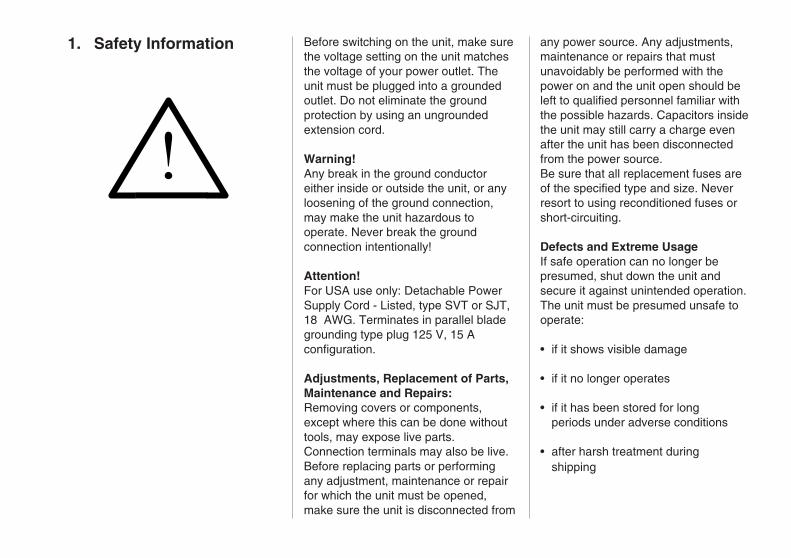
!
1. Safety Information any power source. Any adjustments,maintenance or repairs that mustunavoidably be performed with thepower on and the unit open should beleft to qualified personnel familiar withthe possible hazards. Capacitors insidethe unit may still carry a charge evenafter the unit has been disconnectedfrom the power source.Be sure that all replacement fuses areof the specified type and size. Neverresort to using reconditioned fuses orshort-circuiting.
Defects and Extreme UsageIf safe operation can no longer bepresumed, shut down the unit andsecure it against unintended operation.The unit must be presumed unsafe tooperate:
• if it shows visible damage
• if it no longer operates
• if it has been stored for longperiods under adverse conditions
• after harsh treatment duringshipping
Before switching on the unit, make surethe voltage setting on the unit matchesthe voltage of your power outlet. Theunit must be plugged into a groundedoutlet. Do not eliminate the groundprotection by using an ungroundedextension cord.
Warning!Any break in the ground conductoreither inside or outside the unit, or anyloosening of the ground connection,may make the unit hazardous tooperate. Never break the groundconnection intentionally!
Attention!For USA use only: Detachable PowerSupply Cord - Listed, type SVT or SJT,18 AWG. Terminates in parallel bladegrounding type plug 125 V, 15 Aconfiguration.
Adjustments, Replacement of Parts,Maintenance and Repairs:Removing covers or components,except where this can be done withouttools, may expose live parts.Connection terminals may also be live.Before replacing parts or performingany adjustment, maintenance or repairfor which the unit must be opened,make sure the unit is disconnected from

The haze-gloss reflectometer is a stationary instrument designed to measure specular gloss and reflection haze on paint coatings, plastics, binders, pigments, and metal surfaces (mirror reflection).
The sample surface is illuminated at a defined angle and the reflected light is measured photoelectrically.Selection of the appropriate angle of illumination (geometry) is dependent on the specific gloss level of the sample surface: matt, medium, or high gloss. (For the application of these measuring ranges, see Chapter 6, Practical Measuring Hints.) Advanced electronic engineering in the development and production of haze-gloss provides a performance level, ease of operation and high accuracy at a level not previously achieved.
• Three geometries: 20°, 60° and 85° Mirror reflection on metal surfaces, Reflection haze
• Sample pressing device allows for a rapid change of samples, sample support table optionally
2. System Description
positioning
• Easy-to-readcontrolpaneland microprocessorcontrolledoperation
• Highaccuracyandlong-termstability duetoreferencebeamprinciple
• Nowarm-uptime,immediateopera-tion,long-termcalibration(≥every twomonths)
• Internalstatisticmodeandstorage
• Interfacefordatatransferand controlviaPC
• Displaycanbeselectedtobe English,German,French,Spanish,or Italian
Thehaze-glossmeasuringunitconformswiththestandardsISO2813,ASTMD523andDIN67530.Inaddition,ithasbeentestedbythe"BundesanstaltfürMaterialprüfung(BAM)"andwasfoundtofulfiltherequirementsassetbytheDIN67530standard(January1982).
motorized and controlled using a footswitch
• Illuminated target for accurate sample positioning
• Easy-to-read control panel and microprocessor controlled operation
• High accuracy and long-term stability due to reference beam principle
• No warm-up time, immediate opera- tion, long-term calibration (≥ every two months)
• Internal statistic mode and storage
• Interface for data transfer and control via PC
• Display can be selected to be English, German, French, Spanish, or Italian
The haze-gloss measuring unit con-forms with the standards ISO 2813, ASTM D 523 and DIN 67 530.
Thehaze-glossreflectometerisastatio-naryinstrumentdesignedtomeasurespecularglossandreflectionhazeonpaintcoatings,plastics,binders,pigments,andmetalsurfaces(mirrorreflection).
Thesamplesurfaceisilluminatedatadefinedangleandthereflectedlightismeasuredphotoelectrically.Selectionoftheappropriateangleofillu-mination(geometry)isdependentonthespecificglosslevelofthesamplesurface:matt,medium,orhighgloss.(Fortheapplicationofthesemeasuringranges,seeChapter6,PracticalMeasuringHints.)Advancedelectronicengineeringinthedevelopmentandproductionofhaze-glossprovidesaperformancelevel,easeofoperationandhighaccuracyatalevelnotpreviouslyachieved.
•Threegeometries:20°,60°and85°Mirrorreflectionon metalsurfaces, Reflectionhaze
•Samplepressingdeviceallowsforarapidchangeofsamples, samplesupporttableoptionally motorizedandcontrolledusinga footswitch
• Illuminatedtargetforaccuratesample
2.SystemDescription
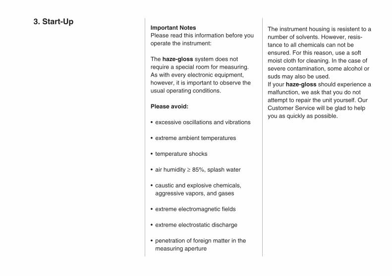
The instrument housing is resistent to anumber of solvents. However, resis-tance to all chemicals can not beensured. For this reason, use a softmoist cloth for cleaning. In the case ofsevere contamination, some alcohol orsuds may also be used.If your haze-gloss should experience amalfunction, we ask that you do notattempt to repair the unit yourself. OurCustomer Service will be glad to helpyou as quickly as possible.
Important NotesPlease read this information before youoperate the instrument:
The haze-gloss system does notrequire a special room for measuring.As with every electronic equipment,however, it is important to observe theusual operating conditions.
Please avoid:
• excessive oscillations and vibrations
• extreme ambient temperatures
• temperature shocks
• air humidity ≥ 85%, splash water
• caustic and explosive chemicals,aggressive vapors, and gases
• extreme electromagnetic fields
• extreme electrostatic discharge
• penetration of foreign matter in themeasuring aperture
3. Start-Up
3. Start-Up Important NotesPlease read this information before youoperate the instrument:
The haze-gloss system does notrequire a special room for measuring.As with every electronic equipment,however, it is important to observe theusual operating conditions.
Please avoid:
• excessive oscillations and vibrations
• extreme ambient temperatures
• temperature shocks
• air humidity ≥ 85%, splash water
• caustic and explosive chemicals,aggressive vapors, and gases
• extreme electromagnetic fields
• extreme electrostatic discharge
• penetration of foreign matter in themeasuring aperture
The instrument housing is resistent to anumber of solvents. However, resis-tance to all chemicals can not beensured. For this reason, use a softmoist cloth for cleaning. In the case ofsevere contamination, some alcohol orsuds may also be used.If your haze-gloss should experience amalfunction, we ask that you do notattempt to repair the unit yourself. OurCustomer Service will be glad to helpyou as quickly as possible.

Gardner
haze-gloss
Gardner
BYK
GardenerVersion: 2.6Copyright 1990
Footswitch
RS 232 Interface
Voltage SelectorFuses
Jack for Power CordPower Switch
TYP
CAT.-NR.
F-NR.
4601
9017571
110/220 V 50/60 HZ250
VA
BYK-GARDENER GMBH
LAUSITZER STR. 8
8192 GERETSRIED 2
TELEFON (08171) 493-0
TELEX 5 27 851
TELEFAX (0871) 493-40
USE O
NLY W
ITH 250 V
FUSES / EM
PLOYER
UN
IQU
EMEN
T AVEC
DES FU
IBLES W
ITH 250 V
110-120 V
220-
240
V
Installation
Always disconnect the instrument fromthe mains supply before you plug-in orunplug the various connectors!
Unpack the instrument and check forany possibility of shipping damage(visual inspection). Before initialoperation, check if the delivery iscomplete (for the components seeChapter 12, Ordering Guide ).
Install the unit at its place of destination.Check the position of the voltageselector switch on the back panel and, ifnecessary, set the switch to your powerrequirements as follows: Remove theplastic cover next to the mains cordjack. Then plug-in the plastic cover sothat the triangular marking on the powerswitch housing and the required voltagerange indication coincide.
With the unit being still disconnected,plug the power cord into the shockproofsocket. In the case of motorized units:connect the footswitch.
If required, plug the PC connectioncable into the RS 232 jack.
Gardner
haze-gloss
Gardner
BYK
GardenerVersion: 2.6Copyright 1990
Footswitch
RS 232 Interface
Voltage SelectorFuses
Jack for Power CordPower Switch
TYP
CAT.-NR.
F-NR.
4601
9017571
110/220 V 50/60 HZ250
VA
BYK-GARDENER GMBH
LAUSITZER STR. 8
8192 GERETSRIED 2
TELEFON (08171) 493-0
TELEX 5 27 851
TELEFAX (0871) 493-40
USE O
NLY W
ITH 250 V
FUSES / EM
PLOYER
UN
IQU
EMEN
T AVEC
DES FU
IBLES W
ITH 250 V
110-120 V
220-
240
VInstallation
Always disconnect the instrument fromthe mains supply before you plug-in orunplug the various connectors!
Unpack the instrument and check forany possibility of shipping damage(visual inspection). Before initialoperation, check if the delivery iscomplete (for the components seeChapter 12, Ordering Guide ).
Install the unit at its place of destination.Check the position of the voltageselector switch on the back panel and, ifnecessary, set the switch to your powerrequirements as follows: Remove theplastic cover next to the mains cordjack. Then plug-in the plastic cover sothat the triangular marking on the powerswitch housing and the required voltagerange indication coincide.
With the unit being still disconnected,plug the power cord into the shockproofsocket. In the case of motorized units:connect the footswitch.
If required, plug the PC connectioncable into the RS 232 jack.

Version: 2.8Copyright 1990
Gardner
Switch on the unit using the powerswitch on the rear panel.
Logotype and copyright messageappear in the display.
The haze-gloss performs a self-diagnostic test.
NoteMotorized units also test the downwardmovement, provided that no sample isinserted.
The status of the set parametersappears in the display.
SELF-DIAGNOSTIC
LampLampLampLowerLower
20°:60°:85°:4 cm:7 cm:
okokokokok
STATUS
Haze Compens.:Lower:Autom. Meas.:Target:
ok4 cmonon

20° 36.760° 73.2
REFLECTOMETER
20° :60° :85° :Haze:20° Cust. spec:60° Cust. spec:85° Cust. spec:
99.293.390.1457 2000 1000 300
ASTM
The stored calibration values appear onthe display. Display of customizedcalibration values requires priordefinition (see Chapter 5).
The number of stored readings appearson the display.
After completion of self-diagnostic testand display of status, the instrumentimmediately goes to the last modeactivated before the unit wasdisconnected and is now ready foroperation.
Before you start measuring, thehaze-gloss has to be calibrated (seeChapter 5).
STATUS
Stored Values:20° :60° :85° :Haze:20°& 60°:60°& 85°:
n= 520n= 82n= 0n= 571n= 101n= 0
STATUS
Stored Values:20° :60° :85° :Haze:20°& 60°:60°& 85°:
n= 520n= 82n= 0n= 571n= 101n= 0

haze 20° 60° 85°
20° + 60° auto-range 60° + 85°
Select the desired geometry or theauto-range function (see Chapter 6,Practical Measuring Hints).
Lower the sample support tableusing the hand lever, or the footswitchin the case of a motorized table.
Insert sample, test surface facing up.
Check the sample for possible surfacedefects (e.g. scratches, fingerprints).The illuminated target marks thesample port position (see SET UPMenu: Target)
Release hand lever or footswitchrespectively. Now the support tablemoves the sample towards thesample port.
The measurement is started automati-cally but can also be started manuallyby pressing the operate key.(see SET UP Menu: Measure autom.)
The measured values and the corre-sponding geometry/measuringmode appear in the display.
4. Operation
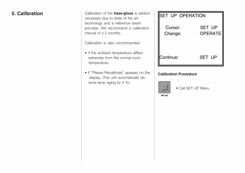
• Call SET UP Menu
SET UP OPERATION Cursor: SET UP Change: OPERATE
Continue: SET UP
5. Calibration
• Call SET UP Menu
SET UP OPERATION Cursor: SET UP Change: OPERATE
Continue: SET UP
5. Calibration Calibration of the haze-gloss is seldomnecessary due to state of the arttechnology and a reference beamprinciple. We recommend a calibrationinterval of ≥ 2 months.
Calibration is also recommended
• if the ambient temperature differs extremely from the normal room temperature.
• if "Please Recalibrate" appears on the display. (The unit automatically de- tects lamp aging by 4 %)
set up
Calibration Procedure
Calibration Procedure
set up
Calibration of the haze-gloss is seldomnecessary due to state of the arttechnology and a reference beamprinciple. We recommend a calibrationinterval of ≥ 2 months.
Calibration is also recommended
• if the ambient temperature differs extremely from the normal room temperature.
• if "Please Recalibrate" appears on the display. (The unit automatically de- tects lamp aging by 4 %)
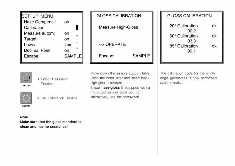
GLOSS CALIBRATION Measure High-Gloss
--> OPERATE
Escape:
SAMPLE
GLOSS CALIBRATION 20° Calibration ok
90.2 60° Calibration ok
93.3 85° Calibration ok
99.1
set up
operate
Move down the sample support tableusing the hand lever and insert blackhigh-gloss standard.If your haze-gloss is equipped with amotorized sample table you canalternatively use the footswitch.
The calibration cycle for the singleangle geometries is now performedautomatically.
SET UP MENU Haze Compens.: Calibration Measure autom: Target: Lower: Decimal Point: Escape:
on
onon4cmonSAMPLE
GLOSS CALIBRATION Measure High-Gloss
--> OPERATE
Escape:
SAMPLE
• Select Calibration Routine
• Call Calibration Routine
NoteMake sure that the glass standard isclean and has no scratches!
• Select Calibration Routine
• Call Calibration Routine
NoteMake sure that the glass standard isclean and has no scratches!

Calibration is completed.
• Go into the measuring mode by pressing the sample/statistic key.
Important!Only use standards supplied with theinstrument. These have been calibratedagainst officially tested standards andcorrespond to ASTM D 523 orDIN 67 530. Should a standard bedamaged or lost, the haze-gloss has tobe recalibrated with new standards byour service engineers as the values ofyour original standards are memo-rizedin the instrument.
Haze Calibration
Insert white haze tile.The haze standard must be clean andfree of scratches.
• Press the operate key
NoteThe value indicated on the hazestandard has been reduced by theluminance factor (see Chapter 6, HazeCompensation).
Customer-specified Calibration
For mirror reflection measurements youcan calibrate the instrument using yourcompany's own standards and definespecific reflectometer values. All futuremeasurements will then be related tothese values.
• Call the SET UP Menu and select "Change Cal. Value" (2nd page of menu)
• press the operate key to define "Custom Cal."
• Select desired geometry
HAZE CALIBRATION Haze cal. ok457
HAZE CALIBRATION Measure Haze Tile --> OPERATE
Escape:
SAMPLE
CUSTOM SPEC. CALIB.MIRROR MODE 20°: Val.: not defined 60°: Val.: 1000 85°: Val.: not defined
Escape:
SAMPLE
operate
sample/statistic
set up
operate

• Set reflectometer value:
• Press the set up key to change the number above the arrow, cycling from 0 - 9.
• Confirm the selected number using the operate key. The arrow jumps to the next number.
• Measure mirror reflection standard.
• haze-gloss calibration is performed against your
own standard.
CUSTOM SPEC. CALIB. Calib. Value 20° * * * 1 2 3 0 * * * Change Value: Confirm:Escape:
SETUPOPERATE SAMPLE
CUSTOM SPEC. CALIB.
Measure Custom Tile 20° : 1000 --> OPERATE
Escape:
SAMPLE
set up
operate
operate
Note
If you define very high standard values,limit errors might occur during themeasurement as the numerical range islimited to 500 gloss units. In this case,4 stars will be displayed instead of thereflectometer value.
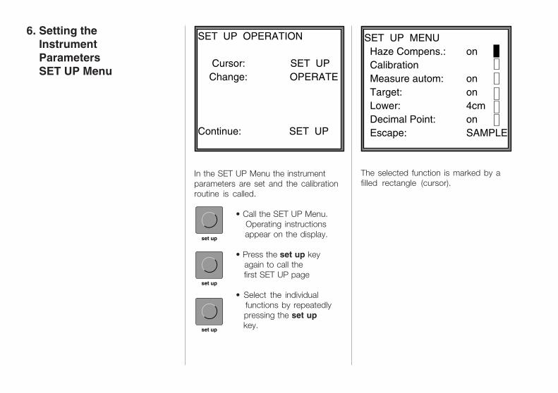
In the SET UP Menu the instrumentparameters are set and the calibrationroutine is called.
• Call the SET UP Menu. Operating instructions appear on the display.
• Press the set up key again to call the first SET UP page
• Select the individual functions by repeatedly pressing the set up key.
SET UP OPERATION Cursor: SET UP Change: OPERATE
Continue: SET UP
set up
set up
set up
SET UP MENU Haze Compens.: Calibration Measure autom: Target: Lower: Decimal Point: Escape:
on
onon4cmonSAMPLE
The selected function is marked by afilled rectangle (cursor).
6. Setting the Instrument Parameters SET UP Menu
SET UP OPERATION Cursor: SET UP Change: OPERATE
Continue: SET UP
SET UP MENU Haze Compens.: Calibration Measure autom: Target: Lower: Decimal Point: Escape:
on
onon4cmonSAMPLE
6. Setting the Instrument Parameters SET UP Menu
In the SET UP Menu the instrumentparameters are set and the calibrationroutine is called.
• Call the SET UP Menu. Operating instructions appear on the display.
• Press the set up key again to call the first SET UP page
• Select the individual functions by repeatedly pressing the set up key.
set up
set up
set up
The selected function is marked by afilled rectangle (cursor).

BYK
GardenerVersion: 2.6Copyright 1990
haze
20°
60°
85°
20° + 60°auto-range
60° + 85°
sample/statistic results
delete
set up
operate
Description of the IndividualFunctions:
Haze Compensation(Compensation of the luminance factor)The light scattered diffusely by thesample is detected by a specialaperture and can be subtracted fromthe haze values. The brighter thesample, the more important becomesthis haze effect. (e.g. with white enamel)In the mode "Haze Compens.: off" hazevalues are displayed with the indication"nc." = not compensated.Pigmented samples such as paints orplastics should always be measuredwith "Compensation on" since thesample luminosity affects the hazevalue.
CalibrationCall the calibration routine(see Chapter 5)
Automatic MeasurementWhen raising the sample support tablea measurement is taken automatically,thus minimizing keystrokes.
TargetA target is automatically activated withthe downward movement of the samplesupport table.
LowerIn the case of a motorized samplesupport table the downward movementcan be set to 4 or 7 cm.
Decimal PointThe decimal point can be suppressedusing the "decimal point off" function.Calculations in the statistic mode arealways performed with the exact value.
• Call or change the selected function.
• Leave the SET UP Menu
SET UP MENU Country D,US,F,I,E Mirror Mode: Change Cal. Value: Custom. Cal.: Escape:
on
onSAMPLE
sample/statistic
operate
BYK
GardenerVersion: 2.6Copyright 1990
haze
20°
60°
85°
20° + 60°auto-range
60° + 85°
sample/statistic results
delete
set up
operate
SET UP MENU Country D,US,F,I,E Mirror Mode: Change Cal. Value: Custom. Cal.: Escape:
on
onSAMPLE
sample/statistic
operate
Description of the IndividualFunctions:
Haze Compensation(Compensation of the luminance factor)The light scattered diffusely by thesample is detected by a specialaperture and can be subtracted fromthe haze values. The brighter thesample, the more important becomesthis haze effect. (e.g. with white enamel)In the mode "Haze Compens.: off" hazevalues are displayed with the indication"nc." = not compensated.Pigmented samples such as paints orplastics should always be measuredwith "Compensation on" since thesample luminosity affects the hazevalue.
CalibrationCall the calibration routine(see Chapter 5)
Automatic MeasurementWhen raising the sample support tablea measurement is taken automatically,thus minimizing keystrokes.
TargetA target is automatically activated withthe downward movement of the samplesupport table.
LowerIn the case of a motorized samplesupport table the downward movementcan be set to 4 or 7 cm.
Decimal PointThe decimal point can be suppressedusing the "decimal point off" function.Calculations in the statistic mode arealways performed with the exact value.
• Call or change the selected function.
• Leave the SET UP Menu

7. Practical Measuring Hints
Gloss Measuring
In accordance with DIN 67 530 thereflectometer value is related to a blackglass standard with a refraction indexof 1.567 (reflectometer value 100).Reflectometers are differentiated by theangle of illumination of the light source.In accordance with DIN 67 530 andASTM D 523 the angles are set at 20°,60° and 85°; each setting correspondsto a particular application:
• Semi-gloss surfaces are measured at an angle of 60°. Measurements should range between 10 and 70 gloss units.
Language US, D, F, I, EDisplay can be selected to be English,German, French, Italian or Spanish.
Mirror Modeoff: If a gloss value exceeds
approx.190 the haze-glossautomatically goes to a lowerchannel and takes a new mea-surement.
on: If only high-gloss samples(e.g. metals) have to be mea-sured, you will save time with themirror mode.
Change Calibration ValueIn this mode you can calibrate againstyour own mirror gloss standard with adefined reflectometer value. (SeeChapter 5, Calibration)
Customer-specifiedMeasurements(Only displayed if defined)Calculation of reflectometer valuesrelated to a customer-specifiedmirror standard.
20° 36.760° 73.2
20° 36.760° 73.2
7. Practical Measuring Hints
Gloss Measuring
In accordance with DIN 67 530 thereflectometer value is related to a blackglass standard with a refraction indexof 1.567 (reflectometer value 100).Reflectometers are differentiated by theangle of illumination of the light source.In accordance with DIN 67 530 andASTM D 523 the angles are set at 20°,60° and 85°; each setting correspondsto a particular application:
• Semi-gloss surfaces are measured at an angle of 60°. Measurements should range between 10 and 70 gloss units.
Language US, D, F, I, EDisplay can be selected to be English,German, French, Italian or Spanish.
Mirror Modeoff: If a gloss value exceeds
approx.190 the haze-glossautomatically goes to a lowerchannel and takes a new mea-surement.
on: If only high-gloss samples(e.g. metals) have to be mea-sured, you will save time with themirror mode.
Change Calibration ValueIn this mode you can calibrate againstyour own mirror gloss standard with adefined reflectometer value. (SeeChapter 5, Calibration)
Customer-specifiedMeasurements(Only displayed if defined)Calculation of reflectometer valuesrelated to a customer-specifiedmirror standard.

AUTO-RANGE60° 20.785° 47.2
• If highly reflective surfaces are measured using the 60° geometry and the measured value exceeds 70 units, the measurement should be repeated using the 20° geometry.
• Matt surfaces showing measured values of less than 10 units (using the 60° geometry), should be measured using the 85° geometry.
In order to obtain a better differentiationof the measured values, we recom-mend the 85° geometry in all cases inwhich the value measured at 60° isbelow 30 units. Application recommen-dations differ in the various standards.While the ASTM D 523 standard setsthe upper limit for changing from 60° to85° geometry at the value of 10 glossuntis, ISO 2813 sets this limit at 30units. These limits should be regardedas recommendations.
Mirror Reflection Measurements
The haze-gloss offers an extendedmeasuring range, which allows for themeasurement of samples with greatreflecting power (polished metal
surfaces, mirrors). In this mode thegloss values range up to:
2000 gloss units at 20°1000 gloss untis at 60° 160 gloss units at 85°
(calibration performed at the manufac-turer).
As mirror gloss measurements areoften related to customers' standards,haze-gloss offers the possibility tocalibrate against customer-specifiedstandards (see Chapter 5, Calibration).
Note
• In the auto-range mode the 60/85° dual angle geometry is used for reflectometer values below 30; the 60° single angle geometry is used for reflectometer values between 30 and 70, and the 20°/60° dual angle geo- metry is used for reflectometer values exceeding 70. (Reflectometer values always relate to 60°)
• It is not useful to take measurements on samples showing contaminations, scratches or other damages, unless you want to evaluate the degree of such defects by means of gloss measurement.
• Best results can only be obtained from plane surfaces.
• Since gloss properties are usually not constant over the complete sample surface, the reflectometer value should be determined on several different locations of the sample and the readings should be averaged.
• If a sample surface is structured, i.e. the gloss porperties are dependent on the measuring direction, it is recommended to report the structure characteristics and the angle of incidence or to calculate the mean value from readings taken in varying directions.
• Samples that have to be measured several times during a test (e.g. weathering samples) should be marked correspondingly in order to make sure that comparison measurements or check tests will be performed on the same location.
Haze Measurement provides:
• better differentiation of optical properties for high gloss surfaces
• an indirect method to evaluate and characterize paint and raw material properties, such as
- degree of dispersion- flocculation behavior- wetting properties- scratch resistance- weathering tests- optimization of paint formulae
• an indirect method to evaluate the manufacturing process of the surface.
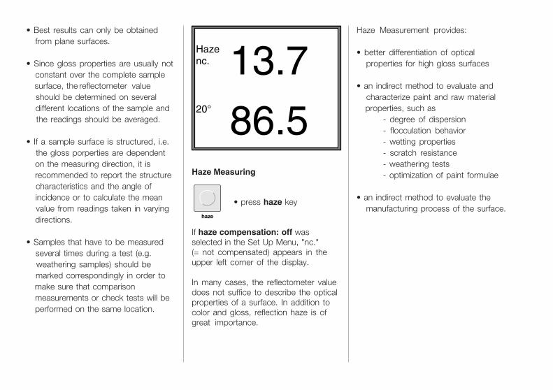
Haze Measuring
• press haze key
If haze compensation: off wasselected in the Set Up Menu, "nc."(= not compensated) appears in theupper left corner of the display.
In many cases, the reflectometer valuedoes not suffice to describe the opticalproperties of a surface. In addition tocolor and gloss, reflection haze is ofgreat importance.
Hazenc. 13.720° 86.5
haze
• Best results can only be obtained from plane surfaces.
• Since gloss properties are usually not constant over the complete sample surface, the reflectometer value should be determined on several different locations of the sample and the readings should be averaged.
• If a sample surface is structured, i.e. the gloss porperties are dependent on the measuring direction, it is recommended to report the structure characteristics and the angle of incidence or to calculate the mean value from readings taken in varying directions.
• Samples that have to be measured several times during a test (e.g. weathering samples) should be marked correspondingly in order to make sure that comparison measurements or check tests will be performed on the same location.
Haze Measurement provides:
• better differentiation of optical properties for high gloss surfaces
• an indirect method to evaluate and characterize paint and raw material properties, such as
- degree of dispersion- flocculation behavior- wetting properties- scratch resistance- weathering tests- optimization of paint formulae
• an indirect method to evaluate the manufacturing process of the surface.
Haze Measuring
• press haze key
If haze compensation: off wasselected in the Set Up Menu, "nc."(= not compensated) appears in theupper left corner of the display.
In many cases, the reflectometer valuedoes not suffice to describe the opticalproperties of a surface. In addition tocolor and gloss, reflection haze is ofgreat importance.
Hazenc. 13.720° 86.5
haze

The Equation
The equation for reflection haze is:H = K x lg (linear haze value/20 + 1).
In order to achieve a logarithmical hazevalue of 1000 at a linear value of 100haze units, the constant k = 1285.1 isused.
The Equation
The equation for reflection haze is:H = K x lg (linear haze value/20 + 1).
In order to achieve a logarithmical hazevalue of 1000 at a linear value of 100haze units, the constant k = 1285.1 isused.
For the measurement of reflection haze,2 additional apertures c (width = 1.8°)are positioned on either side of the 20°specular gloss aperture. This allows forthe measurement of the diffuselyscattered light adjacent to the 20°specular angle.
Note
The reflection haze value is displayedlogarithmically
• in order to correspond as close as possible with the visual perception of reflection haze by the human eye.
• in order to achieve a higher sensitivity in the case of low haze values. (The lower the haze value, the better the surface quality.)
������
��
����
��haze
20 020 0
60 0
60 0
85 0
85 0
a
b
c
a
������
��
����
��haze
20 020 0
60 0
60 0
85 0
85 0
a
b
c
a
20°36.760°73.4
n=123m=36.5 s= 1.3
m=73.3 s= 0.9
sample/statistic
s= 1 /n-1 ∑(xi-x)2n
i=1
-
20° m= 36.5 min= 32.8 max= 40.6
60° m= 73.3 min= 70.8 max= 75.7
n= 123 s= 1.3Vr= 3.6
s= 0.9Vr= 1.2
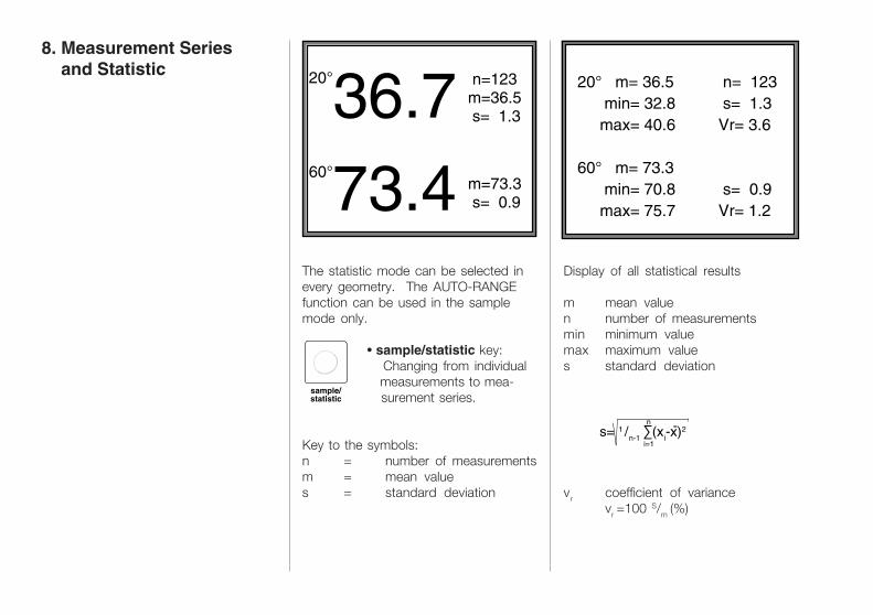
Display of all statistical results
m mean valuen number of measurementsmin minimum valuemax maximum values standard deviation
vr coefficient of variancevr =100 S/m (%)
The statistic mode can be selected inevery geometry. The AUTO-RANGEfunction can be used in the samplemode only.
• sample/statistic key: Changing from individual measurements to mea- surement series.
Key to the symbols:n = number of measurementsm = mean values = standard deviation
20°36.760°73.4
n=123m=36.5 s= 1.3
m=73.3 s= 0.9
sample/statistic
20° m= 36.5 min= 32.8 max= 40.6
60° m= 73.3 min= 70.8 max= 75.7
n= 123 s= 1.3Vr= 3.6
s= 0.9Vr= 1.2
Display of all statistical results
m mean valuen number of measurementsmin minimum valuemax maximum values standard deviation
vr coefficient of variancevr =100 S/m (%)
The statistic mode can be selected inevery geometry. The AUTO-RANGEfunction can be used in the samplemode only.
• sample/statistic key: Changing from individual measurements to mea- surement series.
Key to the symbols:n = number of measurementsm = mean values = standard deviation
8. Measurement Series and Statistic
8. Measurement Series and Statistic
s= 1 /n-1 ∑(xi-x)2n
i=1
-

• delete key deletes last reading.
The counting variable n is reducedby 1. The last reading can only bedeleted if no other function has beencalled after the last measurement.
• results key deletes the complete measurement series of the set geometry.
DELETE Delete last value -->DELETE
Delete statistics -->RESULTS
Escape:
SAMPLE
Note
Measurement values in the statisticmode are stored and are protectedwhen changing the geometry or usingthe sample mode.haze-gloss can store a series of up to600 measurements per geometry.These data can be transferred to a PCvia RS 232 interface.If the geometry is changed in thestatistic mode, the values of the lastmeasured series are displayed and theseries can be continued if required.During a running measuring series inthe statistic mode the calibration mustnot be changed (compensation, mirrorgloss, customer-specified) since thiswould falsify the statistical results.
delete
results
delete
results
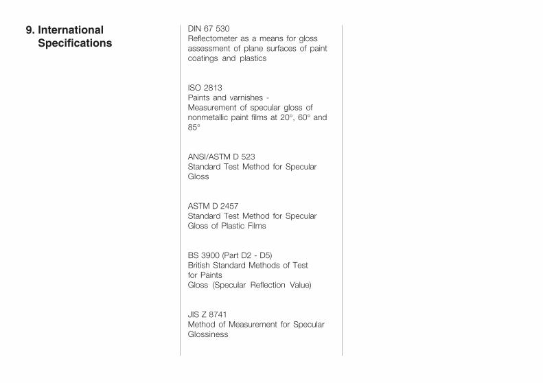
DIN 67 530Reflectometer as a means for glossassessment of plane surfaces of paintcoatings and plastics
ISO 2813Paints and varnishes -Measurement of specular gloss ofnonmetallic paint films at 20°, 60° and85°
ANSI/ASTM D 523Standard Test Method for SpecularGloss
ASTM D 2457Standard Test Method for SpecularGloss of Plastic Films
BS 3900 (Part D2 - D5)British Standard Methods of Testfor PaintsGloss (Specular Reflection Value)
JIS Z 8741Method of Measurement for SpecularGlossiness
9. International Specifications
9. International Specifications
DIN 67 530Reflectometer as a means for glossassessment of plane surfaces of paintcoatings and plastics
ISO 2813Paints and varnishes -Measurement of specular gloss ofnonmetallic paint films at 20°, 60° and85°
ANSI/ASTM D 523Standard Test Method for SpecularGloss
ASTM D 2457Standard Test Method for SpecularGloss of Plastic Films
BS 3900 (Part D2 - D5)British Standard Methods of Testfor PaintsGloss (Specular Reflection Value)
JIS Z 8741Method of Measurement for SpecularGlossiness

10. Interface Description
10. Interface Description
The haze-gloss is equipped with aserial interface (RS 232 C), whichallows for data handling and control ofthe unit with a PC.A 9-pin SUB-D connector is mountedon the measuring unit for transferpurposes.
haze-gloss PC3 TxD -------- RxD 32 RxD -------- TxD 27 RTS -------- CTS 58 CTS -------- RTS 45 ------ GND ------ 7
Transfer Rate and FormatThe serial asynchronous transfer ofdata is specified in the measuring unitand is performed according to thefollowing format:
2400 baud, 8 data bits, no parity,1 stop bit
Control Commands'O' (ASCII) starts the on-line operation(ONLINE appears on the display)- the haze-gloss keyboard is blocked- automatic measurement is started using the operating switch
SET UP Status of haze-gloss istransferred to the computer:(1 byte each INTEGER)
- Current Mode:0 = sample mode1 = statistic mode
- Selected Geometry:0 = haze1 = 20°2 = 60°3 = 85°5 = 20° & 60°6 = auto-range7 = 60° & 85°
- Current Downward Movement:0 = lower 4 cm1 = lower 7 cm
- Target Illumination:0 = off1 = on
- Decimal Point:0 = display without decimal point1 = display with decimal point
1 6
59

- Mirror Mode:0 = off1 = on
- Custom. Calibration:0 = off1 = on
- Compensation:0 = off1 = on
- Selected Language:0 = German1 = English2 = French3 = Italian4 = Spanish
Operating the haze-gloss via PC(identical with function keys)All keys on the unit are blocked exceptfor the operating switch(1 byte INTEGER)
Byte
0 haze key
1 20° key
2 60° key
3 85° key
5 20° + 60° key
6 auto-range key
7 60° + 85° key
9 sample/statistic key
10 results key
11 set up key
14 delete key
15 operate key
(or operating switch):
The readings of the last measurementare transferred to the PC (2 readings of2 bytes each INTEGER multipied by 10,LSB, MSB). Using a single anglegeometry, the second value is set tozero.
‘P‘ Switch off ONLINE-operation,haze-gloss keys are released
‘Q‘ Transfer of statistical values of therequired geometry to the computer
Computer code (1 byte INTEGER)for the selected geometry:
0 20° values, single angle geometry
1 60° values, single angle geometry
2 85° values, single angle geometry
3 20° values, dual angle geom. (20 & 60°)4 60° values, dual angle geom. (20 & 60°)5 60° values, dual angle geom. (60 & 85°)6 85° values, dual angle geom. (60 & 85°)7 haze values
8 20° values in haze mode
haze-gloss code/characters4 byte index (number of values)2 byte each INTEGER(multiplied by 10)reflectometer values

Measuring Geometries: 20° & haze, 60° , 85° Illuminated Area (mm/in.): 20° & haze 60° 85° ø 15 15 x 27 8 x 60 ø 0.6 0.6 x 1.0 0.3 x 2.4
Measuring Range:Gloss 0 - 2000 gloss unitsHaze 0 - 2500 gloss units Range change to mirror reflection: automatic or preselectable
Display Resolution: 0.1 unit (range: 0-100 units) 1 unit (range: > 100 units)
Accuracy**:Gloss Repeatability ± 0.05 units*Reproducibility ± 0.3 units*Absolute Accuracy ± 1 unitLong-term Stability ± 0.2 units* (> 10000 measurements)Temperature Drift 0.02 units/°C*
Haze Repeatability ± 0.3 units*Reproducibility ± 2.0 units*Long-term Stability ± 0.3 units* (> 10000 measur.) Temperature Drift: 0.2 units/°C*
Measuring Time: 1.5 - 4 sec. (mode dependent)
Light Source: tungsten lamp (5 V / 190 mA)
Detector: silicon photocell V(Lambda) filtered
Display: LCD with back lighting
Statistics Memory: 9 x 600 meas. battery backed data protection for 10 years
Interface: RS 232 C for control and data evaluation via PC
Connections: RS 232 C 9-pin Sub-D footswitch 15-pin Sub-D
Power Supply: 115/230 V 50/60 Hz
Power Requirement: 50 VA
Fuses: 1 AT (230 V) 1.6 AT (115 V)
11. Technical Data
11. Technical Data
Measuring Geometries: 20° & haze, 60° , 85° Illuminated Area (mm/in.): 20° & haze 60° 85° ø 15 15 x 27 8 x 60 ø 0.6 0.6 x 1.0 0.3 x 2.4
Measuring Range:Gloss 0 - 5000 gloss unitsHaze 0 - 2500 gloss units Range change to mirror reflection: automatic or preselectable
Display Resolution: 0.1 unit (range: 0-100 units) 1 unit (range: > 100 units)
Accuracy**:Gloss Repeatability ± 0.05 units*Reproducibility ± 0.3 units*Absolute Accuracy ± 1 unitLong-term Stability ± 0.2 units* (> 10000 measurements)Temperature Drift 0.02 units/°C*
Haze Repeatability ± 0.3 units*Reproducibility ± 2.0 units*Long-term Stability ± 0.3 units* (> 10000 measur.) Temperature Drift: 0.2 units/°C*
Measuring Time: 1.5 - 4 sec. (mode dependent)
Light Source: tungsten lamp (5 V / 190 mA)
Detector: silicon photocell V(Lambda) filtered
Display: LCD with back lighting
Statistics Memory: 9 x 600 meas. battery backed data protection for 10 years
Interface: RS 232 C for control and data evaluation via PC
Connections: RS 232 C 9-pin Sub-D footswitch 15-pin Sub-D
Power Supply: 115/230 V 50/60 Hz
Power Requirement: 50 VA
Fuses: 1 AT (230 V) 1.6 AT (115 V)
Temperature Range:Operation +10 to +40 °CStorage 0 - to 50 °C
Dimensions (cm):Width 33 cm / 13.0 in.Depth 40 cm / 15.7 in.Height 52 cm / 10.5 in.
Weight: 14,3 kg
Test Marks: DIN, GS-TÜV
Particularities: Display inEnglish, German,French, Spanish,and Italian
* Standard Deviation** Related to a high gloss standard;
Haze values are related to values>10 haze units due to the logarithmicscaling.
Technical Data are subject to changewithout notice.
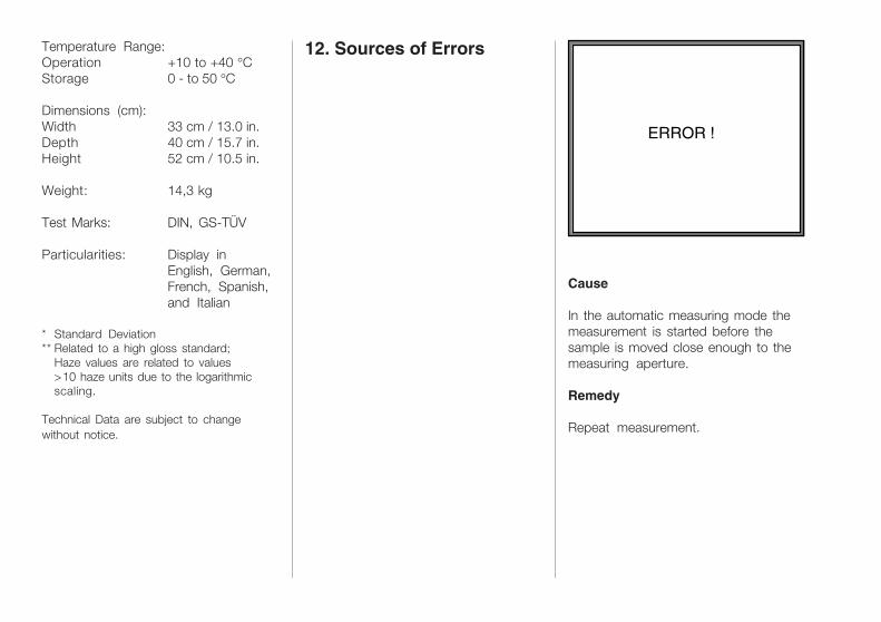
12. Sources of Errors
ERROR !
Cause
In the automatic measuring mode themeasurement is started before thesample is moved close enough to themeasuring aperture.
Remedy
Repeat measurement.
12. Sources of Errors
ERROR !
Cause
In the automatic measuring mode themeasurement is started before thesample is moved close enough to themeasuring aperture.
Remedy
Repeat measurement.
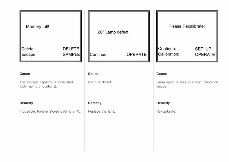
Memory full!
Delete:Escape:
DELETESAMPLE
Cause
Lamp is defect.
Remedy
Replace the lamp.
20° Lamp defect !
Continue:
OPERATE
Please Recalibrate!
Continue:Calibration:
SET UPOPERATE
Cause
Lamp aging or loss of stored calibrationvalues.
Remedy
Re-calibrate.
Cause
The storage capacity is exhausted(600 memory locations).
Remedy
If possible, transfer stored data to a PC.
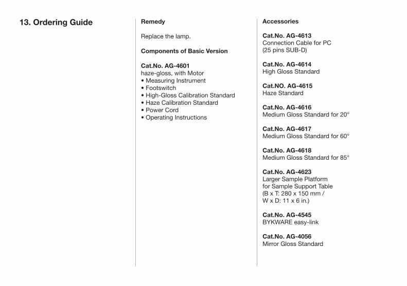
Remedy
Replace the lamp.
Components of Basic Version
Cat.No. AG-4601haze-gloss, with Motor• Measuring Instrument• Footswitch• High-Gloss Calibration Standard• Haze Calibration Standard• Power Cord• Operating Instructions
13. Ordering Guide Accessories
Cat.No. AG-4613Connection Cable for PC (25 pins SUB-D)
Cat.No. AG-4614High Gloss Standard
Cat.NO. AG-4615Haze Standard
Cat.No. AG-4616Medium Gloss Standard for 20°
Cat.No. AG-4617Medium Gloss Standard for 60°
Cat.No. AG-4618Medium Gloss Standard for 85°
Cat.No. AG-4623Larger Sample Platformfor Sample Support Table(B x T: 280 x 150 mm / W x D: 11 x 6 in.)
Cat.No. AG-4545BYKWARE easy-link
Cat.No. AG-4056Mirror Gloss Standard


haze-glossReflektometer
Best.-Nr. AG-4601
Gardner
haze-gloss
GardenerVersion: 2.6Copyright 1990
Gesamtansicht
228 012 718 EDFI 0811

Gardner
haze-gloss
GardenerVersion: 2.6Copyright 1990
Gesamtansicht
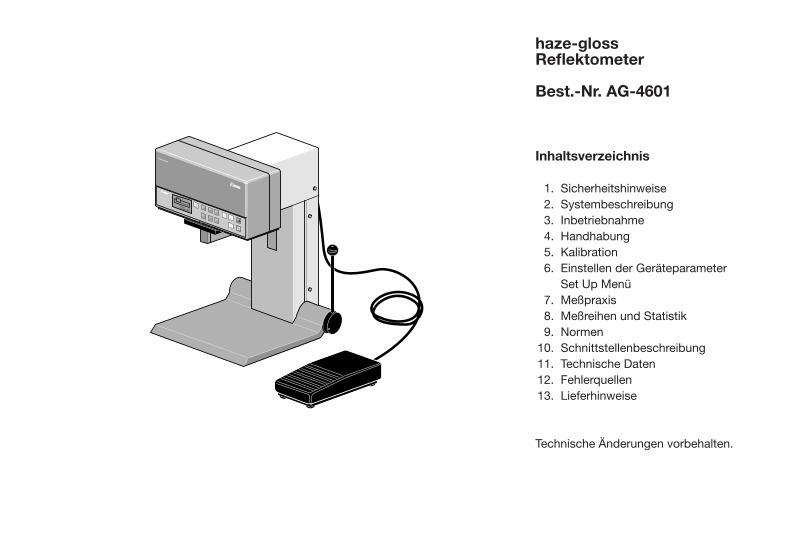
haze-glossReflektometer
Best.-Nr. AG-4601
Inhaltsverzeichnis
1. Sicherheitshinweise 2.Systembeschreibung 3.Inbetriebnahme 4.Handhabung 5.Kalibration 6.EinstellenderGeräteparameter SetUpMenü 7.Meßpraxis 8.MeßreihenundStatistik 9.Normen10.Schnittstellenbeschreibung11.TechnischeDaten12.Fehlerquellen13.Lieferhinweise
TechnischeÄnderungenvorbehalten.

Gardner
haze-gloss
BYK
GardenerVersion: 2.6Copyright 1990
Gesamtansicht
NetzschalterNetzspannungswahlSicherungen
Anschlüsse für: RS 232FußschalterNetzkabel
TastenfeldLCD Anzeige
Probentisch
Handhebel zum Öffnen des Probentisches
Fußschalter zum automatischen Öffnen des Probentisches

1. Sicherheitshinweise Vor dem Einschalten des Gerätes ist sicherzustellen, daß die am Geräteingestellte Betriebsspannung und die Netzspannung übereinstimmen. DerNetzstecker darf nur in eine Steckdose mit Schutzkontakt eingeführt werden. Die Schutzwirkung darf nicht durch eine Verlängerungsleitung ohne Schutzleiter aufgehoben werden.
Warnung! Jegliche Unterbrechung des Schutzleiters innerhalb oder außerhalb des Gerätes oder Lösen des Schutzleiteranschlusses kann dazu führen, daß das Gerät gefahrbringend wird. Absichtliche Unterbrechung ist nicht zulässig.
Abgleich, Austausch von Teilen, War-tung und Instandsetzung:Beim Öffnen von Abdeckungen oder Entfernen von Teilen, außer wenn dies von Hand möglich ist, können spannungsführende Teile freigelegt werden. Auch können Anschlußstellen spannungsführend sein. Vor einem Abgleich, einer Wartung, einer Instandsetzung oder einem Austausch von Teilen muß das Gerät von allen Spannungsquellen getrennt sein, wenn ein Öffnen des Gerätes erforderlich ist. Wenn danach ein Abgleich, eine Wartung oder eine Reparatur am geöffneten Gerät unter
Spannung unvermeidlich ist, so darf das nur durch eine Fachkraft geschehen, die mit den damit verbundenen Gefahren vertraut ist. Kondensatoren im Gerät können noch geladen sein, selbst wenn das Gerät von allen Spannungsquellen getrennt wurde. Es ist sicherzustellen, daß nur Sicherungen vom angegebe nen Typ und der angegebenen Nennstromstärke als Ersatz verwendet werden. Die Verwendung geflickter Sicherungen oder Kurzschließen des Sicherungsschalters ist unzulässig.
Fehler und außergewöhnliche Bean-spruchungenWenn anzunehmen ist, daß ein gefahrloser Betrieb nicht mehr möglich ist, so ist das Gerät außer Betrieb zu setzen und gegen unabsichtlichen Betrieb zu sichern. Es ist anzunehmen, daß ein gefahrloser Betrieb nicht mehr möglich ist:
• wenn das Gerät sichtbare Beschädigungen aufweist
• wenn das Gerät nicht mehr arbeitet
• nach längerer Lagerung unter ungünstigen Verhältnissen
• nach schweren Transport beanspruchungen

Das Reflektometer haze-gloss ist ein stationäres Meßgerät zur Bestimmung von Glanzgrad und Glanzschleier (Reflection Haze) bei Lackbeschichtungen, Kunststoffen, Bindemitteln und Pigmenten sowie Metalloberflächen (Spiegelglanz).
Die Oberfläche der Probe wird unter einem definierten Winkel angestrahlt und das reflektierte Licht fotoelektrisch gemessen. Der zu verwendendeEinstrahlwinkel (Geometrie) richtet sich danach, ob die Prüffläche eher in den „Meßbereich” matt, mittel oder hochglänzend fällt (Abgrenzung siehe Kapitel 6 Meßpraxis).
Durch den Einsatz fortschrittlicher Technologien in Entwicklung und Produktion konnte das Leistungsspektrum, der Bedienungskomfort und die Genauigkeit in bisher nicht gekanntem Maße realisiert werden:
• Drei Geometrien: 20°, 60° und 85° Meßbereich Spiegelglanz für Metall oberflächen, Glanzschleiermessung (Reflection Haze)
• Andruckvorrichtung für schnellen Probenwechsel, optional per Fußschalter motorisch zu betätigen
• Exakte Probenpositionierung durch projiziertes Fadenkreuz
• Übersichtliches Tastenfeld und prozessorgesteuerte Überwachung des Meßvorgangs
• Hohe Genauigkeit und Langzeitstabi lität durch Referenzstrahlengang
• Ohne Aufwärmzeit sofort betriebsbe reit, Langzeitkalibrierung (ca. alle 2 Monate)
• Eingebaute Statistikfunktion und Speicherung
• Schnittstelle zur Datenübertragung und Gerätesteuerung über PC
• Bedienerführung umschaltbar in den Sprachen Deutsch, Englisch, Französisch, Spanisch, Italienisch
Das haze-gloss entspricht den Normen der DIN 67 530, ISO 2813 und ASTM D 523.
2. Systembeschreibung
3. Inbetriebnahme Wichtige Hinweise vor der Inbetrieb-nahme:
Das System ist nicht auf einen speziellen Meßraum angewiesen. Man sollte jedoch die bei elektronischen Geräten üblichen Betriebsbedingungen einhalten.
Vermeiden Sie:
• Übermäßige Schwingungen und Vibrationen
• Extreme Umgebungstemperaturen
• Schnelle Temperaturänderungen
• Luftfeuchtigkeit über 85 %, Spritzwasser
• Ätzende und explosive Chemikalien, Dämpfe und Gase
• Extreme elektromagnetische Felder
• Heftige elektrostatische Entladungen
• Das Eindringen von Fremdkörpern in die Meßöffnung
Das Gerätegehäuse ist gegen eine Reihe von Lösemitteln beständig. Jedoch kann eine Beständigkeit nicht für alle Chemikalien gewährleistet werden. Benutzen Sie daher zur Reinigung ein weiches feuchtes Tuch. Bei grober Verschmutzung kann auch etwas Spiritus oder Seifenlauge verwendet werden.
Sollte eine Störung an Ihrem haze-gloss auftreten, so bitten wir Sie, keineeigenständigen Reparaturversuche vorzunehmen. Unser technischer Kundendienst wird Ihnen gerne und schnellstens weiterhelfen.
Anschlüsse
TYP
CAT.-NR.
F-NR.
4601
9017571
110/220 V 50/60 HZ 250 VA
USE ONLY WITH 250 V
FUSES / EMPLOYERUNIQUEMENT AVEC
DES FUIBLES WITH 250 V
110-120 V
220-
240
V
haze-gloss
Verpackung mit Person
SpannungsumschaltungSicherung
RS 232 Schnittstelle
Fußschalter
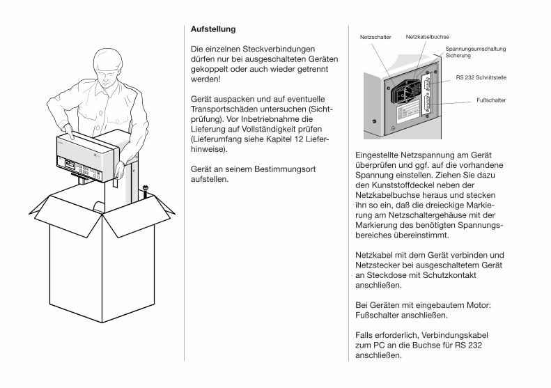
Netzschalter NetzkabelbuchseAufstellung
Die einzelnen Steckverbindungen dürfen nur bei ausgeschalteten Geräten gekoppelt oder auch wieder getrennt werden!
Gerät auspacken und auf eventuelle Transportschäden untersuchen (Sichtprüfung). Vor Inbetriebnahme die Lieferung auf Vollständigkeit prüfen (Lieferumfang siehe Kapitel 12 Lieferhinweise).
Gerät an seinem Bestimmungsort aufstellen.
Eingestellte Netzspannung am Gerät überprüfen und ggf. auf die vorhandene Spannung einstellen. Ziehen Sie dazu den Kunststoffdeckel neben derNetzkabelbuchse heraus und stecken ihn so ein, daß die dreieckige Markierung am Netzschaltergehäuse mit der Markierung des benötigten Spannungsbereiches übereinstimmt.
Netzkabel mit dem Gerät verbinden und Netzstecker bei ausgeschaltetem Gerät an Steckdose mit Schutzkontaktanschließen.
Bei Geräten mit eingebautem Motor: Fußschalter anschließen.
Falls erforderlich, Verbindungskabel zum PC an die Buchse für RS 232anschließen.
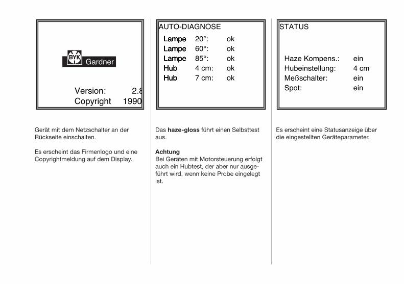
Gerät mit dem Netzschalter an der Rückseite einschalten.
Es erscheint das Firmenlogo und eine Copyrightmeldung auf dem Display.
Das haze-gloss führt einen Selbsttest aus.
AchtungBei Geräten mit Motorsteuerung erfolgt auch ein Hubtest, der aber nur ausgeführt wird, wenn keine Probe eingelegt ist.
Es erscheint eine Statusanzeige über die eingestellten Geräteparameter.
Version: 2.8Copyright 1990
Gardner
AUTO-DIAGNOSELampeLampeLampeHubHub
LampeLampeLampeHubHub
LampeLampeLampeHubHub
20°:60°:85°:4 cm:7 cm:
okokokokok
STATUS
Haze Kompens.:Hubeinstellung:Meßschalter:Spot:
ein4 cmeinein
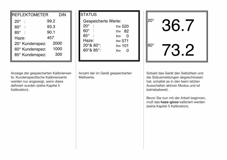
Anzeige der gespeicherten Kalibrierwerte. Kundenspezifische Kalibrierwerte werden nur angezeigt, wenn diese definiert wurden (siehe Kapitel 5 Kalibration).
Anzahl der im Gerät gespeicherten Meßwerte.
Sobald das Gerät den Selbsttest und die Statusmeldungen abgeschlossen hat, schaltet es in den beim letzten Ausschalten aktiven Modus und istbetriebsbereit.
Bevor Sie nun mit der Arbeit beginnen, muß das haze-gloss kalibriert werden (siehe Kapitel 5 Kalibration).
REFLEKTOMETER20° :60° :85° :Haze:20° Kundenspez:60° Kundenspez:85° Kundenspez:
99.293.390.1457 2000 1000 300
DIN20° 36.760° 73.2
STATUSGespeicherte Werte:20° :60° :85° :Haze:20°& 60°:60°& 85°:
n= 520n= 82n= 0n= 571n= 101n= 0
haze 20° 60° 85°
20° + 60° auto-range 60° + 85°
sample/statistic
results
delete
set up
operate
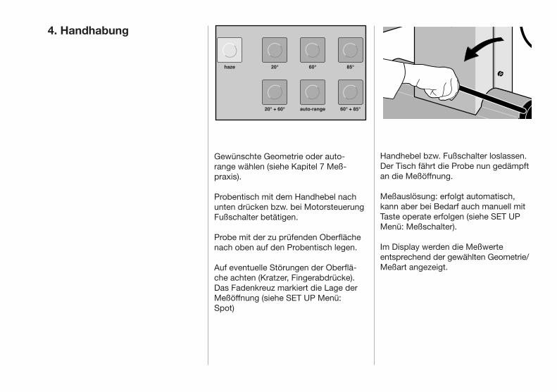
4. Handhabung
Handhebel bzw. Fußschalter loslassen. Der Tisch fährt die Probe nun gedämpft an die Meßöffnung.
Meßauslösung: erfolgt automatisch, kann aber bei Bedarf auch manuell mitTaste operate erfolgen (siehe SET UP Menü: Meßschalter).
Im Display werden die Meßwerte entsprechend der gewählten Geometrie/ Meßart angezeigt.
Gewünschte Geometrie oder auto range wählen (siehe Kapitel 7 Meßpraxis).
Probentisch mit dem Handhebel nach unten drücken bzw. bei MotorsteuerungFußschalter betätigen.
Probe mit der zu prüfenden Oberfläche nach oben auf den Probentisch legen.
Auf eventuelle Störungen der Oberfläche achten (Kratzer, Fingerabdrücke). Das Fadenkreuz markiert die Lage der Meßöffnung (siehe SET UP Menü: Spot)

5. Kalibration
Durchführung der Kalibration
• SET UP Menü aufrufen
set up
Aufgrund neuer Technologien und dem Referenzstrahlprinzip des haze-gloss ist eine Kalibrierung nur selten erforder-lich. Als Richtlinie sei ein Kalibrationsin-tervall von zwei Monaten empfohlen.
Außerdem raten wir zur Kalibration:
• bei starker Änderung der Umge- bungstemperatur
• wenn das haze-gloss Sie zum Kalibrieren auffordert (das Gerät erkennt selbständig eine Lampen- alterung um 4 %)
SET UP BEDIENUNG Cursor: SET UP Aendern: OPERATE
Weiter: SET UP
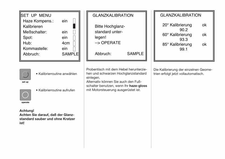
Probentisch mit dem Hebel herunterzie-hen und schwarzen Hochglanzstandard einlegen. Alternativ können Sie auch den Fuß-schalter benutzen, wenn Ihr haze-gloss mit Motorsteuerung ausgerüstet ist.
Die Kalibrierung der einzelnen Geome-trien erfolgt jetzt vollautomatisch.
operate
• Kalibrierroutine anwählen
• Kalibrierroutine aufrufen
Achtung!Achten Sie darauf, daß der Glanz-standard sauber und ohne Kratzer ist!
set up
SET UP MENU Haze Kompens.: Kalibrieren Meßschalter: Spot: Hub: Kommastelle: Abbruch:
ein
einein4cmeinSAMPLE
GLANZKALIBRATION Bitte Hochglanz-standard unter-legen!
--> OPERATE
Abbruch:
SAMPLE
GLANZKALIBRATION 20° Kalibrierung ok
90.2 60° Kalibrierung ok
93.3 85° Kalibrierung ok
99.1

operate
sample/statistic
Kalibrierung des Hazewertes
Weiße Hazekachel einlegen.Der Hazestandard muß sauber und kratzerfrei sein!
• operate Taste betätigen
AchtungDer auf dem Hazestandardaufgedruckte Wert ist hellbezugskom-pensiert (Kapitel 6 Haze Kompens.).
Kundenspezifische Kalibration
Für Spiegelglanzmessungen haben Sie die Möglichkeit auf Ihre hausinternenStandards zu kalibrieren und spezifische Reflektometerwerte vorzugeben, auf die jede weitere Messung bezogen wird.
• Aufruf des SET UP Menüs und Selektieren des Menü- punktes „Kundenspezifi- sche Mess. definieren“ (2. Menüseite)
• Aufruf „Kundenspezifische Mess. definieren“
• Gewünschte Geometrie wählen
Die Kalibrierung ist abgeschlossen.
Durch Betätigen der Taste sample/statistik erfolgt Sprung in den Meßmodus.
Wichtig!Kalibrieren Sie das haze-gloss nur mit den beigelegten Standards. Diesesind gegen amtlich geprüfte Primär-standards kalibriert und entsprechen DIN 67 530 bzw. ASTM D 523. Sollte ein Standard beschädigt werden oder verloren gehen, muß das haze-gloss von unserem technischen Kunden-dienst auf neue Standards kalibriert werden, da die Werte Ihrer Standards intern im Gerät gespeichert sind.
set up
operate
HAZEKALIBRATION Bitte Hazestandard unterlegen! --> OPERATE
Abbruch:
SAMPLE
HAZEKALIBRATION Hazekalibration ok457
KUNDENSPEZ. KALIB.SPIEGELMODUS 20°: nicht def. 60°: Wert: 1000 85°: nicht def.
Abbruch:
SAMPLE
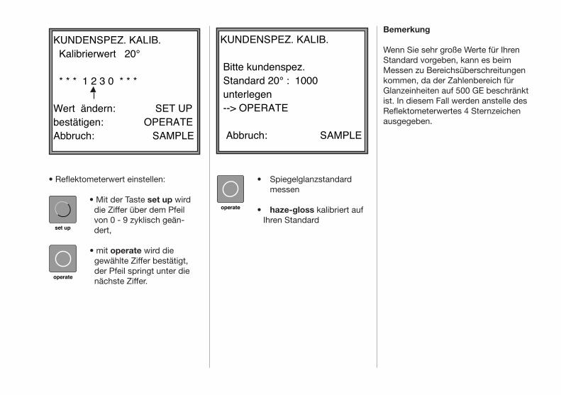
• Spiegelglanzstandard messen
• haze-gloss kalibriert auf Ihren Standard
operate
• Reflektometerwert einstellen:
• Mit der Taste set up wird die Ziffer über dem Pfeil von 0 - 9 zyklisch geän- dert,
• mit operate wird die gewählte Ziffer bestätigt, der Pfeil springt unter die nächste Ziffer.
set up
operate
Bemerkung
Wenn Sie sehr große Werte für Ihren Standard vorgeben, kann es beim Messen zu Bereichsüberschreitungen kommen, da der Zahlenbereich für Glanzeinheiten auf 500 GE beschränkt ist. In diesem Fall werden anstelle des Reflektometerwertes 4 Sternzeichen ausgegeben.
KUNDENSPEZ. KALIB.
Bitte kundenspez. Standard 20° : 1000 unterlegen --> OPERATE
Abbruch:
SAMPLE
KUNDENSPEZ. KALIB. Kalibrierwert 20° * * * 1 2 3 0 * * * Wert ändern: bestätigen:Abbruch:
SET UPOPERATE SAMPLE

6. Einstellen der Geräteparameter SET-UP Menü
Der selektierte Menüpunkt wird durch ein ausgefülltes Quadrat gekenn- zeichnet (Cursor).
Im SET UP Menü werden die Gerätepa-rameter eingestellt bzw. die Kalibrier-routine aufgerufen.
• Aufruf des SET UP Menüs
• Es erscheint ein Hinweis zur Bedienung.
• Nochmaliges Betätigen der Taste set up ruft die erste SET UP -Seite auf.
• Durch weiteres Betätigen der set up Taste wählen Sie die einzelnen Menü- punkte der Reihe nach an.
set up
set up
set up
SET UP BEDIENUNG Cursor: SET UP Aendern: OPERATE
Weiter: SET UP
SET UP MENU Haze Kompens.: Kalibrieren Meßschalter: Spot: Hub: Kommastelle: Abbruch:
ein
einein4cmeinSAMPLE

• Aufrufen oder Umschalten der selektierten Funktion.
• Verlassen des Set Up Menüs.
Erläuterung der einzelnen Menüpunkte
Haze Kompens. (Hellbezugskompensation)Mit einem gesonderten Detektor wird das von der Probe diffus gestreute Licht aufgenommen und wahlweise von den Hazewerten subtrahiert. Dieser Effekt wird naturgemäß um so gravierender, je heller die Probe ist (z.B. Weißlack). Im Modus „Haze Kompens.: aus” erscheint in der Anzeige der Hazewerte „nk.” für “nicht kompensiert”.Pigmentierte Proben wie z.B. Lak-ke oder Kunststoffe sollten stets mit Kompensation „ein“ gemessen werden, da die Probenhelligkeit den Hazewert beeinflußt.
KalibrierenAufruf der Kalibrierroutine (Siehe Kapitel 5 Kalibration).
MeßschalterBeim Hochfahren des Probentisches wird automatisch eine Messung aus-gelöst, so daß sich die Betätigung der Taste operate erübrigt.
Ausschnitt Sensor
BYK
GardenerVersion: 2.6Copyright 1990
haze
20°
60°
85°
20° + 60°auto-range
60° + 85°
sample/statistic results
delete
set up
operate
operate
sample/statistic
SpotAutomatisches Einschalten der Meß-fleckmarkierung bei der Abwärtsbewe-gung des Probentisches.
HubHier kann bei motorbetriebener Proben-tischauslenkung der Hub auf 4 cm oder 7 cm eingestellt werden.
KommastelleBei der Einstellung “Kommastelle aus” werden die Nachkommastellen derMeßergebnisse nicht angezeigt.Die Berechnungen im Statistik-Modus erfolgen weiterhin mit den nicht gerun-deten Werten.
SET UP MENU Sprache D,US,F,I,E Spiegelmodus: Kundenspezifische Mess. definieren Kundenspezifische Messung: Abbruch:
ein
einSAMPLE

Sprache D, US, F, I, EUmstellung der Sprache zwischen Deutsch, Englisch, Französisch, Italienisch und Spanisch.Die jeweils eingeschaltete Sprache ist angezeigt.
Spiegelmodusaus: Bei Glanzwerten größer als ca. 190 schaltet das haze-gloss automatisch auf einen niedriger verstärkenden Kanal um und mißt erneut. ein: Falls sie ausschließlich stark re- flektierende Proben (Metalle) messen, können Sie mit dem Spiegelglanzmodus die Meßzeit verkürzen.
Kundenspezifische Mess. definierenHier können Sie auf Ihr eigenes Spie-gelglanznormal mit einem von Ihnen einzugebenden Reflektometerwert kalibrieren. (Siehe Kapitel 5 Kalibration).
Kundenspezifische Messung(erscheint nur wenn definiert)Einschalten der Berechnung der Reflektometerwerte bezüglich einemkundenspezifischen Spiegelglanz-Standard.
Glanzmessung
Nach DIN 67 530 ist der Reflektome-terwert auf ein Schwarzglasnormal mit einem Brechungsindex von 1,567 (Reflektometerwert 100) bezogen. Die Reflektometer werden nach dem Einstrahlwinkel der Beleuchtungsein-richtung unterschieden. In der DIN 67 530 sind die Winkel 20°, 60° und 85¯° festgelegt und in den Anwendungsbe-reichen folgendermaßen abgegrenzt:
• Mittelglänzende Oberflächen werden mit der 60° Einstrahlungsrichtung gemessen und sollten dort im Bereich von 10 bis 70 Glanzeinheiten liegen.
7. Meßpraxis
20° 36.760° 73.2

In diesem Modus erstreckt sich der Wertebereich der Glanzmessungbis: 2000 GE bei 20° 1000 GE bei 60° 160 GE bei 85°
bei werksseitiger Kalibrierung.
Da die Spiegelglanzmessung häufig auf firmeninterne Standards bezogen wird, wurde die Möglichkeit vorgesehen, auf kundenspezifische Standards zu kali-brieren (Kapitel 5 Kalibration).
• Hochglänzende Flächen, die in der 60° Geometrie Meßwerte von größer als 70 Einheiten zeigen, sollten unter 20° ausgemessen werden.
• Matte Flächen von weniger als 10 Glanzeinheiten (bei 60°) werden mit der 85° Geometrie gemessen.
Um eine bessere Differenzierung der Meßwerte zu erreichen, wird empfohlen, den 85° Einstrahlungswinkel schon dann anzuwenden, wenn der 60° Wert unter 30 Einheiten liegt.Die Abgrenzung des Anwendungsberei-ches wird in den verschiedenen Nor-mungen unterschiedlich gehandhabt. Beispielsweise werden als obere Grenze für den Wechsel von der 60° zur 85° Geometrie bei der ASTM D 532 10 Glanzeinheiten angegeben, während es bei der ISO 2813 30 Einheiten sind. Die Grenzwerte sind jedoch eher als Empfehlungen anzusehen.
Spiegelglanzmessung
Das haze-gloss bietet einen erweiter-ten Meßbereich, so daß auch Proben mit sehr großem Reflexionsvermögen (polierte Metalloberflächen, Spiegel) ausgemessen werden können.
Bemerkungen
• Im Modus Autorange wird bei Reflektometerwerten kleiner als 30 auf die Doppelgeometrie 60°/85° geschaltet, bei Reflektometerwerten zwischen 30 und 70 auf die Einzelgeometrie 60° und bei Reflektometerwerten größer 70 auf die Doppelgeometrie 20°/60° (Reflektometerwerte jeweils bei 60°).
• Die Messung an verschmutzten, verkratzten oder anderweitig
gestörten Bereichen des Prüflings ist nicht sinnvoll, es sei denn, daß man mittels Glanzmessung eine Aussage über den Grad derartiger Störungen erzielen will.
AUTO-RANGE60° 20.785° 47.2

• Nur an ebenen Flächen sind einwand-freie Messungen möglich.
• Da man nicht davon ausgehen kann, daß das Glanzvermögen über die gesamte Oberfläche des Prüflings konstant ist, sollte der Reflektometer-wert an mehreren, verschiedenen Stellen bestimmt und der Mittelwert herangezogen werden.
• Wenn die Proben eine Struktur bzw. eine richtungsabhängige Glanzeigen-schaft aufweisen, sollte man die Strukturmerkmale der Proben und die
Lichteinfallrichtung bei der Messung im Prüfbericht angeben oder den Mittelwert aus Meßwerten in verschie-denen Richtungen nehmen.
• Proben, die im Verlauf einer Untersu-chung mehrfach gemessen werden müssen (z.B. Bewitterungsproben), sollten entsprechend markiert wer-den, um bei wiederholter Prüfung ein Messen an der selben Stelle sicher-zustellen.
Die Haze-Messung erfüllt dann folgende Aufgaben:
• Bessere Differenzierung der opti- schen Eigenschaften hochglänzen- der Oberflächen.
• Indirektes Maß zur Beurteilung von Lack bzw. Rohstoffeigenschaften, z.B. - Dispergierverhalten - Flockulationsneigung - Benetzungsvermögen - Waschkratzerbeständigkeit - zusätzliche Informationen bei der Bewitterungsprüfung - zur Optimierung von Lack- rezepturen • Indirektes Maß zur Beurteilung von Oberflächenbearbeitungsverfahren
Haze-Messung
• Taste haze betätigen
Falls im SET UP Menü Haze Kompensation: aus eingestelltwurde, erscheint der Hinweis nk. für „nicht kompensiert” im linken oberen Teil des Displays. Der Reflektometerwert allein genügt oft nicht, um die optischen Eigenschafteneiner Oberfläche ausreichend zu beschreiben. Neben Farbe und Glanz hat auch der Glanzschleier hohe Bedeutung.
haze
Hazenk. 13.720° 86.5

Die Formel
Die Formel für den Hazewert lautet:
H = K x lg (linearer Haze/20 +1)
Die Konstante (K=1285,1) wurde so gewählt, daß sich bei einem linearen Haze von 100 HE ein logarithmischer Wert von 1000 ergibt.
Bemerkung
Der Haze-Wert wird logarithmisch dargestellt
- um der menschlichen Wahrnehmung von Glanzschleier entgegen zu kommen
- um bei kleinen Haze-Werten eine höhere Empfindlichkeit zu erreichen (je kleiner der Haze-Wert, um so besser die Oberfläche)
Zur Messung des Glanzschleiers sind zusätzlich zur 20° Geometrie zwei weitere um 1,8° versetzte Blenden (c) angebracht durch die das Streulicht nahe der Hauptreflexionsrichtung detektiert wird.
haze
20 020 0
60 0
60 0
85 0
85 0
a
b
c
a

Der Statistik-Modus kann in jeder Geometrie angewählt werden. Nur die AUTO-RANGE Funktion kann allein bei Einzelmessung betrieben werden.
• Taste sample/statistic Umschalten zwischen Ein- zelmessungen und Meßrei- hen.
Zeichenerklärung:n = Nummer der Messungm = Mittelwerts = Standardabweichung
Anzeige der vollständigen Statistik-ergebnissem Mittelwertn Anzahl der Messungenmin kleinster Meßwertmax größter Meßwerts Standardabweichung
vr Variationskoeffizient vr =100 S/m (%)
sample/statistic
8. Meßreihen und Statistik 20°36.7
60°73.4
n=123m=36.5 s= 1.3
m=73.3 s= 0.9
s= 1 /n-1 ∑(xi-x)2n
i=1
-
20° m= 36.5 min= 32.8 max= 40.6
60° m= 73.3 min= 70.8 max= 75.7
n= 123 s= 1.3Vr= 3.6
s= 0.9Vr= 1.2
20°36.760°73.4
n=123m=36.5 s= 1.3
m=73.3 s= 0.9
s= 1 /n-1 ∑(xi-x)2n
i=1
-
20° m= 36.5 min= 32.8 max= 40.6
60° m= 73.3 min= 70.8 max= 75.7
n= 123 s= 1.3Vr= 3.6
s= 0.9Vr= 1.2

Bemerkungen
Die Meßwerte im Statistik-Modus werden gespeichert und bleiben auch bei Umschalten der Geometrie, bzw. in den Einzelmeßmodus erhalten.
Es können bis zu 600 Messungen pro Geometrie gespeichert werden, diese lassen sich über die RS 232-Schnitt-stelle auch an einen PC übertragen. Bei einem Geometriewechsel im Statistic-Mode werden die Werte der früher erstellten Meßreihe wieder angezeigt. Bei Bedarf kann die Serie fortgesetzt werden.
Während einer laufenden Meßserie im Statistikmodus darf nicht die Kalibrie-rung umgeschaltet werden (Kompensa-tion, Spiegelglanz, Kundenspezifisch), da dies die statistischen Ergebnisse verfälscht.
• Taste delete Letzte Messung löschen.
Die Zählvariable n wird um 1 erniedrigt. Sie können den letzten Wert nur löschen, wenn nach Ihrer Messung keine andere Funktion aufgerufen wurde.
• Taste results
results
delete
LOESCHEN Letzten Wert löschen : -->DELETE
Gesamtstatistik löschen : -->RESULTS
Abbruch:
SAMPLE
Gesamte Meßreihe der eingestellten Geometrie löschen.

9. Normen
DIN 67 530Reflektometer als Hilfsmittel zur Glanz-beurteilung an ebenen Anstrich- und Kunststoff-Oberflächen
ISO 2813 Paints and varnishes - Measurement of specular gloss of nonmetallic paint films at 20°, 60° and 85°
ANSI/ASTM D 523 Standard Test Method for Specular Gloss
ASTM D 2457 Standard Test Method for Specular Gloss of Plastic Films
BS 3900 (Part D2+D5) British Standard Methods of Test for Paints Gloss (Specular Reflection Value)
JIS Z 8741Method of Measurement for Specular Glossiness
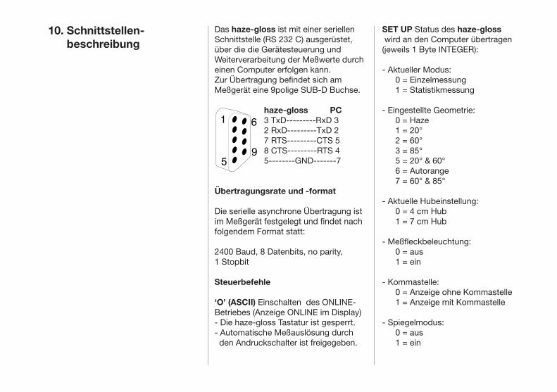
10. Schnittstellen- beschreibung
Das haze-gloss ist mit einer seriellen Schnittstelle (RS 232 C) ausgerüstet,über die die Gerätesteuerung und Weiterverarbeitung der Meßwerte durch einen Computer erfolgen kann.Zur Übertragung befindet sich am Meßgerät eine 9polige SUB-D Buchse.
haze-gloss PC3 TxD---------RxD 32 RxD---------TxD 27 RTS---------CTS 58 CTS---------RTS 45--------GND-------7
Übertragungsrate und -format
Die serielle asynchrone Übertragung ist im Meßgerät festgelegt und findet nachfolgendem Format statt:
2400 Baud, 8 Datenbits, no parity, 1 Stopbit
Steuerbefehle
‘O’ (ASCII) Einschalten des ONLINE-Betriebes (Anzeige ONLINE im Display)- Die haze-gloss Tastatur ist gesperrt.- Automatische Meßauslösung durch den Andruckschalter ist freigegeben.
SET UP Status des haze-gloss wird an den Computer übertragen(jeweils 1 Byte INTEGER):
- Aktueller Modus: 0 = Einzelmessung 1 = Statistikmessung
- Eingestellte Geometrie: 0 = Haze 1 = 20° 2 = 60° 3 = 85° 5 = 20° & 60° 6 = Autorange 7 = 60° & 85°
- Aktuelle Hubeinstellung: 0 = 4 cm Hub 1 = 7 cm Hub
- Meßfleckbeleuchtung: 0 = aus 1 = ein
- Kommastelle: 0 = Anzeige ohne Kommastelle 1 = Anzeige mit Kommastelle
- Spiegelmodus: 0 = aus 1 = ein
1 6
59
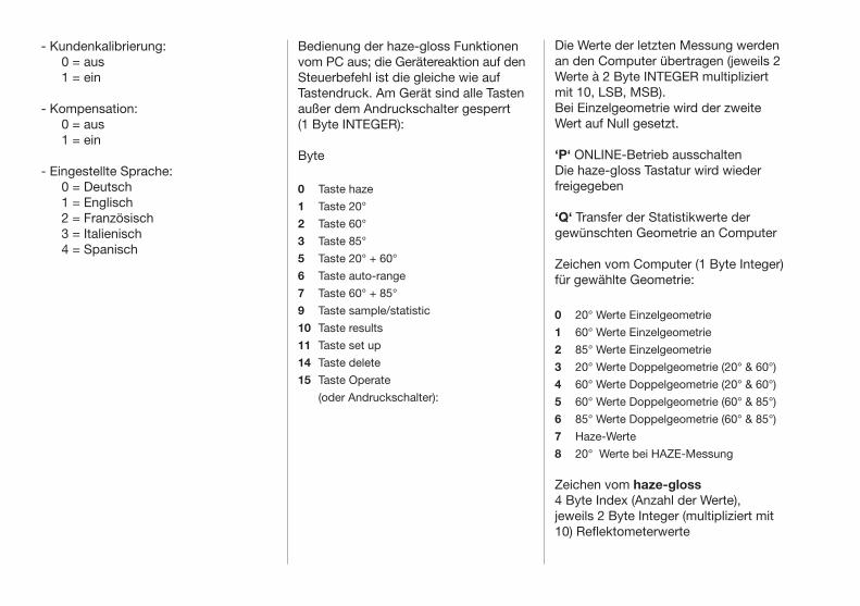
- Kundenkalibrierung: 0 = aus 1 = ein
- Kompensation: 0 = aus 1 = ein
- Eingestellte Sprache: 0 = Deutsch 1 = Englisch 2 = Französisch 3 = Italienisch 4 = Spanisch
Bedienung der haze-gloss Funktionen vom PC aus; die Gerätereaktion auf den Steuerbefehl ist die gleiche wie auf Tastendruck. Am Gerät sind alle Tasten außer dem Andruckschalter gesperrt (1 Byte INTEGER):
Byte
0 Taste haze
1 Taste 20°
2 Taste 60°
3 Taste 85°
5 Taste 20° + 60°
6 Taste auto-range
7 Taste 60° + 85°
9 Taste sample/statistic
10 Taste results
11 Taste set up
14 Taste delete
15 Taste Operate
(oder Andruckschalter):
Die Werte der letzten Messung werden an den Computer übertragen (jeweils 2 Werte à 2 Byte INTEGER multipliziert mit 10, LSB, MSB). Bei Einzelgeometrie wird der zweite Wert auf Null gesetzt.
‘P‘ ONLINE-Betrieb ausschaltenDie haze-gloss Tastatur wird wieder freigegeben
‘Q‘ Transfer der Statistikwerte dergewünschten Geometrie an Computer
Zeichen vom Computer (1 Byte Integer) für gewählte Geometrie:
0 20° Werte Einzelgeometrie
1 60° Werte Einzelgeometrie
2 85° Werte Einzelgeometrie
3 20° Werte Doppelgeometrie (20° & 60°)
4 60° Werte Doppelgeometrie (20° & 60°)
5 60° Werte Doppelgeometrie (60° & 85°)
6 85° Werte Doppelgeometrie (60° & 85°)
7 Haze-Werte
8 20° Werte bei HAZE-Messung
Zeichen vom haze-gloss4 Byte Index (Anzahl der Werte),jeweils 2 Byte Integer (multipliziert mit 10) Reflektometerwerte
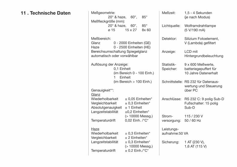
Meßzeit: 1,5 - 4 Sekunden (je nach Modus)
Lichtquelle: Wolframdrahtlampe (5 V/190 mA)
Detektor: Silizium Fotoelement, V (Lambda) gefiltert
Anzeige: LCD mit Hintergrundbeleuchtung
Statistik- 9 x 600 Meßwerte, Speicher: batteriegepuffert für 10 Jahre Datenerhalt
Schnittstelle: RS 232 für Datenaus- wertung und Steuerung über PC
Anschlüsse: RS 232 C: 9 polig Sub-D Fußschalter: 15 polig Sub-D
Strom- 115 / 230 Vversorgung: 50 / 60 Hz
Leistungs-aufnahme: 50 VA
Sicherung: 1 AT (230 V), 1,6 AT (115 V)
11 . Technische Daten Meßgeometrie: 20° & haze, 60°, 85°Meßfleckgröße (mm): 20° & haze, 60°, 85° ø 15 15 x 27 8x 60
Meßbereich:Glanz 0 - 2000 Einheiten (GE)Haze 0 - 2500 Einheiten (HE)Bereichsumschaltung Spiegelglanzautomatisch oder vorwählbar
Auflösung der Anzeige: 0,1 Einheit (im Bereich 0 - 100 Einh.) 1 Einheit (im Bereich > 100 Einh.)
Genauigkeit**:GlanzWiederholbarkeit ± 0,05 Einheiten*Vergleichbarkeit ± 0,3 Einheiten*Absolutgenauigkeit ± 1 EinheitLangzeitstabilität ±0,2 Einheiten* (> 10000 Messg.) Temperaturdrift 0,02 Einh. /°C*
HazeWiederholbarkeit ± 0,3 Einheiten*Vergleichbarkeit ± 2 Einheiten*Langzeitstabilität ± 0,3 Einheiten* (> 10000 Messg.)Temperaturdrift ± 0.2 Einh./°C*
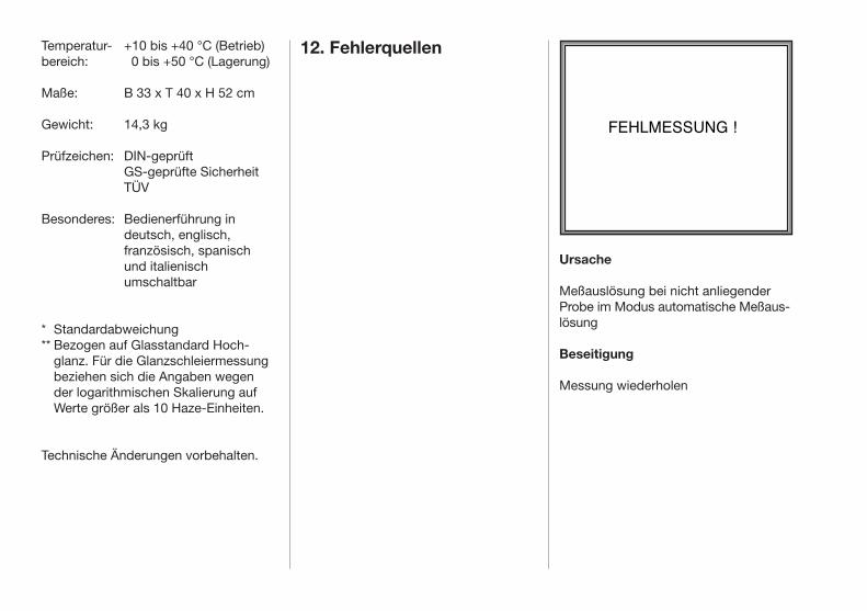
Temperatur- +10 bis +40 °C (Betrieb)bereich: 0 bis +50 °C (Lagerung)
Maße: B 33 x T 40 x H 52 cm
Gewicht: 14,3 kg
Prüfzeichen: DIN-geprüft GS-geprüfte Sicherheit TÜV
Besonderes: Bedienerführung in deutsch, englisch, französisch, spanisch und italienisch umschaltbar
* Standardabweichung** Bezogen auf Glasstandard Hoch-
glanz. Für die Glanzschleiermessung beziehen sich die Angaben wegen der logarithmischen Skalierung auf Werte größer als 10 Haze-Einheiten.
Technische Änderungen vorbehalten.
12. Fehlerquellen
Ursache
Meßauslösung bei nicht anliegender Probe im Modus automatische Meßaus-lösung
Beseitigung
Messung wiederholen
FEHLMESSUNG !
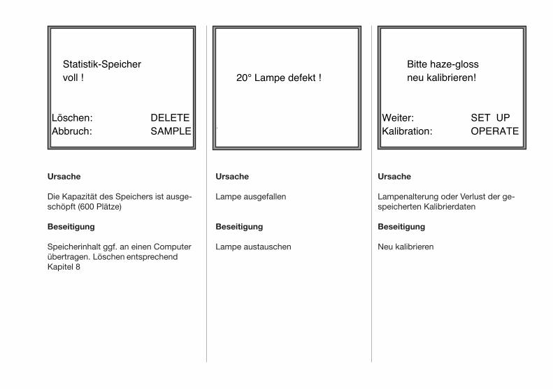
Ursache
Lampenalterung oder Verlust der ge-speicherten Kalibrierdaten
Beseitigung
Neu kalibrieren
Ursache
Die Kapazität des Speichers ist ausge-schöpft (600 Plätze)
Beseitigung
Speicherinhalt ggf. an einen Computer übertragen. Löschen entsprechend Kapitel 8
Ursache
Lampe ausgefallen
Beseitigung
Lampe austauschen
Statistik-Speicher voll !
Löschen:Abbruch:
DELETESAMPLE
20° Lampe defekt !
Weiter:
OPERATE
Bitte haze-gloss neu kalibrieren!
Weiter:Kalibration:
SET UPOPERATE

13. Lieferhinweise Zubehör
Best.-Nr. AG-4613 Verbindungskabel für PC 9/25 polig
Best.-Nr. AG-4614 Hochglanzstandard
Best.-Nr. AG-4615 Haze-Standard
Best.-Nr. AG-4616 Mittelglanzstandard für 20°
Best.-Nr. AG-4617 Mittelglanzstandard für 60°
Best.-Nr. AG-4618 Mittelglanzstandard für 85°
Best.-Nr. AG-4623 Zusatztisch zur Vergrößerung der Probenandruckvorrichtung (280 x 150 mm)
Best.-Nr. AG-4545 BYKWARE easy-link
Best.-Nr. AG-4056 Spiegelglanzstandard
Lieferumfang Grundgerät
Best.Nr. AG-4601 haze-gloss, mit Motor • Grundgerät• Fußschalter• Hochglanzstandard• Haze-Standard • Netzkabel• Bedienungsanleitung


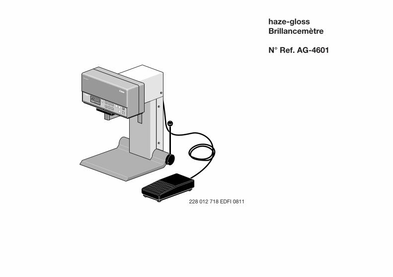
Gardner
haze-gloss
GardenerVersion: 2.6Copyright 1990
Gesamtansicht
haze-glossBrillancemètre
N° Ref. AG-4601
228 012 718 EDFI 0811


haze-glossBrillancemètre
N° Ref. AG-4601
Table des matières
1. Description du système 2. Démarrage 3. Fonctionnement 4. Etalonnage 5. Sélection des paramètres de l’instrument Menu Configuration "SET UP" 6. Indications particulières concernant les mesures 7. Mesures en série et statistiques 8. Spécifications internationales 9. Description de l’interface 10. Données techniques 11. Sources d’erreur 12. Liste des composants et accessoires
Sous réserve des modifications techniques
Gardner
haze-gloss
GardenerVersion: 2.6Copyright 1990
Gesamtansicht
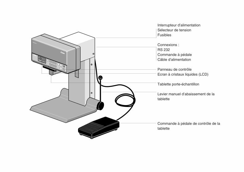
Gardner
haze-gloss
Gardner
BYK
GardenerVersion: 2.6Copyright 1990
haze
20°
60°
85°
20° + 60°auto-range
60° + 85°
sample/statistic results
delete
set up
operate
Interrupteur d’alimentationSélecteur de tensionFusibles
Connexions :RS 232Commande à pédaleCâble d’alimentation
Panneau de contrôleEcran à cristaux liquides (LCD)
Tablette porte-échantillon
Levier manuel d’abaissement de latablette
Commande à pédale de contrôle de latablette

commandeàpédaleenoption
• mirelumineusepourunpositionne- mentprécisdeséchantillons
• panneaudecontrôled'unegrande lisibilitéetfonctionnementcontrôlépar micro-processeur
• hauteprécisionetstabilitéàlong termegrâceauprincipedufaisceau deréférence
• pasde"tempsdechauffe“,utilisation immédiate,étalonnageàlongterme (touslesdeuxmoisenviron)
• modestatistiquesetsauvegarde internes
• interfacedetransfertetcontrôlede donnéesviaunPC
• sélectiondelalangueutiliséeàl’écran français,anglais,allemand,espagnol ouitalien
Lesystèmedemesurehaze-glossestconformeauxstandardsISO2813,ASTMD523etDIN67530.
Leréflectomètrehaze-gloss("voile-brillance“)estuninstrumentfixeconçupourmesurerlabrillancespéculaireetlevoilederéflexionpropresauxcouchesdepeintures,matièresplastiques,liants,pigmentsetsurfacesmétalliques(réflexionmiroir).
Lasurfacedel’échantillonestéclairéeselonunangledéfinietlalumièreréfléchiemesuréeàl’aided’unecellulephoto-électrique.Lasélectiondel’angled’éclairageapproprié(géométrie)dépendduniveaud’éclatparticulieràlasurfacedel’échantillon:mat,moyenouélevé.L’utilisationdecetteplagedemesureestcommentéeauchapitre6,"Indicationsparticulièresconcernantlesmesures“.
haze-gloss,développéetproduitenfaisantappelauxtechniqueslesplusavancées,offredesperformances,unefacilitéd’utilisationetuneprécisiond’unniveauencorejamaisatteint:
• troisgéométries:20°,60°et85°effetmiroirsurlessurfacesmétalliques,voilederéflexion
• dispositifdecalagedeséchantillons permettantdechangerrapidement cesderniers
• tabletteporte-échantillon,avec pilotageparmoteuretcontrôlepar
1. Description du système

• décharges électro-statiques élevées
• pénétration de corps étrangers dansl’orifice de mesure
Bien que le coffrage de l’instrument aitété étudié pour résister à l’action d’uncertain nombre de solvants, laprotection contre tous les agentschimiques ne peut être garantie. C’estpourquoi il est recommandé de nettoyerl’unité au moyen d’un chiffon doux àpeine humide. Pour les taches plusrésistantes, vous pouvez utiliser un peud’alcool ou de lessive.En cas de panne, n’essayez pasd’effectuer la réparation vous-même.Notre service après-vente sera heureuxde vous venir en aide dans les meilleursdélais.
2. Démarrage Remarques importantesVeuillez lire attentivement cesinformations avant de vous servir del’instrument.
Il n’est pas nécessaire de réserver ausystème haze-gloss un espaceparticulier mais, comme avec tous lesinstruments électroniques, un certainnombre de conditions d’exploitationdoivent être réunies.
Vous devez surtout éviter lessituations suivantes:
• oscillations et vibrations excessives
• températures ambiantes extrêmes
• grands écarts de température
• taux d’humidité ≥ 85%, leséclaboussures de liquides
• produits chimiques corrosifs ouexplosifs, les vapeurs agressives et
les gaz
• proximité de forts champs électromagnétiques
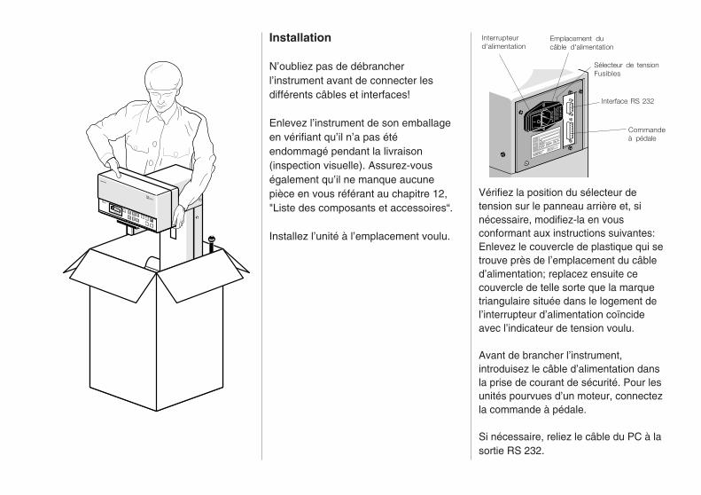
TYP
CAT.-NR.
F-NR.
4601
9017571
110/220 V 50/60 HZ250
VA
BYK-GARDENER GMBH
LAUSITZER STR. 8
8192 GERETSRIED 2
TELEFON (08171) 493-0
TELEX 5 27 851
TELEFAX (0871) 493-40
USE O
NLY W
ITH 250 V
FUSES / EM
PLOYER
UN
IQU
EMEN
T AVEC
DES FU
IBLES W
ITH 250 V
110-120 V
220-
240
V
Gardner
haze-gloss
Gardner
BYK
GardenerVersion: 2.6Copyright 1990
Interrupteurd'alimentation
Interface RS 232
Commandeà pédale
Sélecteur de tensionFusibles
Emplacement ducâble d'alimentation
Vérifiez la position du sélecteur detension sur le panneau arrière et, sinécessaire, modifiez-la en vousconformant aux instructions suivantes:Enlevez le couvercle de plastique qui setrouve près de l’emplacement du câbled’alimentation; replacez ensuite cecouvercle de telle sorte que la marquetriangulaire située dans le logement del’interrupteur d’alimentation coïncideavec l’indicateur de tension voulu.
Avant de brancher l’instrument,introduisez le câble d’alimentation dansla prise de courant de sécurité. Pour lesunités pourvues d’un moteur, connectezla commande à pédale.
Si nécessaire, reliez le câble du PC à lasortie RS 232.
Installation
N’oubliez pas de débrancherl’instrument avant de connecter lesdifférents câbles et interfaces!
Enlevez l’instrument de son emballageen vérifiant qu’il n’a pas étéendommagé pendant la livraison(inspection visuelle). Assurez-vouségalement qu’il ne manque aucunepièce en vous référant au chapitre 12,"Liste des composants et accessoires“.
Installez l’unité à l’emplacement voulu.

Version: 2.95Copyright 1991
Le haze-gloss effectue un test d’auto-diagnostic.
RemarqueLes unités pourvues d’un moteur testentégalement le déplacement vers le bas,à condition qu’aucun échantillon n’aitété inséré.
Le statut des divers paramètress’affiche à l’écran.
Gardner
AUTO DIAGNOSTIQUE
LampeLampeLampeHubHub
LampeLampeLampeHubHub
20°:60°:85°:4 cm:7 cm:
okokokokok
LampeLampeLampeDescenteDescente
Mettez l’unité sous tension à l’aide del’interrupteur d’alimentation situé sur lepanneau arrière.
Le logo et le texte de copyrights’affichent à l’écran.
STATUT
Haze Compens.:Descente:Mesure autom.:Spot:
on4 cmonon

20° 36.760° 73.2
Les valeurs d’étalonnage sauvegardéesapparaissent à l’écran. L’affichage desvaleurs d’étalonnage spécifiques auclient "Limite Etal." n’intervient que sicette fonction a été définie (voir chapitre4 Etalonnage).
Après le test d’auto-diagnostic etl’affichage du statut, l’instrument sereplace dans le dernier mode activéavant que l’unité soit déconnectée; il estprêt à fonctionner.
Avant de pouvoir effectuer desmesures, le haze-gloss doit êtreétalonné (voir chapitre 4 Etalonnage).
Le nombre de lectures sauvegardéesapparaît à l’écran.
REFLECTOMETRE20° :60° :85° :Haze:20° LIMITE ETAL.: 60° LIMITE ETAL.:85° LIMITE ETAL.:
91.995.399.4454.0
DIN
20001000 300
STATUT
Valeurs en Memoire:20° :60° :85° :Haze:20°& 60°:60°& 85°:
n= 720n= 82n= 0n= 671n= 101n= 0

haze 20° 60° 85°
20° + 60° auto-range 60° + 85°
Sélectionnez la géométrie voulue ou lafonction de réglage automatique "auto-range" (voir chapitre 6, Indicationsparticulières concernant les mesures).
Abaissez la tablette porte-échantillon aumoyen du levier manuel ou, le caséchéant, avec la commande à pédale.
Insérez l’échantillon surface à testervers le haut et vérifiez s’il ne présentepas de défauts (rayures, empreintesetc.). La mire lumineuse marque laposition de l’orifice de mesure (voirl’option "Spot“ dans le menu SET UP).
Relâchez le levier manuel ou lacommande à pédale. La tablette porte-échantillon rapproche à présentl’échantillon de l’orifice de mesure.
Les opérations de mesure commencentautomatiquement mais peuvent aussil’être manuellement en appuyant sur latouche opération (voir l’option "Mesureautom.“ dans le menu SET UP).
Les valeurs mesurées et le mode degéométrie/mesure correspondantapparaissent à l’écran.
3. Fonctionnement
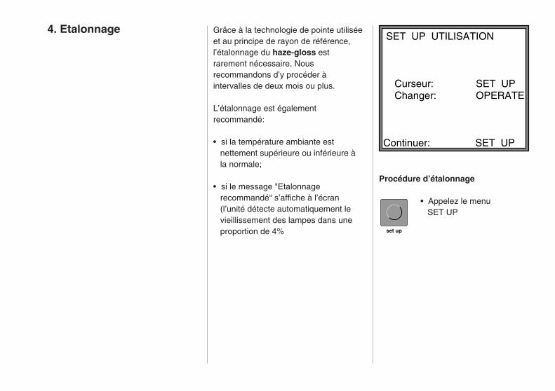
Grâce à la technologie de pointe utiliséeet au principe de rayon de référence,l’étalonnage du haze-gloss estrarement nécessaire. Nousrecommandons d’y procéder àintervalles de deux mois ou plus.
L’étalonnage est égalementrecommandé:
• si la température ambiante est nettement supérieure ou inférieure à la normale;
• si le message "Etalonnage recommandé“ s’affiche à l’écran (l’unité détecte automatiquement le vieillissement des lampes dans une proportion de 4%
SET UP UTILISATION
Curseur: SET UP Changer: OPERATE
Continuer: SET UP
4. Etalonnage
Procédure d’étalonnage
• Appelez le menu SET UP
set up
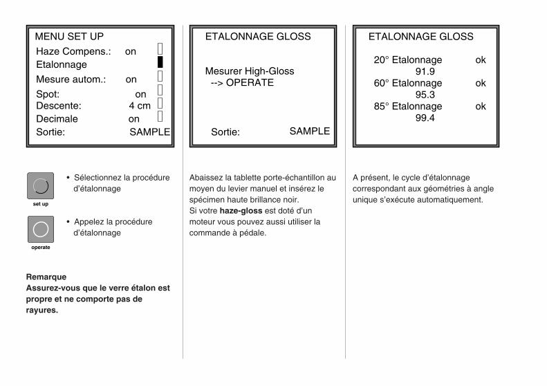
set up
operate
ETALONNAGE GLOSS
Mesurer High-Gloss--> OPERATE
SAMPLESortie:
ETALONNAGE GLOSS 20° Etalonnage ok 91.9
60° Etalonnage ok 95.3
85° Etalonnage ok 99.4
A présent, le cycle d’étalonnagecorrespondant aux géométries à angleunique s’exécute automatiquement.
Abaissez la tablette porte-échantillon aumoyen du levier manuel et insérez lespécimen haute brillance noir.Si votre haze-gloss est doté d’unmoteur vous pouvez aussi utiliser lacommande à pédale.
• Sélectionnez la procédure d’étalonnage
• Appelez la procédure d’étalonnage
RemarqueAssurez-vous que le verre étalon estpropre et ne comporte pas derayures.
MENU SET UP
Haze Compens.: onEtalonnage
Mesure autom.: on
Spot: onDescente: 4 cmDecimale onSortie: SAMPLE

sample/statistic
operate
ETALONNAGE HAZE Mesurer Haze Stand. --> OPERATE
SAMPLESortie:
ETALONNAGE HAZE Etal. Haze ok454.0
Etalonnage du voile
Insérez la tuile voilée blancheAssurez-vous que le voilé est propreet ne comporte pas de rayures.
• Appuyez sur la touche operate
RemarqueLa valeur indiquée sur le voilé a étéréduite du facteur de luminance (voirchapitre 5, Compensation voile).
L’étalonnage est terminé.
• Passez en mode Mesure en appuyant sur la touche sample/statistic (échantillon/statistiques)
Important!N’utilisez que les spécimens fournis avecl’instrument; ces derniers ont étéétalonnés et testés en fonction destandards reconnus et correspondent à lanorme ASTM D 523 ou DIN 67 530.Si l’un d’entre eux s’avère endommagé ouperdu, le haze-gloss doit être ré-étalonnépar nos techniciens en fonction denouveaux étalons, car l’instrumentconserve les valeurs des étalonsoriginaux.
operate
Etalonnage spécifié par le client
Pour mesurer la réflexion miroir, vouspouvez étalonner l’instrument selon lesstandards propres à votre entreprise etdéfinir des valeurs de réflectomètrespécifiques. Toutes les mesures futuresseront alors conditionnées par cesvaleurs.
• Appelez le menu SET UPet sélectionnez "ChangerEtal. Val.“ (2ème page du menu).
• Appuyez sur la toucheopération pour définir les
paramètres de l’option"Changer Etal. Val."
• Sélectionnez la géométrie voulue.
set up
LIMITE ETAL. SPEC. MODE MIROIR 20°: pas defini 60°: Val.1000 85°: pas defini
Sortie:
SAMPLE
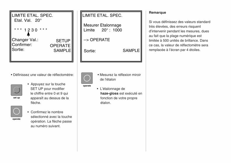
Remarque
Si vous définissez des valeurs standardtrès élevées, des erreurs risquentd’intervenir pendant les mesures, duesau fait que la plage numérique estlimitée à 500 unités de brillance. Dansce cas, la valeur de réflectomètre seraremplacée à l’écran par 4 étoiles.
LIMITE ETAL. SPEC. Etal. Val. 20° * * * 1 2 3 0 * * * Changer Val.: Confirmer:Sortie:
SETUPOPERATE SAMPLE
set up
operate
• Définissez une valeur de réflectomètre:
• Appuyez sur la touche SET UP pour modifier le chiffre entre 0 et 9 qui apparaît au dessus de la
flèche.
• Confirmez le nombresélectionné avec la toucheopération. La flèche passeau numéro suivant.
• Mesurez la réflexion miroir de l'étalon
• L’étalonnage de haze-gloss est exécuté en fonction de votre propre étalon.
LIMITE ETAL. SPEC.
Mesurer Etalonnage Limite 20° : 1000 --> OPERATE
SAMPLESortie:
operate
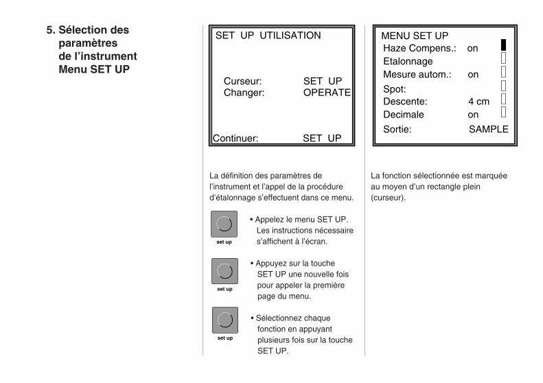
SET UP UTILISATION
Curseur: SET UP Changer: OPERATE
Continuer: SET UP
set up
set up
set up
La définition des paramètres del’instrument et l’appel de la procédured’étalonnage s’effectuent dans ce menu.
• Appelez le menu SET UP. Les instructions nécessaire s’affichent à l’écran.
• Appuyez sur la touche SET UP une nouvelle fois pour appeler la première page du menu.
• Sélectionnez chaque fonction en appuyant plusieurs fois sur la touche SET UP.
La fonction sélectionnée est marquéeau moyen d’un rectangle plein(curseur).
5. Sélection des paramètres de l’instrument Menu SET UP
MENU SET UP
Haze Compens.: onEtalonnageMesure autom.: on
Spot: Descente: 4 cm
Sortie: SAMPLE
Decimale on
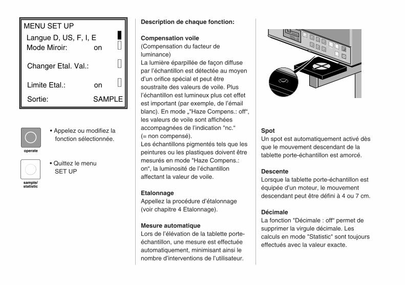
BYK
GardenerVersion: 2.6Copyright 1990
haze
20°
60°
85°
20° + 60°auto-range
60° + 85°
sample/statistic results
delete
set up
operate
sample/statistic
• Appelez ou modifiez la fonction sélectionnée.
• Quittez le menu SET UP
SpotUn spot est automatiquement activé dèsque le mouvement descendant de latablette porte-échantillon est amorcé.
DescenteLorsque la tablette porte-échantillon estéquipée d’un moteur, le mouvementdescendant peut être défini à 4 ou 7 cm.
DécimaleLa fonction "Décimale : off“ permet desupprimer la virgule décimale. Lescalculs en mode "Statistic" sont toujourseffectués avec la valeur exacte.
Description de chaque fonction:
Compensation voile(Compensation du facteur deluminance)La lumière éparpillée de façon diffusepar l’échantillon est détectée au moyend’un orifice spécial et peut êtresoustraite des valeurs de voile. Plusl’échantillon est lumineux plus cet effetest important (par exemple, de l’émailblanc). En mode „"Haze Compens.: off“,les valeurs de voile sont affichéesaccompagnées de l’indication "nc.“(= non compensé).Les échantillons pigmentés tels que lespeintures ou les plastiques doivent êtremesurés en mode "Haze Compens.:on“, la luminosité de l’échantillonaffectant la valeur de voile.
EtalonnageAppellez la procédure d’étalonnage(voir chapitre 4 Etalonnage).
Mesure automatiqueLors de l’élévation de la tablette porte-échantillon, une mesure est effectuéeautomatiquement, minimisant ainsi lenombre d’interventions de l’utilisateur.
operate
MENU SET UP
Langue D, US, F, I, EMode Miroir: on
Changer Etal. Val.:
Limite Etal.: on
Sortie: SAMPLE
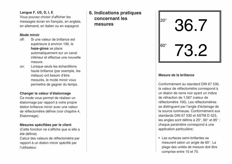
20° 36.760° 73.2
Langue F, US, D, I, EVous pouvez choisir d’afficher lesmessages écran en français, en anglais,en allemand, en italien ou en espagnol.
Mode miroiroff: Si une valeur de brillance est
supérieure à environ 190, lehaze-gloss se placeautomatiquement sur un canalinférieur et effectue une nouvellemesure.
on: Lorsque seuls les échantillonshaute brillance (par exemple, lesmétaux) ont besoin d’êtremesurés, le mode miroir vouspermettra de gagner du temps.
Changer la valeur d’étalonnageCe mode vous permet de réaliser unétalonnage par rapport à votre propreétalon brillance miroir avec une valeurde réflectomètre définie (voir chapitre 4,Etalonnage).
Mesures spécifiées par le client(Cette fonction ne s’affiche que si elle aété définie)Calcul des valeurs de réflectomètre parrapport à un étalon miroir spécifié parl’utilisateur.
6. Indications pratiques concernant les mesures
Mesure de la brillance
Conformément au standard DIN 67 530,la valeur de réflectomètre correspond àun étalon de verre noir ayant un indicede réfraction de 1,567 (valeur deréflectomètre 100). Les réflectomètresse distinguent par l’angle d’éclairage dela source lumineuse. Conformément auxstandards DIN 67 530 et ASTM D 523,les angles sont définis à 20°, 60° et 85° ;chaque paramètre correspond à uneapplication particulière:
• Les surfaces semi-brillantes semesurent selon un angle de 60°. Laplage des unités de mesure doit êtrecomprise entre 10 et 70.

Mesure de la réflexion miroir
Le haze-gloss offre une plage demesure étendue permettant de traiterdes échantillons à fort pouvoirréfléchissant (surfaces métalliquespolies, miroirs).
Dans ce mode, les plages de valeurssont les suivantes :
2000 unités à 20°1000 unités à 60° 160 unités à 85°
(étalonnage réalisé par le fabricant).
La mesure de la brillance étant souventrelative aux étalons du client,haze-gloss permet d’effectuerl’étalonnage nécessaire selon lesspécifications de ce dernier (voirchapitre 4, Etalonnage).
AUTO-RANGE60° 20.785° 47.2
Remarque
• En mode réglage automatique "auto- range" les angles utilisés sont les suivants : 60/85° pour les valeurs de réflectomètre inférieures à 30; 60° pour les valeurs de réflectomètre entre 30 et 70; 20/60° pour les valeurs de réflectomètré supérieures à 70 (les
valeurs de réflectomètre sont toujoursrelatives à un angle de 60°).
• Il est inutile d’effectuer des mesures sur des échantillons endommagés ou rayés, à moins que vous ne souhaitiez évaluer le degré de tels défauts en mesurant leur brillance.
• Lorsque des surfaces fortement réfléchissantes sont mesurées selon un angle de 60° et que la valeur mesurée est supérieure à 70 unités, la mesure doit être répétée en utilisant la géométrie à 20°.
• Les surfaces mates dont la valeur (selon un angle de 60°) est inférieure à 10 unités doit être mesurée en utilisant la géométrie à 85°.
Pour obtenir une meilleuredifférenciation des valeurs mesurées,nous recommandons la géométrie à 85°chaque fois que la valeur mesurée à60° est inférieure à 30 unités. Lesrecommandations varient selon lesstandards. Tandis que la norme ASTMD 523 fixe à 10 unités la limitesupérieure au delà de laquelle lepassage de 60° à 85° est nécessaire,ISO 2813 la fixe à 30 unités. Ces limitesdoivent être considérées comme desrecommandations.
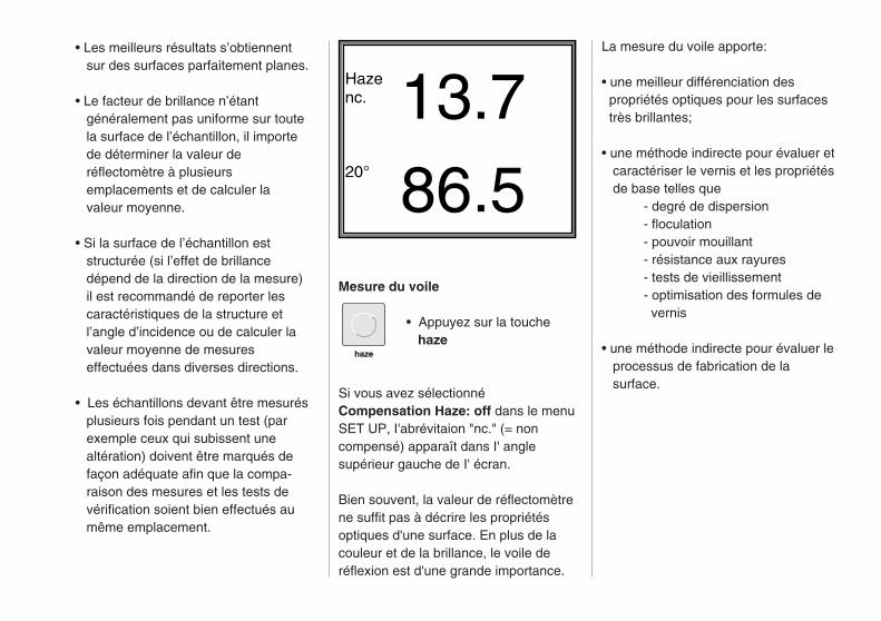
• Les meilleurs résultats s’obtiennent sur des surfaces parfaitement planes.
• Le facteur de brillance n’étant généralement pas uniforme sur toute la surface de l’échantillon, il importe de déterminer la valeur de réflectomètre à plusieurs emplacements et de calculer la valeur moyenne.
• Si la surface de l’échantillon est structurée (si l’effet de brillance dépend de la direction de la mesure) il est recommandé de reporter les caractéristiques de la structure et l’angle d’incidence ou de calculer la valeur moyenne de mesures effectuées dans diverses directions.
• Les échantillons devant être mesurés plusieurs fois pendant un test (par exemple ceux qui subissent une altération) doivent être marqués de façon adéquate afin que la compa- raison des mesures et les tests de vérification soient bien effectués au même emplacement.
La mesure du voile apporte:
• une meilleur différenciation des propriétés optiques pour les surfaces très brillantes;
• une méthode indirecte pour évaluer et caractériser le vernis et les propriétés de base telles que
- degré de dispersion- floculation- pouvoir mouillant- résistance aux rayures- tests de vieillissement- optimisation des formules de vernis
• une méthode indirecte pour évaluer le processus de fabrication de la surface.
Hazenc. 13.720° 86.5
Mesure du voile
• Appuyez sur la touche haze
Si vous avez sélectionnéCompensation Haze: off dans le menuSET UP, I'abrévitaion "nc." (= noncompensé) apparaît dans I' anglesupérieur gauche de I' écran.
Bien souvent, la valeur de réflectomètrene suffit pas à décrire les propriétésoptiques d'une surface. En plus de lacouleur et de la brillance, le voile deréflexion est d'une grande importance.
haze

20°
haze
85°
60°
20°
60°
85°a
a
b
c
Remarque
La valeur de voile de réflexion s’affichesous forme logarithmique
• de façon à se rapprocher le pluspossible de la perception du voile deréflexion par l’oeil humain;
• de façon à obtenir une plus grandesensibilité en cas de valeurs de voiletrès faibles.(Plus la valeur de voile est faible, plusla qualité de la surface est grande.)
L’équation
L’équation correspondant au voile deréflexion est la suivante :H = K x lg (valeur de voile linéaire /20 + 1)
La constante k = 1285,1 permetd’obtenir une valeur de voile logarith-mique de 1000 pour une valeur linéairede 100 unités de voile.
Pour mesurer le voile de réflexion, deuxouvertures supplémentaires c (largeur =1,8°) sont placées de part et d’autre del’ouverture de 20°, réservée à la mesurede la brillance spéculaire. Celles-cipermettent de mesurer la lumièrediffuse adjacente à l’angle spéculaire de20°.
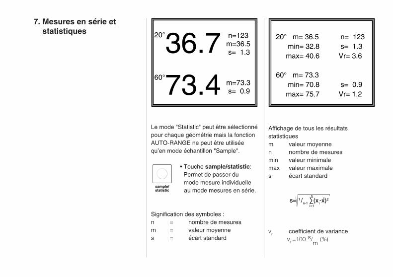
20°36.760°73.4
n=123m=36.5 s= 1.3
m=73.3 s= 0.9
20° m= 36.5 min= 32.8 max= 40.6
60° m= 73.3 min= 70.8 max= 75.7
n= 123 s= 1.3Vr= 3.6
s= 0.9Vr= 1.2
sample/statistic
Affichage de tous les résultatsstatistiquesm valeur moyennen nombre de mesuresmin valeur minimalemax valeur maximales écart standard
vr coefficient de variancevr =100 s/
m (%)
Le mode "Statistic" peut être sélectionnépour chaque géométrie mais la fonctionAUTO-RANGE ne peut être utiliséequ’en mode échantillon "Sample".
• Touche sample/statistic: Permet de passer du mode mesure individuelle au mode mesures en série.
Signification des symboles :n = nombre de mesuresm = valeur moyennes = écart standard
s= 1 /n-1 ∑(xi-x)2n
i=1
-
7. Mesures en série et statistiques

Remarque
Lors des changements de géométrie oude l’utilisation du mode SAMPLE, lesvaleurs de mesure du mode STATISTICsont sauvegardées et protégées.haze-gloss peut sauvegarder une sériede 600 mesures au maximum pargéométrie. Ces données peuvent êtretransférées sur un PC via l’interfaceRS 232.Si un changement de géométrieintervient en mode STATISTIC, lesvaleur de la dernière série de mesuressont affichées et la série peut sepoursuivre si nécessaire.Pendant l’exécution d’une série demesures en mode STATISTIC,l’étalonnage ne doit pas être modifié(compensation, brillance miroir,spécifications client) afin de ne pasfausser les résultats statistiques.
delete
results
8. Spécifications internationales
EFFACER
Effacer statistique -->RESULTS
Sortie:
SAMPLE
• Touche delete supprime la dernière lecture.
La variable de comptage est réduited’une unité. La dernière lecture ne peutêtre supprimée que si aucune autrefonction n’a été invoquée après ladernière mesure.
• Touche results supprime toute la série de mesures correspondant à la géométrie définie.

DIN 67 530Réflectomètre comme moyend’évaluation de la brillance des surfacesplanes (couches de peinture et matièresplastiques).
ISO 2813Peinture et vernis -Mesure de la brillance spéculaire descouches de peinture non métallique à20°, 60° et 85°.
ANS/ASTM D 523Méthode standard de test de brillancespéculaire.
ASTM D 2457Méthode standard de test de brillancespéculaire des films plastique.
BS 3900 (Parties D2 - D5)Méthodes standard britanniques de testde brillance des peintures (Valeur deréflexion spéculaire).
JIS Z 8741Méthode de mesure de la brillancespéculaire.
Le haze-gloss est équipé d’une interfacesérie (RS 232 C) permettant demanipuler et de contrôler les données demesure à partir d’un PC. Un connecteurSUB-D à 9 broches est monté surl’instrument à des fins de transfert.
haze-gloss PC3 TxD —— RxD 32 RxD —— TxD 27 RTS —— CTS 58 CTS —— RTS 45 — GRND —— 7
Taux de transfert et format
Le transfert série des données en modeasynchrone est spécifié dans l’instrumentde mesure et exécuté selon le formatsuivant:
2400 bauds, 8 bits de données, sansparité, 1 bit de fin.
Commandes de contrôle
"O“ (ASCII) permet de démarrer lesopérations en ligne (le message ON-LINE s’affiche à l’écran).- le clavier du haze-gloss est bloqué- les mesures automatiques s’exécutent une fois le commutateur d’exécution activé.
9. Description de l’interface
1 6
59
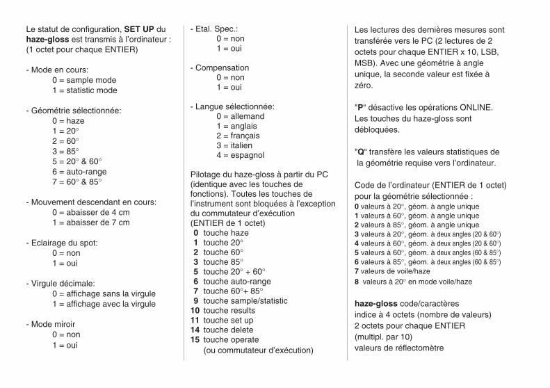
Le statut de configuration, SET UP duhaze-gloss est transmis à l’ordinateur :(1 octet pour chaque ENTIER)
- Mode en cours:0 = sample mode1 = statistic mode
- Géométrie sélectionnée:0 = haze1 = 20°2 = 60°3 = 85°5 = 20° & 60°6 = auto-range7 = 60° & 85°
- Mouvement descendant en cours:0 = abaisser de 4 cm1 = abaisser de 7 cm
- Eclairage du spot:0 = non1 = oui
- Virgule décimale:0 = affichage sans la virgule1 = affichage avec la virgule
- Mode miroir0 = non1 = oui
- Etal. Spec.:0 = non1 = oui
- Compensation0 = non1 = oui
- Langue sélectionnée:0 = allemand1 = anglais2 = français3 = italien4 = espagnol
Pilotage du haze-gloss à partir du PC(identique avec les touches defonctions). Toutes les touches del’instrument sont bloquées à l’exceptiondu commutateur d’exécution(ENTIER de 1 octet)0 touche haze1 touche 20°2 touche 60°3 touche 85°5 touche 20° + 60°6 touche auto-range7 touche 60°+ 85°9 touche sample/statistic
10 touche results11 touche set up14 touche delete15 touche operate
(ou commutateur d’exécution)
Les lectures des dernières mesures sonttransférée vers le PC (2 lectures de 2octets pour chaque ENTIER x 10, LSB,MSB). Avec une géométrie à angleunique, la seconde valeur est fixée àzéro.
"P“ désactive les opérations ONLINE.Les touches du haze-gloss sontdébloquées.
"Q“ transfère les valeurs statistiques de la géométrie requise vers l’ordinateur.
Code de l’ordinateur (ENTIER de 1 octet)pour la géométrie sélectionnée :0 valeurs à 20°, géom. à angle unique1 valeurs à 60°, géom. à angle unique2 valeurs à 85°, géom. à angle unique3 valeurs à 20°, géom. à deux angles (20 & 60°)4 valeurs à 60°, géom. à deux angles (20 & 60°)5 valeurs à 60°, géom. à deux angles (60 & 85°)6 valeurs à 85°, géom. à deux angles (60 & 85°)7 valeurs de voile/haze8 valeurs à 20° en mode voile/haze
haze-gloss code/caractèresindice à 4 octets (nombre de valeurs)2 octets pour chaque ENTIER(multipl. par 10)valeurs de réflectomètre
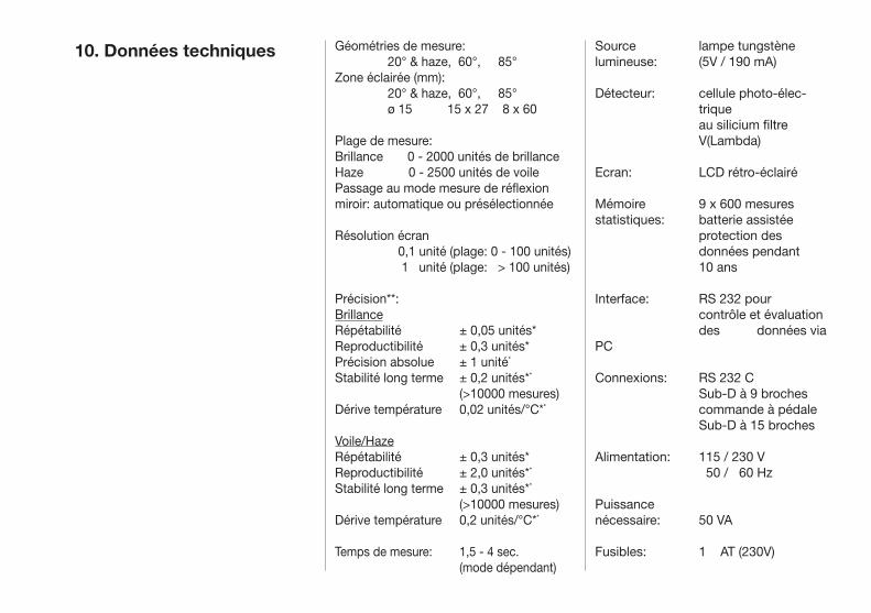
Source lampe tungstènelumineuse: (5V / 190 mA)
Détecteur: cellule photo-élec- trique au silicium filtre V(Lambda)
Ecran: LCD rétro-éclairé
Mémoire 9 x 600 mesuresstatistiques: batterie assistée protection des données pendant 10 ans
Interface: RS 232 pour contrôle et évaluation des données via PC
Connexions: RS 232 C Sub-D à 9 broches commande à pédale Sub-D à 15 broches
Alimentation: 115 / 230 V 50 / 60 Hz
Puissance nécessaire: 50 VA
Fusibles: 1 AT (230V)
10. Données techniques Géométries de mesure: 20° & haze, 60°, 85°Zone éclairée (mm): 20° & haze, 60°, 85° ø 15 15 x 27 8 x 60
Plage de mesure:Brillance 0 - 2000 unités de brillanceHaze 0 - 2500 unités de voilePassage au mode mesure de réflexion miroir: automatique ou présélectionnée
Résolution écran 0,1 unité (plage: 0 - 100 unités) 1 unité (plage: > 100 unités)
Précision**:BrillanceRépétabilité ± 0,05 unités*Reproductibilité ± 0,3 unités*Précision absolue ± 1 unité* Stabilité long terme ± 0,2 unités**
(>10000 mesures)Dérive température 0,02 unités/°C**
Voile/HazeRépétabilité ± 0,3 unités* Reproductibilité ± 2,0 unités** Stabilité long terme ± 0,3 unités**
(>10000 mesures)Dérive température 0,2 unités/°C**
Temps de mesure: 1,5 - 4 sec. (mode dépendant)
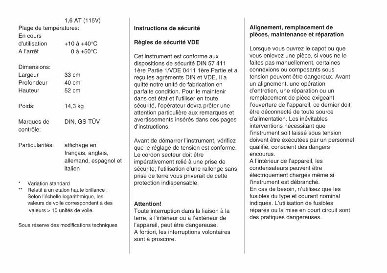
1,6 AT (115V)Plage de températures:En coursd'utilisation +10 à +40°CA l’arrêt 0 à +50°C
Dimensions:Largeur 33 cmProfondeur 40 cmHauteur 52 cm
Poids: 14,3 kg
Marques de DIN, GS-TÜVcontrôle:
Particularités: affichage enfrançais, anglais,allemand, espagnol etitalien
* Variation standard** Relatif à un étalon haute brillance ;
Selon l’échelle logarithmique, lesvaleurs de voile correspondent à des valeurs > 10 unités de voile.
Sous réserve des modifications techniques
Instructions de sécurité
Règles de sécurité VDE
Cet instrument est conforme auxdispositions de sécurité DIN 57 4111ère Partie 1/VDE 0411 1ère Partie et areçu les agréments DIN et VDE. Il aquitté notre unité de fabrication enparfaite condition. Pour le maintenirdans cet état et l’utiliser en toutesécurité, l’opérateur devra prêter uneattention particulière aux remarques etavertissements insérés dans ces pagesd’instructions.
Avant de démarrer l’instrument, vérifiezque le réglage de tension est conforme.Le cordon secteur doit êtreimpérativement relié à une prise desécurite; l’utilisation d’une rallonge sansprise de terre vous priverait de cetteprotection indispensable.
Attention!Toute interruption dans la liaison à laterre, à l’intérieur ou à l’extérieur del’appareil, peut être dangereuse.A fortiori, les interruptions volontairessont à proscrire.
Alignement, remplacement depièces, maintenance et réparation
Lorsque vous ouvrez le capot ou quevous enlevez une pièce, si vous ne lefaites pas manuellement, certainesconnexions ou composants soustension peuvent être dangereux. Avantun alignement, une opérationd’entretien, une réparation ou unremplacement de pièce exigeantl’ouverture de l’appareil, ce dernier doitêtre déconnecté de toute sourced’alimentation. Les inévitablesinterventions nécessitant quel’instrument soit laissé sous tensiondoivent être exécutées par un personnelqualifié, conscient des dangersencourus.A l’intérieur de l’appareil, lescondensateurs peuvent êtreélectriquement chargés même sil’instrument est débranché.En cas de besoin, n’utilisez que lesfusibles du type et courant nominalindiqués. L’utilisation de fusiblesréparés ou la mise en court circuit sontdes pratiques dangereuses.
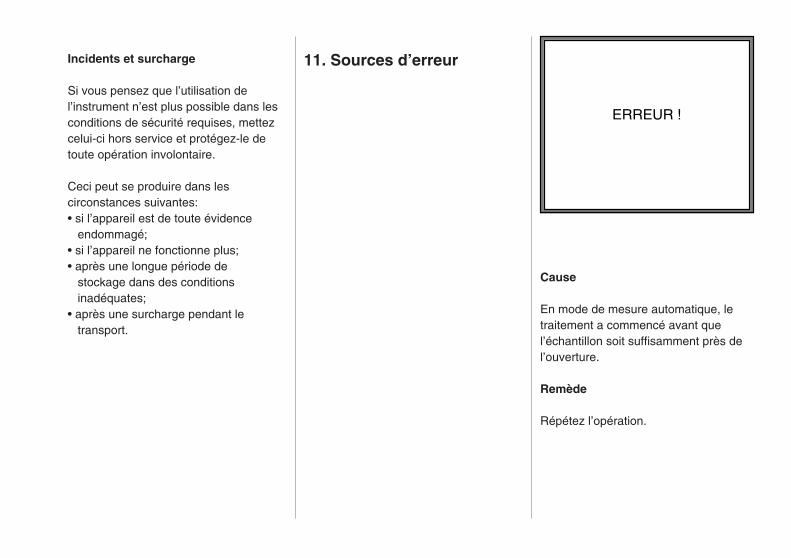
Incidents et surcharge
Si vous pensez que l’utilisation del’instrument n’est plus possible dans lesconditions de sécurité requises, mettezcelui-ci hors service et protégez-le detoute opération involontaire.
Ceci peut se produire dans lescirconstances suivantes:• si l’appareil est de toute évidence endommagé;• si l’appareil ne fonctionne plus;• après une longue période de stockage dans des conditions inadéquates;• après une surcharge pendant le transport.
11. Sources d’erreur
ERREUR !
Cause
En mode de mesure automatique, letraitement a commencé avant quel’échantillon soit suffisamment près del’ouverture.
Remède
Répétez l’opération.
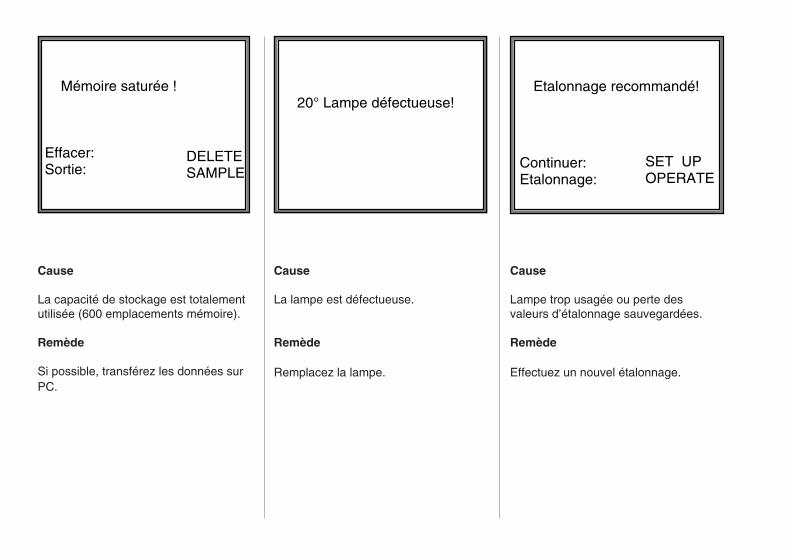
Etalonnage recommandé!
SET UPOPERATE
Continuer:Etalonnage:
Mémoire saturée !
Effacer:Sortie:
DELETESAMPLE
20° Lampe défectueuse!
Cause
La capacité de stockage est totalementutilisée (600 emplacements mémoire).
Remède
Si possible, transférez les données surPC.
Cause
La lampe est défectueuse.
Remède
Remplacez la lampe.
Cause
Lampe trop usagée ou perte desvaleurs d’étalonnage sauvegardées.
Remède
Effectuez un nouvel étalonnage.

N° Ref AG-4613Câble de connexion PC (SUB-D à 25 broches)
N° Ref AG-4614Etalon haut-brillant
N° Ref AG-4615Etalon de voile de réflexion
N° Ref AG-4616Etalon semi-brillant supplémentaire, 20°
N° Ref AG-4617Etalon semi-brillant supplémentaire, 30°
N° Ref AG-4618Etalon semi-brillant supplémentaire, 85°
N° Ref AG-4623Plate-forme plus grande pour tabletteporte-échantillon (280 x 150 cm)
N° Ref AG-4545BYKWARE easy-link
N° Ref AG-4056Etalon brillance miroir
Pour ce qui concerne la garantie, reportez-vous aux Conditions de Vente Standard BYK-Gardner.
Composants de la version de base
haze-gloss avec moteur N° Ref AG-4601- Instrument de mesure- Commande à pédale- Etalon haute-brillance- Etalon haze- Cordon d’alimentation- Instructions d’utilisation, tissu de nettoyage
12. Liste des composants et accessoires

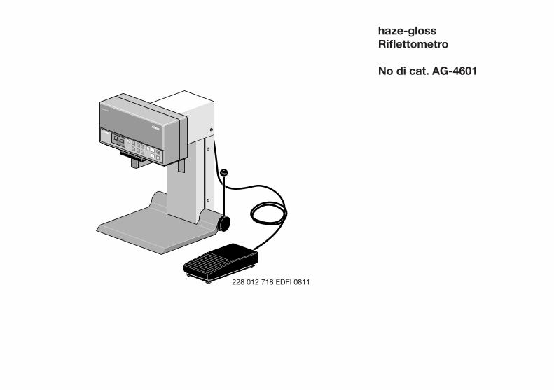
haze-glossRiflettometro
No di cat. AG-4601
Gardner
haze-gloss
GardenerVersion: 2.6Copyright 1990
Gesamtansicht
228 012 718 EDFI 0811


Gardner
haze-gloss
GardenerVersion: 2.6Copyright 1990
Gesamtansicht
haze-glossRiflettometro
No di cat. AG-4601
Indice
1. Descrizione dell' impianto 2. Avvio 3. Funzionamento 4. Calibrazione 5. Selezione dei parametri dello strumento Menù Avvio 6. Suggerimenti per misurazione speciale 7. Misurazioni in serie o statistiche 8. Specifiche internazionali 9. Descrizione interfaccia 10. Dati tecnici 11. Fonti di errori 12. Lista componenti e accessori 13. Indirizzi dei fornitori
I dati tecnici possono subire modifiche.

Gardner
haze-gloss
BYK
GardenerVersion: 2.6Copyright 1990
Gesamtansicht
Interruttore di accensioneSelettore voltaggio di reteFusibili
Connessioni per RS 232Comando a pedaleCavo alimentazione
Pannello comandiDisplay LCD
Tavola supporto campione
Leva per abbassamento manuale del supporto campione
Comando a pedale per abbassamento motorizzato del supporto campione
1. Descrizione Impianto Il riflettometro haze-gloss è uno stru-mento fisso idearo per la misurazione del gloss speculare e dell' haze in rifles-sione su rivestimenti in vernici, plastica, leganti, pigmenti e superfici metalliche (mirror reflection).
La superficie del campione è illuminata ad un angolo ben definito e la luce dif-fusa è misurata fotoelettricamente. La selezione dell' angolo di illuminazione appropriato (geometria) dipende dal livello specifico del gloss della superfi-cie del campione: opaco, medio o alto gloss. (Per la scelta dell' appropriato range di misura, vedere Capitolo 6, Suggerimenti pratici di misurazione.)
L' ingegneria elettronica avanzata nello sviluppo e nella produzione dell' haze-gloss, fornisce prestazione, facil-ità di operazione ed elevata precisione ad un livello mai prima raggiunto.
• Tre geometrie: 20o, 60o & 85o
Riflessione su superfici metalliche, Haze in riflessione
• Il supporto campione permette un rapido cambio dei campioni e può essere motorizzato e controllato da un comando a pedale
• Bersaglio illuminato per posiziona-
mento accurato del campione
• Pannello di controllo a lettura facilitata ed operazione controllata da microprocessori
• Alta precisione e stabilità a lungo termine dovuti al principio del raggio di riferimento
• Nessun tempo di pre-riscaldamento, funzionamento immediato, calibrazio- ne a lungo termine (≥ogni 2 mesi)
• Capacità di valutazione statistiche e memorizzazione
• Interfaccia per trasferimento dati e controllo tramite PC
• Il display può essere selezionato in Inglese, Tedesco, Francese, Spagnolo o Italiano
L' unità di misura dello strumento haze-gloss è conforme agli standards ISO 2813, ASTM D 523 e DIN 67530.
2. Avvio Avvertenze
Si prega leggere le istruzioni prima di mettere in funzione I'apparecchio. Il sistema haze-gloss non richiede una stanza speciale per la misurazione. Come con tutti gli apparecchi elettron-ici, comunque, è importante seguire le solite condizioni di funzionamento.
Si prega di evitare:
• eccessive oscillazioni e vibrazioni
• temperature ambiente estreme
• shocks di temperatura
• umidità dell' aria ≥ 85% • prodotti chimici caustici ed esplosivi, vapori aggressivi, e gas
• campi elettromagnetici estremi
• scario elettrostatico estremo
• penetrazioni di materiale estraneo nell'apertura di misurazione
L' involucro dello strumento è resistente ad un certo numero di solventi. Co-munque, non può essere assicurata la resistenza a tutti i prodotti chimici. Per questa ragione, si prega di usare un panno morbido e umido quando lo si pulisce. In caso di grave contami-nazione può essere usato dell'alcool o schiuma di sapone. Se il Vostro haze-gloss dovesse presentare un malfunzionamento, Vi chiediamo di non cercare di riparare I' apparecchio Voi stessi. Il nostro servizio clienti sarà lieto di aiutarVi il più veloce-mente possibile.

Anschlüsse
TYP
CAT.-NR.
F-NR.
4601
9017571
110/220 V 50/60 HZ 250 VAUSE ONLY W
ITH 250 VFUSES / EMPLOYERUNIQUEMENT AVEC
DES FUIBLES WITH 250 V
110-120 V
220-
240
V
haze-gloss
Verpackung mit Person
Installazione
Bisogna sempre disinserie lo strumento dalla rete elettrica prima di innestare o disinnestare i vari connettori!
Togliere lo strumento dalla scatola e controllare ogni possibilità di danno durante la spedizione (ispezione visiva.) Prima dell'operazione iniziale, control-lare che la spedizione sia completa (per i componenti vedere il capitolo 12, lista componenti ed accessori).
Installare il modulo nel suo luogo di destinazione.
Interfaccia RS 232
Comando a pedale
Fusibili selettore voltaggio
Innesto per cavo alimentazione
Interruttore di accensione
Controllare la posizione del selettore del voltaggio sul pannello posteriore e, se necessario, posizionare il selettore sul Vostro voltaggio di rete com segue: Rimuovere il coperchio di plastica vicino al connettore del cavo di ali-mentazione. Poi innestare il coperchio di plastica in modo che il segno trian-golare sul contenitore dell' interruttore e I' indicazione della corrente richiesta coinicidano.
Con il modulo ancora disconnesso, innestare il filo nella presa di corrente.
Nel caso di sistema motorizzato: col-legare I' interruttore a pedale.
Se richiesto, inserire il cavo di connes-sione al PC nella presa RS 232.
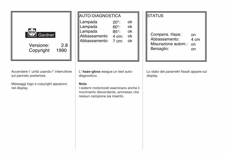
Accendere I' unità usando I' interruttore sul pannelo posteriore.
Messaggi logo e copyright appaiono nel display.
L' haze-gloss esegue un test auto-diagnostico.
NotaI sistemi motorizzati esaminano anche il movimento discendente, ammesso che nessun campione sia inserito.
Lo stato dei parametri fissati appare sul display.
Versione: 2.8Copyright 1990
Gardner
AUTO-DIAGNOSTICALampadaLampadaLampadaAbbassamentoAbbassamento
20°:60°:85°:4 cm:7 cm:
okokokokok
STATUS
Compens. Haze:Abbassamento:Misurazione autom.:Bersaglio:
on4 cmonon
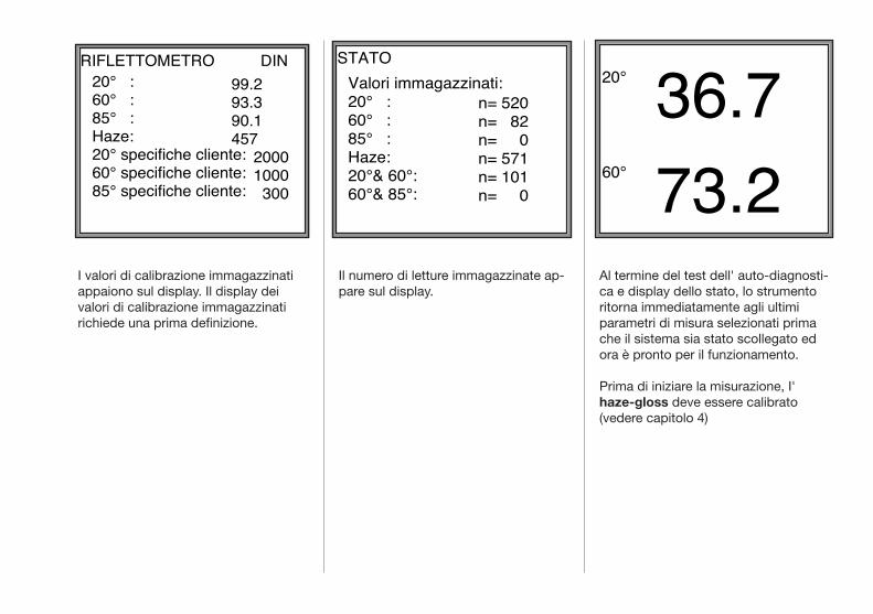
I valori di calibrazione immagazzinati appaiono sul display. Il display dei valori di calibrazione immagazzinati richiede una prima definizione.
Il numero di letture immagazzinate ap-pare sul display.
Al termine del test dell' auto-diagnosti-ca e display dello stato, lo strumento ritorna immediatamente agli ultimi parametri di misura selezionati prima che il sistema sia stato scollegato ed ora è pronto per il funzionamento.
Prima di iniziare la misurazione, I' haze-gloss deve essere calibrato (vedere capitolo 4)
20° 36.760° 73.2
RIFLETTOMETRO20° :60° :85° :Haze:20° specifiche cliente:60° specifiche cliente:85° specifiche cliente:
99.293.390.1457 2000 1000 300
DIN STATOValori immagazzinati:20° :60° :85° :Haze:20°& 60°:60°& 85°:
n= 520n= 82n= 0n= 571n= 101n= 0

haze 20° 60° 85°
20° + 60° auto-range 60° + 85°
sample/statistic
results
delete
set up
operate
3. Funzionamento
Rilasciare rispettivamente la leva manuale o I' accensione a pedale.Ora la tavola supporto muove il campione verso I' apertura di misurazione.
La misurazione è avviata automatica-mente ma può anche essere avviata manualmente premendo il tasto di operazione. (vedere Menù SET UP : Misurazione automatica).
I valori misurati e la corrispondente geometria di misurazione, appaiono sul display.
Selezionare la geometria desiderata o la funzione auto-regolazione (vedere il capitolo 6, suggerimenti pratici di misurazione).
Abbassare la tavola di supporto campi-one usando la leva manuale, o coman-do a pedale nel caso di un supporto campione motorizzato.
Inserire il campione con la superficie di prova orientata verso I'alto. Controllare il campione per possibili difetti di superficie (ad es. graffi, im-pronte). L'area illuminata indica il punto sul quale sarà effettuata la misurazione del campione (vedere il menù SET UP: Bersaglio).
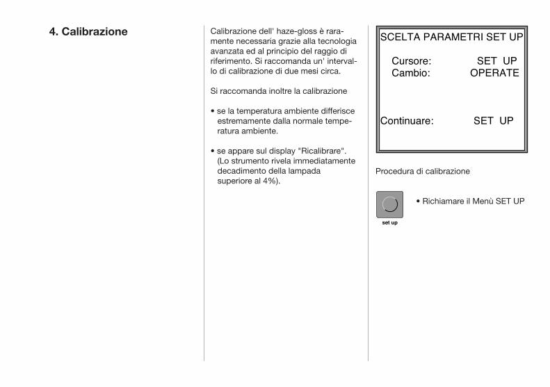
set up
4. Calibrazione Calibrazione dell' haze-gloss è rara-mente necessaria grazie alla tecnologia avanzata ed al principio del raggio di riferimento. Si raccomanda un' interval-lo di calibrazione di due mesi circa.
Si raccomanda inoltre la calibrazione
• se la temperatura ambiente differisce estremamente dalla normale tempe- ratura ambiente.
• se appare sul display "Ricalibrare". (Lo strumento rivela immediatamente decadimento della lampada superiore al 4%).
Procedura di calibrazione
• Richiamare il Menù SET UP
set up
SCELTA PARAMETRI SET UP Cursore: SET UP Cambio: OPERATE
Continuare: SET UP
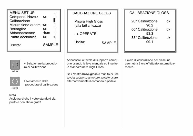
• Selezionare la procedu- ra di calibrazione
• Avviamento della procedura di calibrazione
NotaAssicurarsi che il vetro standard sia pulito e non abbia graffi!
operate
set up
Il ciclo di calibrazione per ciascuna geometria è ora effettuato automatica-mente.
Abbassare la tavola di supporto campi-one usando la leva manuale ed inserire lo standard nero High-Gloss.
Se il Vostro haze-gloss é munito di una tavola supporto a motore, potete usare alternativamente il comando a pedale.
CALIBRAZIONE GLOSS Misura High Gloss
(alta brillantezza)
--> OPERATE
Uscita:
SAMPLE
CALIBRAZIONE GLOSS 20° Calibrazione ok 90.2
60° Calibrazione ok 93.3
85° Calibrazione ok 99.1
MENU SET UP Compens. Haze.: CalibrazioneMisurazione autom.: Bersaglio:Abbassamento:Punto decimale:
Uscita:
on
onon4cmon
SAMPLE
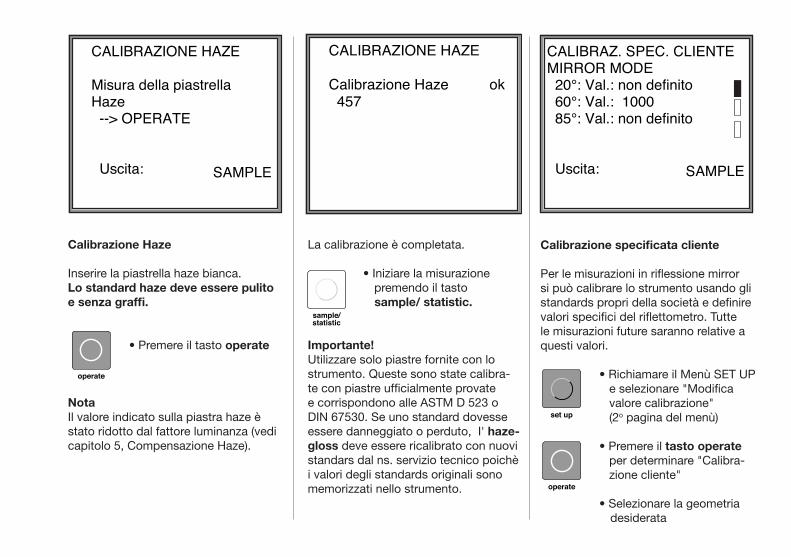
Calibrazione Haze
Inserire la piastrella haze bianca.Lo standard haze deve essere pulito e senza graffi.
• Premere il tasto operate
NotaIl valore indicato sulla piastra haze è stato ridotto dal fattore luminanza (vedi capitolo 5, Compensazione Haze).
Calibrazione specificata cliente
Per le misurazioni in riflessione mirror si può calibrare lo strumento usando gli standards propri della società e definire valori specifici del riflettometro. Tutte le misurazioni future saranno relative a questi valori.
• Richiamare il Menù SET UP e selezionare "Modifica valore calibrazione" (2o pagina del menù)
• Premere il tasto operate per determinare "Calibra- zione cliente"
• Selezionare la geometria desiderata
operate
sample/statistic
set up
operate
La calibrazione è completata.
• Iniziare la misurazione premendo il tasto sample/ statistic.
Importante!Utilizzare solo piastre fornite con lo strumento. Queste sono state calibra-te con piastre ufficialmente provate e corrispondono alle ASTM D 523 o DIN 67530. Se uno standard dovesse essere danneggiato o perduto, I' haze-gloss deve essere ricalibrato con nuovi standars dal ns. servizio tecnico poichè i valori degli standards originali sono memorizzati nello strumento.
CALIBRAZIONE HAZE Misura della piastrellaHaze --> OPERATE
Uscita:
SAMPLE
CALIBRAZIONE HAZE Calibrazione Haze ok 457
CALIBRAZ. SPEC. CLIENTEMIRROR MODE 20°: Val.: non definito 60°: Val.: 1000 85°: Val.: non definito
Uscita:
SAMPLE
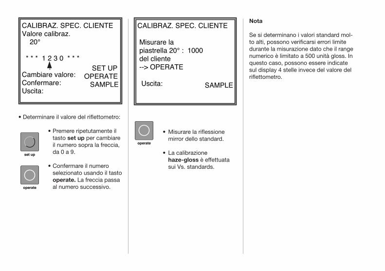
set up
operate
operate
• Determinare il valore del riflettometro:
• Premere ripetutamente il tasto set up per cambiare il numero sopra la freccia, da 0 a 9.
• Confermare il numero selezionato usando il tasto operate. La freccia passa al numero successivo.
Nota
Se si determinano i valori standard mol-to alti, possono verificarsi errori limite durante la misurazione dato che il range numerico è limitato a 500 unità gloss. In questo caso, possono essere indicate sul display 4 stelle invece del valore del riflettometro.
• Misurare la riflessione mirror dello standard.
• La calibrazione haze-gloss è effettuata sui Vs. standards.
CALIBRAZ. SPEC. CLIENTEValore calibraz. 20° * * * 1 2 3 0 * * * Cambiare valore: Confermare:Uscita:
SET UPOPERATE SAMPLE
CALIBRAZ. SPEC. CLIENTE
Misurare la piastrella 20° : 1000 del cliente --> OPERATE
Uscita:
SAMPLE
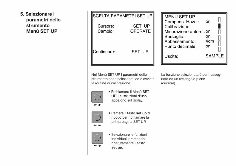
set up
set up
set up
5. Selezionare i parametri dello strumento Menù SET UP
Nel Menù SET UP i parametri dello strumento sono selezionati ed è avviata la routine di calibrazione.
• Richiamare il Menù SET UP. Le istruzioni d'uso appaiono sul diplay.
• Pemere il tasto set up di nuovo per richiamare la prima pagina SET UP.
• Selezionare le funzioni individuali premendo ripetutamente il tasto set up.
La funzione selezionata è contrasseg-nata da un rettangolo pieno (cursore).
SCELTA PARAMETRI SET UP Cursore: SET UP Cambio: OPERATE
Continuare: SET UP
MENU SET UP Compens. Haze.: CalibrazioneMisurazione autom.: Bersaglio:Abbassamento:Punto decimale:
Uscita:
on
onon4cmon
SAMPLE
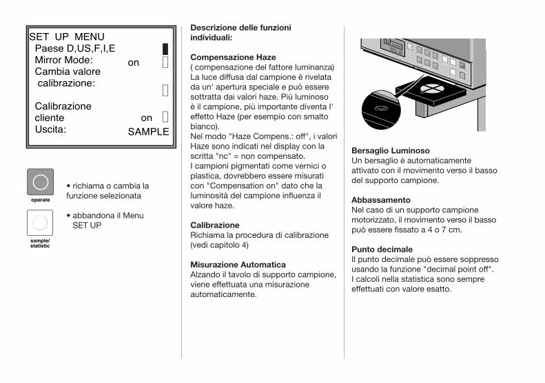
Ausschnitt Sensor
BYK
GardenerVersion: 2.6Copyright 1990
haze
20°
60°
85°
20° + 60°auto-range
60° + 85°
sample/statistic results
delete
set up
operate
operate
sample/statistic
Bersaglio LuminosoUn bersaglio è automaticamente attivato con il movimento verso il basso del supporto campione.
AbbassamentoNel caso di un supporto campione motorizzato, il movimento verso il basso può essere fissato a 4 o 7 cm.
Punto decimaleIl punto decimale può essere soppresso usando la funzione "decimal point off". I calcoli nella statistica sono sempre effettuati con valore esatto.
Descrizione delle funzioni individuali:
Compensazione Haze ( compensazione del fattore luminanza)La luce diffusa dal campione è rivelata da un' apertura speciale e può essere sottratta dai valori haze. Più luminoso è il campione, più importante diventa I' effetto Haze (per esempio con smalto bianco). Nel modo "Haze Compens.: off", i valori Haze sono indicati nel display con la scritta "nc" = non compensato.I campioni pigmentati come vernici o plastica, dovrebbero essere misurati con "Compensation on" dato che la luminosità del campione influenza il valore haze.
CalibrazioneRichiama la procedura di calibrazione(vedi capitolo 4)
Misurazione AutomaticaAlzando il tavolo di supporto campione, viene effettuata una misurazione automaticamente.
• richiama o cambia la funzione selezionata
• abbandona il Menu SET UP
SET UP MENU Paese D,US,F,I,E Mirror Mode: Cambia valore
calibrazione: Calibrazione cliente on Uscita:
on
SAMPLE
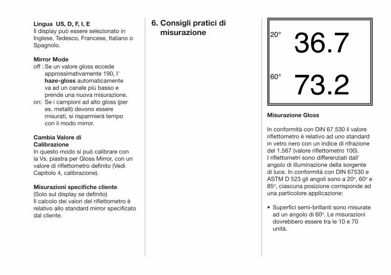
6. Consigli pratici di misurazione
Lingua US, D, F, I, EIl display può essere selezionato in Inglese, Tedesco, Francese, Italiano o Spagnolo.
Mirror Modeoff : Se un valore gloss eccede approssimativamente 190, I' haze-gloss automaticamente va ad un canale più basso e prende una nuova misurazione. on: Se i campioni ad alto gloss (per es. metalli) devono essere misurati, si risparmierà tempo con il modo mirror.
Cambia Valore di CalibrazioneIn questo modo si può calibrare con la Vs. piastra per Gloss Mirror, con un valore di riflettometro definito (Vedi Capitolo 4, calibrazione).
Misurazioni specifiche cliente(Solo sul display se definito)Il calcolo dei valori del riflettometro è relativo allo standard mirror specificato dal cliente.
Misurazione Gloss
In conformità con DIN 67 530 il valore riflettometro è relativo ad uno standard in vetro nero con un indice di rifrazione del 1.567 (valore riflettometro 100). I riflettometri sono differenziati dall' angolo di illuminazione della sorgente di luce. In conformità con DIN 67530 e ASTM D 523 gli angoli sono a 20o, 60o e 85o, ciascuna posizione corrisponde ad una particolore applicazione:
• Superfici semi-brillanti sono misurate ad un angolo di 60o. Le misurazioni dovrebbero essere tra le 10 e 70 unità.
20° 36.760° 73.2
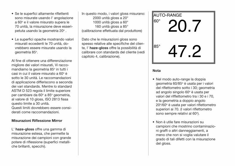
• Se le superfici altamente riflettenti sono misurate usando I' angolazione a 60o e il valore misurato supera le 70 unità, la misurazione deve esseri- petuta usando la geometria 20o .
• Le superfici opache mostrando valori misurati eccedenti le 70 unità, do- vrebbero essere misurate usando la geometria 85o.
Al fine di ottenere una differenziazione migliore dei valori misurati, Vi racco-mandiamo la geometria 85o in tutti i casi in cui il valore misurato a 60o è sotto le 30 unità. Le raccomandazioni di applicazione differiscono a seconda dei vari standards. Mentre lo standard ASTM D 523 regola il limite superiore per cambiare da 60o a 85o geometria, al valore di 10 gloss, ISO 2813 fissa questo limite a 30 unità.Questi limiti dovrebbero essere consi-derati come raccomandazioni.
Misurazioni Riflessione Mirror
L' haze-gloss offre una gamma di misurazione estesa, che permette la misurazione dei campioni con grande potere di riflessione (superfici metalli-che brillanti, specchi).
In questo modo, i valori gloss misurano: 2000 unità gloss a 20° 1000 unità gloss a 60° 160 unità gloss a 85°(calibrazione effettuata dal produttore)
Dato che le misurazioni gloss sono spesso relative alle specifiche del clien-te, I' haze-gloss offre la possibilità di calibrare con standards del cliente (vedi capitolo 4, calibrazione).
Nota
• Nel modo auto-range la doppia geometria 60/85o è usata per i valori del riflettometro sotto i 30; geometria ad angolo singolo 60o è usata per valori del rifflettometro tra i 30 e i 70, e la geometria a doppio angolo 20o/60o è usata per valori riflettometro superiori ai 70. (I valori riflettometro sono sempre relativi al 60o).
• Non è utile fare misurazioni su campioni che mostrino contaminazio-ni graffi o altri danneggiamenti, a meno che non si voglia valutare il grado di tali difetti con la misurazione del gloss.
AUTO-RANGE60° 20.785° 47.2
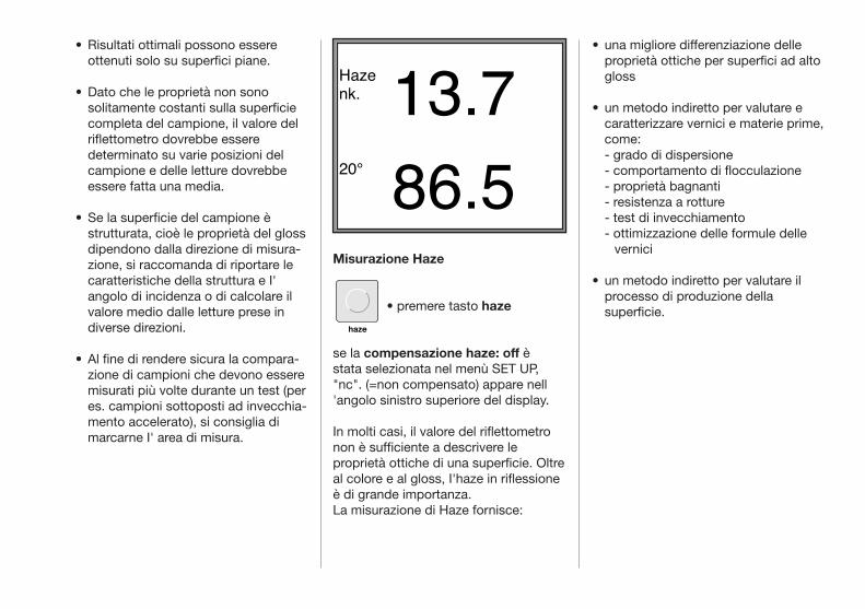
haze
• Risultati ottimali possono essere ottenuti solo su superfici piane.
• Dato che le proprietà non sono solitamente costanti sulla superficie completa del campione, il valore del riflettometro dovrebbe essere determinato su varie posizioni del campione e delle letture dovrebbe essere fatta una media.
• Se la superficie del campione è strutturata, cioè le proprietà del gloss dipendono dalla direzione di misura-zione, si raccomanda di riportare le caratteristiche della struttura e I' angolo di incidenza o di calcolare il valore medio dalle letture prese in diverse direzioni.
• Al fine di rendere sicura la compara-zione di campioni che devono essere misurati più volte durante un test (per es. campioni sottoposti ad invecchia-mento accelerato), si consiglia di marcarne I' area di misura.
• una migliore differenziazione delle proprietà ottiche per superfici ad alto gloss
• un metodo indiretto per valutare e caratterizzare vernici e materie prime, come: - grado di dispersione - comportamento di flocculazione - proprietà bagnanti - resistenza a rotture - test di invecchiamento - ottimizzazione delle formule delle vernici
• un metodo indiretto per valutare il processo di produzione della superficie.
Misurazione Haze
• premere tasto haze
se la compensazione haze: off è stata selezionata nel menù SET UP, "nc". (=non compensato) appare nell 'angolo sinistro superiore del display. In molti casi, il valore del riflettometro non è sufficiente a descrivere le proprietà ottiche di una superficie. Oltre al colore e al gloss, I'haze in riflessione è di grande importanza.La misurazione di Haze fornisce:
Hazenk. 13.720° 86.5
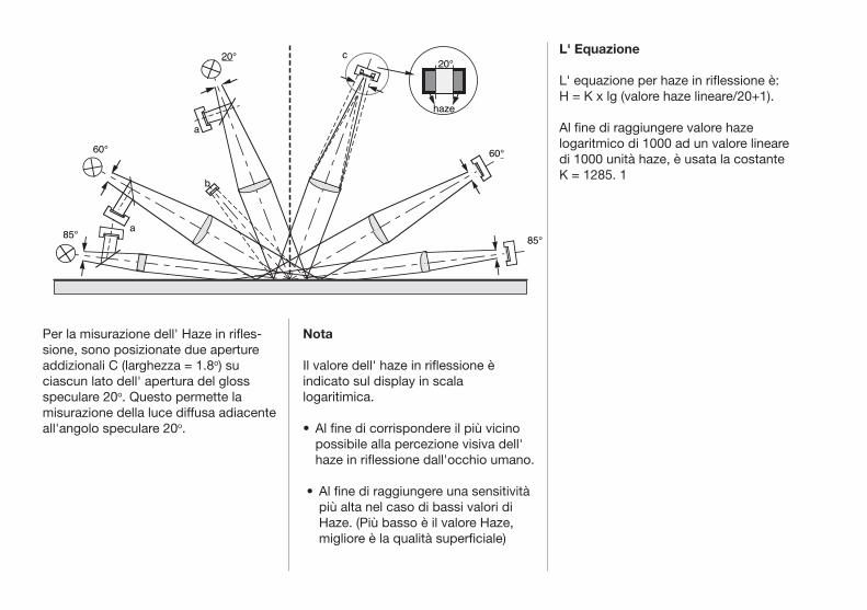
L' Equazione
L' equazione per haze in riflessione è:H = K x lg (valore haze lineare/20+1).
Al fine di raggiungere valore haze logaritmico di 1000 ad un valore lineare di 1000 unità haze, è usata la costante K = 1285. 1
Nota
Il valore dell' haze in riflessione è indicato sul display in scala logaritimica.
• Al fine di corrispondere il più vicino possibile alla percezione visiva dell' haze in riflessione dall'occhio umano.
• Al fine di raggiungere una sensitività più alta nel caso di bassi valori di Haze. (Più basso è il valore Haze, migliore è la qualità superficiale)
Per la misurazione dell' Haze in rifles-sione, sono posizionate due aperture addizionali C (larghezza = 1.8o) su ciascun lato dell' apertura del gloss speculare 20o. Questo permette la misurazione della luce diffusa adiacente all'angolo speculare 20o.
20°
haze
85°
60°
20°
60°
85° a
a
b
c
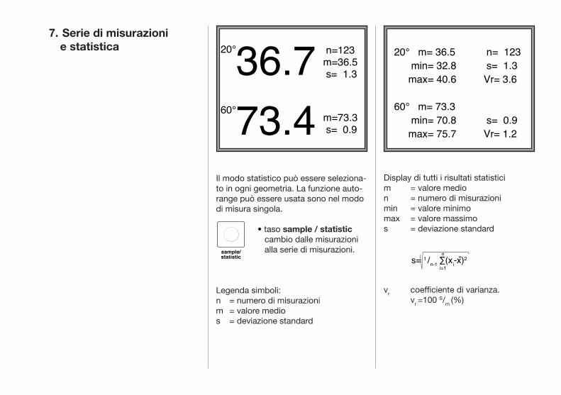
Display di tutti i risultati statisticim = valore medion = numero di misurazionimin = valore minimomax = valore massimos = deviazione standard
vr coefficiente di varianza. vr =100 S/m (%)
7. Serie di misurazioni e statistica
Il modo statistico può essere seleziona-to in ogni geometria. La funzione auto-range può essere usata sono nel modo di misura singola.
• taso sample / statistic cambio dalle misurazioni alla serie di misurazioni.
Legenda simboli:n = numero di misurazionim = valore medios = deviazione standard
sample/statistic
20°36.760°73.4
n=123m=36.5 s= 1.3
m=73.3 s= 0.9
s= 1 /n-1 ∑(xi-x)2n
i=1
-
20° m= 36.5 min= 32.8 max= 40.6
60° m= 73.3 min= 70.8 max= 75.7
n= 123 s= 1.3Vr= 3.6
s= 0.9Vr= 1.2
20°36.760°73.4
n=123m=36.5 s= 1.3
m=73.3 s= 0.9
s= 1 /n-1 ∑(xi-x)2n
i=1
-
20° m= 36.5 min= 32.8 max= 40.6
60° m= 73.3 min= 70.8 max= 75.7
n= 123 s= 1.3Vr= 3.6
s= 0.9Vr= 1.2
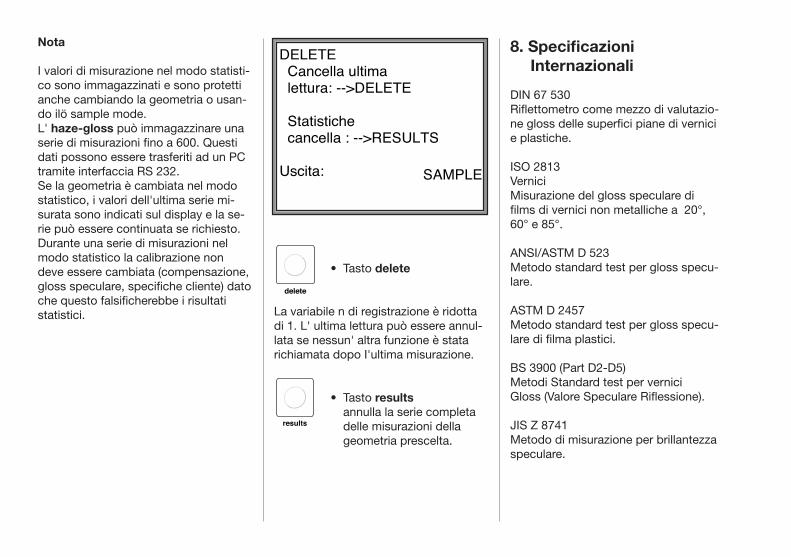
delete
results
8. Specificazioni Internazionali
Nota
I valori di misurazione nel modo statisti-co sono immagazzinati e sono protetti anche cambiando la geometria o usan-do ilö sample mode. L' haze-gloss può immagazzinare una serie di misurazioni fino a 600. Questi dati possono essere trasferiti ad un PC tramite interfaccia RS 232.Se la geometria è cambiata nel modo statistico, i valori dell'ultima serie mi-surata sono indicati sul display e la se-rie può essere continuata se richiesto.Durante una serie di misurazioni nel modo statistico la calibrazione non deve essere cambiata (compensazione, gloss speculare, specifiche cliente) dato che questo falsificherebbe i risultati statistici.
DIN 67 530 Riflettometro come mezzo di valutazio-ne gloss delle superfici piane di vernici e plastiche.
ISO 2813 Vernici Misurazione del gloss speculare di films di vernici non metalliche a 20°, 60° e 85°.
ANSI/ASTM D 523 Metodo standard test per gloss specu-lare.
ASTM D 2457 Metodo standard test per gloss specu-lare di filma plastici.
BS 3900 (Part D2-D5) Metodi Standard test per vernici Gloss (Valore Speculare Riflessione).
JIS Z 8741Metodo di misurazione per brillantezza speculare.
• Tasto delete La variabile n di registrazione è ridotta di 1. L' ultima lettura può essere annul-lata se nessun' altra funzione è stata richiamata dopo I'ultima misurazione.
• Tasto results annulla la serie completa delle misurazioni della geometria prescelta.
DELETE Cancella ultima lettura: -->DELETE
Statistiche cancella : -->RESULTS
Uscita:
SAMPLE
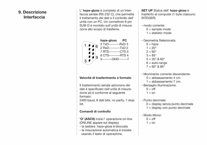
1 6
59
9. Descrizione Interfaccia
L' haze-gloss è completo di un'inter-faccia seriale (RS 232 C), che permette il trattamento dei dati e il controllo dell' unità con un PC. Un connettore 9-pin SUB-D è montato sull'unità di misura-zione allo scopo di trasferire.
haze-gloss PC3 TxD---------RxD 32 RxD---------TxD 27 RTS---------CTS 58 CTS---------RTS 45--------GND-------7
Velocità di trasferimento e formato
Il trasferimento seriale asincrono dei dati è specificato nell'unità di misura-zione ed è conforme al seguente formato:2400 baud, 8 dati bits, no parity, 1 stop bit.
Comandi di controllo
‘O’ (ASCII) inizia I' operazione on-line (ONLINE appare sul display)- la tastiera haze-gloss è bloccata- la misurazione automatica è iniziata usando il tasto di operazione.
SET UP Status dell' haze-gloss è trasferito al computer (1 byte ciascuno INTEGER)
- modo corrente: 0 = sample mode 1 = statistic mode
- Geometria Selezionata: 0 = haze 1 = 20° 2 = 60° 3 = 85° 5 = 20° & 60° 6 = auto-range 7 = 60° & 85°
- Movimento corrente discendente: 0 = abbassamento 4 cm 1 = abbassamento 7 cm.- Bersaglio illuminazione: 0 = off 1 = on
- Punto decimale: 0 = display senza punto decimale 1 = display con punto decimale
- Modo Mirror: 0 = off 1 = on
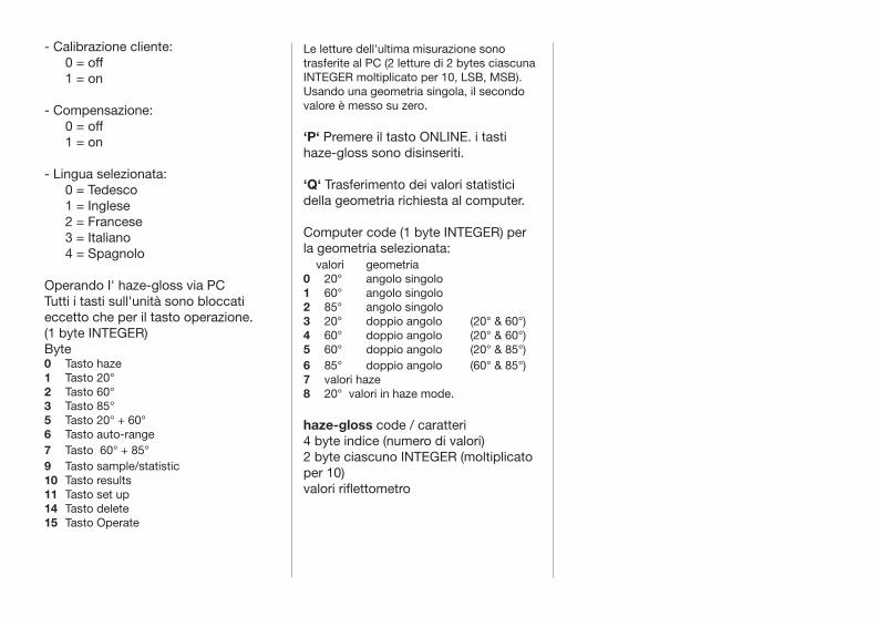
- Calibrazione cliente: 0 = off 1 = on
- Compensazione: 0 = off 1 = on
- Lingua selezionata: 0 = Tedesco 1 = Inglese 2 = Francese 3 = Italiano 4 = Spagnolo
Operando I' haze-gloss via PCTutti i tasti sull'unità sono bloccati eccetto che per il tasto operazione. (1 byte INTEGER)Byte0 Tasto haze1 Tasto 20°2 Tasto 60°3 Tasto 85°5 Tasto 20° + 60°6 Tasto auto-range7 Tasto 60° + 85°9 Tasto sample/statistic10 Tasto results11 Tasto set up14 Tasto delete15 Tasto Operate
Le letture dell'ultima misurazione sono trasferite al PC (2 letture di 2 bytes ciascuna INTEGER moltiplicato per 10, LSB, MSB). Usando una geometria singola, il secondo valore è messo su zero.
‘P‘ Premere il tasto ONLINE. i tasti haze-gloss sono disinseriti.
‘Q‘ Trasferimento dei valori statistici della geometria richiesta al computer.
Computer code (1 byte INTEGER) per la geometria selezionata: valori geometria0 20° angolo singolo1 60° angolo singolo2 85° angolo singolo3 20° doppio angolo (20° & 60°)4 60° doppio angolo (20° & 60°)5 60° doppio angolo (20° & 85°)6 85° doppio angolo (60° & 85°)7 valori haze8 20° valori in haze mode.
haze-gloss code / caratteri4 byte indice (numero di valori)2 byte ciascuno INTEGER (moltiplicato per 10) valori riflettometro

10. Dati tecnici Geometrie di misurazione: 20° & haze, 60° 85°Area illuminata (mm/in.):20° & haze 60° 85° ø 15 15 x 27 8x 60 ø 0.6 0.6 x 1.0 0.3 x 2.4
Scala misurazione:Gloss 0 - 2000 unitá glossHaze 0 - 2500 unitá glossPassaggio a modo di misura mirror:automatica o preselezionabile
Risoluzione display: 0.1 unità (scala : 0-100 unità)) 1 unità (scala : > 100 unità)
Accuratezza**:GlossRipetibilità ± 0.05 unità*Riproducibilità ± 0.3 unità*Affidabilità assoluta ± 1 unità Stabilità a lungotermine ±0.2 unità* (> 10000 misur.) Variazione temp. 0,02 unità /°C*
HazeRipetibilità ± 0.3 unità*Riproducibilità ± 2 unità*
Stabilità a lungo termine ± 0,3 unità* (> 10000 misur.)
Variazione temp. ± 0.2 unità/°C*Tempo di misu- 1,5 - 4 sec.razione: (modo dipendente)
Sorgente di luce: Lampada tungsteno (5 V/190 mA)
Detector: fotocellula silicone V (Lambda) filtrata
Display: LCD retroilluminato
Memoria 9 x 600 misurazioni statistiche: protezione dati per 10 anni da batteria
Interfaccia: RS 232 C per controllo valutazione dati via PC
Connessioni: RS 232 C: 9-pin Sub-D connettori: 15-pin Sub-D
Alimentazione 115 / 230 Velettrica: 50 / 60 Hz
Richiesta di energia: 50 VA

Fusibili: 1 AT (230 V), 1.6 AT (115 V)Scala di temp. Operazione + 10 a + 40 0C Immagazzinamento 0- a 50 0C
Dimensioni (cm):Larghezza 33 cm. / 13.0 in.profondità 40 cm. / 15.7 in.altezza 52 cm. / 10.5 in.
peso: 14,3 kg
Test marks : DIN, GS-TUV
Particolarità: Display in Inglese, Tedesco, Francese, Spagnolo, e Italiano
* Deviazione Standard** Relativo a uno standard ad alto gloss valori haze sono relativi a valori > 10 unità haze dovuti alla scala logaritmica.
Dati tecnici sono soggetti a variazione senza preavviso.
Allineamento, sostituzione di parti, manutenzione e riparazione Aprendo il coperchio o rimuovendo le parti, se non fatto manualmente, le parti attive possono essere danneggiate. E' anche possibile che i punti di connes-sione siano attivi.Prima che sia effettuato un allineamen-to, manutenzione, riparazione o ricam-bio delle parti e che lo strumento sia aperto, I'unità deve essere disconnessa da tutte le prese di corrente. Se dopo è inevitabile il caso che un allineamento, manutenzione, riparazione o ricambio sia effettuato con uno strumento acceso, I'assistenza tecnica deve essere effettuata da personale prepara-to contro eventuali pericoli. I condensatori all'interno dello strumen-to possono essere carichi anche se I'unità è stata disconnessa da tutte le prese. Assicurarsi che siano usati solo i fusibili di ricambio del tipo indicato e con la corrente nominale indicata. Usare i fusibili riparati o in corto circuito.
Istruzioni di sicurezza
Norme di sicurezza VDE
Questo strumento è conforme alle norme di sicurezza DIN 57411 Parte 1/VDE 0411 Parte 1 ed è approvato secondo DIN e VDE. Lo strumento lascia la ns. fabbrica in condizioni perfette. Al fine di mantenere questa condizione e di assicurare un'operazio-ne sicura, I'utilizzatore deve prestare particolare attenzione alle istruzioni d'uso.
Prima di usare lo strumento assicurarsi che il voltaggio usato del Vs. strumento sia identico alla tensione di rete locale. E' importante che la presa principale sia solo inserita nella presa di corrente di sicurezza. Mai annullare I'effetto protettivo usando una prolunga senza la messa a terra.
Avvertimento! Qualsiasi interruzione del conduttore a terra, dentro o fuori lo strumento può essere pericoloso.Interruzioni volontarie sono inaccettabili.
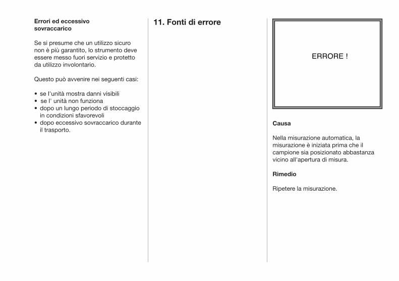
Causa
Nella misurazione automatica, la misurazione è iniziata prima che il campione sia posizionato abbastanza vicino all'apertura di misura.
Rimedio
Ripetere la misurazione.
Errori ed eccessivo sovraccarico Se si presume che un utilizzo sicuro non è più garantito, lo strumento deve essere messo fuori servizio e protetto da utilizzo involontario.
Questo può avvenire nei seguenti casi: • se I'unità mostra danni visibili • se I' unità non funziona• dopo un lungo periodo di stoccaggio in condizioni sfavorevoli • dopo eccessivo sovraccarico durante il trasporto.
11. Fonti di errore
ERRORE !
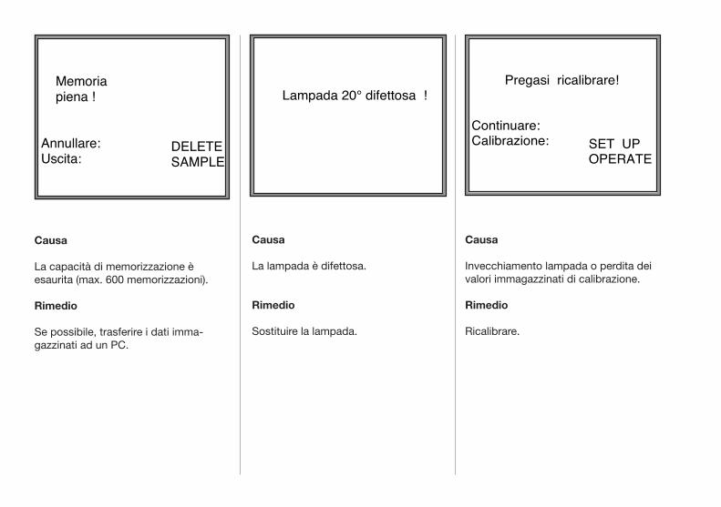
Causa
Invecchiamento lampada o perdita dei valori immagazzinati di calibrazione.
Rimedio
Ricalibrare.
Causa
La lampada è difettosa.
Rimedio
Sostituire la lampada.
Causa
La capacità di memorizzazione è esaurita (max. 600 memorizzazioni).
Rimedio
Se possibile, trasferire i dati imma-gazzinati ad un PC.
Memoria piena !
Annullare:Uscita:
DELETESAMPLE
Lampada 20° difettosa !
Pregasi ricalibrare!
Continuare:Calibrazione:
SET UPOPERATE
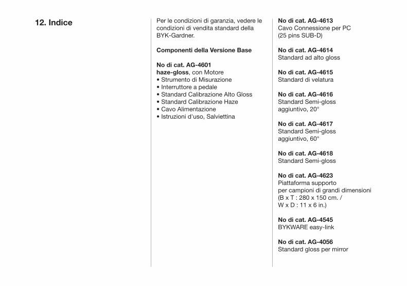
12. Indice Per le condizioni di garanzia, vedere le condizioni di vendita standard dellaBYK-Gardner.
Componenti della Versione Base
No di cat. AG-4601haze-gloss, con Motore• Strumento di Misurazione• Interruttore a pedale• Standard Calibrazione Alto Gloss• Standard Calibrazione Haze• Cavo Alimentazione• Istruzioni d'uso, Salviettina
No di cat. AG-4613Cavo Connessione per PC (25 pins SUB-D)
No di cat. AG-4614Standard ad alto gloss
No di cat. AG-4615Standard di velatura
No di cat. AG-4616Standard Semi-gloss aggiuntivo, 20°
No di cat. AG-4617Standard Semi-gloss aggiuntivo, 60°
No di cat. AG-4618Standard Semi-gloss
No di cat. AG-4623Piattaforma supporto per campioni di grandi dimensioni(B x T : 280 x 150 cm. / W x D : 11 x 6 in.)
No di cat. AG-4545BYKWARE easy-link
No di cat. AG-4056Standard gloss per mirror

EG - KonformitätserklärungEC - Declaration of Conformity
Wir / We, BYK-Gardner GmbH, Lausitzer Straße 8, D - 82538 Geretsriederklären im Sinne der EG-Richtlinie(n): / declare in accordance with the EC Directive(s):
• Elektromagnetische Verträglichkeit 89/336/EWG / Electromagnetic Compatibility 89/336/EEC• Niederspannung 73/23/EWG / Low Voltage 73/23/EEC• Maschinen 89/392/EWG / Maschines 89/392/EEC
Die Bauart des Produktes: / The construction of the product:
haze-gloss
ist entwickelt, konstruiert und gefertigt in Übereinstimmung mit vorgenannter(n) EG-Richtlinie(n). / was developed, constructed and produced in accordance with a.m. EC Directive(s).
Weitere entsprechende sicherheitsrelevante Normen wurden berücksichtigt. / Further safety relevant standards were observed.
Eine Technische Dokumentation ist vorhanden. / A Technical Documentation is available.
BYK-Gardner GmbH
Dr. Georg SchroederGeschäftsführer / Managing Director

F Déclaration de conformité - Nous, BYK-Gardner GmbH, déclarons que les produits / instruments ci-des-sus mentionnés ont été développés, produits et construits en conformité avec les directives CEE établies.
Konformitetserklæring - Vi, BYK-Gardner GmbH, erklærer herved, at ovennævnte produkter / instrumenter er udviklet, konstrueret og produceret i overensstemmelse med de angivne EU Direktiver.
Declaración de Conformidad - Nosotros, BYK-Gardner GmbH, declaramos que los productos / aparatos arriba mencionados, han sido desarrollados, construídos y fabricados en consonancia con las directrices de la CEE indicadas.
EU-yhteensopivuusvakuutus - Me, BYK-Gardner GmbH, vakuuttaa, että yllämainitut tuotteet / laitteet on kehitetty, rakennettu ja valmistettu asetettujen EU-direktiivien mukaisesti.
Dichiarazione di conformità - Noi, BYK-Gardner GmbH, dichiariamo che i suddetti prodotti / strumenti sono stati sviluppati, construiti et prodotti in conformità con le Direttive EC stabilite.
Overeenkomstigheidsverklaring - Wij, BYK-Gardner GmbH, verklaren hierbij dat bovengenoemd produkten / apparaten zijn ontworpen, gekonstrueerd en vervaardigd overeenkomstig de genoemde EG-richtlijnen.
Declaração de Conformidade - Nós, BYK-Gardner GmbH, declaramos pela presente, que os produtos / aparelhos acima indicados são desenvolvidos, construídos e produzidos de acordo com as Directivas CE mencionadas.
∆η´λωση ΕΚ−συµµο´ρφωσηs − Εµει´s, η BYK-Gardner GmbH, δηλω´νουµε µε το παρο´ν ο´τι τα ωs α´νω αναφερο´µενα προι´ο´ντα / συσκευε´s αναπτυ´χθηκαν σχεδια´στηκαν και κατασκευα´στηκαν σε συµφωνι´α µε τιs προαναφερο´´µενεs οδηγι´εs ΕΚ.
Deklaration av överenstämmelse - Vi, BYK-Gardner GmbH, deklarerar härmed att ovanstående produkter / instrument har blivit utvecklade och tillverkade i enlighet med de gällande EU direktiven.
GR
S
NL
I
SF
DK
E
P
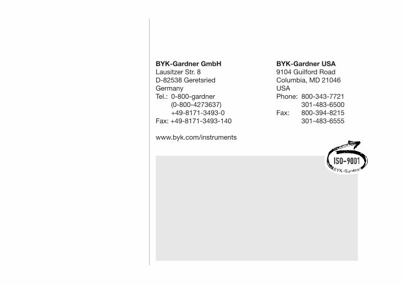
BYK-Gardner USA 9104 Guilford RoadColumbia, MD 21046USAPhone: 800-343-7721 301-483-6500Fax: 800-394-8215 301-483-6555
BYK-Gardner GmbHLausitzer Str. 8D-82538 GeretsriedGermanyTel.: 0-800-gardner (0-800-4273637) +49-8171-3493-0Fax: +49-8171-3493-140
www.byk.com/instruments
BYK-Gardner USA 9104 Guilford RoadColumbia, MD 21046USAPhone: 800-343-7721 301-483-6500Fax: 800-394-8215 301-483-6555
BYK-Gardner GmbHLausitzer Str. 8D-82538 GeretsriedGermanyTel.: 0-800-gardner (0-800-4273637) +49-8171-3493-0Fax: +49-8171-3493-140
www.bykgardner.com

228 012 718 EDFI 0811