hb00e opl sp7 | rev. 11/20 may 2011 - int technics · hb00e_opl_sp7 | rev. 11/20 may 2011 . ......
TRANSCRIPT

VIPA
SPEED7 | Operation List | Manual HB00E_OPL_SP7 | Rev. 11/20
May 2011

Copyright © VIPA GmbH. All Rights Reserved.
This document contains proprietary information of VIPA and is not to be disclosed or used except in accordance with applicable agreements.
This material is protected by the copyright laws. It may not be reproduced, distributed, or altered in any fashion by any entity (either internal or external to VIPA), except in accordance with applicable agreements, contracts or licensing, without the express written consent of VIPA and the business management owner of the material.
For permission to reproduce or distribute, please contact: VIPA, Gesellschaft für Visualisierung und Prozessautomatisierung mbH Ohmstraße 4, D-91074 Herzogenaurach, Germany Tel.: +49 (91 32) 744 -0 Fax.: +49 9132 744 1864 EMail: [email protected] http://www.vipa.de Note
Every effort has been made to ensure that the information contained in this document was complete and accurate at the time of publishing. Nevertheless, the authors retain the right to modify the information. This customer document describes all the hardware units and functions known at the present time. Descriptions may be included for units which are not present at the customer site. The exact scope of delivery is described in the respective purchase contract.
CE Conformity
Hereby, VIPA GmbH declares that the products and systems are in compliance with the essential requirements and other relevant provisions of the following directives:
• 2004/108/EC Electromagnetic Compatibility Directive • 2006/95/EC Low Voltage Directive
Conformity is indicated by the CE marking affixed to the product.
Conformity Information
For more information regarding CE marking and Declaration of Conformity (DoC), please contact your local VIPA customer service organization.
Trademarks
VIPA, SLIO, System 100V, System 200V, System 300V, System 300S, System 400V, System 500S and Commander Compact are registered trademarks of VIPA Gesellschaft für Visualisierung und Prozessautomatisierung mbH.
SPEED7 is a registered trademark of profichip GmbH.
SIMATIC, STEP, SINEC, S7-300 and S7-400 are registered trademarks of Siemens AG.
Microsoft und Windows are registered trademarks of Microsoft Inc., USA.
Portable Document Format (PDF) and Postscript are registered trademarks of Adobe Systems, Inc.
All other trademarks, logos and service or product marks specified herein are owned by their respective companies.
Information product support
Contact your local VIPA Customer Service Organization representative if you wish to report errors or questions regarding the contents of this document. If you are unable to locate a customer service center, contact VIPA as follows:
VIPA GmbH, Ohmstraße 4, 91074 Herzogenaurach, Germany
Telefax:+49 9132 744 1204 EMail: [email protected]
Technical support
Contact your local VIPA Customer Service Organization representative if you encounter problems with the product or have questions regarding the product. If you are unable to locate a customer service center, contact VIPA as follows:
VIPA GmbH, Ohmstraße 4, 91074 Herzogenaurach, Germany
Telephone: +49 9132 744 1150/1180 (Hotline) EMail: [email protected]

Manual VIPA Operation List SPEED7 Contents
HB00E - OPL_SP7 - Rev. 11/20 i
Contents
About this manual .................................................................................... 1 Chapter 1 Instruction List ................................................................ 1-1
Alphabetical instruction list ................................................................... 1-2 Abbreviations ....................................................................................... 1-4 Differences between SPEED7 and 300V programming........................ 1-6 Registers.............................................................................................. 1-8 Addressing examples ........................................................................... 1-9 Math instructions ................................................................................ 1-11 Block instructions ............................................................................... 1-13 Program display and null instruction instructions................................ 1-14 Edge-triggered instructions ................................................................ 1-14 Load instructions ................................................................................ 1-15 Shift instructions................................................................................. 1-18 Setting/resetting bit addresses ........................................................... 1-19 Jump instructions ............................................................................... 1-21 Transfer instructions........................................................................... 1-22 Data type conversion instructions....................................................... 1-25 Comparison instructions..................................................................... 1-26 Combination instructions (Bit)............................................................. 1-27 Combination instructions (Word) ........................................................ 1-33 Timer instructions............................................................................... 1-33 Counter instructions ........................................................................... 1-34
Chapter 2 Organization Blocks ....................................................... 2-1 Overview .............................................................................................. 2-2 OB 1 - Main program............................................................................ 2-3 OB 10, OB 11 - Time-of-day Interrupt .................................................. 2-5 OB 20, OB 21 - Time-delay Interrupt.................................................... 2-7 OB 28, 29, 32, 33, 34, 35 - Watchdog Interrupt.................................... 2-8 OB 40, OB 41 - Hardware Interrupt .................................................... 2-10 OB 57 - Manufacturer Specific Interrupt OB....................................... 2-12 OB 80 - Time Error............................................................................. 2-13 OB 81 - Power supply Error................................................................ 2-16 OB 82 - Diagnostic Interrupt............................................................... 2-17 OB 85 - Program execution Error ....................................................... 2-19 OB 86 - Slave Failure / Restart........................................................... 2-23 OB 100 - Reboot ................................................................................ 2-25 OB 121 - Programming Error (Synchronous error) ............................. 2-27 OB 122 - Periphery access Error........................................................ 2-30
Chapter 3 Integrated SFBs .............................................................. 3-1 Overview .............................................................................................. 3-2 SFB 0 - CTU - Up-counter.................................................................... 3-3 SFB 1 - CTD - Down-counter ............................................................... 3-4 SFB 2 - CTUD - Up-Down counter ....................................................... 3-5 SFB 3 - TP - Create pulse .................................................................... 3-7 SFB 4 - TON - Create turn-on delay..................................................... 3-9

Contents Manual VIPA Operation List SPEED7
ii HB00E - OPL_SP7 - Rev. 11/20
SFB 5 - TOF - Create turn-off delay ................................................... 3-11 SFB 32 - DRUM - Realize a step-by-step switch ................................ 3-13 SFB 31 - NOTIFY_8P - Messages without Acknowl. Display (8x) ....... 3-18 SFB 33 - ALARM - Messages with Acknowledgment Display............. 3-21 SFB 34 - ALARM_8 - Messages without Associated Values (8x) ....... 3-24 SFB 35 - ALARM_8P - Messages with Associated Values (8x).......... 3-26 SFB 36 - NOTIFY - Messages without Acknowledgment Display ....... 3-29 SFB 47 - COUNT - Counter controlling .............................................. 3-31 SFB 52 - RDREC - Reading a Data Record from a DP-V1 slave ....... 3-35 SFB 53 - WRREC - Writing a Data Record in a DP-V1 slave............. 3-37 SFB 54 - RALRM - Receiving an interrupt from a DP-V1 slave .......... 3-39
Chapter 4 Integrated Standard FBs ................................................ 4-1 Overview Integrated Standard-FBs ...................................................... 4-2 Open Communication - FB 63 ... FB 68................................................ 4-3 UDT 65 - TCON_PAR .......................................................................... 4-5 UDT 66 - TCON_ADR.......................................................................... 4-9 Parameterization - Example ............................................................... 4-10 FB 63 - TSEND - Sending data - TCP native and ISO on TCP........... 4-12 FB 64 - TRCV - Receiving Data - TCP native and ISO on TCP.......... 4-15 FB 65 - TCON - Establishing a connection......................................... 4-19 FB 66 - TDISCON - Terminating a connection ................................... 4-22 FB 67 - TUSEND - Sending data - UDP............................................. 4-24 FB 68 - TURCV - Receiving data - UDP............................................ 4-27
Chapter 5 Integrated Standard SFCs .............................................. 5-1 Overview Integrated standard SFCs..................................................... 5-3 General and Specific Error Information RET_VAL................................ 5-5 SFC 0 - SET_CLK - Set system clock .................................................. 5-8 SFC 1 - READ_CLK - Read system clock ............................................ 5-9 SFC 2 ... 4 - Run-time meter .............................................................. 5-10 SFC 2 - SET_RTM - Set run-time meter............................................. 5-11 SFC 3 - CTRL_RTM - Control run-time meter .................................... 5-12 SFC 4 - READ_RTM - Read run-time meter....................................... 5-13 SFC 5 - GADR_LGC - Logical address of a channel .......................... 5-14 SFC 6 - RD_SINFO - Read start information...................................... 5-16 SFC 12 - D_ACT_DP - Activating and Deactivating of DP-Slaves...... 5-18 SFC 13 - DPNRM_DG - Read diagnostic data of a DP-slave............. 5-23 SFC 14 - DPRD_DAT - Read consistent data .................................... 5-26 SFC 15 - DPWR_DAT - Write consistent data ................................... 5-28 SFC 17 - ALARM_SQ and SFC 18 - ALARM_S ................................. 5-30 SFC 19 - ALARM_SC - Acknowledgement state last Alarm ............... 5-33 SFC 20 - BLKMOV - Block move........................................................ 5-34 SFC 21 - FILL - Fill a field .................................................................. 5-36 SFC 22 - CREAT_DB - Create a data block ....................................... 5-38 SFC 23 - DEL_DB - Deleting a data block.......................................... 5-40 SFC 24 - TEST_DB - Test data block ................................................ 5-41 SFC 25 - COMPRESS - Compressing the User Memory.................... 5-42 SFC 28 ... 31 - Time-of-day interrupt.................................................. 5-43 SFC 32 - SRT_DINT - Start time-delay interrupt ................................ 5-47
Manual VIPA Operation List SPEED7 Contents
HB00E - OPL_SP7 - Rev. 11/20 iii
SFC 33 - CAN_DINT - Cancel time-delay interrupt............................. 5-48 SFC 34 - QRY_DINT - Query time-delay interrupt.............................. 5-49 SFC 36 - MSK_FLT - Mask synchronous errors................................. 5-50 SFC 37 - DMSK_FLT - Unmask synchronous errors.......................... 5-51 SFC 38 - READ_ERR - Read error register........................................ 5-52 SFC 39 - DIS_IRT - Disabling interrupts............................................. 5-53 SFC 40 - EN_IRT - Enabling interrupts .............................................. 5-55 SFC 41 - DIS_AIRT - Delaying interrupts ........................................... 5-56 SFC 42 - EN_AIRT - Enabling delayed interrupts............................... 5-57 SFC 43 - RE_TRIGR - Retrigger the watchdog.................................. 5-57 SFC 44 - REPL_VAL - Replace value to AKKU1................................ 5-58 SFC 46 - STP - STOP the CPU.......................................................... 5-58 SFC 47 - WAIT - Delay the application program ................................ 5-59 SFC 49 - LGC_GADR - Read the slot address................................... 5-60 SFC 50 - RD_LGADR - Read all logical addresses of a module ........ 5-61 SFC 50 - RD_LGADR - Read all logical addresses of a module ........ 5-61 SFC 51 - RDSYSST - Read system status list SSL............................ 5-62 SFC 52 - WR_USMSG - Write user entry into diagnostic buffer......... 5-64 SFC 54 - RD_DPARM - Read predefined parameter ......................... 5-68 SFC 55 - WR_PARM - Write dynamic parameter............................... 5-70 SFC 56 - WR_DPARM - Write default parameter............................... 5-73 SFC 57 - PARM_MOD - Parameterize module................................... 5-75 SFC 58 - WR_REC - Write record...................................................... 5-77 SFC 59 - RD_REC - Read record....................................................... 5-80 SFC 64 - TIME_TCK - Read system time tick .................................... 5-83 SFC 65 - X_SEND - Send data .......................................................... 5-84 SFC 66 - X_RCV - Receive data ........................................................ 5-87 SFC 67 - X_GET - Read data ............................................................ 5-92 SFC 68 - X_PUT - Write data............................................................. 5-96 SFC 69 - X_ABORT - Disconnect ...................................................... 5-99 SFC 69 - X_ABORT - Disconnect ...................................................... 5-99 SFC 81 - UBLKMOV - Copy data area without gaps ........................ 5-102 SFC 102 - RD_DPARA - Reading Predefined Parameters............... 5-104 SFC 105 - READ_SI - Reading Dynamic System Resources........... 5-105 SFC 106 - DEL_SI - Reading Dynamic System Resources.............. 5-108 SFC 107 - ALARM_DQ and SFC 108 - ALARM_D........................... 5-110
Chapter 6 VIPA specific blocks ....................................................... 6-1 Overview .............................................................................................. 6-2 Include VIPA library.............................................................................. 6-4 Siemens S7 Communication - FB/SFB 8 ... FB 55 ............................... 6-5 FB/SFB 8 - USEND - Uncoordinated data transmission ....................... 6-6 FB/SFB 9 - URCV - Uncoordinated data reception............................... 6-8 FB/SFB 12 - BSEND - Sending data in blocks ................................... 6-10 FB/SFB 13 - BRCV - Receiving data in blocks ................................... 6-13 FB/SFB 14 - GET - Remote CPU read............................................... 6-16 FB/SFB 15 - PUT - Remote CPU write............................................... 6-18 FB 55 - IP_CONFIG - Progr. Communication Connections ................ 6-20 FB 60 - SEND - Send to System SLIO CP 040 .................................. 6-34
Contents Manual VIPA Operation List SPEED7
iv HB00E - OPL_SP7 - Rev. 11/20
FB 61 - RECEIVE - Receive from System SLIO CP 040 .................... 6-36 FC 5 - AG_SEND / FC 6 - AG_RECV - CP 343 communication......... 6-38 FC 10 - AG_CNTRL - CP 343 communication ................................... 6-43 FC 200 - IBS_INIT.............................................................................. 6-50 FC 202 - IBS_SERVICE..................................................................... 6-52 FC 204 - IBS_LOOP, FC 205 - IBS_CYCLE ...................................... 6-54 FC 206 - IBS_IRQ .............................................................................. 6-56 FC 207 - IBS_PCP ............................................................................. 6-57 FC 208 - IBS_DIAG............................................................................ 6-59 SFB 7 - uS_TIME and SFC 53 - uS_TICK - Time measurement ........ 6-60 SFB 239 - FUNC ................................................................................ 6-61 SFC 193 - AI_OSZI - Oscilloscope-/FIFO function ............................. 6-62 SFC 194 - DP_EXCH......................................................................... 6-65 MMC access - SFC 208...215 and SFC 195....................................... 6-67 SFC 208 - FILE_OPN......................................................................... 6-68 SFC 209 - FILE_CRE......................................................................... 6-69 SFC 210 - FILE_CLO......................................................................... 6-70 SFC 211 - FILE_RD ........................................................................... 6-71 SFC 212 - FILE_WR .......................................................................... 6-72 SFC 213 - FILE_SEK ......................................................................... 6-74 SFC 214 - FILE_REN......................................................................... 6-75 SFC 215 - FILE_DEL ......................................................................... 6-76 SFC 195 - FILE_ATT.......................................................................... 6-77 PtP communication - SFC 216...218 .................................................. 6-78 SFC 216 - SER_CFG ......................................................................... 6-79 SFC 217 - SER_SND ......................................................................... 6-82 SFC 218 - SER_RCV ......................................................................... 6-86 SFC 219 - CAN_TLGR - CANopen communication........................... 6-88 SFC 254 - RW_SBUS - IBS communication ...................................... 6-91
Chapter 7 System Status List SSL .................................................. 7-1 Overview SSL....................................................................................... 7-2 Overview - SSL partial lists................................................................... 7-3 Module Identification - SSL-ID: xy11h .................................................. 7-4 CPU Characteristics - SSL-ID: xy12h ................................................... 7-5 Memory Areas - SSL-ID: xy13h............................................................ 7-7 System areas - SSL-ID: xy14h ............................................................. 7-8 Component Identification - SSL-ID: xy1Ch ........................................... 7-9 Interrupt Status - SSL-ID: xy22h......................................................... 7-10 Communication Status Data - SSL-ID: xy32h..................................... 7-12 Status of the Module LEDs - SSL-ID: xy74h....................................... 7-14 Status Information CPU - SSL-ID: xy91h............................................ 7-15 Station Status Information - SSL-ID: xy92h ........................................ 7-18 Diagnostic Buffer - SSL-ID: xyA0h ..................................................... 7-20 Diagnostic Information - SSL-ID: 00B1h............................................. 7-21 Diagnostic Record set 1 - SSL-ID: 00B2h .......................................... 7-22 Diagnostic Data - SSL-ID: 00B3h ....................................................... 7-23 Diagnostic Data of a DP slave - SSL-ID: 00B4h ................................. 7-24

Manual VIPA Operation List SPEED7 About this manual
HB00E - OPL_SP7 - Rev. 11/20 1
About this manual
This manual provides you with a comprehensive overview of the blocks integrated to the VIPA SPEED7 CPUs. Described are command list, integrated OBs, SFBs, SFCs and the VIPA specific blocks.
Chapter 1: Instruction list This chapter lists the available commands of the SPEED7 CPUs from VIPA. The instruction list intends to give you an overview over the commands and their syntax. The commands are sorted by topics in alphabetical order. Chapter 2: Organization Blocks Here the description of the integrated organization blocks of the VIPA SPEED7 CPUs may be found. Chapter 3: Integrated SFBs The description of the integrated function blocks of the VIPA SPEED7 CPUs may be found here. Chapter 4: Integrated Standard FBs Here the description of the integrated standard FBs of the SPEED7 CPUs from VIPA may be found. The description of the FBs of the VIPA library may be found at the chapter "VIPA specific blocks". Chapter 5: Integrated Standard SFCs Here the description of the integrated standard SFCs of the SPEED7 CPUs from VIPA may be found. The description of the SFCs of the VIPA library may be found at the chapter "VIPA specific blocks". Chapter 6: VIPA specific blocks In this chapter you find the description of the VIPA specific blocks that are exclusively used with CPUs from VIPA Chapter 7: System Status Lists SSL This chapter describes all the partial lists of the system status list, readable via SFC 51 RDSYSST or via Hardware configurator.
Overview

About this manual Manual VIPA Operation List SPEED7
2 HB00E - OPL_SP7 - Rev. 11/20
This manual provides you with the instruction list and the description of the integrated blocks that are exclusively may be used with the SPEED7 CPUs from VIPA.
The manual is targeted at users who have a background in automation technology.
The manual consists of chapters. Every chapter provides a self-contained description of a specific topic.
The following guides are available in the manual: • an overall table of contents at the beginning of the manual • an overview of the topics for every chapter
The manual is available in: • printed form, on paper • in electronic form as PDF-file (Adobe Acrobat Reader)
Important passages in the text are highlighted by following icons and headings:
Danger! Immediate or likely danger. Personal injury is possible.
Attention! Damages to property is likely if these warnings are not heeded.
Note! Supplementary information and useful tips.
Objective and contents
Target audience
Structure of the manual
Guide to the document
Availability
Icons Headings
Manual VIPA Operation List SPEED7 Chapter 1 Instruction List
HB00E - OPL_SP7 - Rev. 11/20 1-1
Chapter 1 Instruction List
The following chapter lists the available commands of the SPEED7 CPUs from VIPA. The instruction list intends to give you an overview over the commands and their syntax. The commands are sorted by topics in alphabetical order. Via the content the different topics are available. The alphabetical instruction list gives you direct access to the instructions. For the parameters are integrated in the instruction list, there is no extra parameter list.
Topic Page Chapter 1 Instruction List ................................................................ 1-1
Alphabetical instruction list ................................................................... 1-2 Abbreviations ....................................................................................... 1-4 Differences between SPEED7 and 300V programming ........................ 1-6 Registers.............................................................................................. 1-8 Addressing examples ........................................................................... 1-9 Math instructions ................................................................................ 1-11 Block instructions ............................................................................... 1-13 Program display and null instruction instructions ................................ 1-14 Edge-triggered instructions................................................................. 1-14 Load instructions ................................................................................ 1-15 Shift instructions ................................................................................. 1-18 Setting/resetting bit addresses ........................................................... 1-19 Jump instructions ............................................................................... 1-21 Transfer instructions........................................................................... 1-22 Data type conversion instructions....................................................... 1-25 Comparison instructions ..................................................................... 1-26 Combination instructions (Bit)............................................................. 1-27 Combination instructions (Word) ........................................................ 1-33 Timer instructions ............................................................................... 1-33 Counter instructions ........................................................................... 1-34
Overview
Content

Chapter 1 Instruction List Manual VIPA Operation List SPEED7
1-2 HB00E - OPL_SP7 - Rev. 11/20
Alphabetical instruction list
Instruction Page Instruction Page ) 1-29 + 1-12 +AR1 1-12 +AR2 1-12 +I 1-11 +D 1-11 +R 1-11 -D 1-11 -I 1-11 -R 1-11 *D 1-11 *I 1-11 *R 1-11 /D 1-11 /I 1-11 /R 1-11 = 1-19 ==D 1-26 ==I 1-26 ==R 1-26 <=D 1-26 <=I 1-26 <=R 1-26 <D 1-26 <I 1-26 <R 1-26 <>D 1-26 <>I 1-26 <>R 1-26 >=D 1-26 >=I 1-26 >=R 1-26 >D 1-26 >I 1-26 >R 1-26 ABS 1-11 ACOS 1-12 ASIN 1-12 ATAN 1-12 AUF 1-13 BE 1-13 BEA 1-13
BEB 1-13 BLD 1-14 BTD 1-25 BTI 1-25 CALL 1-13 CC 1-13 CLR 1-20 COS 1-12 DEC 1-24 DTB 1-25 DTR 1-25 EXP 1-12 FN 1-14 FP 1-14 FR 1-33, 1-34 INC 1-24 INVD 1-25 INVI 1-25 ITB 1-25 ITD 1-25 L 1-15, 1-16, 1-17, 1-24 LAR1 1-23 LAR2 1-23 LC 1-17 LN 1-12 LOOP 1-21 MOD 1-11 NEGD 1-25 NEGI 1-25 NEGR 1-11 NOP 1-14 NOT 1-20 O 1-27, 1-29, 1-30,
1-31 O( 1-29 OD 1-33 ON 1-28, 1-30, 1-32 ON( 1-29 OW 1-33 POP 1-24 PUSH 1-24

Manual VIPA Operation List SPEED7 Chapter 1 Instruction List
HB00E - OPL_SP7 - Rev. 11/20 1-3
R 1-19, 1-33, 1-34 RLD 1-18 RLDA 1-18 RND 1-25 RND+ 1-25 RND- 1-25 RRD 1-18 RRDA 1-18 S 1-19, 1-34 SA 1-33 SAVE 1-20 SE 1-33 SET 1-20 SI 1-33 SIN 1-12 SLD 1-18 SLW 1-18 SPA 1-21 SPB 1-21 SPBB 1-21 SPBI 1-21 SPBIN 1-21 SPBN 1-21 SPBNB 1-21 SPL 1-21 SPM 1-21 SPMZ 1-21 SPN 1-21 SPO 1-21 SPP 1-21 SPPZ 1-21 SPS 1-21 SPU 1-21 SPZ 1-21 SQR 1-12 SQRT 1-12 SRD 1-18
SRW 1-18 SS 1-33 SSD 1-18 SSI 1-18 SV 1-33 T 1-22, 1-23, 1-24 TAD 1-24 TAK 1-24 TAN 1-12 TAR 1-24 TAR1 1-23 TAR2 1-24 TAW 1-24 TDB 1-13 TRUNC 1-25 U 1-27, 1-30, 1-31 U( 1-29 UC 1-13 UD 1-33 UN 1-27, 1-30, 1-31 UN( 1-29 UW 1-33 X 1-28, 1-30, 1-32 X( 1-29 XN 1-28, 1-30, 1-32 XN( 1-29 XOD 8-30 XOW 1-33 ZR 1-34 ZV 1-34

Chapter 1 Instruction List Manual VIPA Operation List SPEED7
1-4 HB00E - OPL_SP7 - Rev. 11/20
Abbreviations
Abbreviation Description /FC First check bit 2# Binary constant a Byte address
ACCU Register for processing bytes, words and double words AR Address registers, contain the area-internal or area-
crossing addresses for the instructions addressed register-indirect
b Bit address B area-crossing, register-indirect addressed byte
B (b1,b2) Constant, 2byte B (b1,b2,b3,b4) Constant, 4byte
B#16# Byte hexadecimal BR Binary result c Operand range C Counter C# Counter constant (BCD-coded)
CC0 Condition code CC1 Condition code
D area-crossing, register-indirect addressed double word D# IEC date constant DB Data block
DBB Data byte in the data block DBD Data double word in the data block DBW Data word in the data block DBX Data bit in the data block DI Instance data block
DIB Data byte in the instance DB DID Data double word in the instance DB DIW Data word in the instance DB DIX Data bit in the instance DB
DW#16# Double word hexadecimal f Timer/Counter No.
FB Function block FC Functions g Operand range h Operand range I Input (in the PII) i Operand range i8 Integer (8bit)
i16 Integer (16bit) i32 Integer (32bit) IB Input byte (in the PII) ID Input double word (in the PII) IW Input word (in the PII) k8 Constant (8bit) k16 Constant (16bit) k32 Constant (32bit)
continued ...

Manual VIPA Operation List SPEED7 Chapter 1 Instruction List
HB00E - OPL_SP7 - Rev. 11/20 1-5
... continue Abbreviation Description
L Local data L# Integer constant (32bit)
LABEL Symbolic jump address (max. 4 characters) LB Local data byte LD Local data double word LW Local data word m Pointer constant P#x.y (pointer) M Bit memory bit
MB Bit memory byte MD Bit memory double word MW Bit memory word
n Binary constant OB Organization block OR Or OS Stored overflow OV Overflow p Hexadecimal constant
P# Pointer constant PIQ Process image of the outputs PII Process image of the inputs PIB Periphery input byte (direct periphery access) PID Periphery input double word (direct periphery access) PIW Periphery input word (direct periphery access) PQB Periphery output byte (direct periphery access) PQD Periphery output double word (direct periphery access) PQW Periphery output word (direct periphery access)
Q Output (in the PIQ) q Real number (32bit floating-point number)
QB Output byte (in the PIQ) QD Output double word (in the PIQ) QW Output word (in the PIQ)
r Block no. RLO Result of (previous) logic instruction S5T# S5 time constant (16bit), loads the S5-Timer SFB System function block SFC System function STA Status
T Timer (times) T# Time constant (16/32bit)
TOD# IEC time constant W area-crossing, register-indirect addressed word
W#16# Word hexadecimal

Chapter 1 Instruction List Manual VIPA Operation List SPEED7
1-6 HB00E - OPL_SP7 - Rev. 11/20
Differences between SPEED7 and 300V programming
The SPEED7-CPUs lean in the command processing against the S7-400 from Siemens and differs here to the S7-300 from Siemens. These differences are listed below. In the following, the S7-318 from Siemens is counted for the S7-400 series from Siemens.
In opposite to the System 300V, the SPEED7-CPUs, Siemens S7-400 and CPU 318 use the status register bits OR, STA, /ER. If your user application is based upon the circumstance that the mentioned bits in the status register are always zero (like S7-300 from Siemens), the program is not executable at SPEED7-CPUs, Siemens S7-400 and CPU 318.
The CPUs of the System 300V contain 2 ACCUs. At an arithmetic operation the content of the 2nd ACCU is not altered. Whereas the SPEED7-CPUs provide 4 ACCUs. After an arithmetic operation (+I, -I, *I, /I, +D, -D, *D, /D, MOD, +R, -R, *R, /R) the content of ACCU 3 and ACCU 4 is loaded into ACCU 3 and 2. This may cause conflicts in applications that presume an unmodified ACCU2.
The missing of the implementation of the start command bit /ER in the System 300V may cause, under certain circumstances, deviations in the command execution of bit commands between S7-300 and S7-400 res. SPEED7, especially at a jump to a bit conjunction chain.
General
Status register
ACCU handling at arithmetic operations
RLO at jumps

Manual VIPA Operation List SPEED7 Chapter 1 Instruction List
HB00E - OPL_SP7 - Rev. 11/20 1-7
Example A: A I0.0
A M1.1
= M2.0 // RLO =1 Command end
JU =J001 // jumps
.....
A M7.6
A M3.0
A M3.1
JO01: A Q2.2 // after the jump...
// 300V further combines
// This command is used by VIPA SPEED7,
// Siemens S7-400 and CPU 318 as first request
Example B: A I0.0
A M1.1
= M2.0 // RLO =1 command end
A Q3.3 // first request
JU =J001 // jumps
.....
A M3.0
A M3.1
JO01: A M3.2 // after jump
..... // the CPUs further combine
At setting a timer or counter, a valid BCD value must be present in AKKU1. The proof of this BCD value is in the System 300V only executed when timer or counter are taken over (edge change). The SPEED7-CPUs (like the S7-400 from Siemens) always execute the verification.
Example: ......
A I5.4
L MW20
S T30 // 300V only proofs if timer is actively
// executed
// SPEED7, Siemens S7-400 and CPU 318
// always proof (also when no condition is
// present)
......
Examples RLO at jumps
BCD consistency
Chapter 1 Instruction List Manual VIPA Operation List SPEED7
1-8 HB00E - OPL_SP7 - Rev. 11/20
Registers
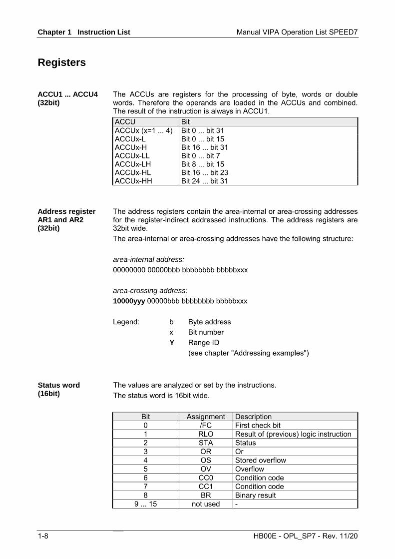
The ACCUs are registers for the processing of byte, words or double words. Therefore the operands are loaded in the ACCUs and combined. The result of the instruction is always in ACCU1. ACCU Bit ACCUx (x=1 ... 4) Bit 0 ... bit 31 ACCUx-L Bit 0 ... bit 15 ACCUx-H Bit 16 ... bit 31 ACCUx-LL Bit 0 ... bit 7 ACCUx-LH Bit 8 ... bit 15 ACCUx-HL Bit 16 ... bit 23 ACCUx-HH Bit 24 ... bit 31
The address registers contain the area-internal or area-crossing addresses for the register-indirect addressed instructions. The address registers are 32bit wide. The area-internal or area-crossing addresses have the following structure: area-internal address: 00000000 00000bbb bbbbbbbb bbbbbxxx area-crossing address: 10000yyy 00000bbb bbbbbbbb bbbbbxxx Legend: b Byte address x Bit number Y Range ID (see chapter "Addressing examples")
The values are analyzed or set by the instructions. The status word is 16bit wide.
Bit Assignment Description 0 /FC First check bit 1 RLO Result of (previous) logic instruction 2 STA Status 3 OR Or 4 OS Stored overflow 5 OV Overflow 6 CC0 Condition code 7 CC1 Condition code 8 BR Binary result
9 ... 15 not used -
ACCU1 ... ACCU4 (32bit)
Address register AR1 and AR2 (32bit)
Status word (16bit)

Manual VIPA Operation List SPEED7 Chapter 1 Instruction List
HB00E - OPL_SP7 - Rev. 11/20 1-9
Addressing examples
Addressing example Description Immediate addressing L +27 Load 16bit integer constant "27" in ACCU1 L L#-1 Load 32bit integer constant "-1" in ACCU1 L 2#1010101010101010 Load binary constant in ACCU1 L DW#16#A0F0_BCFD Load hexadecimal constant in ACCU1. L 'End' Load ASCII code in ACCU1 L T#500ms Load time value in ACCU1 L C#100 Load counter value in ACCU1 L B#(100,12) Load constant as 2byte L B#(100,12,50,8) Load constant as 4byte L P#10.0 Load area-internal pointer in ACCU1 L P#E20.6 Load area-crossing pointer in ACCU1 L -2.5 Load real number in ACCU1 L D#1995-01-20 Load date L TOD#13:20:33.125 Load time-of-day Direct addressing A I 0.0 AND operation of input bit 0.0 L IB 1 Load input byte 1 in ACCU1 L IW 0 Load input word 0 in ACCU1 L ID 0 Load input double word 0 in ACCU1 Indirect addressing timer/counter SP T [LW 8] Start timer; timer no. is in local data word 8 CU C [LW 10] Start counter; counter no. is in local data word 10 Memory-indirect, area-internal addressing A I [LD 12] e.g.: LP#22.2 T LD 12 A I [LD 12]
AND instruction; input address is in local data double word 12 as pointer
A I [DBD 1] AND instruction; input address is in data double word 1 of the DB as pointer
A Q [DID 12] AND instruction; output address is in data double word 12 of the instance DB as pointer
A Q [MD 12] AND instruction; output address is in bit memory double word 12 as pointer
Register-indirect, area-internal addressing A I [AR1,P#12.2] AND instruction; input address is calculated
"pointer value in address register 1 + pointer P#12.2"
continued ...
Chapter 1 Instruction List Manual VIPA Operation List SPEED7
1-10 HB00E - OPL_SP7 - Rev. 11/20
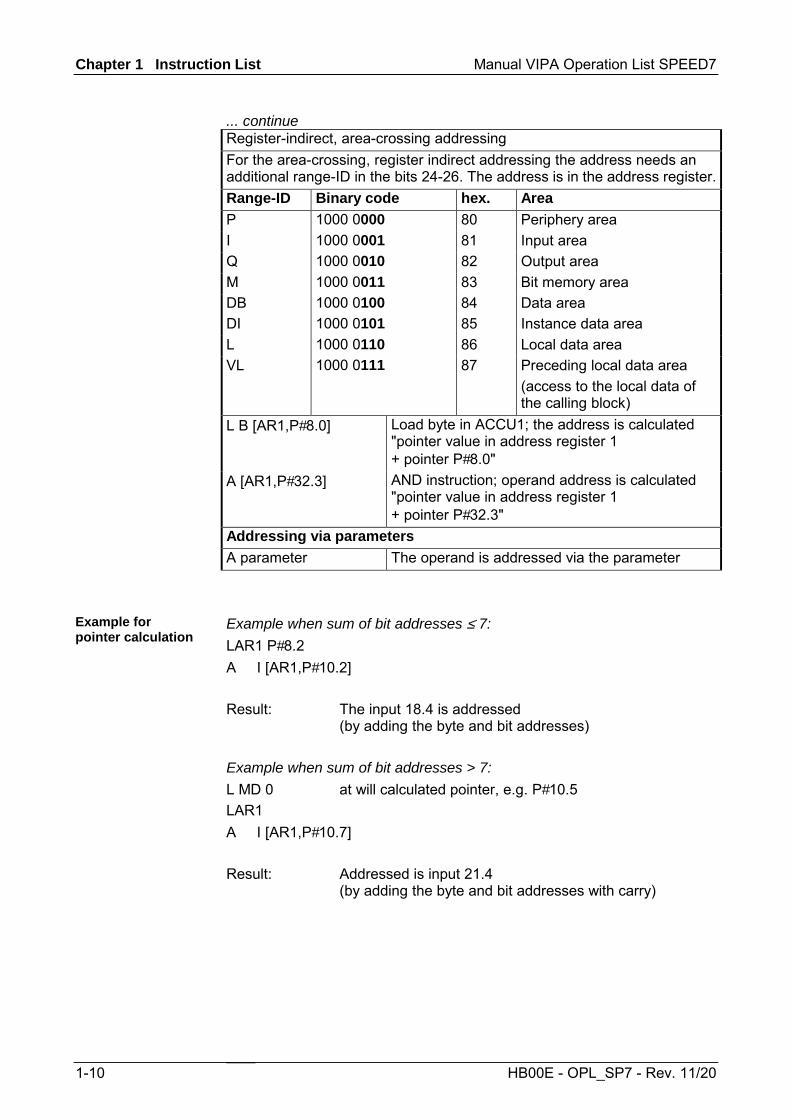
... continue Register-indirect, area-crossing addressing For the area-crossing, register indirect addressing the address needs an additional range-ID in the bits 24-26. The address is in the address register.Range-ID Binary code hex. Area P 1000 0000 80 Periphery area I 1000 0001 81 Input area Q 1000 0010 82 Output area M 1000 0011 83 Bit memory area DB 1000 0100 84 Data area DI 1000 0101 85 Instance data area L 1000 0110 86 Local data area VL 1000 0111 87 Preceding local data area
(access to the local data of the calling block)
L B [AR1,P#8.0] Load byte in ACCU1; the address is calculated "pointer value in address register 1 + pointer P#8.0"
A [AR1,P#32.3] AND instruction; operand address is calculated "pointer value in address register 1 + pointer P#32.3"
Addressing via parameters A parameter The operand is addressed via the parameter
Example when sum of bit addresses ≤ 7: LAR1 P#8.2 A I [AR1,P#10.2] Result: The input 18.4 is addressed
(by adding the byte and bit addresses) Example when sum of bit addresses > 7: L MD 0 at will calculated pointer, e.g. P#10.5 LAR1 A I [AR1,P#10.7] Result: Addressed is input 21.4
(by adding the byte and bit addresses with carry)
Example for pointer calculation
Manual VIPA Operation List SPEED7 Chapter 1 Instruction List
Command
Operand
Parameter
Status word
Function
Length in
BR CC1 CC0 OV OS OR STA RLO /FC words : Instruction depends on : Instruction influences
HB00E - OPL_SP7 - Rev. 11/20 1-11
Math instructions
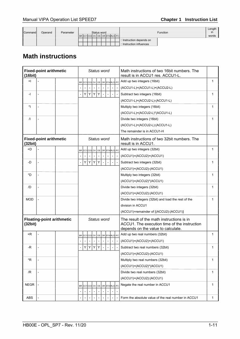
Fixed-point arithmetic (16bit)
Status word Math instructions of two 16bit numbers. The result is in ACCU1 res. ACCU1-L.
+I - BR CC1 CC0 OV OS OR STA RLO /FC Add up two integers (16bit) 1
- - - - - - - - - (ACCU1-L)=(ACCU1-L)+(ACCU2-L)
-I - - Y Y Y Y - - - - Subtract two integers (16bit) 1
(ACCU1-L)=(ACCU2-L)-(ACCU1-L)
*I - Multiply two integers (16bit) 1
(ACCU1-L)=(ACCU2-L)*(ACCU1-L)
/I - Divide two integers (16bit) 1
(ACCU1-L)=(ACCU2-L):(ACCU1-L)
The remainder is in ACCU1-H
Fixed-point arithmetic (32bit)
Status word Math instructions of two 32bit numbers. The result is in ACCU1.
+D - BR CC1 CC0 OV OS OR STA RLO /FC Add up two integers (32bit) 1
- - - - - - - - - (ACCU1)=(ACCU2)+(ACCU1)
-D - - Y Y Y Y - - - - Subtract two integers (32bit) 1
(ACCU1)=(ACCU2)-(ACCU1)
*D - Multiply two integers (32bit) 1
(ACCU1)=(ACCU2)*(ACCU1)
/D - Divide two integers (32bit) 1
(ACCU1)=(ACCU2):(ACCU1)
MOD - Divide two integers (32bit) and load the rest of the 1
division in ACCU1
(ACCU1)=remainder of [(ACCU2):(ACCU1)]
Floating-point arithmetic (32bit)
Status word The result of the math instructions is in ACCU1. The execution time of the instruction depends on the value to calculate.
+R - BR CC1 CC0 OV OS OR STA RLO /FC Add up two real numbers (32bit) 1
- - - - - - - - - (ACCU1)=(ACCU2)+(ACCU1)
-R - - Y Y Y Y - - - - Subtract two real numbers (32bit) 1
(ACCU1)=(ACCU2)-(ACCU1)
*R - Multiply two real numbers (32bit) 1
(ACCU1)=(ACCU2)*(ACCU1)
/R - Divide two real numbers (32bit) 1
(ACCU1)=(ACCU2):(ACCU1)
NEGR - BR CC1 CC0 OV OS OR STA RLO /FC Negate the real number in ACCU1 1
- - - - - - - - -
ABS - - - - - - - - - - Form the absolute value of the real number in ACCU1 1

Chapter 1 Instruction List Manual VIPA Operation List SPEED7
Command
Operand
Parameter
Status word
Function
Length in
BR CC1 CC0 OV OS OR STA RLO /FC words : Instruction depends on : Instruction influences
1-12 HB00E - OPL_SP7 - Rev. 11/20
Square root an square instructions (32bit)
Status word The result of the instructions is in ACCU1. The instructions may be interrupted by alarms.
SQRT - BR CC1 CC0 OV OS OR STA RLO /FC Calculate the Square root of a real number in ACCU1 1
- - - - - - - - -
SQR - - Y Y Y Y - - - - Form the square of a real number in ACCU1 1
Logarithmic function (32bit)
Status word The result of the logarithm function is in ACCU1. The instructions may be interrupted by alarms.
LN - BR CC1 CC0 OV OS OR STA RLO /FC Calculate the natural logarithm of a real number in 1
- - - - - - - - - ACCU1
EXP - - Y Y Y Y - - - - Calculate the exponential value of a real number in ACCU1 1
on basis e (=2.71828)
Trigonometrical functions (32bit)
Status word The result of the trigonometrical function is in ACCU1. The instructions may be interrupted by alarms.
SIN1 - BR CC1 CC0 OV OS OR STA RLO /FC Calculate the sine of the real number 1
- - - - - - - - -
ASIN2 - - Y Y Y Y - - - - Calculate the arcsine of the real number 1
COS1 - Calculate the cosine of the real number 1
ACOS2 - Calculate the arccosine of the real number 1
TAN1 - Calculate the tangent of the real number 1
ATAN2 - Calculate the arctangent of the real number 1
Addition of constants Addition of integer constants to ACCU1. The condition code bits are not affected.
+ i8 Add an 8bit integer constant 1
+ i16 Add a 16bit integer constant 2
+ i32 Add a 32bit integer constant 3
Addition via address register
Adding a 16bit integer to contents of address register. The value is in the instruction or in ACCU1-L. Condition code bits are not affected
+AR1 - Add the contents of ACCU1-L to AR1 1
+AR1 m Add a pointer constant to the contents of AR1 2
+AR2 - Add the contents of ACCU1-L to those of AR2 1
+AR2 m Add pointer constant to the contents of AR2 2
1 Specify the angle in radians; the angle must be given as a floating point value in ACCU 1.
2 The result is an angle in radians.

Manual VIPA Operation List SPEED7 Chapter 1 Instruction List
Command
Operand
Parameter
Status word
Function
Length in
BR CC1 CC0 OV OS OR STA RLO /FC words : Instruction depends on : Instruction influences
HB00E - OPL_SP7 - Rev. 11/20 1-13
Block instructions
Block call instructions Status word
CALL FB r, DB r 0 ... 8191 BR CC1 CC0 OV OS OR STA RLO /FC Unconditional call of a FB, with parameter transfer
0 ... 8191 - - - - - - - - -
CALL SFB r, DB r 0 ... 8191 - - - - 0 0 1 - 0 Unconditional call of a SFB, with parameter transfer
0 ... 8191
CALL FC r Unconditional call of a function, with parameter transfer
CALL SFC r Unconditional call of a SFC, with parameter transfer
UC FB r 0 ... 8191 Unconditional call of blocks, without parameter 1/2
FC r transfer
Parameter FB/FC call via parameters
CC FB r 0 ... 8191 BR CC1 CC0 OV OS OR STA RLO /FC Conditional call of blocks, without parameter 1/2
FC r - - - - - - - Y - transfer
Parameter - - - - 0 0 1 - 0 FB/FC call via parameters
OPN DB r 0 ... 8191 BR CC1 CC0 OV OS OR STA RLO /FC Open a data block 1/2
DI r - - - - - - - - - Open a instance data block 2
Parameter - - - - - - - - - Open a data block via parameter 2
Block end instructions Status word
BE BR CC1 CC0 OV OS OR STA RLO /FC End block 1
- - - - - - - - -
BEU - - - - 0 0 1 - 0 End block unconditionally 1
BEC BR CC1 CC0 OV OS OR STA RLO /FC End block if RLO="1"
- - - - - - - Y -
- - - - Y 0 1 1 0
Exchanging shared data block an instance data block
Exchanging the two current data blocks. The current shared data block becomes the current instance data block and vice versa. The condition code bits are not affected
CDB Exchange shared data block and instant data block 1

Chapter 1 Instruction List Manual VIPA Operation List SPEED7
Command
Operand
Parameter
Status word
Function
Length in
BR CC1 CC0 OV OS OR STA RLO /FC words : Instruction depends on : Instruction influences
1-14 HB00E - OPL_SP7 - Rev. 11/20
Program display and null instruction instructions
Program display and null operation instructions
The status word is not affected.
BLD 0 ... 255 Program display instruction: 1
is treated by the CPU like a null operation instruction
NOP 0 Null operation instruction 1
1
Edge-triggered instructions
Edge-triggered instructions Status word Detection of an edge change. The current signal state of the RLO is compared with the signal state of the instruction or edge bit memory. FP detects a change in the RLO from "0" to "1" FN detects a change in the RLO from "1" to "0"
FP I/Q a.b 0.0 ... 2047.7 BR CC1 CC0 OV OS OR STA RLO /FC Detecting the positive edge in the RLO. The bit addressed 2
M a.b 0.0 ... 8191.7 - - - - - - - Y - in the instruction is the auxiliary edge bit memory 2
L a.b parameterizable - - - - - 0 Y Y 1 2
DBX a.b 0.0 ... 65535.7 2
DIX a.b 0.0 ... 65535.7 2
c [AR1,m] 2
c [AR2,m] 2
[AR1,m] 2
[AR2,m] 2
Parameter 2
FN I/Q a.b 0.0 ... 2047.7 BR CC1 CC0 OV OS OR STA RLO /FC Detecting the negative edge in the RLO. The bit addressed 2
M a.b 0.0 ... 8191.7 - - - - - - - Y - in the instruction is the auxiliary edge bit memory 2
L a.b parameterizable - - - - - 0 Y Y 1 2
DBX a.b 0.0 ... 65535.7 2
DIX a.b 0.0 ... 65535.7 2
c [AR1,m] 2
c [AR2,m] 2
[AR1,m] 2
[AR2,m] 2
Parameter 2

Manual VIPA Operation List SPEED7 Chapter 1 Instruction List
Command
Operand
Parameter
Status word
Function
Length in
BR CC1 CC0 OV OS OR STA RLO /FC words : Instruction depends on : Instruction influences
HB00E - OPL_SP7 - Rev. 11/20 1-15
Load instructions
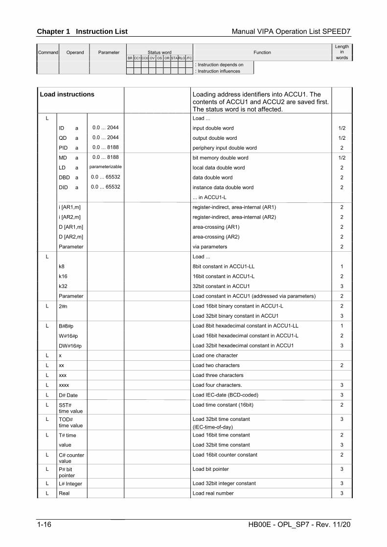
Load instructions Loading address identifiers into ACCU1. The contents of ACCU1 and ACCU2 are saved first.The status word is not affected.
L Load ...
IB a 0.0 ... 2047 input byte 1/2
QB a 0.0 ... 2047 output byte 1/2
PIB a 0.0 ... 8191 periphery input byte 2
MB a 0.0 ... 8191 bit memory byte 1/2
LB a parameterizable local data byte 2
DBB a 0.0 ... 65535 data byte 2
DIB a 0.0 ... 65535 instance data byte 2
... in ACCU1 2
g [AR1,m] register-indirect, area-internal (AR1) 2
g [AR2,m] register-indirect, area-internal (AR2) 2
B [AR1,m] area-crossing (AR1) 2
B [AR2,m] area-crossing (AR2) 2
Parameter via parameters 2
L Load ...
IW a 0.0 ... 2046 input word 1/2
QW a 0.0 ... 2046 output word 1/2
PIW a 0.0 ... 8190 periphery input word
MW a 0.0 ... 8190 bit memory word 1/2
LW a parameterizable local data word 2
DBW a 0.0 ... 65534 data word 1/2
DIW a 0.0 ... 65534 instance data word 1/2
... in ACCU1-L
h [AR1,m] register-indirect, area-internal (AR1) 2
h [AR2,m] register-indirect, area-internal (AR2) 2
W [AR1,m] area-crossing (AR1) 2
W [AR2,m] area-crossing (AR2) 2
Parameter via parameters 2
Chapter 1 Instruction List Manual VIPA Operation List SPEED7
Command
Operand
Parameter
Status word
Function
Length in
BR CC1 CC0 OV OS OR STA RLO /FC words : Instruction depends on : Instruction influences
1-16 HB00E - OPL_SP7 - Rev. 11/20
Load instructions Loading address identifiers into ACCU1. The contents of ACCU1 and ACCU2 are saved first.The status word is not affected.
L Load ...
ID a 0.0 ... 2044 input double word 1/2
QD a 0.0 ... 2044 output double word 1/2
PID a 0.0 ... 8188 periphery input double word 2
MD a 0.0 ... 8188 bit memory double word 1/2
LD a parameterizable local data double word 2
DBD a 0.0 ... 65532 data double word 2
DID a 0.0 ... 65532 instance data double word 2
... in ACCU1-L
i [AR1,m] register-indirect, area-internal (AR1) 2
i [AR2,m] register-indirect, area-internal (AR2) 2
D [AR1,m] area-crossing (AR1) 2
D [AR2,m] area-crossing (AR2) 2
Parameter via parameters 2
L Load ...
k8 8bit constant in ACCU1-LL 1
k16 16bit constant in ACCU1-L 2
k32 32bit constant in ACCU1 3
Parameter Load constant in ACCU1 (addressed via parameters) 2
L 2#n Load 16bit binary constant in ACCU1-L 2
Load 32bit binary constant in ACCU1 3
L B#8#p Load 8bit hexadecimal constant in ACCU1-LL 1
W#16#p Load 16bit hexadecimal constant in ACCU1-L 2
DW#16#p Load 32bit hexadecimal constant in ACCU1 3
L x Load one character
L xx Load two characters 2
L xxx Load three characters
L xxxx Load four characters. 3
L D# Date Load IEC-date (BCD-coded) 3
L S5T# time value
Load time constant (16bit) 2
L TOD# time value
Load 32bit time constant (IEC-time-of-day)
3
L T# time Load 16bit time constant 2
value Load 32bit time constant 3
L C# counter value
Load 16bit counter constant 2
L P# bit pointer
Load bit pointer 3
L L# Integer Load 32bit integer constant 3
L Real Load real number 3

Manual VIPA Operation List SPEED7 Chapter 1 Instruction List
Command
Operand
Parameter
Status word
Function
Length in
BR CC1 CC0 OV OS OR STA RLO /FC words : Instruction depends on : Instruction influences
HB00E - OPL_SP7 - Rev. 11/20 1-17
Load instructions for timer and counter
Load a time or counter value in ACCU1, before the recent content of ACCU1 is saved in ACCU2. The status word is not affected.
L T f 0 ... 511 Load time value 1/2
Timer p. Load time value (addressed via parameters) 2
L C f 0 ... 511 Load counter value 1/2
Counter p. Load counter value (addressed via parameters) 2
LD T f 0 ... 511 Load time value BCD-coded 1/2
Timer p. Load time value BCD-coded (addressed via parameters) 2
LD C f 0 ... 511 Load counter value BCD-coded 1/2
Counter p. Load counter value BCD-coded (addressed via parameters)
2
Chapter 1 Instruction List Manual VIPA Operation List SPEED7
Command
Operand
Parameter
Status word
Function
Length in
BR CC1 CC0 OV OS OR STA RLO /FC words : Instruction depends on : Instruction influences
1-18 HB00E - OPL_SP7 - Rev. 11/20
Shift instructions
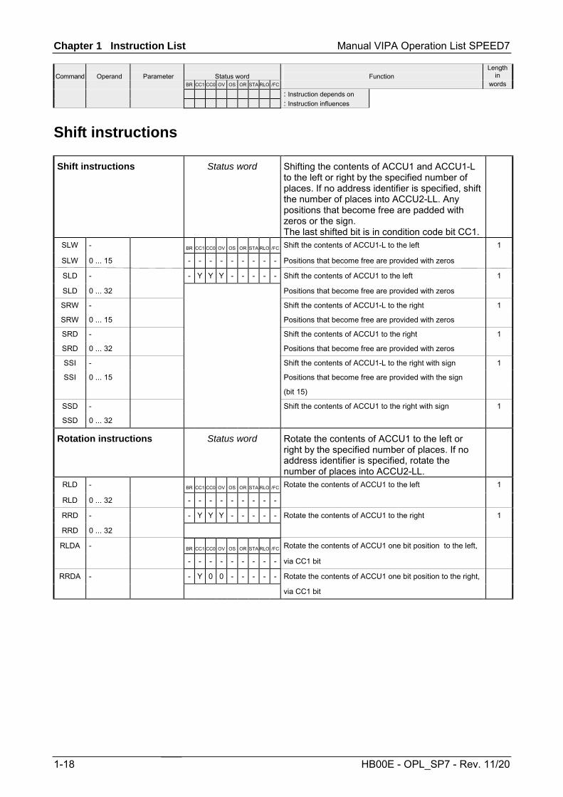
Shift instructions Status word Shifting the contents of ACCU1 and ACCU1-L to the left or right by the specified number of places. If no address identifier is specified, shift the number of places into ACCU2-LL. Any positions that become free are padded with zeros or the sign. The last shifted bit is in condition code bit CC1.
SLW - BR CC1 CC0 OV OS OR STA RLO /FC Shift the contents of ACCU1-L to the left 1
SLW 0 ... 15 - - - - - - - - - Positions that become free are provided with zeros
SLD - - Y Y Y - - - - - Shift the contents of ACCU1 to the left 1
SLD 0 ... 32 Positions that become free are provided with zeros
SRW - Shift the contents of ACCU1-L to the right 1
SRW 0 ... 15 Positions that become free are provided with zeros
SRD - Shift the contents of ACCU1 to the right 1
SRD 0 ... 32 Positions that become free are provided with zeros
SSI - Shift the contents of ACCU1-L to the right with sign 1
SSI 0 ... 15 Positions that become free are provided with the sign
(bit 15)
SSD - Shift the contents of ACCU1 to the right with sign 1
SSD 0 ... 32
Rotation instructions Status word Rotate the contents of ACCU1 to the left or right by the specified number of places. If no address identifier is specified, rotate the number of places into ACCU2-LL.
RLD - BR CC1 CC0 OV OS OR STA RLO /FC Rotate the contents of ACCU1 to the left 1
RLD 0 ... 32 - - - - - - - - -
RRD - - Y Y Y - - - - - Rotate the contents of ACCU1 to the right 1
RRD 0 ... 32
RLDA - BR CC1 CC0 OV OS OR STA RLO /FC Rotate the contents of ACCU1 one bit position to the left,
- - - - - - - - - via CC1 bit
RRDA - - Y 0 0 - - - - - Rotate the contents of ACCU1 one bit position to the right,
via CC1 bit

Manual VIPA Operation List SPEED7 Chapter 1 Instruction List
Command
Operand
Parameter
Status word
Function
Length in
BR CC1 CC0 OV OS OR STA RLO /FC words : Instruction depends on : Instruction influences
HB00E - OPL_SP7 - Rev. 11/20 1-19
Setting/resetting bit addresses
Set/Reset bit addresses Status word Assign the value "1" or "0" or the RLO to the addressed instructions.
S BR CC1 CC0 OV OS OR STA RLO /FC Set ...
I/Q a.b 0.0 ... 2047.7 - - - - - - - Y - input/output to "1" 1/2
M a.b 0.0 ... 8191.7 - - - - - 0 Y - 0 set bit memory to "1" 1/2
L a.b parameterizable local data bit to "1" 2
DBX a.b 0.0 ... 65535.7 data bit to "1" 2
DIX a.b 0.0 ... 65535.7 instance data bit to "1" 2
c [AR1,m] register-indirect, area-internal (AR1) 2
c [AR2,m] register-indirect, area-internal (AR2) 2
[AR1,m] area-crossing (AR1) 2
[AR2,m] area-crossing (AR2) 2
Parameter via parameters 2
R BR CC1 CC0 OV OS OR STA RLO /FC Reset ...
I/Q a.b 0.0 ... 2047.7 - - - - - - - Y - input/output to "0" 1/2
M a.b 0.0 ... 8191.7 - - - - - 0 Y - 0 set bit memory to "0" 1/2
L a.b parameterizable local data bit to "0" 2
DBX a.b 0.0 ... 65535.7 data bit to "0" 2
DIX a.b 0.0 ... 65535.7 instance data bit to "0" 2
c [AR1,m] register-indirect, area-internal (AR1) 2
c [AR2,m] register-indirect, area-internal (AR2) 2
W [AR1,m] area-crossing (AR1) 2
W [AR2,m] area-crossing (AR2) 2
Parameter via parameters 2
= BR CC1 CC0 OV OS OR STA RLO /FC Assign ...
I/Q a.b 0.0 ... 2047.7 - - - - - - - Y - RLO to input/output 1/2
M a.b 0.0 ... 8191.7 - - - - - 0 Y - 0 RLO to bit memory 1/2
L a.b parameterizable RLO to local data bit 2
DBX a.b 0.0 ... 65535.7 RLO to data bit 2
DIX a.b 0.0 ... 65535.7 RLO to instance data bit 2
c [AR1,m] register-indirect, area-internal (AR1) 2
c [AR2,m] register-indirect, area-internal (AR2) 2
[AR1,m] area-crossing (AR1) 2
[AR2,m] area-crossing (AR2) 2
Parameter via parameters 2

Chapter 1 Instruction List Manual VIPA Operation List SPEED7
Command
Operand
Parameter
Status word
Function
Length in
BR CC1 CC0 OV OS OR STA RLO /FC words : Instruction depends on : Instruction influences
1-20 HB00E - OPL_SP7 - Rev. 11/20
Instructions directly affecting the RLO
Status word The following instructions have a directly effect on the RLO.
CLR BR CC1 CC0 OV OS OR STA RLO /FC Set RLO to "0" 1
- - - - - - - - -
- - - - - 0 0 0 0
SET BR CC1 CC0 OV OS OR STA RLO /FC Set RLO to "1" 1
- - - - - - - - -
- - - - - 0 1 1 0
NOT BR CC1 CC0 OV OS OR STA RLO /FC Negate RLO 1
- - - - - Y - Y -
- - - - - - 1 Y -
SAVE BR CC1 CC0 OV OS OR STA RLO /FC Save RLO into BR-bit 1
- - - - - - - Y -
Y - - - - - - - -

Manual VIPA Operation List SPEED7 Chapter 1 Instruction List
Command
Operand
Parameter
Status word
Function
Length in
BR CC1 CC0 OV OS OR STA RLO /FC words : Instruction depends on : Instruction influences
HB00E - OPL_SP7 - Rev. 11/20 1-21
Jump instructions
Jump instructions Status word Jump, depending on conditions. 8-bit operands have a jump width of (-128...+127), 16-bit operands of (-32768...-129) or (+128...+32767)
JU LABEL BR CC1 CC0 OV OS OR STA RLO /FC Jump unconditionally 1/2
- - - - - - - - -
- - - - - - - - -
JC LABEL BR CC1 CC0 OV OS OR STA RLO /FC Jump if RLO="1" 1/2
JCN LABEL - - - - - - - Y - Jump if RLO="0" 2
- - - - - 0 1 1 0
JCB LABEL BR CC1 CC0 OV OS OR STA RLO /FC Jump if RLO="1" 2
- - - - - - - Y - Save the RLO in the BR-bit
JNB LABEL Y - - - - 0 1 1 0 Jump if RLO="0" 2
Save the RLO in the BR-bit
JBI LABEL BR CC1 CC0 OV OS OR STA RLO /FC Jump if BR="1" 2
JNBI LABEL Y - - - - - - - - Jump if BR="0" 2
- - - - - 0 1 - 0
JO LABEL BR CC1 CC0 OV OS OR STA RLO /FC Jump on stored overflow (OV="1") 1/2
- - - Y - - - - -
- - - - - - - - -
JOS LABEL BR CC1 CC0 OV OS OR STA RLO /FC Jump on stored overflow (OS="1") 2
- - - - Y - - - -
- - - - 0 - - - -
JUO LABEL BR CC1 CC0 OV OS OR STA RLO /FC Jump if "unordered instruction" (CC1=1 and CC0=1)
JZ LABEL - Y Y - - - - - - Jump if result=0 (CC1=0 and CC0=0) 1/2
JP LABEL - - - - - - - - - Jump if result>0 (CC1=1 and CC0=0) 1/2
JM LABEL Jump if result<0 (CC1=0 and CC0=1) 1/2
JN LABEL Jump if result≠0 1/2
(CC1=1 and CC0=0) or (CC1=0) and (CC0=1)
JMZ LABEL Jump if result≤0 2
(CC1=0 and CC0=1) or (CC1=0 and CC0=0)
JPZ LABEL Jump if result≥0 2
(CC1=1 and CC0=0) or (CC1=0 and CC0=0)
JL LABEL BR CC1 CC0 OV OS OR STA RLO /FC Jump distributor 2
- - - - - - - - - This instruction is followed by a list of jump instructions
- - - - - - - - - The operand is a jump label to subsequent instructions in
this list. ACCU1-L contains the number of the jump instruction to be executed
LOOP LABEL Decrement ACCU1-L and jump if ACCU1-L _ 0 (loop programming)
2

Chapter 1 Instruction List Manual VIPA Operation List SPEED7
Command
Operand
Parameter
Status word
Function
Length in
BR CC1 CC0 OV OS OR STA RLO /FC words : Instruction depends on : Instruction influences
1-22 HB00E - OPL_SP7 - Rev. 11/20
Transfer instructions
Transfer instructions Transfer the contents of ACCU1 into the addressed operand. The status word is not affected.
T Transfer the contents of ACCU1-LL to ...
IB a 0.0 ... 2047 input byte 1/2
QB a 0.0 ... 2047 output byte 1/2
PQB a 0.0 ... 8191 periphery output byte 1/2
MB a 0.0 ... 8191 bit memory byte 1/2
LB a parameterizable local data byte 2
DBB a 0.0 ... 65535 data byte 2
DIB a 0.0 ... 65535 instance data byte 2
g [AR1,m] register-indirect, area-internal (AR1) 2
g [AR2,m] register-indirect, area-internal (AR2) 2
B [AR1,m] area-crossing (AR1) 2
B [AR2,m] area-crossing (AR2) 2
Parameter via parameters 2
T Transfer the contents of ACCU1-L to ...
IW 0.0 ... 2046 input word 1/2
QW 0.0 ... 2046 output word 1/2
PQW 0.0 ... 8190 periphery output word 1/2
MW 0.0 ... 8190 bit memory word 1/2
LW parameterizable local data word 2
DBW 0.0 ... 65534 data word 2
DIW 0.0 ... 65534 instance data word 2
h [AR1,m] register-indirect, area-internal (AR1) 2
h [AR2,m] register-indirect, area-internal (AR2) 2
W [AR1,m] area-crossing (AR1) 2
W [AR2,m] area-crossing (AR2) 2
Parameter via parameters 2

Manual VIPA Operation List SPEED7 Chapter 1 Instruction List
Command
Operand
Parameter
Status word
Function
Length in
BR CC1 CC0 OV OS OR STA RLO /FC words : Instruction depends on : Instruction influences
HB00E - OPL_SP7 - Rev. 11/20 1-23
Transfer instructions Transfer the contents of ACCU1 into the addressed operand. The status word is not affected.
T Transfer the contents of ACCU1 to ...
ID 0.0 ... 2044 input double word 1/2
QD 0.0 ... 2044 output double word 1/2
PQD 0.0 ... 8188 periphery output double word 1/2
MD 0.0 ... 8188 bit memory double word 1/2
LD parameterizable local data double word 2
DBD 0.0 ... 65532 data double word 2
DID 0.0 ... 65532 instance data double word 2
i [AR1,m] register-indirect, area-internal (AR1) 2
i [AR2,m] register-indirect, area-internal (AR2) 2
D [AR1,m] area-crossing (AR1) 2
D [AR2,m] area-crossing (AR2) 2
Parameter via parameters 2
Load and transfer instructions for address register
Load a double word from a memory area or a register into AR1 or AR2.
LAR1 Load the contents from ...
- ACCU1 1
AR2 address register 2 1
DBD a 0 ... 65532 data double word 2
DID a 0 ... 65532 instance data double word 2
m 32bit constant as pointer 3
LD a parameterizable local data double word 2
MD a 0 ... 8188 bit memory double word 2
... into AR1
LAR2 Load the contents from ...
- ACCU1 1
DBD a 0 ... 65532 data double word 2
DID a 0 ... 65532 instance data double word 2
m 32bit constant as pointer 3
LD a parameterizable local data double word 2
MD a 0 ... 8188 bit memory double word 2
... into AR2
TAR1 Transfer the contents from AR1 to ...
- ACCU1 1
AR2 address register 2 1
DBD a 0 ... 65532 data double word 2
DID a 0 ... 65532 instance data double word 2
LD a parameterizable local data double word 2
MD a 0 ... 8188 bit memory double word 2
Chapter 1 Instruction List Manual VIPA Operation List SPEED7
Command
Operand
Parameter
Status word
Function
Length in
BR CC1 CC0 OV OS OR STA RLO /FC words : Instruction depends on : Instruction influences
1-24 HB00E - OPL_SP7 - Rev. 11/20
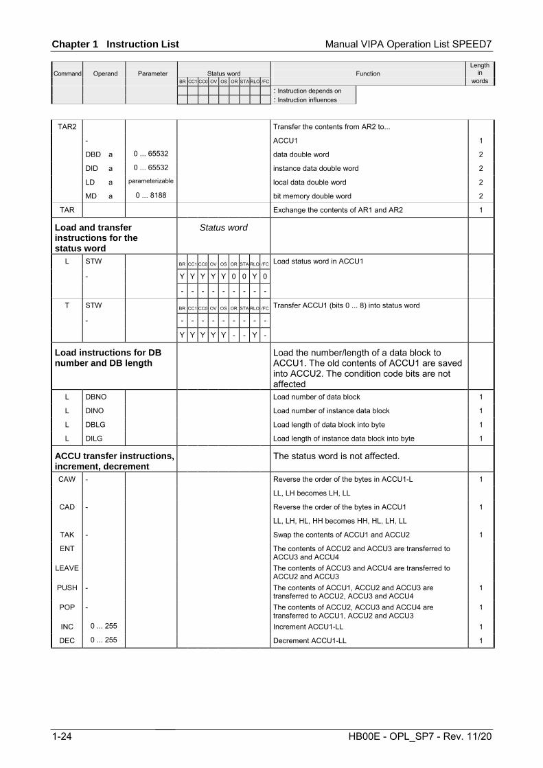
TAR2 Transfer the contents from AR2 to...
- ACCU1 1
DBD a 0 ... 65532 data double word 2
DID a 0 ... 65532 instance data double word 2
LD a parameterizable local data double word 2
MD a 0 ... 8188 bit memory double word 2
TAR Exchange the contents of AR1 and AR2 1
Load and transfer instructions for the status word
Status word
L STW BR CC1 CC0 OV OS OR STA RLO /FC Load status word in ACCU1
- Y Y Y Y Y 0 0 Y 0
- - - - - - - - -
T STW BR CC1 CC0 OV OS OR STA RLO /FC Transfer ACCU1 (bits 0 ... 8) into status word
- - - - - - - - - -
Y Y Y Y Y - - Y -
Load instructions for DB number and DB length
Load the number/length of a data block to ACCU1. The old contents of ACCU1 are saved into ACCU2. The condition code bits are not affected
L DBNO Load number of data block 1
L DINO Load number of instance data block 1
L DBLG Load length of data block into byte 1
L DILG Load length of instance data block into byte 1
ACCU transfer instructions, increment, decrement
The status word is not affected.
CAW - Reverse the order of the bytes in ACCU1-L 1
LL, LH becomes LH, LL
CAD - Reverse the order of the bytes in ACCU1 1
LL, LH, HL, HH becomes HH, HL, LH, LL
TAK - Swap the contents of ACCU1 and ACCU2 1
ENT The contents of ACCU2 and ACCU3 are transferred to ACCU3 and ACCU4
LEAVE The contents of ACCU3 and ACCU4 are transferred to ACCU2 and ACCU3
PUSH - The contents of ACCU1, ACCU2 and ACCU3 are transferred to ACCU2, ACCU3 and ACCU4
1
POP - The contents of ACCU2, ACCU3 and ACCU4 are transferred to ACCU1, ACCU2 and ACCU3
1
INC 0 ... 255 Increment ACCU1-LL 1
DEC 0 ... 255 Decrement ACCU1-LL 1

Manual VIPA Operation List SPEED7 Chapter 1 Instruction List
Command
Operand
Parameter
Status word
Function
Length in
BR CC1 CC0 OV OS OR STA RLO /FC words : Instruction depends on : Instruction influences
HB00E - OPL_SP7 - Rev. 11/20 1-25
Data type conversion instructions
Data type conversion instructions
Status word The results of the conversion are in ACCU1. When converting real numbers, the execution time depends on the value.
BTI - BR CC1 CC0 OV OS OR STA RLO /FC Convert contents of ACCU1 from BCD to integer (16bit) 1
- - - - - - - - - (BCD To Int.)
BTD - - - - - - - - - - Convert contents of ACCU1 from BCD to integer (32bit). 1
(BCD To Doubleint.)
DTR - Convert cont. of ACCU1 from integer (32bit) to Real number 1
(32bit) (Doubleint. To Real)
ITD - Convert contents of ACCU1 from integer (16bit) to integer 1
(32bit) (Int. To Doubleint)
ITB - BR CC1 CC0 OV OS OR STA RLO /FC Convert contents of ACCU1 from integer (16bit) to BCD 1
- - - - - - - - - 0 ... +/-999 (Int. To BCD)
DTB - - - - Y Y - - - - Convert contents of ACCU1 from integer (32bit) to BCD 1
0 ... +/-9 999 999 (Doubleint. To BCD)
RND - BR CC1 CC0 OV OS OR STA RLO /FC Convert a real number to 32bit integer 1
RND- - - - - - - - - - - Convert a real number to 32bit integer 1
- - - Y Y - - - - The number is rounded next hole number
RND+ - Convert real number to 32bit integer 1
It is rounded up to the next integer
TRUNC - Convert real number to 32bit integer 1
The places after the decimal point are truncated
Complement creation Status word
INVI - BR CC1 CC0 OV OS OR STA RLO /FC Forms the ones complement of ACCU1-L 1
INVD - - - - - - - - - - Forms the ones complement of ACCU1 1
- - - - - - - - -
NEGI - BR CC1 CC0 OV OS OR STA RLO /FC Forms the twos complement of ACCU1-L (integer) 1
NEGD - - - - - - - - - - Forms the twos complement of ACCU1 (double integer) 1
- Y Y Y Y - - - -
Chapter 1 Instruction List Manual VIPA Operation List SPEED7
Command
Operand
Parameter
Status word
Function
Length in
BR CC1 CC0 OV OS OR STA RLO /FC words : Instruction depends on : Instruction influences
1-26 HB00E - OPL_SP7 - Rev. 11/20
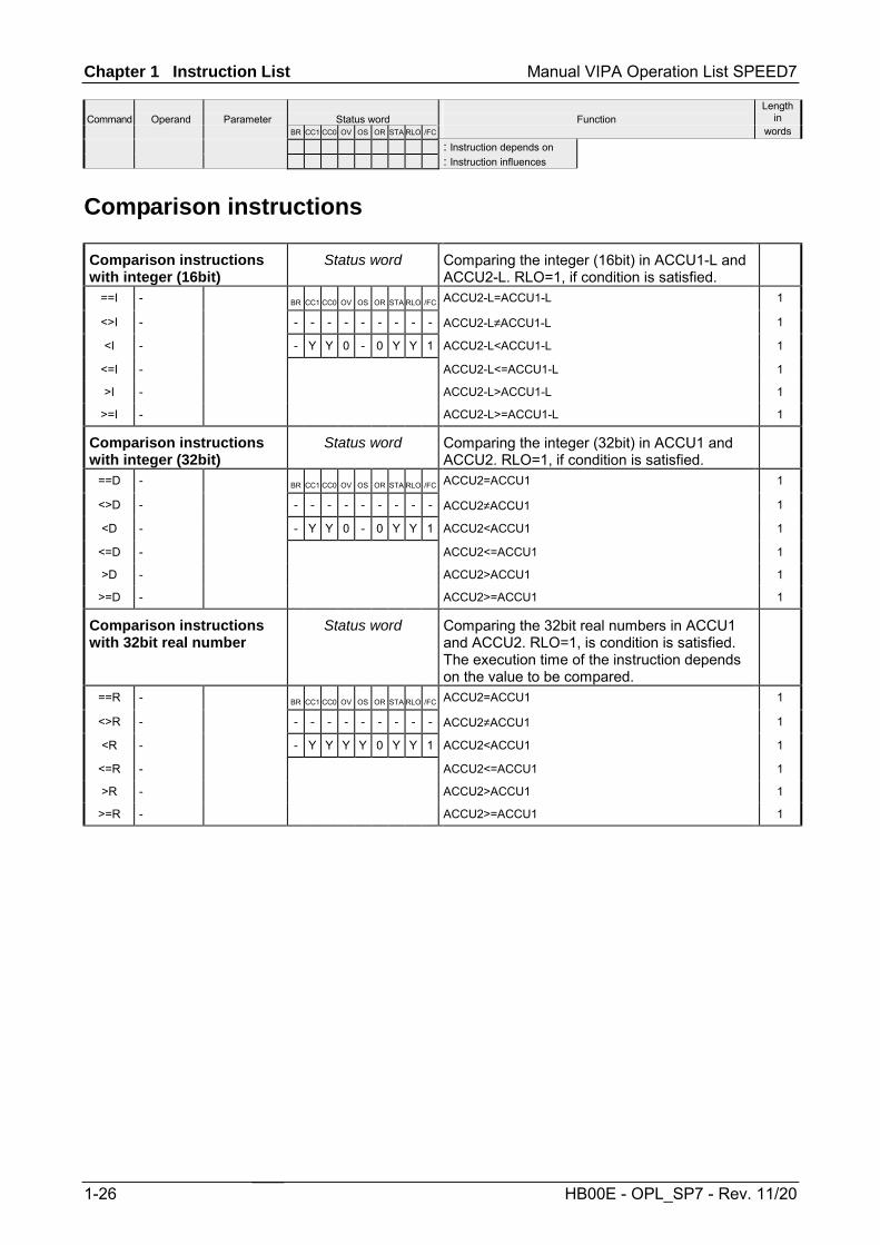
Comparison instructions
Comparison instructions with integer (16bit)
Status word Comparing the integer (16bit) in ACCU1-L and ACCU2-L. RLO=1, if condition is satisfied.
==I - BR CC1 CC0 OV OS OR STA RLO /FC ACCU2-L=ACCU1-L 1
<>I - - - - - - - - - - ACCU2-L≠ACCU1-L 1
<I - - Y Y 0 - 0 Y Y 1 ACCU2-L<ACCU1-L 1
<=I - ACCU2-L<=ACCU1-L 1
>I - ACCU2-L>ACCU1-L 1
>=I - ACCU2-L>=ACCU1-L 1
Comparison instructions with integer (32bit)
Status word Comparing the integer (32bit) in ACCU1 and ACCU2. RLO=1, if condition is satisfied.
==D - BR CC1 CC0 OV OS OR STA RLO /FC ACCU2=ACCU1 1
<>D - - - - - - - - - - ACCU2≠ACCU1 1
<D - - Y Y 0 - 0 Y Y 1 ACCU2<ACCU1 1
<=D - ACCU2<=ACCU1 1
>D - ACCU2>ACCU1 1
>=D - ACCU2>=ACCU1 1
Comparison instructions with 32bit real number
Status word Comparing the 32bit real numbers in ACCU1 and ACCU2. RLO=1, is condition is satisfied. The execution time of the instruction depends on the value to be compared.
==R - BR CC1 CC0 OV OS OR STA RLO /FC ACCU2=ACCU1 1
<>R - - - - - - - - - - ACCU2≠ACCU1 1
<R - - Y Y Y Y 0 Y Y 1 ACCU2<ACCU1 1
<=R - ACCU2<=ACCU1 1
>R - ACCU2>ACCU1 1
>=R - ACCU2>=ACCU1 1
Manual VIPA Operation List SPEED7 Chapter 1 Instruction List
Command
Operand
Parameter
Status word
Function
Length in
BR CC1 CC0 OV OS OR STA RLO /FC words : Instruction depends on : Instruction influences
HB00E - OPL_SP7 - Rev. 11/20 1-27
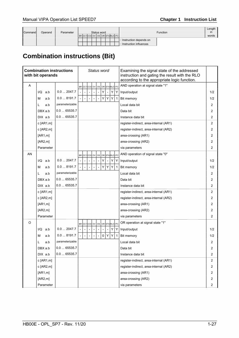
Combination instructions (Bit)
Combination instructions with bit operands
Status word Examining the signal state of the addressed instruction and gating the result with the RLO according to the appropriate logic function.
A BR CC1 CC0 OV OS OR STA RLO /FC AND operation at signal state "1"
I/Q a.b 0.0 ... 2047.7 - - - - - Y - Y Y Input/output 1/2
M a.b 0.0 ... 8191.7 - - - - - Y Y Y 1 Bit memory 1/2
L a.b parameterizable Local data bit 2
DBX a.b 0.0 ... 65535.7 Data bit 2
DIX a.b 0.0 ... 65535.7 Instance data bit 2
c [AR1,m] register-indirect, area-internal (AR1) 2
c [AR2,m] register-indirect, area-internal (AR2) 2
[AR1,m] area-crossing (AR1) 2
[AR2,m] area-crossing (AR2) 2
Parameter via parameters 2
AN BR CC1 CC0 OV OS OR STA RLO /FC AND operation of signal state "0"
I/Q a.b 0.0 ... 2047.7 - - - - - Y - Y Y Input/output 1/2
M a.b 0.0 ... 8191.7 - - - - - Y Y Y 1 Bit memory 1/2
L a.b parameterizable Local data bit 2
DBX a.b 0.0 ... 65535.7 Data bit 2
DIX a.b 0.0 ... 65535.7 Instance data bit 2
c [AR1,m] register-indirect, area-internal (AR1) 2
c [AR2,m] register-indirect, area-internal (AR2) 2
[AR1,m] area-crossing (AR1) 2
[AR2,m] area-crossing (AR2) 2
Parameter via parameters 2
O BR CC1 CC0 OV OS OR STA RLO /FC OR operation at signal state "1"
I/Q a.b 0.0 ... 2047.7 - - - - - - - Y Y Input/output 1/2
M a.b 0.0 ... 8191.7 - - - - - 0 Y Y 1 Bit memory 1/2
L a.b parameterizable Local data bit 2
DBX a.b 0.0 ... 65535.7 Data bit 2
DIX a.b 0.0 ... 65535.7 Instance data bit 2
c [AR1,m] register-indirect, area-internal (AR1) 2
c [AR2,m] register-indirect, area-internal (AR2) 2
[AR1,m] area-crossing (AR1) 2
[AR2,m] area-crossing (AR2) 2
Parameter via parameters 2

Chapter 1 Instruction List Manual VIPA Operation List SPEED7
Command
Operand
Parameter
Status word
Function
Length in
BR CC1 CC0 OV OS OR STA RLO /FC words : Instruction depends on : Instruction influences
1-28 HB00E - OPL_SP7 - Rev. 11/20
Combination instructions with bit operands
Status word Examining the signal state of the addressed instruction and gating the result with the RLO according to the appropriate logic function.
ON BR CC1 CC0 OV OS OR STA RLO /FC OR operation at signal state "0"
I/Q a.b 0.0 ... 2047.7 - - - - - - - Y Y Input/output 1/2
M a.b 0.0 ... 8191.7 - - - - - 0 Y Y 1 Bit memory 1/2
L a.b parameterizable Local data bit 2
DBX a.b 0.0 ... 65535.7 Data bit 2
DIX a.b 0.0 ... 65535.7 Instance data bit 2
c [AR1,m] register-indirect, area-internal (AR1) 2
c [AR2,m] register-indirect, area-internal (AR2) 2
[AR1,m] area-crossing (AR1) 2
[AR2,m] area-crossing (AR2) 2
Parameter via parameters 2
X BR CC1 CC0 OV OS OR STA RLO /FC EXCLUSIVE-OR operation at signal state "1"
I/Q a.b 0.0 ... 2047.7 - - - - - - - Y Y Input/output 2
M a.b 0.0 ... 8191.7 - - - - - 0 Y Y 1 Bit memory 2
L a.b parameterizable Local data bit 2
DBX a.b 0.0 ... 65535.7 data bit 2
DIX a.b 0.0 ... 65535.7 Instance data bit 2
c [AR1,m] register-indirect, area-internal (AR1) 2
c [AR2,m] register-indirect, area-internal (AR2) 2
[AR1,m] area-crossing (AR1) 2
[AR2,m] area-crossing (AR2) 2
Parameter via parameters 2
XN BR CC1 CC0 OV OS OR STA RLO /FC EXCLUSIVE-OR operation at signal state "0"
I/Q a.b 0.0 ... 2047.7 - - - - - - - Y Y Input/output 2
M a.b 0.0 ... 8191.7 - - - - - 0 Y Y 1 Bit memory 2
L a.b parameterizable Local data bit 2
DBX a.b 0.0 ... 65535.7 Data bit 2
DIX a.b 0.0 ... 65535.7 Instance data bit 2
c [AR1,m] register-indirect, area-internal (AR1) 2
c [AR2,m] register-indirect, area-internal (AR2) 2
[AR1,m] area-crossing (AR1) 2
[AR2,m] area-crossing (AR2) 2
Parameter via parameters 2

Manual VIPA Operation List SPEED7 Chapter 1 Instruction List
Command
Operand
Parameter
Status word
Function
Length in
BR CC1 CC0 OV OS OR STA RLO /FC words : Instruction depends on : Instruction influences
HB00E - OPL_SP7 - Rev. 11/20 1-29
Combination instructions with parenthetical expressions
Status word Saving the bits BR, RLO, OR and a function ID (A, AN, ...) at the nesting stack. For each block 7 nesting levels are possible.
A( BR CC1 CC0 OV OS OR STA RLO /FC AND left parenthesis 1
AN( Y - - - - Y - Y Y AND-NOT left parenthesis 1
O( - - - - - 0 1 - 0 OR left parenthesis 1
ON( OR-NOT left parenthesis 1
X( EXCLUSIVE-OR left parenthesis 1
XN( EXCLUSIVE-OR-NOT left parenthesis 1
) BR CC1 CC0 OV OS OR STA RLO /FC Right parenthesis, popping an entry off the nesting stack, 1
- - - - - - - Y - gating RLO with the current RLO in the processor
Y - - - - Y 1 Y 1
ORing of AND operations Status word The ORing of AND operations is implemented according the rule: AND before OR.
O BR CC1 CC0 OV OS OR STA RLO /FC OR operations of AND functions according the rule: 1
- - - - - Y - Y Y AND before OR
- - - - - Y 1 - Y

Chapter 1 Instruction List Manual VIPA Operation List SPEED7
Command
Operand
Parameter
Status word
Function
Length in
BR CC1 CC0 OV OS OR STA RLO /FC words : Instruction depends on : Instruction influences
1-30 HB00E - OPL_SP7 - Rev. 11/20
Combination instructions with timer and counters
Status word Examining the signal state of the addressed timer/counter an gating the result with the RLO according to the appropriate logic function.
A BR CC1 CC0 OV OS OR STA RLO /FC AND operation at signal state
T f 0 ... 511 - - - - - Y - Y Y Timer 1/2
C f 0 ... 511 - - - - - Y Y Y 1 Counter 1/2
Timer p. Timer addressed via parameters 2
Counter p. Counter addressed via parameters
AN BR CC1 CC0 OV OS OR STA RLO /FC AND operation at signal state
T f 0 ... 511 - - - - - Y - Y Y Timer 1/2
C f 0 ... 511 - - - - - Y Y Y 1 Counter 1/2
Timer p. Timer addressed via parameters 2
Counter p. Counter addressed via parameters
O BR CC1 CC0 OV OS OR STA RLO /FC OR operation at signal state
T f 0 ... 511 - - - - - - - Y Y Timer 1/2
C f 0 ... 511 - - - - - 0 Y Y 1 Counter 1/2
Timer p. Timer addressed via parameters 2
Counter p. Counter addressed via parameters
ON BR CC1 CC0 OV OS OR STA RLO /FC OR operation at signal state
T f 0 ... 511 - - - - - - - Y Y Timer 1/2
C f 0 ... 511 - - - - - 0 Y Y 1 Counter 1/2
Timer p. Timer addressed via parameters 2
Counter p. Counter addressed via parameters
X BR CC1 CC0 OV OS OR STA RLO /FC EXCLUSIVE-OR operation at signal state
T f 0 ... 511 - - - - - - - Y Y Timer 2
C f 0 ... 511 - - - - - 0 Y Y 1 Counter 2
Timer p. Timer addressed via parameters 2
Counter p. Counter addressed via parameters
XN BR CC1 CC0 OV OS OR STA RLO /FC EXCLUSIVE-OR operation at signal state
T f 0 ... 511 - - - - - - - Y Y Timer 2
C f 0 ... 511 - - - - - 0 Y Y 1 Counter 2
Timer p. Timer addressed via parameters 2
Counter p. Counter addressed via parameters
Manual VIPA Operation List SPEED7 Chapter 1 Instruction List
Command
Operand
Parameter
Status word
Function
Length in
BR CC1 CC0 OV OS OR STA RLO /FC words : Instruction depends on : Instruction influences
HB00E - OPL_SP7 - Rev. 11/20 1-31
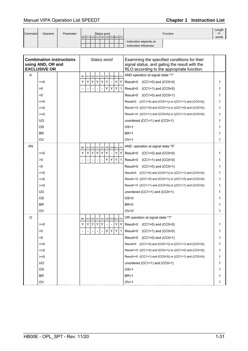
Combination instructions using AND, OR and EXCLUSIVE OR
Status word Examining the specified conditions for their signal status, and gating the result with the RLO according to the appropriate function.
A BR CC1 CC0 OV OS OR STA RLO /FC AND operation at signal state "1"
==0 Y Y Y Y Y Y - Y Y Result=0 (CC1=0) and (CC0=0) 1
>0 - - - - - Y Y Y 1 Result>0 (CC1=1) and (CC0=0) 1
<0 Result<0 (CC1=0) and (CC0=1) 1
<>0 Result≠0 ((CC1=0) and (CC0=1)) or ((CC1=1) and (CC0=0)) 1
<=0 Result<=0 ((CC1=0) and (CC0=1)) or ((CC1=0) and (CC0=0)) 1
>=0 Result>=0 ((CC1=1) and (CC0=0)) or ((CC1=1) and (CC0=0)) 1
UO unordered (CC1=1) and (CC0=1) 1
OS OS=1 1
BR BR=1 1
OV OV=1 1
AN BR CC1 CC0 OV OS OR STA RLO /FC AND operation at signal state "0"
==0 Y Y Y Y Y Y - Y Y Result=0 (CC1=0) and (CC0=0) 1
>0 - - - - - Y Y Y 1 Result>0 (CC1=1) and (CC0=0) 1
<0 Result<0 (CC1=0) and (CC0=1) 1
<>0 Result≠0 ((CC1=0) and (CC0=1)) or ((CC1=1) and (CC0=0)) 1
<=0 Result<=0 ((CC1=0) and (CC0=1)) or ((CC1=0) and (CC0=0)) 1
>=0 Result>=0 ((CC1=1) and (CC0=0)) or ((CC1=1) and (CC0=0)) 1
UO unordered (CC1=1) and (CC0=1) 1
OS OS=0 1
BR BR=0 1
OV OV=0 1
O BR CC1 CC0 OV OS OR STA RLO /FC OR operation at signal state "1"
==0 Y Y Y Y Y - - Y Y Result=0 (CC1=0) and (CC0=0) 1
>0 - - - - - 0 Y Y 1 Result>0 (CC1=1) and (CC0=0) 1
<0 Result<0 (CC1=0) and (CC0=1) 1
<>0 Result≠0 ((CC1=0) and (CC0=1)) or ((CC1=1) and (CC0=0)) 1
<=0 Result<=0 ((CC1=0) and (CC0=1)) or ((CC1=0) and (CC0=0)) 1
>=0 Result>=0 ((CC1=1) and (CC0=0)) or ((CC1=1) and (CC0=0)) 1
UO unordered (CC1=1) and (CC0=1) 1
OS OS=1 1
BR BR=1 1
OV OV=1 1

Chapter 1 Instruction List Manual VIPA Operation List SPEED7
Command
Operand
Parameter
Status word
Function
Length in
BR CC1 CC0 OV OS OR STA RLO /FC words : Instruction depends on : Instruction influences
1-32 HB00E - OPL_SP7 - Rev. 11/20
Combination instructions using AND, OR and EXCLUSIVE OR
Status word Examining the specified conditions for their signal status, and gating the result with the RLO according to the appropriate function.
ON BR CC1 CC0 OV OS OR STA RLO /FC OR operation at signal state "0"
==0 Y Y Y Y Y - - Y Y Result=0 (CC1=0) and (CC0=0) 1
>0 - - - - - 0 Y Y 1 Result>0 (CC1=1) and (CC0=0) 1
<0 Result<0 (CC1=0) and (CC0=1) 1
<>0 Result≠0 ((CC1=0) and (CC0=1)) or ((CC1=1) and (CC0=0)) 1
<=0 Result<=0 ((CC1=0) and (CC0=1)) or ((CC1=0) and (CC0=0)) 1
>=0 Result>=0 ((CC1=1) and (CC0=0)) or ((CC1=1) and (CC0=0)) 1
UO unordered (CC1=1) and (CC0=1) 1
OS OS=0 1
BR BR=0 1
OV OV=0 1
X BR CC1 CC0 OV OS OR STA RLO /FC EXCLUSIVE-OR operation at signal state "1"
==0 Y Y Y Y Y - - Y Y Result=0 (CC1=0) and (CC0=0) 1
>0 - - - - - 0 Y Y 1 Result>0 (CC1=1) and (CC0=0) 1
<0 Result<0 (CC1=0) and (CC0=1) 1
<>0 Result≠0 ((CC1=0) and (CC0=1)) or ((CC1=1) and (CC0=0)) 1
<=0 Result<=0 ((CC1=0) and (CC0=1)) or ((CC1=0) and (CC0=0)) 1
>=0 Result>=0 ((CC1=1) and (CC0=0)) or ((CC1=1) and (CC0=0)) 1
UO unordered (CC1=1) and (CC0=1) 1
OS OS=1 1
BR BR=1 1
OV OV=1 1
XN BR CC1 CC0 OV OS OR STA RLO /FC EXCLUSIVE-OR operation at signal state "0"
==0 Y Y Y Y Y - - Y Y Result=0 (CC1=0) and (CC0=0) 1
>0 - - - - - 0 Y Y 1 Result>0 (CC1=1) and (CC0=0) 1
<0 Result<0 (CC1=0) and (CC0=1) 1
<>0 Result≠0 ((CC1=0) and (CC0=1)) or ((CC1=1) and (CC0=0)) 1
<=0 Result<=0 ((CC1=0) and (CC0=1)) or ((CC1=0) and (CC0=0)) 1
>=0 Result>=0 ((CC1=1) and (CC0=0)) or ((CC1=1) and (CC0=0)) 1
UO unordered (CC1=1) and (CC0=1) 1
OS OS=0 1
BR BR=0 1
OV OV=0 1

Manual VIPA Operation List SPEED7 Chapter 1 Instruction List
Command
Operand
Parameter
Status word
Function
Length in
BR CC1 CC0 OV OS OR STA RLO /FC words : Instruction depends on : Instruction influences
HB00E - OPL_SP7 - Rev. 11/20 1-33
Combination instructions (Word)
Combination instructions with the contents of ACCU1
Status word Gating the contents of ACCU1 and/or ACCU1-L with a word or double word according to the appropriate function. The word or double word is either a constant in the instruction or in ACCU2. The result is in ACCU1 and/or ACCU1-L.
AW BR CC1 CC0 OV OS OR STA RLO /FC AND ACCU2-L 1
AW k16 - - - - - - - - - AND 16bit constant 2
OW - Y 0 0 - - - - - OR ACCU2-L 1
OW k16 OR 16bit constant 2
XOW EXCLUSIVE OR ACCU2-L 1
XOW k16 EXCLUSIVE OR 16bit constant 2
AD AND ACCU2 1
AD k32 AND 32bit constant 3
OD OR ACCU2 1
OD k32 OR 32bit constant 3
XOD EXCLUSIVE OR ACCU2 1
XOD k32 EXCLUSIVE OR 32bit constant 3
Timer instructions
Time instructions Status word Starting or resetting a timer (addressed directly or via parameters). The time value must be in ACCU1-L.
SP T f 0 ... 511 BR CC1 CC0 OV OS OR STA RLO /FC Start time as pulse on edge change from "0" to "1" 1/2
Timer par. - - - - - - - Y - 2
SE T f 0 ... 511 - - - - - 0 - - 0 Start timer as extended pulse on edge change from 1/2
Timer par. "0" to "1" 2
SD T f 0 ... 511 Start timer as ON delay on edge change 1/2
Timer par. from "0" to "1" 2
SS T f 0 ... 511 Start timer as saving start delay on edge change 1/2
Timer par. from "0" to "1" 2
SA T f 0 ... 511 Start timer as OFF delay on edge change from 1/2
Timer par. "1" to "0" 2
FR T f 0 ... 511 Enable timer for restarting on edge change from "0" to "1" 1/2
Timer par. (reset edge bit memory for starting timer) 2
R T f 0 ... 511 Reset timer 1/2
Timer par. 2
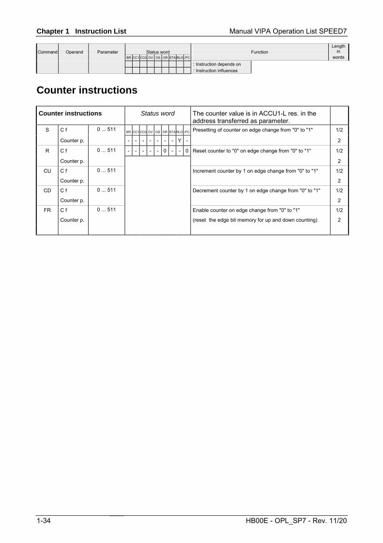
Chapter 1 Instruction List Manual VIPA Operation List SPEED7
Command
Operand
Parameter
Status word
Function
Length in
BR CC1 CC0 OV OS OR STA RLO /FC words : Instruction depends on : Instruction influences
1-34 HB00E - OPL_SP7 - Rev. 11/20
Counter instructions
Counter instructions Status word The counter value is in ACCU1-L res. in the address transferred as parameter.
S C f 0 ... 511 BR CC1 CC0 OV OS OR STA RLO /FC Presetting of counter on edge change from "0" to "1" 1/2
Counter p. - - - - - - - Y - 2
R C f 0 ... 511 - - - - - 0 - - 0 Reset counter to "0" on edge change from "0" to "1" 1/2
Counter p. 2
CU C f 0 ... 511 Increment counter by 1 on edge change from "0" to "1" 1/2
Counter p. 2
CD C f 0 ... 511 Decrement counter by 1 on edge change from "0" to "1" 1/2
Counter p. 2
FR C f 0 ... 511 Enable counter on edge change from "0" to "1" 1/2
Counter p. (reset the edge bit memory for up and down counting) 2
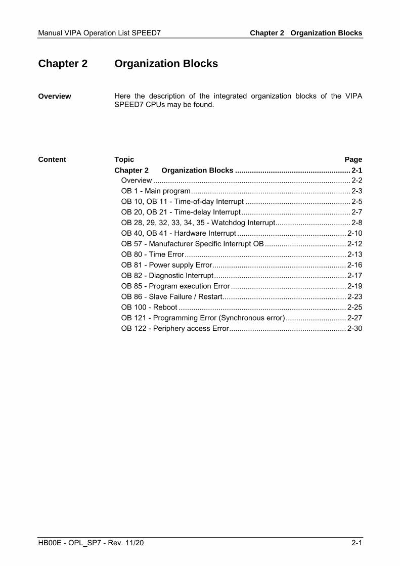
Manual VIPA Operation List SPEED7 Chapter 2 Organization Blocks
HB00E - OPL_SP7 - Rev. 11/20 2-1
Chapter 2 Organization Blocks
Here the description of the integrated organization blocks of the VIPA SPEED7 CPUs may be found.
Topic Page Chapter 2 Organization Blocks ....................................................... 2-1
Overview .............................................................................................. 2-2 OB 1 - Main program............................................................................ 2-3 OB 10, OB 11 - Time-of-day Interrupt .................................................. 2-5 OB 20, OB 21 - Time-delay Interrupt.................................................... 2-7 OB 28, 29, 32, 33, 34, 35 - Watchdog Interrupt.................................... 2-8 OB 40, OB 41 - Hardware Interrupt .................................................... 2-10 OB 57 - Manufacturer Specific Interrupt OB....................................... 2-12 OB 80 - Time Error............................................................................. 2-13 OB 81 - Power supply Error................................................................ 2-16 OB 82 - Diagnostic Interrupt............................................................... 2-17 OB 85 - Program execution Error ....................................................... 2-19 OB 86 - Slave Failure / Restart........................................................... 2-23 OB 100 - Reboot ................................................................................ 2-25 OB 121 - Programming Error (Synchronous error) ............................. 2-27 OB 122 - Periphery access Error........................................................ 2-30
Overview
Content
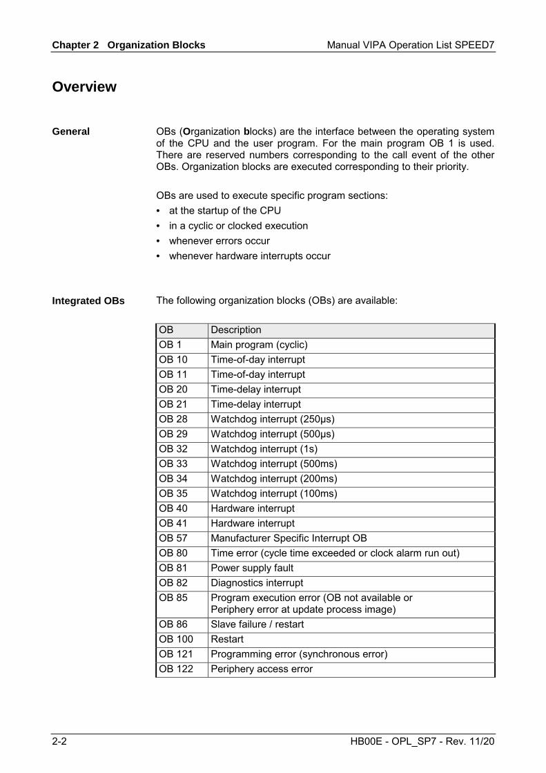
Chapter 2 Organization Blocks Manual VIPA Operation List SPEED7
2-2 HB00E - OPL_SP7 - Rev. 11/20
Overview
OBs (Organization blocks) are the interface between the operating system of the CPU and the user program. For the main program OB 1 is used. There are reserved numbers corresponding to the call event of the other OBs. Organization blocks are executed corresponding to their priority. OBs are used to execute specific program sections: • at the startup of the CPU • in a cyclic or clocked execution • whenever errors occur • whenever hardware interrupts occur
The following organization blocks (OBs) are available: OB Description OB 1 Main program (cyclic) OB 10 Time-of-day interrupt OB 11 Time-of-day interrupt OB 20 Time-delay interrupt OB 21 Time-delay interrupt OB 28 Watchdog interrupt (250µs) OB 29 Watchdog interrupt (500µs) OB 32 Watchdog interrupt (1s) OB 33 Watchdog interrupt (500ms) OB 34 Watchdog interrupt (200ms) OB 35 Watchdog interrupt (100ms) OB 40 Hardware interrupt OB 41 Hardware interrupt OB 57 Manufacturer Specific Interrupt OB OB 80 Time error (cycle time exceeded or clock alarm run out) OB 81 Power supply fault OB 82 Diagnostics interrupt OB 85 Program execution error (OB not available or
Periphery error at update process image) OB 86 Slave failure / restart OB 100 Restart OB 121 Programming error (synchronous error) OB 122 Periphery access error
General
Integrated OBs

Manual VIPA Operation List SPEED7 Chapter 2 Organization Blocks
HB00E - OPL_SP7 - Rev. 11/20 2-3
OB 1 - Main program
The operating system of the CPU executes OB 1 cyclically. After STARTUP to RUN the cyclical processing of the OB 1 is started. OB 1 has the lowest priority (priority 1) of each cycle time monitored OB. Within the OB 1 functions and function blocks can be called.
When OB 1 has been executed, the operating system sends global data. Before restarting OB 1, the operating system writes the process-image output table to the output modules, updates the process-image input table and receives any global data for the CPU. Cycle time is the time required for processing the OB 1. It also includes the scan time for higher priority classes which interrupt the main program respectively communication processes of the operating system. This comprises system control of the cyclic program scanning, process image update and refresh of the time functions. By means of the Siemens SIMATIC manager the recent cycle time of an online connected CPU may be shown. With PLC > Module Information > Scan cycle time the min., max. and recent cycle time can be displayed. The CPU offers a scan cycle watchdog for the max. cycle time. The default value for the max. cycle time is 150ms as scan cycle monitoring time. This value can be reconfigured or restarted by means of the SFC 43 (RE_TRIGR) at every position of your program. If the main program takes longer to scan than the specified scan cycle monitoring time, the OB 80 (Timeout) is called by the CPU. If OB 80 has not been programmed, the CPU goes to STOP. Besides the monitoring of the max. cycle time the observance of the min cycle time can be guaranteed. Here the restart of a new cycle (writing of process image of the outputs) is delayed by the CPU as long as the min. cycle time is reached.
The CPU's operating system forwards start information to OB 1, as it does to every OB, in the first 20 bytes of temporary local data. The start information can be accessed by means of the system function SFC 6 RD_SINFO. Note that direct reading of the start information for an OB is possible only in that OB because that information consists of temporary local data. More information can be found at chapter "Integrated standard SFCs".
Description
Function
Cycle time
Scan cycle monitoring time
Access to local data

Chapter 2 Organization Blocks Manual VIPA Operation List SPEED7
2-4 HB00E - OPL_SP7 - Rev. 11/20
The following table describes the start information of the OB 1 with default names of the variables and its data types:
Variable Type Description OB1_EV_CLASS BYTE Event class and identifiers:
11h: OB 1 active OB1_SCAN_1 BYTE 01h: completion of a restart
02h: completion of a hot restart 03h: completion of the main cycle 04h: completion of a cold restart 05h: first OB 1 cycle of the new master CPU after master-reserve switchover and STOP of the previous master
OB1_PRIORITY BYTE Priority class: 1 OB1_OB_NUMBR BYTE OB number (01) OB1_RESERVED_1 BYTE reserved OB1_RESERVED_2 BYTE reserved OB1_PREV_CYCLE INT Run time of previous cycle (ms) OB1_MIN_CYCLE INT Minimum cycle time (ms) since the last startup OB1_MAX_CYCLE INT Maximum cycle time (ms) since the last startup OB1_DATE_TIME DATE_AND_TIME Date and time of day when the OB was called
Local data

Manual VIPA Operation List SPEED7 Chapter 2 Organization Blocks
HB00E - OPL_SP7 - Rev. 11/20 2-5
OB 10, OB 11 - Time-of-day Interrupt
Time-of-day interrupts are used when you want to run a program at a particular time, either once only or periodically. Time-of-day interrupts can be configured within the hardware configuration or controlled by means of system functions in your main program at run time. The prerequisite for proper handling of time-of-day interrupts is a correctly set real-time clock on the CPU. For execution there are the following intervals: • once • every minute • hourly • daily • weekly • monthly • once at year • at the end of each month
Note! For monthly execution of a time-of-day interrupt OBs, only the day 1, 2, ...28 can be used as a starting date.
To start a time-of-day interrupt, you must first set and than activate the interrupt. The three following start possibilities exist: • The time-of-day interrupts are configured via the hardware
configuration. Open the selected CPU with Edit > Object properties > Time-of-Day interrupts. Here the corresponding time-of-day interrupts may be adjusted and activated. After transmission to CPU and startup the monitoring of time-of-day interrupt is automatically started.
• Set the time-of-day interrupt within the hardware configuration as shown above and then activate it by calling SFC 30 ACT_TINT in your program.
• You set the time-of-day interrupt by calling SFC 28 SET_TINT and then activate it by calling SFC 30 ACT_TINT.
The time-of-day interrupt can be delayed and enabled with the system functions SFC 41 DIS_AIRT and SFC 42 EN_AIRT. If a time-of-day interrupt OB is called but was not programmed, the operating system calls OB 85. If OB 85 was not programmed, the CPU goes to STOP. Is there an error at time-of-day interrupt processing e.g. start time has already passed, the time error OB 80 is called. The time-of-day interrupt OB is then executed precisely once.
Description
Function
Behavior on error

Chapter 2 Organization Blocks Manual VIPA Operation List SPEED7
2-6 HB00E - OPL_SP7 - Rev. 11/20
The possibilities of activation of time-of-day interrupts is shown at the following table: Interval Description Not activated The time-of-day interrupt is not executed, even when
loaded in the CPU. It may be activated by calling SFC 30.
Activated once only
The time-of-day OB is cancelled automatically after it runs the one time specified. Your program can use SFC 28 and SFC 30 to reset and reactivate the OB.
Activated periodically
When the time-of-day interrupt occurs, the CPU calculates the next start time for the time-of-day interrupt based on the current time of day and the period.
The following table describes the start information of the OB 10 and 11 with default names of the variables and its data types:
Variable Type Description OB10_EV_CLASS BYTE Event class and identifiers:
11h: interrupt is active OB10_STRT_INFO BYTE 11h: Start request for OB 10
12h: Start request for OB 11 OB10_PRIORITY BYTE Assigned priority class: default 2 OB10_OB_NUMBR BYTE OB number (10, 11) OB10_RESERVED_1 BYTE reserved OB10_RESERVED_2 BYTE reserved OB10_PERIOD_EXE WORD The OB is executed at the specified intervals:
0000h: once 0201h: once every minute 0401h: once hourly 1001h: once daily 1201h: once weekly 1401h: once monthly 1801h: once yearly 2001h: end of month
OB10_RESERVED_3 INT reserved OB10_RESERVED_4 INT reserved OB10_DATE_TIME DATE_AND_TIME Date and time of day when the OB was called
Information to access the local data can be found at the description of the OB 1.
Possibilities of activation
Local data for time-of-day interrupt OB
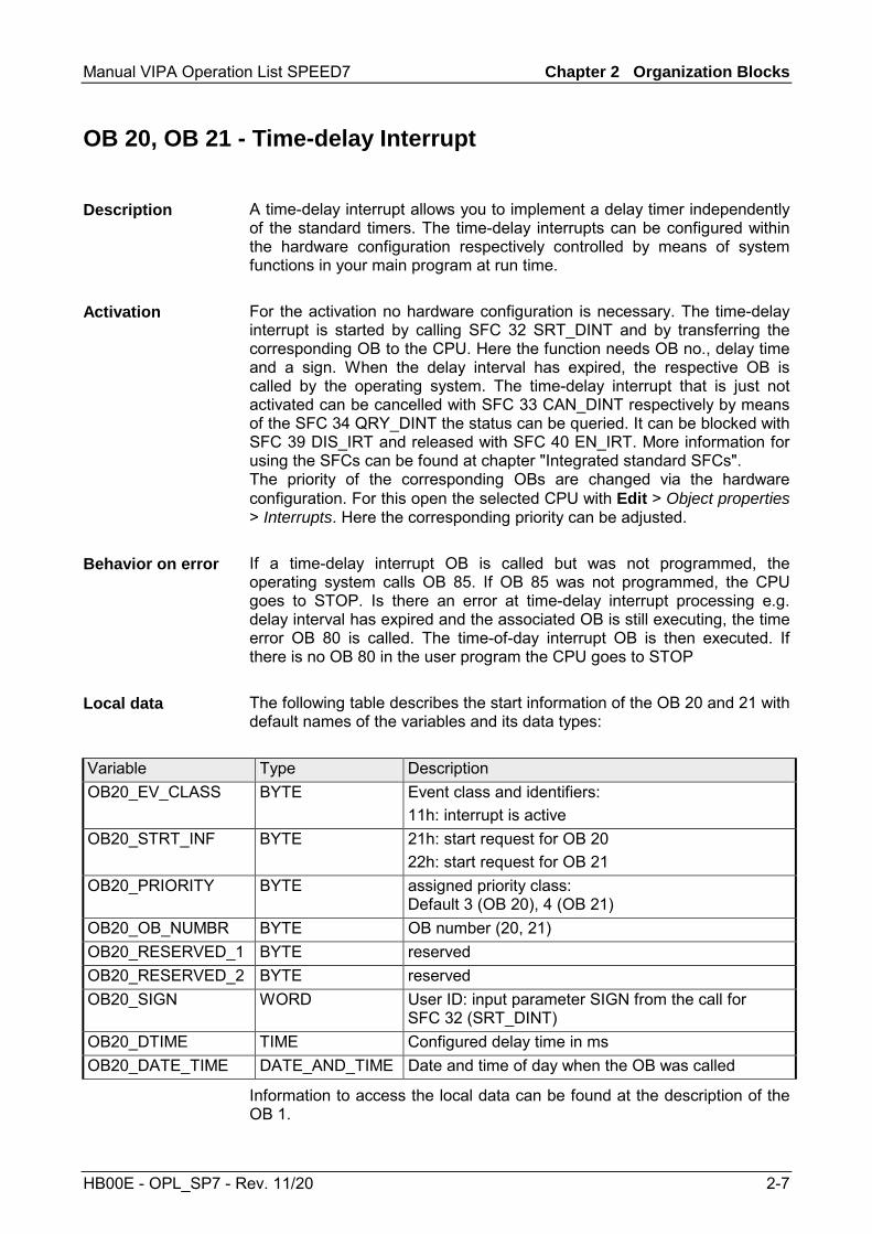
Manual VIPA Operation List SPEED7 Chapter 2 Organization Blocks
HB00E - OPL_SP7 - Rev. 11/20 2-7
OB 20, OB 21 - Time-delay Interrupt
A time-delay interrupt allows you to implement a delay timer independently of the standard timers. The time-delay interrupts can be configured within the hardware configuration respectively controlled by means of system functions in your main program at run time. For the activation no hardware configuration is necessary. The time-delay interrupt is started by calling SFC 32 SRT_DINT and by transferring the corresponding OB to the CPU. Here the function needs OB no., delay time and a sign. When the delay interval has expired, the respective OB is called by the operating system. The time-delay interrupt that is just not activated can be cancelled with SFC 33 CAN_DINT respectively by means of the SFC 34 QRY_DINT the status can be queried. It can be blocked with SFC 39 DIS_IRT and released with SFC 40 EN_IRT. More information for using the SFCs can be found at chapter "Integrated standard SFCs". The priority of the corresponding OBs are changed via the hardware configuration. For this open the selected CPU with Edit > Object properties > Interrupts. Here the corresponding priority can be adjusted. If a time-delay interrupt OB is called but was not programmed, the operating system calls OB 85. If OB 85 was not programmed, the CPU goes to STOP. Is there an error at time-delay interrupt processing e.g. delay interval has expired and the associated OB is still executing, the time error OB 80 is called. The time-of-day interrupt OB is then executed. If there is no OB 80 in the user program the CPU goes to STOP The following table describes the start information of the OB 20 and 21 with default names of the variables and its data types:
Variable Type Description OB20_EV_CLASS BYTE Event class and identifiers:
11h: interrupt is active OB20_STRT_INF BYTE 21h: start request for OB 20
22h: start request for OB 21 OB20_PRIORITY BYTE assigned priority class:
Default 3 (OB 20), 4 (OB 21) OB20_OB_NUMBR BYTE OB number (20, 21) OB20_RESERVED_1 BYTE reserved OB20_RESERVED_2 BYTE reserved OB20_SIGN WORD User ID: input parameter SIGN from the call for
SFC 32 (SRT_DINT) OB20_DTIME TIME Configured delay time in ms OB20_DATE_TIME DATE_AND_TIME Date and time of day when the OB was called
Information to access the local data can be found at the description of the OB 1.
Description
Activation
Behavior on error
Local data

Chapter 2 Organization Blocks Manual VIPA Operation List SPEED7
2-8 HB00E - OPL_SP7 - Rev. 11/20
OB 28, 29, 32, 33, 34, 35 - Watchdog Interrupt
By means of a watchdog interrupt the cyclical processing can be interrupted in equidistant time intervals The start time of the time interval and the phase offset is the instant of transition from STARTUP to RUN after execution of OB 100.
Watchdog interrupt OB Default time interval Default priority class Option for phase offsetOB 28 250µs 24 no* OB 29 500µs 24 no* OB 32 1s 09 yes OB 33 500ms 10 yes OB 34 200ms 11 yes OB 35 100ms 12 yes
*) If both OBs are activated OB 28 is executed first and then OB 29. Due to the very short time intervals and the high priority a simultaneous execution of OB 28 and OB 29 should be avoided.
A watchdog interrupt is activated by programming the corresponding OB within the CPU. The watchdog interrupt can be delayed and enabled with the system functions SFC 41 DIS_AIRT and SFC 42 EN_AIRT.
After startup to RUN the activated watchdog OBs are called in the configured equidistant intervals with consideration of the phase shift. The equidistant start times of the Watchdog OBs result of the respective time frame and the phase shift. So a sub program can be called time controlled by programming a respective OB. The phase offset can be used to stagger the execution of watchdog interrupt handling routines despite the fact that these routines are timed to a multiple of the same interval. The use of the phase offset achieves a higher interval accuracy. The start time of the time interval and the phase offset is the instant of transition from STARTUP to RUN. The call instant for a watchdog interrupt OB is thus the time interval plus the phase offset.
Time interval, phase offset (not OB 28, 29) and priority may be parameterized by the hardware configurator. Depending on the OB there are the following possibilities for parameterization: OB 28, 29, 33, 34: Parameterizable as VIPA specific parameter by the
properties of the SPEED7 CPU. OB 32, 35: Parameterizable by Siemens CPU 318-2DP.
Description
Activation
Function
Phase offset
Parameterization

Manual VIPA Operation List SPEED7 Chapter 2 Organization Blocks
HB00E - OPL_SP7 - Rev. 11/20 2-9
Note! You must make sure that the run time of each cyclic interrupt OB is significantly shorter than its interval. Otherwise the time error OB 80 is started. The watchdog interrupt that caused the error is executed later.
The following table describes the start information of the OB 28, 29, 32 and 35 with default names of the variables and its data types:
Variable Type Description OB35_EV_CLASS BYTE Event class and identifiers:
11h: Cyclic interrupt is active OB35_STRT_INF BYTE 2Fh: Start request for OB 28
30h: Start request for OB 29 33h: Start request for OB 32 36h: Start request for OB 35
OB35_PRIORITY BYTE Assigned priority class; Defaults: 24 (OB 28, 29); 9 (OB 32), 12 (OB 35)
OB35_OB_NUMBR BYTE OB number (28, 29, 32, 35) OB35_RESERVED_1 BYTE reserved OB35_RESERVED_2 BYTE reserved OB35_PHASE_OFFSET WORD Phase offset in ms OB35_RESERVED_3 INT reserved OB35_EXT_FREQ INT Interval in ms OB35_DATE_TIME DATE_AND_TIME Date and time of day when the OB was called
Information to access the local data can be found at the description of the OB 1.
Note! Since the blocks SFC58/59 respectively SFB52/53 for reading and writing data blocks cannot be interrupted, in conjunction with OB 28 and OB 29 the CPU may change to STOP state!
Local data

Chapter 2 Organization Blocks Manual VIPA Operation List SPEED7
2-10 HB00E - OPL_SP7 - Rev. 11/20
OB 40, OB 41 - Hardware Interrupt
Hardware interrupts are used to enable the immediate detection in the user program of events in the controlled process, making it possible to respond with an appropriate interrupt handling routine. Here OB 40 and OB 41 can be used. Within the configuration you specify for each module, which channels release a hardware interrupt during which conditions. With the system functions SFC 55 WR_PARM, SFC 56 WR_DPARM and SFC 57 PARM_MOD you can (re)parameterize the modules with hardware interrupt capability even in RUN.
The hardware interrupt processing of the CPU is always active. So that a module can release a hardware interrupt, you have to activate the hard-ware interrupt on the appropriate module by a hardware configuration. Here you can specify whether the hardware interrupt should be generated for a coming event, a leaving event or both.
After a hardware interrupt has been triggered by the module, the operating system identifies the slot and the corresponding hardware interrupt OB. If this OB has a higher priority than the currently active priority class, it will be started. The channel-specific acknowledgement is sent after this hardware interrupt OB has been executed. If another event that triggers a hardware interrupt occurs on the same module during the time between identification and acknowledgement of a hardware interrupt, the following applies: • If the event occurs on the channel that previously triggered the hardware
interrupt, then the new interrupt is lost. • If the event occurs on another channel of the same module, then no
hardware interrupt can currently be triggered. This interrupt, however, is not lost, but is triggered if just active after the acknowledgement of the currently active hardware interrupt. Else it is lost.
• If a hardware interrupt is triggered and its OB is currently active due to a hardware interrupt from another module, the new request can be processed only if it is still active after acknowledgement.
During STARTUP there is no hardware interrupt produced. The treatment of interrupts starts with the transition to operating mode RUN. Hardware interrupts during transition to RUN are lost.
If a hardware interrupt is generated for which there is no hardware interrupt OB in the user program, OB 85 is called by the operating system. The hardware interrupt is acknowledged. If OB 85 has not been programmed, the CPU goes to STOP.
Description
Activation
Function
Behavior on error
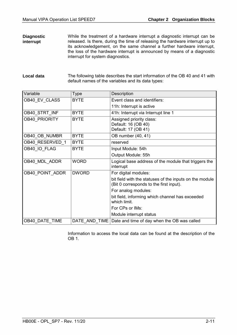
Manual VIPA Operation List SPEED7 Chapter 2 Organization Blocks
HB00E - OPL_SP7 - Rev. 11/20 2-11
While the treatment of a hardware interrupt a diagnostic interrupt can be released. Is there, during the time of releasing the hardware interrupt up to its acknowledgement, on the same channel a further hardware interrupt, the loss of the hardware interrupt is announced by means of a diagnostic interrupt for system diagnostics.
The following table describes the start information of the OB 40 and 41 with default names of the variables and its data types:
Variable Type Description OB40_EV_CLASS BYTE Event class and identifiers:
11h: Interrupt is active OB40_STRT_INF BYTE 41h: Interrupt via Interrupt line 1 OB40_PRIORITY BYTE Assigned priority class:
Default: 16 (OB 40) Default: 17 (OB 41)
OB40_OB_NUMBR BYTE OB number (40, 41) OB40_RESERVED_1 BYTE reserved OB40_IO_FLAG BYTE Input Module: 54h
Output Module: 55h OB40_MDL_ADDR WORD Logical base address of the module that triggers the
interrupt OB40_POINT_ADDR DWORD For digital modules:
bit field with the statuses of the inputs on the module (Bit 0 corresponds to the first input). For analog modules: bit field, informing which channel has exceeded which limit. For CPs or IMs: Module interrupt status
OB40_DATE_TIME DATE_AND_TIME Date and time of day when the OB was called Information to access the local data can be found at the description of the OB 1.
Diagnostic interrupt
Local data
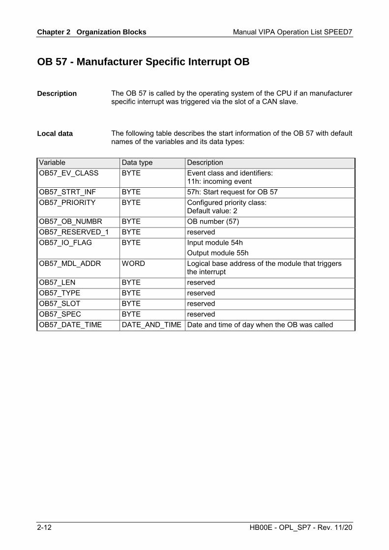
Chapter 2 Organization Blocks Manual VIPA Operation List SPEED7
2-12 HB00E - OPL_SP7 - Rev. 11/20
OB 57 - Manufacturer Specific Interrupt OB
The OB 57 is called by the operating system of the CPU if an manufacturer specific interrupt was triggered via the slot of a CAN slave.
The following table describes the start information of the OB 57 with default names of the variables and its data types:
Variable Data type Description OB57_EV_CLASS BYTE Event class and identifiers:
11h: incoming event OB57_STRT_INF BYTE 57h: Start request for OB 57 OB57_PRIORITY BYTE Configured priority class:
Default value: 2 OB57_OB_NUMBR BYTE OB number (57) OB57_RESERVED_1 BYTE reserved OB57_IO_FLAG BYTE Input module 54h
Output module 55h OB57_MDL_ADDR WORD Logical base address of the module that triggers
the interrupt OB57_LEN BYTE reserved OB57_TYPE BYTE reserved OB57_SLOT BYTE reserved OB57_SPEC BYTE reserved OB57_DATE_TIME DATE_AND_TIME Date and time of day when the OB was called
Description
Local data

Manual VIPA Operation List SPEED7 Chapter 2 Organization Blocks
HB00E - OPL_SP7 - Rev. 11/20 2-13
OB 80 - Time Error
The operating system of the CPU calls OB 80 whenever an error occurs like: • Cycle monitoring time exceeded • OB request error i.e. the requested OB is still executed or an OB was
requested too frequently within a given priority class. • Time-of-day interrupt error i.e. interrupt time past because clock was set
forward or after transition to RUN. The time error OB can be blocked, respectively delayed and released by means of SFC 39 ... 42.
Note! If OB 80 has not been programmed, the CPU changes to the STOP mode. If OB 80 is called twice during the same scan cycle due to the scan time being exceeded, the CPU changes to the STOP mode. You can prevent this by calling SFC 43 RE_TRIGR at a suitable point in the program.
The following table describes the start information of the OB 80 with default names of the variables and its data types:
Variable Type Description OB80_EV_CLASS BYTE Event class and identifiers: 35h OB80_FLT_ID BYTE Error code (possible values:
01h, 02h, 05h, 06h, 07h, 08h, 09h, 0Ah) OB80_PRIORITY BYTE Priority class: 26 (RUN mode)
28 (Overflow of the OB request buffer) OB80_OB_NUMBR BYTE OB number (80) OB80_RESERVED_1 BYTE reserved OB80_RESERVED_2 BYTE reserved OB80_ERROR_INFO WORD Error information: depending on error code OB80_ERR_EV_CLASS BYTE Event class for the start event that caused the errorOB80_ERR_EV_NUM BYTE Event number for the start event that caused the
error OB80_OB_PRIORITY BYTE Error information: depending on error code OB80_OB_NUM BYTE Error information: depending on error code OB80_DATE_TIME DATE_AND_TIME Date and time of day when the OB was called
Information to access the local data can be found at the description of the OB 1.
Description
Local data

Chapter 2 Organization Blocks Manual VIPA Operation List SPEED7
2-14 HB00E - OPL_SP7 - Rev. 11/20
The variables dependent on the error code have the following allocation:
Error code Variable Bit Description 01h Cycle time exceeded OB80_ERROR_INFO Run time of last scan cycle (ms) OB80_ERR_EV_CLASS Class of the event that triggered the
interrupt OB80_ERR_EV_NUM Number of the event that triggered the
interrupt OB80_OB_PRIORITY Priority class of the OB which was being
executed when the error occurred OB80_OB_NUM Number of the OB which was being
executed when the error occurred 02h The called OB is still being executed OB80_ERROR_INFO The respective temporary variable of the
called block which is determined by OB80_ERR_EV_CLASS and OB80_ERR_EV_NUM
OB80_ERR_EV_CLASS Class of the event that triggered the interrupt
OB80_ERR_EV_NUM Number of the event that triggered the interrupt
OB80_OB_PRIORITY Priority class of the OB causing the error OB80_OB_NUM Number of the OB causing the error 05h and 06h
Elapsed time-of-day interrupt due to moving the clock forward
Elapsed time-of-day interrupt on return to RUN after HOLD
OB80_ERROR_INFO Bit 0 = "1" The start time for time-of-day interrupt 0 is in the past
... ... Bit 7 = "1" The start time for time-of-day interrupt 7 is
in the past
OB80_ERR_EV_CLASS Bit 15 ... 8 Not used
Not used OB80_ERR_EV_NUM Not used OB80_OB_PRIORITY Not used OB80_OB_NUM Not used
continued ...
Variables depending on error code
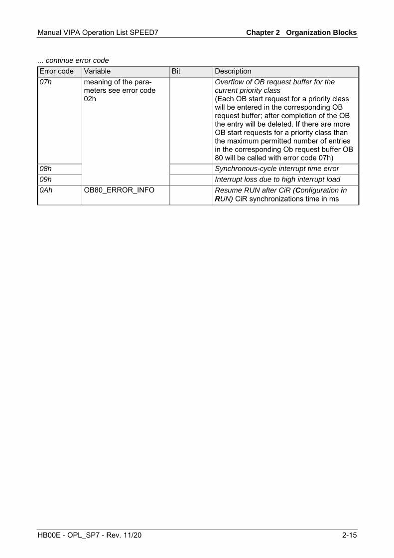
Manual VIPA Operation List SPEED7 Chapter 2 Organization Blocks
HB00E - OPL_SP7 - Rev. 11/20 2-15
... continue error code Error code Variable Bit Description 07h Overflow of OB request buffer for the
current priority class (Each OB start request for a priority class will be entered in the corresponding OB request buffer; after completion of the OB the entry will be deleted. If there are more OB start requests for a priority class than the maximum permitted number of entries in the corresponding Ob request buffer OB 80 will be called with error code 07h)
08h Synchronous-cycle interrupt time error 09h
meaning of the para-meters see error code 02h
Interrupt loss due to high interrupt load 0Ah OB80_ERROR_INFO Resume RUN after CiR (Configuration in
RUN) CiR synchronizations time in ms

Chapter 2 Organization Blocks Manual VIPA Operation List SPEED7
2-16 HB00E - OPL_SP7 - Rev. 11/20
OB 81 - Power supply Error
The operating system of the CPU calls OB 81 whenever an event occurs that is triggered by an error or fault related to the power supply (when entering and when outgoing event). The CPU does not change to the STOP mode if OB 81 is not programmed. You can disable or delay and re-enable the power supply error OB using SFCs 39 ... 42.
The following table describes the start information of the OB 81 with default names of the variables and its data types:
Variable Data type Description OB81_EV_CLASS BYTE Event class and identifiers:
39h: incoming event OB81_FLT_ID BYTE Error code:
22h: Back-up voltage missing OB81_PRIORITY BYTE Priority class:
28 (mode STARTUP) OB81_OB_NUMBR BYTE OB-NR. (81) OB81_RESERVED_1 BYTE reserved OB81_RESERVED_2 BYTE reserved OB81_RACK_CPU WORD Bit 2 ... 0: 000 (Rack number)
Bit 3: 1 (master CPU) Bit 7 ... 4: 1111 (fix)
OB81_RESERVED_3 BYTE reserved OB81_RESERVED_4 BYTE reserved OB81_RESERVED_5 BYTE reserved OB81_RESERVED_6 BYTE reserved OB80_DATE_TIME DATE_AND_TIME Date and time of day when the OB was called
Information to access the local data can be found at the description of the OB 1.
Description
Local Data

Manual VIPA Operation List SPEED7 Chapter 2 Organization Blocks
HB00E - OPL_SP7 - Rev. 11/20 2-17
OB 82 - Diagnostic Interrupt
The system diagnostic is the detection, evaluation and reporting of messages which occur within a PLC system. Examples of errors for these messages could be errors in the user program, module failures or wire breaks on signaling modules. If a module with diagnostic capability for which you have enabled the diagnostic interrupt detects an error, it outputs a request for a diagnostic interrupt to the CPU (when entering and outgoing event). The operating system then calls OB82. The local variables of OB82 contain the logical base address as well as four bytes of diagnostic data of the defective module. If OB82 has not been programmed, the CPU changes to the STOP mode. You can delay and re-enable the diagnostic interrupt OB using SFC 41 DIS_AIRT and SFC 42 EN_AIRT.
All diagnostic events reported to the CPU operating system are entered in the diagnostic buffer in the order in which they occurred, and with date and time stamp. This is a buffered memory area on the CPU that retains its contents even in the event of a memory reset. The diagnostic buffer is a ring buffer with. VIPA CPUs offer space for 100 entries. When the diagnostic buffer is full, the oldest entry is overwritten by the newest. By use of the PLC functions of the Siemens SIMATIC manager the diagnostic buffer can be queried. Besides of the standard entries in the diagnostic buffer, the VIPA CPUs support some additional specific entries in form of event-IDs. More information may be found at the manual of the CPU at the chapter "Deployment of the CPU ..." at "VIPA specific diagnostic entries".
Programmable diagnostic events are reported only when you have set the parameters necessary to enable diagnostics. Non-programmable diag-nostics events are always reported, regardless of whether or not diag-nostics have been enabled.
A diagnostic entry can be written to the diagnostic buffer by means of the system function SFC 52 WR_USMSG. More information can be found at chapter "Integrated standard SFCs".
You can use system function SFC 59 RD_REC (read record set) in OB 82 to obtain detailed error information. The diagnostic information are consistent until OB 82 is exited, that is, they remain "frozen". Exiting of OB 82 acknowledges the diagnostic interrupt on the module. The module's diagnostic data is in record sets DS 0 and DS 1. The record set DS 0 contains 4 byte of diagnostic data describing the current status of the module. The contents of these 4 byte are identical to the contents of byte 8 ... 11 of the OB 82 start information Record set DS 1 contains the 4 byte from record set DS 0 and, in addition, the module specific diagnostic data. More information about module specific diagnostic data can be found at the description of the appropriate module.
Description
Diagnostic in ring buffer
Configurable Diagnostics
Write diagnostics user entry with SFC
Read diagnostic data with SFC 59

Chapter 2 Organization Blocks Manual VIPA Operation List SPEED7
2-18 HB00E - OPL_SP7 - Rev. 11/20
The following table describes the start information of the OB 82 with default names of the variables and its data types:
Variable Data type Description OB82_EV_CLASS BYTE Event class and identifiers:
38h: outgoing event 39h: incoming event
OB82_FLT_ID BYTE Error code (42h) OB82_PRIORITY BYTE Priority class: can be assigned via hardware
configuration OB82_OB_NUMBR BYTE OB number (82) OB82_RESERVED_1 BYTE reserved OB82_IO_FLAG BYTE Input Module 54h
Output Module 55h OB82_MDL_ADDR INT Logical base address of the module where the
fault occurred OB82_MDL_DEFECT BOOL Module is defective OB82_INT_FAULT BOOL Internal fault OB82_EXT_FAULT BOOL External fault OB82_PNT_INFO BOOL Channel fault OB82_EXT_VOLTAGE BOOL External voltage failed OB82_FLD_CONNCTR BOOL Front panel connector not plugged in OB82_NO_CONFIG BOOL Module is not configured OB82_CONFIG_ERR BOOL Incorrect parameters on module OB82_MDL_TYPE BYTE Bit 3 ... 0: Module class
Bit 4: Channel information exists Bit 5: User information exists Bit 6: Diagnostic interrupt from substitute Bit 7: Reserved
OB82_SUB_MDL_ERR BOOL Submodule is missing or has an error OB82_COMM_FAULT BOOL Communication failure OB82_MDL_STOP BOOL Operating mode (0: RUN, 1:STOP) OB82_WTCH_DOG_FLT BOOL Watchdog timer responded OB82_INT_PS_FLT BOOL Internal power supply failed OB82_PRIM_BATT_FLT BOOL Battery exhausted OB82_BCKUP_BATT_FLT BOOL Entire backup failed OB82_RESERVED_2 BOOL Reserved OB82_RACK_FLT BOOL Expansion rack failure OB82_PROC_FLT BOOL Processor failure OB82_EPROM_FLT BOOL EPROM fault OB82_RAM_FLT BOOL RAM fault OB82_ADU_FLT BOOL ADC/DAC error OB82_FUSE_FLT BOOL Fuse tripped OB82_HW_INTR_FLT BOOL Hardware interrupt lost OB82_RESERVED_3 BOOL Reserved OB82_DATE_TIME DATE_AND_TIME Date and time of day when the OB was called
Information to access the local data can be found at the description of the OB 1.
Local data

Manual VIPA Operation List SPEED7 Chapter 2 Organization Blocks
HB00E - OPL_SP7 - Rev. 11/20 2-19
OB 85 - Program execution Error
The operating system of the CPU calls OB 85 whenever one of the following events occurs: • Start event for an OB that has not been loaded • Error when the operating system accesses a block • I/O access error during update of the process image by the system
(if the OB 85 call was not suppressed due to the configuration) The OB 85 may be delayed by means of the SFC 41 and re-enabled by the SFC 42.
Note! If OB 85 has not been programmed, the CPU changes to STOP mode when one of these events is detected.
The following table describes the start information of the OB 85 with default names of the variables and its data types:
Variable Type Description OB85_EV_CLASS BYTE Event class and identifiers: 35h
38h (only with error code B3h, B4h) 39h (only with error code B1h, B2h, B3h, B4h)
OB85_FLT_ID BYTE Error code (possible values: A1h, A2h, A3h, A4h, B1h, B2h, B3h, B4h)
OB85_PRIORITY BYTE Priority class: 26 (Default value mode RUN) 28 (mode ANLAUF)
OB85_OB_NUMBR BYTE OB number (85) OB85_RESERVED_1 BYTE reserved OB85_RESERVED_2 BYTE reserved OB85_RESERVED_3 INT reserved OB85_ERR_EV_CLASS BYTE Class of the event that caused the error OB85_ERR_EV_NUM BYTE Number of the event that caused the error OB85_OB_PRIOR BYTE Priority class of the OB that was active when the
error occurred OB85_OB_NUM BYTE Number of the OB that was active when the error
occurred OB85_DATE_TIME DATE_AND_TIME Date and time of day when the OB was called
Information to access the local data can be found at the description of the OB 1.
Description
Local data
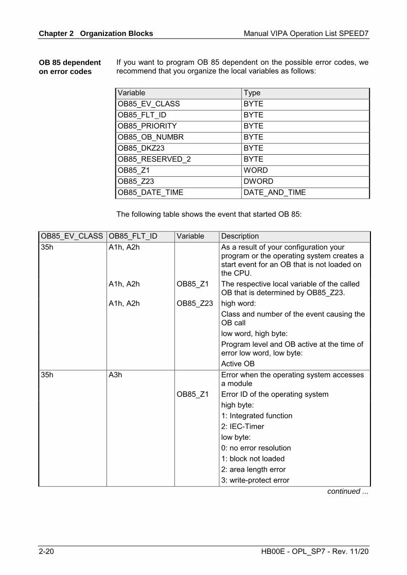
Chapter 2 Organization Blocks Manual VIPA Operation List SPEED7
2-20 HB00E - OPL_SP7 - Rev. 11/20
If you want to program OB 85 dependent on the possible error codes, we recommend that you organize the local variables as follows: Variable Type OB85_EV_CLASS BYTE OB85_FLT_ID BYTE OB85_PRIORITY BYTE OB85_OB_NUMBR BYTE OB85_DKZ23 BYTE OB85_RESERVED_2 BYTE OB85_Z1 WORD OB85_Z23 DWORD OB85_DATE_TIME DATE_AND_TIME The following table shows the event that started OB 85:
OB85_EV_CLASS OB85_FLT_ID Variable Description 35h A1h, A2h
As a result of your configuration your
program or the operating system creates a start event for an OB that is not loaded on the CPU.
A1h, A2h OB85_Z1 The respective local variable of the called OB that is determined by OB85_Z23.
A1h, A2h OB85_Z23 high word: Class and number of the event causing the OB call
low word, high byte: Program level and OB active at the time of error low word, low byte: Active OB
35h A3h Error when the operating system accesses a module
OB85_Z1 Error ID of the operating system high byte:
1: Integrated function 2: IEC-Timer
low byte: 0: no error resolution 1: block not loaded 2: area length error 3: write-protect error
continued ...
OB 85 dependent on error codes
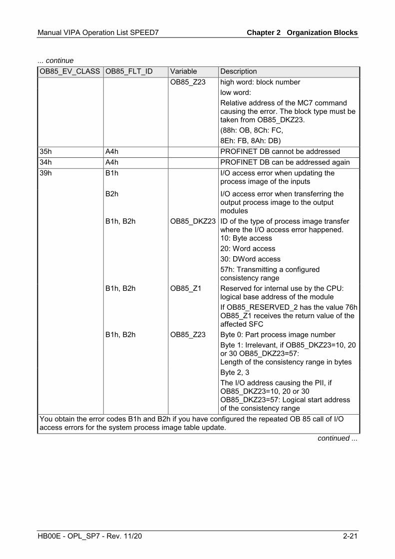
Manual VIPA Operation List SPEED7 Chapter 2 Organization Blocks
HB00E - OPL_SP7 - Rev. 11/20 2-21
... continue OB85_EV_CLASS OB85_FLT_ID Variable Description OB85_Z23 high word: block number low word:
Relative address of the MC7 command causing the error. The block type must be taken from OB85_DKZ23. (88h: OB, 8Ch: FC, 8Eh: FB, 8Ah: DB)
35h A4h PROFINET DB cannot be addressed 34h A4h PROFINET DB can be addressed again 39h B1h
I/O access error when updating the
process image of the inputs
B2h I/O access error when transferring the output process image to the output modules
B1h, B2h
OB85_DKZ23 ID of the type of process image transfer where the I/O access error happened. 10: Byte access 20: Word access 30: DWord access 57h: Transmitting a configured consistency range
B1h, B2h OB85_Z1 Reserved for internal use by the CPU: logical base address of the module If OB85_RESERVED_2 has the value 76h OB85_Z1 receives the return value of the affected SFC
B1h, B2h OB85_Z23 Byte 0: Part process image number Byte 1: Irrelevant, if OB85_DKZ23=10, 20
or 30 OB85_DKZ23=57: Length of the consistency range in bytes
Byte 2, 3 The I/O address causing the PII, if OB85_DKZ23=10, 20 or 30 OB85_DKZ23=57: Logical start address of the consistency range
You obtain the error codes B1h and B2h if you have configured the repeated OB 85 call of I/O access errors for the system process image table update.
continued ...
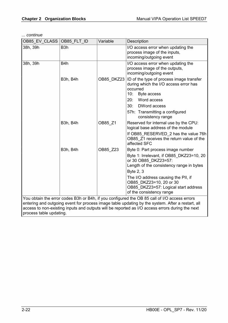
Chapter 2 Organization Blocks Manual VIPA Operation List SPEED7
2-22 HB00E - OPL_SP7 - Rev. 11/20
... continue OB85_EV_CLASS OB85_FLT_ID Variable Description 38h, 39h B3h
I/O access error when updating the
process image of the inputs, incoming/outgoing event
38h, 39h B4h I/O access error when updating the process image of the outputs, incoming/outgoing event
B3h, B4h
OB85_DKZ23 ID of the type of process image transfer during which the I/O access error has occurred 10: Byte access 20: Word access 30: DWord access 57h: Transmitting a configured consistency range
B3h, B4h OB85_Z1 Reserved for internal use by the CPU: logical base address of the module If OB85_RESERVED_2 has the value 76h OB85_Z1 receives the return value of the affected SFC
B3h, B4h OB85_Z23 Byte 0: Part process image number Byte 1: Irrelevant, if OB85_DKZ23=10, 20
or 30 OB85_DKZ23=57: Length of the consistency range in bytes
Byte 2, 3 The I/O address causing the PII, if OB85_DKZ23=10, 20 or 30 OB85_DKZ23=57: Logical start address of the consistency range
You obtain the error codes B3h or B4h, if you configured the OB 85 call of I/O access errors entering and outgoing event for process image table updating by the system. After a restart, all access to non-existing inputs and outputs will be reported as I/O access errors during the next process table updating.

Manual VIPA Operation List SPEED7 Chapter 2 Organization Blocks
HB00E - OPL_SP7 - Rev. 11/20 2-23
OB 86 - Slave Failure / Restart
The operating system of the CPU calls OB 86 whenever the failure of a slave is detected (both when entering and outgoing event).
Note! If OB 86 has not been programmed, the CPU changes to the STOP mode when this type of error is detected.
The OB 86 may be delayed by means of the SFC 41 and re-enabled by the SFC 42.
The following table describes the start information of the OB 86 with default names of the variables and its data types:
Variable Type Description OB86_EV_CLASS BYTE Event class and identifiers:
38h: outgoing event 39h: incoming event
OB86_FLT_ID BYTE Error code: (possible values: C4h, C5h, C7h, C8h)
OB86_PRIORITY BYTE Priority class: may be assigned via hardware configuration
OB86_OB_NUMBR BYTE OB number (86) OB86_RESERVED_1 BYTE reserved OB86_RESERVED_2 BYTE reserved OB86_MDL_ADDR WORD Depends on the error code OB86_RACKS_FLTD ARRAY (0 ... 31)
OF BOOL Depends on the error code
OB86_DATE_TIME DATE_AND_TIME Date and time of day when the OB was called Information to access the local data can be found at the description of the OB 1.
Description
Local data
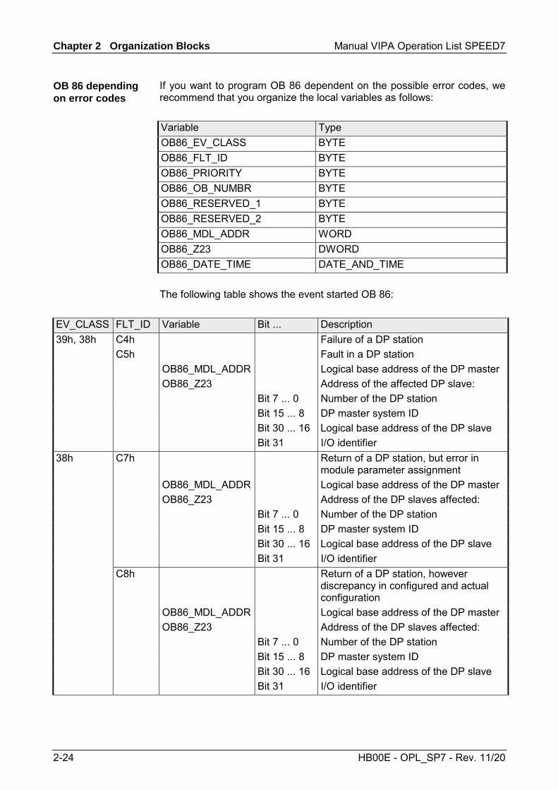
Chapter 2 Organization Blocks Manual VIPA Operation List SPEED7
2-24 HB00E - OPL_SP7 - Rev. 11/20
If you want to program OB 86 dependent on the possible error codes, we recommend that you organize the local variables as follows: Variable Type OB86_EV_CLASS BYTE OB86_FLT_ID BYTE OB86_PRIORITY BYTE OB86_OB_NUMBR BYTE OB86_RESERVED_1 BYTE OB86_RESERVED_2 BYTE OB86_MDL_ADDR WORD OB86_Z23 DWORD OB86_DATE_TIME DATE_AND_TIME The following table shows the event started OB 86:
EV_CLASS FLT_ID Variable Bit ... Description 39h, 38h C4h Failure of a DP station C5h Fault in a DP station OB86_MDL_ADDR Logical base address of the DP master OB86_Z23 Address of the affected DP slave: Bit 7 ... 0 Number of the DP station Bit 15 ... 8 DP master system ID Bit 30 ... 16 Logical base address of the DP slave Bit 31 I/O identifier 38h C7h Return of a DP station, but error in
module parameter assignment OB86_MDL_ADDR Logical base address of the DP master OB86_Z23 Address of the DP slaves affected: Bit 7 ... 0 Number of the DP station Bit 15 ... 8 DP master system ID Bit 30 ... 16 Logical base address of the DP slave Bit 31 I/O identifier C8h Return of a DP station, however
discrepancy in configured and actual configuration
OB86_MDL_ADDR Logical base address of the DP master OB86_Z23 Address of the DP slaves affected: Bit 7 ... 0 Number of the DP station Bit 15 ... 8 DP master system ID Bit 30 ... 16 Logical base address of the DP slave Bit 31 I/O identifier
OB 86 depending on error codes

Manual VIPA Operation List SPEED7 Chapter 2 Organization Blocks
HB00E - OPL_SP7 - Rev. 11/20 2-25
OB 100 - Reboot
On a restart, the CPU sets both itself and the modules to the programmed initial state, deletes all not-latching data in the system memory, calls OB 100 and then executes the main program in OB 1. Here the current program and the current data blocks generated by SFC remain in memory. The VIPA CPU executes a startup with OB 100 as follows: • after POWER ON and operating switch in RUN • whenever you switch the mode selector from STOP to RUN • after a request using a communication function (menu command from
the programming device) Even if no OB 100 is loaded into the CPU, the CPU goes to RUN without an error message.
The following table describes the start information of the OB 100 with default names of the variables and its data types:
Variable Type Description OB100_EV_CLASS BYTE Event class and identifiers: 13h: active OB100_STRTUP BYTE Startup request
81h: Manuel restart 82h: Automatic restart
OB100_PRIORITY BYTE Priority class: 27 OB100_OB_NUMBR BYTE OB number (100) OB100_RESERVED_1 BYTE reserved OB100_RESERVED_2 BYTE reserved OB100_STOP WORD Number of the event that caused the CPU to STOPOB100_STRT_INFO DWORD Supplementary information about the current
startup (see next page) OB100_DATE_TIME DATE_AND_TIME Date and time of day when the OB was called
Information to access the local data can be found at the description of the OB 1.
Description
Local data

Chapter 2 Organization Blocks Manual VIPA Operation List SPEED7
2-26 HB00E - OPL_SP7 - Rev. 11/20
The following table shows the allocation of OB100_STR_INFO variables:
Bit-No. Description Possible values (binary)
Explanation
31 - 24 xxxx xxx0 No difference between expected and actual configuration xxxx xxx1 Difference between expected and actual configuration xxxx 0xxx Clock for time stamp not battery-backed at last POWER
ON
Startup information
xxxx 1xxx Clock for time stamp battery-backed at last POWER ON 23 - 16 0000 0011 Restart triggered with mode selector 0000 0100 Restart triggered by command via MPI 0001 0000 Automatic restart after battery-backed POWER ON 0001 0011 Restart triggered with mode selector;
last POWER ON battery-backed 0001 0100 Restart triggered by command via MPI;
last POWER ON battery-backed 0010 0000 Automatic restart battery-backed POWER ON
(with memory reset by system) 0010 0011 Restart triggered with mode selector
last POWER ON not battery-backed
Startup just completed
0010 0100 Restart triggered by command via MPI last POWER ON not battery-backed
15 - 12 0000 Automatic startup illegal, memory request requested
0001 Automatic startup illegal, parameter modifications, etc. necessary
Permissibility of automatic startup
0111 Automatic startup permitted 11 - 8 0000 Manual startup illegal,
memory request requested 0001 Manual startup illegal,
parameter modifications, etc. necessary
Permissibility of manual startup
0111 Manual startup permitted 7 - 0 0000 0000 No startup 0000 0011 Restart triggered with mode selector 0000 0100 Restart triggered by command via MPI 0001 0000 Automatic restart after battery-backed POWER ON 0001 0011 Restart triggered with mode selector;
last POWER ON battery-backed 0001 0100 Restart triggered by command via MPI;
last POWER ON battery-backed 0010 0000 Automatic restart after battery-backed POWER ON
(with memory reset by system) 0010 0011 Restart triggered with mode selector
last POWER ON not battery-backed
Last valid intervention orsetting of the automatic startup at POWER ON
1010 0000 Restart triggered by command via MPI last POWER ON not battery-backed
Allocation OB100_STR_INFO

Manual VIPA Operation List SPEED7 Chapter 2 Organization Blocks
HB00E - OPL_SP7 - Rev. 11/20 2-27
OB 121 - Programming Error (Synchronous error)
The operating system of the CPU calls OB 121 whenever an event occurs that is caused by an error related to the processing of the program. If OB 121 is not programmed, the CPU changes to STOP. For example, if your program calls a block that has not been loaded on the CPU, OB 121 is called. OB 121 is executed in the same priority class as the interrupted block. So you have read/write access to the registers of the interrupted block. The CPU provides the following SFCs for masking and unmasking start events for OB 121 during the execution of your program: • SFC 36 MSK_FLT masks specific error codes. • SFC 37 DMSK_FLT unmasks the error codes that were masked by
SFC 36. • SFC 38 READ_ERR reads the error register. The following table describes the start information of the OB 121 with default names of the variables and its data types:
Variable Data type Description OB121_EV_CLASS BYTE Event class and identifiers: 25h OB121_SW_FLT BYTE Error code (see next page) OB121_PRIORITY BYTE Priority class: priority class of the OB in which the
error occurred. OB121_OB_NUMBR BYTE OB number (121) OB121_BLK_TYPE BYTE Type of block where the error occurred
88h: OB, 8Ah: DB, 8Ch: FC, 8Eh: FB OB121_RESEVED_1 BYTE reserved (Data area and access type) OB121_FLT_REG WORD Source of the error (depends on error code).
For example: • Register where the conversation error occurred • Incorrect address (read/write error) • Incorrect timer/counter/block number • Incorrect memory area
OB121_BLK_NUM WORD Number of the block with command that caused the error.
OB121_PRG_ADDR WORD Relative address of the command that caused the error.
OB121_DATE_TIME DATE_AND_TIME Date and time of day when the OB was called. Information to access the local data can be found at the description of the OB 1.
Description
Masking of start events
Local data

Chapter 2 Organization Blocks Manual VIPA Operation List SPEED7
2-28 HB00E - OPL_SP7 - Rev. 11/20
The variables dependent on the error code have the following meaning:
Error code Variable Description 21h BCD conversion error OB121_FLT_REG: ID for the register concerned
(0000h: accumulator 1) 22h Area length error when reading 23h Area length error when writing 28h Read access to a byte, word or double word with a
pointer whose bit address is not 0. 29h Write access to a byte, word or double word with a
pointer whose bit address is not 0. Incorrect byte address.
The data area and access type can be read from OB121_RESERVED_1.
OB121_RESERVED_1 Bit 3 ... 0 memory area: 0: I/O area 1: process-image input table 2: process-image output table 3: bit memory 4: global DB 5: instance DB 6: own local data 7: local data of caller Bit 7 ... 4 access type: 0: bit access 1: byte access 2: word access 3: double word access
24h Range error when reading 25h Range error when writing OB121_FLT_REG Contains the ID of the illegal area in the low byte
(86h of own local data area) 26h Error for timer number 27h Error for counter number OB121_FLT_REG Illegal number
continued ...
Error codes
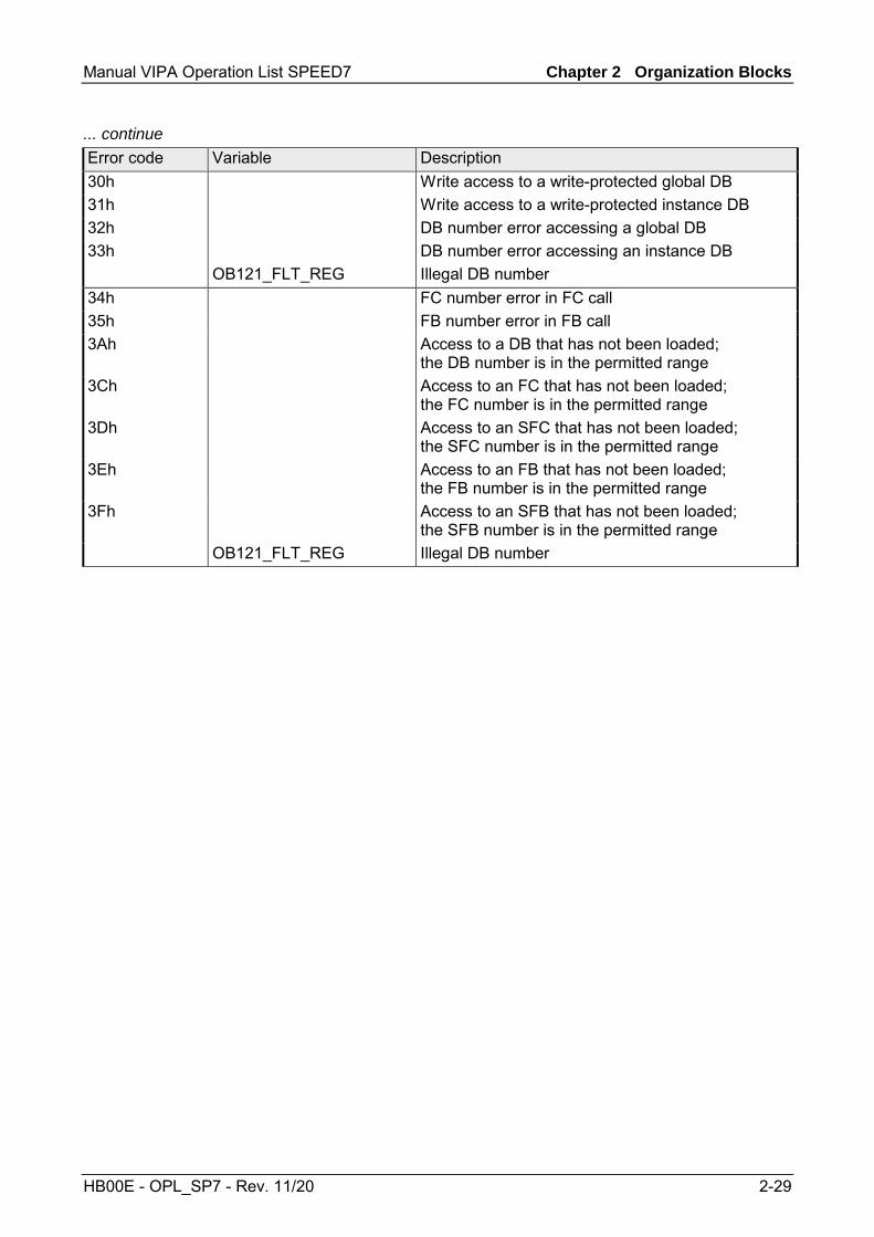
Manual VIPA Operation List SPEED7 Chapter 2 Organization Blocks
HB00E - OPL_SP7 - Rev. 11/20 2-29
... continue Error code Variable Description 30h Write access to a write-protected global DB 31h Write access to a write-protected instance DB 32h DB number error accessing a global DB 33h DB number error accessing an instance DB OB121_FLT_REG Illegal DB number 34h FC number error in FC call 35h FB number error in FB call 3Ah Access to a DB that has not been loaded;
the DB number is in the permitted range 3Ch Access to an FC that has not been loaded;
the FC number is in the permitted range 3Dh Access to an SFC that has not been loaded;
the SFC number is in the permitted range 3Eh Access to an FB that has not been loaded;
the FB number is in the permitted range 3Fh Access to an SFB that has not been loaded;
the SFB number is in the permitted range OB121_FLT_REG Illegal DB number

Chapter 2 Organization Blocks Manual VIPA Operation List SPEED7
2-30 HB00E - OPL_SP7 - Rev. 11/20
OB 122 - Periphery access Error
The operating system of the CPU calls OB 122 whenever an error occurs while accessing data on a module. For example, if the CPU detects a read error when accessing data on an I/O module, the operating system calls OB 122. If OB 122 is not programmed, the CPU changes from the RUN mode to the STOP mode. OB 122 is executed in the same priority class as the interrupted block. So you have read/write access to the registers of the interrupted block. The CPU provides the following SFCs for masking and unmasking start events for OB 122: • SFC 36 MASK_FLT masks specific error codes • SFC 37 DMASK_FLT unmasks the error codes that were masked by
SFC 36 • SFC 38 READ_ERR reads the error register The following table describes the start information of the OB 122 with default names of the variables and its data types:
Variable Type Description OB122_EV_CLASS BYTE Event class and identifiers: 29h OB122_SW_FLT BYTE Error code:
42h: I/O access error - reading 43h: I/O access error - writing
OB122_PRIORITY BYTE Priority class: Priority class of the OB where the error occurred
OB122_OB_NUMBR BYTE OB number (122) OB122_BLK_TYPE BYTE No valid number is entered here OB122_MEM_AREA BYTE Memory area and access type:
Bit 3 ... 0: memory area 0: I/O area; 1: Process image of the inputs 2: Process image of the outputs Bit 7 ... 4: access type: 0: Bit access, 1: Byte access, 2: Word access, 3: Dword access
OB122_MEM_ADDR WORD Memory address where the error occurred OB122_BLK_NUM WORD No valid number is entered here OB122_PGR_ADDR WORD No valid number is entered here OB122_DATE_TIME DATE_AND_TIME Date and time of day when the OB was called
Information to access the local data can be found at the description of the OB 1.
Description
Masking of start events
Local data

Manual VIPA Operation List SPEED7 Chapter 3 Integrated SFBs
HB00E - OPL_SP7 - Rev. 11/20 3-1
Chapter 3 Integrated SFBs
Here the description of the integrated function blocks of the VIPA SPEED7 CPUs may be found.
Topic Page Chapter 3 Integrated SFBs............................................................... 3-1
Overview .............................................................................................. 3-2 SFB 0 - CTU - Up-counter .................................................................... 3-3 SFB 1 - CTD - Down-counter................................................................ 3-4 SFB 2 - CTUD - Up-Down counter........................................................ 3-5 SFB 3 - TP - Create pulse .................................................................... 3-7 SFB 4 - TON - Create turn-on delay ..................................................... 3-9 SFB 5 - TOF - Create turn-off delay.................................................... 3-11 SFB 32 - DRUM - Realize a step-by-step switch ................................ 3-13 SFB 31 - NOTIFY_8P - Messages without Acknowl. Display (8x) ....... 3-18 SFB 33 - ALARM - Messages with Acknowledgment Display............. 3-21 SFB 34 - ALARM_8 - Messages without Associated Values (8x) ....... 3-24 SFB 35 - ALARM_8P - Messages with Associated Values (8x) .......... 3-26 SFB 36 - NOTIFY - Messages without Acknowledgment Display ....... 3-29 SFB 47 - COUNT - Counter controlling............................................... 3-31 SFB 52 - RDREC - Reading a Data Record from a DP-V1 slave........ 3-35 SFB 53 - WRREC - Writing a Data Record in a DP-V1 slave.............. 3-37 SFB 54 - RALRM - Receiving an interrupt from a DP-V1 slave........... 3-39
Overview
Content

Chapter 3 Integrated SFBs Manual VIPA Operation List SPEED7
3-2 HB00E - OPL_SP7 - Rev. 11/20
Overview
The system program of the CPU offers you some additional functions that you may use by calling FBs, FCs or OBs. Those additional functions are part of the system program and don't use any work memory. Although the additional functions may be requested, they cannot be read or altered. The calling of an additional function via FB, FC or OB is registered as block change and influences the nesting depth for blocks.
The following system function blocks (SFBs) are available:
SFB Label Description L-Stack SFB 0 1) CTU Count forward 18Byte SFB 1 1) CTD Count backwards 18Byte SFB 2 1) CTUD Count forward and backwards 18Byte SFB 3 1) TP Create pulse 22Byte SFB 4 1) TON Create switch-on delay 22Byte SFB 5 1) TOF Create switch-off delay 22Byte SFB 8 USEND See FB/SFB 8 - SFB 9 URCV See FB/SFB 9 - SFB 12 BSEND See FB/SFB 12 - SFB 13 BRCV See FB/SFB 13 - SFB 14 GET See FB/SFB 14 - SFB 15 PUT See FB/SFB 15 - SFB 31 NOTIFY_8P Messages without acknowledgment display
(8 Signals) -
SFB 32 DRUM Realization of a step sequential circuit with a max. of 16 steps
-
SFB 33 ALARM Messages with acknowledgment display - SFB 34 ALARM_8 Messages without associated values (8 Signals) - SFB 35 ALARM_8P Messages with associated values (8 Signals) - SFB 36 NOTIFY Messages without acknowledgment display - SFB 47 1) COUNT Counter controlling 48Byte SFB 52 RDREC DP-V1-SFB
Reading a Data Record from a DP slave -
SFB 53 WRREC DP-V1-SFB Writing a Data Record in a DP slave
-
SFB 54 RALRM DP-V1-SFB Receiving an Interrupt from a DP slave
-
1) This function block is interruptable and does not affect the interrupt reaction time.
Note! Please note that L-Stack memory is occupied by using the above described SFB 0...5. This can be defined by the CPU parameters. The needed Space is to be found in the table above.
General
Integrated SFBs

Manual VIPA Operation List SPEED7 Chapter 3 Integrated SFBs
HB00E - OPL_SP7 - Rev. 11/20 3-3
SFB 0 - CTU - Up-counter
The SFB 0 can be used as Up-counter. Here you have the following characteristics: • If the signal at the up counter input CU changes from "0" to "1" (positive
edge), the current counter value is incremented by 1 and displayed at output CV.
• When called for the first time with R="0" the counter value corresponds to the preset value at input PV.
• When the upper limit of 32767 is reached the counter will not be incremented any further, i.e. all rising edges at input CU are ignored.
• The counter is reset to zero if reset input R has signal state "1". • Output Q has signal state "1" if CV ≥ PV. • When it is necessary that the instances of this SFB are initialized after a
warm start, then the respective instances must be initialized in OB 100 with R = 1.
Parameter Declaration Data type Memory block Description CU INPUT BOOL I, Q, M, D, L, constant Count input R INPUT BOOL I, Q, M, D, L, constant Reset input. R takes precedence
over CU. PV INPUT INT I, Q, M, D, L, constant Preset value. The effect of PV is
described under parameter Q. Q OUTPUT BOOL I, Q, M, D, L Status of the counter CV OUTPUT INT I, Q, M, D, L Current count
Count input: This counter is incremented by 1 when a rising edge (with respect to the most recent SFB call) is applied to input CU.
Reset input: The counter is reset to 0 when input R is set to "1", irrespective of the status of input CU.
Preset value: This value is the comparison value for the current counter value. Output Q indicates whether the current count is greater than or equal to the preset value PV.
Status of the counter: • Q is set to "1", if CV ≥ PV (current count ≥ preset value) • else Q = "0"
Current count: • possible values: 0 ... 32767
Description
Parameters
CU
R
PV
Q
CV

Chapter 3 Integrated SFBs Manual VIPA Operation List SPEED7
3-4 HB00E - OPL_SP7 - Rev. 11/20
SFB 1 - CTD - Down-counter
The SFB 1 can be used as Down-counter. Here you have the following characteristics: • If the signal state at the down counter input CD changes from "0" to "1"
(positive edge), the current counter value is decremented by 1 and displayed at output CV.
• When called for the first time with LOAD = "0" the counter value corresponds to the preset value at input PV.
• When the lower limit of -32767 is reached the counter will not be decremented any further, i.e. all rising edges at input CU are ignored.
• When a "1" is applied to the LOAD input then the counter is set to preset value PV irrespective of the value applied to input CD.
• Output Q has signal state "1" if CV ≤ 0. • When it is necessary that the instances of this SFB are initialized after a
warm start, then the respective instances must be initialized in OB 100 with LOAD = 1 and PV = required preset value for CV.
Parameter Declaration Data type Memory block Description CD INPUT BOOL I, Q, M, D, L, constant Count input LOAD INPUT BOOL I, Q, M, D, L, constant Load input. LOAD takes
precedence over CD. PV INPUT INT I, Q, M, D, L, constant Preset value Q OUTPUT BOOL I, Q, M, D, L Status of the counter CV OUTPUT INT I, Q, M, D, L Current count
Count input: This counter is decremented by 1 when a rising edge (with respect to the most recent SFB call) is applied to input CU. Load input: When a 1 is applied to the LOAD input then the counter is set to preset value PV irrespective of the value applied to input CD. Preset value: The counter is set to preset value PV when the input LOAD is “1”. Status of the counter: Q is set to • 1, if 0 ≥ CV (Current count value smaller/even 0) • else Q = "0" Current count: • possible values: -32 768 ... 32 767
Description
Parameters
CD
LOAD
PV
Q
CV

Manual VIPA Operation List SPEED7 Chapter 3 Integrated SFBs
HB00E - OPL_SP7 - Rev. 11/20 3-5
SFB 2 - CTUD - Up-Down counter
The SFB 2 can be used as an Up-Down counter. Here you have the following characteristics: • If the signal state at the up count input CU changes from "0" to "1"
(positive edge), the counter value is incremented by 1 and displayed at output CV.
• If the signal state at the down count input CD changes from "0" to "1" (positive edge), the counter value is decremented by 1 and displayed at output CV.
• If both counter inputs have a positive edge, the current counter value does not change.
• When the count reaches the upper limit of 32767 any further edges are ignored.
• When the count reaches the lower limit of -32768 any further edges are ignored.
• When a "1" is applied to the LOAD input then the counter is set to preset value PV.
• The counter value is reset to zero if reset input R has signal state "1". Positive signal edges at the counter inputs and signal state "1" at the load input remain without effect while input R has signal state "1".
• Output QU has signal state "1", if CV ≥ PV. • Output QD has signal state "1", if CV ≤ 0. • When it is necessary that the instances of this SFB are initialized after a
restart, then the respective instances must be initialized in OB 100 with: - when the counter is used as up-counter with R = "1" - when the counter is used as down-counter with R = 0 and LOAD = 1
and PV = preset value.
Parameter Declaration Data type Memory block Description CU INPUT BOOL I, Q, M, D, L, constant Count up input CD INPUT BOOL I, Q, M, D, L, constant Count down input R INPUT BOOL I, Q, M, D, L, constant Reset input, R takes
precedence over LOAD. LOAD INPUT BOOL I, Q, M, D, L, constant Load input, LOAD takes
precedence over CU and CD. PV INPUT INT I, Q, M, D, L, constant Preset value QU OUTPUT BOOL I, Q, M, D, L Status of the up counter QD OUTPUT BOOL I, Q, M, D, L Status of the down counter CV OUTPUT INT I, Q, M, D, L Current count
Description
Parameters

Chapter 3 Integrated SFBs Manual VIPA Operation List SPEED7
3-6 HB00E - OPL_SP7 - Rev. 11/20
Count up input: A rising edge (with respect to the most recent SFB-call) at input CU increments the counter.
Count down input: A rising edge (with respect to the most recent SFB-call) at input CD decrements the counter.
Reset input: When input R is set to "1" the counter is reset to 0, irrespective of the status of inputs CU, CD and LOAD.
Load input: When the LOAD input is set to "1" the counter is preset to the value applied to PV, irrespective of the values of inputs CU and CD.
Preset value: The counter is preset to the value applied to PV, when the LOAD input is set to 1.
Status of the down counter: • QU is set to "1", if CV ≥ PV (Current count ≥ Preset value) • else QU is 0.
Status of the down counter: • QD is set to 1", if 0 ≥ CV (Current count smaller/= 0) • else QD is 0.
Current count • possible values: -32 768 ... 32 767
CU
CD
R
LOAD
PV
QU
QD
CV

Manual VIPA Operation List SPEED7 Chapter 3 Integrated SFBs
HB00E - OPL_SP7 - Rev. 11/20 3-7
SFB 3 - TP - Create pulse
The SFB 3 can be used to generate a pulse with a pulse duration equal to PT. Here you have the following characteristics: • The pulse duration is only available in the STARTUP and RUN modes. • The pulse is started with a rising edge at input IN. • During PT time the output Q is set regardless of the input signal. • The ET output provides the time for which output Q has already been
set. The maximum value of the ET output is the value of the PT input. Output ET is reset when input IN changes to "0", however, not before the time PT has expired.
• When it is necessary that the instances of this SFB 3 are initialized after a restart, then the respective instances must be initialized in OB 100 with PT = 0 ms.
IN
Q
PT
ET
PT PT PT
Parameter Declaration Data type Memory block Description IN INPUT BOOL I, Q, M, D, L,
constant Start input
PT INPUT TIME I, Q, M, D, L, constant
Pulse duration
Q OUTPUT BOOL I, Q, M, D, L Status of the time ET OUTPUT TIME I, Q, M, D, L Expired time
Description
Time diagram
Parameters

Chapter 3 Integrated SFBs Manual VIPA Operation List SPEED7
3-8 HB00E - OPL_SP7 - Rev. 11/20
Start input: The pulse is started by a rising edge at input IN.
Pulse duration: PT must be positive. The range of these values is determined by data type TIME.
Output Q: Output Q remains active for the pulse duration PT, irrespective of the subsequent status of the input signal
Expired time: The duration for which output Q has already been active is available at output ET where the maximum value of this output can be equal to the value of PT. When input IN changes to 0 output ET is reset, however, this only occurs after PT has expired.
IN
PT
Q
ET

Manual VIPA Operation List SPEED7 Chapter 3 Integrated SFBs
HB00E - OPL_SP7 - Rev. 11/20 3-9
SFB 4 - TON - Create turn-on delay
SFB 4 can be used to delay a rising edge by period PT. Here you have the following characteristics: • The timer runs only in the STARTUP and RUN modes. • A rising edge at the IN input causes a rising edge at output Q after the
time PT has expired. Q then remains set until the IN input changes to 0 again. If the IN input changes to "0" before the time PT has expired, output Q remains set to "0".
• The ET output provides the time that has passed since the last rising edge at the IN input. Its maximum value is the value of the PT input. ET is reset when the IN input changes to "0".
• When it is necessary that the instances of this SFB are initialized after a restart, then the respective instances must be initialized in OB 100 with PT = 0 ms.
IN
Q
PT
ET
PT PT
Parameter Declaration Type Memory block Description IN INPUT BOOL I, Q, M, D, L,
constant Start input
PT INPUT TIME I, Q, M, D, L, constant
Time delay
Q OUTPUT BOOL I, Q, M, D, L Status of time ET OUTPUT TIME I, Q, M, D, L Expired time
Description
Timing diagram
Parameters
Chapter 3 Integrated SFBs Manual VIPA Operation List SPEED7
3-10 HB00E - OPL_SP7 - Rev. 11/20
Start input: The time delay is started by a rising edge at input IN. Output Q also produces a rising edge when time delay PT has expired.
Time delay: Time delay applied to the rising edge at input IN PT must be. The range of values is defined by the data type TIME.
Status of time: The time delay is started by a rising edge at input IN. Output Q also produces a rising edge when time delay PT has expired and it remains set until the level applied to input IN changes back to 0. If input IN changes to 0 before time delay PT has expired then output Q remains at "0".
Expired time: Output ET is set to the time duration that has expired since the most recent rising edge has been applied to input IN. The highest value that output ET can contain is the value of input PT. Output ET is reset when input IN changes to "0".
IN
PT
Q
ET

Manual VIPA Operation List SPEED7 Chapter 3 Integrated SFBs
HB00E - OPL_SP7 - Rev. 11/20 3-11
SFB 5 - TOF - Create turn-off delay
SFB 5 can be used to delay a falling edge by period PT. Here you have the following characteristics: • The timer runs only in the STARTUP and RUN modes. • A rising edge at the IN input causes a rising edge at output Q. A falling
edge at the IN input causes a falling edge at output Q delayed by the time PT. If the IN input changes back to "1" before the time PT has expired, output Q remains set to "1".
• The ET output provides the time that has elapsed since the last falling edge at the IN input. Its maximum value is, however the value of the PT input. ET is reset when the IN input changes to "1".
• When it is necessary that the instances of this SFB are initialized after a restart, then the respective instances must be initialized in OB 100 with PT = 0 ms.
IN
Q
PT
ET
PT PT PT
Parameter Declaration Data type Memory block Description IN INPUT BOOL I, Q, M, D, L,
constant Start input
PT INPUT TIME I, Q, M, D, L, constant
Time delay
Q OUTPUT BOOL I, Q, M, D, L Status of time ET OUTPUT TIME I, Q, M, D, L Expired time
Description
Time diagram
Parameters

Chapter 3 Integrated SFBs Manual VIPA Operation List SPEED7
3-12 HB00E - OPL_SP7 - Rev. 11/20
Start input: The time delay is started by a rising edge at input IN results in a rising edge at output Q. When a falling edge is applied to input IN output Q will also produce a falling edge when delay PT has expired. If the level at input IN changes to "1" before time delay PT has expired, then the level at output Q will remain at "1".
Time delay: Time delay applied to the falling edge at input IN PT must be. The range of values is defined by the data type TIME.
Status of time: The time delay is started by a rising edge at input IN results in a rising edge at output Q. When a falling edge is applied to input IN output Q will also produce a falling edge when delay PT has expired. If the level at input IN changes to "1" before time delay PT has expired, then the level at output Q will remain at "1".
Expired time: The time period that has expired since the most recent falling edge at input IN is available from output ET. The highest value that output ET can reach is the value of input PT. Output ET is reset when the level at input IN changes to "1".
IN
PT
Q
ET

Manual VIPA Operation List SPEED7 Chapter 3 Integrated SFBs
HB00E - OPL_SP7 - Rev. 11/20 3-13
SFB 32 - DRUM - Realize a step-by-step switch
Implementing a 16-state cycle switch using the SFB 32. Parameter DSP defines the number of the first step, parameter LST_STEP defines the number of the last step. Every step describes the 16 output bits OUT0 ... OUT15 and output parameter OUT_WORD that summarizes the output bits. The cycle switch changes to the next step when a positive edge occurs at input JOG with respect to the previous SFB-call. If the cycle switch has already reached the last step and a positive edge is applied to JOG variables Q and EOD will be set, DCC is set to 0 and SFB 32 remains at the last step until a "1" is applied to the RESET input.
The switch can also be controlled by a timer. For this purpose parameter DRUM_EN must be set to "1". The next step of the cycle switch is activated when: • the event bit EVENTi of the current step is set and • when the time defined for the current step has expired. The time is calculated as the product of time base DTBP and the timing factor that applies to the current step (from the S_PRESET field).
Note! The remaining processing time DCC in the current step will only be decremented if the respective event bit EVENTi is set.
If input RESET is set to "1" when the call is issued to SFB 32 then the cycle switch changes to the step that you have specified as a number at input DSP.
Description
Time controlled switching

Chapter 3 Integrated SFBs Manual VIPA Operation List SPEED7
3-14 HB00E - OPL_SP7 - Rev. 11/20
Note! Special conditions apply if parameter DRUM_EN is set to "1": • timer-controlled cycle switching, if EVENTi = "1" with
DSP = i = LST_STEP. • event-controlled cycle switching by means of event bits EVENTi,
when DTBP = "0". In addition it is possible to advance the cycle switch at any time (even if DRUM_EN = "1") by means of the JOG input.
When this module is called for the first time the RESET input must be set to "1". If the cycle switch has reached the last step and the processing time defined for this step has expired, then outputs Q and EOD will be set and SFB 32 will remain at the last step until the RESET input is set to "1". The SFB 32 is only active in operating modes RESTART and RUN. If SFB 32 must be initialized after a warm start it must be called from OB 100 with RESET = "1".
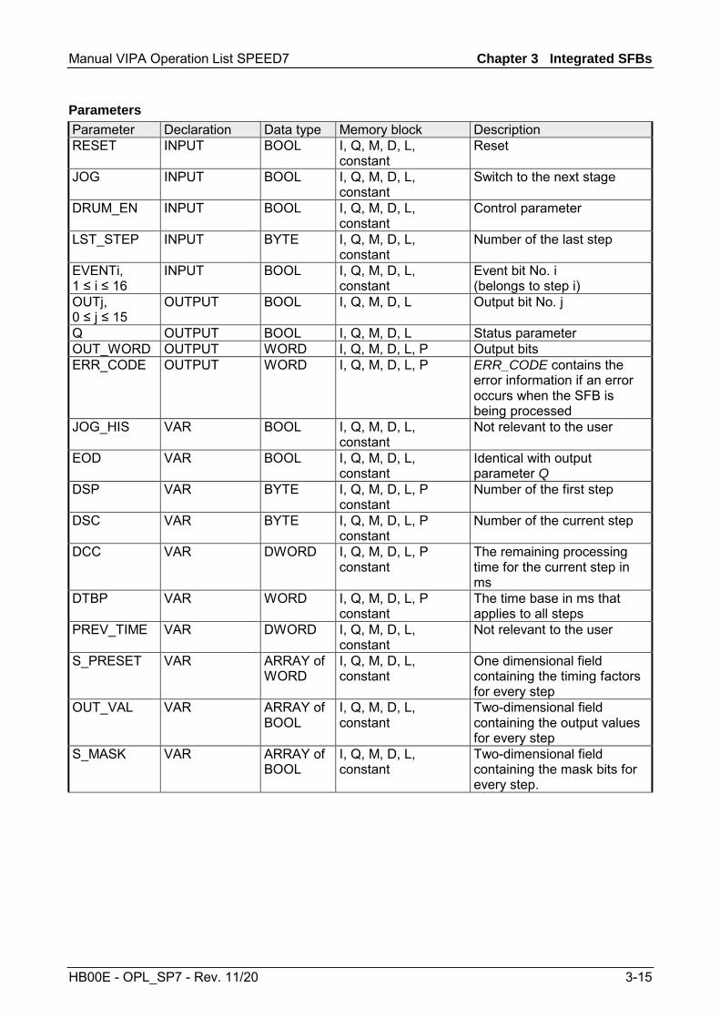
Manual VIPA Operation List SPEED7 Chapter 3 Integrated SFBs
HB00E - OPL_SP7 - Rev. 11/20 3-15
Parameter Declaration Data type Memory block Description RESET INPUT BOOL I, Q, M, D, L,
constant Reset
JOG INPUT BOOL I, Q, M, D, L, constant
Switch to the next stage
DRUM_EN INPUT BOOL I, Q, M, D, L, constant
Control parameter
LST_STEP INPUT BYTE I, Q, M, D, L, constant
Number of the last step
EVENTi, 1 ≤ i ≤ 16
INPUT BOOL I, Q, M, D, L, constant
Event bit No. i (belongs to step i)
OUTj, 0 ≤ j ≤ 15
OUTPUT BOOL I, Q, M, D, L Output bit No. j
Q OUTPUT BOOL I, Q, M, D, L Status parameter OUT_WORD OUTPUT WORD I, Q, M, D, L, P Output bits ERR_CODE OUTPUT WORD I, Q, M, D, L, P ERR_CODE contains the
error information if an error occurs when the SFB is being processed
JOG_HIS VAR BOOL I, Q, M, D, L, constant
Not relevant to the user
EOD VAR BOOL I, Q, M, D, L, constant
Identical with output parameter Q
DSP VAR BYTE I, Q, M, D, L, P constant
Number of the first step
DSC VAR BYTE I, Q, M, D, L, P constant
Number of the current step
DCC VAR DWORD I, Q, M, D, L, P constant
The remaining processing time for the current step in ms
DTBP VAR WORD I, Q, M, D, L, P constant
The time base in ms that applies to all steps
PREV_TIME VAR DWORD I, Q, M, D, L, constant
Not relevant to the user
S_PRESET VAR ARRAY of WORD
I, Q, M, D, L, constant
One dimensional field containing the timing factors for every step
OUT_VAL VAR ARRAY of BOOL
I, Q, M, D, L, constant
Two-dimensional field containing the output values for every step
S_MASK VAR ARRAY of BOOL
I, Q, M, D, L, constant
Two-dimensional field containing the mask bits for every step.
Parameters
Chapter 3 Integrated SFBs Manual VIPA Operation List SPEED7
3-16 HB00E - OPL_SP7 - Rev. 11/20
Reset: The cycle switch is reset if this is set to "1". RESET must be set to "1" when the initial call is issued to the block. A rising edge (with respect to the last SFB call) increments the cycle switch to the next stage if the cycle switch has not yet reached the last step. This is independent of the value of DRUM_EN. Control parameter that determines whether timer-controlled cycle switching to the next step should be enabled or not ("1": enable timer-controlled increments). Number of the last step: • possible values: 1 ... 16 Event bit No. i (belonging to step i) Output bit No. j (identical with bit No. j of OUT_WORD) Status parameter specifying whether the processing time that you have defined for the last step has expired. Output bits summarized in a single variable. ERR_CODE contains the error information if an error occurs when the SFB is being processed. Not relevant to the user: input parameter JOG of the previous SFB-call. Identical with output parameter Q Number of the first step: • possible values 1 ... 16 Number of the current step The remaining processing time for the current step in ms (only relevant if DRUM_EN = "1" and if the respective event bit = "1") The time base in ms that applies to all steps. Not relevant to the user: system time of the previous SFB call. One-dimensional field containing the timing factors for every step. • Meaningful indices are: [1 ... 16]. In this case S_PRESET [x] contains the timing factor of step x.
RESET
JOG
DRUM_EN
LST_STEP
EVENTi, 1≤≤≤≤i≤≤≤≤16 OUTj 0≤≤≤≤j≤≤≤≤15 Q
OUT_WORD
ERR_CODE
JOG_HIS
EOD
DSP
DSC
DCC
DTBP
PREV_TIME
S_PRESET

Manual VIPA Operation List SPEED7 Chapter 3 Integrated SFBs
HB00E - OPL_SP7 - Rev. 11/20 3-17
Two-dimensional field containing the output values for every step if you have not masked these by means of S_MASK. • Meaningful indices are: [1 ... 16, 0 ... 15]. In this case OUT_VAL [x, y] contains the value that is assigned to output bit OUTy in step x. Two-dimensional field containing the mask bits for every step. • Meaningful indices are: [1 ... 16, 0 ... 15]. In this case S_MASK [x, y] contains the mask bit for the value y of step x. Significance of the mask bits: • 0: the respective value of the previous step is assigned to the output bit • 1: the respective value of OUT_VAL is assigned to the output bit. ERR_CODE When an error occurs the status of SFB 32 remains at the current value and output ERR_CODE contains one of the following error codes:
ERR_CODE Description 0000h No error has occurred 8081h illegal value for LST_STEP 8082h illegal value for DSC 8083h illegal value for DSP 8084h The product DCC = DTBP x S_PRESET[DSC ] exceeds
the value 231-1 (appr. 24.86 Days)
OUT_VAL
S_MASK
Error information

Chapter 3 Integrated SFBs Manual VIPA Operation List SPEED7
3-18 HB00E - OPL_SP7 - Rev. 11/20
SFB 31 - NOTIFY_8P - Messages without Acknowl. Display (8x)
Generating block related messages without acknowledgement display for 8 signals. SFB 31 NOTIFY_8P represents an extension of SFB 36 "NOTIFY" to 8 signals. A message is generated if at least one signal transition has been detected. A message is always generated at the initial call of SFB 31. All 8 signal are allocated a common message number that is split into 8 sub-messages on the displaying device. One memory with two memory blocks is available for each instance of SFB 31 NOTIFY_8P. For information on saving signal transitions to intermediate memory refer to the section "Signal transition detection" in the Introduction to Generating Block Related Messages with SFBs. The displaying device shows the last two signal transitions, irrespective of message loss.
Note! Before you call SFB 31 NOTIFY_8P in a CPU, you must insure that all connected displaying devices know this block. More information about this may be found in the manuals of the components used.
Parameter Declaration Data type Memory block Description SIG_i, INPUT BOOL I, Q, M, D, L. i-th signal to be monitored ID INPUT WORD Constant
(I, Q, M, D, L) Data channel for messages: EEEEh ID is evaluated only at the initial call.
EV_ID INPUT DWORD Constant (I, Q, M, D, L)
Message number (not permitted: 0)
SEVERITY INPUT WORD Constant (I, Q, M, D, L)
Weighting of the event
DONE OUTPUT BOOL I, Q, M, D, L Status parameter DONE: Message generation completed.
ERROR OUTPUT BOOL I, Q, M, D, L Status parameter ERROR STATUS OUTPUT WORD I, Q, M, D, L Status parameter STATUS:
Display of an error information SD_i IN_OUT ANY I, Q, M, D, T, C i-th associated value
Description
Parameters

Manual VIPA Operation List SPEED7 Chapter 3 Integrated SFBs
HB00E - OPL_SP7 - Rev. 11/20 3-19
i-th signal to be monitored. It is valid 1 ≤ i ≤ 8. Data channel for messages: EEEEh. ID is evaluated only at the initial call. Message number (not permitted: 0) EV_ID is only evaluated at the first call. Subsequently, the message number used for the first call applies to every call of SFB with the corresponding instance DB. The Siemens STEP®7 programming tool assigns the message number automatically to ensure consistency of the message numbers. The message numbers within a user program must be unique. Weighting of the event. Here the value 0 is the highest weighting. This parameter is irrelevant for processing the message. Possible: 0 ... 127 (Default value: 64) Status parameter DONE: Message generation completed. i-th associated value. It is valid 1 ≤ i ≤ maxNumber. The max. number may be found in the technical data of your CPU. Permitted are only data of the type BOOL, (not permitted: bit field), BYTE, CHAR, WORD, INT, DWORD, DINT, REAL, DATE, TOD, TIME, S5TIME, DATE_AND _TIME. Note: When the ANY pointer accesses a DB, the DB always must be specified. (e.g.: P# DB10.DBX5.0 Byte 10)
SIG_i
ID
EV_ID
SEVERITY
DONE
SD_i
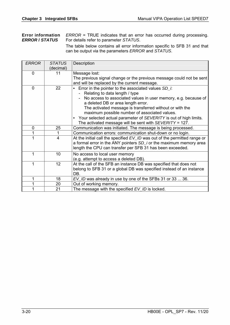
Chapter 3 Integrated SFBs Manual VIPA Operation List SPEED7
3-20 HB00E - OPL_SP7 - Rev. 11/20
ERROR = TRUE indicates that an error has occurred during processing. For details refer to parameter STATUS. The table below contains all error information specific to SFB 31 and that can be output via the parameters ERROR and STATUS.
ERROR STATUS (decimal)
Description
0 11 Message lost: The previous signal change or the previous message could not be sent and will be replaced by the current message.
0 22 • Error in the pointer to the associated values SD_i: - Relating to data length / type - No access to associated values in user memory, e.g. because of
a deleted DB or area length error. The activated message is transferred without or with the maximum possible number of associated values.
• Your selected actual parameter of SEVERITY is out of high limits. The activated message will be sent with SEVERITY = 127.
0 25 Communication was initiated. The message is being processed. 1 1 Communication errors: communication shut-down or no login. 1 4 At the initial call the specified EV_ID was out of the permitted range or
a formal error in the ANY pointers SD_i or the maximum memory area length the CPU can transfer per SFB 31 has been exceeded.
1 10 No access to local user memory (e.g. attempt to access a deleted DB).
1 12 At the call of the SFB an instance DB was specified that does not belong to SFB 31 or a global DB was specified instead of an instance DB.
1 18 EV_ID was already in use by one of the SFBs 31 or 33 ... 36. 1 20 Out of working memory. 1 21 The message with the specified EV_ID is locked.
Error information ERROR / STATUS

Manual VIPA Operation List SPEED7 Chapter 3 Integrated SFBs
HB00E - OPL_SP7 - Rev. 11/20 3-21
SFB 33 - ALARM - Messages with Acknowledgment Display
Generating block-related messages with acknowledgment SFB 33 ALARM monitors a signal: • Default mode (that is, acknowledgement triggered reporting is disabled):
The block generates a message both on a positive edge (event entering state) and on a negative edge (event leaving state). You can have associated values sent with the message.
• Acknowledgement triggered reporting is enabled: After an incoming message is generated for the signal, the block will no longer generate messages until you have acknowledged this incoming message on a displaying device.
When the SFB is first called, a message with the current signal state is sent. The message is sent to all stations logged on for this purpose. Once your acknowledgment has been received from a logged on display device, the acknowledgment information is passed on to all other stations logged on for this purpose. One message memory with 2 memory blocks is available for each instance of SFB 33 ALARM. SFB 33 ALARM complies with the IEC 1131-5 standard.
Parameter Declaration Data type Memory block Description EN_R INPUT BOOL I, Q, M, D, L,
Constant Control parameter
SIG INPUT BOOL I, Q, M, D, L The signal to be monitored ID INPUT WORD Constant
(I, Q, M, D, L) Data channel for messages: EEEEh ID is only evaluated at the first call.
EV_ID INPUT DWORD Constant (I, Q, M, D, L)
Message number (0 not permitted)
SEVERITY INPUT WORD Constant (I, Q, M, D, L)
Weighting of the event
DONE OUTPUT BOOL I, Q, M, D, L DONE status parameter: Generation of message completed
ERROR OUTPUT BOOL I, Q, M, D, L ERROR status parameter STATUS OUTPUT WORD I, Q, M, D, L STATUS parameter:
Displays error information ACK_DN OUTPUT BOOL I, Q, M, D, L Event leaving state was acknowledged ACK_UP OUTPUT BOOL I, Q, M, D, L Event entering state was acknowledged SD_i, IN_OUT ANY I, Q, M, D, T, C i-th associated value
Description
Parameters

Chapter 3 Integrated SFBs Manual VIPA Operation List SPEED7
3-22 HB00E - OPL_SP7 - Rev. 11/20
Control parameter (enabled to receive) that decides whether the outputs ACK_UP and ACK_DN are updated at the first block call (EN_R = 1) or not (EN_R = 0). If EN_R = 0 the output parameters ACK_UP and ACK_DN remain unchanged. Signal to be monitored. Data channel for messages: EEEEh. ID is evaluated only at the initial call. Message number (not permitted: 0) EV_ID is only evaluated at the first call. Subsequently, the message number used for the first call applies to every call of SFB with the corresponding instance DB. The Siemens STEP®7 programming tool assigns the message number automatically to ensure consistency of the message numbers. The message numbers within a user program must be unique. Weighting of the event. Here the value 0 is the highest weighting. This parameter is irrelevant for processing the message. Possible: 0 ... 127 (Default value: 64) Status parameter DONE: Message generation completed. The ACK_DN output is reset at the negative edge. It is set when your acknowledgment of the event leaving the state is received from a logged on display device. The ACK_UP output is reset at the rising edge. It is set when your acknowledgment of the event entering the state has arrived from a logged on display device. i-th associated value. It is valid 1 ≤ i ≤ maxNumber. The max. number may be found in the technical data of your CPU. Permitted are only data of the type BOOL, (not permitted: bit field), BYTE, CHAR, WORD, INT, DWORD, DINT, REAL, DATE, TOD, TIME, S5TIME, DATE_AND _TIME. Note: When the ANY pointer accesses a DB, the DB always must be specified. (e.g.: P# DB10.DBX5.0 Byte 10)
EN_R
SIG
ID
EV_ID
SEVERITY
DONE
ACK_DN
ACK_UP
SD_i

Manual VIPA Operation List SPEED7 Chapter 3 Integrated SFBs
HB00E - OPL_SP7 - Rev. 11/20 3-23
ERROR = TRUE indicates that an error has occurred during processing. For details refer to parameter STATUS. The following table contains all the error information specific to SFB 33 that can be output with the ERROR and STATUS parameters.
ERROR STATUS (decimal)
Description
0 11 Message lost: the previous signal change or the previous message could not be sent and will be replaced by the current message.
0 22 • Error in the pointer to the associated values SD_i: - Involving the data length or the data type - Associated values in the user memory not accessible, for
example, due to deleted DB or area length error. The activated message is sent without associated values.
• The actual parameter you have selected for SEVERITY is higher than the permitted range. The activated message will be sent with SEVERITY=127.
0 25 Communication was initiated. The message is being processed. 1 1 Communications problems: connection abort or no logon
With acknowledgment-triggered reporting active: temporary display, if no display devices support acknowledgment-triggered reporting
1 4 At the first call: the specified EV_ID is outside the permitted range or the ANY pointer SD_i has a formal error or the maximum memory area that can be sent for the CPU per SFB 33 was exceeded.
1 10 Access to local user memory not possible (for example, access to a deleted DB)
1 12 When the SFB was called: an instance DB that does not belong to SFB 33 was specified a shared DB instead of an instance DB was specified.
1 18 EV_ID was already being used by one of the SFBs 31 or 33 ... 36. 1 20 Not enough working memory. 1 21 The message with the specified EV_ID is disabled
Note! After the first block call, the ACK_UP and ACK_DN outputs have the value 1 and it is assumed that the previous value of the SIG input was 0.
Error information ERROR / STATUS

Chapter 3 Integrated SFBs Manual VIPA Operation List SPEED7
3-24 HB00E - OPL_SP7 - Rev. 11/20
SFB 34 - ALARM_8 - Messages without Associated Values (8x)
Generating block-related messages without associated values for 8 signals. SFB 34 ALARM_8 is identical to SFB 35 ALARM_8P except that it does not have the associated values SD_1 through SD_10.
Parameter Declaration Data type Memory block Description EN_R INPUT BOOL I, Q, M, D, L,
constant Control parameter
SIG_i INPUT BOOL I, Q, M, D, L i-th signal to be monitored ID INPUT WORD Constant
(I, Q, M, D, L) Data channel for messages: EEEEh ID is only evaluated at the first call.
EV_ID INPUT DWORD Constant (I, Q, M, D, L)
Message number (0 not permitted)
SEVERITY INPUT WORD Constant (I, Q, M, D, L)
Weighting of the event
DONE OUTPUT BOOL I, Q, M, D, L DONE status parameter: Generation of message completed
ERROR OUTPUT BOOL I, Q, M, D, L ERROR status parameter STATUS OUTPUT WORD I, Q, M, D, L STATUS parameter:
Displays error information ACK_STATE OUTPUT BOOL I, Q, M, D, L Bit field acknowledgement status of all 8
messages Control parameter (enabled to receive) that decides whether the output ACK_STATE is updated (EN_R = 1) when the block is called or not (EN_R = 0). i-th Signal to be monitored. It is valid 1 ≤ i ≤ 8. Data channel for messages: EEEEh. ID is evaluated only at the initial call. Message number (not permitted: 0) EV_ID is only evaluated at the first call. Subsequently, the message number used for the first call applies to every call of SFB with the corresponding instance DB. The Siemens STEP®7 programming tool assigns the message number automatically to ensure consistency of the message numbers. The message numbers within a user program must be unique. Weighting of the event. Here the value 0 is the highest weighting. This parameter is irrelevant for processing the message. Possible: 0 ... 127 (Default value: 64)
Description
Parameters
EN_R
SIG_i
ID
EV_ID
SEVERITY
Manual VIPA Operation List SPEED7 Chapter 3 Integrated SFBs
HB00E - OPL_SP7 - Rev. 11/20 3-25
Status parameter DONE, Message generation completed. Bit field with the current acknowledgment status of all 8 messages Bit 7 ... 0: incoming event of SIG_1 ... SIG_8 Bit 15 ... 8: outgoing event of SIG_1 ... SIG_8 (1: Event acknowledged, 0: Event not acknowledged) Initialization status: FFFFh, this means, all incoming and outgoing events have been acknowledged.
ERROR = TRUE indicates that an error has occurred during processing. For details refer to parameter STATUS. The following table contains all the error information specific to SFB 34 that can be output with the ERROR and STATUS parameters.
ERROR STATUS (decimal)
Description
0 11 Message lost: the previous signal change or the previous message could not be sent and will be replaced by the current message.
0 22 The actual parameter you have selected for SEVERITY is higher than the permitted range. The activated message is sent with SEVERITY=127.
0 25 Communication was initiated. The message is being processed. 1 1 Communications problems: connection abort or no logon With
acknowledgment-triggered reporting active: temporary display, if no display devices support acknowledgment-triggered reporting
1 4 At the first call, the specified EV_ID is outside the permitted range. 1 10 Access to local user memory not possible
(for example, access to a deleted DB) 1 12 When the SFB was called an instance DB that does not belong to
SFB 34 was specified or a shared DB instead of an instance DB was specified.
1 18 EV_ID was already being used by one of the SFBs 31 or 33 ... 36. 1 20 Not enough working memory. 1 21 The message with the specified EV_ID is disabled
Note! After the first block call. all the bits of the ACK_STATE output are set and it is assumed that the previous values of inputs SIG_i, 1≤ i ≤ 8 were 0.
DONE
ACK_STATE
Error information ERROR / STATUS

Chapter 3 Integrated SFBs Manual VIPA Operation List SPEED7
3-26 HB00E - OPL_SP7 - Rev. 11/20
SFB 35 - ALARM_8P - Messages with Associated Values (8x)
Generating block-related messages with associated values for 8 signals. SFB 35 ALARM_8P represents a linear extension of SFB 33 ALARM to 8 signals. As long as you have not enabled acknowledgement triggered reporting, a message will always be generated when a signal transition is detected at one or more signals (exception: a message is always sent at the first block call). All 8 signals have a common message ID that is split 8 individual messages on the display device. You can acknowledge each individual message separately or a group of messages. You can use the ACK_STATE output parameter to process the acknowledgment state of the individual messages in your program. If you disable or enable a message of an ALARM_8P block, this always affects the entire ALARM_8P block. Disabling and enabling of individual signals is not possible. One message memory with 2 memory blocks is available for each instance of SFB35 ALARM_8P.
Parameter Declaration Data type Memory block Description EN_R INPUT BOOL I, Q, M, D, L,
Constant Control parameter
SIG_i INPUT BOOL I, Q, M, D, L i-th signal to be monitored ID INPUT WORD Constant
(I, Q, M, D, L) Data channel for messages: EEEEh ID is only evaluated at the first call.
EV_ID INPUT DWORD Constant (I, Q, M, D, L)
Message number (0 not permitted)
SEVERITY INPUT WORD Constant (I, Q, M, D, L)
Weighting of the event
DONE OUTPUT BOOL I, Q, M, D, L DONE status parameter: Generation of message completed
ERROR OUTPUT BOOL I, Q, M, D, L ERROR status parameter STATUS OUTPUT WORD I, Q, M, D, L STATUS parameter:
Displays error information ACK_STATE OUTPUT WORD I, Q, M, D, L Bit field acknowledgment status of all 8
messages SD_j IN_OUT ANY I, Q, M, D, T, C i-th associated value
Description
Parameters

Manual VIPA Operation List SPEED7 Chapter 3 Integrated SFBs
HB00E - OPL_SP7 - Rev. 11/20 3-27
Control parameter (enabled to receive) that decides whether the output ACK_STATE is updated (EN_R = 1) when the block is called or not (EN_R = 0). i-th Signal to be monitored. It is valid 1 ≤ i ≤ 8. Data channel for messages: EEEEh. ID is evaluated only at the initial call. Message number (not permitted: 0) EV_ID is only evaluated at the first call. Subsequently, the message number used for the first call applies to every call of SFB with the corresponding instance DB. The Siemens STEP®7 programming tool assigns the message number automatically to ensure consistency of the message numbers. The message numbers within a user program must be unique. Weighting of the event. Here the value 0 is the highest weighting. This parameter is irrelevant for processing the message. Possible: 0 ... 127 (Default value: 64) Status parameter DONE: Message generation completed. Bit field with the current acknowledgment status of all 8 messages Bit 7 ... 0: incoming event of SIG_1 ... SIG_8 Bit 15 ... 8: outgoing event of SIG_1 ... SIG_8 (1: Event acknowledged, 0: Event not acknowledged) Initialization status: FFFFh, this means, all incoming and outgoing events have been acknowledged. i-th associated value. It is valid 1 ≤ i ≤ maxNumber. The max. number may be found in the technical data of your CPU. Permitted are only data of the type BOOL, (not permitted: bit field), BYTE, CHAR, WORD, INT, DWORD, DINT, REAL, DATE, TOD, TIME, S5TIME, DATE_AND _TIME. Note: When the ANY pointer accesses a DB, the DB always must be specified. (e.g.: P# DB10.DBX5.0 Byte 10)
EN_R
SIG_i
ID
EV_ID
SEVERITY
DONE
ACK_STATE
SD_i

Chapter 3 Integrated SFBs Manual VIPA Operation List SPEED7
3-28 HB00E - OPL_SP7 - Rev. 11/20
ERROR = TRUE indicates that an error has occurred during processing. For details refer to parameter STATUS. The following table contains all the error information specific to SFB 35 that can be output with the ERROR and STATUS parameters.
ERROR STATUS (decimal)
Description
0 11 Message lost: the previous signal change or the previous message could not be sent and will be replaced by the current message.
0 22 • Error in the pointer to the associated values SD_i: - relating to the data length or the data type - no access to associated values in user memory, for example, due to deleted DB or area length error. The activated message is sent without associated values.
• The actual parameter you have selected for SEVERITY is higher than the permitted range. The activated message will be sent with SEVERITY=127.
0 25 Communication was initiated. The message is being processed. 1 1 Communications problems: connection abort or no logon With
acknowledgment-triggered reporting active: temporary display, if no display devices support acknowledgment-triggered reporting
1 4 At the first call: the specified EV_ID is outside the permitted range or the ANY pointer SD_i has a formal error or the maximum memory area that can be sent for the CPU per SFB 35 was exceeded
1 10 Access to local user memory not possible (for example, access to a deleted DB)
1 12 When the SFB was called an instance DB that does not belong to SFB 35 was specified a shared DB instead of an instance DB was specified.
1 18 EV_ID was already being used by one of the SFBs 31 or 33 ... 36. 1 20 Not enough working memory. 1 21 The message with the specified EV_ID is disabled.
Note! After the first block call. all the bits of the ACK_STATE output are set and it is assumed that the previous values of inputs SIG_i, 1≤ i ≤ 8 were 0.
Error information ERROR / STATUS

Manual VIPA Operation List SPEED7 Chapter 3 Integrated SFBs
HB00E - OPL_SP7 - Rev. 11/20 3-29
SFB 36 - NOTIFY - Messages without Acknowledgment Display
Generating block-related messages without acknowledgment display. SFB 36 NOTIFY monitors a signal. It generates a message both on a rising edge (event entering state) and on a falling edge (event leaving state) with associated values. When the SFB is first called, a message with the current signal state is sent. The associated values are queried when the edge is detected and assigned to the message.
Parameter Declaration Data type Memory block Description SIG INPUT BOOL I, Q, M, D, L The signal to be monitored. ID INPUT WORD Constant
(I, Q, M, D, L) Data channel for messages: EEEEh ID is only evaluated at the first call.
EV_ID INPUT DWORD Constant (I, Q, M, D, L)
Message number (0 not permitted)
SEVERITY INPUT WORD Constant (I, Q, M, D, L)
Weighting of the event
DONE OUTPUT BOOL I, Q, M, D, L DONE status parameter: Generation of message completed
ERROR OUTPUT BOOL I, Q, M, D, L ERROR status parameter STATUS OUTPUT WORD I, Q, M, D, L STATUS parameter:
Displays error information SD_i IN_OUT ANY I, Q, M, D, T, C i-th associated value
Signal to be monitored. Data channel for messages: EEEEh. ID is evaluated only at the initial call. EV_ID is only evaluated at the first call. Subsequently, the message number used for the first call applies to every call of SFB with the corresponding instance DB. The Siemens STEP®7 programming tool assigns the message number automatically to ensure consistency of the message numbers. The message numbers within a user program must be unique. Weighting of the event. Here the value 0 is the highest weighting. This parameter is irrelevant for processing the message. Possible: 0 ... 127 (Default value: 64)
Description
Parameters
SIG
ID
EV_ID
SEVERITY
Chapter 3 Integrated SFBs Manual VIPA Operation List SPEED7
3-30 HB00E - OPL_SP7 - Rev. 11/20
Status parameter DONE, Message generation completed. i-th associated value. It is valid 1 ≤ i ≤ maxNumber. The max. number may be found in the technical data of your CPU. Permitted are only data of the type BOOL, (not permitted: bit field), BYTE, CHAR, WORD, INT, DWORD, DINT, REAL, DATE, TOD, TIME, S5TIME, DATE_AND _TIME. Note: When the ANY pointer accesses a DB, the DB always must be specified. (e.g.: P# DB10.DBX5.0 Byte 10)
The following table contains all the error information specific to SFB 36 that can be output with the ERROR and STATUS parameters.
ERROR STATUS (decimal)
Description
0 11 Message lost: the previous signal change or the previous message could not be sent and will be replaced by the current message.
0 22 • Error in the pointer to the associated values SD_i: - Relating to data length / type - No access to associated values in user memory, e.g. because of a
deleted DB or area length error. The activated message is transferred without or with the maximum possible number of associated values.
• Your selected actual parameter of SEVERITY is out of high limits. The activated message will be sent with SEVERITY = 127.
0 25 Communication was initiated. The message is being processed. 1 1 Communications problems: connection abort or no logon 1 4 At the first call the specified EV_ID is outside the permitted range or the
ANY pointer SD_i has a formal error or the maximum memory area that can be sent for the CPU per SFB 36 was exceeded.
1 10 Access to local user memory not possible (for example, access to a deleted DB)
1 12 When the SFB was called an instance DB that does not belong to SFB 33 was specified or a shared DB instead of an instance DB was specified.
1 18 EV_ID was already being used by one of the SFBs 31 or 33 ... 36. 1 20 Not enough working memory. 1 21 The message with the specified EV_ID is disabled.
DONE
SD_i
Error information ERROR / STATUS

Manual VIPA Operation List SPEED7 Chapter 3 Integrated SFBs
HB00E - OPL_SP7 - Rev. 11/20 3-31
SFB 47 - COUNT - Counter controlling
The SFC 47 is a specially developed block for the CPU 31xSC for controlling of the counters. The SFB is to be called with the corresponding instance DB. Here the parameters of the SFB are stored. With the SFB COUNT (SFB 47) you have following functional options: • Start/Stop the counter via software gate SW_GATE • Enable/control digital output DO • Read the status bit • Read the actual count and latch value • Request to read/write internal counter registers
Name Data type Address (Instance-DB)
Default value Comment
LADDR WORD 0.0 300h This parameter is not evaluated. Always the internal I/O periphery is addressed.
CHANNEL INT 2.0 0 Channel number SW_GATE BOOL 4.0 FALSE Enables the Software gate CTRL_DO BOOL 4.1 FALSE Enables the output
False: Standard Digital Output SET_DO BOOL 4.2 FALSE Parameter is not evaluated JOB_REQ BOOL 4.3 FALSE Initiates the job (edge 0-1) JOB_ID WORD 6.0 0 Job ID JOB_VAL DINT 8.0 0 Value for write jobs STS_GATE BOOL 12.0 FALSE Status of the internal gate STS_STRT BOOL 12.1 FALSE Status of the hardware gate STS_LTCH BOOL 12.2 FALSE Status of the latch input STS_DO BOOL 12.3 FALSE Status of the output STS_C_DN BOOL 12.4 FALSE Status of the down-count
Always indicates the last direction of count. After the first SFB call STS_C_DNis set FALSE.
STS_C_UP BOOL 12.5 FALSE Status of the up-count Always indicates the last direction of count. After the first SFB call STS_C_UPis set TRUE.
COUNTVAL DINT 14.0 0 Actual count value LATCHVAL DINT 18.0 0 Actual latch value JOB_DONE BOOL 22.0 TRUE New job can be started JOB_ERR BOOL 22.1 FALSE Job error JOB_STAT WORD 24.0 0 Job error ID
Overview
Parameters
Chapter 3 Integrated SFBs Manual VIPA Operation List SPEED7
3-32 HB00E - OPL_SP7 - Rev. 11/20
Name Data type Address (Instance DB)
Default value Comment
RES00 BOOL 26.0 FALSE reserved RES01 BOOL 26.1 FALSE reserved RES02 BOOL 26.2 FALSE reserved STS_CMP BOOL 26.3 FALSE Comparator Status *)
Status bit STS_CMP indicates that the comparison condition of the comparator is or was reached. STS_CMP also indicates that the output was set. (STS_DO = TRUE).
RES04 BOOL 26.4 FALSE reserved STS_OFLW BOOL 26.5 FALSE Overflow status *) STS_UFLW BOOL 26.6 FALSE Underflow status *) STS_ZP BOOL 26.7 FALSE Status of the zero mark *)
The bit is only set when counting without main direction. Indicates the zero mark. This is also set when the counter is set to 0 or if is start counting.
JOB_OVAL DINT 28.0 Output value for read request. RES10 BOOL 32.0 FALSE reserved RES11 BOOL 32.1 FALSE reserved RES_STS BOOL 32.2 FALSE Reset status bits:
Resets the status bits: STS_CMP, STS_OFLW, STS_ZP. The SFB must be twice called to reset the status bit.
*) Reset with RES_STS
Note! Per channel you may call the SFB in each case with the same instance DB, since the data necessary for the internal operational are stored here. Writing accesses to outputs of the instance DB is not permissible.
Local data only in instance DB

Manual VIPA Operation List SPEED7 Chapter 3 Integrated SFBs
HB00E - OPL_SP7 - Rev. 11/20 3-33
To read/write counter registers the request interface of the SFB 47 may be used. So that a new job may be executed, the previous job must have be finished with JOB_DONE = TRUE. The deployment of the request interface takes place at the following sequence: • Edit the following input parameters: Name Data
type Address(DB)
Default Comment
JOB_REQ BOOL 4.3 FALSE Initiates the job (edge 0-1) * JOB_ID WORD 6.0 0 Job ID:
00h Job without function 01h Writes the count value 02h Writes the load value 04h Writes the comparison value08h Writes the hysteresis 10h Writes the pulse duration 20h Writes the end value 82h Reads the load value 84h Reads the comparison value88h Reads the hysteresis 90h Reads the pulse duration A0h Reads the end value
JOB_VAL DINT 8.0 0 Value for write jobs (see table at the following page)
*) State remains set also after a CPU STOP-RUN transition.
• Call the SFB. The job is processed immediately. JOB_DONE only
applies to SFB run with the result FALSE. JOB_ERR = TRUE if an error occurred. Details on the error cause are indicated at JOB_STAT.
Name Data type
Address(DB)
Default Comment
JOB_DONE BOOL 22.0 TRUE New job can be started JOB_ERR BOOL 22.1 FALSE Job error JOB_STAT WORD 24.0 0000h Job error ID
0000h No error 0121h Compare value too low 0122h Compare value too high 0131h Hysteresis too low 0132h Hysteresis too high 0141h Pulse duration too low 0142h Pulse duration too high 0151h Load value too low 0152h Load value too high 0161h Count value too low 0162h Count value too high 01FFh Invalid job ID
• A new job may be started with JOB_DONE = TRUE. • A value to be read of a read job may be found in JOB_OVAL in the
instance DB at address 28.
Counter request interface
Proceeding
Chapter 3 Integrated SFBs Manual VIPA Operation List SPEED7
3-34 HB00E - OPL_SP7 - Rev. 11/20
Continuous count: Job Valid range Writing counter directly -2147483647 (-231+1) ... +2147483646 (231-2) Writing the load value -2147483647 (-231+1) ... +2147483646 (231-2) Writing comparison value -2147483648 (-231) ... +2147483647 (231-1) Writing hysteresis 0 ... 255 Writing pulse duration* 0 ... 510ms Single/periodic count, no main count direction: Job Valid range Writing counter directly -2147483647 (-231+1) ... +2147483646 (231-2) Writing the load value -2147483647 (-231+1) ... +2147483646 (231-2) Writing comparison value -2147483648 (-231) ... +2147483647 (231-1) Writing hysteresis 0 ... 255 Writing pulse duration* 0 ... 510ms Single/periodic count, main count direction up: Job Valid range End value 2 ... +2147483646 (231-1) Writing counter directly -2147483648 (-231) ... end value -2 Writing the load value -2147483648 (-231) ... end value -2 Writing comparison value -2147483648 (-231) ... end value -1 Writing hysteresis 0 ... 255 Writing pulse duration* 0 ... 510ms Single/periodic count, main count direction down: Job Valid range Writing counter directly 2 ... +2147483647 (231-1) Writing the load value 2 ... +2147483647 (231-1) Writing comparison value 1 ... +2147483647 (231-1) Writing hysteresis 0 ... 255 Writing pulse duration* 0 ... 510ms
*) Only even values allowed. Odd values are automatically rounded.
As soon as during a count process an edge 0-1 is recognized at the "Latch" input of a counter, the recent counter value is stored in the according latch register. You may access the latch register via LATCHVAL of the SFB 47. A just in LATCHVAL loaded value remains after a STOP-RUN transition.
Permitted value range for JOB_VAL
Latch function

Manual VIPA Operation List SPEED7 Chapter 3 Integrated SFBs
HB00E - OPL_SP7 - Rev. 11/20 3-35
SFB 52 - RDREC - Reading a Data Record from a DP-V1 slave
Note! The SFB 52 RDREC interface is identical to the FB RDREC defined in the standard "PROFIBUS Guideline PROFIBUS Communication and Proxy Function Blocks according to IEC 61131-3".
With the SFB 52 RDREC (read record) you read a record set with the number INDEX from a DP slave component (module or modules) that has been addressed via ID. Specify the maximum number of bytes you want to read in MLEN. The selected length of the target area RECORD should have at least the length of MLEN bytes. TRUE on output parameter VALID verifies that the record set has been successfully transferred into the target area RECORD. In this case, the output parameter LEN contains the length of the fetched data in bytes. The output parameter ERROR indicates whether a record set transmission error has occurred. In this case, the output parameter STATUS contains the error information. System dependent this block cannot be interrupted!
Note! If a DP-V1 slave is configured using a GSD file (GSD stating with Rev. 3) and the DP interface of the DP master is set to Siemens "S7 compatible", than record sets must not be read from I/O modules in the user program with SFB 52. The reason is that in this case the DP master addresses the incorrect slot (configured slot +3). Remedy: Set the interface for DP master to "DP-V1"!
The SFB 52 RDREC operates asynchronously, that is, processing covers multiple SFB calls. Start the job by calling SFB 52 with REQ = 1. The job status is displayed via the output parameter BUSY and bytes 2 and 3 of output parameter STATUS. Here, the STATUS bytes 2 and 3 correspond with the output parameter RET_VAL of the asynchronously operating SFCs (see also meaning of REQ, RET_VAL and BUSY with Asynchronously Operating SFCs). Record set transmission is completed when the output parameter BUSY = FALSE.
Description
Operating principle
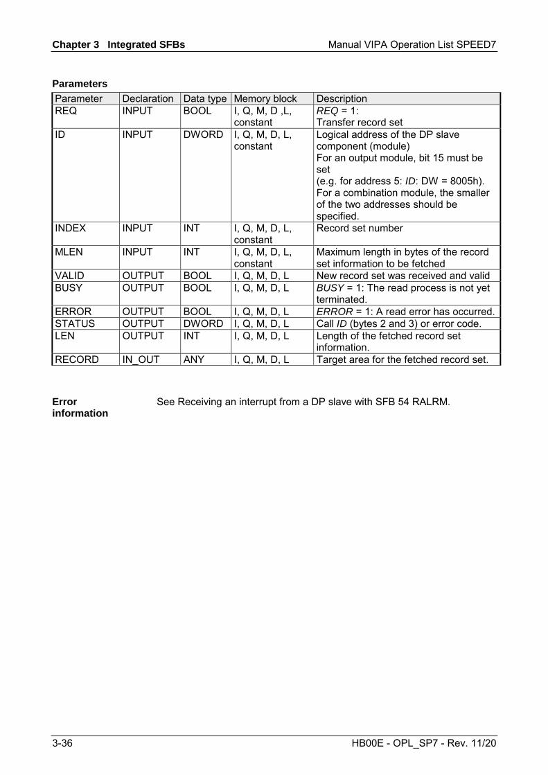
Chapter 3 Integrated SFBs Manual VIPA Operation List SPEED7
3-36 HB00E - OPL_SP7 - Rev. 11/20
Parameter Declaration Data type Memory block Description REQ INPUT BOOL I, Q, M, D ,L,
constant REQ = 1: Transfer record set
ID INPUT DWORD I, Q, M, D, L, constant
Logical address of the DP slave component (module) For an output module, bit 15 must be set (e.g. for address 5: ID: DW = 8005h). For a combination module, the smaller of the two addresses should be specified.
INDEX INPUT INT I, Q, M, D, L, constant
Record set number
MLEN INPUT INT I, Q, M, D, L, constant
Maximum length in bytes of the record set information to be fetched
VALID OUTPUT BOOL I, Q, M, D, L New record set was received and valid BUSY OUTPUT BOOL I, Q, M, D, L BUSY = 1: The read process is not yet
terminated. ERROR OUTPUT BOOL I, Q, M, D, L ERROR = 1: A read error has occurred.STATUS OUTPUT DWORD I, Q, M, D, L Call ID (bytes 2 and 3) or error code. LEN OUTPUT INT I, Q, M, D, L Length of the fetched record set
information. RECORD IN_OUT ANY I, Q, M, D, L Target area for the fetched record set.
See Receiving an interrupt from a DP slave with SFB 54 RALRM.
Parameters
Error information
Manual VIPA Operation List SPEED7 Chapter 3 Integrated SFBs
HB00E - OPL_SP7 - Rev. 11/20 3-37
SFB 53 - WRREC - Writing a Data Record in a DP-V1 slave
Note! The SFB 53 WRREC interface is identical to the FB WRREC defined in the standard "PROFIBUS Guideline PROFIBUS Communication and Proxy Function Blocks according to IEC 61131-3".
With the SFB 53 WRREC (Write record) you transfer a record set with the number INDEX to a DP slave component (module) that has been addressed via ID. Specify the byte length of the record set to be transmitted. The selected length of the source area RECORD should, therefore, have at least the length of LEN bytes. TRUE on output parameter DONE verifies that the record set has been successfully transferred to the DP slave. The output parameter ERROR indicates whether a record set transmission error has occurred. In this case, the output parameter STATUS contains the error information. System dependent this block cannot be interrupted!
Note! If a DP-V1 slave is configured using a GSD file (GSD stating with Rev. 3) and the DP interface of the DP master is set to Siemens "S7 compatible", than record sets must not be read from I/O modules in the user program with SFB 53. The reason is that in this case the DP master addresses the incorrect slot (configured slot +3). Remedy: Set the interface for DP master to "DP-V1"!
The SFB 53 WRREC operates asynchronously, that is, processing covers multiple SFB calls. Start the job by calling SFB 52 with REQ = 1. The job status is displayed via the output parameter BUSY and bytes 2 and 3 of output parameter STATUS. Here, the STATUS bytes 2 and 3 correspond with the output parameter RET_VAL of the asynchronously operating SFCs (see also meaning of REQ, RET_VAL and BUSY with Asynchronously Operating SFCs). Please note that you must assign the same value to the actual parameter of RECORD for all SFB 53 calls that belong to one and the same job. The same applies to the LEN parameters. Record set transmission is completed when the output parameter BUSY = FALSE.
Description
Operating principle

Chapter 3 Integrated SFBs Manual VIPA Operation List SPEED7
3-38 HB00E - OPL_SP7 - Rev. 11/20
Parameter Declaration Data type Memory block Description REQ INPUT BOOL I, Q, M, D, L,
constant REQ = 1: Transfer record set
ID INPUT DWORD I, Q, M, D, L, constant
Logical address of the DP slave component (module or submodule). For an output module, bit 15 must be set (e.g. for address 5: ID: DW = 8005h). For a combination module, the smaller of the two addresses should be specified.
INDEX INPUT INT I, Q, M, D, L, constant
Record set number.
LEN INPUT INT I, Q, M, D, L, constant
Maximum byte length of the record set to be transferred
DONE OUTPUT BOOL I, Q, M, D, L Record set was transferred BUSY OUTPUT BOOL I, Q, M, D, L BUSY = 1: The write process is not yet
terminated. ERROR OUTPUT BOOL I, Q, M, D, L ERROR = 1: A write error has occurred STATUS OUTPUT DWORD I, Q, M, D, L Call ID (bytes 2 and 3) or error code LEN OUTPUT INT I, Q, M, D, L Length of the fetched record set
information RECORD IN_OUT ANY I, Q, M, D, L Record set
See Receiving an interrupt from a DP slave with SFB 54 RALRM.
Parameters
Error information

Manual VIPA Operation List SPEED7 Chapter 3 Integrated SFBs
HB00E - OPL_SP7 - Rev. 11/20 3-39
SFB 54 - RALRM - Receiving an interrupt from a DP-V1 slave
Note! The SFB 54 RALRM interface is identical to the FB RALRM defined in the standard "PROFIBUS Guideline PROFIBUS Communication and Proxy Function Blocks according to IEC 61131-3".
The SFB 54 RALRM receives an interrupt with all corresponding information from a peripheral module (centralized structure) or from a DP slave component. It supplies this information to its output parameters. The information in the output parameters contains the start information of the called OB as well as information of the interrupt source. Call the SFB 54 only within the interrupt OB started by the CPU operating system as a result of the peripheral interrupt that is to be examined.
Note! If you call SFB 54 RALRM in an OB for which the start event was not triggered by peripherals, the SFB supplies correspondingly reduced information on its outputs. Make sure to use different instance DBs when you call SFB 54 in different OBs. If you want to evaluate data that are the result of an SFB 54 call outside of the associated interrupt OB you should moreover use a separate instance DP per OB start event.
Description

Chapter 3 Integrated SFBs Manual VIPA Operation List SPEED7
3-40 HB00E - OPL_SP7 - Rev. 11/20
Parameter Declaration Data type Memory block Description MODE INPUT INT I, Q, M, D, L,
constant Operating mode
F_ID INPUT DWORD I, Q, M, D, L, constant
Logical start address of the Component (module), from which interrupts are to be received.
MLEN INPUT INT I, Q, M, D, L, constant
Maximum length in bytes of the data interrupt information to be received
NEW OUTPUT BOOL I, Q, M, D, L A new interrupt was received. STATUS OUTPUT DWORD I, Q, M, D, L Error code of the SFB or DP master ID OUTPUT DWORD I, Q, M, D, L Logical start address of the component
(module), from which an interrupt was received. Bit 15 contains the I/O ID: 0: for an input address 1: for an output address
LEN OUTPUT INT I, Q, M, D, L Length of the received interrupt information
TINFO IN_OUT ANY I, Q, M, D, L (task information) Target range OB start and management information
AINFO IN_OUT ANY I, Q, M, D, L (interrupt information) Target area for header information and additional information. For AINFO you should provide a length of at least MLEN bytes.
You can call the SFB 54 in three operating modes (MODE): 0: shows the component that triggered the interrupt in the output parameter ID and sets the output parameter NEW to TRUE. 1: describes all output parameters, independent on the interrupt-triggering component. 2: checks whether the component specified in input parameter F_ID has triggered the interrupt. - if not, NEW = FALSE - if yes, NEW = TRUE, and all other outputs parameters are described.
Note! If you select a target area TINFO or AINFO that is too short the SFC 54 cannot enter the full information.
Parameters
MODE

Manual VIPA Operation List SPEED7 Chapter 3 Integrated SFBs
HB00E - OPL_SP7 - Rev. 11/20 3-41
Data structure of the target area (task information):
Byte Data type Description 0 ... 19 Start information of the OB in which SFC 54 was currently called:
Byte 0 ... 11: structured like the parameter TOP_SI in SFC 6 RD_SINFO Byte 12 ... 19: date and time the OB was requested
20 ... 27 Management information: 20 Byte centralized: 0
decentralized: DP master system ID (possible values: 1 ... 255) 21 Byte central: Module rack number (possible values: 0 ... 31)
distributed: Number of DP station (possible values: 0 ... 127) centralized: 0
0000: DP 0001: DPS7 0010: DPS7 V1 0011: DP-V1
Bit 3 ... 0 slave type
as of 0100: reserved 0000: DP
22 Byte decentralized:
Bit 7 ... 4 Profile type as of 0001: reserved
centralized: 0
0000: Transparent (Interrupt originates from a configured decentralized module)
0001: Representative (Interrupt originating from a non-DP-V1 slave or a slot that is not configured)
0010: Generated interrupt (generated in the CPU)
Bit 3 ... 0 Interrupt info type
as of 0011: reserved 0000: Initial
23 Byte
decentralized:
Bit 7 ... 4 Structure version as of 0001: reserved
continued ...
TINFO

Chapter 3 Integrated SFBs Manual VIPA Operation List SPEED7
3-42 HB00E - OPL_SP7 - Rev. 11/20
... continue TINFO Byte Data type Description
centralized: 0 decentralized: Flags of the DP master interface Bit 0 = 0: Interrupt originating from an
integrated DP interface Bit 0 = 1: Interrupt originating from an
external DP interface
24 Byte
Bit 7 ... 1: reserved centralized: 0 decentralized: Flags of the DP slave interface Bit 0: EXT_DIAG_Bit of the diagnostic
message frame, or 0 if this bit does not exist in the interrupt
25 Byte
Bit 7 ... 1: reserved centralized: 0 26, 27 WORD decentralized: PROFIBUS ID number
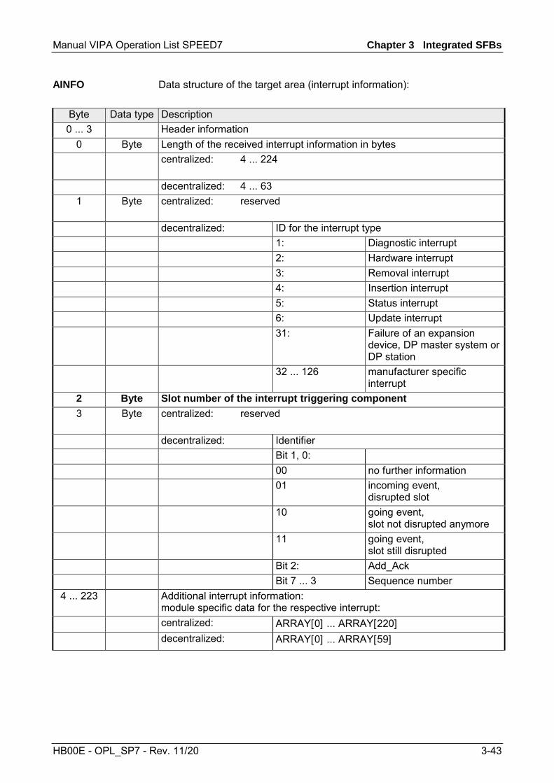
Manual VIPA Operation List SPEED7 Chapter 3 Integrated SFBs
HB00E - OPL_SP7 - Rev. 11/20 3-43
Data structure of the target area (interrupt information):
Byte Data type Description 0 ... 3 Header information
0 Byte Length of the received interrupt information in bytes centralized: 4 ... 224
decentralized: 4 ... 63
1 Byte centralized: reserved
decentralized: ID for the interrupt type 1: Diagnostic interrupt 2: Hardware interrupt 3: Removal interrupt 4: Insertion interrupt 5: Status interrupt 6: Update interrupt 31: Failure of an expansion
device, DP master system or DP station
32 ... 126 manufacturer specific interrupt
2 Byte Slot number of the interrupt triggering component 3 Byte centralized: reserved
decentralized: Identifier Bit 1, 0: 00 no further information 01 incoming event,
disrupted slot 10 going event,
slot not disrupted anymore 11 going event,
slot still disrupted Bit 2: Add_Ack Bit 7 ... 3 Sequence number
4 ... 223 Additional interrupt information: module specific data for the respective interrupt:
centralized: ARRAY[0] ... ARRAY[220] decentralized: ARRAY[0] ... ARRAY[59]
AINFO
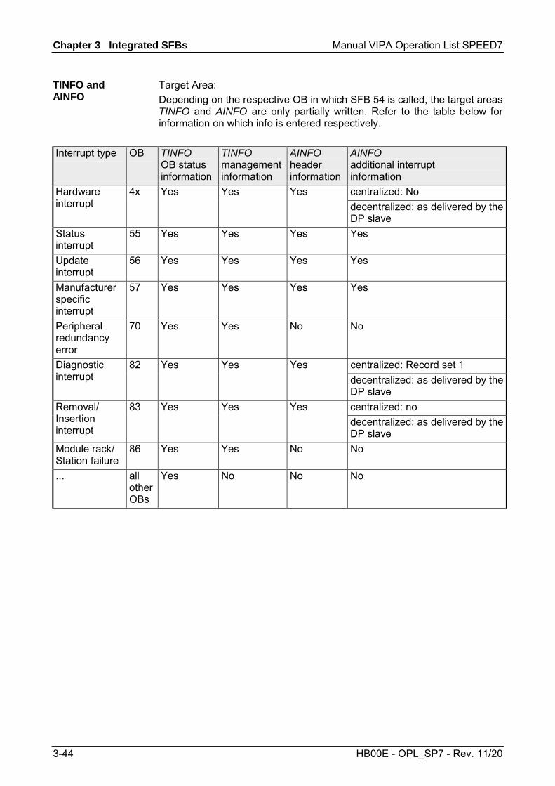
Chapter 3 Integrated SFBs Manual VIPA Operation List SPEED7
3-44 HB00E - OPL_SP7 - Rev. 11/20
Target Area: Depending on the respective OB in which SFB 54 is called, the target areas TINFO and AINFO are only partially written. Refer to the table below for information on which info is entered respectively.
Interrupt type OB TINFO OB status information
TINFO management information
AINFO header information
AINFO additional interrupt information
4x Yes Yes Yes centralized: No Hardware interrupt decentralized: as delivered by the
DP slave Status interrupt
55 Yes Yes Yes Yes
Update interrupt
56 Yes Yes Yes Yes
Manufacturer specific interrupt
57 Yes Yes Yes Yes
Peripheral redundancy error
70 Yes Yes No No
82 Yes Yes Yes centralized: Record set 1 Diagnostic interrupt decentralized: as delivered by the
DP slave 83 Yes Yes Yes centralized: no Removal/
Insertion interrupt
decentralized: as delivered by the DP slave
Module rack/ Station failure
86 Yes Yes No No
... all other OBs
Yes No No No
TINFO and AINFO

Manual VIPA Operation List SPEED7 Chapter 3 Integrated SFBs
HB00E - OPL_SP7 - Rev. 11/20 3-45
The output parameter STATUS contains information. It is interpreted as ARRAY[1...4] OF BYTE the error information has the following structure:
Field element Name Description STATUS[1] Function_Num 00h: if no error
Function ID from DP-V1-PDU: in error case 80h is OR linked. If no DP-V1 protocol element is used: C0h
STATUS[2] Error_Decode Location of the error ID STATUS[3] Error_1 Error ID STATUS[4] Error_2 Manufacturer specific error ID expansion:
With DP-V1 errors, the DP master passes on STATUS[4] to the CPU and to the SFB. Without DP-V1 error, this value is set to 0, with the following exceptions for the SFB 52: • STATUS[4] contains the target area length from
RECORD, if MLEN > the target area length from RECORD
• STATUS[4]=MLEN, if the actual record set length < MLEN < the target area length from RECORD
STATUS[2] (Location of the error ID) can have the following values: Error_Decode Source Description 00 ... 7Fh CPU No error no warning 80h DP-V1 Error according to IEC 61158-6 81h ... 8Fh CPU 8xh shows an error in the nth call parameter of the SFB. FEh, FFh DP Profile Profile-specific error
Error information

Chapter 3 Integrated SFBs Manual VIPA Operation List SPEED7
3-46 HB00E - OPL_SP7 - Rev. 11/20
STATUS[3] (Error ID) can have the following values: Error_Decode Error_Code_1 Explanation
according to DP-V1 Description
00h 00h no error, no warning 00h reserved, reject Initial call;
no active record set transfer 01h reserved, reject Initial call;
record set transfer has started
70h
02h reserved, reject Intermediate call; record set transfer already active
90h reserved, pass Invalid logical start address 92h reserved, pass Illegal Type for ANY Pointer 93h reserved, pass The DP component addressed via ID
or F_ID is not configured. A0h read error Negative acknowledgement while
reading the module. A1h write error Negative acknowledgement while
writing the module. A2h module failure at layer 2 A3h reserved, pass DP protocol error with
Direct-Data-Link-Mapper or User-Interface/User
A4h reserved, pass Bus communication disrupted A5h reserved, pass - A7h reserved, pass DP slave or module is occupied
(temporary error) A8h version conflict DP slave or module reports non-
compatible versions A9h feature not supported Feature not supported by DP slave
or module AA ... AFh user specific DP slave or module reports a
manufacturer specific error in its application. Please check the documentation from the manufacturer of the DP slave or module.
B0h invalid index Record set not known in module illegal record set number ≥256.
B1h write length error Wrong length specified in parameter RECORD; with SFB 54: length error in AINFO.
B2h invalid slot Configured slot not occupied. B3h type conflict Actual module type not equal to
specified module type B4h invalid area DP slave or module reports access
to an invalid area B5h state conflict DP slave or module not ready B6h access denied DP slave or module denies access
80h
continued ...

Manual VIPA Operation List SPEED7 Chapter 3 Integrated SFBs
HB00E - OPL_SP7 - Rev. 11/20 3-47
... continue STATUS[3] Error_Decode Error_Code_1 Explanation
according to DP-V1 Description
80h B7h invalid range DP slave or module reports an invalid range for a parameter or value
B8h invalid parameter DP slave or module reports an invalid parameter
B9h invalid type DP slave or module reports an invalid type
BAh ... BFh user specific DP slave or module reports a manufacturer specific error when accessing. Please check the documentation from the manufacturer of the DP slave or module.
C0h read constrain conflict The module has the record set, however, there are no read data yet.
C1h write constrain conflict The data of the previous write request to the module for the same record set have not yet been processed by the module.
C2h resource busy The module currently processes the maximum possible jobs for a CPU.
C3h resource unavailable The required operating resources are currently occupied.
C4h Internal temporary error. Job could not be carried out. Repeat the job. If this error occurs often, check your plant for sources of electrical interference.
C5h DP slave or module not available C6h Record set transfer was canceled
due to priority class cancellation C7h Job canceled due to restart of
DP masters C8h ... CFh DP slave or module reports a
manufacturer specific resource error. Please check the documentation from the manufacturer of the DP slave or module.
Dxh user specific DP slave specific, Refer to the description of the DP slaves.
00h ... FFh Error in the initial call parameter (with SFB 54: MODE)
81h
00h Illegal operating mode continued ...

Chapter 3 Integrated SFBs Manual VIPA Operation List SPEED7
3-48 HB00E - OPL_SP7 - Rev. 11/20
... continue STATUS[3] Error_Decode Error_Code_1 Explanation
according to DP-V1 Description
82h 00h ... FFh Error in the 2. call parameter. ... ... ...
00h ... FFh Error in the 8. call parameter (with SFB 54: TINFO)
01h Wrong syntax ID 23h Quantity frame exceeded or target
area too small 24h Wrong range ID 32h DB/DI no. out of user range
88h
3Ah DB/DI no. is NULL for area ID DB/DI or specified DB/DI does not exist.
00h ... FFh Error in the 9. call parameter (with SFB 54: AINFO)
01h Wrong syntax ID 23h Quantity frame exceeded or target
area too small 24h Wrong range ID 32h DB/DI no. out of user range
89h
3Ah DB/DI no. is NULL for area ID DB/DI or specified DB/DI does not exist
8Ah 00h ... FFh Error in the 10. call parameter ... ... ... 8Fh 00h ... FFh Error in the 15. call parameter FEh, FFh Profile-specific error
Manual VIPA Operation List SPEED7 Chapter 4 Integrated Standard FBs
HB00E - OPL_SP7 - Rev. 11/20 4-1
Chapter 4 Integrated Standard FBs
Here the description of the integrated standard FBs of the SPEED7 CPUs from VIPA may be found. The description of the FBs of the VIPA library may be found at the chapter "VIPA specific blocks".
Topic Page Chapter 4 Integrated Standard FBs ................................................ 4-1
Overview Integrated Standard-FBs ...................................................... 4-2 Open Communication - FB 63 ... FB 68................................................ 4-3 UDT 65 - TCON_PAR .......................................................................... 4-5 UDT 66 - TCON_ADR.......................................................................... 4-9 Parameterization - Example ............................................................... 4-10 FB 63 - TSEND - Sending data - TCP native and ISO on TCP........... 4-12 FB 64 - TRCV - Receiving Data - TCP native and ISO on TCP.......... 4-15 FB 65 - TCON - Establishing a connection......................................... 4-19 FB 66 - TDISCON - Terminating a connection ................................... 4-22 FB 67 - TUSEND - Sending data - UDP............................................. 4-24 FB 68 - TURCV - Receiving data - UDP............................................ 4-27
Overview
Content
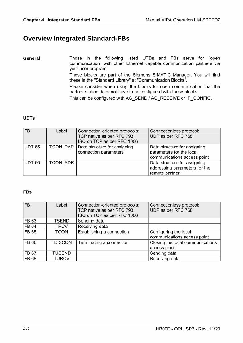
Chapter 4 Integrated Standard FBs Manual VIPA Operation List SPEED7
4-2 HB00E - OPL_SP7 - Rev. 11/20
Overview Integrated Standard-FBs
Those in the following listed UTDs and FBs serve for "open communication" with other Ethernet capable communication partners via your user program. These blocks are part of the Siemens SIMATIC Manager. You will find these in the "Standard Library" at "Communication Blocks". Please consider when using the blocks for open communication that the partner station does not have to be configured with these blocks. This can be configured with AG_SEND / AG_RECEIVE or IP_CONFIG.
FB Label Connection-oriented protocols: TCP native as per RFC 793, ISO on TCP as per RFC 1006
Connectionless protocol: UDP as per RFC 768
UDT 65 TCON_PAR Data structure for assigning connection parameters
Data structure for assigning parameters for the local communications access point
UDT 66 TCON_ADR Data structure for assigning addressing parameters for the remote partner
FB Label Connection-oriented protocols: TCP native as per RFC 793, ISO on TCP as per RFC 1006
Connectionless protocol: UDP as per RFC 768
FB 63 TSEND Sending data FB 64 TRCV Receiving data FB 65 TCON Establishing a connection Configuring the local
communications access point FB 66 TDISCON Terminating a connection Closing the local communications
access point FB 67 TUSEND Sending data FB 68 TURCV Receiving data
General
UDTs
FBs

Manual VIPA Operation List SPEED7 Chapter 4 Integrated Standard FBs
HB00E - OPL_SP7 - Rev. 11/20 4-3
Open Communication - FB 63 ... FB 68
Connection-oriented protocols establish a (logical) connection to the communication partner before data transmission is started. And if necessary they terminate the connection after the data transfer was finished. Connection-oriented protocols are used for data transmission when reliable, guaranteed delivery is of particular importance. In general, many logical connections can exist on one physical line. The following connection-oriented protocols are supported with FBs for open communication via Industrial Ethernet: • TCP/IP native as per RFC 793 (with connection types 01h and 11h) • ISO on TCP as per RFC 1006 (with connection type 12h)
During data transmission, no information about the length or about the start and end of a message is transmitted. However, the receiver has no means of detecting where one message ends in the data stream and the next one begins. The transfer is stream-oriented. For this reason, it is recommended that the data length of the FBs is identical for the sending and receiving station. If the number of received data does not fit to the preset length you either will get not the whole data, or you will get data of the following job. The receive block copies as many bytes into the receive area as you have specified as length. After this, it will set NDR to TRUE and write RCVD_LEN with the value of LEN. With each additional call, you will thus receive another block of sent data.
During data transmission, information on the length and the end of the message is also transmitted. If you have specified the length of the data to be received greater than the length of the data to be sent, the receive block will copy the received data completely into the receive range. After this, it will set NDR to TRUE and write RCVD_LEN with the length of the sent data. If you have specified the length of the data to be received less than the length of the sent data, the receive block will not copy any data into the receive range but instead will supply the following error information: ERROR = 1, STATUS = 8088h.
Connection-oriented protocols
TCP native
ISO on TCP

Chapter 4 Integrated Standard FBs Manual VIPA Operation List SPEED7
4-4 HB00E - OPL_SP7 - Rev. 11/20
There is thus no establishment and termination of a connection with a remote partner. Connection-less protocols transmit data with no acknowledge and with no reliable guaranteed delivery to the remote partner. The following connection-oriented protocol is supported with FBs for open communication via Industrial Ethernet: • UDP according to RFC 768 (with connection type 13h)
In this case, when calling the sending block you have to specify the address parameters of the receiver (IP address and port number). During data transmission, information on the length and the end of the message is also transmitted. In order to be able to use the sending and receiving blocks first you have to configure the local communications access point at both sides. With each new call of the sending block, you re-reference the remote partner by specifying its IP address and its port number. If you have specified the length of the data to be received greater than the length of the data to be sent, the receive block will copy the received data completely into the receive range. After this, it will set NDR to TRUE and write RCVD_LEN with the length of the sent data. If you have specified the length of the data to be received less than the length of the sent data, the receive block will not copy any data into the receive range but instead will supply the following error information: ERROR = 1, STATUS = 8088h.
Connection-less protocol
UDP

Manual VIPA Operation List SPEED7 Chapter 4 Integrated Standard FBs
HB00E - OPL_SP7 - Rev. 11/20 4-5
UDT 65 - TCON_PAR
In the TCP Connection parameterization of native or ISO on TCP, you define which communication partners enabled the connection and which to a request through the communication partner performs a passive connection. If both communication partners have launched their connection, the operating system can restore the communication link. To communicate a DB is needed. Facility whereby the DB's data structure from the UDT 65 TCON_PAR. For each connection such a data structure is needed that can be summarized in a global DB. The CONNECT connection parameter address of FB 65 TCON contains a reference to the associated connection description (e.g. P#DB10.DBX0.0 byte 64).
Byte Parameter Data type Start value Description 0 ... 1 block_length WORD 40h Length of UDT 65: 64 Bytes (fixed) 2 ... 3 id WORD 0000h Reference to the connection
(range of values: 0001h ... 0FFFh) You must specify the value of the parameter in the respective block with the ID.
4 connection _type BYTE 01h Connection type: • 11h: TCP/IP native • 12h: ISO on TCP • 01h: TCP/IP native (Compatibility mode)
5 active_est BOOL FALSE ID for the way the connection is established: • FALSE: passive establishment • TRUE: active establishment
6 local_device_id BYTE 02h • 02h: communication via CP of the VIPA-CPU 02h (fix)
7 local_tsap_id_len BYTE 02h Length of parameter local_tsap_id used; possible values: • 0 or 2, if connection type = 01h or 11h
For the active side, only the value 00h is permitted.
• 2 to 16, if connection type = 12h 8 rem_subnet_id_le
n BYTE 00h This parameter is currently not used. You must
assign 00h to it. 9 rem_staddr_len BYTE 00h Length of address for the remote connection
transmission point: • 0: unspecified, i.e. parameter rem_staddr is
irrelevant. 4: valid IP address in the parameter rem_staddr
continue ...
Data structure for assigning connection
Data structure
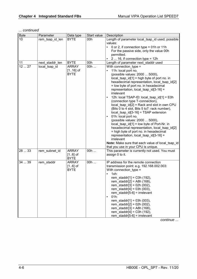
Chapter 4 Integrated Standard FBs Manual VIPA Operation List SPEED7
4-6 HB00E - OPL_SP7 - Rev. 11/20
... continued Byte Parameter Data type Start value Description 10 rem_tsap_id_len BYTE 00h Length of parameter local_tsap_id used; possible
values: • 0 or 2, if connection type = 01h or 11h
For the passive side, only the value 00h permitted.
• 2 ... 16, if connection type = 12h 11 next_staddr_len BYTE 00h Length of parameter next_staddr used 12 ... 27 local_tsap_id ARRAY
[1..16] of BYTE
00h ... With connection_type = • 11h: local port no.
(possible values: 2000 ... 5000), local_tsap_id[1] = high byte of port no. in hexadecimal representation, local_tsap_id[2] = low byte of port no. in hexadecimal representation, local_tsap_id[3-16] = irrelevant
• 12h: local TSAP-ID: local_tsap_id[1] = E0h (connection type T-connection), local_tsap_id[2] = Rack and slot in own CPU (Bits 0 to 4 slot, Bits 5 to7: rack number), local_tsap_id[3-16] = TSAP extension
• 01h: local port no. (possible values: 2000 ... 5000), local_tsap_id[1] = low byte of Port-Nr. in hexadecimal representation, local_tsap_id[2] = high byte of port no. in hexadecimal representation, local_tsap_id[3-16] = irrelevant
Note: Make sure that each value of local_tsap_id that you use in your CPU is unique.
28 ... 33 rem_subnet_id ARRAY [1..6] of BYTE
00h ... This parameter is currently not used. You must assign 0 to it.
34 ... 39 rem_staddr ARRAY [1..6] of BYTE
00h ... IP address for the remote connection transmission point: e.g. 192.168.002.003: With connection_type = • 1xh:
rem_staddr[1] = C0h (192), rem_staddr[2] = A8h (168), rem_staddr[3] = 02h (002), rem_staddr[4] = 03h (003), rem_staddr[5-6] = irrelevant
• 01h: rem_staddr[1] = 03h (003), rem_staddr[2] = 02h (002), rem_staddr[3] = A8h (168), rem_staddr[4] = C0h (192), rem_staddr[5-6] = irrelevant
continue ...

Manual VIPA Operation List SPEED7 Chapter 4 Integrated Standard FBs
HB00E - OPL_SP7 - Rev. 11/20 4-7
... continued Byte Parameter Data type Start value Description 40 ... 55 rem_tsap_id ARRAY
[1..16] of BYTE
00h ... With connection_type = • 11h: remote port no.
(possible values: 2000 ... 5000), rem_tsap_id[1] = high byte of port no in hexadecimal representation, rem_tsap_id[2] = low byte of port no in hexadecimal representation, rem_tsap_id[3-16] = irrelevant
• 12h: remote TSAP-ID: rem_tsap_id[1] = E0h (connection type T-connection), rem_tsap_id[2] = Rack and slot for the remote connection transmission point (CPU) (bits 0 to 4: slot, bits 5 ... 7: rack number), rem_tsap_id[3-16] = TSAP extension
• 01h: remote port no. (possible values: 2000 ... 5000), local_tsap_id[1] = low byte of port no. in hexadecimal representation, local_tsap_id[2] = high byte of port no. in hexadecimal representation, local_tsap_id[3-16] = irrelevant
56 ... 61 next_staddr ARRAY [1..6] of BYTE
00h ... At local_device_id = • 00h:
next_staddr[1]: Rack and slot of associated (local) CP (bits 0 ... 4: slot, bits 5 ... 7: rack number) next_staddr[2-6]: irrelevant
• 02h: next_staddr[1-6]: irrelevant 62 ... 63 spare WORD 0000h irrelevant
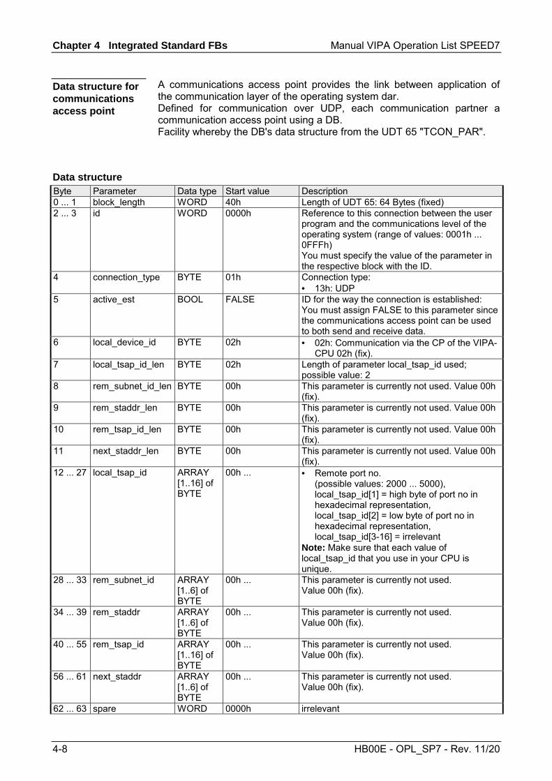
Chapter 4 Integrated Standard FBs Manual VIPA Operation List SPEED7
4-8 HB00E - OPL_SP7 - Rev. 11/20
A communications access point provides the link between application of the communication layer of the operating system dar. Defined for communication over UDP, each communication partner a communication access point using a DB. Facility whereby the DB's data structure from the UDT 65 "TCON_PAR".
Byte Parameter Data type Start value Description 0 ... 1 block_length WORD 40h Length of UDT 65: 64 Bytes (fixed) 2 ... 3 id WORD 0000h Reference to this connection between the user
program and the communications level of the operating system (range of values: 0001h ... 0FFFh) You must specify the value of the parameter in the respective block with the ID.
4 connection_type BYTE 01h Connection type: • 13h: UDP
5 active_est BOOL FALSE ID for the way the connection is established: You must assign FALSE to this parameter since the communications access point can be used to both send and receive data.
6 local_device_id BYTE 02h • 02h: Communication via the CP of the VIPA-CPU 02h (fix).
7 local_tsap_id_len BYTE 02h Length of parameter local_tsap_id used; possible value: 2
8 rem_subnet_id_len BYTE 00h This parameter is currently not used. Value 00h (fix).
9 rem_staddr_len BYTE 00h This parameter is currently not used. Value 00h (fix).
10 rem_tsap_id_len BYTE 00h This parameter is currently not used. Value 00h (fix).
11 next_staddr_len BYTE 00h This parameter is currently not used. Value 00h (fix).
12 ... 27 local_tsap_id ARRAY [1..16] of BYTE
00h ... • Remote port no. (possible values: 2000 ... 5000), local_tsap_id[1] = high byte of port no in hexadecimal representation, local_tsap_id[2] = low byte of port no in hexadecimal representation, local_tsap_id[3-16] = irrelevant
Note: Make sure that each value of local_tsap_id that you use in your CPU is unique.
28 ... 33 rem_subnet_id ARRAY [1..6] of BYTE
00h ... This parameter is currently not used. Value 00h (fix).
34 ... 39 rem_staddr ARRAY [1..6] of BYTE
00h ... This parameter is currently not used. Value 00h (fix).
40 ... 55 rem_tsap_id ARRAY [1..16] of BYTE
00h ... This parameter is currently not used. Value 00h (fix).
56 ... 61 next_staddr ARRAY [1..6] of BYTE
00h ... This parameter is currently not used. Value 00h (fix).
62 ... 63 spare WORD 0000h irrelevant
Data structure for communications access point
Data structure

Manual VIPA Operation List SPEED7 Chapter 4 Integrated Standard FBs
HB00E - OPL_SP7 - Rev. 11/20 4-9
UDT 66 - TCON_ADR
With FB 67 TUSEND, at the parameter ADDR you transfer the address of the receiver. This address information must have structure specified below. With FB 68 TURCV, in the parameter ADDR you get the address of the sender of the data that were received. This address information must have structure specified below.
You have to create an DB that contains one or more data structures as per UDT 66 TADDR_PAR. In parameter ADDR of FB 67 TUSEND you transfer and in parameter ADDR of FB 68 TURCV you receive a pointer to the address of the associated remote partner (e.g. P#DB10.DBX0.0 byte 8).
Byte Parameter Data type Start value Description 0 ... 3 rem_ip_addr ARRAY
[1..4] of BYTE
00h ... IP address of the remote partner, e.g. 192.168.002.003: • rem_ip_addr[1] = C0h (192) • rem_ip_addr[2] = A8h (168) • rem_ip_addr[3] = 02h (002) • rem_ip_addr[4] = 03h (003)
4 ... 5 rem_port_nr ARRAY [1..2] of BYTE
00h ... remote port no. (possible values: 2000 ... 5000) • rem_port_nr[1] = high byte of port no. in
hexadecimal representation • rem_port_nr[2] = low byte of port no. in
hexadecimal representation 6 ... 7 spare ARRAY
[1..2] of BYTE
00h ... irrelevant
Description
Data block
Structure of the address information for the remote partner

Chapter 4 Integrated Standard FBs Manual VIPA Operation List SPEED7
4-10 HB00E - OPL_SP7 - Rev. 11/20
Parameterization - Example
Below it is shown by an example how the parameter DB for a communication link is to be set up for transmitter and receiver. The communication partner are 2 CPU 317-4NE12 from VIPA. Here the communication takes place via the integrated CP 343 of each. The connection type is TCP/IP native.
Properties Station A CPU 317-4NE12
Station B CPU 317-4NE12
Connection active passive IP address 192.168.3.125 192.168.3.142 Physical address CPU Rack 0, slot 2 Rack 0, slot 4 Physical address PG/OP Rack 0, slot 4 Rack 0, slot 4 Physical address of the CP Rack 0, slot 5 Rack 0, slot 5 Local port no. not relevant 2005
The table shows the parameter DB for an active connection establishment.
Parameter Data type Value in the example Description block_length WORD 40h DB block length id WORD 0001h Reference to this connection connection_type BYTE 11h Connection type: TCP/IP native active_est BOOL TRUE Active connection establishment local_device_id BYTE 02h Communication via the integrated
Ethernet interface local_tsap_id_len BYTE 00h
(only this value is possible) Parameter local_tsap_id is not used
rem_staddr_len BYTE 04h Length of address for the remote connection transmission point: • 4: valid IP address in parameter
rem_staddr rem_tsap_id_len BYTE 02h
(only this value is possible) Length of parameter rem_tsap_id used
rem_staddr ARRAY [1..6] of BYTE
"192.168.3.125" • rem_staddr[1] = C0h (192) • rem_staddr[2] = A8h (168) • rem_staddr[3] = 03h (3) • rem_staddr[4] = 7Dh (125) • rem_staddr[5-6] = not relevant
IP address of the remote connection transmission point
rem_tsap_id ARRAY [1..16] of BYTE
"2005" • rem_tsap_id[1] = 07h • rem_tsap_id[2] = D5h • rem_tsap_id[3-16] = not relevant
Remote port no.: 2005 = 07D5h
Overview
Data of the communication partners
Parameter DB Station A
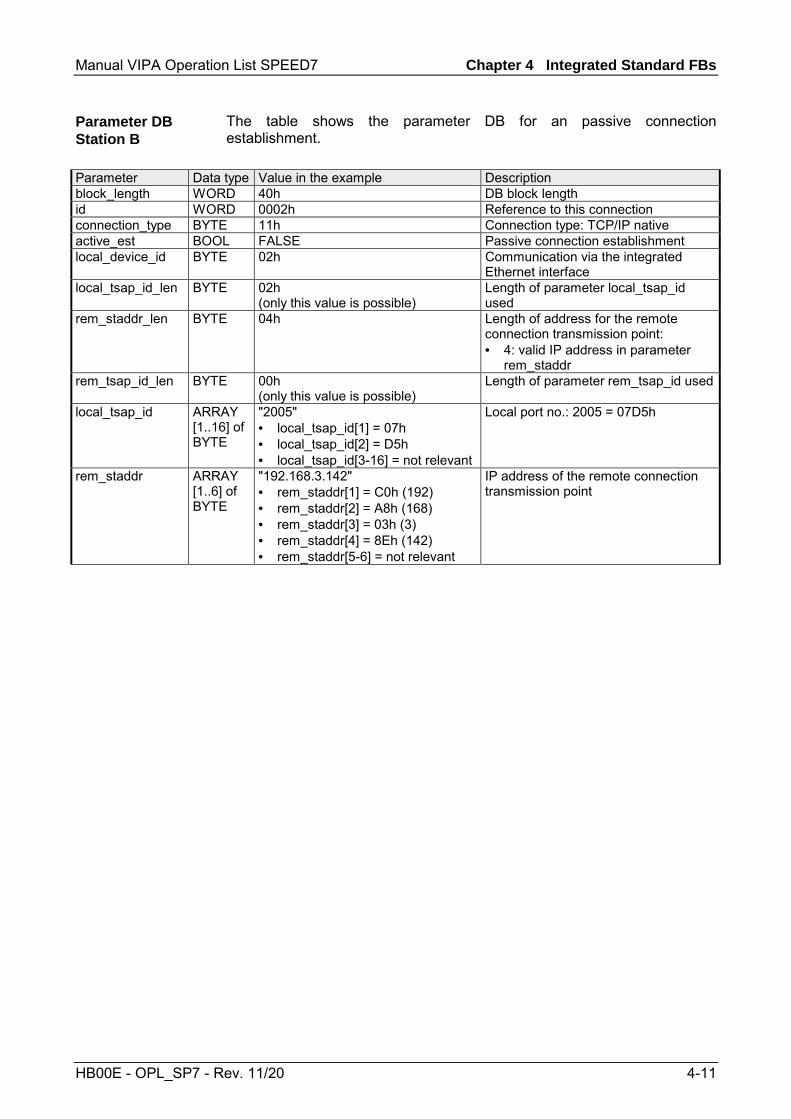
Manual VIPA Operation List SPEED7 Chapter 4 Integrated Standard FBs
HB00E - OPL_SP7 - Rev. 11/20 4-11
The table shows the parameter DB for an passive connection establishment.
Parameter Data type Value in the example Description block_length WORD 40h DB block length id WORD 0002h Reference to this connection connection_type BYTE 11h Connection type: TCP/IP native active_est BOOL FALSE Passive connection establishment local_device_id BYTE 02h Communication via the integrated
Ethernet interface local_tsap_id_len BYTE 02h
(only this value is possible) Length of parameter local_tsap_id used
rem_staddr_len BYTE 04h Length of address for the remote connection transmission point: • 4: valid IP address in parameter
rem_staddr rem_tsap_id_len BYTE 00h
(only this value is possible) Length of parameter rem_tsap_id used
local_tsap_id ARRAY [1..16] of BYTE
"2005" • local_tsap_id[1] = 07h • local_tsap_id[2] = D5h • local_tsap_id[3-16] = not relevant
Local port no.: 2005 = 07D5h
rem_staddr ARRAY [1..6] of BYTE
"192.168.3.142" • rem_staddr[1] = C0h (192) • rem_staddr[2] = A8h (168) • rem_staddr[3] = 03h (3) • rem_staddr[4] = 8Eh (142) • rem_staddr[5-6] = not relevant
IP address of the remote connection transmission point
Parameter DB Station B
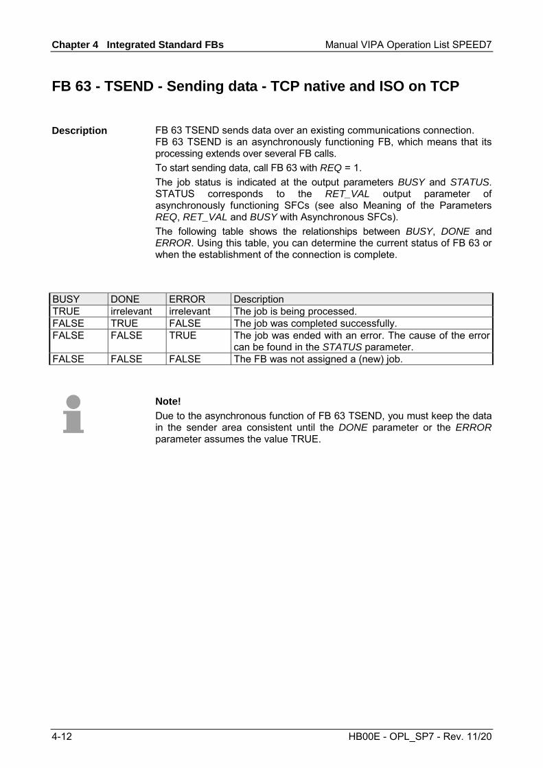
Chapter 4 Integrated Standard FBs Manual VIPA Operation List SPEED7
4-12 HB00E - OPL_SP7 - Rev. 11/20
FB 63 - TSEND - Sending data - TCP native and ISO on TCP
FB 63 TSEND sends data over an existing communications connection. FB 63 TSEND is an asynchronously functioning FB, which means that its processing extends over several FB calls. To start sending data, call FB 63 with REQ = 1. The job status is indicated at the output parameters BUSY and STATUS. STATUS corresponds to the RET_VAL output parameter of asynchronously functioning SFCs (see also Meaning of the Parameters REQ, RET_VAL and BUSY with Asynchronous SFCs). The following table shows the relationships between BUSY, DONE and ERROR. Using this table, you can determine the current status of FB 63 or when the establishment of the connection is complete.
BUSY DONE ERROR Description TRUE irrelevant irrelevant The job is being processed. FALSE TRUE FALSE The job was completed successfully. FALSE FALSE TRUE The job was ended with an error. The cause of the error
can be found in the STATUS parameter. FALSE FALSE FALSE The FB was not assigned a (new) job.
Note! Due to the asynchronous function of FB 63 TSEND, you must keep the data in the sender area consistent until the DONE parameter or the ERROR parameter assumes the value TRUE.
Description

Manual VIPA Operation List SPEED7 Chapter 4 Integrated Standard FBs
HB00E - OPL_SP7 - Rev. 11/20 4-13
Parameter Declaration Data type Memory area Description REQ INPUT BOOL E, A, M, D, L Control parameter REQUEST, initiates
the transmission at rising edge. At the first call with REQ = 1, data are transmitted from the area specified by the DATA parameter.
ID INPUT WORD M, D, constant Reference to the connection to be terminated. ID must be identical to the associated parameter ID in the local connection description. Range of values: 0001h ... 0FFFh
LEN INPUT INT E, A, M, D, L Number of bytes to be sent with the job Range of values:
• 1 ... 1460, if connection type = 01h • 1 ... 8192, if connection type = 11h • 1 ... 1452, if connection type = 12h
and a CP is being used • 1 ... 8192, if connection type = 12h
and no CP is being used DONE OUTPUT BOOL E, A, M, D, L DONE status parameter:
• 0: Job not yet started or still running. • 1: Job executed without error.
BUSY OUTPUT BOOL E, A, M, D, L • BUSY = 1: Job is not yet completed. A new job cannot be triggered.
• BUSY = 0: Job is completed. ERROR OUTPUT BOOL E, A, M, D, L ERROR status parameter:
• ERROR = 1: Error occurred during processing. STATUS provides detailed information on the type of error.
STATUS OUTPUT WORD M, D STATUS status parameter: Error information
DATA IN_OUT ANY E, A, M, D Send area, contains address and length. The address refers to: • The process image input • The process image output • A bit memory • A data block
Parameters

Chapter 4 Integrated Standard FBs Manual VIPA Operation List SPEED7
4-14 HB00E - OPL_SP7 - Rev. 11/20
ERROR STATUS Description
0 0000h Send job completed without error. 0 7000h First call with REQ = 0, sending not initiated. 0 7001h First call with REQ = 1, sending initiated. 0 7002h Follow-on call (REQ irrelevant ), job being processed
Note: during this processing the operating system accesses the data in the DATA send buffer.
1 8085h LEN parameter has the value 0 or is greater than the largest permitted value.
1 8086h The ID parameter is not in the permitted address range. 0 8088h LEN parameter is larger than the memory area specified in DATA. 1 80A1h Communications error:
• FB 65 TCON was not yet called for the specified ID • The specified connection is currently being terminated.
Transmission over this connection is not possible. • The interface is being reinitialized.
1 80B3h The parameter for the connection type (connection_type parameter in the connection description) is set to UDP. Please use the FB 67 TUSEND.
1 80C3h The operating resources (memory) in the CPU are temporarily occupied.
1 80C4h Temporary communications error: • The connection to the communications partner cannot be
established at this time. • The interface is receiving new parameters.
1 8822h DATA parameter: Source area invalid: area does not exist in DB. 1 8824h DATA parameter: Range error in ANY pointer. 1 8832h DATA parameter: DB number too large. 1 883Ah DATA parameter: Access to send buffer not possible
(e.g. due to deleted DB). 1 887Fh DATA parameter: Internal error, such as an invalid ANY reference.
Error information

Manual VIPA Operation List SPEED7 Chapter 4 Integrated Standard FBs
HB00E - OPL_SP7 - Rev. 11/20 4-15
FB 64 - TRCV - Receiving Data - TCP native and ISO on TCP
FB 64 TRCV receives data over an existing communication connection. The are two variants available for receiving and processing the data: • Variant 1: Received data block is processed immediately. • Variant 2: Received data block is stored in a receive buffer and is only
processed when the buffer is full. The following table shows the relationships between the connection type is shown in the following table: Connection type Variant 01h and 11h The user can specify the variant. 12h Variant 2 (fix)
The following table describes both variants in detail.
Received Data ...
Range Values for LEN
Range Values for RCVD_LEN
Description
are available immediately
0 1 ... x The data go into a buffer whose length x is specified in the ANY pointer of the receive buffer (DATA parameter). After being received, a data block is immediately available in the receive buffer. The amount of data received (RCVD_LEN parameter) can be no greater than the size specified in the DATA parameter. Receiving is indicated by NDR = 1.
are stored in the receive buffer. The data are available as soon as the configured length is reached.
• 1 ... 1460, if the connection type= 01h
• 1 ... 8192, if the connection type = 11h
• 1 ... 1452, if the connection type = 12h and a CP is being used
• 1 ... 8192, if the connection type = 12h and no CP is being used
Same value as in the LEN parameter
The data go into a buffer whose length is specified by the LEN parameter. If this specified length is reached, the received data are made available in the DATA parameter (NDR = 1).
Description

Chapter 4 Integrated Standard FBs Manual VIPA Operation List SPEED7
4-16 HB00E - OPL_SP7 - Rev. 11/20
FB 64 TRCV is an asynchronously functioning FB, which means that its processing extends over several FB calls. To start receiving data, call FB 64 with REQ = 1. The job status is indicated at the output parameters BUSY and STATUS. STATUS corresponds to the RET_VAL output parameter of asynchronously functioning SFCs (see also Meaning of the Parameters REQ, RET_VAL and BUSY with Asynchronous SFCs). The following table shows the relationships between BUSY, DONE and ERROR. Using this table, you can determine the current status of FB 64 or when the receiving process is complete.
BUSY DONE ERROR Description TRUE irrelevant irrelevant The job is being processed. FALSE TRUE FALSE The job was completed successfully. FALSE FALSE TRUE The job was ended with an error. The cause of the error
can be found in the STATUS parameter. FALSE FALSE FALSE The FB was not assigned a (new) job.
Note! Due to the asynchronous function of FB 64 TRCV, the data in the receiver area are only consistent when the NDR parameter assumes the value TRUE.
Function
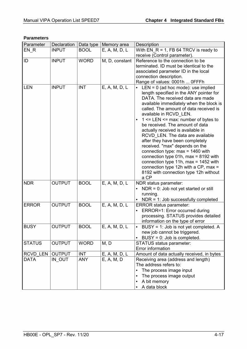
Manual VIPA Operation List SPEED7 Chapter 4 Integrated Standard FBs
HB00E - OPL_SP7 - Rev. 11/20 4-17
Parameter Declaration Data type Memory area Description EN_R INPUT BOOL E, A, M, D, L With EN_R = 1, FB 64 TRCV is ready to
receive (Control parameter). ID INPUT WORD M, D, constant Reference to the connection to be
terminated. ID must be identical to the associated parameter ID in the local connection description. Range of values: 0001h ... 0FFFh
LEN INPUT INT E, A, M, D, L • LEN = 0 (ad hoc mode): use implied length specified in the ANY pointer for DATA. The received data are made available immediately when the block is called. The amount of data received is available in RCVD_LEN.
• 1 <= LEN <= max: number of bytes to be received. The amount of data actually received is available in RCVD_LEN. The data are available after they have been completely received. "max" depends on the connection type: max = 1460 with connection type 01h, max = 8192 with connection type 11h, max = 1452 with connection type 12h with a CP, max = 8192 with connection type 12h without a CP
NDR OUTPUT BOOL E, A, M, D, L NDR status parameter: • NDR = 0: Job not yet started or still
running. • NDR = 1: Job successfully completed
ERROR OUTPUT BOOL E, A, M, D, L ERROR status parameter: • ERROR=1: Error occurred during
processing. STATUS provides detailed information on the type of error
BUSY OUTPUT BOOL E, A, M, D, L • BUSY = 1: Job is not yet completed. A new job cannot be triggered.
• BUSY = 0: Job is completed. STATUS OUTPUT WORD M, D STATUS status parameter:
Error information RCVD_LEN OUTPUT INT E, A, M, D, L Amount of data actually received, in bytes DATA IN_OUT ANY E, A, M, D Receiving area (address and length)
The address refers to: • The process image input • The process image output • A bit memory • A data block
Parameters

Chapter 4 Integrated Standard FBs Manual VIPA Operation List SPEED7
4-18 HB00E - OPL_SP7 - Rev. 11/20
ERROR STATUS Description
0 0000h New data were accepted. The current length of the received data is shown in RCVD_LEN.
0 7000h First call with REQ = 0, receiving not initiated 0 7001h Block is ready to receive. 0 7002h Follow-on call, job being processed
Note: during this processing the operating system writes the operating system data to the DATA receive buffer. For this reason, an error could result in inconsistent data being in the receive buffer.
1 8085h LEN parameter is greater than the largest permitted value, or you changed the value of LEN from the one that existed during the first call
1 8086h The ID parameter is not in the permitted address range 1 8088h • Target buffer (DATA) is too small
value LEN is greater than the predetermined by DATA. Troubleshooting if the connection type = 12h: Increase the destination buffer DATA.
1 80A1h Communications error: • FB 65 TCON was not yet called for the specified ID • The specified connection is currently being terminated.
Receiving over this connection is not possible. • The interface is receiving new parameters.
1 80B3h The parameter for the connection type (connection_type parameter in the connection description) is set to UDP. Please use the FB 68 TRCV.
1 80C3h The operating resources (memory) in the CPU are temporarily occupied.
1 80C4h Temporary communications error: The connection is currently being terminated.
1 8922h DATA parameter: Target area invalid: area does not exist in DB. 1 8924h DATA parameter: Range error in ANY pointer 1 8932h DATA parameter: DB number too large. 1 893Ah DATA parameter: Access to receive buffer not possible
(e.g. due to deleted DB) 1 897Fh DATA parameter: Internal error, such as an invalid ANY reference
Error information
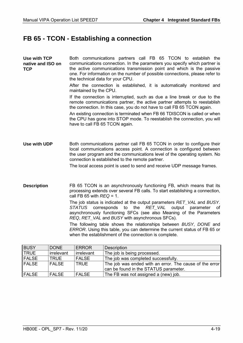
Manual VIPA Operation List SPEED7 Chapter 4 Integrated Standard FBs
HB00E - OPL_SP7 - Rev. 11/20 4-19
FB 65 - TCON - Establishing a connection
Both communications partners call FB 65 TCON to establish the communications connection. In the parameters you specify which partner is the active communications transmission point and which is the passive one. For information on the number of possible connections, please refer to the technical data for your CPU. After the connection is established, it is automatically monitored and maintained by the CPU. If the connection is interrupted, such as due a line break or due to the remote communications partner, the active partner attempts to reestablish the connection. In this case, you do not have to call FB 65 TCON again. An existing connection is terminated when FB 66 TDISCON is called or when the CPU has gone into STOP mode. To reestablish the connection, you will have to call FB 65 TCON again.
Both communications partner call FB 65 TCON in order to configure their local communications access point. A connection is configured between the user program and the communications level of the operating system. No connection is established to the remote partner. The local access point is used to send and receive UDP message frames.
FB 65 TCON is an asynchronously functioning FB, which means that its processing extends over several FB calls. To start establishing a connection, call FB 65 with REQ = 1. The job status is indicated at the output parameters RET_VAL and BUSY. STATUS corresponds to the RET_VAL output parameter of asynchronously functioning SFCs (see also Meaning of the Parameters REQ, RET_VAL and BUSY with asynchronous SFCs). The following table shows the relationships between BUSY, DONE and ERROR. Using this table, you can determine the current status of FB 65 or when the establishment of the connection is complete.
BUSY DONE ERROR Description TRUE irrelevant irrelevant The job is being processed. FALSE TRUE FALSE The job was completed successfully. FALSE FALSE TRUE The job was ended with an error. The cause of the error
can be found in the STATUS parameter. FALSE FALSE FALSE The FB was not assigned a (new) job.
Use with TCP native and ISO on TCP
Use with UDP
Description

Chapter 4 Integrated Standard FBs Manual VIPA Operation List SPEED7
4-20 HB00E - OPL_SP7 - Rev. 11/20
Parameter Declaration Data type Memory area Description REQ INPUT BOOL E, A, M, D, L Control parameter REQUEST,
initiates establishing the connection at rising edge.
ID INPUT WORD M, D, constant Reference to the connection to be established to the remote partner or between the user program and the communications level of the operating system. ID must be identical to the associated parameter ID in the local connection description. Range of values: 0001h ... 0FFFh
DONE OUTPUT BOOL E, A, M, D, L DONE status parameter: • 0: Job not yet started or still
running. • 1: Job executed without error.
BUSY OUTPUT BOOL E, A, M, D, L • BUSY = 1: Job is not yet completed.
• BUSY = 0: Job is completed. ERROR OUTPUT BOOL E, A, M, D, L ERROR status parameter:
• ERROR = 1: Error occurred during processing. STATUS provides detailed information on the type of error.
STATUS OUTPUT WORD M, D STATUS status parameter: Error information
CONNECT IN_OUT ANY D Pointer to the associated connection description (UDT 65), see Assigning Parameters for Communications Connections with TCP native and ISO on TCP and Assigning Parameters for the Local Communications Access Point with UDP.
Parameters

Manual VIPA Operation List SPEED7 Chapter 4 Integrated Standard FBs
HB00E - OPL_SP7 - Rev. 11/20 4-21
ERROR STATUS Explanation 0 0000h Connection was able to be established 0 7000h Call with REQ = 0, establishment of connection not initiated 0 7001h First call with REQ = 1, connection being established 0 7002h Follow-on call (REQ irrelevant), connection being established 1 8086h The ID parameter must not have value of zero. 0 8087h Maximal number of connections reached; no additional connection
possible 1 809Bh The local_device_id in the connection description does not match the
target CPU. 1 80A3h Attempt being made to re-establish an existing connection. 1 80A7h Communications error: you have called TDISCON before TCON was
complete. TDISCON must first complexly terminate the connection referenced by the ID.
1 80B3h Inconsistent parameters: • Error in the connection description • Local port (parameter local_tsap_id) is already present in another
connection description • ID in the connection description different from the ID specified as
parameter 1 80B4h When using the protocol variant ISO on TCP (connection_type = 12h)
for passive establishment of a connection (active_est = FALSE), you violated one or both of the following conditions: "local_tsap_id_len >= 02h" and/or "local_tsap_id[1] = E0h".
1 80C3h Temporary lack of resources in the CPU. 1 80C4h Temporary communications error:
• The connection cannot be established at this time. • The interface is receiving new parameters.
1 8722h CONNECT parameter: Source area invalid: area does not exist in DB 1 8732h CONNECT parameter: The DB number lies outside the CPU-specific
number range. 1 873Ah CONNECT parameter: Access to connection description not possible
(e.g. DB not available) 1 877Fh CONNECT parameter: Internal error such as an invalid ANY reference
Error information

Chapter 4 Integrated Standard FBs Manual VIPA Operation List SPEED7
4-22 HB00E - OPL_SP7 - Rev. 11/20
FB 66 - TDISCON - Terminating a connection
FB 66 TDISCON terminates a communications connection from the CPU to a communications partner.
The FB 66 TDISCON closes the local communications access point. The connection between the user program and the communications level of the operating system is terminated.
FB 66 TDISCON is an asynchronously functioning FB, which means that its processing extends over several FB calls. To start terminating a connection, call FB 66 with REQ = 1. After FB 66 TDISCON has been successfully called, the ID specified for FB 65 TCON is no longer valid and thus cannot be used for sending or receiving. The job status is indicated at the output parameters RET_VAL and BUSY. STATUS corresponds to the RET_VAL output parameter of asynchronously functioning SFCs (see also Meaning of the Parameters REQ, RET_VAL and BUSY with asynchronous SFCs). The following table shows the relationships between BUSY, DONE and ERROR. Using this table, you can determine the current status of FB 66 or when the establishment of the connection is complete.
BUSY DONE ERROR Description TRUE irrelevant irrelevant The job is being processed. FALSE TRUE FALSE The job was completed successfully. FALSE FALSE TRUE The job was ended with an error. The cause of the error
can be found in the STATUS parameter. FALSE FALSE FALSE The FB was not assigned a (new) job.
Use with TCP native and ISO on TCP
Use with UDP
Description
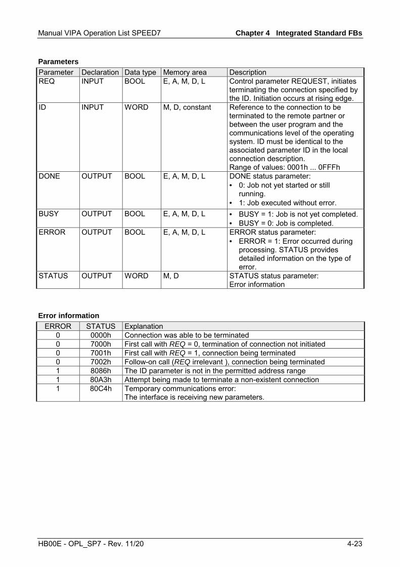
Manual VIPA Operation List SPEED7 Chapter 4 Integrated Standard FBs
HB00E - OPL_SP7 - Rev. 11/20 4-23
Parameter Declaration Data type Memory area Description REQ INPUT BOOL E, A, M, D, L Control parameter REQUEST, initiates
terminating the connection specified by the ID. Initiation occurs at rising edge.
ID INPUT WORD M, D, constant Reference to the connection to be terminated to the remote partner or between the user program and the communications level of the operating system. ID must be identical to the associated parameter ID in the local connection description. Range of values: 0001h ... 0FFFh
DONE OUTPUT BOOL E, A, M, D, L DONE status parameter: • 0: Job not yet started or still
running. • 1: Job executed without error.
BUSY OUTPUT BOOL E, A, M, D, L • BUSY = 1: Job is not yet completed. • BUSY = 0: Job is completed.
ERROR OUTPUT BOOL E, A, M, D, L ERROR status parameter: • ERROR = 1: Error occurred during
processing. STATUS provides detailed information on the type of error.
STATUS OUTPUT WORD M, D STATUS status parameter: Error information
ERROR STATUS Explanation
0 0000h Connection was able to be terminated 0 7000h First call with REQ = 0, termination of connection not initiated 0 7001h First call with REQ = 1, connection being terminated 0 7002h Follow-on call (REQ irrelevant ), connection being terminated 1 8086h The ID parameter is not in the permitted address range 1 80A3h Attempt being made to terminate a non-existent connection 1 80C4h Temporary communications error:
The interface is receiving new parameters.
Parameters
Error information
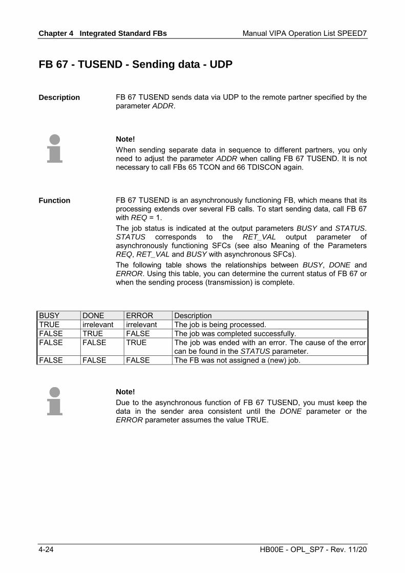
Chapter 4 Integrated Standard FBs Manual VIPA Operation List SPEED7
4-24 HB00E - OPL_SP7 - Rev. 11/20
FB 67 - TUSEND - Sending data - UDP
FB 67 TUSEND sends data via UDP to the remote partner specified by the parameter ADDR.
Note! When sending separate data in sequence to different partners, you only need to adjust the parameter ADDR when calling FB 67 TUSEND. It is not necessary to call FBs 65 TCON and 66 TDISCON again.
FB 67 TUSEND is an asynchronously functioning FB, which means that its processing extends over several FB calls. To start sending data, call FB 67 with REQ = 1. The job status is indicated at the output parameters BUSY and STATUS. STATUS corresponds to the RET_VAL output parameter of asynchronously functioning SFCs (see also Meaning of the Parameters REQ, RET_VAL and BUSY with asynchronous SFCs). The following table shows the relationships between BUSY, DONE and ERROR. Using this table, you can determine the current status of FB 67 or when the sending process (transmission) is complete.
BUSY DONE ERROR Description TRUE irrelevant irrelevant The job is being processed. FALSE TRUE FALSE The job was completed successfully. FALSE FALSE TRUE The job was ended with an error. The cause of the error
can be found in the STATUS parameter. FALSE FALSE FALSE The FB was not assigned a (new) job.
Note! Due to the asynchronous function of FB 67 TUSEND, you must keep the data in the sender area consistent until the DONE parameter or the ERROR parameter assumes the value TRUE.
Description
Function

Manual VIPA Operation List SPEED7 Chapter 4 Integrated Standard FBs
HB00E - OPL_SP7 - Rev. 11/20 4-25
Parameter Declaration Data type Memory area Description REQ INPUT BOOL E, A, M, D, L Control parameter REQUEST,
initiates the transmission at rising edge. At the first call with REQ = 1, bytes are transmitted from the area specified by the DATA parameter.
ID INPUT WORD M, D, constant Reference to the associated connection between the user program and the communication level of the operating system. ID must be identical to the associated parameter ID in the local connection description. Range of values: 0001h ... 0FFFh
LEN INPUT INT E, A, M, D, L Number of bytes to be sent with the job Range of values: 1 ... 1460
DONE OUTPUT BOOL E, A, M, D, L DONE status parameter: • 0: Job not yet started or still
running. • 1: Job executed without error
BUSY OUTPUT BOOL E, A, M, D, L • BUSY = 1: Job is not yet completed. Anew job cannot be triggered.
• BUSY = 0: Job is completed. ERROR OUTPUT BOOL E, A, M, D, L ERROR status parameter:
• ERROR = 1: Error occurred during processing. STATUS provides detailed information on the type of error
STATUS OUTPUT WORD M, D STATUS status parameter: Error information
DATA IN_OUT ANY E, A, M, D Sender area, contains address and length The address refers to: • The process image input table • The process image output table • A bit memory • A data block
ADDR IN_OUT ANY D Pointer to the address of the receiver (e.g. P#DB100.DBX0.0 byte 8), see Structure of the Address Information for the Remote Partner with UDP.
Parameters

Chapter 4 Integrated Standard FBs Manual VIPA Operation List SPEED7
4-26 HB00E - OPL_SP7 - Rev. 11/20
ERROR STATUS Description
0 0000h Send job completed without error. 0 7000h First call with REQ = 1, sending not initiated. 0 7001h First call with REQ = 1, sending initiated. 0 7002h Follow-on call (REQ irrelevant ), job being processed
Note: during this processing the operating system accesses the data in the DATA send buffer.
1 8085h LEN parameter has the value 0 or is greater than the largest permitted value.
1 8086h The ID parameter is not in the permitted address range. 0 8088h LEN parameter is larger than the memory area specified in DATA. 1 80A1h Communications error:
• FB 65 TCON was not yet called for the specified ID • The specified connection between the user program and the
communication level of the operating system is currently being terminated.
• Transmission over this connection is not possible. • The interface is being reinitialized (receiving new parameters).
1 80B3h The parameter for the connection type (connection_type parameter in the connection description) is not set to UDP. Please use the FB 63 TSEND.
1 80C3h The operating resources (memory) in the CPU are temporarily occupied.
1 80C4h Temporary communications error: • The connection between the user program and the
communication level of the operating system cannot be established at this time.
• The interface is receiving new parameters. 1 8822h DATA parameter: Source area invalid: area does not exist in DB. 1 8824h DATA parameter: Range error in ANY pointer. 1 8832h DATA parameter: DB number too large. 1 883Ah DATA parameter: Access to send buffer not possible
(e.g. due to deleted DB). 1 887Fh DATA parameter: Internal error, e.g. an invalid ANY reference.
Error information

Manual VIPA Operation List SPEED7 Chapter 4 Integrated Standard FBs
HB00E - OPL_SP7 - Rev. 11/20 4-27
FB 68 - TURCV - Receiving data - UDP
FB 68 TURCV receives data via UDP. After successful completion of FB 68 TURCV the parameter ADDR will show you the address of the remote partner (the sender). FB 68 TURCV is an asynchronously functioning FB, which means that its processing extends over several FB calls. To start sending data, call FB 68 with REQ = 1. The job status is indicated at the output parameters RET_VAL and BUSY. STATUS corresponds to the RET_VAL output parameter of asynchronously functioning SFCs (see also Meaning of the Parameters REQ, RET_VAL and BUSY with asynchronous SFCs). The following table shows the relationships between BUSY, NDR and ERROR. Using this table, you can determine the current status of FB 68 or when the receiving process is complete.
BUSY NDR ERROR Description TRUE irrelevant irrelevant The job is being processed. FALSE TRUE FALSE The job was completed successfully. FALSE FALSE TRUE The job was ended with an error. The cause of the error
can be found in the STATUS parameter. FALSE FALSE FALSE The FB was not assigned a (new) job.
Note! Due to the asynchronous function of FB 68 TURCV, the data in the receiver area are only consistent when the NDR parameter assumes the value TRUE.
Description

Chapter 4 Integrated Standard FBs Manual VIPA Operation List SPEED7
4-28 HB00E - OPL_SP7 - Rev. 11/20
Parameter Declaration Data type Memory area Description EN_R INPUT BOOL E, A, M, D, L Control parameter enabled to
receive: when EN_R = 1, FB 68 TURCV is ready to receive.
ID INPUT WORD M, D, constant Reference to the associated connection between the user program and the communication level of the operating system. ID must be identical to the associated parameter ID in the local connection description. Range of values: 0001h ... 0FFFh
LEN INPUT INT E, A, M, D, L 1 <= LEN <= 1460: number of bytes to be received. The received data are immediately available when the block is called. The amount of data received is available in RCVD_LEN.
NDR OUTPUT BOOL E, A, M, D, L NDR status parameter: • NDR = 0: Job not yet started or
still running. • NDR = 1: Job successfully
completed ERROR OUTPUT BOOL E, A, M, D, L ERROR status parameter:
• ERROR = 1: Error occurred during processing. STATUS provides detailed information on the type of error
BUSY OUTPUT BOOL E, A, M, D, L • BUSY = 1: Job is not yet completed. Anew job cannot be triggered.
• BUSY = 0: Job is completed. STATUS OUTPUT WORD M, D STATUS status parameter:
Error information RCVD_LEN OUTPUT INT E, A, M, D, L Amount of data actually received, in
bytes DATA IN_OUT ANY E, A, M, D Receiver area, contains address and
length The address refers to: • The process image input table • The process image output table • A bit memory • A data block
ADDR IN_OUT ANY D Pointer to the address of the sender (e.g.P#DB100.DBX0.0 byte 8), see Structure of the Address Information for the Remote Partner with UDP
Parameters

Manual VIPA Operation List SPEED7 Chapter 4 Integrated Standard FBs
HB00E - OPL_SP7 - Rev. 11/20 4-29
ERROR STATUS Explanation
0 0000h New data were accepted. The current length of the received data is shown in RCVD_LEN.
0 7000h First call with REQ = 0, receiving not initiated 0 7001h Block is ready to receive. 0 7002h Follow-on call, job being processed Note: during this processing the
operating system writes the operating system data to the DATA receive buffer. For this reason, an error could result in inconsistent data being in the receive buffer.
1 8085h LEN parameter is greater than the largest permitted value, or you changed the value of LEN from the one that existed during the first call
1 8086h The ID parameter is not in the permitted address range 1 8088h • Target buffer (DATA) is too small.
• The value in LEN is greater than the receiver area specified by DATA.
1 80A1h Communications error: • FB 65 TCON was not yet called for the specified ID • The specified connection between the user program and the
communication level of the operating system is currently being terminated. Receiving over this connection is not possible.
• The interface is being reinitialized (receiving new parameters). 1 80B3h The parameter for the connection type (connection_type parameter
in the connection description) is not set to UDP. Please use the FB 68 TRCV.
1 80C3h The operating resources (memory) in the CPU are temporarily occupied.
1 80C4h Temporary communications error: The connection is currently being established.
1 8922h DATA parameter: Target area invalid: area does not exist in DB. 1 8924h DATA parameter: Range error in ANY pointer 1 8932h DATA parameter: DB number too large. 1 893Ah DATA parameter: Access to receive buffer not possible
(e.g. due to deleted DB 1 897Fh DATA parameter: Internal error, such as an invalid ANY reference
Error information

Chapter 4 Integrated Standard FBs Manual VIPA Operation List SPEED7
4-30 HB00E - OPL_SP7 - Rev. 11/20

Manual VIPA Operation List SPEED7 Chapter 5 Integrated Standard SFCs
HB00E - OPL_SP7 - Rev. 11/20 5-1
Chapter 5 Integrated Standard SFCs
Here the description of the integrated standard SFCs of the SPEED7 CPUs from VIPA may be found. The description of the SFCs of the VIPA library may be found at the chapter "VIPA specific blocks".
Please note that local stack memory is occupied by using of some SFCs. This can be defined by the CPU parameters. The needed space is to be found in the following table above:
SFC Label L stack SFC 20 BLKMOV 56Byte SCF 21 FILL 56Byte SFC 47 WAIT 22Byte SFC 64 TIME_TCK 18Byte
In addition to the standard error messages the SFC 20 and SFC 21 could return the following error messages:
No. Error message Remedy 817Dh Too less local stack Increase local stack by using CPU
parameters 817Eh Range length error in
internal copy loop Check parameters
Topic Page Chapter 5 Integrated Standard SFCs .............................................. 5-1
Overview Integrated standard SFCs..................................................... 5-3 General and Specific Error Information RET_VAL................................ 5-5 SFC 0 - SET_CLK - Set system clock .................................................. 5-8 SFC 1 - READ_CLK - Read system clock ............................................ 5-9 SFC 2 ... 4 - Run-time meter .............................................................. 5-10 SFC 2 - SET_RTM - Set run-time meter............................................. 5-11 SFC 3 - CTRL_RTM - Control run-time meter .................................... 5-12 SFC 4 - READ_RTM - Read run-time meter....................................... 5-13 SFC 5 - GADR_LGC - Logical address of a channel .......................... 5-14 SFC 6 - RD_SINFO - Read start information...................................... 5-16 SFC 12 - D_ACT_DP - Activating and Deactivating of DP-Slaves...... 5-18 SFC 13 - DPNRM_DG - Read diagnostic data of a DP-slave............. 5-23 SFC 14 - DPRD_DAT - Read consistent data .................................... 5-26 SFC 15 - DPWR_DAT - Write consistent data ................................... 5-28 SFC 17 - ALARM_SQ and SFC 18 - ALARM_S ................................. 5-30 SFC 19 - ALARM_SC - Acknowledgement state last Alarm ............... 5-33
Overview
Note for needed local stack
Additional error messages of SFC 20, SFC 21
Content
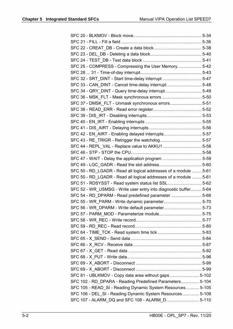
Chapter 5 Integrated Standard SFCs Manual VIPA Operation List SPEED7
5-2 HB00E - OPL_SP7 - Rev. 11/20
SFC 20 - BLKMOV - Block move........................................................ 5-34 SFC 21 - FILL - Fill a field .................................................................. 5-36 SFC 22 - CREAT_DB - Create a data block ....................................... 5-38 SFC 23 - DEL_DB - Deleting a data block.......................................... 5-40 SFC 24 - TEST_DB - Test data block ................................................ 5-41 SFC 25 - COMPRESS - Compressing the User Memory.................... 5-42 SFC 28 ... 31 - Time-of-day interrupt.................................................. 5-43 SFC 32 - SRT_DINT - Start time-delay interrupt ................................ 5-47 SFC 33 - CAN_DINT - Cancel time-delay interrupt............................. 5-48 SFC 34 - QRY_DINT - Query time-delay interrupt.............................. 5-49 SFC 36 - MSK_FLT - Mask synchronous errors................................. 5-50 SFC 37 - DMSK_FLT - Unmask synchronous errors.......................... 5-51 SFC 38 - READ_ERR - Read error register........................................ 5-52 SFC 39 - DIS_IRT - Disabling interrupts............................................. 5-53 SFC 40 - EN_IRT - Enabling interrupts .............................................. 5-55 SFC 41 - DIS_AIRT - Delaying interrupts ........................................... 5-56 SFC 42 - EN_AIRT - Enabling delayed interrupts............................... 5-57 SFC 43 - RE_TRIGR - Retrigger the watchdog.................................. 5-57 SFC 44 - REPL_VAL - Replace value to AKKU1................................ 5-58 SFC 46 - STP - STOP the CPU.......................................................... 5-58 SFC 47 - WAIT - Delay the application program ................................ 5-59 SFC 49 - LGC_GADR - Read the slot address................................... 5-60 SFC 50 - RD_LGADR - Read all logical addresses of a module ........ 5-61 SFC 50 - RD_LGADR - Read all logical addresses of a module ........ 5-61 SFC 51 - RDSYSST - Read system status list SSL............................ 5-62 SFC 52 - WR_USMSG - Write user entry into diagnostic buffer......... 5-64 SFC 54 - RD_DPARM - Read predefined parameter ......................... 5-68 SFC 55 - WR_PARM - Write dynamic parameter............................... 5-70 SFC 56 - WR_DPARM - Write default parameter............................... 5-73 SFC 57 - PARM_MOD - Parameterize module................................... 5-75 SFC 58 - WR_REC - Write record...................................................... 5-77 SFC 59 - RD_REC - Read record....................................................... 5-80 SFC 64 - TIME_TCK - Read system time tick .................................... 5-83 SFC 65 - X_SEND - Send data .......................................................... 5-84 SFC 66 - X_RCV - Receive data ........................................................ 5-87 SFC 67 - X_GET - Read data ............................................................ 5-92 SFC 68 - X_PUT - Write data............................................................. 5-96 SFC 69 - X_ABORT - Disconnect ...................................................... 5-99 SFC 69 - X_ABORT - Disconnect ...................................................... 5-99 SFC 81 - UBLKMOV - Copy data area without gaps ........................ 5-102 SFC 102 - RD_DPARA - Reading Predefined Parameters............... 5-104 SFC 105 - READ_SI - Reading Dynamic System Resources........... 5-105 SFC 106 - DEL_SI - Reading Dynamic System Resources.............. 5-108 SFC 107 - ALARM_DQ and SFC 108 - ALARM_D........................... 5-110

Manual VIPA Operation List SPEED7 Chapter 5 Integrated Standard SFCs
HB00E - OPL_SP7 - Rev. 11/20 5-3
Overview Integrated standard SFCs
The following standard system functions (SFCs) are available:
SFC Label Description SFC 0 SET_CLK Set time SFC 1 READ_CLK Read time SFC 2 SET_RTM Set operating hour counter SFC 3 CTRL_RTM Start/stop operating hour counter SFC 4 READ_RTM Read operating hour counter SFC 5 GADR_LGC Search logical address of a channel (only modules in rack 0) SFC 6 RD_SINFO Read start information of the current OB SFC 12 D_ACT_DP Activate or deactivate DP slaves SFC 13 DPNRM_DG Read slave diagnostic data SFC 14 DPRD_DAT Read consistent user data
(also from DP slaves → DP master FW ≥ V3.00) SFC 15 DPWR_DAT Write consistent user data
(also to DP slaves → DP master FW ≥ V3.00) SCF 17 ALARM_SQ Create acknowledgeable block related messages SFC 18 ALARM_S Create not acknowledgeable block related messages SFC 19 ALARM_SC Acknowledgement state of the last Alarm SQ-arrived-message SFC 20 1) BLKMOV Copy variable within work memory SFC 21 1) FILL Preset field within work memory SFC 22 CREAT_DB Create data block SFC 23 DEL_DB Delete data block SFC 25 COMPRESS Compressing the user memory SFC 24 TEST_DB Test data block SFC 28 SET_TINT Set time interrupt SFC 29 CAN_TINT Cancel time interrupt SFC 30 ACT_TINT Activate time interrupt SFC 31 QRY_TINT Request time interrupt SFC 32 SRT_DINT Start delay interrupt SFC 33 CAN_DINT Cancel delay interrupt SFC 34 QRY_DINT Request delay interrupt SFC 36 MSK_FLT Mask synchronal error event SFC 37 DMSK_FLT De-mask synchronal error event SFC 38 READ_ERR Read event status register SFC 39 DIS_IRT Disabling interrupts SFC 40 EN_IRT Enabling interrupts SFC 41 DIS_AIRT Delay of interrupt events SFC 42 EN_AIRT Abrogate delay of interrupt events SFC 43 RE_TRIGR Re-trigger cycle time control SFC 44 REPL_VAL Transfer replacement value to AKKU1 SFC 46 STP Switch CPU in STOP SFC 47 1) WAIT Delay program execution additionally to wait time SFC 49 LGC_GADR Search plug-in location of a logical address SFC 50 RD_LGADR Search all logical addresses of a module
continued ...
Standard SFCs

Chapter 5 Integrated Standard SFCs Manual VIPA Operation List SPEED7
5-4 HB00E - OPL_SP7 - Rev. 11/20
... continue Standard SFCs SFC Label Description SFC 51 RDSYSST Read information from the system state list SFC 52 WR_USMSG Write user entry in diagnostic buffer
(send via MPI in preparation) SFC 54 RD_DPARM Read predefined parameters SFC 55 WR_PARM Write dynamic parameters
(only for analog-, digital modules, FMs, CPs and via PROFIBUS DP-V1 possible)
SFC 56 WR_DPARM Write predefined parameters (only for analog-, digital modules, FMs, CPs and via PROFIBUS DP-V1 possible)
SFC 57 PARM_MOD Parameterize module (only for analog-, digital modules, FMs, CPs and via PROFIBUS DP-V1 possible)
SFC 58 WR_REC Write record set (only for analog-, digital modules, FMs, CPs and via PROFIBUS DP-V1 possible)
SFC 59 RD_REC Read record set (only for analog-, digital modules, FMs, CPs and via PROFIBUS DP-V1 possible)
SFC 64 1) TIME_TCK Read millisecond timer SFC 65 X_SEND Send data to external partner SFC 66 X_RCV Receive data from external partner SFC 67 X_GET Read data from external partner SFC 68 X_PUT Write data to external partner SFC 69 X_ABORT Interrupt connection to external partner SFC 81 UBLKMOV Copy variable non-interruptible SFC 102 RD_DPARA Redefined parameters SFC 105 READ_SI Reading dynamic system resources SFC 106 DEL_SI Deleting dynamic system resources SFC 107 ALARM_DQ Generating always acknowledgeable and block-related messages SFC 108 ALARM_D Generating always acknowledgeable and block-related messages
1) This function block is interruptable and does not affect the interrupt reaction time.
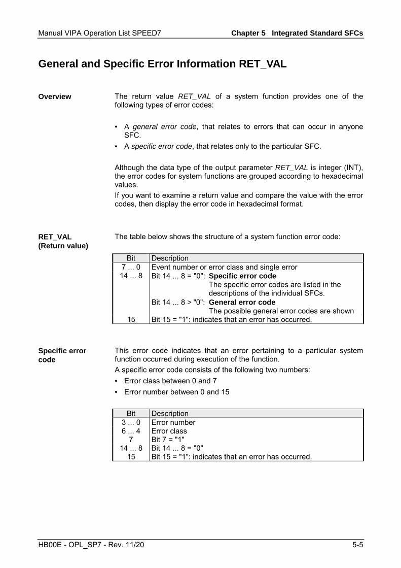
Manual VIPA Operation List SPEED7 Chapter 5 Integrated Standard SFCs
HB00E - OPL_SP7 - Rev. 11/20 5-5
General and Specific Error Information RET_VAL
The return value RET_VAL of a system function provides one of the following types of error codes: • A general error code, that relates to errors that can occur in anyone
SFC. • A specific error code, that relates only to the particular SFC. Although the data type of the output parameter RET_VAL is integer (INT), the error codes for system functions are grouped according to hexadecimal values. If you want to examine a return value and compare the value with the error codes, then display the error code in hexadecimal format.
The table below shows the structure of a system function error code:
Bit Description 7 ... 0 Event number or error class and single error
14 ... 8 Bit 14 ... 8 = "0": Specific error code The specific error codes are listed in the descriptions of the individual SFCs. Bit 14 ... 8 > "0": General error code The possible general error codes are shown
15 Bit 15 = "1": indicates that an error has occurred.
This error code indicates that an error pertaining to a particular system function occurred during execution of the function. A specific error code consists of the following two numbers: • Error class between 0 and 7 • Error number between 0 and 15
Bit Description 3 ... 0 Error number 6 ... 4 Error class
7 Bit 7 = "1" 14 ... 8 Bit 14 ... 8 = "0"
15 Bit 15 = "1": indicates that an error has occurred.
Overview
RET_VAL (Return value)
Specific error code

Chapter 5 Integrated Standard SFCs Manual VIPA Operation List SPEED7
5-6 HB00E - OPL_SP7 - Rev. 11/20
The parameter RET_VAL of some SFCs only returns general error information. No specific error information is available. The general error code contains error information that can result from any system function. The general error code consists of the following two numbers: • A parameter number between 1 and 111, where 1 indicates the first
parameter of the SFC that was called, 2 the second etc. • An event number between 0 and 127. The event number indicates that a
synchronous fault has occurred.
Bit Description 7 ... 0 Event number 14 ... 8 Parameter number
15 Bit 15 = "1": indicates that an error has occurred. The following table explains the general error codes associated with a return value. Error codes are shown as hexadecimal numbers. The x in the code number is only used as a placeholder. The number represents the parameter of the system function that has caused the error.
Error code Description
8x7Fh Internal Error. This error code indicates an internal error at parameter x. This error did not result from the actions if the user and he/she can therefore not resolve the error.
8x22h Area size error when a parameter is being read. 8x23h Area size error when a parameter is being written. This error code indicates that
parameter x is located either partially or fully outside of the operand area or that the length of the bit-field for an ANY-parameter is not divisible by 8.
8x24h Area size error when a parameter is being read. 8x25h Area size error when a parameter is being written. This error code indicates that
parameter x is located in an area that is illegal for the system function. The description of the respective function specifies the areas that are not permitted for the function.
8x26h The parameter contains a number that is too high for a time cell. This error code indicates that the time cell specified in parameter x does not exist.
8x27h The parameter contains a number that is too high for a counter cell (numeric fields of the counter). This error code indicates that the counter cell specified in parameter x does not exist.
continued ...
General error codes RET_VAL
General error codes

Manual VIPA Operation List SPEED7 Chapter 5 Integrated Standard SFCs
HB00E - OPL_SP7 - Rev. 11/20 5-7
... continue Error code Description
8x28h Orientation error when reading a parameter. 8x29h Orientation error when writing a parameter. This error code indicates that the
reference to parameter x consists of an operand with a bit address that is not equal to 0.
8x30h The parameter is located in the write-protected global-DB. 8x31h The parameter is located in the write-protected instance-DB. This error code
indicates that parameter x is located in a write-protected data block. If the data block was opened by the system function itself, then the system function will always return a value 8x30h.
8x32h The parameter contains a DB-number that is too high (number error of the DB). 8x34h The parameter contains a FC-number that is too high (number error of the FC). 8x35h The parameter contains a FB-number that is too high (number error of the FB).
This error code indicates that parameter x contains a block number that exceeds the maximum number permitted for block numbers.
8x3Ah The parameter contains the number of a DB that was not loaded. 8x3Ch The parameter contains the number of a FC that was not loaded. 8x3Eh The parameter contains the number of a FB that was not loaded. 8x42h An access error occurred while the system was busy reading a parameter from
the peripheral area of the inputs. 8x43h An access error occurred while the system was busy writing a parameter into den
peripheral area of the outputs. 8x44h Error during the n-th (n > 1) read access after an error has occurred. 8x45h Error during the n-th (n > 1) write access after an error has occurred. This error
code indicates that access was denied to the requested parameter.

Chapter 5 Integrated Standard SFCs Manual VIPA Operation List SPEED7
5-8 HB00E - OPL_SP7 - Rev. 11/20
SFC 0 - SET_CLK - Set system clock
The SFC 0 SET_CLK (set system clock) sets the time of day and the date of the clock in the CPU. The clock continues running from the new time and date. If the clock is a master clock then the call to SFC 0 will start a clock synchronization cycle as well. The clock synchronization intervals are defined by hardware settings.
Parameter Declaration Data type Memory block Description PDT INPUT DT D, L Enter the new date and time at PDT. RET_VAL OUTPUT INT I, Q, M, D, L When an error occurs while the function
is being processed then the returned value contains the respective error code.
Date and time are entered as data type DT. Example: date: 04.27.2006, time: 14:15:55 → DT#2006-04-27-14:15:55. The time can only be entered with one-second accuracy. The day of the week is calculated automatically by SFC 0. Remember that you must first create the data type DT by means of FC 3 D_TOD_DT before you can supply it to the input parameter (see time functions; FC 3, FC 6, FC 7, FC 8, FC 33, FC 40, FC 1, FC 35, FC 34).
Value Description 0000h no error 8080h error in the date 8081h error in the time
Description
Parameters
PDT
RET_VAL (Return value)

Manual VIPA Operation List SPEED7 Chapter 5 Integrated Standard SFCs
HB00E - OPL_SP7 - Rev. 11/20 5-9
SFC 1 - READ_CLK - Read system clock
The SFC 1 READ_CLK (read system clock) reads the contents of the CPU clock. This returns the current time and date.
Parameter Declaration Data type Memory block Description RET_VAL OUTPUT INT I, Q, M, D, L If an error occurs when this function is
being processed the return value contains the error code.
CDT OUTPUT DT D, L The current date and time are available at output CDT.
SFC 1 does not return any specific error information.
The current date and time are available at output CDT.
Description
Parameters
RET_VAL (Return value)
CDT

Chapter 5 Integrated Standard SFCs Manual VIPA Operation List SPEED7
5-10 HB00E - OPL_SP7 - Rev. 11/20
SFC 2 ... 4 - Run-time meter
VIPA CPUs have 8 run-time meters. You can use: SFC 2 SET_RTM set run-time meter SFC 3 CTRL_RTM run-time meter starting / stopping SFC 4 READ_RTM read run-time meter
You can use a runtime meter for a variety of applications: • for measuring the runtime of a CPU • for measuring the runtime of controlled equipment or connected
devices.
When it is started, the runtime meter begins to count starting at the last recorded value. If you want it to start at a different initial value, you must explicitly specify this value with the SFC 2. If the CPU changes to the STOP mode, or you stop the runtime meter, the CPU records the current value of the runtime meter. When a restart of the CPU is executed, the runtime meter must be restarted with the SFC 3.
The runtime meter has a range of value from 0 ... 32767 hours.
Description
Characteristics
Range of values
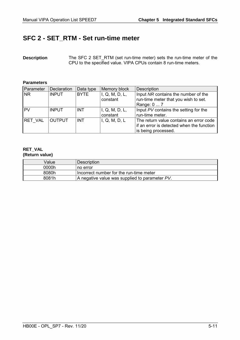
Manual VIPA Operation List SPEED7 Chapter 5 Integrated Standard SFCs
HB00E - OPL_SP7 - Rev. 11/20 5-11
SFC 2 - SET_RTM - Set run-time meter
The SFC 2 SET_RTM (set run-time meter) sets the run-time meter of the CPU to the specified value. VIPA CPUs contain 8 run-time meters.
Parameter Declaration Data type Memory block Description NR INPUT BYTE I, Q, M, D, L,
constant Input NR contains the number of the run-time meter that you wish to set. Range: 0 ... 7
PV INPUT INT I, Q, M, D, L, constant
Input PV contains the setting for the run-time meter.
RET_VAL OUTPUT INT I, Q, M, D, L The return value contains an error code if an error is detected when the function is being processed.
Value Description 0000h no error 8080h Incorrect number for the run-time meter 8081h A negative value was supplied to parameter PV.
Description
Parameters
RET_VAL (Return value)

Chapter 5 Integrated Standard SFCs Manual VIPA Operation List SPEED7
5-12 HB00E - OPL_SP7 - Rev. 11/20
SFC 3 - CTRL_RTM - Control run-time meter
The SFC 3 CTRL_RTM (control run-time meter) starts or stops the run-time meter depending on the status of input S.
Parameter Declaration Data type Memory block Description NR INPUT BYTE I, Q, M, D, L,
constant Input NR contains the number of the run-time meter that you wish to set. Range: 0 ... 7
S INPUT BOOL I, Q, M, D, L, constant
Input S starts or stops the run-time meter. Set this signal to "0" to stop the run-time meter. Set this signal to "1" to start the run-time meter.
RET_VAL OUTPUT INT I, Q, M, D, L
The return value contains an error code if an error is detected when the function is being processed.
Value Description 0000h no error 8080h Incorrect number for the run-time meter
Description
Parameters
RET_VAL (Return value)

Manual VIPA Operation List SPEED7 Chapter 5 Integrated Standard SFCs
HB00E - OPL_SP7 - Rev. 11/20 5-13
SFC 4 - READ_RTM - Read run-time meter
The SFC 4 READ_RTM (read run-time meter) reads the contents of the run-time meter. The output data indicates the current run-time and the status of the meter ("stopped" or "started"). When the run-time meter has been active for more than 32767 hours it will stop with this value and return value RET_VAL indicates the error message "8081h: overflow".
Parameter Declaration Data type Memory block Description NR INPUT BYTE I, Q, M, D, L,
constant Input NR contains the number of the run-time meter that you wish to read. Range: 0 ... 7
RET_VAL OUTPUT INT I, Q, M, D, L The return value contains an error code if an error is detected when the function is being processed.
CQ OUTPUT BOOL I, Q, M, D, L Output CQ indicates whether the run-time meter is started or stopped. • "0": the status of the run-time meter
is stopped. • "1": the status of the run-time meter
is started. CV OUTPUT INT I, Q, M, D, L Output CV indicates the up to date
value of the run-time meter.
Value Description 0000h no error 8080h Incorrect number for the run-time meter 8081h run-time meter overflow
Description
Parameters
RET_VAL (Return value)
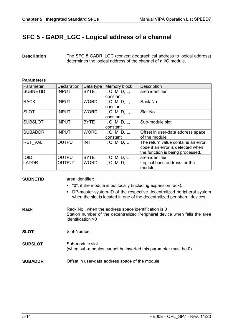
Chapter 5 Integrated Standard SFCs Manual VIPA Operation List SPEED7
5-14 HB00E - OPL_SP7 - Rev. 11/20
SFC 5 - GADR_LGC - Logical address of a channel
The SFC 5 GADR_LGC (convert geographical address to logical address) determines the logical address of the channel of a I/O module.
Parameter Declaration Data type Memory block Description SUBNETID INPUT BYTE I, Q, M, D, L,
constant area identifier
RACK INPUT WORD I, Q, M, D, L, constant
Rack No.
SLOT INPUT WORD I, Q, M, D, L, constant
Slot-No.
SUBSLOT INPUT BYTE I, Q, M, D, L, constant
Sub-module slot
SUBADDR INPUT WORD I, Q, M, D, L, constant
Offset in user-data address space of the module
RET_VAL OUTPUT INT I, Q, M, D, L
The return value contains an error code if an error is detected when the function is being processed.
IOID OUTPUT BYTE I, Q, M, D, L area identifier LADDR OUTPUT WORD I, Q, M, D, L Logical base address for the
module area identifier: • "0": if the module is put locally (including expansion rack). • DP-master-system-ID of the respective decentralized peripheral system
when the slot is located in one of the decentralized peripheral devices. Rack No., when the address space identification is 0 Station number of the decentralized Peripheral device when falls the area identification >0 Slot-Number Sub-module slot (when sub-modules cannot be inserted this parameter must be 0) Offset in user-data address space of the module
Description
Parameters
SUBNETID
Rack
SLOT
SUBSLOT
SUBADDR

Manual VIPA Operation List SPEED7 Chapter 5 Integrated Standard SFCs
HB00E - OPL_SP7 - Rev. 11/20 5-15
The return value contains an error code if an error is detected when the function is being processed.
Value Description 0000h no error 8094h No subnet with the specified SUBNETID configured. 8095h Illegal value for parameter RACK 8096h Illegal value for parameter SLOT 8097h Illegal value for parameter SUBSLOT 8098h Illegal value for parameter SUBADDR 8099h The slot has not been configured. 809Ah The sub address for the selected slot has not been configured.
Area identifier: • 54h: peripheral input (PI) • 55h: peripheral output (PQ) For hybrid modules the SFC returns the area identification of the lower address. When the addresses are equal the SFC returns identifier 54h.
Logical base address for the module
RET_VAL (Return value)
IOID
LADDR

Chapter 5 Integrated Standard SFCs Manual VIPA Operation List SPEED7
5-16 HB00E - OPL_SP7 - Rev. 11/20
SFC 6 - RD_SINFO - Read start information
The SFC 6 RD_SINFO (read start information) retrieves the start information of the last OB accessed and that has not yet been processed completely, as well as the last startup OB. These start information items do not contain a time stamp. Two identical start information items will be returned when the call is issued from OB 100.
Parameter Declaration Data type Memory block Description RET_VAL OUTPUT INT I, Q, M, D, L The return value contains an error
code if an error is detected when the function is being processed.
TOP_SI OUTPUT STRUCT D, L Start information of the current OB START_UP_SI OUTPUT STRUCT D, L Start information of the last OB that
was started
This refers to two identical structures as shown below.
Structure element
Data type Description
EV_CLASS BYTE Bits 3 ... 0: event identifier Bits 7 ... 4: event class 1: Start events of standard-OBs 2: Start events of synchronous-error OBs 3: Start events of asynchronous-error OBs
EV_NUM BYTE event number PRIORITY BYTE Number defining the priority level NUM BYTE Structure element NUM contains the number of the current OB or
of the last OB started TYP2_3 BYTE Data identifier 2_3: identifies the information entered into ZI2_3 TYP1 BYTE Data identifier 1: identifies the information entered into ZI1 ZI1 WORD Additional information 1 ZI2_3 DWORD Additional information 2_3
Description
Parameters
TOP_SI and START_UP_SI

Manual VIPA Operation List SPEED7 Chapter 5 Integrated Standard SFCs
HB00E - OPL_SP7 - Rev. 11/20 5-17
Note! The content of the structure elements shown in the table above corresponds exactly with the temporary variables of an OB. It must be remembered, however, that the name and the data type of the temporary variables in the different OBs might differ. Furthermore, the call interface of the OBs also contains the date and time at which call to the OB was requested. The SFC 6 only returns general error information. No specific error information is available. The OB that was called last and that has not yet been completely processed serves as OB 80; the restart OB that was started last serves as OB 100. The following table shows the assignment of the structure elements of parameter TOP_SI of SFC 6 and the respective local variables of OB 80. TOP_SI Structure element
Data type Logical Variable Data type
EV_CLASS BYTE OB100_EV_CLASS BYTE EV_NUM BYTE OB80_FLT_ID BYTE PRIORITY BYTE OB80_PRIORITY BYTE NUM BYTE OB80_OB_NUMBR BYTE TYP2_3 BYTE OB80_RESERVED_1 BYTE TYP1 BYTE OB80_ RESERVED_2 BYTE ZI1 WORD OB80_ERROR_INFO WORD ZI2_3 DWORD OB80_ERR_EV_CLASS
OB80_ERR_EV_NUM OB80_OB_PRIORITY OB80_OB_NUM
BYTE BYTE BYTE BYTE
The following table shows the assignment of the structure elements of parameter START_UP_SI of SFC 6 and the respective local variables of OB 100. START_UP_SI Structure element
Data type Logical Variable Data type
EV_CLASS BYTE OB100_EV_CLASS BYTE EV_NUM BYTE OB100_STRTUP BYTE PRIORITY BYTE OB100_PRIORITY BYTE NUM BYTE OB100_OB_NUMBR BYTE TYP2_3 BYTE OB100_RESERVED_1 BYTE TYP1 BYTE OB100_ RESERVED_2 BYTE ZI1 WORD OB100_STOP WORD ZI2_3 DWORD OB100_STRT_INFO DWORD
RET_VAL (Return value)
Example

Chapter 5 Integrated Standard SFCs Manual VIPA Operation List SPEED7
5-18 HB00E - OPL_SP7 - Rev. 11/20
SFC 12 - D_ACT_DP - Activating and Deactivating of DP-Slaves
With the SFC 12 D_ACT_DP, you can specifically deactivate and reactivate configured DP slaves. In addition, you can determine whether each assigned DP slave is currently activated or deactivated. The SFC 12 cannot be used on PROFIBUS PA field devices, which are connected by a DP/PA link to a DP master system.
Note! As long as any SFC 12 job is busy you cannot download a modified configuration from your PG to the CPU. The CPU rejects initiation of an SFC 12 request when it receives the download of a modified configuration.
If you configure DP slaves in a CPU, which are not actually present or not currently required, the CPU will nevertheless continue to access these DP slaves at regular intervals. After the slaves are deactivated, further CPU accessing will stop. In this way, the fastest possible DP bus cycle can be achieved and the corresponding error events no longer occur.
Every one of the possible machine options is configured as a DP slave by the manufacturer in order to create and maintain a common user program having all possible options. With the SFC 12, you can deactivate all DP slaves, which are not present at machine startup.
The SFC 12 operates asynchronously, in other words, it is executed over several SFC calls. You start the request by calling the SFC 12 with REQ = 1. The status of the job is indicated by the output parameters RET_VAL and BUSY.
If you have started a deactivation or activation job and you call the SFC 12 again before the job is completed, the way in which the SFC reacts depends largely on whether the new call involves the same job: if the parameter LADDR matches, the SFC call is interpreted as a follow-on call.
Description
Application
Example
How the SFC operates
Identifying a job

Manual VIPA Operation List SPEED7 Chapter 5 Integrated Standard SFCs
HB00E - OPL_SP7 - Rev. 11/20 5-19
When you deactivate a DP slave with the SFC 12, its process outputs are set to the configured substitute values or to "0" (secure state). The assigned DP master does not continue to address this DP slave. Deactivated DP slaves are not identified as fault or missing by the error LEDs on the DP master or CPU. The process image of the inputs of deactivated DP slaves is updated with 0, that is, it is handled just as for failed DP slaves.
Note! With VIPA you can not deactivate all DP slaves. At least 1 slave must remain activated at the bus.
If you are using your program to directly access the user data of a previously deactivated DP slave, the I/O access error OB (OB 122) is called, and the corresponding start event is entered in the diagnostic buffer. If you attempt to access a deactivated DP slave with SFC (i.e. SFC 59 RD_REC), you receive the error information in RET_VAL as for an unavailable DP slave. Deactivating a DP slaves OB 85, even if its inputs or outputs belong to the system-side process image to be updated. No entry is made in the diagnostic buffer. Deactivating a DP slave does not start the slave failure OB 86, and the operating system also does not make an entry in the diagnostic buffer. If a DP station fails after you have deactivated it with the SFC 12, the operating system does not detect the failure. As a result, there is no subsequent start of OB 86 or diagnostic buffer entry. The station failure is detected only after the station has been reactivated and indicated in RET_VAL. If you wish to deactivate DP slaves functioning as transmitters in cross communication, we recommend that you first deactivate the receivers (listeners) that detect, which input data the transmitter is transferring to its DP master. Deactivate the transmitter only after you have performed this step.
Deactivating DP slaves
Chapter 5 Integrated Standard SFCs Manual VIPA Operation List SPEED7
5-20 HB00E - OPL_SP7 - Rev. 11/20
When you reactivate a DP slave with the SFC 12 it is configured and assigned parameters by the designated DP master (as with the return of a failed station). This activation is completed when the slave is able to transfer user data. Activating a DP slaves does not start the program error OB 85, even if its inputs or outputs belong to the system-side process image to be updated. An entry in the diagnostic buffer is also not made. Activating a DP slave does not start the slave failure OB 86, and the operating system also does not make an entry in the diagnostic buffer. If you attempt to use the SFC 12 to activate a slave, who has been deactivated and is physically separated from the DP bus, a supervision time of 10sec expires. After this monitoring period has expired, the SFC returns the error message 80A2h. The slave remains deactivated. If the slave is reconnected to the DP bus at a later time, it must be reactivated with the SFC 12.
Note! Activating a DP slave may be time-consuming. Therefore, if you wish to cancel a current activation job, start the SFC 12 again with the same value for LADDR and MODE = 2. Repeat the call of the SFC 12 until successful cancellation of the activation is indicated by RET_VAL = 0.
If you wish to activate DP slaves which take part in the cross communication, we recommend that you first activate the transmitters and then the receivers (listeners).
At a restart the slaves are activated automatically. After the CPU start-up, the CPU cyclically attempts to contact all configured and not deactivated slaves that are either not present or not responding.
Note! The startup OB 100 does not support the call of the SFC 12.
Activating DP slaves
CPU startup
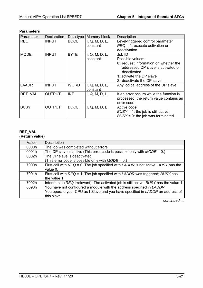
Manual VIPA Operation List SPEED7 Chapter 5 Integrated Standard SFCs
HB00E - OPL_SP7 - Rev. 11/20 5-21
Parameter Declaration Data type Memory block Description REQ INPUT BOOL I, Q, M, D, L,
constant Level-triggered control parameter REQ = 1: execute activation or deactivation
MODE INPUT BYTE I, Q, M, D, L, constant
Job ID Possible values: 0: request information on whether the addressed DP slave is activated or deactivated. 1: activate the DP slave 2: deactivate the DP slave
LAADR INPUT WORD I, Q, M, D, L, constant
Any logical address of the DP slave
RET_VAL OUTPUT INT I, Q, M, D, L If an error occurs while the function is processed, the return value contains an error code.
BUSY OUTPUT BOOL I, Q, M, D, L Active code: BUSY = 1: the job is still active. BUSY = 0: the job was terminated.
Value Description 0000h The job was completed without errors. 0001h The DP slave is active (This error code is possible only with MODE = 0.) 0002h The DP slave is deactivated
(This error code is possible only with MODE = 0.) 7000h First call with REQ = 0. The job specified with LADDR is not active; BUSY has the
value 0. 7001h First call with REQ = 1. The job specified with LADDR was triggered; BUSY has
the value 1. 7002h Interim call (REQ irrelevant). The activated job is still active; BUSY has the value 1.8090h You have not configured a module with the address specified in LADDR.
You operate your CPU as I-Slave and you have specified in LADDR an address of this slave.
continued ...
Parameters
RET_VAL (Return value)

Chapter 5 Integrated Standard SFCs Manual VIPA Operation List SPEED7
5-22 HB00E - OPL_SP7 - Rev. 11/20
... continue Value Description 8092h For the addressed DP slave no activation job is processed at the present. (This
error code is possible only with MODE = 1.) 8093h No DP slave is assigned to the address stated in LADDR (no projection submitted),
or the parameter MODE is not known. 80A1h The addressed DP slave could not be parameterized.
(This error code is possible only with MODE = 1.) Note! The SFC supplies this information only if the activated slave fails again during parameterization. If parameterization of a single module was unsuccessful the SFC returns the error information 0000h.
80A2h The addressed DP slave does not return an acknowledgement. 80A3h The DP master concerned does not support this function. 80A4h The CPU does not support this function for external DP masters. 80A6h Slot error in the DP slave; user data access not possible.
(This error code is possible only with MODE = 1.) Note! The SFC returns this error information only if the active slave fails after parameterization and before the SFC ends. If only a single module is unavailable the SFC returns the error information 0000h.
80C1h The SFC 12 was started and continued with another logical address. (This error code is possible only with MODE = 1.)
80C3h • Temporary resource error: the CPU is currently processing the maximum possible activation and deactivation jobs. (this error code is possible only with MODE = 1 and MODE = 2).
• The CPU is busy receiving a modified configuration. Currently you cannot enable/disable DP slaves.
F001h Not all slaves may be deactivated. At least 1 slave must remain activated. F002h Unknown slave address

Manual VIPA Operation List SPEED7 Chapter 5 Integrated Standard SFCs
HB00E - OPL_SP7 - Rev. 11/20 5-23
SFC 13 - DPNRM_DG - Read diagnostic data of a DP-slave
The SFC 13 DPNRM_DG (read diagnostic data of a DP-slave) reads up-to-date diagnostic data of a DP-slave. The diagnostic data of each DP-slave is defined by EN 50 170 Volume 2, PROFIBUS. Input parameter RECORD determines the target area where the data read from the slave is saved after it has been transferred without error. The read operation is started when input parameter REQ is set to 1. The following table contains information about the principal structure of the slave diagnosis. For additional information please refer to the manuals for the DP-slaves that you are using.
Byte description 0 station status 1 1 station status 2 2 station status 3 3 master-station number 4 manufacturer code (high byte) 5 manufacturer code (low byte)
6 ... additional slave-specific diagnostics
The SFC 13 is executed as asynchronous SFC, i.e. it can be active for multiple SFC-calls. Output parameters RET_VAL and BUSY indicate the status of the command as shown by the following table. Relationship between the call, REQ, RET_VAL and BUSY:
Seq. No. of the call Type of call REQ RET_VAL BUSY1 first call 1 7001h or
Error code 1 0
2 ... (n-1) intermediate call
irrelevant 7002h 1
n last call irrelevant If the command was completed without errors, then the number of bytes returned is entered as a positive number or the error code if an error did occur.
0
Description
Operation
Chapter 5 Integrated Standard SFCs Manual VIPA Operation List SPEED7
5-24 HB00E - OPL_SP7 - Rev. 11/20
Parameter Declaration Data type Memory block Description REQ INPUT BOOL I, Q, M, D, L,
constant REQ = 1: read request
LADDR INPUT WORD I, Q, M, D, L, constant
The configured diagnostic address of the DP slave
RET_VAL OUTPUT INT I, Q, M, D, L The return value contains an error code if an error is detected when the function is being processed. If no error did occur, then RET_VAL contains the length of the data that was transferred.
RECORD OUTPUT ANY I, Q, M, D, L Target area for the diagnostic data that has been read. Only data type BYTE is valid. The minimum length of the read record or respectively the target area is 6. The maximum length of the read record is 240. When the standard diagnostic data exceeds 240bytes on a norm slave and the maximum is limited to 244bytes, then only the first 240bytes are transferred into the target area and the respective overflow-bit is set in the data.
BUSY OUTPUT BOOL I, Q, M, D, L BUSY = 1: read operation has not been completed.
The CPU tests the actual length of the diagnostic data that was read: When the length of RECORD • is less than the amount of data the data is discarded and the respective
error code is entered into RET_VAL. • is larger than or equal to the amount of data then the data is transferred
into the target areas and RET_VAL is set to the actual length as a positive value.
Note! It is essential that the matching RECORD parameters are be used for all calls that belong to a single task. A task is identified clearly by input parameter LADDR and RECORD.
Parameters
RECORD
Manual VIPA Operation List SPEED7 Chapter 5 Integrated Standard SFCs
HB00E - OPL_SP7 - Rev. 11/20 5-25
The following conditions apply if the amount of standard diagnostic data of the norm slave lies between 241 and 244bytes: When the length of RECORD • is less than 240bytes the data is discarded and the respective error
code is entered into RET_VAL. • is greater than 240bytes, then the first 240bytes of the standard
diagnostic data are transferred into the target area and the respective overflow-bit is set in the data.
The return value contains an error code if an error is detected when the function is being processed. If no error did occur, then RET_VAL contains the length of the data that was transferred.
Note! The amount of read data for a DP-slave depends on the diagnostic status.
More detailed information about general error information is to be found at the beginning of this chapter. The SFC 13 specific error information consists of a subset of the error information for SFC 59 RD_REC. More detailed information is available from the help for SFC 59.
Norm slaves
RET_VAL (Return value)
Error information

Chapter 5 Integrated Standard SFCs Manual VIPA Operation List SPEED7
5-26 HB00E - OPL_SP7 - Rev. 11/20
SFC 14 - DPRD_DAT - Read consistent data
The SFC 14 DPRD_DAT (read consistent data of a DP norm slave) reads consistent data from a DP norm slave. The length of the consistent data must be three or more than four bytes, while the maximum length is 64Byte. Please refer to the manual of your specific CPU for details. Input parameter RECORD defines the target area where the read data is saved when the data transfer has been completed without errors. The length of the respective target area must be the same as the length that you have configured for the selected module. If the module consists of a DP-norm slave of modular construction or with multiple DP-identifiers, then a single SFC 14 call can only access the data of a single module / DP-identifier at the configured start address. SFC 14 is used because a load command accessing the periphery or the process image of the inputs can read a maximum of four contiguous bytes.
consistent data Consistent data is data, where the contents belongs to the same category and that may not be separated. It is, for instance, important that data returned by analog modules is always processed consistently, i.e. the value returned by analog modules must not be modified incorrectly when it is read at two different times.
Parameter Declaration Data type Memory block Description LADDR INPUT WORD I, Q, M, D, L,
constant Configured start address of the receive data buffer of the module from which the data must be read
RET_VAL OUTPUT INT I, Q, M, D, L The return value contains an error code if an error is detected when the function is being processed
RECORD OUTPUT ANY I, Q, M, D, L Target area for the user data that was read. The length must be exactly the same as the length that was configured for the selected module. Only data type BYTE is permitted.
Description
Definition
Parameters

Manual VIPA Operation List SPEED7 Chapter 5 Integrated Standard SFCs
HB00E - OPL_SP7 - Rev. 11/20 5-27
Value Description 0000h No error has occurred. 8090h You have not configured a module for the logical base address that you
have specified, or you have ignored the restrictions that apply to the length of the consistent data.
8092h The ANY-reference contains a type that is not equal to BYTE. 8093h No DP-module from which consistent data can be read exists at the
logical address that was specified under LADDR. 80A0h Incorrect start address for the address range in the transfer I/O buffer. 80B0h Slave failure at the external DP-interface 80B1h The length of the specified target area is not equal to the configured
user data length. 80B2h External DP-interface system error 80B3h External DP-interface system error 80C0h External DP-interface system error 80C2h External DP-interface system error 80Fxh External DP-interface system error 87xyh External DP-interface system error 808xh External DP-interface system error
RET_VAL (Return value)

Chapter 5 Integrated Standard SFCs Manual VIPA Operation List SPEED7
5-28 HB00E - OPL_SP7 - Rev. 11/20
SFC 15 - DPWR_DAT - Write consistent data
The SFC 15 DPWR_DAT (write consistent data to a DP-norm slave) writes consistent data that is located in parameter RECORD to the DP-norm slave. The length of the consistent data must be three or more than four bytes, while the maximum length is 64Byte. Please refer to the manual of your specific CPU for details. Data is transferred synchronously, i.e. the write process is completed when the SFC has terminated. The length of the respective source area must be the same as the length that you have configured for the selected module. If the module consists of a DP-norm slave of modular construction, then you can only access a single module of the DP-slave. The SFC 15 is used because a transfer command accessing the periphery or the process image of the outputs can write a maximum of four contiguous bytes.
Consistent data Consistent data is data, where the contents belongs to the same category and that may not be separated. For instance, it is important that data returned by analog modules is always processed consistently, i.e. the value returned by analog modules must not be modified incorrectly when it is read at two different times.
Parameter Declaration Data type Memory block Description LADDR INPUT WORD I, Q, M, D, L,
constant Configured start address of the output buffer of the module to which the data must be written
RECORD INPUT ANY I, Q, M, D, L Source area for the user data that will be written. The length must be exactly the same as the length that was configured for the selected module. Only data type BYTE is permitted.
RET_VAL OUTPUT INT I, Q, M, D, L The return value contains an error code if an error is detected when the function is being processed.
Description
Definition
Parameters
Manual VIPA Operation List SPEED7 Chapter 5 Integrated Standard SFCs
HB00E - OPL_SP7 - Rev. 11/20 5-29
Value Description 0000h No error has occurred. 8090h You have not configured a module for the logical base address that you
have specified, or you have ignored the restrictions that apply to the length of the consistent data.
8092h The ANY-reference contains a type that is not equal to BYTE. 8093h No DP-module to which consistent data can be written exists at the
logical address that was specified under LADDR. 80A1h The selected module has failed. 80B0h Slave failure at the external DP-interface 80B1h The length of the specified source area is not equal to the configured
user data length. 80B2h External DP-interface system error 80B3h External DP-interface system error 80C1h The data of the write command that was previously issued to the module
has not yet been processed. 80C2h External DP-interface system error 80Fxh External DP-interface system error 85xyh External DP-interface system error 808xh External DP-interface system error
RET_VAL (Return value)

Chapter 5 Integrated Standard SFCs Manual VIPA Operation List SPEED7
5-30 HB00E - OPL_SP7 - Rev. 11/20
SFC 17 - ALARM_SQ and SFC 18 - ALARM_S
Every call to the SFC 17 ALARM_SQ and the SFC 18 ALARM_S generates a message that can have an associated value. This message is sent to all stations that have registered for this purpose. The call to the SFC 17 and the SFC 18 can only be issued if the value of signal SIG triggering the message was inverted with respect to the previous call. If this is not true output parameter RET_VAL will contain the respective information and the message will not be sent. Input SIG must be set to "1" when the call to the SFC 17 and SFC 18 is issued for the first time, else the message will not be sent and RET_VAL will return an error code. Note! The SFC 17 and the SFC 18 should always be called from a FB after you have assigned the respective system attributes to this FB.
The SFC 17 and the SFC 18 occupy temporary memory that is also used to save the last two signal statuses with a time stamp and the associated value. When the call to the SFC occurs at a time when the signal statuses of the two most recent "valid" SFC-calls has not been sent (signal overflow), then the current signal status as well as the last signal status are discarded and an overflow-code is entered into temporary memory. The signal that occurred before the last signal will be sent as soon as possible including the overflow-code.
Messages sent by means of the SFC 17 can be acknowledged via a display device. The acknowledgement status for the last "message entering state" and the signal status of the last SFC 17-call may be determined by means of the SFC 19 ALARM_SC. Messages that are sent by SFC 18 are always acknowledged implicitly. The signal status of the last SFC 18-call may be determined by means of the SFC 19 ALARM_SC.
Description
System resources
Message acknowledgement
Manual VIPA Operation List SPEED7 Chapter 5 Integrated Standard SFCs
HB00E - OPL_SP7 - Rev. 11/20 5-31
The SFCs 17 and 18 occupy temporary memory that is also used to save the last two signal statuses with a time stamp and the associated value. When the call to the SFC occurs at a time when the signal statuses of the two most recent "valid" SFC-calls has not been sent (signal overflow), then the current signal status as well as the last signal status are discarded and an overflow-code is entered into temporary memory. The signal that occurred before the last signal will be sent as soon as possible including the overflow-code.
The maximum number of SFC 17- and SFC 18-calls depends on the type of CPU being used. A resource bottleneck (instance overflow) can occur when the number of SFC-calls exceeds the maximum number of dynamic instances. This condition is signaled by means of an error condition in RET_VAL and via the registered display device.
Parameter Declaration Data type Memory block Description SIG INPUT BOOL I, Q, M, D, L The signal that triggered the message. ID INPUT WORD I, Q, M, D, L Data channel for messages: EEEEh EV_ID INPUT DWORD Const.
(I, Q, M, D, L) Message number (0: not permitted)
SD INPUT ANY I, Q, M, D, T, C Associated value RET_VAL OUTPUT INT I, Q, M, D, L Error information
Associated value Maximum length: 12byte Valid data types BOOL (bit field not permitted), BYTE, CHAR, WORD, INT, DWORD, DINT, REAL, DATE, TOD, TIME, S5TIME, DATE_AND_TIME
Temporarily saving
Instance overflow
Parameters
SD

Chapter 5 Integrated Standard SFCs Manual VIPA Operation List SPEED7
5-32 HB00E - OPL_SP7 - Rev. 11/20
The return value contains an error code if an error is detected when the function is being processed.
Value Description 0000h No error has occurred. 0001h • The associated value exceeds the maximum length, or
• application memory cannot be accessed (e.g. access to deleted DB). The message will be transferred.
• The associated value points to the local data area 0002h Warning: the last unused message acknowledgement memory has been
allocated. 8081h The specified EV_ID lies outside of the valid range. 8082h Message loss because your CPU suffers from a lack of resources that are
required to generate module related messages by means of SFCs. 8083h Message loss because a signal of the same type is already available but
could not be sent (signal overflow). 8084h The triggering signal SIG for messages has the same value for the current
and for the preceding SFC 17 / SFC 18 call. 8085h The specified EV_ID has not been registered. 8086h An SFC call for the specified EV_ID is already being processed with a
lower priority class. 8087h The value of the message triggering signal was 0 during the first call to the
SFC 17, SFC 18. 8088h The specified EV_ID has already been used by another type of SFC that is
currently (still) occupying memory space. 8xyy General error information
RET_VAL (Return value)
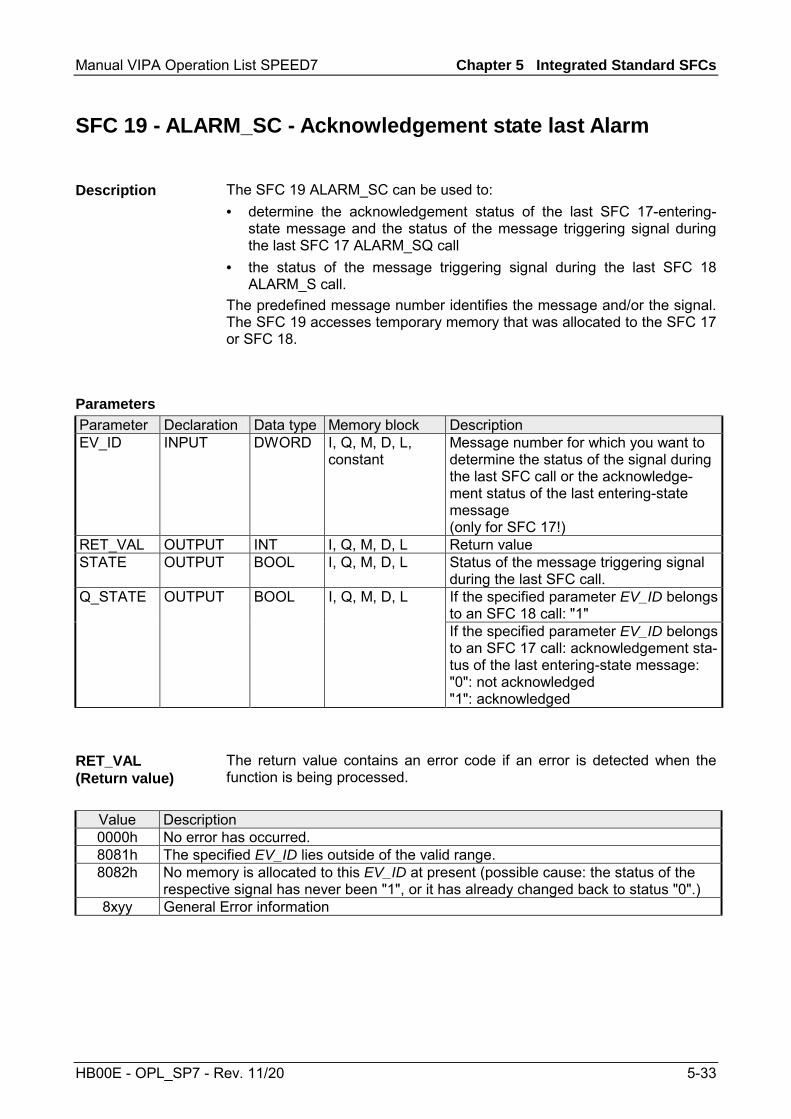
Manual VIPA Operation List SPEED7 Chapter 5 Integrated Standard SFCs
HB00E - OPL_SP7 - Rev. 11/20 5-33
SFC 19 - ALARM_SC - Acknowledgement state last Alarm
The SFC 19 ALARM_SC can be used to: • determine the acknowledgement status of the last SFC 17-entering-
state message and the status of the message triggering signal during the last SFC 17 ALARM_SQ call
• the status of the message triggering signal during the last SFC 18 ALARM_S call.
The predefined message number identifies the message and/or the signal. The SFC 19 accesses temporary memory that was allocated to the SFC 17 or SFC 18.
Parameter Declaration Data type Memory block Description EV_ID INPUT DWORD I, Q, M, D, L,
constant Message number for which you want to determine the status of the signal during the last SFC call or the acknowledge-ment status of the last entering-state message (only for SFC 17!)
RET_VAL OUTPUT INT I, Q, M, D, L Return value STATE OUTPUT BOOL I, Q, M, D, L Status of the message triggering signal
during the last SFC call. Q_STATE OUTPUT BOOL I, Q, M, D, L If the specified parameter EV_ID belongs
to an SFC 18 call: "1" If the specified parameter EV_ID belongs
to an SFC 17 call: acknowledgement sta-tus of the last entering-state message: "0": not acknowledged "1": acknowledged
The return value contains an error code if an error is detected when the function is being processed.
Value Description 0000h No error has occurred. 8081h The specified EV_ID lies outside of the valid range. 8082h No memory is allocated to this EV_ID at present (possible cause: the status of the
respective signal has never been "1", or it has already changed back to status "0".) 8xyy General Error information
Description
Parameters
RET_VAL (Return value)
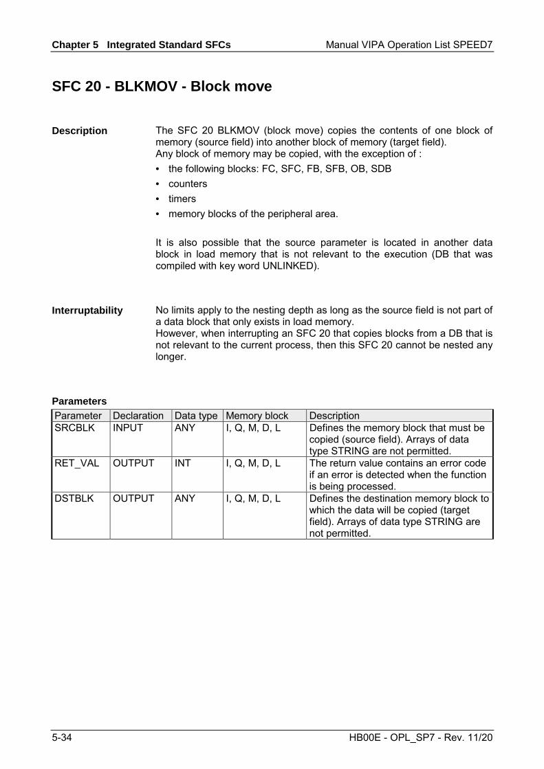
Chapter 5 Integrated Standard SFCs Manual VIPA Operation List SPEED7
5-34 HB00E - OPL_SP7 - Rev. 11/20
SFC 20 - BLKMOV - Block move
The SFC 20 BLKMOV (block move) copies the contents of one block of memory (source field) into another block of memory (target field). Any block of memory may be copied, with the exception of : • the following blocks: FC, SFC, FB, SFB, OB, SDB • counters • timers • memory blocks of the peripheral area. It is also possible that the source parameter is located in another data block in load memory that is not relevant to the execution (DB that was compiled with key word UNLINKED).
No limits apply to the nesting depth as long as the source field is not part of a data block that only exists in load memory. However, when interrupting an SFC 20 that copies blocks from a DB that is not relevant to the current process, then this SFC 20 cannot be nested any longer.
Parameter Declaration Data type Memory block Description SRCBLK INPUT ANY I, Q, M, D, L Defines the memory block that must be
copied (source field). Arrays of data type STRING are not permitted.
RET_VAL OUTPUT INT I, Q, M, D, L The return value contains an error code if an error is detected when the function is being processed.
DSTBLK OUTPUT ANY I, Q, M, D, L Defines the destination memory block to which the data will be copied (target field). Arrays of data type STRING are not permitted.
Description
Interruptability
Parameters
Manual VIPA Operation List SPEED7 Chapter 5 Integrated Standard SFCs
HB00E - OPL_SP7 - Rev. 11/20 5-35
Note! Source and target field must not overlap. If the specified target field is larger than the source filed then only the amount of data located in the source field will be copied. When the specified target field should, however, be smaller than the source filed, then only the amount of data that the target field can accommodate will be copied. If the type of the ANY-pointer (source or target) is BOOL, then the specified length must be divisible by 8, otherwise the SFC cannot be executed. If the type of the ANY-pointer is STRING, then the specified length must be equal to 1.
The return value contains an error code if an error is detected when the function is being processed.
Value Description 0000h No error 8091h The maximum nesting depth was exceeded
RET_VAL (Return value)
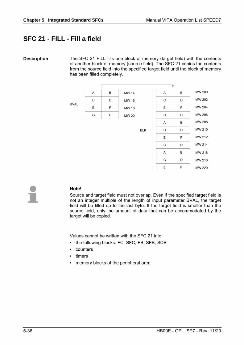
Chapter 5 Integrated Standard SFCs Manual VIPA Operation List SPEED7
5-36 HB00E - OPL_SP7 - Rev. 11/20
SFC 21 - FILL - Fill a field
The SFC 21 FILL fills one block of memory (target field) with the contents of another block of memory (source field). The SFC 21 copies the contents from the source field into the specified target field until the block of memory has been filled completely.
A
C
E
G
B
D
F
H
A
C
E
G
B
D
F
H
A
C
E
G
B
D
F
H
A
C
E
B
D
F
MW 14
MW 16
MW 18
MW 20
MW 200
MW 202
MW 204
MW 206
MW 208
MW 210
MW 212
MW 214
MW 216
MW 218
MW 220
BVAL
BLK
Note! Source and target field must not overlap. Even if the specified target field is not an integer multiple of the length of input parameter BVAL, the target field will be filled up to the last byte. If the target field is smaller than the source field, only the amount of data that can be accommodated by the target will be copied.
Values cannot be written with the SFC 21 into: • the following blocks: FC, SFC, FB, SFB, SDB • counters • timers • memory blocks of the peripheral area
Description

Manual VIPA Operation List SPEED7 Chapter 5 Integrated Standard SFCs
HB00E - OPL_SP7 - Rev. 11/20 5-37
Parameter Declaration Data type Memory block Description BVAL INPUT ANY I, Q, M, D, L Contains the value or the description of
the source field that should be copied into the target field. Arrays of the data type STRING are not permitted.
RET_VAL OUTPUT INT I, Q, M, D, L The return value contains an error code if an error is detected when the function is being processed.
BLK OUTPUT ANY I, Q, M, D, L Contains the description of the target field that must be filled. Arrays of the data type STRING are not permitted.
Pay attention to the following when the input parameter consists of a structure: the length of a structure is always aligned with an even number of bytes. This means, that if you should declare a structure with an uneven number of bytes, the structure will require one additional byte in memory. Example: The structure is declared as follows: STRUKTUR_7_BYTE: STRUCT BYTE_1_2 : WORD BYTE_3_4 : WORD BYTE_5_6 : WORD BYTE_7: BYTE END_STRUCT Structure "STRUKTUR_7_BYTE" requires 8bytes of memory.
The return value contains an error code if an error is detected when the function is being processed. The SFC 21 only returns general error information. No specific error information is available.
Parameters
Parameter is a structure
RET_VAL (Return value)

Chapter 5 Integrated Standard SFCs Manual VIPA Operation List SPEED7
5-38 HB00E - OPL_SP7 - Rev. 11/20
SFC 22 - CREAT_DB - Create a data block
The SFC 22 CREAT_DB (create data block) allows the application program to create a data block that does not contain any values. A data block is created that has a number in the specified range and with a specific size. The number assigned to the DB will always be the lowest number in the specified range. To create a DB with specific number you must assigned the same number to the upper and the lower limit of the range. If the application program already contains DBs then the respective numbers cannot be assigned any longer. The length of the DB must be an even number.
The SFC 22 may be interrupted by OBs with a higher priority. If a call is issued to an SFC 22 from an OB with a higher priority, then the call is rejected with error code 8091h.
Parameter Declaration Data type Memory block Description LOW_LIMIT INPUT WORD I, Q, M, D, L,
constant The lower limit is the lowest number in the range of numbers that you may assign to your data block.
UP_LIMIT INPUT WORD I, Q, M, D, L, constant
The upper limit is the highest number in the range of numbers that you may assign to your data block.
COUNT INPUT WORD I, Q, M, D, L, constant
The counter defines the number of data bytes that you wish to reserve for your data block. Here you must specify an even number of bytes (maximum 65534).
RET_VAL OUTPUT INT I, Q, M, D, L The return value contains an error code if an error is detected when the function is being processed.
DB_NUMBER OUTPUT WORD I, Q, M, D, L The data block number is the number of the data block that was created. When an error occurs (bit 15 of RET_VAL was set) a value of 0 is entered into DB_NUMBFC.
Description
Interruptability
Parameters

Manual VIPA Operation List SPEED7 Chapter 5 Integrated Standard SFCs
HB00E - OPL_SP7 - Rev. 11/20 5-39
The return value contains an error code if an error is detected when the function is being processed.
Value Description 0000h no error 8091h You issued a nested call to the SFC 22. 8092h The function "Create a DB" cannot be executed at present because
• the function "Compress application memory" is active 80A1h Error in the number of the DB:
• the number is 0 • the number exceeds the CPU-specific number of DBs • lower limit > upper limit
80A2h Error in the length of the DB: • the length is 0 • the length was specified as an uneven number • the length is larger than permitted by the CPU
80B1h No DB-number available 80B2h Insufficient memory available 80B3h Insufficient contiguous memory available (compress the memory!).
RET_VAL (Return value)

Chapter 5 Integrated Standard SFCs Manual VIPA Operation List SPEED7
5-40 HB00E - OPL_SP7 - Rev. 11/20
SFC 23 - DEL_DB - Deleting a data block
The SFC 23 DEL_DB (delete data block) deletes a data block in application memory and if necessary from the load memory of the CPU. The specified DB must not be open on the current level or on a level with a lower priority, i.e. it must not have been entered into one of the two DB-registers and also not into B-stack. Otherwise the CPU will change to STOP mode when the call to the SFC 23 is issued. The following table indicates when a DB may be deleted by means of the SFC 23.
When the DB ... then SFC 23 ... was created by means of a call to SFC 22 "CREAT_DB", can be used to delete it. was not created with the key word UNLINKED, can be used to delete it.
The SFC 23 may be interrupted by OBs with a higher priority. When another call is issued to the SFC the second call is rejected and RET_VAL is set to error code 8091h.
Parameter Declaration Data type Memory block Description DB_NUMBER INPUT WORD I, Q, M, D, L,
constant Number of the DB that must be deleted.
RET_VAL OUTPUT INT I, Q, M, D, L The return value contains an error code if an error is detected when the function is being processed.
The return value contains an error code if an error is detected when the function is being processed.
Value Description 0000h no error 8091h The maximum nesting depth of the respective CPU for nested calls to SFC 23
has been exceeded. 8092h The function "Delete a DB" cannot be executed at present because
• the function "Compress application memory" is active • you are copying the DB to be deleted from the CPU to an offline project
80A1h Error in input parameter DB_NUMBER: • has a value of 0 • exceeds the maximum DB number that is possible on the CPU that is
being used
80B1h A DB with the specified number does not exist on the CPU 80B2h A DB with the specified number was created with the key word UNLINKED 80B3h The DB is located on the flash memory card
Description
Interruptability
Parameters
RET_VAL (Return value)

Manual VIPA Operation List SPEED7 Chapter 5 Integrated Standard SFCs
HB00E - OPL_SP7 - Rev. 11/20 5-41
SFC 24 - TEST_DB - Test data block
The SFC 24 TEST_DB (test data block) returns information about a data block that is located in the application memory of the CPU. The SFC determines the number of data bytes and tests whether the selected DB is write protected.
Parameter Declaration Data type Memory block Description DB_NUMBER INPUT WORD I, Q, M, D, L,
constant Number of the DB that must be tested.
RET_VAL OUTPUT INT I, Q, M, D, L The return value contains an error code if an error is detected when the function is being processed.
DB_LENGTH OUTPUT WORD I, Q, M, D, L The number of data bytes that are contained in the selected DB.
WRITE_PROT OUTPUT BOOL I, Q, M, D, L Information about the write protection code of the selected DB (1 = write protected).
The return value contains an error code if an error is detected when the function is being processed.
Value Description 0000h no error 80A1h Error in input parameter DB_NUMBER:
the selected actual parameter • has a value of 0 • exceeds the maximum DB number that is possible on the CPU that is being
used
80B1h A DB with the specified number does not exist on the CPU. 80B2h A DB with the specified number was created with the key word UNLINKED.
Description
Parameters
RET_VAL (Return value)

Chapter 5 Integrated Standard SFCs Manual VIPA Operation List SPEED7
5-42 HB00E - OPL_SP7 - Rev. 11/20
SFC 25 - COMPRESS - Compressing the User Memory
Gaps can occur in the load memory and in the work memory if data blocks are deleted and reloaded several times. These gaps reduce the effective memory area.
With SFC 25 COMPRESS, you start compression of the RAM section of both the load memory and the work memory. The compression function is the same as when started externally in the RUN mode (mode selector setting). If compression was started externally and is still active (via Module Status Information), the SFC 25 call will result in an error message.
Parameter Declaration Data type Memory block Description RET_VAL OUTPUT INT E, A, M, D, L Error information BUSY OUTPUT BOOL E, A, M, D, L Indicates whether the compression
function started by an SFC 25 call is still active. (1 means active.)
DONE OUTPUT BOOL E, A, M, D, L Indicates whether the compression function started by SFC 25 was completed successfully. (1 means completed successfully.)
If SFC 25 COMPRESS is called once, the compression function is started. Call SFC 25 cyclically. First evaluate the parameter RET_VAL after every call. Provided that its value is 0, the parameters BUSY and DONE can be evaluated. If BUSY = 1 and DONE = 0, this indicates that the compression function is still active. When BUSY changes to value 0 and DONE to the value 1, this indicates that the compression function was completed successfully. If SFC 25 is called again afterwards, the compression function is started again.
Gaps in Memory
Description
Checking the Compression Function

Manual VIPA Operation List SPEED7 Chapter 5 Integrated Standard SFCs
HB00E - OPL_SP7 - Rev. 11/20 5-43
SFC 28 ... 31 - Time-of-day interrupt
The following conditions must be satisfied before a time-of-day interrupt OB 10 may be called: • The time-of-day interrupt OB must have been configured by hardware
configuration or by means of the SFC 28 (SET_TINT) in the user program.
• The time-of-day interrupt OB must have been activated by hardware configuration or by means of the SFC 30 (ACT_TINT) in the user program.
• The time-of-day interrupt OB must not have been de-selected. • The time-of-day interrupt OB must exist in the CPU. • When the SFC 30 is used to set the time-of-day interrupt by a single call
to the function the respective start date and time must not have expired when the function is initiated; the periodic execution initiates the time-of-day interrupt OB when the specified period has expired (start time + multiple of the period).
The system function are used as follows • Set: SFC 28 • Cancel: SFC 29 • Activate: SFC 30 • Query: SFC 31
The SFC 28 SET_TINT (set time-of-day interrupt) defines the start date and time for the time-of-day interrupt - organization modules. The start time ignores any seconds and milliseconds that may have been specified, these are set to 0.
Parameter Declaration Data type Memory block Description OB_NR INPUT INT I, Q, M, D, L,
constant Number of the OB, that is started at a time SDT + multiple of PERIOD (OB10, OB11).
SDT INPUT DT D, L Start date and start time PERIOD INPUT WORD I, Q, M, D, L,
constant Period from the start of SDT: 0000h = single 0201h = at minute intervals 0401h = hourly 1001h = daily 1201h = weekly 1401h = monthly 1801h = annually 2001h = at the end of a month
RET_VAL OUTPUT INT I, Q, M, D, L The return value contains an error code if an error is detected when the function is being processed.
Conditions
SFCs 28 ... 31
SFC 28 -SET_TINT
Parameters

Chapter 5 Integrated Standard SFCs Manual VIPA Operation List SPEED7
5-44 HB00E - OPL_SP7 - Rev. 11/20
The return value contains an error code if an error is detected when the function is being processed.
Value Description 0000h No error has occurred. 8090h OB_NR parameter error 8091h SDT parameter error 8092h PERIOD parameter error 80A1h The stated date/time has already expired.
The SFC 29 CAN_TINT (cancel time-of-day interrupt) deletes the start date and time of the specified time-of-day interrupt - organization block
Parameter Declaration Data type Memory block Description OB_NR INPUT INT I, Q, M, D, L,
constant Number of the OB, in which the start date and time will be canceled (OB 10, OB 11).
RET_VAL OUTPUT INT I, Q, M, D, L
The return value contains an error code if an error is detected when the function is being processed.
Value Description 0000h No error has occurred. 8090h OB_NR parameter error 80A0h No start date/time was defined for the respective time-of-day interrupt OB.
RET_VAL (Return value)
SFC 29 -CAN_TINT - Cancel time-of-day interrupt
Parameters
RET_VAL (Return value)
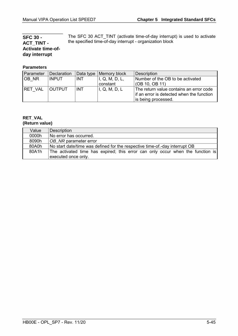
Manual VIPA Operation List SPEED7 Chapter 5 Integrated Standard SFCs
HB00E - OPL_SP7 - Rev. 11/20 5-45
The SFC 30 ACT_TINT (activate time-of-day interrupt) is used to activate the specified time-of-day interrupt - organization block
Parameter Declaration Data type Memory block Description OB_NR INPUT INT I, Q, M, D, L,
constant Number of the OB to be activated (OB 10, OB 11)
RET_VAL OUTPUT INT I, Q, M, D, L
The return value contains an error code if an error is detected when the function is being processed.
Value Description 0000h No error has occurred. 8090h OB_NR parameter error 80A0h No start date/time was defined for the respective time-of.-day interrupt OB 80A1h The activated time has expired; this error can only occur when the function is
executed once only.
SFC 30 - ACT_TINT - Activate time-of-day interrupt
Parameters
RET_VAL (Return value)
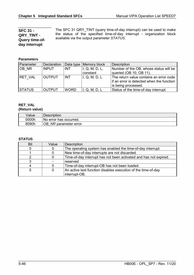
Chapter 5 Integrated Standard SFCs Manual VIPA Operation List SPEED7
5-46 HB00E - OPL_SP7 - Rev. 11/20
The SFC 31 QRY_TINT (query time-of-day interrupt) can be used to make the status of the specified time-of-day interrupt - organization block available via the output parameter STATUS.
Parameter Declaration Data type Memory block Description OB_NR INPUT INT I, Q, M, D, L,
constant Number of the OB, whose status will be queried (OB 10, OB 11).
RET_VAL OUTPUT INT I, Q, M, D, L The return value contains an error code if an error is detected when the function is being processed.
STATUS OUTPUT WORD I, Q, M, D, L Status of the time-of-day interrupt.
Value Description 0000h No error has occurred. 8090h OB_NR parameter error
Bit Value Description 0 0 The operating system has enabled the time-of-day interrupt. 1 0 New time-of-day interrupts are not discarded. 2 0 Time-of-day interrupt has not been activated and has not expired. 3 - reserved 4 0 Time-of-day interrupt-OB has not been loaded. 5 0 An active test function disables execution of the time-of-day
interrupt-OB.
SFC 31 - QRY_TINT - Query time-of-day interrupt
Parameters
RET_VAL (Return value)
STATUS

Manual VIPA Operation List SPEED7 Chapter 5 Integrated Standard SFCs
HB00E - OPL_SP7 - Rev. 11/20 5-47
SFC 32 - SRT_DINT - Start time-delay interrupt
The SFC 32 SRT_DINT (start time-delay interrupt) can be used to start a time-delay interrupt that issues a call to a time-delay interrupt OB after the pre-configured delay time (parameter DTIME) has expired. Parameter SIGN specifies a user-defined code that identifies the start of the time-delay interrupt. While the function is being executed the values of DTIME and SIGN appear in the startup event information of the specified OB. The following conditions must be satisfied before a time-delay interrupt OB may be called: • the time-delay interrupt OB must have been started (using the SFC 32) • the time-delay interrupt OB must not have been de-selected. • the time-delay interrupt OB must exist in the CPU.
Parameter Declaration Data type Memory block Description OB_NR INPUT INT I, Q, M, D, L,
constant Number of the OB, that is started after the time delay (OB 20, OB 21).
DTIME INPUT TIME I, Q, M, D, L, constant
The delay time (1 ... 60 000ms)
SIGN INPUT WORD I, Q, M, D, L, constant
Code that is inserted into the startup event information of the OB when a call is issued to the time-delay inter-rupt.
RET_VAL OUTPUT INT I, Q, M, D, L The return value contains an error code if an error is detected when the function is being processed.
The time from the call to the SFC 32 and the start of the time-delay interrupt OB may be less than the configured time by no more than one millisecond, provided that no interrupt events have occurred that delay the call.
Value Description 0000h No error has occurred. 8090h OB_NR parameter error 8091h DTIME parameter error
Description
Conditions
Parameters
Accuracy
RET_VAL (Return value)

Chapter 5 Integrated Standard SFCs Manual VIPA Operation List SPEED7
5-48 HB00E - OPL_SP7 - Rev. 11/20
SFC 33 - CAN_DINT - Cancel time-delay interrupt
The SFC 33 CAN_DINT (cancel time-delay interrupt) cancels a time-delay interrupt that has already been started. The call to the respective time-delay interrupt OB will not be issued.
The following conditions must be satisfied before a time-delay interrupt OB may be called: • The time-delay interrupt OB must have been started (using the SFC 32). • The time-delay interrupt OB must not have been de-selected. • The time-delay interrupt OB must exist in the CPU.
Parameter Declaration Data type Memory block Description OB_NR INPUT INT I, Q, M, D, L,
constant Number of the OB, that must be cancelled (OB 20, OB 21).
RET_VAL OUTPUT INT I, Q, M, D, L The return value contains an error code if an error is detected when the function is being processed.
Value Description 0000h No error has occurred. 8090h OB_NR parameter error 80A0h Time-delay interrupt has not been started.
Description
Conditions
Parameters
RET_VAL (Return value)

Manual VIPA Operation List SPEED7 Chapter 5 Integrated Standard SFCs
HB00E - OPL_SP7 - Rev. 11/20 5-49
SFC 34 - QRY_DINT - Query time-delay interrupt
The SFC 34 QRY_DINT (query time-delay interrupt) can be used to make the status of the specified time-delay interrupt available via the output parameter STATUS.
The following conditions must be satisfied before a time-delay interrupt OB may be called: • The time-delay interrupt OB must have been started (using the SFC 32). • The time-delay interrupt OB must not have been de-selected. • The time-delay interrupt OB must exist in the CPU.
Parameter Declaration Data type Memory block Description OB_NR INPUT INT I, Q, M, D, L,
Constant Number of the OB, that must be cancelled (OB 20, OB 21)
RET_VAL OUTPUT INT I, Q, M, D, L The return value contains an error code if an error is detected when the function is being processed.
STATUS OUTPUT WORD I, Q, M, D, L Status of the time-delay interrupt
Value Description 0000h No error has occurred. 8090h OB_NR parameter error
Bit Value Description 0 0 The operating system has enabled the time-delay interrupt. 1 0 New time-delay interrupts are not discarded. 2 0 Time-delay interrupt has not been activated and has not expired. 3 - - 4 0 Time-delay interrupt-OB has not been loaded. 5 0 An active test function disables execution of the time-delay interrupt-
OB.
Description
Conditions
Parameters
RET_VAL (Return value)
STATUS

Chapter 5 Integrated Standard SFCs Manual VIPA Operation List SPEED7
5-50 HB00E - OPL_SP7 - Rev. 11/20
SFC 36 - MSK_FLT - Mask synchronous errors
The SFC 36 MSK_FLT (mask synchronous faults) is used to control the reaction of the CPU to synchronous faults by masking the respective synchronous faults. The call to the SFC 36 masks the synchronous faults of the current priority class. If you set individual bits of the synchronous fault mask in the input parameters to "1" other bits that have previously been set will remain at "1". This result in new synchronous fault masks that can be retrieved via the output parameters. Masked synchronous faults are entered into an error register and do not issue a call to an OB. The error register is read by means of the SFC 38 READ_ERR.
Parameter Declaration Data type Memory block Description PRGFLT_SET_MASK INPUT DWORD I, Q, M, D, L,
constant Programming faults that must be masked out
ACCFLT_SET_MASK INPUT DWORD I, Q, M, D, L, constant
Access faults that must be masked out
RET_VAL OUTPUT INT I, Q, M, D, L The return value contains an error code if an error is detected when the function is being processed.
PRGFLT_MASKED OUTPUT DWORD I, Q, M, D, L Masked programming faults ACCFLT_MASKED OUTPUT DWORD I, Q, M, D, L Masked access errors
Value Description 0000h None of the faults has previously been masked. 0001h One or more of the faults has already been masked, however, the other
faults will still be masked out.
Description
Parameters
RET_VAL (Return value)

Manual VIPA Operation List SPEED7 Chapter 5 Integrated Standard SFCs
HB00E - OPL_SP7 - Rev. 11/20 5-51
SFC 37 - DMSK_FLT - Unmask synchronous errors
The SFC 37 DMSK_FLT (unmask synchronous faults) unmasks any masked synchronous faults. A call to the SFC 37 unmasks the synchronous faults of the current priority class. The respective bits in the fault mask of the input parameters are set to "1". This results in new fault masks that you can read via the output parameters. Queried entries are deleted from in the error register.
Parameter Declaration Data type Memory block Description PRGFLT_RESET_MASK INPUT DWORD I, Q, M, D, L,
constant Programming faults that must be unmasked
ACCFLT_RESET_MASK INPUT DWORD I, Q, M, D, L, constant
Access faults that must be unmasked
RET_VAL OUTPUT INT I, Q, M, D, L The return value contains an error code if an error is detected when the function is being processed.
PRGFLT_MASKED OUTPUT DWORD I, Q, M, D, L Masked programming faults
ACCFLT_MASKED OUTPUT DWORD I, Q, M, D, L Masked access errors
Value Description 0000h All the specified faults have been unmasked. 0001h One or more of the faults was not masked, however, the other faults
will still be unmasked.
Description
Parameters
RET_VAL (Return value)

Chapter 5 Integrated Standard SFCs Manual VIPA Operation List SPEED7
5-52 HB00E - OPL_SP7 - Rev. 11/20
SFC 38 - READ_ERR - Read error register
The SFC 38 READ_ERR (read error registers) reads the contents of the error register. The structure of the error register is identical to the structure of the programming fault and access fault masks that were defined as input parameters by means of the SFC 36 and 37. When you issue a call to the SFC 38 the specified entries are read and simultaneously deleted from the error register. The input parameters define which synchronous faults will be queried in the error register. The function indicates the masked synchronous faults of the current priority class that have occurred once or more than once. When a bit is set it signifies that the respective masked synchronous fault has occurred.
Parameter Declaration Data type Memory block Description PRGFLT_QUERY INPUT DWORD I, Q, M, D, L,
constant Query programming faults
ACCFLT_QUERY INPUT DWORD I, Q, M, D, L, constant
Query access faults
RET_VAL OUTPUT INT I, Q, M, D, L The return value contains an error code if an error is detected when the function is being processed.
PRGFLT_ESR OUTPUT DWORD I, Q, M, D, L Programming faults that have occurred
ACCFLT_ESR OUTPUT DWORD I, Q, M, D, L Access faults that have occurred
Value Description 0000h All the specified faults have been masked. 0001h One or more of the faults that have occurred was not masked.
Description
Parameters
RET_VAL (Return value)

Manual VIPA Operation List SPEED7 Chapter 5 Integrated Standard SFCs
HB00E - OPL_SP7 - Rev. 11/20 5-53
SFC 39 - DIS_IRT - Disabling interrupts
With the SFC 39 DIS_IRT (disable interrupt) you disable the processing of new interrupts and asynchronous errors. This means that if an interrupt occurs, the operating system of the CPU reacts as follows: • if neither calls an interrupt OB asynchronous error OB, • nor triggers the normal reaction if an interrupt OB or asynchronous error
OB is not programmed. If you disable interrupts and asynchronous errors, this remains in effect for all priority classes. The effects of SFC 39 can only be canceled again by calling the SFC 40 or by a restart. Whether the operating system writes interrupts and asynchronous errors to the diagnostic buffer when they occur depends on the input parameter setting you select for MODE.
Note! Remember that when you program the use of the SFC 39, all interrupts that occur are lost.
Parameter Declaration Data type Memory block Description MODE INPUT BYTE I, Q, M, D, L,
constant Specifies which interrupts and asynchronous errors are disabled.
OB_NR INPUT INT I, Q, M, D, L, constant
OB number
RET_VAL OUTPUT INT I, Q, M, D, L If an error occurs while the function is active, the return value contains an error code.
Description
Parameters
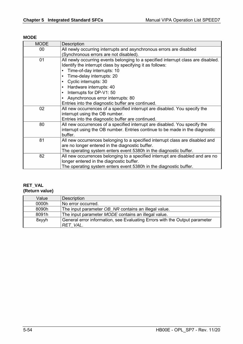
Chapter 5 Integrated Standard SFCs Manual VIPA Operation List SPEED7
5-54 HB00E - OPL_SP7 - Rev. 11/20
MODE Description
00 All newly occurring interrupts and asynchronous errors are disabled (Synchronous errors are not disabled).
01 All newly occurring events belonging to a specified interrupt class are disabled. Identify the interrupt class by specifying it as follows: • Time-of-day interrupts: 10 • Time-delay interrupts: 20 • Cyclic interrupts: 30 • Hardware interrupts: 40 • Interrupts for DP-V1: 50 • Asynchronous error interrupts: 80 Entries into the diagnostic buffer are continued.
02 All new occurrences of a specified interrupt are disabled. You specify the interrupt using the OB number. Entries into the diagnostic buffer are continued.
80 All new occurrences of a specified interrupt are disabled. You specify the interrupt using the OB number. Entries continue to be made in the diagnostic buffer.
81 All new occurrences belonging to a specified interrupt class are disabled and are no longer entered in the diagnostic buffer. The operating system enters event 5380h in the diagnostic buffer.
82 All new occurrences belonging to a specified interrupt are disabled and are no longer entered in the diagnostic buffer. The operating system enters event 5380h in the diagnostic buffer.
Value Description 0000h No error occurred. 8090h The input parameter OB_NR contains an illegal value. 8091h The input parameter MODE contains an illegal value. 8xyyh General error information, see Evaluating Errors with the Output parameter
RET_VAL.
MODE
RET_VAL (Return value)

Manual VIPA Operation List SPEED7 Chapter 5 Integrated Standard SFCs
HB00E - OPL_SP7 - Rev. 11/20 5-55
SFC 40 - EN_IRT - Enabling interrupts
With the SFC 40 EN_IRT (enable interrupt) you enable the processing of new interrupts and asynchronous errors that you previously disabled with the SFC 39. This means that if an interrupt event occurs, the operating system of the CPU reacts in one of the follows ways: • it calls an interrupt OB or asynchronous error OB,
or • it triggers the standard reaction if an interrupt OB or asynchronous error
OB is not programmed.
Parameter Declaration Data type Memory block Description MODE INPUT BYTE I, Q, M, D, L,
constant Specifies which interrupts and asynchronous errors will be enabled.
OB_NR INPUT INT I, Q, M, D, L, constant
OB number
RET_VAL OUTPUT INT I, Q, M, D, L If an error occurs while the function is active, the return value contains an error code.
MODE Description 00 All newly occurring interrupts and asynchronous errors are enabled. 01 All newly occurring events belonging to a specified interrupt class are enabled.
Identify the interrupt class by specifying it as follows: • Time-of-day interrupts: 10 • Time-delay interrupts: 20 • Cyclic interrupts: 30 • Hardware interrupts: 40 • Interrupts for DP-V1: 50 • Asynchronous error interrupts: 80
02 All newly occurring events of a specified interrupt are enabled. You specify the interrupt using the OB number.
Value Description 0000h No error occurred. 8090h The input parameter OB_NR contains an illegal value. 8091h The input parameter MODE contains an illegal value. 8xyyh General error information, see Evaluating Errors with the Output parameter
RET_VAL.
Description
Parameters
MODE
RET_VAL (Return value)

Chapter 5 Integrated Standard SFCs Manual VIPA Operation List SPEED7
5-56 HB00E - OPL_SP7 - Rev. 11/20
SFC 41 - DIS_AIRT - Delaying interrupts
The SFC 41 DIS_AIRT (disable alarm interrupts) disables processing of interrupt OBs and asynchronous fault OBs with a priority that is higher than the priority of the current OB. You can issue multiple calls to the SFC 41. The operating system will count the number of calls to the SFC 41. Processing of interrupt OBs is disabled until you issue an SFC 42 EN_AIRT to enable all interrupt OBs and asynchronous fault OBs that were disabled by means of SFC 41 or until processing of the current OB has been completed. Any queued interrupt or asynchronous fault interrupts will be processed as soon as you enable processing by means of the SFC 42 EN_AIRT or when processing of the current OB has been completed.
Parameter Declaration Data type Memory area Description RET_VAL OUTPUT INT I, Q, M, D, L Number of disable calls
(= number of calls to the SFC 41)
When the SFC has been completed the return value RET_VAL indicates the number of disables, i.e. the number of calls to the SFC 41 (processing of all alarm interrupts is only enabled again when RET_VAL = 0).
Description
Parameters
RET_VAL (Return value)

Manual VIPA Operation List SPEED7 Chapter 5 Integrated Standard SFCs
HB00E - OPL_SP7 - Rev. 11/20 5-57
SFC 42 - EN_AIRT - Enabling delayed interrupts
The SFC 42 EN_AIRT (enable alarm interrupts) enables processing of high priority interrupt OBs and asynchronous fault OBs. Every disabled interrupt must be re-enabled by means of the SFC 42. If you have disabled 5 different interrupts by means of 5 SFC 41 calls you must re-enable every alarm interrupt by issuing 5 individual SFC 42 calls.
Parameter Declaration Data type Memory block Description RET_VAL OUTPUT INT I, Q, M, D, L Number of disabled interrupts when the
SFC 42 has been completed or the error code when an error has occurred while the function was being processed.
When the SFC has been completed the return value RET_VAL indicates the number of disables, i.e. the number of calls to the SFC 41 (processing of all alarm interrupts is only enabled again when RET_VAL = 0).
Value Description 8080h The function was started in spite of the fact that the alarm interrupt had already been
enabled.
SFC 43 - RE_TRIGR - Retrigger the watchdog
The SFC 43 RE_TRIGR (retrigger watchdog) restarts the watchdog timer of the CPU. The SFC 43 has neither parameters nor return values.
Description
Parameters
RET_VAL (Return value)
Description
Parameter and return values

Chapter 5 Integrated Standard SFCs Manual VIPA Operation List SPEED7
5-58 HB00E - OPL_SP7 - Rev. 11/20
SFC 44 - REPL_VAL - Replace value to AKKU1
The SFC 44 REPL_VAL (replace value) transfers a value into AKKU1 of the program level that cause the fault. A call to the SFC 44 can only be issued from synchronous fault OBs (OB 121, OB 122). Application example for the SFC 44: When an input module malfunctions so that it is not possible to read any values from the respective module then OB 122 will be started after each attempt to access the module. The SFC 44 REPL_VAL can be used in OB 122 to transfer a suitable replacement value into AKKU1 of the program level that was interrupted. The program will be continued with this replacement value. The information required to select a replacement value (e.g. the module where the failure occurred, the respective address) are available from the local variables of OB 122.
Parameter Declaration Data type Memory block Description VAL INPUT DWORD I, Q, M, D, L,
constant Replacement value
RET_VAL OUTPUT INT I, Q, M, D, L The return value contains an error code if an error is detected when the function is being processed.
Value Description 0000h No error has occurred. A replacement value has been entered. 8080h The call to the SFC 44 was not issued from a synchronous fault
OB (OB 121, OB 122).
SFC 46 - STP - STOP the CPU
The SFC 46 STP changes the operation mode of the CPU to STOP. The SFC 46 has neither parameters nor return values.
Description
Parameters
RET_VAL (Return value)
Description
Parameter and return values

Manual VIPA Operation List SPEED7 Chapter 5 Integrated Standard SFCs
HB00E - OPL_SP7 - Rev. 11/20 5-59
SFC 47 - WAIT - Delay the application program
The SFC 47 WAIT can be used to program time delays or wait times from 1 up to 32767µs in your application program.
The SFC 47 may be interrupted by high priority OBs.
Note! Delay times that were programmed by means of the SFC 47 are minimum times that may be extended by the execution time of the nested priority classes as well as the load on the system!
Parameter Declaration Data type Memory block Description WT INPUT INT I, Q, M, D, L,
constant Parameter WT contains the delay time in µs.
The SFC 47 does not return specific error codes.
Description
Interruptability
Parameters
Error information
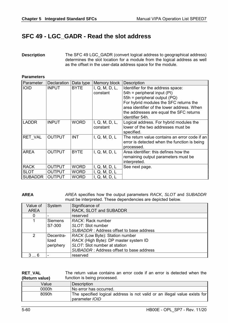
Chapter 5 Integrated Standard SFCs Manual VIPA Operation List SPEED7
5-60 HB00E - OPL_SP7 - Rev. 11/20
SFC 49 - LGC_GADR - Read the slot address
The SFC 49 LGC_GADR (convert logical address to geographical address) determines the slot location for a module from the logical address as well as the offset in the user-data address space for the module.
Parameter Declaration Data type Memory block Description IOID INPUT BYTE I, Q, M, D, L,
constant Identifier for the address space: 54h = peripheral input (PI) 55h = peripheral output (PQ) For hybrid modules the SFC returns the area identifier of the lower address. When the addresses are equal the SFC returns identifier 54h.
LADDR INPUT WORD I, Q, M, D, L, constant
Logical address. For hybrid modules the lower of the two addresses must be specified.
RET_VAL OUTPUT INT I, Q, M, D, L The return value contains an error code if an error is detected when the function is being processed.
AREA OUTPUT BYTE I, Q, M, D, L Area identifier: this defines how the remaining output parameters must be interpreted.
RACK OUTPUT WORD I, Q, M, D, L SLOT OUTPUT WORD I, Q, M, D, L SUBADDR OUTPUT WORD I, Q, M, D, L
See next page.
AREA specifies how the output parameters RACK, SLOT and SUBADDR must be interpreted. These dependencies are depicted below.
Value of AREA
System Significance of RACK, SLOT and SUBADDR
0 - reserved 1 Siemens
S7-300 RACK: Rack number SLOT: Slot number SUBADDR : Address offset to base address
2 Decentra-lized periphery
RACK (Low Byte): Station number RACK (High Byte): DP master system ID SLOT: Slot number at station SUBADDR : Address offset to base address
3 ... 6 - reserved
The return value contains an error code if an error is detected when the function is being processed.
Value Description 0000h No error has occurred. 8090h The specified logical address is not valid or an illegal value exists for
parameter IOID
Description
Parameters
AREA
RET_VAL (Return value)

Manual VIPA Operation List SPEED7 Chapter 5 Integrated Standard SFCs
HB00E - OPL_SP7 - Rev. 11/20 5-61
SFC 50 - RD_LGADR - Read all logical addresses of a module
The SFC 50 RD_LGADR (read module logical addresses) determines all the stipulated logical addresses of a module starting with a logical address of the respective module. You must have previously configured the relationship between the logical addresses and the modules. The logical addresses that were determined are entered in ascending order into the field PEADDR or into field PAADDR.
Parameter Declaration Data type Memory block Description IOID INPUT BYTE I, Q, M, D, L,
constant Area identification: 54h = peripheral input (PI) 55h = peripheral output (PQ)
LADDR INPUT WORD I, Q, M, D, L, constant
A logical address
RET_VAL OUTPUT INT I, Q, M, D, L The return value contains an error code if an error is detected when the function is being processed.
PEADDR OUTPUT ANY I, Q, M, D, L Field for the PI-addresses, field elements must be of data type WORD.
PECOUNT OUTPUT INT I, Q, M, D, L Number of returned PI addresses PAADDR OUTPUT ANY I, Q, M, D, L Field for PQ addresses, field elements
must be of data type WORD. PACOUNT OUTPUT INT I, Q, M, D, L Number of returned PQ addresses
The return value contains an error code if an error is detected when the function is being processed.
Value Description 0000h No error has occurred. 8090h The specified logical address is not valid or illegal value for parameter IOID. 80A0 h Error in output parameter PEADDR: data type of the field elements is not WORD. 80A1h Error in output parameter PAADDR: data type of the field elements is not WORD. 80A2h Error in output parameter PEADDR: the specified field could not accommodate all
the logical addresses. 80A3h Error in output parameter PAADDR: the specified field could not accommodate all
the logical addresses.
Description
Parameters
RET_VAL (Return value)

Chapter 5 Integrated Standard SFCs Manual VIPA Operation List SPEED7
5-62 HB00E - OPL_SP7 - Rev. 11/20
SFC 51 - RDSYSST - Read system status list SSL
With the SFC 51 RDSYSST (read system status) a partial list respectively an extract of a partial list of the SSL (system status list) may be requested. Here with the parameters SSL_ID and INDEX the objects to be read are defined. The INDEX is not always necessary. It is used to define an object within a partial list. By setting REQ the query is started. As soon as BUSY = 0 is reported, the data are located in the target area DR. Information about the SSL may be found in Chapter "System status list SSL".
Parameter Declaration Data type Memory block Description REQ INPUT BOOL I, Q, M, D, L,
constant REQ = 1: start processing
SSL_ID INPUT WORD I, Q, M, D, L, constant
SSL-ID of the partial list or the partial list extract
INDEX INPUT WORD I, Q, M, D, L, constant
Type or number of an object in a partial list
RET_VAL OUTPUT INT I, Q, M, D, L The return value contains an error code if an error is detected when the function is being processed
BUSY OUTPUT BOOL I, Q, M, D, L BUSY = 1: read operation has not been completed
SSL_HEADER OUTPUT STRUCT D, L WORD structure with 2 types: LENGTHDR: length record set N_DR: number of existing related records (for access to partial list header information) or number of records transmitted in DR.
DR OUTPUT ANY I, Q, M, D, L Target area for the SSL partial list or the extraction of the partial list that was read: If you have only read the SSL partial list header info of a SSL partial list, you may not evaluate DR, but only SSL_HEADER. Otherwise the product of LENGTHDR and N_DR shows the number of bytes stored in DR.
Description
Parameters
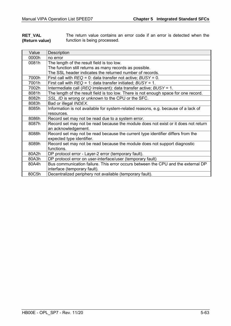
Manual VIPA Operation List SPEED7 Chapter 5 Integrated Standard SFCs
HB00E - OPL_SP7 - Rev. 11/20 5-63
The return value contains an error code if an error is detected when the function is being processed.
Value Description 0000h no error 0081h The length of the result field is too low.
The function still returns as many records as possible. The SSL header indicates the returned number of records.
7000h First call with REQ = 0: data transfer not active; BUSY = 0. 7001h First call with REQ = 1: data transfer initiated; BUSY = 1. 7002h Intermediate call (REQ irrelevant): data transfer active; BUSY = 1. 8081h The length of the result field is too low. There is not enough space for one record. 8082h SSL_ID is wrong or unknown to the CPU or the SFC. 8083h Bad or illegal INDEX. 8085h Information is not available for system-related reasons, e.g. because of a lack of
resources. 8086h Record set may not be read due to a system error. 8087h Record set may not be read because the module does not exist or it does not return
an acknowledgement. 8088h Record set may not be read because the current type identifier differs from the
expected type identifier. 8089h Record set may not be read because the module does not support diagnostic
functions. 80A2h DP protocol error - Layer-2 error (temporary fault). 80A3h DP protocol error on user-interface/user (temporary fault) 80A4h Bus communication failure. This error occurs between the CPU and the external DP
interface (temporary fault). 80C5h Decentralized periphery not available (temporary fault).
RET_VAL (Return value)

Chapter 5 Integrated Standard SFCs Manual VIPA Operation List SPEED7
5-64 HB00E - OPL_SP7 - Rev. 11/20
SFC 52 - WR_USMSG - Write user entry into diagnostic buffer
The SFC 52 WR_USMSG (write user element in diagnosis buffer) writes a used defined diagnostic element into the diagnostic buffer.
To determine whether it is possible to send user defined diagnostic messages you must issue a call to SFC 51 "RDSYSST" with parameters SZL_ID = 0132h and INDEX = 0005h. Sending of user defined diagnostic messages is possible if the fourth word of the returned record set is set to "1". If it should contain a value of "0", sending is not possible.
The diagnostic message can only be entered into the send buffer if this is not full. At a maximum of 50 entries can be stored in the send buffer. If the send buffer is full • the diagnostic event is still entered into the diagnostic buffer • the respective error message (8092h) is entered into parameter
RET_VAL.
When a user defined diagnostic message must be sent and no partner has registered, then • the diagnostic event is still entered into the diagnostic buffer. • the respective error message (0091h or 8091h) is entered into
parameter RET_VAL.
Description
Send diagnostic message
Send buffer full
Partner not registered
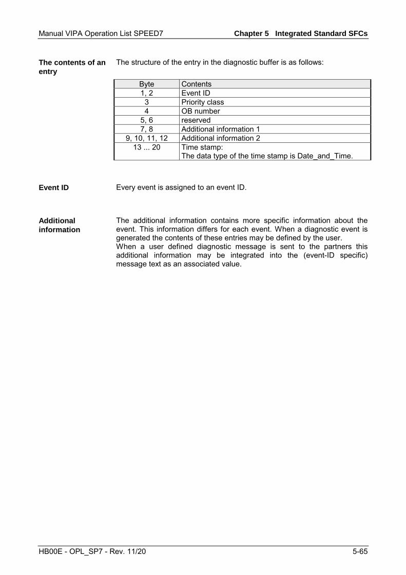
Manual VIPA Operation List SPEED7 Chapter 5 Integrated Standard SFCs
HB00E - OPL_SP7 - Rev. 11/20 5-65
The structure of the entry in the diagnostic buffer is as follows:
Byte Contents 1, 2 Event ID
3 Priority class 4 OB number
5, 6 reserved 7, 8 Additional information 1
9, 10, 11, 12 Additional information 2 13 ... 20 Time stamp:
The data type of the time stamp is Date_and_Time.
Every event is assigned to an event ID.
The additional information contains more specific information about the event. This information differs for each event. When a diagnostic event is generated the contents of these entries may be defined by the user. When a user defined diagnostic message is sent to the partners this additional information may be integrated into the (event-ID specific) message text as an associated value.
The contents of an entry
Event ID
Additional information

Chapter 5 Integrated Standard SFCs Manual VIPA Operation List SPEED7
5-66 HB00E - OPL_SP7 - Rev. 11/20
Parameter Declaration Data type Memory block Description SEND INPUT BOOL I, Q, M, D, L,
constant Enable sending of user defined diagnostic messages to all registered partners
EVENTN INPUT WORD I, Q, M, D, L, constant
Event-ID. The user assigns the event-ID. This is not preset by the message server.
INFO1 INPUT ANY I, Q, M, D, L Additional information, length 1 word INFO2 INPUT ANY I, Q, M, D, L Additional information, length 2 words RET_VAL OUTPUT INT I, Q, M, D, L The return value contains an error code
if an error is detected when the function is being processed.
When SEND is set to 1 the user defined diagnostic message is sent to all partners that have registered for this purpose. Sending is only initiated when one or more partners have registered and the send buffer is not full. Messages are sent asynchronously with respect to the application program.
The event ID of the user event is entered into EVENTN. Event IDs must be of the format 8xyzh , 9xyzh, Axyzh and Bxyzh. Here the IDs of format 8xyzh and 9xyzh refer to predefined events and IDs of format Axyzh and Bxyzh refer to user-defined events. An event being activated is indicated by x = 1, an event being deactivated by x = 0. For events of the class A and B, yz refers to the message number that was predefined in hexadecimal representation when the messages were configured.
INFO1 contains information with a length of one word. The following data types are valid: • WORD • INT • ARRAY [0...1] OF CHAR INFO1 can be integrated as associated value into the message text, i.e. to add current information to the message.
Parameters
SEND
EVENTN
INFO1

Manual VIPA Operation List SPEED7 Chapter 5 Integrated Standard SFCs
HB00E - OPL_SP7 - Rev. 11/20 5-67
INFO2 contains information with a length of two words. The following data types are valid: • DWORD • DINT • REAL • TIME • ARRAY [0...3] OF CHAR INFO2 can be integrated as associated value into the message text, i.e. to add current information to the message.
The return value contains an error code if an error is detected when the function is being processed.
Value Description 0000h no error 0091h No partner registered (the diagnostic event has been entered into the diagnostic
buffer) 8083h Data type INFO1 not valid 8084h Data type INFO2 not valid 8085h EVENTN not valid 8086h Length of INFO1 not valid 8087h Length of INFO2 not valid 8091h Error message identical to error code 0091h 8092h Send operation currently not possible, send buffer full
(the diagnostic event has been entered into the diagnostic buffer)
INFO2
RET_VAL (Return value)

Chapter 5 Integrated Standard SFCs Manual VIPA Operation List SPEED7
5-68 HB00E - OPL_SP7 - Rev. 11/20
SFC 54 - RD_DPARM - Read predefined parameter
The SFC 54 RD_DPARM (read defined parameter) reads the record with number RECNUM of the selected module from the respective SDB1xy. Parameter RECORD defines the target area where the record will be saved
Parameter Declaration Data type Memory block Description IOID INPUT BYTE I, Q, M, D, L,
constant Identifier for the address space: 54h = peripheral input (PI) 55h = peripheral output (PQ) For hybrid modules the SFC returns the area identifier of the lower address. When the addresses are equal the SFC returns identifier 54h.
LADDR INPUT WORD I, Q, M, D, L, constant
Logical address. For hybrid modules the lower of the two addresses must be specified.
RECNUM INPUT BYTE I, Q, M, D, L, constant
record number (valid range: 0 ... 240)
RET_VAL OUTPUT INT I, Q, M, D, L The return value contains an error code if an error is detected when the function is being processed. Additionally: the length of the record that was read in bytes, provided the size of the record fits into the target area and that no communication errors have occurred.
RECORD OUTPUT ANY I, Q, M, D, L Target area for the record that was read. Only data type BYTE is valid.
Description
Parameters
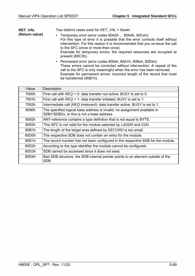
Manual VIPA Operation List SPEED7 Chapter 5 Integrated Standard SFCs
HB00E - OPL_SP7 - Rev. 11/20 5-69
Two distinct cases exist for RET_VAL = 8xxxh: • Temporary error (error codes 80A2h ... 80A4h, 80Cxh):
For this type of error it is possible that the error corrects itself without intervention. For this reason it is recommended that you re-issue the call to the SFC (once or more than once). Example for temporary errors: the required resources are occupied at present (80C3h).
• Permanent error (error codes 809xh, 80A1h, 80Bxh, 80Dxh): These errors cannot be corrected without intervention. A repeat of the call to the SFC is only meaningful when the error has been removed. Example for permanent errors: incorrect length of the record that must be transferred (80B1h).
Value Description 7000h First call with REQ = 0: data transfer not active; BUSY is set to 0. 7001h First call with REQ = 1: data transfer initiated; BUSY is set to 1. 7002h Intermediate call (REQ irrelevant): data transfer active; BUSY is set to 1. 8090h The specified logical base address is invalid: no assignment available in
SDB1/SDB2x, or this is not a base address. 8092h ANY-reference contains a type definition that is not equal to BYTE. 8093h This SFC is not valid for the module selected by LADDR and IOID. 80B1h The length of the target area defined by RECORD is too small. 80D0h The respective SDB does not contain an entry for the module. 80D1h The record number has not been configured in the respective SDB for the module. 80D2h According to the type identifier the module cannot be configured. 80D3h SDB cannot be accessed since it does not exist. 80D4h Bad SDB structure: the SDB internal pointer points to an element outside of the
SDB.
RET_VAL (Return value)
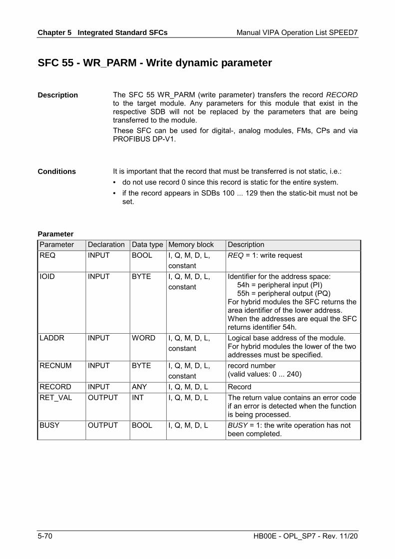
Chapter 5 Integrated Standard SFCs Manual VIPA Operation List SPEED7
5-70 HB00E - OPL_SP7 - Rev. 11/20
SFC 55 - WR_PARM - Write dynamic parameter
The SFC 55 WR_PARM (write parameter) transfers the record RECORD to the target module. Any parameters for this module that exist in the respective SDB will not be replaced by the parameters that are being transferred to the module. These SFC can be used for digital-, analog modules, FMs, CPs and via PROFIBUS DP-V1.
It is important that the record that must be transferred is not static, i.e.: • do not use record 0 since this record is static for the entire system. • if the record appears in SDBs 100 ... 129 then the static-bit must not be
set.
Parameter Declaration Data type Memory block Description REQ INPUT BOOL I, Q, M, D, L,
constant REQ = 1: write request
IOID INPUT BYTE I, Q, M, D, L, constant
Identifier for the address space: 54h = peripheral input (PI) 55h = peripheral output (PQ) For hybrid modules the SFC returns the area identifier of the lower address. When the addresses are equal the SFC returns identifier 54h.
LADDR INPUT WORD I, Q, M, D, L, constant
Logical base address of the module. For hybrid modules the lower of the two addresses must be specified.
RECNUM INPUT BYTE I, Q, M, D, L, constant
record number (valid values: 0 ... 240)
RECORD INPUT ANY I, Q, M, D, L Record RET_VAL OUTPUT INT I, Q, M, D, L The return value contains an error code
if an error is detected when the function is being processed.
BUSY OUTPUT BOOL I, Q, M, D, L BUSY = 1: the write operation has not been completed.
Description
Conditions
Parameter

Manual VIPA Operation List SPEED7 Chapter 5 Integrated Standard SFCs
HB00E - OPL_SP7 - Rev. 11/20 5-71
With the first call to the SFC the data that must be transferred is read from the parameter RECORD. However, if the transfer of the record should require more than one call duration, the contents of the parameter RECORD is no longer valid for subsequent calls to the SFC (of the same job).
Two distinct cases exist for RET_VAL = 8xxxh: • Temporary error (error codes 80A2h ... 80A4h, 80Cxh):
For this type of error it is possible that the error corrects itself without intervention. For this reason it is recommended that you re-issue the call to the SFC (once or more than once). Example for temporary errors: the required resources are occupied at present (80C3h).
• Permanent error (error codes 809xh, 80A1h, 80Bxh, 80Dxh): These errors cannot be corrected without intervention. A repeat of the call to the SFC is only meaningful when the error has been removed. Example for permanent errors: incorrect length of the record that must be transferred (80B1h).
Value Description 7000h First call with REQ = 0: data transfer not active; BUSY is set to 0. 7001h First call with REQ = 1: data transfer initiated; BUSY is set to 1. 7002h Intermediate call (REQ irrelevant): data transfer active; BUSY is set to 1. 8090h The specified logical base address is invalid: no assignment available in
SDB1/SDB2x, or this is not a base address. 8092h ANY-reference contains a type definition that is not equal to BYTE. 8093h This SFC is not valid for the module selected by LADDR and IOID. 80A1h Negative acknowledgement when the record is being transferred to the module
(module was removed during the transfer or module failed) 80A2h DP protocol fault in layer 2, possible hardware-/ interface fault in the DP slave 80A3h DP protocol fault for user Interface/user 80A4h Communication failure (this fault occurs between the CPU and the external DP
interface) 80B0h SFC cannot be used with this type of module or the module does not recognize the
record. continued ...
RECORD
RET_VAL (Return value)

Chapter 5 Integrated Standard SFCs Manual VIPA Operation List SPEED7
5-72 HB00E - OPL_SP7 - Rev. 11/20
... continue Value Description 80B1h The length of the target area determined by RECORD is too small. 80B2h The slot that was configured has not been populated. 80B3h The actual type of module is not equal to the required type of module in SDB1 80C1h The module has not yet completed processing of the data of the preceding write
operation for the same record. 80C2h The module is currently processing the maximum number of jobs for a CPU. 80C3h Required resources (memory, etc.) are currently occupied. 80C4h Communication error: 80C5h Decentralized periphery not available. 80C6h The transfer of records was aborted due to a priority class abort (warm start or
background) 80D0h The respective SDB does not contain an entry for the module. 80D1h The record number was not configured in the respective SDB. 80D2h Based on the type identifier the module cannot be configured. 80D3h The SDB cannot be accessed since it does not exist. 80D4h Bad SDB structure: the SDB internal pointer points to an element outside of the
SDB. 80D5h The record is not static.

Manual VIPA Operation List SPEED7 Chapter 5 Integrated Standard SFCs
HB00E - OPL_SP7 - Rev. 11/20 5-73
SFC 56 - WR_DPARM - Write default parameter
The SFC 56 WR_DPARM (write default parameter) transfers the record RECNUM from the respective SDB to the target module, irrespective of whether the specific record is static or dynamic. These SFC can be used for digital-, analog modules, FMs, CPs and via PROFIBUS DP-V1.
Parameter Declaration Data type Memory block Description REQ INPUT BOOL I, Q, M, D, L,
constant REQ = 1: write request
IOID INPUT BYTE I, Q, M, D, L, constant
Identifier for the address space: 54h = peripheral input (PI) 55h = peripheral output (PQ) For hybrid modules the SFC returns the area identifier of the lower address. When the addresses are equal the SFC returns identifier 54h.
LADDR INPUT WORD I, Q, M, D, L, constant
Logical base address of the module. For hybrid modules the lower of the two addresses must be specified.
RECNUM INPUT BYTE I, Q, M, D, L, constant
Record number (valid values: 0 ... 240)
RET_VAL OUTPUT INT I, Q, M, D, L The return value contains an error code if an error is detected when the function is being processed.
BUSY OUTPUT BOOL I, Q, M, D, L BUSY = 1: the write operation has not been completed.
Description
Parameters

Chapter 5 Integrated Standard SFCs Manual VIPA Operation List SPEED7
5-74 HB00E - OPL_SP7 - Rev. 11/20
Two distinct cases exist for RET_VAL = 8xxxh: • Temporary error (error codes 80A2h ... 80A4h, 80Cxh):
For this type of error it is possible that the error corrects itself without intervention. For this reason it is recommended that you re-issue the call to the SFC (once or more than once). Example for temporary errors: the required resources are occupied at present (80C3h).
• Permanent error (error codes 809xh, 80A1h, 80Bxh, 80Dxh): These errors cannot be corrected without intervention. A repeat of the call to the SFC is only meaningful when the error has been removed. Example for permanent errors: incorrect length of the record that must be transferred (80B1h).
Value Description 7000h First call with REQ = 0: data transfer not active; BUSY is set to 0. 7001h First call with REQ = 1: data transfer initiated; BUSY is set to 1. 7002h Intermediate call (REQ irrelevant): data transfer active; BUSY is set to 1. 8090h The specified logical base address is invalid: no assignment available in
SDB1/SDB2x, or this is not a base address. 8093h This SFC is not valid for the module selected by means of LADDR and IOID. 80A1h Negative acknowledgement when the record is being transferred to the module
(module was removed during the transfer or module failed) 80A2h DP protocol fault in layer 2, possible hardware-/ interface fault in the DP slave 80A3h DP protocol fault for user Interface/user 80A4h Communication failure
(this fault occurs between the CPU and the external DP interface). 80B0h SFC cannot be used with this type of module or the module does not recognize the
record. 80B1h The length of the target area determined by RECORD is too small. 80B2h The slot that was configured has not been populated. 80B3h The actual type of module is not equal to the required type of module in SDB1. 80C1h The module has not yet completed processing of the data of the preceding write
operation for the same record. 80C2h The module is currently processing the maximum number of jobs for a CPU. 80C3h Required resources (memory, etc.) are currently occupied. 80C4h Communication error 80C5h Decentralized periphery not available. 80C6h The transfer of records was aborted due to a priority class abort
(warm start or background). 80D0h The respective SDB does not contain an entry for the module. 80D1h The record number was not configured in the respective SDB. 80D2h Based on the type identifier the module cannot be configured. 80D3h The SDB cannot be accessed since it does not exist. 80D4h Bad SDB structure: the SDB internal pointer points to an element outside of the
SDB.
RET_VAL (Return value)
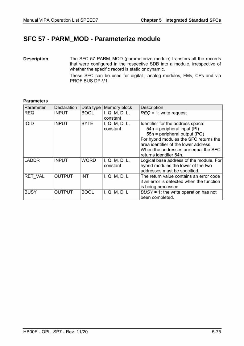
Manual VIPA Operation List SPEED7 Chapter 5 Integrated Standard SFCs
HB00E - OPL_SP7 - Rev. 11/20 5-75
SFC 57 - PARM_MOD - Parameterize module
The SFC 57 PARM_MOD (parameterize module) transfers all the records that were configured in the respective SDB into a module, irrespective of whether the specific record is static or dynamic. These SFC can be used for digital-, analog modules, FMs, CPs and via PROFIBUS DP-V1.
Parameter Declaration Data type Memory block Description REQ INPUT BOOL I, Q, M, D, L,
constant REQ = 1: write request
IOID INPUT BYTE I, Q, M, D, L, constant
Identifier for the address space: 54h = peripheral input (PI) 55h = peripheral output (PQ) For hybrid modules the SFC returns the area identifier of the lower address. When the addresses are equal the SFC returns identifier 54h.
LADDR INPUT WORD I, Q, M, D, L, constant
Logical base address of the module. For hybrid modules the lower of the two addresses must be specified.
RET_VAL OUTPUT INT I, Q, M, D, L The return value contains an error code if an error is detected when the function is being processed.
BUSY OUTPUT BOOL I, Q, M, D, L BUSY = 1: the write operation has not been completed.
Description
Parameters

Chapter 5 Integrated Standard SFCs Manual VIPA Operation List SPEED7
5-76 HB00E - OPL_SP7 - Rev. 11/20
Two distinct cases exist for RET_VAL = 8xxxh: • Temporary error (error codes 80A2h ... 80A4h, 80Cxh):
For this type of error it is possible that the error corrects itself without intervention. For this reason it is recommended that you re-issue the call to the SFC (once or more than once). Example for temporary errors: the required resources are occupied at present (80C3h).
• Permanent error (error codes 809xh, 80A1h, 80Bxh, 80Dxh): These errors cannot be corrected without intervention. A repeat of the call to the SFC is only meaningful when the error has been removed. Example for permanent errors: incorrect length of the record that must be transferred (80B1h).
Value Description 7000h First call with REQ = 0: data transfer not active; BUSY is set to 0. 7001h First call with REQ = 1: data transfer initiated; BUSY is set to 1. 7002h Intermediate call (REQ irrelevant): data transfer active; BUSY is set to 1. 8090h The specified logical base address is invalid: no assignment available in
SDB1/SDB2x, or this is not a base address. 8093h This SFC is not valid for the module selected by means of LADDR and IOID. 80A1h Negative acknowledgement when the record is being transferred to the module
(module was removed during the transfer or module failed) 80A2h DP protocol fault in layer 2, possible hardware-/ interface fault in the DP slave 80A3h DP protocol fault for user Interface/user 80A4h Communication failure (this fault occurs between the CPU and the external DP
interface) 80B0h SFC cannot be used with this type of module or the module does not recognize the
record. 80B1h The length of the target area determined by RECORD is too small. 80B2h The slot that was configured has not been populated. 80B3h The actual type of module is not equal to the required type of module in SDB1 80C1h The module has not yet completed processing of the data of the preceding write
operation for the same record. 80C2h The module is currently processing the maximum number of jobs for a CPU. 80C3h Required resources (memory, etc.) are currently occupied. 80C4h Communication error 80C5h Decentralized periphery not available. 80C6h The transfer of records was aborted due to a priority class abort
(warm start or background) 80D0h The respective SDB does not contain an entry for the module. 80D1h The record number was not configured in the respective SDB. 80D2h Based on the type identifier the module cannot be configured. 80D3h The SDB cannot be accessed since it does not exist. 80D4h Bad SDB structure: the SDB internal pointer points to an element outside of the
SDB.
RET_VAL (Return value)

Manual VIPA Operation List SPEED7 Chapter 5 Integrated Standard SFCs
HB00E - OPL_SP7 - Rev. 11/20 5-77
SFC 58 - WR_REC - Write record
The SFC 58 WR_REC (write record) transfers the record RECORD into the selected module. The write operation is started when input parameter REQ is set to 1 when the call to the SFC 58 is issued. Output parameter BUSY returns a value of 0 if the write operation was executed immediately. BUSY is set to 1 if the write operation could not be completed. These SFC can be used for digital-, analog modules, FMs, CPs and via PROFIBUS DP-V1. System dependent this block cannot be interrupted!
Parameter Declaration Data type Memory block Description REQ INPUT BOOL I, Q, M, D, L,
constant REQ = 1: write request
IOID INPUT BYTE I, Q, M, D, L, constant
Identifier for the address space: 54h = peripheral input (PI) 55h = peripheral output (PQ) For hybrid modules the SFC returns the area identifier of the lower address. When the addresses are equal the SFC returns identifier 54h.
LADDR INPUT WORD I, Q, M, D, L, constant
Logical base address of the module. For hybrid modules the lower of the two addresses must be specified.
RECNUM INPUT BYTE I, Q, M, D, L, constant
Record number (valid range: 2 ... 240)
RECORD INPUT ANY I, Q, M, D, L Record. Only data type BYTE is valid. RET_VAL OUTPUT INT I, Q, M, D, L The return value contains an error code
if an error is detected when the function is being processed.
BUSY OUTPUT BOOL I, Q, M, D, L BUSY = 1: the write operation has not been completed.
Description
Parameter

Chapter 5 Integrated Standard SFCs Manual VIPA Operation List SPEED7
5-78 HB00E - OPL_SP7 - Rev. 11/20
With the first call to the SFC the data that must be transferred is read from the parameter RECORD. However, if the transfer of the record should require more than one call duration, the contents of the parameter RECORD is no longer valid for subsequent calls to the SFC (of the same job).
Two distinct cases exist for RET_VAL = 8xxxh: • Temporary error (error codes 80A2h ... 80A4h, 80Cxh):
For this type of error it is possible that the error corrects itself without intervention. For this reason it is recommended that you re-issue the call to the SFC (once or more than once). Example for temporary errors: the required resources are occupied at present (80C3h).
• Permanent error (error codes 809xh, 80A0, 80A1h, 80Bxh): These errors cannot be corrected without intervention. A repeat of the call to the SFC is only meaningful when the error has been removed. Example for permanent errors: incorrect length of the record that must be transferred (80B1h).
Value Description 7000h First call with REQ = 0: data transfer not active; BUSY is set to 0. 7001h First call with REQ = 1: data transfer initiated; BUSY is set to 1. 7002h Intermediate call (REQ irrelevant): data transfer active; BUSY is set to 1. 8090h The specified logical base address is invalid: no assignment available in
SDB1/SDB2x, or this is not a base address. 8092h ANY-reference contains a type definition that is not equal to BYTE. 8093h This SFC is not valid for the module selected by LADDR and IOID. 80A1h Negative acknowledgement when the record is being transferred to the module
(module was removed during the transfer or module failed) 80A2h DP protocol fault in layer 2, possible hardware-/ interface fault in the DP slave 80A3h DP protocol fault for user Interface/user 80A4h Communication failure
(this fault occurs between the CPU and the external DP interface) continued ...
RECORD
RET_VAL (Return value)
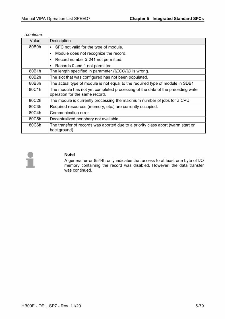
Manual VIPA Operation List SPEED7 Chapter 5 Integrated Standard SFCs
HB00E - OPL_SP7 - Rev. 11/20 5-79
... continue Value Description 80B0h • SFC not valid for the type of module.
• Module does not recognize the record. • Record number ≥ 241 not permitted. • Records 0 and 1 not permitted.
80B1h The length specified in parameter RECORD is wrong. 80B2h The slot that was configured has not been populated. 80B3h The actual type of module is not equal to the required type of module in SDB1 80C1h The module has not yet completed processing of the data of the preceding write
operation for the same record. 80C2h The module is currently processing the maximum number of jobs for a CPU. 80C3h Required resources (memory, etc.) are currently occupied. 80C4h Communication error 80C5h Decentralized periphery not available. 80C6h The transfer of records was aborted due to a priority class abort (warm start or
background)
Note! A general error 8544h only indicates that access to at least one byte of I/O memory containing the record was disabled. However, the data transfer was continued.

Chapter 5 Integrated Standard SFCs Manual VIPA Operation List SPEED7
5-80 HB00E - OPL_SP7 - Rev. 11/20
SFC 59 - RD_REC - Read record
The SFC 59 RD_REC (read record) reads the record with the number RECNUM from the selected module. These SFC can be used for digital-, analog modules, FMs, CPs and via PROFIBUS DP-V1. The read operation is started when input parameter REQ is set to 1 when the call to SFC 59 is issued. Output parameter BUSY returns a value of 0 if the read operation was executed immediately. BUSY is set to 1 if the read operation could not be completed. Parameter RECORD determines the target area where the record is saved when it has been transferred successfully. System dependent this block cannot be interrupted!
Parameter Declaration Data type Memory block Description REQ INPUT BOOL I, Q, M, D, L,
constant REQ = 1: read request
IOID INPUT BYTE I, Q, M, D, L, constant
Identifier for the address space: 54h = peripheral input (PI) 55h = peripheral output (PQ) For hybrid modules the SFC returns the area identifier of the lower address. When the addresses are equal the SFC returns identifier 54h.
LADDR INPUT WORD I, Q, M, D, L, constant
Logical base address of the module. For hybrid modules the lower of the two addresses must be specified.
RECNUM INPUT BYTE I, Q, M, D, L, constant
Record number (valid range: 0 ... 240)
RET_VAL OUTPUT INT I, Q, M, D, L The return value contains an error code if an error is detected when the function is being processed. Additionally: the length of the actual record that was read, in bytes (range: +1 ... +240), provided that the target area is greater than the transferred record and that no communication errors have occurred.
BUSY OUTPUT BOOL I, Q, M, D, L BUSY = 1: the write operation has not been completed.
continued ...
Description
Parameter

Manual VIPA Operation List SPEED7 Chapter 5 Integrated Standard SFCs
HB00E - OPL_SP7 - Rev. 11/20 5-81
... continue Parameter Declaration Data type Memory block Description RECORD OUTPUT ANY I, Q, M, D, L Target area for the record that was
read. When SFC 59 is processed in asynchronous mode you must ensure that the actual parameters of RECORD have the same length information for all calls. Only data type BYTE is permitted.
To ensure that an entire record is read you must select a target area with a length of 241bytes. In this case the value in RET_VAL indicates the actual length of the data that was transferred successfully.
RET_VAL contains an error code when an error occurs while the function was being processed. When the transfer was successful RET_VAL contains: • a value of 0 if the entire target area was filled with data from the
selected record (the record may, however, be incomplete). • the length of the record that was transferred, in bytes (valid range:
1 ... 240), provided that the target area is greater than the transferred record.
Error information Two distinct cases exist for RET_VAL = 8xxxh: • Temporary error (error codes 80A2h ... 80A4h, 80Cxh):
For this type of error it is possible that the error corrects itself without intervention. For this reason it is recommended that you re-issue the call to the SFC (once or more than once). Example for temporary errors: the required resources are occupied at present (80C3h).
• Permanent error (error codes 809xh, 80A0h, 80A1h, 80Bxh): These errors cannot be corrected without intervention. A repeat of the call to the SFC is only meaningful when the error has been removed. Example for permanent errors: incorrect length of the record that must be transferred (80B1h).
Suitable choice of RECORD
RET_VAL (Return value)

Chapter 5 Integrated Standard SFCs Manual VIPA Operation List SPEED7
5-82 HB00E - OPL_SP7 - Rev. 11/20
Error information Value Description 7000h First call with REQ = 0: data transfer not active; BUSY is set to 0. 7001h First call with REQ = 1: data transfer initiated; BUSY is set to 1. 7002h Intermediate call (REQ irrelevant): data transfer active; BUSY is set to 1. 8090h The specified logical base address is invalid: no assignment available in
SDB1/SDB2x, or this is not a base address. 8092h ANY-reference contains a type definition that is not equal to BYTE. 8093h This SFC is not valid for the module selected by LADDR and IOID. 80A0h Negative acknowledgement when reading from the module
(module was removed during the transfer or module failed) 80A2h DP protocol fault in layer 2, possible hardware-/ interface fault in the DP slave 80A3h DP protocol fault for user Interface/user 80A4h Communication failure (this fault occurs between the CPU and the external DP
interface) 80B0h • SFC not valid for the type of module.
• Module does not recognize the record. • Record number ≥ 241 not permitted.
80B1h The length specified in parameter RECORD is wrong. 80B2h The slot that was configured has not been populated. 80B3h The actual type of module is not equal to the required type of module in SDB1 80C0h The module has registered the record but this does not contain any read data as
yet. 80C1h The module has not yet completed processing of the data of the preceding write
operation for the same record. 80C2h The module is currently processing the maximum number of jobs for a CPU. 80C3h Required resources (memory, etc.) are currently occupied. 80C4h Communication error 80C5h Decentralized periphery not available. 80C6h The transfer of records was aborted due to a priority class abort (warm start or
background)
Note! A general error 8745h only indicates that access to at least one byte of I/O memory containing the record was disabled. However, the data was read successfully from the module and saved to the I/O memory block.

Manual VIPA Operation List SPEED7 Chapter 5 Integrated Standard SFCs
HB00E - OPL_SP7 - Rev. 11/20 5-83
SFC 64 - TIME_TCK - Read system time tick
The SFC 64 TIME_TCK (time tick) retrieves the system time tick from the CPU. This ma be used to assess the time that certain processes require calculating the difference between the values returned by two SFC 64 calls. The system time is a "time counter" that counts from 0 to a max. of 2147483647ms and that restarts from 0 when an overflow occurs. The timing intervals and the accuracy of the system time depend on the CPU. Only the operating modes of the CPU influence the system time.
Operating mode System time ... Restart RUN
... permanently updated.
STOP ... stopped to retain the last value. warm start ... continues from the value that was saved when STOP occurred. reboot ... is deleted and starts from "0".
Parameter Declaration Data type Memory block Description RET_VAL OUTPUT TIME I, Q, M, D, L Parameter RET_VAL contains the
system time that was retrieved, range from 0 ... 231 -1ms.
The SFC 64 does not return any error information.
Description
System time and operating modes
Parameters
RET_VAL (Return value)

Chapter 5 Integrated Standard SFCs Manual VIPA Operation List SPEED7
5-84 HB00E - OPL_SP7 - Rev. 11/20
SFC 65 - X_SEND - Send data
The SFC 65 X_SEND can be used to send data to an external communication partner outside the local station. The communication partner receives the data by means of the SFC 66 X_RCV. Input parameter REQ_ID is used to identify the transmit data. This code is transferred along with the transmit data and it can be analyzed by the communication partner to determine the origin of the data. The transfer is started when input parameter REQ is set to 1. The size of the transmit buffer that is defined by parameter SD (on the sending CPU) must be less than or equal to the size of the receive buffer (on the communication partner) that was defined by means of parameter RD. In addition, the data type of the transmit buffer and the receive buffer must be identical.
Parameter Declaration Data type Memory block Description REQ INPUT BOOL I, Q, M, D, L,
constant control parameter "request to activate", initiates the operation
CONT INPUT BOOL I, Q, M, D, L, constant
control parameter "continue", defines whether the connection to the communication partner is terminated or not when the operation has been completed
DEST_ID INPUT WORD I, Q, M, D, L, constant
Address parameter "destination ID". Contains the MPI-address of the communication partners.
REQ_ID INPUT DWORD I, Q, M, D, L, constant
Operation code identifying the data on the communication partner.
SD INPUT ANY I, Q, M, D Reference to the send buffer. The following data types are possible: BOOL, BYTE, CHAR, WORD, INT, DWORD, DINT, REAL, DATE, TOD, TIME, S5_TIME, DATE_AND_TIME as well as arrays of the respective data types, with the exception of BOOL.
RET_VAL OUTPUT INT I, Q, M, D, L The return value contains an error code if an error is detected when the function is being processed.
BUSY OUTPUT BOOL I, Q, M, D, L BUSY = 1: the send operation has not yet been completed. BUSY = 0: the send operation has been completed, or no send operation is active.
Description
Parameters

Manual VIPA Operation List SPEED7 Chapter 5 Integrated Standard SFCs
HB00E - OPL_SP7 - Rev. 11/20 5-85
Input parameter REQ_ID identifies the send data. Parameter REQ_ID is required by the receiver when • the sending CPU issues multiple calls to SFC 65 with different REQ_ID
parameters and the data is transferred to a single communication partner.
• more than one sending CPU are transferring data to a communication partner by means of the SFC 65.
Receive data can be saved into different memory blocks by analyzing the REQ_ID parameter. Data consistency Since send data is copied into an internal buffer of the operating system when the first call is issued to the SFC it is important to ensure that the send buffer is not modified before the first call has been completed successfully. Otherwise an inconsistency could occur in the transferred data. Any write-access to send data that occurs after the first call is issued does not affect the data consistency.
The return value contains an error code if an error is detected when the function is being processed. The "real error information" that is contained in the table "specific error information" a. o. may be classified as follows:
Value Description 809xh Error on the CPU where the SFC is being executed 80Axh Permanent communication error. 80Bxh Error on the communication partner. 80Cxh Temporary error.
REQ_ID
RET_VAL (Return value)

Chapter 5 Integrated Standard SFCs Manual VIPA Operation List SPEED7
5-86 HB00E - OPL_SP7 - Rev. 11/20
Specific error information: Value Description 0000h Processing completed without errors. 7000h First call with REQ = 0: no data transfer is active; BUSY is set to 0. 7001h First call with REQ = 1: data transfer initiated; BUSY is set to 1. 7002h Intermediate call (REQ irrelevant): data transfer active; BUSY is set to 1. 8090h The specified target address of the communication partners is not valid, e.g.
• bad IOID • bad base address exists • bad MPI-address (> 126)
8092h Error in SD or RD, e.g.: • illegal length for SD • SD = NIL is not permitted
8095h The block is already being processed on a priority class that has a lower priority. 80A0h Error in received acknowledgement. 80A1h Communication failures: SFC-call after an existing connection has been terminated.80B1h ANY-pointer error. The length of the data buffer that must be transferred is wrong. 80B4h ANY-pointer data type error, or ARRAY of the specified data type is not permitted. 80B5h Processing rejected because of an illegal operating mode. 80B6h The received acknowledgement contains an unknown error code. 80B8h The SFC 66 "X_RCV" of the communication partner rejected the data transfer
(RD = NIL). 80B9h The data block was identified by the communication partner (SFC 66 "X_RCV" was
called with EN_DT = 0) but it has not yet been accepted into the application program because the operating mode is STOP.
80BAh The answer of the communication partner does not fit into the communication telegram.
80C0h The specified connection is already occupied by another operation. 80C1h Lack of resources on the CPU where the SFC is being executed, e.g.:
• The module is already executing the maximum number of different send operations.
• Connection resources may be occupied, e.g. by a receive operation.
80C2h Temporary lack of resources for the communication partner, e.g.: • The communication partner is currently processing the maximum number of
operations. • The required resources (memory, etc.) are already occupied. • Not enough memory (initiate compression.)
80C3h Error when establishing a connection, e.g.: • The local station is connected to the MPI sub-net. • You have addressed the local station on the MPI sub-net. • The communication partner cannot be contacted any longer • Temporary lack of resources for the communication partner.

Manual VIPA Operation List SPEED7 Chapter 5 Integrated Standard SFCs
HB00E - OPL_SP7 - Rev. 11/20 5-87
SFC 66 - X_RCV - Receive data
The SFC 66 X_RCVS can be used to receive data, that was sent by means of SFC 65 X_SEND by one or more external communication partners. SFC 66 can determine whether the data that was sent is available at the current point in time. The operating system could have stored the respective data in an internal queue. If the data exists in the queue the oldest data block can be copied into the specified receive buffer.
Parameter Declaration Data type Memory block Description EN_DT INPUT BOOL I, Q, M, D, L,
constant Control parameter "enable data transfer". You can check whether one or more data blocks are available by setting this to 0. A value of 1 results in the oldest data block of the queue being copied into the memory block that was specified by means of RD.
RET_VAL OUTPUT INT I, Q, M, D, L The return value contains an error code if an error is detected when the function is being processed.
REQ_ID OUTPUT DWORD I, Q, M, D, L Operation code of the SFC 65 "X_SEND" whose send data is located uppermost in the queue, i.e. the oldest data in the queue. If the queue does not contain a data block REQ_ID is set to 0.
NDA OUTPUT BOOL I, Q, M, D, L Status parameter "new data arrived". NDA = 0: • The queue does not contain a data
block. NDA = 1: • The queue does contain one or more
data blocks. (call to the SFC 66 with EN_DT = 0).
• The oldest data block in the queue was copied into the application program. (call to the SFC 66 with EN_DT = 1).
continued ...
Description
Parameters
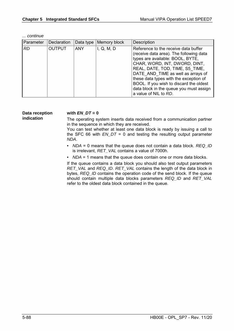
Chapter 5 Integrated Standard SFCs Manual VIPA Operation List SPEED7
5-88 HB00E - OPL_SP7 - Rev. 11/20
... continue Parameter Declaration Data type Memory block Description RD OUTPUT ANY I, Q, M, D Reference to the receive data buffer
(receive data area). The following data types are available: BOOL, BYTE, CHAR, WORD, INT, DWORD, DINT, REAL, DATE, TOD, TIME, S5_TIME, DATE_AND_TIME as well as arrays of these data types with the exception of BOOL. If you wish to discard the oldest data block in the queue you must assign a value of NIL to RD.
with EN_DT = 0 The operating system inserts data received from a communication partner in the sequence in which they are received. You can test whether at least one data block is ready by issuing a call to the SFC 66 with EN_DT = 0 and testing the resulting output parameter NDA. • NDA = 0 means that the queue does not contain a data block. REQ_ID
is irrelevant, RET_VAL contains a value of 7000h. • NDA = 1 means that the queue does contain one or more data blocks. If the queue contains a data block you should also test output parameters RET_VAL and REQ_ID. RET_VAL contains the length of the data block in bytes, REQ_ID contains the operation code of the send block. If the queue should contain multiple data blocks parameters REQ_ID and RET_VAL refer to the oldest data block contained in the queue.
Data reception indication
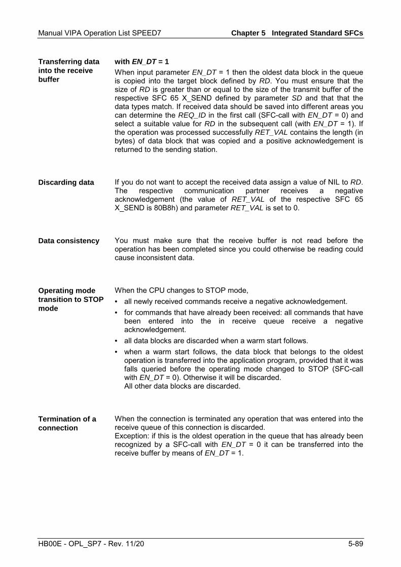
Manual VIPA Operation List SPEED7 Chapter 5 Integrated Standard SFCs
HB00E - OPL_SP7 - Rev. 11/20 5-89
with EN_DT = 1 When input parameter EN_DT = 1 then the oldest data block in the queue is copied into the target block defined by RD. You must ensure that the size of RD is greater than or equal to the size of the transmit buffer of the respective SFC 65 X_SEND defined by parameter SD and that that the data types match. If received data should be saved into different areas you can determine the REQ_ID in the first call (SFC-call with EN_DT = 0) and select a suitable value for RD in the subsequent call (with EN_DT = 1). If the operation was processed successfully RET_VAL contains the length (in bytes) of data block that was copied and a positive acknowledgement is returned to the sending station.
If you do not want to accept the received data assign a value of NIL to RD. The respective communication partner receives a negative acknowledgement (the value of RET_VAL of the respective SFC 65 X_SEND is 80B8h) and parameter RET_VAL is set to 0.
You must make sure that the receive buffer is not read before the operation has been completed since you could otherwise be reading could cause inconsistent data.
When the CPU changes to STOP mode, • all newly received commands receive a negative acknowledgement. • for commands that have already been received: all commands that have
been entered into the in receive queue receive a negative acknowledgement.
• all data blocks are discarded when a warm start follows. • when a warm start follows, the data block that belongs to the oldest
operation is transferred into the application program, provided that it was falls queried before the operating mode changed to STOP (SFC-call with EN_DT = 0). Otherwise it will be discarded. All other data blocks are discarded.
When the connection is terminated any operation that was entered into the receive queue of this connection is discarded. Exception: if this is the oldest operation in the queue that has already been recognized by a SFC-call with EN_DT = 0 it can be transferred into the receive buffer by means of EN_DT = 1.
Transferring data into the receive buffer
Discarding data
Data consistency
Operating mode transition to STOP mode
Termination of a connection

Chapter 5 Integrated Standard SFCs Manual VIPA Operation List SPEED7
5-90 HB00E - OPL_SP7 - Rev. 11/20
If no error has occurred, RET_VAL contains: • when EN_DT = 0/1 and NDA = 0: 7000h. In this case the queue does
not contain a data block. • when EN_DT = 0 and NDA = 1, RET_VAL contains the length (in bytes)
of the oldest data block that was entered into the queue as a positive number.
• when EN_DT = 1 and NDA = 1, RET_VAL contains the length (in bytes) of the data block that was copied into the receive buffer RD as a positive number.
Error information The "real error information" that is contained in the table "specific error information" a. o. may be classified as follows:
Value Description 809xh Error on the CPU where the SFC is being executed 80Axh Permanent communication error 80Bxh Error on the communication partner 80Cxh Temporary error
RET_VAL (Return value)

Manual VIPA Operation List SPEED7 Chapter 5 Integrated Standard SFCs
HB00E - OPL_SP7 - Rev. 11/20 5-91
Specific Error information: Value Description 0000h Processing completed without errors. 00xyh When NDA = 1 and RD <> NIL: RET_VAL contains the length of the received
data block (when EN_DT = 0) or the data block copied into RD (when EN_DT = 1).
7000h EN_DT = 0/1 and NDA = 0 7001h First call with REQ = 1: data transfer initiated; BUSY is set to 1. 7002h Intermediate call (REQ irrelevant): data transfer active; BUSY is set to 1. 8090h The specified target address of the communication partners is not valid, e.g.
• bad IOID • bad base address exists • bad MPI-address (> 126)
8092h Error in SD or RD, e.g.: • The amount of data received is too much for the buffer defined by RD. • RD has data type BOOL but the length of the received data is greater than one
byte. 8095h The block is already being processed on a priority class that has a lower priority. 80A0h Error in received acknowledgement. 80A1h Communication failures: SFC-call after an existing connection has been
terminated. 80B1h ANY-pointer error. The length of the data block that must be transferred is wrong.80B4h ANY-pointer data type error, or ARRAY of the specified data type is not permitted.80B6h The received acknowledgement contains an unknown error code. 80BAh The answer of the communication partner does not fit into the communication
telegram. 80C0h The specified connection is already occupied by another operation. 80C1h Lack of resources on the CPU where the SFC is being executed, e.g.:
• the module is already executing the maximum number of different send operations.
• connection resources may be occupied, e.g. by a receive operation. 80C2h Temporary lack of resources for the communication partner, e.g.:
• The communication partner is currently processing the maximum number of operations.
• The required resources (memory, etc.) are already occupied. • Not enough memory (initiate compression).
80C3h Error when establishing a connection, e.g.: • The local station is connected to the MPI sub-net. • You have addressed the local station on the MPI sub-net. • The communication partner cannot be contacted any longer. • Temporary lack of resources for the communication partner.

Chapter 5 Integrated Standard SFCs Manual VIPA Operation List SPEED7
5-92 HB00E - OPL_SP7 - Rev. 11/20
SFC 67 - X_GET - Read data
The SFC 67 X_GET can be used to read data from an external communication partner that is located outside the local station. No relevant SFC exists on the communication partner. The operation is started when input parameter REQ is set to 1. Thereafter the call to the SFC 67 is repeated until the value of output parameter BUSY becomes 0. Output parameter RET_VAL contains the length of the received data block in bytes. The length of the receive buffer defined by parameter RD (in the receiving CPU) must be identical or greater than the read buffer defined by parameter VAR_ADDR (for the communication partner) and the data types of RD and VAR_ADDR must be identical.
Parameter Declaration Data type Memory block Description REQ INPUT BOOL I, Q, M, D, L,
constant Control parameter "request to acti-vate", used to initiate the operation
CONT INPUT BOOL I, Q, M, D, L, constant
Control parameter "continue", deter-mines whether the connection to the communication partner is terminated or not when the operation has been completed
DEST_ID INPUT WORD I, Q, M, D, L, constant
Address parameter "destination ID". Contains the MPI address of the communication partner.
VAR_ADDR INPUT ANY I, Q, M, D Reference to the buffer in the partner-CPU from where data must be read. You must select a data type that is supported by the communication partner.
RET_VAL OUTPUT INT I, Q, M, D, L The return value contains an error code if an error is detected when the function is being processed. If no error has occurred, RET_VAL contains the length of the data block that was copied into receive buffer RD as positive number of bytes.
BUSY OUTPUT BOOL I, Q, M, D, L BUSY = 1: the receive operation has not been completed. BUSY = 0: The receive operation has been completed or no receive operation active.
RD OUTPUT ANY I, Q, M, D Reference to the receive buffer (receive data area). The following data types are permitted: BOOL, BYTE, CHAR, WORD, INT, DWORD, DINT, REAL, DATE, TOD, TIME, S5_TIME, DATE_AND_TIME as well as arrays of the above data types, with the exception of BOOL
Description
Parameters

Manual VIPA Operation List SPEED7 Chapter 5 Integrated Standard SFCs
HB00E - OPL_SP7 - Rev. 11/20 5-93
The following rules must be satisfied to prevent the data consistency from being compromised: • Active CPU (receiver of data):
The receive buffer should be read in the OB that issues the call to the respective SFC. If this is not possible the receive buffer should only be read when processing of the respective SFC has been completed.
• Passive CPU (sender of data): The maximum amount of data that may be written into the send buffer is determined by the block size of the passive CPU (sender of data ).
• Passive CPU (sender of data): Send data should be written to the send buffer while interrupts are inhibited.
When the CPU changes to STOP mode the connection established by means of the SFC 67 is terminated. The type of start-up that follows determines whether any previously received data located in a buffer of the operating system are discarded or not. • A warm start means that the data located in the buffer is copied into the
area defined by RD. • A reboot start means that the data is discarded.
A transition to operating mode STOP of the CPU of the communication partner does not affect the data transfer, since it is also possible to read data in operating mode STOP.
Data consistency
Operating mode transition to STOP mode
Operating mode transition of the communication partners to STOP mode

Chapter 5 Integrated Standard SFCs Manual VIPA Operation List SPEED7
5-94 HB00E - OPL_SP7 - Rev. 11/20
The "real error information" that is contained in the table "specific error information" a. o. may be classified as follows:
Value Description 809xh Error on the CPU where the SFC is being executed 80Axh Permanent communication error 80Bxh Error on the communication partner 80Cxh Temporary error
Specific error information: Value Description 0000h Processing completed without errors. 00xyh RET_VAL contains the length of the received data block. 7000h Call issued with REQ = 0 (call without processing), BUSY is set to 0, no
data transfer is active. 7001h First call with REQ = 1: data transfer initiated; BUSY is set to 1. 7002h Intermediate call (REQ irrelevant): data transfer active; BUSY is set to 1. 8090h The specified target address of the communication partners is not valid,
e.g. • bad IOID • bad base address exists • bad MPI-address (> 126)
8092h Error in SD or RD, e.g.: • illegal length for RD • the length or the data type of RD does not correspond with the received
data. • RD = NIL is not permitted.
8095h The block is already being processed on a priority class that has a lower priority.
80A0h Error in received acknowledgement. 80A1h Communication failures: SFC-call after an existing connection has been
terminated. 80B0h Object cannot be found, e.g. DB was not loaded. 80B1h ANY-pointer error. The length of the data block that must be transferred is
wrong. continued ...
RET_VAL (Return value)

Manual VIPA Operation List SPEED7 Chapter 5 Integrated Standard SFCs
HB00E - OPL_SP7 - Rev. 11/20 5-95
... continue Value Description 80B2h HW-error: module does not exist
• The slot that was configured is empty. • Actual module type does not match the required module type. • Decentralized periphery not available. • The respective SDB does not contain an entry for the module.
80B3h Data may only be read or written, e.g. write protected DB 80B4h The communication partner does not support the data type specified in
VAR_ADDR. 80B6h The received acknowledgement contains an unknown error code. 80BAh The answer of the communication partner does not fit into the
communication telegram. 80C0h The specified connection is already occupied by another operation. 80C1h Lack of resources on the CPU where the SFC is being executed, e.g.:
• The module is already executing the maximum number of different send operations.
• Connection resources may be occupied, e.g. by a receive operation.
80C2h Temporary lack of resources for the communication partner, e.g.: • The communication partner is currently processing the maximum
number of operations. • The required resources (memory, etc.) are already occupied • Not enough memory (initiate compression.)
80C3h Error when establishing a connection, e.g.: • The local station is connected to the MPI sub-net. • You have addressed the local station on the MPI sub-net. • The communication partner cannot be contacted any longer. • Temporary lack of resources for the communication partner.

Chapter 5 Integrated Standard SFCs Manual VIPA Operation List SPEED7
5-96 HB00E - OPL_SP7 - Rev. 11/20
SFC 68 - X_PUT - Write data
The SFC 68 X_PUT can be used to write data to an external communication partner that is located outside the local station. No relevant SFC exists on the communication partner. The operation is started when input parameter REQ is set to 1. Thereafter the call to SFC 68 is repeated until the value of output parameter BUSY becomes 0. The length of the send buffer defined by parameter SD (in the sending CPU) must be identical or greater than the receive buffer defined by parameter VAR_ADDR (for the communication partner) and the data types of SD and VAR_ADDR must be identical.
Parameter Declaration Data type Memory block Description REQ INPUT BOOL I, Q, M, D, L,
constant control parameter "request to activate", used to initiate the operation
CONT INPUT BOOL I, Q, M, D, L, constant
control parameter "continue", determines whether the connection to the communication partner is terminated or not when the operation has been completed
DEST_ID INPUT WORD I, Q, M, D, L, constant
Address parameter "destination ID". Contains the MPI address of the communication partner.
VAR_ADDR INPUT ANY I, Q, M, D Reference to the buffer in the partner-CPU into which data must be written. You must select a data type that is supported by the communication partner.
SD INPUT ANY I, Q, M, D Reference to the buffer in the local CPU that contains the send data. The following data types are permitted: BOOL, BYTE, CHAR, WORD, INT, DWORD, DINT, REAL, DATE, TOD, TIME, S5_TIME, DATE_AND_TIME as well as arrays of the above data types, with the exception of BOOL.
RET_VAL OUTPUT INT I, Q, M, D, L The return value contains an error code if an error is detected when the function is being processed.
BUSY OUTPUT BOOL I, Q, M, D, L BUSY = 1: the send operation has not been completed. BUSY = 0: The send operation has been completed or no send operation is active.
Description
Parameters
Manual VIPA Operation List SPEED7 Chapter 5 Integrated Standard SFCs
HB00E - OPL_SP7 - Rev. 11/20 5-97
The following rules must be satisfied to prevent the data consistency from being compromised: • Active CPU (sender of data):
The send buffer should be written in the OB that issues the call to the respective SFC. If this is not possible the send buffer should only be written when processing of the first call to the respective SFC has been completed.
• Active CPU (sender of data): The maximum amount of data that may be written into the send buffer is determined by the block size of the passive CPU (sender of data ).
• Passive CPU (receiver of data): Receive data should be read from the receive buffer while interrupts are inhibited.
When the CPU changes to STOP mode the connection established by means of the SFC 68 is terminated and data can no longer be sent. If the send data had already been copied into the internal buffer when the transition to STOP mode occurs the contents of the buffer is discarded.
A transition to operating mode STOP of the CPU of the communication partner does not affect the data transfer, since it is also possible to write data in operating mode STOP.
The "real error information" that is contained in the table "specific error information" a. o. may be classified as follows:
Value Description 809xh Error on the CPU where the SFC is being executed. 80Axh Permanent communication error. 80Bxh Error on the communication partner. 80Cxh Temporary error.
Data consistency
Operating mode transition to STOP mode
Operating mode transition of the partners to STOP mode
RET_VAL (Return value)

Chapter 5 Integrated Standard SFCs Manual VIPA Operation List SPEED7
5-98 HB00E - OPL_SP7 - Rev. 11/20
Specific error information: Value Description 0000h Processing completed without errors. 7000h Call issued with REQ = 0 (call without processing), BUSY is set to 0, no data
transfer is active. 7001h First call with REQ = 1: data transfer initiated; BUSY is set to 1. 7002h Intermediate call (REQ irrelevant): data transfer active; BUSY is set to 1. 8090h The specified target address of the communication partners is not valid, e.g.
• bad IOID • bad base address exists • bad MPI-address (> 126)
8092h Error in SD or RD, e.g.: • illegal length of SD • SD = NIL is not permitted
8095h The block is already being processed on a priority class that has a lower priority. 80A0h The data type specified by SD of the sending CPU is not supported by the
communication partner. 80A1h Communication failures: SFC-call after an existing connection has been
terminated. 80B0h Object cannot be found, e.g. DB was not loaded. 80B1h ANY-pointer error. The length of the data block that must be transferred is wrong.80B2h HW-error: module does not exist
• the slot that was configured is empty. • Actual module type does not match the required module type. • Decentralized periphery not available. • The respective SDB does not contain an entry for the module.
80B3h Data can either be read or written, e.g. write protected DB 80B4h The communication partner does not support the data type specified in
VAR_ADDR. 80B6h The received acknowledgement contains an unknown error code. 80B7h Data type and / or the length of the transferred data does not fit the buffer in the
partner CPU where the data must be written. 80BAh The answer of the communication partner does not fit into the communication
telegram. 80C0h The specified connection is already occupied by another operation. 80C1h Lack of resources on the CPU where the SFC is being executed, e.g.:
• the module is already executing the maximum number of different send operations.
• connection resources may be occupied, e.g. by a receive operation.
80C2h Temporary lack of resources for the communication partner, e.g.: • The communication partner is currently processing the maximum number of
operations. • The required resources (memory, etc.) are already occupied • Not enough memory (initiate compression)
80C3h Error when establishing a connection, e.g.: • The local station is connected to the MPI sub-net. • You have addressed the local station on the MPI sub-net. • The communication partner cannot be contacted any longer. • Temporary lack of resources for the communication partner.

Manual VIPA Operation List SPEED7 Chapter 5 Integrated Standard SFCs
HB00E - OPL_SP7 - Rev. 11/20 5-99
SFC 69 - X_ABORT - Disconnect
The SFC 69 X_ABORT can be used to terminate a connection to a communication partner that is located outside the local station, provided that the connection was established by means one of SFCs 65, 67 or 68. The operation is started when input parameter REQ is set to 1. If the operation belonging to SFCs 65, 67 or 68 has already been completed (BUSY = 0) then the connection related resources occupied by both partners are enabled again when the call to the SFC 69 has been issued. However, if the respective operation has not yet been completed (BUSY = 1), the call to the respective SFC 65, 67 or 68 must be repeated after the connection has been terminated with REQ = 0 and CONT = 0. The connection resources are only available again when BUSY = 0. The SFC 69 can only be called on the side where SFC 65, 67 or 68 is being executed.
Parameter Declaration Data type Memory block Description REQ INPUT BOOL I, Q, M, D, L,
constant Control parameter "request to acti-vate", used to initiate the operation
DEST_ID INPUT WORD I, Q, M, D, L, constant
Address parameter "destination ID". Contains the MPI address of the communication partner.
RET_VAL OUTPUT INT I, Q, M, D, L The return value contains an error code if an error is detected when the function is being processed.
BUSY OUTPUT BOOL I, Q, M, D, L BUSY = 1: connection termination not yet completed. BUSY = 0: connection termination has been completed.
Description
Parameters

Chapter 5 Integrated Standard SFCs Manual VIPA Operation List SPEED7
5-100 HB00E - OPL_SP7 - Rev. 11/20
The connection termination initiated by means of the SFC 69 is still completed, even if the CPU changes to STOP mode.
A transition to operating mode STOP of the CPU of the communication partner does not affect the connection termination, the connection is terminated in spite of the change of operating mode.
The "real error information" that is contained in the table "specific error information" and others may be classified as follows:
Value Description 809xh Error on the CPU where the SFC is being executed 80Axh Permanent communication error 80Bxh Error on the communication partner 80Cxh Temporary error
Operating mode transition to STOP mode
Operating mode transition of the partners to STOP mode
RET_VAL (Return value)

Manual VIPA Operation List SPEED7 Chapter 5 Integrated Standard SFCs
HB00E - OPL_SP7 - Rev. 11/20 5-101
Specific error information: Value Description 0000h REQ = 1 when the specified connection has not been established. 7000h Call issued with REQ = 0 (call without processing), BUSY is set to 0, no data
transfer is active. 7001h First call with REQ = 1: data transfer initiated; BUSY is set to 1. 7002h Intermediate call with REQ = 1. 8090h The specified target address of the communication partners is not valid, e.g.
• bad IOID • bad base address exists • bad MPI-address (> 126)
8095h The block is already being processed on a priority class that has a lower priority. 80A0h Error in the acknowledgement that was received. 80A1h Communication failures: SFC-call after an existing connection has been
terminated. 80B1h ANY-pointer error. The length of the data block that must be transferred is wrong.80B4h ANY-pointer data type error, or ARRAY of the specified data type is not permitted.80B6h The received acknowledgement contains an unknown error code. 80BAh The answer of the communication partner does not fit into the communication
telegram. 80C0h The specified connection is already occupied by another operation. 80C1h Lack of resources on the CPU where the SFC is being executed, e.g.:
• the module is already executing the maximum number of different send operations.
• connection resources may be occupied, e.g. by a receive operation.
80C2h Temporary lack of resources for the communication partner, e.g.: • The communication partner is currently processing the maximum number of
operations. • The required resources (memory, etc.) are already occupied. • Not enough memory (initiate compression).
80C3h Error when establishing a connection, e.g.: • The local station is connected to the MPI sub-net. • You have addressed the local station on the MPI sub-net. • The communication partner cannot be contacted any longer. • Temporary lack of resources for the communication partner.

Chapter 5 Integrated Standard SFCs Manual VIPA Operation List SPEED7
5-102 HB00E - OPL_SP7 - Rev. 11/20
SFC 81 - UBLKMOV - Copy data area without gaps
The SFC 81 UBLKMOV (uninterruptible block move) creates a consistent copy of the contents of a memory block (= source field) in another memory block (= target field). The copy procedure cannot be interrupted by other activities of the operating system. It is possible to copy any memory block, with the exception of: • the following blocks: FC, SFC, FB, SFB, OB, SDB • counters • timers • memory blocks of the peripheral area • data blocks those are irrelevant to the execution. The maximum amount of data that can be copied is 512bytes.
It is not possible to interrupt the copy process. For this reason it is important to note that any use of the SFC 81 will increase the reaction time of your CPU to interrupts.
Parameter Declaration Data type Memory block Description SRCBLK INPUT ANY I, Q, M, D, L Specifies the memory block that
must be copied (source field). Arrays of data type STRING are not permitted.
RET_VAL OUTPUT INT I, Q, M, D, L The return value contains an error code if an error is detected when the function is being processed.
DSTBLK OUTPUT ANY I, Q, M, D, L Specifies the target memory block where the data must be copied (target field). Arrays of data type STRING are not permitted.
Description
Interruptability
Parameters

Manual VIPA Operation List SPEED7 Chapter 5 Integrated Standard SFCs
HB00E - OPL_SP7 - Rev. 11/20 5-103
Note! The source and target field must not overlap. If the specified target field is larger than the source field, only the amount of data located in the source field will be copied into the target field. However, if the size of the specified target field is less than the size of the source field, then only the amount of data that will fit into the target field will be copied. If the data type of the ANY-pointer (source or target) is BOOL, then the specified length must be divisible by 8, otherwise the SFC will not be executed. If the data type of the ANY-pointer is STRING the specified length must be 1.
Value Description 0000h no error 8091h The source area is located in a data block that is not relevant to execution.
RET_VAL (Return value)
Chapter 5 Integrated Standard SFCs Manual VIPA Operation List SPEED7
5-104 HB00E - OPL_SP7 - Rev. 11/20
SFC 102 - RD_DPARA - Reading Predefined Parameters
With SFC 102 RD_DPARA you can read the record set with the number RECNUM of a selected module from system data configured with STEP7. The read record set is entered into the target area opened with the parameter RECORD. The SFC 102 RD_DPARA operates asynchronously, that is, processing covers multiple SFC calls. Start the job by calling SFC 102 with REQ = 1. The job status is displayed via the output parameters RET_VAL and BUSY. Refer also to Meaning of REQ, RET_VAL and BUSY with Asynchronously Operating SFCs.
Parameter Declaration Data type Memory block Description REQ INPUT BOOL I, Q, M, D, L REQ = 1: Read request LADDR INPUT WORD I, Q, M, D, L,
constant Address of the module. For an output address, the highest value bit must be set.
RECNUM INPUT BYTE I, Q, M, D, L, constant
Record set number (permitted values: 0 ... 240
RET_VAL OUTPUT INT I, Q, M, D, L If an error occurs while the function is active, the return value contains an error code. If no error occurred during the transmission, the following two cases are distinguished: • RET_VAL contains the length of the
actually read record set in bytes if the destination area is larger than the read record set.
• RET_VAL contains 0 if the length of the read record set is equal to the length of the destination area.
BUSY OUTPUT BOOL I, Q, M, D, L BUSY = 1: The job is not yet closed. Destination area for the read record set.
Only data type BYTE is permitted. Note: Note that the RECORD parameter of CPUs always required the full specification of the DB parameters (for example: P#DB13.DBX0.0 byte 100). Omitting an explicit DB no. is not permitted for CPUs and causes an error message in the user program.
See Configuring Modules with SFC 57 PARM_MOD.
Description
Operating principle
Parameters
Error Information

Manual VIPA Operation List SPEED7 Chapter 5 Integrated Standard SFCs
HB00E - OPL_SP7 - Rev. 11/20 5-105
SFC 105 - READ_SI - Reading Dynamic System Resources
When messages are generated with SFCs 107 ALARM_DQ and 108 ALARM_D, the operating system occupies temporarily system memory space. For example, if you do not delete a FB that exists in the CPU with SFC 107 or SFC 108 calls it may happen that corresponding system resources stay permanently occupied. If you reload the FB with SFC 108 or SFC 108 calls, it may happen that the SFCs 107 and 108 are not processed properly anymore. With SFC 105 READ_SI you can read currently used system resources occupied with the SFCs 107 and 108 when messages were generated. This is done via the values of EV_ID and CMP_ID used in this place. The values are passed on to SFC 105 READ_SI in parameter SI_ID. SFC 105 READ_SI has four possible operating modes that we explain in the table below. Set the desired operating mode via the MODE parameter.
MODE Which of the system resources occupied by SFC 107/SFC 108 are read?
1 All (call of SFC 105 with SI_ID:=0) 2 The system resource occupied by the call of SFC 107-/SFC 108
with EV_ID:=ev_id (call of the SFC 105 with SI_ID:=ev_id) 3 The system resource occupied by the call of SFC 107-/SFC 108
with CMP_ID:=cmp_id (call of the SFC 105 with SI_ID:=ev_id) 0 Additional system resources that could not be read with the
previous call in MODE=1 or MODE=3 because you have specified a target field SYS_INST that is too small
Overview
Description
Chapter 5 Integrated Standard SFCs Manual VIPA Operation List SPEED7
5-106 HB00E - OPL_SP7 - Rev. 11/20
If you have not selected a sufficiently large SYS_INST target area when you called the SFC 105 in MODE=1 or MODE=3, it contains the content of all currently occupied system resources selected via MODE parameter. High system load on resources will cause a correspondingly high SFC runtime. That is, a high load on CPU performance may result in overshoot of the maximum configurable cycle monitoring time. You can work around this runtime problem as follows: Select a relatively small SYS_INST target area. RET_VAL = 0001h informs you if the SFC cannot enter all system resources to be read in SYS_INST. In this case, call SFC 105 with MODE=0 and the same SI_ID as for the previous call until the value of RET_VAL is 0000h.
Note! Since the operating system does not coordinate the SFC 105 calls that belong to the read job, you should execute all SFC 105 calls with the same priority class.
The target area for the fetched occupied system resource must lie within a DB. You should appropriately define the target area as a field of structures, whereby a structure is constructed as follows: Structure element Data type Description SFC_NO WORD No. of the SFC that occupies the system
resource LEN BYTE Length of the structures in bytes, incl.
SFC_NO and LEN: 0Ch SIG_STAT BOOL Signal state ACK_STAT BOOL Acknowledgement status of the incoming
event (positive edge) EV_ID DWORD Message number CMP_ID DWORD Partial system ID
Operating principle
Target Area SYS_INST

Manual VIPA Operation List SPEED7 Chapter 5 Integrated Standard SFCs
HB00E - OPL_SP7 - Rev. 11/20 5-107
Parameter Declaration Data type Memory Area Description MODE INPUT INT I, Q, M, D, L,
constant Job identifier Permissible values: • 1: Read all system resources • 2: Read the system resource that was
occupied with EV_ID = ev_id when SFC 107-/SFC 108 was called
• 3: Read the system resources that were occupied with CMP_ID = cmp_id when SFC 107-/SFC 108 was called
• 0: subsequent call SI_ID INPUT DWORD I, Q, M, D, L,
constant ID for the system resource(s) to be read Permissible values • 0, if MODE = 1 • Message number ev_id, if MODE = 2 • ID cmp_id for identification of the
system section, if MODE = 3 RET_VAL OUTPUT INT I, Q, M, D, L Return value
(error information or job status) N_SI OUTPUT INT I, Q, M, D, L Number of output system resources with
SYS_INT SYS_INST OUTPUT ANY D Target area for the fetched system
resources.
Error code Description 0000h No error occurred. 0001h Not all system resources could be read because the SYS_INT target range you have
selected is too short. 8081h (only with MODE=2 or 3)
You have assigned the value 0 to SI_ID. 8082h (only with MODE=1)
You have assigned one of 0 different values to SI_ID. 8083h (only with MODE=0) You have assigned SI_ID a value other than at the preceding
call of the SFC with MODE=1 or 3. 8084h You have assigned an illegal value to MODE. 8085h SFC 105 is already being processed in another OB. 8086h Target area SYS_INST too small for a system resource. 8087h or 8092h
Target area SYS_INST does not exist in a DB or error in the ANY pointer.
8xyyh General error information, see Evaluating Errors with the Output Parameter RET_VAL.
Parameters
RET_VAL (Return value)

Chapter 5 Integrated Standard SFCs Manual VIPA Operation List SPEED7
5-108 HB00E - OPL_SP7 - Rev. 11/20
SFC 106 - DEL_SI - Reading Dynamic System Resources
When messages are generated with SFCs 107 ALARM_DQ and 108 ALARM_D, the operating system occupies temporarily system memory space. For example, if you do not delete a FB that exists in the CPU with SFC 107 or SFC 108 calls it may happen that corresponding system resources stay permanently occupied. If you reload the FB with SFC 108 or SFC 108 calls, it may happen that the SFCs 107 and 108 are not processed properly anymore. With SFC 106 DEL_SI you can delete currently used system resources. SFC 106 DEL_SI has three possible operating modes explained in the table below. Set the desired operating mode via the MODE parameter.
MODE Which of the system resources occupied by SFC 107/SFC 108 are deleted?
1 All (call of SFC 106 with SI_ID:=0) 2 The system resource occupied by the call of SFC 107-/SFC
108 with EV_ID:=ev_id (call of the SFC 106 with SI_ID:=ev_id)
3 The system resource occupied by the call of SFC 107-/SFC 108 with CMP_ID:=cmp_id (call of the SFC 106 with SI_ID:=ev_id)
Parameter Declaration Data type Memory Area Description MODE INPUT INT I, Q, M, D, L,
constant Job identifier Permissible values • 1: delete all system resources • 2: delete the system resource that was
occupied with EV_ID = ev_id when SFC 107-/SFC 108 was called
• 3: delete the system resources that were occupied with CMP_ID = cmp_id when SFC 107-/SFC 108 was called
SI_ID INPUT DWORD I, Q, M, D, L,
constant ID of the system resource(s) to be deleted Permissible values • 0, if MODE=1 • Message number ev_id, if MODE=2 • ID cmp_id for identification of the • system section, if MODE=3
RET_VAL OUTPUT INT I, Q, M, D, L Error Information
Overview
Description
Parameters
Manual VIPA Operation List SPEED7 Chapter 5 Integrated Standard SFCs
HB00E - OPL_SP7 - Rev. 11/20 5-109
Error code Description 0000h No error occurred. 8081h (only with MODE=2 or 3)
You have assigned the value 0 to SI_ID. 8082h (only with MODE=1)
You have assigned one of 0 different values to SI_ID. 8084h You have assigned an illegal value to MODE. 8085h SFC 106 is currently being processed. 8086h Not all selected system resources could be deleted because at least one of them
was being processed when SFC 106 was called. 8xyyh General error information, see Evaluating Errors with the Output Parameter
RET_VAL
RET_VAL (Return value)

Chapter 5 Integrated Standard SFCs Manual VIPA Operation List SPEED7
5-110 HB00E - OPL_SP7 - Rev. 11/20
SFC 107 - ALARM_DQ and SFC 108 - ALARM_D
With every call the SFCs 107 ALARM_DQ (Generating Acknowledgeable Block Related Messages) and 108 ALARM_D (Permanently Acknowledged Block Related Messages) generate a message to which you can append an associated value. Thus, you correspond with SFCs 17 ALARM_SQ and 18 ALARM_S. When generating messages with SFCs 107 ALARM_DQ and 108 ALARM_D, the operating system temporarily occupies a system resource for the duration of the signal cycle. The signal cycle time for SFC 108 ALARM_D starts at the SFC call with SIG=1 and ends at a new call with SIG=0. This interval for SFC 107 ALARM_DQ may be extended by the time expiring until the incoming signal is acknowledged at a logged in displaying device. For SFC 108 ALARM_D, the signal cycle lasts from the SFC call SIG=1 until another call with SIG=0. For SFC 107 ALARM_DQ, this time period also includes the time until the incoming signal is acknowledged by one of the reported display devices, if necessary. If, during the signal cycle, the message-generating block is overloaded or deleted, the associated system resource remains occupied until the next restart. The additional functionality of SFCs 107 ALARM_DQ and 108 ALARM_D compared to SFCs 17 and 18 is now that you can manage these occupied system resources: • With the help of SFC 105 READ_SI you can fetch information related to
occupied system resources. • With SFC 106 DEL_SI you can release occupied system resources
again. This is of special significance for permanently occupied system resources. A currently occupied system resource, for example, stays occupied until the next restart if you, in the course of a program change, delete an FB call that contains SFC107 or SFC108 calls. When you change the program, and reload an FB with SFC 107 or SFC 108 calls, it may happen that the SFCs 107 and 108 do not generate anymore messages.
The SFCs 107 and 108 contain one parameter more than the SFCs 17 and 18, namely the input CMP_ID. Use this input to assign the messages generated with SFCs 107 and 108 to logical areas, for example to parts of the system. If you call SFC 107/SFC 108 in an FB the obvious thing to do is to assign the number of the corresponding instance DB to CMP_ID.
Description
Description Parameter
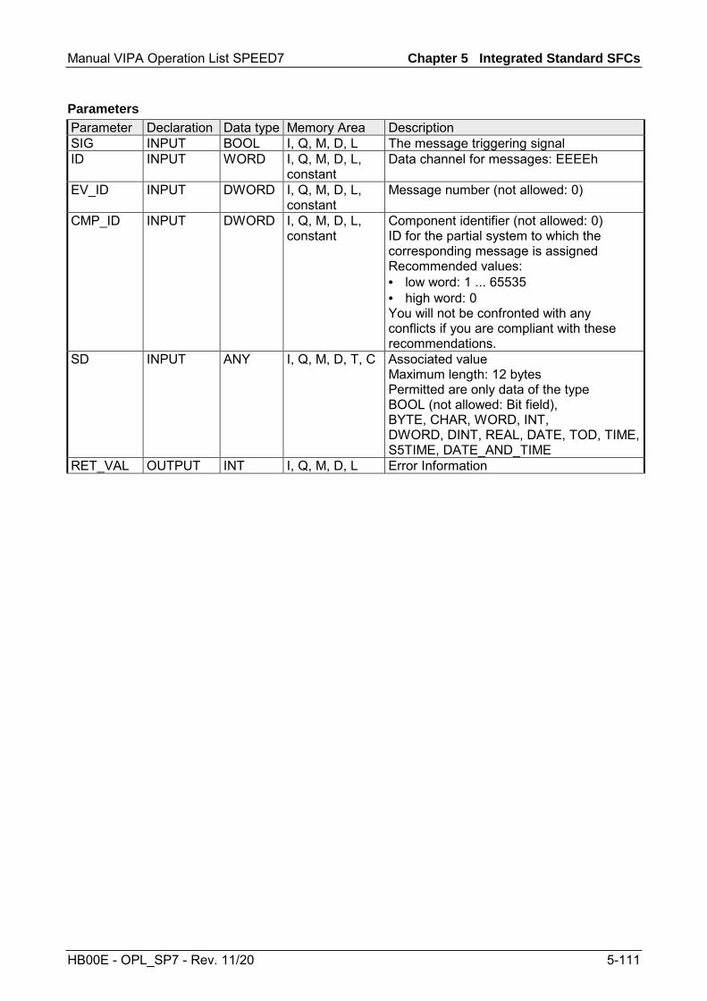
Manual VIPA Operation List SPEED7 Chapter 5 Integrated Standard SFCs
HB00E - OPL_SP7 - Rev. 11/20 5-111
Parameter Declaration Data type Memory Area Description SIG INPUT BOOL I, Q, M, D, L The message triggering signal ID INPUT WORD I, Q, M, D, L,
constant Data channel for messages: EEEEh
EV_ID INPUT DWORD I, Q, M, D, L, constant
Message number (not allowed: 0)
CMP_ID INPUT DWORD I, Q, M, D, L, constant
Component identifier (not allowed: 0) ID for the partial system to which the corresponding message is assigned Recommended values: • low word: 1 ... 65535 • high word: 0 You will not be confronted with any conflicts if you are compliant with these recommendations.
SD INPUT ANY I, Q, M, D, T, C Associated value Maximum length: 12 bytes Permitted are only data of the type BOOL (not allowed: Bit field), BYTE, CHAR, WORD, INT, DWORD, DINT, REAL, DATE, TOD, TIME, S5TIME, DATE_AND_TIME
RET_VAL OUTPUT INT I, Q, M, D, L Error Information
Parameters

Chapter 5 Integrated Standard SFCs Manual VIPA Operation List SPEED7
5-112 HB00E - OPL_SP7 - Rev. 11/20
Error code Description 0000h No error occurred. 0001h • The length of the associated value exceeds the maximum permissible length, or
• Access to user memory not possible (for example, access to deleted DB). The activated message is sent.
• The associated value points to a value in the local data area. The message is sent. (S7-400 only)
0002h Warning: The last free message acknowledge memory was occupied. (S7-400 only)8081h The specified EV_ID lies outside the valid range. 8082h Message loss because your CPU has no more resource for generating block related
messages with SFCs. 8083h Message loss, the same signal transition is already present but could not be sent yet
(signal overflow). 8084h With the current and the previous SFC 107-/SFC-108 call the message triggering
signal SIG has the same value. 8085h There is no logon for the specified EV_ID. 8086h An SFC call for the specified EV_ID is already being processed in a lower priority
class. 8087h At the initial call of SFC 107/SFC 108 the message triggering signal had the value 0.8088h The specified EV_ID is already in use by another system resource (to SFC 17, 18,
107, 108). 8089h You have assigned the value 0 to CMP_ID. 808Ah CMP_ID not fit to EV_ID 8xyyh General error information, see Evaluating Errors with the Output Parameter
RET_VAL.
RET_VAL (Return value)

Manual VIPA Operation List SPEED7 Chapter 6 VIPA specific blocks
HB00E - OPL_SP7 - Rev. 11/20 6-1
Chapter 6 VIPA specific blocks
Here you find the description of the VIPA specific blocks that are exclusively used with PLCs from VIPA.
Topic Page Chapter 6 VIPA specific blocks ....................................................... 6-1
Overview .............................................................................................. 6-2 Include VIPA library.............................................................................. 6-4 Siemens S7 Communication - FB/SFB 8 ... FB 55 ............................... 6-5 FB/SFB 8 - USEND - Uncoordinated data transmission ....................... 6-6 FB/SFB 9 - URCV - Uncoordinated data reception............................... 6-8 FB/SFB 12 - BSEND - Sending data in blocks ................................... 6-10 FB/SFB 13 - BRCV - Receiving data in blocks ................................... 6-13 FB/SFB 14 - GET - Remote CPU read............................................... 6-16 FB/SFB 15 - PUT - Remote CPU write............................................... 6-18 FB 55 - IP_CONFIG - Progr. Communication Connections ................ 6-20 FB 60 - SEND - Send to System SLIO CP 040 .................................. 6-34 FB 61 - RECEIVE - Receive from System SLIO CP 040 .................... 6-36 FC 5 - AG_SEND / FC 6 - AG_RECV - CP 343 communication......... 6-38 FC 10 - AG_CNTRL - CP 343 communication ................................... 6-43 FC 200 - IBS_INIT.............................................................................. 6-50 FC 202 - IBS_SERVICE..................................................................... 6-52 FC 204 - IBS_LOOP, FC 205 - IBS_CYCLE ...................................... 6-54 FC 206 - IBS_IRQ .............................................................................. 6-56 FC 207 - IBS_PCP ............................................................................. 6-57 FC 208 - IBS_DIAG............................................................................ 6-59 SFB 7 - uS_TIME and SFC 53 - uS_TICK - Time measurement ........ 6-60 SFB 239 - FUNC ................................................................................ 6-61 SFC 193 - AI_OSZI - Oscilloscope-/FIFO function ............................. 6-62 SFC 194 - DP_EXCH......................................................................... 6-65 MMC access - SFC 208...215 and SFC 195....................................... 6-67 SFC 208 - FILE_OPN......................................................................... 6-68 SFC 209 - FILE_CRE......................................................................... 6-69 SFC 210 - FILE_CLO......................................................................... 6-70 SFC 211 - FILE_RD ........................................................................... 6-71 SFC 212 - FILE_WR .......................................................................... 6-72 SFC 213 - FILE_SEK ......................................................................... 6-74 SFC 214 - FILE_REN......................................................................... 6-75 SFC 215 - FILE_DEL ......................................................................... 6-76 SFC 195 - FILE_ATT.......................................................................... 6-77 PtP communication - SFC 216...218 .................................................. 6-78 SFC 216 - SER_CFG ......................................................................... 6-79 SFC 217 - SER_SND ......................................................................... 6-82 SFC 218 - SER_RCV ......................................................................... 6-86 SFC 219 - CAN_TLGR - CANopen communication........................... 6-88 SFC 254 - RW_SBUS - IBS communication ...................................... 6-91
Overview
Content

Chapter 6 VIPA specific blocks Manual VIPA Operation List SPEED7
6-2 HB00E - OPL_SP7 - Rev. 11/20
Overview
The integrated blocks are developed in machine-code and are therefore running with high speed. They do not occupy space in the internal application memory. The integrated blocks are called via the user application. The following pages list the VIPA specific blocks that may be called in the control application for special functions. The following VIPA specific blocks are available:
FB/SFB Label Description FB/SFB 8 USEND Uncoordinated data transmission FB/SFB 9 URCV Uncoordinated data reception FB/SFB 12 BSEND Sending data an blocks FB/SFB 13 BRCV Receiving data in blocks FB/SFB 14 GET Remote CPU read FB/SFB 15 PUT Remote CPU write FB 55 IP_CONFIG Programmed Communication Connections FB 60 SEND Send to CP 040 FB 61 RECEIVE Receive from CP 040
FC Label Description FC 5 AG_SEND Transfer data to Ethernet CP 343 FC 6 AG_RECV Receive data from CP FC 10 AG_CNTRL Check and control Ethernet CP 343 connections FC 200 IBS_INIT Registration and initialization of an INTERBUS master at the
CPU FC 202 IBS_SERVICE Service communication between CPU and INTERBUS master FC 204 IBS_LOOP Slow asynchronous data communication between CPU and
INTERBUS master (waits for master release) FC 205 IBS_CYCLE Fast asynchronous data communication between CPU and
INTERBUS master (waits not for master release) FC 206 IBS_IRQ Synchronous data communication between CPU and INTERBUS
master with synchronization via interrupt FC 207 IBS_PCP Peripherals Communication Protocol (PCP) communication for
instructions and parameters for INTERBUS slaves FC 208 IBS_DIAG Read diagnostic data from INTERBUS master res. INTERBUS
slaves
SFB Label Description SFB 7 TIMEMESS VIPA Micro second timer with difference evaluation SFB 239 FUNC Execute system internal functions
General
Overview

Manual VIPA Operation List SPEED7 Chapter 6 VIPA specific blocks
HB00E - OPL_SP7 - Rev. 11/20 6-3
SFC Label Description SFC 53 1) uS_TICK VIPA micro second timer SFC 192 CP_S_R internally used for FB 7 and FB 8 * SFC 193 AI_OSZI Oscilloscope-/FIFO function SCF 194 DPEXCH SPEED-Bus data transfer between DP master and CPU SFC 195 FILE_ATT Change VIPA file attributes SFC 196 AG_CNTRL internally used for FC 10 * SFC 198 AG_USEND internally used for FB/SFB 8 * SFC 199 AG_URCV internally used for FB/SFB 9 * SFC 200 AG_GET internally used for FB/SFB 14 * SFC 201 AG_PUT internally used for FB/SFB 15 * SFC 202 AG_BSEND internally used for FB/SFB 12 * SFC 203 AG_BRCV internally used for FB/SFB 13 * SFC 204 IP_CONF internally used for FB 55 IP_CONF * SFC 205 AG_SEND internally used for FC 5 AG_SEND * SFC 206 AG_RECV internally used for FC 6 AG_RECV * SFC 208 FILE_OPN Open VIPA file SFC 209 FILE_CRE Create VIPA file SFC 210 FILE_CLO Close VIPA file SFC 211 FILE_RD Read VIPA file SFC 212 FILE_WR Write VIPA file SFC 213 FILE_SEK Position VIPA file pointer SFC 214 FILE_REN Rename VIPA file SFC 215 FILE_DEL Delete VIPA file SFC 216 SER_CFG RS232 Parameterization SFC 217 SER_SND RS232 Send SFC 218 SER_RCV RS232 Receive SFC 219 CAN_TLGR Send CAN telegram SFC 253 IBS_ACCESS internally used for SPEED-Bus INTERBUS master * SFC 254 RW_SBUS Communication between SPEED-Bus INTERBUS master and
CPU 1) This function block is interruptable and does not affect the interrupt reaction time.
*) Note! To call the function please use exclusively the block listed here. The direct call of the associated internal SFC leads to errors in the corresponding instance DB!

Chapter 6 VIPA specific blocks Manual VIPA Operation List SPEED7
6-4 HB00E - OPL_SP7 - Rev. 11/20
Include VIPA library
The VIPA specific blocks may be found at www.vipa.de as downloadable library at the service area with Downloads > VIPA LIB. The library is available as packed zip-file. If you want to use VIPA specific blocks, you have to import the library into your project. Execute the following steps: • Extract FX000011_Vxxx.zip • "Retrieve" the library • Open library and transfer blocks into the project
Start your un-zip application with a double click on the file FX000011_Vxxx.zip and copy the file VIPA.ZIP to your work directory. It is not necessary to extract this file, too.
To retrieve your library for the SPEED7-CPUs, start the SIMATIC manager from Siemens. Open the dialog window for archive selection via File > Retrieve. Navigate to your work directory. Choose VIPA.ZIP and click at [Open]. Select a destination folder where the blocks are to be stored. [OK] starts the extraction.
After the extraction open the library. Open your project and copy the necessary blocks from the library into the directory "blocks" of your project. Now you have access to the VIPA specific blocks via your user application.
Overview
Unzip FX000011_Vxxx.zip
Retrieve library
Open library and transfer blocks to project

Manual VIPA Operation List SPEED7 Chapter 6 VIPA specific blocks
HB00E - OPL_SP7 - Rev. 11/20 6-5
Siemens S7 Communication - FB/SFB 8 ... FB 55
With Siemens S7 communication you can transfer large volumes of data between via Ethernet connected PLC stations based on Siemens STEP®7. The communication connections are static i.e. they are to be configured in a connection table.
• Siemens S7-300 communication functions By including the VIPA specific function blocks FB 8 ... FB 55 you get access to the Siemens S7-300 communication functions. More information for including the function blocks can be found above at "Include VIPA library".
• Siemens S7-400 communication functions To deploy the Siemens S7-400 communication functions the in the operating system of the CPU integrated system function blocks SFB 8 ... SFB 23 should be used. Here copy the interface description of the SFBs from the standard library at system function block to the directory container, generate an instance data block for each call and call the SFB with the associated instance data block.
Precondition for Siemens S7 communication is a configured connection table in which the communication links are defined. For this e.g. WinPLC7 from VIPA or NetPro from Siemens can be used. A communication link is specified by a connection ID for each communication partner. Use the local ID to initialize the FB/SFB in the PLC from which the connection is regarded and the partner ID to configure the FB/SFB in the partner PLC. The following function blocks can be used for Siemens S7 commu-nications:
FB/SFB Label Description FB/SFB 8 USEND Uncoordinated data transmission FB/SFB 9 URCV Uncoordinated data reception FB/SFB 12 BSEND Sending data in blocks FB/SFB 13 BRCV Receiving data in blocks FB/SFB 14 GET Remote CPU read FB/SFB 15 PUT Remote CPU write
FB 55 IP_CONFIG Programmed Communication Connections
Note! Please use for the Siemens S7 communication exclusively the FB/SFBs listed here. The direct call of the associated internal SFCs leads to errors in the corresponding instance DB!
Overview
Possibilities of communication functions
Configuring
Function blocks
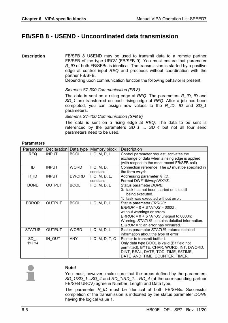
Chapter 6 VIPA specific blocks Manual VIPA Operation List SPEED7
6-6 HB00E - OPL_SP7 - Rev. 11/20
FB/SFB 8 - USEND - Uncoordinated data transmission
FB/SFB 8 USEND may be used to transmit data to a remote partner FB/SFB of the type URCV (FB/SFB 9). You must ensure that parameter R_ID of both FB/SFBs is identical. The transmission is started by a positive edge at control input REQ and proceeds without coordination with the partner FB/SFB. Depending upon communication function the following behavior is present:
Siemens S7-300 Communication (FB 8) The data is sent on a rising edge at REQ. The parameters R_ID, ID and SD_1 are transferred on each rising edge at REQ. After a job has been completed, you can assign new values to the R_ID, ID and SD_1 parameters. Siemens S7-400 Communication (SFB 8) The data is sent on a rising edge at REQ. The data to be sent is referenced by the parameters SD_1 ... SD_4 but not all four send parameters need to be used.
Parameter Declaration Data type Memory block Description
REQ INPUT BOOL I, Q, M, D, L Control parameter request, activates the exchange of data when a rising edge is applied (with respect to the most recent FB/SFB-call)
ID INPUT WORD I, Q, M, D, constant
Connection reference. The ID must be specified in the form wxyzh.
R_ID INPUT DWORD I, Q, M, D, L, constant
Addressing parameter R_ID. Format DW#16#wxyzWXYZ.
DONE OUTPUT BOOL I, Q, M, D, L Status parameter DONE: 0: task has not been started or it is still being executed. 1: task was executed without error.
ERROR OUTPUT BOOL I, Q, M, D, L Status parameter ERROR: ERROR = 0 + STATUS = 0000h: without warnings or errors ERROR = 0 + STATUS unequal to 0000h: Warning. STATUS contains detailed information. ERROR = 1: an error has occurred.
STATUS OUTPUT WORD I, Q, M, D, L Status parameter STATUS, returns detailed information about the type of error.
SD_i, 1≤ i ≤4
IN_OUT ANY I, Q, M, D, T, C Pointer to transmit buffer i. Only data type BOOL is valid (Bit field not permitted), BYTE, CHAR, WORD, INT, DWORD, DINT, REAL, DATE, TOD, TIME, S5TIME, DATE_AND_TIME, COUNTER, TIMER.
Note! You must, however, make sure that the areas defined by the parameters SD_1/SD_1...SD_4 and RD_1/RD_1... RD_4 (at the corresponding partner FB/SFB URCV) agree in Number, Length and Data type. The parameter R_ID must be identical at both FB/SFBs. Successful completion of the transmission is indicated by the status parameter DONE having the logical value 1.
Description
Parameters

Manual VIPA Operation List SPEED7 Chapter 6 VIPA specific blocks
HB00E - OPL_SP7 - Rev. 11/20 6-7
ERROR STATUS (decimal)
Description
0 11 Warning: the new task is not active, since the previous task has not completed.
0 25 Communications initiated. The task is being processed.
1 1 • Communication failures, e.g. Connection parameters not loaded (local or remote)
• Connection interrupted (e.g. cable, CPU turned off, CP in STOP)
1 4 Error in transmission range pointers SD_i with respect to the length or the data type.
1 10 Access to local application memory not possible (e.g. access to deleted DB).
1 12 The call to the FB/SFB • contains an instance DB that does not belong to
the FB/SFB 8 • contains a global DB instead of an instance DB • could not locate an instance DB
(load a new instance DB from the PG)
1 18 R_ID already exists in the connection ID. 1 20 Not enough memory.
To ensure the data consistency is not compromised, can the currently used transmission ranges SD_i be described again only if the current job is completed. This requires that the DONE parameter is evaluated. This is the case when the value of the status parameter DONE changes to 1.
Error information
Data consistency

Chapter 6 VIPA specific blocks Manual VIPA Operation List SPEED7
6-8 HB00E - OPL_SP7 - Rev. 11/20
FB/SFB 9 - URCV - Uncoordinated data reception
FB/SFB 9 URCV can be used to receive data asynchronously from a remote partner FB/SFB of the type USEND (FB/SFB 8). You must ensure that parameter R_ID of both FB/SFBs is identical. The block is ready to receive then there is a logical 1 at the EN_R input. An active job can be cancelled with EN_R=0. Depending upon communication function the following behavior is present:
Siemens S7-300 Communication (FB 9) The parameters R_ID, ID and RD_1 are applied with every positive edge on EN_R. After a job has been completed, you can assign new values to the R_ID, ID and RD_1 parameters. Siemens S7-400 Communication (SFB 9) The receive data areas are referenced by the parameters RD_1...RD_4.
Parameter Declaration Data type Memory block Description EN_R INPUT BOOL I, Q, M, D, L Control parameter enabled to receive,
indicates that the partner is ready for reception
ID INPUT WORD I, Q, M, D, constant
A reference for the connection. Format wxyzh
R_ID INPUT DWORD I, Q, M, D, L, constant
Address parameter R_ID. Format DW#16#wxyzWXYZ.
NDR OUTPUT BOOL I, Q, M, D, L Status parameter NDR: new data transferred.
ERROR OUTPUT BOOL I, Q, M, D, L Status parameter ERROR: ERROR = 0 + STATUS=0000h: without warnings or errors ERROR = 0 + STATUS unequal to 0000h: Warning. STATUS contains detailed information. ERROR = 1: an error has occurred.
STATUS OUTPUT WORD I, Q, M, D, L Status parameter STATUS, returns detailed information about the type of error.
RD_i, 1≤ i ≤4
IN_OUT ANY I, Q, M, D, T, C Pointer to receive buffer i. Only data type BOOL is valid (Bit field not permitted), BYTE, CHAR, WORD, INT, DWORD, DINT, REAL, DATE, TOD, TIME, S5TIME, DATE_AND_TIME, COUNTER, TIMER.
Note! The quantity, length and data type of the buffer areas defined by parameters SD_i and RD_i, 1 ≤ i ≤ 4 must be identical (RD_i is the receive buffer of the respective partner FB/SFB, see FB/SFB 8). The initial call to FB/SFB 9 creates the "receive box". The receive data available during any subsequent calls must fit into this receive box. When a data transfer completes successfully parameter NDR is set to 1.
Description
Parameters
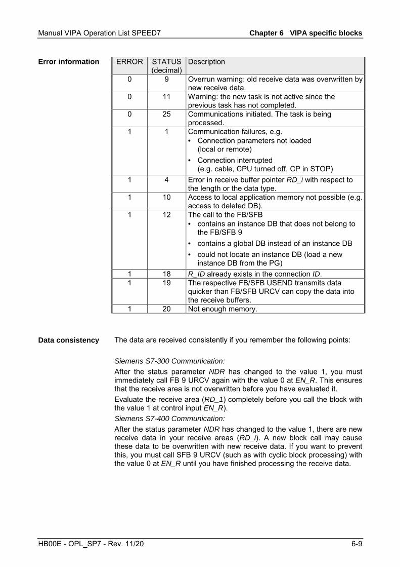
Manual VIPA Operation List SPEED7 Chapter 6 VIPA specific blocks
HB00E - OPL_SP7 - Rev. 11/20 6-9
ERROR STATUS (decimal)
Description
0 9 Overrun warning: old receive data was overwritten by new receive data.
0 11 Warning: the new task is not active since the previous task has not completed.
0 25 Communications initiated. The task is being processed.
1 1 Communication failures, e.g. • Connection parameters not loaded
(local or remote) • Connection interrupted
(e.g. cable, CPU turned off, CP in STOP) 1 4 Error in receive buffer pointer RD_i with respect to
the length or the data type. 1 10 Access to local application memory not possible (e.g.
access to deleted DB). 1 12 The call to the FB/SFB
• contains an instance DB that does not belong to the FB/SFB 9
• contains a global DB instead of an instance DB • could not locate an instance DB (load a new
instance DB from the PG) 1 18 R_ID already exists in the connection ID. 1 19 The respective FB/SFB USEND transmits data
quicker than FB/SFB URCV can copy the data into the receive buffers.
1 20 Not enough memory.
The data are received consistently if you remember the following points: Siemens S7-300 Communication: After the status parameter NDR has changed to the value 1, you must immediately call FB 9 URCV again with the value 0 at EN_R. This ensures that the receive area is not overwritten before you have evaluated it. Evaluate the receive area (RD_1) completely before you call the block with the value 1 at control input EN_R). Siemens S7-400 Communication: After the status parameter NDR has changed to the value 1, there are new receive data in your receive areas (RD_i). A new block call may cause these data to be overwritten with new receive data. If you want to prevent this, you must call SFB 9 URCV (such as with cyclic block processing) with the value 0 at EN_R until you have finished processing the receive data.
Error information
Data consistency

Chapter 6 VIPA specific blocks Manual VIPA Operation List SPEED7
6-10 HB00E - OPL_SP7 - Rev. 11/20
FB/SFB 12 - BSEND - Sending data in blocks
FB/SFB 12 BSEND sends data to a remote partner FB/SFB of the type BRCV (FB/SFB 13). The data area to be transmitted is segmented. Each segment is sent individually to the partner. The last segment is acknowledged by the partner as it is received, independently of the calling up of the corresponding FB/SFB/FB BRCV. With this type of data transfer, more data can be transported between the communications partners than is possible with all other communication FBs/SFBs for configured S7 connections, namely 65534 bytes. Depending upon communication function the following behavior is present: Siemens S7-300 Communication (FB 12) The send job is activated on a rising edge at REQ. The parameters R_ID, ID, SD_1 and LEN are transferred on each positive edge at REQ. After a job has been completed, you can assign new values to the R_ID, ID, SD_1 and LEN parameters. For the transmission of segmented data the block must be called periodically in the user program. The start address and the maximum length of the data to be sent are specified by SD_1. You can determine the job-specific length of the data field with LEN. Siemens S7-400 Communication (SFB 12) The send job is activated after calling the block and when there is a rising edge at REQ. Sending the data from the user memory is carried out asynchronously to the processing of the user program. The start address and the maximum length of the data to be sent are specified by SD_1. You can determine the job-specific length of the data field with LEN. In this case, LEN replaces the length section of SD_1.
If there is a rising edge at control input R, the current data transfer is canceled. Successful completion of the transfer is indicated by the status parameter DONE having the value 1. A new send job cannot be processed until the previous send process has been completed if the status parameter DONE or ERROR have the value 1. Due to the asynchronous data transmission, a new transmission can only be initiated if the previous data have been retrieved by the call of the partner FB/SFB. Until the data are retrieved, the status value 7 will be given when the FB/SFB BSEND is called. Note! The parameter R_ID must be identical at the two corresponding FBs/SFBs.
Description
Function

Manual VIPA Operation List SPEED7 Chapter 6 VIPA specific blocks
HB00E - OPL_SP7 - Rev. 11/20 6-11
Parameter Declaration Data type Memory block Description
REQ INPUT BOOL I, Q, M, D, L Control parameter request, a rising edge activates the data exchange (with respect to the most recent FB/SFB call)
R INPUT BOOL I, Q, M, D, L, constant
control parameter reset: terminates the active task
ID INPUT WORD I, Q, M, D, constant
A reference for the connection. Format wxyzh.
R_ID INPUT DWORD I, Q, M, D, L, constant
Address parameter R_ID. Format DW#16#wxyzWXYZ.
DONE OUTPUT BOOL I, Q, M, D, L Status parameter DONE: 0: task has not been started or is still being executed. 1: task was executed without error.
ERROR OUTPUT BOOL I, Q, M, D, L Status parameter ERROR: ERROR = 0 + STATUS = 0000h: without warnings or errors ERROR = 0 + STATUS unequal to 0000h: Warning. STATUS contains detailed information.ERROR = 1: an error has occurred.
STATUS OUTPUT WORD I, Q, M, D, L Status parameter STATUS, returns detailed information about the type of error.
SD_1 IN_OUT ANY I, Q, M, D, T, C Pointer to the send data buffer. The length parameter is only utilized when the block is called for the first time after a warm start or a cold start. It specifies the maximum length of the send buffer. Only data type BOOL is valid (Bit field not permitted), BYTE, CHAR, WORD, INT, DWORD, DINT, REAL, DATE, TOD, TIME, S5TIME, DATE_AND_TIME, COUNTER, TIMER.
LEN IN_OUT WORD I, Q, M, D, L The length of the send data block in bytes.
Parameters

Chapter 6 VIPA specific blocks Manual VIPA Operation List SPEED7
6-12 HB00E - OPL_SP7 - Rev. 11/20
ERROR STATUS
(decimal) Description
0 11 Warning: the new task is not active since the previous task has not completed.
0 25 The communication process was initiated. The task is being processed. 1 1 Communication failures, e.g. :
• Connection parameters not loaded (local or remote) • Connection interrupted (e.g. cable, CPU turned off, CP in STOP)
1 2 Negative acknowledgement received from the partner FB/SFB. The function cannot be executed.
1 3 R_ID is not available to the communication link specified by ID or the receive block has never been called.
1 4 Error in send buffer pointer SD_1 with respect to the length or the data type, or parameter LEN was set to 0 or an error has occurred in the receive data buffer pointer RD_1 of the respective FB/SFB 13 BRCV
1 5 Reset request was executed. 1 6 The status of the partner FB/SFB is DISABLED (EN_R has a value of 0) 1 7 The status of the partner FB/SFB is not correct (the receive block has not
been called after the most recent data transfer.) 1 8 Access to the remote object in application memory was rejected. 1 10 Access to local application memory not possible
(e.g. access to deleted DB). 1 12 The call to the FB/SFB
• contains an instance DB that does not belong to the FB/SFB 12
• contains a global DB instead of an instance DB • could not locate an instance DB (load a new
instance DB from the PG)
1 18 R_ID already exists in the connection ID. 1 20 Not enough memory.
To guarantee consistent data the segment of send buffer SD_1 that is currently being used can only be overwritten when current send process has been completed. For this purpose the program can test parameter DONE.
Error information
Data consistency
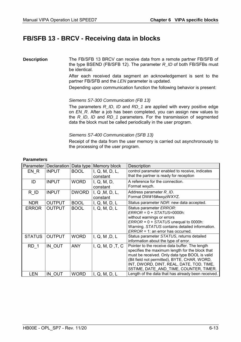
Manual VIPA Operation List SPEED7 Chapter 6 VIPA specific blocks
HB00E - OPL_SP7 - Rev. 11/20 6-13
FB/SFB 13 - BRCV - Receiving data in blocks
The FB/SFB 13 BRCV can receive data from a remote partner FB/SFB of the type BSEND (FB/SFB 12). The parameter R_ID of both FB/SFBs must be identical. After each received data segment an acknowledgement is sent to the partner FB/SFB and the LEN parameter is updated. Depending upon communication function the following behavior is present: Siemens S7-300 Communication (FB 13) The parameters R_ID, ID and RD_1 are applied with every positive edge on EN_R. After a job has been completed, you can assign new values to the R_ID, ID and RD_1 parameters. For the transmission of segmented data the block must be called periodically in the user program. Siemens S7-400 Communication (SFB 13) Receipt of the data from the user memory is carried out asynchronously to the processing of the user program.
Parameter Declaration Data type Memory block Description EN_R INPUT BOOL I, Q, M, D, L,
constant control parameter enabled to receive, indicates that the partner is ready for reception
ID INPUT WORD I, Q, M, D, constant
A reference for the connection. Format wxyzh.
R_ID INPUT DWORD I, Q ,M, D, L, constant
Address parameter R_ID. Format DW#16#wxyzWXYZ.
NDR OUTPUT BOOL I, Q, M, D, L Status parameter NDR: new data accepted. ERROR OUTPUT BOOL I, Q, M, D, L Status parameter ERROR:
ERROR = 0 + STATUS=0000h: without warnings or errors ERROR = 0 + STATUS unequal to 0000h: Warning. STATUS contains detailed information. ERROR = 1: an error has occurred.
STATUS OUTPUT WORD I, Q, M ,D, L Status parameter STATUS, returns detailed information about the type of error.
RD_1 IN_OUT ANY I, Q, M, D ,T, C Pointer to the receive data buffer. The length specifies the maximum length for the block that must be received. Only data type BOOL is valid (Bit field not permitted), BYTE, CHAR, WORD, INT, DWORD, DINT, REAL, DATE, TOD, TIME, S5TIME, DATE_AND_TIME, COUNTER, TIMER.
LEN IN_OUT WORD I, Q, M, D, L Length of the data that has already been received.
Description
Parameters

Chapter 6 VIPA specific blocks Manual VIPA Operation List SPEED7
6-14 HB00E - OPL_SP7 - Rev. 11/20
The FB/SFB 13 is ready for reception when control input EN_R is set to 1. Parameter RD_1 specifies the start address of the receive data buffer. An acknowledgement is returned to the partner FB/SFB after reception of each data segment and parameter LEN of the FB/SFB 13 is updated accordingly. If the block is called during the asynchronous reception process a warning is issued via the status parameter STATUS. Should this call be received with control input EN_R set to 0 then the receive process is terminated and the FB/SFB is reset to its initial state. When all data segments have been received without error parameter NDR is set to 1. The received data remains unaltered until FB/SFB 13 is called again with parameter EN_R = 1.
ERROR STATUS (decimal)
Description
0 11 Warning: the new task is not active since the previous task has not completed.
0 17 Warning: block is receiving asynchronous data. 0 25 Communications has been initiated.
The task is being processed. 1 1 Communication failures, e.g.
• Connection parameters not loaded (local or remote)
• Connection interrupted (e.g. cable, CPU turned off, CP in STOP)
1 2 Function cannot be executed. 1 4 Error in the receive data block pointer RD_1 with
respect to the length or the data type (the send data block is larger than the receive data block).
1 5 Reset request received, incomplete data transfer. 1 8 Access to the remote object in application memory
was rejected. 1 10 Access to local application memory not possible
(e.g. access to deleted DB). 1 12 The call to the FB/SFB
• contains an instance DB that does not belong to the FB/SFB 13
• contains a global DB instead of an instance DB • could not locate an instance DB (load a new
instance DB from the PG)
1 18 R_ID already exists in the connection ID. 1 20 Not enough memory.
Function
Error information
Manual VIPA Operation List SPEED7 Chapter 6 VIPA specific blocks
HB00E - OPL_SP7 - Rev. 11/20 6-15
To guarantee data consistency during reception the following points must be met: • When copying has been completed (parameter NDR is set to 1) FB/SFB
13 must again be called with parameter EN_R set to 0 in order to ensure that the receive data block is not overwritten before it has bee evaluated.
• The most recently used receive data block RD_1 must have been evaluated completely before the block is denoted as being ready to receive (calls with parameter EN_R set to 1).
Receiving Data S7-400 If a receiving CPU with a BRCV block ready to accept data (that is, a call with EN_R = 1 has already been made) goes into STOP mode before the corresponding send block has sent the first data segment for the job, the following will occur: • The data in the first job after the receiving CPU has gone into STOP
mode are fully entered in the receive area. • The partner SFB BSEND receives a positive acknowledgement. • Any additional BSEND jobs can no longer be accepted by a receiving
CPU in STOP mode. • As long as the CPU remains in STOP mode, both NDR and LEN have
the value 0. To prevent information about the received data from being lost, you must perform a hot restart of the receiving CPU and call SFB 13 BRCV with EN_R = 1.
Data consistency

Chapter 6 VIPA specific blocks Manual VIPA Operation List SPEED7
6-16 HB00E - OPL_SP7 - Rev. 11/20
FB/SFB 14 - GET - Remote CPU read
The FB/SFB 14 GET can be used to read data from a remote CPU. The respective CPU must be in RUN mode or in STOP mode. Depending upon communication function the following behavior is present: Siemens S7-300 Communication (FB 14) The data is read on a rising edge at REQ. The parameters ID, ADDR_1 and RD_1 are transferred on each rising edge at REQ. After a job has been completed, you can assign new values to the ID, ADDR_1 and RD_1 parameters. Siemens S7-400 Communication (SFB 14) The SFB is started with a rising edge at REQ. In the process the relevant pointers to the areas to be read out (ADDR_i) are sent to the partner CPU.
Parameter Declaration Data type Memory block Description REQ INPUT BOOL I, Q, M, D, L control parameter request, a rising edge
activates the data exchange (with respect to the most recent FB/SFB-call)
ID INPUT WORD I, Q, M, D, constant
A reference for the connection. Format wxyzh.
NDR OUTPUT BOOL I, Q, M, D, L Status parameter NDR: data from partner CPU has been accepted.
ERROR OUTPUT BOOL I, Q, M, D, L Status parameter ERROR: ERROR = 0 + STATUS=0000h: without warnings or errors ERROR = 0 + STATUS unequal to 0000h: Warning. STATUS contains detailed information. ERROR = 1: an error has occurred.
STATUS OUTPUT WORD I, Q, M, D, L Status parameter STATUS, returns detailed information about the type of error.
ADDR_1 IN_OUT ANY e.g. I, Q, M, D Pointer indicating the buffers in the partner CPU that must be read
ADDR_2 IN_OUT ANY e.g. I, Q, M, D Pointer indicating the buffers in the partner CPU that must be read
ADDR_3 IN_OUT ANY e.g. I, Q, M, D Pointer indicating the buffers in the partner CPU that must be read
ADDR_4 IN_OUT ANY e.g. I, Q, M, D Pointer indicating the buffers in the partner CPU that must be read
RD_i, 1≤ i ≤4
IN_OUT ANY I, Q, M, D, T, C Pointers to the area of the local CPU in which the read data are entered. Only data type BOOL is valid (Bit field not permitted), BYTE, CHAR, WORD, INT, DWORD, DINT, REAL, DATE, TOD, TIME, S5TIME, DATE_AND_TIME, COUNTER, TIMER.
Description
Parameters

Manual VIPA Operation List SPEED7 Chapter 6 VIPA specific blocks
HB00E - OPL_SP7 - Rev. 11/20 6-17
The remote CPU returns the data and the answer is checked for access problems during the read process for the data. The data type is checked in addition. When a data transfer error is detected the received data are copied into the configured receive data buffer (RD_i) with the next call to FB/SFB 14 and parameter NDR is set to 1. It is only possible to activate a new read process when the previous read process has been completed. You must ensure that the defined parameters on the ADDR_i and RD_i areas and the number that fit in quantity, length and data type of data to each other. ERROR STATUS
(decimal)Description
0 11 Warning: the new task is not active since the previous task has not completed.
0 25 The communication process was initiated. The task is being processed.
1 1 Communication failures, e.g. • Connection parameters not loaded
(local or remote) • Connection interrupted
(e.g. cable, CPU turned off, CP in STOP)
1 2 Negative acknowledgement from partner device. The function cannot be executed.
1 4 Error in receive data buffer pointer RD_i with respect to the length or the data type.
1 8 Partner CPU access error 1 10 Access to local application memory not possible
(e.g. access to deleted DB). 1 12 The call to the FB/SFB
• contains an instance DB that does not belong to the FB/SFB 14
• contains a global DB instead of an instance DB • could not locate an instance DB (load a new
instance DB from the PG)
1 20 Not enough memory.
The data are received consistently if you evaluate the current use of range RD_i completely before initiating another job.
Function
Error information
Data consistency

Chapter 6 VIPA specific blocks Manual VIPA Operation List SPEED7
6-18 HB00E - OPL_SP7 - Rev. 11/20
FB/SFB 15 - PUT - Remote CPU write
The FB/SFB 15 PUT can be used to write data to a remote CPU. The respective CPU may be in RUN mode or in STOP mode. Depending upon communication function the following behavior is present: Siemens S7-300 Communication (SB 15) The data is sent on a rising edge at REQ. The parameters ID, ADDR_1 and SD_1 are transferred on each rising edge at REQ. After a job has been completed, you can assign new values to the ID, ADDR_1 and SD_1 parameters. Siemens S7-400 Communication (SFB 15) The SFB is started on a rising edge at REQ. In the process the pointers to the areas to be written (ADDR_i) and the data (SD_i) are sent to the partner CPU.
Parameter Declaration Data type Memory block Description
REQ INPUT BOOL I, Q, M, D, L control parameter request, a rising edge activates the data exchange (with respect to the most recent FB/SFB-call)
ID INPUT WORD I, Q, M, D, constant
A reference for the connection. Format wxyzh.
DONE OUTPUT BOOL I, Q, M, D, L Status parameter DONE: function completed. ERROR OUTPUT BOOL I, Q, M, D, L Status parameter ERROR:
ERROR = 0 + STATUS=0000h: without warnings or errors ERROR = 0 + STATUS unequal to 0000h: Warning. STATUS contains detailed information. ERROR = 1: an error has occurred.
STATUS OUTPUT WORD I, Q, M, D, L Status parameter STATUS, returns detailed information about the type of error.
ADDR_1 IN_OUT ANY e.g. I, Q, M, D Pointer indicating the buffers in the partner CPU into which data is written
ADDR_2 IN_OUT ANY e.g. I, Q, M, D Pointer indicating the buffers in the partner CPU into which data is written
ADDR_3 IN_OUT ANY e.g. I, Q, M, D Pointer indicating the buffers in the partner CPU into which data is written
ADDR_4 IN_OUT ANY e.g. I, Q, M, D Pointer indicating the buffers in the partner CPU into which data is written
SD_i, 1≤i ≤4
IN_OUT ANY I, Q, M, D, T, C Pointer to the data buffers in the local CPU that contains the data that must be sent. Only data type BOOL is valid (Bit field not permitted), BYTE, CHAR, WORD, INT, DWORD, DINT, REAL, DATE, TOD, TIME, S5TIME, DATE_AND_TIME, COUNTER, TIMER.
Description
Parameters

Manual VIPA Operation List SPEED7 Chapter 6 VIPA specific blocks
HB00E - OPL_SP7 - Rev. 11/20 6-19
The partner CPU stores the data at the respective address and returns an acknowledgement. This acknowledgement is tested and when an error is detected in the data transfer parameter DONE is set to 1 with the next call of FB/SFB 15. The write process can only be activated again when the most recent write process has been completed. The amount, length and data type of the buffer areas that were defined by means of parameters ADDR_i and SD_i, 1 ≤ i ≤ 4 must be identical.
ERROR STATUS (decimal)
Description
0 11 Warning: the new task is not active since the previous task has not completed.
0 25 The communication process was initiated. The task is being processed.
1 1 Communication failures, e.g. • Connection parameters not loaded
(local or remote) • Connection interrupted
(e.g. cable, CPU turned off, CP in STOP)
1 2 Negative acknowledgement from partner device. The function cannot be executed.
1 4 Error in transmission range pointers SD_i with respect to the length or the data type.
1 8 Partner CPU access error 1 10 Access to local application memory not possible (e.g.
access to deleted DB). 1 12 The call to the FB/SFB
• contains an instance DB that does not belong to the FB/SFB 15.
• contains a global DB instead of an instance DB. • could not locate an instance DB (load a new
instance DB from the PG).
1 20 Not enough memory.
Siemens S7-300 Communication In order to ensure data consistency, send area SD_1 may not be used again for writing until the current send process has been completed. This is the case when the state parameter DONE has the value 1. Siemens S7-400 Communication When a send operation is activated (rising edge at REQ) the data to be sent from the send area SD_i are copied from the user program. After the block call, you can write to these areas without corrupting the current send data.
Function
Error information
Data consistency

Chapter 6 VIPA specific blocks Manual VIPA Operation List SPEED7
6-20 HB00E - OPL_SP7 - Rev. 11/20
FB 55 - IP_CONFIG - Progr. Communication Connections
In some situations, it is an advantage to set up communication connections not with Siemens NetPro but program-controlled by a specific application. A VIPA function block (FB 55) is available for these applications that allows flexible transfer of data blocks with configuration data to a CP.
Configuration data for communication connections may be transferred to the CPU by the FB 55 called in the user program.
FB 55 IP_CONF
Connection 1
System data for CP
Connection 2
Connection 64
.
.
.
Configuration datatransfered to the CP
DB
The configuration DB may be loaded into the CP at any time.
Attention! As soon as the user program transfers the connection data via FB 55 IP_CONFIG, the CPU switches the CP briefly to STOP. The CP accepts the system data (including IP address) and the new connection data and processes it during startup (RUN).
Overview
Principle
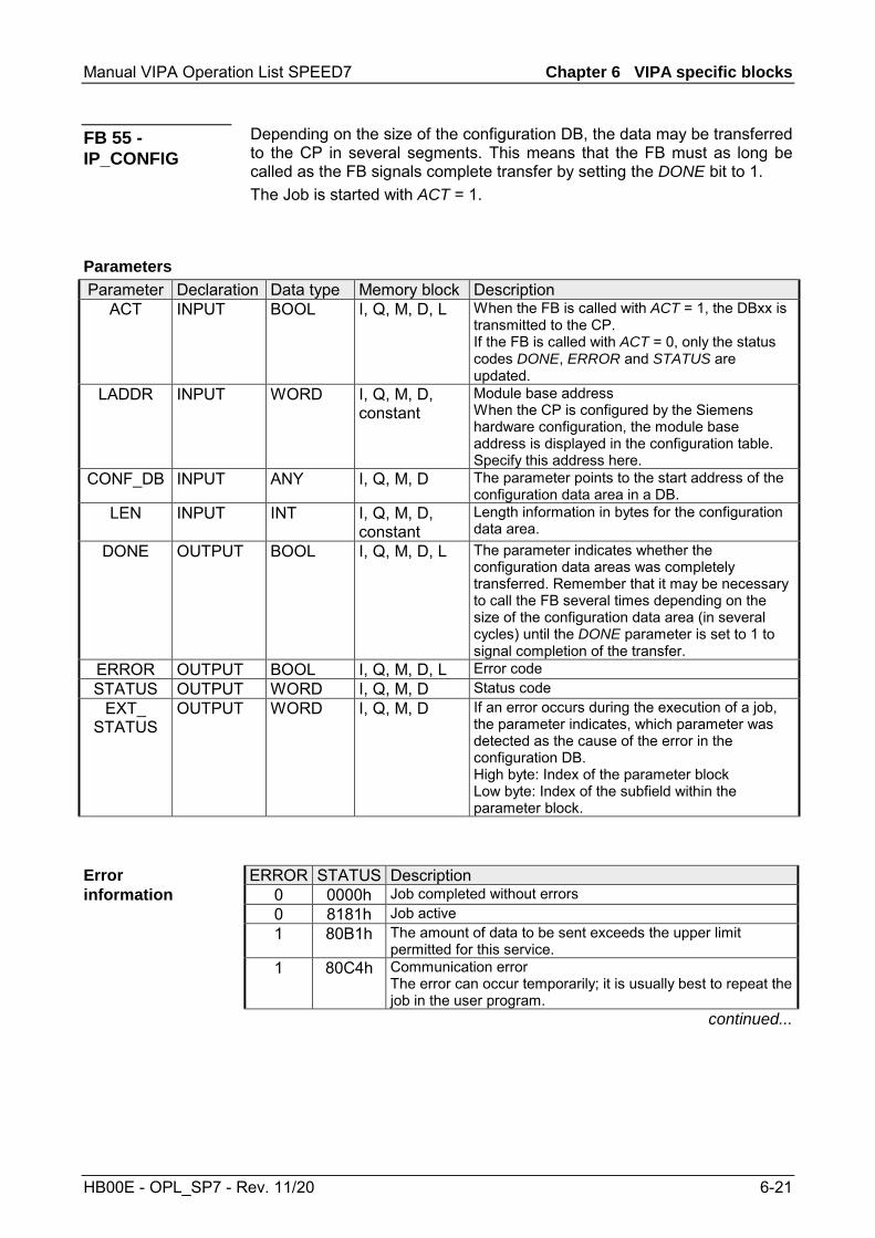
Manual VIPA Operation List SPEED7 Chapter 6 VIPA specific blocks
HB00E - OPL_SP7 - Rev. 11/20 6-21
Depending on the size of the configuration DB, the data may be transferred to the CP in several segments. This means that the FB must as long be called as the FB signals complete transfer by setting the DONE bit to 1. The Job is started with ACT = 1.
Parameter Declaration Data type Memory block Description
ACT INPUT BOOL I, Q, M, D, L When the FB is called with ACT = 1, the DBxx is transmitted to the CP. If the FB is called with ACT = 0, only the status codes DONE, ERROR and STATUS are updated.
LADDR INPUT WORD I, Q, M, D, constant
Module base address When the CP is configured by the Siemens hardware configuration, the module base address is displayed in the configuration table. Specify this address here.
CONF_DB INPUT ANY I, Q, M, D The parameter points to the start address of the configuration data area in a DB.
LEN INPUT INT I, Q, M, D, constant
Length information in bytes for the configuration data area.
DONE OUTPUT BOOL I, Q, M, D, L The parameter indicates whether the configuration data areas was completely transferred. Remember that it may be necessary to call the FB several times depending on the size of the configuration data area (in several cycles) until the DONE parameter is set to 1 to signal completion of the transfer.
ERROR OUTPUT BOOL I, Q, M, D, L Error code STATUS OUTPUT WORD I, Q, M, D Status code
EXT_ STATUS
OUTPUT WORD I, Q, M, D If an error occurs during the execution of a job, the parameter indicates, which parameter was detected as the cause of the error in the configuration DB. High byte: Index of the parameter block Low byte: Index of the subfield within the parameter block.
ERROR STATUS Description 0 0000h Job completed without errors 0 8181h Job active 1 80B1h The amount of data to be sent exceeds the upper limit
permitted for this service. 1 80C4h Communication error
The error can occur temporarily; it is usually best to repeat the job in the user program.
continued...
FB 55 - IP_CONFIG
Parameters
Error information

Chapter 6 VIPA specific blocks Manual VIPA Operation List SPEED7
6-22 HB00E - OPL_SP7 - Rev. 11/20
...continue ERROR STATUS Description
1 80D2h Configuration error, the module you are using does not support this service.
1 8183h The CP rejects the requested record set number. 1 8184h System error or illegal parameter type. 1 8185h The value of the LEN parameter is larger than the CONF_DB
less the reserved header (4bytes) or the length information is incorrect.
1 8186h Illegal parameter detected. The ANY pointer CONF_DB does not point to data block.
1 8187h Illegal status of the FB. Data in the header of CONF_DB was possibly overwritten.
1 8A01h The status code in the record set is invalid (value is >=3). 1 8A02h There is no job running on the CP; however the FB has
expected an acknowledgment for a competed job. 1 8A03h There is no job running on the CP and the CP is not ready;
the FB triggered the first job to read a record set. 1 8A04h There is no job running on the CP and the CP is not ready;
the FB nevertheless expected an acknowledgment for a completed job.
1 8A05h There is a job running, but there was no acknowledgment; the FB nevertheless triggered the first job for a read record set job.
1 8A06h A job is complete but the FB nevertheless triggered the first job for a read record sets job.
1 8B01h Communication error, the DB could not be transferred. 1 8B02h Parameter error, double parameter field 1 8B03h Parameter error, the subfield in the parameter field is not
permitted. 1 8B04h Parameter error, the length specified in the FB does not
match the length of the parameter fields/subfields. 1 8B05h Parameter error, the length of the parameter field is invalid. 1 8B06h Parameter error, the length of the subfield is invalid. 1 8B07h Parameter error, the ID of the parameter field is invalid. 1 8B08h Parameter error, the ID of the subfield is invalid. 1 8B09h System error, the connection does not exist. 1 8B0Ah Data error, the content of the subfield is not correct. 1 8B0Bh Structure error, a subfield exists twice. 1 8B0Ch Data error, the parameter does not contain all the necessary
parameters. 1 8B0Dh Data error, the CONF_DB does not contain a parameter field
for system data. continued...
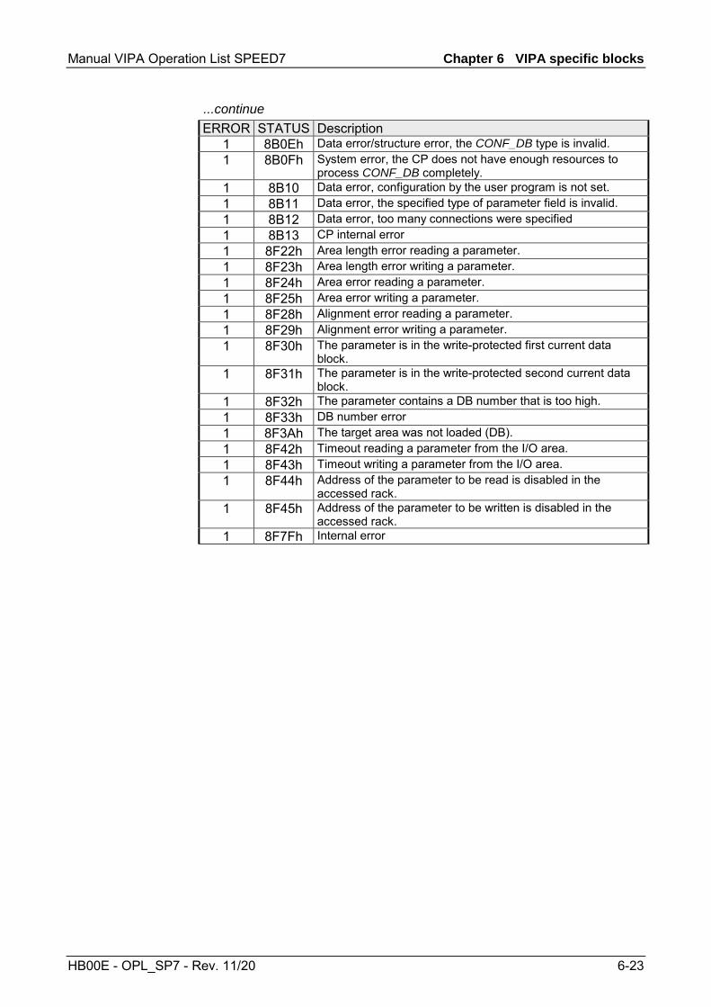
Manual VIPA Operation List SPEED7 Chapter 6 VIPA specific blocks
HB00E - OPL_SP7 - Rev. 11/20 6-23
...continue ERROR STATUS Description
1 8B0Eh Data error/structure error, the CONF_DB type is invalid. 1 8B0Fh System error, the CP does not have enough resources to
process CONF_DB completely. 1 8B10 Data error, configuration by the user program is not set. 1 8B11 Data error, the specified type of parameter field is invalid. 1 8B12 Data error, too many connections were specified 1 8B13 CP internal error 1 8F22h Area length error reading a parameter. 1 8F23h Area length error writing a parameter. 1 8F24h Area error reading a parameter. 1 8F25h Area error writing a parameter. 1 8F28h Alignment error reading a parameter. 1 8F29h Alignment error writing a parameter. 1 8F30h The parameter is in the write-protected first current data
block. 1 8F31h The parameter is in the write-protected second current data
block. 1 8F32h The parameter contains a DB number that is too high. 1 8F33h DB number error 1 8F3Ah The target area was not loaded (DB). 1 8F42h Timeout reading a parameter from the I/O area. 1 8F43h Timeout writing a parameter from the I/O area. 1 8F44h Address of the parameter to be read is disabled in the
accessed rack. 1 8F45h Address of the parameter to be written is disabled in the
accessed rack. 1 8F7Fh Internal error

Chapter 6 VIPA specific blocks Manual VIPA Operation List SPEED7
6-24 HB00E - OPL_SP7 - Rev. 11/20
The configuration data block (CONF_DB) contains all the connection data and configuration data (IP address, subnet mask, default router, NTP time server and other parameters) for an Ethernet CP. The configuration data block is transferred to the CP with function block FB 55. The CONF_DB can start at any point within a data block as specified by an offset range. The connections and specific system data are described by an identically structured parameter field.
DB identifier
System data for CP
Connection 1
Connection 2
Connection n
Offset range 0..nCONF_DB
ConfigurationData block Parameter field - System data
TypeID (for system data=0)Number of subfieldsSubfield 1
...Subfield n
Parameter field - Connections
Single parameterSubfield
TypeID (for system data=0)number of subfieldsSubfield 1
...Subfield n
Below, there are the subfields that are relevant for networking the CP. These must be specified in the parameter field for system data. Some applications do not require all the subfield types.
Type = 0
ID = 0
Number of subfields = n
Subfield 1
Subfield 2
Subfield n
Subfield Parameter ID Type Length
(byte) Description Special features Use
1 SUB_IP_V4 4 + 4 IP address of the local station according to IPv4
mandatory
2 SUB_NETMASK 4 + 4 Subnet mask of the local station mandatory 4 SUB_DNS_SERV_ADDR 4 + 4 DNS Server Address This subfield can
occur to 4 times. The first entry is the primary DNS server.
optional
8 SUB_DEF_ROUTER 4 + 4 IP address of the default router optional 14 SUB_DHCP_ENABLE 4 + 1 Obtain an IP address
from a DHCP. 0: no DHCP 1: DHCP
optional
15 SUB_CLIENT_ID Length Client-ID + 4
- - optional
Configuration Data Block
Structure
Parameter field for system data for CP
Structure

Manual VIPA Operation List SPEED7 Chapter 6 VIPA specific blocks
HB00E - OPL_SP7 - Rev. 11/20 6-25
There is shown below which values are needed to be entered in the parameter fields and which subfields are to be used for the various connection types. Some applications do not require all the subfield types. The ID parameter that precedes each connection parameter field beside the type ID is particularly important. On programmed connections this ID may freely be assigned within the permitted range of values. For identification of the connection this ID is to be used on the call interface of the FCs for the SEND/RECV. Range of values for the connection ID: 1, 2 ... 64
Type = 1
ID = Connection ID
Number of subfields = n
Subfield 1
Subfield 2
Subfield n
Subfield Parameter ID Type Length
(byte) Description Special features Use
1 SUB_IP_V4 4 + 4 IP address of the remote station according to IPv4 mandatory*)
9 SUB_LOC_PORT 4 + 2 Port of the local station mandatory 10 SUB_REM_PORT 4 + 2 Port of the remote station mandatory*)
18 SUB_CONNECT_NAME Length Name + 4
Name of the connection optional
19 SUB_LOC_MODE 4 + 1 Local mode of the connection, Possible values: 0x00 = SEND/REC 0x10 = S5-addressing mode for FETCH/WRITE **) 0x80 = FETCH **) 0x40 = WRITE **) If you do not set the parameter, the default setting is SEND/RECV. For FETCH/WRITE a passive connection setup is necessary.
optional
21 SUB_KBUS_ADR - - Value: fix 2 optional 22 SUB_CON_ESTABL 4 + 1 Type of connection establishment.
With this option, you specify whether the connection is established by this station. Possible values: 0 = passive; 1 = active
mandatory
*) Option using passive connection **) the coding may be combined with OR operations
Parameter fields for Connections
TCP Connection

Chapter 6 VIPA specific blocks Manual VIPA Operation List SPEED7
6-26 HB00E - OPL_SP7 - Rev. 11/20
Type = 2
ID = Connection ID
Number of subfields = n
Subfield 1
Subfield 2
Subfield n
Subfield Parameter ID Type Length
(byte) Description Special features Use
1 SUB_IP_V4 4 + 4 IP address of the remote station according to IPv4
mandatory
9 SUB_LOC_PORT 4 + 2 Port of the local station mandatory 10 SUB_REM_PORT 4 + 2 Port of the remote station mandatory 18 SUB_CONNECT_NAME Length
Name + 4 Name of the connection optional
19 SUB_LOC_MODE 4 + 1 Local mode of the connection Possible values: 0x00 = SEND/REC 0x10 = S5-addressing mode for FETCH/WRITE *) 0x80 = FETCH *) 0x40 = WRITE *) If you do not set the parameter, the default setting is SEND/RECV. For FETCH/WRITE a passive connection setup is necessary
optional
21 SUB_KBUS_ADR - - Value: fix 2 optional 23 SUB_ADDR_IN_DATA_
BLOCK 4 + 1 Select free UDP
connection. The remote node is entered in the job header of the job buffer by the user program when it calls AG_SEND. This allows any node on Ethernet/LAN/WAN to be reached. Possible values: 1 = free UDP connection 0 = otherwise
If the "Free UDP connection" is selected for this parameter, the parameters SUB_IP_V4, SUB_LOC_PORT SUB_REM_PORT are omitted.
optional
*) the coding may be combined with OR operations
UDP Connection

Manual VIPA Operation List SPEED7 Chapter 6 VIPA specific blocks
HB00E - OPL_SP7 - Rev. 11/20 6-27
Type = 3
ID = Connection ID
Number of subfields = n
Subfield 1
Subfield 2
Subfield n
Subfield Parameter ID Type Length
(byte) Description Special features Use
1 SUB_IP_V4 4 + 4 IP address of the remote station according to IPv4
mandatory*)
11 SUB_LOC_PORT Length TSAP + 4
TSAP of the local station mandatory
12 SUB_REM_PORT Length TSAP + 4
TSAP of the remote station mandatory*)
18 SUB_CONNECT_NAME Length Name + 4
Name of the connection optional
19 SUB_LOC_MODE 4 + 1 Local mode of the connection Possible values: 0x00 = SEND/RECV 0x10 = S5-addressing mode for FETCH/WRITE **) 0x80 = FETCH **) 0x40 = WRITE **) If you do not set the parameter, the default setting is SEND/RECV. For FETCH/WRITE a passive connection setup is necessary
optional
21 SUB_KBUS_ADR - - Value: fix 2 optional 22 SUB_CON_ESTABL 4 + 1 Type of connection establishment
With this option, you specify whether the connection is established by this station. Possible values: 0 = passive; 1 = active
mandatory
*) option using passive connection **) the coding may be combined with OR operation
ISO-on-TCP
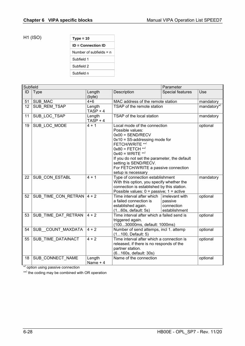
Chapter 6 VIPA specific blocks Manual VIPA Operation List SPEED7
6-28 HB00E - OPL_SP7 - Rev. 11/20
Type = 10
ID = Connection ID
Number of subfields = n
Subfield 1
Subfield 2
Subfield n
Subfield Parameter ID Type Length
(byte) Description Special features Use
51 SUB_MAC 4+6 MAC address of the remote station mandatory 12 SUB_REM_TSAP Length
TASP + 4 TSAP of the remote station mandatory*)
11 SUB_LOC_TSAP Length TASP + 4
TSAP of the local station mandatory
19 SUB_LOC_MODE 4 + 1 Local mode of the connection Possible values: 0x00 = SEND/RECV 0x10 = S5-addressing mode for FETCH/WRITE **) 0x80 = FETCH **) 0x40 = WRITE **) If you do not set the parameter, the default setting is SEND/RECV. For FETCH/WRITE a passive connection setup is necessary
optional
22 SUB_CON_ESTABL 4 + 1 Type of connection establishment With this option, you specify whether the connection is established by this station. Possible values: 0 = passive; 1 = active
mandatory
52 SUB_TIME_CON_RETRAN 4 + 2 Time interval after which a failed connection is established again. (1...60s, default: 5s)
irrelevant with passive connection establishment
optional
53 SUB_TIME_DAT_RETRAN 4 + 2 Time interval after which a failed send is triggered again. (100...30000ms, default: 1000ms)
optional
54 SUB__COUNT_MAXDATA 4 + 2 Number of send attemps, incl 1. attemp (1...100, Default: 5)
optional
55 SUB_TIME_DATAINACT 4 + 2 Time interval after which a connection is released, if there is no responds of the partner station. (6...160s, default: 30s)
optional
18 SUB_CONNECT_NAME Length Name + 4
Name of the connection optional
*) option using passive connection **) the coding may be combined with OR operation
H1 (ISO)

Manual VIPA Operation List SPEED7 Chapter 6 VIPA specific blocks
HB00E - OPL_SP7 - Rev. 11/20 6-29
Type = 11
ID = Connection ID
Number of subfields = n
Subfield 1
Subfield 2
Subfield n
Subfield Parameter ID Type Length
(byte) Description Special features Use
56 SUB_S7_C_DETAIL 4 + 14 Connection specific parameter (see below) mandatory 1 SUB_IP_V4 4 + 4 IP address according
to IPv4 IP address of the remote partner
mandatory*)
51 SUB_MAC 4 + 6 MAC address of the remote station mandatory 22 SUB_CON_ESTABL 4 + 1 Type of connection establishment
With this option, you specify whether the connection is established by this station. Possible values: 0 = passive; 1 = active
mandatory
18 SUB_CONNECT_NAME Length Name + 4
Name of the connection optional
*) option using passive connection
SUB_S7_C_DETAIL Parameter Declaration Data type Description SubBlockID IN WORD ID SubBlockLen IN WORD Length TcpIpActive IN INT Connection via MAC or IP address
(MAC=0, IP=1) LocalResource IN WORD Local resource 0001h ... 00DFh
(1=PG, 2=OP, 0010h ... 00DFh=not specified) LocalRack IN WORD Number local rack 0000h ... 0002h LocalSlot IN WORD Number local slot 0002h ... 000Fh
(2=CPU, 4=VIPA-PG/OP, 5=CP int., 6=CP ext.) RemoteResource IN WORD Remote resource 0001h ... 00DFh
(1=PG, 2=OP, 0010h ... 00DFh=not specified) RemoteRack IN WORD Number remote rack 0000h ... 0002h RemoteSlot IN WORD Number remote slot 0002h ... 000Fh
(2=CPU, 4=VIPA-PG/OP, 5=CP int., 6=CP ext.) The "local TSAP" is created with LocalResource, LocalRack and LocalSlot. The "remote TSAP" is created with RemoteResource, RemoteRack and RemoteSlot.
Siemens S7

Chapter 6 VIPA specific blocks Manual VIPA Operation List SPEED7
6-30 HB00E - OPL_SP7 - Rev. 11/20
The configuration of a dynamic Siemens S7 connection via IP_CONF takes place analog to the configuration of a fix Siemens S7 connection with Siemens NetPro Based on Siemens NetPro there are the following parameters corres-ponding to the following subfields: "Properties - Siemens S7- Connection" Siemens NetPro FB55 - IP_CONFIG establish an active connection SUB_CON_ESATBL.CON_ESTABL TCP/IP SUB_S7_C_DETAILS.TcpIpActive IP respectively MAC address remote station
SUB_IP_V4.rem_IP.IP_0...IP_3 resp. SUB_MAC.rem_MAC.MAC_0...MAC5
Local ID Connection ID "Address details" Siemens NetPro FB55 - IP_CONFIG Local rack SUB_S7_C_DETAILS.LocalRack Local slot SUB_S7_C_DETAILS.LocalSlot Local resource SUB_S7_C_DETAILS.LocalResource Remote rack SUB_S7_C_DETAILS.RemoteRack Remote slot SUB_S7_C_DETAILS.RemoteSlot Remote resource SUB_S7_C_DETAILS.RemoteResource
Example for configuring a Siemens S7 connection

Manual VIPA Operation List SPEED7 Chapter 6 VIPA specific blocks
HB00E - OPL_SP7 - Rev. 11/20 6-31
As soon as the Block_VIPA_HWK (special identification 99) is contained in the DB, all connections, which were parameterized in the NETPRO, are still remain. Now it is possible to change with IP_CONFIG only the system data (IP, Netmask etc.). If the special identification Block_VIPA_HWK were found, no other connecting data may be parameterized in the DB, otherwise error is announced in the RETVAL. If the Block_VIPA_HWK is not in the DB, then all connections are removed from NETPRO (as with Siemens) and the connections from this DB are only configured.
Type = 99
ID = 0
Number of subfields = 0
As soon as the Block_VIPA_BACNET (special identification 100) is contained in the DB, a BACNET configuration is derived from the DB and no further blocks are evaluated thereafter.
Type = 100
Number of subfields = 0
Type = 101
ID = Connection ID
Number of subfields = n
Subfield 1
Subfield 2
Subfield n
Subfield Parameter ID Type Length (byte) Description Special features Use 1 VIPA_IPK_CYCLE 4 + 4 IPK cycle time for
connection ID VIPA specific optional
Additional Parameter fields
Block_VIPA_HWK
Block_VIPA_ BACNET
Block_VIPA_IPK

Chapter 6 VIPA specific blocks Manual VIPA Operation List SPEED7
6-32 HB00E - OPL_SP7 - Rev. 11/20
Address Name Type Initial value Actual Comment 0.0 DB_Ident WOR W#16#1 W#16#1 2.0 Systemdaten.Typ INT 0 0 System data 4.0 Systemdaten.VerbId INT 0 0 fix 0 6.0 Systemdaten.SubBlock_Anzahl INT 3 3 8.0 Systemdaten.ip.SUB_IP_V4 WOR W#16#1 W#16#1
10.0 Systemdaten.ip. SUB_IP_V4_LEN WOR W#16#8 W#16#8 12.0 Sys temdaten. ip . IP_0 BYTE B#16#0 B#16#AC 13.0 Sys temdaten. ip . IP_1 BYTE B#16#0 B#16#14 14.0 Sys temdaten. ip . IP_2 BYTE B#16#0 B#16#8B 15.0 Sys temdaten. ip . IP_3 BYTE B#16#0 B#16#61 16.0 Systemdaten.netmask.SUB_NETMASK WOR W#16#2 W#16#2 18.0 Systemdaten.netmask. SUB_NETMASK _LEN WOR W#16#8 W#16#8 20.0 Systemdaten.netmask.NETMASK_0 BYTE B#16#0 B#16#FF 21.0 Systemdaten.netmask.NETMASK_1 BYTE B#16#0 B#16#FF 22.0 Systemdaten.netmask.NETMASK_2 BYTE B#16#0 B#16#FF 23.0 Systemdaten.netmask.NETMASK_3 BYTE B#16#0 B#16#0 24.0 Systemdaten. router.SUB_DEF_ROUTER WOR W#16#8 W#16#8 26.0 Systemdaten.router. SUB_DEF_ROUTER WOR W#16#8 W#16#8 28.0 Systemdaten.router.ROUTER_0 BYTE B#16#0 B#16#AC 29.0 Systemdaten.router.ROUTER_1 BYTE B#16#0 B#16#14 30.0 Systemdaten.router.ROUTER_2 BYTE B#16#0 B#16#8B 31.0 Systemdaten.router.ROUTER_3 BYTE B#16#0 B#16#61 32.0 Con_TCP_ID1.Typ INT 1 1 TCP connection 34.0 Con_TCP_ID1.VerbId INT 0 1 Connection ID36.0 Con_TCP_ID1.SubBlock_Anzahl INT 4 4 38.0 Con_TCP_ID1.ip1.SUB_IP_V4 WOR W#16#1 W#16#1 40.0 Con_TCP_ID1.ip1. SUB_IP_V4_LEN WOR W#16#8 W#16#8 42.0 Con_TCP_ID1.ip1.IP_0 BYTE B#16#0 B#16#AC 43.0 Con_TCP_ID1.ip1.IP_1 BYTE B#16#0 B#16#14 44.0 Con_TCP_ID1.ip1.IP_2 BYTE B#16#0 B#16#8B 45.0 Con_TCP_ID1.ip1.IP_3 BYTE B#16#0 B#16#62 46.0 Con_TCP_ID1.locport.SUB_LOC_PORT WOR W#16#9 W#16#9 48.0 Con_TCP_ID1.locport. SUB_LOC_PORT _LEN WOR W#16#6 W#16#6 50.0 Con_TCP_ID1.locport.LOC_PORT WOR W#16#0 W#16#3E9 52.0 Con_TCP_ID1.remport. SUB_REM_PORT WOR W#16#A W#16#A 54.0 Con_TCP_ID1.remport. SUB_REM_PORT WOR W#16#6 W#16#6 56.0 Con_TCP_ID1.remport.REM_PORT WOR W#16#0 W#16#3E9 58.0 Con_TCP_ID1.con_est.SUB_CON_ESTABL WOR W#16#16 W#16#16 60.0 Con_TCP_ID1.con_est. SUB_CON_ESTABL WOR W#16#6 W#16#6 62.0 Con_TCP_ID1.con_est.CON_ESTABL BYTE B#16#0 B#16#1 64.0 Con_ISO_ID3.Typ INT 3 3 ISO-on-TCP connection 66.0 Con_ISO_ID3.VerbId INT 0 3 Connectuion ID 68.0 Con_ISO_ID3.SubBlock_Anzahl INT 4 4 70.0 Con_ISO_ID3.ip1. SUB_IP_V4 WOR W#16#1 W#16#1 72.0 Con_ISO_ID3.ip1. SUB_IP_V4_LEN WOR W#16#8 W#16#8 74.0 Con_ISO_ID3.ip1.IP_0 BYTE B#16#0 B#16#AC 75.0 Con_ISO_ID3.ip1.IP_1 BYTE B#16#0 B#16#10 76.0 Con_ISO_ID3.ip1.IP_2 BYTE B#16#0 B#16#8B 77.0 Con_ISO_ID3.ip1.IP_3 BYTE B#16#0 B#16#62 78.0 Con_ISO_ID3.loc_TSAP.SUB_LOC_PORT WOR W#16#B W#16#B 80.0 Con_ISO_ID3.loc_TSAP. SUB_LOC_PORT WOR W#16#A W#16#A 82.0 Con_ISO_ID3.loc_TSAP.LOC_TSAP[0] BYTE B#16#0 B#16#54 83.0 Con_ISO_ID3.loc_TSAP.LOC_TSAP[1] BYTE B#16#0 B#16#53 84.0 Con_ISO_ID3.loc_TSAP.LOC_TSAP[2] BYTE B#16#0 B#16#41 85.0 Con_ISO_ID3.loc_TSAP.LOC_TSAP[3] BYTE B#16#0 B#16#50 86.0 Con_ISO_ID3.loc_TSAP.LOC_TSAP[4] BYTE B#16#0 B#16#30 87.0 Con_ISO_ID3.loc_TSAP.LOC_TSAP[5] BYTE B#16#0 B#16#31 88.0 Con_ISO_ID3.rem_TSAP. SUB_REM_PORT WOR W#16#C W#16#C 90.0 Con_ISO_ID3.rem_TSAP. SUB_REM_PORT WOR W#16#A W#16#A 92.0 Con_ISO_ID3.rem_TSAP.REM_TSAP[0] BYTE B#16#0 B#16#54 93.0 Con_ISO_ID3.rem_TSAP.REM_TSAP[1] BYTE B#16#0 B#16#53 94.0 Con_ISO_ID3.rem_TSAP.REM_TSAP[2] BYTE B#16#0 B#16#41
continued ...
Example DB

Manual VIPA Operation List SPEED7 Chapter 6 VIPA specific blocks
HB00E - OPL_SP7 - Rev. 11/20 6-33
... continue Address Name Type Initial value Actual Comment
95.0 Con_ISO_ID3.rem_TSAP.REM_TSAP[3] BYTE B#16#0 B#16#50 96.0 Con_ISO_ID3.rem_TSAP.REM_TSAP[4] BYTE B#16#0 B#16#30 97.0 Con_ISO_ID3.rem_TSAP.REM_TSAP[5] BYTE B#16#0 B#16#31 98.0 Con_ISO_ID3.con_est.SUB_CON_ESTABL WORD W#16#16 W#16#16
100.0 Con_ISO_ID3.con_est.SUB_CON_ESTABL_LEN WORD W#16#6 W#16#6 102.0 Con_ISO_ID3.con_est.CON_ESTABL BYTE B#16#0 B#16#1 104.0 S7_Verb .Typ INT 11 11 S7 connection 106.0 S7_Verb.Verb_ID INT 0 0 Connection ID 108.0 S7_Verb.SubBlock_Anzahl INT 5 5 110.0 S7_Verb.Verb_Parameter.SUB_S7_C_DETAIL INT 56 56 112.0 S7_Verb.Verb_Parameter. SUB_S7_C_DETAIL_LEN INT 18 18 114.0 S7_Verb.Verb_Parameter.TcpIpActive INT 0 1 116.0 S7_Verb.Verb_Parameter.LocalResource INT 0 2 118.0 S7_Verb.Verb_Parameter.LocalRack INT 0 0 120.0 S7_Verb.Verb_Parameter.LocalsSlot INT 0 2 122.0 S7_Verb.Verb_Parameter.RemoteResource INT 0 2 124.0 S7_Verb.Verb_Parameter.RemoteRack INT 0 0 126.0 S7_Verb.Verb_Parameter.RemoteSlot INT 0 2 128.0 S7_Verb. ip l .SUB_IP_V4 WORD W#16#1 W#16#1 130.0 S7_Verb.ipl. SUB_IP_V4_LEN WORD W#16#8 W#16#8 132.0 S7_Verb. ip l . IP_0 BYTE B#16#0 B#16#AC 133.0 S7_Verb . i p l . I P_1 BYTE B#16#0 B#16#10 134.0 S7_Verb. ip l . IP_2 BYTE B#16#0 B#16#8B 135.0 S7_Verb. ip l . IP_3 BYTE B#16#0 B#16#62 136.0 S7_Verb.Mac.SUB_MAC INT 51 51 138.0 S7_Verb.Mac. SUB_MAC _LEN INT 10 10 140.0 S7_Verb.Mac.MAC_0 BYTE B#16#0 B#16#0 141.0 S7_Verb.Mac.MAC_1 BYTE B#16#0 B#16#20 142.0 S7_Verb.Mac.MAC_2 BYTE B#16#0 B#16#D5 143.0 S7_Verb.Mac.MAC_3 BYTE B#16#0 B#16#77 144.0 S7_Verb.Mac.MAC_4 BYTE B#16#0 B#16#53 145.0 S7_Verb.Mac.MAC_5 BYTE B#16#0 B#16#9B 146.0 S7_Verb.con_est .SUB_CON_ESTABL WORD W#16#16 W#16#16 148.0 S7_Verb.con_est. SUB_CON_ESTABL _LEN WORD W#16#6 W#16#6 150.0 S7_Verb.con_est.CON_ESTABL BYTE B#16#0 B#16#1 152.0 S7_Verb.name_verb.SUB_CONNECT_NAME WORD W#16#12 W#16#12 154.0 S7_Verb.name_verb. SUB_CONNECT_NAME _LEN WORD W#16#23 W#16#23 156.0 S7_Verb.name_verb.CONNECT_NAME[0] CHAR ' ' ' V ' 157.0 S7_Verb.name_verb.CONNECT_NAME[1] CHAR ' ' ' e ' 158.0 S7_Verb.name_verb.CONNECT_NAME[2] CHAR ' ' ' r ' 159.0 S7_Verb.name_verb.CONNECT_NAME[3] CHAR ' ' ' b ' 160.0 S7_Verb.name_verb.CONNECT_NAME[4] CHAR ' ' ' i ' 161.0 S7_Verb.name_verb.CONNECT_NAME[5] CHAR ' ' ' n ' 162.0 S7_Verb.name_verb.CONNECT_NAME[6] CHAR ' ' ' d ' 163.0 S7_Verb.name_verb.CONNECT_NAME[7] CHAR ' ' ' u ' 164.0 S7_Verb.name_verb.CONNECT_NAME[8] CHAR ' ' ' n ' 165.0 S7_Verb.name_verb.CONNECT_NAME[9] CHAR ' ' ' g ' 166.0 S7_Verb.name_verb.CONNECT_NAME[10] CHAR ' ' ' ' 167.0 S7_Verb.name_verb.CONNECT_NAME[11] CHAR ' ' ' S ' 168.0 S7_Verb.name_verb.CONNECT_NAME[12] CHAR ' ' ' 7 ' 169.0 S7_Verb.name_verb.CONNECT_NAME[13] CHAR ' ' ' ' 170.0 S7_Verb.name_verb.CONNECT_NAME[14] CHAR ' ' 'm' 171.0 S7_Verb.name_verb.CONNECT_NAME[15] CHAR ' ' ' i ' 172.0 S7_Verb.name_verb.CONNECT_NAME[16] CHAR ' ' ' t ' 173.0 S7_Verb.name_verb.CONNECT_NAME[17] CHAR ' ' ' ' 174.0 S7_Verb.name_verb.CONNECT_NAME[18] CHAR ' ' ' I ' 175.0 S7_Verb.name_verb.CONNECT_NAME[19] CHAR ' ' ' P ' 176.0 S7_Verb.name_verb.CONNECT_NAME[20] CHAR ' ' '-' 177.0 S7_Verb.name_verb.CONNECT_NAME[21] CHAR ' ' 'C' 178.0 S7_Verb.name_verb.CONNECT_NAME[22] CHAR ' ' ' o ' 179.0 S7_Verb.name_verb.CONNECT_NAME[23] CHAR ' ' ' n ' 180.0 S7_Verb.name_verb.CONNECT_NAME[24] CHAR ' ' ' f ' 181.0 S7_Verb.name_verb.CONNECT_NAME[25] CHAR ' ' ' i ' 182.0 S7_Verb.name_verb.CONNECT_NAME[26] CHAR ' ' ' g ' 183.0 S7_Verb.name_verb.CONNECT_NAME[27] CHAR ' ' ' ' 184.0 S7_Verb.name_verb.CONNECT_NAME[28] CHAR ' ' ' 1 ' 185.0 S7_Verb.name_verb.CONNECT_NAME[29] CHAR ' ' ' ' 186.0 S7_Verb.name_verb.CONNECT_NAME[30] CHAR ' ' ' '
Connection S7 with
IP-Config 1

Chapter 6 VIPA specific blocks Manual VIPA Operation List SPEED7
6-34 HB00E - OPL_SP7 - Rev. 11/20
FB 60 - SEND - Send to System SLIO CP 040
This FB serves for the data output from the CPU to the System SLIO CP 040. Here you define the send range via the identifiers DB_NO, DBB_NO and LEN. Via the rising edge of the bit REQ the send initialization is set and the data are sent.
Name Declaration Type Description REQ IN BOOL Release SEND with positive edge. R IN BOOL Release synchronous reset. LADDR IN INT Logical base address of the CP. DB_NO IN INT Number of DB containing data to send. DBB_NO
IN INT
Data byte number - send data starting from data byte.
LEN IN INT Length of telegram in byte, to be sent. IO_SIZE IN WORD Configured IO size of the module. DONE * OUT BOOL Send order finished without errors. ERROR *
OUT BOOL
Send order finished with errors. Parameter STATUS contains the error information.
STATUS * OUT WORD Specification of the error with ERROR = 1. CONTROL
IN_OUT
BYTE
Divided byte with RECEIVE handling block: SEND (bit 0 … 3), RECEIVE (bit 4 … 7).
*) Parameter is available until the FB is called.. Request - Send release: With a positive edge on input REQ the transfer of the data is triggered. Depending on the number of data, a data transfer can run over several program cycles. Synchronous reset: For the initialization SEND is once to be called in the start-up OB with every parameter and set R. At any time a current order may be canceled and the FB may be set to initial state with signal state "1" of R. Please regard that the data, which the CP has already received, are still sent to the communication partner. The Send function is deactivated as long as R is statically set to "1". Peripheral address: With LADDR the address of the corresponding CP may be determined. This is the address, which you have assigned via the hardware configuration for the CP. Number of the data block, which contains the data to send. Zero is not permitted. Data byte number: Number of data byte in the data block, starting from which the transmit data are stored.
Description
Parameters
REQ
R
LADDR
DB_NO
DBB_NO
Manual VIPA Operation List SPEED7 Chapter 6 VIPA specific blocks
HB00E - OPL_SP7 - Rev. 11/20 6-35
Length: Length of the user data to be sent. It is: 1 ≤ LEN ≤ 1024. Size I/O area: Enter the size of the I/O area. Depending on the host system the CP occupies for input and output the following bytes in the I/O areas: • PROFIBUS: 8byte, 20byte or 60byte selectable • PROFINET: 20byte or 60byte selectable • CANopen: 8byte • EtherCAT: 60byte • DeviceNET: 60byte • ModbusTCP: 60byte DONE is set at order ready without errors and STATUS = 0000h. ERROR is set at order ready with error. Here STATUS contains the corresponding error message. If there is no error, STATUS = 0000h. With an error here the corresponding error code may be found. As long as ERROR is set, the value of STATUS is available. The following error messages are possible: 0000h = No error pending 0202h = Handling block and CP are not synchronous
(Remedy: Start synchronous reset) 0301h = DB not valid 070Ah = Transfer failed, there is no response of the partner or the
telegram was negative acknowledged. 0816h = Parameter LEN is not valid (LEN = 0 or LEN > 1024) 8181h = Order running (Status and no error message) The handling blocks SEND and RECEIVE use the common parameter CONTROL for the handshake. Assign to this parameter a common flag byte.
The DONE output shows "order ready without error". If there was an ERROR, the corresponding event number is displayed in the STATUS. If no error occurs the value of STATUS is "0". DONE, ERROR and STATUS are also output in response to a reset of the FB. In the event of an error, the binary result BR is reset. If the block is terminated without errors, the binary result has the status "1". Please regard the parameter DONE, ERROR and STATUS are only available at one block call. For further evaluation these should be copied to a free data area.
LEN
IO_SIZE
DONE
ERROR
STATUS
CONTROL
Error indication
Chapter 6 VIPA specific blocks Manual VIPA Operation List SPEED7
6-36 HB00E - OPL_SP7 - Rev. 11/20
FB 61 - RECEIVE - Receive from System SLIO CP 040
This FB serves for the data reception from the System SLIO CP 040. Here you set the reception range via the identifiers DB_NO and DBB_NO. The length of the telegram is stored in LEN.
Parameter Declaration Data type Description EN_R IN BOOL Release RECEIVE data. R IN BOOL Release synchronous reset. LADDR IN INT Logical base address of the CP. DB_NO IN INT Number of DB containing received data. DBB_NO IN INT Data byte number - receive data starting from data byte. IO_SIZE IN WORD Configured IO size of the module. LEN OUT INT Length of received telegram in byte NDR * OUT BOOL Receive order finished without errors. ERROR *
OUT BOOL
Receive order finished with errors. Parameter STATUS contains the error information.
STATUS * OUT WORD Specification of the error with ERROR = 1. CONTROL
IN_OUT
BYTE
Divided byte with RECEIVE handling block: SEND (bit 0 … 3), RECEIVE (bit 4 … 7).
*) Parameter is available until the FB is called.. Enable Receive - Release to read: With signal status "1" at EN_R the examination, whether data from the CP are read, is released. Depending upon the number of data, a data transfer can run over several program cycles. At any time a current order may be canceled with signal state "0" of EN_R. Here the canceled receipt order is finished with an error message (STATUS). The Receive function is deactivated as long as EN_R is statically set to "0". Synchronous reset: For the initialization RECEIVE is once to be called in the start-up OB with every parameter and set R. At any time a current order may be canceled and the FB may be set to initial state with signal state "1" of R. The Receive function is deactivated as long as R is statically set to "1". Peripheral address: With LADDR the address of the corresponding CP may be determined. This is the address, which you have assigned via the hardware configuration for the CP. Number of the data block, which contains the data are read. Zero is not permitted. Data byte number: Number of data byte in the data block, starting from which the received data are stored.
Description
Parameters
EN_R
R
LADDR
DB_NO
DBB_NO

Manual VIPA Operation List SPEED7 Chapter 6 VIPA specific blocks
HB00E - OPL_SP7 - Rev. 11/20 6-37
Size I/O area: Enter the size of the I/O area. Depending on the host system the CP occupies for input and output the following bytes in the I/O areas:
• PROFIBUS: 8byte, 20byte or 60byte selectable • PROFINET: 20byte or 60byte selectable • CANopen: 8byte • EtherCAT: 60byte • DeviceNET: 60byte • ModbusTCP: 60byte Length: Length of the user data to be sent. It is: 1 ≤ LEN ≤ 1024. New received data are ready for the CPU in the CP. ERROR is set at order ready with error. Here STATUS contains the corresponding error message. If there is no error, STATUS = 0000h. With an error here the corresponding error code may be found. As long as ERROR is set, the value of STATUS is available. The following error messages are possible: 0000h = No error pending 0202h = Handling block and CP are not synchronous
(Remedy: Start synchronous reset) 0301h = DB not valid 070Ah = Transfer failed, there is no response of the partner or the
telegram was negative acknowledged. 0816h = Parameter LEN is not valid (LEN = 0 or LEN > 1024) 080Ah = A free receive buffer is not available 080Ch = Wrong character received
(Character frame or parity error) 8181h = Order running (Status and no error message) The handling blocks SEND and RECEIVE use the common parameter CONTROL for the handshake. Assign to this parameter a common flag byte.
The NDR output shows "order ready without error / data kept". If there was an ERROR, the corresponding event number is displayed in the STATUS. If no error occurs the value of STATUS is "0". NDR, ERROR and STATUS are also output in response to a reset of the FB. In the event of an error, the binary result BR is reset. If the block is terminated without errors, the binary result has the status "1". Please regard the parameter NDR, ERROR and STATUS are only available at one block call. For further evaluation these should be copied to a free data area.
IO_SIZE
LEN
NDR
ERROR
STATUS
CONTROL
Error indication
Chapter 6 VIPA specific blocks Manual VIPA Operation List SPEED7
6-38 HB00E - OPL_SP7 - Rev. 11/20
FC 5 - AG_SEND / FC 6 - AG_RECV - CP 343 communication
The two blocks serve the processing of the Ethernet-CP 343 connection commands on the side of the PLC. Including these blocks in the cycle block OB1 you may send and receive data cyclically. Within these blocks, the SFCs 205 and 206 are called that are stored as special function blocks in the CPU.
Note! Please regard that you may only use the SEND/RECV-FCs from VIPA in your user application for the communication with VIPA-CPs. At a change to VIPA-CPs in an already existing project, the present AG_SEND / AG_LSEND res. AG_RECV / AG_LRECV may be replaced by AG_SEND res. AG_RECV from VIPA without adjustment. Due to the fact that the CP automatically adjusts itself to the length of the data to transfer, the L variant of SEND res. RECV is not required for VIPA CPs.
For the communication between CPU and CP, the following FCs are available: AG_SEND (FC 5) This block transfers the user data from the data area given in SEND to the CP specified via ID and LADDR. As data area you may set a PA, bit memory or data block area. When the data area has been transferred without errors, "order ready without error" is returned. AG_RECV (FC 6) The block transfers the user data from the CP into a data area defined via RECV. As data area you may set a PA, bit memory or data block area. When the data area has been transferred without errors, "order ready without error” is returned. The CP processes send and receive commands independently from the CPU cycle and needs for this transfer time. The interface with the FC blocks to the user application is here synchronized by means of acknowledgements/receipts. For status evaluation the communication blocks return parameters that may be evaluated directly in the user application. These status displays are updated at every block call. Do not use cyclic calls of the communication blocks in OB 1. This causes a permanent communication between CPU and CP. Program instead the communication blocks within a time OB where the cycle time is higher res. event controlled.
Overview
Communication blocks
Status displays
Deployment at high communication load
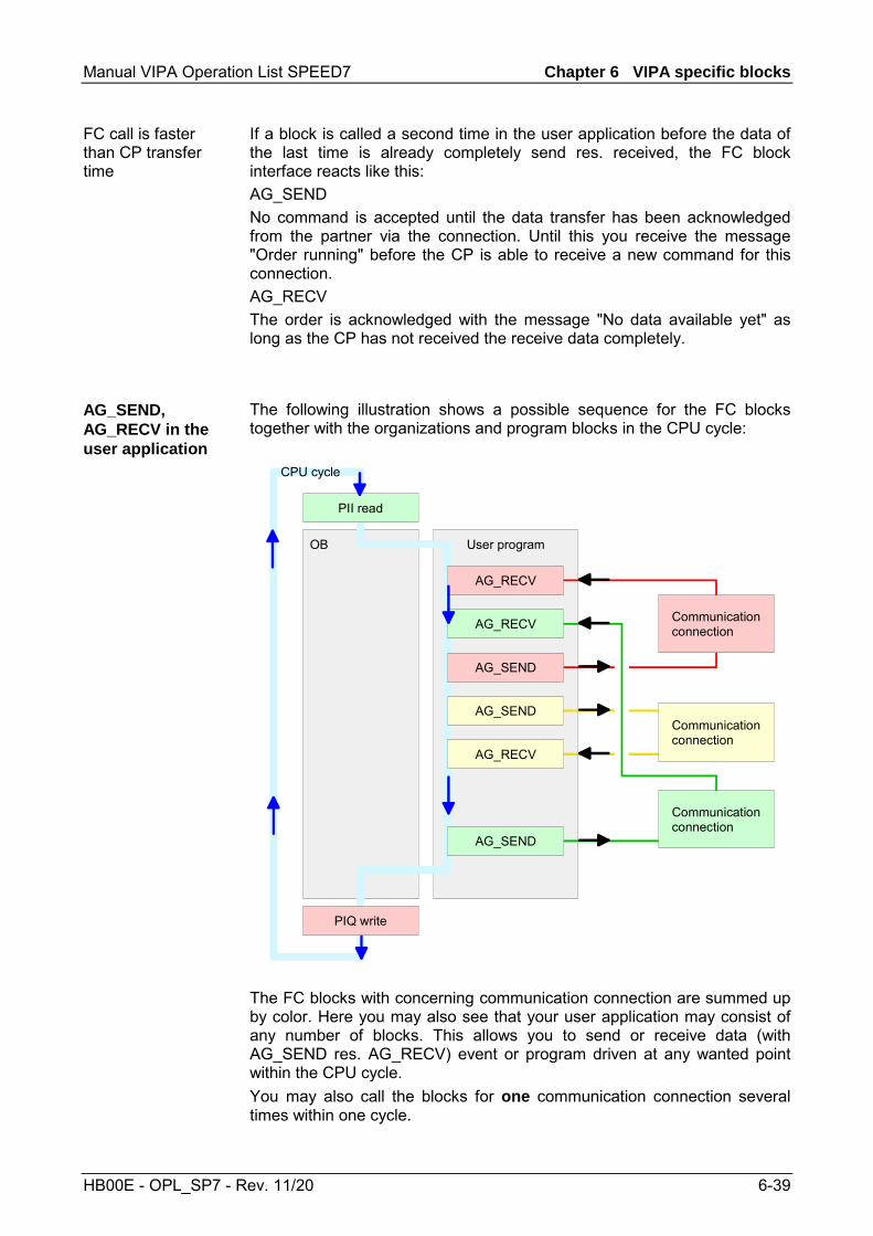
Manual VIPA Operation List SPEED7 Chapter 6 VIPA specific blocks
HB00E - OPL_SP7 - Rev. 11/20 6-39
If a block is called a second time in the user application before the data of the last time is already completely send res. received, the FC block interface reacts like this: AG_SEND No command is accepted until the data transfer has been acknowledged from the partner via the connection. Until this you receive the message "Order running" before the CP is able to receive a new command for this connection. AG_RECV The order is acknowledged with the message "No data available yet" as long as the CP has not received the receive data completely.
The following illustration shows a possible sequence for the FC blocks together with the organizations and program blocks in the CPU cycle:
OB
Communicationconnection
Communicationconnection
Communicationconnection
PIQ write
PII read
User program
AG_SEND
AG_RECV
AG_RECV
AG_SEND
AG_SEND
AG_RECV
CPU cycle
The FC blocks with concerning communication connection are summed up by color. Here you may also see that your user application may consist of any number of blocks. This allows you to send or receive data (with AG_SEND res. AG_RECV) event or program driven at any wanted point within the CPU cycle. You may also call the blocks for one communication connection several times within one cycle.
FC call is faster than CP transfer time
AG_SEND, AG_RECV in the user application
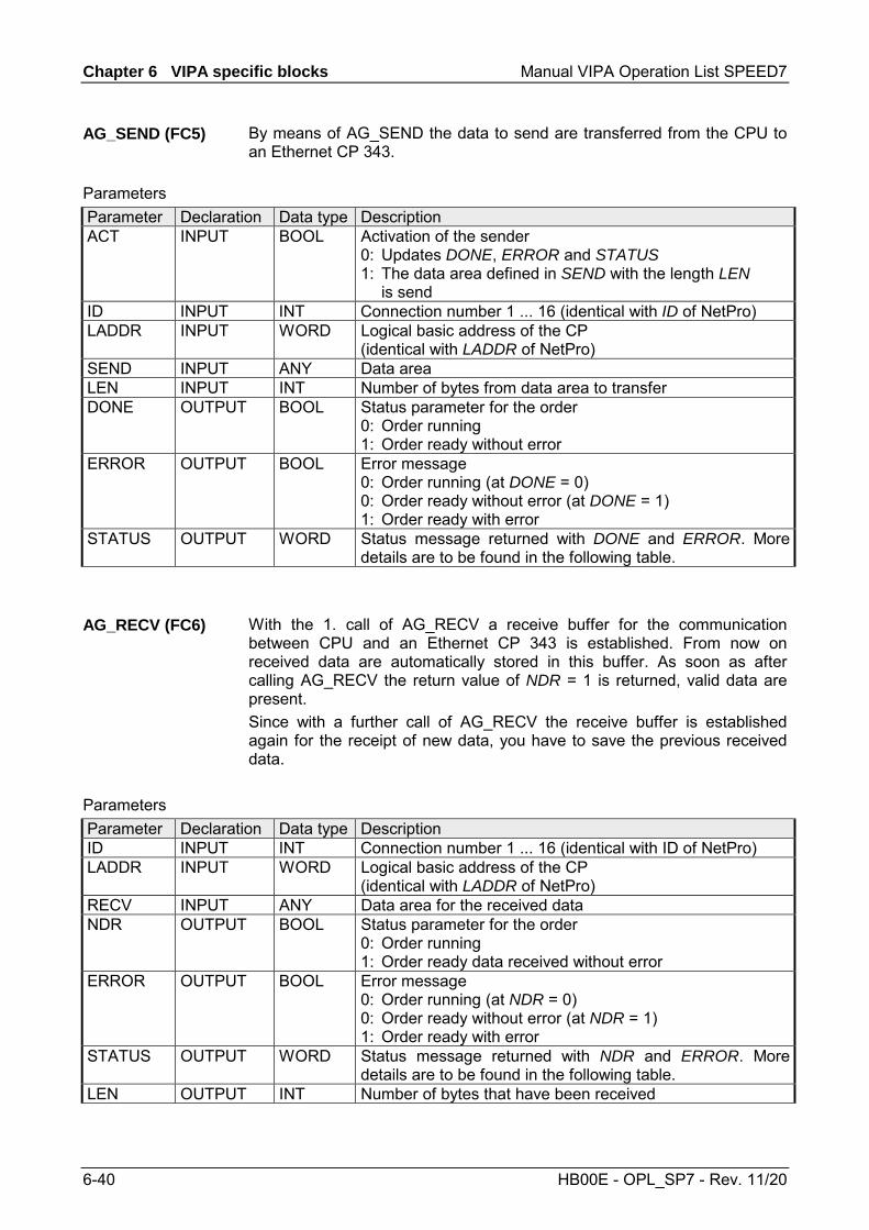
Chapter 6 VIPA specific blocks Manual VIPA Operation List SPEED7
6-40 HB00E - OPL_SP7 - Rev. 11/20
By means of AG_SEND the data to send are transferred from the CPU to an Ethernet CP 343.
Parameter Declaration Data type Description ACT INPUT BOOL Activation of the sender
0: Updates DONE, ERROR and STATUS 1: The data area defined in SEND with the length LEN is send
ID INPUT INT Connection number 1 ... 16 (identical with ID of NetPro) LADDR INPUT WORD Logical basic address of the CP
(identical with LADDR of NetPro) SEND INPUT ANY Data area LEN INPUT INT Number of bytes from data area to transfer DONE OUTPUT BOOL Status parameter for the order
0: Order running 1: Order ready without error
ERROR OUTPUT BOOL Error message 0: Order running (at DONE = 0) 0: Order ready without error (at DONE = 1) 1: Order ready with error
STATUS OUTPUT WORD Status message returned with DONE and ERROR. More details are to be found in the following table.
With the 1. call of AG_RECV a receive buffer for the communication between CPU and an Ethernet CP 343 is established. From now on received data are automatically stored in this buffer. As soon as after calling AG_RECV the return value of NDR = 1 is returned, valid data are present. Since with a further call of AG_RECV the receive buffer is established again for the receipt of new data, you have to save the previous received data.
Parameter Declaration Data type Description ID INPUT INT Connection number 1 ... 16 (identical with ID of NetPro) LADDR INPUT WORD Logical basic address of the CP
(identical with LADDR of NetPro) RECV INPUT ANY Data area for the received data NDR OUTPUT BOOL Status parameter for the order
0: Order running 1: Order ready data received without error
ERROR OUTPUT BOOL Error message 0: Order running (at NDR = 0) 0: Order ready without error (at NDR = 1) 1: Order ready with error
STATUS OUTPUT WORD Status message returned with NDR and ERROR. More details are to be found in the following table.
LEN OUTPUT INT Number of bytes that have been received
AG_SEND (FC5)
Parameters
AG_RECV (FC6)
Parameters

Manual VIPA Operation List SPEED7 Chapter 6 VIPA specific blocks
HB00E - OPL_SP7 - Rev. 11/20 6-41
The following table shows all messages that can be returned by the Ethernet CP 343 after a SEND res. RECV command. A "-" means that this message is not available for the concerning SEND res. RECV command.
DONE (SEND)
NDR (RECV)
ERROR STATUS Description
1 - 0 0000h Order ready without error. - 1 0 0000h New data received without error. 0 - 0 0000h No order present. - 0 0 8180h No data available yet. 0 0 0 8181h Order running 0 0 1 8183h No CP project engineering for this order. 0 - 1 8184h System error - 0 1 8184h System error (destination data area failure). 0 - 1 8185h Parameter LEN exceeds source area SEN.D 0 1 8185h Destination buffer (RECV) too small. 0 0 1 8186h Parameter ID invalid (not within 1 ...16). 0 - 1 8302h No receive resources at destination station, receive
station is not able to process received data fast enough res. has no receive resources reserved.
0 - 1 8304h The connection is not established. The send command shouldn’t be sent again before a delay time of >100ms.
- 0 1 8304h The connection is not established. The receive command shouldn’t be sent again after a delay time of >100ms.
0 - 1 8311h Destination station not available under the defined Ethernet address.
0 - 1 8312h Ethernet error in the CP. 0 1 8F22h Source area invalid, e.g. when area in DB not present
Parameter LEN < 0 - 0 1 8F23h Source area invalid, e.g. when area in DB not present
Parameter LEN < 0 0 - 1 8F24h Range error at reading a parameter. - 0 1 8F25h Range error at writing a parameter. 0 - 1 8F28h Orientation error at reading a parameter. - 0 1 8F29h Orientation error at writing a parameter. - 0 1 8F30h Parameter is within write protected 1. recent data block - 0 1 8F31h Parameter is within write protected 2. recent data block 0 0 1 8F32h Parameter contains oversized DB number. 0 0 1 8F33h DB number error 0 0 1 8F3Ah Area not loaded (DB)
continued...
DONE, ERROR, STATUS

Chapter 6 VIPA specific blocks Manual VIPA Operation List SPEED7
6-42 HB00E - OPL_SP7 - Rev. 11/20
... continue DONE, ERROR, STATUS DONE
(SEND) NDR
(RECV) ERROR STATUS Description
0 - 1 8F42h Acknowledgement delay at reading a parameter from peripheral area.
- 0 1 8F43h Acknowledgement delay at writing a parameter from peripheral area.
0 - 1 8F44h Address of the parameter to read locked in access track- 0 1 8F45h Address of the parameter to write locked in access
track 0 0 1 8F7Fh Internal error e.g. invalid ANY reference e.g. parameter
LEN = 0. 0 0 1 8090h Module with this module start address not present or
CPU in STOP. 0 0 1 8091h Module start address not within double word grid. 0 0 1 8092h reference contains type setting unequal BYTE. - 0 1 80A0h Negative acknowledgement at reading the module. 0 0 1 80A4h reserved 0 0 1 80B0h Module doesn’t recognize record set. 0 0 1 80B1h The length setting (in parameter LEN) is invalid. 0 0 1 80B2h reserved 0 0 1 80C0h Record set not readable. 0 0 1 80C1h The set record set is still in process. 0 0 1 80C2h Order accumulation. 0 0 1 80C3h The operating sources (memory) of the CPU are
temporarily occupied. 0 0 1 80C4h Communication error (occurs temporarily; a repetition in
the user application is reasonable). 0 0 1 80D2h Module start address is wrong.
At a reboot of the CP, the output parameters are set as follows: • DONE = 0 • NDR = 0 • ERROR = 0 • STATUS = 8180h (at AG_RECV)
STATUS = 8181h (at AG_SEND)
Status parameter at reboot

Manual VIPA Operation List SPEED7 Chapter 6 VIPA specific blocks
HB00E - OPL_SP7 - Rev. 11/20 6-43
FC 10 - AG_CNTRL - CP 343 communication
The connections of the Ethernet CP 343 may be diagnosed and initialized by means of the VIPA FC 10. The following jobs may be executed by parameterizable commands: • Reading connection information • Resetting configured connections The commands of this block are permitted only for SEND/RECV connections based on the ISO/RFC/TCP and UDP protocols.
The following diagram shows a typical sequence of AG_CNTRL. Here it is shown how the connection status is initially queried and then, in a second job, how the connection termination is triggered with the rest command.
User program(CPU cycle)
Status query with AG_CNTRL:ACT: 0-1; CMD = 1, ID = 1 (connection)
AG_CNTRL (status query)
Status connection ID 1 1)
Reset with AG_CNTRL:ACT: 0-1; CMD = 2, ID = 1 (connection)
AG_CNTRL (Reset)
Acknowledgement of jobacceptance:RESULT1: "Connection establishment triggered" 1)
Status query for connection 1is acknowledged
Reset request active:(Bit 15 in RESULT1 is set)
Connection is terminatedand reinitialized:(Bit 15 in RESULT1 remains set)
Entry in diagnostic buffer
Status query with AG_CNTRL:ACT: 0-1; CMD = 1, ID = 1 (connection)
AG_CNTRL (status query)
Status connection ID1 1)
Acknowledgement: RESULT1: B095h "Reset was executed"
Status query is acknow-ledged then the reset ID (Bit 15 in Result 1) is cleared
Ethernet-CP
Time Time
Abort and reestablisha connection
1) Parameter transfer DONE, ERROR, STATUS and RESULT1/2
Description
FC 10 in the user program
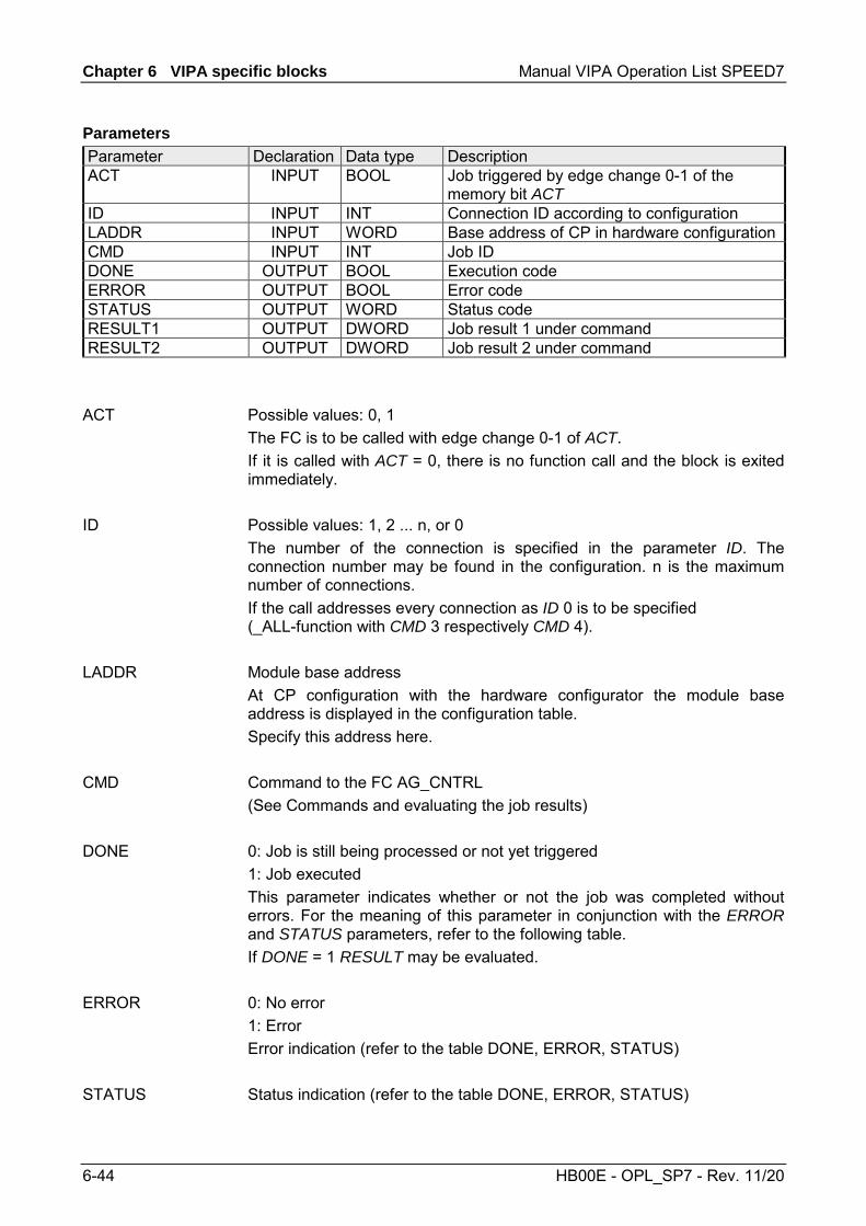
Chapter 6 VIPA specific blocks Manual VIPA Operation List SPEED7
6-44 HB00E - OPL_SP7 - Rev. 11/20
Parameter Declaration Data type Description ACT INPUT BOOL Job triggered by edge change 0-1 of the
memory bit ACT ID INPUT INT Connection ID according to configuration LADDR INPUT WORD Base address of CP in hardware configurationCMD INPUT INT Job ID DONE OUTPUT BOOL Execution code ERROR OUTPUT BOOL Error code STATUS OUTPUT WORD Status code RESULT1 OUTPUT DWORD Job result 1 under command RESULT2 OUTPUT DWORD Job result 2 under command
Possible values: 0, 1 The FC is to be called with edge change 0-1 of ACT. If it is called with ACT = 0, there is no function call and the block is exited immediately. Possible values: 1, 2 ... n, or 0 The number of the connection is specified in the parameter ID. The connection number may be found in the configuration. n is the maximum number of connections. If the call addresses every connection as ID 0 is to be specified (_ALL-function with CMD 3 respectively CMD 4). Module base address At CP configuration with the hardware configurator the module base address is displayed in the configuration table. Specify this address here. Command to the FC AG_CNTRL (See Commands and evaluating the job results) 0: Job is still being processed or not yet triggered 1: Job executed This parameter indicates whether or not the job was completed without errors. For the meaning of this parameter in conjunction with the ERROR and STATUS parameters, refer to the following table. If DONE = 1 RESULT may be evaluated. 0: No error 1: Error Error indication (refer to the table DONE, ERROR, STATUS) Status indication (refer to the table DONE, ERROR, STATUS)
Parameters
ACT
ID
LADDR
CMD
DONE
ERROR
STATUS

Manual VIPA Operation List SPEED7 Chapter 6 VIPA specific blocks
HB00E - OPL_SP7 - Rev. 11/20 6-45
Information returned according to the command sent to the FC AG_CNTRL (See commands and evaluating the job results). The following table shows the messages that may be returned by the Ethernet-CP 343 after an AG_CNTRL call. Additional the command results in the parameters RESULT1 and RESULT2 are to be evaluated.
DONE ERROR STATUS Description 1 0 0000h Job executed without error 0 0 0000h No job executing 0 0 8181h Job active, the block call is to be repeated with the same
parameters until DONE or ERROR is returned. 0 1 8183h There is no CP configuration for this job or the service has not yet
started in the Ethernet-CP 343. 0 1 8186h Parameter ID is invalid. The permitted ID depends on the
selected command. 0 1 8187h Parameter CMD is invalid 0 1 8188h Sequence error in the ACT control 0 1 8090h Module with this address does not exist or CPU in STOP. 0 1 8091h The module base address is not on a double-word boundary. 0 1 80B0h The module does not recognize the record set. 0 1 80C0h The record set cannot be read. 0 1 80C1h The specified record set is currently being processed. 0 1 80C2h There are too many jobs pending. 0 1 80C3h CPU resources (memory) occupied. 0 1 80C4h Communication error (error occurs temporarily; it is usually best
to repeat the job in the user program). 0 1 80D2h The module base address is incorrect.
The output parameters are set to the following values during a restart of the CP: • DONE = 0 • NDR = 0 • ERROR = 8180h (at AG_RECV)
ERROR = 8181h (at AG_SEND)
Note! Please consider the block may only be called with new parameters if a job started before was just ended with DONE = 1.
RESULT1/2
DONE, ERROR, STATUS
Status parameter at cold restart
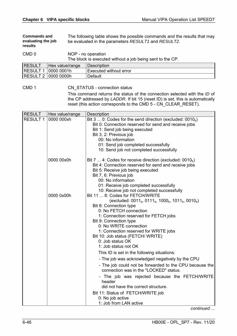
Chapter 6 VIPA specific blocks Manual VIPA Operation List SPEED7
6-46 HB00E - OPL_SP7 - Rev. 11/20
The following table shows the possible commands and the results that may be evaluated in the parameters RESULT1 and RESULT2. NOP - no operation The block is executed without a job being sent to the CP.
RESULT Hex value/range Description RESULT 1 0000 0001h Executed without error RESULT 2 0000 0000h Default
CN_STATUS - connection status This command returns the status of the connection selected with the ID of the CP addressed by LADDR. If bit 15 (reset ID) is set, this is automatically reset (this action corresponds to the CMD 5 - CN_CLEAR_RESET).
RESULT Hex value/range Description RESULT 1 0000 000xh
0000 00x0h 0000 0x00h
Bit 3 ... 0: Codes for the send direction (excluded: 0010b) Bit 0: Connection reserved for send and receive jobs Bit 1: Send job being executed Bit 3, 2: Previous job 00: No information 01: Send job completed successfully 10: Send job not completed successfully Bit 7 ... 4: Codes for receive direction (excluded: 0010b) Bit 4: Connection reserved for send and receive jobs Bit 5: Receive job being executed Bit 7, 6: Previous job 00: No information 01: Receive job completed successfully 10: Receive job not completed successfully Bit 11 ... 8: Codes for FETCH/WRITE
(excluded: 0011b, 0111b, 1000b, 1011b, 0010b) Bit 8: Connection type 0: No FETCH connection 1: Connection reserved for FETCH jobs Bit 9: Connection type 0: No WRITE connection 1: Connection reserved for WRITE jobs Bit 10: Job status (FETCH/ WRITE) 0: Job status OK 1: Job status not OK This ID is set in the following situations:
- The job was acknowledged negatively by the CPU - The job could not be forwarded to the CPU because the
connection was in the "LOCKED" status. - The job was rejected because the FETCH/WRITE
header did not have the correct structure.
Bit 11: Status of FETCH/WRITE job 0: No job active 1: Job from LAN active
continued ...
Commands and evaluating the job results
CMD 0
CMD 1

Manual VIPA Operation List SPEED7 Chapter 6 VIPA specific blocks
HB00E - OPL_SP7 - Rev. 11/20 6-47
... continue RESULT Hex value/range Description 0000 x000h Bit 15 ... 12: General CP information
(excluded: 0011b, 1011b) Bit 13, 12: Connection status (only available for SEND/RECV connections based on the ISO/RFC/TCP protocols; with UDP, the corresponding internal information is output) 00: Connection is terminated 01: Connection establishment active 10: Connection termination active 11: Connection is established Bit 14: CP information 0: CP in STOP 1: CP in RUN Bit 15: Reset ID 0: FC 10 has not yet reset a connection or the reset ID was cleared. 1: The FC 10 has executed a connection reset
xxxx 0000h Bit 31 ... 16: Reserved for later expansions RESULT 2 0000 0000h Reserved for later expansions
CN_RESET - connection reset This command resets the connection selected with the ID of the CP addressed by LADDR. Resetting the connection means that a connection is aborted and established again (active ore passive depending on the configuration). An entry is also generated in the diagnostic buffer in which the job result may be found.
RESULT Hex value/range Description RESULT 1 0000 0001h
The reset job was transferred to the CP successfully. The connection abort and subsequent connection establishment were triggered.
0000 0002h The reset job could not be transferred to the CP because the service was not started on the CP (for example CP in STOP).
RESULT 2 0000 0000h Default
CMD 2
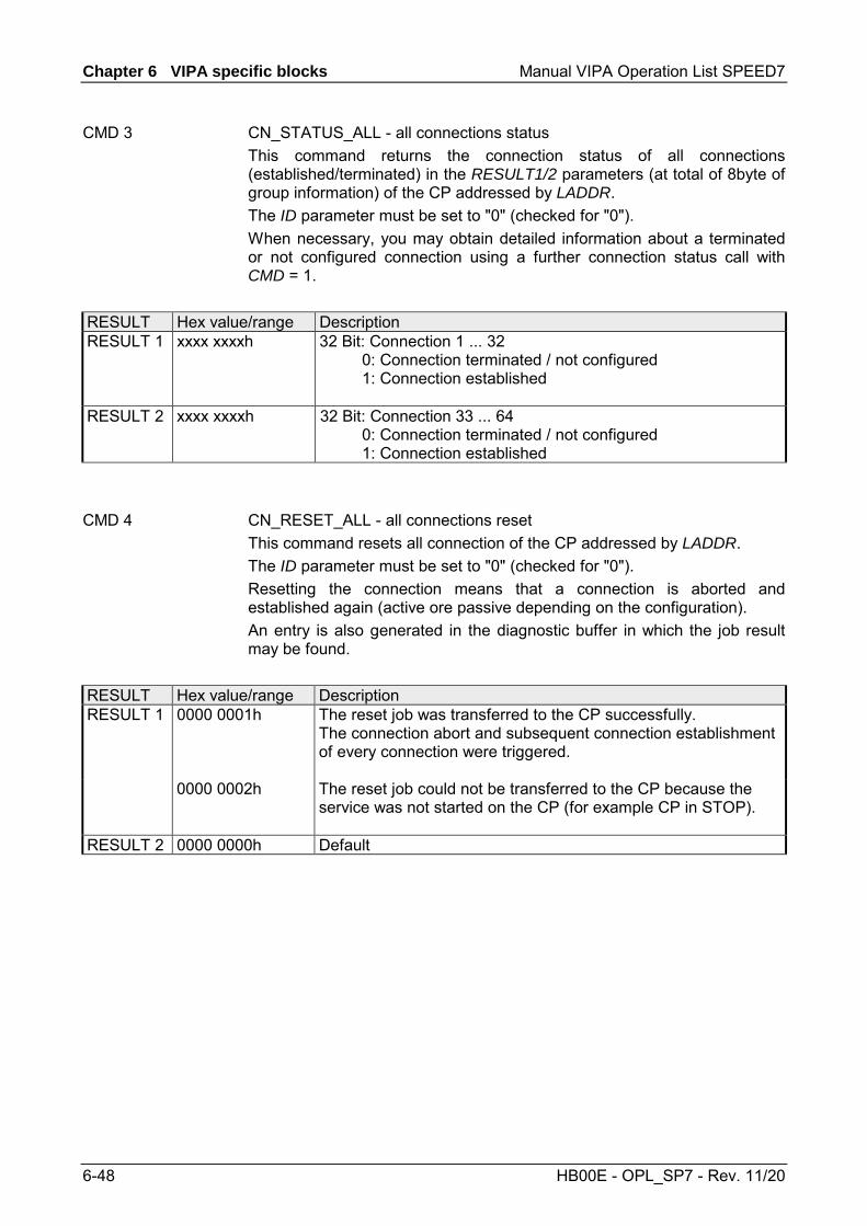
Chapter 6 VIPA specific blocks Manual VIPA Operation List SPEED7
6-48 HB00E - OPL_SP7 - Rev. 11/20
CN_STATUS_ALL - all connections status This command returns the connection status of all connections (established/terminated) in the RESULT1/2 parameters (at total of 8byte of group information) of the CP addressed by LADDR. The ID parameter must be set to "0" (checked for "0"). When necessary, you may obtain detailed information about a terminated or not configured connection using a further connection status call with CMD = 1.
RESULT Hex value/range Description RESULT 1 xxxx xxxxh
32 Bit: Connection 1 ... 32 0: Connection terminated / not configured 1: Connection established
RESULT 2 xxxx xxxxh 32 Bit: Connection 33 ... 64 0: Connection terminated / not configured 1: Connection established
CN_RESET_ALL - all connections reset This command resets all connection of the CP addressed by LADDR. The ID parameter must be set to "0" (checked for "0"). Resetting the connection means that a connection is aborted and established again (active ore passive depending on the configuration). An entry is also generated in the diagnostic buffer in which the job result may be found.
RESULT Hex value/range Description RESULT 1 0000 0001h
The reset job was transferred to the CP successfully. The connection abort and subsequent connection establishment of every connection were triggered.
0000 0002h The reset job could not be transferred to the CP because the service was not started on the CP (for example CP in STOP).
RESULT 2 0000 0000h Default
CMD 3
CMD 4

Manual VIPA Operation List SPEED7 Chapter 6 VIPA specific blocks
HB00E - OPL_SP7 - Rev. 11/20 6-49
CN_CLEAR_RESET - Clear the reset ID This command resets the reset ID (bit 15 in RESULT1) for the connection selected with the ID of the CP addressed by LADDR. This job executes automatically when the connection status is read (CMD = 1); the separate job described here is therefore only required in special situations.
RESULT Hex value/range Description RESULT 1 0000 0001h
The clear job was transferred to the CP successfully.
0000 0002h The clear job could not be transferred to the CP because the service was not started on the CP (for example CP in STOP).
RESULT 2 0000 0000h Default
CN_DISCON - connection disconnect This command resets the connection, which was selected by ID and LADDR. The reset is executed by means of aborting the connection. Possibly in the stack stored data are lost without any instructions. After that no further connection is automatically established. The connection may again be established by the control job CN_STARTCON. An entry is also generated in the diagnostic buffer in which the job result may be found.
RESULT Hex value/range Description RESULT 1 0000 0001h
The job was transferred to the CP successfully. The connection abort was triggered.
0000 0002h This job could not be transferred to the CP because the service was not started on the CP (for example CP in STOP).
RESULT 2 0000 0000h Default
CN_STARTCON - start connection This command establishes a connection, which was selected by ID and LADDR and aborted by the control job CN_DISCON before. An entry is also generated in the diagnostic buffer in which the job result may be found.
RESULT Hex value/range Description RESULT 1 0000 0001h
The job was transferred to the CP successfully. The connection abort was triggered.
0000 0002h This job could not be transferred to the CP because the service was not started on the CP (for example CP in STOP).
RESULT 2 0000 0000h Default
CMD 5
CMD 6
CMD 7

Chapter 6 VIPA specific blocks Manual VIPA Operation List SPEED7
6-50 HB00E - OPL_SP7 - Rev. 11/20
FC 200 - IBS_INIT
This FC synchronizes the INTERBUS master with the CPU and checks the number of connected in- and output bytes as well as the bus structure.
Parameter Declaration Data type Description WORK_DB IN BLOCK_DB INTERBUS work DB LADDR IN INT Logical base address of INTERBUS master MODE IN INT Mode for start-up WAIT_TIME IN S5TIME Wait time for INTERBUS Master
acknowledgement TIMER_NO IN INT Timer number for wait time SERVICE_DB_SEND IN INT DB number with services SERVICE_DB_REC IN INT DB number for INTERBUS master
acknowledgement NO_OF_SERVICES IN Word Number of services to be processed starting
at FIRST_SERVICE READ_DIAG IN BOOL Structure diagnostic data RET_VAL OUT WORD Return value on error FIRST_SERVICE IN_OUT BYTE Number of 1. service of the service DB to be
processed Set the work DB for the wanted master. Set the address (Logical Address) from where on the register of the masters is to be mapped into the CPU. At start-up of the CPU, the INTERBUS master are mapped into the I/O address range of the CPU with the following formula if no hardware configuration is present:
Start address = 256⋅ (Slot-101)+2048 The slot numbering at the SPEED-Bus starts with 101 at the left side of the CPU and ascends from the right to the left. For example, the 1. slot has the address 2048, the 2. the address 2304 etc.. This parameter allows you to preset 3 modes for start-up: 0 = Calculate address only 1 = Calculate address and wait for Ready of the INTERBUS master 2 = Calculate address, parameterize and start INTERBUS master 3 = Calculate address and automatically start of INTERBUS after auto-
configuration via switch
Description
Parameters
WORK_DB
LADDR
MODE

Manual VIPA Operation List SPEED7 Chapter 6 VIPA specific blocks
HB00E - OPL_SP7 - Rev. 11/20 6-51
Here you may define a waiting period with the according timer by setting WAIT_TIME and TIMER-NO that the CPU has to wait for a master acknowledgement after a service command.
Note! Please regard at setting a timer number. That always 2 sequential timers are used: Timer 1: TIMER_NO, Timer 2: TIMER_NO + 1
Enter the DB that contains the according service instructions via SERVICE_DB_SEND. In SERVICE_DB_REC the INTERBUS master returns the receipt. More details about the structure of the service DB may be found on the following page at "FC 202 Process service". In NO_OF_SERVICES you enter the number of services that have to be processed in the service DB after the 1. service that you set in FIRST_SERVICE. This parameter allows you to influence the structure of a diagnosis: 0 = Normal diagnosis 1 = Extended diagnosis In case of an error, RET_VAL may contain the following error messages: 1 = Waiting period for master receipt (READY) exceeded - master not ready 2 = Execution of a service to process has failed
WAIT_TIME TIMER_NO
SERVICE_DB_SEND SERVICE_DB_REC
NO_OF_SERVICES FIRST_SERVICE
READ_DIAG
RET_VAL

Chapter 6 VIPA specific blocks Manual VIPA Operation List SPEED7
6-52 HB00E - OPL_SP7 - Rev. 11/20
FC 202 - IBS_SERVICE
This function block allows you to transfer services to the INTERBUS master and to react to the according acknowledgements. For the INTERBUS master card USC4-1 from Phoenix Contact is deployed as INTERBUS hardware platform, please also refer to the extensive documentation (IBS SYS FW G4 UM) from Phoenix Contact for the description of the INTERBUS services and INTERBUS error messages.
Parameter Declaration Data type Description WORK_DB IN BLOCK_DB INTERBUS work DB SERVICE_DB_SEND IN INT DB number with services SERVICE_DB_REC IN INT DB number for INTERBUS master
acknowledgement FIRST_SERVICE IN Byte Number of 1. service of the service DB to be
processed START IN_OUT BOOL Start bit of the function ERROR IN_OUT BOOL Error bit of the function
Set the work DB for the wanted master. Enter the DB that contains the according service instructions via SERVICE_DB_SEND. In SERVICE_DB_REC the INTERBUS master returns the receipt. Enter the position of the first service within the send DB.
Note! Please regard that you have to enter the number of services that are to be transferred after FIRST_SERVICE in the work DB before calling the FC 202.
Description
Parameters
WORK_DB
SERVICE_DB_SEND SERVICE_DB_REC
FIRST_SERVICE

Manual VIPA Operation List SPEED7 Chapter 6 VIPA specific blocks
HB00E - OPL_SP7 - Rev. 11/20 6-53
You may enter a max. of 30 services in one DB. Up to 2 DBs, 60 services in total, may be transferred to the INTERBUS master at every FC call.
DBB Contents 0 ... 69 Record set 1
70 ... 139 Record set 2 . . .
. . .
2030 ... 2099 Record set 30 2100 Instruction number 2. DB
Structure record set
DBW Contents 0 Send length (Number of bytes to be send) 1 Code number of service 2 Parameter count
3 ... 68 Parameter By setting the start bit, the services are transferred to the INTERBUS master and started. In case of an error, the Start bit is set back and the error bit is set. Additionally, the number of the service that has been processed when the error occurred is entered in the DBB113 of the work DB. The error code is displayed in DBB112. The following error codes may occur: 2 = Error of the master at reading data from SSGI Box 3 = Return code of the acknowledgement not valid 4 = Service could not be processed 5 = No acknowledgement within waiting period
Note! If DBB112 contains the error code 4, further error codes are entered into DBW114 and 116 of the work DB. Information about these error codes is to be found in the documentation of the services (IBS SYS FW G4 UM) from Phoenix Contact.
Structure service DB
START
ERROR

Chapter 6 VIPA specific blocks Manual VIPA Operation List SPEED7
6-54 HB00E - OPL_SP7 - Rev. 11/20
FC 204 - IBS_LOOP, FC 205 - IBS_CYCLE
The FC 204 serves the exchange of in- and output data between INTERBUS master and CPU. This block always awaits an acknowledgement of the master after a data request and continues the cycle processing only after reception. If this block influences the cycle processing of the CPU too much, you should use the FC 205 Asynchr_Cycle instead. In opposite to the FC 204 this does not wait for an acknowledgement but continues cycle processing after data request. Occurring error messages are to be found after block processing in the work DB in DBW150.
Parameter Declaration Data type Description WORK_DB IN BLOCK_DB INTERBUS work DB RW_MODE IN INT Mode of Read/Write (0=R/W, 1=R, 2=W) OPERATION_MODE
IN INT Operation mode (0=asynchr., 1=asynchr. with consistency)
TYP_OUT IN INT Data type of INTERBUS slave out data (0=DB, 1=MB, 2=OB)
TYP_IN IN INT Data type of INTERBUS slave in data (0=DB, 1=MB, 2=IB)
START IN_OUT BOOL Start bit of the function
Set the work DB for the wanted master. The following modes are available: 0 = Read input data and write output data 1 = Read input data only 2 = Write output data only The transfer may happen with the following operating modes: 0 = Asynchronous data exchange without consistency lock
In this operating mode it may happen that read res. written data is not out of the same INTERBUS cycle and is therefore inconsistent.
1 = Asynchronous data exchange with consistency lock Here the CPU sets a bit for read/write request. As soon as the next INTERBUS cycle is finished and data is ready, the INTERBUS master sets a release bit. The CPU transfers its data and signalizes the end of data transfer by setting back the request. Now the INTERBUS master deletes the release and continues the INTERBUS cycle.
Description
Parameters
WORK_DB
RW_MODE
OPERATION_MODE

Manual VIPA Operation List SPEED7 Chapter 6 VIPA specific blocks
HB00E - OPL_SP7 - Rev. 11/20 6-55
This parameter defines the type of the data area where the I/O data of connected INTERBUS slaves is stored. The following types are available: 0 = DB (data block) 1 = MB (bit memory byte) 2 = I/O range of the CPU
By setting the Start bit, the FC is executed. The start is set back again in the block.
During the execution of the block, the following errors that are stored in DBW 150 of the work DB may occur: 1 = Data release of the master missing - read inputs 2 = Data release of the master missing - write outputs 3 = Data release of the masters is not deleted
TYP_OUT TYP_IN
START
Error message

Chapter 6 VIPA specific blocks Manual VIPA Operation List SPEED7
6-56 HB00E - OPL_SP7 - Rev. 11/20
FC 206 - IBS_IRQ
At deployment of the FC 206, the data transfer of the in- and output data between CPU and INTERBUS master is controlled via interrupts. As soon as the INTERBUS master has provided its data, it initializes an interrupt. The CPU transfers its data and also signalizes the end of the data transfer via an interrupt. Now the INTERBUS master continues the INTERBUS cycle.
Parameter Declaration Data type Description WORK_DB IN BLOCK_DB INTERBUS work DB RW_MODE IN INT Mode of R/W (0=R/W, 1=R, 2=W) TYP_OUT IN INT Data type of INTERBUS slave out data
(0=DB, 1=MB, 2=OB) TYP_IN IN INT Data type of INTERBUS slave in data
(0=DB, 1=MB, 2=IB)
Set the work DB for the wanted master. The following modes are available: 0 = Read input data and write output data 1 = Read input data only 2 = Write output data only This parameter defines the type of the data area where the I/O data of connected INTERBUS slaves is stored. The following types are available: 0 = DB (data block) 1 = MB (bit memory byte) 2 = I/O range of the CPU
Description
Parameters
WORK_DB
RW_MODE
TYP_OUT TYP_IN
Manual VIPA Operation List SPEED7 Chapter 6 VIPA specific blocks
HB00E - OPL_SP7 - Rev. 11/20 6-57
FC 207 - IBS_PCP
This function block allows you to transfer PCP services to the INTERBUS master and to react to the according acknowledgements. The Peripherals Communication Protocol (PCP) serves the transmission of instructions and parameters to connected slaves and the reception of acknowledgements and data of the slaves. Information about the services is to be found in the documentation of the services, available via our application department.
Parameter Declaration Data type Description WORK_DB IN BLOCK_DB INTERBUS work DB SERVICE_DB_SEND IN INT DB number with services SERVICE_DB_REC IN INT DB number for INTERBUS master
acknowledgement FIRST_SERVICE IN Byte Number of 1. service of the service DB to be
processed START IN_OUT BOOL Start bit of the function ERROR IN_OUT BOOL Error bit of the function
Set the work DB for the wanted master. Enter the DB that contains the according PCP service instructions via SERVICE_DB_SEND. In SERVICE_DB_REC the slaves return the receipt. Enter the position of the first PCP service within the send.
Note! Please regard that you have to enter the number of services that are to be transferred after FIRST_SERVICE in the work DB before calling the FC 207.
Description
Parameters
WORK_DB
SERVICE_DB_SEND SERVICE_DB_REC
FIRST_SERVICE

Chapter 6 VIPA specific blocks Manual VIPA Operation List SPEED7
6-58 HB00E - OPL_SP7 - Rev. 11/20
You may enter a max. of 30 PCP services in one DB. Up to 2 DBs, 60 PCP services in total, may be transferred to the INTERBUS master at every FC call.
DBB Content 0 ... 69 Record set 1
70 ... 139 Record set 2 . . .
. . .
2030 ... 2099 Record set 30 2100 Sequence number of 2. DB
Structure record set
DBW Content 0 Send length (Number of bytes to be send) 1 Code number of PCP service 2 Parameter count
3 ... 68 Parameter
By setting the start bit, the PCP services are transferred to the INTERBUS master and started. In case of an error, the start bit is set back and the error bit is set. Additionally, the number of the PCP service that has been processed when the error occurred is entered in the DBB193. The following error codes may be entered into DBB192: 2 = Error of the master at reading data from SSGI Box 3 = Return code of the acknowledgement not valid 4 = Service could not be processed 5 = No acknowledgement within waiting period
Note! If ERROR contains the error code 4, further error codes are entered into DBW194 and 196 of the work DB. Information about these error codes is to be found in the documentation of the error codes, available via our application department.
Structure service DB
START
ERROR

Manual VIPA Operation List SPEED7 Chapter 6 VIPA specific blocks
HB00E - OPL_SP7 - Rev. 11/20 6-59
FC 208 - IBS_DIAG
Via this function block you may read diagnostic data from the master res. slave in case of an INTERBUS breakdown. Here you may also define the reboot operating mode of the INTERBUS master after breakdown.
Parameter Declaration Data type Description WORK_DB IN BLOCK_DB INTERBUS work DB ACTIVATE IN INT Manual error acknowledgement AUTO_START IN INT Automatic error acknowledgement RUN OUT Byte INTERBUS at status RUN PERIPHERAL_ERROR OUT BOOL Error at periphery BUS_QUALITY OUT BOOL Sporadic bus errors occurred DETECTION OUT BOOL Internal error is searched BUSY_STATE OUT BOOL Internal diagnostic function is busy
Set the work DB for the wanted master. The ACTIVATE transmission parameter of the type Boolean that you may control for example via an external caliper, allows you to reboot the INTERBUS master by setting (push button). By setting of auto-start, the INTERBUS master reboots automatically after error recovering. AUTO-START has always preference before ACTIVATE. This parameter shows the status of the INTERBUS master: 0 = INTERBUS master is in STOP 1 = INTERBUS master is in RUN If a periphery error occurs, the INTERBUS master announces PF = 1. At PF = 0 no periphery error occurred. In case of an error you will see the number of the causing slave in the work DB starting with 1. This parameter displays information about the transfer quality within the INTERBUS. As soon as the bit is set by the INTERBUS master, some single transmission interferences have occurred. Please check the transfer routes with according diagnosis software. The parameter DETECTION is set by the INTERBUS master when the internal error detection is running. When the error detection is finished, DETECTION is set back again. When a diagnosis is executed within the diagnosis block, BUSY_STATE is set. As soon as diagnosis data are available, the block sets BUSY_STATE back again.
Description
Parameters
WORK_DB
ACTIVATE AUTO_START
RUN
PERIPHERAL_ ERROR
BUS_QUALITY
DETECTION
BUSY_STATE
Chapter 6 VIPA specific blocks Manual VIPA Operation List SPEED7
6-60 HB00E - OPL_SP7 - Rev. 11/20
SFB 7 - uS_TIME and SFC 53 - uS_TICK - Time measurement
This block allows you to read the µs ticker integrated in the SPEED7-CPU. The µs ticker is a 32bit µs time counter that starts at every reboot with 0 and counts to 232-1µs. At overflow the counter starts again with 0. With the help of the difference creation of the RETVAL results of 2 SFC 53 calls before and after an application you may thus evaluate the runtime of the application in µs. Status µs system time Start-up Starts with 0 and is permanently updated RUN is permanently updated STOP is stopped (time cannot be read) Reboot (Reset) Starts again with 0
Name Declaration Type Comment RETVAL OUT DINT System time in µs
The parameter RETVAL contains the read system time in the range of 0 ... 232-1µs.
In opposite to the SFC 53, the SFB 7 returns the difference between two calls in µs. With RESET = 1 the current timer value is transferred to store. Another call with RESET = 0 displays the difference in µs via VALUE.
Name Declaration Type Comment RESET IN BOOL RESET=1 start timer VALUE OUT DWORD Difference in µs STORE STAT DWORD DW for 1. time
RESET = 1 transfers the current timer value to STORE. Here VALUE is not influenced. After a call with RESET = 0, VALUE returns the time difference between the two SFB 7 calls. STORE serves the storage of the 1. time value. STORE is a static variable that is located in the instance block.
SFC 53 uS_TICK
Runtime in dependence of the operating mode
Parameters
RETVAL
SFB 7 TIMEMESS
Parameters
RESET
VALUE
STORE

Manual VIPA Operation List SPEED7 Chapter 6 VIPA specific blocks
HB00E - OPL_SP7 - Rev. 11/20 6-61
SFB 239 - FUNC
With the SFB 239 FUNC system internal functions may be executed. The function is always to be called together with an instance DB.
Attention! After processing the function the CPU always automatically gets to STOP!
Parameter Declaration Data type Memory block Description REQ INPUT BOOL I, Q, M, D, L,
constant REQ = 1: Start processing
FUNC INPUT BYTE I, Q, M, D, L, constant
Function number
CODE INPUT WORD I, Q, M, D, L, constant
Safety code to ensure the functionality
PARAM INPUT ANY I, Q, M, D, L reserved BUSY OUTPUT BOOL I, Q, M, D, L reserved RET_VAL OUTPUT INT I, Q, M, D, L reserved
FUNC CODE Description
0 CA749FE0 The function copies the current loaded project in the RAM to a put memory card as s7prog.wld. With a SPEED7 CPU from VIPA the s7prog.wld is automatically read from a put memory card always after an overall reset.
1 6F33DA8B The function copies the current loaded project in the RAM to a put memory card as autoload.wld. With a SPEED7 CPU from VIPA the autoload.wld is automatically read from a put memory card always after PowerON.
Description
Parameters
Functions
Chapter 6 VIPA specific blocks Manual VIPA Operation List SPEED7
6-62 HB00E - OPL_SP7 - Rev. 11/20
SFC 193 - AI_OSZI - Oscilloscope-/FIFO function
The SFC 193 serves for controlling the oscilloscope-/FIFO function of analog input channels with this functionality. It allows to start the recording and to read the buffered data. Depending upon the parameterization there are the following possibilities: • Depending on the trigger condition at edge evaluation the monitoring of
the configured channel may be started respectively at manual operation the recording may be started.
• The recorded measuring values may be accessed by the SFC 193 as soon as the buffer is full.
• Start the recording. • Read the puffer at any time. Note! The SFC may only be called from on level of priority e.g. only from OB 1 or OB 35. The module is to be parameterized before. For starting and reading in each case the SCF 193 is to be called. The differentiation of both variants takes place in the parameter MODE.
Parameter Declaration Data type Function depending on MODE REQ IN BOOL Execute function (start/read) LADR IN WORD Base address of the module MODE IN WORD Mode (start/read) CHANNEL IN BYTE Channel to be read OFFSET IN DWORD Address offset for reading (not FIFO operation) RECORD IN ANY Memory for the read data RETVAL OUT WORD Return value (0 = OK) BUSY OUT BOOL Function is busy TIMESTAMP OUT DWORD Time stamp (only at edge evaluation) LEN INOUT DWORD Number of values to be handled per channel
Depending on the set MODE when the bit is set the recording respectively the reading may be started. Depending on the trigger condition at edge evaluation the monitoring of the configured channel may be started respectively at manual operation the recording may be started. The data are read from the module, if "read" is set at MODE. Logical basic address of the module.
Description
Oscilloscope operation
FIFO operation
Parameters
REQ
LADR

Manual VIPA Operation List SPEED7 Chapter 6 VIPA specific blocks
HB00E - OPL_SP7 - Rev. 11/20 6-63
The SFC 193 may be called with 3 different modes. The corresponding mode may be set by the parameter MODE. The configured mode is executed by setting REQ. The following values are supported: 01h: Starts recording respectively edge monitoring depending upon the
parameterization. 00h: Read data within several cycles until BUSY = 0. 80h: Read data with one access. Here the channel is specified to be read. With each call one channel may be read. This parameter is irrelevant at start calls with MODE = 01h. Offset specifies an address offset for the reading process. By this you get access to sub-ranges of the recorded data. The value for the maximum offset depends on the number of values, which were recorded per channel. OFFSET is not supported in FIFO operation. It will be ignored. Here an area for the read values to be stored at may be defined. In FIFO operation every value of the selected channel may be read, which were stored up to the time of start reading. Please regard that the buffer has a sufficient size for the data to be buffered, otherwise an error is reported. BUSY = 1 indicates that the function just processed. BUSY = 0 indicates that the function is finished. There is an internal clock with a resolution of 1µs running in every SPEED-Bus module. The returned value corresponds to the time at the SPEED-Bus module, on which the trigger event occurred. TIMESTAMP is only available at the edge triggered oscilloscope operation. It is valid as long as the job is running (RETVAL = 7xxxh) and bit 4 of byte 0 is set respectively the job has been finished without an error (RETVAL = 0000h). The length parameter realized as IN/OUT is variably interpreted depending on the selected mode at the function call. Mode: start (MODE: = 01h) At MODE = 01h this parameter may only be used at the manual oscilloscope start. Here the requested number of values per channel to be buffered may be assigned. In this mode there is no value reported by LEN. Mode: read (MODE: = 00h or 80h) At MODE = 00h respectively 80h the number of values to be read may be set. This parameter is ignored in FIFO operation. The number of the read values is returned by LEN.
MODE
CHANNEL
OFFSET
RECORD
BUSY
TIMESTAMP
LEN

Chapter 6 VIPA specific blocks Manual VIPA Operation List SPEED7
6-64 HB00E - OPL_SP7 - Rev. 11/20
In addition to the module specific error codes listed here, there general SFC error information may be returned as well.
RETVAL Description depending on the BUSY-Bit BUSY Byte
0 Bit 1, 0: 00: Call with REQ: = 0 (idle, waiting for REQ = 1) 0 01: First call with REQ: = 1 1 10: Subsequent call with REQ: = 1 1 11: Oscilloscope is just recording 1 Bit 2: REQ: = 1, but recording was not yet started.
(MODE: = 00h or MODE: = 80h) 0
Bit 3: reserved - Bit 4: Trigger event occurred and recording is just running. 1 Bit 5: Waiting for trigger event 1 Bit 7…6: reserved -
1 Bit 0: reserved - Bit 1: The number of recorded values exceeds the target area defined
by RECORD (in words). 0
Bit 2: The number of the recorded values exceeds the area defined by LEN and OFFSET.
0
Bit 3: Buffer overflow in FIFO operation. 0 Bit 7...4: 0000: Job finished without an error 0 0111: Job still running 1 1000: Job finished with error (see following table) 0
Job finished without an error
RETVAL Description depending on the BUSY-Bit BUSY 0000h Job was finished without an error. 0
Job finished with error
RETVAL Description depending on the BUSY-Bit BUSY 8002h: Oscilloscope-/FIFO function is not configured. 0 8003h: An internal error occurred - please contact VIPA. 0 8005h: The selected channel may not be read - wrong channel number. 0 8007h: The value at OFFSET exceeds the number of recorded values. 0 8090h: There is no SPEED-Bus module with this address available. 0 80D2h: LADR exceeds the peripheral address area. 0
RETVAL (Return value)
Manual VIPA Operation List SPEED7 Chapter 6 VIPA specific blocks
HB00E - OPL_SP7 - Rev. 11/20 6-65
SFC 194 - DP_EXCH
With the SFC 194 you can exchange data between your CPU and a PROFIBUS DP master, which is connected via SPEED-Bus. Normally each PROFIBUS DP master embeds its I/O area into the peripheral area of the CPU. Here you can address a periphery range of 0 ... 2047 via the hardware configuration. Since this limits the maximum number of PROFIBUS DP master modules at the SPEED-Bus, there is the possibility to deactivate the mapping at the appropriate DP master and to activate instead the access via handling blocks. Here you can write data from the CPU in a defined area of the DP master and read data from a defined area of the DP master.
Parameter Declaration Data type Functionality depending on MODE LADR IN WORD Base address of the DP master module on the
SPEED-Bus MODE IN WORD Modus (0 = read / 1 = write) LEN IN WORD Length of the data area in the DP master OFFSET IN DWORD Begin of the data area in the DP master RETVAL OUT WORD Return value (0 = OK) DATA IN OUT ANY Pointer to the data area of the CPU
Logical base address of the module. Den SFC 194 may be called with the following modes: 0000 = Transfer data from the DP master to the CPU. 0001 = Transfer data from the CPU to the DP master. Here the length of the data area in the DP master is defined. Here the beginning of the data area in the DP master is defined. Please consider that the area defined via OFFSET and LEN does not exceed the area defined of the DP master by the hardware configuration
Description
Parameters
LADR
MODE
LEN
OFFSET

Chapter 6 VIPA specific blocks Manual VIPA Operation List SPEED7
6-66 HB00E - OPL_SP7 - Rev. 11/20
In addition to the module-specific error codes listed here, as return value there are also general error codes possible for SFCs . A description of the general error codes may be found in the chapter "Integrated standard SFCs". RetVal Description 0000h No error 8001h LADR could not be assigned to a DP master at the SPEED-
Bus. 8002h The value of the parameter MODE is out of range. 8003h The value of the parameter LEN is 0. 8004h The value of the parameter LEN is greater than the data area
defined at DATA. 8005h The area defined by OFFSET and LEN is out of the range
0 …2047. 8006h The DP master specified by LADR is not configured for access
via handling block. Activate in the properties of the DP master "IO-Mode HTB".
8008h There are gap(s) in the input area. 8009h There are gap(s) in the output area. 8010h Error while accessing the input area
(e.g. DP master is not reachable) 8011h Error while accessing the output area
(e.g. DP master is not reachable) 8Fxxh Error at DATA
(xx see "General error codes RET_VAL").
RETVAL (Return value)
Manual VIPA Operation List SPEED7 Chapter 6 VIPA specific blocks
HB00E - OPL_SP7 - Rev. 11/20 6-67
MMC access - SFC 208...215 and SFC 195
The SFC 208 ... SFC 215 and SFC 195 allow you to include the MMC access into your user application. The following parameters are necessary for the usage of the SFCs: The access takes place via a HANDLE number. That is assigned to a FILENAME via a call of the SFC 208 FILE_OPN res. SFC 209 FILE_CRE. At the same time a max. of 4 HANDLE may be opened (0 ... 3). To close an opened file call the SFC 210 FILE_CLO and thus release the HANDLE again. As media format set 0 for the MMC. Other formats are not supported at this time. Read and write start with the position of a write/read flag. After opening res. creation of a file, the write/read flag is at position 0. With SFC 213 FILE_SEK you may shift the write/read flag from an ORIGIN position for an OFFSET (number Bytes). With REQ = 1 you activate the according function. REG = 0 returns the current state of a function via RETVAL. Busy = 1 monitors that the according function is in process. After the execution of a function RETVAL returns a number code: RETVAL = 0: Function has been executed without errors 0 < RETVAL < 7000h: RETVAL = Length of the transferred data
(only SFC 211 and SFC 212) 7000h ≤ RETVAL < 8000h: Monitors the execution state of the function RETVAL ≥ 8000h: Indicates an error that is described more
detailed in the according SFC. Attention! For the access of the MMC you must regard the following hints. Nonobservance may cause data loss at the MMC: • A max. of 4 Handle (0 ... 3) may be used at the same time! • File names must follow the 8.3 format or special character! • These SFCs only gives you access to the top directory level (Root
directory) of the MMC! • You may only rename or delete files that you've closed before with
SFCs 210 FILE_CLO! The following pages describe the according SFCs:
Overview
HANDLE, FILENAME
MEDIA
ORIGIN, OFFSET
REG, BUSY
RETVAL

Chapter 6 VIPA specific blocks Manual VIPA Operation List SPEED7
6-68 HB00E - OPL_SP7 - Rev. 11/20
SFC 208 - FILE_OPN
You may open a file on the MMC with SFC 208. Here a HANDLE is connected to a FILENAME. By using the HANDLE you now have read and write access to the file until you close the file again with the SFC 210 FILE_CLO. REQ = 1 initializes the function. After the opening the read/write flag is at 0.
MMC
SFC 208 FILE_OPN FILENAMEFilenameHandle
Handle-Nr. Filename
0123
....
....
....
....
Handle
...
Parameter Declaration Data type Description REQ IN BOOL Activate function MEDIA IN INT 0 = MMC FILENAME IN STRING[254] Name of file (must be in 8.3 format) HANDLE IN INT Index of file 0 ... 3 RETVAL OUT WORD Return value (0 = OK) BUSY OUT BOOL Function is busy
Codes that are returned by RETVAL: Code Description 0000h OK 7000h REQ = 0, BUSY = 0 (nothing present) 7001h REQ = 1, 1. call 7002h Block is executed 8010h Parameter FILENAME is not present (e.g. DB not loaded). 8011h Error Filename (not conform with 8.3 or special character). 8100h The defined HANDLE is not valid. 9001h Handle is assigned to another file. 9002h Another function has been called via this HANDLE and is
ready. 9003h Another function has been called via this HANDLE and is not
ready. A000h System internal error occurred. A001h The defined MEDIA type is not valid. A003h A general error in the file system occurred. A004h The in FILENAME defined file doesn't exist or is a directory. A100h General file system error (e.g. no MMC plugged).
Description
Parameters
RETVAL (Return value)

Manual VIPA Operation List SPEED7 Chapter 6 VIPA specific blocks
HB00E - OPL_SP7 - Rev. 11/20 6-69
SFC 209 - FILE_CRE
By using this block you may create a new file with the entered file name on the MMC (if plugged) and open it for read/write access. Please regard that you may only create files at the top directory level. REQ = 1 initializes the function. After opening, the write /read flag is at 0.
MMC
SFC 209 FILE_CRE FILENAMEFilenameHandle
Handle-Nr. Filename
0123
....
....
....
....
Handle
Parameter Declaration Data type Description REQ IN BOOL Activate function MEDIA IN INT 0 = MMC FILENAME IN STRING[254] Name of file (must be in 8.3 format) HANDLE IN INT Index of file 0 ... 3 RETVAL OUT WORD Return value (0 = OK) BUSY OUT BOOL Function is busy
Codes that are returned by RETVAL: Code Description 0000h OK 7000h REQ = 0, BUSY = 0 (nothing present) 7001h REQ = 1, 1. call 7002h Block is executed. 8010h Parameter FILENAME is not present (e.g. DB not loaded). 8011h Error Filename (not conform with 8.3 or special character). 8100h The defined HANDLE is not valid. 9001h HANDLE is assigned to another file. 9002h Another function has been called via this HANDLE and is
ready. 9003h Another function has been called via this HANDLE and is not
ready. A000h System internal error occurred. A001h The defined MEDIA type is not valid. A003h A general error in the file system occurred. A004h No root-entry is available in the directory. A100h General file system error (e.g. no MMC plugged).
Description
Parameters
RETVAL (Return value)
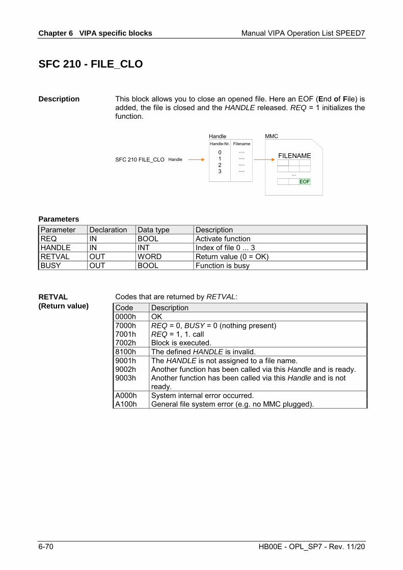
Chapter 6 VIPA specific blocks Manual VIPA Operation List SPEED7
6-70 HB00E - OPL_SP7 - Rev. 11/20
SFC 210 - FILE_CLO
This block allows you to close an opened file. Here an EOF (End of File) is added, the file is closed and the HANDLE released. REQ = 1 initializes the function.
MMC
SFC 210 FILE_CLO FILENAMEHandle
Handle-Nr. Filename
0123
....
....
....
....
Handle
...EOF
Parameter Declaration Data type Description REQ IN BOOL Activate function HANDLE IN INT Index of file 0 ... 3 RETVAL OUT WORD Return value (0 = OK) BUSY OUT BOOL Function is busy
Codes that are returned by RETVAL: Code Description 0000h OK 7000h REQ = 0, BUSY = 0 (nothing present) 7001h REQ = 1, 1. call 7002h Block is executed. 8100h The defined HANDLE is invalid. 9001h The HANDLE is not assigned to a file name. 9002h Another function has been called via this Handle and is ready. 9003h Another function has been called via this Handle and is not
ready. A000h System internal error occurred. A100h General file system error (e.g. no MMC plugged).
Description
Parameters
RETVAL (Return value)
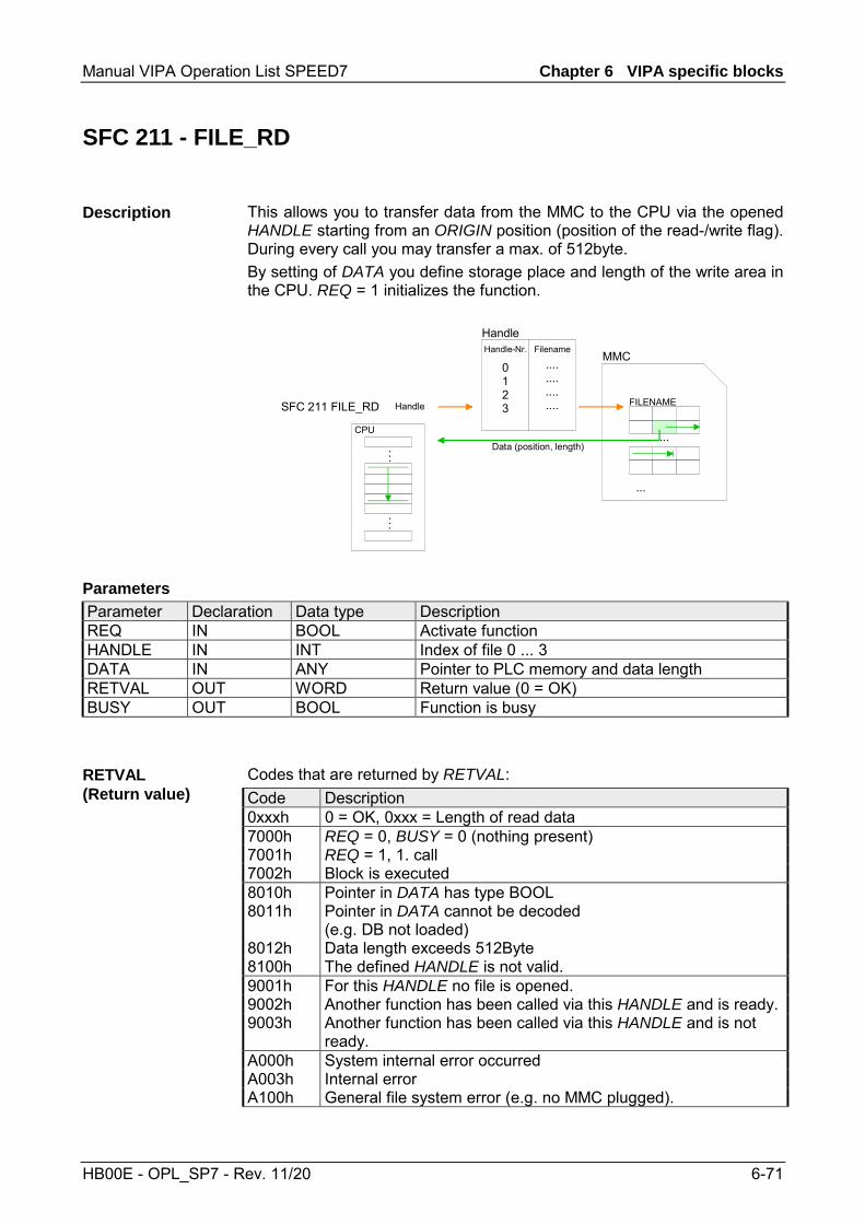
Manual VIPA Operation List SPEED7 Chapter 6 VIPA specific blocks
HB00E - OPL_SP7 - Rev. 11/20 6-71
SFC 211 - FILE_RD
This allows you to transfer data from the MMC to the CPU via the opened HANDLE starting from an ORIGIN position (position of the read-/write flag). During every call you may transfer a max. of 512byte. By setting of DATA you define storage place and length of the write area in the CPU. REQ = 1 initializes the function.
MMC
SFC 211 FILE_RD FILENAMEHandle
Handle-Nr. Filename
0123
....
....
....
....
Handle
...Data (position, length)
CPU
...
...
...
Parameter Declaration Data type Description REQ IN BOOL Activate function HANDLE IN INT Index of file 0 ... 3 DATA IN ANY Pointer to PLC memory and data length RETVAL OUT WORD Return value (0 = OK) BUSY OUT BOOL Function is busy
Codes that are returned by RETVAL: Code Description 0xxxh 0 = OK, 0xxx = Length of read data 7000h REQ = 0, BUSY = 0 (nothing present) 7001h REQ = 1, 1. call 7002h Block is executed 8010h Pointer in DATA has type BOOL 8011h Pointer in DATA cannot be decoded
(e.g. DB not loaded) 8012h Data length exceeds 512Byte 8100h The defined HANDLE is not valid. 9001h For this HANDLE no file is opened. 9002h Another function has been called via this HANDLE and is ready.9003h Another function has been called via this HANDLE and is not
ready. A000h System internal error occurred A003h Internal error A100h General file system error (e.g. no MMC plugged).
Description
Parameters
RETVAL (Return value)

Chapter 6 VIPA specific blocks Manual VIPA Operation List SPEED7
6-72 HB00E - OPL_SP7 - Rev. 11/20
SFC 212 - FILE_WR
Use this block for write access to the MMC. This writes data from the position and length of the CPU defined under Data to the MMC via the according HANDLE starting at the write/read position. During every call you may transfer a max. of 512byte. REQ = 1 initializes the function.
MMC
SFC 212 FILE_WR FILENAMEHandle
Handle-Nr. Filename
0123
....
....
....
....
Handle
...Data (position, length)
CPU
...
...
...
Parameter Declaration Data type Description REQ IN BOOL Activate function HANDLE IN INT Index of file 0 ... 3 DATA IN ANY Pointer to PLC memory and data length RETVAL OUT WORD Return value BUSY OUT BOOL Function is busy
The parameter RETVAL returns the length of the written data. The block doesn't announce an error message that the MMC is full. The user has to check himself if the number of the bytes to write corresponds to the number of written bytes returned by RETVAL.
Description
Parameters
Manual VIPA Operation List SPEED7 Chapter 6 VIPA specific blocks
HB00E - OPL_SP7 - Rev. 11/20 6-73
Codes that are returned by RETVAL: Code Description 0xxxh 0 = OK, 0xxx = Length of written data 7000h REQ = 0, BUSY = 0 (nothing present) 7001h REQ = 1, 1. call 7002h Block is executed 8010h Pointer in DATA has type BOOL. 8011h Pointer in DATA cannot be decoded
(e.g. DB not loaded). 8012h Data length exceeds 512byte. 8100h The defined HANDLE is not valid. 9001h For this Handle no file is opened. 9002h Another function has been called via this HANDLE and is ready.9003h Another function has been called via this HANDLE and is not
ready. A000h System internal error occurred. A002h File is write-protected. A003h Internal error. A100h General file system error (e.g. no MMC plugged).
RETVAL (Return value)

Chapter 6 VIPA specific blocks Manual VIPA Operation List SPEED7
6-74 HB00E - OPL_SP7 - Rev. 11/20
SFC 213 - FILE_SEK
FILE_SEK allows you to detect res. alter the position of the write/read flag of the according HANDLE. By setting ORIGIN as start position and an OFFSET you may define the write/read flag for the according HANDLE. REQ = 1 starts the function.
MMC
SFC 213 FILE_SEK FILENAMEHandleOriginOffset
Handle-Nr. Filename
0123
....
....
....
....
Handle
...
...
Parameter Declaration Data type Description REQ IN BOOL Activate function HANDLE IN INT Index of file 0 ... 3 ORIGIN IN INT 0 = file start, 1 = current position, 2 = file end RETVAL OUT WORD Return value (0 = OK) BUSY OUT BOOL Function is busy OFFSET INOUT DINT Offset write/read flag
Codes that are returned by RETVAL: Code Description 0000h OK, OFFSET contains the current write/read position 7000h REQ = 0, BUSY = 0 (nothing present) 7001h REQ = 1, 1. call 7002h Block is executed. 8100h The defined HANDLE is not valid. 9001h For this HANDLE no file is opened. 9002h Another function has been called via this HANDLE and is ready.9003h Another function has been called via this HANDLE and is not
ready. A000h System internal error occurred. A004h ORIGIN parameter is defective. A100h General file system error (e.g. no MMC plugged).
Description
Parameters
RETVAL (Return value)

Manual VIPA Operation List SPEED7 Chapter 6 VIPA specific blocks
HB00E - OPL_SP7 - Rev. 11/20 6-75
SFC 214 - FILE_REN
Using FILE_REN you may alter the file name defined in OLDNAME to the file name that you type in NEWNAME.
Attention! Please regard that you may only rename files that you've closed before with FILE_CLO. Nonobservance may cause data loss at the MMC!
MMC
SFC 214 FILE_REN FILENAMEOldNameNewName
EOF
Parameter Declaration Data type Description REQ IN BOOL Activate function MEDIA IN INT 0 = MMC OLDNAME IN STRING[254] Old name of file (must be in 8.3 format) NEWNAME IN STRING[254] New name of file (must be in 8.3 format) RETVAL OUT WORD Return value (0 = OK) BUSY OUT BOOL Function is busy.
Codes that are returned by RETVAL: Code Description 0000h OK, file has been renamed 7000h REQ = 0, BUSY = 0 (nothing present) 7001h REQ = 1, 1. call 7002h Block is executed 8010h Parameter OLDNAME is not present (e.g. DB not loaded) 8011h Error OLDNAME
(not conform with 8.3 format or special character) 8020h Parameter NEWNAME is not present (e.g. DB not loaded) 8021h Error NEWNAME
(not conform with 8.3 format or special character) A000h System internal error occurred A001h The defined MEDIA type is not valid A003h The new filename NEWNAME already exists A004h File OLDNAME is not found A006h File OLDNAME is just open A100h File system returns error at creation of the file
(e.g. no MMC plugged)
Description
Parameters
RETVAL (Return value)
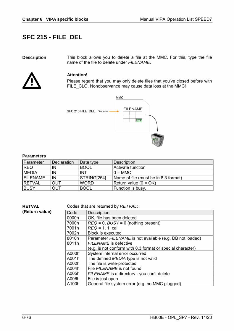
Chapter 6 VIPA specific blocks Manual VIPA Operation List SPEED7
6-76 HB00E - OPL_SP7 - Rev. 11/20
SFC 215 - FILE_DEL
This block allows you to delete a file at the MMC. For this, type the file name of the file to delete under FILENAME. Attention! Please regard that you may only delete files that you've closed before with FILE_CLO. Nonobservance may cause data loss at the MMC!
MMC
SFC 215 FILE_DEL FILENAMEFilename
EOF
Parameter Declaration Data type Description REQ IN BOOL Activate function MEDIA IN INT 0 = MMC FILENAME IN STRING[254] Name of file (must be in 8.3 format) RETVAL OUT WORD Return value (0 = OK) BUSY OUT BOOL Function is busy.
Codes that are returned by RETVAL: Code Description 0000h OK, file has been deleted 7000h REQ = 0, BUSY = 0 (nothing present) 7001h REQ = 1, 1. call 7002h Block is executed 8010h Parameter FILENAME is not available (e.g. DB not loaded) 8011h FILENAME is defective
(e.g. is not conform with 8.3 format or special character) A000h System internal error occurred A001h The defined MEDIA type is not valid A002h The file is write-protected A004h File FILENAME is not found A005h FILENAME is a directory - you can′t delete A006h File is just open A100h General file system error (e.g. no MMC plugged)
Description
Parameters
RETVAL (Return value)
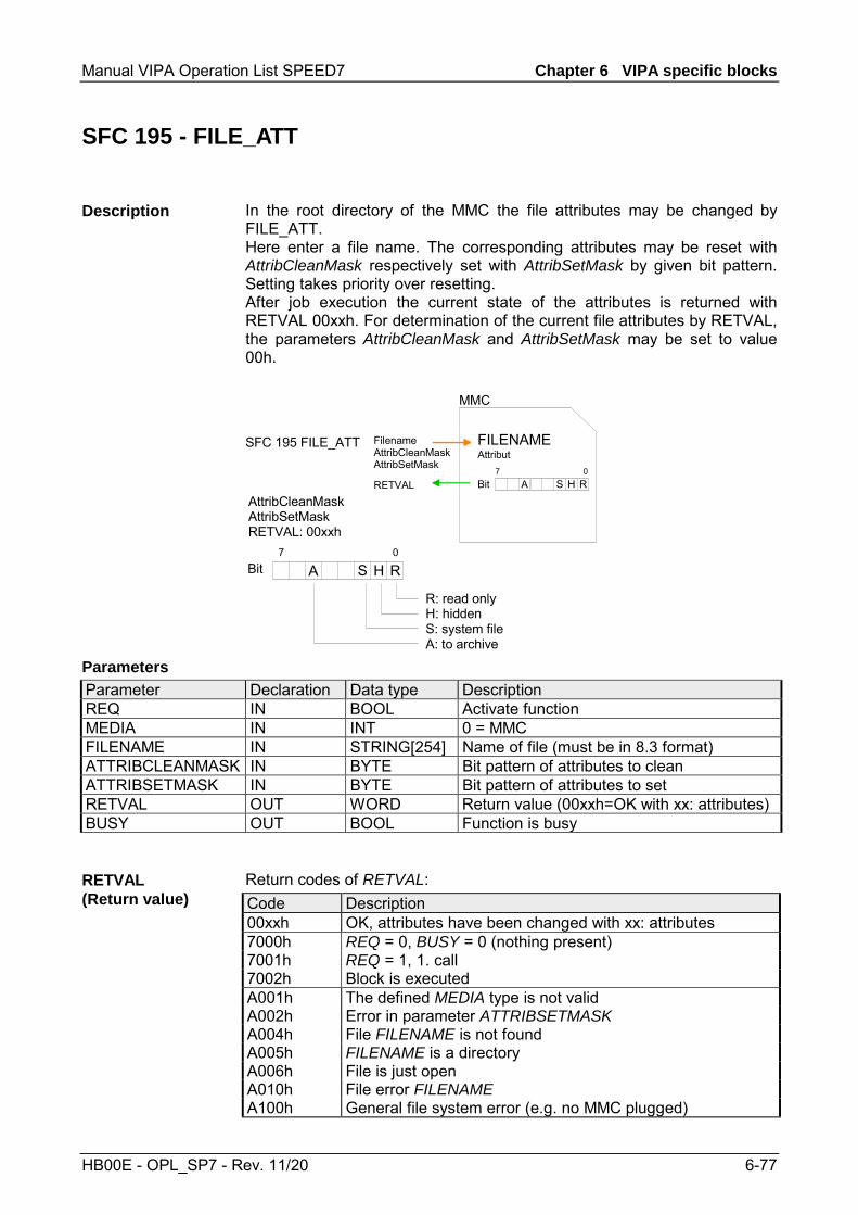
Manual VIPA Operation List SPEED7 Chapter 6 VIPA specific blocks
HB00E - OPL_SP7 - Rev. 11/20 6-77
SFC 195 - FILE_ATT
In the root directory of the MMC the file attributes may be changed by FILE_ATT. Here enter a file name. The corresponding attributes may be reset with AttribCleanMask respectively set with AttribSetMask by given bit pattern. Setting takes priority over resetting. After job execution the current state of the attributes is returned with RETVAL 00xxh. For determination of the current file attributes by RETVAL, the parameters AttribCleanMask and AttribSetMask may be set to value 00h.
MMC
SFC 195 FILE_ATT FILENAMEFilenameAttribCleanMaskAttribSetMask
RHS
Attribut
Bit7 0
A
RHSBit7 0
A
R: read onlyH: hiddenS: system fileA: to archive
AttribCleanMaskAttribSetMaskRETVAL: 00xxh
RETVAL
Parameter Declaration Data type Description REQ IN BOOL Activate function MEDIA IN INT 0 = MMC FILENAME IN STRING[254] Name of file (must be in 8.3 format) ATTRIBCLEANMASK IN BYTE Bit pattern of attributes to clean ATTRIBSETMASK IN BYTE Bit pattern of attributes to set RETVAL OUT WORD Return value (00xxh=OK with xx: attributes) BUSY OUT BOOL Function is busy
Return codes of RETVAL: Code Description 00xxh OK, attributes have been changed with xx: attributes 7000h REQ = 0, BUSY = 0 (nothing present) 7001h REQ = 1, 1. call 7002h Block is executed A001h The defined MEDIA type is not valid A002h Error in parameter ATTRIBSETMASK A004h File FILENAME is not found A005h FILENAME is a directory A006h File is just open A010h File error FILENAME A100h General file system error (e.g. no MMC plugged)
Description
Parameters
RETVAL (Return value)

Chapter 6 VIPA specific blocks Manual VIPA Operation List SPEED7
6-78 HB00E - OPL_SP7 - Rev. 11/20
PtP communication - SFC 216...218
You may de-activate the DP master integrated in the SPEED7-CPU via a hardware configuration using Object properties and the parameter "Function RS485". and thus release the RS485 interface for PtP (point-to-point) communication. The RS485 interface supports in PtP operation the serial process connection to different source res. destination systems.
The parameterization happens during runtime using the SFC 216 (SER_CFG). For this you have to store the parameters in a DB for all protocols except ASCII.
Data, which are written into the according data channel by the PLC, is stored in a FIFO send buffer (first in first out) with a size of 2x1024byte and then put out via the interface. When the interface receives data, this is stored in a FIFO receive buffer with a size of 2x1024byte and can there be read by the PLC. If the data is transferred via a protocol, the adoption of the data to the according protocol happens automatically. In opposite to ASCII and STX/ETX, the protocols 3964R, USS and Modbus require the acknow-ledgement of the partner. An additional call of the SFC 217 SER_SND causes a return value in RETVAL that includes among others recent information about the acknowledgement of the partner. Further on for USS and Modbus after a SER_SND the acknowledgement telegram must be evaluated by call of the SFC 218 SER_RCV.
Protocol FIFO Buffer
1024Byte
1024Byte
1024Byte
1024Byte
IN
OUT
RS485InterfaceProgram
SER_RCVSFC 218
CFG
RECEIVE
SENDSER_SNDSFC 217
SER_CFGSFC 216
The following SFCs are used for the serial communication: SFC Description
SFC 216 SER_CFG RS485 parameterize SFC 217 SER_SND RS485 send SFC 218 SER_RCV RS485 receive
Overview
Parameterization
Communication
RS485 PtP communication
Overview SFCs for serial communication

Manual VIPA Operation List SPEED7 Chapter 6 VIPA specific blocks
HB00E - OPL_SP7 - Rev. 11/20 6-79
SFC 216 - SER_CFG
The parameterization happens during runtime deploying the SFC 216 (SER_CFG). You have to store the parameters for STX/ETX, 3964R, USS and Modbus in a DB.
Parameter Declaration Data type Description PROTOCOL IN BYTE 1=ASCII, 2=STX/ETX, 3=3964R PARAMETER IN ANY Pointer to protocol-parameters BAUDRATE IN BYTE Number of baudrate CHARLEN IN BYTE 0=5Bit, 1=6Bit, 2=7Bit, 3=8Bit PARITY IN BYTE 0=Non, 1=Odd, 2=Even STOPBITS IN BYTE 1=1Bit, 2=1.5Bit, 3=2Bit FLOWCONTROL IN BYTE 1 (fix) RETVAL OUT WORD Return value (0 = OK)
All time settings for timeouts must be set as hexadecimal value. Find the Hex value by multiply the wanted time in seconds with the baudrate. Example: Wanted time 8ms at a baudrate of 19200Baud Calculation: 19200bit/s x 0.008s ≈ 154bit → (9Ah) Hex value is 9Ah.
Here you fix the protocol to be used. You may choose between: 1: ASCII 2: STX/ETX 3: 3964R 4: USS Master 5: Modbus RTU Master 6: Modbus ASCII Master
Description
Parameters
PROTOCOL

Chapter 6 VIPA specific blocks Manual VIPA Operation List SPEED7
6-80 HB00E - OPL_SP7 - Rev. 11/20
At ASCII protocol, this parameter is ignored. At STX/ETX, 3964R, USS and Modbus you fix here a DB that contains the communication parameters and has the following structure for the according protocols: Data block at STX/ETX DBB0: STX1 BYTE (1. Start-ID in hexadecimal) DBB1: STX2 BYTE (2. Start-ID in hexadecimal) DBB2: ETX1 BYTE (1. End-ID in hexadecimal) DBB3: ETX2 BYTE (2. End-ID in hexadecimal) DBW4: TIMEOUT WORD (max. delay time between 2 tele- grams in a time window of 10ms) Note! The start res. end sign should always be a value <20, otherwise the sign is ignored! With not used IDs please always enter FFh! Data block at 3964R DBB0: Prio BYTE (The priority of both partners must be different) DBB1: ConnAttmptNr BYTE (Number of connection trials) DBB2: SendAttmptNr BYTE (Number of telegram retries) DBW4: CharTimeout WORD (Char. delay time in 10ms time window) DBW6: ConfTimeout WORD (Acknowledgement delay time in 10ms time window) Data block at USS DBW0: Timeout WORD (Delay time in 10ms time grid) Data block at Modbus-Master DBW0: Timeout WORD (Respond delay time in 10ms time grid)
Velocity of data transfer in Bit/s (Baud). 04h: 1200Baud 05h: 1800Baud 06h: 2400Baud 07h: 4800Baud 08h: 7200Baud 09h: 9600Baud 0Ah: 14400Baud 0Bh: 19200Baud0Ch: 38400Baud 0Dh: 57600Baud 0Eh: 115200Baud
Number of data bits where a character is mapped to. 0: 5bit 1: 6bit 2: 7bit 3: 8bit
PARAMETER (as DB)
BAUD RATE
CHARLEN

Manual VIPA Operation List SPEED7 Chapter 6 VIPA specific blocks
HB00E - OPL_SP7 - Rev. 11/20 6-81
The parity is -depending on the value- even or odd. For parity control, the information bits are extended with the parity bit, that amends via its value ("0" or "1") the value of all bits to a defined status. If no parity is set, the parity bit is set to "1", but not evaluated. 0: NONE 1: ODD 2: EVEN
The stop bits are set at the end of each transferred character and mark the end of a character. 1: 1bit 2: 1.5bit 3: 2bit
The parameter FLOWCONTROL is ignored. When sending RTS=1, when receiving RTS=0.
Return values send by the block:
Error code Description 0000h no error 809Ah interface not found e. g. interface is used by PROFIBUS 8x24h Error at SFC-Parameter x, with x:
1: Error at PROTOCOL 2: Error at PARAMETER 3: Error at BAUDRATE 4: Error at CHARLENGTH 5: Error at PARITY 6: Error at STOPBITS 7: Error at FLOWCONTROL
809xh Error in SFC parameter value x, where x: 1: Error at PROTOCOL 3: Error at BAUDRATE 4: Error at CHARLENGTH 5: Error at PARITY 6: Error at STOPBITS 7: Error at FLOWCONTROL
8092h Access error in parameter DB (DB too short) 828xh Error in parameter x of DB parameter, where x:
1: Error 1. parameter 2: Error 2. parameter ...
PARITY
STOPBITS
FLOWCONTROL
RETVAL SFC 216 (Return values)

Chapter 6 VIPA specific blocks Manual VIPA Operation List SPEED7
6-82 HB00E - OPL_SP7 - Rev. 11/20
SFC 217 - SER_SND
This block sends data via the serial interface. The repeated call of the SFC 217 SER_SND delivers a return value for 3964R, USS and Modbus via RETVAL that contains, among other things, recent information about the acknowledgement of the partner station. The protocols USS and Modbus require to evaluate the receipt telegram by calling the SFC 218 SER_RCV after SER_SND.
Parameter Declaration Data type Description DATAPTR IN ANY Pointer to Data Buffer for sending data DATALEN OUT WORD Length of data sent RETVAL OUT WORD Return value (0 = OK)
Here you define a range of the type Pointer for the send buffer where the data to be sent are stored. You have to set type, start and length. Example: Data is stored in DB5 starting at 0.0 with a length of 124byte. DataPtr:=P#DB5.DBX0.0 BYTE 124
Word where the number of the sent Bytes is stored. At ASCII if data were sent by means of SFC 217 faster to the serial interface than the interface sends, the length of data to send could differ from the DATALEN due to a buffer overflow. This should be considered by the user program. With STX/ETX, 3964R, Modbus and USS always the length set in DATAPTR is stored or 0.
Description
Parameters
DATAPTR
DATALEN

Manual VIPA Operation List SPEED7 Chapter 6 VIPA specific blocks
HB00E - OPL_SP7 - Rev. 11/20 6-83
Return values of the block:
Error code Description 0000h Send data - ready 1000h Nothing sent (data length 0) 20xxh Protocol executed error free with xx bit pattern for diagnosis7001h Data is stored in internal buffer - active (busy) 7002h Transfer - active 80xxh Protocol executed with errors with xx bit pattern for
diagnosis (no acknowledgement by partner) 90xxh Protocol not executed with xx bit pattern for diagnosis
(no acknowledgement by partner) 8x24h Error in SFC parameter x, where x:
1: Error in DATAPTR 2: Error in DATALEN
8122h Error in parameter DATAPTR (e.g. DB too short) 807Fh Internal error 809Ah interface not found e.g. interface is used by PROFIBUS 809Bh interface not configured
ASCII Value Description 9000h Buffer overflow (no data send) 9002h Data too short (0byte)
STX/ETX
Value Description 9000h Buffer overflow (no data send) 9001h Data too long (>1024byte) 9002h Data too short (0byte) 9004h Character not allowed
3964R
Value Description 2000h Send ready without error 80FFh NAK received - error in communication 80FEh Data transfer without acknowledgement of partner or error
at acknowledgement 9000h Buffer overflow (no data send) 9001h Data too long (>1024byte) 9002h Data too short (0byte)
RETVAL SFC 217 (Return values)
Protocol specific RETVAL values

Chapter 6 VIPA specific blocks Manual VIPA Operation List SPEED7
6-84 HB00E - OPL_SP7 - Rev. 11/20
USS Error code Description
2000h Send ready without error 8080h Receive buffer overflow (no space for receipt) 8090h Acknowledgement delay time exceeded 80F0h Wrong checksum in respond 80FEh Wrong start sign in respond 80FFh Wrong slave address in respond 9000h Buffer overflow (no data send) 9001h Data too long (>1024byte) 9002h Data too short (<2byte)
Modbus RTU/ASCII Master
Error code Description 2000h Send ready (positive slave respond) 2001h Send ready (negative slave respond) 8080h Receive buffer overflow (no space for receipt) 8090h Acknowledgement delay time exceeded 80F0h Wrong checksum in respond 80FDh Length of respond too long 80FEh Wrong function code in respond 80FFh Wrong slave address in respond 9000h Buffer overflow (no data send) 9001h Data too long (>1024byte) 9002h Data too short (<2byte)
... Continue RETVAL SFC 217
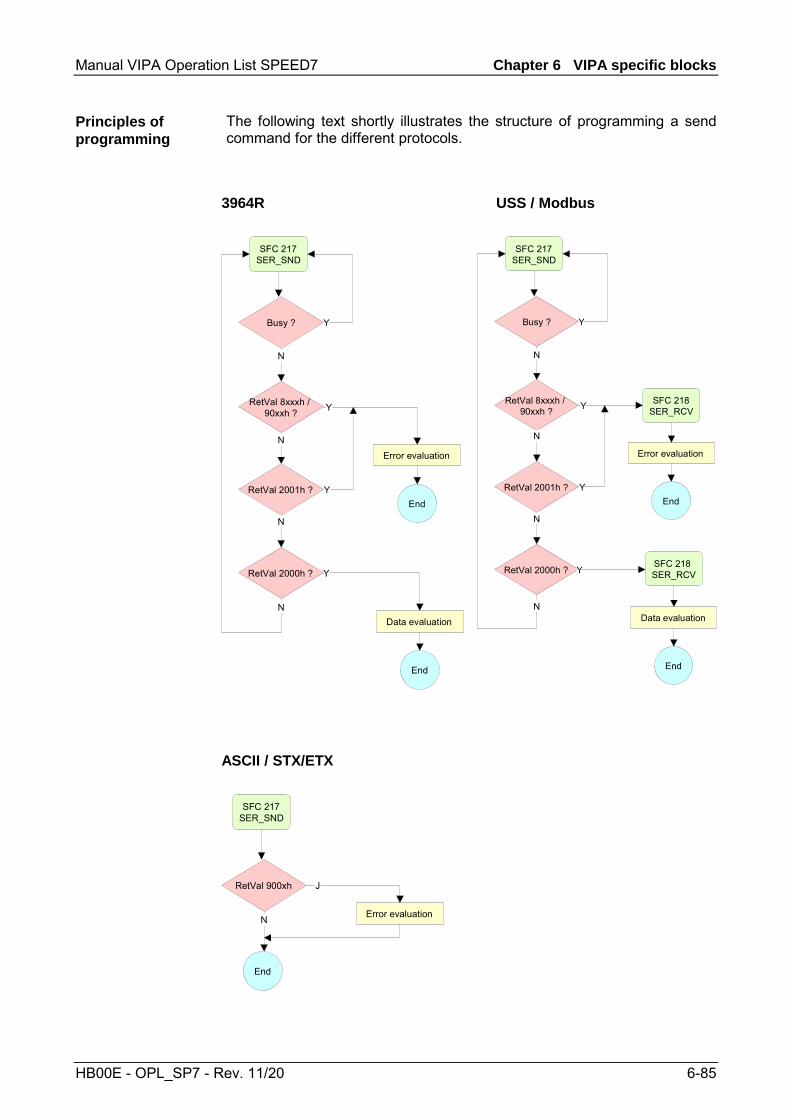
Manual VIPA Operation List SPEED7 Chapter 6 VIPA specific blocks
HB00E - OPL_SP7 - Rev. 11/20 6-85
The following text shortly illustrates the structure of programming a send command for the different protocols.
3964R USS / Modbus
SFC 217SER_SND
Busy ?
RetVal 8xxxh / 90xxh ?
RetVal 2001h ?
RetVal 2000h ?
N
N
N
Error evaluation
End
Y
Y
Y
Data evaluation
End
N
Y
SFC 217SER_SND
Busy ?
RetVal 8xxxh / 90xxh ?
RetVal 2001h ?
RetVal 2000h ?
N
N
N
SFC 218SER_RCV
Error evaluation
End
Y
Y
Y
SFC 218 SER_RCV
Data evaluation
End
N
Y
ASCII / STX/ETX
SFC 217SER_SND
RetVal 900xh
Error evaluation
End
J
N
Principles of programming

Chapter 6 VIPA specific blocks Manual VIPA Operation List SPEED7
6-86 HB00E - OPL_SP7 - Rev. 11/20
SFC 218 - SER_RCV
This block receives data via the serial interface. Using the SFC 218 SER_RCV after SER_SND with the protocols USS and Modbus the acknowledgement telegram can be read.
Parameter Declaration Data type Description DATAPTR IN ANY Pointer to Data Buffer for received data DATALEN OUT WORD Length of received data ERROR OUT WORD Error Number RETVAL OUT WORD Return value (0 = OK)
Here you set a range of the type Pointer for the receive buffer where the reception data is stored. You have to set type, start and length. Example: Data is stored in DB5 starting at 0.0 with a length of 124byte. DataPtr:=P#DB5.DBX0.0 BYTE 124 Word where the number of received Bytes is stored. At STX/ETX and 3964R, the length of the received user data or 0 is entered. At ASCII, the number of read characters is entered. This value may be different from the read telegram length. This word gets an entry in case of an error. The following error messages may be created depending on the protocol: ASCII
Bit Error Description 0 overrun Overflow, a sign couldn’t be read fast enough from
the interface 1 framing error Error that shows that a defined bit frame is not
coincident, exceeds the allowed length or contains an additional Bit sequence (Stop bit error)
2 parity Parity error 3 overflow Buffer is full
STX/ETX Bit Error Description 0 overflow The received telegram exceeds the size of the
receive buffer. 1 char A sign outside the range 20h ... 7Fh has been
received. 3 overflow Buffer is full.
Description
Parameters
DATAPTR
DATALEN
ERROR

Manual VIPA Operation List SPEED7 Chapter 6 VIPA specific blocks
HB00E - OPL_SP7 - Rev. 11/20 6-87
3964R / Modbus RTU/ASCII Master
Return values of the block:
Error code Description 0000h no error 1000h Receive buffer too small (data loss) 8x24h Error at SFC-Parameter x, with x:
1: Error at DATAPTR 2: Error at DATALEN 3: Error at ERROR
8122h Error in parameter DATAPTR (e.g. DB too short) 809Ah Serial interface not found res. interface is used by
PROFIBUS 809Bh Serial interface not configured
The following picture shows the basic structure for programming a receive command. This structure can be used for all protocols.
SFC 218SER_RCV
RetVal 0000h ?
RetVal 8xxxh ?
N Data evaluation
End
J
Error evaluation
End
N
J
Bit Error Description 0 overflow The received telegram exceeds the size of the
receive buffer.
RETVAL SFC 218 (Return value)
Principles of programming
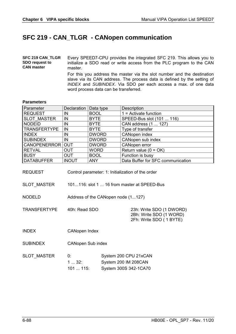
Chapter 6 VIPA specific blocks Manual VIPA Operation List SPEED7
6-88 HB00E - OPL_SP7 - Rev. 11/20
SFC 219 - CAN_TLGR - CANopen communication
Every SPEED7-CPU provides the integrated SFC 219. This allows you to initialize a SDO read or write access from the PLC program to the CAN master. For this you address the master via the slot number and the destination slave via its CAN address. The process data is defined by the setting of INDEX and SUBINDEX. Via SDO per each access a max. of one data word process data can be transferred.
Parameter Declaration Data type Description REQUEST IN BOOL 1 = Activate function SLOT_MASTER IN BYTE SPEED-Bus slot (101 ... 116) NODEID IN BYTE CAN address (1 ... 127) TRANSFERTYPE IN BYTE Type of transfer INDEX IN DWORD CANopen index SUBINDEX IN DWORD CANopen sub index CANOPENERROR OUT DWORD CANopen error RETVAL OUT WORD Return value (0 = OK) BUSY OUT BOOL Function is busy DATABUFFER INOUT ANY Data Buffer for SFC communication
Control parameter: 1: Initialization of the order 101...116: slot 1 ... 16 from master at SPEED-Bus Address of the CANopen node (1...127) 40h: Read SDO 23h: Write SDO (1 DWORD) 2Bh: Write SDO (1 WORD) 2Fh: Write SDO ( 1 BYTE) CANopen Index CANopen Sub index 0: System 200 CPU 21xCAN 1 ... 32: System 200 IM 208CAN 101 ... 115: System 300S 342-1CA70
SFC 219 CAN_TLGR SDO request to CAN master
Parameters
REQUEST
SLOT_MASTER
NODELD
TRANSFERTYPE
INDEX
SUBINDEX
SLOT_MASTER

Manual VIPA Operation List SPEED7 Chapter 6 VIPA specific blocks
HB00E - OPL_SP7 - Rev. 11/20 6-89
When no error occurs, CANOPENERROR returns 0. In case of an error CANOPENERROR contains one of the following error messages that are created by the CAN master:
Code Description 05030000h Toggle Bit not alternated 05040000h SDO Time out value reached 05040001h Client/server command specify not valid, unknown 05040002h Invalid block size (only block mode) 05040003h Invalid sequence number (only block mode) 05040004h CRC error (only block mode) 05040005h Insufficient memory 06010000h Attempt to read a write only object 06010001h Attempt to write a write only object 06020000h Object does not exist in the object dictionary 06040041h Object cannot be mapped to the PDO 06040042h The number and length of the objects to be mapped would exceed PDO
length. 06040043h General parameter incompatibility reason 06040047h General internal incompatibility reason in the device 06060000h Access failed because of an hardware error 06070010h Data type does not match, length of service parameter does not match. 06070012h Data type does not match, length of service parameter exceeded. 06070013h Data type does not match, length of service parameter shortfall. 06090011h Sub index does not exist 06090030h value range of parameter exceeded (only for write access) 06090031h Value of parameter written too high 06090032h Value of parameter written too low 06090036h Maximum value is less than minimum value 08000000h General error 08000020h Data cannot be transferred or stored to the application. 08000021h Data cannot be transferred or stored to the application because of local
control. 08000022h Data cannot be transferred or stored to the application because of the
present device state. 08000023h Object dictionary dynamic generation fails or no object dictionary is present
(e.g. object dictionary is generated from file and generation fails because of an file error.)
CANOPENERROR

Chapter 6 VIPA specific blocks Manual VIPA Operation List SPEED7
6-90 HB00E - OPL_SP7 - Rev. 11/20
When the function has been executed without error, the return value contains the valid length of the response data: 1: BYTE, 2: WORD, 4: DWORD. If an error occurs during execution, the return value contains one of the following error codes.
Code Description F021h Invalid slave address (call parameter equal 0 or higher 127) F022h Invalid transfer type (value not equal to 40h, 23h, 2Bh, 2Fh) F023h Invalid data length (data buffer too small, at SDO read access this should
be at least 4 Byte, at SDO write access at least 1Byte, 2Byte or 4 Byte). F024h SFC is not supported. F025h Write buffer in CANopen master overflow, service cannot be processed at
this time. F026h Read buffer in CANopen master overflow, service cannot be processed at
this time. F027h SDO read or write access with defective response, see CANopen Error
Codes. F028h SDO timeout
(no CANopen station with this node-ID found).
As long as BUSY = 1, the current order is not finished.
Data area via that the SFC communicates. Set here an ANY pointer of the type Byte. SDO read access: Destination area for the read user data. SDO write access: Source area for the user data to write.
Note! When the SDO request has been executed without errors, RETVAL contains the length of the valid response data (1, 2 or 4 byte) and CANOPENERROR the value 0.
RETVAL
BUSY
DATABUFFER

Manual VIPA Operation List SPEED7 Chapter 6 VIPA specific blocks
HB00E - OPL_SP7 - Rev. 11/20 6-91
SFC 254 - RW_SBUS - IBS communication
This block serves the INTERBUS-FCs 20x as communication block between INTERBUS master and CPU. For the usage of the INTERBUS-FCs 20x the SFC 254 must be included in your project as block.
Name Declaration Type Description READ/WRITE IN Byte 0 = Read, 1 = Write LADDR IN WORD Logical Address of INTERBUS master IBS_ADDR IN WORD Address at INTERBUS Master DATAPOINTER IN ANY Pointer to PLC data RETVAL OUT WORD Return value (0 = OK)
This defines the transfer direction seen from the CPU. Read reads the data from the Dual port memory of the INTERBUS master.
Enter the address (Logical Address) from where on the register of the master is mapped in the CPU. At the start-up of the CPU, the INTERBUS master are stored in the I/O address range of the CPU following the shown formula if no hardware configuration is present:
Start address = 256⋅ (slot-101)+2048 The slot numbers at the SPEED-Bus start with 101 at the left side of the CPU and raises from the right to the left. For example the 1. slot has the address 2048, the 2. the address 2304 etc.
Address in the address range of the INTERBUS master.
Pointer to the data area of the CPU.
Value that the function returns. 0 means OK.
Description
Parameters
READ/WRITE
LADDR
IBS_ADDR
DATAPOINTER
RETVAL

Chapter 6 VIPA specific blocks Manual VIPA Operation List SPEED7
6-92 HB00E - OPL_SP7 - Rev. 11/20

Manual VIPA Operation List SPEED7 Chapter 7 System Status List SSL
HB00E - OPL_SP7 - Rev. 11/20 7-1
Chapter 7 System Status List SSL
This chapter describes all the partial lists of the system status list, readable via SFC 51 RDSYSST or via Hardware configurator.
Topic Page Chapter 7 System Status List SSL .................................................. 7-1
Overview SSL....................................................................................... 7-2 Overview - SSL partial lists................................................................... 7-3 Module Identification - SSL-ID: xy11h .................................................. 7-4 CPU Characteristics - SSL-ID: xy12h ................................................... 7-5 Memory Areas - SSL-ID: xy13h............................................................ 7-7 System areas - SSL-ID: xy14h ............................................................. 7-8 Component Identification - SSL-ID: xy1Ch ........................................... 7-9 Interrupt Status - SSL-ID: xy22h......................................................... 7-10 Communication Status Data - SSL-ID: xy32h..................................... 7-12 Status of the Module LEDs - SSL-ID: xy74h....................................... 7-14 Status Information CPU - SSL-ID: xy91h............................................ 7-15 Station Status Information - SSL-ID: xy92h ........................................ 7-18 Diagnostic Buffer - SSL-ID: xyA0h ..................................................... 7-20 Diagnostic Information - SSL-ID: 00B1h............................................. 7-21 Diagnostic Record set 1 - SSL-ID: 00B2h .......................................... 7-22 Diagnostic Data - SSL-ID: 00B3h ....................................................... 7-23 Diagnostic Data of a DP slave - SSL-ID: 00B4h ................................. 7-24
Overview
Content

Chapter 7 System Status List SSL Manual VIPA Operation List SPEED7
7-2 HB00E - OPL_SP7 - Rev. 11/20
Overview SSL
The SSL (system status list) describes the current status of a automation system. It contains the following information: • System data
These are fixed or assigned characteristics data of a CPU as configuration of the CPU, status of the priority classes and communication.
• Module status data in the CPU This describes the current status of the components monitored by system diagnostic functions.
• Diagnostics data The diagnostics data of modules with diagnostic capabilities assigned to the CPU.
• Diagnostics buffer Diagnostic entries of the diagnostic buffer in the order in which they occur.
Only partial lists of the SSL may be accessed. The partial lists are virtual list, this means, they are only created by the operating system of the CPUs when specifically requested and my only be read. A partial list or a list extract may be read e.g. by means of the SFC 51 RDSYSST. Here with the parameters SSL_ID and INDEX you define the kind of information to read. A partial list always has the following structure: • Header - SSL-ID - Index - Length of the record set in byte - Number of record sets of the partial list • Record sets
A record set of a partial list has a certain length, depending on the information of the partial list. It depends on the partial list as the data words are used in a record set.
The SSL-ID has the following structure:
SSL-ID High byte Low byte
Bit number 15 14 13 12 11 10 9 8 7 6 5 4 3 2 1 0 Module class:
CPU: 0000 IM: 0100 FM: 1000 CP: 1100
Number of the partial list extract: Definition of the subset of the partial list
Number of the partial list: Definition of the partial list of the SSL
SSL
SSL partial list
SSL-ID

Manual VIPA Operation List SPEED7 Chapter 7 System Status List SSL
HB00E - OPL_SP7 - Rev. 11/20 7-3
Overview - SSL partial lists
In the following all the possible SSL partial lists with additional SSL-ID are listed, which are supported by the SPEED7 system. SSL partial lists, which are only for internal usage, are no more described. SSL partial list SSL-ID Module identification xy11h CPU characteristics xy12h User memory areas xy13h System areas xy14h Identification components xy1Ch Interrupt status xy22h Communication: status data xy32h Status of the LEDs xy74h Status information CPU xy91h Stations status information xy92h Diagnostic buffer of the CPU xyA0h Module diagnostic information (record set 0) xyB1h Module diagnostic information (record set 1) via physical address
xyB2h
Module diagnostic information (record set 1) via logical address
xyB3h
Diagnostic data of a DP slave xyB4h
SSL partial lists
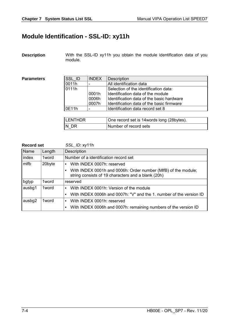
Chapter 7 System Status List SSL Manual VIPA Operation List SPEED7
7-4 HB00E - OPL_SP7 - Rev. 11/20
Module Identification - SSL-ID: xy11h
With the SSL-ID xy11h you obtain the module identification data of you module.
SSL_ID INDEX Description 0011h - All identification data 0111h
0001h 0006h 0007h
Selection of the identification data: Identification data of the module Identification data of the basic hardware Identification data of the basic firmware
0E11h - Identification data record set 8 LENTHDR One record set is 14words long (28bytes). N_DR Number of record sets
SSL_ID: xy11h Name Length Description index 1word Number of a identification record set mlfb 20byte • With INDEX 0007h: reserved
• With INDEX 0001h and 0006h: Order number (MlfB) of the module; string consists of 19 characters and a blank (20h)
bgtyp 1word reserved ausbg1 1word • With INDEX 0001h: Version of the module
• With INDEX 0006h and 0007h: "V" and the 1. number of the version ID ausbg2 1word • With INDEX 0001h: reserved
• With INDEX 0006h and 0007h: remaining numbers of the version ID
Description
Parameters
Record set

Manual VIPA Operation List SPEED7 Chapter 7 System Status List SSL
HB00E - OPL_SP7 - Rev. 11/20 7-5
CPU Characteristics - SSL-ID: xy12h
Here you can determine the hardware-specific characteristics of your CPU by specifying the appropriate feature code.
SSL_ID INDEX Description 0012h - All CPU characteristics 0112h
0000h 0100h 0200h 0300h
CPU characteristics of one group: MC7 processing unit Time system System response MC7 language description of the CPU
0E11h 0F12h SSL partial list header information LENTHDR One record set is 1word long (2bytes). N_DR Number of record sets SSL_ID: 0012h All record sets of the CPU characteristics relevant for your CPU are listed. They follow completely one behind the other. One record set is 1word long. For each feature there is an ID. This ID is 1word long. You will find the list of the characteristics IDs on the following page. SSL_ID: 0112h All data records relevant for the group are listed. They follow completely one behind the other.
Description
Parameters
Record set
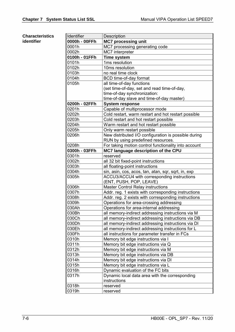
Chapter 7 System Status List SSL Manual VIPA Operation List SPEED7
7-6 HB00E - OPL_SP7 - Rev. 11/20
Identifier Description 0000h - 00FFh MC7 processing unit 0001h MC7 processing generating code 0002h MC7 interpreter 0100h - 01FFh Time system 0101h 1ms resolution 0102h 10ms resolution 0103h no real time clock 0104h BCD time-of-day format 0105h all time-of-day functions
(set time-of-day, set and read time-of-day, time-of-day synchronization: time-of-day slave and time-of-day master)
0200h - 02FFh System response 0201h Capable of multiprocessor mode 0202h Cold restart, warm restart and hot restart possible 0203h Cold restart and hot restart possible 0204h Warm restart and hot restart possible 0205h Only warm restart possible 0206h New distributed I/O configuration is possible during
RUN by using predefined resources. 0208h For taking motion control functionality into account 0300h - 03FFh MC7 language description of the CPU 0301h reserved 0302h all 32 bit fixed-point instructions 0303h all floating-point instructions 0304h sin, asin, cos, acos, tan, atan, sqr, sqrt, in, exp 0305h ACCU3/ACCU4 with corresponding instructions
(ENT, PUSH, POP, LEAVE) 0306h Master Control Relay instructions 0307h Addr. reg. 1 exists with corresponding instructions 0308h Addr. reg. 2 exists with corresponding instructions 0309h Operations for area-crossing addressing 030Ah Operations for area-internal addressing 030Bh all memory-indirect addressing instructions via M 030Ch all memory-indirect addressing instructions via DB 030Dh all memory-indirect addressing instructions via DI 030Eh all memory-indirect addressing instructions for L 030Fh all instructions for parameter transfer in FCs 0310h Memory bit edge instructions via I 0311h Memory bit edge instructions via Q 0312h Memory bit edge instructions via M 0313h Memory bit edge instructions via DB 0314h Memory bit edge instructions via DI 0315h Memory bit edge instructions via L 0316h Dynamic evaluation of the FC bits 0317h Dynamic local data area with the corresponding
instructions 0318h reserved 0319h reserved
Characteristics identifier
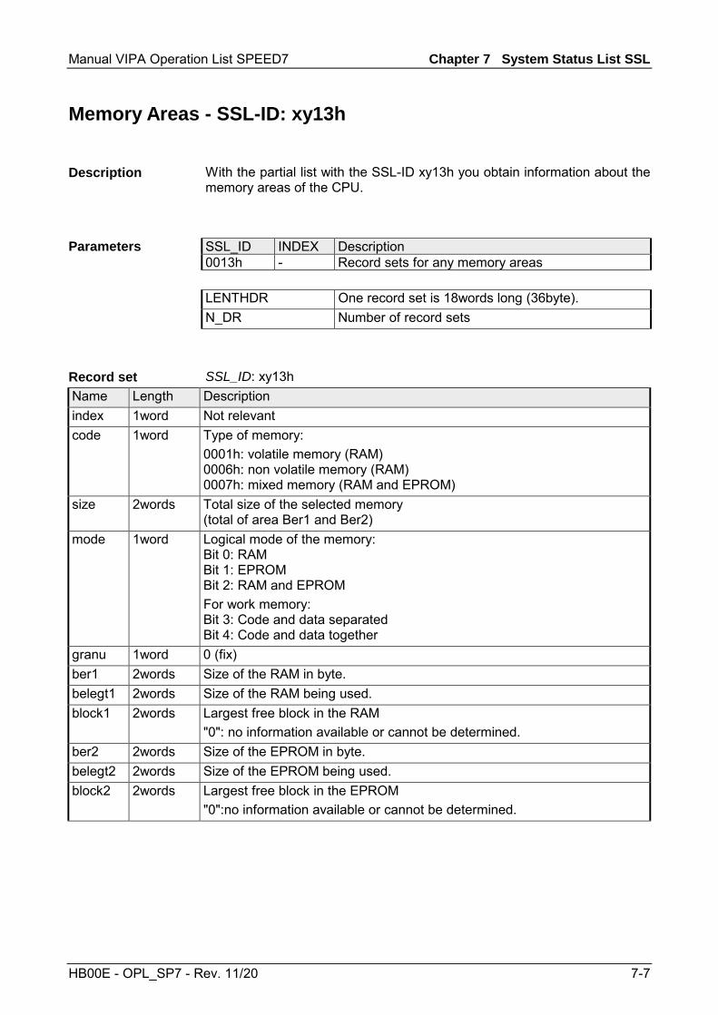
Manual VIPA Operation List SPEED7 Chapter 7 System Status List SSL
HB00E - OPL_SP7 - Rev. 11/20 7-7
Memory Areas - SSL-ID: xy13h
With the partial list with the SSL-ID xy13h you obtain information about the memory areas of the CPU.
SSL_ID INDEX Description 0013h - Record sets for any memory areas LENTHDR One record set is 18words long (36byte). N_DR Number of record sets
SSL_ID: xy13h Name Length Description index 1word Not relevant code 1word Type of memory:
0001h: volatile memory (RAM) 0006h: non volatile memory (RAM) 0007h: mixed memory (RAM and EPROM)
size 2words Total size of the selected memory (total of area Ber1 and Ber2)
mode 1word Logical mode of the memory: Bit 0: RAM Bit 1: EPROM Bit 2: RAM and EPROM For work memory: Bit 3: Code and data separated Bit 4: Code and data together
granu 1word 0 (fix) ber1 2words Size of the RAM in byte. belegt1 2words Size of the RAM being used. block1 2words Largest free block in the RAM
"0": no information available or cannot be determined. ber2 2words Size of the EPROM in byte. belegt2 2words Size of the EPROM being used. block2 2words Largest free block in the EPROM
"0":no information available or cannot be determined.
Description
Parameters
Record set

Chapter 7 System Status List SSL Manual VIPA Operation List SPEED7
7-8 HB00E - OPL_SP7 - Rev. 11/20
System areas - SSL-ID: xy14h
If you read the partial list with SSL-ID xy14h, you obtain information about the system areas of the CPU.
SSL_ID INDEX Description 0014h - All system areas of a CPU 0F14h - SSL partial list header information LENTHDR One record set is 4words long (8byte) N_DR Number of record sets
You must at least assign a number of 9 record sets. If you select a target area, which is too small, the SFC 51 RDSYSST does not provide a record set.
SSL_ID: xy14h Name Length Description index 1word Index of the system area
0001h: PII (quantity in byte) 0002h: PIQ (quantity in byte) 0004h: Timers (quantity ) 0005h: Counters (quantity ) 0006h: Quantity of bytes in the logical address area. 0007h: Local data (entire local data area of the CPU in byte) 0008h: Memory (number in bytes)
code 1word Memory type: 0001h: RAM 0002h: EPROM
quantity 1word Number of elements of the system area defined by Index. remain 1word Number of retentive elements defined by Index.
Description
Parameters
Record set

Manual VIPA Operation List SPEED7 Chapter 7 System Status List SSL
HB00E - OPL_SP7 - Rev. 11/20 7-9
Component Identification - SSL-ID: xy1Ch
If you read the partial list you can identify the CPU or the automation system. SSL_ID INDEX Description 001Ch - Identification of all components 011Ch
0001h 0002h 0003h 0005h 0006h 0007h 0008h
Identification of one components: Name of the automation system Name of the module Plant identification of the module Serial number of the module OD of the CPU (always "0") Module type name Serial number of the MCC
011Ch 00FFh CID of the MCC (only at SZL_ID x11Ch) 021Ch reserved 031Ch reserved 0F1Ch - SSL partial list header information LENTHDR A record set is 17words long (34byte). N_DR Number of record sets A record set of the partial list with SSL_ID: 011Ch has the following structure:
INDEX Name Length Description index 1word Index of the component: 0001h name 12words Name of the automation system (max. 24 characters) *
0001h
res 4words reserved index 1word Index of the component: 0002h name 12words Name of the module (max. 24 characters) *
0002h
res 4words reserved index 1word Index of the component: 0003h tag 16words Plant identification of the module(max. 32 characters) *
0003h
res 4words reserved index 1word Index of the component: 0005h serialn 12words Serial number of the module (max. 24 characters) *
0005h
res 3words reserved index 1word Index of the component: 0007h 0007h cputypname 16words Module type name as character string (max. 32 characters) * index 1word Index of the component: 0008h 0008h sn_mcc 16words Serial number of the MCC (max. 32 characters) *. The string
ends immediately after "MMC" if no MCC is installed. index 1word Index of the component: 00FFh 00FFh cid 16words CID of the MCC
*) If names and designations are shorter than the corresponding max. characters, the gaps are filled with 00h.
Description
Parameters
Record set
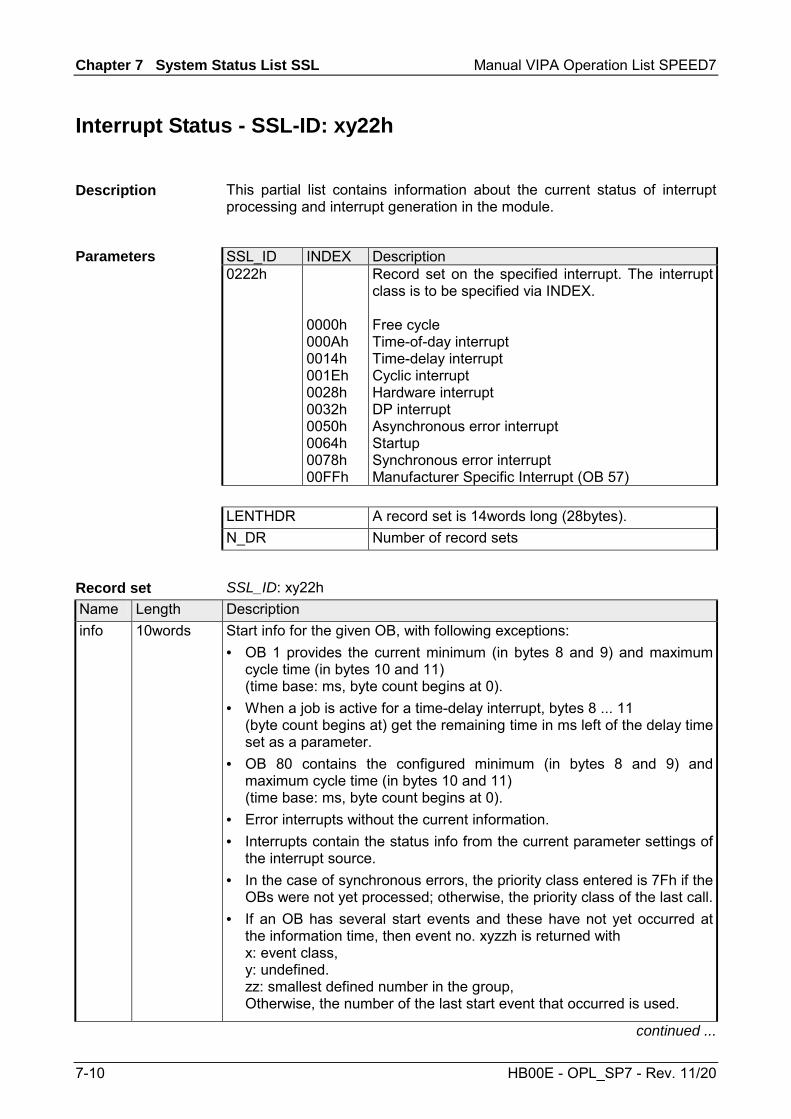
Chapter 7 System Status List SSL Manual VIPA Operation List SPEED7
7-10 HB00E - OPL_SP7 - Rev. 11/20
Interrupt Status - SSL-ID: xy22h
This partial list contains information about the current status of interrupt processing and interrupt generation in the module.
SSL_ID INDEX Description 0222h Record set on the specified interrupt. The interrupt
class is to be specified via INDEX.
0000h 000Ah 0014h 001Eh 0028h 0032h 0050h 0064h 0078h 00FFh
Free cycle Time-of-day interrupt Time-delay interrupt Cyclic interrupt Hardware interrupt DP interrupt Asynchronous error interrupt Startup Synchronous error interrupt Manufacturer Specific Interrupt (OB 57)
LENTHDR A record set is 14words long (28bytes). N_DR Number of record sets
SSL_ID: xy22h Name Length Description info 10words Start info for the given OB, with following exceptions:
• OB 1 provides the current minimum (in bytes 8 and 9) and maximum cycle time (in bytes 10 and 11) (time base: ms, byte count begins at 0).
• When a job is active for a time-delay interrupt, bytes 8 ... 11 (byte count begins at) get the remaining time in ms left of the delay time set as a parameter.
• OB 80 contains the configured minimum (in bytes 8 and 9) and maximum cycle time (in bytes 10 and 11) (time base: ms, byte count begins at 0).
• Error interrupts without the current information. • Interrupts contain the status info from the current parameter settings of
the interrupt source. • In the case of synchronous errors, the priority class entered is 7Fh if the
OBs were not yet processed; otherwise, the priority class of the last call.• If an OB has several start events and these have not yet occurred at
the information time, then event no. xyzzh is returned with x: event class, y: undefined. zz: smallest defined number in the group, Otherwise, the number of the last start event that occurred is used.
continued ...
Description
Parameters
Record set

Manual VIPA Operation List SPEED7 Chapter 7 System Status List SSL
HB00E - OPL_SP7 - Rev. 11/20 7-11
... continue Name Length Description al 1 1word Processing identifiers:
Bit 0: Interrupt event is caused by parameters: 0: enabled 1: disabled Bit 1: Interrupt event as per SFC 39 DIS_IRT 0: not locked 1: locked Bit 2: 1: Interrupt source is active (generation job ready for time interrupts, time-of-day/time-delay
interrupt OB started, cyclic interrupt OB was configured). Bit 4: Interrupt OB 0: is not loaded 1: is loaded Bit 5: Interrupt OB is by TIS: 0: enabled 1: disabled Bit 6: Entry in diagnostic buffer 0: enabled 1: disabled
al 2 1word Reaction with not loaded/locked OB Bit 0: 1: Lock interrupt source Bit 1: 1: Generate interrupt event error Bit 2: 1: CPU goes into STOP mode Bit 3: 1: Interrupt only discarded
al 3 2words reserved

Chapter 7 System Status List SSL Manual VIPA Operation List SPEED7
7-12 HB00E - OPL_SP7 - Rev. 11/20
Communication Status Data - SSL-ID: xy32h
If you read this partial list you obtain the status data of module communication.
SSL_ID INDEX Description 0132h Status data of one CPU communication section
0008h
Time system
LENTHDR A record set is 20words long (40bytes). N_DR Number of record sets
SSL_ID: 0132h INDEX 0008h The partial list extract contains information about the status of the 16bit run-time meter 0 ... 7.
Name Length Description index 1word 0008h: Time system status zykl 1word reserved korr 1word Correction factor for the time clock 0 1word Run-time meter 0: time in hours clock 1 1word Run-time meter 1: time in hours clock 2 1word Run-time meter 2: time in hours clock 3 1word Run-time meter 3: time in hours clock 4 1word Run-time meter 4: time in hours clock 5 1word Run-time meter 5: time in hours clock 6 1word Run-time meter 6: time in hours clock 7 1word Run-time meter 7: time in hours time 4words Current date and time (format: date_and_time) bszl_0 1byte Bit x: Run-time meter x with 0 ≤ x ≤ 7
1: Run-time meter active bszl_1 1byte reserved bszü_0 1byte Bit x: Run-time meter overflow x with 0 ≤ x ≤ 7
1: overflow bszü_1 1byte reserved status 1word Time status (for bit assignment, see below) res 3byte reserved status_valid 1byte Validity of variable status:
01h: status valid
Description
Parameters
Record set
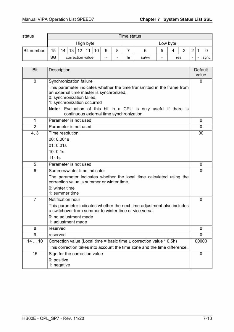
Manual VIPA Operation List SPEED7 Chapter 7 System Status List SSL
HB00E - OPL_SP7 - Rev. 11/20 7-13
status Time status High byte Low byte
Bit number 15 14 13 12 11 10 9 8 7 6 5 4 3 2 1 0 SG correction value - - hr su/wi - res - - sync
Bit Description Default
value 0 Synchronization failure
This parameter indicates whether the time transmitted in the frame from an external time master is synchronized. 0: synchronization failed, 1: synchronization occurred Note: Evaluation of this bit in a CPU is only useful if there is
continuous external time synchronization.
0
1 Parameter is not used. 0 2 Parameter is not used. 0
4, 3 Time resolution 00: 0.001s 01: 0.01s 10: 0.1s 11: 1s
00
5 Parameter is not used. 0 6 Summer/winter time indicator
The parameter indicates whether the local time calculated using the correction value is summer or winter time. 0: winter time 1: summer time
0
7 Notification hour This parameter indicates whether the next time adjustment also includes a switchover from summer to winter time or vice versa. 0: no adjustment made 1: adjustment made
0
8 reserved 0 9 reserved 0
14 ... 10 Correction value (Local time = basic time ± correction value * 0.5h) This correction takes into account the time zone and the time difference.
00000
15 Sign for the correction value 0: positive 1: negative
0
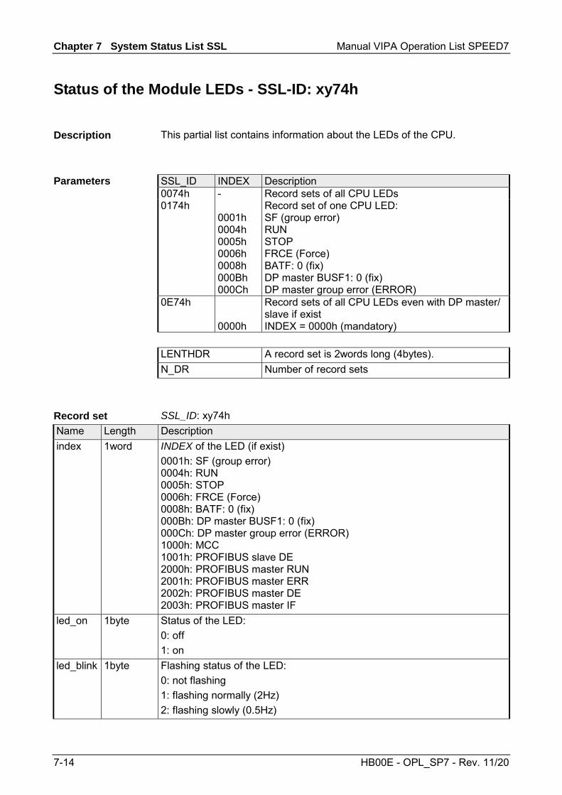
Chapter 7 System Status List SSL Manual VIPA Operation List SPEED7
7-14 HB00E - OPL_SP7 - Rev. 11/20
Status of the Module LEDs - SSL-ID: xy74h
This partial list contains information about the LEDs of the CPU.
SSL_ID INDEX Description 0074h - Record sets of all CPU LEDs 0174h
0001h 0004h 0005h 0006h 0008h 000Bh 000Ch
Record set of one CPU LED: SF (group error) RUN STOP FRCE (Force) BATF: 0 (fix) DP master BUSF1: 0 (fix) DP master group error (ERROR)
0E74h 0000h
Record sets of all CPU LEDs even with DP master/ slave if exist INDEX = 0000h (mandatory)
LENTHDR A record set is 2words long (4bytes). N_DR Number of record sets
SSL_ID: xy74h Name Length Description index 1word INDEX of the LED (if exist)
0001h: SF (group error) 0004h: RUN 0005h: STOP 0006h: FRCE (Force) 0008h: BATF: 0 (fix) 000Bh: DP master BUSF1: 0 (fix) 000Ch: DP master group error (ERROR) 1000h: MCC 1001h: PROFIBUS slave DE 2000h: PROFIBUS master RUN 2001h: PROFIBUS master ERR 2002h: PROFIBUS master DE 2003h: PROFIBUS master IF
led_on 1byte Status of the LED: 0: off 1: on
led_blink 1byte Flashing status of the LED: 0: not flashing 1: flashing normally (2Hz) 2: flashing slowly (0.5Hz)
Description
Parameters
Record set

Manual VIPA Operation List SPEED7 Chapter 7 System Status List SSL
HB00E - OPL_SP7 - Rev. 11/20 7-15
Status Information CPU - SSL-ID: xy91h
If you read the partial list, you obtain the status information of modules assigned to the CPU.
SSL_ID INDEX Description 0091h - Module status information of all plugged-in modules 0191h - Status information of all not-deactivated modules 0291h - Module status information of all faulty and not-
deactivated modules 0391h - Module status information of all unavailable modules0591h - Module status information of all modules
(host module -central modules) 0991h xx00h Module status information of all DP master systems xx: contains the DP master system ID. 0A91h - Status information of all DP master systems. 4C91h
adr Module status information of a module connected to an external DP interface module via the logical base address. Bit 14 ... 0: logical base address of the module Bit 15: 0: input, 1: output
0D91h
xx00h All modules in the rack With xx you have to specify the number of the rack.
xxyyh All modules of a DP station or all I/O devices With xx you have to specify the DP master system ID and with yy the stations number.
0E91h - Module status information of all configured modules(central, distributed PROFIBUS DP).
0F91h - Only SSL partial list header information LENTHDR A record set is 8words long (16bytes). N_DR Number of record sets. Depending on the product
the number of records transferred can be lower.
Description
Parameters
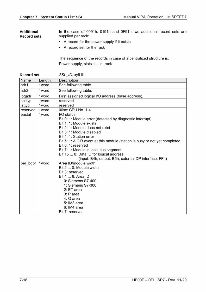
Chapter 7 System Status List SSL Manual VIPA Operation List SPEED7
7-16 HB00E - OPL_SP7 - Rev. 11/20
In the case of 0091h, 0191h and 0F91h two additional record sets are supplied per rack: • A record for the power supply if it exists • A record set for the rack The sequence of the records in case of a centralized structure is: Power supply, slots 1 ... n, rack SSL_ID: xy91h:
Name Length Description adr1 1word See following table. adr2 1word See following table. logadr 1word First assigned logical I/O address (base address). solltyp 1word reserved isttyp 1word reserved reserved 1word 00xx: CPU No. 1-4 eastat 1word I/O status:
Bit 0: 1: Module error (detected by diagnostic interrupt) Bit 1: 1: Module exists Bit 2: 1: Module does not exist Bit 3: 1: Module disabled Bit 4: 1: Station error Bit 5: 1: A CiR event at this module /station is busy or not yet completed. Bit 6: 1: reserved Bit 7: 1: Module in local bus segment Bit 15 ... 8: Data ID for logical address
(input: B4h, output: B5h, external DP interface: FFh) ber_bgbr 1word Area ID/module width
Bit 2 ... 0: Module width Bit 3: reserved Bit 4 ... 6: Area ID 0: Siemens S7-400 1: Siemens S7-300 2: ET area 3: P area 4: Q area 5: IM3 area 6: IM4 area Bit 7: reserved
Additional Record sets
Record set

Manual VIPA Operation List SPEED7 Chapter 7 System Status List SSL
HB00E - OPL_SP7 - Rev. 11/20 7-17
adr1 At a centralized configuration adr1 High byte Low byte
Bit number 15 14 13 12 11 10 9 8 7 6 5 4 3 2 1 0 0 Rack number (0 ... 31) At a decentralized configuration with PROFIBUS DP
Bit 15: 0 is the ID for PROFIBUS adr1 High byte Low byte
Bit number 15 14 13 12 11 10 9 8 7 6 5 4 3 2 1 0 0 DP master system ID (1 ... 32) Station number (0 ... 127) At a decentralized configuration with PROFINET IO
For the full PROFINET IO-System-ID 100 is to be added to Bit 12 ... 14. Bit 15: 1 is the ID for PROFINET
adr1 High byte Low byte
Bit number 15 14 13 12 11 10 9 8 7 6 5 4 3 2 1 0 1 PROFINET IO
system ID (0 ... 15)
Station number (0 ... 2047)
adr2 At a centralized respectively decentralized structure with PROFIBUS DP adr2 High byte Low byte
Bit number 15 14 13 12 11 10 9 8 7 6 5 4 3 2 1 0 Slot number Submodule slot number

Chapter 7 System Status List SSL Manual VIPA Operation List SPEED7
7-18 HB00E - OPL_SP7 - Rev. 11/20
Station Status Information - SSL-ID: xy92h
If you read this partial list, you obtain information about the expected and the current hardware configuration of centrally installed stations of a DP master system, connected via a DP interface.
SSL_ID INDEX Description 0092h 4092h
DPM-ID Expected status of the central stations of a DP master system
0192h 4192h
DPM-ID Activation status of the stations of a DP master system
0292h 4292h
DPM-ID Actual status of the stations of a DP master system
0692h 4692h
DPM-ID Diagnostic status of the expansion racks in the central configuration of the stations of a DP master system
LENTHDR One record set is 8words long (16bytes). N_DR Number of record sets
SSL_ID: xy92h: Name Length Description status_0...status_15 16byte Rack status / station status or backup status
(The backup status is only relevant for DP modules.) 0092h: 0: Rack/station not configured
1: Rack/station configured 4092h: 0: Station not configured
1: Station configured 0192h: 0: Station is not configured or configured and activated
1: Station is configured and activated 0292h: 0: Rack/station failure, deactivated or not configured
1: Rack/station exists and is activated 4292h: 0: station failure, deactivated or not configured
1: station exists, activated and has not failed 0692h: 0: All modules of the expansion rack / of a station exist,
are available with no problems and activated. 1: At least 1 module of the expansion rack / of a station
is not OK or the station is deactivated. 4692h: 0: All modules of a station exist, are available with no
problems, and activated. 1: At least 1 module of a station is not OK or the station
is deactivated. continued ...
Description
Parameters
Record set
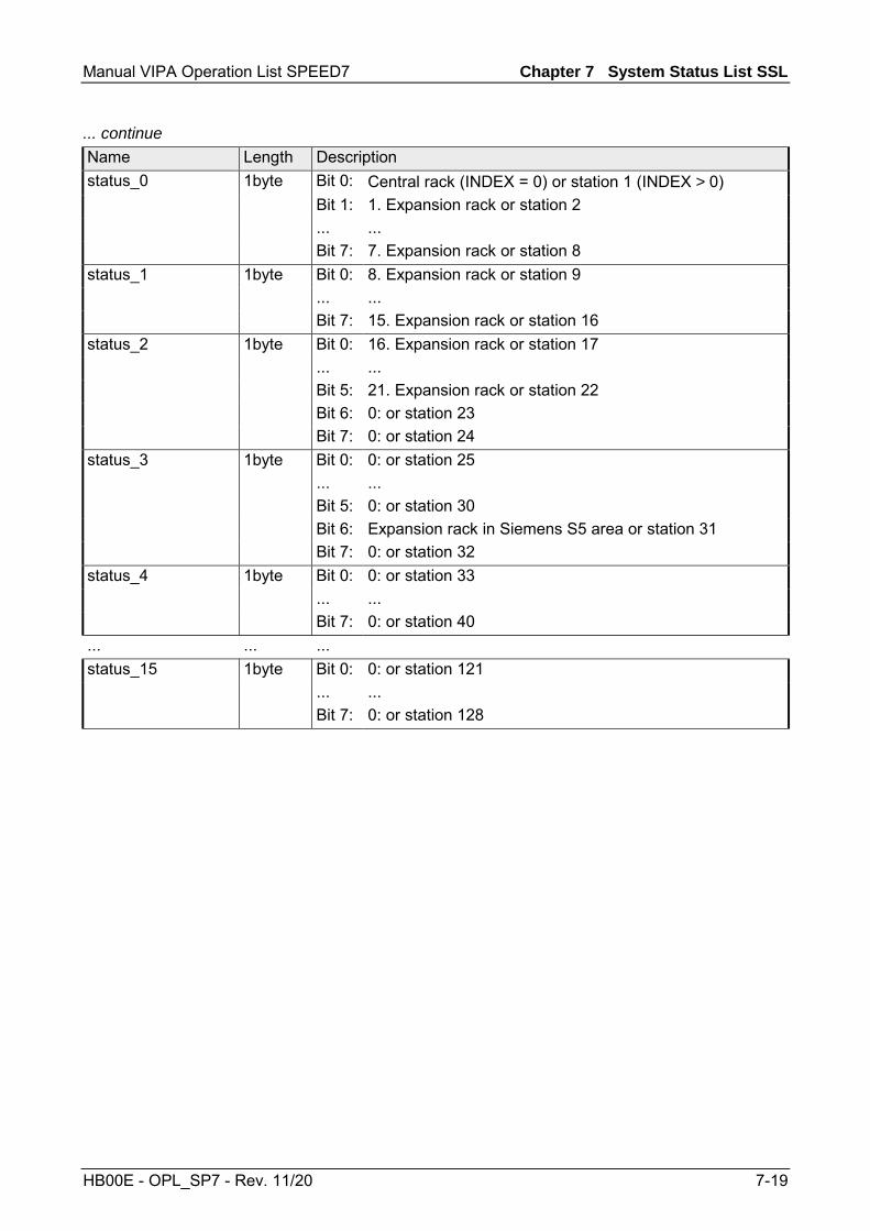
Manual VIPA Operation List SPEED7 Chapter 7 System Status List SSL
HB00E - OPL_SP7 - Rev. 11/20 7-19
... continue Name Length Description status_0 1byte Bit 0: Central rack (INDEX = 0) or station 1 (INDEX > 0) Bit 1: 1. Expansion rack or station 2 ... ... Bit 7: 7. Expansion rack or station 8 status_1 1byte Bit 0: 8. Expansion rack or station 9 ... ... Bit 7: 15. Expansion rack or station 16 status_2 1byte Bit 0: 16. Expansion rack or station 17 ... ... Bit 5: 21. Expansion rack or station 22 Bit 6: 0: or station 23 Bit 7: 0: or station 24 status_3 1byte Bit 0: 0: or station 25 ... ... Bit 5: 0: or station 30 Bit 6: Expansion rack in Siemens S5 area or station 31 Bit 7: 0: or station 32 status_4 1byte Bit 0: 0: or station 33 ... ... Bit 7: 0: or station 40 ... ... ... status_15 1byte Bit 0: 0: or station 121 ... ... Bit 7: 0: or station 128
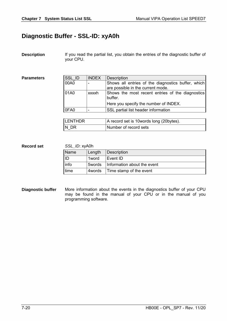
Chapter 7 System Status List SSL Manual VIPA Operation List SPEED7
7-20 HB00E - OPL_SP7 - Rev. 11/20
Diagnostic Buffer - SSL-ID: xyA0h
If you read the partial list, you obtain the entries of the diagnostic buffer of your CPU.
SSL_ID INDEX Description 00A0 - Shows all entries of the diagnostics buffer, which
are possible in the current mode. 01A0 xxxxh Shows the most recent entries of the diagnostics
buffer. Here you specify the number of INDEX.
0FA0 - SSL partial list header information LENTHDR A record set is 10words long (20bytes). N_DR Number of record sets
SSL_ID: xyA0h Name Length Description ID 1word Event ID info 5words Information about the event time 4words Time stamp of the event
More information about the events in the diagnostics buffer of your CPU may be found in the manual of your CPU or in the manual of you programming software.
Description
Parameters
Record set
Diagnostic buffer

Manual VIPA Operation List SPEED7 Chapter 7 System Status List SSL
HB00E - OPL_SP7 - Rev. 11/20 7-21
Diagnostic Information - SSL-ID: 00B1h
If you read this partial list, you obtain the first 4 diagnostic bytes of a module with diagnostic capability. SSL_ID INDEX Description 00B1h adr Shows the first 4 diagnostic bytes of a module.
Here the following is to be specified via INDEX: Bit 14 ... 0: Logical base address of the module Bit 15: 0: input, 1: output
LENTHDR A record set is 2words long (4bytes). N_DR 1 (Number of record sets) SSL_ID: 00B1h Name Length Description byte0 1byte Bit 0: Module fault (group fault ID)
Bit 1: Internal fault Bit 2: External fault Bit 3: Channel error exists Bit 4: No external auxiliary voltage Bit 5: No front connector Bit 6: Module not assigned parameters Bit 7: Wrong parameters on module
byte1 1byte Bit 3 ... 0: Module class 0000: CPU 0101: Analog modules 1000: FM 1100: CP 1111: Digital modules 0011: DP Norm slave 0100: IM Bit 4: Channel information exists Bit 5: User information exists Bit 6: Diagnostic interrupt from substitute Bit 7: Maintenance requirement (PROFINET IO only)
byte2 1byte Bit 0: User module incorrect/does not exist Bit 1: Communication fault Bit 2: Mode 0: RUN, 1: STOP Bit 3: Watchdog responded Bit 4: Internal module power supply failed Bit 5: Battery exhausted (BFS) Bit 6: Entire buffer failed Bit 7: Maintenance requirement (PROFINET IO only)
byte3 1byte Bit 0: Expansion rack failure (detected by IM) Bit 1: Processor failure Bit 2: EPROM error Bit 3: RAM error Bit 4: ADC/DAC error Bit 5: Fuse blown Bit 6: Hardware error lost Bit 7: reserved (fix 0)
Description
Parameters
Record set

Chapter 7 System Status List SSL Manual VIPA Operation List SPEED7
7-22 HB00E - OPL_SP7 - Rev. 11/20
Diagnostic Record set 1 - SSL-ID: 00B2h
If you read this partial list, you obtain the diagnostic record set 1 of a module in a central rack (not for PROFIBUS DP or submodules). The module is to be specified via rack and slot number.
SSL_ID INDEX Description 00B2h xxyyh Shows diagnostic record set 1 of a module.
Here the following is to be specified via INDEX: xx: Number of the rack yy: Slot number of the module
LENTHDR The length of the record set depends on the
module. N_DR 1 (Number of record set)
Information to length and structure of the diagnostic record set may be found in the corresponding manual of your diagnosticable module.
Description
Parameters
Record set
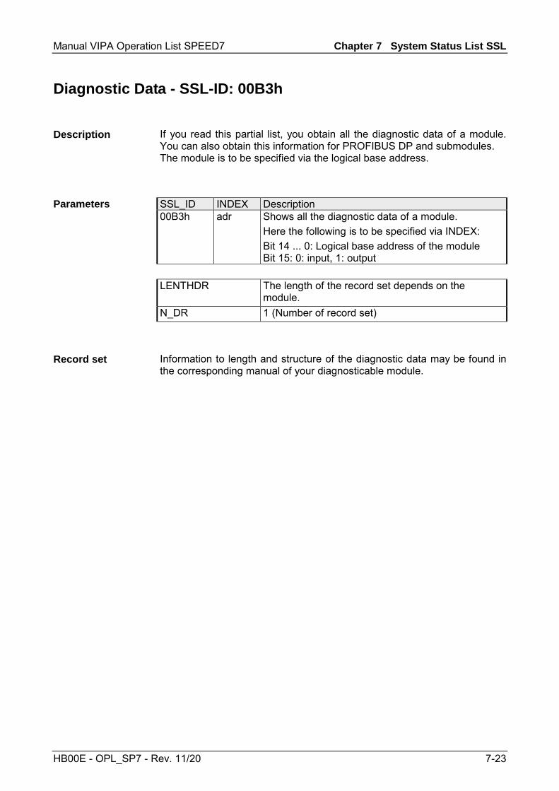
Manual VIPA Operation List SPEED7 Chapter 7 System Status List SSL
HB00E - OPL_SP7 - Rev. 11/20 7-23
Diagnostic Data - SSL-ID: 00B3h
If you read this partial list, you obtain all the diagnostic data of a module. You can also obtain this information for PROFIBUS DP and submodules. The module is to be specified via the logical base address.
SSL_ID INDEX Description 00B3h adr Shows all the diagnostic data of a module.
Here the following is to be specified via INDEX: Bit 14 ... 0: Logical base address of the module Bit 15: 0: input, 1: output
LENTHDR The length of the record set depends on the
module. N_DR 1 (Number of record set)
Information to length and structure of the diagnostic data may be found in the corresponding manual of your diagnosticable module.
Description
Parameters
Record set

Chapter 7 System Status List SSL Manual VIPA Operation List SPEED7
7-24 HB00E - OPL_SP7 - Rev. 11/20
Diagnostic Data of a DP slave - SSL-ID: 00B4h
If you read this partial list, you obtain the diagnostic data of a PROFIBUS DP slave. This diagnostic data is structured in compliance with EN 50 170 Volume 2, PROFIBUS. The module is to be specified via the configured diagnostic address.
SSL_ID INDEX Description 00B4h diagadr Shows all the diagnostic data of a PROFIBUS DP
slave. Here the configured diagnostic address of the DP slave is to be specified with INDEX.
LENTHDR Length of a record set
The maximum length is 240bytes. For standard slaves, which have a diagnostic data length of more than 240bytes up to a maximum of 244bytes, the first 240bytes are read and the overflow bit is set in the data.
N_DR 1 (Number of record set)
SSL_ID: 00B4h Name Length Description status1 1byte Station status 1 status2 1byte Station status 2 status3 1byte Station status 3 stat_nr 1byte Number of master station ken_hi 1byte Vendor ID (high byte) ken_lo 1byte Vendor ID (low byte) ... ... Further diagnostic data specific to the particular slave
Description
Parameters
Record set