hb160e tp-eco | re 62h-mdc0 | rev. 12/49 december 2012 · ... slio, system 100v, system 200v,...
TRANSCRIPT

VIPA HMI
Touch Panel | 62H-MDC0 | Manual HB160E_TP-ECO | RE_62H-MDC0 | Rev. 12/49
December 2012

Copyright © VIPA GmbH. All Rights Reserved.
This document contains proprietary information of VIPA and is not to be disclosed or used except in accordance with applicable agreements.
This material is protected by the copyright laws. It may not be reproduced, distributed, or altered in any fashion by any entity (either internal or external to VIPA), except in accordance with applicable agreements, contracts or licensing, without the express written consent of VIPA and the business management owner of the material.
For permission to reproduce or distribute, please contact: VIPA, Gesellschaft für Visualisierung und Prozessautomatisierung mbH Ohmstraße 4, D-91074 Herzogenaurach, Germany Tel.: +49 (91 32) 744 -0 Fax.: +49 9132 744 1864 EMail: [email protected] http://www.vipa.com Note
Every effort has been made to ensure that the information contained in this document was complete and accurate at the time of publishing. Nevertheless, the authors retain the right to modify the information. This customer document describes all the hardware units and functions known at the present time. Descriptions may be included for units which are not present at the customer site. The exact scope of delivery is described in the respective purchase contract.
CE Conformity Declaration
Hereby, VIPA GmbH declares that the products and systems are in compliance with the essential requirements and other relevant provisions.
Conformity is indicated by the CE marking affixed to the product.
Conformity Information
For more information regarding CE marking and Declaration of Conformity (DoC), please contact your local VIPA customer service organization.
Trademarks
VIPA, SLIO, System 100V, System 200V, System 300V, System 300S, System 400V, System 500S and Commander Compact are registered trademarks of VIPA Gesellschaft für Visualisierung und Prozessautomatisierung mbH.
SPEED7 is a registered trademark of profichip GmbH.
SIMATIC, STEP, SINEC, TIA Portal, S7-300 and S7-400 are registered trademarks of Siemens AG.
Microsoft und Windows are registered trademarks of Microsoft Inc., USA.
Portable Document Format (PDF) and Postscript are registered trademarks of Adobe Systems, Inc.
All other trademarks, logos and service or product marks specified herein are owned by their respective companies.
Information product support
Contact your local VIPA Customer Service Organization representative if you wish to report errors or questions regarding the contents of this document. If you are unable to locate a customer service center, contact VIPA as follows:
VIPA GmbH, Ohmstraße 4, 91074 Herzogenaurach, Germany
Telefax:+49 9132 744 1204 EMail: [email protected]
Technical support
Contact your local VIPA Customer Service Organization representative if you encounter problems with the product or have questions regarding the product. If you are unable to locate a customer service center, contact VIPA as follows:
VIPA GmbH, Ohmstraße 4, 91074 Herzogenaurach, Germany
Telephone: +49 9132 744 1150 (Hotline) EMail: [email protected]

Manual VIPA HMI Contents
HB160E - TP-ECO - RE_62H-MDC0 - Rev. 12/49 i
Contents About this manual .................................................................................... 1 Safety information.................................................................................... 2 Chapter 1 Hardware description ..................................................... 1-1
Safety information for Users................................................................. 1-2 Properties............................................................................................. 1-3 Structure .............................................................................................. 1-4 Components......................................................................................... 1-6 Dimensions .......................................................................................... 1-9 Technical Data ................................................................................... 1-10
Chapter 2 Deployment Touch Panel ............................................... 2-1 Installation............................................................................................ 2-2 Installation of the optional MPI/PROFIBUS DP interface...................... 2-4 Commissioning..................................................................................... 2-6 Connection to a PLC system.............................................................. 2-11 Operating system Windows® Embedded CE 6.0 Core ....................... 2-12 Integrated Server ............................................................................... 2-18 Access to the network resources........................................................ 2-22
Chapter 3 Installation Guidelines.................................................... 3-1 Basic rules for the EMC-equitable assembly of installations................. 3-2 EMC-equitable assembly...................................................................... 3-6 EMC-equitable cabling ......................................................................... 3-7 Special precautions providing high noise immunity ............................ 3-11 Checklist for the EMC-compliant installation of controllers ................. 3-12
Contents Manual VIPA HMI
ii HB160E - TP-ECO - RE_62H-MDC0 - Rev. 12/49

Manual VIPA HMI About this manual
HB160E - TP-ECO - RE_62H-MDC0 - Rev. 12/49 1
About this Manual
The manual describes the Touch Panel TP 607LC from VIPA. Here you find detailed descriptions of the Touch Panel beside a product overview. You get information about structure, project engineering and operation of the Touch panels from VIPA.
Chapter 1: Hardware description During this chapter you get hints for deployment of the Touch Panel TP 607LC from VIPA. Besides of a description of the single components of the Touch Panel, you will also find the dimensions that are required for the installation. The chapter closes with the technical data.
Chapter 2: Deployment Touch Panel This chapter deals with the application of the Touch Panel. At the beginning of the chapter you get information about the assembly and the connection of the Touch Panel. The main part of the chapter introduces Windows® CE and the various communication options offered by the Touch Panel.
Chapter 3: Installation guidelines The chapter "Installation Guidelines" gives you information about the interference-free installation of Programmable Logic Controls (PLC) together with a Touch Panel. Here we describe possible paths how interference can enter the controller, how you ensure the electromagnetic compatibility (EMC) and how to approach shielding and screening issues.
Overview

About this manual Manual VIPA HMI
2 HB160E - TP-ECO - RE_62H-MDC0 - Rev. 12/49
This manual describes the Touch Panel TP 607LC from VIPA. The manual consists of chapters. Every chapter provides the description of one specific topic. It describes the installation, project engineering, usage and the technical data. This manual is part of the documentation package with order number VIPA HB160E_TP-ECO and relevant for: Product Order number as of state: HW OS TP 607LC VIPA 62H-MDC0 01 Windows® CE 6.0 core This manual provides the following guides: • An overall table of contents at the beginning of the manual • An overview of the topics for every chapter The manual is available in: • printed form, on paper • in electronic form as PDF-file (Adobe Acrobat Reader) [Button] Buttons are put in brackets e.g. [NEXT] or [OK].
[Key] Key entry are put in brackets e.g. [STRG]+[A]. Display output
Display outputs are illustrated as Courier e.g.\flashdisk>
Keyboard entry
Keyboard entries are illustrated as Courier bold e.g. \flashdisk> Dir
Terms Menus, Display elements, terms are italics. Important passages in the text are highlighted by following icons and headings:
Danger! Immediate or likely danger. Personal injury is possible.
Attention! Damages to property is likely if these warnings are not heeded.
Note! Supplementary information and useful tips.
Objective and contents
Guide to the document
Availability
Description conventions
Icons Headings

Manual VIPA HMI Safety information
HB160E - TP-ECO - RE_62H-MDC0 - Rev. 12/49 3
Safety information
The Touch Panels are constructed and manufactured for: • VIPA CPUs 11x, 21x, 31x, 51x and S7-300/400 from Siemens • communication and process control • general control and automation applications • industrial applications • operation within the environmental conditions specified in the technical
data • installation into a cubicle
Danger! This device is not certified for applications in • in explosive environments (EX-zone)
The manual must be available to all personnel in the • project design department • installation department • commissioning • operation
The following conditions must be met before using or commissioning the components described in this manual: • Modification to the process control system should only be carried out
when the system has been disconnected from power! • Installation and modifications only by properly trained personnel • The national rules and regulations of the respective country must be
satisfied (installation, safety, EMC ...)
National rules and regulations apply to the disposal of the unit!
Applications conforming with specifications
Documentation
Disposal

Safety information Manual VIPA HMI
4 HB160E - TP-ECO - RE_62H-MDC0 - Rev. 12/49

Manual VIPA HMI Chapter 1 Hardware description
HB160E - TP-ECO - RE_62H-MDC0 - Rev. 12/49 1-1
Chapter 1 Hardware description
During this chapter you get hints for deployment of the Touch Panel TP 607LC from VIPA. Besides of a description of the single components of the Touch Panel, you will also find the dimensions that are required for the installation. The chapter closes with the technical data.
Topic Page Chapter 1 Hardware description...................................................... 1-1
Safety information for Users ................................................................. 1-2 Properties............................................................................................. 1-3 Structure .............................................................................................. 1-4 Components......................................................................................... 1-6 Dimensions .......................................................................................... 1-9 Technical Data ................................................................................... 1-10
Overview
Content

Chapter 1 Hardware description Manual VIPA HMI
1-2 HB160E - TP-ECO - RE_62H-MDC0 - Rev. 12/49
Safety information for Users
VIPA modules make use of highly integrated components in MOS-technology. These components are extremely sensitive to over-voltages that can occur during electrostatic discharges. The following symbol is attached to modules that can be destroyed by electrostatic discharges:
The symbol is located on the module, the module rack or on packing material and it indicates the presence of electrostatic sensitive equipment. It is possible that electrostatic sensitive equipment is destroyed by energies and voltages that are far less than the human threshold of perception. These voltages can occur where persons do not discharge themselves before handling electrostatic sensitive modules and they can damage components thereby, causing the module to become inoperable or unusable. Modules that have been damaged by electrostatic discharges may fail after a temperature change, mechanical shock or changes in the electrical load. Only the consequent implementation of protection devices and meticulous attention to the applicable rules and regulations for handling the respective equipment can prevent failures of electrostatic sensitive modules.
Modules have to be shipped in the original packing material.
When you are conducting measurements on electrostatic sensitive modules you should take the following precautions: • Floating instruments must be discharged before use. • Instruments must be grounded. Modifying electrostatic sensitive modules you should only use soldering irons with grounded tips. Attention! Personnel and instruments should be grounded when working on electrostatic sensitive modules.
Handling of electrostatic sensitive modules
Shipping of electrostatic sensitive modules
Measurements and alterations on electrostatic sensitive modules

Manual VIPA HMI Chapter 1 Hardware description
HB160E - TP-ECO - RE_62H-MDC0 - Rev. 12/49 1-3
Properties
The Touch Panel allows you to visualize and alter operating states and recent process values of a connected PLC.
The VIPA Touch Panel is a compact and modular embedded PC based on Windows® CE. Besides of the extensive Windows® CE functions the Touch Panel offers varied communication possibilities. Here the Touch Panel can simply be configured, controlled and remoted. By including a selectable HMI/SCADA runtime the Touch Panel is particularly suitable for monitoring and controlling of process cycles. • Windows® CE 6.0 Core • Movicon Basic • Processor ARM11, 533MHz • Flash memory 128Mbyte, RAM 128Mbyte • SD card slot • RS232, RS232/RS422/RS485, USB-A and Ethernet interface • MPI/PROFIBUS DP interface (optional) • Robust plastic case • display resolution 480 x 800 / 800 x 480 • battery backed clock • resistive analog touch screen • easy mounting via 6 mounting clips • protection class IP65 (frontal)
Type Order number Description TP 607LC VIPA 62H-MDC0 7" TFT color, RS232, RS232/RS422/RS485, USB-A,
Ethernet RJ45 MPI/PROFIBUS DP interface
VIPA 961-0MP0 MPI/PROFIBUS DP interface (optional)
General
TP 607LC 62H-MDC0
Order data
Chapter 1 Hardware description Manual VIPA HMI
1-4 HB160E - TP-ECO - RE_62H-MDC0 - Rev. 12/49
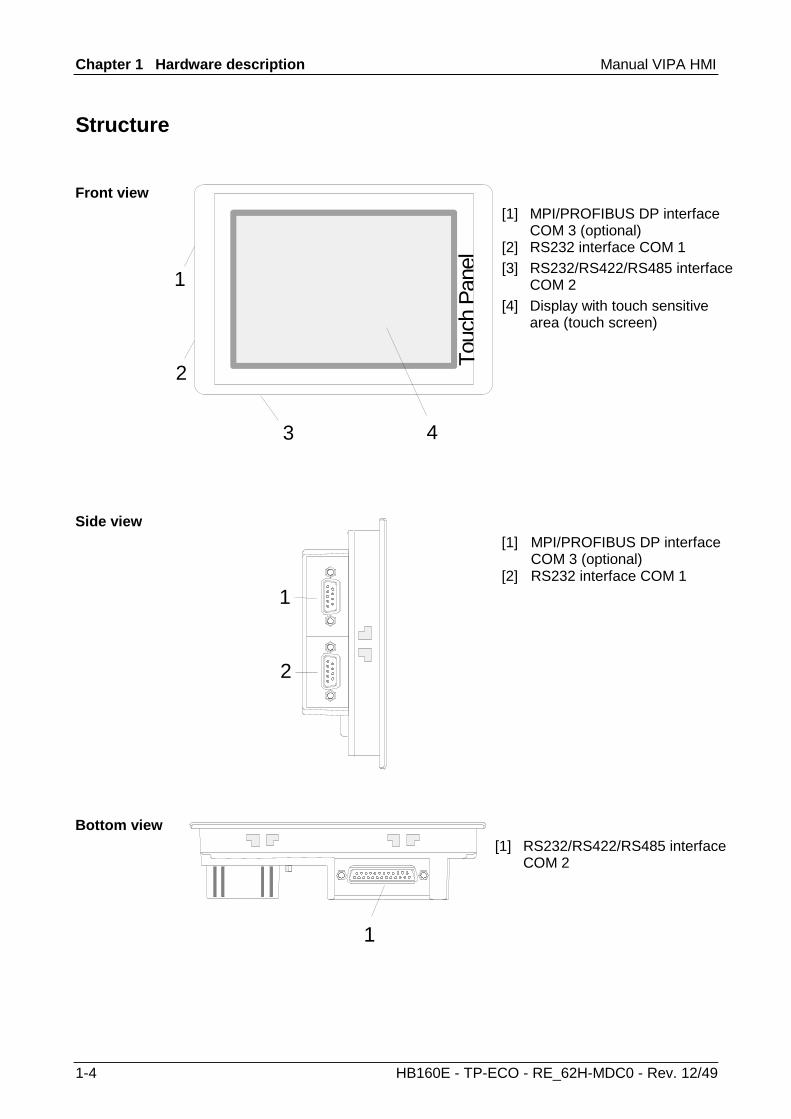
Structure
[1] MPI/PROFIBUS DP interface
COM 3 (optional) [2] RS232 interface COM 1 [3] RS232/RS422/RS485 interface
COM 2
Touc
h Pa
nel
4
2
3
1[4] Display with touch sensitive
area (touch screen)
[1] MPI/PROFIBUS DP interface
COM 3 (optional) [2] RS232 interface COM 1
2
1
[1] RS232/RS422/RS485 interface
COM 2
1
Front view
Side view
Bottom view

Manual VIPA HMI Chapter 1 Hardware description
HB160E - TP-ECO - RE_62H-MDC0 - Rev. 12/49 1-5
2
3
1
LAN
11-36VDC+-
CO
M3
COM2
CO
M1
SD
4 [1] Slot for SD storage medium [2] RJ45 jack for Ethernet communication [3] Slot for DC 24V voltage supply [4] "Host"-USB-A interface
Note! Please regard that the Touch Panel always has to be supplied with external voltage!
Back view
Chapter 1 Hardware description Manual VIPA HMI
1-6 HB160E - TP-ECO - RE_62H-MDC0 - Rev. 12/49
Components
The following memory systems are available for every Touch Panel: • 128Mbyte work memory • 128Mbyte Flash disk (50Mbyte for user data) • USB storage media using "Host"-USB-A interface • Slot for SD Every Touch Panel has a work memory with a size of 128Mbyte. The work memory is not buffered and is deleted after shut down. Please regard that also registry entries are stored in the work memory that are set back to default settings after the next re-boot. As internal permanent storage medium every Touch Panel has a flash disk with a size of 128Mbyte (50Mbyte user data). After the start of Windows® CE this memory is listed as Flashdisk at My Device. The connection of USB sticks and USB drives by use of the "Host"-USB-A interface is supported by the Touch Panel. After connection the storage media is listed as Hard Disk at My Device. At the back of the Touch Panel there are the card slots for memory cards. At this slot you may plug storage modules of the type SD. The card may be plugged and removed during runtime and is immediately listed as SDMMC Card at My Device.
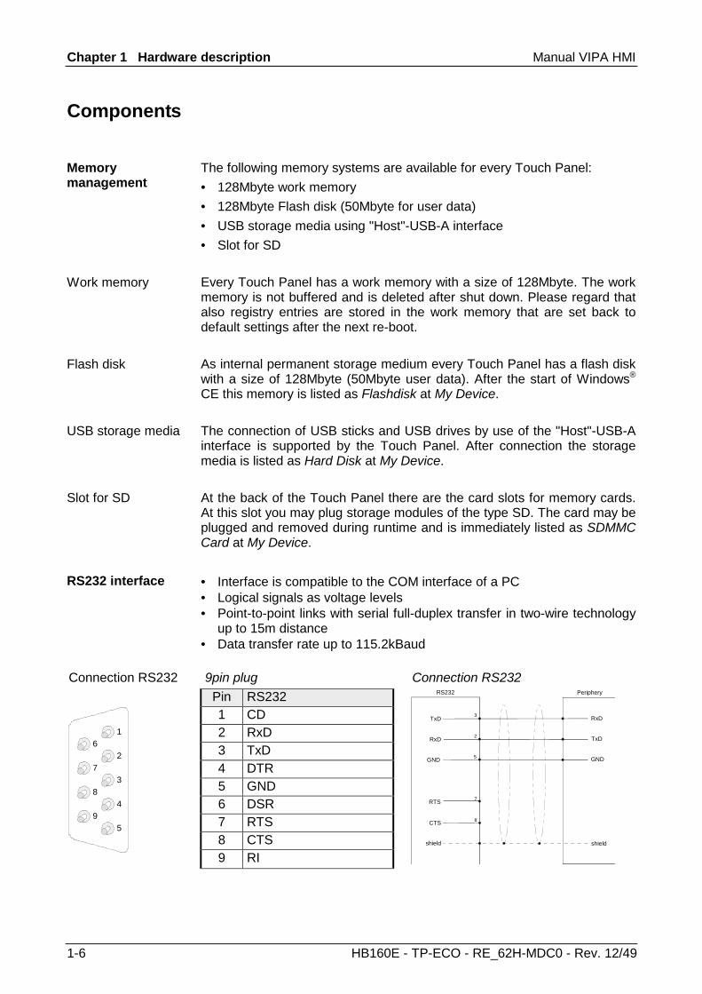
• Interface is compatible to the COM interface of a PC • Logical signals as voltage levels • Point-to-point links with serial full-duplex transfer in two-wire technology
up to 15m distance • Data transfer rate up to 115.2kBaud
Connection RS232 9pin plug Connection RS232 Pin RS232 1 CD 2 RxD 3 TxD 4 DTR 5 GND 6 DSR 7 RTS 8 CTS
1
2
3
4
5
6
7
8
9
9 RI
RxD
TxD
GND
TxD
RxD
3
2
GND 5
RTS
CTS
7
8
shield
RS232 Periphery
shield
Memory management
Work memory
Flash disk
USB storage media
Slot for SD
RS232 interface
Manual VIPA HMI Chapter 1 Hardware description
HB160E - TP-ECO - RE_62H-MDC0 - Rev. 12/49 1-7
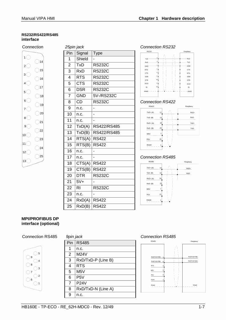
Connection 25pin jack Connection RS232 Pin Signal Type 1 Shield - 2 TxD RS232C 3 RxD RS232C 4 RTS RS232C 5 CTS RS232C 6 DSR RS232C 7 GND 5V-/RS232C
RxD
TxD
GND
TxD
RxD
2
3
GND 7
DCD
RI
shield
RS232 Periphery
shield
4
5
RTS
CTS
6DSR
20DTR
8
22
CTS
RTS
DSR
DTR
DCD
RI
8 CD RS232C Connection RS422 9 n.c. - 10 n.c. - 11 n.c. - 12 TxD(A) RS422/RS485 13 TxD(B) RS422/RS485 14 RTS(A) RS422 15 RTS(B) RS422 16 n.c. -
TxD+ (A)
TxD- (B)
RxD+ (A)
RxD- (B)
Shield
RS422 Periphery
12
13
24
25
M5V
TxD+
TxD-
RxD+
RxD-
P5V
7
21
1
17 n.c. - Connection RS485 18 CTS(A) RS422 19 CTS(B) RS422 20 DTR RS232C 21 5V+ - 22 RI RS232C 23 n.c. - 24 RxD(A) RS422
142
3
4
5
6
7
8
9
10
11
12
13
15
16
17
18
19
20
21
22
23
24
25
1
25 RxD(B) RS422
TxD+ (A)
TxD- (B)
RxD+ (A)
RxD- (B)
Shield
RS485 Periphery
12
13
24
25
M5V
RxD+
RxD-
P5V
7
21
1
Connection RS485 9pin jack Connection RS485 Pin RS485 1 n.c. 2 M24V 3 RxD/TxD-P (Line B) 4 RTS 5 M5V 6 P5V 7 P24V 8 RxD/TxD-N (Line A)
5
4
3
2
1
9
8
7
6
9 n.c.
RxD/TxD-P(B)
Shield
RS485
3
8
P24V
RxD/TxD-P(B)
5
RxD/TxD-P(B)
RxD/TxD-N(A)
Periphery
P5V
M5V
RTS 4
6
7
Shield
RS232/RS422/RS485interface
MPI/PROFIBUS DP interface (optional)

Chapter 1 Hardware description Manual VIPA HMI
1-8 HB160E - TP-ECO - RE_62H-MDC0 - Rev. 12/49
An RJ45 jack provides the interface to the twisted pair cable, required for Ethernet. The pin assignment of this jack is as follows: 8pin RJ45 jack
Pin Signal 1 Transmit + 2 Transmit - 3 Receive + 4 - 5 - 6 Receive - 7 -
8 -
Using the "Host"-USB-A interface mouse, keyboard, USB stick or USB hard discs can be connected. The pin assignment is as follows: "Host"-USB-A:
Pin Assignment 1 VCC 2 DM 3 DP 1
2
3
4
4 GND
The Touch Panel has got an integrated power supply. The power supply has to be provided with DC 24V (20.4 ... 28.8V). For this you find an according DC 24V slot at the back.
DC 24V
The power supply is protected against inverse polarity and overcurrent.
Ethernet connection
12345678
"Host"-USB-A
Power supply
Manual VIPA HMI Chapter 1 Hardware description
HB160E - TP-ECO - RE_62H-MDC0 - Rev. 12/49 1-9
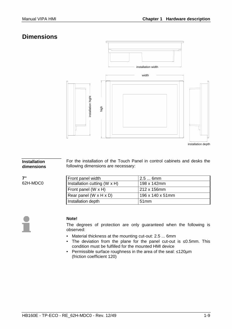
Dimensions
installation width
inst
alla
tion
high
t
installation depth
width
high
For the installation of the Touch Panel in control cabinets and desks the following dimensions are necessary: Front panel width 2.5 ... 6mm Installation cutting (W x H) 198 x 142mm Front panel (W x H) 212 x 156mm Rear panel (W x H x D) 196 x 140 x 51mm Installation depth 51mm
Note! The degrees of protection are only guaranteed when the following is observed: • Material thickness at the mounting cut-out: 2.5 ... 6mm • The deviation from the plane for the panel cut-out is ≤0.5mm. This
condition must be fulfilled for the mounted HMI device • Permissible surface roughness in the area of the seal: ≤120µm
(friction coefficient 120)
Installation dimensions
7'' 62H-MDC0
Chapter 1 Hardware description Manual VIPA HMI
1-10 HB160E - TP-ECO - RE_62H-MDC0 - Rev. 12/49
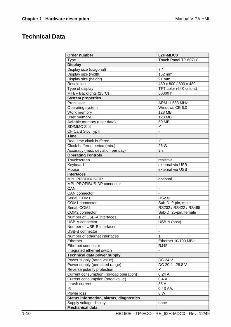
Technical Data
Order number 62H-MDC0 Type Touch Panel TP 607LC Display Display size (diagonal) 7 " Display size (width) 152 mm Display size (height) 91 mm Resolution 480 x 800 / 800 x 480 Type of display TFT color (64K colors) MTBF Backlights (25°C) 50000 h System properties Processor ARM11 533 MHz Operating system Windows CE 6.0 Work memory 128 MB User memory 128 MB Avilable memory (user data) 50 MB SD/MMC Slot CF Card Slot Typ II - Time Real-time clock buffered Clock buffered period (min.) 26 W Accuracy (max. deviation per day) 2 s Operating controls Touchscreen resistive Keyboard external via USB Mouse external via USB Interfaces MPI, PROFIBUS-DP optional MPI, PROFIBUS-DP connector - CAN - CAN connector - Serial, COM1 RS232 COM1 connector Sub-D, 9-pin, male Serial, COM2 RS232 / RS422 / RS485 COM2 connector Sub-D, 25-pin, female Number of USB-A interfaces 1 USB-A connector USB-A (host) Number of USB-B interfaces - USB-B connector - Number of ethernet interfaces 1 Ethernet Ethernet 10/100 MBit Ethernet connector RJ45 Integrated ethernet switch - Technical data power supply Power supply (rated value) DC 24 V Power supply (permitted range) DC 20.4...28.8 V Reverse polarity protection Current consumption (no-load operation) 0.24 A Current consumption (rated value) 0.4 A Inrush current 85 A I²t 0.43 A²s Power loss 8 W Status information, alarms, diagnostics Supply voltage display none Mechanical data
Manual VIPA HMI Chapter 1 Hardware description
HB160E - TP-ECO - RE_62H-MDC0 - Rev. 12/49 1-11
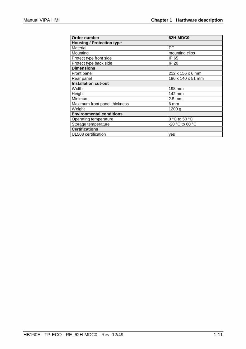
Order number 62H-MDC0 Housing / Protection type Material PC Mounting mounting clips Protect type front side IP 65 Protect type back side IP 20 Dimensions Front panel 212 x 156 x 6 mm Rear panel 196 x 140 x 51 mm Installation cut-out Width 198 mm Height 142 mm Minimum 2.5 mm Maximum front panel thickness 6 mm Weight 1200 g Environmental conditions Operating temperature 0 °C to 50 °C Storage temperature -20 °C to 60 °C Certifications UL508 certification yes

Chapter 1 Hardware description Manual VIPA HMI
1-12 HB160E - TP-ECO - RE_62H-MDC0 - Rev. 12/49
Manual VIPA HMI Chapter 2 Deployment Touch Panel
HB160E - TP-ECO - RE_62H-MDC0 - Rev. 12/49 2-1
Chapter 2 Deployment Touch Panel
This chapter deals with the application of the Touch Panel. At the beginning of the chapter you get information about the assembly and the connection of the Touch Panel. The main part of the chapter introduces Windows® CE and the various communication options offered by the Touch Panel.
Topic Page Chapter 2 Deployment Touch Panel ............................................... 2-1
Installation............................................................................................ 2-2 Installation of the optional MPI/PROFIBUS DP interface...................... 2-4 Commissioning..................................................................................... 2-6 Connection to a PLC system.............................................................. 2-11 Operating system Windows® Embedded CE 6.0 Core ....................... 2-12 Integrated Server ............................................................................... 2-18 Access to the network resources........................................................ 2-22
Overview
Content

Chapter 2 Deployment Touch Panel Manual VIPA HMI
2-2 HB160E - TP-ECO - RE_62H-MDC0 - Rev. 12/49
Installation
The Touch Panel is suitable for the installation in operating tables and control cabinet fronts. The installation happens via the backside. The Touch Panel is provided with a patented integrated fixing technique that allows an easy connection with a hexagon socket key. A fast and easy device change is possible. For the installation into a operating tableau and control cabinet fronts, the Touch Panel requires the following front plate cutting:
W
H
Touch Panel W x H in mm 62H-MDC0 198 x 142mm
For the installation of the panel, 6 mounting clips and a small hexagon socket key are required. Push the operator panel [3] from the front side into the front panel cutting [1] until it touches the panel with the seal [2]. Put the mounting clips [4] on all four sides of the panel into the openings. The screws should point in the direction of the front panel. Screw the screws from the other side with the hexagon socket key [5].
1
2 3
4
5
Overview
Installation cutting
Installation

Manual VIPA HMI Chapter 2 Deployment Touch Panel
HB160E - TP-ECO - RE_62H-MDC0 - Rev. 12/49 2-3
For the cabling of the DC 24V power supply green plugs with CageClamp technology are deployed. The spring-clip connector technology simplifies the wiring requirements for signaling and power cables. In contrast to screw terminal connections, spring-clip wiring is vibration proof. Here also you may connect wires with a cross-section of 0.08mm2 to 2.5mm2. You can use flexible wires without end case as well as stiff wires. Fix the conductors to the CageClamps like this:
1
2
3
DC 24V
[1] Round opening for wires [2] Locking (orange) for screwdriver [3] Test point for 2mm test tip
1
2
3
The picture on the left side shows the cabling step by step from top view. • For cabling you push the locking vertical to the inside with a suiting
screwdriver and hold the screwdriver in this position. • Insert the insulation-stripped wire into the round opening. You may use
wires with a cross-section from 0.08mm2 to 2.5mm2. • By removing the screwdriver the wire is connected safely with the plug
connector via a spring.
Connect power supply

Chapter 2 Deployment Touch Panel Manual VIPA HMI
2-4 HB160E - TP-ECO - RE_62H-MDC0 - Rev. 12/49
Installation of the optional MPI/PROFIBUS DP interface
Attention! Personnel and instruments should be grounded when working on electrostatic sensitive modules! Take the interface module only at the holding plate and avoid touching the board! Store respectively send the interface module always in the corresponding ESD packaging!
• Remove the cover plate of the COM3 port by removing the screws and pulling the plate.
• For installation insert the interface module into the opening. Push the
interface module in the device until the holding plate fits to the housing. Here the interface module is put into the right position by 2 inner guide rails.
Installation
Manual VIPA HMI Chapter 2 Deployment Touch Panel
HB160E - TP-ECO - RE_62H-MDC0 - Rev. 12/49 2-5
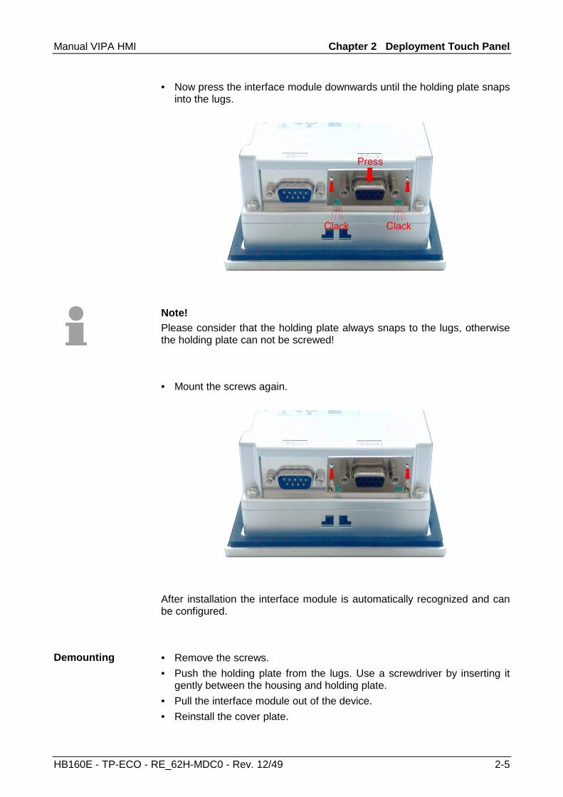
• Now press the interface module downwards until the holding plate snaps into the lugs.
Note! Please consider that the holding plate always snaps to the lugs, otherwise the holding plate can not be screwed!
• Mount the screws again.
After installation the interface module is automatically recognized and can be configured.
• Remove the screws. • Push the holding plate from the lugs. Use a screwdriver by inserting it
gently between the housing and holding plate. • Pull the interface module out of the device. • Reinstall the cover plate.
Demounting

Chapter 2 Deployment Touch Panel Manual VIPA HMI
2-6 HB160E - TP-ECO - RE_62H-MDC0 - Rev. 12/49
Commissioning
Attention! • Before commissioning the device must be brought to room temperature. • At condensation the device must be absolutely dry before connected to
power. • To avoid overheat during operation the device must not be laid open to
direct sun light. • After opening the control cabinet or desk, there are parts with possible
dangerous voltage available. • For all signal connections only screened cables are permitted. • Signal cables must not be let within the same cable shaft as high
voltage cables.
As soon as the Touch Panel is provided by power supply, the VIPA Startup-Manager will be loaded.
At the first startup of the VIPA Startup-Manager the following start screen appears. At this time no runtime and no project are preset.
With clicking to [Setting] the selection menu of the VIPA Startup-Manager is opened. With [Autostart] you may define the runtime and the project with which the Startup-Manager has to start in future.
VIPA Startup-Manager
Start screen Initialization
Manual VIPA HMI Chapter 2 Deployment Touch Panel
HB160E - TP-ECO - RE_62H-MDC0 - Rev. 12/49 2-7
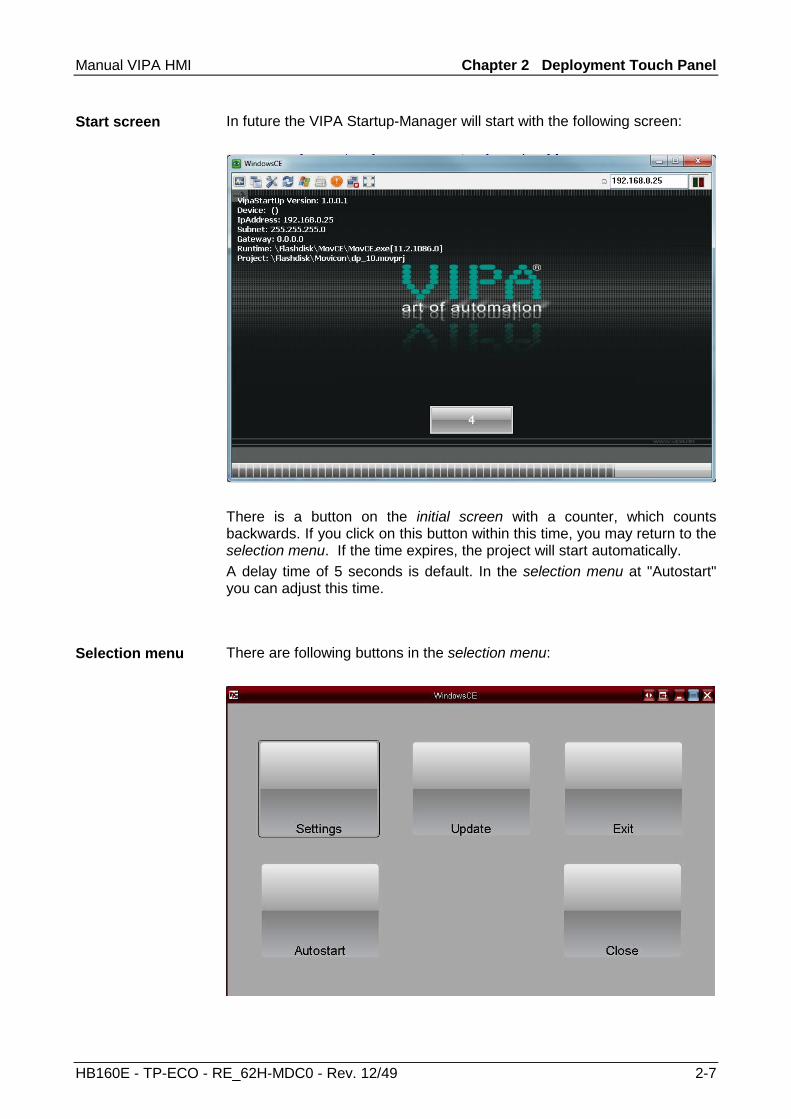
In future the VIPA Startup-Manager will start with the following screen:
There is a button on the initial screen with a counter, which counts backwards. If you click on this button within this time, you may return to the selection menu. If the time expires, the project will start automatically. A delay time of 5 seconds is default. In the selection menu at "Autostart" you can adjust this time.
There are following buttons in the selection menu:
Start screen
Selection menu

Chapter 2 Deployment Touch Panel Manual VIPA HMI
2-8 HB160E - TP-ECO - RE_62H-MDC0 - Rev. 12/49
In [Settings] the system settings like brightness and contrast of the display can be preset or the display can be re-calibrated. Here the MPI/DP slave interface may also be configured. Further you get here the Touch Panel information: product number, serial number and licenses.
To execute the firmware update press the button [Update]. After clicking on [Update] the current image is displayed under "image version" with panel name, creation date and version number.
With [search Image] a list of all the firmware images is shown, which are available on the panel and connected storage media. These images will be listed with create data and version number. Choose your new image.
Settings
Update (firmware)

Manual VIPA HMI Chapter 2 Deployment Touch Panel
HB160E - TP-ECO - RE_62H-MDC0 - Rev. 12/49 2-9
If the select image is not suited for your panel, an error massage appears. If the image is suited for your panel, in the following message the current installed image version and the new selected image version are listed. Click on [Make Image Update] to execute the update. This can take a few seconds.
In the following window click on [Finish] to end the update. Then the display gets dark.
Switch the power supply off the panel off and on. After the restart the calibration window is opened.
Update continued
Chapter 2 Deployment Touch Panel Manual VIPA HMI
2-10 HB160E - TP-ECO - RE_62H-MDC0 - Rev. 12/49
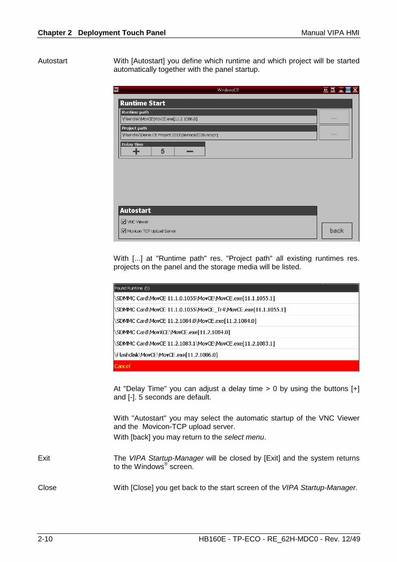
With [Autostart] you define which runtime and which project will be started automatically together with the panel startup.
With [...] at "Runtime path" res. "Project path" all existing runtimes res. projects on the panel and the storage media will be listed.
At "Delay Time" you can adjust a delay time > 0 by using the buttons [+] and [-]. 5 seconds are default. With "Autostart" you may select the automatic startup of the VNC Viewer and the Movicon-TCP upload server. With [back] you may return to the select menu. The VIPA Startup-Manager will be closed by [Exit] and the system returns to the Windows® screen. With [Close] you get back to the start screen of the VIPA Startup-Manager.
Autostart
Exit
Close

Manual VIPA HMI Chapter 2 Deployment Touch Panel
HB160E - TP-ECO - RE_62H-MDC0 - Rev. 12/49 2-11
Connection to a PLC system
For the inclusion into your PLC system several HMI/SCADA project-engineering platforms are at your disposal that has to be installed at an external PC. Here you may create your project, where appropriate simulate it and transfer it to the Touch Panel via a connection that you’ve entered before. Via the at the Touch Panel pre-installed runtime version of the HMI/SCADA project engineering platforms your project is run able. By using the according communication driver, the Touch Panel supports connecting options to the PLC via field bus and Ethernet. During operation your operating device communicates with the according PLC and reacts to the application courses in the PLC according to the configured processes. Via dialogs configured before, process values may be monitored graphically, altered and evaluated.
HMI/SCADA
Fieldbus,Ethernet
Touch Panel
ftp, VNC
SD
PC
...
CPU
SPS
CPU
SPS
...
Touc
h P
anel
HMI/SCADARuntime
- ftp-Server- VNC
Chapter 2 Deployment Touch Panel Manual VIPA HMI
2-12 HB160E - TP-ECO - RE_62H-MDC0 - Rev. 12/49
Operating system Windows® Embedded CE 6.0 Core
The newly developed standard Windows® CE allows devices that are communicating with each other to exchange information with Windows® based devices and to establish connections to the Internet. Microsoft Windows® CE is a 32bit, open and scalable platform for a multiplicity of communication and data processing devices. The functions like multi-tasking and multi-threading are supported by this operating system.
Windows® CE 6.0 Core is a Windows® operating system reduced to the absolute essentials with mouse operation (touch screen) that requires only small hardware resources.
• ftp and VNC server • Registry Editor • WordPad • Mouse pointer • USB keyboard driver • HP printer driver (COM, Ethernet, USB) • VIPA Startup Manager
General
Windows® Embedded CE 6.0 Core
Properties
Manual VIPA HMI Chapter 2 Deployment Touch Panel
HB160E - TP-ECO - RE_62H-MDC0 - Rev. 12/49 2-13
Please regard that for the deployment of Windows® CE a thorough knowledge of operating Windows® are assumed. Here are only shown the differences to a "standard" Windows® operating system. You’re operating the Touch Panel by means of a pencil res. with the finger. When touching an area at the touch screen this area is recognized and the program reacts accordingly. The following types of entry are differentiated: Double click A double click has to be executed like mouse operation by touching the area at the screen twice. A double click on an object opens res. executes this. Drag By tapping on an object and then dragging you may move the object on the screen. If no object is selected, a frame is created by the dragging that selects the touched objects. The windows may be moved via the head bar. Here you may also find the [OK] button to confirm entries and the [X] button for exiting the dialog. You may not exit Windows®. By switching the power supply off and on again you may restart Windows®. Before a reboot you should always save your data res. close all running applications to avoid data loss.
Note! Please consider that changes are stored automatically after 30 seconds. For manual storage, please use the "suspend" function. This may be found in the start menu.
Differences to the standard Windows® operation
Pen entry
Navigation within the dialog window
Exit Windows® (shut down)

Chapter 2 Deployment Touch Panel Manual VIPA HMI
2-14 HB160E - TP-ECO - RE_62H-MDC0 - Rev. 12/49
1
2 3
1 Icon Via icons on the desktop you gain direct access to the application related to the icon.
2 Desktop The desktop is the screen that is shown after login at Windows® CE. It contains e.g. links to the mostly used applications res. system components.
3 Task bar The task bar is part of the desktop. When opening an application, a document or a window, every running object is displayed as button on the task bar. Via this buttons you may easily change between the open windows. Basically the task bar has the following structure:
4 51 2 63
1 Start button This button offers you access to all components of your Touch Panel like e.g. applications, system settings, file browser etc.
2 Open applications
For every open application a button is to be found in the task bar. There is no button for minimizing. The switch between the applications is performed via this buttons.
3 Network connection
As soon as your Touch Panel is connected via Ethernet you can see here the Ethernet address. If there is no connection via Ethernet, the symbol is displayed crossed out.
4 Time This area shows the time that you may change via double click. 5 Show desktop All windows are minimized and the desktop is shown. 6 Software
keyboard This button displays a keyboard at the screen. "Hide Input Panel" hides the keyboard again.
Structure
Task bar

Manual VIPA HMI Chapter 2 Deployment Touch Panel
HB160E - TP-ECO - RE_62H-MDC0 - Rev. 12/49 2-15
The button allows you to select one of the available software keyboards. At the moment the following standard keyboards are implemented: Normal: At pushed SHIFT key:
At pushed [a´ü] key:
Note! Please regard that the umlauts äöü may exclusively entered via the software keyboard Keyboard. Normal:
At pushed SHIFT key:
Meaning: Home Position 1 End End BS Backspace up ↑ dn ↓ lt ← rt → pgup Page ↑ pgdn Page ↓ ins Insert del Delete Tab Tabulator Shift Caps/Lock
The software keyboard allows you to enter key entries without connecting an external keyboard. As soon as an entry is required the software keyboard is automatically shown. Hide Input Panel hides the keyboard again.
Software keyboard
Software keyboard Keyboard
Software keyboard Large KB
Hide keyboard

Chapter 2 Deployment Touch Panel Manual VIPA HMI
2-16 HB160E - TP-ECO - RE_62H-MDC0 - Rev. 12/49
Due to the fact that many components of the Control Panel are conform with the system control of Windows®, most of the description is here dispensed. The description of the control panel components relevant for operating the Touch Panel is to be found in the following:
Set display Via Start > Settings > Control Panel > Display the dialog windows for the display properties opens. Here you may change the settings for the monitor options. For example you may adjust the brightness and contrast via the register Settings.
Calibrate touch screen If your touch screen does not always react on a double click or recognizes the position of an entry not precisely, you may call the dialog Stylus via Start > Settings > Control Panel. In the register Double-Tap you may use the grid pattern to preset a double click velocity and test this on the symbol below. OK takes over the set value. The calibration of the touch screens happens via the register Calibration by following the instructions.
Set Ethernet parameters The dialog field for pre-setting an Ethernet address is to be found at Start > Settings > Network and Dial-up Connections. The default setting is address assignment via DHCP.
System properties (System) Here you receive information about the version of the current Windows® operating system, the memory load and sharing (alterations here are not taken over into the registry) and about the copyright. The register Device Name allows you to change the device name that is e.g. shown during Ethernet communication. Set the break time of the back-lighting Via Start > Settings > Control Panel > Power Properties you may set the break time of the back-lighting. For this choose AC Power at "Power Scheme" and then set the appropriate time at "Switch state to System Idle".
System setting (Control Panel)
Manual VIPA HMI Chapter 2 Deployment Touch Panel
HB160E - TP-ECO - RE_62H-MDC0 - Rev. 12/49 2-17
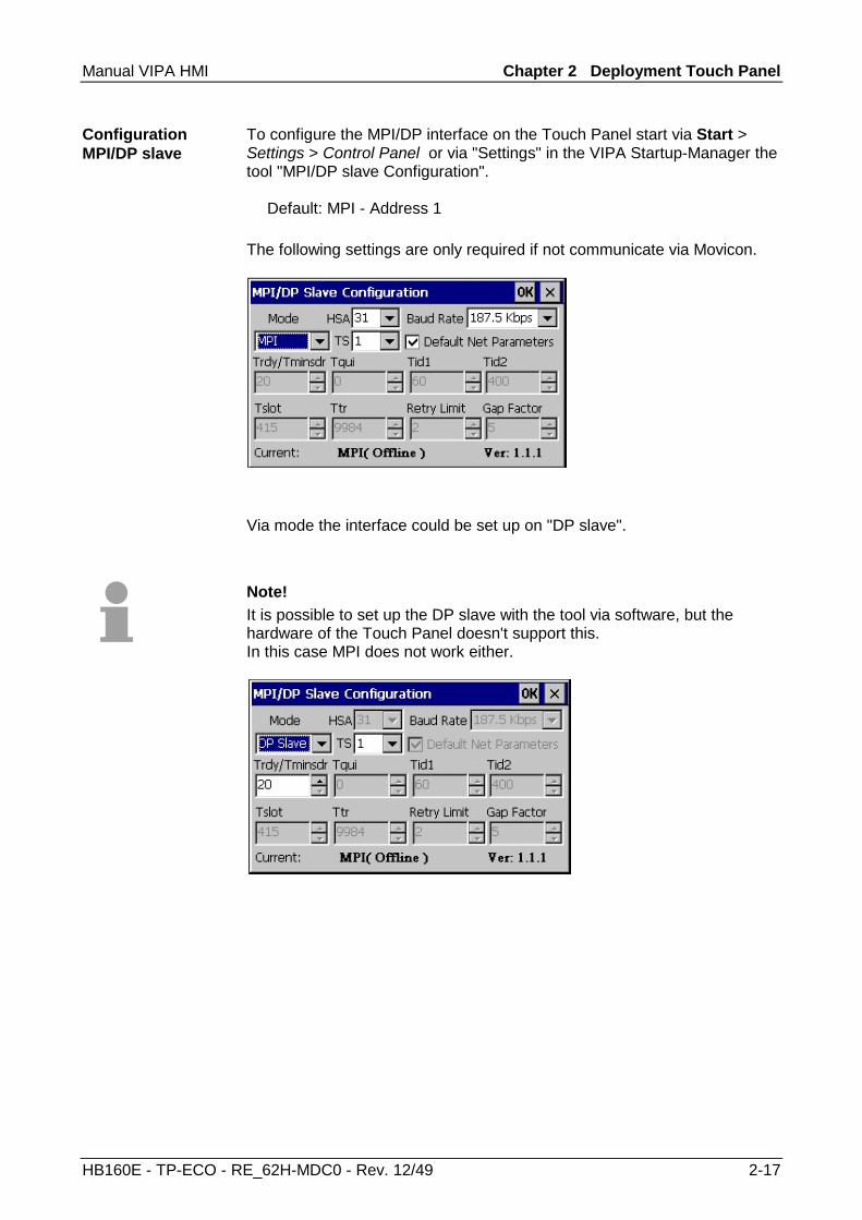
To configure the MPI/DP interface on the Touch Panel start via Start > Settings > Control Panel or via "Settings" in the VIPA Startup-Manager the tool "MPI/DP slave Configuration". Default: MPI - Address 1 The following settings are only required if not communicate via Movicon.
Via mode the interface could be set up on "DP slave".
Note! It is possible to set up the DP slave with the tool via software, but the hardware of the Touch Panel doesn't support this. In this case MPI does not work either.
Configuration MPI/DP slave

Chapter 2 Deployment Touch Panel Manual VIPA HMI
2-18 HB160E - TP-ECO - RE_62H-MDC0 - Rev. 12/49
Integrated Server
The Touch Panel has several integrated server that enable a remote maintenance within a network. Some servers only allow access by means of entering User name and Password. The following login data are used standardly: User name: wince Password: vipatp
Per default the following server are integrated: • ftp server (activated) • VNC (not activated)
Phrases that are used in the description of the server: A client is an application that uses the service of a server within a network. For example, a web browser is a client because at every call of a website it sends a request to a web server and receives an answer. A server is an application that waits for the contact request of a client application and exchanges messages with it after contact start. This communication type is called Client-Server communication. Computer within a network where at least one server is running. Data transfer Server → Client Data transfer Client → Server
Login data
Overview
Phrases
Client
Server
Host
Download
Upload
Manual VIPA HMI Chapter 2 Deployment Touch Panel
HB160E - TP-ECO - RE_62H-MDC0 - Rev. 12/49 2-19
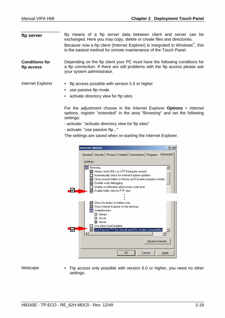
By means of a ftp server data between client and server can be exchanged. Here you may copy, delete or create files and directories. Because now a ftp client (Internet Explorer) is integrated in Windows®, this is the easiest method for remote maintenance of the Touch Panel. Depending on the ftp client your PC must have the following conditions for a ftp connection. If there are still problems with the ftp access please ask your system administrator. • ftp access possible with version 5.5 or higher • use passive ftp mode • activate directory view for ftp sites For the adjustment choose in the Internet Explorer Options > Internet options, register "extended" in the area "Browsing” and set the following settings: - activate: "activate directory view for ftp sites" - activate: "use passive ftp..." The settings are saved when re-starting the Internet Explorer.
• Ftp access only possible with version 6.0 or higher, you need no other
settings.
ftp server
Conditions for ftp access
Internet Explorer
Netscape
Chapter 2 Deployment Touch Panel Manual VIPA HMI
2-20 HB160E - TP-ECO - RE_62H-MDC0 - Rev. 12/49
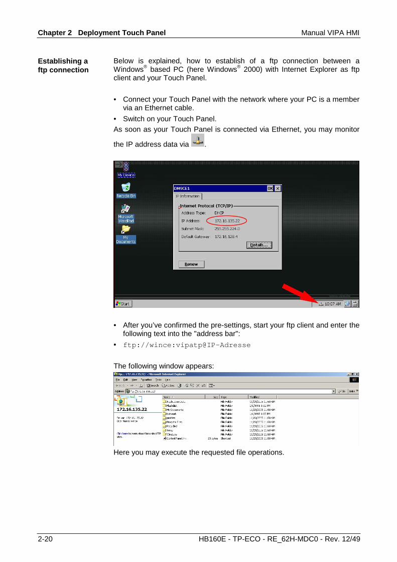
Below is explained, how to establish of a ftp connection between a Windows® based PC (here Windows® 2000) with Internet Explorer as ftp client and your Touch Panel. • Connect your Touch Panel with the network where your PC is a member
via an Ethernet cable. • Switch on your Touch Panel. As soon as your Touch Panel is connected via Ethernet, you may monitor
the IP address data via .
• After you’ve confirmed the pre-settings, start your ftp client and enter the
following text into the "address bar": • ftp://wince:vipatp@IP-Adresse
The following window appears:
Here you may execute the requested file operations.
Establishing a ftp connection
Manual VIPA HMI Chapter 2 Deployment Touch Panel
HB160E - TP-ECO - RE_62H-MDC0 - Rev. 12/49 2-21
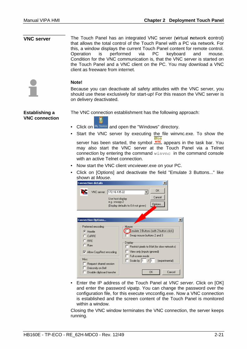
The Touch Panel has an integrated VNC server (virtual network control) that allows the total control of the Touch Panel with a PC via network. For this, a window displays the current Touch Panel content for remote control. Operation is performed via PC keyboard and mouse. Condition for the VNC communication is, that the VNC server is started on the Touch Panel and a VNC client on the PC. You may download a VNC client as freeware from internet. Note! Because you can deactivate all safety attitudes with the VNC server, you should use these exclusively for start-up! For this reason the VNC server is on delivery deactivated. The VNC connection establishment has the following approach:
• Click on and open the "Windows" directory. • Start the VNC server by executing the file winvnc.exe. To show the
server has been started, the symbol appears in the task bar. You may also start the VNC server at the Touch Panel via a Telnet connection by entering the command winvnc in the command console with an active Telnet connection.
• Now start the VNC client vncviewer.exe on your PC. • Click on [Options] and deactivate the field "Emulate 3 Buttons..." like
shown at Mouse.
• Enter the IP address of the Touch Panel at VNC server. Click on [OK]
and enter the password vipatp. You can change the password over the configuration file, for this execute vncconfig.exe. Now a VNC connection is established and the screen content of the Touch Panel is monitored within a window.
Closing the VNC window terminates the VNC connection, the server keeps running.
VNC server
Establishing a VNC connection
Chapter 2 Deployment Touch Panel Manual VIPA HMI
2-22 HB160E - TP-ECO - RE_62H-MDC0 - Rev. 12/49
Access to the network resources
The Touch Panel allows you to access shared resources in a Microsoft network like drives and printer. Here you may assign existing public directories or printer in the network to local directories or printer in the Touch Panel. Condition for this is that you are logged in to the network with your user name and password. The assignment of a network resource is performed in the Touch Panel via the command console "Command Prompt". Start the command console with START > Programs > Command Prompt. The access to the network resource is performed with the commands Net view and Net use.
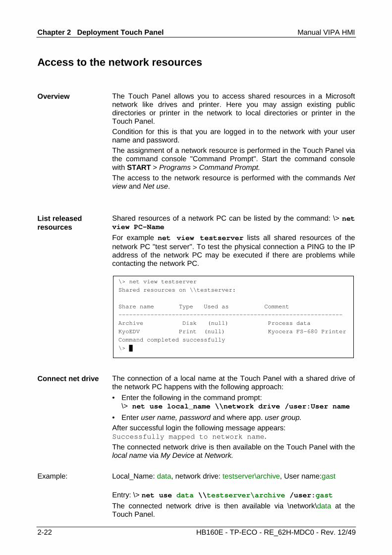
Shared resources of a network PC can be listed by the command: \> net view PC-Name For example net view testserver lists all shared resources of the network PC "test server". To test the physical connection a PING to the IP address of the network PC may be executed if there are problems while contacting the network PC.
The connection of a local name at the Touch Panel with a shared drive of the network PC happens with the following approach: • Enter the following in the command prompt:
\> net use local_name \\network drive /user:User name • Enter user name, password and where app. user group. After successful login the following message appears: Successfully mapped to network name. The connected network drive is then available on the Touch Panel with the local name via My Device at Network. Local_Name: data, network drive: testserver\archive, User name:gast Entry: \> net use data \\testserver\archive /user:gast The connected network drive is then available via \network\data at the Touch Panel.
Overview
List released resources
Connect net drive
Example:
\> net view testserver
Shared resources on \\testserver:
Share name Type Used as Comment
---------------------------------------------------------------
Archive Disk (null) Process data
KyoEDV Print (null) Kyocera FS-680 Printer
Command completed successfully
\> █
Manual VIPA HMI Chapter 2 Deployment Touch Panel
HB160E - TP-ECO - RE_62H-MDC0 - Rev. 12/49 2-23
The configuration of a network printer happens with the following approach: • Enter this command into the command prompt:
\> net use printer name network printer Example: Printer name: Printer, network printer: \\testserver\printer Entry: \> net use printer \\testserver\printer
• Enter user name, password and if necessary user group. After the successful login the following message appears Successfully mapped to network printer
The printer may now be accessed as "network\printer". For example you may print the content of the current directory using \> dir > network\printer.
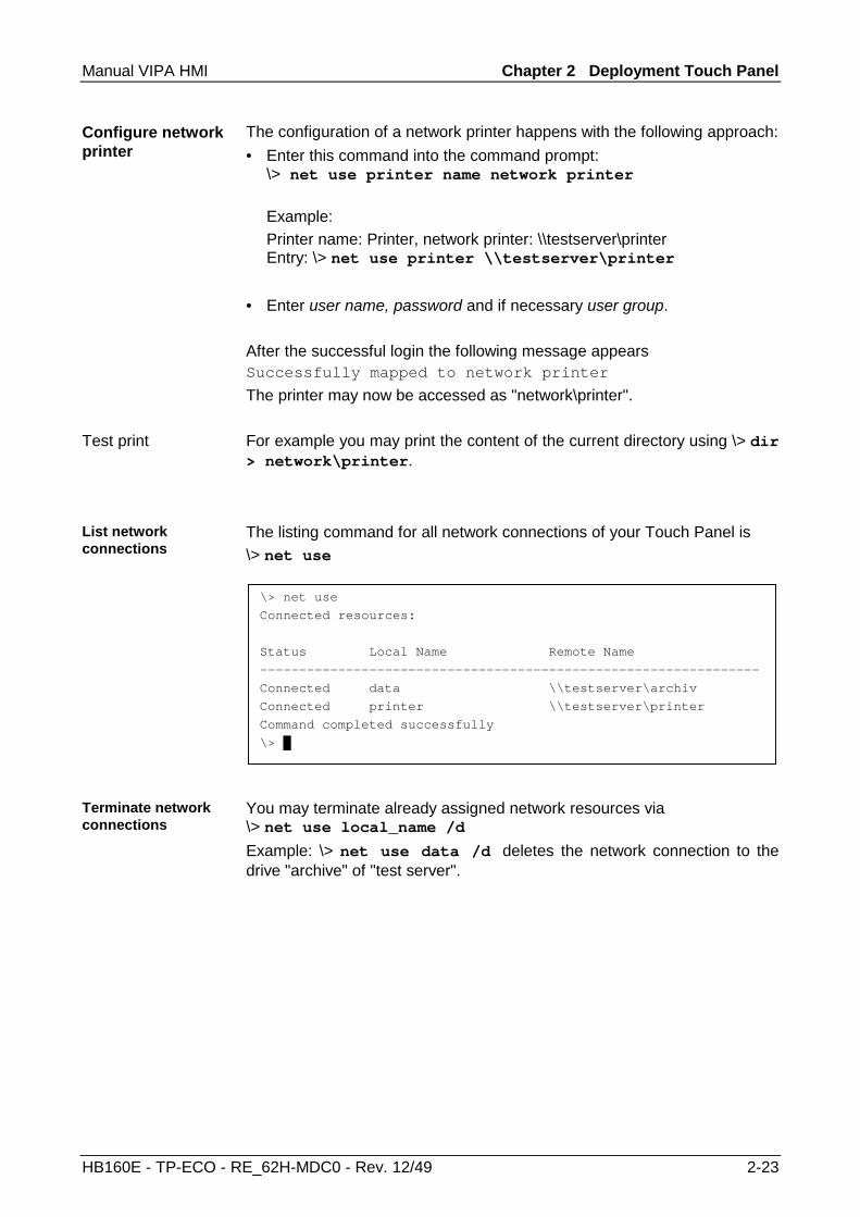
The listing command for all network connections of your Touch Panel is \> net use
You may terminate already assigned network resources via \> net use local_name /d Example: \> net use data /d deletes the network connection to the drive "archive" of "test server".
Configure network printer
Test print
List network connections
Terminate network connections
\> net use
Connected resources:
Status Local Name Remote Name
----------------------------------------------------------------
Connected data \\testserver\archiv
Connected printer \\testserver\printer
Command completed successfully
\> █

Chapter 2 Deployment Touch Panel Manual VIPA HMI
2-24 HB160E - TP-ECO - RE_62H-MDC0 - Rev. 12/49

Manual VIPA HMI Chapter 3 Installation Guidelines
HB160E - TP-ECO - RE_62H-MDC0 - Rev. 12/49 3-1
Chapter 3 Installation Guidelines
The chapter "Installation Guidelines" gives you information about the interference-free installation of Programmable Logic Controls (PLC) together with a Touch Panel. Here we describe possible paths how interference can enter the controller, how you ensure the electromagnetic compatibility (EMC) and how to approach shielding and screening issues.
Topic Page Chapter 3 Installation Guidelines.................................................... 3-1
Basic rules for the EMC-equitable assembly of installations................. 3-2 EMC-equitable assembly...................................................................... 3-6 EMC-equitable cabling ......................................................................... 3-7 Special precautions providing high noise immunity ............................ 3-11 Checklist for the EMC-compliant installation of controllers ................. 3-12
Overview
Content

Chapter 3 Installation Guidelines Manual VIPA HMI
3-2 HB160E - TP-ECO - RE_62H-MDC0 - Rev. 12/49
Basic rules for the EMC-equitable assembly of installations
The term electromagnetic compatibility (EMC) refers to the ability of an electrical device to operate properly in an electromagnetic environment without interference from the environment or without the device causing illegal interference to the environment. The Operation Panels are developed for applications in harsh industrial environments and complies with EMC requirements to a large degree. In spite of this you should implement an EMC strategy before installing any components, which should include any possible source of interference.
Electromagnetic interference can enter your system in many different ways:
Fields
Bus
Power PE
I/O-SignalAutomationSystem
Interference is coupled into your system in different ways, depending in the propagation medium (conducted or not conducted) and the distance to the interference source. We differentiate between: • galvanic coupling • capacitate coupling • inductive coupling • radiated power coupling
What is EMC?
Possible sources for disturbances

Manual VIPA HMI Chapter 3 Installation Guidelines
HB160E - TP-ECO - RE_62H-MDC0 - Rev. 12/49 3-3
The following table shows the four different coupling mechanisms, their causes and possible interference sources.
Coupling mechanism Cause Typical source Galvanic coupling
AutomationSystem
Disruptor
galvaniccoupling line
Galvanic or metallic coupling always occurs, when two current circuits have a common line.
• Pulsed devices (Net influence from transducers and foreign net devices)
• Starting motors • Different potential of
component cubicles with common current supply
• Static discharges
Capacitate coupling
AutomationSystem
Disruptor
capacitivecoupling line
Capacitate or electric coupling occurs between conductors with different potential. The coupling is proportionate to the temporal change of the voltage.
• Interference through parallel signal lines
• Static discharge of the personnel
• Contactors
Inductive coupling
AutomationSystem
Disruptor
inductivecouplinglinewanted signal
Inductive or magnetic coupling occurs between two current active line loops. The magnetic flows associated with the currents induct interference voltages. The coupling is proportional to the time related change of the current.
• Transducers, motors, electric welding devices
• Parallel net cables • Cables with toggled currents• Signal cable with high
frequency • Unused coils
Radiate power coupling
AutomationSystem
Disruptor
radiatedcouplingline
One talks of radiate power coupling, when an electro-magnetic wave meets a line circuit. The hit of the wave inducts currents and voltages.
• Sender in the neighborhood(e.g. walkie-talkie)
• Sparking lines (sparking plugs, collector of electric motors, welding devices)
Coupling mechanisms and interference sources
Chapter 3 Installation Guidelines Manual VIPA HMI
3-4 HB160E - TP-ECO - RE_62H-MDC0 - Rev. 12/49
In many cases, the adherence to some very elementary rules is sufficient to ensure EMC. For this reason we wish to advise you to heed the following rules: During the installation of your automation units you should ensure that any inactive metal components are grounded via a proper large-surface earth! • Interconnect any inactive metal components via low-impedance
conductors with a large cross-sectional area. • Execute screw connections at coated and anodized metal parts either
with special contact washer or remove the isolating protective film. • Install a central connection between the chassis ground and the
earthing/protection system.
Ensure that cabling is routed properly during installation! • Divide the cabling into different cable groups
(High voltage lines, power supply lines, signal lines, data lines). • Always install high voltage lines and signal or data lines in separate
channels or bundles. • Install signal and data lines as close as possible to any metallic ground
surfaces (e.g. frames, metal rails, sheet metal).
Ensure that the screening of lines is grounded properly! • Data lines must be screened. The screen has to be laid both-sided. • Analog lines must be screened. Where low-amplitude signals are
transferred it may be advisable to connect the screen on one side of the cable only.
• Attach the screening of cables to the ground rail by means of large-surface connectors located as close as possible to the point of entry. Fix the cables mechanically by means of cable clamps. Route the connected screen to the modules without interruptions, but don't connect the screen again.
• Ensure that the ground rail has a low-impedance connection to the cabinet/cubicle.
• Use only metallic or metallic covers for the plugs of screened data lines.
Basic rules for ensuring EMC

Manual VIPA HMI Chapter 3 Installation Guidelines
HB160E - TP-ECO - RE_62H-MDC0 - Rev. 12/49 3-5
In critical cases you should implement special EMC measures! • Connect snubber networks to all inductive loads that are not controlled
by special EMC modules. • Use incandescent lamps for illumination purposes inside cabinets or
cubicles, do not use of fluorescent lamps.
Create a single reference potential and ensure that all electrical equipment is grounded wherever possible! • Ensure that grounding measures are implemented effectively. The
controllers are earthend to provide protection and for functional reasons. • Provide a star-shaped connection between the plant, cabinets/cubicles
and the grounding/ protection system. In this way you can avoid ground loops.
• Where potential differences exist, you must install sufficiently large equipotent bonding conductors between the different parts of the plant.

Chapter 3 Installation Guidelines Manual VIPA HMI
3-6 HB160E - TP-ECO - RE_62H-MDC0 - Rev. 12/49
EMC-equitable assembly
Mostly, measures for suppressing interference voltages are only taken, when the control is already in commission and the perfect receive of a wanted signal is disturbed. Causes for such interference's are in the most cases inadequate reference potentials, coming from mistakes at the device assembly and installation.
When assembling the devices, you have to ensure the large-surface grounding of the inactive metal parts. A correctly done grounding supports an unambiguous reference potential for the control and reduces the impact of coupled interferences. Grounding means the conducting connection of all inactive metal parts. The sum of all interconnected inactive parts is called ground. Inactive parts are all conductive parts electrically separated from all active parts by means of a basic isolation and that may only get voltage in case of an error. The ground must not adopt dangerous contact voltage even in case of an error. Thus you have to connect the ground with the protected earth conductor. To avoid ground loops, local distant ground constructions (cubicles, construction and machine parts) have to be connected with the protected earth conductor system in star-topology. Please regard at grounding: • Connect the inactive metal parts as carefully as the active ones. • Take care of impedance-low metal-metal-connections, e.g. with large-
surface and well conductive contacts. • If you include coated or anodized metal parts in the grounding, you have
to come through the isolating protection layers. For this you may use special contact washers or remove the isolation layer.
• Protect the connection points from corrosion, e.g. with grease. • Moveable grounding parts (e.g. cubicle doors) have to be connected via
flexible ground strips. The ground strips should be short and have a large surface, because the surface is decisive for the diversion of high frequency interferences.
Guidelines for assembling and grounding of inactive metal parts

Manual VIPA HMI Chapter 3 Installation Guidelines
HB160E - TP-ECO - RE_62H-MDC0 - Rev. 12/49 3-7
EMC-equitable cabling
Content of this section is the line routing of bus, signal and supply lines. Object of the line routing is to suppress the "slurring" at parallel lines.
For an EMC-equitable routing of the lines it is convenient to divide the cables in different groups and install each group itself:
Group A • screened bus and data lines • screened analog lines • unshielded lines for direct voltage ≤ 60V • unshielded lines for alternating voltage ≤ 25V • Coaxial cables for monitors Group B • unshielded lines for direct voltage >60V and ≤400V • unshielded lines for alternating voltage >25V and ≤400V Group C • unshielded lines for direct and alternating voltage >400V Group D • Lines for H1 respectively TCP/IP
Line routing
Line routing inside and outside of cubicles

Chapter 3 Installation Guidelines Manual VIPA HMI
3-8 HB160E - TP-ECO - RE_62H-MDC0 - Rev. 12/49
Following the table you may see the conditions for the cabling of the line groups by combining the single groups: Group A Group B Group C Group D Group A [1] [2] [3] [4] Group B [2] [1] [3] [4] Group C [3] [3] [1] [4] Group D [4] [4] [4] [1]
[1] The lines may be installed in common bundles or cable trusses.
[2] The lines have to be installed in different bundles or cable trusses (without min. distance).
[3] The lines have to be installed in different bundles or cable trusses inside of cubicles and outside of the cubicle but inside the building in separated cable trusses with a min. distance of 10cm.
[4] The lines have to be installed in different bundles or cable trusses with a min. distance of 50cm.
Wherever possible, exterior cabling should be installed on metallic cable trays. A galvanic connection must be provided for joints between cable trays. You must abide by the applicable lightning protection and grounding regulations when installing exterior cables.
Attention! Where cables and signal lines for PLC equipment are installed outside of buildings, the conditions for internal and external lightning protection must be satisfied. • Exterior lines should either be installed in metallic conduit pipes that is
grounded on both ends or in steel-reinforced concrete cable trunks with continuously connected reinforcing.
• Signal lines should be protected against overvoltage by varistors or by lightning arrester filled with rare gas.
• Install these protective elements at the location where the cables enter the building.
Note! Any lightning protection system must be based on an individual assessment of the entire plant. For questions please contact VIPA GmbH.
Combination of groups
Line routing outside of buildings
Lightning protection

Manual VIPA HMI Chapter 3 Installation Guidelines
HB160E - TP-ECO - RE_62H-MDC0 - Rev. 12/49 3-9
Potential differences can occur between different sections when controllers and peripheral equipment are connected by means of non-isolated connections or the screens of screened cables are connected at both ends and grounded on different sections of the plant. One reason for a potential difference can be that different sections of the plant are powered from different power sources. These potential differences must be reduced by means of equipotential bonding conductors to ensure that the electronic equipment employed on the plant operates properly.
• The lower the impedance of the equipotential bonding conductor, the higher the effectiveness of potential equalization.
• The impedance of the equipotential bonding conductor must not exceed 10% of the impedance of the screen where screened signal lines are connected between the different sections of the plant and the screening is connected to ground/neutral on both sides.
• The cross-sectional area of the equipotential bonding conductor must be calculated to carry the maximum equalization current. The following cross-sections have been successfully employed: - 16mm2 Cu for equipotential bonding conductors up to 200m - 25mm2 Cu for equipotential bonding conductors exceeding 200m.
• Use copper or galvanized steel for equipotential bonding conductors. These must be connected to ground/neutral by means of large-surface connections that are protected from corrosion.
• The equipotential bonding conductor should be installed in such a manner that it includes the smallest surface between the bonding conductor and the signal lines.
Screening is one method commonly used to reduce (attenuate) the interference pick-up from magnetic, electrical or electromagnetic fields. • Interference on screens is conducted to ground by the conductive
connection between the screen and the screening rain/enclosure. To avoid interference from these currents it is very important that the neutral connection is a low-impedance connection.
• You should only use cables that are provided with a braided screen. The degree of screening should be more than 80%.
• Avoid cables with foil-type screens as the foil can be easily damaged by tension and pressure at the point of attachment; this can result in reduced effectiveness of the screening action.
• As a rule you should always ground the screens of cables on both ends. This is the only way in which you can ensure that high frequency interference is attenuated properly.
Equipotential bonding
Rules for equipotential bonding
Screening of lines and cables

Chapter 3 Installation Guidelines Manual VIPA HMI
3-10 HB160E - TP-ECO - RE_62H-MDC0 - Rev. 12/49
In exceptional cases it may be necessary to ground the screen on one side only. However, this will only attenuate the lowest frequencies. The one-sided grounding of screens may provide advantages when: • It is not possible to install an equipotential bonding conductor • Analogue signals (a few mV or µA) must be transmitted • Foil-type screening (static screening) is employed. You should always use metallic or metalized covers for serial data lines. Connect the screen of the data line to the cover. Do not connect the screen to PIN 1 of the connector! In case of stationary operations it is recommended that the remove the insulation from the screened cable without cutting the screen and to attach this point to the screening/neutral rail.
Note! Potential differences can give rise to an equalization current via the screen connected between the two ground connections. In this case you must install an additional equipotential bonding conductor.
Please observe the following points when you handle the screens: • Use only metallic cable clamps when connecting the screening of
cables. These clamps must provide a good electrical contact and a large-surface connection to the screen.
• Attach the screens to the screening rail directly at the point where the cables enter the enclosure. The screening conductor must be continued to the module without interruption, however, it must not be connected to the module!
One-sided grounding of screens
Connecting the screen
Manual VIPA HMI Chapter 3 Installation Guidelines
HB160E - TP-ECO - RE_62H-MDC0 - Rev. 12/49 3-11
Special precautions providing high noise immunity
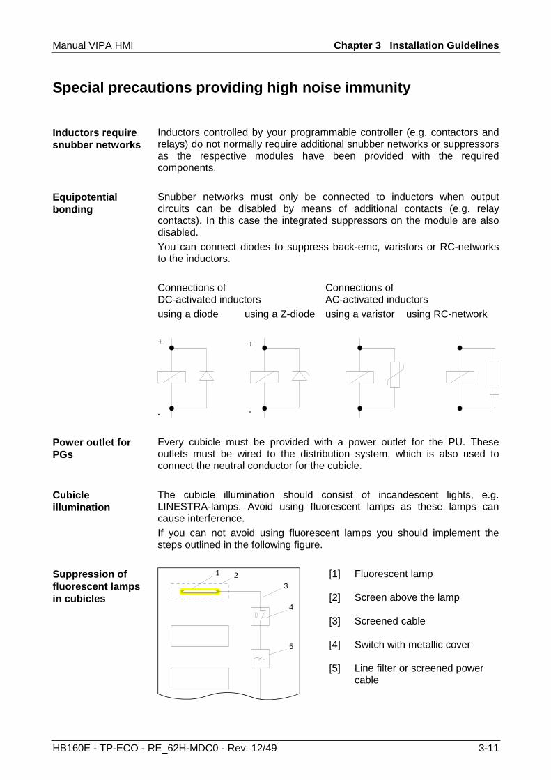
Inductors controlled by your programmable controller (e.g. contactors and relays) do not normally require additional snubber networks or suppressors as the respective modules have been provided with the required components. Snubber networks must only be connected to inductors when output circuits can be disabled by means of additional contacts (e.g. relay contacts). In this case the integrated suppressors on the module are also disabled. You can connect diodes to suppress back-emc, varistors or RC-networks to the inductors. Connections of DC-activated inductors
Connections of AC-activated inductors
using a diode using a Z-diode using a varistor using RC-network
-
+ +
- Every cubicle must be provided with a power outlet for the PU. These outlets must be wired to the distribution system, which is also used to connect the neutral conductor for the cubicle. The cubicle illumination should consist of incandescent lights, e.g. LINESTRA-lamps. Avoid using fluorescent lamps as these lamps can cause interference. If you can not avoid using fluorescent lamps you should implement the steps outlined in the following figure.
[1] Fluorescent lamp
[2] Screen above the lamp
[3] Screened cable
[4] Switch with metallic cover
1
3
4
5
2
[5] Line filter or screened power cable
Inductors require snubber networks
Equipotential bonding
Power outlet for PGs
Cubicle illumination
Suppression of fluorescent lamps in cubicles
Chapter 3 Installation Guidelines Manual VIPA HMI
3-12 HB160E - TP-ECO - RE_62H-MDC0 - Rev. 12/49
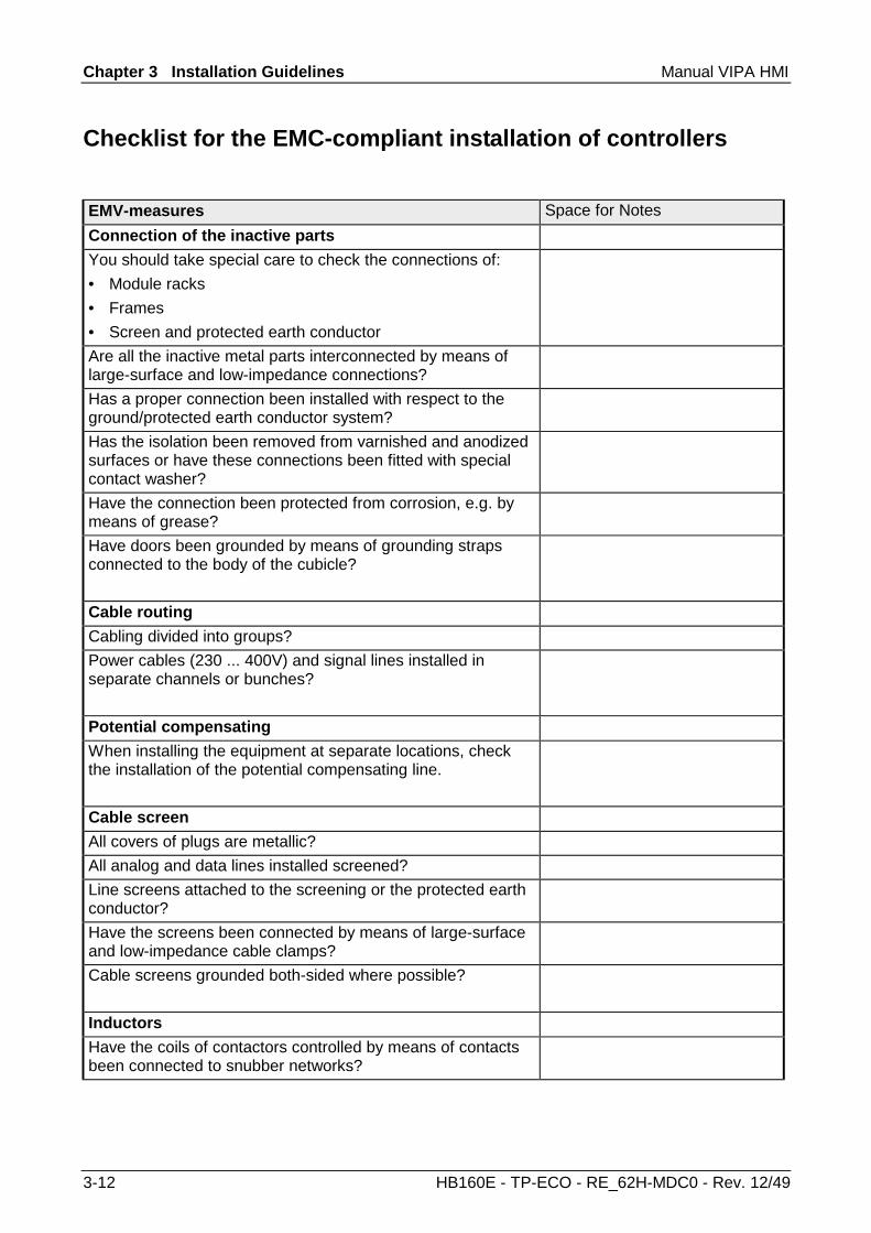
Checklist for the EMC-compliant installation of controllers
EMV-measures Space for Notes Connection of the inactive parts You should take special care to check the connections of: • Module racks • Frames • Screen and protected earth conductor
Are all the inactive metal parts interconnected by means of large-surface and low-impedance connections?
Has a proper connection been installed with respect to the ground/protected earth conductor system?
Has the isolation been removed from varnished and anodized surfaces or have these connections been fitted with special contact washer?
Have the connection been protected from corrosion, e.g. by means of grease?
Have doors been grounded by means of grounding straps connected to the body of the cubicle?
Cable routing Cabling divided into groups? Power cables (230 ... 400V) and signal lines installed in separate channels or bunches?
Potential compensating When installing the equipment at separate locations, check the installation of the potential compensating line.
Cable screen All covers of plugs are metallic? All analog and data lines installed screened? Line screens attached to the screening or the protected earth conductor?
Have the screens been connected by means of large-surface and low-impedance cable clamps?
Cable screens grounded both-sided where possible?
Inductors Have the coils of contactors controlled by means of contacts been connected to snubber networks?