hbl power systems limited
TRANSCRIPT

HBL Power Systems Limited
Hyderabad – TS, India
Electronics Group
Procedure for PCB Assembly
Procedure No.: EG-PP-PR-03, Rev. No.: 0
Details Name Signature Date
Prepared By K Shiva krishna
04/06/2020
Approved By R S Sudhakar
04/06/2020
CONTROL OF CONFIDENTIALITY
The information contained in this document is the property of HBL, which reserves the
right for distribution, application or reproduction for any usage.

Procedure for PCB Assembly
Procedure No. EG-PP-PR-03
Revision No. 0
Page No: 2 of 15
Revision History
Rev.
No
Date of
Revision
Details of
Changes Reason for Change
Rev.No
From To
0 04/06/2020 All Pages Initial Improvement - 0
Distribution List
This Documented Information will be uploaded in QMS Portal for necessary reference.
List of Abbreviations
Sl. No Abbreviation Expansion
1. BOM Bill of Material
2. Dept Department
3. EG Electronics Group
4. FG Finished Goods
5. FT Format
6. PPC Production Planning and Control
7. PP Production and Planning
8. PR Production
9. PMM Permanent Magnet Machines
10. QC Quality Control
11. QMS Quality Management System
12. RE Railway Electronics
13. IE Industrial Electronics
14. STPO Stock Transfer Purchase Order
15. MRN Material Return Note
Procedure for PCB Assembly
Procedure No. EG-PP-PR-03
Revision No. 0
Page No: 3 of 15
Table of Contents
1 Purpose ............................................................................................................................4
2 Scope ...............................................................................................................................4
3 Related Documents ..........................................................................................................4
4 Organization chart ............................................................................................................5
5 Roles, Responsibilities and Authorities ............................................................................6
6 Process flow chart ............................................................................................................7
7 Procedure .......................................................................................................................12
7.1 Sale Order/STPO .....................................................................................................12
7.2 Production Plan ........................................................................................................12
7.3 Production Realization Process ................................................................................12
7.4 Production Process Verification ................................................................................13
7.5 Production Documentation ........................................................................................13
7.6 Control of Production Process Changes ...................................................................13
7.7 Control of Production Equipment ..............................................................................14
7.8 Rejection in Production Process ...............................................................................14
8 Documented Information ................................................................................................15
List of Tables
Table 1: Related Documens ....................................................................................................4
Table 2: Roles, Responsibilities and Authorities .....................................................................6
Table 3: Documented Information .........................................................................................15
List of Figures
Figure 1: Organization Chart ...................................................................................................5
Figure 2: Process Flow Chart ..................................................................................................7

Procedure for PCB Assembly
Procedure No. EG-PP-PR-03
Revision No. 0
Page No: 4 of 15
1 Purpose
This procedure describes the process used to provide controlled conditions under which the
key product realization processes are performed.
2 Scope
This production procedure will cover all activities and process steps (right from the receipt of
material from stores to Dispatch).
3 Related Documents
# Title Document Number Rev No
1 PCB Route Card EG-PP-FT-101 2
2 Stencil Printer EG-PP-FT-102 1
3 Automatic Pick & Place
Machine EG-PP-FT-103 1
4 Reflow Production Report EG-PP-FT-104 1
5 AOI Inspection Report EG-PP-FT-105 0
6 X-Ray Production Report EG-PP-FT-106 0
7 In-Circuit-Test (ICT) Report EG-PP-FT-107 0
8 Manual Assembly Report EG-PP-FT-108 0
9 Wave Soldering Production
Report EG-PP-FT-109 0
10 Post Soldering Work Report EG-PP-FT-110 0
11 Tested Ok Label EG-PP-FT-111 0
12 Preventive Maintenance –
Stencil Printer Machine EG-PP-FT-112 1
13
Preventive Maintenance -
Automatic Pick & Place
Machine
EG-PP-FT-113 1
14 Preventive Maintenance -
Reflow Oven EG-PP-FT-114 1
15 Preventive Maintenance – X-
Ray Machine EG-PP-FT-116 0

Procedure for PCB Assembly
Procedure No. EG-PP-PR-03
Revision No. 0
Page No: 5 of 15
16 Preventive Maintenance –In-
Circuit-Tester EG-PP-FT-117 0
17 Preventive Maintenance –Wave
Soldering Machine EG-PP-FT-118 0
18 Daily Test Report EG-PP-FT-119 1
19 PCB Test Report EG-PP-FT-120 0
20 Factory Sales Register EG-PP-FT-121 0
21 SPI Route Card EG-PP-FT-122 0
22 SPI Power Card PCB Test
Report EG-PP-FT-123 0
23 SPI Control Card PCB Test
Report EG-PP-FT-124 0
24 SPI Display PCB Test Report EG-PP-FT-125 0
25 SPI GSM PCB Test Report EG-PP-FT-126 0
26 SPI In-Process & Final Visual
Inspection Check Sheet EG-PP-FT-127 0
27 SPI System Level Test Report EG-PP-FT-128 0
28 PCB Visual Inspection Report EG-PP-FT-129 0
Table 1: Related Documents
4 Organization chart
Figure 1: Organization Chart

Procedure for PCB Assembly
Procedure No. EG-PP-PR-03
Revision No. 0
Page No: 6 of 15
5 Roles, Responsibilities and Authorities
Production Head
Responsibilities:
1. Ensuring the timely completion of relevant projects.
2. Provide overall Management of the on going Production operations including Troubleshooting, Planning, Scheduling, Documentation, Equipment Maintenance, Non-conformance analysis.
3. Assist in creation of efficient processes through hands-on development and training.
4. Track quality of all processes through analysis of recorded data and formation of additional test-points. Correlate results with requirements / specifications.
5. Identify the training needs to the personnel and coordinate with HRD for organizing the same.
6. Ensure product and personal safety.
7. Ensure configuration management appropriate to the product.
8. Maintaining the respective records
9. Identification of risks and implementation of mitigation plan
Authorities
1. Taking decision in shop-floor to improve productivity.
2. Approving indents.
3. Sanction of leaves
Production
Supervisor
Responsibilities:
1. To coordinate & execute the assigned jobs by meeting the customer requirement as specified, ensure the timely completion.
2. Guide and train the trainees
3. Ensure product and personal safety.
4. Develop innovative ideas to improve production and quality
Authorities:
1. Approving Indent
2. Leave Authorization
Production
Engineer
Responsibilities:
1. To coordinate & execute the assigned jobs by meeting the customer requirement as specified, ensure the timely completion.
2. Guide and train the trainees
3. Ensure product and personal safety.

Procedure for PCB Assembly
Procedure No. EG-PP-PR-03
Revision No. 0
Page No: 7 of 15
Operator
Responsibilities:
1. To execute the assigned jobs by meeting the customer requirement
as specified, ensure the timely completion.
2. Ensure product and personal safety
Table 2: Roles, Responsibilities and Authorities
6 Process flow chart
SMD Components Through hole Components
Blank PCB's
Load the SMD Components on pick and place Machines
Preform the material for Add-on
C
Manually mount the TH components
D
A
B
Kit verification & material
segregation.
Receipt of material from store

Procedure for PCB Assembly
Procedure No. EG-PP-PR-03
Revision No. 0
Page No: 8 of 15
Preheating of PCB Blanks at
110 C for 2 hours
Inspection AOI - Top
side
E
Re-flow Oven
B
Not OK
OK
A
(Stencil Printer) Solder paste printing on
top side of the PCB
Component Placement Top side
OK
Not OK
Visual Inspectio
n
Clean the PCBs with
IPA
Clean the PCBs with
IPA
C
Manually mount the TH components
OK
Rework

Procedure for PCB Assembly
Procedure No. EG-PP-PR-03
Revision No. 0
Page No: 9 of 15
Stencil for Glue application on bottom
side of the PCB
Visual Inspecti
on
Not Ok
OK
Clean the PCBs
with IPA
E
Inspection AOI - Top
side
Rework
C
Re-flow Oven
B
OK
Component Placement Bottom side
OK
Not OK
Clean the PCBs with
IPA
Manually mount the TH components

Procedure for PCB Assembly
Procedure No. EG-PP-PR-01
Revision No. 0
Page No: 10 Of 15
C
Forming of all Thro-hole components
Visual Inspection
Top / Bottom
side
Not OK
OK
First PCB inspection by QC
Wave soldering
Post Soldering works such as Height down, lead cutting , Touch up
F
Manually mount the TH components
Rework
Components insertion

Procedure for PCB Assembly
Procedure No. EG-PP-PR-03
Revision No. 0
Page No: 11 of 15
Rework
OK
Not OK
Functional testing for
PCB’S Final
inspection
Clean the PCBs
with IPA
Not OK
OK
Add-on component Assembly
Rework
D
In process inspectio
n
F
Continue in next page
Cleaning
Testing

Procedure for PCB Assembly
Procedure No. EG-PP-PR-03
Revision No. 0
Page No: 12 of 15
Figure 2: Process Flow Chart
7 Procedure
7.1 Sale Order/STPO
PPC will released the sale order/STPO from customer.
7.2 Production Plan
PPC will circulate the production plan based on the customer requirement.
7.3 Production Realization Process
Production Realization Process involves the activities for Rail Electronics (RE), Permanent
magnet machines (PMM) and Industrial Electronics(IE) as Processes are performed under
controlled conditions and include the following:
Conformal Coating
PCB’s Serial number Sticker
Final QC Sample test
Rework
Not OK
OK
Packing in Anti Static Covers
Handed over to stores

Procedure for PCB Assembly
Procedure No. EG-PP-PR-03
Revision No. 0
Page No: 13 of 15
7.4 Production Process Verification
Use a representative item from the first production run to verify that the process and tooling
are capable of producing conforming product.
Planned work instructions such as Work Instructions, Route Cards are to ensure product
requirements/characteristics are identified, verified, and documented.
7.4.1 Engineering Department approves all processes and equipment by approving all
process and equipment quality plans, procedures, or work instructions.
7.4.2 Route Cards and Quality Records provide evidence that all manufacturing, test, and
inspection operations have been completed as planned.
7.4.3 Prevention, detection, and removal of loose foreign objects is performed according to
work instructions and Inspection instructions as applicable prior to final product
acceptance.
7.4.4 Utilities and supplies are monitored to assure they meet process, environmental, and
product quality requirements.
7.4.5 Criteria for workmanship, expressed as product specifications/characteristics are
documented in the quality plan for the product.
7.5 Production Documentation
7.5.1 Production documentation consists of documentation packages which include:
7.5.2 Route Cards, process flow charts that define the sequence of operations required to
assemble, test, inspect, and accept product
7.5.3 Specific or non-specific tools and numerical control machine programs required, along
with instructions for use.
7.6 Control of Production Process Changes
7.6.1 Identified changes communicate to engineering team through engineering change
request.
7.6.2 Engineering reviews and approves all changes to production processes and gives
engineering change note to production.
7.6.3 Production Process changes are verified following implementation by inspection and/or
test to assure changes have been implemented and the changes meet the desired
effect, without adverse effect on product quality.
Procedure for PCB Assembly
Procedure No. EG-PP-PR-03
Revision No. 0
Page No: 14 of 15
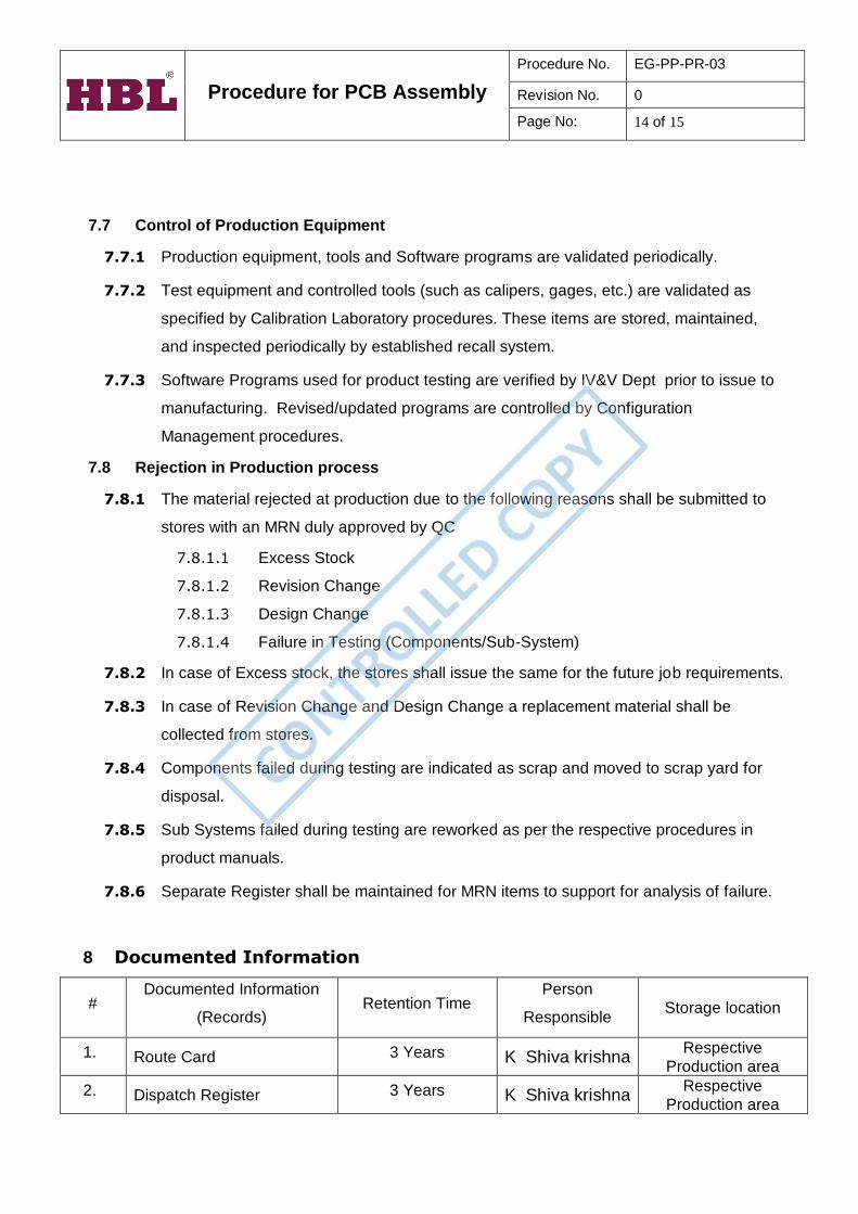
7.7 Control of Production Equipment
7.7.1 Production equipment, tools and Software programs are validated periodically.
7.7.2 Test equipment and controlled tools (such as calipers, gages, etc.) are validated as
specified by Calibration Laboratory procedures. These items are stored, maintained,
and inspected periodically by established recall system.
7.7.3 Software Programs used for product testing are verified by IV&V Dept prior to issue to
manufacturing. Revised/updated programs are controlled by Configuration
Management procedures.
7.8 Rejection in Production process
7.8.1 The material rejected at production due to the following reasons shall be submitted to
stores with an MRN duly approved by QC
7.8.1.1 Excess Stock
7.8.1.2 Revision Change
7.8.1.3 Design Change
7.8.1.4 Failure in Testing (Components/Sub-System)
7.8.2 In case of Excess stock, the stores shall issue the same for the future job requirements.
7.8.3 In case of Revision Change and Design Change a replacement material shall be
collected from stores.
7.8.4 Components failed during testing are indicated as scrap and moved to scrap yard for
disposal.
7.8.5 Sub Systems failed during testing are reworked as per the respective procedures in
product manuals.
7.8.6 Separate Register shall be maintained for MRN items to support for analysis of failure.
8 Documented Information
# Documented Information
(Records) Retention Time
Person
Responsible Storage location
1. Route Card 3 Years K Shiva krishna Respective
Production area
2. Dispatch Register 3 Years K Shiva krishna Respective
Production area

Procedure for PCB Assembly
Procedure No. EG-PP-PR-03
Revision No. 0
Page No: 15 of 15
Table 3: Documented Information