hbs-ap assembling instructions - teseo assembling instructions 1. introduction ... ry to know their...
TRANSCRIPT

UM PIPEWORK - ALUMINIUM PIPEWORK - ALUMINIUM PIPEWORK - ALUMINIUM PIPEWORK
STRIBUTION SYSTEMS - FLUID POWER DISTRIBUTION SYSTEMS - FLUID POWER DISTRIBUTION SYSTEM
HBS-AP ASSEMBLING INSTRUCTIONS
1. INTRODUCTION
1.1. This manual is very easy to consult and we recommend reading it before starting work, bearing in mind the re-gulations in your country.
1.2. Pay attention to the instructions identified by the mark ATTENTION.
1.3. The HBS and AP ranges of products from TESEO are suitable for the distribution of compressed air, nitrogen, vacuum and inert gases.
1.4. For any application with water distribution, please check our sheet on page 92. For other fluids it is necessa-ry to know their exact composition and to check if they are compatible with the HBS and AP system; in case of any doubt, please contact the technical department of TESEO.
1.5. ATTENTION: TESEO is not responsible for problems due to failure to follow the instructions contai-ned in within this manual.
3. PREPARATION
3.1. Cutting: this can be done by hand, using a hacksaw provided that the blade has been lubricated with vaseline or other oils, as aluminium is a material which could clog the tool. When making many cuts, we suggest using a circular chop saw with metal cutting blade.
3.2. Deburring: after cutting the pipe, it is necessary to remove the sharp edges using a de-burring tool. This operation is required to avoid any damage to the o-ring and to make easier the connection.
2. TOOLS AND FIXTURES
2.1. The tools required to install even a small system are: one Allen wrench for 4 and 5 mm slots, one de-burring tool or one scraper, neutral grease, one drill bit and one drilling machine, one hacksaw, some small tubes for placing the small plates, one tape measure.
2.2. The tools suggested for fast and safe work are: one pair of adjustable pliers, one battery screwdriver, one drilling jig, one chop saw with metal circular blade, one stepped cone cutter or cone cutter, one PTFE tape or sealing band, one torque wrench, one level or one plumb line, one bench on wheels.
2.3. Close attention should be paid to safety. To this purpose, scaffolding, helmets, harnesses, gloves and protec-tive glasses must be used by all personnel.
2.4. ATTENTION: follow the regulations concerning safety at work presently in force in your country.

ALUMINIUM PIPEWORK - ALUMINIUM PIPEWORK - ALUMINIUM PIPEWORK - ALUMIN
LUID POWER DISTRIBUTION SYSTEMS - FLUID POWER DISTRIBUTION SYSTEMS - FLUID POWER DISTRI
3.3. Lubrication: in order to make it easier to insert joint, lubrica-te the inner surface of the hollow bar, in order to avoid any da-mage to the O ring.
3.5. Hole de-burring: on outlet plates we recommend de-burring a maximum 1mm around the hole in order not to damage the o ring seal.
3.6. ATTENTION: Wear protective glasses and gloves during cutting and drilling. Flying chips could cause injury to eyes and hands.
The following tools can be used: a drill, a coned drill, a counter bore, a hole saw.
The maximum diameter of the smoothed hole must not exceed the recommended diameter. Please see the table.
3.4. Drilling: during the drilling operation, it is required to have the pilot hole in the centre of the pipe. Please use a drilling jig.
4. HBS SYSTEM ASSEMBLY OPERATIONS
4.1. Insertion of small plates: the small plates can be inserted into the slot in the bar at any point. Straighten and secure them by means of sharpened small tubes.
4.2. Joint insertion: to make it easier, first insert the plates and the small plates with loose screws into the slots, then insert the joint and connect the second bar. Now position the plates half-way on each side and tighten the screws.
4.3. How to tighten the screws: The screws must be tightened but be careful not to tear the thread. The torque of the m6 screws should be between a minimum of 10 N·m (91 inch-lbs) and a maximum of 13.5 N·m (120 inch-lbs).
4.4. “L” and “T” Joint have to be fixed using specific fixing plates. They allow you to fix pipes on two sides. Should you need to connect HBS 25 piping, using an “L” joint on the narrow side, it is required to cut 6 mm on each corner.
4.5. Expansion of the line: for lines with a straight section longer than 50 meters, we suggest mounting a sliding joint every 30 to 40 meters. This will make any fu-ture dismantling easier. The two fixing plates have to be assembled in the middle of the available space.
4.6. ATTENTION: check that all the screws are tightened at the end of each pipe connection and when securing them be careful not to tear the thre-ad.
HBS
AP

UM PIPEWORK - ALUMINIUM PIPEWORK - ALUMINIUM PIPEWORK - ALUMINIUM PIPEWORK
STRIBUTION SYSTEMS - FLUID POWER DISTRIBUTION SYSTEMS - FLUID POWER DISTRIBUTION SYSTEM
6.3. Isolation valves: ball valves must be mounted both at the beginning of the line and at the beginning of the branches of the main line. Mount a pressure gauge at the beginning of the main line and a safety valve on the air receiver.
6.4. Take-offs: for the down tubes: to prevent any impurities fouling the bottom of the hollow bar, we recommend fitting the outlet plates on the sides of the hollow bar.
6.5. Flexible pipe: its use is recommended in order to isolate the installation from the vibrations of the compressor.
6.6. Earthing: it is recommended in case of stray electrical currents.
6.7. ATTENTION: wear a safety helmet, harnesses and use scaffolding in com-pliance with the law before tracing and installing the line, as these opera-tions are usually carried out at a dangerous height.
5. AP SYSTEM ASSEMBLY OPERATIONS
5.1. Clamping brackets installation: insert one side of the clamping bracket in the groove of the profile, push both clamping brackets to touch the profiles and tighten the screws.
5.2. Joints: introduce the joint into one pipe, then connect the second pipe, position the clamping bracket equally so that it is clamping both pipes or fitting and half the other and finally tighten the screws.
5.3. Screws tightening: Screws must be tightened properly but not excessively, to avoid stripping the threads. The recommended tightening torque for M5 screws is beetween 9 N·m and 11 N·m maximum. For M6 screws the minimum is 13 N·m and the maximum 15 N·m.
5.4. ATTENTION: once completed the assembly of every joint, double check the screws correct blockage and be sure that no threads are damaged for excessive tightening.
6. INSTALLATION
6.1. How to trace the distribution line: trace a horizontal line at the chosen height by means of a stretched plumb line. With the TESEO system you do not need to give the inclination to collect the condensate as the up-column and the down-column are already equipped at the bottom with a collection and a drain valve.
6.2. How to secure the pipework: The pipework can be supported by several types of ceiling or wall mounted fi-xing plates and brackets. The recommended distance between these fixing brackets is 2 to 4 meters, depen-ding on the weight of the distributed fluid.
ALUMINIUM PIPEWORK - ALUMINIUM PIPEWORK - ALUMINIUM PIPEWORK - ALUMIN
LUID POWER DISTRIBUTION SYSTEMS - FLUID POWER DISTRIBUTION SYSTEMS - FLUID POWER DISTRI
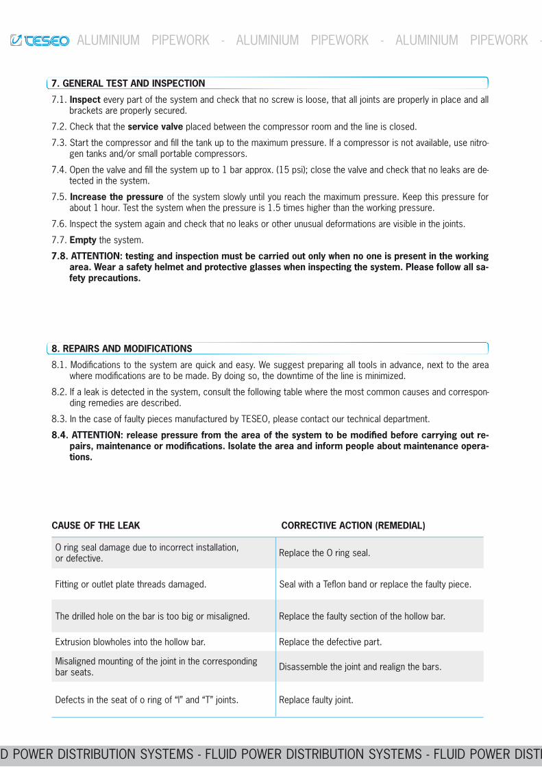
O ring seal damage due to incorrect installation, or defective. Replace the O ring seal.
Fitting or outlet plate threads damaged. Seal with a Teflon band or replace the faulty piece.
The drilled hole on the bar is too big or misaligned. Replace the faulty section of the hollow bar.
Extrusion blowholes into the hollow bar. Replace the defective part.
Misaligned mounting of the joint in the corresponding bar seats. Disassemble the joint and realign the bars.
Defects in the seat of o ring of “l” and “T” joints. Replace faulty joint.
CAUSE OF THE LEAK CORRECTIVE ACTION (REMEDIAL)
8. REPAIRS AND MODIFICATIONS
8.1. Modifications to the system are quick and easy. We suggest preparing all tools in advance, next to the area where modifications are to be made. By doing so, the downtime of the line is minimized.
8.2. If a leak is detected in the system, consult the following table where the most common causes and correspon-ding remedies are described.
8.3. In the case of faulty pieces manufactured by TESEO, please contact our technical department.
--
tions.
7. GENERAL TEST AND INSPECTION
7.1. Inspect every part of the system and check that no screw is loose, that all joints are properly in place and all brackets are properly secured.
7.2. Check that the service valve placed between the compressor room and the line is closed.
7.3. Start the compressor and fill the tank up to the maximum pressure. If a compressor is not available, use nitro-gen tanks and/or small portable compressors.
7.4. Open the valve and fill the system up to 1 bar approx. (15 psi); close the valve and check that no leaks are de-tected in the system.
7.5. Increase the pressure of the system slowly until you reach the maximum pressure. Keep this pressure for about 1 hour. Test the system when the pressure is 1.5 times higher than the working pressure.
7.6. Inspect the system again and check that no leaks or other unusual deformations are visible in the joints.
7.7. Empty the system.
7.8. ATTENTION: testing and inspection must be carried out only when no one is present in the working area. Wear a safety helmet and protective glasses when inspecting the system. Please follow all sa-fety precautions.