hd radio™ air interface design description layer 2 channel ... · 5.1.1 mps and sps multiplexing...
TRANSCRIPT

HD Radio™ Air Interface Design Description
Layer 2 Channel Multiplex Rev. I
August 23, 2011
SY_IDD_1014s

TRADEMARKS HD Radio™ and the HD, HD Radio, and “Arc” logos are proprietary trademarks of iBiquity Digital Corporation.
“iBiquity”, "iBiquity Digital", and the iBiquity Digital logo are also proprietary trademarks of iBiquity.
All other trademarks, whether claimed or registered, are the exclusive property of their respective owners.
iBiquity Digital Corporation 6711 Columbia Gateway Drive, Suite 500 Columbia, MD 21046 Voice: 443-539-4290 Fax: 443-539-4291 E-mail address: [email protected]
Doc. No.: SY_IDD_1014s

HD Radio™ Air Interface Design Description – Layer 2 Channel Multiplex
Table of Contents
Contents 1 SCOPE ..............................................................................................................................................................1
1.1 System Overview.......................................................................................................................................1 1.2 Document Overview..................................................................................................................................1
2 REFERENCE DOCUMENTS ...........................................................................................................................2 3 ABBREVIATIONS AND CONVENTIONS.......................................................................................................3
3.1 Introduction ...............................................................................................................................................3 3.2 Abbreviations and Acronyms ....................................................................................................................3 3.3 Presentation Conventions ..........................................................................................................................4 3.4 Mathematical Symbols ..............................................................................................................................4 3.4.1 Variable Naming Conventions ..............................................................................................................4 3.4.2 Arithmetic Operators.............................................................................................................................5
4 LAYER 2 TRANSPORT – DESCRIPTION......................................................................................................6 5 LAYER 2 PDU GENERATION.........................................................................................................................8
5.1 Layer 2 PDU Structure and Content ..........................................................................................................8 5.1.1 MPS and SPS Multiplexing.................................................................................................................10 5.2 Layer 2 PCI..............................................................................................................................................13 5.3 Order of Content......................................................................................................................................15
6 LAYER 2 PROCESSING................................................................................................................................17 6.1 Transmit Processing Description.............................................................................................................17
Doc. No.: SY_IDD_1014s i 23.AUGUST.2011 – Rev.: I

HD Radio™ Air Interface Design Description – Layer 2 Channel Multiplex
List of Figures Figure 4-1: Layer 2 – Interface Diagram.......................................................................................................................7 Figure 5-1: L2 PDU Structure Based on Content ..........................................................................................................9 Figure 5-2: Generic L2 Transfer Frame.......................................................................................................................13 Figure 5-3: Order of Content .......................................................................................................................................15 Figure 5-4: Layer 2 Order of Multiple Instances of Audio-Oriented Content .............................................................15 Figure 5-5: Layer 2 Order of Data Content Control Information ................................................................................16
List of Tables Table 5-1: Mapping of Services/Programs to Logical Channels vs FM Service Mode – Example Configurations ....10 Table 5-2: Mapping of Services/Programs to Logical Channels vs AM Service Mode – Example Configurations ...12 Table 5-3: Generic Header Sequence Indications........................................................................................................13 Table 5-4: Header Spread Parameters .........................................................................................................................14
Doc. No.: SY_IDD_1014s ii 23.AUGUST.2011 – Rev.: I

HD Radio™ Air Interface Design Description – Layer 2 Channel Multiplex
1 Scope
1.1 System Overview
The iBiquity Digital Corporation HD Radio™ system is designed to permit a smooth evolution from current analog amplitude modulation (AM) and frequency modulation (FM) radio to a fully digital in-band on-channel (IBOC) system. This system delivers digital audio and data services to mobile, portable, and fixed receivers from terrestrial transmitters in the existing medium frequency (MF) and very high frequency (VHF) radio bands. Broadcasters may continue to transmit analog AM and FM simultaneously with the new, higher-quality, and more robust digital signals, allowing themselves and their listeners to convert from analog to digital radio while maintaining their current frequency allocations.
1.2 Document Overview
This document defines Layer 2, the channel multiplexer. Specific hardware and software implementation is not described. See References [1], [2], [7], [9], [4], [5], and [6] for more details.
Doc. No.: SY_IDD_1014s 1 23.AUGUST.2011 – Rev.: I

HD Radio™ Air Interface Design Description – Layer 2 Channel Multiplex
2 Reference Documents
STATEMENT Each referenced document that is mentioned in this document shall be listed in the following iBiquity document:
● Reference Documents for the NRSC In-Band/On-Channel Digital Radio Broadcasting Standard Document Number: SY_REF_2690s
Doc. No.: SY_IDD_1014s 2 23.AUGUST.2011 – Rev.: I

HD Radio™ Air Interface Design Description – Layer 2 Channel Multiplex
3 Abbreviations and Conventions
3.1 Introduction
Section 3 provides the following:
● Abbreviations and Acronyms
● Presentation Conventions
● Mathematical Symbols
3.2 Abbreviations and Acronyms
AAS Advanced Application Services AAT AAS Data Transport AM Amplitude Modulation CA Conditional Access CW Control Word DDL Data Delimiter FM Frequency Modulation HD RLS HD Radio Link Subsystem IBOC In-Band On-Channel ISO International Organization for Standardization L1 Layer 1 L2 Layer 2 MF Medium Frequency MPS Main Program Service MPSA Main Program Service Audio MPSD Main Program Service Data MSB Most Significant Bit PCI Protocol Control Information PDU Protocol Data Unit PIDS Primary IBOC Data Service Logical Channel PSD Program Service Data SIDS Secondary IBOC Data Service Logical Channel SIS Station Information Service SPS Supplemental Program Service SPSA Supplemental Program Service Audio SPSD Supplemental Program Service Data VHF Very High Frequency
Doc. No.: SY_IDD_1014s 3 23.AUGUST.2011 – Rev.: I

HD Radio™ Air Interface Design Description – Layer 2 Channel Multiplex
3.3 Presentation Conventions
Unless otherwise noted, the following conventions apply to this document:
● All vectors are indexed starting with 0.
● The element of a vector with the lowest index is considered to be first.
● In drawings and tables, the leftmost bit is considered to occur first in time.
● Bit 0 of a byte or word is considered the least significant bit.
● When presenting the dimensions of a matrix, the number of rows is given first (e.g., an n x m matrix has n rows and m columns).
● In timing diagrams, earliest time is on the left.
● Binary numbers are presented with the most significant bit having the highest index.
● In representations of binary numbers, the least significant bit is on the right.
3.4 Mathematical Symbols
3.4.1 Variable Naming Conventions The variable naming conventions defined below are used throughout this document.
Category Definition Examples
Lower and upper case letters Indicates scalar quantities i, j, J, g11
Underlined lower and upper case letters Indicates vectors u, V
Double underlined lower and upper case letters Indicates two-dimensional matrices u, V
[i] Indicates the ith element of a vector, where i is a non-negative integer u[0], V[1]
[ ] Indicates the component of a vector v = [0, 10, 6, 4]
[i] [j]
Indicates the element of a two-dimensional matrix in the ith row and jth column, where i and j are non-negative integers
u[i][j], V[i][j]
⎥⎦
⎤⎢⎣
⎡ Indicates the components of a matrix ⎥⎦
⎤⎢⎣
⎡=
572130
m
n … m Indicates all the integers from n to m, inclusive 3 … 6 = 3, 4, 5, 6
n:m Indicates bit positions n through m of a binary sequence or vector
Given a binary vector i = [0, 1, 1, 0, 1, 1, 0, 0], i2:5 = [1, 0, 1, 1]
Doc. No.: SY_IDD_1014s 4 23.AUGUST.2011 – Rev.: I

HD Radio™ Air Interface Design Description – Layer 2 Channel Multiplex
3.4.2 Arithmetic Operators The arithmethic operators defined below are used throughout this document.
Category Definition Examples · Indicates a multiplication operation 3·4 = 12
INT( ) Indicates the integer portion of a real number INT(5/3) = 1 INT(-1.8) = -1
a MOD b Indicates a modulo operation 33 MOD 16 = 1
⊕ Indicates modulo-2 binary addition 011 =⊕
| Indicates the concatenation of two vectors
A = [ B | C ] The resulting vector A consists of the elements of B followed by the elements of C.
j Indicates the square-root of -1 j = 1−
Re( ) Indicates the real component of a complex quantity If x = (3 + j4), Re(x) = 3
Im( ) Indicates the imaginary component of a complex quantity If x = (3 + j4), Im(x) = 4
log10 Indicates the base-10 logarithm log10(100) = 2
* Indicates complex conjugate If x = (3 + j4), x* = (3 - j4)
0x Indicates a hexadecimal value 0x10 = 16
Doc. No.: SY_IDD_1014s 5 23.AUGUST.2011 – Rev.: I

HD Radio™ Air Interface Design Description – Layer 2 Channel Multiplex
4 Layer 2 Transport – Description
The primary function of Layer 2 is to receive audio and data from various higher layers within the HD Radio system, multiplex this information into Layer 2 Protocol Data Units (PDU) and route these PDUs to the appropriate Layer 1 logical channel. The data received from the higher layers is also in the form of PDUs but from the individual transport layers providing the service. Layer 2 enables the HD Radio system to support four transport services as described below and shown in Figure 4-1:
1. Main Program Service (MPS) which includes Main Program Service Audio (MPSA) and may also include Main Program Service Data (MPSD). MPS PDUs are generated by the Audio Transport and encapsulate both MPSA and MPSD information.
2. Supplemental Program Service (SPS) provides the broadcaster the option of multiplexing additional programs with the MPS. The SPS includes Supplemental Program Service Audio (SPSA) and may also include Supplemental Program Service Data (SPSD). SPS PDUs are generated by the same Audio Transport as the MPS PDUs.
3. Advanced Application Services (AAS) provides the broadcaster the option of multiplexing additional types of content, other than SPS, along with the MPS. It provides the packet transport mechanism for these services. It performs the framing and the encapsulation of the data packets. There are two types of methods for multiplexing AAS data into a Layer 2 PDU: fixed and opportunistic. Fixed data is granted a fixed bandwidth allocation by purposely scaling back the bandwidth allocation of the MPS, whereas opportunistic makes use of any unused bandwidth due to variability of both the MPS and SPS Audio.
4. Station Information Service (SIS) is a specialized transport/data link for transmitting SIS data on the Primary IBOC Data Service (PIDS) and the Secondary IBOC Data Service (SIDS) Layer 1 logical channels. For such Layer 1 logical channel, Layer 2 does not perform a multiplexing function, but rather just passes the SIS (PDUs) directly into the Layer 1 PIDS or SIDS logical channel without additional overhead in the form of headers. The SIS PDU is the only PDU contained within the PIDS or SIDS Layer 1 logical channel.
The HD Radio system supports various configurations with respect to Layer 1. Based on the Layer 1 service mode, the system provides multiple Layer 1 logical channels. The number of active Layer 1 logical channels and the characteristics defining them vary for each service mode. The defining characteristics of each Layer 1 logical channel are:
● Transfer Frame Size
● Transfer Frame Rate
● Robustness
● Latency
Details of the logical channels used for each L1 service mode are described in References [1] and [2].
With respect to the exchange between Layer 2 and Layer 1, Layer 2 is subjected to the Layer 1 configuration and timing. The configuration is governed by the control information received from the Configuration Administrator. The total Layer 1 frame size consists of the total Layer 2 PDU size and the L2 Protocol Control Information (PCI) overhead. Layer 2 allows the MPS/SPS and AAS Transports to be active within any active Layer 1 logical channel, with the exception of PIDS and SIDS.
Doc. No.: SY_IDD_1014s 6 23.AUGUST.2011 – Rev.: I

HD Radio™ Air Interface Design Description – Layer 2 Channel Multiplex
SIS
PD
Us
from
the
SIS
Tra
nspo
rt
Str
eam
s of
MP
S P
DU
sfr
om th
eA
udio
Tra
nspo
rt
L2 P
DU
s
Layer 2 (Channel Multiplex)
P1
P2
P3
PID
S
S1
S2
S3
S4
S5
SID
S
L2 PDUs to Layer 1 (Waveform / Transmission)
AA
S P
DU
sfr
om th
eA
AT
Str
eam
s of
SP
S P
DU
sfr
om th
eA
udio
Tra
nspo
rt
P4
All Digital Only{ Upper Layer Definitions are TBD }
Figure 4-1: Layer 2 – Interface Diagram
In addition to the Layer 2 PDUs, status information is also passed between Layer 1 and Layer 2. The status information passed from Layer 1 to Layer 2 consists of Absolute L1 Frame Number (ALFN) and L1 Block Count (BC).
Doc. No.: SY_IDD_1014s 7 23.AUGUST.2011 – Rev.: I

HD Radio™ Air Interface Design Description – Layer 2 Channel Multiplex
5 Layer 2 PDU Generation
This section describes the Layer 2 Protocol Control Information (PCI) included as part of the Layer 2 PDU for every Layer 1 logical channel in the HD Radio system. It also describes the details of how the various service PDUs are multiplexed into a Layer 2 PDU.
5.1 Layer 2 PDU Structure and Content
SPS and AAS are optional. But when available, the structure of a Layer 2 PDU can contain five different possible combinations of audio and data:
a. The payload is audio oriented (MPS/SPS). b. A mixed content payload, containing MPS/SPS, opportunistic data. c. A mixed content payload, containing MPS/SPS, fixed data. d. A mixed content payload, containing MPS/SPS, opportunistic data and fixed data. e. The payload contains fixed data.
Figure 5-1 shows the structure of an L2 PDU depending on content. This does not apply to the PIDS or SIDS logical channels which exclusively carry SIS PDUs. It represents the L2 PDU structures for each logical channel carrying combinations of audio and data.
Opportunistic data is made available only when the audio (MPS/SPS) does not use its allocated bandwidth. The MPS/SPS PDU lengths are based on the maximum bit rate for a particular audio codec mode. The unused portions of the bandwidth are then aggregated and used to include opportunistic data. It can originate in both the MPS and SPS; however, it is combined in the AAS Data Transport using the HD RLS before sending it to Layer 2 as part of the AAS PDUs.
Thus, opportunistic data is PDU-specific and cannot be guaranteed at any particular rate or instance in time, making it a service of lesser quality. Also, fixed data and opportunistic data can occur independently across logical channels.
When the L2 PDU contains an AAS Data PDU containing fixed data, an extended header is deployed within the HD RLS. The format and structure of both fixed and opportunistic data processed by the HD RLS is described in [5]. The mixed content PDU requires additional indications. A delimiter is provided by HD RLS, indicating the payload parts associated with each type of service. To allow opportunistic data to be identified in the Layer 2 PDU, a 5-byte data delimiter (DDL) field is used to identify the start of the opportunistic data in the PDU. Refer to [5] for details.
Doc. No.: SY_IDD_1014s 8 23.AUGUST.2011 – Rev.: I

HD Radio™ Air Interface Design Description – Layer 2 Channel Multiplex
Firs
t B
it
Last
B
it
MPS / SPS only
MPS / SPSand Opportunistic data
MPS / SPSandFixed data
MPS / SPSOpportunistic dataFixed data
Fixed data only
MPSA / MPSD / SPSA / SPSD
MPSA / MPSD / SPSA / SPSD Opportunistic data
MPSA / MPSD / SPSA / SPSD Fixed data
MPSA / MPSD / SPSA / SPSD Opportunistic data Fixed data
Fixed data
Figure 5-1: L2 PDU Structure Based on Content
Doc. No.: SY_IDD_1014s 9 23.AUGUST.2011 – Rev.: I

HD Radio™ Air Interface Design Description – Layer 2 Channel Multiplex
5.1.1 MPS and SPS Multiplexing
MPS and SPS employ an identical transport mechanism; thus, care must be taken when multiplexing these PDUs into a Layer 2 PDU so that the receiver can correctly process the PDUs as well as provide the listener with an accurate description of the available programs. This requires further attention due to the fact that both MPSA and SPSA can contain core and enhanced streams that are transported on different Layer 1 logical channels. This subsection describes the restrictions and configurations when multiplexing and processing MPS and SPS programs.
Table 5-1 shows various configurations for mapping services/programs to logical channels for each FM service mode. The desired broadcast configuration is chosen based on the quality of service for the particular application, in combination with allocation requirements as described in this document. Table 5-1 is a set of sample configurations based on a maximum of three SPSs in addition to the MPS; however, additional configurations can be added in the future to include up to seven SPSs.
Layer 2 PDU construction adheres to the following guidelines:
The Main Program Service is always designated as Program Number “0”.
SPS1 and SPS2 can reference Program Numbers 1 through 7. Refer to [4] for a detailed description on Program Number and program indications.
AAS Data consists of fixed data and the opportunistic data, if available.
Programs 1 through 7 can be added or removed at any time, but Program 0 is constantly present.
The core stream is added or removed first in a multi-stream program.
The Main Program must be first in the order in the physical L2 PDU.
Free-access Supplemental Programs can be placed in any order in the PDU.
Conditionally-accessed Supplemental Programs shall be placed last in the PDU. Refer to Subsection 5.3 for details.
Table 5-1: Mapping of Services/Programs to Logical Channels vs FM Service Mode – Example Configurations
MPS SPS-1 SPS-2 SPS-3
Serv
ice
Mod
e
Cor
e C
hann
el
Enha
nced
C
hann
el
Cor
e C
hann
el
Enha
nced
C
hann
el
Cor
e C
hann
el
Enha
nced
C
hann
el
Cor
e C
hann
el
Enha
nced
C
hann
el
SIS Data
AAS Data (Fixed Data and Opportunistic Data)
P1 — — — — — — — PIDS P1 P1 — P1 — — — — — PIDS P1 MP1 P1 — P1 — P1 — — PIDS P1 P1 — P3 — — — — — PIDS P1/P3
MP2 P1 — P1 — P3 — — PIDS P1/P3 P1 — P3 — — — — — PIDS P1/P3 P1 — P1 — P3 — — — PIDS P1/P3 P1 — P1 P3 — — — — PIDS P1/P3 P1 — P3 P1 — — — — PIDS P1/P3 P1 — P1 — P1 P3 — — PIDS P1/P3
MP3
P1 — P1 — P3 P1 — — PIDS P1/P3
Doc. No.: SY_IDD_1014s 10 23.AUGUST.2011 – Rev.: I

HD Radio™ Air Interface Design Description – Layer 2 Channel Multiplex
MPS SPS-1 SPS-2 SPS-3
Serv
ice
Mod
e AAS Data
Cor
e C
hann
el
Enha
nced
C
hann
el
Cor
e C
hann
el
Enha
nced
C
hann
el
Cor
e C
hann
el
Enha
nced
C
hann
el
Cor
e
Enha
nced
(Fixed Data and
Cha
nnel
Cha
nnel
SIS Data Opportunistic Data)
P1 — P1 — P3 P4 — — PIDS P1/P3/P4 P1 — P1 — P1 — P3 P4 PIDS P1/P3/P4 MP11 P1 — P1 — P3 — P4 — PIDS P1/P3/P4 P1 P2 — — — — — PIDS P1/P2/P3 P1 P2 P2 — — — — — PIDS P1/P2/P3 P1 P2 P2 — P3 — — — PIDS P1/P2/P3 P1 P2 P3 — — — — — PIDS P1/P2/P3 P1 P2 P2 P3 — — — — PIDS P1/P2/P3
MP5
P1 P2 P3 P2 — — — — PIDS P1/P2/P3 P1 P2 — — — — — — PIDS P1/P2 P1 P2 P2 — — — — — PIDS P1/P2 P1 P2 P1 — — — — — PIDS P1/P2 P1 P2 P2 — P2 — — — PIDS P1/P2 P1 P2 P1 P2 — — — PIDS P1/P2
MP6
P1 P2 P1 P2 P2 — — — PIDS P1/P2
The logical channels may transport the encoded audio (MPS/SPS) on the core stream or on both the core stream and the enhanced stream. Since the core stream must be present before the enhanced stream can be added, removing the core stream effectively removes the specific program. See Reference [4] for more information on the core and enhanced bit streams and the nominal bit rates.
The main stream (core stream) is sent over the more robust logical channel. Refer to [1] for a detailed description of service modes, logical channels, and backward compatibility.
For the Main Program Service, the core stream is always provided over logical channel P1. Providing the core stream over logical channel P1 is necessary in order to ensure backward compatibility of service modes.
For all programs (MPS and SPS), a particular logical channel does not carry more than one stream (core or enhanced) of the same program. Similarly, a particular stream is not split across logical channels.
Table 5-2 shows various configurations for mapping services/programs to logical channels for each AM service mode. The desired broadcast configuration is chosen based on the quality of service for the particular application, in combination with allocation requirements as described in this document. Table 5-2 is a set of sample configurations.
Doc. No.: SY_IDD_1014s 11 23.AUGUST.2011 – Rev.: I

HD Radio™ Air Interface Design Description – Layer 2 Channel Multiplex
Table 5-2: Mapping of Services/Programs to Logical Channels vs AM Service Mode – Example Configurations
MPS
Service Mode
Cor
e C
hann
el
Enha
nced
C
hann
el
SIS Data AAS Data (Fixed Data and Opportunistic Data)
MA1 P1 P3 PIDS P1/P3 MA3 P1 P3 PIDS P1/P3
Doc. No.: SY_IDD_1014s 12 23.AUGUST.2011 – Rev.: I

HD Radio™ Air Interface Design Description – Layer 2 Channel Multiplex
5.2 Layer 2 PCI
The Layer 2 PCI consists of one of eight cyclic permutations, CW0 through CW7, of a 24-bit sequence. The PCI sequences and the corresponding indication types are described in Table 5-3. An L2 PDU is populated with the appropriate sequence based on control information obtained from the Configuration Administrator. This control information consists of:
● A flag that indicates whether or not an L2 PDU contains an MPS PDU
● The maximum size allocated for the MPS PDU
● A flag that indicates the presence of one or more SPS PDUs
● A flag that indicates whether or not an L2 PDU contains AAS Data PDU(s)
● The maximum size allocated for AAS PDU(s)
The contents of a selected CW are designated as [h0, h1, h2, …, h21, h22, h23].
Table 5-3: Generic Header Sequence Indications
Sequence Binary Header Sequence Hexadecimal Equivalent
MPS/SPS Fixed Data
Opportunistic Data
CW0 [001110001101100011010011] 0x38D8D3 Yes No No CW1 [110011100011011000110100] 0xCE3634 Yes No Yes CW2 [111000110110001101001100] 0xE3634C Yes Yes No CW3 [100011011000110100110011] 0x8D8D33 Yes Yes Yes CW4 [001101100011010011001110] 0x3634CE No Yes No CW5 [100011010011001110001101] 0x8D338D Reserved Reserved Reserved CW6 [110110001101001100111000] 0xD8D338 Reserved Reserved Reserved CW7 [011000110100110011100011] 0x634CE3 Reserved Reserved Reserved
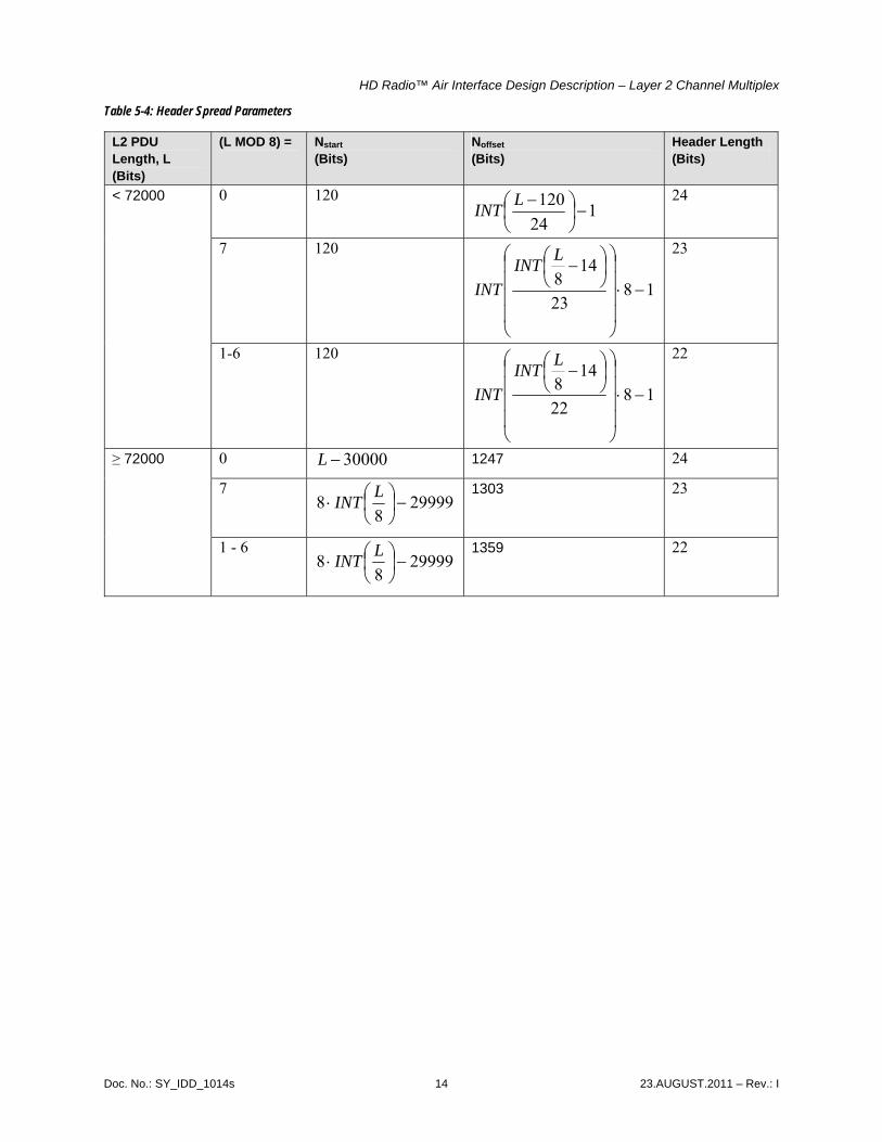
To improve robustness, the PCI bits are evenly spread over most of the Layer 2 PDU, as shown in Figure 5-2. The payload is quantified in units of bytes. Any excess payload that does not constitute a byte is located at the end of the payload. The h0 header bit is offset from the beginning of the transfer frame by Nstart bits. Each remaining header bit is separated from the previous header bit by Noffset bits. Noffset refers to the number of bits between each pair of header bits, exclusive of the header bits themselves.
These numbers depend on the L2 PDU length (in bits), L, as shown in Table 5-4. If the L2 PDU length is an integral number of bytes, the header length is 24 bits. If the L2 PDU length is not an integral number of bytes, the header is shortened to either 23 or 22 bits as shown. If the header length is 23 bits, then h23 is not used. If the header length is 22 bits, then h22 and h23 are not used.
payloadh
Noffset
h h
Noffset Noffset
h h
Noffset
h
h 0 h 1 h 2 h 3 h 22
h 23
payload
Nstart Noffset
...
First Bit Last Bit
payload payload payload payload payload
Figure 5-2: Generic L2 Transfer Frame
Doc. No.: SY_IDD_1014s 13 23.AUGUST.2011 – Rev.: I
HD Radio™ Air Interface Design Description – Layer 2 Channel Multiplex
Table 5-4: Header Spread Parameters
L2 PDU Length, L (Bits)
(L MOD 8) = Nstart
(Bits) Noffset
(Bits) Header Length (Bits)
0 120 1
24120
−⎟⎠⎞
⎜⎝⎛ −LINT
24
7 120
1823
148 −⋅
⎟⎟⎟⎟
⎠
⎞
⎜⎜⎜⎜
⎝
⎛⎟⎠⎞
⎜⎝⎛ −
LINTINT
23
< 72000
1-6 120
1822
148 −⋅
⎟⎟⎟⎟
⎠
⎞
⎜⎜⎜⎜
⎝
⎛⎟⎠⎞
⎜⎝⎛ −
LINTINT
22
0 30000−L 1247 24
7 29999
88 −⎟
⎠⎞
⎜⎝⎛⋅
LINT1303 23
≥ 72000
1 - 6 29999
88 −⎟
⎠⎞
⎜⎝⎛⋅
LINT1359 22
Doc. No.: SY_IDD_1014s 14 23.AUGUST.2011 – Rev.: I

HD Radio™ Air Interface Design Description – Layer 2 Channel Multiplex
5.3 Order of Content
The mix of content from different sources, each having a separate transport mechanism, requires mapping that can be tracked by the receivers under various channel conditions or under various operating scenarios. In addition, established rules for mapping content allow for future introduction of services while maintaining backward compatibility.
The structure of a Layer 2 PDU, as shown in Figure 5-1, indicates the relative placement of audio and data content. For a Layer 2 PDU, the left-most bit is referred to as bit zero (bit 0) and the right-most bit is refered to as MSB. When audio content, opportunistic data, and fixed data are present, the audio content is placed from bit 0, followed by opportunistic data, and then followed by fixed data.
A more inclusive description, as shown in Figure 5-3, emphasizes the spread of the protocol control information (PCI) across the complete Layer 2 bit aggregate. The PCI bits are independent of the payload content and are (logically) placed first, before the rest of the PDU is constructed.
Figure 5-3: Order of Content
Audio-oriented content may include MPS transport and multiple instances of SPS transport. Figure 5-4 provides a detailed description of certain order requirements within the audio content in Layer 2.
Figure 5-4: Layer 2 Order of Multiple Instances of Audio-Oriented Content
MPS transport is always placed first, starting with Layer 2 bit 0. MPS transport is then followed by instances of SPS transport that contain audio that is free-access. Instances of SPS transport that contain audio that is conditionally-accessed are placed last, toward the end of the audio-oriented content. The audio-oriented transport instances are independent. Each instance contains its control information that
Doc. No.: SY_IDD_1014s 15 23.AUGUST.2011 – Rev.: I

HD Radio™ Air Interface Design Description – Layer 2 Channel Multiplex
points to the end of the PDU. Thefore, the control information of the last audio instance points to the end of the entire audio-oriented content.
Data-oriented content (for services) may include opportunistic data services transport and fixed data services transport. Figure 5-5 provides a detailed description of certain order requirements within the data services content in Layer 2.
Figure 5-5: Layer 2 Order of Data Content Control Information
The fixed data services transport PDU is always placed towards the last bit of the Layer 2 PDU. The fixed data transport control information, which is included within the fixed data PDU, points to the end of that PDU.
The opportunistic data PDU immediately follows (counting down bitwise) the fixed data PDU. It may span any instantaneous length and does not necessarily fill the entire gap (i.e., it does not necessarily utilize the instantaneously available bandwidth) towards the audio content. The end of the opportunistic data PDU (lower end bitwise count) is indicated by a Data Delimiter (DDL).
Doc. No.: SY_IDD_1014s 16 23.AUGUST.2011 – Rev.: I

HD Radio™ Air Interface Design Description – Layer 2 Channel Multiplex
6 Layer 2 Processing
6.1 Transmit Processing Description
For each active Layer 1 logical channel, Layer 1 indicates to Layer 2 that it requires an L2 PDU. Based on the parameters defined in the previous section, L2 indicates to the Audio Transport and the AAS Data Transport (AAT) to provide their respective PDUs (MPS, SPS PDU, and AAS PDU) that are to be multiplexed within the L2 PDU to that specific Layer 1 logical channel.
Once Layer 2 has received the input PDUs, it creates the L2 PDU to be sent to the appropriate Layer 1 logical channel by:
1. Creating Layer 2 PCI based on content and encoding
2. Spreading PCI across an L2 PDU
3. Inserting MPS/SPS and AAS PDUs into an L2 PDU around the spread PCI
The upper layers notify L2 what information is available to it.
For a PIDS or SIDS Layer 1 logical channel, Layer 1 indicates to Layer 2 that it requires an L2 PDU. Layer 2 indicates to the SIS Transport to provide its respective PDU. Layer 2 forwards the SIS PDU directly to Layer 1 without any modification.
The HD Radio system provides SIS to all HD Radio receivers. The PIDS and SIDS logical channels are dedicated to transporting SIS that may be acquired quickly for initial screening of provided services and other station-related information.
Doc. No.: SY_IDD_1014s 17 23.AUGUST.2011 – Rev.: I