hdmi 201 user guide · 2019-01-22 · per informazioni su parametri di sicurezza, conformità alle...
TRANSCRIPT

User Guide
HDMI 201
DVI & HDMI Extenders
HDMI Twisted Pair Extender
68-1375-01 Rev. F01 19
Safety InstructionsSafety Instructions • English
WARNING: This symbol, , when used on the product, is intended to alert the user of the presence of uninsulated dangerous voltage within the product’s enclosure that may present a risk of electric shock.
ATTENTION: This symbol, , when used on the product, is intended to alert the user of important operating and maintenance (servicing) instructions in the literature provided with the equipment.
For information on safety guidelines, regulatory compliances, EMI/EMF compatibility, accessibility, and related topics, see the Extron Safety and Regulatory Compliance Guide, part number 68-290-01, on the Extron website, www.extron.com.
Sicherheitsanweisungen • Deutsch
WARNUNG: Dieses Symbol auf dem Produkt soll den Benutzer darauf aufmerksam machen, dass im Inneren des Gehäuses dieses Produktes gefährliche Spannungen herrschen, die nicht isoliert sind und die einen elektrischen Schlag verursachen können.
VORSICHT: Dieses Symbol auf dem Produkt soll dem Benutzer in der im Lieferumfang enthaltenen Dokumentation besonders wichtige Hinweise zur Bedienung und Wartung (Instandhaltung) geben.
Weitere Informationen über die Sicherheitsrichtlinien, Produkthandhabung, EMI/EMF-Kompatibilität, Zugänglichkeit und verwandte Themen finden Sie in den Extron-Richtlinien für Sicherheit und Handhabung (Artikelnummer 68-290-01) auf der Extron-Website, www.extron.com.
Instrucciones de seguridad • Español
ADVERTENCIA: Este símbolo, , cuando se utiliza en el producto, avisa al usuario de la presencia de voltaje peligroso sin aislar dentro del producto, lo que puede representar un riesgo de descarga eléctrica.
ATENCIÓN: Este símbolo, , cuando se utiliza en el producto, avisa al usuario de la presencia de importantes instrucciones de uso y mantenimiento recogidas en la documentación proporcionada con el equipo.
Para obtener información sobre directrices de seguridad, cumplimiento de normativas, compatibilidad electromagnética, accesibilidad y temas relacionados, consulte la Guía de cumplimiento de normativas y seguridad de Extron, referencia 68-290-01, en el sitio Web de Extron, www.extron.com.
Instructions de sécurité • Français
AVERTISSEMENT : Ce pictogramme, , lorsqu’il est utilisé sur le produit, signale à l’utilisateur la présence à l’intérieur du boîtier du produit d’une tension électrique dangereuse susceptible de provoquer un choc électrique.
ATTENTION : Ce pictogramme, , lorsqu’il est utilisé sur le produit, signale à l’utilisateur des instructions d’utilisation ou de maintenance importantes qui se trouvent dans la documentation fournie avec le matériel.
Pour en savoir plus sur les règles de sécurité, la conformité à la réglementation, la compatibilité EMI/EMF, l’accessibilité, et autres sujets connexes, lisez les informations de sécurité et de conformité Extron, réf. 68-290-01, sur le site Extron, www.extron.com.
Istruzioni di sicurezza • Italiano
AVVERTENZA: Il simbolo, , se usato sul prodotto, serve ad avvertire l’utente della presenza di tensione non isolata pericolosa all’interno del contenitore del prodotto che può costituire un rischio di scosse elettriche.
ATTENTZIONE: Il simbolo, , se usato sul prodotto, serve ad avvertire l’utente della presenza di importanti istruzioni di funzionamento e manutenzione nella documentazione fornita con l’apparecchio.
Per informazioni su parametri di sicurezza, conformità alle normative, compatibilità EMI/EMF, accessibilità e argomenti simili, fare riferimento alla Guida alla conformità normativa e di sicurezza di Extron, cod. articolo 68-290-01, sul sito web di Extron, www.extron.com.
Instrukcje bezpieczeństwa • Polska
OSTRZEŻENIE: Ten symbol, , gdy używany na produkt, ma na celu poinformować użytkownika o obecności izolowanego i niebezpiecznego napięcia wewnątrz obudowy produktu, który może stanowić zagrożenie porażenia prądem elektrycznym.
UWAGI: Ten symbol, , gdy używany na produkt, jest przeznaczony do ostrzegania użytkownika ważne operacyjne oraz instrukcje konserwacji (obsługi) w literaturze, wyposażone w sprzęt.
Informacji na temat wytycznych w sprawie bezpieczeństwa, regulacji wzajemnej zgodności, zgodność EMI/EMF, dostępności i Tematy pokrewne, zobacz Extron bezpieczeństwa i regulacyjnego zgodności przewodnik, część numer 68-290-01, na stronie internetowej Extron, www.extron.com.
Инструкция по технике безопасности • Русский
ПРЕДУПРЕЖДЕНИЕ: Данный символ, , если указан на продукте, предупреждает пользователя о наличии неизолированного опасного напряжения внутри корпуса продукта, которое может привести к поражению электрическим током.
ВНИМАНИЕ: Данный символ, , если указан на продукте, предупреждает пользователя о наличии важных инструкций по эксплуатации и обслуживанию в руководстве, прилагаемом к данному оборудованию.
Для получения информации о правилах техники безопасности, соблюдении нормативных требований, электромагнитной совместимости (ЭМП/ЭДС), возможности доступа и других вопросах см. руководство по безопасности и соблюдению нормативных требований Extron на сайте Extron: , www.extron.com, номер по каталогу - 68-290-01.
安全说明 • 简体中文
警告: 产品上的这个标志意在警告用户该产品机壳内有暴露的危险 电压,有触电危险。
注意: 产品上的这个标志意在 提示用户设备随附的用户手册中有 重要的操作和维护(维修)说明。
关于我们产品的安全指南、遵循的规范、EMI/EMF 的兼容性、无障碍 使用的特性等相关内容,敬请访问 Extron 网站 , www.extron.com,参见
Extron 安全规范指南,产品编号 68-290-01。
안전 지침 • 한국어
경고: 이 기호 가 제품에 사용될 경우, 제품의 인클로저 내에 있는 접지되지 않은 위험한 전류로 인해 사용자가 감전될 위험이 있음을 경고합니다.
주의: 이 기호 가 제품에 사용될 경우, 장비와 함께 제공된 책자에 나와 있는 주요 운영 및 유지보수(정비) 지침을 경고합니다.
안전 가이드라인, 규제 준수, EMI/EMF 호환성, 접근성, 그리고 관련 항목에 대한 자세한 내용은 Extron 웹 사이트(www.extron.com)의 Extron 안전 및 규제 준수 안내서, 68-290-01 조항을 참조하십시오.
安全記事 • 繁體中文
警告: 若產品上使用此符號,是為了提醒使用者,產品機殼內存在著 可能會導致觸電之風險的未絕緣危險電壓。
注意 若產品上使用此符號,是為了提醒使用者,設備隨附的用戶手冊中有重要的操作和維護(維修)説明。
有關安全性指導方針、法規遵守、EMI/EMF 相容性、存取範圍和相關主題的詳細資訊,請瀏覽 Extron 網站:www.extron.com,然後參閱《Extron 安全性與法規遵守手冊》,準則編號 68-290-01。
安全上のご注意 • 日本語
警告: この記号 が製品上に表示されている場合は、筐体内に絶縁されて いない高電圧が流れ、感電の危険があることを示しています。
注意:この記号 が製品上に表示されている場合は、本機の取扱説明書に 記載されている重要な操作と保守(整備)の指示についてユーザーの注意を喚起するものです。
安全上のご注意、法規厳守、EMI/EMF適合性、その他の関連項目に ついては、エクストロンのウェブサイト www.extron.com より 『Extron Safety and Regulatory Compliance Guide』 (P/N 68-290-01) をご覧ください。
Copyright© 2019 Extron Electronics. All rights reserved.
TrademarksAll trademarks mentioned in this guide are the properties of their respective owners.The following registered trademarks(®), registered service marks(SM), and trademarks(TM) are the property of RGB Systems, Inc. or Extron Electronics (see the current list of trademarks on the Terms of Use page at www.extron.com):
Registered Trademarks (®)
Extron, AVTrac, Cable Cubby, ControlScript, CrossPoint, DTP, eBUS, EDID Manager, EDID Minder, Flat Field, FlexOS, Global Configurator, Global Scripter, GlobalViewer, Hideaway, Inline, IP Intercom, IP Link, Key Minder, LinkLicense, LockIt, MediaLink, MediaPort, NetPA, PlenumVault, PoleVault, PowerCage, PURE3, Quantum, SoundField, SpeedMount, SpeedSwitch, System INTEGRATOR, TeamWork, TouchLink, V-Lock, VersaTools, VN-Matrix, VoiceLift, WallVault, WindoWall, XTP, and XTP Systems
Registered Service Mark(SM) : S3 Service Support Solutions
Trademarks (™)
AAP, AFL (Accu-Rate Frame Lock), ADSP (Advanced Digital Sync Processing), Auto-Image, CableCover, CDRS (Class D Ripple Suppression), DDSP (Digital Display Sync Processing), DMI (Dynamic Motion Interpolation), Driver Configurator, DSP Configurator, DSVP (Digital Sync Validation Processing), eLink, EQIP, EverLast, FastBite, FOX, FOXBOX, HyperLane, IP Intercom HelpDesk, MAAP, MicroDigital, Opti-Torque, ProDSP, QS-FPC (QuickSwitch Front Panel Controller), Room Agent, Scope-Trigger, ShareLink, SIS, Simple Instruction Set, Skew-Free, SpeedNav, Triple-Action Switching, True4K, Vector™ 4K , WebShare, XTRA, ZipCaddy, and ZipClip
FCC Class A NoticeThis equipment has been tested and found to comply with the limits for a Class A digital device, pursuant to part 15 of the FCC rules. The Class A limits provide reasonable protection against harmful interference when the equipment is operated in a commercial environment. This equipment generates, uses, and can radiate radio frequency energy and, if not installed and used in accordance with the instruction manual, may cause harmful interference to radio communications. Operation of this equipment in a residential area is likely to cause interference. This interference must be corrected at the expense of the user.
NOTES:
• This unit was tested with shielded I/O cables on the peripheral devices. Shielded cables must be used to ensure compliance with FCC emissions limits.
• For more information on safety guidelines, regulatory compliances, EMI/EMF compatibility, accessibility, and related topics, see the “Extron Safety and Regulatory Compliance Guide” on the Extron website.
Conventions Used in this Guide
Notifications
The following notifications are used in this guide:
WARNING: Potential risk of severe injury or death.
AVERTISSEMENT : Risque potentiel de blessure grave ou de mort.
CAUTION: Risk of minor personal injury.
ATTENTION : Risque de blessure mineure.
NOTE: A note draws attention to important information.
Specifications Availability
Product specifications are available on the Extron website, www.extron.com.
Extron Glossary of TermsA glossary of terms is available at http://www.extron.com/technology/glossary.aspx.
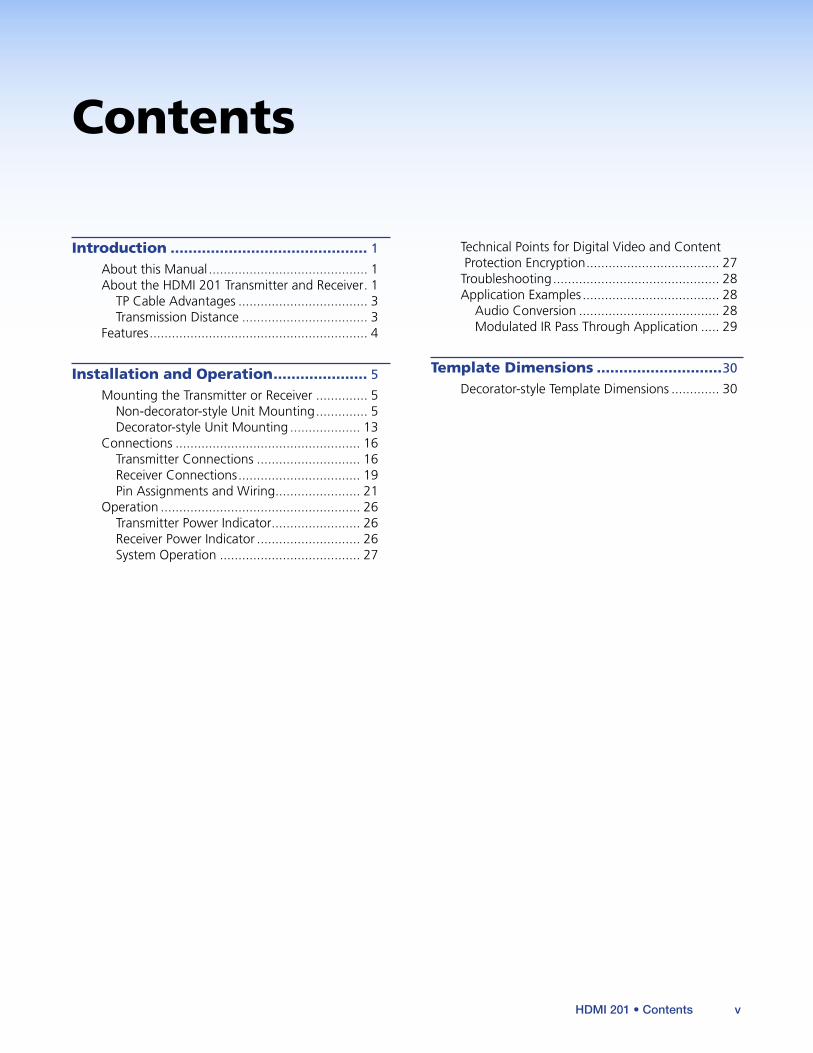
Contents
Introduction ............................................ 1
About this Manual ........................................... 1About the HDMI 201 Transmitter and Receiver . 1
TP Cable Advantages ................................... 3Transmission Distance .................................. 3
Features ........................................................... 4
Installation and Operation ..................... 5
Mounting the Transmitter or Receiver .............. 5Non-decorator-style Unit Mounting .............. 5Decorator-style Unit Mounting ................... 13
Connections .................................................. 16Transmitter Connections ............................ 16Receiver Connections ................................. 19Pin Assignments and Wiring ....................... 21
Operation ...................................................... 26Transmitter Power Indicator ........................ 26Receiver Power Indicator ............................ 26System Operation ...................................... 27
Technical Points for Digital Video and Content Protection Encryption .................................... 27
Troubleshooting ............................................. 28Application Examples ..................................... 28
Audio Conversion ...................................... 28Modulated IR Pass Through Application ..... 29
Template Dimensions ............................30
Decorator-style Template Dimensions ............. 30
HDMI 201 • Contents v

HDMI 201 • Contents vi

Introduction
• About this Manual
• About the HDMI 201 Transmitter and Receiver
• Features
About this ManualThis manual describes the Extron HDMI 201 family of High Definition Multimedia Interface (HDMI™) Extenders, which consists of HDMI 201 Tx transmitters and HDMI 201 Rx receivers. This manual describes how to install, operate, and configure them.
About the HDMI 201 Transmitter and ReceiverThe Extron HDMI 201 Tx/Rx is a family of HDMI transmitters and receivers (figure 1), in enclosures that support different mounting options. A transmitter and receiver pair extends the usable distance of DVI or HDMI digital video and RS-232 control signals over two Category (CAT) 5/5e/6 unshielded twisted pair (UTP) or shielded twisted pair (STP) cables. Extron DTP26 digital cable is also recommended. The HDMI 201 A D transmitter and receiver also route audio, but not on the TP link. The video and control (and audio, if applicable) signals can be transmitted up to 200 feet (60 m).
POWER
12V
0.4A MAX
HDMI 201 Rx
1
2
HDMI OUTPUT
RS-232
PASS THRU
Tx Rx
POWER
12V
0.4A MAX
HDMI 201 Tx
RS-232
PASS THRU
Tx Rx
1
2
HDMI INPUT
DVD
Plasma Display
ExtronHDMI 201 TxTransmitter
ExtronHDMI 201 RxReceiver
HDMI Cable
HDMI Cable
RS-232Control
CAT 5/5e/6 UTPup to 200’
Figure 1. Typical Transmitter and Receiver Application
An HDMI 201 system consists of a transmitter (Tx) and a receiver (Rx). The pair can handle a single link of HDMI digital video and a bidirectional RS-232 link. The HDMI 201 A D also converts a computer audio input into balanced or unbalanced stereo audio output.
HDMI 201 • Introduction 1
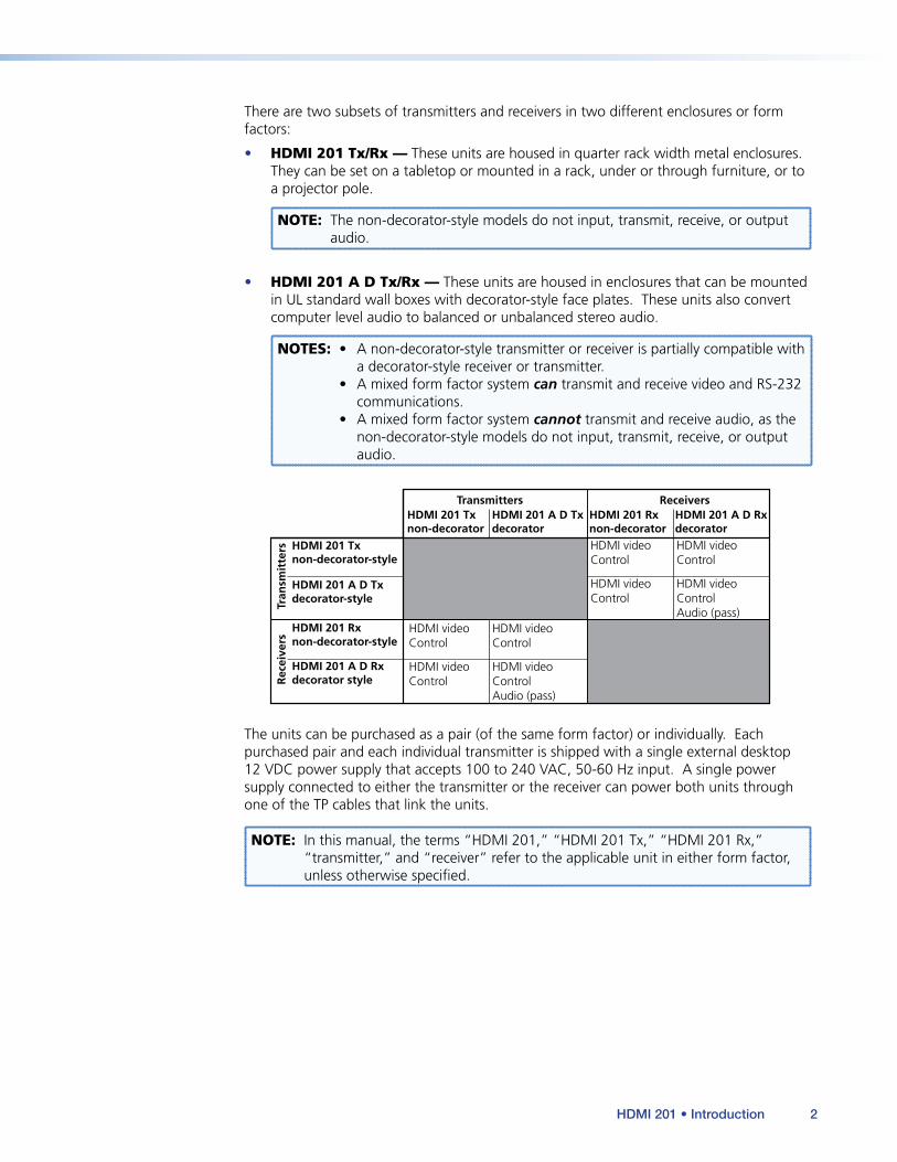
There are two subsets of transmitters and receivers in two different enclosures or form factors:
• HDMI 201 Tx/Rx — These units are housed in quarter rack width metal enclosures. They can be set on a tabletop or mounted in a rack, under or through furniture, or to a projector pole.
NOTE: The non-decorator-style models do not input, transmit, receive, or output audio.
• HDMI 201 A D Tx/Rx — These units are housed in enclosures that can be mounted in UL standard wall boxes with decorator-style face plates. These units also convert computer level audio to balanced or unbalanced stereo audio.
NOTES: • A non-decorator-style transmitter or receiver is partially compatible with a decorator-style receiver or transmitter.
• A mixed form factor system can transmit and receive video and RS-232 communications.
• A mixed form factor system cannot transmit and receive audio, as the non-decorator-style models do not input, transmit, receive, or output audio.
HDMI 201 Txnon-decorator
Transmitters
Tran
smit
ters
Rec
eive
rs
Receivers
HDMI 201 Txnon-decorator-style
HDMI videoControl
HDMI videoControl
HDMI 201 A D Txdecorator-style
HDMI 201 Rxnon-decorator-style
HDMI 201 A D Rxdecorator style
HDMI 201 A D Txdecorator
HDMI 201 Rxnon-decorator
HDMI 201 A D Rxdecorator
HDMI videoControl
HDMI videoControlAudio (pass)
HDMI videoControl
HDMI videoControl
HDMI videoControl
HDMI videoControlAudio (pass)
The units can be purchased as a pair (of the same form factor) or individually. Each purchased pair and each individual transmitter is shipped with a single external desktop 12 VDC power supply that accepts 100 to 240 VAC, 50-60 Hz input. A single power supply connected to either the transmitter or the receiver can power both units through one of the TP cables that link the units.
NOTE: In this manual, the terms “HDMI 201,” “HDMI 201 Tx,” “HDMI 201 Rx,” “transmitter,” and “receiver” refer to the applicable unit in either form factor, unless otherwise specified.
HDMI 201 • Introduction 2
TP Cable Advantages
Twisted pair cable is much smaller, lighter, more flexible, and less expensive than coaxial or HDMI cable. These transmitter and receiver twisted pair (TP) products make cable runs simpler and less cumbersome. Termination of the cable with RJ-45 connectors is simple, quick, and economical.
NOTES: • The transmitter and receiver pair works with unshielded twisted pair (UTP) or shielded twisted pair (STP) cables; but, to ensure FCC Class A and CE compliance, STP cables are required.
• Do not use Extron UTP23SF-4 Enhanced Skew-Free™ A/V UTP cable to link the transmitter and receiver. Skew-free A/V cable was designed for most Extron TP transmitter/receiver applications, but the HDMI 201 Tx/Rx does not work properly with this cable.
Control Communications
The RS-232 or infrared (IR) communications are pass-through only; the transmitter and receiver do not generate or respond to these signals.
Transmission Distance
The maximum transmission distance is determined by the resolution of the signal and the TP cable that is used.
• With CAT 5/5e/6 unshielded TP cable, the Tx/Rx pair can transmit and receive 720p and 1080i HDTV or XGA video signals up to 200 feet (60 m) and 1080p HDTV or UXGA video up to 100 feet (30 m).
• With CAT 5/5e/6 shielded TP cable, the Tx/Rx pair can transmit and receive 720p and 1080i HDTV or XGA video signals up to 200 feet (60 m) and 1080p HDTV or UXGA video up to 125 feet (38 m).
NOTES: • The transmission distance varies greatly, depending on the signal resolution, type of cable used, graphics card, and display used in the system.
• For resolutions of 1600x1200, 1920x1200, and 1080p, Extron strongly recommends DTP26 cable, or equivalent. Extron DTP26 cable consists of four individually shielded copper pairs and an overall braided shield that help reduce crosstalk. DTP26 cable extends these resolutions up to 150 feet (45 m).
HDMI 201 • Introduction 3
FeaturesTransmits single link HDMI signals over two CAT 5/5e/6 cables — Standard twisted pair cables provide an economical, easily installed cable solution.
Supports DDC and HDCP copy protection transmission — The Tx/Rx pair fully supports long distance transmission of the DDC and HDCP signals.
Control communications pass-through — Bidirectional RS-232 or IR control signals can be transmitted alongside the HDMI signal, so that the remote display can be controlled without the need for additional cabling.
Audio routing — The HDMI 201 A D Tx/Rx also routes unbalanced stereo audio when both units are the decorator-style form factor.
Supports CEC signal transmission
1-inch high, quarter rack width, metal enclosures (HDMI 201 Tx and HDMI 201 Rx [non-decorator-style] only)— With low profile enclosures, both transmitter models and both receiver models can be discreetly installed in locations such as behind a plasma or LCD flat-panel display.
Wall-mountable enclosures (HDMI 201 A D Tx and HDMI 201 A D Rx [decorator-style] only)
External 100 VAC to 240 VAC, 50-60 Hz, international power supply — Included with units sold as a paired system and with transmitters
Remote powering of transmitter or receiver — Only one power supply is necessary to power both devices.
HDMI 201 • Introduction 4
Installation and Operation
This section describes the installation and the operation of the HDMI 201, including:
• Mounting the Transmitter or Receiver
• Connections
• Operation
• Technical Points for Digital Video and Content Protection Encryption
• Troubleshooting
• Application Examples
Mounting the Transmitter or Receiver
ATTENTION:
• Installation and service must be performed by authorized personnel only.
• L’installation et l’entretien doivent être effectués par le personnel autorisé uniquement.
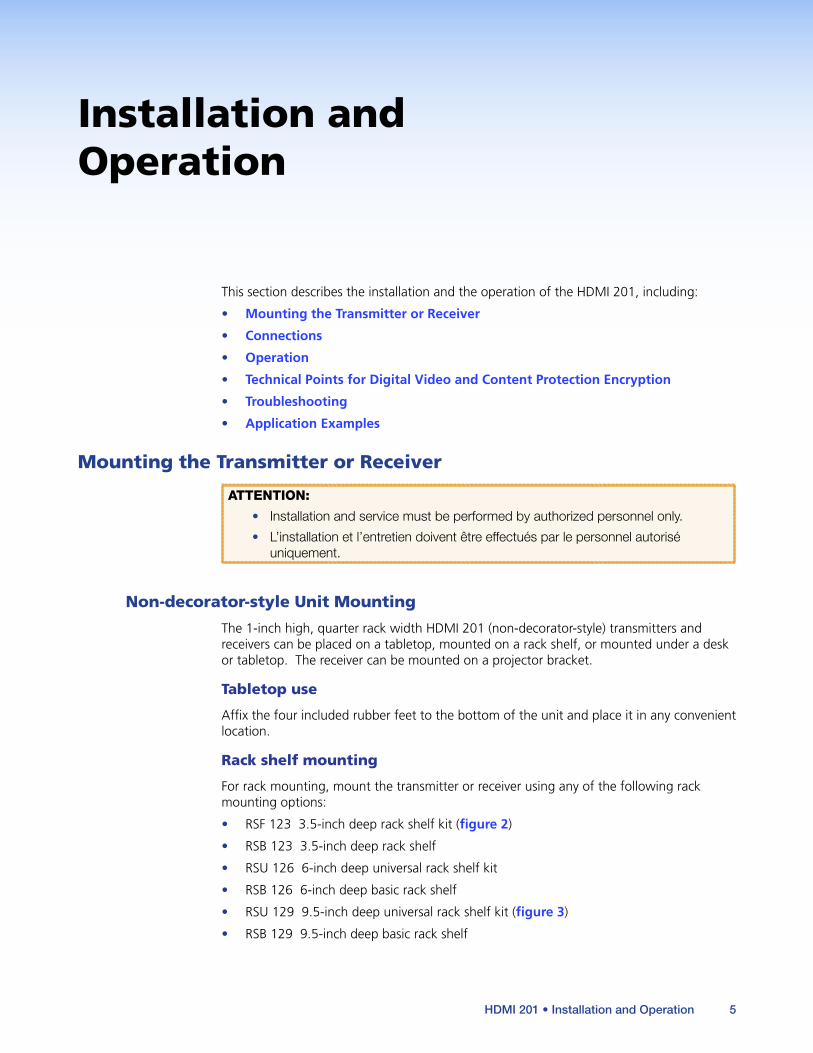
Non-decorator-style Unit Mounting
The 1-inch high, quarter rack width HDMI 201 (non-decorator-style) transmitters and receivers can be placed on a tabletop, mounted on a rack shelf, or mounted under a desk or tabletop. The receiver can be mounted on a projector bracket.
Tabletop use
Affix the four included rubber feet to the bottom of the unit and place it in any convenient location.
Rack shelf mounting
For rack mounting, mount the transmitter or receiver using any of the following rack mounting options:
• RSF 123 3.5-inch deep rack shelf kit (figure 2)
• RSB 123 3.5-inch deep rack shelf
• RSU 126 6-inch deep universal rack shelf kit
• RSB 126 6-inch deep basic rack shelf
• RSU 129 9.5-inch deep universal rack shelf kit (figure 3)
• RSB 129 9.5-inch deep basic rack shelf
HDMI 201 • Installation and Operation 5
UL guidelines for rack mounting
The following Underwriters Laboratories (UL) guidelines pertain to the installation of an HDMI 201 unit onto a rack.
1. Elevated operating ambient — If installed in a closed or multi-unit rack assembly, the operating ambient temperature of the rack environment may be greater than room ambient. Therefore, consider installing the equipment in an environment compatible with the maximum ambient temperature specified by the manufacturer [Tma = +32 to +122 °F (0 to +50 °C)].
2. Reduced air flow — Installation of the equipment in a rack should be such that the amount of air flow required for safe operation of the equipment is not compromised.
3. Mechanical loading — Mounting of the equipment in the rack should be such that a hazardous condition is not achieved due to uneven mechanical loading.
4. Circuit overloading — Consideration should be given to the connection of the equipment to the supply circuit and the effect that overloading of the circuits might have on overcurrent protection and supply wiring. Appropriate consideration of equipment nameplate ratings should be used when addressing this concern.
5. Reliable earthing (grounding) — Reliable earthing of rack-mounted equipment should be maintained. Particular attention should be given to supply connections other than direct connections to the branch circuit (such as the use of power strips).
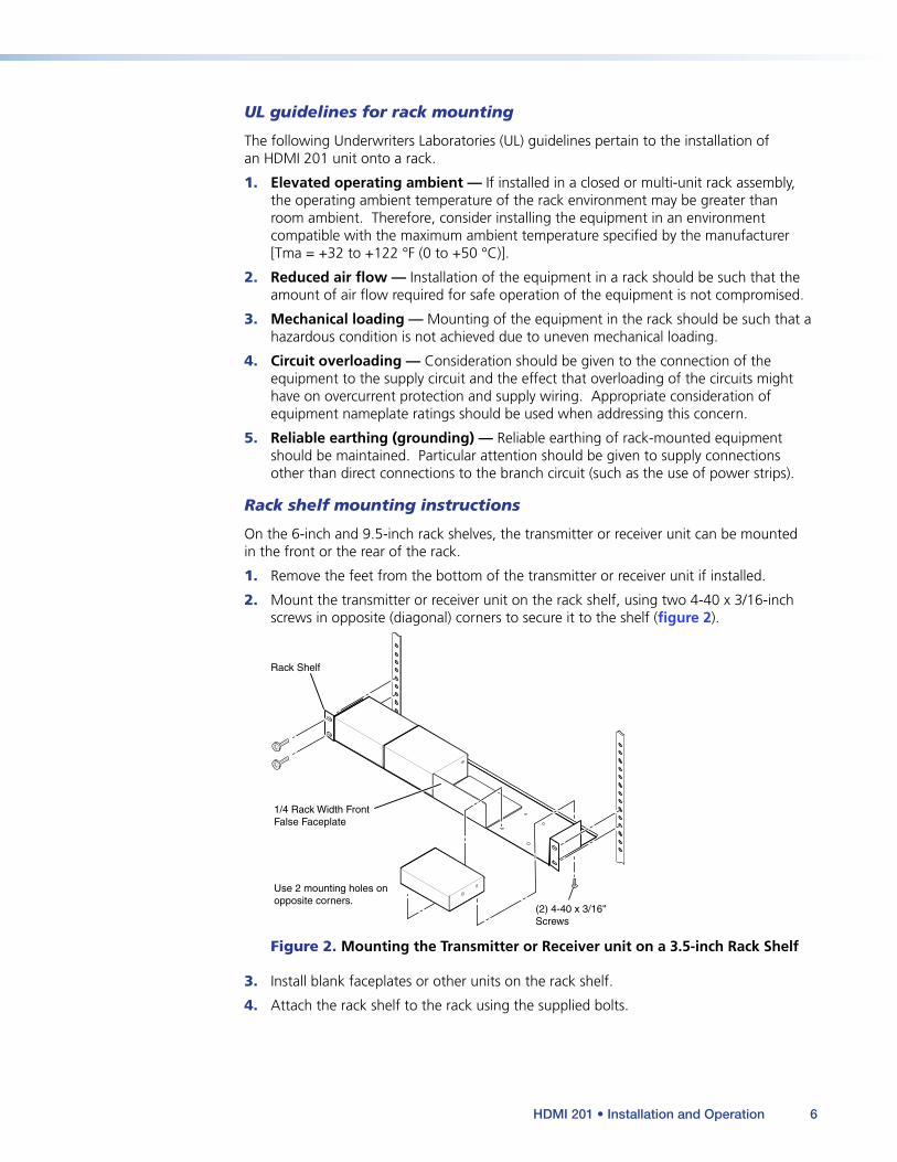
Rack shelf mounting instructions
On the 6-inch and 9.5-inch rack shelves, the transmitter or receiver unit can be mounted in the front or the rear of the rack.
1. Remove the feet from the bottom of the transmitter or receiver unit if installed.
2. Mount the transmitter or receiver unit on the rack shelf, using two 4-40 x 3/16-inch screws in opposite (diagonal) corners to secure it to the shelf (figure 2).
(2) 4-40 x 3/16" Screws
Use 2 mounting holes on opposite corners.
Rack Shelf
1/4 Rack Width Front False Faceplate
Figure 2. Mounting the Transmitter or Receiver unit on a 3.5-inch Rack Shelf
3. Install blank faceplates or other units on the rack shelf.
4. Attach the rack shelf to the rack using the supplied bolts.
HDMI 201 • Installation and Operation 6
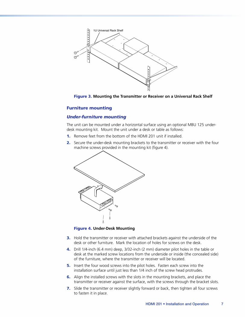
1U Universal Rack Shelf
Figure 3. Mounting the Transmitter or Receiver on a Universal Rack Shelf
Furniture mounting
Under-furniture mounting
The unit can be mounted under a horizontal surface using an optional MBU 125 under-desk mounting kit. Mount the unit under a desk or table as follows:
1. Remove feet from the bottom of the HDMI 201 unit if installed.
2. Secure the under-desk mounting brackets to the transmitter or receiver with the four machine screws provided in the mounting kit (figure 4).
Figure 4. Under-Desk Mounting
3. Hold the transmitter or receiver with attached brackets against the underside of the desk or other furniture. Mark the location of holes for screws on the desk.
4. Drill 1/4-inch (6.4 mm) deep, 3/32-inch (2 mm) diameter pilot holes in the table or desk at the marked screw locations from the underside or inside (the concealed side) of the furniture, where the transmitter or receiver will be located.
5. Insert the four wood screws into the pilot holes. Fasten each screw into the installation surface until just less than 1/4 inch of the screw head protrudes.
6. Align the installed screws with the slots in the mounting brackets, and place the transmitter or receiver against the surface, with the screws through the bracket slots.
7. Slide the transmitter or receiver slightly forward or back, then tighten all four screws to fasten it in place.
HDMI 201 • Installation and Operation 7
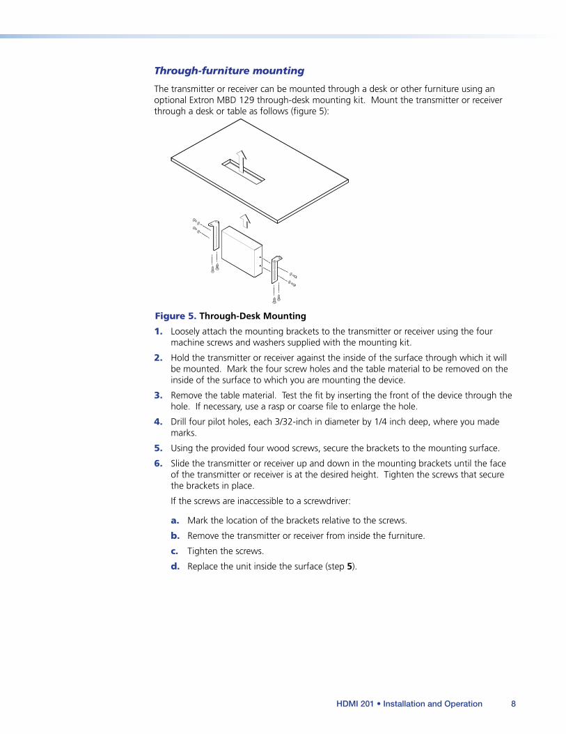
Through-furniture mounting
The transmitter or receiver can be mounted through a desk or other furniture using an optional Extron MBD 129 through-desk mounting kit. Mount the transmitter or receiver through a desk or table as follows (figure 5):
Figure 5. Through-Desk Mounting
1. Loosely attach the mounting brackets to the transmitter or receiver using the four machine screws and washers supplied with the mounting kit.
2. Hold the transmitter or receiver against the inside of the surface through which it will be mounted. Mark the four screw holes and the table material to be removed on the inside of the surface to which you are mounting the device.
3. Remove the table material. Test the fit by inserting the front of the device through the hole. If necessary, use a rasp or coarse file to enlarge the hole.
4. Drill four pilot holes, each 3/32-inch in diameter by 1/4 inch deep, where you made marks.
5. Using the provided four wood screws, secure the brackets to the mounting surface.
6. Slide the transmitter or receiver up and down in the mounting brackets until the face of the transmitter or receiver is at the desired height. Tighten the screws that secure the brackets in place.
If the screws are inaccessible to a screwdriver:
a. Mark the location of the brackets relative to the screws.
b. Remove the transmitter or receiver from inside the furniture.
c. Tighten the screws.
d. Replace the unit inside the surface (step 5).
HDMI 201 • Installation and Operation 8
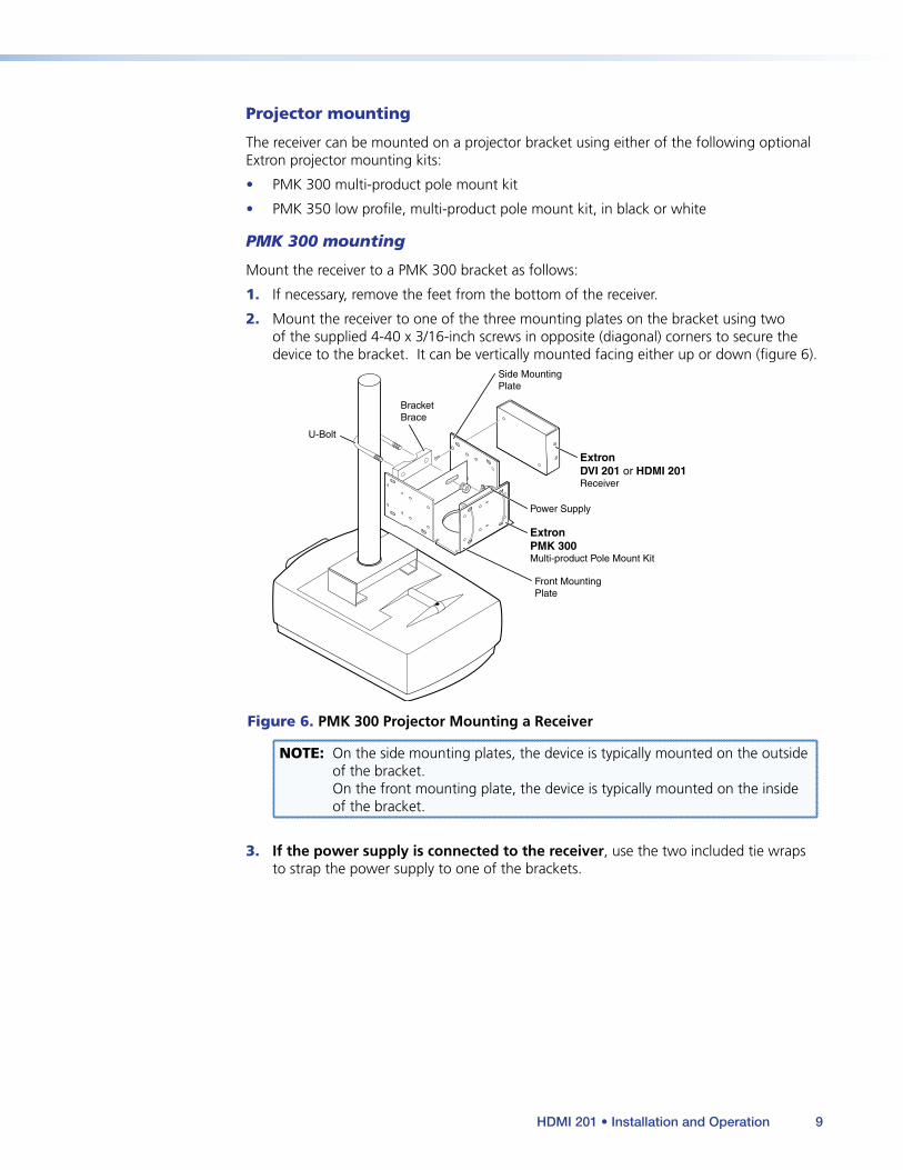
Projector mounting
The receiver can be mounted on a projector bracket using either of the following optional Extron projector mounting kits:
• PMK 300 multi-product pole mount kit
• PMK 350 low profile, multi-product pole mount kit, in black or white
PMK 300 mounting
Mount the receiver to a PMK 300 bracket as follows:
1. If necessary, remove the feet from the bottom of the receiver.
2. Mount the receiver to one of the three mounting plates on the bracket using two of the supplied 4-40 x 3/16-inch screws in opposite (diagonal) corners to secure the device to the bracket. It can be vertically mounted facing either up or down (figure 6).
ExtronPMK 300Multi-product Pole Mount Kit
U-Bolt
Front MountingPlate
Side MountingPlate
ExtronDVI 201 or HDMI 201Receiver
Power Supply
BracketBrace
Figure 6. PMK 300 Projector Mounting a Receiver
NOTE: On the side mounting plates, the device is typically mounted on the outside of the bracket. On the front mounting plate, the device is typically mounted on the inside of the bracket.
3. If the power supply is connected to the receiver, use the two included tie wraps to strap the power supply to one of the brackets.
HDMI 201 • Installation and Operation 9

NOTE: The PMK 300 has a hole in the bottom plate that allows the projector pole to be inserted through the center of the plate (figure 7), rather than outside of the plate (figure 6). To install the PMK 300 in this configuration, slide the bracket up from the bottom of the pole before the projector is installed on the pole.
U-Bolt ExtronPMK 300Multi-product PoleMount Kit
BracketBrace
Figure 7. Projector Pole on the Inside
4. Place the contoured bracket brace against the pole and opposite the back plate. The pole should fit snugly into the depression in the center of the bracket brace.
5. Place the U-bolt around the ceiling pole. Insert the two legs of the U-bolt through the round holes on the contoured bracket brace and then through the slotted holes on the mounting plate on the bracket.
NOTE: The supplied U-bolt fits a typical (1.5 inch to 2.0 inch diameter) ceiling pole.
HDMI 201 • Installation and Operation 10
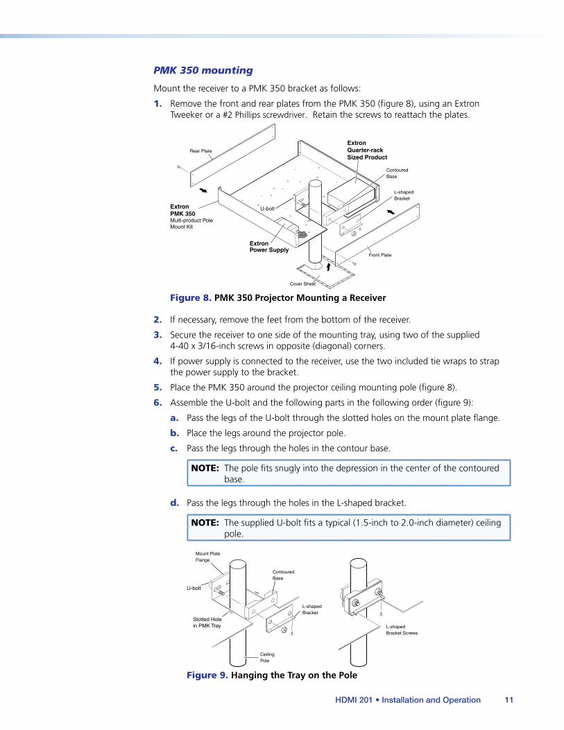
PMK 350 mounting
Mount the receiver to a PMK 350 bracket as follows:
1. Remove the front and rear plates from the PMK 350 (figure 8), using an Extron Tweeker or a #2 Phillips screwdriver. Retain the screws to reattach the plates.
ExtronPMK 350Multi-product PoleMount Kit
Cover Sheet
Front Plate
Rear Plate
U-bolt
L-shapedBracket
ContouredBase
ExtronPower Supply
ExtronQuarter-rackSized Product
Figure 8. PMK 350 Projector Mounting a Receiver
2. If necessary, remove the feet from the bottom of the receiver.
3. Secure the receiver to one side of the mounting tray, using two of the supplied 4-40 x 3/16-inch screws in opposite (diagonal) corners.
4. If power supply is connected to the receiver, use the two included tie wraps to strap the power supply to the bracket.
5. Place the PMK 350 around the projector ceiling mounting pole (figure 8).
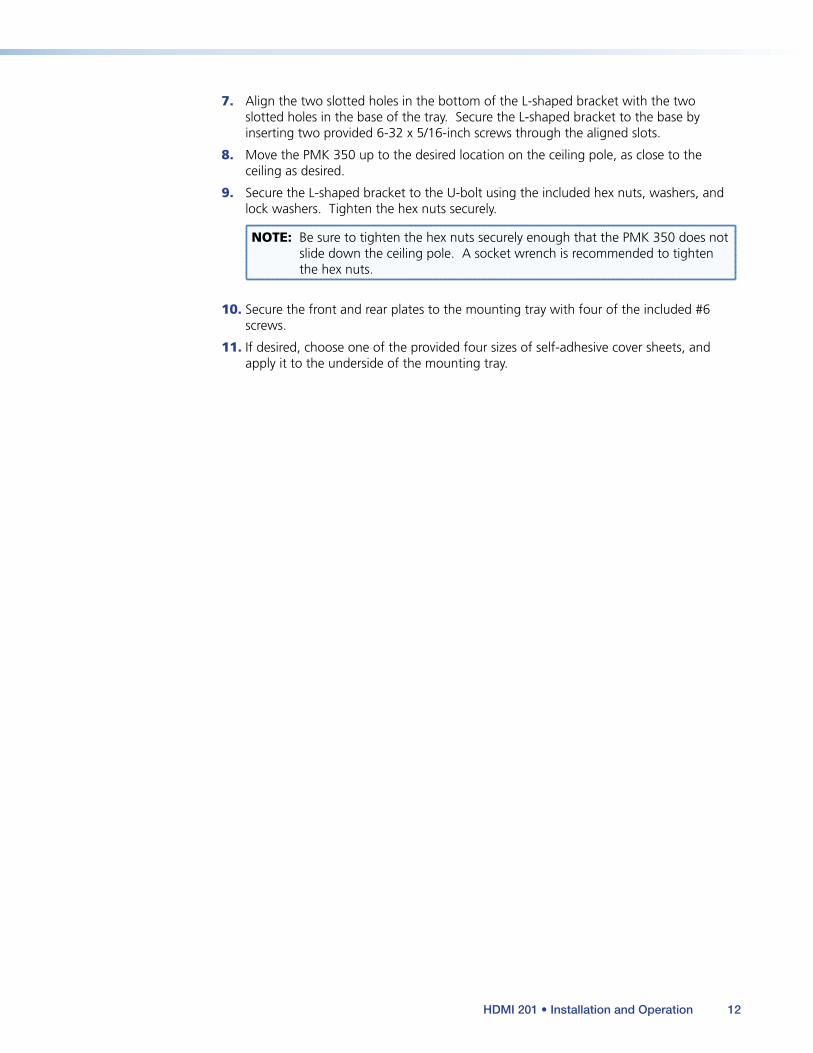
6. Assemble the U-bolt and the following parts in the following order (figure 9):
a. Pass the legs of the U-bolt through the slotted holes on the mount plate flange.
b. Place the legs around the projector pole.
c. Pass the legs through the holes in the contour base.
NOTE: The pole fits snugly into the depression in the center of the contoured base.
d. Pass the legs through the holes in the L-shaped bracket.
NOTE: The supplied U-bolt fits a typical (1.5-inch to 2.0-inch diameter) ceiling pole.
U-bolt
Slotted Holein PMK Tray
L-shapedBracket
L-shapedBracket Screws
ContouredBase
CeilingPole
Mount PlateFlange
Figure 9. Hanging the Tray on the Pole
HDMI 201 • Installation and Operation 11
7. Align the two slotted holes in the bottom of the L-shaped bracket with the two slotted holes in the base of the tray. Secure the L-shaped bracket to the base by inserting two provided 6-32 x 5/16-inch screws through the aligned slots.
8. Move the PMK 350 up to the desired location on the ceiling pole, as close to the ceiling as desired.
9. Secure the L-shaped bracket to the U-bolt using the included hex nuts, washers, and lock washers. Tighten the hex nuts securely.
NOTE: Be sure to tighten the hex nuts securely enough that the PMK 350 does not slide down the ceiling pole. A socket wrench is recommended to tighten the hex nuts.
10. Secure the front and rear plates to the mounting tray with four of the included #6 screws.
11. If desired, choose one of the provided four sizes of self-adhesive cover sheets, and apply it to the underside of the mounting tray.
HDMI 201 • Installation and Operation 12

Decorator-style Unit Mounting
The HDMI 201 A D transmitter and receiver can be installed in a one-gang electrical wall box with a decorator-style wall plate cover (supplied).
The installation must conform to national and local electrical codes and to the size requirements of the wall plate.
UL/safety guidelines
The following Underwriters Laboratories (UL) guidelines pertain to the installation of the decorator-style transmitters and receivers into a wall or furniture.
1. These units are not to be connected to a centralized DC power source or used beyond their rated voltage range.
2. These units must be installed in UL listed junction boxes.
3. These units must be installed with conduit in accordance with National Electrical Code.
Preparing the site and installing the wall box
Choose a location that allows cable runs without interference. Allow enough depth for both the wall box and the cables. The box should be at least 2.5 inches (6.4 cm) deep to accommodate the connectors and cables. Install the cables into the wall, furniture, or conduits before installing the wall plate.
NOTE: The decorator-style units are very deep and have connectors on the back side (figure 10). Extron recommends its 1-gang or 2-gang junction boxes, which have a depth of 2.5 inches (6.4 cm).
2.50” [63.5mm]
1.51” [38.48mm]
1.85” [47mm]
Junction Box
TP Cable(no boot)
TP Cable(no boot)
CaptiveScrewConnectors
Figure 10. Decorator-style Unit Depth Profile
To install a new wall box, perform steps 1 through 9 on the next page. If a suitable wall box is already installed, perform steps 6 through 9 on the next page. UL listed wall boxes are recommended.
HDMI 201 • Installation and Operation 13
1. If a wall box is not available to use for a template, see the dimensions on page 35 to create a template. If installing directly into furniture, cut out the center portion of your template.
2. Place the wall box (or your template) against the installation surface, and mark the opening guidelines.
3. Cut out the material from the marked area.
4. Insert the wall box into the opening. The rear connectors on the box or wall plate should fit easily into the opening. Enlarge or smooth the edges of the opening if needed.
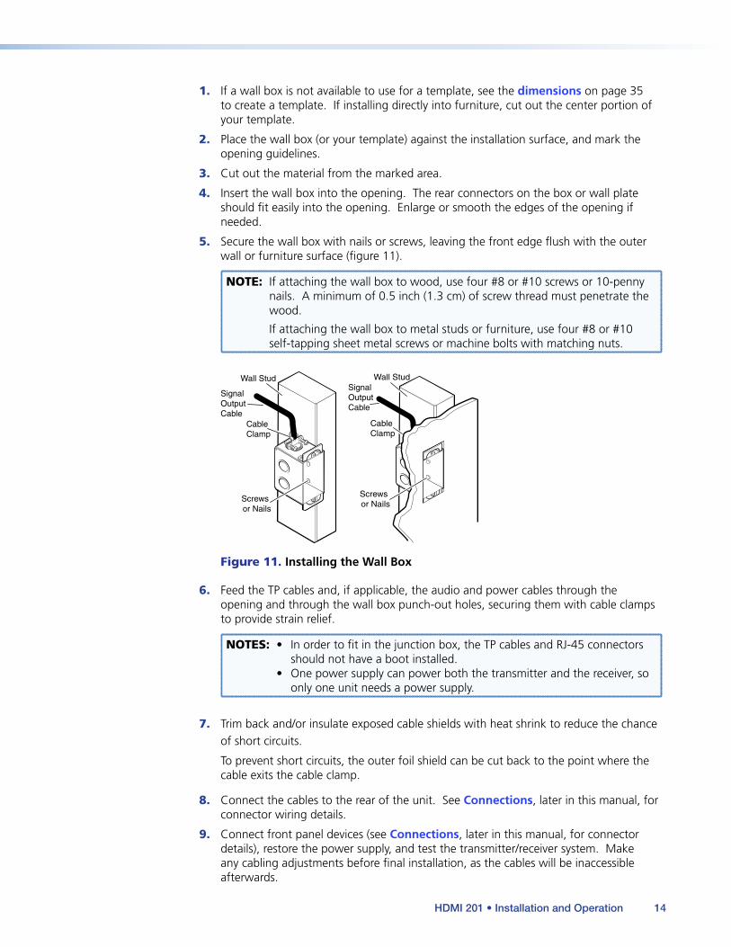
5. Secure the wall box with nails or screws, leaving the front edge flush with the outer wall or furniture surface (figure 11).
NOTE: If attaching the wall box to wood, use four #8 or #10 screws or 10-penny nails. A minimum of 0.5 inch (1.3 cm) of screw thread must penetrate the wood.
If attaching the wall box to metal studs or furniture, use four #8 or #10 self-tapping sheet metal screws or machine bolts with matching nuts.
Signal Output Cable
Cable Clamp
Wall Stud
Screws or Nails
Wall Stud
Cable Clamp
Screws or Nails
Signal Output Cable
Figure 11. Installing the Wall Box
6. Feed the TP cables and, if applicable, the audio and power cables through the opening and through the wall box punch-out holes, securing them with cable clamps to provide strain relief.
NOTES: • In order to fit in the junction box, the TP cables and RJ-45 connectors should not have a boot installed.
• One power supply can power both the transmitter and the receiver, so only one unit needs a power supply.
7. Trim back and/or insulate exposed cable shields with heat shrink to reduce the chance of short circuits.
To prevent short circuits, the outer foil shield can be cut back to the point where the cable exits the cable clamp.
8. Connect the cables to the rear of the unit. See Connections, later in this manual, for connector wiring details.
9. Connect front panel devices (see Connections, later in this manual, for connector details), restore the power supply, and test the transmitter/receiver system. Make any cabling adjustments before final installation, as the cables will be inaccessible afterwards.
HDMI 201 • Installation and Operation 14
Final installation
After testing and making any adjustments, do the following:
1. At the power outlet, unplug the power supply.
NOTE: One power supply can power both the transmitter and the receiver, so only one unit needs a power supply.
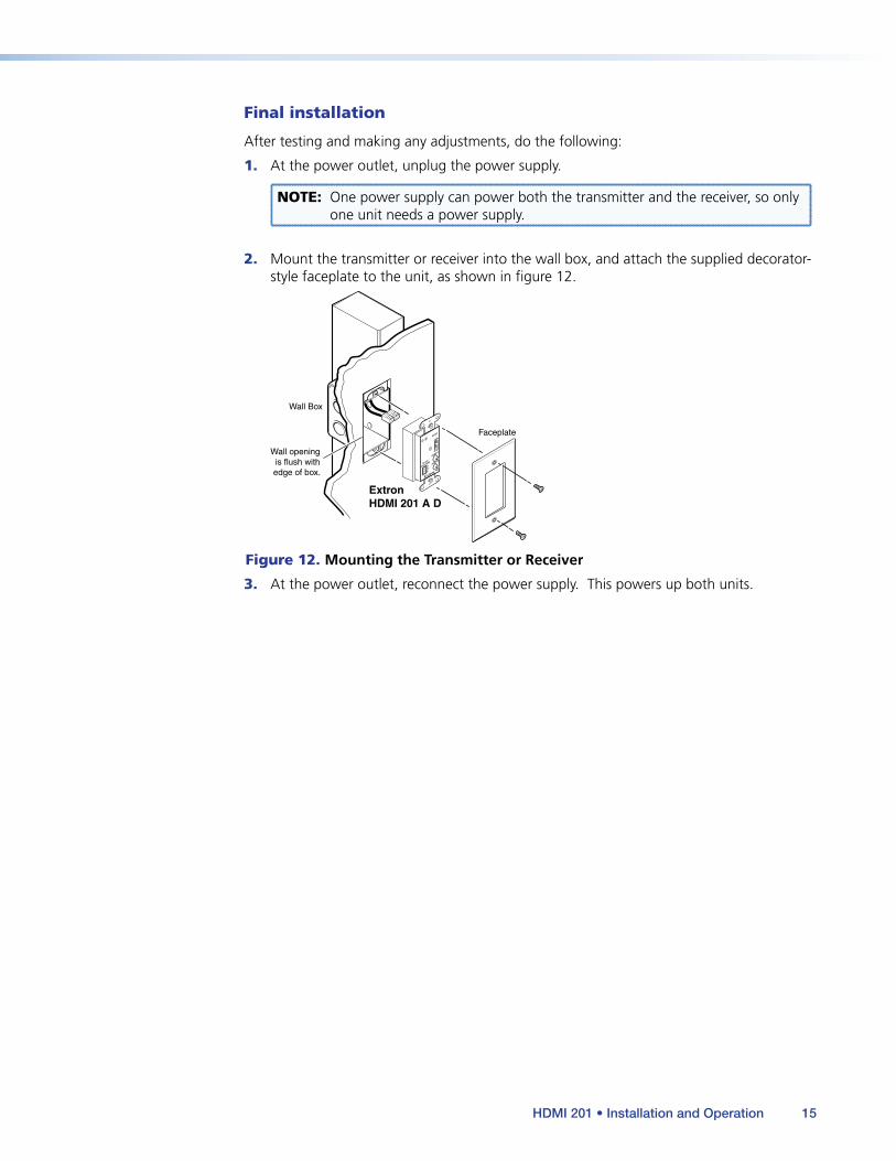
2. Mount the transmitter or receiver into the wall box, and attach the supplied decorator-style faceplate to the unit, as shown in figure 12.
Wall openingis flush withedge of box.
Wall Box
Faceplate
ExtronHDMI 201 A D
INPUT
Tx
Rx
RS-232
PASS THRU
AUDIO-R
HDMI
AUDIO-L
Figure 12. Mounting the Transmitter or Receiver
3. At the power outlet, reconnect the power supply. This powers up both units.
HDMI 201 • Installation and Operation 15

Connections
Transmitter Connections
The wall-mountable transmitter is in an enclosure that can be mounted in UL standard wall boxes with decorator-style face plates. The rack-mountable transmitter is in a quarter rack width enclosure.
Figure 13 shows the front panel of the HDMI 201 A D Tx. Figure 14, on the next page, shows the rear panel of both HDMI 201 Tx models.
HDMI 201 A D Tx Front Panel
INPUT
RS-232PASS THRU
AUDIO-R
HDMI
AUDIO-L
Rx
Tx
2
3
1
Figure 13. HDMI 201 Tx Front Panel Connectors
a HDMI Input connector — Connect an HDMI cable between this port and the HDMI output port of the digital video source. See HDMI connector pin assignments for pin assignments.
b RS-232 connector — Connect a serial communications port to this 3.5 mm, 3-pole captive screw connector for bidirectional RS-232 communication. See RS-232 connector wiring to wire the connector.
NOTE: The RS-232 connector can also transmit one-way modulated infrared (IR) signals. See Modulated IR Pass Through Application.
HDMI 201 • Installation and Operation 16
HDMI 201 Tx Rear Panel
POWER12V 0.4A MAX RS-232
PASS THRU
Tx Rx1 2
HDMI INPUT
HDMI 201 Tx
PO
WE
R12
V
0.4A
MA
X
DO NOT CONNECT
TO LAN
1
2
OUTPUTS
HDMI 201 A D Tx
LA
UD
IOO
UT
PU
TR
4
6
HDMI 201 A D Tx Rear Panel
5
4 1 25
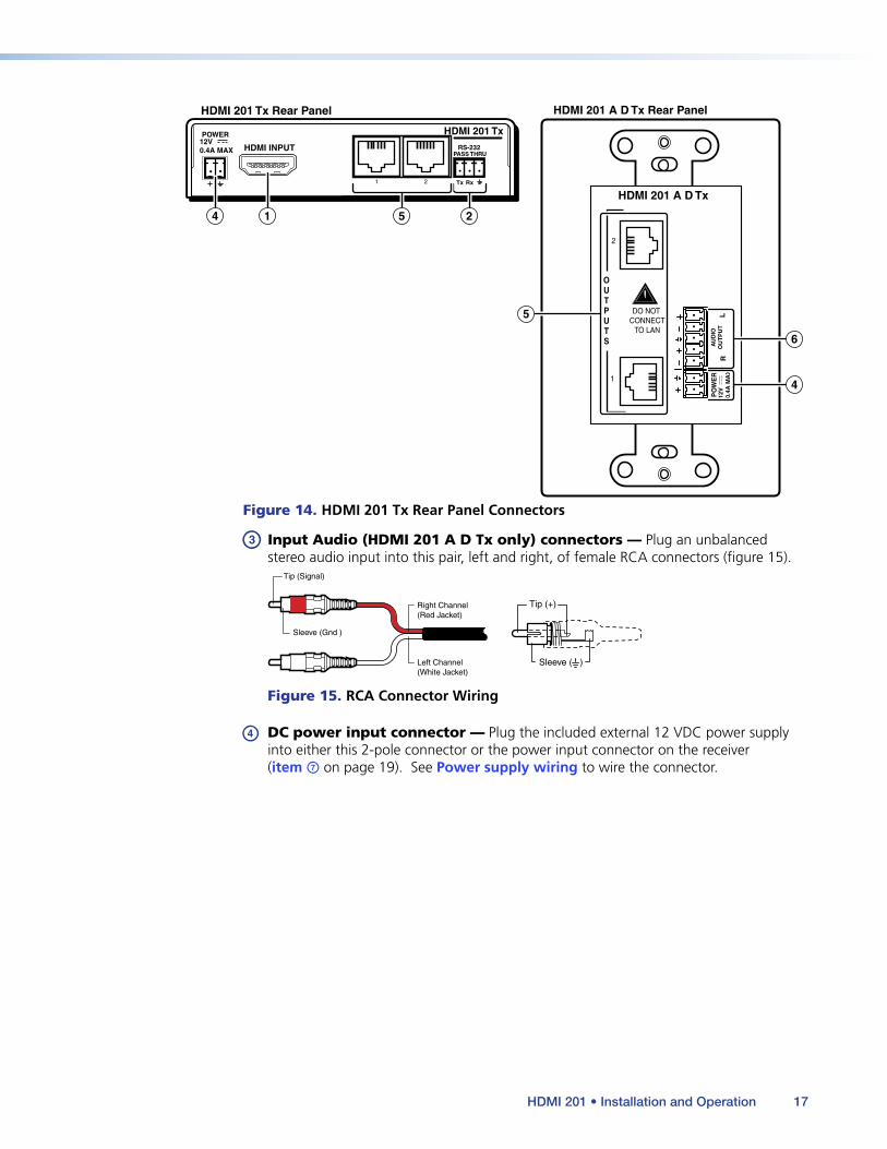
Figure 14. HDMI 201 Tx Rear Panel Connectors
c Input Audio (HDMI 201 A D Tx only) connectors — Plug an unbalanced stereo audio input into this pair, left and right, of female RCA connectors (figure 15).
Sleeve (Gnd )
Tip (+)
Sleeve ( )
Right Channel(Red Jacket)
Left Channel(White Jacket)
Tip (Signal)
Figure 15. RCA Connector Wiring
d DC power input connector — Plug the included external 12 VDC power supply into either this 2-pole connector or the power input connector on the receiver (item g on page 19). See Power supply wiring to wire the connector.
HDMI 201 • Installation and Operation 17
e Transmitter output ports — Connect one end of two separate TP cables to these RJ-45 female connectors on the transmitter.
ATTENTION:
• Do not connect this connector to a computer data or telecommunications network.
• Ne connectez pas ces port à des données informatiques ou à un réseau de télécommunications.
Connect the free ends of the same TP cables from the transmitter to the female Input RJ-45 connectors (item h on page 20) on the receiver.
See TP cable termination to properly wire the RJ-45 connectors.
NOTES: • Extron recommends 28AWG to 24AWG TP cable for the RJ-45 connectors.
• For resolutions of 1600x1200, 1920x1200, and 1080p, Extron strongly recommends DTP26 cable, or equivalent.
• Connect transmitter output 1 to receiver input 1. Connect transmitter output 2 to receiver input 2.
• If necessary, test for proper cable connection (output 1 to input 1, output 2 to input 2) as follows:
1. Plug both TP cables into the powered unit.
2. Momentarily connect either of the cables on the opposite end into the “2” connector on the unpowered unit.
If the Power LED on the unpowered unit is lit, the connection is correct.
If the Power LED on the unpowered unit is not lit, unplug the connector on the unpowered end and connect the other cable to the “2” connector.
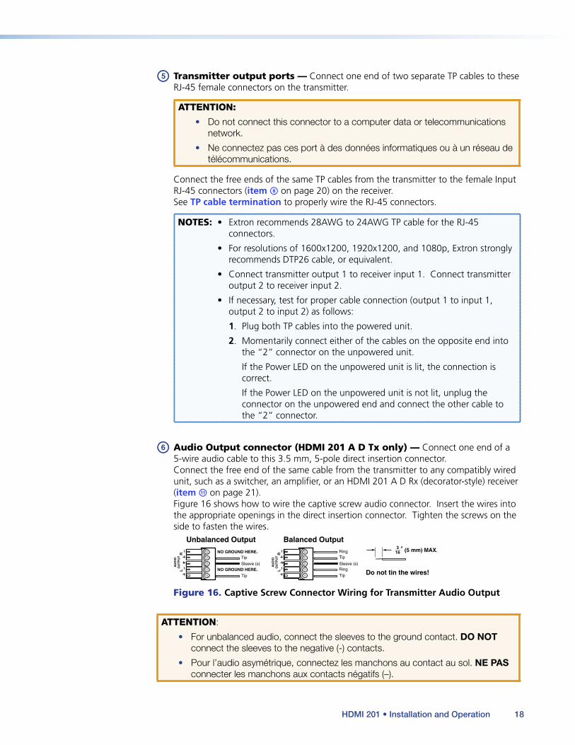
f Audio Output connector (HDMI 201 A D Tx only) — Connect one end of a 5-wire audio cable to this 3.5 mm, 5-pole direct insertion connector.
Connect the free end of the same cable from the transmitter to any compatibly wired unit, such as a switcher, an amplifier, or an HDMI 201 A D Rx (decorator-style) receiver (item k on page 21).
Figure 16 shows how to wire the captive screw audio connector. Insert the wires into the appropriate openings in the direct insertion connector. Tighten the screws on the side to fasten the wires.
Unbalanced Output Balanced Output
Do not tin the wires!L
AU
DIO
OU
TP
UT
R
Tip
Sleeve (s) Sleeve (s)
Tip
NO GROUND HERE.
NO GROUND HERE.
Tip
Tip
Ring
Ring
L
AU
DIO
OU
TP
UT
R
Figure 16. Captive Screw Connector Wiring for Transmitter Audio Output
ATTENTION:
• For unbalanced audio, connect the sleeves to the ground contact. DO NOT connect the sleeves to the negative (-) contacts.
• Pour l’audio asymétrique, connectez les manchons au contact au sol. NE PAS connecter les manchons aux contacts négatifs (–).
HDMI 201 • Installation and Operation 18
Receiver Connections
The rack-mountable receiver is in quarter rack width enclosure. The wall-mountable receiver is in an enclosure that can be mounted in UL standard wall boxes with decorator-style face plates.
Figure 17 shows the rear panel of both HDMI 201 Rx models. Figure 18, on the next page, shows the front panel of the HDMI 201 A D Rx (decorator-style) receiver.
HDMI 201 Rx Rear Panel HDMI 201 A D Rx Rear Panel
POWER12V 0.4A MAX
1 2
HDMI OUTPUT RS-232PASS THRU
Tx Rx
HDMI 201 Rx
PO
WE
R12
V
0.4A
MA
X
DO NOT CONNECT
TO LAN
1
2
INPUTS
HDMI 201 A D Rx
LA
UD
IOIN
PU
TR
7 9 108
7
11
8
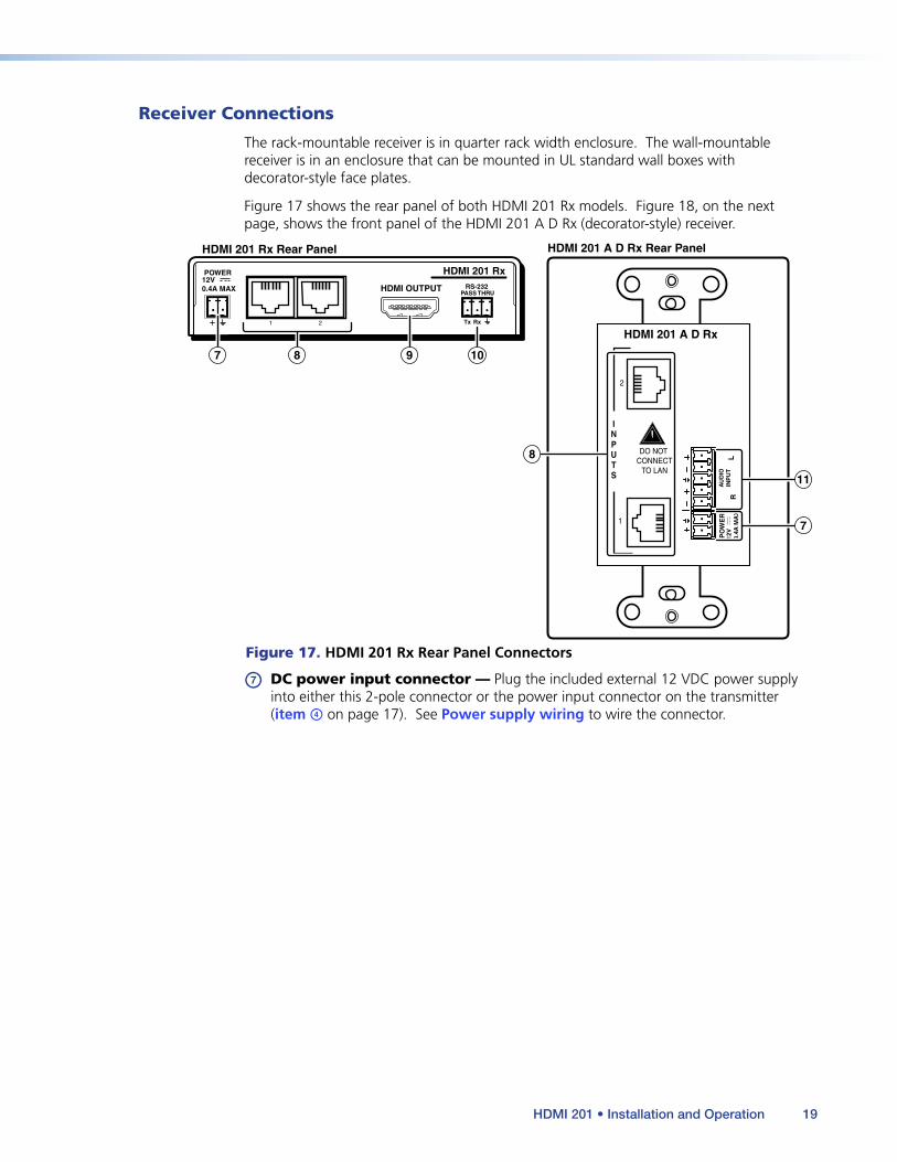
Figure 17. HDMI 201 Rx Rear Panel Connectors
g DC power input connector — Plug the included external 12 VDC power supply into either this 2-pole connector or the power input connector on the transmitter (item d on page 17). See Power supply wiring to wire the connector.
HDMI 201 • Installation and Operation 19
HDMI 201 A D Rx Front Panel
OUTPUT
Rx
Tx
RS-232PASS THRU
AUDIO-R
HDMI
AUDIO-L
10
12
9
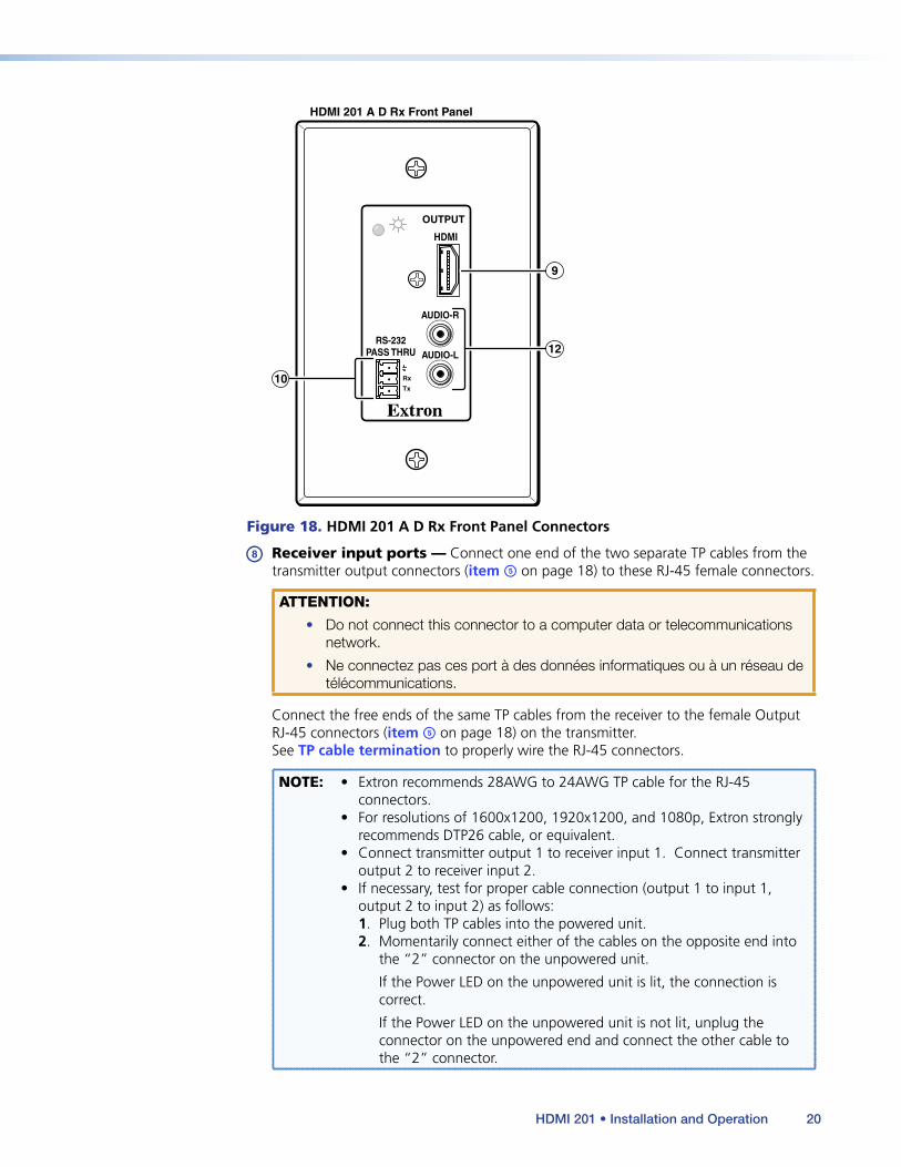
Figure 18. HDMI 201 A D Rx Front Panel Connectors
h Receiver input ports — Connect one end of the two separate TP cables from the transmitter output connectors (item e on page 18) to these RJ-45 female connectors.
ATTENTION:
• Do not connect this connector to a computer data or telecommunications network.
• Ne connectez pas ces port à des données informatiques ou à un réseau de télécommunications.
Connect the free ends of the same TP cables from the receiver to the female Output RJ-45 connectors (item e on page 18) on the transmitter.
See TP cable termination to properly wire the RJ-45 connectors.
NOTE: • Extron recommends 28AWG to 24AWG TP cable for the RJ-45 connectors.
• For resolutions of 1600x1200, 1920x1200, and 1080p, Extron strongly recommends DTP26 cable, or equivalent.
• Connect transmitter output 1 to receiver input 1. Connect transmitter output 2 to receiver input 2.
• If necessary, test for proper cable connection (output 1 to input 1, output 2 to input 2) as follows:1. Plug both TP cables into the powered unit.2. Momentarily connect either of the cables on the opposite end into
the “2” connector on the unpowered unit.
If the Power LED on the unpowered unit is lit, the connection is correct.
If the Power LED on the unpowered unit is not lit, unplug the connector on the unpowered end and connect the other cable to the “2” connector.
HDMI 201 • Installation and Operation 20
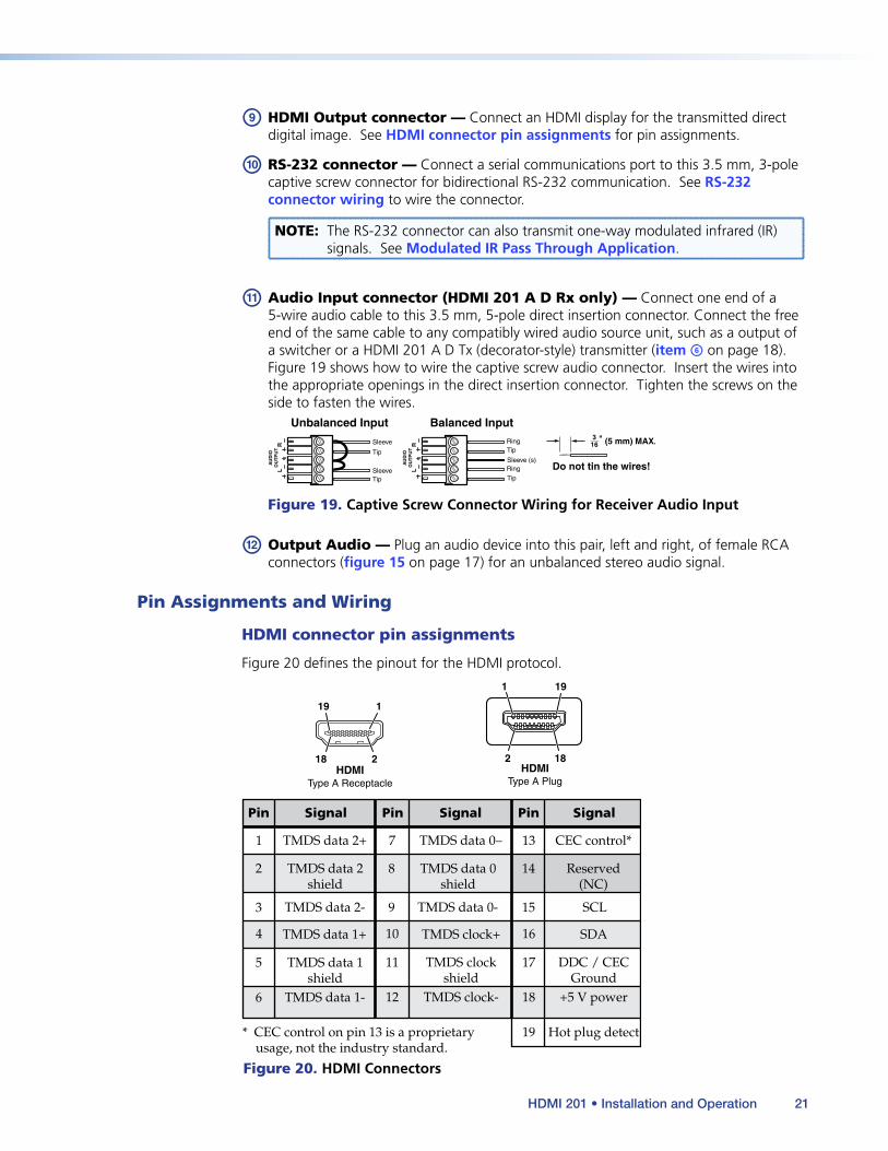
i HDMI Output connector — Connect an HDMI display for the transmitted direct digital image. See HDMI connector pin assignments for pin assignments.
j RS-232 connector — Connect a serial communications port to this 3.5 mm, 3-pole captive screw connector for bidirectional RS-232 communication. See RS-232 connector wiring to wire the connector.
NOTE: The RS-232 connector can also transmit one-way modulated infrared (IR) signals. See Modulated IR Pass Through Application.
k Audio Input connector (HDMI 201 A D Rx only) — Connect one end of a 5-wire audio cable to this 3.5 mm, 5-pole direct insertion connector. Connect the free end of the same cable to any compatibly wired audio source unit, such as a output of a switcher or a HDMI 201 A D Tx (decorator-style) transmitter (item f on page 18).
Figure 19 shows how to wire the captive screw audio connector. Insert the wires into the appropriate openings in the direct insertion connector. Tighten the screws on the side to fasten the wires.
Tip
Sleeve
Sleeve
Tip
Unbalanced Input Balanced Input
Do not tin the wires!Sleeve (s)
Tip
Tip
Ring
Ring
L
AU
DIO
OU
TP
UT
R
L
AU
DIO
OU
TP
UT
R
Figure 19. Captive Screw Connector Wiring for Receiver Audio Input
l Output Audio — Plug an audio device into this pair, left and right, of female RCA connectors (figure 15 on page 17) for an unbalanced stereo audio signal.
Pin Assignments and Wiring
HDMI connector pin assignments
Figure 20 defines the pinout for the HDMI protocol.
Pin Signal
1 TMDS data 2+
TMDS data 2-
TMDS data 0–
TMDS clock- +5 V power
Hot plug detect
CEC control*
Reserved(NC)
TMDS data 1+ TMDS clock+
TMDS clockshield
SDA
DDC / CECGround
TMDS data 2shield
Pin Pin Signal Signal
2
7 13
4 10 16
11 17
12 18
19* CEC control on pin 13 is a proprietary usage, not the industry standard.
14
3 TMDS data 0-
TMDS data 0shield
8
9 SCL15
TMDS data 1-
TMDS data 1shield
5
6
HDMI HDMIType A Receptacle Type A Plug
1
18 2
19
1
182
19
Figure 20. HDMI Connectors
HDMI 201 • Installation and Operation 21

TP cable termination
Figure 21 details the recommended termination of TP cables with RJ-45 connectors in accordance with either the TIA/EIA T 568A or the TIA/EIA T 568B wiring standard.
5
Pin
1
2
3
6
7
8
4
N Terminate both ends of both cables identically, in accordance with either the TIA/EIA T 568A or the TIA/EIA T 568B wiring standard.
Wire color
White-green
Green
White-orange
White-blue
Orange
White-brown
Brown
Blue
Data 0+
Data 0–
Data 1–
ID Clock–
Data 2+
Data 2–
Wire color
White-green
Green
White-orange
White-blue
Orange
White-brown
Brown
SignalTIA/EIA T
568 ATIA/EIA T
568 BRJ-45 #1
ID Clock+
Data 1+Blue
CEC
HPD
RS-232TX
+12 V
RS-232RX
DDC data
Ground
RJ-45 #2
DDC Clk
12345678
InsertTwisted
Pair Wires
Pins: RJ-45Connector
Figure 21. TP Cable Termination
NOTES: • RJ-45 termination with CAT 5, CAT 5e, CAT 6, or DTP26 cable must comply with the TIA/EIA T 568A or TIA/EIA T 568B wiring standard for all connections.
• Extron recommends 28AWG to 24AWG TP cable for the RJ-45 connectors.
• Do not use Extron UTP23SF-4 Enhanced Skew-Free™ A/V UTP cable to link the transmitter and receiver. Skew-free A/V cable was designed for most Extron TP transmitter/receiver applications, but the HDMI 201 Tx/Rx does not work properly with this cable.
• In order to fit in the junction box, the TP cables and RJ-45 connectors should not have a boot installed.
• Connect transmitter output 1 to receiver input 1. Connect transmitter output 2 to receiver input 2.
• If necessary, test for proper cable connection (output 1 to input 1, output 2 to input 2) as follows:
1. Plug both TP cables into the powered unit.
2. Momentarily connect either of the cables on the opposite end into the “2” connector on the unpowered unit.
If the Power LED on the unpowered unit is lit, the connection is correct.
If the Power LED on the unpowered unit is not lit, unplug the connector on the unpowered end and connect the other cable to the “2” connector.
• The transmitter and receiver pair works with unshielded twisted pair (UTP) or shielded twisted pair (STP) cables; but, to ensure FCC Class A and CE compliance, STP cables are required. See Terminating shielded cable.
HDMI 201 • Installation and Operation 22

Terminating shielded cable
The Tx and Rx each include two shielded RJ-45 connectors and a length of self-adhesive shielded tape that you can use to make the STP cables that connect the transmitter and receiver.
NOTES: • The transmitter and receiver pair works with unshielded twisted pair (UTP) or shielded twisted pair (STP) cables; but, to ensure FCC Class A and CE compliance, STP cables are required.
• Extron supplies the connectors and the shielded tape. You must supply the CAT 5, 5e, 6, or DTP26 cable.
Terminate the STP cable as follows:
1. Peel back the cable shielding (figure 22) from the end of the cable the length of the RJ-45 connector body (approximately 7/8 inch [2.2 cm]) and fold it back.
Peel back shield andfold back.
Figure 22. Peeling Back the Cable Shielding
2. Cut away and discard the clear cellophane inner wrapper from the end of the cable back to the folded-over cable shielding.
3. Peel the backing off the self-adhesive shielded aluminum tape and wrap it around the folded-over cable shielding, slightly overlapping the beginning of the tape (figure 23).
Aluminum Tape Wrap tape around folded foil shielding.Slightly overlap.Cut and save the excess tapefor other connectors.
Figure 23. Wrapping the Shielded Tape
4. Cut the unused portion of the shielded tape and retain for shielding other RJ-45 connectors.
5. Feed each individual wire into the appropriate slot of the RJ-45 connector and crimp the cable in the normal manner, folding the tangs at the end of the connector over the shielded tape (figure 24).
Crimped Connector
Figure 24. Crimped RJ-45 Connector
HDMI 201 • Installation and Operation 23
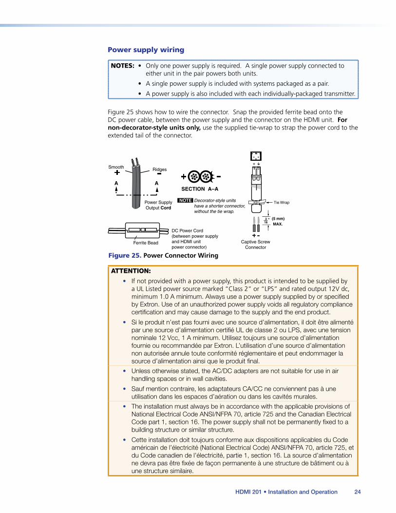
Power supply wiring
NOTES: • Only one power supply is required. A single power supply connected to either unit in the pair powers both units.
• A single power supply is included with systems packaged as a pair.
• A power supply is also included with each individually-packaged transmitter.
Figure 25 shows how to wire the connector. Snap the provided ferrite bead onto the DC power cable, between the power supply and the connector on the HDMI unit. For non-decorator-style units only, use the supplied tie-wrap to strap the power cord to the extended tail of the connector.
Power SupplyOutput Cord
NOTE
Captive ScrewConnector
SECTION A–A
RidgesSmooth
AA
Ferrite Bead
DC Power Cord(between power supplyand HDMI unitpower connector)
Decorator-style unitshave a shorter connector,without the tie wrap.
Tie Wrap
3 5
Figure 25. Power Connector Wiring
ATTENTION:
• If not provided with a power supply, this product is intended to be supplied by a UL Listed power source marked “Class 2” or “LPS” and rated output 12V dc, minimum 1.0 A minimum. Always use a power supply supplied by or specified by Extron. Use of an unauthorized power supply voids all regulatory compliance certification and may cause damage to the supply and the end product.
• Si le produit n’est pas fourni avec une source d’alimentation, il doit être alimenté par une source d’alimentation certifié UL de classe 2 ou LPS, avec une tension nominale 12 Vcc, 1 A minimum. Utilisez toujours une source d’alimentation fournie ou recommandée par Extron. L’utilisation d’une source d’alimentation non autorisée annule toute conformité réglementaire et peut endommager la source d’alimentation ainsi que le produit final.
• Unless otherwise stated, the AC/DC adapters are not suitable for use in air handling spaces or in wall cavities.
• Sauf mention contraire, les adaptateurs CA/CC ne conviennent pas à une utilisation dans les espaces d’aération ou dans les cavités murales.
• The installation must always be in accordance with the applicable provisions of National Electrical Code ANSI/NFPA 70, article 725 and the Canadian Electrical Code part 1, section 16. The power supply shall not be permanently fixed to a building structure or similar structure.
• Cette installation doit toujours conforme aux dispositions applicables du Code américain de l’électricité (National Electrical Code) ANSI/NFPA 70, article 725, et du Code canadien de l’électricité, partie 1, section 16. La source d’alimentation ne devra pas être fixée de façon permanente à une structure de bâtiment ou à une structure similaire.
HDMI 201 • Installation and Operation 24

ATTENTION:
• Power supply voltage polarity is critical. Incorrect voltage polarity can damage the power supply and the unit. The ridges on the side of the cord (see figure 5 on the previous page) identify the power cord negative lead.
• La polarité de la source d’alimentation est primordiale. Une polarité incorrecte pourrait endommager la source d’alimentation et l’unité. Les stries sur le côté du cordon (voir l’illustration 5 sur la page 10) permettent de repérer le pôle négatif du cordon d’alimentation.
To verify the polarity before connection, plug in the power supply with no load and check the output with a voltmeter.
CAUTION:
ATTENTION :
• The wires must be kept separate while the power supply is plugged in. Remove power before wiring.
• Les deux cordons d’alimentation doivent être maintenus séparés lorsque la source d’alimentation est branchée. Coupez l’alimentation avant d’effectuer un raccordement.
• The length of exposed wires is important. The ideal length is 3/16 inch (5 mm).
• Any longer and the exposed wires may touch, causing a short circuit between them.
• Any shorter and the wires can be easily pulled out even if tightly fastened by the captive screws.
• La longueur des câbles exposés est importante. La longueur idéale est de 5 mm (3/16 inches).
• S’ils sont trop longs, les câbles exposés pourraient se toucher et provoquer un court-circuit.
• S’ils sont trop courts, ils peuvent être tirés facilement, même s’ils sont correctement serrés par les borniers à vis.
• Do not tin the power supply leads before installing them in the connector. Tinned wires are not as secure in the connector and could be pulled out.
• Ne pas étamer les conducteurs avant de les insérer dans le connecteur. Les câbles étamés ne sont pas aussi bien fixés dans le connecteur et pourraient être retirés.
HDMI 201 • Installation and Operation 25

RS-232 connector wiring
Figure 26 shows how to wire the RS-232 connector for all units.
Ground
Receive pin on connected unitTransmit pin on connected unit
Connected RS-232Device Pins
Tx/RxPins
Rx
Tx
Figure 26. RS-232 Connector Wiring
CAUTION: The length of the exposed (stripped) copper wires is important. The ideal length is 3/16 inch (5 mm). Longer bare wires can short together. Shorter wires are not as secure in the connectors and could be pulled out.
NOTES: • Do not tin the power supply leads before installing them in the direct insertion connector. Tinned wires are not as secure in the connectors and could be pulled out.
• The RS-232 connector can also transmit one-way modulated infrared (IR) signals. See Modulated IR Pass Through Application.
OperationFigure 27 shows the power indicator on all models.
NOTE: Two units are shown. All transmitter and receiver models have power indicators in the locations shown.
HDMI 201
INPUT
Rx
Tx
RS-232PASS THRU
AUDIO-R
HDMI
AUDIO-L
Power
HDMI 201 Tx and HDMI 201 Rx Front Panel HDMI 201 A D Tx and HDMI 201 A D Rx Front Panel
Power
Figure 27. Front Panel Indicators
HDMI 201 • Installation and Operation 26

Transmitter Power Indicator Power LED —
HDMI 201 Tx (non-decorator-style) — This front panel LED lights green to indicate that the unit is receiving power:
HDMI 201 A D Tx (decorator-style) — This two-color front panel LED lights to indicate signal and power status as follows:
Amber — The unit is receiving power but not an HDMI input.
Green — The unit is receiving power and a signal is present on the HDMI input.
Receiver Power Indicator Power LED —
HDMI 201 Rx (non-decorator-style) — This front panel LED lights green to indicate that the unit is receiving power:
HDMI 201 A D Rx (decorator-style) — This two-color front panel LED lights to indicate signal and power status as follows:
Amber — The unit is receiving power but not a TP input.
Green — The unit is receiving power and a signal is present on the TP input.
System Operation
After the transmitter, the receiver, and their connected devices are powered up, the system is fully operational. If any problems are encountered, ensure all cables are routed and connected properly.
NOTE: Ensure that the video source and display selected for the DDC are properly connected to the transmitter/receiver pair, and that the transmitter, the receiver, and the display have power applied before power is applied to the video source. If all other devices are not turned on before the video source, the image may not appear.
Technical Points for Digital Video and Content Protection Encryption• Digital Visual Interface (DVI) is a digital video format that was created by the
computer industry in 1999.
• High Definition Multimedia Interface (HDMI®) is a multimedia format that was created by the consumer video industry in 2003.
о The HDMI format is built onto the DVI format, adding digital audio and control while reducing the size of the connector.
о The HDMI format is likely to replace the DVI format in the near future.
о With passive adapters, the HDMI format is backward compatible with the DVI format.
• With Extron adapters, cables, or both, the HDMI 201 fully supports either format, regardless of the connector type on the video source and display. See Template Dimensions for part numbers.
HDMI 201 • Installation and Operation 27

• High-bandwidth Digital Content Protection (HDCP) is an encryption method that protects copyrighted digital entertainment material that uses DVI video.
о HDCP is generated by video player hardware, enabled by the video content.
о The HDCP key is transmitted with the Display Data Channel (DDC).
о The DDC signal line was designed for the low data rate of the DDC; the HDCP key rate is much higher.
• Without active buffering, an HDCP key signal can travel only a short distance. The display may properly receive the digital video signal, but not the HDCP key. Without the key, the display cannot decrypt the video signal. Symptoms of undecrypted video may include a flashing black or blue screen or “snow”.
• With active buffering, an HDCP key signal can travel as far as other signals to ensure proper decryption.
• The HDMI 201 actively buffers the HDCP key.
TroubleshootingHDMI signals run at a very high frequency and are especially susceptible to bad video connections, too many adapters, or cables that are too long. To avoid the loss of an image or introduction of image jitter, follow these guidelines:
• The HDMI cable on the input to the transmitter or the output of the receiver should not exceed 10 feet (3 m).
• Use only cable designed for HDMI signals.
• Limit or avoid the use of adapters or patch points between the transmitter and receiver.
• If the display exhibits a flashing black or blue screen, snow, or other distortion, a non-HDCP compliant display may be receiving an HDCP-encrypted signal.
Check for an HDCP problem by ejecting the DVD from the player. If the display distortion stops and the DVD menu or screen saver image is clear, the problem is HDCP-related.
• If image artifacts are present, the TP cable may be the cause. Extron recommends DTP26 cable.
• The HDMI 201 works as described in point-to-point applications. Do not use any additional adapters, patch panels, or couplers with the input HDMI cables, output HDMI cables, and twisted pair cables. Additional links in the signal chain can result in the reduction of signal integrity and overall cable length performance.
HDMI 201 • Installation and Operation 28
Application Examples
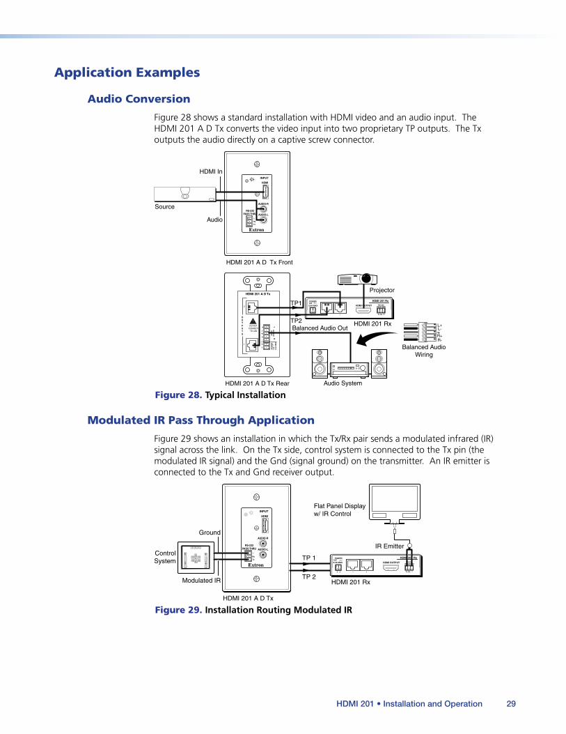
Audio Conversion
Figure 28 shows a standard installation with HDMI video and an audio input. The HDMI 201 A D Tx converts the video input into two proprietary TP outputs. The Tx outputs the audio directly on a captive screw connector.
POWER12V 0.4A MAX
1 2
HDMI OUTPUT RS-232PASS THRU
Tx Rx
HDMI 201 Rx
INPUT
RS-232PASS THRU
AUDIO-R
HDMI
AUDIO-L
PO
WE
R12
V
0.4A
MA
X
DO NOT CONNECT
TO LAN
1
2
OUTPUTS
HDMI 201 A D Tx
LA
UD
IOO
UT
PU
TR
Rx
Tx
HDMI In
Source
Audio
TP1
TP2Balanced Audio Out
Balanced AudioWiring
Audio System
HDMI 201 A D Tx Front
HDMI 201 A D Tx Rear
HDMI 201 Rx
Projector
R+R-
L+L-
Figure 28. Typical Installation
Modulated IR Pass Through Application
Figure 29 shows an installation in which the Tx/Rx pair sends a modulated infrared (IR) signal across the link. On the Tx side, control system is connected to the Tx pin (the modulated IR signal) and the Gnd (signal ground) on the transmitter. An IR emitter is connected to the Tx and Gnd receiver output.
INPUT
RS-232PASS THRU
AUDIO-R
HDMI
AUDIO-L
Rx
Tx TP 1
Ground
ControlSystem
Modulated IR TP 2HDMI 201 Rx
HDMI 201 A D Tx
POWER12V 0.4A MAX
1 2
HDMI OUTPUT RS-232PASS THRU
Tx Rx
HDMI 201 Rx
IR Emitter
Flat Panel Displayw/ IR Control
Figure 29. Installation Routing Modulated IR
HDMI 201 • Installation and Operation 29
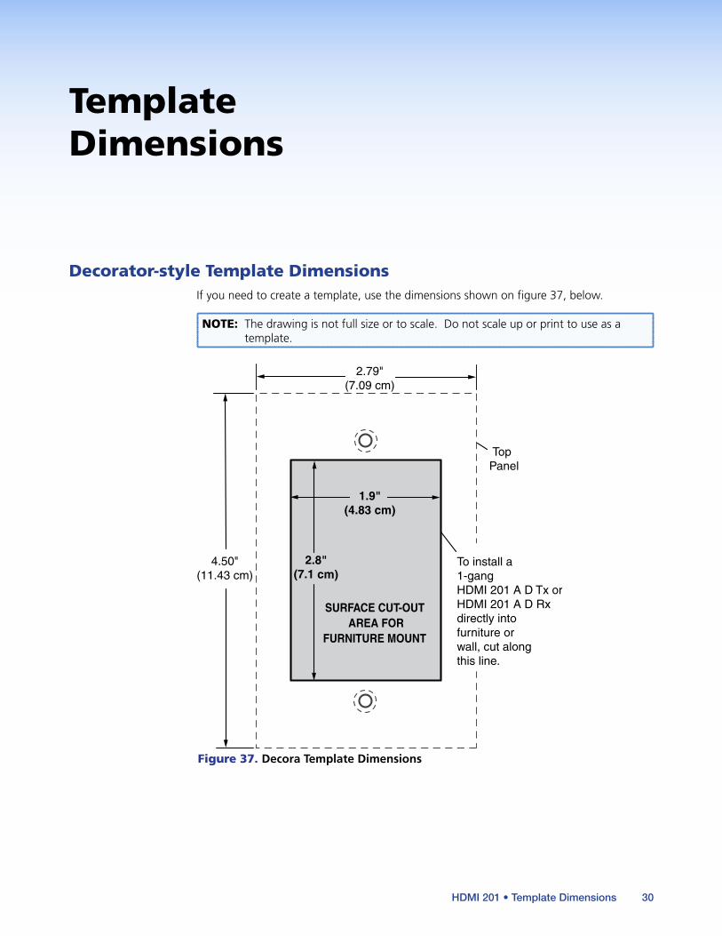
Template Dimensions
Decorator-style Template DimensionsIf you need to create a template, use the dimensions shown on figure 37, below.
NOTE: The drawing is not full size or to scale. Do not scale up or print to use as a template.
4.50" (11.43 cm)
Top Panel
SURFACE CUT-OUT AREA FOR
FURNITURE MOUNT
2.79" (7.09 cm)
1.9" (4.83 cm)
2.8" (7.1 cm)
To install a1-gang HDMI 201 A D Tx orHDMI 201 A D Rx directly intofurniture or wall, cut along this line.
Figure 37. Decora Template Dimensions
HDMI 201 • Template Dimensions 30
Extron Headquarters+1.800.633.9876 (Inside USA/Canada Only)
Extron USA - West Extron USA - East +1.714.491.1500 +1.919.850.1000 +1.714.491.1517 FAX +1.919.850.1001 FAX
Extron Europe+800.3987.6673 (Inside Europe Only)
+31.33.453.4040 +31.33.453.4050 FAX
Extron Asia+65.6383.4400+65.6383.4664 FAX
Extron Japan+81.3.3511.7655+81.3.3511.7656 FAX
Extron China+86.21.3760.1568 +86.21.3760.1566 FAX
Extron Middle East+971.4.299.1800+971.4.299.1880 FAX
Extron Australia+61.8.8113.6800+61.8.8351.2511 FAX
Extron India1800.3070.3777 (Inside India Only)
+91.80.3055.3777 +91.80.3055.3737 FAX
© 2019 Extron Electronics All rights reserved. www.extron.com
Contact Information
Extron Warranty
Extron Electronics warrants this product against defects in materials and workmanship for a period of three years from the date of purchase. In the event of malfunction during the warranty period attributable directly to faulty workmanship and/or materials, Extron Electronics will, at its option, repair or replace said products or components, to whatever extent it shall deem necessary to restore said product to proper operating condition, provided that it is returned within the warranty period, with proof of purchase and description of malfunction to:
USA, Canada, South America, and Central America:Extron Electronics 1230 South Lewis Street Anaheim, CA 92805 U.S.A.
Japan:Extron Electronics, Japan Kyodo Building, 16 Ichibancho Chiyoda-ku, Tokyo 102-0082 Japan
Europe and Africa:Extron Europe Hanzeboulevard 10 3825 PH Amersfoort The Netherlands
China:Extron China 686 Ronghua Road Songjiang District Shanghai 201611 China
Asia:Extron Asia Pte Ltd 135 Joo Seng Road, #04-01 PM Industrial Bldg. Singapore 368363 Singapore
Middle East:Extron Middle East Dubai Airport Free Zone F13, PO Box 293666 United Arab Emirates, Dubai
This Limited Warranty does not apply if the fault has been caused by misuse, improper handling care, electrical or mechanical abuse, abnormal operating conditions, or if modifications were made to the product that were not authorized by Extron.
NOTE: If a product is defective, please call Extron and ask for an Application Engineer to receive an RA (Return Authorization) number. This will begin the repair process. USA: 714.491.1500 or 800.633.9876 Europe: 31.33.453.4040 Asia: 65.6383.4400 Japan: 81.3.3511.7655
Units must be returned insured, with shipping charges prepaid. If not insured, you assume the risk of loss or damage during shipment. Returned units must include the serial number and a description of the problem, as well as the name of the person to contact in case there are any questions.
Extron Electronics makes no further warranties either expressed or implied with respect to the product and its quality, performance, merchantability, or fitness for any particular use. In no event will Extron Electronics be liable for direct, indirect, or consequential damages resulting from any defect in this product even if Extron Electronics has been advised of such damage.
Please note that laws vary from state to state and country to country, and that some provisions of this warranty may not apply to you.