hdormational ---- - --- --- ----~ and decision processes...
TRANSCRIPT

hdormational and Decision ---- _ - ---_--- _ ----~
Processes for Flexible Manukdurina Svsfems Abhijit Chaudhury, University of Massachusetts at Boston Sukumar Rathnam, University of Texas at Austin
A MERICAN MANUFACTURERS must use computers to automate produc- tion if the US is to compete successfully in an international economy. Researchers around the world spent about $40 billion in 1990 trying to solve planning and control problems in industrial automation, with about $20 billion of that going to four techniques: computerized manufacturing systems. computer numerically controlled (CNC) systems, robots, and flexible manu- facturing systems.’ Much of the money invested in these technologies was spent on developing the most crucial part of the system: the control software.
WE DESCRlBE ZNFORMATZON AND DECISZON PROCESSES IN
TERMS OF THREE FUNDAMENTAL CONCEPTS: TASK
DECOMPOSITION, ALLOCATION, AND UPDATING. OUR OBJECT-
ORIENTED, LOGIC-PROGRAMMING PARADIGM MAPS THESE
CONCEPTS TO COMPUTATIONAL ELEMENTS, PROVlDlNG THE
BASlS FOR A POWERFUL PROGRAMMING ENVIRONMENT.
We propose using a formal method to develop control software for flexible man- ufacturing systems. Formal methods are math-based techniques that make it easier to describe software specifications forcom- plex systems and to support software ver- ification and testing.’ They help to reveal ambiguities, expose errors, communicate complex ideas, and prove the correctness of system properties. They are especially important when there must be a clear bound- ary between specification and implemen- tation. Formal methods are being used in major software projects such as IBM’s CICS, Praxis Systems’ Case project, and the Portable Common Tools Environment.
gramming environment.” Our approach tries to minimize the effort needed to transform the manufacturer’s problem description (with its parts, machines, and objects)‘into the programmer’s solution plan (with its programs and data). The representation scheme facilitates abstract and high-level descriptions as well as automated reason- ing6 by using primitives representing the domain elements (lathes, engines, and so on) and their interrelationships (for exam- ple, a manufacturing schedule). Our objec- tive in this article is not to elaborate on tools for simulating manufacturing pro- cesses, but rather to describe the program- ming language constructs that facilitate software modeling and the development of decision-making algorithms in a flexible manufacturing systems.
Without effective software operating on appropriate information and knowledge. such techniques cannot ensure a productive and profitable manufacturing system. Sev- eral flexible manufacturing systems are not being used to their potential because even experienced operators find it difficult to run them efficiently.’ However, while re- searchers have studied the design of impor- tant subsystems, such as planning and sched- uling models, they have not directed much effort toward investigating the control soft- ware’s total structure. Some researchers have tried to apply expert systems to these problems. but such systems cannot encom- pass theentiremanufacturingenvironment.’
Our formal method is based on the Se- mantic Unification and Logic (Semlog) environment, a typed object-oriented pro-
DECEMBER 1992 0885/9000/92/l ?OO-0053 $3.00 0 I’)‘)2 IEEE 53

Planning and control in en FMS
the processors can make decisions over a wide range of informational and decision tasks without intervention either from peo-
tools at the lowest level are responsible for activities such as matching, measuring, handling, transporting, and storing. Each must be able to
l exchange messages with the worksta- tion and the cell controller,
l allow access to machine and controller
A flexible manufacturing system, or FMS, ple or from higher levels of the system..The is a flexible collection of communicating data and knowledge bases are also distrib- groups of modular, automated material- uted, so that each processor has its own handling devices and numerically con- memory. At any instant, the total informa- trolled, interchangeable machine tools, all tion base of the system is partitioned among connected by flexible communication links the processors’ individual databases. An
states,
and material-handling systems and inte- intermodule communication system sends grated by a hierarchical network of com- messages for instructions, control, and da- puters. These devices and tools can simul- tabase updating. Processors coordinate taneously process medium-sized volumes 1 activities by exchanging messages. Each Process control information lies at this of various part types. FMSs have been used lowest level in the hierarchy, where deci-
l receive input from sensors, and l send output signals to motors, solenoids,
valves, and other devices.
to improve quality, productivity, use of capital, and responsiveness, and to reduce material handling, labor costs, and inven- tory.’
sion making must adapt to the environ- ment. A controller should be able to cope
A FLEXIBLE with contingencies, including occasional failures from such causes as faulty parts, broken tools, and robot drift. An intelligent and autonomous controller must exhibit rudimentary abilities in error detection and recovery.
Planning at this level involves the sched- uling of individual operations, such as moving, gripping, measuring, and match- ing. The time horizon is seconds or hours, and the processing is done in the FMS computer.
An FMS can have flexibility along sev- eral dimensions:8
l The machine: making the changes need- ed to produce a given set of part types.
l The process: producing a given set of part types, each possibly using different materials, in several ways.
l The product: producing a new set of products economically and quickly.
l Routing: handling breakdowns while con- tinuing to produce a given set of parts.
l Volume: operating profitably at differ- ent production volumes.
l Expansion: building a system in mod- ules and expanding it as needed.
l Operation: interchanging the order of operations for each part type.
l Production: producing a wide universe of part types.
Such a categorization is important to de- signing a representational and reasoning scheme that exploits an FMS’s intrinsic capabilities.
An FMS is an adaptive, dynamic system in which a wide variety ofjobs are contin- uously and randomly introduced. These jobs must be broken down into operations, which then have to be scheduled on various machines. Completedjobs must be removed from the system with minimal, if any, hu- man intervention.
The computers in an FMS carry out different levels of planning and control using heterogeneous, logically integrated, intelligent, autonomous, and spatially dis- tributed processors that share a common goal. Many hardware and software proces- sors are distributed over several distinct hierarchical levels. When left on their own,
k!ANUFACTURlNG SYSTEM IS
AN ADAPTNE, DYNAMIC
SYSTEM IN WHICH A WIDE
VARIETY OF JOBS ARE
CONTINUOUSLY AND
RANDOMLY INTRODUCED.
processor responds deterministically to a well-defined set of messages and can send messages to other processors in order to handle its own incoming messages.
Hierarchy is a natural way (and often the only way9) to control large, complex sys- tems. (This view is not universally held. For example, Rana and Taneja”‘claim that hierarchical approaches cannot deal with the combinatorial explosion of complexity presented by very large systems, they are inflexible and difficult to expand, and they introduce coordination problems.)1 The FMS decision-making process spans acon- trol hierarchy with five levels: the equip- ment (tool), the workstation, the cell, the shop, and the facility.’ t
The system decomposes the goals of the higher levels into commands that are exe- cuted by the lower levels. Feedback from lower levels is passed back to the higher levels, but at a decreasing rate (since this information is abstracted into more com- plex constructs). At the upper levels the FMS makes decisions that will apply over a long time, but this “time horizon” pro- gressively reduces down the levels.
Individual machines and robots. The The shop. This level manages tasks and
Workstations. At the workstation level, the system manages various manufactur- ing operations (setup, equipment tasking, and takedown) and resolves contingencies and conflicts. This level typically includes machines for milling, inspection, and ma- terials handling. The time horizon is min- utes or hours, and processing is done in the FMS computer.
Cells. A manufacturing cell is a group of machine tools and associated material- handling equipment that is managed by a supervisory mainframe or FMS computer, called the cell host. Cells behave as inde- pendent units and need to be integrated to form an FMS. They constitute the middle level, and their principle decision-making function is to coordinate and manage re- sources. Toward this end, the cell host schedules the flow ofjobs in thecell, main- tains a database about pending operations, executes the software for gracefully de- grading the system in the event of failure, and instructs the individual elements as to the tasks each must perform. The time horizon at this level is hours or weeks.
54 IEEE EXPERT

Table 1. Decision-making objects in the FM environment.
Object
Facility
Inputs
Demand scenario (forecasts)
Processing output
Aggregate production Master production planning and differentiation schedule into master production schedule
Shop Planned order Detailed scheduling Detailed schedule release, routing and process plans
Cell controller Schedule, routing, Loading and unloading Material transfer and process plans instructions, materials
transfer instructions
Workstation Tool setups Tool movement plans Tool tasking
Machine tool Individual tool Tool movements Tool movement, movement schedule feedback processing
allocates resources. The decision and con- trol functions exercised by the shop-level supervisory system are similar to those of a cell, but it also dispatches material-han- dling equipment, monitors cell conditions, and collects data. The time horizon is weeks or months, and processing is done in the mainframe.
Much operations research modeling has been concerned with scheduling and se- quencing issues at the shop level; few, if any, models have been suggested for plan- ning and control at other levels. However, researchers have suggested tools based on petri nets for modeling cell-level interac- tion and for designing a shop-level operat- ing and control system.
The facility. As the highest level in the FMS hierarchy, the facility deals primarily with information management, manufac- turing engineering, and production man- agement. It handles the premanufacturing phase of planning, including material re- quirements planning, master production scheduling, and batching. These plantwide functions typically set the overall goals and targets for the long term. The time horizon at this level is months or years. Processing is done on the mainframe.
Generic planning and control func- tions. Each level of the hierarchy is associ- ated with an object that encapsulates the planning and control functions at that level (see Table I). These functions fall into three generic categories:
l Task decornpmirion. The facility-level task of manufacturing an engine can be split at the shop levelinto the tasks of casting, machining, and assembling. At the cell level, the tasks are further bro- ken down into such tasks as drilling, boring, and finishing. Finally, the task description at the individual machine or robot level might include loading, mov- ing, and gripping. Each level has its own set of task symbols that act as a language alphabet for that level. To support task decomposition in an FMS control pro- gram, we need program language con- structs (described later) that facilitate hierarchical data and program definition schemes, as well as primitives for coor- dination.
l Task c~llocurion. An FMS must assign jobs to specific machines or cells. Dy-
.
namic allocation can be very efficient but it is hard to program, especially at the facility and shop levels, because changing contingencies are an intrinsic
supports the highly distributed, complex, and layered nature of FMS information sharing and decision making.
part of the environment, and a great deal of skill is required to identify and elim- Knowledge representation inate errors.” In task allocation, the key requirements is to balance the workload. This mini- mizes the differences in time required All three types of FMS planning and for jobs assigned to different units, and control activities-task decomposition, ensures that all the work for each batch allocation, and updating-have a common is in fact assigned to some machine. To 1 thread: They are completely controlled by allocate tasks, FMS control programs computer programs Product and process need to support incremental specifica- specifications exist as computational pro- tion and the encapsulation of data and cedures that are fed into these programs. programs. Stored specifications enable factories to Tusk updnring. The FMS must maintain produce identical parts on different ma- a database of pending and completed chines in different places. These specifica- tasks. Thus, when a robot has finished 1 tions must anticipate every possible con- cutting a gear, all the parent manufactur- tingency and solve every potential problem ing cells must be notified that the robot with the product and the process. Thus, the is free and can begin the next allocated basic conceptual approach to designing task. Task updating must be robust to 1 FMS control systems must be to support maintain the consistency of the underly- ~ the distributed, multilayer, and intercon- ing database. For example, a robot can- netted nature of FMS decisional and infor- not be declared free unless the job that mational processes with flexible, easily has been scheduled on it has been com- maintainable, and modular software. pleted. To support task updating in a Suri and Whitney propose using deci- dynamic manufacturing environment, the sion support systems and knowledge-based FMS must have an adaptivecontrol strat- systems to design FMS control software.’ egy based on the exchange of informa- Knowledge-based systems differ from usual tion and messages. software systems in that they explicitly
encode domain knowledge. Their linguis- The information flow in an FMS not tic and procedural characteristics are also
only coordinates conversion steps (the steps important: their power to express concepts, that change raw materials into finsihed and their ability to manipulate and reason goods) but also provides the feedback nec- with such knowledge. essary for improvements. Thus the control Effective representation ofdomain-spe- software must be based on a model that cific knowledge is a critical step in build-
DECEMBER 1992 55
I language/ lfrogrammingj
\ / Sem’og \ J Typing
Figure I. The knowledge representation scheme in Semlog.
ing successful knowledge-based systems. When we examine the domain-specific rep- resentational and computational aspects of a typical FMS control system, we find new representational needs beyond the current capabilities offered by multiparadigm-based systems such as the Knowledge Engineer- ing Environment and the Lisp Object-Ori- ented Programming System. An FMS meth- odology must support a variety of requirements under uniform semantics: It must distribute the representation of pro- cedural knowledge among various entities in a taxonomic hierarchy, and support the inheritance of this knowledge. It must also represent changes in dynamic systems us- ing a formal system with well-defined se- mantics, such as lambda calculus or first- order logic. In short. the knowledge representation framework should allow a world view in which the system’s func- tional relationships can be described in the same way they are perceived by program- mers and manufacturing experts. The rep- resentational methodology should support procedural, constraint. spatial, and tempo- ral knowledge.
To formally specify a conceptual de- scription of the decision model. we must translate the model into the paradigms and constructs of programming languages: ob- jects, types. and functions (see Figure I). Thus. to effectively model an FMS control system, a knowledge-based system must
l provide primitives for easy and natu- ral modeling of domain objects, and sup- port multiple inheritance through a lat- tice structure of classes and types; l be strongly typed to allow static type checking. which improves softwarereli- ability:
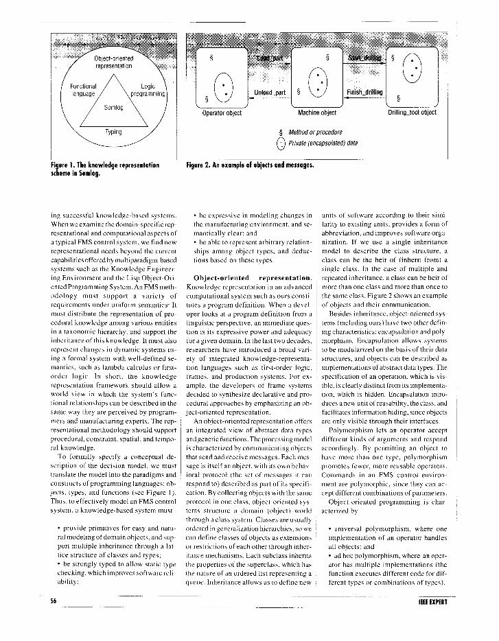
Operator object Machine object
5 Method or procedure
0 -. Private (encapsulated) data
Drilling-tool object
Figure 2. An example of objects and messages.
l be expressive in modeling changes in units of software according to their simi- the manufacturing environment, and se- larity to existing units, provides a form of mantically clear; and abbreviation, and improves software orga- l be able to represent arbitrary relation- nization. If we use a single inheritance ships among object types, and deduc- model to describe the class structure, a tions based on these types. class can be the heir of (inherit from) a
single class. In the case of multiple and Object-oriented representation. repeated inheritance, a class can be heir of
Knowledge representation in an advanced ~ more than one class and more than once to computational system such as ours consti- , the same class. Figure 2 shows an example tutes a program definition. When a devel- ~ of objects and their communication. oper looks at a program definition from a ~ Besides inheritance, object-oriented sys- linguistic perspective, an immediate ques- ~ terns (including ours) have two other defin- tion is its expressive power and adequacy ing characteristics: encapsulation and poly- for a given domain. In the last two decades, ~ morphism. Encapsulation allows systems researchers have introduced a broad vari- ~ to be modularized on the basis of their data ety of integrated knowledge-representa- I structures, and objects can be described as tion languages such as first-order logic, ~ implementations of abstract data types. The frames, and production systems. For ex- specification of an operation, which is vis- ample, the developers of frame systems ible, is clearly distinct from its implementa- decided to synthesize declarative and pro- tion, which is hidden. Encapsulation intro- cedural approaches by emphasizing an ob- duces a new unit of reusability, the class, and ject-oriented representation. facilitates information hiding, since objects
An object-orientedrepresentation offers are only visible through their interfaces. an integrated view of abstract data types Polymorphism lets an operator accept andgeneric functions. The processing model ~ different kinds of arguments and respond is characterized by communicating objects ~ accordingly. By permitting an object to that send and receive messages. Each mes- have more than one type, polymorphism sage is itself an object, with its own behav- ~ promotes fewer, more reusable operators. ioral protocol (the set of messages it can Commands in an FMS control environ- respond to) described as part of its specifi- ment are polymorphic, since they can ac- cation. By collecting objects with the same cept different combinations of parameters. protocol in one class, object-oriented sys- Object-oriented programming is char- terns structure a domain (object) world acterized by through a class system. Classes are usually ordered in generalization hierarchies, so we ~ l universal polymorphism, where one can define classes of objects as extensions implementation of an operator handles or restrictions of each other through inher- all objects; and itance mechanisms. Each subclass inherits l ad hoc polymorphism, where an oper- the properties of the superclass. which has ator has multiple implementations (the the nature of an ordered list representing a function executes different code for dif- queue. Inheritance allows us to define new ferent types or combinations of types).
56 IEEE EXPERT

Universal polymorphism can be either para- metric or inclusive. In parametric polymor- phism, a function has a type parameter that determines the argument type for each appli- cation of that function. In inclusive polymor- phism, an object can belong to many differ- ent classes through the use of subtyping.
We can model an engine-manufacturing plant using objects such as engines, facili- ties, processes, and inventories (see Figure 3). The class of engines leads to such sub- classes as marine engines, automobile en- gines. and truck engines. Each engine can be subdivided further into subclasses, in- cluding engine blocks and crankshafts. We can also describe an engine with attributes such as horsepower, revolutions per minute, and model number, which are inherited by each engine subclass.
Similarly. we can subclassify facilities into machining. foundry, and quality con- trol, and further subclassify machining into boring, milling, and drilling. A process can be subclassified into various assemblies and testing. Inventories can be subclassi- fied as inventories at various centers. Each subclass representing an operation speci- fies a sequence of operations as its at- tributes and also inherits the properties of the superclass. Objects in the FMS world and objects in the program environment are related one to one.
An object is characterized by the type of message it responds to. Objects respond by executing a procedure or process. An En- gine object could respond to an Update message by updating its current state; a Machine object could respond to a Load message by loading a waiting job. The scheduling function can be encapsulated in a Shop-Scheduler object that can schedule jobs on a real-time basis.
In an FMS control system, an object- oriented approach increases the representa- tional power and robustness of the software, because the underlying data management system allows new types of entities and relationships to be easily defined accord- ing to the needs of the task. The FMS control process is typically thought of in terms of events and event handling, which have a natural correspondence to the way object-oriented systems model objects and messages. This approach provides a rich descriptive system for constructing FMS control software because of the easy transi- tion from the design metalanguage to a formal (computable) specification.
Engine block Crankshaft
l Revolutions per minute
igure 3. Class hierarchy for a manufacturing system.
Typing. Mathematically, a function can only be applied to objects in its domain. i
of typing far outweigh the disadvantages. In a typed language, the type of every
Programmers generally classify the ob- function expression can be determined from jects in a domain into interrelated classes the type of its arguments and the type of the called types, differentiating the objects function. Whenever a function and its ar- according to their attributes and applica- ~ guments are evaluated, the result can only bility as arguments to functions.’ Static be of a specific type. Many object-oriented type checking tries to ensure that domain languages and programming environments, incompatibility (applying a function to ’ such as Smalltalk,t2 KEE, and LOOPS, do objects outside the domain) does not occur not incorporate the concept of static types in a program description; in other words, to detect domain incompatibilities. With- that the function is going to act on domain- out type information, nothing in the system compatible objects, which in turn helps guarantees the integrity of a knowledge ensure the program’s reliability and integ- base built in these systems. rity. Statically typed languages support type , Since the concept of typing is close to checking at compile time or before execu- ~ the concept of classes, multiple inherit- tion. Dynamic type checking tries to en- ante can be realized through typing. The sure that domain incompatibility does not types in a system are related to one another occur during program execution. All sound ~ by subtype relationships. We say that a programming languages that support large- ~ type T is a subtype of type cr when all the scale systems development, such as Pascal values of z are also the values of (T. In other and Ada, incorporate typing. words, type z inherits the attributes of type
In FMS control systems, enhancing type cr. This kind of inheritance imposes struc- , checks during execution by type checking ture on a collection of related types and ~ before execution results in two main ad- thus reduces the complexity of the system
vantages. The first is efficiency: A proce- specification. The subtype relation permits dure might be executed many times, but it the flexible use of objects of one type for needs to be type checked only once. Sys- another type. Whenever an object of type CJ terns can also use type information to im- ~ is permitted, the language allows for an prove the efficiency of compilation. The object of type z, if T is a subtype of type 0. second advantage is effectiveness: Type Different subtyping rules apply for differ- checking helps to pinpoint programming ent type structures. Using a set-theoretic errors before execution and thereby sim- approach, T ~0 a V’x.(x E z + x E (T. plifies program testing and debugging. Our programming language, Semlog, Typing improves program readability by supports strong typing: In other words, in making explicit the data types used by the any context in which an object is used, the programmer. On the other hand, the disci- object type must agree with the type expect- pline imposed by type checking manifests ed in that context. Strong typing ensures the itself as constraints on the programmer’s safety of expressions, provides a form of freedom of expression. In large software automatic documentation, and supports gen- systems where reliability. integrity, and erality and polymorphism. It also increases efficiency are major issues, the advantages system flexibility by enabling late binding.
DECEMBER 1992 57

A strongly typed system also permits the evaluating expressions. They are declara- able operation. As ad hoc amalgamations use of automated type-inferencing tools, tive languages whose underlying model of of disparate language paradigms, KEE and which are theorem provers for a collection computation is the function rather than the LOOPS have very complex semantic de- of type constraints. There are two sets of relation. Thus, logical languages such as scriptions. type constraints: Prolog are also functional, though rela- FMS environments can be described in
tional in type. A program written in a : terms of functional paradigms. In the FMS (I ) The assignment set contains associa- functional language consists of indepen-
tions of an identifier with a type ex- dent functions, each mapping its argument pression, denoting that bindings for types to its result types. It uses recursive the identifier are members of the set denoted by the type expression.
(2) The restriction set contains subtype or inclusion relationships among type ex-
function definitions and sequential com- positions to build higher order functions.
In functional programming, an expres-
context, manufacturing processes that al- ter objects as a result of applying processes can be viewed as applying functions. For example, the function Drilling maps ob- jects from a domain of type MetalBlock to objects in the domain of type MetalBlock- WithHole (a subtype of type MetalBlock).
pressions. The latter contains the con- straints that define rules among pa- rameters.
Given a collection of known type con- straints, a type inference system (as is sup- ported by Se-mlog) can answer two kinds of questions. First, it can determine whether an expression is well-typed, meaning guar- anteed to produce compatible values and not permit illegal operations such as the
WHILE PROLOG HAS SEVERAL Ch!ARACTERlSTlCS
THAT MAKE IT SUITABLE
FOR PROGRAMMING
KNOWLEDGE-BASED
Similarly, a high-level information-pro- cessing function such as Planning could be built out of a sequential composition of lower order functions such as FindSequence, Schedule, ReserveMaterial, and so on. Each lower order function in turn could be built
SYSTEMS, IT ALSO HAS
out of more primitive functions. Primitive functions such as Schedule need not be implemented in a functional language; they can be programmed in an applicative lan- guage such as Fortran embodying any suit-
addition of an integer and a string. Second, able operations-research algorithm. High- a type inference system can deduce un- SEVERAL DRAWBACKS. er order functions access these lower order known type information about identifiers functions through external (and possibly and subexpressions. These systems are usu- remote) procedure calls. ally designed to deduce the principal or This expressiveness allows us to model most general type, alleviating the user from sion’s value is determined solely by the the manufacturing process in an FMS envi- specifying redundant type information. The value of its constituents. Thus, if the same ronment through functional composition, use of type variables and their subset con- ~ function and arguments occur twice in dif- and perform several types of reasoning at ditions makes such systems flexible, be- ferent contexts, they denote the same val- the domain level. This ability to express cause only the most general type is deter- , ue. A language that supports this property changes in the manufacturing environment mined at compile time. The actual type at (known as referential transparency) is re- is a key factor: For example, we can easily execution is a substitution instance of the ferred to as a purely functional language. compute alternative production paths. most general type. This keeps the language’s semantics sim-
For example, a Record object called Plan- ple and obvious, and helps to build FMS Logic programming. Our approach uses ner has a field embodying the function control software systems by simply aggre- logic programming to model constraints at Planning, which is defined over two type gating subsystems. the domain level. For example, we can arguments: Orders with type Confirmed- Most functional languages have evolved check machine availability or material re- Order. and Joblist of type JobType. This around Lisp, which in turn grew out of quirements prior to scheduling a job. produces a machine-job sequence of type lambda calculus, a theory of functions. The In declarative languages (like Prolog Plan. If the message sent to Planner has as first functional programming language was and many logic-programming languages), its argument a list of Orders with type Church’s lambda calculus, a syntax for no implicit state of computation exists. ExpectedOrder, the system will refuse to terms and a set of rewriting rules for cap- ’ They perform state-oriented computations evaluate the function. However, if the ar- gument type is ConfirmedOrderWith- Advance (a subtype of ConfirmedOrder), the system will evaluate the function and return a record object with type Plan.
turing the behavior of functions. Relation- al languages output a set of values as the result of applying a function-instead of a single value, as do Lisp and other purely functional languages. When the substrate of a programming language is a formal mathematical system such as lambda cal- culus or first-order logic (as is the case with Semlog), the semantics of the lan- guage are unambiguous. This lack of ambi- guity and the power of formal specification in FMS control software is critical for reli-
by carrying the state explicitly (asin recur- sion), and they emphasize programming with expressions or terms.
One such type-inferencing tool6 im- proves the quality of understanding of commands in IBM’s Distributed Data Management architecture.
Functional languages. Functional lan- guages carry out computation entirely by
58 IEEE EXPERT
Logic programming is based on a reso- lution theorem prover. Given a set of log- ical formulas, a theorem prover can deter- mine whether a contradiction exists. In the logic paradigm, a program is a collec- tion of formulas in predicate logic contain- ing a theorem to be proved. The logic programmer is less concerned with the process of theorem proving than with en-

suring that the logic formulas in the pro- gram are a true reflection of the problem domain. The advantage of a logic program is this separation ofconcerns. We can spec- ify a program’s logic and control separate- ly: once defined. the same control can be used by many programs. Logic program- ming allows a declarative representation for entities and their relationships. This nonprocedural specification increases the reliability and robustness of FMS control software because the interpretation andmod- ification of these objects is as simple as possible.
Horn clauses in Prolog and Semlog can be read as implications, which are univer- sally quantified by the variables in the clause. From a knowledge-engineering and conceptual-modeling perspective, Prolog’s most important assets are its declarative representation of knowledge, its ability to represent arbitrary relations among objects, and its deductive capability.
While Prolog has several characteristics that make it suitable for programming knowledge-based systems, it also has sev- eral drawbacks. In the logic interpretation\ of Prolog, first-order terms that are not variables appear as constants or functions. These functions are treated as record con- structors and are never evaluated. In Pro- log. the only way to organize data is through the use of functional first-order terms, called functors.
Using terms to represent records has limitations. First. the interpretation of the argument’s position is not transparent to the user. Also. the same functor can be used for two different record structures with different numbers of arguments. In Prolog, functional behavior has to be sim- ulated by rules and facts. and their ordering in the database plays an important role in determining how they are interpreted.
It is much easier to design systems for FMS control when vocabularies in the pro- gramming language relate directly to the real world. Conceptual models view the world in terms of entities or objects that have associated descriptions and that are related to each other in meaningful ways. Many languages have been developed to express this information in a conceptual model. These languages provide facilities for forming arbitrary relations among ob- jects. which we must be able to represent in order to model the informational and decisional processes in FMS control. How-
DECEMBER 1992
ever, these languages generally lack facil- ities for reasoning about relations. In other ~ words, these languages have no facilities 1 for representing rules about the domain of relations.
Semlog
Semlog is a high-level, strongly typed language that allows for programming with relations. However, unlike logic languages
IT IS MUCH EASIER TO
DESIGN SYSTEMS FOR
FMS CONTROL WHEN
VOCABULARlES IN THE
PROGRAMMING LANGUAGE
RELATE DIRECTLY TO THE
REAL WORLD.
such as Prolog, where the arguments of a relation are restricted to variables and first- ~ order terms, Semlog allows its predicate arguments to be expressions. Since it is not necessary to declare inheritance specifi- ,
stract data type is defined by an expres- sion of type Word. Semlog also allows recursive type definitions. The subtyping relationship is expressed as an Is-A rela- tionship in the type definition expression. The Is-A relationship is distinct from type relationships, which are defined over oth- er types and on which the system can perform inferences based on unification and resolution refutation (as in Prolog). Subtypes inherit all the fields of the su- pertype. Types described as abstract types exist solely to describe a property set. Types can also be classified as passive or active. The former has only data struc- tures, while the latter has both data struc- tures and functions.
The Relation construct connects two or more types and can be asserted in a data- base. The type of every relation in Semlog must be specified prior to its use in a literal. For example, P(a, [P:P]) states that the type of the relation P is a, [P:P], that is, P is a binary relation (or predicate) between expressions of type ct and the record type [P:P]. These and similar assertions on types enable the system to infer and deduce other relationships between types. Type construc- tors, including ListOf, SetOf, functions, and variant records, allow us to build com- posite types from primitive types. We can use Boolean, real, integer, time, and time- interval expressions to define composite types. The sidebar on page 60 describes
tally, Semlog implements multiple inher- 1 other type definitions in a typical manufac- itance through type statements and type- turing system. object lattices, and deduces subtype relationships from type structures. Inherit- 1 Records. Semlog uses Record types to ante thus depends only on the structure of mode1 classes, andrecord instances to model objects. This is in contrast to Smalltalk, 1 class instances. Most composite types and where classes are matched by names and all objects are described as records. Like where the inheritance relation between ListOf, Semlog’s record structure is a type classes is explicitly declared. Thus, inher- constructor. Records can have both pas- itance as a special relation among objects sive and active fields; the latter contain is separated from the logical process. ~ functions (the counterpart of Smalltalk
Semlog supports dynamic binding (as- methods) and are defined as such (this is sociating an implementation with a feature not possible in Prolog). at runtime). This guarantees the type safety Semlog sends a message to an object ofan expression at compile time but choos- with arguments by selecting a field in a 2s an implementation at runtime. Dynamic ~ record that embodies the function and ap- binding increases flexibility but at the cost plying the function to the arguments. The 2f system performance. important difference with languages such
as Smalltalk, LOOPS, or KEE is that Sem- Types. An abstract data type is a de- log’s arguments have specific types, its
jcription of the services (features and functions are applied only after types are operations) of a data structure without the checked, and it can substitute any object mplementation details; it is the public with an appropriate subtype for a given description of a class. In Semlog, an ab- type.
59

Type definitions in a typical manufacturing environment
Type Dwg-Status = [approved I preliminary]
Type Recursive Drawing = [DwgStatus: Dwg-Status; ParentDwg: Drawing; Sublist: ListOf Drawing]
Type Job = [JobDrawing: Drawing; NextMc: Machine; MaterlStatus: Boolean; Jobtype: Job-Type; Oper-Pending: Qper-Sequence; DueDate: Date; CurrentCost: real; Update (Job’: Job): Function Job’. (let x = Hd (Oper-Pending) in Cost = Cost f x.CostRate l x.Duration; Oper-Pending = TI (Oper-Pending); NextMc = x.Machineld Endfunl
Type Job-Packg = [ListOf Job]
Type Abstract Operation = [MachineType: Machine-Kind; Machineld: Machine; Resource’: Resource; TimeFrom: Time; TimeTo: Time; Duration: Time-interval]
Type Drilling = Is-A Operation + [OperType: Boring/Finishing/Drilling; NC-Tape-No: int; CostRate: int]
Type Milling= Is-A Operation t [OperType: Planning/Slotting; NC-Tape-No: int; CostRate: int]
Type Operation-Seqn = [ListOf Operation]
Type Abstract Machine = [Machine-Stat: MachineStatus; Location: string; MaxJobSize: (int, int, int); MaxJobWt: int; MachIneType: Machine-Kind]
Type Abstract Machine-Kind 2 [Drilling-MC I Milling-MC]
Type Drilling-MC = Is-A Machine f [MaxDia: int; TableSize: (int,int); OperType: Drilling/Boring/ Finishing]
Type Milling-MC = Is-A Machine + [TableSize: (int, int); OperType: Planning/Slotting]
Type MachineStatus = [State: busy/id/e/breakdown/reserved; FromTime: Time; ToTime: Time]
Type Abstract Engine= [Weight: int; Hp: int; RpmRange: (int,int); CoolingType: string]
Type Mar-Eng = Is-A Engine + [ModelNos: int; ModelName: string]
Type Mar-EngBlock = Is-A Mar-eng + [Material: string; JobSize: (int,int,int); JobWt: int]
Type Mar-Eng-Assly = Is-A Mar-Eng t- [JobSize: (int, int, int); JobWt: int]
Type Abstract JobType = [Mar-EngBlock I Mar-Eng-Assly I Auto-Eng-Assly I Auto-EngBlock]
Type Abstract MachineQueue = [Machld: Machine; MachType: Machine-Kin@ WaitList: ListOf (Job, DueDate)]
Type DrillMcQueue = [ListOf (Mch: Machine, Mcq: MachineQueue) where Mch.Machine-Kind = Drilling-MC = Mcq.MachType]
Type ShopScheduler = [schedule (Job’: Job; MC’: Machine): Function Job’, MC’. (Job’.Update (Job’); case
Job’.NextMc. = Drilling-MC then DrillLoader.AssignQueue (Job’,Job’.NextMc)
else MillLoader.AssignQueue. (Job’,Job’.NextMc);
if Mc’.MachineType = Drill then DrillLoader.Load (MC’) else MillLoader.Load (MC’) Endfun)]
Type DrillLoader = [ Joblist: DrNMcQueue; Load (MC’: Machine): Function MC’. { let x = Hd (Joblist.Mc’.Mcq. Waitlist) and y=Mc’.Machine-Type and z=x.Hd (Oper-Pending) in
Suitable (x, z, MC’) and Available (x, z, MC’, CurrentTime) then
Joblist.Mc’.Mcq.Waitlist = TI (Joblist.Mc’.Mcq.Waitlist); Mc’.Status.State = Busy; Mc’.Status.State.FromTime = CurrentTime; Mc’.Status.State.ToTime = CurrentTime f z.Duration Endfun); AssignQueue (Job’:Job, Mc’:Machine): Function Job’, MC’. {Mc’.Mcq.Waitlist = Mc’.Mcq.Waitlist @ (Job’,Job’.DueDate); MC’-Cell-Controller.Execute (Job’) Endfun}]
Relation Suitable (x: Job, y: Qperafion, z: Machine) = Smaller (x.JobType.JobSize,z.MaxJobSize) & Lesser (x.JobType.JobWt,z.MaxJobWt) & y.MachineType = z.MachineType & y.OperType = z.DperType.
Relation Available (x: Job, y: Uperation, z: Machine, CurrentTime: Time) = z.Machine_Stat.State = Idle & x.MaterlStatus = True & y.Resource.State = Idle & Greater (z.Machine-Stat.ToTime, CurrentTime f y.Duration) & x.JobDrawing.DwgStatus = Approved.
IEEE EXPERT

Functions. Lambdaexpressions are Sem- log’s primary mechanism for evaluating functions. A function can be defined using the lambda expression hu.e, or
function (xy).e,
where s is the parameter of the function whose type is y, and “e” is the expression (given in terms of the parameter) that is used to compute the function’s value. The function type is given as in the language ML. Semlog functions are first-class val- ues and can be passed as arguments to other functions or result from function eval- uations. The system treats functions like any other object.
Expressions. Expressions in Semlog can contain variables, records, variants, func- tion definitions, function applications, record fields, and case statements. Expres- sion forms in the language include con- stants, identifiers, logic variables, fields, and case statements. An identifier is a sym- bolic name denoting a value. Logic vari- ables have meaning only in the context of facts. rules, and queries in the language. Field selection is used to extract a compo- nent of a record and is denoted by I’. 1, where I’ is the record and 1 is the field tag. The list operators Hd, Tl, and @ obtain the head of a list. the tail of a list, and concatenate two lists, respectively.
Programming phases. Programming in Semlog has three phases:
( I ) Specifying rhe domain. The user enters a series of type (class) declarations describing the various entities of the domain, and relation declarations spec- ifying associations between types.
(2) Creating the objects, facts, and rules for a particular instance ofthe domain. The user creates domain objects by creating instances of entity types. Once created, a domain object can be bound to an identifier. Facts state associa- tions among objects in the system, and rules express facts that depend on oth- er facts. All the domain objects, facts, and rules entered in this phase must be type-consistent with the domain spec- ification of Phase 1, ensured through type checking.
(3) Interacting tz.ith the s~sfrm. This phase is similar to stating queries or theorems to be proved in a Prolog environment.
DECEMBER 1992
An example
Let’s assume that a real-time Semlog control system is interfaced with a manu- facturing system. Changes in the manufac- turing system send messages to software objects in the control system via hardware interrupts. These software objects respond by sending instructions to other software objects and to hardware objects such as machine tools and conveyors. We use an engine-manufacturing shop to model such
interrupts sends the message Schedule (Job, MC) to ShopScheduler. This object responds by sending the message Update (Job) to Job, and the messages AssignQueue (Job, MC) and LoadJob (MC) to the concerned loader. The Update (Job) message results in updating the cost and the status field of the Job object just completed. When the loader gets the LoadJob (MC) message, the now-idle machine is loaded with a new job chosen from its queue, and the status of Machine and MachineQueue is updated.
Semlog then sends an Execute (Job) message to the cell controller, which con- trols the physical movements of the mate- rial-handlingequipmentandmachines. The message AssignQueue (Job, MC) assigns the job just completed to the queue for the next machine in its operation sequence. The system can assign jobs dynamically to machines on a first-come, first-served ba- sis or on the basis of some other heuristic.
&JR APPROACH AZMS TO
REDUCE THE TOTAL
LIFE-CYCLE COST OF
DEVELOPING THE LARGE
AND COMPLEX SOFTWARE In this case, the system must use a heuristic
SYSTEMS REQUIRED FOR to sort the jobs into the required order for the MachineQueue obiect.
We can extend this simple model in various ways. The Material function (see the sidebar) is linked to the current model through a Boolean field MaterialStatus in
~
FMS CONTROL.
subassemblies, drawings, operation se- quences, manufacturing schedules, machine
structures and relationships as assemblies,
classes, machines, interstage inventories, and job costs.
, This example uses the following types (defined in the sidebar on page 60):
object type Job. There could be an object MatlController similar to MachineLoader having the data structure of queues and lists to represent inventories and material allocation lists. The MatlController could release and order material dynamically, according to requirements. Similarly, in place of the DrillMcLoader, we could have multiple instances of the same type of ob- ject. The loader would operate concurrent- ly under an OverallLoader.
l ShopScheduler, DrillLoader l MachineQueue, DrillMcQueue l Job, Job-Package l Operation and its subtypes, Drilling and
Milling l Machine and its subtypes, Drilling-MC
and Milling-MC l Engine and its subtypes, Marine-Eng
and Auto-Eng, and their subtypes, Mar-Eng-Assly and Mar_EngBlock
l Drawing l Dwg-Status
Drawing, DwggStatus, Job, DrillLoader, and ShopScheduler are instances of active types. We also use the relations Suitable (Job, Operation, Machine) and Available (Job, Operation, Machine, CurrentTime). Users can assert Suitable into the database or leave it for the system to evaluate.
When a job is completed on a machine, a combination of hardware and software
I 0 EFFECTIVELY MODEL THE information and decision processes in FMS control, we must describe the nature of individual objects, the interrelationships among domain objects, the classification of objects, and the nature of changes that these objects undergo. This is due to three main factors. First, complex objects are the natural way to describe this complex do- main. Second, information about the do- main is usually incomplete and becomes available only incrementally. Third, the underlying database should take a more active role in deducing relationships rather than being a passive repository of data.
61

Current knowledge representation tech- nologies do not provide all the primitives necessary for developing FMS control soft- ware. They do allow for different aspects to be modeled concisely, and thus are suitable for different classes of problems. Using primitives, strong typing, functional expres- siveness, and precise semantics, our model- ing environment describes objects naturally and succinctly, without recourse to obscure data structures. Our approach aims to re- duce the total life-cycle cost of developing the large and complex software systems required for FMS control. By making it possible to program a large and complex control system with many interacting ob- jects, this approach leads to improved soft- ware robustness and correctness, high soft- ware productivity, and easy maintainability.
Modeling the whole FMS environment in a realistic manner requires the use of new approaches. Our primary goal in this project was to lay the foundation for the methodological basis to design the control
Now Avail&k I
1993 FUBLXCKITONS
CONTAINS:
A New Selection of Computer Science
Books, 30 New Proceedings, 12 New Videotapes,
& Our Full Line of Technical Books
on Software, Computer Graphics, Networks,
Design and Test, and More !
Call l-800-CS-BOOKS for your copy today
@IEEE COMPUTER SOCETY
software for an FMS. We do not have working applications of our results; to de- velop such applications, we plan to study the large-scale modeling of existing FMS environments using Semlog.
Acknowledgments
We thank the anonymous referees and the participants of the 1991 Nashville joint TIMSI ORSA meeting for their comments. We also acknowledge financial support from the Univer- sity of Texas at Austin and the University of Massachusetts at Boston.
References 1. S. Adiga, “Software Modelling of Manu-
facturing Systems: A Case for an Object- Oriented Programming Approach,” to be publishedinAnnals~fOperation.sResearch, special issue on modeling production sys- tems. 1992.
2. R. Suri and C.K. Whitney, “Decision Sup- port Requirements in Flexible Manufactur- ing,” tech. report, Charles Stark Draper Laboratory,Cambridge,Mass.,June& 1983.
3. J. Wing, “A Specifier’s Introduction to Formal Methods.” Computer, Vol. 23, No. 9, Sept. 1990, pp. X-24.
4. P. Bhaskar, “Semlog: A Multi-Paradigm Programming Language For Knowledge Engineering,“unpublisheddoctoral disser- tation, available from Purdue University, West Lafayette, Ind., 1988.
5. S. Raghunathan, R. Krishnan, and J.H. May. “Modform: A Knowledge-Based Tool to Support the Modeling Process.” Tech. Re- port Pitt-AIM-35, Artificial Intelligence in Management Laboratory, University of Pittsburgh. Pittsburgh, Penn., 199 I.
IEEE Controls Systems Magazine, Vol. 6, No. 2, Apr. 1986.
10. S.P. Rana and S.K. Taneja, “A Distributed Architecture for Automated Manufactur- ing Systems.” Int’l J. of Advanced Manu-
,fkcturing Technolog?, Vol. 3, No. S, 1988, pp. 81-98.
I I. R. Jaikumar, “An Architecture for a Pro- cess Control Costing System,” in Mea.surr.s for Manufacturing E.rcellence, R. Kaplan, ed., Harvard Business School Press, Bos- ton, 1990, pp. 193-222.
12. A. Goldberg and D. Robson, Smalltalk-80: The Language and Its Implementation, Addison-Wesley, Reading, Mass., 1983.
6. M.V. Mannino, 1. Choi, and S. Rathnam, “Formal Specifications and Command ModellinginSoftwareSystems withacorn- plex Command Structure,” Proc. 12th An- nual Int’l Conf on I~formatiun Systems, New York. 1991.
Abhijit Chaudhury is assistant professor of management and infor- mation science at the University ofhlassachu- setts, Boston. He re- ceived his PhD in MIS from Purdue University. His current research in- terests include artificial intelligenceandinforma-
tion economics and their applications in MIS. Chaudhury can be reached at the Dept. of
Management Science and Information Systems, College of Management, University of Massa- chusetts, Boston, MA 02125.
7. S.R. Das and B.M. Khumawala, “Flexible Manufacturing Systems: A Production Management Perspective,” Production and Inventory Management, Vol. 30, No. 2. Second Quarter 1989, pp. 63-67.
8. J. Browne et al., “Classification of Flexible Manufacturing Systems,” The FMS Magct- zine, Apr. 1984, pp. 114-l 18.
9. S.B. Gershwin et al., “A Control Perspec- tive on Recent Trends in Manufacturing,”
Sukumar Rathnam is a doctoral candidate in information systems at the University of Texas at Austin. He holds a BTech in computer sci- ence from the Indian Institute of Technology, Madras, and an MBA from the Indian Institute of Management. Ah-
medabad. His research focuses on computer graphics,object-orientedprogramming,program- ming language theory, and coordination theory.
Rathnam can be reached at the Dept. of Man- agement Science and Information Systems, CBA 5.202, Univ. of Texas at Austin, Austin, TX 78712.1175; (512) 474-2771, or e-mail at [email protected]
IEEE EXPERT