hdtv smart encoder iv model en 530 - amazon s3 · the en530 hdtv smart encoder iv is designed to...
TRANSCRIPT

HDTV SMART ENCODER IV
MODEL EN 530
EEG Enterprises, Inc.
586 Main Street Farmingdale, New York 11735
TEL: (516) 293-7472 FAX: (516) 293-7417
Copyright (c), EEG Enterprises, Inc. 2000-2007 All rights reserved.
EN530 HDTV Smart Encoder IV
eeg
Table Of Contents Introduction________________________________________________ 2
Product Description........................................................................... 2 Features Overview............................................................................. 2 Internal Block Diagram..................................................................... 2
Installation_________________________________________________ 3 Front Panel ........................................................................................ 4 Rear Panel.......................................................................................... 6 Data Port Settings.............................................................................. 8
Encoder Operation __________________________________________ 9 Command Format.............................................................................. 9 HD Output Types .............................................................................. 10 Local Caption Entry .......................................................................... 12 XDS Insertion.................................................................................... 16 URL and Text Encoding.................................................................... 21
Additional Features _________________________________________ 24 Non-Volatile Memory ....................................................................... 24 Serial Port Configuration................................................................... 26 GPI Switch Functions........................................................................ 27 Encoder Status Commands................................................................ 29
Appendices ________________________________________________ 31 Grand Alliance Interface ................................................................... 31 RS422 Configuration......................................................................... 32 Clone Port Option.............................................................................. 33
EN530 Specifications ________________________________________ 34 References ________________________________________________ 36
Copyright 2000-2007, EEG Enterprises, Inc. All rights reserved. The contents of this manual may not be transmitted or reproduced in any form without the written permission of EEG.
The revision date for this manual is September 13, 2007.
©2000-2007 EEG Enterprises, Inc. 1

EN530 HDTV Smart Encoder IV
eeg
Section 1: Introduction
Product Description
The EN530 HDTV Smart Encoder IV is designed to provide an efficient and universal solution for Standard Definition and High Definition Television closed captioning applications. The EN530 provides HD caption insertion and de-embedding capabilities for use in video post-production and live broadcast captioning. A full range of features for both up-conversion and down-conversion of caption data support automatic bridging between Standard and High Definition formats.
The Advanced Smart Encoder IV protocol is a superset of the protocol used in earlier industry standard EEG Smart Encoders, ensuring smooth user transition and full software compatibility. All Line 21 functionality of the EN470 Smart Encoder III is preserved in addition to the EN530’s advanced DTVCC operations.
Features Overview
Receives caption input from three serial input ports, a built-in dial-up modem, and recovery of upstream data from both HD and SD video inputs
Compliance with all FCC mandated EIA-608B and CEA-708 standards, plus GPI closed caption relocation to satisfy emergency alert accessibility requirements
Independent HD and SD video paths allow simultaneous encoding of HD SMPTE 292M VANC captions and SDI SMPTE 259M Line 21 captions
Transparent up-conversion of legacy EIA-608B caption services to CEA-708 format for HDTV
Intelligent automatic switching between HD Insertion and Recovery output methods and multiple captioning sources
Compatible with all ATSC Encoders supporting SMPTE 334M, SMPTE 333M or Grand Alliance captioning protocols
Supports a wide variety of HD transmission and mastering formats including 1080i, 1080p, 720p, 480p, and 24psf
©2000-2007 EEG Enterprises, Inc. 2
EN530 HDTV Smart Encoder IV
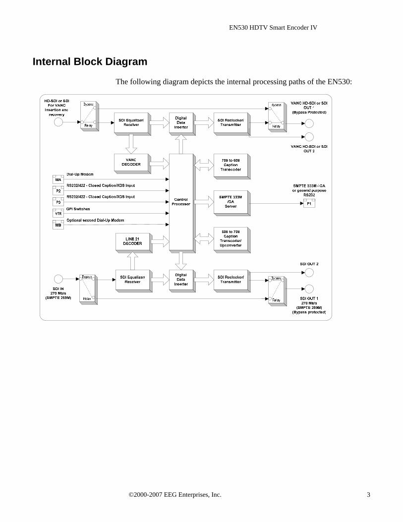
Internal Block Diagram
The following diagram depicts the internal processing paths of the EN530:
©2000-2007 EEG Enterprises, Inc. 3

EN530 HDTV Smart Encoder IV
eeg
Section 2: Installation
Front Panel
The Encoder front panel is shown in the figure below.
POWER
HDTV SMART ENCODER IVMODEL EN530
ENCODERON
RESET
MODE PORT DATA L21 XDS
eegFARMINGDALE, N.Y.eeg
The front panel has the following controls: POWER Turns power to the Encoder on and off. ENCODER ON Controls relay bypass for HD Out 1 and SD Out 1. HD and SD video paths will
be untouched by the Encoder when bypass is set. The LED indicator is off when the Encoder is bypassed.
RESET Performs a hardware reset. The Encoder will reboot, all operations will be
cleared, and status will return to the default settings stored in Non-Volatile Memory.
©2000-2007 EEG Enterprises, Inc. 4
EN530 HDTV Smart Encoder IV
Front Panel LCD The front panel LCD displays information about the Encoder’s current and recent operations. The top row of the display corresponds to primary caption channel operations, and the bottom row corresponds to secondary caption channel operations.
Mode displays an abbreviation corresponding to the Local Entry Mode that was last entered for each captioning service. For a list of Local Entry Modes and abbreviations, see page 12.
Port indicates the port that last input SD captioning and the baud rate at which it is operating.
Data displays Input and Output icons that blink to indicate transmission or reception of 608 serial data for each service. A blinking “I” indicates that the Encoder is receiving caption data from an input port. A blinking “O” indicates that the Encoder is inserting this data into output video signals.
L21 displays Input and Output icons that blink to indicate transmission or reception of 608 Line 21 data for each service. A blinking “I” indicates that the Encoder is receiving caption data from the SD video input. A blinking “O” indicates that the Encoder is inserting this data into output video signals.
XDS displays an Output icon that blinks to indicate transmission of data. A blinking “O” indicates that the Encoder is inserting XDS packets from its queue into output video signals. The rightmost column in the display indicates the presence of HD and SDI video sources. The top row will display SDI if a video source is present at the rear panel SD-SDI IN, and the bottom row will display HD if a video source is present at the HD-SDI IN. If an SDI signal is connected to HD-SDI IN for SDI VANC encoding, the HD indicator will appear.
©2000-2007 EEG Enterprises, Inc. 5
EN530 HDTV Smart Encoder IV
Rear Panel
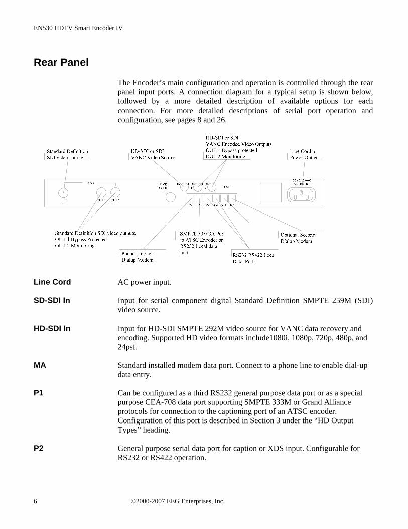
The Encoder’s main configuration and operation is controlled through the rear panel input ports. A connection diagram for a typical setup is shown below, followed by a more detailed description of available options for each connection. For more detailed descriptions of serial port operation and configuration, see pages 8 and 26.
Line Cord AC power input. SD-SDI In Input for serial component digital Standard Definition SMPTE 259M (SDI)
video source. HD-SDI In Input for HD-SDI SMPTE 292M video source for VANC data recovery and
encoding. Supported HD video formats include1080i, 1080p, 720p, 480p, and 24psf.
MA Standard installed modem data port. Connect to a phone line to enable dial-up
data entry. P1 Can be configured as a third RS232 general purpose data port or as a special
purpose CEA-708 data port supporting SMPTE 333M or Grand Alliance protocols for connection to the captioning port of an ATSC encoder. Configuration of this port is described in Section 3 under the “HD Output Types” heading.
P2 General purpose serial data port for caption or XDS input. Configurable for
RS232 or RS422 operation.
©2000-2007 EEG Enterprises, Inc. 6
EN530 HDTV Smart Encoder IV
P3 General purpose serial data port for caption or XDS input. Configurable for RS232 or RS422 operation. As the Master configuration port, P3 is the only port that can enter some Encoder commands.
VTR (GPI) This 6-pin connector is configured as 4 unique GPI switches. The GPI switches
can be used to change caption up-conversion and down-conversion settings and to control caption display relocation to prevent overlap with emergency information and graphics. See page 27 for the GPI input pin-outs.
MB Optional second modem data port. Connect to a phone line to enable dial-up
data entry. Time Code Not used
SD-SDI Out Standard Definition SMPTE 259M video output. OUT 1 is the primary output.
OUT 2 is for monitoring or other secondary use. Only OUT 1 is affected by ENCODER ON bypass.
HD-SDI/SDI Out VANC data encoded HD-SDI SMPTE 292M video output. OUT 1 is the
primary output. OUT 2 is for monitoring or other secondary use. Only OUT 1 is affected by ENCODER ON bypass.
©2000-2007 EEG Enterprises, Inc. 7
EN530 HDTV Smart Encoder IV
Data Port Settings
The EN530 serial data input ports P2 and P3 are factory configured for RS232 protocol at 1200 baud, 7 data bits, and Odd parity. The dial-up modem is set to operate at 2400 baud, but will also operate at 1200 baud without reconfiguration. These default settings are adequate for most purposes. To change any of these settings, see pages 26. The EN530 controls the flow of data from input ports to the processing queue using XON/XOFF handshaking protocol. XOFF will be sent when the queue is over ¾ full. When the queue clears to ¼ full, XON will be sent. The XON and XOFF characters are sent with a parity bit determined by the parity setting of the port they are sent through. Hardware handshaking is not supported and must be disabled when connecting the Encoder. P1 is factory configured for connection to the captioning port of an ATSC encoder that uses SMPTE 333M protocol. It can also be configured as a standard data port (similar to P2 and P3), or to support an ATSC encoder that uses Grand Alliance (GA) protocol. To reconfigure P1, see page 11.
Serial Input Activity While any of the EN530’s serial input ports (MA, P3, P2, and P1 if configured)
may enter data for any supported caption service, it is important to note that multiple ports may not enter data for the same service simultaneously. When an input port begins a local data entry mode for a service, any other port that was previously entering data for that service will be preempted, and any further data entered through that port will be lost. Therefore, coordination must be exercised in multiple supplier captioning environments to avoid interference and unintended data loss in switching. The EN530 gives special priority to data entry from the dial-up modem. Once MA is Off Hook and begins a data entry mode for a service, only P3 may preempt the modem and take over data entry for that service. MA will retain this priority until either P3 takes over or the modem returns On Hook.
©2000-2007 EEG Enterprises, Inc. 8

EN530 HDTV Smart Encoder IV
eeg
Section 3: Encoder Operation
Command Format
The EN530 command set is an extension of the industry standard Smart Encoder command set used in the EEG 470 series encoders. Most commands in the EN530 command set can be entered through any serial input port or through the dial-up modem; any commands that can be entered only through master configuration port P3 will be specially identified. Encoder commands are recognized by a leading control code of <CTRL+A>, also represented by the ASCII hex code 01. The <CTRL+A> character is non-printing on most terminal screens, but on some it appears as a smiley face. An Encoder control command must end with a carriage return, which can be entered with the <ENTER> key on a keyboard or by 0D in ASCII hex. To send the encoder commands through the serial input ports, connect a standard 9-pin cable between your PC’s serial port and the RJ11 to DB9 adapter shipped with the EN530, and then connect the other end of the adapter to any encoder data port. You can now send commands to the encoder, from your PC, using a communications application such as HyperTerminal, which is bundled with most versions of Windows. The most basic Smart Encoder command, useful for checking the operation of your communication setup, is <CTRL+A>?<ENTER>. If your setup is working correctly, the Encoder will respond with its model name, firmware version, and serial number. If you have trouble communicating using HyperTerminal, always check to make sure that the settings in the Port Settings menu in HyperTerminal match the settings for the Encoder port you are connecting to.
In this manual, Encoder commands will be distinguished from other text by use of a bold font. The parameters for each command will be listed in italics. Optional parameters will be enclosed in square brackets. Possible parameter values and default settings will be described in text or bullet points after the command is introduced.
©2000-2007 EEG Enterprises, Inc. 9
EN530 HDTV Smart Encoder IV
HD Output Types
The EN530 is capable of outputting HD caption data in three different ways. The HD output type you will want to use will be determined based on the EN530’s placement in your broadcast or post-production video path, and sometimes the protocols supported by the equipment it is interfaced with.
HD VANC Insertion In HD VANC Insertion, the EN530 inserts its EIA-708B caption output data, either regenerated data from the HD input, up-converted data from the SD input, or locally-inserted data from the data ports, into the vertical ancillary space of an HD video source, using SMPTE 334M protocol. The newly captioned HD video signal appears at the HD-SDI video outputs on the rear panel.
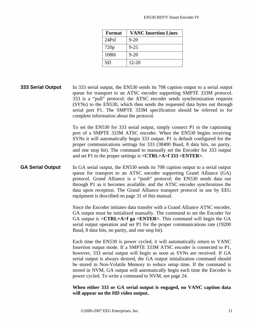
The Encoder’s default HD output mode will be VANC Insertion unless the P1 port is connected to an ATSC encoder supporting the SMPTE 333M protocol. The Encoder will return to VANC insertion mode if the device supporting SMPTE 333M is disconnected. VANC insertion can also be disabled by typing <CTRL+A># OFF <ENTER>. If insertion is disabled through this command, it must be re-enabled using <CTRL+A># ON <ENTER>. The command to return to VANC insertion with automatic SMPTE 333M detection on P1 from another mode, or to change the VANC line on which insertion takes place is <CTRL+A>f 334 [Line] <ENTER>. To enter VANC Insertion mode without automatic 333 detection, use <CTRL+A>f vanc [Line] <ENTER>. This will allow P1 to be used as a general purpose serial input port. The optional Line parameter sets the VANC line on which caption data will be inserted into the HD video signal. Non-captioning VANC data packets on that line will be preserved. The following table lists the valid VANC insertion lines for the most common HD video formats. The Encoder’s default insertion line is the first available VANC line of the particular video standard, which is valid for all formats. Entering 0 as the Line parameter will set insertion for the first available VANC line, using the order listed in the table below for each format. In interlaced formats, caption data will only be inserted once per frame, in the first field.
©2000-2007 EEG Enterprises, Inc. 10
EN530 HDTV Smart Encoder IV
Format VANC Insertion Lines 24Psf 9-20 720p 9-25 1080i 9-20 SD 12-20
333 Serial Output In 333 serial output, the EN530 sends its 708 caption output to a serial output
queue for transport to an ATSC encoder supporting SMPTE 333M protocol. 333 is a “pull” protocol; the ATSC encoder sends synchronization requests (SYNs) to the EN530, which then sends the requested data bytes out through serial port P1. The SMPTE 333M specification should be referred to for complete information about the protocol. To set the EN530 for 333 serial output, simply connect P1 to the captioning port of a SMPTE 333M ATSC encoder. When the EN530 begins receiving SYNs it will automatically begin 333 output. P1 is default configured for the proper communications settings for 333 (38400 Baud, 8 data bits, no parity, and one stop bit). The command to manually set the Encoder for 333 output and set P1 to the proper settings is <CTRL+A>f 333 <ENTER>.
GA Serial Output In GA serial output, the EN530 sends its 708 caption output to a serial output
queue for transport to an ATSC encoder supporting Grand Alliance (GA) protocol. Grand Alliance is a “push” protocol; the EN530 sends data out through P1 as it becomes available, and the ATSC encoder synchronizes the data upon reception. The Grand Alliance transport protocol in use by EEG equipment is described on page 31 of this manual.
Since the Encoder initiates data transfer with a Grand Alliance ATSC encoder, GA output must be initialized manually. The command to set the Encoder for GA output is <CTRL+A>f ga <ENTER>. This command will begin the GA serial output operation and set P1 for the proper communications rate (19200 Baud, 8 data bits, no parity, and one stop bit).
Each time the EN530 is power cycled, it will automatically return to VANC
Insertion output mode. If a SMPTE 333M ATSC encoder is connected to P1, however, 333 serial output will begin as soon as SYNs are received. If GA serial output is always desired, the GA output initialization command should be stored in Non-Volatile Memory to reduce setup time. If the command is stored in NVM, GA output will automatically begin each time the Encoder is power cycled. To write a command to NVM, see page 24.
When either 333 or GA serial output is engaged, no VANC caption data will appear on the HD video output.
©2000-2007 EEG Enterprises, Inc. 11
EN530 HDTV Smart Encoder IV
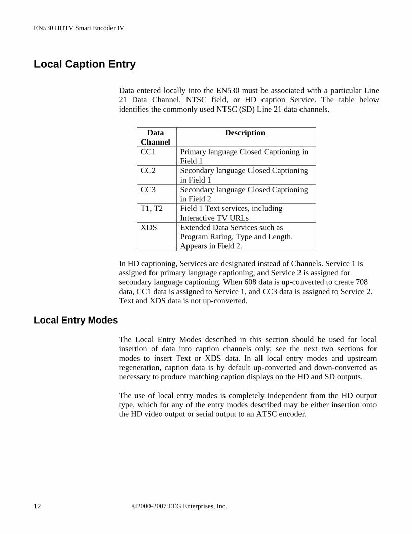
Local Caption Entry Data entered locally into the EN530 must be associated with a particular Line
21 Data Channel, NTSC field, or HD caption Service. The table below identifies the commonly used NTSC (SD) Line 21 data channels.
Data Channel
Description
CC1 Primary language Closed Captioning in Field 1
CC2 Secondary language Closed Captioning in Field 1
CC3 Secondary language Closed Captioning in Field 2
T1, T2 Field 1 Text services, including Interactive TV URLs
XDS Extended Data Services such as Program Rating, Type and Length. Appears in Field 2.
In HD captioning, Services are designated instead of Channels. Service 1 is assigned for primary language captioning, and Service 2 is assigned for secondary language captioning. When 608 data is up-converted to create 708 data, CC1 data is assigned to Service 1, and CC3 data is assigned to Service 2. Text and XDS data is not up-converted.
Local Entry Modes
The Local Entry Modes described in this section should be used for local insertion of data into caption channels only; see the next two sections for modes to insert Text or XDS data. In all local entry modes and upstream regeneration, caption data is by default up-converted and down-converted as necessary to produce matching caption displays on the HD and SD outputs. The use of local entry modes is completely independent from the HD output type, which for any of the entry modes described may be either insertion onto the HD video output or serial output to an ATSC encoder.
©2000-2007 EEG Enterprises, Inc. 12

EN530 HDTV Smart Encoder IV
Regeneration Mode Appears on front panel display as REGEN. Upstream regeneration is used whenever no local entry mode is in effect for a caption channel. The Encoder’s default Regeneration action is to strip both the SD and HD video of upstream captioning, and then regenerate the caption data recovered from the HD video input on both outputs. If no upstream HD captioning is present, caption data from the SD video input will be used instead.
The default Regeneration response is configurable by using the commands listed in this section, and also by setting the Block 608 Up-conversion GPI switch (see page 27).
Regenerate Upstream VANC <CTRL+A>! [ON/OFF] <ENTER>
Instructs the Encoder to either detect and potentially regenerate (default) or ignore incoming VANC data from the HD video input. If the encoder is set to ignore upstream VANC data, output signals will include only caption data recovered and regenerated from the SD video input. Use OFF to ignore upstream VANC caption data, and ON to resume detecting upstream VANC caption data.
Ignore Upstream L21 Channel <CTRL+A>6 Channel <ENTER> Return Upstream L21 Channel <CTRL+A>7 Channel <ENTER>
Instructs the Encoder to ignore incoming Line 21 data from the SD video input in the specified caption channel. When Line 21 data in a channel is ignored, output signals will not contain any caption data recovered from the SD video input in that channel, even if there are no other data sources available. Channel sets the incoming Line 21 channel to be turned off. This
parameter may be set for any NTSC Caption or Text channel. Upstream XDS data cannot be turned off with this command.
708 Down-conversion <CTRL+A>h [ON/OFF] <ENTER>
Use the 708 Down-conversion command to set whether or not 708 caption data recovered from the HD video input is down-converted and encoded to the SD video output. The default down-conversion setting varies based on the firmware version of your Encoder. Enter the command without a parameter to check the current setting.
©2000-2007 EEG Enterprises, Inc. 13
EN530 HDTV Smart Encoder IV
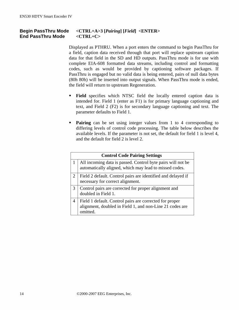
Begin PassThru Mode <CTRL+A>3 [Pairing] [Field] <ENTER> End PassThru Mode <CTRL+C>
Displayed as PTHRU. When a port enters the command to begin PassThru for a field, caption data received through that port will replace upstream caption data for that field in the SD and HD outputs. PassThru mode is for use with complete EIA-608 formatted data streams, including control and formatting codes, such as would be provided by captioning software packages. If PassThru is engaged but no valid data is being entered, pairs of null data bytes (80h 80h) will be inserted into output signals. When PassThru mode is ended, the field will return to upstream Regeneration. Field specifies which NTSC field the locally entered caption data is
intended for. Field 1 (enter as F1) is for primary language captioning and text, and Field 2 (F2) is for secondary language captioning and text. The parameter defaults to Field 1.
Pairing can be set using integer values from 1 to 4 corresponding to
differing levels of control code processing. The table below describes the available levels. If the parameter is not set, the default for field 1 is level 4, and the default for field 2 is level 2.
Control Code Pairing Settings 1 All incoming data is passed. Control byte pairs will not be
automatically aligned, which may lead to missed codes.
2 Field 2 default. Control pairs are identified and delayed if necessary for correct alignment.
3 Control pairs are corrected for proper alignment and doubled in Field 1.
4 Field 1 default. Control pairs are corrected for proper alignment, doubled in Field 1, and non-Line 21 codes are omitted.
©2000-2007 EEG Enterprises, Inc. 14
EN530 HDTV Smart Encoder IV
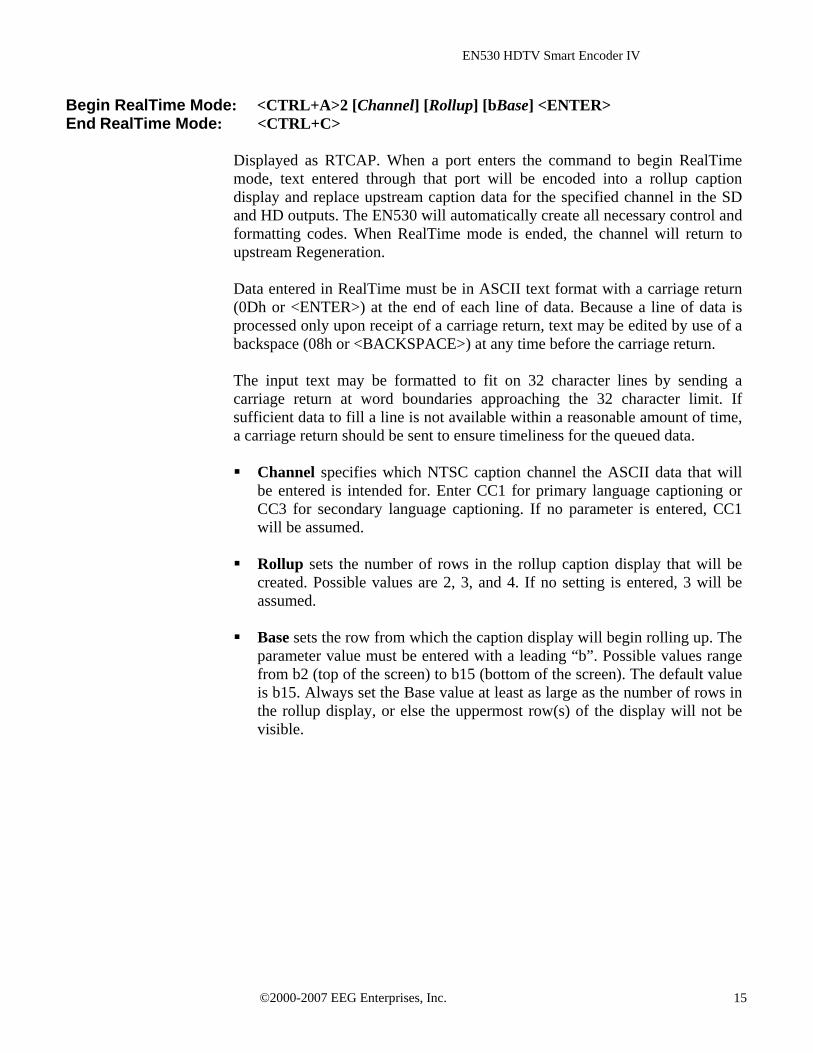
Begin RealTime Mode: <CTRL+A>2 [Channel] [Rollup] [bBase] <ENTER> End RealTime Mode: <CTRL+C>
Displayed as RTCAP. When a port enters the command to begin RealTime mode, text entered through that port will be encoded into a rollup caption display and replace upstream caption data for the specified channel in the SD and HD outputs. The EN530 will automatically create all necessary control and formatting codes. When RealTime mode is ended, the channel will return to upstream Regeneration. Data entered in RealTime must be in ASCII text format with a carriage return (0Dh or <ENTER>) at the end of each line of data. Because a line of data is processed only upon receipt of a carriage return, text may be edited by use of a backspace (08h or <BACKSPACE>) at any time before the carriage return. The input text may be formatted to fit on 32 character lines by sending a carriage return at word boundaries approaching the 32 character limit. If sufficient data to fill a line is not available within a reasonable amount of time, a carriage return should be sent to ensure timeliness for the queued data. Channel specifies which NTSC caption channel the ASCII data that will
be entered is intended for. Enter CC1 for primary language captioning or CC3 for secondary language captioning. If no parameter is entered, CC1 will be assumed.
Rollup sets the number of rows in the rollup caption display that will be
created. Possible values are 2, 3, and 4. If no setting is entered, 3 will be assumed.
Base sets the row from which the caption display will begin rolling up. The
parameter value must be entered with a leading “b”. Possible values range from b2 (top of the screen) to b15 (bottom of the screen). The default value is b15. Always set the Base value at least as large as the number of rows in the rollup display, or else the uppermost row(s) of the display will not be visible.
©2000-2007 EEG Enterprises, Inc. 15

EN530 HDTV Smart Encoder IV
XDS Insertion
Extended Data Services (XDS) is an NTSC Field 2 data channel that provides information to viewers about the program that is being aired. On SD broadcasts, XDS is used to transmit program ratings to allow viewer V-chip filtering of mature content. Although HD broadcasts do not use XDS for V-chip compliance, XDS data must still be included in compatibility bytes for set top down-conversion. The EN530 includes all of the XDS functionality of the broadcast industry’s leading XDS solution, the EN470 Smart Encoder III. XDS data packets can be loaded into the Encoder’s queue with one simple command, and be held for any specified time period. Each individual packet type can be independently set for upstream or local priority, and permanent packets can be stored in Non Volatile Memory and inserted automatically whenever the Encoder is operating. Packets are inserted into output video signals using EEG’s proprietary Stochastic Scheduling Algorithm. The Stochastic Scheduling Algorithm is a finely tuned solution to the Field 2 bandwidth limitations that cause difficulties in XDS packet transmission. A Priority level is automatically assigned to each packet based on its XDS Class and Type. The Stochastic Scheduling Algorithm ensures both that high priority packets like V-chip data and program names are transmitted frequently enough to be instantly accessible for new viewers, and that lower priority packets are guaranteed to be inserted periodically, and not preempted completely. As per EIA-608B specifications, all available Field 2 space is filled, rescheduling and regeneration are automatically performed on all upstream packets, and packet continuations are applied when necessary. Additionally, upstream XDS program packets will continue to transmit for five minutes after any non-clearing upstream interruption, such as a commercial break or undesired outage.
Enable XDS Entry <CTRL+A>O XDS O <ENTER>
This command must be entered to enable a port for XDS input. A port must be enabled for XDS input in order to accept XDS data and control commands. The character repeated in the command is a capital o and not a zero.
©2000-2007 EEG Enterprises, Inc. 16

EN530 HDTV Smart Encoder IV
Load XDS Packet <CTRL+A>P Packet Duration Content [Priority] <ENTER>
Creates an XDS packet and loads it into the XDS queue. The Encoder will begin inserting the packet immediately.
Packet sets the XDS Class and Type of the packet that will be created. If a
new packet is loaded with the same Packet ID as an existing packet in the queue, the pre-existing packet will be deleted; if the new packet is a Program Name or Program ID packet, all program-specific packets will be deleted from the queue. A packet loaded into the Encoder with the Load XDS Packet command has local priority; in output signals, it will replace all upstream packets of the same Class and Type. The Packet parameter should be entered as Class immediately followed by Type in the way shown in the table below. Leading zeroes may be omitted. The Class and Type of a few of the most commonly used XDS packets are shown in the following table; for a complete list refer to EIA-608B.
Class/Type Content Class/Type Content0102 Current Program Length 0501 Network Name 0103 Current Program Name 0502 Station ID (Call Letters) 0105 Current Program Rating 0504 TSID
Duration sets the transmission duration of the newly created packet. When a packet’s duration period expires, it will be deleted from the XDS queue. A duration setting of –1 will cause the packet to be inserted until it is deleted by a future command. An integer setting (i.e. 100) will be interpreted as the number of times to output the packet before deleting it. An Elapsed Time setting (i.e. 00.45.00), will cause the packet to be inserted for that length of time, beginning when the command is entered, and then deleted.
Content sets the information content of the packet. Content can be entered
in ASCII text enclosed in curly braces, { }, or in ASCII Hex notation. A checksum need not be enclosed, as the Encoder will calculate it automatically before insertion.
©2000-2007 EEG Enterprises, Inc. 17

EN530 HDTV Smart Encoder IV
Priority is an optional parameter that allows the output priority of a packet to be customized. The parameter should not be used for standardized, commonly used packets, which the Encoder automatically assigns appropriate priorities. The parameter is useful for custom, user-defined packets. The default priority for packets that the encoder does not recognize is 115, which corresponds to a fairly low priority. A typical high priority value is 30. A packet’s numerical priority is inversely proportional to the frequency with which it is inserted.
Two sample XDS entries follow. <CTRL+A>P 103 –1 {Evening News} <ENTER> will load and begin insertion for a current program name packet reading “Evening News.” The packet will be output until a new packet is entered. <CTRL+A>P 105 00.30.00 4844 <ENTER> will load and begin insertion for a current program rating packet of TV-PG. The packet will be inserted for the next thirty minutes. Refer to EIA-608B for a listing of hex codes for other possible program ratings.
Load Default XDS Packet
<CTRL+A>P LPacket Duration Content [Holdoff] <ENTER> Loads an Upstream Priority XDS packet. This is called a “default” packet because it will be output only when no XDS packet of the specified Class and Type is present in the incoming video signal. When an upstream packet is discontinued without a replacement or a Clear packet (two Space characters), the Encoder will continue insertion of the discontinued packet for a time-out period of 5 minutes to ensure continuity during program breaks. The default packet will then be transmitted until the upstream packet is replaced. The Packet, Duration, and Content parameters are the same as for the local priority Load XDS Packet command explained on the previous page, except the Packet Class/Type must be entered with a leading “L”. Holdoff sets the number of seconds after which the default packet will
begin transmission once the five minute upstream time-out period expires. The default is zero.
Example: <CTRL+A>P L105 –1 4840 <ENTER> will create a default program rating packet of None. This packet will be inserted beginning 5 minutes after an interruption in upstream program rating data, and will continue to be transmitted indefinitely until upstream data resumes.
©2000-2007 EEG Enterprises, Inc. 18
EN530 HDTV Smart Encoder IV
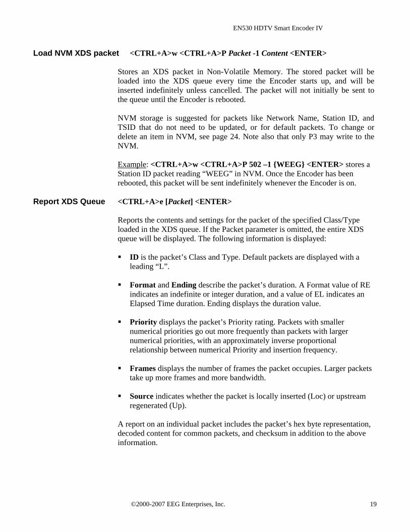
Load NVM XDS packet <CTRL+A>w <CTRL+A>P Packet -1 Content <ENTER> Stores an XDS packet in Non-Volatile Memory. The stored packet will be loaded into the XDS queue every time the Encoder starts up, and will be inserted indefinitely unless cancelled. The packet will not initially be sent to the queue until the Encoder is rebooted. NVM storage is suggested for packets like Network Name, Station ID, and TSID that do not need to be updated, or for default packets. To change or delete an item in NVM, see page 24. Note also that only P3 may write to the NVM. Example: <CTRL+A>w <CTRL+A>P 502 –1 {WEEG} <ENTER> stores a Station ID packet reading “WEEG” in NVM. Once the Encoder has been rebooted, this packet will be sent indefinitely whenever the Encoder is on.
Report XDS Queue <CTRL+A>e [Packet] <ENTER>
Reports the contents and settings for the packet of the specified Class/Type loaded in the XDS queue. If the Packet parameter is omitted, the entire XDS queue will be displayed. The following information is displayed: ID is the packet’s Class and Type. Default packets are displayed with a
leading “L”. Format and Ending describe the packet’s duration. A Format value of RE
indicates an indefinite or integer duration, and a value of EL indicates an Elapsed Time duration. Ending displays the duration value.
Priority displays the packet’s Priority rating. Packets with smaller
numerical priorities go out more frequently than packets with larger numerical priorities, with an approximately inverse proportional relationship between numerical Priority and insertion frequency.
Frames displays the number of frames the packet occupies. Larger packets
take up more frames and more bandwidth. Source indicates whether the packet is locally inserted (Loc) or upstream
regenerated (Up). A report on an individual packet includes the packet’s hex byte representation, decoded content for common packets, and checksum in addition to the above information.
©2000-2007 EEG Enterprises, Inc. 19

EN530 HDTV Smart Encoder IV
Delete XDS Packet <CTRL+A>P Packet <ENTER>
Deletes the packet of the specified Class and Type from the XDS queue. If the packet is a Program Name or Program ID packet, all other program-specific packets will also be deleted, and the Encoder will insert a Clear packet for downstream databases and decoders.
Delete XDS Queue <CTRL+A>L -all <ENTER>
Deletes all packets in the XDS queue. Packets loaded from NVM will be removed from the queue but will remain in NVM storage.
Block Upstream XDS <CTRL+A>T -Class00 <ENTER> End Blocking <CTRL+A>T Class00 <ENTER>
Blocks all incoming packets of the specified Class. Entering all instead of Class00 as the parameter will cause all upstream packets to be blocked. Omitting the Class parameter will cause the block/pass status for each Class to be reported. Example: <CTRL+A>T –0100 <ENTER> blocks all upstream XDS packets in the Current Program Class. <CTRL+A>T 0100 <ENTER> will resume normal XDS operation.
©2000-2007 EEG Enterprises, Inc. 20
EN530 HDTV Smart Encoder IV
URL and Text Encoding
The EN530 handles URL and Text Encoding, like XDS, as an output from memory function, rather than a real time flow function. The EN530 can store up to 24 separate text messages and interactive television URLs in RAM storage indefinitely. Messages in storage may be transmitted in any sequence and repeated any number of times in either Field 1 text channel. However, both channels cannot use the same message simultaneously. Once insertion of a message begins, upstream data on that Text channel is blocked until the locally inserted message is completed. The URL insertion protocol operates in T2 and is fully compliant with EIA-608B specifications.
Begin Message Input <CTRL+A>0 Title [Channel] [Repeat] [K/D] [O/H] [N/L] <ENTER> End Message Input <CTRL+C>
To load a new message, enter the Begin Message Input command. The character following <CTRL+A> in the Begin command is a zero. The Encoder should respond with “>” as a prompt at the beginning of the message and at the beginning of each new line. Enter the message text, ending each line with a carriage return (0Dh or <ENTER>). For URL insertion, be certain to observe the format defined in EIA-608B, which includes specific ordering, punctuation, and a checksum. When the message is finished, enter a final carriage return, and then the End Message Input command. To insert a transmission delay within the message, insert the command <CTRL+B> Delay at the desired point, setting Delay equal to the length of the desired delay in seconds.
Title sets the title of the message. The title will be used to identify the
message for future use. Channel sets the Text Channel queue (T1 or T2) into which the message
will be inserted. T1 is the default. Repeat sets the integer number of times that the message will be repeated
when it arrives in the queue. All messages in the queue are cycled, and any message that has not reached its Repeat count returns to the end of the queue line after it is inserted. The default setting is infinite repeat (listed as FFFF in a status display).
K/D specifies whether the article is to be Kept in memory or Deleted once
it exits the queue. The default setting is Delete. O/H instructs the Encoder to either Output the article to the appropriate
channel queue immediately or to Hold it in memory for future use. Immediate output is the default setting.
©2000-2007 EEG Enterprises, Inc. 21
EN530 HDTV Smart Encoder IV
N/L specifies whether the message is to be placed Next in line or Last in
line when it is sent to an output queue. The default setting is Last. Example: <CTRL+A>0 EEG_URL T2 3 D O N <ENTER> EEG on the Web <ENTER> <http://www.eegent.com>[t:p][C510]<ENTER> <CTRL+C> will create a two line message that displays and identifies a URL address. The use of brackets, attributes, and checksum is per EIA-608B specification. The message will be placed next in the T2 output queue, inserted 3 times, and then deleted.
Output Message <CTRL+A>1 Title [Channel] [Repeat] [K/D] [O/H] [N/L] <ENTER>
Places a previously stored message into the appropriate text channel output queue. Any parameters that are not specified will retain the values the message was last stored with. The character following <CTRL+A> in the command is a one. If O/H is set to H, the message will not be output, and this command can be used to change the messages’ parameters.
Remove Message from Queue <CTRL+A>4 Title [K/D] <ENTER>
Removes all instances of the specified message from the output queue. If the last K/D parameter associated with the message is D, the message will also be deleted from memory. If the message is being output as this command is received, the current repetition will be allowed to finish.
©2000-2007 EEG Enterprises, Inc. 22

EN530 HDTV Smart Encoder IV
Display Message Status <CTRL+A>9 [Channel] <ENTER>
Displays the names and settings of the messages currently associated with the specified Channel. If the Channel parameter is omitted, displays the names and setting of all saved messages.
Begin Set Output Queue <CTRL+A>8 [Channel] <ENTER> End Set Output Queue <CTRL+C>
To set the message output queue for a Channel, first enter the Begin Set Output Queue command. T1 is the default channel. A prompt reading “>” should appear. Enter the desired Messages, delineated by carriage returns, in the desired order of insertion. When the list is completed, enter the End Set Output Queue command. A message that is associated with a different channel cannot be added to the queue.
Display Output Queue <CTRL+A>B <ENTER>
Displays the contents of both text channel output queues.
©2000-2007 EEG Enterprises, Inc. 23
EN530 HDTV Smart Encoder IV
eeg
Section 4: Additional Features
Non-Volatile Memory
The EN530 can store up to 32 commands in Non-Volatile Memory (NVM). When the Encoder is powered up or reset, any commands stored in NVM are executed as part of the startup process. Setup or initialization commands that are always desired, as well as permanently applicable XDS packets, can be entered in NVM to reduce setup time after both deliberate and accidental Encoder power cycles. While any serial port may read from NVM or execute NVM commands assigned to it, only P3 may write to the NVM.
New NVM Command <CTRL+A>w Port [List] Command <ENTER>
Enters an Encoder command for NVM storage. The command, which must be entered in complete form including the initial <CTRL+A>, will be executed as if entered through the specified port each time the Encoder is turned on or reset. NVM commands are executed in order of list number. If no list number is specified, the command will be assigned the next available number. Example: <CTRL+A>w MA <CTRL+A>O XDS O <ENTER> will be stored in NVM and will enable MA, the dial up modem, for XDS entry each time the Encoder starts up.
List NVM Commands <CTRL+A>x <ENTER>
Returns a numbered list of commands stored in NVM.
Delete NVM Command <CTRL+A>w List <ENTER>
Deletes the command with the specified list number from NVM. The remaining commands in the list will be renumbered to fill the empty list number left by a deletion. If “-a” is specified as the list number, all commands in NVM will be deleted.
©2000-2007 EEG Enterprises, Inc. 24
EN530 HDTV Smart Encoder IV
Set Clock <CTRL+A>c Time [Zone] [DST] <ENTER>
Sets the Encoder’s internal clock and stores the settings in Non-Volatile Memory. If no parameters are entered, returns current settings. This information is only used for the optional generation of the Time of Day XDS packet. Time is the local time on a 24-hour clock, in the format HH:MM:SS.
Zone is the local time zone, expressed by the number of hours local time
differs from UTC time. For example, Eastern Standard Time would be entered as 5. If the parameter is omitted, current setting will be retained.
DST sets the Daylight Savings Time status and can be entered as ON or
OFF. If the parameter is omitted, current setting will be retained.
Set Date <CTRL+A>d Date <ENTER>
Sets the Encoder’s internal clock for the date and stores the settings in Non-Volatile Memory. If no parameters are entered, returns current settings. This information is only used for the optional generation of the Date XDS packet. The Date parameter must be entered in the form MM/DD/YY W where MM is the month (01-12), DD is the date (01-31), YY is the year (00-99) and W is the day of the week (1-7, with 1 representing Sunday).
List PROM Messages <CTRL+A>J <ENTER>
Returns a list of messages stored in the Encoder’s PROM. The PROM may store up to 8 factory configured commands that execute upon power up or reset. If PROM commands are present, they are executed before NVM commands.
©2000-2007 EEG Enterprises, Inc. 25

EN530 HDTV Smart Encoder IV
Serial Port Configuration Change Baud Rate <CTRL+A>I [Port] Baud Bits Parity <ENTER>
As Master port, P3 can change the communication settings of any of the serial input ports. Each other port may change only its own settings. Any changes in communication settings take effect immediately; thus, after commanding a change in settings through a port, the user must immediately begin communicating at the new settings. Port specifies the port that is being reconfigured. The parameter may be
omitted if the port the command is entered through and the port being reconfigured are the same. Enter P2, P3, MA, or VTR.
Baud sets the new baud rate for the port. Supported rates are 1200, 2400,
4800, and 9600. Bits sets the number of data bits. Choose either 7 or 8.
Parity sets the parity bit. Choose either o for odd, e for even, or n for none.
Data Port Pin Assignments
The rear panel serial port connectors have six contacts each. The pin assignments for each port and configuration are shown in the following table.
1→ 6
Pin P1-3, RS232
P1-3, RS422
MA, MB Telco
GPI (VTR)
1 Rx- Switch 4 2 Ground Common 3 Tx Tx- L2 Switch 3 4 Rx Tx+ L1 Switch 2 5 Ground Common Switch 1 6 Rx+ Ground
©2000-2007 EEG Enterprises, Inc. 26
EN530 HDTV Smart Encoder IV
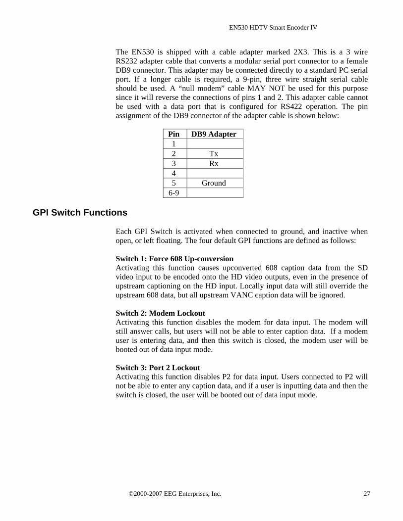
The EN530 is shipped with a cable adapter marked 2X3. This is a 3 wire RS232 adapter cable that converts a modular serial port connector to a female DB9 connector. This adapter may be connected directly to a standard PC serial port. If a longer cable is required, a 9-pin, three wire straight serial cable should be used. A “null modem” cable MAY NOT be used for this purpose since it will reverse the connections of pins 1 and 2. This adapter cable cannot be used with a data port that is configured for RS422 operation. The pin assignment of the DB9 connector of the adapter cable is shown below:
Pin DB9 Adapter 1 2 Tx 3 Rx 4 5 Ground
6-9 GPI Switch Functions
Each GPI Switch is activated when connected to ground, and inactive when open, or left floating. The four default GPI functions are defined as follows: Switch 1: Force 608 Up-conversion Activating this function causes upconverted 608 caption data from the SD video input to be encoded onto the HD video outputs, even in the presence of upstream captioning on the HD input. Locally input data will still override the upstream 608 data, but all upstream VANC caption data will be ignored. Switch 2: Modem Lockout Activating this function disables the modem for data input. The modem will still answer calls, but users will not be able to enter caption data. If a modem user is entering data, and then this switch is closed, the modem user will be booted out of data input mode. Switch 3: Port 2 Lockout Activating this function disables P2 for data input. Users connected to P2 will not be able to enter any caption data, and if a user is inputting data and then the switch is closed, the user will be booted out of data input mode.
©2000-2007 EEG Enterprises, Inc. 27

EN530 HDTV Smart Encoder IV
Switch 4: Force Regeneration Activating this function causes all locally input caption data to be ignored. Upstream caption data will be regenerated as if no local caption modes were active. The GPI switches can also be configured to perform caption display relocation. Caption displays can be remapped to avoid either the top rows or bottom rows of the television screen to avoid blocking emergency information, news crawls, or other important graphics. The FCC requires that emergency alert information be visible to closed caption viewers.
Configure GPI Switches <CTRL+A>R switch1 switch2 switch3 switch4 <ENTER>
Each of the four parameters assigns a function to the respectively numbered GPI switch. Each parameter should be set to either – (subtract sign), to indicate that the switch should perform its default function (described above), or a two character string that will create a new caption relocation function. The first character of a caption relocation function should be either t to protect an area at the top of the screen by bumping captions down, when necessary, or b to protect an area at the bottom of the screen by bumping captions up. The second character should be an integer between 2 and 4, indicating the number of captioning rows that should be protected. There are 15 logical caption rows in the safe title area of the video, so a row value of 2 will protect 2/15 of the safe title area. Once a caption remapping function has been created, simply short the corresponding GPI switch input to ground in order to activate the function. Example: <CTRL+A>R – b3 t2 - <ENTER> assigns the second GPI switch to protect the bottom 3 rows of the screen from caption overlay and the third switch to protect the top 2 rows, and leaves the first and fourth switches to perform their default operations. To place the above command in NVM so that the encoder will automatically power up in the mode described in the example above, you would enter: <CTRL+A>w p1 <CTRL+A>R – b3 t2 - <ENTER>
©2000-2007 EEG Enterprises, Inc. 28

EN530 HDTV Smart Encoder IV
Encoder Status Commands
Report Identification <CTRL+A>? <ENTER>
Returns the Encoder’s model, serial number, and firmware version.
Report HD Status <CTRL+A>f <ENTER>
Returns the Encoder’s current HD operation setting (334M VANC Insertion, 333M VANC Recovery, or GA VANC Recovery) and the availability of an HD video source (HD-SDI Present or HD-SDI Not Present). If an HD signal is present, the video format of the source and whether or not VANC caption data is present are also reported.
Report Port Activity <CTRL+A>O <ENTER>
Returns a table displaying which ports last entered data for each data type. The port that last entered data for each data type is marked with an A in the table. The data types are primary language captioning (CF1), secondary language captioning (CF2), primary text services (TF1), secondary text services (TF2), and XDS.
Modem Status <CTRL+A>+ [Modem] <ENTER>
Returns the status of the specified modem as either On Hook or Off Hook. The Modem parameter need not be entered to view the status of MA, the built in dial up modem.
Recovery Status <CTRL+A>A <ENTER>
Returns the data recovery status of each Line 21 channel for incoming SD video. ON indicates that data on the channel is being recovered and processed. OFF indicates that the channel has been turned off (see page 13) and incoming data is being ignored.
SD Video Presence <CTRL+A>b <ENTER>
Reports either Video Present or No Video Present to indicate whether or not the Encoder is receiving an SD video signal.
©2000-2007 EEG Enterprises, Inc. 29
EN530 HDTV Smart Encoder IV
Read LCD Display <CTRL+A>N <ENTER>
Returns the current readings on the front panel LCD display. The format is identical to that of the front panel display (see page 4).
Report Switch Setting <CTRL+A>S <ENTER>
Returns the current setting of the front panel ENCODER ON bypass switch.
Report Battery Level <CTRL+A>Y <ENTER>
Returns the status of the battery that maintains the Encoder’s Non-Volatile Memory. GOOD will be returned for a properly functioning battery. BAD will be returned for a battery in need of replacement.
Monitor Line 21 <CTRL+A>5 [Channel] [I/O] <ENTER> End Monitoring <CTRL+C>
Monitors and displays the EIA-608B caption data encoded in the specified channel. The I/O parameter determines whether the incoming (enter as I) or outgoing (O) data is monitored. The default settings are incoming and CC1.
©2000-2007 EEG Enterprises, Inc. 30

EN530 HDTV Smart Encoder IV
eeg
Appendices Appendix A: Grand Alliance Interface Protocol
The following table describes the Data Packet Structure used by EEG equipment to send caption data to Grand Alliance protocol ATSC encoders. This protocol has been proven compatible with encoders from all major manufacturers supporting GA protocol.
Byte Name Value Meaning
0 SOH 0x01 ASCII SOH, start of packet 0x41 ASCII “A”, ATVCC data 0x31 ASCII “1”, NTSC field 1 data
1 Type
0x32 ASCII “2”, NTSC field 2 data 2 Count 5+n Packet size, in bytes, including header
and trailer bytes. 3 Data 1
4 Data 2
2+n Data n
EIA-708 data bytes.
3+n Checksum <varies> 1 byte checksum. The sum of all bytes in the packet must be zero, modulo 256.
4+n EOT 0x04 ASCII EOT, end of packet
Notes: 1. The maximum packet size is 128 (0x80). 2. Because the packet size (Count) includes the header and trailer bytes, the
minimum valid count is 5. This corresponds to a packet with zero data bytes.
3. This packet structure is applied only to the data for the closed caption serial
stream input to the ATSC encoder. Outgoing bytes in the ATSC stream follow the EIA-708B standard.
©2000-2007 EEG Enterprises, Inc. 31
EN530 HDTV Smart Encoder IV
Appendix B: RS422 Configuration
Serial data ports P1, P2 and P3 are individually configurable for RS422 operation. RS422 can be used for greater signal integrity over longer distances.
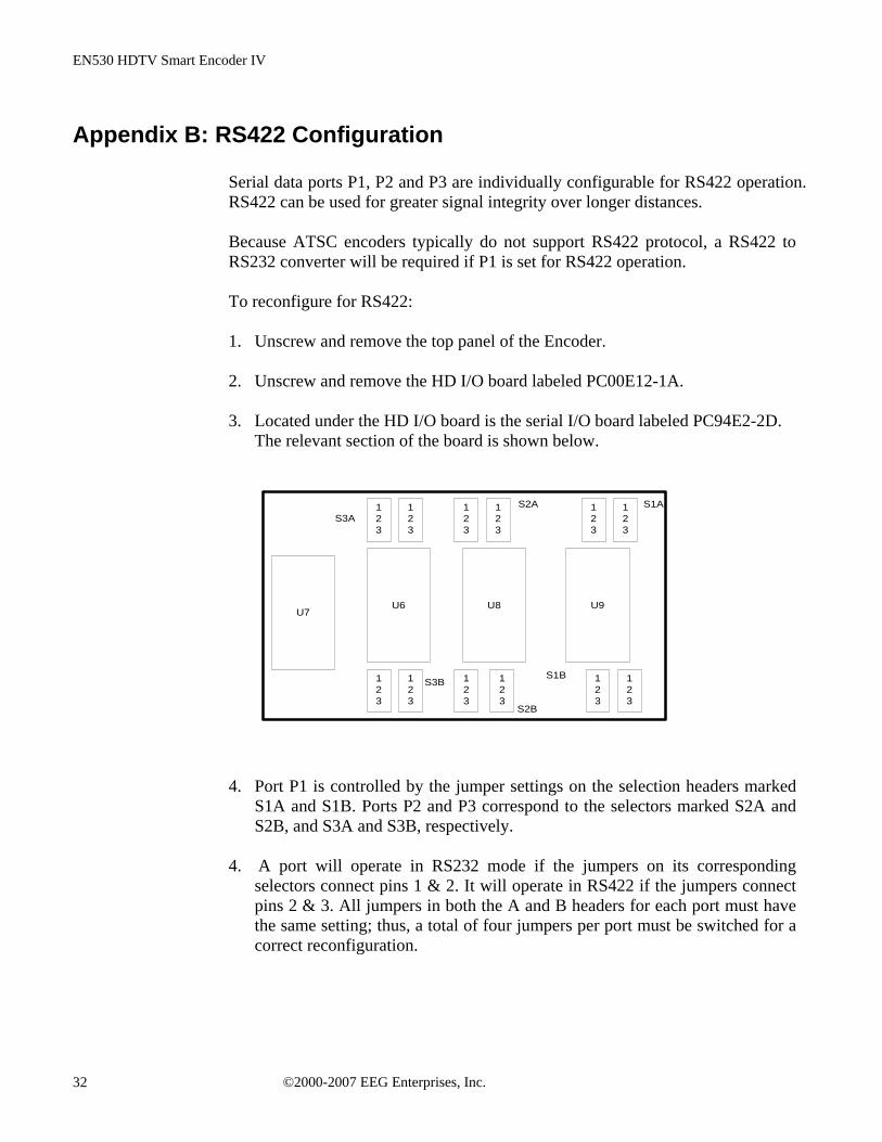
Because ATSC encoders typically do not support RS422 protocol, a RS422 to RS232 converter will be required if P1 is set for RS422 operation. To reconfigure for RS422: 1. Unscrew and remove the top panel of the Encoder. 2. Unscrew and remove the HD I/O board labeled PC00E12-1A. 3. Located under the HD I/O board is the serial I/O board labeled PC94E2-2D.
The relevant section of the board is shown below.
U9U8U6U7
123
123
123
123
123
123
123
123
123
123
123
123
S1A
S1B
S2B
S2AS3A
S3B
4. Port P1 is controlled by the jumper settings on the selection headers marked S1A and S1B. Ports P2 and P3 correspond to the selectors marked S2A and S2B, and S3A and S3B, respectively.
4. A port will operate in RS232 mode if the jumpers on its corresponding
selectors connect pins 1 & 2. It will operate in RS422 if the jumpers connect pins 2 & 3. All jumpers in both the A and B headers for each port must have the same setting; thus, a total of four jumpers per port must be switched for a correct reconfiguration.
©2000-2007 EEG Enterprises, Inc. 32

EN530 HDTV Smart Encoder IV
Appendix C: Clone Port Option
Clone Port is a factory option that configures P2 to transmit duplications of all control commands and data that are received through the dial up modem. This data port can then be connected to an input port on a second Encoder. This allows two or more Encoders performing the same task to be controlled using only one dial-up input.
To use Clone Port on an enabled Encoder, create an RJ11 cable as shown in the diagram below. For RS422 configuration, make sure to respect the reverse tab position shown. Use this cable to connect P2 on the Clone port enabled Encoder to any of the general purpose serial input ports on the second Encoder. Be sure that the baud rates of the two ports match.
TabDown
TabDown
TabDown
TabUp
RS232 Configuration
RS422 Configuration
BLUEYELLOWGREENREDBLACKWHITE
BLUEYELLOWGREENREDBLACKWHITE
BLUE
GREENRED
WHITE
WHITEBLUE
GREEN
RED
Toggle Clone Port <CTRL+A>D ON/OFF <ENTER>
Toggles P2 On or Off as Clone port on a clone port enabled Encoder. This command can only be entered through P3. When P2 is toggled Off for Clone port, it will function normally as a general purpose serial input port. If this command is entered without the On/Off parameter, it will return the current P2 setting. On a Clone port enabled Encoder, Clone port will be automatically toggled On each time the unit is power cycled. Note that P2 will not respond to input commands when Clone port is toggled on.
©2000-2007 EEG Enterprises, Inc. 33

EN530 HDTV Smart Encoder IV
eeg
EN530 Specifications ENCODER HD-SDI INPUT VIDEO CHARACTERISTICS Number of Inputs 1 Connector BNC per IEC 169-8 Format SMPTE 292M 1.485 Gbit/s 1080i, 720p, 480p, 24psF Input Impedance 75 Ohms Equalization Automatic up to 100m @ 1.5 Gb/s w/ Belden 1694 (or equivalent) Video Input Level 800 mV p-p ± 10%, Out 1 bypass protected ENCODER HD-SDI OUTPUT VIDEO CHARACTERISTICS Number of Outputs 2 Program Outputs (Output 1 bypass relay protected) Connector BNC per IEC 169-8 Format SMPTE 292M 1.485 Gbit/s Output Impedance 75 Ohms Output Level 800 mV p-p ± 10% DC Offset 0V ± 0.5V Rise/Fall Time 200pS nominal Overshoot < 10% of amplitude Wide Band Jitter < 0.2 UI ENCODER SD-SDI INPUT VIDEO CHARACTERISTICS Number of Inputs 1 Connector BNC per IEC 169-8 Format 270 Mbits/s component, complies with SMPTE 259M and CCIR 656 Video Input Level 800 mV p-p ± 10%, Out 1 bypass protected Input Impedance 75 Ohms Equalization Automatic up to 200m @ 270 Mb/s w/ Belden 1694 (or equivalent) Input Return Loss >= 18dB, 1-270 MHz Input S/N Ratio Unit will function down to 25 dB ratio (CCIR weighted) with typically one error per row at that
level DATA INPUT CHARACTERISTICS Data Ports Three serial RJ-11 jacks, selectable RS232C / RS422 (RJ-11 to DB9 adapters provided) Serial Data Format 7 data bits, odd parity, 1 stop bit, settable between 1200-9600 baud Modem RJ-11 telephone jack, 1200/2400 baud ENCODER SD-SDI OUTPUT VIDEO CHARACTERISTICS Number of Outputs 2 Program Outputs (Output 1 bypass relay protected) Connector BNC per IEC 169-8 Format 270 Mbits/s component, complies with SMPTE 259M and CCIR 656 Output Impedance 75 Ohms Output Level 800 mV p-p ± 10% DC Offset 0V ± 0.5V Rise/Fall Time 470pS nominal Overshoot < 10% of amplitude Output Return Loss >= 18dB, 1-270 MHz Output Jitter < 300 pS
©2000-2007 EEG Enterprises, Inc. 34
EN530 HDTV Smart Encoder IV
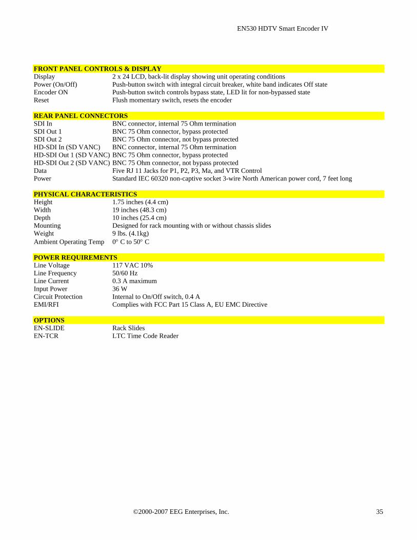
FRONT PANEL CONTROLS & DISPLAY Display 2 x 24 LCD, back-lit display showing unit operating conditions Power (On/Off) Push-button switch with integral circuit breaker, white band indicates Off state Encoder ON Push-button switch controls bypass state, LED lit for non-bypassed state Reset Flush momentary switch, resets the encoder REAR PANEL CONNECTORS SDI In BNC connector, internal 75 Ohm termination SDI Out 1 BNC 75 Ohm connector, bypass protected SDI Out 2 BNC 75 Ohm connector, not bypass protected HD-SDI In (SD VANC) BNC connector, internal 75 Ohm termination HD-SDI Out 1 (SD VANC) BNC 75 Ohm connector, bypass protected HD-SDI Out 2 (SD VANC) BNC 75 Ohm connector, not bypass protected Data Five RJ 11 Jacks for P1, P2, P3, Ma, and VTR Control Power Standard IEC 60320 non-captive socket 3-wire North American power cord, 7 feet long PHYSICAL CHARACTERISTICS Height 1.75 inches (4.4 cm) Width 19 inches (48.3 cm) Depth 10 inches (25.4 cm) Mounting Designed for rack mounting with or without chassis slides Weight 9 lbs. (4.1kg) Ambient Operating Temp 0° C to 50° C POWER REQUIREMENTS Line Voltage 117 VAC 10% Line Frequency 50/60 Hz Line Current 0.3 A maximum Input Power 36 W Circuit Protection Internal to On/Off switch, 0.4 A EMI/RFI Complies with FCC Part 15 Class A, EU EMC Directive OPTIONS EN-SLIDE Rack Slides EN-TCR LTC Time Code Reader
©2000-2007 EEG Enterprises, Inc. 35
EN530 HDTV Smart Encoder IV
References The following specifications have been incorporated into the design of the EN530. They are the definitive sources for additional information regarding the respective technologies that they describe.
ATSC A/53B, ATSC Digital Television Standard, 2001. EIA/CEA-608-B, Line 21 Data Services, 2000. EIA-708-B, Digital Television (DTV) Closed Captioning, 1999. SMPTE 259M, 10-bit 4:2:2 Component and 4fsc Composite Digital Signals – Serial Digital Interface,
1997. SMPTE 291M, Ancillary Data Packet and Space Formatting, 1998. SMPTE 292M, Bit-Serial Digital Interface for High Definition Television Systems, 1998. SMPTE 333M, DTV Closed Caption Server to Encoder Interface, 1999. SMPTE 334M, Vertical Ancillary Data Mapping for Bit-Serial Interface, 2000.
©2000-2007 EEG Enterprises, Inc. 36