head-mounted eye tracker - cornell...
TRANSCRIPT

HEAD-MOUNTED EYE TRACKERA design project report presented to the Engineering division of the Graduate school of Cornell Universityin partial fulfillment of the requirements for the degree ofMaster of Engineering (Electrical)
byAnil Ram ViswanathanZelan Xiao
Project adviser : Dr. Bruce R LandDegree date: May 2011

Abstract
Project title
Head-mounted eye tracker
Author
Anil Ram ViswanathanZelan Xiao
Abstract
The goal of the project was to design and build a low-cost, light-weight, head-mounted eye tracker, which will enable tracking of a subjects focus of gaze within his/her field of vision. The head-mounted unit consists of a forward-looking camera to record the subject's field of view, and a second camera to capture the position of the eyeball. Software running on a remote host computes the position of the subject's gaze using the video feed from these two cameras, in real-time. The unit is significantly cheaper than existing units available in the market. Performance and encountered with various approaches is discussed.
Head-mounted eye-tracker 2 Project report

Executive summaryThe project involves the design and implementation of a system to identify the focus of a subject's gaze within his field of view. The primary requirements for the system are defined in terms of the cost (to be less than $500), and ease of use.
The system design consists of a head-mounted unit with two wireless cameras, and a base station to process video. One of the cameras records the view as seen by the subject ('the scene'), while the other camera records the subject's eye. Software running on the base station processes the eye video to determine the gaze point in the scene video.
We developed real-time eye tracking software. The software was developed on the free, open-source OpenCV framework. In brief, the analysis consists of determining the rough eye positions through the 'eye analogues' approach, determining the exact position of the iris using Circle Hough transforms, calibration of the mapping between eye and scene positions, and the mapping from eye positions to scene points.
Real-time tracking involves heavy processing of video; hence, there was a significant amount of time spent on optimizing every step of the process. The initial run of the software had dismal performance, with each frame taking about 10s to be processed. The software was pipe-lined into several distinct modules, with each module running in its own parallel thread. Memory accesses were optimized by accessing pixel data in rows rather than columns, so as to minimize cache misses. The result of these optimizations was that we were able to increase the system frame-rate to 26 frames per second.
The error estimated in the real-time eye tracker was around 8-15% of the screen width. It was found that it is essential that the calibration phase be performed very carefully. The accuracy of tracking heavily depends on the calibration being done successfully, and in the relative positions of the cameras being maintained throughout the tracking session.
A second approach that we had earlier considered was to perform record the video signals, and perform off-line analysis. The advantage of this approach is that it is not limited by processing time constraints; any amount of heavy processing can be carried out. Its disadvantages comes from the fact that it is extremely difficult to synchronize between the eye and scene videos during playback.
The off-line eye tracking analysis is executed by using the existing Starburst Algorithm. This Matlab code is a free open-source software developed by the OpenEyes team[2]. It calculates gaze by analyzing eye movement. We start the project by looking into this algorithm to have an understanding of the eye-tracking process. In order to simplify our experiments, we modified the Starburst Algorithm to make it work by with a single click.
We were unable to get satisfactory results with this algorithm. Also, we found that the calibration process was extremely complicated. This lead us to pursue the real-time alternative described above.
The cost objective was met, with the system costing less than $400 to build.
Head-mounted eye-tracker 3 Project report

Individual contributionAnil Ram Viswanathan
Anil contributed to the following parts of this project.
• Drawing up the initial proposal, narrowing the final requirements.
• Selection of cameras and other hardware.
• Initial exploration of off-line analysis
• Design, implementation and test of real-time analysis software.
• Preparation of final report.
Zelan Xiao
Zelan contributed to the following parts of this project.
• Drawing up the initial proposal, narrowing the final requirements.
• Construction of the head-mounted unit.
• Complete exploration and testing of off-line analysis tool.
• Preparation of final report.
Head-mounted eye-tracker 4 Project report

Table of Contents 1 Introduction.............................................................................................................................................6 2 Requirements...........................................................................................................................................7
2.1 System-level Requirements..............................................................................................................7 2.2 Head-Mounted Unit.........................................................................................................................7 2.3 Base Station.....................................................................................................................................8 2.4 Data Transfer Sub-system.................................................................................................................8 2.5 Video Output Sub-system................................................................................................................8 2.6 Issues to be addressed.....................................................................................................................9
3 Design....................................................................................................................................................11 3.1 Approach.......................................................................................................................................11 3.2 Hardware.......................................................................................................................................11 3.3 Head-mounted unit.......................................................................................................................12 3.4 Base Station...................................................................................................................................13
4 Offline analysis.......................................................................................................................................14 4.1 Eye Tracking Algorithm...................................................................................................................14 4.2 Starburst algorithm automation....................................................................................................15 4.3 Observations..................................................................................................................................16
5 Real-time eye tracker design..................................................................................................................17 5.1 Language and framework..............................................................................................................17 5.2 Algorithm.......................................................................................................................................18
5.2.1 Eye position detection...........................................................................................................18 5.2.2 Video Capture........................................................................................................................19 5.2.3 Eye analogue detection..........................................................................................................20 5.2.4 Optimization: Scaling down, cache accesses..........................................................................21 5.2.5 Eye window detection............................................................................................................22 5.2.6 Pin-pointing the iris: Circle Hough Transform........................................................................24 5.2.7 Composition and tracking......................................................................................................26 5.2.8 Calibration.............................................................................................................................27
5.3 Results and observations...............................................................................................................29 5.3.1 Speed.....................................................................................................................................29 5.3.2 Accuracy.................................................................................................................................29 5.3.3 Cost: bill of materials.............................................................................................................32 5.3.4 Requirements match..............................................................................................................32
6 Conclusion.............................................................................................................................................34 7 References.............................................................................................................................................34
Head-mounted eye-tracker 5 Project report

1 Introduction
Simply put, an Eye Tracker is a device that identifies the focus of an individual's gaze within his/her field of vision. Eye trackers have been primarily used in research systems to investigate the visual behavior of individuals performing a variety of tasks. Knowing the user’s point of gaze has significant potential to enhance current human-computer interfaces, given that eye movements can be used as an indicator of the attentional state of a user. Users can explicitly control the interface though the use of eye movements. For example, eye typing has users look at keys on a virtual keyboard to type instead of manually depressing keys as on a traditional keyboard. Such interfaces have been quite effective at helping users with movement disabilities interact with computers.
There are several kinds of eye-tracking devices available in the market. Almost all of them identify the gaze focus by detecting the position of the iris within the eye. Some of them require a controlled laboratory environment, complete with head restraints to effectively measure eyeball movement. Many systems use remote video cameras to identify the direction and focus of the subject's gaze. A third class of devices mount the sensors on the head of the subject, allowing the system to be potentially used in a wide variety of situations.
Most commercial systems are expensive, with even the cheapest ones costing a few thousand dollars. This has greatly handicapped the spread of this technology.
In this project, we aimed to develop a head-mounted eye-tracker system that is significantly cheaper than a commercially available device. The Eye Tracker is aimed to be a light, mobile unit, that can be used in multiple situations, like on infants, or outdoors. The design of such a system threw up several challenges, which we have listed in the following sections.
The rest of this document is organized as follows.
• Section 2 formally specifies the technical requirements for the Eye Tracker system.
• Section 3 describes the design approach to the system.
• Section 4 explores offline analysis.
• Section 5 describes the real-time analysis software we developed.
• Section 6 provides a conclusion.
• Section 7 lists the papers and projects we have referenced.
Head-mounted eye-tracker 6 Project report

2 RequirementsThis section lists the requirements to be met by the Eye Tracker System.
2.1 System-level Requirements
[SYS-01] The Eye Tracker System shall include a Head-Mounted Unit (HMU) that can be mounted on a subject's head. Note: The requirements for the Head-Mounted Unit are listed in Section 2.2
[SYS-02] The Eye Tracker System shall include a Base Station for video processingNote: The requirements for the Base Station are listed in Section 2.3
[SYS-03] The Eye Tracker System shall include a data transfer link from the HMU to the Base Station.
[SYS-04] The Eye Tracker System shall include a Video Display unit to display the output in real-time.
[SYS-05] The Eye Tracker System shall calibrate itself automatically.[Note] 'Calibration' refers to the detection of the eye itself in relation to the face.
[SYS-06] The Eye Tracker system shall continuously perform the above calibration to compensate for any relative motion between the face and capture sub-system.
[SYS-07] The Eye Tracker system shall take as input the field of view of a subject.
[SYS-08] The Eye Tracker system shall output the focus of the subject's gaze.
[SYS-07] The Eye Tracker system shall display the output with a maximum latency of 4s.
[SYS-08] The Eye Tracker system shall measure the focus of the subject's gaze with an accuracy of 1 degree of visual angle.
[SYS-09] The bill-of-materials for the Eye Tracker system shall not exceed $500.
[SYS-10] The Eye Tracker system shall be designed to be used in an outdoor environment.
2.2 Head-Mounted Unit
[HMU-01] The Head-Mounted Unit (HMU) shall capture the subject's field of view using a video capture device.
[HMU-02] The HMU shall capture the subject's field of view at a frame-rate of at least 20 fps.
[HMU-03] The HMU shall capture the subject's field of view with a minimum resolution of 640x380 pixels. (Updated from 720x480; commercial cameras have 640x340 resolution).
[HMU-04] The HMU shall capture the focus of the subject's gaze within the subject's field of view.
[HMU-05] The HMU shall capture the focus of the subject's gaze at a sampling-rate of at least 20 Hz.
[HMU-06] The HMU shall transmit the video representing the field of view to the base station.
[HMU-07] The HMU shall transmit the signals representing the subject's gaze to the base station.
[HMU-08] The HMU shall not have any external physical connectors.
Head-mounted eye-tracker 7 Project report

[HMU-09] The HMU, excluding any batteries, shall weigh less than 1 kg.
2.3 Base Station
[BASE-01] The Base Station shall receive the video signal representing the subject's field of view from the HMU.
[BASE-02] The Base Station shall receive the signal representing the subject's gaze from the HMU.
[BASE-03] The Base Station shall process the signals received in BASE-01 and BASE-02 to identify the focus of gaze of the subject in his field of view.
[BASE-04] The Base Station shall identify the focus of gaze as a pixel location within the subject's field of view.
[BASE-05] The Base Station shall output a video signal showing the subject's gaze focus overlaid over the subject's field of view.
[BASE-06] The Base Station shall provide an option to store the output video signal to a file in the Base Station.
[BASE-07] The Base Station shall provide an option to store the gaze coordinates as a function of time in a text file.
2.4 Data Transfer Sub-system
[TXF-01] The Data Transfer Sub-system (DTSS) shall transmit the field of view video signal to the Base Station.
[TXF-02] The DTSS shall transmit the gaze focus signal to the Base Station.
[TXF-03] The DTSS shall provide a wireless interface between the HMU and the Base Station.
[TXF-04] The DTSS shall provide enough bandwidth to ensure error-free transmission of the field of view and gaze focus signals.
2.5 Video Output Sub-system
[VOUT-01] The Video Output Sub-system (VOSS) shall display the output video from the Base Station real-time.
[VOUT-02] The VOSS shall support the display of a video at the frame-rate of the input video.Updated from 20fps; the input may not be at 20fps or more.
[VOUT-03] The VOSS shall support the display of video of the size captured by the cameras. Updated from frame size of 720x480.
Head-mounted eye-tracker 8 Project report

2.6 Issues to be addressedSome of the major challenges that need to be addressed are given below.
1. The cost of eye-tracking systems
Currently, a number of eye trackers are available on the market and their price range from approximately 5,000 to 40,000 US Dollars. The cost of an eye-tracking system can be split into two parts: the hardware cost, and the software cost.
a) Hardware Costs: The hardware components of an eye-tracker include high frame-rate, infrared capable camera, camera lens, IR illumination circuitry and LEDs, and mechanical head-mounted parts. Since eye-tracking relies on tracking the corneal reflection, the camera resolution needs to be sufficiently high to get enough pixels on the eye region. Using a zoom lens that focuses on the eye will be a resolution. However, this would severely limit free head movement and increase the total cost. Also, there is a technical requirement on the accuracy of eye-tracker. A high frame-rate camera is needed, which would also increase the eye-tracking system cost.
b) Software Costs: Notably, the bulk of the costs are associated with custom software implementations. These are sometimes integrated with specialized digital signal processors to obtain high-speed performance. Thus, reducing the software budget should also be taken into consideration.
2. The “invasiveness” of eye-tracking systems
Although various eye-tracking technologies have been available for many years, (e.g.,Purkinje-reflection based, contact-lens based eye coil systems, electro-oculography), these techniques have all been primarily limited to the weight of their equipment. Some techniques require equipment such as special contact lenses, electrodes, chin rests, bite bars or other components that must be physically attached to the user. These invasive techniques can quickly become tiresome or uncomfortable for the user.
Also, reliance on highly controlled environments can easily alter the results of the research. For example, in typical studies, participants view displays on a computer monitor while sitting in an office chair. However, outside the lab, people perceive the world as they move through it. Visual information is obtained, not imposed. People choose where to look freely.
Thus, the invasiveness of eye-tracking system is an important issue to be addressed. An ideal eye-tracker would be completely non-invasive and unobtrusive.
3. Real-time eye tracking
Given that eye movement can be an indicator of human’s intention, eye tracking has been primarily used in research and investigate the human-computer interfaces. For example, by adoption of eye-tracking technology, users can explicitly control the interface though the use of eye movements.
Head-mounted eye-tracker 9 Project report

This function requires that the system be real-time – that is, the processing should be completed as quickly as possible.
4. Accuracy
A major issue in building low-cost head-mounted eye-tracking system is to achieve a certain degree of accuracy. The accuracy is affected by both video capture device, and the data processing software algorithm.
In the video capture aspect, the accuracy of point of gaze estimates during eye movements can be quite poor. This loss of accuracy is due to the motion blur induced by the long CCD integration times. At the same time, we need to improve the accuracy by adopting a high resolution camera. As a result, a tradeoff between cost, equipment weight, and accuracy has to be considered.
In the data processing phase, tradeoff between real-time performance and accuracy is needed, since improvement of accuracy means large quantity of computation, which would greatly affect the real-time feature. Thus, high-performance software with a good algorithm to analyze the eye-tracking data is needed.
Head-mounted eye-tracker 10 Project report

3 Design
3.1 Approach1. Cost
We attacked the cost in two ways.
a) Use commercially available, off-the-shelf units for hardware. More details are given in Sections 3.3 and 3.4 describing the Head-mounted unit and the Base station.
b) Use open-source frameworks for software. We have examined the OpenEyes[2] project for offline processing, and have built upon the OpenCV framework [3].
2. Invasive-ness and flexibility
As the requirements section sets out, we have designed the system as a Head-mounted unit and a Base station. The Head-mounted unit has two video cameras; there are no invasive components in the unit. The head-mounted design also allows the subject to have freedom of movement in most conditions.
3. Accuracy: software design
We had two approaches for the software design:
• Offline analysis
This approach involves recording the video from the cameras while the test is running. After the session is complete, a tool is run to extract the required information from the video.
The offline analysis tool has the advantage that the processing time available is not constrained; hence, mathematically and computationally heavy algorithms can be run.
The offline analysis approach is explored in further detail in Section 4 .
• Real-time analysis
The real-time analysis approach, as the name implies, involves performing the video processing in real-time. This provides the great advantage that the results are instantly available. However, the processing algorithm must be light, to be able to analyze in real-time.
The real-time approach to the software design is described in section 5 .
3.2 HardwareA block-diagram of the system is shown below.
Head-mounted eye-tracker 11 Project report

Illustration 1: Eye tracker block diagram
A brief description of the components is given below.
3.3 Head-mounted unitThe head-mounted unit consists of two cameras mounted on a plastic hard-hat – one faces the subject, recording his gaze ('eye camera'), while the other faces outward, recording the scene the subject sees ('scene camera'). The video is transmitted to the base station through wireless or wired links.
The hard-hat provides a rigid base to allow the fixture of cameras, batteries and other accessories. It also has the advantage of being inexpensive and easily available.
Snapshots of the head-mounted unit are shown below, in Illustration 2 and Illustration 3.
Head-mounted eye-tracker 12 Project report
Illustration 2: Head-mounted unit
Head-Mounted Unit
Eye Camera
(RF)
Scene Camera(Wired)
Base station PC
RF Video receiver
Component to USB
convertor
Component to USB
convertor
Eye Tracker
Software

Illustration 3: Head-mounted unit, worn by subject
Camera specifications
Camera Vendor, model Video properties Other characteristics
Scene camera Brickhouse Security Button Camera, 153-HC-BTNCM-W
640 x 380 frame; 30 fps; 8-bit greyscale
12V operating voltage; wired camera
Eye camera Boostervision GearCam, BVGM-1
720 x 480 frame; 30fps; 24-bit RGB
9V operating voltage; 2.4 GHz wireless
Note: Because of a mix-up in the order placed, we received a wired camera for the scene video, instead of a wireless device as we had originally planned for. However, apart from the loss of mobility, the description of the functionality and processing algorithms remain the same.
3.4 Base StationThe base station consists of an RF video receiver, RCA-to-USB convertors, and a PC. We used the Hauppauge Model 00610, "USB-Live2" device as the RCA-to-USB convertor; this device converts video signals from the cameras to the Video For Windows (VFW) format; most video capture programs recognize this format.
Head-mounted eye-tracker 13 Project report

4 Offline analysisWe adopt the existing Starburst algorithm [2] to perform the off-line analysis of the videos captured from the two cameras.
The main idea of the Starburst algorithm is to identify the pupil center and mapping the eye-position in the eye image with the gaze location in the scene image.
4.1 Eye Tracking AlgorithmThe major steps in the algorithm are described below
1) Noise Reduction
Because the use of the low-cost hardware, the noise in captured video needs to be removed before analyzing the video.
2) Corneal reflection detection, localization and removal:
Before analysis, we also need to remove the corneal reflection, which is the brightest region in the image.
3) Pupil contour detection
After pupil contour detection, the software will get a set of candidate feature points on the pupil contour.
Input: Eye image with corneal reflection removed, Best guess of pupil center
Output: Set of feature points
Procedure:
Iterate
Stage 1:
a) Follow rays extending from the starting point
b) Calculate intensity derivative at each point
c) If derivative > threshold then
d) Place feature point
e) Halt marching along ray
Stage 2:
f) For each feature point detected in Stage 1
g) March along rays returning towards the start point
h) Calculate intensity derivative at each point
i) If derivative > threshold then
j) Place feature point
k) Halt marching along ray
Head-mounted eye-tracker 14 Project report

l) Starting point = geometric center of feature points
m) Until starting point converges
Illustration 4: Stage 1 Illustration 5: Stage 2
4) Ellipse fitting
After getting a set of candidate feature points, the algorithm needs to find the best fitting ellipse to describe the pupil contour. The Starburst algorithm applies the Random Sample Consensus (RANSAC) to realize the fitting process.
5) Model-based optimization
Although the accuracy of the RANSAC fit may be sufficient for many eye tracking applications, the result of ellipse fitting should be improved through a model-based optimization that does not rely on feature detection.
6) Mapping and calibration
In order to calculate the point of gaze of the user in the scene image, a mapping between locations in the scene image and an eye-position must be determined. While the user is fixating each scene point s⃗=[ xs , ys ,1]
T , the eye position e⃗=[ xe , ye ,1]T is measured. We generate the mapping
between the two sets of points using a linear homographic mapping. This mapping H is a 3 × 3 matrix. Once this mapping is determined the user’s point of gaze in the scene for any frame can be established as s⃗=H e⃗ .
4.2 Starburst algorithm automationThe goal of starburst automation is to exempt from the process of inputting a series of information every time doing the experiment. In another word, put all the required information in a configuration file, and start the tracking experiment every time with only one click.
Step 1:
Modify the Starburst code to remove the pop-up window code. Read in all of the required input information from a configuration file instead of the pop-up window.
Input list:
1) Scene video
2) Eye video
Head-mounted eye-tracker 15 Project report

3) Time of synchronization in scene video
4) Time of synchronization in eye video
5) Directory address to save the extracted scene/eye images
6) The number of the starting calibration image
7) The address and number of the ending calibration image
8) Directory address to save the calculated results
9) The number of the first frame to start calculation
10) The number of the last frame to end calculation
Step 2:
Call Matlab with from a batch file, with the appropriate configuration file as an input.
4.3 ObservationsThough we ran the off-line analyzer many times, we were unable to get satisfactory tracking.
In most cases, the tracking would work for about 3s after calibration. After that, the tracked gaze point would diverge from the actual gaze point.
In addition, we found that the calibration set-up was cumbersome and prone to error. The calibration process involves finding out synced points in the scene and eye videos; we were unable to come up with a mechanism to make this step deterministic. The accuracy of the eye tracking algorithm, of course, is dependent on getting the calibration to be perfect.
This was one of the observations that led us to explore the real-time option more thoroughly, and to automate to a good extent, the calibration process.
Head-mounted eye-tracker 16 Project report

5 Real-time eye tracker designThe major part of the project was to develop the appropriate software that can process the video signals coming in from the cameras shown above. As the head-mounted unit is very simple in itself, it falls upon the software to perform things like calibration, compensation of vibrations, and the actual eye tracking itself.
5.1 Language and framework
OpenCV
OpenCV (Open Computer Vision) is an open-source image and video processing framework that has a large number of built-in, optimized routines for computer vision applications. The range of processing algorithms available, along with the fact that it is available free for commercial and student use under the BSD license, makes it an ideal choice as a framework for building the eye tracker.
Coding language
We decided to go with C++ as the primary coding language. C++ gives the advantages of providing a good object-oriented approach to designing the application, along with the ability to manipulate data at the level of bits and bytes when required. Also, a C++ program can be easily ported to other operating systems, if so required, with relatively minimal changes.
The IDE used in development was Microsoft Visual Studio 2010.
Queue-based pipeline
Most image processing algorithms are CPU-intensive. Video capture, on the other hand, is an operation that takes a fixed amount of time, and involves activity only when new video frames are available. Running the video capture and image processing serially would consume more time than that between frames (33ms at 30fps); thus, to ensure full throughput, it is essential to run as many activities in parallel as possible.
In order to facilitate this, we organized the software as a series of nodes in a pipeline. Each node performs a specific task, in its own thread. Thus, a pipeline having several threads will have multiple processing steps happening in parallel. A sample pipe-line is shown below in Illustration 6.
Illustration 6: A model pipeline
Head-mounted eye-tracker 17 Project report
Node 1 Node 2 Node 3
Shared queue(s)

The nodes are connected to one other by one or more shared FIFO (first in, first out) queues. These queues are simply place-holders for whatever data that needs to be passed from one node to the next. These queues are implemented using locks and semaphores; this provides a safe and highly optimized way of synchronizing shared data across the producer and consumer threads.
Running the system in terms of parallel threads also allows the system to take advantage of multiple cores, wherever available.
5.2 Algorithm
The approach that we took for eye tracking has two stages:
1. Finding the center of the iris
This step forms the major part of the algorithm. The algorithm first finds an 'eye window' – a rough estimate of the eye. The second step is to find the exact position of the iris within the eye window, using a Circle Hough transform.
2. Mapping the iris to a point in the video from the scene camera.
Using pre-determined calibration points, the position of the iris is linearly mapped to a position on the screen.
5.2.1 Eye position detectionThe major part of the algorithm concentrates on accurately finding the center of the eye. My algorithm for finding the eye position has two major steps:
1. Find the 'eye window' – a rough position of the eye.
The algorithm used to detect the eye window has been adapted from the one published by Wu and Zhou [1]. This is described in more detail in Section 5.2.3 .
2. Within the eye window, localize the center of the iris.
A Circle Hough transform is used to pin-point the center of the iris. This is explained in detail in Section 5.2.6 .
The processing pipeline to accomplish these steps is shown below in Illustration 7.
Head-mounted eye-tracker 18 Project report

Illustration 7: Eye tracker: video processing pipeline
The processing involved in each stage of this pipeline is described in the next few sections.
5.2.2 Video CaptureThe video capture node has minimal processing involved.
Initialization parameters:
• The identifier of the camera to be opened
• The expected height and width of the eye window.
The processing done in the video capture node is shown below. For clarity, this flow chart shows only one iteration of the process; in the system, this iteration runs until a stop command is received.
Head-mounted eye-tracker 19 Project report
Eye video capture
Eye analogue estimator
Eye window detector
Circle Hough
TransformEye-sceneCompositor
Scene video
capture
Illustration 8: Video capture flowchart
Capture frame
Convert togrey scale
Gaussian blur filter
Display the frame
Push frame to next node
All further processing elements require only
gray scale images
The Gaussian Filter is a low-pass filter; high-frequency noise gets
removed.
Provide feedback to the user
Push frame out for further processing

A sample image from the eye camera, after this processing, is shown below.
5.2.3 Eye analogue detection
The second step of the process is to find the rough position of the eye, within the eye image.
Wu and Zhou [1] describe a method to efficiently select face candidates from an image for further processing. The method is based on the model that the pixels corresponding to the eye in a face image are generally darker than the surrounding regions. As a first step, a filter to detect such pixels applied on a gray-scale image, generating eye-analogue pixels. These are reduced to the eye pair by successively applying further models, based on the size, height, width, aspect ratio, and the fact that eyes are expected to occur in pairs.
As the eye-analogue detection is a fairly heavy process, only this step is done in the eye-analogue node; the rest of the processing is carried out in the eye window detector node.
The process is, on the surface, simple.
1. For every pixel in the image, find the mean value of the following regions,shown in Illustration10.
In Illustration 10, if the expected eye size is w x h pixels,
• The width of each gray region is w/2 pixels.
Head-mounted eye-tracker 20 Project report
Illustration 10: 'Neighbor' regions
Illustration 9: Eye image
• The height of each gray region is h/2 pixels.
• The white regions are one pixel in height or width.
• The current pixel is never considered in any of these calculations.
2. If the current pixel is darker than six of these regions, mark this as an eye-analogue pixel.
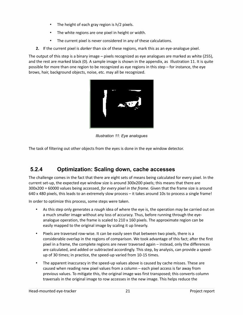
The output of this step is a binary image – pixels recognized as eye analogues are marked as white (255), and the rest are marked black (0). A sample image is shown in the appendix, as Illustration 11. It is quite possible for more than one region to be recognized as eye regions in this step – for instance, the eye brows, hair, background objects, noise, etc. may all be recognized.
The task of filtering out other objects from the eyes is done in the eye window detector.
5.2.4 Optimization: Scaling down, cache accessesThe challenge comes in the fact that there are eight sets of means being calculated for every pixel. In the current set-up, the expected eye window size is around 300x200 pixels; this means that there are 300x200 = 60000 values being accessed, for every pixel in the frame. Given that the frame size is around 640 x 480 pixels, this leads to an extremely slow process – it takes around 10s to process a single frame!
In order to optimize this process, some steps were taken.
• As this step only generates a rough idea of where the eye is, the operation may be carried out on a much smaller image without any loss of accuracy. Thus, before running through the eye-analogue operation, the frame is scaled to 210 x 160 pixels. The approximate region can be easily mapped to the original image by scaling it up linearly.
• Pixels are traversed row-wise. It can be easily seen that between two pixels, there is a considerable overlap in the regions of comparison. We took advantage of this fact; after the first pixel in a frame, the complete regions are never traversed again – instead, only the differences are calculated, and added or subtracted accordingly. This step, by analysis, can provide a speed-up of 30 times; in practice, the speed-up varied from 10-15 times.
• The apparent inaccuracy in the speed-up values above is caused by cache misses. These are caused when reading new pixel values from a column – each pixel access is far away from previous values. To mitigate this, the original image was first transposed; this converts column traversals in the original image to row accesses in the new image. This helps reduce the
Head-mounted eye-tracker 21 Project report
Illustration 11: Eye analogues

processing time by a factor of 3 or so.
The above optimization schemes allow the system to run at nearly 26 frames per second – an improvement of about 260 times over the first pass!
5.2.5 Eye window detectionThe eye-window detector receives as inputs the binary image representing eye analogue pixels. This node processes this image to reduce them to a single candidate for the eye.
The steps followed is given in Illustration 13. In brief, this step decomposes the binary image into objects ('blobs') composed of connected pixels. I used the open-source library, CVBlobs, to perform all operations on blobs. The initial set of blobs is filtered using parameters such as the expected height, width and orientation.
The figure below shows the output of this step for the sample images shown previously. As it can be seen, the filter has removed blobs corresponding to the eyebrows and hair, leaving only the eye in place.
The output of this node is the coordinates of the center of the eye region. This serves as an approximate estimate of the eye's location. Note that this does not say anything about the position of the eyeball; this merely serves as a reference for further processing.
The coordinates of the eye region are passed on to the next node, the Circle Hough Transform.
Assumptions
After blobs have been removed based on height, width and orientation, it is possible that the eyebrows, if present in the original image, are also retained. With this assumption, if more than one blobs are present, the lower one is taken as the eye region.
Head-mounted eye-tracker 22 Project report
Illustration 12: Single eye window

Head-mounted eye-tracker 23 Project report
Illustration 13: Reduction to single eye window
Perform connected-component labeling –
convert image to 'blobs'.
Remove blobs with width > 2w
Remove blobs with height > 2h
Remove blobs with width < w/4
Remove blobs with height < h/4
Remove blobs with orientation > 450.
Are there more than 1 blobs?
Take the second from top
Take center of bounding box of
blob
Scale up to original coordinates
Connected component labeling produces 'blobs' of pixels that are all connected to each other – each representing an object. An library based on OpenCV, CVBlobs, is used to operate on blobs.
Remove blobs that do not have the expected size, shape or orientation.
If there are more than one blobs left, it was seen that it is likely that the ones left correspond to the eyebrow and the eye. Assuming this, remove the top-most blob.
yesno
Calculate the approximate eye position, and scale up to original image size.
Send out coordinates

5.2.6 Pin-pointing the iris: Circle Hough TransformAt this point, the system has a rough idea of where the eye lies within the eye image. To perform accurate eye tracking, it is essential that the center of the iris be located. The tool used to perform this step is the Circle Hough Transform.
A Hough Transform is, essentially, a shape detector for edge images. It is widely used to detect straight lines and circles in edge images. Edge images are generated by running an edge detector, such as a Canny or a Sobel operator, over a gray-scale image. Edges correspond to points where there is an abrupt transition from bright to dark intensities.
A Circle Hough Transform detects circles of specified radii in edge images. The operation is as follows:
• At every edge point:
◦ A tangent is drawn.
◦ The perpendicular to the tangent is drawn.
◦ We move along the perpendicular, on both sides, to a distance corresponding to the required radius.
◦ The points reached each receive a vote.
• After all edge pixels have been processed, the pixels with a large number of votes correspond to circles of the required radius!
It is, of course, necessary to take into account factors like:
• No edge operator is perfect when there is noise; perfect circles are rarely encountered.
• It might be necessary to look at votes cumulatively around a pixel, rather than just at a single pixel.
Head-mounted eye-tracker 24 Project report

The greatest advantage of using a Hough transform is that it works even if the shape to be detected is partially hidden. In the current context, the iris, usually close to a circle, is almost always partially hidden by the eyelids. This makes the Hough Transform an attractive method to find the position of the iris.
The actual process is shown in Illustration 14.
A sample output, after the threshold step, is shown below.
The estimate of the eye position after the Circle Hough transform is shown below.
Head-mounted eye-tracker 25 Project report
Illustration 14: Applying circle Hough transform
Cut out the eye region
Threshold the image
Run the Canny edge operator
Run the Circle Hough Transform
Choose point with maximum votes as
iris center
Smoothen the estimate using previous values
A threshold is applied such that the iris is clearly differentiated from the rest of the image. Values greater than the threshold are set to it; those less than the threshold
are not altered. This prevents random circles being formed through noise.
In OpenCV, the edge operator and Hough transform are combined into a single call.
This again avoids random jumps of the eye estimate due to noise.
Illustration 15: Thresholded image

5.2.7 Composition and trackingThe final step in the eye tracking process is to translate the eye point calculated in the previous step into a corresponding point in the scene camera. This can be accomplished through straightforward linear interpolation:
snew=(enew−e) . scale+s
where
snew is the gaze point to be calculated
enew is the currently estimated eye-coordinate
scale is the factor by which the eye coordinate has to be scaled up
s is a known gaze point that corresponds to a known eye point e.
Note: snew and s are points on the scene video.
The challenge here is to accurately determine s,e and scale – i.e., to calibrate the device.
Once the scene point has been determined, a white bulls-eye is drawn on the scene video to represent the gaze point. A sample image is shown below. If the estimated position is outside the screen, a bulls-eye with only two circles is shown.
Head-mounted eye-tracker 26 Project report
Illustration 16: Estimage of the iris center

5.2.8 CalibrationThe compositor node operates in one of two modes:
• Tracking mode
Tracks the gaze point, as described above.
• Calibration mode
Calculates the parameters s,e and scale.
The calibration proceeds as follows:
• The 'known' points on the screen should correspond to the brightest point on the screen. In the calibration mode, this is shown as a black bulls-eye in the 'brightpoint' window. Illustration 18 shows the brightest point in the scene being denoted by a black bulls-eye (close to the right end of the scene).
Head-mounted eye-tracker 27 Project report
Illustration 17: Estimated gaze point

• It is recommended that a bright object, such as a powerful flashlight, be used. The calibration should ideally happen in a relatively dark environment.
• The bright object is positioned in two parts of the scene, s & s', ideally in diagonally opposite corners (the second point after the first point has been processed). The user is asked to look at these bright objects (without moving his/head), and the corresponding eye points, e & e' are recorded. The software simply finds the brightest point in the screen to find s and s'.
• The scale value is then calculated as:
scale=(s '−s )(e '−e)
Head-mounted eye-tracker 28 Project report
Illustration 18: Brightest point in the screen

5.3 Results and observations
5.3.1 SpeedAs described in Section 5.2.4 , significant optimization had to be carried out to ensure that the system performs in real-time. One measure of the speed is the throughput – the number of frames being processed per second (expressed as frames-per-second, fps). The system was measured to have a throughput of 26 fps, far exceeding our initial estimates!
Another measure is the latency. This is the time between when a particular input enters the system, and the corresponding output is seen. We have observed that the latency in this particular system is around 3 seconds.
5.3.2 AccuracyIt was seen that when properly calibrated, the eye tracker is able to estimate the gaze position with reasonable accuracy.
To test for accuracy, we adopted the bright-point method we used for calibration. The subject looks at the brightest point on the screen; during testing, we used a flashlight aimed at the camera for this purpose. The system runs a simple maximum operation to determine this point in the scene video. The gaze point estimate is then compared with this brightest point, and the error is determined in terms of pixels.
This experiment, of course, assumes that the subject is constantly staring at the brightest point in front of him, and that the system calculates the same point as the brightest!
A chart of the error calculated over one particular run is shown below.
Head-mounted eye-tracker 29 Project report

It can be seen that the mean error is estimated to be around 8% of the screen width.
A second run is shown below. It can be seen that in this case, the error estimated is higher, around 15%.
Head-mounted eye-tracker 30 Project report
Illustration 19: Error estimates, as a percentage of screen width
1 7 13 19 25 31 37 43 49 55 61 67 73 79 85 91 974 10 16 22 28 34 40 46 52 58 64 70 76 82 88 94 100
103106
109112
115118
121124
0
2
4
6
8
10
12
14
16
18
20E
rror
, as
perc
enta
ge o
f scr
een
wid
th

The accuracy is heavily dependent on several factors.
1. The calibration has to be accurate, in the first place. An incorrect calibration implies that the scale and offset values employed in transposing the eye position to the gaze position are wrong; this implies that the gaze position calculated will be in error.
Calibration in a lab environment is relatively easy – the lighting can be controlled very easily. However, outdoors, it will be difficult to have a specific bright point. A better mode might be to employ some form of pattern recognition, and use some patterns as the reference points on the scene.
2. The conditions under which the calibration has been performed has to be maintained throughout the tracking session. These conditions include:
a) The position of the hat must not slip. This will cause a large offset in the eye's position with respect to the camera; the eye may slip out of the region which is being processed.
b) The position of the scene camera must not change from what it was during calibration. This is self-explanatory; the scene points recorded will have an offset from the actual ones.
3. The connection from the eye camera to the hat is not rigid. It was intentionally kept flexible, to allow for easy adjustment of the camera. However, this leads to the camera vibrating – and that implies that the calibrated values may not be valid any more.
We have tried to compensate for this vibration by calculating the offsets and scale using the iris' position with respect to the eye window itself. A better approach would be to calculate the position of the eye corners, and track the eyeball with respect to the corners.
Head-mounted eye-tracker 31 Project report
Illustration 20: Error estimates, second run
0
5
10
15
20
25
30
35
40
45

4. Viewing angle of the scene camera
During testing, it was found that the viewing angle of the scene camera was extremely small – about 400 or so. This meant that any time the subject is squinting to one side, the view point would go out of bounds of the scene being recorded.
The solution, of course, would be to use a wide-angle camera; however, this will have to be balanced against the cost.
5.3.3 Cost: bill of materialsAn important challenge was to keep the costs as minimal as possible; the target was to keep the cost under $500. This has been met. The bill of materials is given below.
Sl No. Item Cost (USD)
1. Brickhouse Security Button Camera, 153-HC-BTNCM-W (Wired camera) 180
2. Boostervision GearCam, Item Number: BVGM-1 (Wireless camera) 70
3. Hauppauge Model 00610 "USB-Live2 “ RCA-USB convertor, 2 nos. 100
4. Hard hat 25
Total 375
Note: The cost of a PC is not included in the above, as it is a generic unit that is easily available in any lab.
5.3.4 Requirements match
Tag Status Comments
[SYS-01] Met A head-mounted unit has been designed.
[SYS-02] Met A base station has been designed.
[SYS-03] Met The data transfer is currently a combination of wireless and wired links.
[SYS-04] Met The eye tracker shows the output in a window in the screen.
[SYS-05] Partially met A rough estimate of the eye position is calculated.
[SYS-06] Met See note for SYS-05.
[SYS-07] Met The Eye Tracker system shall take as input the field of view of a subject.
[SYS-08] Met The Eye Tracker system shall output the focus of the subject's gaze.
[SYS-07] Met The latency of the system is around 3s.
[SYS-08] Unknown The accuracy has not been measured.
[SYS-09] Met See bill of materials.
Head-mounted eye-tracker 32 Project report

[SYS-10] Not met The head-mounted unit currently includes one wired camera. However, it can be easily replaced with a wireless one.
[HMU-01] Met
[HMU-02] Not met The processing involved reduces the frame rate to about 15fps.
[HMU-03] Not met The camera being used capture video of size 640 x 480.
[HMU-04] Met
[HMU-05] Not met See comment for HMU-02.
[HMU-06] Met
[HMU-07] Met The signal is transmitted as a video signal.
[HMU-08] Not met See SYS-10.
[HMU-09] Met
[BASE-01] Met
[BASE-02] Met
[BASE-03] Met
[BASE-04] Met
[BASE-05] Met
[BASE-06] Not met The option causes the system to become unstable; issue seems to be with underlying OpenCV framework. Works in debug mode at 2fps.
[BASE-07] Met
[TXF-01] Met The Data Transfer Sub-system (DTSS) shall transmit the field of view video signal to the Base Station.
[TXF-02] Met The DTSS shall transmit the gaze focus signal to the Base Station.
[TXF-03] Not met See comment for SYS-01.
[TXF-04] Met A 2.4 GHz wireless interface is used.
[VOUT-01] Met
[VOUT-02] Met The video is limited by the input rate.
[VOUT-03] Met The video size is limited by the input video feed.
Head-mounted eye-tracker 33 Project report

6 ConclusionWe put together a system that can locate the point of view of a person's gaze using a video feed of his/her eye movements. The unit consists of a head-mounted unit with wireless/wired cameras, and a base station capable of processing the video signals. We explored both offline and real-time analysis of the video. The performance and issues encountered with these methods have been listed above.
7 References
[1] Efficient face candidates selector for face detection, Jianxin Wu , Zhi-Hua Zhou, 2001National Laboratory for Novel Software Technology, Nanjing University
[2] The OpenEyes eye tracking project, at http://thirtysixthspan.com/openEyes/
[3] The OpenCV project, at http://opencv.willowgarage.com/wiki/
[4] The CVBlobls project, at http://opencv.willowgarage.com/wiki/cvBlobsLib
Head-mounted eye-tracker 34 Project report