headend products - imageeventphotos.imageevent.com/koshmeister/electronics/headend.pdf ·...
TRANSCRIPT

Headend Products
Commercial Satellite ReceiverCommercial Digital Satellite Receiver
Broadcast Frequency Locked ModulatorAgile Audio/Video Modulators
Triple Channel Agile Audio/Video ModulatorsChannelized Agile Audio/Video Modulators
Modular Headend SystemHeterodyne Processors
Agile Audio/Video Demodulator - StereoActive Combiners
Strip Amplifi ersChannel Converters
Bandpass FiltersChannel Elimination Filters
Tunable Notch TrapsChannelized Audio/Video Modulators
Agile Audio/Video DemodulatorCombiners
Channel ConvertersFM Strip Amplifi ers
Agile FM Stereo ModulatorProfessional Agile Modulators
Headend Racks and PanelsVideo All-Call Systems
IF Demodulator/Modulator
Hea
den
d

Head
end
Headend
MQQT
AP
OC
RMDA
Distribution
QT Series
The Headend is the heart of Cable TV system (whether the signals are analog or digital). It handles many functions including reception and processing of broadcast or “off-air” television signals and reception, decryption and modulation of satellite delivered programming in preparation for distribution to cable television subscribers.
The broadcast signals routed to the headend are filtered to reject any unwanted signals from adjacent off-air channels and adjusted for proper aural & visual carrier levels in. They can be fed to a signal processor or a demodulator / modulator approach can also be used.
The majority of Cable TV channels are delivered to the headend via satellite. In this method signals are uplinked to a communications satellite in geosynchronous orbit from an uplink facility. The satellite then retransmits the signal back to earth where it is received by dish shaped antennas which focus the signals. At the dish, an LNB (low noise block converter) amplifies the signals and delivers them to the headend via a coaxial cable. Most satellite signals are scrambled and the satellite receiver in the headend is used to decode the signals. These units may have the ability to decode or decrypt the scrambling of a particular format or type of signal built in (IRD). The satellite receiver typically converts the signal to a baseband audio & video signal. This signal is then modulated onto any desired CATV channel.
Headend Products Overview
www.blondertongue.com • 800-523-6049 30
Features & Benefits
• Blonder Tongue Headend Products Feature Superior Performance at Affordable Prices
• All Products Exceed FCC CATV Specifications and Typically Meet FCC Broadcast Specifications
• Commercial Quality Equipment Provides Exceptional Picture Quality
• High CNR/SNR Performance Permits Large Multi-Channel Headends, Even with Agile Units
The CATV headend uses frequency division multiplexing to combine signals from broadcast TV processors, satellite fed modulators and locally originated system specific channels onto a single feed. The combining process is passive since the signals already occupy discrete frequencies and have been adjusted to the same RF carrier level by their respective processing equipment. Passive combiners simply provide multiple signal ports where different signals are connected and are combined onto a single output containing all of the input signals. A post amplifier, sometimes called a launch or distribution amplifier, then amplifies the signals and provides slope control so that the entire range of carriers can be at the correct RF level for launching to the distribution system.
Headend Digital Tier (also see Digital Products Section)
Application Diagram

Hea
den
d
Headend Products Overview
OC Combiner
MAVM
RMDA
Converter(Baseband Output)
CAP or SAIP
Alternative Method
MIDM or MICM
CATVInput
CDSR-6198 IRD-6185
OC
RMDA
CAP or SAIP
Distribution
CAM or MAVM
www.blondertongue.com • 800-523-604931
Small System Headend
Cherry Picker Headend
Head
end
Specifications
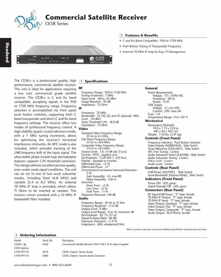
• C and Ku Band Compatible - 950 to 1750 MHz
• Push Button Tuning of Transponder Frequency
• External 70 MHz IF loop for Easy TI Management
Commercial Satellite Receiver CESR Series
The CESR-c is a professional quality, high performance, commercial satellite receiver. This unit is ideal for applications requiring a low cost, commercial grade satellite receiver. The CESR-c is C and Ku band compatible, accepting signals in the 950 to 1750 MHz frequency range. Frequency selection is accomplished via front panel push button switches, supporting both C band transponder and direct C and Ku band frequency settings. The receiver offers two modes of synthesized frequency control. A high-stability quartz crystal reference mode, with a 1 MHz tuning increment, allows for optimizing the receiver’s terrestrial interference immunity. An AFC mode is also included, which provides tracking of the LNB frequency drift of the input signal. The ultra-stable phase locked loop demodulator features superior C/N threshold extension. This design delivers excellent picture quality, even under weak signal conditions. The unit can be set to one of two aural subcarrier modes, including fixed (6.8 MHz) and variable (5.4 to 8.2 MHz). An external 70 MHz IF loop is provided, which allows TI filters to be inserted as needed. This receiver comes standard with a 32 MHz IF bandwidth filter installed.
RFFrequency Range: 950 to 1750 MHzTuning Increment: 1 MHzInput Level: -60 to -25 dBmImage Rejection: 45 dBImpedance: 75 Ohm
IFFrequency: 70 MHzBandwidth: 32 (18, 20, and 25 optional) MHzLevel: -10 dBmStatic Threshold C/N: <8.0 dBImpedance: 75 Ohm
VideoStandard Video Frequency Range: 25 Hz to 4.2 MHzFlat Video Frequency Range: 25 Hz to >8.0 MHzComposite Video Frequency Range: 25 Hz to >8.0 MHzOutput Level: 1.0, ±3 dB adj. (V p-p)Format: NTSC, negative syncDe-Emphasis: CCIR 405-1, 525 linesPolarity: standard or invertedDifferential Gain: <5 % Differential Phase: <5 °Chrominance/Luminance Intermod Distortion: 3 % Gain Inequality: ±5, max IRE Delay Inequality: ±26 nsDistortion Short Time: <3 % Line Time: <2 % Field Time: <3 % Dispersion Removal: >40 dB
AudioFrequency Range: 20 Hz to 15 kHzFrequency Response: ±1.0 dBOutput Level: 0 dBmOutput Level Range: 0 to 12, minimum dBDe-Emphasis: 50, 75, J17 µsSignal-to-Noise Ratio: 60 dBHarmonic Distortion: <1.0 %Impedance: 600, unbalanced Ohm
GeneralPower Requirements Voltage: 117, ±10% VAC Frequency: 60 Hz Power: 15 WLNB Supply Voltage: 17, min VDC Current: 250, max mAFuse: 1/4Temperature Range: 0 to +50 °C
MechanicalDimensions (WxHxD): 19.0 x 1.75 x 12.0 in. 483 x 44 x 305 mmWeight: 7.50 lbs. (3.41 kg)
Controls (Front Panel)Frequency Selection: Push Button SwitchesVideo Polarity (NORM/INV): Slide SwitchTuner Reference (XTAL/AFC): Slide SwitchAFC Fine Tuning: ControlAudio Subcarrier Select (6.8/VAR): Slide SwitchAudio Subcarrier Tuning: ControlVideo Level: ControlAudio Level: Control
Controls (Rear Panel)LNB Power (ON/OFF): Slide SwitchAural Bandwidth (Narrow/Wide): Slide Switch
Indicators (Front Panel)Power ON: LED, greenSignal Strength OK: LED, green
Connectors (Rear Panel)RF Input/LNB Power: "F" type, female70 MHz IF Output: "F" type, female70 MHz IF Input: "F" type, femaleVideo Output, Standard: "F" type, femaleVideo Output, Flat: "F" type, femaleVideo Output, Composite: "F" type, femaleAudio Output: RCA Phono, female
Ordering InformationModel Stock No. DescriptionCESR-C 6166 Commercial Satellite Receiver 950-1750 C & Ku Band Capable CESR OptionsCESR-OPT 02 6470 CESR-c Option: Stereo Audio CESR-OPT 03 6480 CESR-c Option: Second Audio Subcarrier
www.blondertongue.com • 800-523-6049 32
Refer to product instruction manual for additional specification measurements and notes.
Features & Benefits

Hea
den
d
www.blondertongue.com • 800-523-604933
Features & Benefits
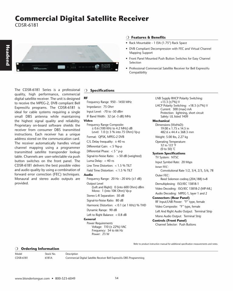
• Rack Mountable - 1 EIA (1.75") Rack Space
• DVB Compliant Decompression with FEC and Virtual Channel Mapping Support
• Front Panel Mounted Push Button Switches for Easy Channel Selection
• Professional Commercial Satellite Receiver for EchoStar Dish Network Compatibility
Specifications
Ordering Information
The CDSR-6198 is a professional quality, high performance, commercial digital satellite receiver. The unit is designed to receive MPEG-2, DVB compliant DISH Network™ programs. The CDSR-6198 is ideal for cable systems requiring a single small DBS antenna while maintaining the highest signal quality and reliability. The best possible video and audio quality is delivered by using a combination of forward error correction (FEC) techniques.
Each receiver has a unique address stored on the communication card. The receiver automatically handles virtual channel mapping using a programmer transmitted satellite transponder lookup table. Channels are user-selectable via push button switch on the front panel. Monaural and stereo audio outputs are provided.
RFFrequency Range: 950 - 1450 MHzImpedance: 75 OhmInput Level: -70 to -30 dBmIF Band Width: 32 (at -3 dB) MHz
VideoFrequency Range Composite: ± 0.6 (100 KHz to 4.2 MHz) dBLevel: 1.0 (± 3 % into 75 Ohm) Vp-pFormat: QPSK, MPEG-2 DVBC/L Delay Inequality: ± 40 nsDifferential Gain: < 3 % p-pDifferential Phase: < 3 ° p-pSignal-to-Noise Ratio: > 55 dB (weighted)Luma Delay: < 40 nsLine Time Distortion: < 1.5 % TILTField Time Distortion: < 1.5 % TILT
AudioFrequency Range: 20 Hz - 20 kHz (±1 dB)Output Level (Left and Right): 0 (into 600 Ω) dBm Mono: 1 (into 10K Ω) Vp-pStereo L-R Separation: 50 dBSignal-to-Noise Ratio: 80 dBHarmonic Distortion: < 0.1 (at 1 KHz) % THDDynamic Range: 90 dBLeft to Right Balance: < 0.8 dB
GeneralPower Requirements Voltage: 110 (± 22%) VAC Frequency: 54 to 66 Hz Power: 23 W
LNB Supply RHCP Polarity Switching: +13.3 (±7%) VLHCP Polarity Switching: +18.3 (±7%) VCurrent: 300 (max) mAProtection: Lightning, short circuitSafety: UL listed 1409
MechanicalDimensions (WxHxD): 19.00 x 1.75 x 14.5 in 482.6 x 44.4 x 368.3 mmWeight: 5.00 lbs, 2.27 kgOperating Temperature: 32 to 122 ˚F, (0 to 50) ° C
System SpecificationsTV System: NTSCInput Symbol Rate: 20 MspsInner FEC: Convolutional Rate 3/4Outer FEC: Reed Solomon coding (204,188) t=8Demultiplexing: ISO/IEC 13818-1Video Decoding: ISO/IEC 13818-2 (MP-ML)Audio Decoding: MPEG 1, layer 1 and 2
Connectors (Rear Panel)RF Input/LNB Power: “F” type, femaleVideo Composite: “F” type, femaleLeft And Right Audio Output: Terminal StripMono Audio Output: Terminal Strip
Controls (Front Panel)Channel Selector: Push Buttons
Model Stock No. DescriptionCDSR-6198A 6198A Commercial Digital Satellite Receiver Dish Network DBS Programming
Refer to product instruction manual for additional specification measurements and notes.
Head
end
www.blondertongue.com • 800-523-6049 34
Features & Benefits
Commercial Digital Satellite Receiver CDSR-6181
Specifications The CDSR-6181 Series is a professional quality, high performance, commercial digital satellite receiver. The unit is designed to receive the MPEG-2, DVB compliant Bell ExpressVu programs. The CDSR-6181 is ideal for cable systems requiring a single small DBS antenna while maintaining the highest signal quality and reliability. Proprietary on-board software shields the receiver from consumer DBS transmitted instructions. Each receiver has a unique address stored on the communication card. The receiver automatically handles virtual channel mapping using a programmer transmitted satellite transponder lookup table. Channels are user-selectable via push button switches on the front panel. The CDSR-6181 delivers the best possible video and audio quality by using a combination of forward error correction (FEC) techniques. Monaural and stereo audio outputs are provided.
RFFrequency Range 950 - 1450 MHzImpedance: 75 OhmInput Level: -70 to -30 dBmIF Band Width: 32 (at -3 dB) MHz
VideoFrequency Range Composite: ± 0.6 (100 KHz to 4.2 MHz) dB Level: 1.0 (± 3 % into 75 Ohm) Vp-pFormat: QPSK, MPEG-2 DVBC/L Delay Inequality: ± 40 nsDifferential Gain: < 5 %p-pDifferential Phase: < 5 ° p-pSignal-to-Noise Ratio: > 50 dB (weighted)Luma Delay: < 40 nsLine Time Distortion: < 1.5 % TILTField Time Distortion: < 1.5 % TILT
AudioFrequency Range: 20 Hz - 20 kHz (±1 dB)Output Level (Left and Right): 0 (into 600 Ohm) dBm Mono: 1 (into 10K Ohm) Vp-pStereo L-R Separation: 50 dBSignal-to-Noise Ratio: 80 dBHarmonic Distortion: < 0.1 (at 1 KHz) % THDDynamic Range: 90 dBLeft to Right Balance: < 0.8 dB
GeneralPower Requirements Voltage: 110 (± 22%) VAC Frequency: 54 to 66 Hz Power: 23 W
LNB Supply RHCP Polarity Switching: +13.3 (±7%) VLHCP Polarity Switching: +18.3 (±7%) V Current: 300 (max) mA Protection: lightning, short circuit Safety: UL listed 1409
MechanicalDimensions (WxHxD): 19.00 x 1.75 x 14.5 in 482.6 x 44.4 x 368.3 mmWeight: 5.00 lbs, 2.27 kgOperating Temperature: 32 to 122 ˚F (0 to 50) ˚C
System SpecificationsTV System: NTSCInput Symbol Rate: 20 MspsInner FEC: Convolutional Rate 1/2, 3/4, 2/3, 5/6, 78Outer FEC: Reed Solomon coding (204,188) t=8Demultiplexing: ISO/IEC 13818-1Video Decoding: ISO/IEC 13818-2 (MP-ML)Audio Decoding: MPEG 1, layer 1 and 2
Connectors (Rear Panel)RF Input/LNB Power: “F” type, femaleVideo Composite: “F” type, femaleLeft And Right Audio Output: Terminal StripMono Audio Output: Terminal Strip
Controls (Front Panel)Channel Selector: Push Buttons
Ordering InformationModel Stock No. DescriptionCDSR-6181 6181A Commercial Digital Satellite Receiver Bell ExpressVu DBS Programming
Refer to product instruction manual for additional specification measurements and notes.
• Rack Mountable - 1 EIA (1.75") Rack Space
• DVB Compliant Decompression with FEC and Virtual Channel Mapping Support
• Front Panel Mounted Push Button Switches for Easy Channel Selection
• Professional Commercial Satellite Receiver for Bell ExpressVu Compatibility
Hea
den
d
www.blondertongue.com • 800-523-604935
Features & Benefits
Commercial Digital Satellite Receiver CDSR-6199
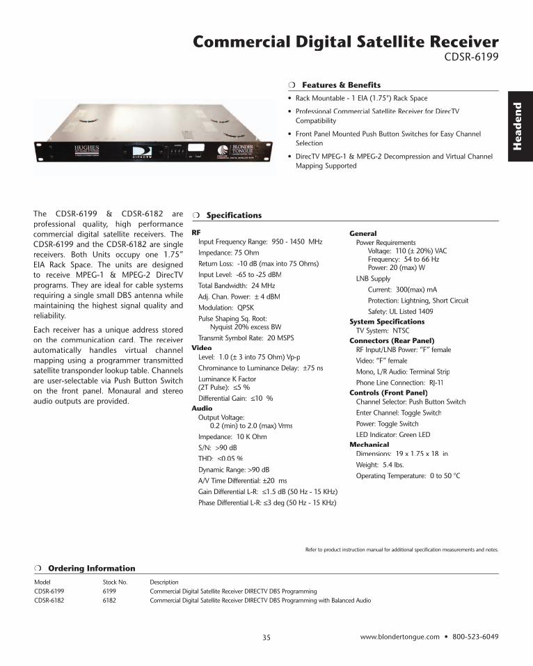
• Rack Mountable - 1 EIA (1.75") Rack Space
• Professional Commercial Satellite Receiver for DirecTV Compatibility
• Front Panel Mounted Push Button Switches for Easy Channel Selection
• DirecTV MPEG-1 & MPEG-2 Decompression and Virtual Channel Mapping Supported
Specifications
Ordering Information
The CDSR-6199 & CDSR-6182 are professional quality, high performance commercial digital satellite receivers. The CDSR-6199 and the CDSR-6182 are single receivers. Both Units occupy one 1.75” EIA Rack Space. The units are designed to receive MPEG-1 & MPEG-2 DirecTV programs. They are ideal for cable systems requiring a single small DBS antenna while maintaining the highest signal quality and reliability.
Each receiver has a unique address stored on the communication card. The receiver automatically handles virtual channel mapping using a programmer transmitted satellite transponder lookup table. Channels are user-selectable via Push Button Switch on the front panel. Monaural and stereo audio outputs are provided.
RFInput Frequency Range: 950 - 1450 MHzImpedance: 75 OhmReturn Loss: -10 dB (max into 75 Ohms)Input Level: -65 to -25 dBMTotal Bandwidth: 24 MHzAdj. Chan. Power: ± 4 dBMModulation: QPSKPulse Shaping Sq. Root: Nyquist 20% excess BWTransmit Symbol Rate: 20 MSPS
VideoLevel: 1.0 (± 3 into 75 Ohm) Vp-pChrominance to Luminance Delay: ±75 nsLuminance K Factor(2T Pulse): ≤5 %Differential Gain: ≤10 %
AudioOutput Voltage: 0.2 (min) to 2.0 (max) VrmsImpedance: 10 K OhmS/N: >90 dBTHD: ≤0.05 %Dynamic Range: >90 dBA/V Time Differential: ±20 msGain Differential L-R: ≤1.5 dB (50 Hz - 15 KHz)Phase Differential L-R: ≤3 deg (50 Hz - 15 KHz)
GeneralPower Requirements Voltage: 110 (± 20%) VAC Frequency: 54 to 66 Hz Power: 20 (max) WLNB Supply Current: 300(max) mA Protection: Lightning, Short Circuit Safety: UL Listed 1409
System SpecificationsTV System: NTSC
Connectors (Rear Panel)RF Input/LNB Power: “F” femaleVideo: “F” femaleMono, L/R Audio: Terminal StripPhone Line Connection: RJ-11
Controls (Front Panel)Channel Selector: Push Button SwitchEnter Channel: Toggle SwitchPower: Toggle SwitchLED Indicator: Green LED
Mechanical Dimensions: 19 x 1.75 x 18 in.Weight: 5.4 lbs.Operating Temperature: 0 to 50 °C
Model Stock No. DescriptionCDSR-6199 6199 Commercial Digital Satellite Receiver DIRECTV DBS Programming CDSR-6182 6182 Commercial Digital Satellite Receiver DIRECTV DBS Programming with Balanced Audio
Refer to product instruction manual for additional specification measurements and notes.
Head
end
Specifications
Ordering Information
Features & Benefits
Broadcast Frequency Locked Modulator BFLM System
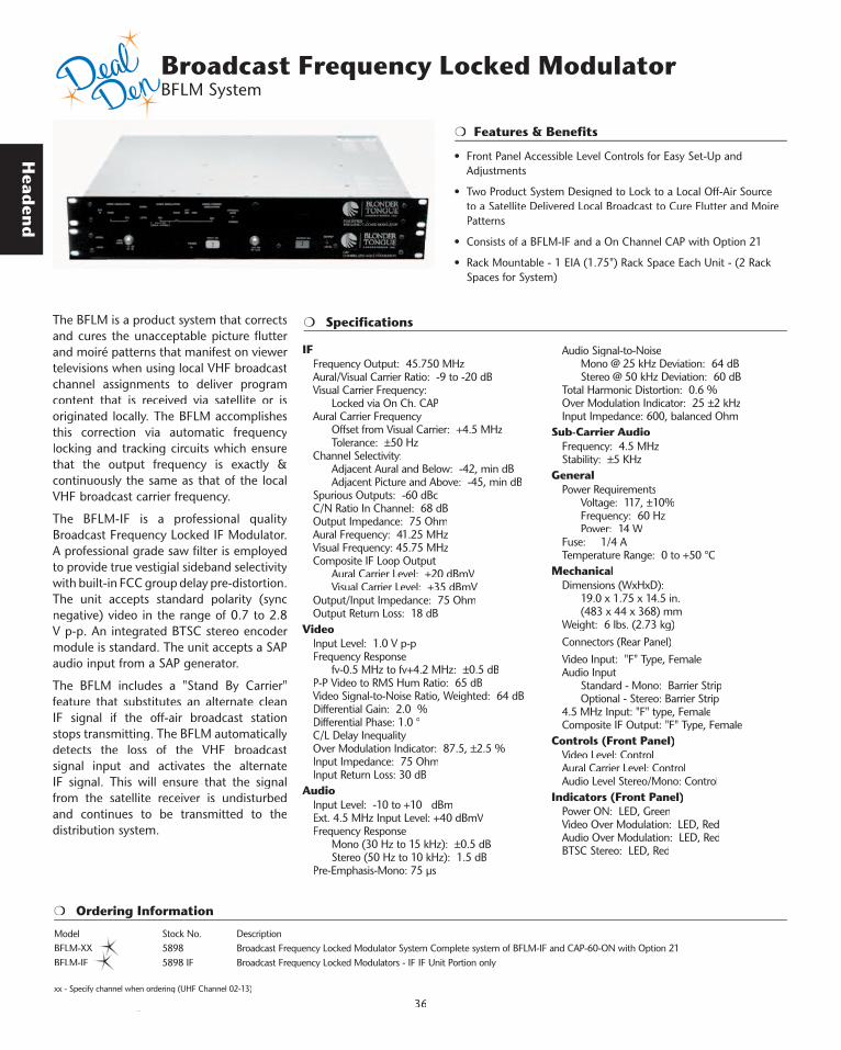
The BFLM is a product system that corrects and cures the unacceptable picture flutter and moiré patterns that manifest on viewer televisions when using local VHF broadcast channel assignments to deliver program content that is received via satellite or is originated locally. The BFLM accomplishes this correction via automatic frequency locking and tracking circuits which ensure that the output frequency is exactly & continuously the same as that of the local VHF broadcast carrier frequency.
The BFLM-IF is a professional quality Broadcast Frequency Locked IF Modulator. A professional grade saw filter is employed to provide true vestigial sideband selectivity with built-in FCC group delay pre-distortion. The unit accepts standard polarity (sync negative) video in the range of 0.7 to 2.8 V p-p. An integrated BTSC stereo encoder module is standard. The unit accepts a SAP audio input from a SAP generator.
The BFLM includes a "Stand By Carrier" feature that substitutes an alternate clean IF signal if the off-air broadcast station stops transmitting. The BFLM automatically detects the loss of the VHF broadcast signal input and activates the alternate IF signal. This will ensure that the signal from the satellite receiver is undisturbed and continues to be transmitted to the distribution system.
IF Frequency Output: 45.750 MHz Aural/Visual Carrier Ratio: -9 to -20 dBVisual Carrier Frequency: Locked via On Ch. CAPAural Carrier Frequency Offset from Visual Carrier: +4.5 MHz Tolerance: ±50 HzChannel Selectivity: Adjacent Aural and Below: -42, min dB Adjacent Picture and Above: -45, min dBSpurious Outputs: -60 dBcC/N Ratio In Channel: 68 dBOutput Impedance: 75 OhmAural Frequency: 41.25 MHzVisual Frequency: 45.75 MHzComposite IF Loop Output Aural Carrier Level: +20 dBmV Visual Carrier Level: +35 dBmVOutput/Input Impedance: 75 OhmOutput Return Loss: 18 dB
VideoInput Level: 1.0 V p-pFrequency Response fv-0.5 MHz to fv+4.2 MHz: ±0.5 dBP-P Video to RMS Hum Ratio: 65 dBVideo Signal-to-Noise Ratio, Weighted: 64 dBDifferential Gain: 2.0 %Differential Phase: 1.0 °C/L Delay InequalityOver Modulation Indicator: 87.5, ±2.5 %Input Impedance: 75 OhmInput Return Loss: 30 dB
AudioInput Level: -10 to +10 dBmExt. 4.5 MHz Input Level: +40 dBmVFrequency Response Mono (30 Hz to 15 kHz): ±0.5 dB Stereo (50 Hz to 10 kHz): 1.5 dBPre-Emphasis-Mono: 75 µs
Audio Signal-to-Noise Mono @ 25 kHz Deviation: 64 dB Stereo @ 50 kHz Deviation: 60 dBTotal Harmonic Distortion: 0.6 %Over Modulation Indicator: 25 ±2 kHzInput Impedance: 600, balanced Ohm
Sub-Carrier AudioFrequency: 4.5 MHzStability: ±5 KHz
GeneralPower Requirements Voltage: 117, ±10% Frequency: 60 Hz Power: 14 W Fuse: 1/4 ATemperature Range: 0 to +50 °C
MechanicalDimensions (WxHxD): 19.0 x 1.75 x 14.5 in. (483 x 44 x 368) mmWeight: 6 lbs. (2.73 kg)Connectors (Rear Panel)Video Input: "F" Type, FemaleAudio Input Standard - Mono: Barrier Strip Optional - Stereo: Barrier Strip4.5 MHz Input: "F" type, FemaleComposite IF Output: "F" Type, Female
Controls (Front Panel)Video Level: ControlAural Carrier Level: ControlAudio Level Stereo/Mono: Control
Indicators (Front Panel)Power ON: LED, GreenVideo Over Modulation: LED, RedAudio Over Modulation: LED, RedBTSC Stereo: LED, Red
Model Stock No. DescriptionBFLM-XX 5898 Broadcast Frequency Locked Modulator System Complete system of BFLM-IF and CAP-60-ON with Option 21 BFLM-IF 5898 IF Broadcast Frequency Locked Modulators - IF IF Unit Portion only
www.blondertongue.com • 800-523-6049 36xx - Specify channel when ordering (UHF Channel 02-13)
• Front Panel Accessible Level Controls for Easy Set-Up and Adjustments
• Two Product System Designed to Lock to a Local Off-Air Source to a Satellite Delivered Local Broadcast to Cure Flutter and Moire Patterns
• Consists of a BFLM-IF and a On Channel CAP with Option 21
• Rack Mountable - 1 EIA (1.75") Rack Space Each Unit - (2 Rack Spaces for System)
Hea
den
d
www.blondertongue.com • 800-523-604937
Features & Benefits
Agile Audio/Video Modulators AM-60-860 Series
The AM-60-860 is a professional quality agile audio/video modulator. It is equipped with the Emergency Alert System (EAS) feature, which can also be used as an alternate IF input. The unit provides an audio and video modulated RF carrier on any channel from 54 to 860 MHz. Any standard audio/video source can be used, such as satellite receivers, television cameras, video tape recorders, or television demodulators.
Channel tuning is easily accomplished with the use of front panel push button switches. Frequency plans including CATV Standard EIA, IRC, HRC & Broadcast are available in the 54-860 MHz frequency range. All channel frequency information with appropriate FCC offsets is pre-programmed and tuned electronically via microprocessor.
The unit has a wide range of standard and optional features that make it ideal for advanced CATV systems. 4.5 MHz aural input, and 600 Ohm balanced audio have been incorporated as standard equipment on the AM-60-860. A stereo audio option, Option 05, allows the integration of a BTSC stereo encoder module. This optional stereo encoder converts stereo left and right audio into a composite BTSC stereo audio signal. The factory installed option provides 20 dB of stereo separation, less than 1.0% total harmonic distortion and 60 dB signal to noise ratio.
• Supports All Broadcast and CATV Channels, Including All HRC and IRC Assignments
• EAS/ALT IF Ready Via Manual or Automatic Mode
• Superior Broadband Noise Performance (-76 dB)
• Fully Compatible With BTSC Encoded Stereo Audio
• All Level Controls are Conveniently Located on Front Panel For Easy Set Up and Adjustment
• Rack Mountable - 1 EIA (1.75") Rack Space
• Balanced Audio Input Standard
The AM-60-860 meets FCC Docket 21006 aeronautical frequency offset requirements (±5 kHz video carrier accuracy). Outstanding in channel carrier to noise performance of 67 dB typical is achieved by the unit. A custom SAW IF filter is employed to provide true vestigial sideband selectivity with built-in FCC group delay equalization. A state of the art converter design with preprogrammed microprocessor controlled channel tuning @ 60 dBmV output ensures the Blonder Tongue AM-60-860 is the ideal agile modulator for any demanding CATV headend need.
Specifications and Ordering Information are located on the following pages.
Head
end
www.blondertongue.com • 800-523-6049 38
Agile Audio/Video Modulators AM-60-860 Series
Specifications
Ordering Information
RFFrequency Range: 54-860 MHzChannels: CATV, VHF, UHF (STD,HRC,IRC)FCC Offset (pre-programmed): 0, +12.5, or 25 kHzOutput Level - Min: +60 dBmVOutput Level Adjust: 10 dBAural/Visual Carrier Ratio: -15 ±5 dBVisual Carrier Frequency Tolerance Standard Channels: ±10 kHz FCC Aeronautical Channels: ±5 max kHz4.5 MHz Aural Inter Carrier Frequency: ±150HzChannel Selectivity: Adjacent Aural and Below: -40 dB Adjacent Picture and Above: -50 dBSpurious Outputs: -60 dBcC/N Ratio In Channel: 67 dBBroadband Noise: -80 dBcOutput Impedance: 75 OhmOutput Return Loss: 14 dB
IFAural Frequency Standard: 41.25 MHzVisual Frequency Standard: 45.75 MHzComposite IF Loop Output Aural Carrier Level: +20 dBmV Visual Carrier Level: +35 dBmVOutput/Input Impedance: 75 OhmOutput Return Loss: 16 dBInput Return Loss: 20 dBEAS/ALT IF Input Level: 36 dBmV @ 45.75 MHzEAS/ALT IF Switch Isolation: >60 dB
VideoInput Level: 1.0 V p-pFrequency Response fv-0.5 MHz to fv+4.2 MHz: ±1.0 dBP-P Video to RMS Hum Ratio: 65 dBVideo Signal-to-Noise Ratio, Weighted: 64 dBDifferential Gain: 2.0 %Differential Phase: 1.0 °Over Modulation Indicator: 87.5, ±2.5 %Input Impedance: 75 OhmInput Return Loss: 18 dB
AudioInput Level: 140 mV RMSExt. 4.5 MHz Input Level: +35 to +45 dBmVFrequency Range: 20 Hz to 20 kHzFrequency Response: ±1.0 dBPre-Emphasis-Mono: 75 µsAudio Signal-to-Noise: 60 dBTotal Harmonic Distortion: 0.6 %Over Modulation Indicator : 25, ±2 kHzInput Impedance: 600, balanced Ohm
GeneralPower Requirements Voltage: 117, ±10% VAC Frequency: 60 Hz Power: 25 WFuse: 0.40 ATemperature Range: 0 to +50 °C
MechanicalDimensions (WxHxD): 19.0 x 1.75 x 14.5 in 483 x 44 x 368 mmWeight: 7 lbs. (3.18 kg)
Connectors (Rear Panel)Video Input Standard: "F" type, femaleOption 02: BNC Video Input: BNC type, femaleOption 10: Composite A/V: "F" type, femaleAudio Input: Barrier StripComposite Video/Audio Input Option 10: "F" type, femaleIF Output: "F" type, femaleIF Input: "F" type, femaleRF Output: "F" type, femaleEAS/ALT IF: "F" type, female
Controls (Front Panel)Frequency Selection: Push-Button SwitchesVideo Level: ControlAural Carrier Level: ControlAudio Level: ControlRF Output Level: Control
Indicators (Front Panel)Power ON: LED, greenVideo Over Modulation: LED, redAudio Over Modulation: LED, redEAS/ALT IF: LED, green
Model Stock No. DescriptionAM-60-860 59415 Agile Audio/Video Modulator +60 dBmV, 54-860 MHz with EAS Feature OptionsModel Stock No. DescriptionAM-OPT 02 5902 AM Series Option: Video Input, BNC Connector AM-OPT 04 5904 AM Series Option: Sub-Band Output AM-OPT 05 5905 AM Series Option: Integrated BTSC Stereo Audio AM-OPT 07 5907 AM Series Option: Video AGC AM-OPT 10 5910 AM Series Option: Composite Video & 4.5 MHz Audio Input (Not all options/combinations are available)
Refer to product instruction manual for additional specification measurements and notes.

Hea
den
d
www.blondertongue.com • 800-523-604939
Agile Audio/Video Modulators AM-550/750 Series
Features & Benefits
The AM-550/750 Series are professional quality, agile audio/video modulators. They are equipped with the Emergency Alert System (EAS) feature, which can also be used as an alternate IF input. These units provide audio and video modulated RF carrier on any channel in 54 to 550/750 MHz frequency range. The AM Series is ideal for placing audio and video onto any unused channel (broadcast CATV, including HRC and IRC assignments). Any standard audio/video source can be used, such as satellite receivers, television cameras, video tape recorders, or television demodulators.
Agile channel selection permits on-the-fly channel changes and reduces the need for large inventories of channelized products. Channel selection is accomplished with the use of simple to use front panel accessible dip switches.
These modulators have a wide range of standard and optional features that make them very suitable for advanced CATV systems. Four models are available with different output levels, frequency ranges and a variety of options.
• Supports All Broadcast and CATV Channels, Including All HRC and IRC Assignments
• EAS/ALT IF Ready Via Manual or Automatic Mode
• Superior Broadband Noise Performance (-76 dB)
• Fully Compatible With BTSC Encoded Stereo Audio
• Rack Mountable - 1 EIA (1.75") Rack Space
All models feature rock solid, synthesized frequency control, with a tuning increment of 250 kHz. A custom SAW filter is employed to provide true vestigial sideband selectivity with built-in FCC group delay pre-distortion. These modulators have an external IF loop, which allows interfacing with video all-call and signal scrambling systems. The EAS Alternate IF feature allows the choice between manual and automatic selection of EAS/ALT IF input signal. This is done through a 3 position terminal strip on the rear of the unit.
The AM Series meets FCC Docket 21006 aeronautical frequency offset requirements (±5 kHz video carrier accuracy). These modulators provide extremely clean output signals with distortion products (-60 dB or better). An exceptionally low broadband noise floor (-76 dBc or better) makes the AM Series ideal for large, multiple channel headends without the need for additional filtering.
Specifications and Ordering Information are located on the following pages.
Head
end
www.blondertongue.com • 800-523-6049 40
Agile Audio/Video Modulators AM-550/750 Series
Specifications
Ordering Information
RFOutput Frequency Range AM xx-550B Ch. 2 to Ch. 78: 54 - 547.25 MHz AM xx-750B Ch. 2 to Ch. 116: 54 - 745.25 MHzOutput Level AM 40-xxxB: +42 dBmV AM 60-xxxB: +60 dBmVOutput Level Control Range Continuously Adjustable AM 40-xxxB: 32 to 42 dBmV AM 60-xxxB: 50 to 60 dBmVAural/Visual Carrier Ratio Control: -12 to -18 dB (Continuously Adjustable Factory Set to -15 dB)Visual Carrier Frequency Tolerance Standard Channels: ±20 KHz Aeronautical Channels: ±5.0 KHz4.5 MHz Inter Carrier Frequency Tolerance: ±300 HzChannel Passband Response fv -0.5 to fv +4.2 MHz: +1 dBVSB Response fv -1.50 MHz: -38 dB, lower channel aural fv -2.42 MHz: -40 dB, lower channel color fv -3.58 MHz: -40 dB, color carrier image fv -6.00 MHz: -55 dB, lower channel visual fv + 6.00 MHz: -55 dB, upper channel visualIn Channel Carrier-To-Noise Ratio: 64 dBBroadband Noise: -78 dBcSpurious Output for A/V = -15 dB & C/V = -17 dB In Channel: -60 dBc Out of Channel (50 to 1000 MHz): -60 dBcOutput Impedance (14 dB Return Loss on Channel): 75 Ohm
IFIF Loop Level: +35 dBmV@ 45.75 MHzIF Output Return Loss: 16 dB, over 41 to 47 MHzIF Input Return loss: 16 dB, over 41 to 47 MHzEAS/ALT Input Level: +37 dBmV, @ 45.75 MHz
VideoVideo Input for 87.5% Modulation: 1.0 Vp-p, std. NTSC videoInput Impedance: 75 Ohm, 30 dB Return LossVideo Over-Modulation LED Indicator Calibration: 87 - 92 %Differential Gain: 2 % p-pDifferential Phase: 1 ° p-pGroup Delay: Meets FCC specs.
AudioAudio Input Sensitivity: 140 mVrmsInput Impedance: 10 K Ohm, unbalancedAudio Frequency Response (30 Hz to 15 KHz) : ±0.5 dB (Ref. to std. 75 µsec pre-emphasis)Audio Distortion: 0.6 % (30 Hz to 15 KHz @25 KHz Dev.)Aural Over-Modulation LED Indicator Calibration: 25 KHz, ±2 KHz
GeneralPower Requirements: 105-129 VAC, 60 Hz, 3/8 A Fuse, Slo-BloTemperature Range: 0° to 50° C
MechanicalDimensions WxHxD: 9 x 1-3/4 x 14-1/4 inShipping Weight: 8 lbs. (Approximate)
Signal Connectors RF OUT: Type “F” IF IN: Type “F” IF Out: Type “F” Audio IN: Phono Jack Video IN: Type “F” EAS/ALT Input Control: 3 Position Terminal Strip EAS/ALT IF Input: Type “F”
Model Stock No. DescriptionAM-40-550B 59402 Agile Audio/Video Modulator +40 dBmV, 54-550 MHz with EAS Feature AM-40-750B 59403 Agile Audio/Video Modulator +40 dBmV, 54-750 MHz with EAS Feature AM-60-550B 59417 Agile Audio/Video Modulator +60 dBmV, 54-550 MHz with EAS Feature AM-60-750B 59418 Agile Audio/Video Modulator +60 dBmV, 54-750 MHz with EAS Feature OptionsModel Stock No. DescriptionAM-OPT 01 5901 AM Series Option: 4.5 MHz Audio Input AM-OPT 02 5902 AM Series Option: Video Input, BNC Connector AM-OPT 04 5904 AM Series Option: Sub-Band Output AM-OPT 05 5905 AM Series Option: Integrated BTSC Stereo Audio AM-OPT 07 5907 AM Series Option: Video AGC AM-OPT 09 5909 AM Series Option: Balanced Audio Input, 600 Ohm, Stocking Option AM-OPT 10 5910 AM Series Option: Composite Video & 4.5 MHz Audio Input AM-OPT H 5947 AM Series Option: Option 2 & 9 Video Input BNC Connnector & Balanced Audio, 600 Ohm (Not all options/combinations are available)
Refer to product instruction manual for additional specification measurements and notes.

Hea
den
d
www.blondertongue.com • 800-523-604941
Specifications
Ordering Information
Features & Benefits
The FAxM Series is a professional quality, multiple channel agile audio/video modulator. This unit provides audio and video modulated RF carriers on any channel in the 54 to 860 MHz frequency range, using only one rack space. Any standard audio/video source can be used, such as satellite receivers, television cameras, video tape recorders, or television demodulators. Agile channel selection permits on the-fly channel changes and reduces the need for large inventories of channelized products. Four modules are available with 2 basic distinctions. The FA3M-50-860, Stock No. 5961B, comes equipped with independent IF loops, which allows interfacing with video all-call and signal scrambling systems. IF loops are available in a triple channel configuration only. The FA1M; FA2M and FA3M, Stock No. 59711A, 59712A and 59713A respectively do not have IF loop capability.
RFFrequency Range: 54-860 MHzChannels: CATV, VHF, UHF (STD,HRC,IRC)FCC Offset (pre-programmed): 0, +12.5, or 25 kHzOutput Level - Combined Min: +50 dBmVOutput Level Adjust: 15 dBAural/Visual Carrier Ratio: -10 to -17 dBVisual Carrier Frequency Tolerance Standard Channels: ±5 kHz FCC Aeronautical Channels: ±3 max kHz4.5 MHz Aural Inter Carrier Frequency: ±1 kHzChannel Selectivity Adjacent Aural and Below: -40 dB Adjacent Picture and Above: -50 dBSpurious Outputs: -60 dBcC/N Ratio In Channel: 63 dBBroadband Noise: -70 dBcOutput Impedance: 75 OhmOutput Return Loss: 12 dB
VideoInput Level: 1.0 V p-pFrequency Response fv-0.5 MHz to fv+4.2 MHz: ±1.0 dBP-P Video to RMS Hum Ratio: 65 dBVideo Signal-to-Noise Ratio, NTC-7 Weighted: 62 dBDifferential Gain: 2.0 %Differential Phase: 1.0 °Over Modulation Indicator: 87.5, ±2.5 %Input Impedance: 75 OhmInput Return Loss: 24 dB, min
AudioInput Level: 140 mV RMSExt. 4.5 MHz Input Level: 40 ±1 dBmVFrequency Range: 20 Hz to 20 kHz
Pre-Emphasis-Mono: 75 µsFrequency Response: ±1.0 dBIF Pre-Emphasis Defeated: +0.5 dBAudio Signal-to-Noise: 58 dBTotal Harmonic Distortion: 0.6 %Over Modulation Indicator : 25, ±2 kHzInput Impedance: Greater than 10 K Ω, Unbalanced
GeneralPower Requirements: 110 VAC to 260 VACFrequency: 47 to 63 HzTemperature Range: 0° to +50° CAC Current: 0.32 Amp for 115 VACOutput Voltage: +12 VDC, + 5 VDCMax Current Output/Voltage: 0.7 Amp
MechanicalDimensions (WxHxD): 19 x 1.75 x 14.25 inWeight: 7 lbs (approx)
Connectors (Rear Panel)Video Input: "F" Type, FemaleAudio Input: RCA PhonoRF Output: "F" Type, Female
Connectors (Front Panel)Frequency Selection: Push-Button SwitchesVideo Level: ControlA/V Ratio: ControlAudio Level: ControlRF Output Level: ControlChannel Enter: Push-Button
Indicators (Front Panel)Power ON/Status: 2 Color, LED, Red/Green Video Over Modulation: LED, RedAudio Over Modulation: LED, Red
Model Stock No. DescriptionFA3M-50-860-IF 5961B Frequency Agile Modulator, Triple Channel Unit Agile Output 54-860 MHz, With Independent IF Loops FA3M-50-860 59713A Frequency Agile Modulator, Triple Channel Unit Agile Output 54-860 MHz, STD CATV, HRC, IRC, +50 dBmV FA2M-50-860 59712A Frequency Agile Modulator, Double Channel Unit Agile Output 54-860 MHz, STD CATV, HRC, IRC, +50 dBmV FA1M-50-860 59711A Frequency Agile Modulator, Single Channel Unit Agile Output 54-860 MHz, STD CATV, HRC, IRC, +50 dBmV
Triple Channel Frequency Agile Audio/Video Modulators FAxM Series
Refer to product instruction manual for additional specification measurements and notes.
• Rack Mountable - 1 EIA (1.75") Rack Space
• Supports All Broadcast and CATV Channels, Including HRC and IRC Assignments from 54 to 860 MHz
• Front Panel Accessible Level Controls for Easy Set-Up and Adjustments
• Fully Compatible With BTSC Encoded Stereo Audio
Head
end
www.blondertongue.com • 800-523-6049 42
Features & Benefits
Channelized Agile Audio/Video Modulators CAM Series
The CAM-60 Series are professional quality, channelized, heterodyne audio/video modulators. These units provide audio and video modulated RF carrier output on any SUB, VHF, UHF, or CATV channel (7 to 450 MHz and 50 to 860 MHz). Any standard audio/video source can be used, such as satellite receivers, television cameras, video tape recorders, or television demodulators. These modulators feature a frequency agile output converter followed by a single channel removable output filter providing +60 dBmV output. This design configuration permits easy channel changes in the filed by simply replacing the output filter module and setting the output converts dip switches to the new channel.
The CAM-60 Series takes baseband audio and video and modulates these signals onto the desired output channel (each modulator has separate audio and video inputs). The heterodyne conversion process used in the CAM-60 Series employs a crystal referenced, PLL synthesized local oscillator, with a 12.5 kHz tuning increment. This guarantees rock solid, no-drift output for the life of the modulator. A custom SAW filter is employed to provide true vestigial sideband selectivity with built-in FCC group delay pre-distortion.
• EAS/ALT IF Ready Via Manual or Automatic Mode
• Front Panel Accessible Level Controls for Easy Set-Up and Adjustments
• Rack Mountable - 1 EIA (1.75") Rack Space
• Exceptional Broadband Noise Performance of -110 dBc
• -60 dBc Spurious Response for the Entire Level Range
• Works in Conjunction with High Performance Channelized Output Filter Modules (OFM)
The CAMD-60 Series provide separate external visual and aural IF loops. An external IF loop is provided, which allows interfacing with video all-call and signal scrambling systems while CAMD-60 models have dual IF loops. The CAM-60 Series meets FCC Docket 21006 aeronautical frequency offset requirements (±5 kHz video carrier accuracy) and accepts standard polarity (sync negative) video in the range of 0.7 to 2.8 V p-p. A 4.5 MHz audio input is provided, which preserves the stereo audio available from most satellite receivers and demodulators. A rear panel switch allows selection of either baseband audio or 4.5 MHz audio.

Hea
den
d
www.blondertongue.com • 800-523-604943
Channelized Agile Audio/Video Modulators CAM Series
RFFrequency Range VHF, UHF, CATV: 54-860 MHz SUB BAND: 5-36 MHzChannels: SUB, VHF, CATV, UHFOutput Level - Min: +60 dBmVOutput Level Adjust: 15 dBAural/Visual Carrier Ratio: -9 to -20 dBVisual Sub Carrier Frequency Tolerance Standard Channels: ±5 kHz FCC Aeronautical Channels: ±3 kHzAural Carrier Frequency Offset from Visual Carrier: +4.5 MHz Tolerance: ±100 HzChannel Selectivity: Adjacent Aural and Below: -42, min dB Adjacent Picture and Above: -45, min dBSpurious Outputs: -60 dBcC/N Ratio In Channel: 68 dBBroadband Noise: -110 dBcOutput Impedance: 75 OhmOutput Return Loss: 18 dB
IFAural Frequency: 41.25 MHzVisual Frequency: 45.75 MHzSeparate IF Loops: Aural Loop Level: +30 dBmV Visual Loop Level: +40 dBmVComposite IF Loop Output Aural Carrier Level: +20 dBmV Visual Carrier Level: +35 dBmVOutput/Input Impedance: 75 OhmOutput Return Loss: 18 dBInput Return Loss: 18 dB
VideoInput Level: 1.0 V p-pFrequency Response fv-0.5 MHz to fv+4.2 MHz: ±0.5 dBP-P Video to RMS Hum Ratio: 65 dBVideo Signal-to-Noise Ratio, Weighted: 64 dBDifferential Gain: 2.0 %Differential Phase: 1.0 °Over Modulation Indicator: 87.5, ±2.5 %Input Impedance: 75 OhmInput Return Loss: 30 dB
AudioInput Level: -10 to +10 dBmExt. 4.5 MHz Input Level: +40 dBmVFrequency Response Mono (30 Hz to 15 kHz): ±0.5 dBPre-Emphasis-Mono: 75 µsAudio Signal-to-Noise Mono @ 25 kHz Deviation: 64 dBTotal Harmonic Distortion: 0.6 %Over Modulation Indicator: 25 ±2 kHzInput Impedance: 600, Balanced Ohm
GeneralPower Requirements Voltage: 117, ±10% VAC Frequency: 60 Hz Power - CAMS-60: 14 W Power - CAMD-60: 16 WFuse CAMS-60: 1/4 A CAMD-60: 3/8 ATemperature Range: 0 to +50 °C
MechanicalDimensions (WxHxD) CAMS-60: 19.0 x 1.75 x 14.5 in. (483 x 44 x 368) mm CAMD-60: 19.0 x 1.75 x 14.5 in. (483 x 44 x 368) mmWeight CAMS-60: 6 lbs. (2.73 kg) CAMD-60: 6 lbs. (2.73 kg)
Connectors (Rear Panel)Video Input: "F" type, femaleAudio Input Standard - Mono: Barrier Strip4.5 MHz Input: "F" Type, FemaleAural IF IN/OUT (CAMD-Only): "F" Type, FemaleVisual IF IN/OUT ( IN/OUT ( IN/OUT CAMD-Only): "F" Type, FemaleComposite IF Output: "F" Type, FemaleComposite IF Input: "F" Type, FemaleRF Output: "F" Type, Female
Connectors (Front Panel)-20 dB Test Port: "F" Type, Female
Controls (Front Panel)Video Level: ControlAural Carrier Level: ControlAudio Level: ControlRF Output Level: Control
Indicators (Front Panel)Power ON: LED GreenVideo Over Modulation: LED, RedAudio Over Modulation: LED, RedExternal IF: LED, Green
Refer to product instruction manual for additional specification measurements and notes.
Specifications
Ordering Information
Model Stock No. DescriptionCAMD-60 7895 300 Channelized Agile Stereo Compatible Audio/Video Modulator +60 dBmV, 54-300 MHz, Dual IF L CAMD-60 7895 756 Channelized Agile Stereo Compatible Audio/Video Modulator +60 dBmV, 300-756 MHz, Dual IF Loops CAMS-60 5895 300 Channelized Agile Stereo Compatible Audio/Video Modulator +60 dBmV, 54-300 MHz, Single IF Loop CAMS-60 5895 756 Channelized Agile Stereo Compatible Audio/Video Modulator +60 dBmV, 300-756 MHz, Single IF Loop CAMS-60 5895 860 Channelized Agile Stereo Compatible Audio/Video Modulator +60 dBmV, 756-860 MHz, Single IF Loop CAMS-60 S5895 49 Channelized Agile Stereo Compatible Audio/Video Modulator +60 dBmV, 5-36 MHz (SUB) Single IF Loop
Head
end
www.blondertongue.com • 800-523-6049 44
Channelized Agile Audio/Video Modulator MAVM Series
Features & Benefits
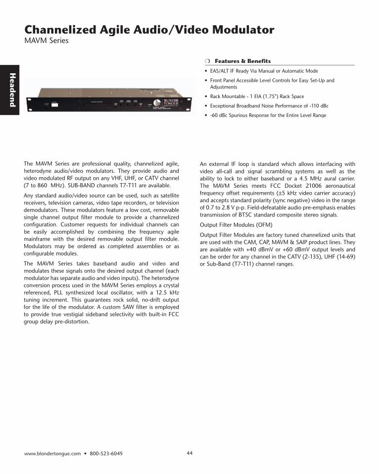
The MAVM Series are professional quality, channelized agile, heterodyne audio/video modulators. They provide audio and video modulated RF output on any VHF, UHF, or CATV channel (7 to 860 MHz). SUB-BAND channels T7-T11 are available.
Any standard audio/video source can be used, such as satellite receivers, television cameras, video tape recorders, or television demodulators. These modulators feature a low cost, removable single channel output filter module to provide a channelized configuration. Customer requests for individual channels can be easily accomplished by combining the frequency agile mainframe with the desired removable output filter module. Modulators may be ordered as completed assemblies or as configurable modules.
The MAVM Series takes baseband audio and video and modulates these signals onto the desired output channel (each modulator has separate audio and video inputs). The heterodyne conversion process used in the MAVM Series employs a crystal referenced, PLL synthesized local oscillator, with a 12.5 kHz tuning increment. This guarantees rock solid, no-drift output for the life of the modulator. A custom SAW filter is employed to provide true vestigial sideband selectivity with built-in FCC group delay pre-distortion.
• EAS/ALT IF Ready Via Manual or Automatic Mode
• Front Panel Accessible Level Controls for Easy Set-Up and Adjustments
• Rack Mountable - 1 EIA (1.75") Rack Space
• Exceptional Broadband Noise Performance of -110 dBc
• -60 dBc Spurious Response for the Entire Level Range
An external IF loop is standard which allows interfacing with video all-call and signal scrambling systems as well as the ability to lock to either baseband or a 4.5 MHz aural carrier. The MAVM Series meets FCC Docket 21006 aeronautical frequency offset requirements (±5 kHz video carrier accuracy) and accepts standard polarity (sync negative) video in the range of 0.7 to 2.8 V p-p. Field-defeatable audio pre-emphasis enables transmission of BTSC standard composite stereo signals.
Output Filter Modules (OFM)
Output Filter Modules are factory tuned channelized units that are used with the CAM, CAP, MAVM & SAIP product lines. They are available with +40 dBmV or +60 dBmV output levels and can be order for any channel in the CATV (2-135), UHF (14-69) or Sub-Band (T7-T11) channel ranges.
Hea
den
d
www.blondertongue.com • 800-523-604945
Channelized Agile Audio/Video Modulator MAVM Series
OVEROVER
AURAL VIDEOAUDIO
MOD POWER
CHANNEL
OUTPUTLEVEL
MOD
CARRIER LEVELLEVELOVERMOD POWER
CHANNEL
OUTPUTLEVEL
AURALCARRIER
VIDEOLEVEL
AUDIOLEVEL
OVERMOD
OVERMOD POWER
CHANNEL
OUTPUTLEVEL
VIDEOLEVEL
AUDIOLEVEL
AURALCARRIER
OVERMOD
MAVM-863 SERIESAUDIO VIDEO MODULATOR
MAVM-863
MAVM-863
MAVM-863-P
S
OFM-860
OFM-860
OVERMOD POWER
OVERMOD
AURALCARRIER
VIDEOLEVEL
AUDIOLEVEL
OUTPUTLEVEL
CHANNEL
CHANNEL SELECT OR
MAVM-861 SERIESAUDIO VIDEO MODULATOR
MAVM-861-MF
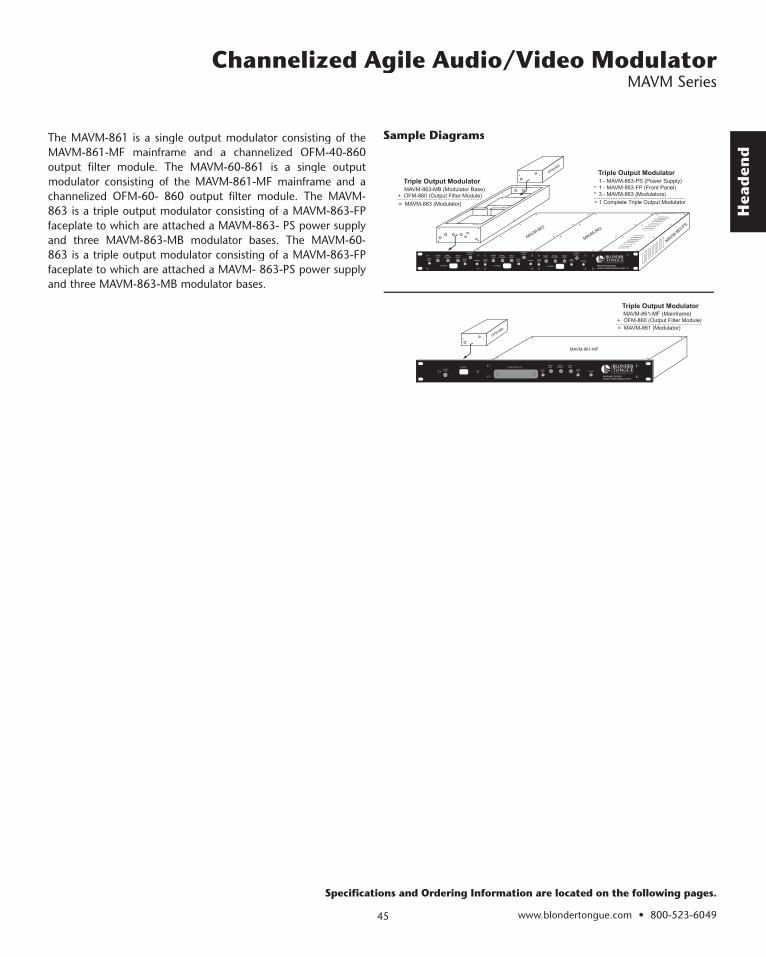
MAVM-863-MB (Modulator Base)+ OFM-860 (Output Filter Module)
= MAVM-863 (Modulator)
1 - MAVM-863-PS (Power Supply)1 - MAVM-863-FP (Front Panel)3 - MAVM-863 (Modulators)
1 Complete Triple Output Modulator
Triple Output ModulatorTriple Output Modulator
++
=
MAVM-861-MF (Mainframe)+ OFM-860 (Output Filter Module)= MAVM-861 (Modulator)
Triple Output Modulator
The MAVM-861 is a single output modulator consisting of the MAVM-861-MF mainframe and a channelized OFM-40-860 output filter module. The MAVM-60-861 is a single output modulator consisting of the MAVM-861-MF mainframe and a channelized OFM-60- 860 output filter module. The MAVM-863 is a triple output modulator consisting of a MAVM-863-FP faceplate to which are attached a MAVM-863- PS power supply and three MAVM-863-MB modulator bases. The MAVM-60-863 is a triple output modulator consisting of a MAVM-863-FP faceplate to which are attached a MAVM- 863-PS power supply and three MAVM-863-MB modulator bases.
Specifications and Ordering Information are located on the following pages.
Sample Diagrams
Head
end
www.blondertongue.com • 800-523-6049 46
Channelized Agile Audio/Video Modulator MAVM Series
SpecificationsRF
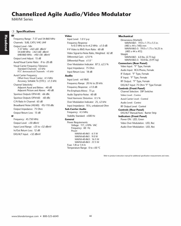
Frequency Range: 7-37 and 54-860 MHzChannels: SUB, CATV, VHF, UHFOutput Level - Min 7-37 MHz: +42/+60 dBmV 54-648 MHz: +42/+60 dBmV 648-860 MHz: +40/+58 dBmVOutput Level Adjust: 15 dBAural/Visual Carrier Ratio: -9 to -20 dBVisual Carrier Frequency Tolerance Standard Channels: ±5 kHz FCC Aeronautical Channels: ±5 kHzAural Carrier Frequency Offset from Visual Carrier: 4.5 MHz Accuracy, Settable To (STD.): ±1.5 kHzChannel Selectivity: Adjacent Aural and Below: -40 dB Adjacent Picture and Above: -40 dBSpurious Outputs OFM-40: -66 dBcSpurious Outputs OFM-60: -60 dBcC/N Ratio In Channel: 65 dBBroadband Noise (40/60): -95/-110 dBcOutput Impedance: 75 OhmOutput Return Loss: 15 dB
IFFrequency: 45.750 MHzOutput Lev el: +30 dBmVInput Lev el Range: +25 to +32 dBmVIn/Out Return Loss: 12 dBEAS/ALT Input: +32 dBmV
VideoInput Level: 1.0 V p-pFrequency Response fv-0.5 MHz to fv+4.2 MHz: ±1.0 dBP-P Video to RMS Hum Ratio: 60 dBVideo Signal-to-Noise Ratio, Weighted: 62 dBDifferential Gain: ±2.0 %Differential Phase: ±1.0 °Over Modulation Indicator: 87.5, ±2.5 %Input Impedance: 75 OhmInput Return Loss: 18 dB
AudioInput Level: mV RMSFrequency Range: 20 Hz to 20 kHzFrequency Response: ±1.0 dBPre-Emphasis-Mono: 75 µsAudio Signal-to-Noise: 60 dBTotal Harmonic Distortion: 0.5 %Over Modulation Indicator: 25, ±2 kHzInput Impedance: 10 k, unbalanced Ohm
Sub-Carrier AudioFrequency: 4.5 MHzStability Standard: ±500 Hz
GeneralPower Requirements Voltage: 117, ±10% VAC Frequency: 60 Hz Power MAVM-40-861: 6.5 W MAVM-60-861: 9.0 W MAVM-40-863: 16.5 W MAVM-60-863: 22.5 WFuse: 1/8 or 1/4 ATemperature Range: 0 to +50 °C
MechanicalDimensions (WxHxD) MAVM-861: 19.0 x 1.75 x 5.5 in. (483 x 44 x 140) mm MAVM-863-3: 19.0 x 1.75 x 16.25 in. (483 x 44 x 413)Weight MAVM-861: 6.0 lbs. (2.73 kg) MAVM-863-3: 10.8 lbs. (4.91 kg)
Connectors (Rear Panel)Video Input: "F" Type, FemaleAudio Input: RCA Phono, FemaleIF Output: "F" Type, FemaleIF Input: "F" Type, FemaleRF Output: "F" Type, FemaleEAS/ALT Input: 75 Ohm "F" Type Female
Controls (Front Panel)Channel Selection: DIP SwitchesVideo Level: ControlAural Carrier Level: ControlAudio Level: ControlRF Output Level: Control
Controls (Rear Panel)EAS/ALT Manual/Auto: Barrier Strip
Indicators (Front Panel)Power ON: LED, GreenVideo Over Modulation: LED, RedAudio Over Modulation: LED, Red
Refer to product instruction manual for additional specification measurements and notes.

Hea
den
d
www.blondertongue.com • 800-523-604947
Channelized Agile Audio/Video Modulator MAVM Series
Ordering Information
Model Stock No. DescriptionMAVM-60-861 7977B 300 Channelized Agile Audio/Video Modulator +60 dBmV, 54-300 MHz MAVM-60-861 7977B 756 Channelized Agile Audio/Video Modulator +60 dBmV, 300-756 MHz MAVM-60-861 7977B 860 Channelized Agile Audio/Video Modulator +60 dBmV, 756-860 MHz MAVM-60-861 S7977B 450 Channelized Agile Audio/Video Modulator +60 dBmV, 7-450 MHz (SUB & VHF) MAVM-60-861 U7977B 758 Channelized Agile Audio/Video Modulator +60 dBmV, 470-758 MHz (UHF) MAVM-60-861 U7977B 806 Channelized Agile Audio/Video Modulator +60 dBmV, 758-806 MHz (UHF) MAVM-60-863-1 7978B 300 Channelized Agile Audio/Video Modulator +60 dBmV, 54-300 MHz MAVM-60-863-1 7978B 756 Channelized Agile Audio/Video Modulator +60 dBmV, 300-756 MHz MAVM-60-863-1 7978B 860 Channelized Agile Audio/Video Modulator +60 dBmV, 756-860 MHz MAVM-60-863-1 S7978B 450 Channelized Agile Audio/Video Modulator +60 dBmV, 7-450 MHz (SUB & VHF) MAVM-60-863-1 U7978B 806 Channelized Agile Audio/Video Modulator +60 dBmV, 758-806 MHz (UHF) MAVM-60-863-3 7979B 300 Channelized Agile Audio/Video Modulator +60 dBmV, 54-300 MHz, Three Channel Modulator MAVM-60-863-3 7979B 756 Channelized Agile Audio/Video Modulator +60 dBmV, 300-756 MHz, Three Channel Modulator MAVM-60-863-3 7979B 860 Channelized Agile Audio/Video Modulator +60 dBmV, 756-860 MHz, Three Channel Modulator MAVM-60-863-3 S7979B 450 Channelized Agile Audio/Video Modulator +60 dBmV, 7-450 MHz (SUB & VHF), Three Channel Modulator MAVM-60-863-3 U7979B 758 Channelized Agile Audio/Video Modulator +60 dBmV, 470-758 MHz (UHF), Three Channel Modulator MAVM-60-863-3 U7979B 806 Channelized Agile Audio/Video Modulator +60 dBmV, 758-806 MHz (UHF), Three Channel Modulator MAVM-861 7992B 400 Channelized Agile Audio/Video Modulator +40 dBmV, 54-400 MHz MAVM-861 7992B 756 Channelized Agile Audio/Video Modulator +40 dBmV, 400-756 MHz MAVM-861 7992B 860 Channelized Agile Audio/Video Modulator +40 dBmV, 756-860 MHz MAVM-861 S7992B 450 Channelized Agile Audio/Video Modulator +40 dBmV, 7-450 MHz (SUB & VHF) MAVM-861 U7992B 758 Channelized Agile Audio/Video Modulator +40 dBmV, 470-758 MHz (UHF) MAVM-861 U7992B 806 Channelized Agile Audio/Video Modulator +40 dBmV, 758-806 MHz (UHF) MAVM-861-MF 7982C Channelized Agile Audio/Video Modulator 54-860 MHz, Mainframe MAVM-863-1 7993B 300 Channelized Agile Audio/Video Modulator +40 dBmV, 54-300 MHz MAVM-863-1 7993B 756 Channelized Agile Audio/Video Modulator +40 dBmV, 300-756 MHz MAVM-863-1 7993B 860 Channelized Agile Audio/Video Modulator +40 dBmV, 756-860 MHz MAVM-863-1 S7993B 450 Channelized Agile Audio/Video Modulator +40 dBmV, 7-450 MHz (SUB & VHF) MAVM-863-1 U7993B 758 Channelized Agile Audio/Video Modulator +40 dBmV, 470-758 MHz (UHF) MAVM-863-1 U7993B 806 Channelized Agile Audio/Video Modulator +40 dBmV, 758-806 MHz (UHF) MAVM-863-3 7999B 300 Channelized Agile Audio/Video Modulator +40 dBmV, 54-300 MHz, Three Channel Modulator MAVM-863-3 7999B 756 Channelized Agile Audio/Video Modulator +40 dBmV, 300-756 MHz, Three Channel Modulator MAVM-863-3 7999B 860 Channelized Agile Audio/Video Modulator +40 dBmV, 756-860 MHz, Three Channel Modulator MAVM-863-3 S7999B 450 Channelized Agile Audio/Video Modulator +40 dBmV, 7-450 MHz ( SUB & VHF ), Three Channel Modulator MAVM-863-3 U7999B 758 Channelized Agile Audio/Video Modulator +40 dBmV, 470-758 MHz (UHF), Three Channel Modulator MAVM-863-3 U7999B 806 Channelized Agile Audio/Video Modulator +40 dBmV, 758-806 MHz (UHF), Three Channel Modulator MAVM-863-FP 7963B Channelized Agile Audio/Video Modulator 860 MHz, Front Panel MAVM-863-MB 7983B Channelized Agile Audio/Video Modulator, 860 MHz, Modulator Base MAVM-863-PS 7972A Channelized Agile Audio/Video Modulator, 860 MHz, Power Supply Output Filter Modules (OFM)Model Stock No. DescriptionOFM-40-860 U7984A 806 Output Filter Module +40 dBmV, 758-806 MHz (UHF) OFM-40-860 U7984A 758 Output Filter Module +40 dBmV, 470-758 MHz (UHF) OFM-40-860 S7984A 37 Output Filter Module +40 dBmV, 7-37 MHz (SUB) OFM-40-860 7984A 860 Output Filter Module +40 dBmV, 756-860 MHz OFM-40-860 7984A 300 Output Filter Module +40 dBmV, 54-300 MHz OFM-40-860 7984A 756 Output Filter Module +40 dBmV, 300-756 MHz OFM-60-860 U7985A 758 Output Filter Module +60 dBmV, 470-758 MHz (UHF) OFM-60-860 U7985A 806 Output Filter Module +60 dBmV, 758-806 MHz (UHF) OFM-60-860 S7985A 37 Output Filter Module +60 dBmV, 7-37 MHz (SUB) OFM-60-860 7985A 860 Output Filter Module +60 dBmV, 756-860 MHz OFM-60-860 7985A 756 Output Filter Module +60 dBmV, 300-756 MHz OFM-60-860 7985A 300 Output Filter Module +60 dBmV, 54-300 MHz
www.blondertongue.com • 800-523-6049 48
Head
end
Modular Headend System Overview
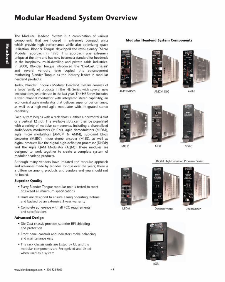
The Modular Headend System is a combination of various components that are housed in extremely compact units which provide high performance while also optimizing space utilization. Blonder Tongue developed the revolutionary ‘Micro Modular’ approach in 1995. This approach was extremely unique at the time and has now become a standard for headends in the hospitality, multi-dwelling and private cable industries. In 2000, Blonder Tongue introduced the ‘Die-Cast Chassis’ and several vendors have copied this advancement reinforcing Blonder Tongue as the industry leader in modular headend products.
Today, Blonder Tongue's Modular Headend System consists of a large family of products in the HE Series with several new introductions just released in the last year. The HE Series includes a fixed channel modulator with integrated stereo capability, an economical agile modulator that delivers superior performance, as well as a high-end agile modulator with integrated stereo capability.
Each system begins with a rack chassis, either a horizontal 4 slot or a vertical 12 slot. The available slots can then be populated with a variety of modular components, including a channelized audio/video modulators (MICM), agile demodulators (MIDM), agile micro modulators (AMCM & AMM), sub-band block converter (MSBC), micro stereo encoder (MISE), as well as digital products like the digital high-definition processor (DHDP) and the Agile QAM Modulator (AQM). These modules are designed to work together to create a complete system of modular headend products.
Although many vendors have imitated the modular approach and advances made by Blonder Tongue over the years, there is a difference among products and vendors and you should not be fooled.
Superior Quality
• Every Blonder Tongue modular unit is tested to meet or exceed all minimum specifications
• Units are designed to ensure a long operating lifetime and backed by an extensive 3 year warranty
• Complete adherence with all FCC requirements and specifications
Advanced Design
• Die-Cast chassis provides superior RFI shielding and protection
• Front panel controls and indicators make balancing and maintenance easy
• The rack chassis units are Listed by UL and the modular components are Recognized and Listed when used as a system
MIDMMIDM
AQM
Downconverter
AMCM-860S AMCM-860 AMM
MISE MSBCMICM
Modular Headend System Components
UpUpconverter
Digital High Definition Processor Series

www.blondertongue.com • 800-523-604949
Hea
den
d
Modular Headend System Rack Chassis and Power Supplies
Model Stock No. DescriptionMIRC-4D 7711 HE-4 Series Rack Chassis & Power Supply 19” Rack MountMIRC-12V 7715 HE-12 Series Vented Rack Chassis 19” Rack Mountable 2 RU Chassis for 12 Modular UnitsMIPS-12C 7722C HE-12 Series Power Supply 5.5 A on 5 VDC line, 4 A on 12 VDC lineMIRC-4CUBE-CH 7703 4 Slot Vertical Chassis Supports combinations of up to 4 MICM, AMCM or MIDM unitsMIRC-4CUBE-PS 7702 4 Slot Vertical Chassis Power Supply Unit AccessoriesModel Stock No. DescriptionMIBP-1 7787 Blank Panel Insert Single Modular Panel compatible with HE-12 / MIRC-12 ChassisMIBP-2 7788 Blank Panel Insert Dual Modular Panel compatible with HE-12 / MIRC-12 Chassis
MIPS-12CMIRC-4D
44 Slot Vertical Chassis Slot Vertical Chassis
MIRC-12VMIRC-12V
12 Slot Horizontal Chassis
General Power Requirements: 100 VAC to 240 VAC, ±10%Frequency: 50 to 60 HzTemperature Range: 0° to +50° COutput: +5 VDC @5.5 Amps, +12 VDC @4 Amps
MechanicalDimensions (WxHxD) : 4.16” x 3.5” x 7.50”Weight: 1.10 lbs (0.50 kg)Connectors/ImpedanceAC In put: IECDC Output: 37 pin D
IndicatorsPower 1 ON: LED, greenAccessories SuppliedAC Power Cable: 6 Ft, IEC, USA
Specifications
General General Power Requirements: 100 VAC to 240 VACFrequency: 50 to 60 HzTemperature Range: 0° to +50° Output Voltage & Current Capacity: +12 VDC @ 1.8 Amps + 5 VDC @ 1.8 Amps
Specifications
MIRC-4CUBE
Surveillance Application
The MIRC-4CUBE is extremely well suited for use in surveillance or security type applications. A video camera’s baseband video output can be modulated to any cable television channel and combined with existing TV signals to permit any outlet to monitor the camera feeds. This compact chassis can support up to 4 fixed channel or agile modulators and can be mounted in practically any location. The use of Blonder Tongue high performance modulators easily permits placing camera signals on adjacent channels.
Ordering Information
Head
end
www.blondertongue.com • 800-523-6049 50
Agile Modulator HE-12/HE-4 Series - AMCM-860 Series
Specifications
Features & Benefits
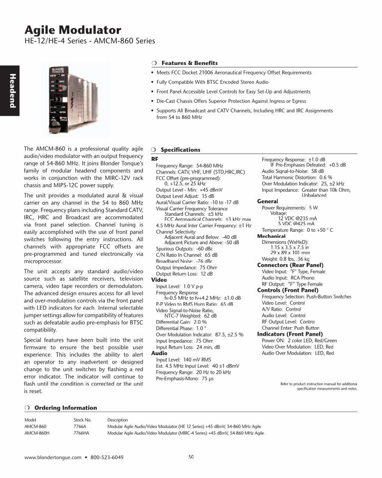
The AMCM-860 is a professional quality agile audio/video modulator with an output frequency range of 54-860 MHz. It joins Blonder Tongue’s family of modular headend components and works in conjunction with the MIRC-12V rack chassis and MIPS-12C power supply.
The unit provides a modulated aural & visual carrier on any channel in the 54 to 860 MHz range. Frequency plans including Standard CATV, IRC, HRC and Broadcast are accommodated via front panel selection. Channel tuning is easily accomplished with the use of front panel switches following the entry instructions. All channels with appropriate FCC offsets are pre-programmed and tuned electronically via microprocessor.
The unit accepts any standard audio/video source such as satellite receivers, television camera, video tape recorders or demodulators. The advanced design ensures access for all level and over-modulation controls via the front panel with LED indicators for each. Internal selectable jumper settings allow for compatibility of features such as defeatable audio pre-emphasis for BTSC compatibility.
Special features have been built into the unit firmware to ensure the best possible user experience. This includes the ability to alert an operator to any inadvertent or designed change to the unit switches by flashing a red error indicator. The indicator will continue to flash until the condition is corrected or the unit is reset.
RFFrequency Range: 54-860 MHzChannels: CATV, VHF, UHF (STD,HRC,IRC)FCC Offset (pre-programmed): 0, +12.5, or 25 kHzOutput Level - Min: +45 dBmVOutput Level Adjust: 15 dBAural/Visual Carrier Ratio: -10 to -17 dBVisual Carrier Frequency Tolerance Standard Channels: ±5 kHz FCC Aeronautical Channels: ±3 kHz max4.5 MHz Aural Inter Carrier Frequency: ±1 HzChannel Selectivity: Adjacent Aural and Below: -40 dB Adjacent Picture and Above: -50 dBSpurious Outputs: -60 dBcC/N Ratio In Channel: 65 dBBroadband Noise: -76 dBcOutput Impedance: 75 OhmOutput Return Loss: 12 dB
VideoInput Level: 1.0 V p-pFrequency Response fv-0.5 MHz to fv+4.2 MHz: ±1.0 dB P-P Video to RMS Hum Ratio: 65 dBVideo Signal-to-Noise Ratio, NTC-7 Weighted: 62 dBDifferential Gain: 2.0 %Differential Phase: 1.0 °Over Modulation Indicator: 87.5, ±2.5 %Input Impedance: 75 OhmInput Return Loss: 24 min, dB
AudioInput Level: 140 mV RMSExt. 4.5 MHz Input Level: 40 ±1 dBmVFrequency Range: 20 Hz to 20 kHzPre-Emphasis-Mono: 75 µs
Frequency Response: ±1.0 dB IF Pre-Emphases Defeated: +0.5 dBAudio Signal-to-Noise: 58 dBTotal Harmonic Distortion: 0.6 %Over Modulation Indicator: 25, ±2 kHzInput Impedance: Greater than 10k Ohm,
UnbalancedGeneral
Power Requirements: 5 W Voltage: 12 VDC @235 mA 5 VDC @425 mATemperature Range: 0 to +50 ° C
MechanicalDimensions (WxHxD): 1.15 x 3.5 x 7.5 in 29 x 89 x 101 mm Weight: 0.8 lbs, .36 kg
Connectors (Rear Panel)Video Input: "F" Type, FemaleAudio Input: RCA PhonoRF Output: “F” Type Female
Controls (Front Panel)Frequency Selection: Push-Button SwitchesVideo Level: ControlA/V Ratio: ControlAudio Level: ControlRF Output Level: ControlChannel Enter: Push Button
Indicators (Front Panel)Power ON: 2 color LED, Red/GreenVideo Over Modulation: LED, RedAudio Over Modulation: LED, Red
Ordering Information
Model Stock No. DescriptionAMCM-860 7766A Modular Agile Audio/Video Modulator (HE 12 Series) +45 dBmV, 54-860 MHz Agile AMCM-860H 7766HA Modular Agile Audio/Video Modulator (MIRC-4 Series) +45 dBmV, 54-860 MHz Agile
Refer to product instruction manual for additional specification measurements and notes.
• Meets FCC Docket 21006 Aeronautical Frequency Offset Requirements
• Fully Compatible With BTSC Encoded Stereo Audio
• Front Panel Accessible Level Controls for Easy Set-Up and Adjustments
• Die-Cast Chassis Offers Superior Protection Against Ingress or Egress
• Supports All Broadcast and CATV Channels, Including HRC and IRC Assignments from 54 to 860 MHz

Hea
den
d
www.blondertongue.com • 800-523-604951
Stereo Agile Modulator HE-12/HE-4 Series - AMCM-860S
Specifications
Ordering Information
RFFrequency Range: 54-860 MHzChannels: CATV, VHF, UHF (STD,HRC,IRC)FCC Offset (pre-programmed): 0, +12.5, or 25 kHzOutput Level - Min: +45 dBmVOutput Level Adjust: 15 dBAural/Visual Carrier Ratio: -10 to -17 dBVisual Carrier Frequency Tolerance Standard Channels: ±5 kHz FCC Aeronautical Channels: ±3 max kHz4.5 MHz Aural Inter Carrier Frequency: ±150 HzChannel Selectivity: Adjacent Aural and Below: -40 dB Adjacent Picture and Above: -50 dBSpurious Outputs: -60 dBcC/N Ratio In Channel: 65 dBBroadband Noise: -76 dBcOutput Impedance: 75 OhmOutput Return Loss: 12 dB
VideoInput Level: 1.0 V p-pFrequency Response fv-0.5 MHz to fv+4.2 MHz: ±1.0 dB P-P Video to RMS Hum Ratio: 65 dBVideo Signal-to-Noise Ratio, NTC-7 Weighted: 62 dBDifferential Gain: 2.0 %Differential Phase: 1.0 °Over Modulation Indicator: 87.5, ±2.5 %Input Impedance: 75 OhmInput Return Loss: 24 min, dB
Model Stock No. DescriptionAMCM-860S 7766S Modular Agile Stereo Audio/Video Modulator (HE 12 Series) +45 dBmV, 54-860 MHz Agile
The AMCM-860S provides modulated aural and visual carriers on any channel in the 54 to 860 MHz range. Standard CATV, IRC, HRC and Broadcast channel frequency plans are all accommodated. Pre-programmed FCC 21006 offsets provides frequency compliance on all mandated channels automatically.
Setting the desired output channel is easily accomplished with the LED channel display and using push button up/down switches. Once the desired channel is reached on the display the “enter” push button must be depressed to evoke the change. This feature prevents interference to other channels in the headend by going directly to the desired output channel rather than stepping through channels as indicated on the display. The enter button feature also guards against accidental up/down button touches that would otherwise cause inadvertent channel change. Should the “enter” button not be pushed within 30 seconds, the display will return to the original channel in memory.
The modulator utilizes SAW filtering with FCC group delay pre-distortion to provide true vestigial sideband selectivity and superior adjacent channel performance. The AMCM-860S takes baseband L/R audio and video from any standard source such as satellite receivers, video tape recorders, DVD players or television demodulators and modulates to the desired output channel.
AudioInput Lev el: 140 mV RMS minimumInput Impedance: 10kΩ, UnbalancedTotal Harmonic Distortion (%): 1.0Stereo Separation: 50 Hz - 100 Hz: 15 dB 100 Hz - 1 khz: 25 dB 12 kHz: 18 dB
GeneralPower Requirement: 5 W Voltage: 12 VDC @235 mA 5 VDC @425 mATemperature Range: 0 to +50 ° C
MechanicalDimensions (WxHxD): 1.15 x 3.5 x 7.5 in 29 x 89 x 191 mm Weight: 0.8 lbs, .36 kgConnectors (Rear Panel)Video Input: "F" Type, FemaleL/R Audio Input: RCA Phono (2)RF Output: “F” Type Female
Controls (Front Panel)Channel Selection: Push-Button Switches, UP/ONVideo Level: ControlA/V Ratio: ControlAudio Level: ControlRF Output Level: ControlChannel Enter: Push Button
Indicators (Front Panel)Channel Indicator: 2 Digit LED, RedPower ON: LED, GreenVideo Over Modulation: LED, RedAudio Over Modulation: LED, RedStereo Indicator: LED, Red
• Integrated Stereo Encoder
• Meets FCC Docket 21006 Aeronautical Frequency Offset Requirements
• Front Panel Accessible Level Controls for Easy Set-Up and Adjustments
• Die-Cast Chassis Offers Superior Protection Against Ingress or Egress
• Supports All Broadcast and CATV Channels, Including HRC and IRC Assignments from 54 to 860 MHz
Features & Benefits

www.blondertongue.com • 800-523-6049 52
Head
end
Specifications
• Economical Frequency Agility
• Die Cast Chassis Offers Superior RFI Protection
• CATV Channel Range 2 to 125 via Two Models
• FCC Docket 21006 Compliance for Aeronautical Frequency Offsets
• BTSC Compatible
The AMM Series are economical CATV agile audio/video modulators. They join Blonder Tongue's family of modular headend components and work in conjunction with the MIRC-12V rack chassis and MIPS-12C power supply. Two bandized models are available to cover channel frequencies between 54-806 MHz. The AMML-550 provides channel coverage from 2-78 (54-550 MHz) and the AMMH-806 from channels 55-125 (408-806 MHz).
The AMM-806 combines the frequency ranges of the AMML and AMMH into a single unit for CATV channels 2-125. Channel selection is done by easy to use front panel DIP switches. FCC frequency offsets per Docket 21006 are automatic via the units internal pre-programmed micro processor. The AMM Series accept standard audio/video sources such as satellite receivers, television camera, video tape recorders or demodulators.The advanced design ensures access for all level and over-modulation controls via the front panel. The audio pre-emphasis can be disabled internally for use with a BTSC Stereo Encoder.
RFCATV Frequency Range: AMML-550: 54-550 MHz (Ch’s 2-78, 95-99) AMMH-806: 408-806 (Ch’s 55-94, 100-125) AMM-806: 54-806 (Ch's 2-125)Output LevelL 35-45 dBmV, Continuously VariableAural/Visual Carrier Ratio: -12 to -18 dBVisual Carrier Frequency Tolerance Standard Channels: ±10 kHz FCC Aeronautical Channels (AMML Only): ±5 kHz4.5 MHz Aural Inter Carrier Frequency: ±150 Hz (max)Spurious Outputs: -60 dBcC/N Ratio In Channel: 60 dBBroadband Noise: -75 dBcOutput Impedance: 75 OhmOutput Return Loss: 10 dB
VideoInput Level: 1.0 V p-pFrequency Response fv-0.5 MHz to fv+4.2 MHz: ±1.0 dBInput Impedance: 75 OhmInput Return Loss: 18 min, dBDifferential Phase: 2.0°Differential Gain: 1.0%Group Delay Response: Meets FCC CATV Predistortion Requirements
for Color Operation
AudioInput Level: 0.4 to 4.0 V p-pFrequency Range: 30 Hz to 15 kHz, ± 0.5 dB (Exceeds 100 kHz with Pre-emphasis
Defeated)Input Impedance: 10k Ohm, UnbalancedDistortion: 30 Hz to 15 KHz 0.6%
GeneralPower Requirements 12 VDC @ 155mA 5 VDC @ 265ATemperature: 0° to 50° C
MechanicalDimensions (WxHxD): 1.15 x 3.5 x 7.5 in 29 x 89 x 191 mmWeight: 0.8 lbs, .36 kg
Connectors (Rear Panel)Video Input: “F” Type, FemaleAudio Input: RCA PhonoRF Output: “F” Type FemalePower: Header, 3 Pin
Controls (Front Panel)Channel Selection: Dip SwitchesVideo Level: ControlA/V Ratio: ControlAudio Level: ControlRF Output Level: Control
Indicator (Front Panel)Power ON: LED
Ordering Information
Agile Modulator HE-12/HE-4 Series - AMM Series
Stock No. Model DescriptionAMML-550 7761 Modular Agile Audio/Video Modulator, +45 dBmV, 54-550 MHz Agile AMMH-806 7762 Modular Agile Audio/Video Modulator, +45 dBmV, 408-806 MHz Agile AMM-806 7763 Modular Agile Audio/Video Modulator, +45 dBmV, 54-806 MHz Agile
Features & Benefits

www.blondertongue.com • 800-523-604953
Hea
den
d
Specifications
Ordering Information
Features & Benefits
The MICM-45 is a professional quality, channelized, heterodyne audio/video modulator which provides modulated RF carrier output on any single VHF channel, including: broadcast TV (2-13), CATV (14-135). It is ideal for placing audio and video onto any unused VHF channel. Any standard audio/video source can be used, such as satellite receivers, television cameras, video tape recorders, or television demodulators. The MICM-45 utilizes SAW filtering with FCC group delay pre-distortion to provide true vestigial sideband selectivity which makes it perfect for use in adjacent channel systems.
The MICM-45C takes baseband audio and video and modulates these signals onto the desired output channel. The MICM-45S takes baseband L/R audio and video and modulates these signals into the desired output channel. The heterodyne conversion process used in the unit employs a crystal referenced, PLL synthesized local oscillator. This guarantees rock solid, no-drift output for the life of the modulator. The MICM-45 meets FCC Docket 21006 aeronautical frequency offset requirements (±5 kHz video carrier accuracy). The modulator accepts standard polarity (sync negative) video in the range of 0.7 to 2.5 V p-p. It has field defeatable audio pre-emphasis to provide stereo compatibility with any external BTSC stereo generator providing a composite stereo baseband output.
The MICM-45S is a stereo A/V modulator providing a stereo audio and video modulated RF carrier on any single VHF channel. All other features and specifications are identical to the MICM-45C except as noted.
RF Frequency Range: 54-860 MHz (Broadcast 2-13, Cable 14-135)Output Lev el: +45 dBmVOutput Lev el Range: 10 dB continuously ad just-ableAural/Vi su al Carrier Ratio: -11 to -19 dB continuously adjustableVisual Carrier Frequency Tol er ance: ±10 kHz (standard channels) ± 5 kHz (aeronautical channels)Aural Carrier: 4.5 MHz above vi su alFrequency Set ting: ±1.5 kHzSpurious Out puts: -60 dBc, minC/N Ratio In Channel: 60 dBBroadband Noise: -90 dBOutput Re turn Loss: 12 dBIF (Internal) Frequency: 45.750 MHz
Video Input Lev el: 1.0 V p-p for 87.5 % Mod u la tionFrequency Response fv -0.5 MHz to fv +4.2 MHz: ±1.0 dBVideo C/N: 60 dB (4 MHz BW)P-P Vid eo to RMS Hum Ra tio: 60 dBDifferential Gain: ±4.0 % @ 87.5% ModulationDifferential Phase: ± 2° @ 87.5% Modulation Input Re turn Loss: 18 dB
AudioInput Lev el: 140 mV RMS for 25 kHz Peak DeviationInput Impedance: 10k Ohm, UnbalancedFrequency Range: 20 Hz to 20 kHz (MICM-45C)Frequency Response: ±1.0 dB, (50 Hz to 12 kHz) Reference to Std.
75 µs Pre-em pha sis (MICM-45C)± 0.3 dB (50 Hz to 50 kHz) (MICM-45S)in Stereo Configuration w/o pre-emphasis
Total Harmonic Distortion (%): 1.0 at 25 kHz DeviationStereo Separation (MICM-45S): 50 Hz - 100 Hz: 15 dB 100 Hz - 1 kHz: 25 dB 12 kHz: 18 dBAural Intercarrier: ±5 kHz (0° to +50° C), std.
General Power Re quire ments
External: 12 VDC @ 160 mA +5 VDC @ 130 mA (MICM-C)+5 VDC @180 mA (MICM-S)
Temperature Range: 0° to +50° C Mechanical
Dimensions (WxHxD): 1.20 x 3.5 x 7.50 in, 29 x 89 x 191 mmWeight: 0.65 lbs (0.30 kg)
Connectors/ImpedanceAudio In put: RCA Phono, fe male (MICM-45C)L/R Audio Inputs: RCA Phono, femaleVideo In put: 75 Ohm “F” type, fe maleRF Out put: 75 Ohm “F” type, female
ControlsVideo Level: PotAudio Level: PotAural Carrier Level: PotRF Out put Lev el: Pot
IndicatorsPower ON: LED, greenVideo Over Modulation: LED, red (MICM-45S)Audio Over Modulation: LED, red (MICM-45S)Stereo Indicator: LED, red (MICM-45S)
Model Stock No. DescriptionMICM-45C 7797C 600 HE-12 & HE-4 Series Channelized Audio/Video Modulator, +45 dBmV, 54-600 MHz MICM-45C 7797C 860 HE-12 & HE-4 Series Channelized Audio/Video Modulator +45 dBmV, 600-860 MHz MICM-45S 7797S 600 HE-12 & HE-4 Series Channelized Stereo Audio/Video Modulator +45 dBmV, 54-600 MHz MICM-45S 7797S 860 HE-12 & HE-4 Series Channelized Stereo Audio/Video Modulator +45 dBmV, 600-860 MHz
Refer to product instruction manual for additional specification measurements and notes.
• 5-860 MHz Channelized Audio/Video Modulator
• SAW Filtered to True Adjacent Channel Response
• Die-Cast Chassis Offers Superior Protection Against Ingress or Egress
• Front Panel Accessible Level Controls for Easy Set-Up and Adjustment
• Integrated Stereo Encoder Available
Audio/Video Modulator HE-12/HE-4 Series - MICM Series

www.blondertongue.com • 800-523-6049 54
Head
end
Specifications
Features & Benefits
The MIDM is a professional quality agile audio/video demodulator and is intended for both CATV and VHF & UHF applications. The unit is in a "single width" Die-Cast housing that allow deployment of up to 12 demodulator units in a MIRC-12 chassis.
The MIDM demodulates standard CATV, IRC and HRC channels and is capable for "Cherry Picking" of CATV channels in preparation for remodulation. The input frequency range is agile, allowing selection of any CATV channel from 54 to 806 MHz. Baseband audio and video are provided as outputs. It is ideal for off-air signal processing (audio/video processing and remodulation) applications. Baseband audio and video are provided as outputs. The MIDM features rock solid, phase lock loop (PLL) synthesized frequency control. Agile frequency selection is accomplished via front panel channel up/down buttons with a LED channel readout for easy on-the-fly channel changes. A channel lockout mode is also provided to prevent accidental channel changes. Non-volatile memory maintains the programmed channel selection in case of power loss. The MIDM is compatible with any modulators requiring a baseband input, and can be used in any combination with the MIPS-12C power supply in a MIRC-12 chassis.
RFFrequency: Range: 54-806 MHz, VHF, UHF, CATV (Std., IRC, HRC)Input Lev el Range: -5 to +30 dBm VHF/UHF, +2 to +12 dBmV (CATV)Noise Figure: 8 dBImage Rejection: VHF 60 dBInput Impedance: 75 Ohm
Video Output Lev el: 1.0 V p-p Output Impedance: 75 Ohm
Audio Output Lev el: 1 Vp-p Output Impedance: 600 Ohm, Unbalanced
General Power Re quire ments - External: 12 VDC @ 140 mA 5 VDC @ 150 mATemperature Range: 0° to +50° C
Mechanical Dimensions (WxHxD): 1.0 x 3.5 x 7.50 in 29 x 89 x 191 mmWeight: 1.2 lbs (0.56 kg)
Connectors/ImpedanceAudio Out put: RCA Phono, Fe maleVideo Output: 75 Ohm “F” Type, Fe maleRF In put: 75 Ohm “F” Type, FemalePower: Locking Header, 3 Pin
ControlsChannel Selection: Push ButtonsANT/CATV: Push ButtonPower On/OFF: Push ButtonChannel Lock: Push ButtonAudio Level: PotVideo Level: Pot
Indicators Channel: 2 Digit, 7 Segment LED
Ordering Information
Model Stock No. DescriptionMIDM-806C 7740C HE-12 Series Agile Audio/Video Demodulator 54-806 MHz UHF/VHF/CATV Input (STD,HRC,IRC)
• Die-Cast Chassis Offers Superior Protection Against Ingress or Egress
• Demodulates Any Channel 54-806 MHz
• LED Display Makes Agile Channel Selection Easy
• Compatible with MICM-45 Modulator for Compact Off-Channel Processor Solution
Agile Demodulator HE-12/HE-4 Series - MIDM
www.blondertongue.com • 800-523-604955
Hea
den
d
Modular Sub Band Converter HE-12/HE-4 Series - MSBC
Specifications
Ordering Information
• Up-converts Entire Sub-band to Channels 7-13
• 3 dB Conversion Gain
• Die Cast Chassis Provides Unsurpassed RFI Shielding
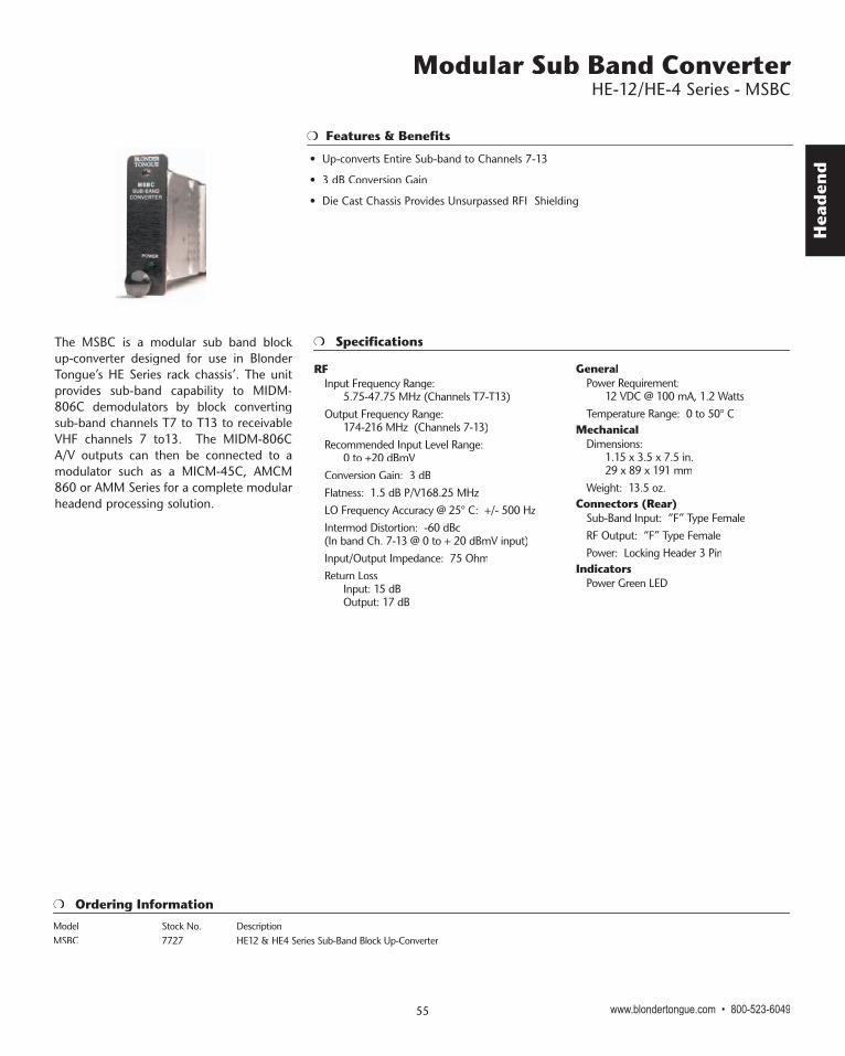
The MSBC is a modular sub band block up-converter designed for use in Blonder Tongue’s HE Series rack chassis’. The unit provides sub-band capability to MIDM-806C demodulators by block converting sub-band channels T7 to T13 to receivable VHF channels 7 to13. The MIDM-806C A/V outputs can then be connected to a modulator such as a MICM-45C, AMCM 860 or AMM Series for a complete modular headend processing solution.
RFInput Frequency Range: 5.75-47.75 MHz (Channels T7-T13) Output Frequency Range: 174-216 MHz (Channels 7-13)Recommended Input Level Range: 0 to +20 dBmVConversion Gain: 3 dBFlatness: 1.5 dB P/V168.25 MHz LO Frequency Accuracy @ 25° C: +/- 500 HzIntermod Distortion: -60 dBc (In band Ch. 7-13 @ 0 to + 20 dBmV input)Input/Output Impedance: 75 OhmReturn Loss Input: 15 dB Output: 17 dB
Model Stock No. DescriptionMSBC 7727 HE12 & HE4 Series Sub-Band Block Up-Converter
Features & Benefits
GeneralPower Requirement: 12 VDC @ 100 mA, 1.2 WattsTemperature Range: 0 to 50° C
Mechanical Dimensions: 1.15 x 3.5 x 7.5 in. 29 x 89 x 191 mmWeight: 13.5 oz.
Connectors (Rear)Sub-Band Input: “F” Type FemaleRF Output: “F” Type FemalePower: Locking Header 3 Pin
IndicatorsPower Green LED
Head
end
Specifications
Ordering Information
Features & Benefits
The MISE Stereo Encoder provides an economical solution for service providers wanting to deliver programs in stereo. The MISE is intended for use with Blonder Tongue’s MIRC-12 rack chassis’ with it’s associated power supply. The modular design provides an efficient compact means to accommodate 6 encoders coupled with 6 modulators or 12 encoders in 2RU’s of precious rack space. The MISE accepts baseband left and right audio inputs from sources such as a satellite receiver, demodulator, VCR or DVD and generates a composite BTSC stereo signal. The composite signal in turn is applied to a compatible modular audio/visual modulator such as a MICM-45B or AMCM-806. It is also compatible with any modulator that has a pre-emphasis defeat feature. The MISE features 24 dB stereo separation, a pilot lock indicator and a test tone generator to meet any demanding stereo insertion need.
Audio Input Input Impedance: 20K Ohms (unbalanced) 40K Ohms (balanced)Input Level: 250mVrms to 2.5Vrms
Video InputInput Impedance: 10K OhmsInput Level Range: 0.5 Vp-p to 2.0 Vp-p
Composite OutputOutput Impedance: 100 OhmsOutput Level: 1.1 Vp-p at 100% Modulation
Stereo PerformanceStereo Separation: 24 dB Typical, 20dB Min.Harmonic Distortion: 0.25%S/N Ratio: 65 dBFrequency Response: ±1dB from 50Hz to 12KHz
Test ToneFrequency: 10.396 KHz ± 50HzAmplitude: 0.5 Vp-p ± 10%
GeneralDC Power Input: +12 VDC @ 200 mAOperating Temp. Range: 0° to +50° C
MechanicalDimensions W x H X D: 1.15 x 3.5 x 7.5 in
29 x 89 x 191 mmWeight: .73lbs., .33 Kg
Model Stock No. DescriptionMISE 7725B HE-12 & HE-4 Series Micro Stereo Encoder
Stereo Encoder HE-12/HE-4 Series - MISE
www.blondertongue.com • 800-523-6049 56
• Modular Design Minimizes Rack Space
• 24 dB Stereo Separation with low Distortion
• Build-in Test Tone for Audio Level Calibration with Modulator
• Pilot Lock & Power LED Indicator
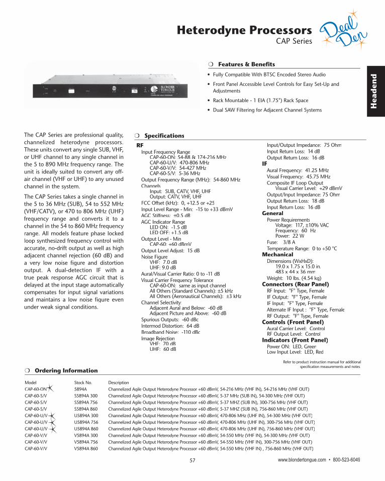
Hea
den
d
Heterodyne Processors CAP Series
www.blondertongue.com • 800-523-604957
Features & Benefits
The CAP Series are professional quality, channelized heterodyne processors. These units convert any single SUB, VHF, or UHF channel to any single channel in the 5 to 890 MHz frequency range. The unit is ideally suited to convert any off-air channel (VHF or UHF) to any unused channel in the system.
The CAP Series takes a single channel in the 5 to 36 MHz (SUB), 54 to 552 MHz (VHF/CATV), or 470 to 806 MHz (UHF) frequency range and converts it to a channel in the 54 to 860 MHz frequency range. All models feature phase locked loop synthesized frequency control with accurate, no-drift output as well as high adjacent channel rejection (60 dB) and a very low noise figure and distortion output. A dual-detection IF with a true peak response AGC circuit that is delayed at the input stage automatically compensates for input signal variations and maintains a low noise figure even under weak signal conditions.
Specifications
RFInput Frequency Range CAP-60-ON: 54-88 & 174-216 MHz CAP-60-U/V: 470-806 MHz CAP-60-V/V: 54-427 MHz CAP-60-S/V: 5-36 MHzOutput Frequency Range (MHz): 54-860 MHzChannels Input: SUB, CATV, VHF, UHF Output: CATV, VHF, UHFFCC Offset (kHz): 0, +12.5 or +25Input Level Range - Min: -15 to +33 dBmVAGC Stiffness: ±0.5 dBAGC Indicator Range LED ON: -1.5 dB LED OFF: +1.5 dBOutput Level - Min CAP-60: +60 dBmVOutput Level Adjust: 15 dBNoise Figure VHF: 7.0 dB UHF: 9.0 dBAural/Visual Carrier Ratio: 0 to -11 dBVisual Carrier Frequency Tolerance CAP-60-ON: same as input channel All Others (Standard Channels): ±5 kHz All Others (Aeronautical Channels): ±3 kHzChannel Selectivity: Adjacent Aural and Below: -60 dB Adjacent Picture and Above: -60 dBSpurious Outputs: -60 dBcIntermod Distortion: 64 dBBroadband Noise: -110 dBcImage Rejection VHF: 70 dB UHF: 60 dB
Input/Output Impedance: 75 OhmInput Return Loss: 14 dBOutput Return Loss: 16 dB
IFAural Frequency: 41.25 MHzVisual Frequency: 45.75 MHzComposite IF Loop Output Visual Carrier Level: +29 dBmVOutput/Input Impedance: 75 OhmOutput Return Loss: 18 dBInput Return Loss: 16 dB
GeneralPower Requirements Voltage: 117, ±10% VAC Frequency: 60 Hz Power: 22 WFuse: 3/8 ATemperature Range: 0 to +50 °C
MechanicalDimensions (WxHxD): 19.0 x 1.75 x 15.0 in. 483 x 44 x 36 mmWeight: 10 lbs. (4.54 kg)
Connectors (Rear Panel)RF Input: "F" Type, FemaleIF Output: "F" Type, FemaleIF Input: "F" Type, FemaleAlternate IF Input : "F" Type, FemaleRF Output: "F" Type, Female
Controls (Front Panel)Aural Carrier Level: ControlRF Output Level: Control
Indicators (Front Panel)Power ON: LED, GreenLow Input Level: LED, Red
Ordering Information
Model Stock No. DescriptionCAP-60-ON 5894A Channelized Agile Output Heterodyne Processor +60 dBmV, 54-216 MHz (VHF IN), 54-216 MHz (VHF OUT) CAP-60-S/V S5894A 300 Channelized Agile Output Heterodyne Processor +60 dBmV, 5-37 MHz (SUB IN), 54-300 MHz (VHF OUT) CAP-60-S/V S5894A 756 Channelized Agile Output Heterodyne Processor +60 dBmV, 5-37 MHZ (SUB IN), 300-756 MHz (VHF OUT) CAP-60-S/V S5894A 860 Channelized Agile Output Heterodyne Processor +60 dBmV, 5-37 MHZ (SUB IN), 756-860 MHz (VHF OUT) CAP-60-U/V U5894A 300 Channelized Agile Output Heterodyne Processor +60 dBmV, 470-806 MHz (UHF IN), 54-300 MHz (VHF OUT) CAP-60-U/V U5894A 756 Channelized Agile Output Heterodyne Processor +60 dBmV, 470-806 MHz (UHF IN), 300-756 MHz (VHF OUT) CAP-60-U/V U5894A 860 Channelized Agile Output Heterodyne Processor +60 dBmV, 470-806 MHz (UHF IN), 756-860 MHz (VHF OUT) CAP-60-V/V V5894A 300 Channelized Agile Output Heterodyne Processor +60 dBmV, 54-550 MHz (VHF IN), 54-300 MHz (VHF OUT) CAP-60-V/V V5894A 756 Channelized Agile Output Heterodyne Processor +60 dBmV, 54-550 MHz (VHF IN), 300-756 MHz (VHF OUT) CAP-60-V/V V5894A 860 Channelized Agile Output Heterodyne Processor +60 dBmV, 54-550 MHz (VHF IN) , 756-860 MHz (VHF OUT)
• Fully Compatible With BTSC Encoded Stereo Audio
• Front Panel Accessible Level Controls for Easy Set-Up and Adjustments
• Rack Mountable - 1 EIA (1.75") Rack Space
• Dual SAW Filtering for Adjacent Channel Systems
Refer to product instruction manual for additional specification measurements and notes.

Head
end
Features & Benefits
Heterodyne Processors AP Series
The AP Series are professional quality, agile heterodyne processors equipped with the Emergency Alert System (EAS) feature, which can also be used as an alternate IF input. These units convert any channel in the 50 to 806 MHz (7 to 43 MHz with Option 17) frequency range to any channel in the 50 to 550/750 MHz (7 to 550/750 MHz with Option 04) frequency range.
The AP Series is ideal for moving an off-air channel (VHF or UHF) or any single channel source to any unused channel (broadcast or CATV, including HRC and IRC assignments) in the system. Agile channel selection permits on-the-fly channel changes and reduces the need for large inventories of channelized products. Channel selection is accomplished with the use of simple to use front panel accessible dip switches. These processors have wide range of standard and optional features that make them very suitable for advanced CATV systems. Four models are available with different output level and frequency ranges and a variety of options.
www.blondertongue.com • 800-523-6049 58
• EAS/ALT IF Ready Via Manual or Automatic Mode
• Superior Broadband Noise Performance (-76 dB)
• Front Panel Accessible Level Controls for Easy Set-Up and Adjustments
• Rack Mountable - 1 EIA (1.75") Rack Space
All models feature rock solid, synthesized frequency control, with a tuning increment of 250 kHz. True vestigial sideband SAW filtering guarantees superior broadcast picture quality. Two SAW filters are used to ensure proper adjacent channel rejection. Delayed AGC circuitry automatically compensates for input signal variations. These processors have an external IF loop, which allows interfacing with video all-call and signal scrambling systems. The AP Series utilizes a standby carrier oscillator to provide a blank picture when the input level drops below usable level. This prevents a snowy picture from being delivered to the distribution network in the event of signal degradation or complete loss of picture. The EAS/ALT IF feature allows the customer to choose between manual and automatic selection of EAS/ALT IF input signal.
These processors provide extremely clean output signals with distortion products (-60 dB or better). An exceptionally low broadband noise floor (-76 dBc or better) makes the AP Series ideal for large, multiple channel headends without the need for additional filtering.
Specifications and Ordering Information are located on the following pages.

Hea
den
d
Specifications
Heterodyne Processors AP Series
RFInput Frequency Range Standard: 54-88 & 108-806 MHz Option 17 - Sub-band Input: 7-49 MHzInput Channels: SUB, VHF, UHF, CATV (STD,HRC)Output Frequency Range AP-40-550 & AP-60-550: 50-550 MHz AP-40-750 & AP-60-750: 50-750 MHzOption 04: AP-40-550 & AP-60-550: 7-550 MHzOutput Channels: SUB, CATV (STD,HRC,IRC)Tuning Increment: 250 kHzFCC Offset: 0, +12.5, or +25 kHzInput Level Range: -18 to +30 dBmVAGC Stiffness: 1.0 dBOutput Level - Min AP-40-550 & AP-40-750: +40 dBmV AP-60-550 & AP-60-750: +60 dBmVOutput Level Adjust: 10 dBNoise Figure VHF: 8 dB UHF: 10 dBAural/Visual Carrier Ratio: 0 to -10 dBVisual Carrier Frequency Tolerance Standard Channels: ±10 kHz FCC Aeronautical Channels: ±3 kHzChannel Selectivity: Adjacent Aural and Below: -65 dB Adjacent Picture and Above: -65 dBSpurious Outputs: -60 dBcIntermod Distortion: -64 dBBroadband Noise: -76 dBcImage Rejection: 65 dBBandpass Flatness fv to fv+4.5 MHz: ±1.0 dBInput/Output Impedance: 75 OhmInput Return Loss: 12 dBOutput Return Loss: 14 dB
IFAural Frequency: 41.25 MHzVisual Frequency: 45.75 MHzComposite IF Loop Output Aural Carrier Level: +13 dBmV Visual Carrier Level: +28 dBmVOutput/Input Impedance: 75 OhmOutput Return Loss: 12 dBInput Return Loss: 12 dBEAS/ALT IF Input Level: 28 dBmV @ 45.75 MHzEAS/ALT IF Switch Isolation: >60 dB
GeneralPower Requirements Voltage: 117, ±10% VAC Frequency: 60 HzPower - AP-40-450 & AP-40-550: 20 WPower - AP-60-450 & AP-60-550: 24WFuse: 3/8 ATemperature Range: 0 to +50 °C
MechanicalDimensions (WxHxD) 19.0 x 1.75 x 14.25 in. 483 x 44 x 362 mmWeight 9 lbs. (4.09 kg)
Connectors (Rear Panel)RF Input Standard - VHF/UHF: "F" Type, Female Option 17: Sub-band Input: "F" Type, FemaleIF Output: "F" Type, FemaleIF Input: "F" Type, FemaleRF Output: "F" Type, FemaleSerial Data Input & Output Option 20: SerialInput: RJ-12, FemaleEAS/ALT IF: “F” Type, Female
Controls (Front Panel)Frequency Selection Input: DIP Switches Output: DIP SwitchesFrequency Response Adjust: ControlsAural Carrier Level: ControlFrequency Fine Tune: ControlFCC Offset Selection Option 12: ABOC: DIP SwitchesRF Output Level: Control
Controls (Top Cover & Rear Panel)Standby Oscillator Threshold Adjust: ControlSub-band Input Channels Option 17: Slide SwitchEAS/ALT IF: 3 Position, Terminal Strip
Indicators (Front Panel)Power ON: LED, GreenEAS/ALT IF: LED, Green
Ordering Information
Model Stock No. DescriptionAP-40-550B 59802 Agile Heterodyne Processor with EAS +40 dBmV, 54-88/108-806 MHz Input, 50-550 MHz Output AP-40-750B 59803 Agile Heterodyne Processor with EAS +40 dBmV, 54-88/108-806 MHz Input, 50-750 MHz Output AP-60-550B 59817 Agile Heterodyne Processor with EAS +60 dBmV, 54-88/108-806 MHz Input, 50-550 MHz Output AP-60-750B 59818 Agile Heterodyne Processor with EAS +60 dBmV, 54-88/108-806 MHz Input, 50-750 MHz Output AccessoriesModel Stock No. DescriptionAP-OPT 04 59804 AP Series Option: Sub-Band Output AP-OPT 12 59122 AP Series Option: Automatic Broadcast Offset Correction AP-OPT 14 59144 AP Series Option: On Channel-lock AP-OPT 17 59177 AP Series Option: Sub-Band Input, 7-49 MHz
www.blondertongue.com • 800-523-604959
Refer to product instruction manual for additional specification measurements and notes.

Head
end
Specifications
Features & Benefits
Heterodyne Processors SAIP Series
The SAIP Series are professional quality, agile input and channelized agile output heterodyne processors. These units convert any channel in the 54 to 806 MHz frequency range to any channel in the 5 to 860 MHz frequency range. The SAIP Series is ideal for moving an off-air channel (VHF or UHF) or any single channel source to any unused channel (broadcast or CATV, including HRC and IRC assignments) in the system. For “on-channel” applications (CH2 IN, CH2 OUT), we recommend AP Series with Option 14 or the “CAP-ON” processors.
RFInput Frequency Range: 54-88 MHz 108-806 MHzOutput Frequency Range: 54-860 MHzChannels: VHF, CATV (STD,HRC,IRC), UHFTuning Increment Input Channels: 250 kHz Output Channels: 12.5 kHzFCC Offset: 0, +12.5, or +25 kHzOutput Level - Min: +60 dBmVOutput Level Adjust: 15 dBNoise Figure VHF: 8 dB UHF: 10 dBAural/Visual Carrier Ratio: 0 to -10 dBVisual Carrier Frequency Tolerance Standard Channels: ±5 kHz FCC Aeronautical Channels: ±3 kHzChannel Selectivity: Adjacent Aural and Below: -65 dB Adjacent Picture and Above: -65 dBSpurious Outputs: -60 dBcIntermod Distortion: -64 dBBroadband Noise: -95 dBcImage Rejection: 60 dBInput/Output Impedance: 75 OhmInput Return Loss: 12 dBOutput Return Loss: 14 dB
IFAural Frequency: 41.25 MHzVisual Frequency: 45.75 MHzComposite IF Loop Output Aural Carrier Level: +13 dBmV Visual Carrier Level: +28 dBmVOutput/Input Impedance: 75 Ohm
Output Return Loss: 12 dBInput Return Loss: 10 dB
GeneralPower Requirements Voltage: 117, ±10% VAC Frequency: 60 Hz Power - SAIP-60-860: 18 WFuse: 3/8 ATemperature Range: 0 to +50 °C
MechanicalDimensions (WxHxD): 19.0 x 1.75 x 9.5 in. 483 x 44 x 241 mmWeight: 6 lbs, 2.73 kg
Connectors (Rear Panel)RF Input: "F" Type, FemaleIF Output: "F" Type, FemaleIF Input: "F" Type, FemaleRF Output: "F" Type, Female
Controls (Front Panel)Frequency Selection Input: DIP Switches Output: DIP SwitchesAural Carrier Level: ControlRF Output Level: Control
Indicators (Front Panel)Power ON: LED, Green
www.blondertongue.com • 800-523-6049 60
Refer to product instruction manual for additional specification measurements and notes.
• EAS/ALT IF Ready Via Manual or Automatic Mode
• Front Panel Accessible Level Controls for Easy Set-Up and Adjustments
• Rack Mountable - 1 EIA (1.75") Rack Space
• Works in Conjunction with High Performance Channelized Output Filter Modules (OFM)
• Excellent Broadband Noise Performance of -95 dBc
Ordering Information
Model Stock No. DescriptionSAIP-60-860 5876B 300 Agile Input, Channelized Agile Output Processor +60 dBmV, 54-300 MHz SAIP-60-860 5876B 756 Agile Input, Channelized Agile Output Processor +60 dBmV, 300-756 MHz SAIP-60-860 5876B 860 Agile Input, Channelized Agile UHF Output Processor +60 dBmV, 756-860 MHz SAIP 60-860 MF 5885B Agile Input, Channelized Agile Output Processor 860 MHz, Mainframe

Hea
den
d
Agile Audio/Video Demodulator - Stereo Optional AD-1 Series
www.blondertongue.com • 800-523-604961
Specifications
Features & Benefits
The AD-1 is a professional quality, agile audio/video demodulator. The unit provides audio and video outputs from any analog input channel in the 54 to 88 and 108 to 806 MHz frequency range. The AD-1 is ideal for signal monitoring and signal conditioning (audio/video processing and remodulation) applications. Agile channel selection permits on-the-fly channel changes.
The AD-1 takes a single NTSC channel in the 54 to 88 and 108 to 806 MHz frequency range and demodulates the audio and video information. Baseband audio and video as well as 4.5 MHz audio subcarrier and multiplex audio are provided as outputs. The AD-1 features phase locked loop synthesized frequency control with a tuning increment of 250 kHz. Channel selection is accomplished with the use of simple to use front panel accessible dip switches. A Nyquist filter provides stable, accurate demodulation of the vestigial sideband signal. Additionally, this filter minimizes distortion and preserves the timing of the signal. Delayed AGC circuitry automatically compensates for input signal variations. The AD-1 also utilizes a quasi-synchronous video detector that has low differential gain and minimal phase distortion. A quadrature audio detector delivers a very low distortion audio output. The broadband multiplex audio, 4.5 MHz audio subcarrier, or the optional BTSC stereo (L/R) or SAP outputs make the AD-1 ideal for any stereo application.
RFInput Frequency Range Standard: 54-88 & 108-806 MHz Option 17: Sub-band Input: 7-49 MHzChannels: VHF, UHF (Input) CATV (STD,HRC,IRC)Tuning Increment: 250 kHzInput Level - Max: +20 dBmVNoise Figure VHF: 8-11 dB UHF: 10 dBImage Rejection - Min VHF: 65 dB UHF: 50 dBInput/Output Impedance: 75 Ohm
VideoFrequency Response fv+25 Hz to fv+4.0 MHz: Settable to ±1.0 dBOutput Level: 1.0 V p-pDifferential Gain: 3.0 %Differential Phase: 1.5 °Group Delay Response: ±50 nsOutput Impedance: 75 OhmOutput Return Loss: 25 dB
AudioMonoBaseband Frequency Response: 50 Hz to 15 KHz: ± 0.75 dBOutput Level: 500 mv RMS (Opt 29, 1.4 V RMS) Impedance: 600 Ohms, Unbalanced (STD) (Opt. 29, 600 Ohms, Balanced) Audio Signal-to-Noise: 57 dBTotal Harmonic Distortion: 0.6%Multiplexed Frequency Response: 50 Hz to 100 kHz: ±0.2 dB Output Level: 500 mV RMS Impedance: 600, unbalanced OhmStereo (Option 25)Baseband Frequency Response 50 Hz to 12 KHz (in-phase L/R inputs): +/- 0.75 dB Output Level Left or Right: 4.0 Vp-p Impedance: 600 Ohms, Balanced Separation 50 Hz – 10 KHz: 20 dBAudio Signal-to-Noise: 60 dB
Total Harmonic Distortion: <0.5%4.5 MHz Subcarrier Output Level: +28 dBmVImpedance: 75 Ohm
GeneralPower Requirements Voltage: 117, ±10% VAC Frequency: 60 Hz Power: 16 WFuse: 1/4 ATemperature Range: 0 to +50 °C
MechanicalDimensions (WxHxD): 19.0 x 1.75 x 14.5 in. 483 x 44 x 368 mmWeight: 5.5 lbs., 2.50 kg
Connectors (Rear Panel)RF Input Standard - VHF/UHF: "F" Type, Female Option 17: Sub-band Input: "F" Type, FemaleVideo Output: "F" Type, FemaleBaseband Audio Output: RCA Phono, Female (STD) Terminal Strip (Opt 25 + 29)Multiplexed (MPX) Audio Output: RCA Phono, Female (STD Only)4.5 MHz Subcarrier Audio Output: "F" Type, FemaleSerial Data Input & Output Option 20: Serial Input: RJ-12, Female
Controls (Front Panel)Frequency Selection: DIP SwitchesVideo Response: Controls
Controls (Top Cover & Rear Panel)Sub-band Input Channels Option 17: Slide SwitchL/R or SAP Audio Output Option 15: Contact Closure
Indicators (Front Panel)Power ON: LED, GreenStereo: LED, RED (Opt 25)
Ordering Information
Model Stock No. DescriptionAD-1B 5932 Agile Audio/Video Demodulator 54-88/108-806 MHz AD-1-OPT 17 59257 AD-1 Option: Sub-Band Input, 7-49 MHz AD-1-OPT 20 59250 AD-1 Option: Digital Control, Serial RS-232 AD-1-OPT 09 59259 AD-1 Option: Balanced Audio, 600 Ohm AD-1-OPT 25 59255 AD-1 Option: Stereo Audio Output, 600 Ohm Balanced
Refer to product instruction manual for additional specification measurements and notes.
• Stereo BTSC Outputs (Option 25)
• Rack Mountable - 1 EIA (1.75") Rack Space
• 250 kHz Tuning Increment - Supports Broadcast, CATV and UHF Assignments Including HRC & IRC
• AGC Circuitry Automatically Compensates for Input Level Variations
• 4.5 MHz Audio Subcarrier and Broadband Multiplex Audio Outputs
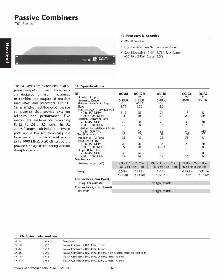
Head
end
www.blondertongue.com • 800-523-6049 62
Passive Combiners OC Series
Ordering Information
Features & Benefits
The OC Series are professional quality, passive output combiners. These units are designed for use in headends to combine the outputs of multiple modulators and processors. The OC Series employs radiation-proof passive components that provide excellent reliablity and performance. Five models are available for combining 8, 12, 16, 24 or 32 inputs. The OC Series features high isolation between ports and a low net combining loss from each of the broadband inputs (5 to 1000 MHz). A 20 dB test port is provided for signal monitoring without disrupting service.
Model Stock No. DescriptionOC-8d 5957 Passive Combiner 5-1000 MHz, 8 Ports OC-12D 5953 Passive Combiner 5-1000 MHz, 12 Ports OC-16 5950 Passive Combiner 5-1000 MHz, 16 Ports, High Isolation, Front/Rear Test Ports OC-24E 5794 Passive Combiner 5-1000 MHz, 24 Ports, Front Test Ports OC-32E 5795 Passive Combiner 5-1000 MHz, 32 Ports, Front Test Ports
• -20 dB Test Port
• High Isolation, Low Net Combining Loss
• Rack Mountable - 1 EIA (1.75") Rack Space, (OC-16 is 2 Rack Spaces 3.5")
Specifications
RF OC-8d OC-12D OC-16 OC-24 OC-32Number of Inputs: 8 12 16 24 32Frequency Range: 5-1000 5-1000 5-1000 50-1000 50-1000Flatness - Relative to Slope: 0.4 ±0.20 0.4Slope: 2.75 1.50 2.5Insertion Loss - Individual Port 40 to 450 MHz: 11.5 18 24 18 18 450 to 1000 MHz: 13 18 26 20 20Isolation - Adjacent Ports 40 to 450 MHz: 25 38 40 30 30 450 to 1000 MHz: 25 38 36 25 25Isolation - Non-Adjacent Ports 40 to 1000 MHz: 40 65 62 >40 >40Test Port Level: -20 -20 -20 -20 -20Impedance - All Ports: 75 75 75 75 75Input Return Loss 40 to 450 MHz: 20 20 18 20 20 450 to 1000 MHz: 19 20 16/14 18 18Output Return Loss 40 to 450 MHz: 20 16 18 18 18 450 to 1000 MHz: 19 16 15 16 16
MechanicalDimensions (WxHxD): 19.0 x 1.75 x 15.25 in.Dimensions (WxHxD): 19.0 x 1.75 x 15.25 in. 19.0 x 3.5 x 15.25 in. 19.0 x 1.75 x 8.0 in. 483 x 44 x 387 mm 483 x 89 x 387 mm 483 x 44 x 203 mmWeight: 6.5 lbs. 6.95 lbs. 9.0 lbs. 6.95 lbs. 6.95 lbs. 2.95 kgs. 3.18 kgs. 4.77 kgs. 3.16 kgs. 3.16 kgs.
Connectors (Rear Panel)RF Input & Outputs: "F" type, RF Input & Outputs: "F" type, female
Connectors (Front Panel)Test Port: "F" type, female

Hea
den
d
www.blondertongue.com • 800-523-604963
Active Combiners OCA Series
Specifications The OCA Series are professional quality, amplified output combiners. These units are designed for use in headends to combine and amplify the outputs of multiple modulators and processors. The OCA Series employs radiation-proof passive components that provide excellent signal reproduction and years of reliable service. Two models are available, including: OCA-8b, 8 inputs; and OCA-12, 12 inputs.
The OCA Series features a single push-pull hybrid amplifier which supplies sufficient gain for driving a distribution system directly. The overall gain of the unit is variable using a built-in manual gain control, accessible via the front panel. The OCA Series provides high isolation between ports and net combining gain from each of the broadband inputs (50 to 450 MHz). A 20 dB test port is provided for signal monitoring without disrupting service.
RFNumber of Inputs: 8Frequency Range: 50-450 MHzFlatness - Relative to Slope: ±0.25Output Level: +56 dBmVOverall Unit Gain: 22 dBGain Control Range: 14 dBCross Modulation: -57 dBSlope: ±0.75 dBTest Port Level: -20 dBImpedance - All Ports: 75 OhmInput Return Loss: 16 dBOutput Return Loss: 16 dB
GeneralPower Requirements Voltage: 117, ±10% VAC Frequency: 60 Hz Power: 10 WFuse: 3/8 ATemperature Range: 0 to +50 °C
MechanicalDimensions (WxHxD): 19.0 x 1.75 x 15.0 in. 483 x 44 x 381 mmWeight: 6.0 lbs, 2.73 kg
Connectors (Rear Panel)RF Input: "F" Type, FemaleRF Outputs: "F" Type, Female
Connectors (Front Panel)Test Port: "F" Type, Female
Controls (Front Panel)Gain Control: Control
Indicators (Front Panel)Power ON: LED, Green
Ordering InformationModel Stock No. DescriptionOCA-8b 5956 Active Combiner 50-450 MHz, 8 Ports OCA-12 5954 Active Combiner 50-540 MHz, 12 Ports
• Rack Mountable - 1 EIA (1.75") Rack Space
• -20 dB Test Port
• Single Push-Pull Hybrid Module Design for High Output with Low Distortion
Features & Benefits
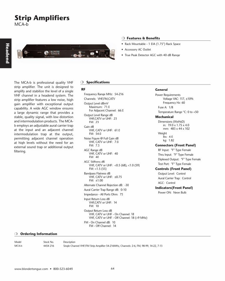
Head
end
Features & Benefits
The MCA-b is professional quality VHF strip amplifier. The unit is designed to amplify and stabilize the level of a single VHF channel in a headend system. The strip amplifier features a low noise, high gain amplifier with exceptional output capability. A wide AGC window ensures a large dynamic range that provides a stable, quality signal, with low distortion and intermodulation products. The MCA-b employs an adjustable aural carrier trap at the input and an adjacent channel intermodulation trap at the output, permitting adjacent channel operation at high levels without the need for an external sound trap or additional output filtering.
www.blondertongue.com • 800-523-6049 64
Strip Amplifi ers MCA-b
• Rack Mountable - 1 EIA (1.75") Rack Space
• Accessory AC Outlet
• True Peak Detector AGC with 40 dB Range
Specifications
RF Frequency Range MHz: 54-216Channels: VHF,FM,CATVOutput Level dBmV Maximum: 71.0 For Adjacent Channel: 66.0Output Level Range dB VHF,CATV or UHF: 23 FM: 23Gain dB VHF, CATV or UHF: 61.0 FM: 54.0Noise Figure @ Full Gain dB VHF, CATV or UHF: 7.0 FM: 7.5AGC Range dB VHF, CATV or UHF: 40 FM: 40AGC Stiffness dB VHF, CATV or UHF: <0.5 (68), <1.0 (59) FM: <1.5 (55)Bandpass Flatness dB VHF, CATV or UHF: ±0.75 FM: ±1.00 Alternate Channel Rejection dB: -30Aural Carrier Trap Range dB: 0-10Impedance - All Ports Ohm: 75Input Return Loss dB VHF,CATV or UHF: 14 FM: 10Output Return Loss dB VHF, CATV or UHF - On Channel: 18 VHF, CATV or UHF - Off Channel: 18 (>9 MHz)FM - On Channel dB: 10 FM - Off Channel: 14
GeneralPower Requirements Voltage VAC: 117, ±10% Frequency Hz: 60
Fuse A: 1/8Temperature Range °C: 0 to +50
MechanicalDimensions (WxHxD) in: 19.0 x 1.75 x 4.0 mm: 483 x 44 x 102Weight lbs: 4.0 kg: 1.82
Connectors (Front Panel)RF Input: "F" Type FemaleThru Input: "F" Type FemaleDiplexed Output: "F" Type FemaleTest Port: "F" Type Female
Controls (Front Panel)Output Level: ControlAural Carrier Trap: ControlAGC: Control
Indicators(Front Panel)Power ON: Neon Bulb
Ordering Information
Model Stock No. DescriptionMCA-b 4454 216 Single Channel VHF/FM Strip Amplifier 54-216MHz, Channels: 2-6, FM, 98-99, 14-22, 7-13
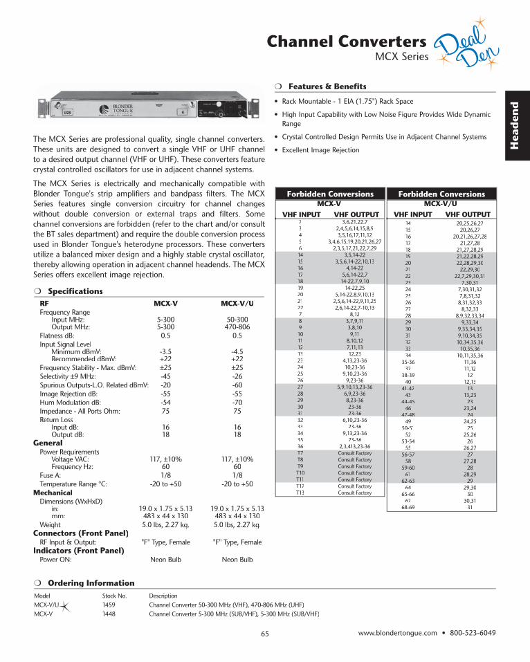
Hea
den
d
www.blondertongue.com • 800-523-604965
Features & Benefits
The MCX Series are professional quality, single channel converters. These units are designed to convert a single VHF or UHF channel to a desired output channel (VHF or UHF). These converters feature crystal controlled oscillators for use in adjacent channel systems.
The MCX Series is electrically and mechanically compatible with Blonder Tongue's strip amplifiers and bandpass filters. The MCX Series features single conversion circuitry for channel changes without double conversion or external traps and filters. Some channel conversions are forbidden (refer to the chart and/or consult the BT sales department) and require the double conversion process used in Blonder Tongue's heterodyne processors. These converters utilize a balanced mixer design and a highly stable crystal oscillator, thereby allowing operation in adjacent channel headends. The MCX Series offers excellent image rejection.
• Rack Mountable - 1 EIA (1.75") Rack Space
• High Input Capability with Low Noise Figure Provides Wide Dynamic Range
• Crystal Controlled Design Permits Use in Adjacent Channel Systems
• Excellent Image Rejection
Channel Converters MCX Series
Ordering InformationModel Stock No. DescriptionMCX-V/U 1459 Channel Converter 50-300 MHz (VHF), 470-806 MHz (UHF) MCX-V 1448 Channel Converter 5-300 MHz (SUB/VHF), 5-300 MHz (SUB/VHF)
SpecificationsRF MCX-V MCX-V/UFrequency Range Input MHz: 5-300 50-300 Output MHz: 5-300 470-806Flatness dB: 0.5 0.5Input Signal Level Minimum dBmV: -3.5 -4.5 Recommended dBmV: +22 +22Frequency Stability - Max. dBmV: ±25 ±25Selectivity ±9 MHz: -45 -26Spurious Outputs-L.O. Related dBmV: -20 -60Image Rejection dB: -55 -55Hum Modulation dB: -54 -70Impedance - All Ports Ohm: 75 75Return Loss Input dB: 16 16 Output dB: 18 18
GeneralPower Requirements Voltage VAC: 117, ±10% 117, ±10% Frequency Hz: 60 60Fuse A: 1/8 1/8Temperature Range °C: -20 to +50 -20 to +50
MechanicalDimensions (WxHxD) in: 19.0 x 1.75 x 5.13 19.0 x 1.75 x 5.13 mm: 483 x 44 x 130 483 x 44 x 130Weight 5.0 lbs, 2.27 kg. 5.0 lbs, 2.27 kg.
Connectors (Front Panel)RF Input & Output: "F" Type, Female "F" Type, Female
Indicators (Front Panel)Power ON: Neon Bulb Neon Bulb
23456141516171819202122789101112132324252627282930313233343536T7T8T9T10T11T12T13
3,6,21,22,72,4,5,6,14,15,8,93,5,16,17,11,12
3,4,6,15,19,20,21,26,272,3,5,17,21,22,7,29
3,5,14-223,5,6,14-22,10,13
4,14-225,6,14-22,714-22,7,9,1014-22,7,9,10
14-22,255,14-22,8,9,10,13
2,5,6,14-22,9,11,252,6,14-22,7-10,13
8,123,7,9,113,8,109,11
8,10,127,11,1312,23
4,13,23-3610,23-36
9,10,23-369,23-36
5,9,10,13,23-366,9,23-368,23-3623-3623-36
6,10,23-3623-36
9,13,23-3623-36
2,3,413,23-36Consult FactoryConsult FactoryConsult FactoryConsult FactoryConsult FactoryConsult FactoryConsult FactoryConsult Factory
Forbidden Conversions MCX-V VHF INPUT VHF OUTPUT
Forbidden Conversions
14151617181920212223232425262728293031323334
35-3637
38-3940
41-4243
44-4546
47-4847-4849
50-5152
53-5455
56-5758
59-6061
62-6364
65-6667
68-69
20,25,26,2720,26,27
20,21,26,27,2821,27,28
21,27,28,2921,27,28,2921,22,28,2922,28,29,30
22,29,3022,7,29,30,31
7,30,317,30,317,30,31,327,8,31,328,31,32,33
8,32,338,9,32,33,348,9,32,33,34
9,33,349,33,34,359,10,34,3510,34,35,36
10,35,3610,35,3610,11,35,36
11,3611,12
1212,1312,13
1313,23
2323,24
2424,25
2525,26
2626,2726,27
2727,28
2828,29
2929,30
3030,31
31
MCX-V/U VHF INPUT VHF OUTPUT
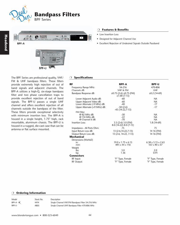
Head
end
www.blondertongue.com • 800-523-6049 66
Features & Benefits
The BPF Series are professional quality, VHF/FM & UHF bandpass filters. These filters provide extremely high rejection of out of band signals and adjacent channels. The BPF-A utilizes a high-Q, six-stage bandpass filter and two phase cancellation traps to provide excellent rejection of out of band signals. The BPF-U passes a single UHF channel and offers excellent rejection of all channels outside the bandpass of the filter. These filters provide exceptional selectivity with minimum insertion loss. The BPF-A is housed in a single height, 1.75" high, rack mountable, aluminum chassis. The BPF-U is housed in a rugged, die-cast case that can be antenna or flat surface mounted.
BPF-ABPF-A
BPF-U
Specifications
RF BPF-A BPF-UFrequency Range MHz: 54-216 470-806Channels dB: VHF & FM UHFBandpass Response dB: ±0.75 (2-6) ±0.75 (FM) ±0.2 (14-69) ±1.00 (7-13) Lower Adjacent Audio dB: -60 NA Upper Adjacent Video dB: -60 NA Lower Alternate (-9 MHz) dB: -40 -17 Upper Alternate (+9 MHz) dB: -50 (2-6) -17 -45 (14-22,7-13) FM Filter @ 82 MHz dB: -30 NA @ 114 MHz dB: -22 NA @ Channel 6 dB: -70 NAInsertion Loss: 3.5 (2-6) 3.0 (FM) 1.8 (14-69) 8.0 (14-22) 8.0 (7-13)Impedance - All Ports Ohm: 75 75Input Return Loss dB: 13 (2-6,14-22,7-13) 14 16 (FM)Output Return Loss dB: 13 (2-6, 14-22, 7-13) 14 16 (FM)
MechanicalDimensions (WxHxD) in: 19.0 x 1.75 x 6.13 6.38 x 3.13 x 2.63 mm: 483 x 44 x 156 162 x 80 x 67Weight lbs: 3.0 2.0 kg: 1.36 0.91
ConnectorsRF Input: "F" Type, Female "F" Type, FemaleRF Output: "F" Type, Female "F" Type, Female
Ordering Information
Model Stock No. DescriptionBPF-A 4414 Single Channel VHF/FM Bandpass Filter 54-216 MHz BPF-U 4805 Single Channel UHF Bandpass Filter 470-806 MHz
• Low Insertion Loss
• Designed for Adjacent Channel Use
• Excellent Rejection of Undesired Signals Outside Passband
Bandpass Filters BPF Series

Hea
den
d
www.blondertongue.com • 800-523-604967
Bandpass Filters BPF-Z and MXF Series
Specifications
Specifications
Features & Benefits
The BPF-z is a low cost, professional quality, VHF bandpass filter. This unit is designed to provide an additional level of bandpass selectivity when used in adjacent channel configurations. The BPF-z features high-Q filters and phase cancellation traps that provide excellent adjacent channel rejection. Trap adjustments can be made at the factory for improving the rejection characteristics of the filter. These adjustments are then locked in place to prevent inadvertent changes. The BPF-z is designed to work in conjunction with Blonder Tongue’s low cost Single Channel VHF Strip Amplifier (ZSCA).
RFFrequency Range: 54-88 & 120-216 MHzChannels: VHFBandpass Response 2-6: ±0.75 dB A-I: ±0.80 dB 7-13: ±1.20 dBSelectivity Lower Adjacent Audio: -55 dB Upper Adjacent Video: -50 dB Lower Alternate (-9 MHz): -35 dB Upper Alternate (+9 MHz): -45 dBInsertion Loss 2-6: 3.5 dB A-I: 5.0 dB 7-13: 7.0 dBImpedance - All Ports: 75 Ohm
MechanicalDimensions (WxHxD): 19.0 x 1.75 x 3.5 in. 483 x 44 x 89 mmWeight: 2.0 lbs., 0.91 kgConnectors (Rear Panel)RF Input: "F" Type, FemaleRF Output: "F" Type, Female
Controls (Front Panel)Lower Aural Trap Adjust: ControlsUpper Visual Trap Adjust: Controls
The MXF Series are professional quality, modular VHF/FM bandpass filters. This filter system consists of the MXF-B mounting base and up to 8 MXF bandpass filter modules. Filters are available for all of the standard broadcast TV channels (2-13) and two FM bands (88-108 MHz and 92-108 MHz). The MXF System may be used to separate channels from a single broadband antenna or combine two groups of four non-adjacent channels. Two filters are available for adding FM onto a system; FM-A for systems that include TV channel 5 and FM-B for systems that include TV channel 6. The MXF filter modules mount onto the MXF-B mounting base and can also be used as stand-alone filters.
RFFrequency Range:: 54-108 & 174-216 MHzChannels: VHF, FMSelectivity @ ±9 MHz: -10 dBInsertion Loss: MXF: 0.6 (2-6) dB, 1.1 (FM),
1.1 (7-13) dB MXF-B: 0.9 (2-6) dB, 1.5 (FM),
1.4 (7-13) dBImpedance - All Ports: 75 OhmInput & Output Return Loss: 17 (2-6), 8 (FM), 17 (7-13) dB
MechanicalDimensions (WxHxD) MXF: 2.00 x 2.00 x 2.00 in
51 x 51 x 51 mm MXF-B: 9.75 x 4.00 x 5.38 in
248 x 102 x 137 mmWeight: MXF: 0.25 lbs, 0.11 kg. MXF-B: 4.0 lbs, 1.82 kg.
ConnectorsRF Input & Output: MXF: "F" Type, Male MXF-B: “F” Type, Female
BPF-ZBPF-Z
Features & Benefits
MXFMXF MXF-BMXF-B
Ordering Information
Model Stock No. DescriptionBPF-Z 4419B Single Channel VHF Bandpass Filter 54-216 MHz MXF 3437 Modular Single Channel VHF/FM Bandpass Filter 54-216MHz, CHANNELS: 2-6, FMA, FMB, 7-13 MXF-B 3438 Modular Filter, Base Use with # 3437
• Rack Mountable - 1 EIA (1.75") Rack Space
• Single Channel VHF Bandpass Filter
• Sharp Skirt Selectivity
• Superior Adjacent Channel Rejection
• Modular Bandpass Filters
• VHF and FM Coverage
• Applications Include Filtered Channel Combiner and Separator
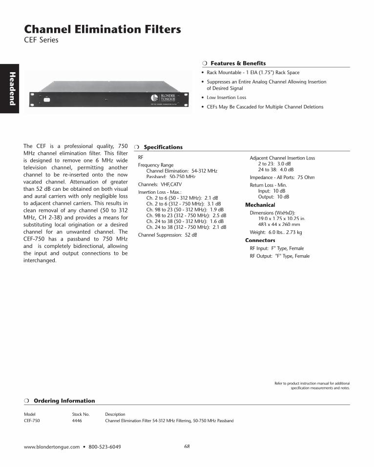
Head
end
Specifications
Ordering Information
Features & Benefits
The CEF is a professional quality, 750 MHz channel elimination filter. This filter is designed to remove one 6 MHz wide television channel, permitting another channel to be re-inserted onto the now vacated channel. Attenuation of greater than 52 dB can be obtained on both visual and aural carriers with only negligible loss to adjacent channel carriers. This results in clean removal of any channel (50 to 312 MHz, CH 2-38) and provides a means for substituting local origination or a desired channel for an unwanted channel. The CEF-750 has a passband to 750 MHz and is completely bidirectional, allowing the input and output connections to be interchanged.
RF Frequency Range Channel Elimination: 54-312 MHz Passband: 50-750 MHzChannels: VHF,CATVInsertion Loss - Max.: Ch. 2 to 6 (50 - 312 MHz): 2.1 dB Ch. 2 to 6 (312 - 750 MHz): 3.1 dB Ch. 98 to 23 (50 - 312 MHz): 1.9 dB Ch. 98 to 23 (312 - 750 MHz): 2.5 dB Ch. 24 to 38 (50 - 312 MHz): 1.6 dB Ch. 24 to 38 (312 - 750 MHz): 2.1 dBChannel Suppression: 52 dB
Adjacent Channel Insertion Loss 2 to 23: 3.0 dB 24 to 38: 4.0 dBImpedance - All Ports: 75 OhmReturn Loss - Min. Input: 10 dB Output: 10 dB
MechanicalDimensions (WxHxD): 19.0 x 1.75 x 10.25 in. 483 x 44 x 260 mmWeight: 6.0 lbs.. 2.73 kg
ConnectorsRF Input: F" Type, FemaleRF Output: "F" Type, Female
Model Stock No. DescriptionCEF-750 4446 Channel Elimination Filter 54-312 MHz Filtering, 50-750 MHz Passband
Channel Elimination Filters CEF Series
www.blondertongue.com • 800-523-6049 68
Refer to product instruction manual for additional specification measurements and notes.
• Rack Mountable - 1 EIA (1.75") Rack Space
• Suppresses an Entire Analog Channel Allowing Insertion of Desired Signal
• Low Insertion Loss
• CEFs May Be Cascaded for Multiple Channel Deletions

Hea
den
d
Tunable Notch Traps MWT Series
www.blondertongue.com • 800-523-604969
Specifications
Features & Benefits
The MWT Series are professional quality, tunable notch traps. These units are designed to trap a very narrow band of frequencies while passing the rest of the band with very low insertion loss. Two tunable traps are employed which can be tuned to the same frequency to provide up to 60 dB of attenuation. The MWT Series can be used in conjunction with an off-air antenna feed to eliminate interference (i.e. adjacent channels). The MWT Series features a rugged die cast housing and can be mast or flat surface mounted.
Ordering Information
Model Stock No. DescriptionMWT-2b 4505 Tunable Notch Trap 54-108 MHz MWT-3b 4529 Tunable Notch Trap 174-216 MHz MWT-4 4898 Tunable Notch Trap 108-174 MHz MWT-U 4614 Tunable Notch Trap 470-890 MHz
RF MWT-2b MWT-3b MWT-4 MWT-URF MWT-2b MWT-3b MWT-4 MWT-URF MWT-2b MWT-3b MWT-4 MWT-UFrequency Range MHz Trap Tuning: 54-108 174-216 108-174 470-890 Trap Tuning: 54-108 174-216 108-174 470-890 Trap Tuning: 54-108 174-216 108-174 470-890 Bandpass: 54-216 54-216 54-300 54-890 Bandpass: 54-216 54-216 54-300 54-890 Bandpass: 54-216 54-216 54-300 54-890Insertion Loss (Max) - Outside Notch dB 54-108 MHz: 1.0 1.0 1.0 1.5 54-108 MHz: 1.0 1.0 1.0 1.5 54-108 MHz: 1.0 1.0 1.0 1.5 108-174 MHz: 1.0 1.0 1.0 1.5 108-174 MHz: 1.0 1.0 1.0 1.5 108-174 MHz: 1.0 1.0 1.0 1.5 174-216 MHz: 1.0 1.0 1.0 1.5 174-216 MHz: 1.0 1.0 1.0 1.5 174-216 MHz: 1.0 1.0 1.0 1.5 470-890 MHz: NA NA NA 0.5 470-890 MHz: NA NA NA 0.5 470-890 MHz: NA NA NA 0.5Notch Depth - Maximum dB: 60 60 60 60Notch Depth - Maximum dB: 60 60 60 60Notch Depth - Maximum dB: 60 60 60 60Notch Depth Range dB: 0.5-40 0.5-40 0.5-40 NANotch Depth Range dB: 0.5-40 0.5-40 0.5-40 NANotch Depth Range dB: 0.5-40 0.5-40 0.5-40 NANotch Width dB vs. Freq.: -3 (1.9 MHz) -3 (2.0 MHz) -3 (2.0 MHz) -3 (10 MHz)Notch Width dB vs. Freq.: -3 (1.9 MHz) -3 (2.0 MHz) -3 (2.0 MHz) -3 (10 MHz)Notch Width dB vs. Freq.: -3 (1.9 MHz) -3 (2.0 MHz) -3 (2.0 MHz) -3 (10 MHz) -30 (120 kHz) -30 (100 kHz) -30 (100 kHz) -12 (3 MHz) -30 (120 kHz) -30 (100 kHz) -30 (100 kHz) -12 (3 MHz) -30 (120 kHz) -30 (100 kHz) -30 (100 kHz) -12 (3 MHz) -40 (45 kHz) -40 (35 kHz) -40 (35 kHz) -20 (1.8 MHz) -40 (45 kHz) -40 (35 kHz) -40 (35 kHz) -20 (1.8 MHz) -40 (45 kHz) -40 (35 kHz) -40 (35 kHz) -20 (1.8 MHz) -30 (400 kHz) -40 (100 kHz) -30 (400 kHz) -40 (100 kHz)Impedance - All Ports Ohm: 75 75 75 75Impedance - All Ports Ohm: 75 75 75 75Impedance - All Ports Ohm: 75 75 75 75Return Loss - Input & Output dB 54-108 MHz: 20 20 20 10 54-108 MHz: 20 20 20 10 54-108 MHz: 20 20 20 10 108-174 MHz: 20 20 20 10 108-174 MHz: 20 20 20 10 108-174 MHz: 20 20 20 10 174-216 MHz: 20 20 20 10 174-216 MHz: 20 20 20 10 174-216 MHz: 20 20 20 10 470-890 MHz: NA NA NA 15 470-890 MHz: NA NA NA 15 470-890 MHz: NA NA NA 15
GeneralPower Passing Ability: NO NO NO YES Ability: NO NO NO YES Ability: NO NO NO YES Voltage VAC: NA NA NA 100 Voltage VAC: NA NA NA 100 Voltage VAC: NA NA NA 100 Frequency Hz: NA NA NA 0-60 Frequency Hz: NA NA NA 0-60 Frequency Hz: NA NA NA 0-60 Current A: NA NA NA 6 Current A: NA NA NA 6 Current A: NA NA NA 6
Controls (Front Panel)Trap Coarse & Fine Tune: Controls Controls Controls ControlsTrap Coarse & Fine Tune: Controls Controls Controls ControlsTrap Coarse & Fine Tune: Controls Controls Controls ControlsTrap Depth: Control Control Control NATrap Depth: Control Control Control NATrap Depth: Control Control Control NA
MechanicalDimensions (LxWxD): 6.38 x 2.75 x 3.25 in
(162 x 70 x 83) mmWeight: 1.5 lbs, (0.68 kg)
Connectors (Front Panel)RF Input & Output: "F" Type Female
MWTMWT
MWT-U
• Low Insertion Loss
• VHF and UHF Tunable Notch Traps
• Ideal for Eliminating Interference from Off-Air Antennas
• Rugged Die-Cast Housing with Mast and Flat Surface Mount Ability

Head
end
Specifications
Ordering Information
Features & Benefits
The Blonder Tongue BAVM-860SAW is an economical commercial quality TV modulator. It provides a +55 dBmV RF output on any specified CATV channel from 2 to 135 (54 to 860 MHz). HRC and IRC frequency plans are also available. The BAVM-860SAW is ideal for placing A/V program sources such as satellite receivers, VCR’s, DVD’s, cameras or TV demodulators onto standard 6 MHz NTSC TV channels for broadband distribution. The BAVM-860SAW features IF SAW filtering with built-in FCC group delay pre-distortion assuring excellent adjacent channel performance and color operation. The modulator complies with FCC 21006 with +/- 5 KHz visual carrier stability and required frequency offsets on all aeronautical channels. For BTSC stereo applications, a field-defeatable audio pre-emphasis network is provided making the BAVM-860SAW compatible with any out-board stereo generator that provides a composite baseband output. A -30 dB output test point and all user controls are provided on the front panel.
RFFrequency Range: CATV Channels 2 to 135Output Level: 55 dBmV, MinOutput Level Range: 15 dB, Continuously Adjustable by Front
Panel Output Level ControlAudio/Video Carrier Ratio Control: -7 dB to -20 dB,Frequency Tolerance: ±10 kHz - Standard Channels ±5 kHz FCC 21006 OffsetsAudio Carrier Frequency Setting: ±1 kHz, Max 4.5 MHz Above Video CarrierRF to Video Response from Fv -0.5 MHz to Fv +4.2 MHz: 1 dB P/VBroadband Noise -90 dBCSpurious Output in 50 – 860 MHz Range@ +55 dBmV Output: -60 dBcOutput Match (Return Loss): 12 dBcVestigial Sideband Response: @Channel Edge -20 dB @Adjacent Channel -40 dB
VideoInput for 87.5% Modulation: 0.7V to 2.5 V P-PVideo Input Return Loss: 18 dBVideo Carrier-To-Noise Ratio in 4 MHz Bandwidth: 62 dBP-P Video to 60 Hz RMS Hum Ratio: 60 dB
Differential Gain at 87.5% Modulation: ≤ 5%Differential Phase at 87.5% Modulation: ≤ 5°Group Delay: 170 ± 50 nS
AudioInput Impedance: 10K Ohms, UnbalancedInput for 25 KHz Peak Deviation: 140 mV RMSAudio Frequency Response: ±1.0 dB (50 Hz to 15 KHz ref to std 75 msec Pre-emphasis)4.5 MHz Intercarrier Stability: ±5.0 kHz
GeneralPower Requirements: 105-130 VAC, 60 Hz, 10.5 WTemperature Range: 0 to +50 °C
MechanicalDimensions WxHxD: 19 x 13/4 x 3 inMounting: 19” Single Rack SpaceLine Cord: 3 Wire Grounded, 3 Wire Convenience OutletFinish: PlatedShipping Weight: 4 lbs. (approx)
ConnectorsAudio In: “F” Type FemaleVideo In: “F” Type FemaleRF Out: “F” Type FemaleRF Output Test - 30 dB: “F” Type Female
Model Stock No. DescriptionBAVM-860SAW 5990 300 Channelized Audio/Video Modulator, Saw Filtered 54-300 MHz BAVM-860SAW 5990 860 Channelized Audio/Video Modulator, Saw Filtered 300-860 MHz
Channelized Audio/Video Modulators BAVM-860SAW
www.blondertongue.com • 800-523-6049 70
Refer to product instruction manual for additional specification measurements and notes.
• Meets FCC Docket 21006 Aeronautical Frequency Offset Requirements
• Fully Compatible With BTSC Encoded Stereo Audio
• Front Panel Accessible Level Controls for Easy Set-Up and Adjustments
• Low Cost High Performance Channelized Audio/Video Modulator
• AC Convenience Outlet

Hea
den
d
Agile Audio/Video Demodulator ZDM-806
www.blondertongue.com • 800-523-604971
Specifications
Features & Benefits
The ZDM-806 is an agile audio/video demodulator. The ZDM-806 can demodulate any single VHF, UHF and CATV channel in the 54 to 806 MHz frequency range. It is ideal for off-air signal processing (audio/video processing and remodulation) or CATV "Cherry Picking" applications. Baseband audio and video are provided as outputs. Agile channel selection is via a front panel LED display and channel up/down buttons. A channel lockout mode is also provided to prevent accidental channel changes.
RF Frequency Range: 54-806 MHzChannels: VHF, UHF, CATVInput Level - Range: -5 to +30 dBmVNoise Figure: 8-11 dBImage Rejection VHF: 65 dB UHF: 50 dBInput/Output Impedance: 75 Ohm
VideoOutput Level: 1.0 V p-pOutput Impedance: 75 Ohm
AudioOutput Level: 1.0 V p-pImpedance - Unbalanced: 600
GeneralPower Requirements Voltage: 117, ±10% VAC Frequency: 60 Hz Power: 2.5 WTemperature Range: 0 to +50 °C
MechanicalDimensions (WxHxD): 19.0 x 1.75 x 4.00 in 483 x 44 x 102 mmWeight: 4.00 lbs, 1.82 kg
Connector (Rear Panel)RF Input: “F" Type, FemaleVideo Output: "F" Type, FemaleAudio Output: RCA Phono, female
Controls (Front Panel)Channel Selection: Push buttonsVideo Level: ControlAudio Level: Control
Indicators (Front Panel)Power ON: LED, GreenChannel: LED, 7 Segment, 3 Digit
Ordering Information
Model Stock No. DescriptionZDM-806 5880 Agile Audio/Video Demodulator 54-806 MHz UHF/VHF/CATV Input
• Rack Mountable - 1 EIA (1.75") Rack Space
• Agile Demodulator
• LED Display for Easy Channel Selection
• Superior Performance, Broadcast Applications

Head
end
Specifications
Ordering Information
Features & Benefits
The ZHC Series are professional quality, passive and active output combiners. These units are designed for use in headends to combine the outputs of multiple modulators and processors. The ZHC-12 has twelve (12) broadband input ports and one combined output port. The ZHCA-16c is a 16 port active combiner, providing over all unity gain and is commonly referred to as a "zero loss" combiner.
Model Stock No. DescriptionZHC-12a 5959A Passive Combiner 40-1000 MHz, 12 Ports ZHCA-16C-750 7757 Active Combiner 50-750 MHz, 16 Ports
Combiners ZHC Series
www.blondertongue.com • 800-523-6049 72
RF ZHC-12a ZHCA-16cNumber of Inputs: 12 16Frequency Range MHz: 40-1000 54-750Input Level - Max dBmV: NA +57Output Level - Max dBmV: NA +48Cross Modulation dBc: NA -57Overall Unit Gain dB: NA 0 to -3Gain Control Range dB: NA 9Insertion Loss dB: 40-450 MHz 17 dB NA 450-1000 MHz 20 dBIsolation dB: 30 40Flatness dB: 3 3Impedance - All Ports Ohm: 75 75
GeneralPower Requirements Voltage VAC: NA 117 ± 10% Frequency Hz: NA 60 Power W: NA 10Temperature Range °C: NA 0 to +50
MechanicalDimensions (WxHxD): 19.0 x 1.75 x 2.88 in. 19.0 x 1.75 x 2.88 in. 483 x 44 x 73 mm 483 x 44 x 73 mmWeight lbs: 2.0 lbs., 0.91 kg. 3.0 lbs., 1.36 kg.
Connectors (Rear Panel)RF Input & Output: "F" Type Female "F" Type FemaleConnectors (Front Panel)Test Port: "F" Type Female "F" Type Female
Controls (Front Panel)Gain: NA Control
Refer to product instruction manual for additional specification measurements and notes.
• Rack Mountable - 1 EIA (1.75") Rack Space
• High Isolation
• -20 dB Test Port

Hea
den
d
Channel Converters MCX-Uz Series
www.blondertongue.com • 800-523-604973
Specifications
Features & Benefits
The MCX-Uz is a low cost, professional quality, single channel converter. This unit is designed for use in commercial grade, MATV or SMATV headends. The MCX-Uz features single conversion circuitry for channel changes, eliminating the need for double conversion or external traps and filters. Some channel conversions are forbidden (see chart) and will require the double conversion process used in Blonder Tongue’s CAP Series (Channelized Heterodyne Processor) or SAIP Series (Agile Input, Channelized Agile Output Heterodyne Processor). The MCX-Uz converts any UHF channel (470 to 806 MHz) to any VHF channel in the 50 to 216 MHz frequency range (with exceptions). These converters feature crystal controlled PLL synthesizers and a balanced mixer design, thereby allowing operation in adjacent channel systems. The unit is both electrically and mechanically compatible with Blonder Tongue’s Low Cost Single Channel VHF Strip Amplifier (ZSCA) and Bandpass Filter (BPF-z).
RFFrequency Range Input: 470-806 MHz Output: 50-216 MHzFlatness: 0.8 dBInput Signal Level Minimum: -4.0 dBmV Gain: 20 dB Gain Control Range: 10 dBNoise Figure: 9.0 dB Frequency Stability: ±15 kHzSelectivity ±9 MHz: -25 dB ±21 MHz: -50 dBSpurious Outputs - L.O. Related At Output: -38 dBmV At Input: -30 dBmVImage Rejection: -55 dBHum Modulation: -60 dBImpedance - All Ports: 75 OhmReturn Loss Input: 14 dB Output: 14 dB
GeneralPower Requirements Voltage: 117, ±10% VAC Frequency: 60 Hz Power: 12 WTemperature Range: -20 to +50 °C
MechanicalDimensions (WxHxD): 19.0 x 1.75 x 2.00 in. 483 x 44 x 51 mmWeight: 4.0 lbs., 1.82 kg
Connectors (Rear Panel)RF Input: “F” Type, FemaleRF Output: “F” Type, Female
Connectors (Front Panel)Test Port: “F” Type, Female
Controls (Front Panel)RF Output Level: Control
Indicators (Front Panel)Power ON: LED, Green
Ordering Information
Model Stock No. DescriptionMCX-UZ 1479 Channel Converter 470-806 MHz (UHF), 50-220 MHz (VHF)
Refer to product instruction manual for additional specification measurements and notes.
• Rack Mountable - 1 EIA (1.75") Rack Space
• UHF to VHF Channel Conversion
• Crystal Controlled PLL Synthesizer Permits Use in Adjacent Channel Systems
• Balanced Mixer Design Provides Maximum Isolation Between Local Oscillator, Input and Output
• Excellent Image Rejection Characteristics
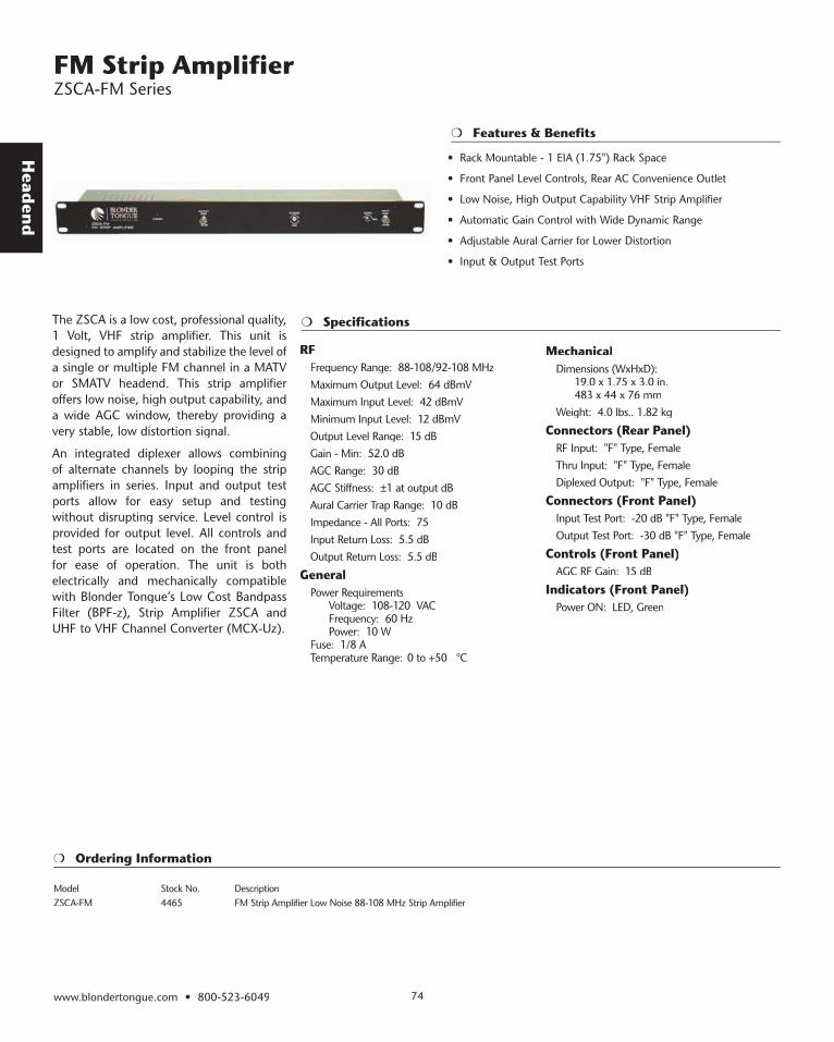
Head
end
Specifications
Features & Benefits
FM Strip Amplifi er ZSCA-FM Series
The ZSCA is a low cost, professional quality, 1 Volt, VHF strip amplifier. This unit is designed to amplify and stabilize the level of a single or multiple FM channel in a MATV or SMATV headend. This strip amplifier offers low noise, high output capability, and a wide AGC window, thereby providing a very stable, low distortion signal.
An integrated diplexer allows combining of alternate channels by looping the strip amplifiers in series. Input and output test ports allow for easy setup and testing without disrupting service. Level control is provided for output level. All controls and test ports are located on the front panel for ease of operation. The unit is both electrically and mechanically compatible with Blonder Tongue’s Low Cost Bandpass Filter (BPF-z), Strip Amplifier ZSCA and UHF to VHF Channel Converter (MCX-Uz) .
RFFrequency Range: 88-108/92-108 MHzMaximum Output Level: 64 dBmVMaximum Input Level: 42 dBmVMinimum Input Level: 12 dBmVOutput Level Range: 15 dBGain - Min: 52.0 dBAGC Range: 30 dBAGC Stiffness: ±1 at output dBAural Carrier Trap Range: 10 dBImpedance - All Ports: 75 Input Return Loss: 5.5 dBOutput Return Loss: 5.5 dB
GeneralPower Requirements Voltage: 108-120 VAC Frequency: 60 Hz Power: 10 WFuse: 1/8 ATemperature Range: 0 to +50 °C
MechanicalDimensions (WxHxD): 19.0 x 1.75 x 3.0 in. 483 x 44 x 76 mmWeight: 4.0 lbs.. 1.82 kg
Connectors (Rear Panel)RF Input: "F" Type, FemaleThru Input: "F" Type, FemaleDiplexed Output: "F" Type, Female
Connectors (Front Panel)Input Test Port: -20 dB "F" Type, FemaleOutput Test Port: -30 dB "F" Type, Female
Controls (Front Panel)AGC RF Gain: 15 dB
Indicators (Front Panel)Power ON: LED, Green
Ordering Information
Model Stock No. DescriptionZSCA-FM 4465 FM Strip Amplifier Low Noise 88-108 MHz Strip Amplifier
www.blondertongue.com • 800-523-6049 74
• Rack Mountable - 1 EIA (1.75") Rack Space
• Front Panel Level Controls, Rear AC Convenience Outlet
• Low Noise, High Output Capability VHF Strip Amplifier
• Automatic Gain Control with Wide Dynamic Range
• Adjustable Aural Carrier for Lower Distortion
• Input & Output Test Ports
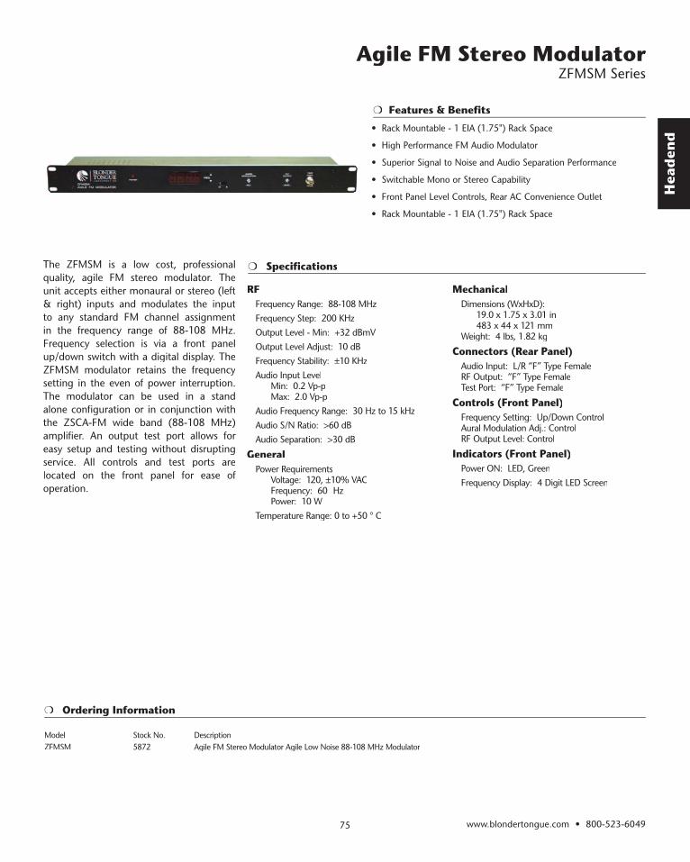
Hea
den
d
Specifications
Ordering Information
Features & Benefits
Agile FM Stereo Modulator ZFMSM Series
The ZFMSM is a low cost, professional quality, agile FM stereo modulator. The unit accepts either monaural or stereo (left & right) inputs and modulates the input to any standard FM channel assignment in the frequency range of 88-108 MHz. Frequency selection is via a front panel up/down switch with a digital display. The ZFMSM modulator retains the frequency setting in the even of power interruption. The modulator can be used in a stand alone configuration or in conjunction with the ZSCA-FM wide band (88-108 MHz) amplifier. An output test port allows for easy setup and testing without disrupting service. All controls and test ports are located on the front panel for ease of operation.
RFFrequency Range: 88-108 MHzFrequency Step: 200 KHzOutput Level - Min: +32 dBmVOutput Level Adjust: 10 dBFrequency Stability: ±10 KHzAudio Input Level Min: 0.2 Vp-p Max: 2.0 Vp-pAudio Frequency Range: 30 Hz to 15 kHzAudio S/N Ratio: >60 dBAudio Separation: >30 dB
GeneralPower Requirements Voltage: 120, ±10% VAC Frequency: 60 Hz Power: 10 WTemperature Range: 0 to +50 ° C
MechanicalDimensions (WxHxD): 19.0 x 1.75 x 3.01 in 483 x 44 x 121 mmWeight: 4 lbs, 1.82 kg
Connectors (Rear Panel)Audio Input: L/R “F” Type FemaleRF Output: “F” Type FemaleTest Port: “F” Type Female
Controls (Front Panel)Frequency Setting: Up/Down ControlAural Modulation Adj.: ControlRF Output Level: Control
Indicators (Front Panel)Power ON: LED, GreenFrequency Display: 4 Digit LED Screen
Model Stock No. DescriptionZFMSM 5872 Agile FM Stereo Modulator Agile Low Noise 88-108 MHz Modulator
www.blondertongue.com • 800-523-604975
• Rack Mountable - 1 EIA (1.75") Rack Space
• High Performance FM Audio Modulator
• Superior Signal to Noise and Audio Separation Performance
• Switchable Mono or Stereo Capability
• Front Panel Level Controls, Rear AC Convenience Outlet
• Rack Mountable - 1 EIA (1.75") Rack Space
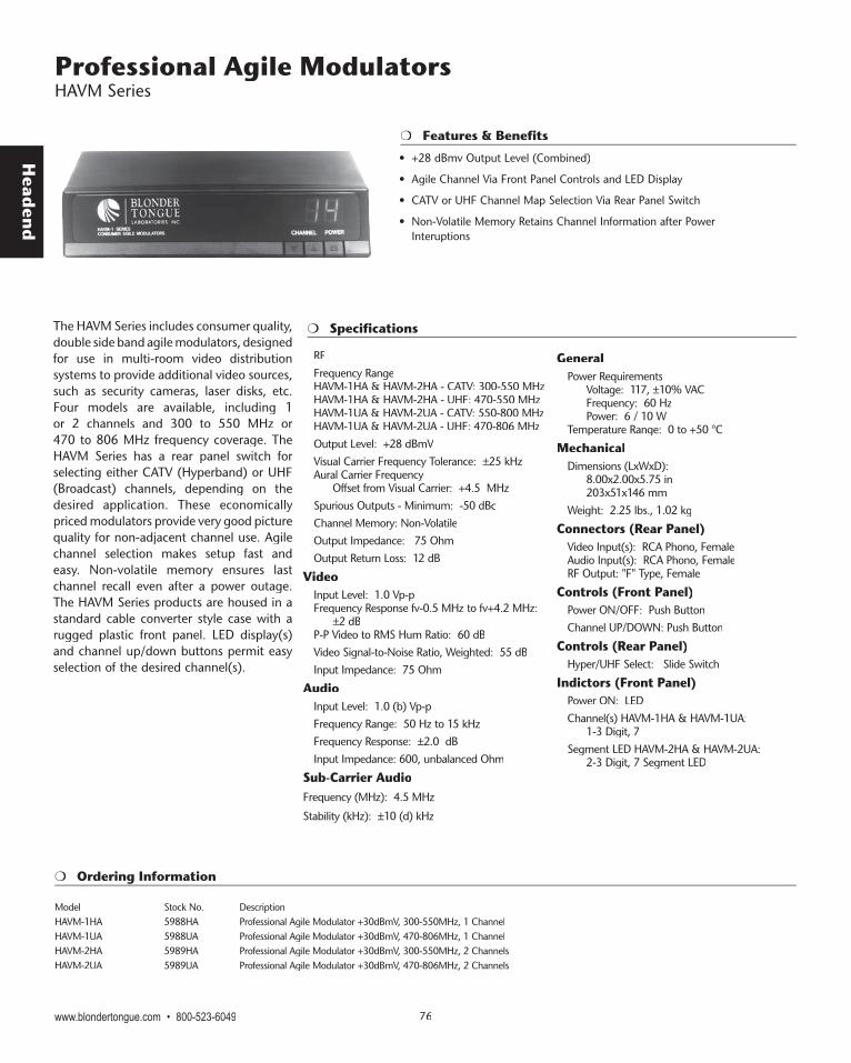
Head
end
Specifications
Features & Benefits
Professional Agile Modulators HAVM Series
The HAVM Series includes consumer quality, double side band agile modulators, designed for use in multi-room video distribution systems to provide additional video sources, such as security cameras, laser disks, etc. Four models are available, including 1 or 2 channels and 300 to 550 MHz or 470 to 806 MHz frequency coverage. The HAVM Series has a rear panel switch for selecting either CATV (Hyperband) or UHF (Broadcast) channels, depending on the desired application. These economically priced modulators provide very good picture quality for non-adjacent channel use. Agile channel selection makes setup fast and easy. Non-volatile memory ensures last channel recall even after a power outage. The HAVM Series products are housed in a standard cable converter style case with a rugged plastic front panel. LED display(s) and channel up/down buttons permit easy selection of the desired channel(s).
RFFrequency RangeHAVM-1HA & HAVM-2HA - CATV: 300-550 MHzHAVM-1HA & HAVM-2HA - UHF: 470-550 MHzHAVM-1UA & HAVM-2UA - CATV: 550-800 MHzHAVM-1UA & HAVM-2UA - UHF: 470-806 MHzOutput Level: +28 dBmVVisual Carrier Frequency Tolerance: ±25 kHzAural Carrier Frequency Offset from Visual Carrier: +4.5 MHzSpurious Outputs - Minimum: -50 dBcChannel Memory: Non-VolatileOutput Impedance: 75 OhmOutput Return Loss: 12 dB
VideoInput Level: 1.0 Vp-pFrequency Response fv-0.5 MHz to fv+4.2 MHz: ±2 dBP-P Video to RMS Hum Ratio: 60 dBVideo Signal-to-Noise Ratio, Weighted: 55 dBInput Impedance: 75 Ohm
AudioInput Level: 1.0 (b) Vp-pFrequency Range: 50 Hz to 15 kHzFrequency Response: ±2.0 dBInput Impedance: 600, unbalanced Ohm
Sub-Carrier AudioFrequency (MHz): 4.5 MHz
Stability (kHz): ±10 (d) kHz
GeneralPower Requirements Voltage: 117, ±10% VAC Frequency: 60 Hz Power: 6 / 10 WTemperature Range: 0 to +50 °C
MechanicalDimensions (LxWxD): 8.00x2.00x5.75 in 203x51x146 mmWeight: 2.25 lbs., 1.02 kg
Connectors (Rear Panel)Video Input(s): RCA Phono, FemaleAudio Input(s): RCA Phono, FemaleRF Output: "F" Type, Female
Controls (Front Panel)Power ON/OFF: Push ButtonChannel UP/DOWN: Push Button
Controls (Rear Panel)Hyper/UHF Select: Slide Switch
Indictors (Front Panel)Power ON: LEDChannel(s) HAVM-1HA & HAVM-1UA: 1-3 Digit, 7Segment LED HAVM-2HA & HAVM-2UA: 2-3 Digit, 7 Segment LED
Ordering Information
Model Stock No. DescriptionHAVM-1HA 5988HA Professional Agile Modulator +30dBmV, 300-550MHz, 1 Channel HAVM-1UA 5988UA Professional Agile Modulator +30dBmV, 470-806MHz, 1 Channel HAVM-2HA 5989HA Professional Agile Modulator +30dBmV, 300-550MHz, 2 Channels HAVM-2UA 5989UA Professional Agile Modulator +30dBmV, 470-806MHz, 2 Channels
www.blondertongue.com • 800-523-6049 76
• +28 dBmv Output Level (Combined)
• Agile Channel Via Front Panel Controls and LED Display
• CATV or UHF Channel Map Selection Via Rear Panel Switch
• Non-Volatile Memory Retains Channel Information after Power Interuptions
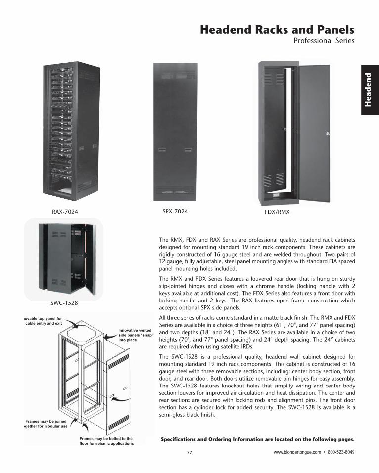
Hea
den
d
Headend Racks and Panels Professional Series
www.blondertongue.com • 800-523-604977
The RMX, FDX and RAX Series are professional quality, headend rack cabinets designed for mounting standard 19 inch rack components. These cabinets are rigidly constructed of 16 gauge steel and are welded throughout. Two pairs of 12 gauge, fully adjustable, steel panel mounting angles with standard EIA spaced panel mounting holes included.
The RMX and FDX Series features a louvered rear door that is hung on sturdy slip-jointed hinges and closes with a chrome handle (locking handle with 2 keys available at additional cost). The FDX Series also features a front door with locking handle and 2 keys. The RAX features open frame construction which accepts optional SPX side panels.
All three series of racks come standard in a matte black finish. The RMX and FDX Series are available in a choice of three heights (61", 70", and 77" panel spacing) and two depths (18" and 24"). The RAX Series are available in a choice of two heights (70", and 77" panel spacing) and 24" depth spacing. The 24” cabinets are required when using satellite IRDs.
The SWC-1528 is a professional quality, headend wall cabinet designed for mounting standard 19 inch rack components. This cabinet is constructed of 16 gauge steel with three removable sections, including: center body section, front door, and rear door. Both doors utilize removable pin hinges for easy assembly. The SWC-1528 features knockout holes that simplify wiring and center body section louvers for improved air circulation and heat dissipation. The center and rear sections are secured with locking rods and alignment pins. The front door section has a cylinder lock for added security. The SWC-1528 is available is a semi-gloss black finish.
Removable top panel forcable entry and exit
Innovative ventedside panels "snap" into place
Frames may be bolted to the floor for seismic applications
Frames may be joined together for modular use
RAX-7024 SPX-7024
SWC-1528SWC-1528
FDX/RMX
Specifications and Ordering Information are located on the following pages.
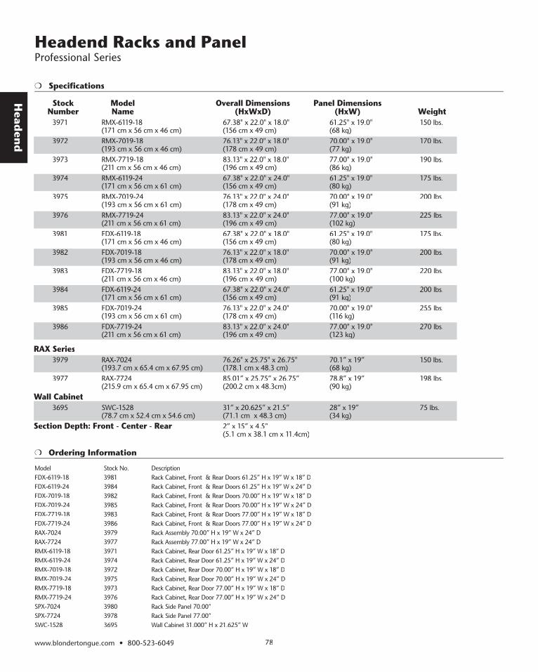
Head
end
Specifications
Headend Racks and Panel Professional Series
www.blondertongue.com • 800-523-6049 78
Stock Model Overall Dimensions Panel Dimensions Number Name (HxWxD) (HxW) Weight
3971 RMX-6119-18 67.38" x 22.0" x 18.0" 61.25" x 19.0" 150 lbs. (171 cm x 56 cm x 46 cm) (156 cm x 49 cm) (68 kg) 3972 RMX-7019-18 76.13" x 22.0" x 18.0" 70.00" x 19.0" 170 lbs. (193 cm x 56 cm x 46 cm) (178 cm x 49 cm) (77 kg) 3973 RMX-7719-18 83.13" x 22.0" x 18.0" 77.00" x 19.0" 190 lbs. (211 cm x 56 cm x 46 cm) (196 cm x 49 cm) (86 kg) 3974 RMX-6119-24 67.38" x 22.0" x 24.0" 61.25" x 19.0" 175 lbs. (171 cm x 56 cm x 61 cm) (156 cm x 49 cm) (80 kg) 3975 RMX-7019-24 76.13" x 22.0" x 24.0" 70.00" x 19.0" 200 lbs. (193 cm x 56 cm x 61 cm) (178 cm x 49 cm) (91 kg) 3976 RMX-7719-24 83.13" x 22.0" x 24.0" 77.00" x 19.0" 225 lbs. (211 cm x 56 cm x 61 cm) (196 cm x 49 cm) (102 kg) 3981 FDX-6119-18 67.38" x 22.0" x 18.0" 61.25" x 19.0" 175 lbs. (171 cm x 56 cm x 46 cm) (156 cm x 49 cm) (80 kg) 3982 FDX-7019-18 76.13" x 22.0" x 18.0" 70.00" x 19.0" 200 lbs. (193 cm x 56 cm x 46 cm) (178 cm x 49 cm) (91 kg) 3983 FDX-7719-18 83.13" x 22.0" x 18.0" 77.00" x 19.0" 220 lbs. (211 cm x 56 cm x 46 cm) (196 cm x 49 cm) (100 kg) 3984 FDX-6119-24 67.38" x 22.0" x 24.0" 61.25" x 19.0" 200 lbs. (171 cm x 56 cm x 61 cm) (156 cm x 49 cm) (91 kg) 3985 FDX-7019-24 76.13" x 22.0" x 24.0" 70.00" x 19.0" 255 lbs. (193 cm x 56 cm x 61 cm) (178 cm x 49 cm) (116 kg) 3986 FDX-7719-24 83.13" x 22.0" x 24.0" 77.00" x 19.0" 270 lbs. (211 cm x 56 cm x 61 cm) (196 cm x 49 cm) (123 kg)
RAX Series 3979 RAX-7024 76.26" x 25.75" x 26.75" 70.1” x 19” 150 lbs. (193.7 cm x 65.4 cm x 67.95 cm) (178.1 cm x 48.3 cm) (68 kg) 3977 RAX-7724 85.01” x 25.75” x 26.75” 78.8” x 19” 198 lbs. (215.9 cm x 65.4 cm x 67.95 cm) (200.2 cm x 48.3cm) (90 kg)
Wall Cabinet 3695 SWC-1528 31” x 20.625” x 21.5” 28” x 19” 75 lbs. (78.7 cm x 52.4 cm x 54.6 cm) (71.1 cm x 48.3 cm) (34 kg)
Section Depth: Front - Center - Rear 2” x 15” x 4.5” (5.1 cm x 38.1 cm x 11.4cm)
Model Stock No. DescriptionFDX-6119-18 3981 Rack Cabinet, Front & Rear Doors 61.25” H x 19” W x 18” D FDX-6119-24 3984 Rack Cabinet, Front & Rear Doors 61.25” H x 19” W x 24” D FDX-7019-18 3982 Rack Cabinet, Front & Rear Doors 70.00” H x 19” W x 18” D FDX-7019-24 3985 Rack Cabinet, Front & Rear Doors 70.00” H x 19” W x 24” D FDX-7719-18 3983 Rack Cabinet, Front & Rear Doors 77.00” H x 19” W x 18” D FDX-7719-24 3986 Rack Cabinet, Front & Rear Doors 77.00” H x 19” W x 24” D RAX-7024 3979 Rack Assembly 70.00” H x 19” W x 24” D RAX-7724 3977 Rack Assembly 77.00” H x 19” W x 24” D RMX-6119-18 3971 Rack Cabinet, Rear Door 61.25” H x 19” W x 18” D RMX-6119-24 3974 Rack Cabinet, Rear Door 61.25” H x 19” W x 24” D RMX-7019-18 3972 Rack Cabinet, Rear Door 70.00” H x 19” W x 18” D RMX-7019-24 3975 Rack Cabinet, Rear Door 70.00” H x 19” W x 24” D RMX-7719-18 3973 Rack Cabinet, Rear Door 77.00” H x 19” W x 18” D RMX-7719-24 3976 Rack Cabinet, Rear Door 77.00” H x 19” W x 24” D SPX-7024 3980 Rack Side Panel 70.00” SPX-7724 3978 Rack Side Panel 77.00” SWC-1528 3695 Wall Cabinet 31.000” H x 21.625” W
Ordering Information

Hea
den
d
www.blondertongue.com • 800-523-604979
Headend Racks and Panel Economy Series
20 7/8"
16"
(Standard Stud Spacing)
19" Rack Frame
Depth of IRH-1924b-Fis 6 1/4"
Perforated
Perforated
IRH-1924b-CLocking Cover
Tumbler Lock
2 3/4"
28 3/4"
24 1/2"Panel Space
IRH-1924B-CIRH-1924B-F
The IRH Series are professional quality, headend rack products designed for wall mounting standard 19 inch rack components. Three components are available, including: IRH-1924B-F, rack frame; IRH-1924B-C, locking cover; and IRH PANEL, perforated panel.
The RR Series are professional quality, headend relay racks designed for mounting standard 19 inch rack components. The RR-2164, RR-2173, and RR-2180 are heavy duty, very rugged relays racks with 8" side rails. The RR-6119-3, RR-7019-3 and RR-8419-3 are economical, rugged relays racks with 3" side rails.
Ordering Information
Model Stock No. DescriptionIRH-1924B-F 3690 Rack Frame 19” W x 24” H x 2.75” DIRH-1924B-C 3691 Rack Frame, Locking Cover
Ordering Information
Model Stock No. DescriptionRR-6119-3 3960 3 Relay Rack 61.25” H x 22” W x 3” D RR-7019-3 3970 3 Relay Rack 70.00” H x 22” W x 3” D RR-8419-3 3950 3 Relay Rack 83.50” H x 22” W x 3” D RR-2180 3963 Relay Rack 80.25” H x 22” W x 8” D, Heavy Duty RR-2164 3961 Relay Rack 64.50” H x 22” W x 8” D, Heavy Duty RR-2173 3962 Relay Rack 73.25” H x 22” W x 8” D, Heavy Duty
Mechanical RR-2164 RR-2173 RR-2180 RR-6119-3 RR-7019-3 Mechanical RR-2164 RR-2173 RR-2180 RR-6119-3 RR-7019-3 Mechanical RR-2164 RR-2173 RR-2180 RR-6119-3 RR-7019-3 RR-8419-3
Dimensions (HxWxD) in: 64.50 x 73.25 x 80.25 x 61.25 x 70.00 x in: 64.50 x 73.25 x 80.25 x 61.25 x 70.00 x in: 64.50 x 73.25 x 80.25 x 61.25 x 70.00 x 83.50 x 22 x 8.13 22 x 8.13 22 x 8.13 22 x 3.00 22 x 3.00 22 x 8.13 22 x 8.13 22 x 8.13 22 x 3.00 22 x 3.00 22 x 8.13 22 x 8.13 22 x 8.13 22 x 3.00 22 x 3.00 22 x 3.00Dimensions (HxWxD) cm: 164 x 56 x 21 186 x 56 x 21 204 x 56 x 21 156 x 56 x 8 178 x 56 x 8 cm: 164 x 56 x 21 186 x 56 x 21 204 x 56 x 21 156 x 56 x 8 178 x 56 x 8 cm: 164 x 56 x 21 186 x 56 x 21 204 x 56 x 21 156 x 56 x 8 178 x 56 x 8 212 x 56 x 8
Weight lbs: 85.0 90.0 95.0 37.0 41.0 43 lbs: 85.0 90.0 95.0 37.0 41.0 43 lbs: 85.0 90.0 95.0 37.0 41.0 43 lbs: 85.0 90.0 95.0 37.0 41.0 43 kg: 38.64 40.91 43.18 16.82 18.64 19.5 kg: 38.64 40.91 43.18 16.82 18.64 19.5 kg: 38.64 40.91 43.18 16.82 18.64 19.5 kg: 38.64 40.91 43.18 16.82 18.64 19.5
Specifications
Heavy Duty RacksHeavy Duty Racks
EcoEcoEconomynomy Racks Racks

Head
end
Headend Racks and Panel Economy Series
www.blondertongue.com • 800-523-6049 80
BH-1
Dimensions: 20.0" x 27.0" x 10.5" inches
51 cm x 69 cm x 27 cmWeight: 18 lbs., 8.18 kg
The BH-1 is a professional quality housing designed for enclosing equipment in an indoor environment. This housing is an indoor, fully ventilated housing with a perforated mounting surface. Keyed slots allow both vertical and horizontal mounting.
The BFP Series includes black anodized blank panels used to finish the professional look of a Blonder Tongue headend. These panels have an identical look and finish as standard Blonder Tongue headend products. Three models are available, including: BFP-119 BLK, 1.75"; BFP-319 BLK, 3.50"; and BFP-519, 5.25".
Specifications
Ordering Information
Model Stock No. DescriptionBFP19-3B 3991B Blank Front Panel Black, 19” W x 5.25” H (3 Rack Unit High) BFP-19-V 3988 Vented Blank Front Panel Black, 19” W x 1.75” H (1 Rack Unit High) BFP19-2B 3990B Blank Front Panel Black, 19” W x 3.50” H (2 Rack Unit High) BFP19-1B 3989B Blank Front Panel Black, 19” W x 1.75” H (1 Rack Unit High) RR-6/8 RX 3932E Universal 19 inch Satellite Receiver Rack (Holds 6 or 8 Satellite Receivers) IRH PANEL 3693 Perforated Panel, 19" W x 5.25" H RS-2U 3995 Rack Shelf (2 Rack Unit High)
Panels
IRH PanelIRH Panel
BPF-19-1V
RR-6/8 RX
The RR-6/8 RX is a universal 19 inch satellite receiver rack which holds up 6 or 8 satellite receivers (model dependent).
2 RU Shelf

Hea
den
d
www.blondertongue.com • 800-523-604981
Specifications
Ordering Information
Features & Benefits
Modern school systems often incorporate audio (paging or intercom throughout the school) with traditional video distribution (delivering a number of channels to each classroom). Video distribution allows the school to interface with local cable television and deliver topical programs to each class-room, originate local programming (either live or playback via a VCR) and provide to every room in the school. Additionally, emergency or general announcement information can be quickly delivered with both audio and video information to each television in the school. Blonder Tongue manufactures a complete line of products for implementing a Video All-Call System. These systems provide an integrated solution of allowing one channel to override all other channels on all televisions in a school system. In order to integrate all of these components into a complete all-call system, Blonder Tongue also offers the VACD- 12 Distribution Amplifier and the AB-800 Pin Diode Switch. These two products are used to distribute the alternate audio/video program to each modulator and processor in the system. When invoked, the substitute IF program will override the normal IF programs available at each modulator and processor. Every channel in the system will be overridden with the new program.
VACD-12IF
Input Frequency Range: 41 to 47 MHzInput/Output Level: +28 dBmVReserve Gain: 3 dBOutput Frequency Range: 41 to 47 MHz
ElectricalAB-800 Control Voltages: ±15 VDCSensing: Contact Closure
GeneralPower Requirements Voltage: 117, ±10% VAC Frequency: 60 Hz Power: 12 WFuse: 1/2 ATemperature Range: 0 to +50 °C
MechanicalDimensions (WxHxD): 19.0 x 1.75 x 15.25 in 483 x 44 x 387 mmWeight: 11.00 lbs. (5.00 kg)
Connectors (Rear Panel)IF IN: "F" Type, FemaleIF OUTs (12): "F" Type, FemaleControl: MOLEX, Female, 4 PINSense: MOLEX, Female, 2 PIN
Connectors (Front Panel)IF Test Port: "F" type, female
Controls (Front Panel) IF Output Level: Control
IndicatorsPower ON: LED, Green
AccessoriesControl Plug Pigtail: MOLEX, 4 PIN, male
AB-800IF
Input Frequency Range: 41 to 47 MHzInsertion Loss: 0.5 dBIsolation: >60 dB
ElectricalControl Voltages: ±15 VDC
MechanicalDimensions (WxHxD): 4.44 x 1.56 x 0.94 in 113 x 40 x 24 mmWeight: 1.00 lbs. (0.45 kg)
Connectors (Side Panels)IF Input: "F" Type, FemaleAll-Call Input: "F" Type, FemaleIF Output: "F" Type, FemaleControl: Locking Header, Female, 4 PIN
AccessoriesControl Plug: Locking Plug, Male, 4 PIN
Model Stock No. DescriptionVACD-12 4019 Video All-Call Distribution Amplifier NOTE: Use with AB-800 AB-800 4018 A/B Pin Diode Switch
Video All-Call Systems VACD-12 AND AB-800
• Video All-Call System - Provides Override of All Channels on the System
• Compatible with CATV or Off-Air Systems
• Distributes Signals Throughput Installation Including Locally Originated Signals
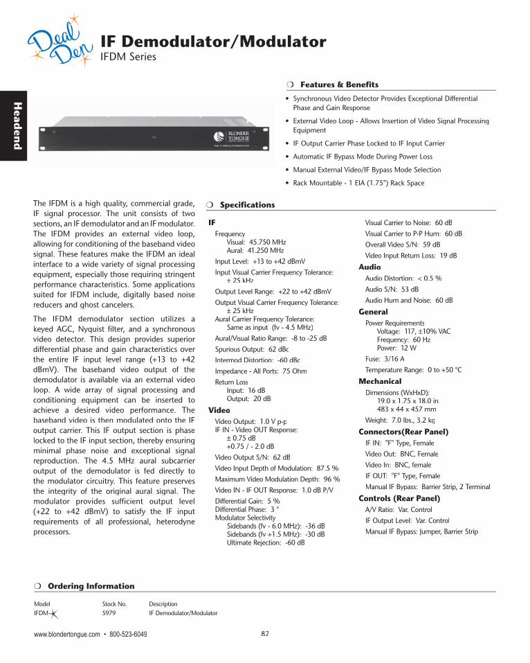
Head
end
www.blondertongue.com • 800-523-6049 82
Specifications
Features & Benefits
IF Demodulator/Modulator IFDM Series
The IFDM is a high quality, commercial grade, IF signal processor. The unit consists of two sections, an IF demodulator and an IF modulator. The IFDM provides an external video loop, allowing for conditioning of the baseband video signal. These features make the IFDM an ideal interface to a wide variety of signal processing equipment, especially those requiring stringent performance characteristics. Some applications suited for IFDM include, digitally based noise reducers and ghost cancelers.
The IFDM demodulator section utilizes a keyed AGC, Nyquist filter, and a synchronous video detector. This design provides superior differential phase and gain characteristics over the entire IF input level range (+13 to +42 dBmV). The baseband video output of the demodulator is available via an external video loop. A wide array of signal processing and conditioning equipment can be inserted to achieve a desired video performance. The baseband video is then modulated onto the IF output carrier. This IF output section is phase locked to the IF input section, thereby ensuring minimal phase noise and exceptional signal reproduction. The 4.5 MHz aural subcarrier output of the demodulator is fed directly to the modulator circuitry. This feature preserves the integrity of the original aural signal. The modulator provides sufficient output level (+22 to +42 dBmV) to satisfy the IF input requirements of all professional, heterodyne processors.
IFFrequency Visual: 45.750 MHz Aural: 41.250 MHzInput Level: +13 to +42 dBmVInput Visual Carrier Frequency Tolerance: ± 25 kHzOutput Level Range: +22 to +42 dBmVOutput Visual Carrier Frequency Tolerance: ± 25 kHzAural Carrier Frequency Tolerance: Same as input (fv - 4.5 MHz)Aural/Visual Ratio Range: -8 to -25 dBSpurious Output: 62 dBc Intermod Distortion: -60 dBc Impedance - All Ports: 75 OhmReturn Loss Input: 16 dB Output: 20 dB
VideoVideo Output: 1.0 V p-pIF IN - Video OUT Response: ± 0.75 dB +0.75 / - 2.0 dBVideo Output S/N: 62 dBVideo Input Depth of Modulation: 87.5 %Maximum Video Modulation Depth: 96 %Video IN - IF OUT Response: 1.0 dB P/V Differential Gain: 5 %Differential Phase: 3 °Modulator Selectivity Sidebands (fv - 6.0 MHz): -36 dB Sidebands (fv +1.5 MHz): -30 dB Ultimate Rejection: -60 dB
Visual Carrier to Noise: 60 dBVisual Carrier to P-P Hum: 60 dBOverall Video S/N: 59 dBVideo Input Return Loss: 19 dB
AudioAudio Distortion: < 0.5 %Audio S/N: 53 dBAudio Hum and Noise: 60 dB
GeneralPower Requirements Voltage: 117, ±10% VAC Frequency: 60 Hz Power: 12 WFuse: 3/16 ATemperature Range: 0 to +50 °C
MechanicalDimensions (WxHxD): 19.0 x 1.75 x 18.0 in. 483 x 44 x 457 mmWeight: 7.0 lbs., 3.2 kg
Connectors(Rear Panel)IF IN: "F" Type, FemaleVideo Out: BNC, FemaleVideo In: BNC, femaleIF OUT: "F" Type, FemaleManual IF Bypass: Barrier Strip, 2 Terminal
Controls (Rear Panel)A/V Ratio: Var. ControlIF Output Level: Var. ControlManual IF Bypass: Jumper, Barrier Strip
Ordering Information
Model Stock No. DescriptionIFDM 5979 IF Demodulator/Modulator
• Synchronous Video Detector Provides Exceptional Differential Phase and Gain Response
• External Video Loop - Allows Insertion of Video Signal Processing Equipment
• IF Output Carrier Phase Locked to IF Input Carrier
• Automatic IF Bypass Mode During Power Loss
• Manual External Video/IF Bypass Mode Selection
• Rack Mountable - 1 EIA (1.75") Rack Space