health & safety guidelines - zendesk · health & safety guidelines. ... machine safety and...
TRANSCRIPT

Health & Safety Guidelines
TABLE OF CONTENTS INTRODUCTION ............................................................................................................................................... 4 HEALTH AND SAFETY GUIDELINES – BASIC H&S GUIDELINES ............................................................. 5 SECTION 1 – MANAGEMENT ......................................................................................................................... 6
1.1 DOCUMENTATION GUIDELINES FOR FACTORY MANAGEMENT .............................................................. 6 1.2 ACCIDENT/INJURY LOG..................................................................................................................... 7 1.3 FIRE AND EMERGENCY PREPAREDNESS PLAN ................................................................................... 7
SECTION 2 – ARCHITECTURAL CONSIDERATIONS .................................................................................... 9 2.1 GUIDELINES ON STRUCTURAL COMPONENTS OF FACTORY BUILDINGS ................................................ 9 2.2 FIRE AND SAFETY ISSUES RELATED TO BUILDING CONSTRUCTION...................................................... 9 2.3 GENERAL FIRE SAFETY ................................................................................................................... 10 2.4 AISLES AND EMERGENCY EGRESS ROUTES ...................................................................................... 11 2.5 STAIRWAYS..................................................................................................................................... 12 2.6 EXITS ............................................................................................................................................. 13 2.7 TRAVEL DISTANCE .......................................................................................................................... 13
SECTION 3 – FIRE SAFETY .......................................................................................................................... 15 3.1 FIRE SAFETY GUIDELINES ............................................................................................................... 15 3.2 FIRE EVACUATION DRILLS............................................................................................................... 16 3.3 BACKGROUND INFORMATION ON THE DEVELOPMENT AND PROPAGATION OF FIRES ........................... 17 3.4 FIRE PREVENTION STRATEGY.......................................................................................................... 18 3.5 FIRE EXTINGUISHING STRATEGY ...................................................................................................... 18 3.6 FIRE FIGHTING STRATEGY ............................................................................................................... 19 3.7 GUIDELINES ON DISTRIBUTION AND USE OF PORTABLE FIRE EXTINGUISHERS................................... 23 3.8 COLOUR CODING FIRE EXTINGUISHERS ........................................................................................... 23 3.9 WORKER TRAINING ON ASPECTS OF FIRE SAFETY ............................................................................ 24 3.10 EXIT SIGNS/EMERGENCY ILLUMINATION .......................................................................................... 25
SECTION 4 – FIRST AID ................................................................................................................................ 27 4.1 GUIDELINES FOR FIRST AID............................................................................................................. 27
SECTION 5 – CHEMICAL SAFETY MANAGEMENT .................................................................................... 29 5.1 INFORMATION ON THE HAZARDS ASSOCIATED WITH CHEMICAL MATERIALS....................................... 29
5.1.1 Health Hazards ....................................................................................................................... 29 5.1.2 Physical Hazards .................................................................................................................... 30
5.2 MATERIAL SAFETY DATA SHEETS (MSDS) ...................................................................................... 31 5.3 CHEMICAL SAFETY DATA SHEETS (CSDS)....................................................................................... 31 5.4 STORAGE OF HAZARDOUS MATERIALS ............................................................................................. 32 5.5 CHEMICAL STORAGE GUIDELINES.................................................................................................... 33 5.6 GUIDELINES FOR CHEMICAL CONTAINERS ....................................................................................... 35 5.7 STORAGE SEPARATION.................................................................................................................... 36 5.8 DOCUMENTATION OF CHEMICAL INVENTORY .................................................................................... 37
SECTION 6 – USE OF HAZARDOUS MATERIALS IN PRODUCTION ......................................................... 38 6.1 GUIDELINES FOR CHEMICAL USE IN PRODUCTION AREAS................................................................. 38 6.2 PERSONAL PROTECTIVE EQUIPMENT (PPE) .................................................................................... 39
SECTION 7 – WORKER EXPOSURE TO HAZARDOUS CHEMICALS ......................................................... 40 7.1 BACKGROUND INFORMATION .......................................................................................................... 40 7.2 ROUTES OF EXPOSURE.................................................................................................................... 40 7.3 OCCUPATIONAL EXPOSURE LIMITS FOR CHEMICALS IN THE AIR ........................................................ 41 7.4 WORKER EXPOSURE TO MULTIPLE CHEMICALS................................................................................ 43 7.5 BANNED CHEMICALS...................................................................................................................... 43
7.5.1 Type 1: Workplace Area Measurements ............................................................................... 44 7.5.2 Type 2: Personal Monitoring of Workers............................................................................... 44 7.5.3 Type 3: Medical Surveillance ................................................................................................. 44
Social & Environmental Affairs Page 1 of 127 February 2010
SECTION 8 – COLOUR CODING/LABELLING.............................................................................................. 45 SECTION 9 – COMPRESSED GASES/CYLINDERS ..................................................................................... 49
9.1 GUIDELINES ON USE OF COMPRESSED GASES (CYLINDERED) ........................................................... 49 9.2 GUIDELINES FOR STORAGE OF CYLINDERS ....................................................................................... 50 9.3 MOBILE WELDING STATION (CYLINDER TROLLEY)............................................................................ 51
SECTION 10 – GENERAL HOUSEKEEPING/LIGHTING/ELECTRICITY .................................................... 52 10.1 ELECTRICAL SAFETY ....................................................................................................................... 52 10.2 GUIDELINES ON ELECTRICAL SAFETY .............................................................................................. 52 10.3 GENERAL HOUSEKEEPING AND EQUIPMENT .................................................................................... 52 10.4 GUIDELINES ON HOUSEKEEPING AND MISCELLANEOUS EQUIPMENT................................................. 53 10.5 LIGHTING ....................................................................................................................................... 53
SECTION 11 – MACHINE SAFETY AND NOISE .......................................................................................... 57 11.1 GENERAL GUIDELINES FOR MACHINE SAFETY.................................................................................. 57 11.2 SPECIFIC GUIDELINES FOR MACHINE SAFETY .................................................................................. 58 11.3 GOOD PRACTICE SHARING .............................................................................................................. 63 11.4 BAD PRACTICE ............................................................................................................................... 68
SECTION 12 – DORMITORY FACILITIES ..................................................................................................... 70 12.1 GUIDELINES FOR DORMITORY FACILITIES......................................................................................... 70 12.2 GUIDELINES FOR OTHER FACILITIES IN DORMITORY BUILDINGS ........................................................ 72 12.3 GOOD PRACTICE ............................................................................................................................. 73
SECTION 13 – SANITATION AND HYGIENE: TOILET, DINING AND KITCHEN FACILITIES.................. 74 13.1 GUIDELINES FOR BUILDING CONSTRUCTION .................................................................................... 74 13.2 GUIDELINES FOR WASTE DISPOSAL ................................................................................................. 74 13.3 GUIDELINES FOR TOILET FACILITIES ................................................................................................ 77 13.4 GUIDELINES FOR KITCHENS AND CANTEEN FACILITIES .................................................................... 78
HEALTH AND SAFETY GUIDELINES - TECHNICAL APPLICATION......................................................... 80 SECTION 14 – MATERIAL STORAGE AREAS AND LADDER SAFETY ..................................................... 81
14.1 MATERIAL STORAGE GUIDELINES .................................................................................................... 81 14.2 LIFTING AND MANUAL HANDLING OF MATERIALS ............................................................................. 82 14.3 AN ERGONOMIC APPROACH TO LIFTING........................................................................................... 82 14.4 USE OF FORKLIFT TRUCKS IN STORAGE AREAS ................................................................................ 82 14.5 GUIDELINES FOR THE SAFE OPERATION OF FORKLIFT TRUCKS ......................................................... 83 14.6 LADDER SAFETY ............................................................................................................................. 83 14.7 GUIDELINES ON THE SAFE USE OF LADDERS ................................................................................... 84
SECTION 15 – CONTRACTOR SAFETY ........................................................................................................ 86 15.1 TRENCHING AND EXCAVATION ......................................................................................................... 87 15.2 ELECTRICAL SYSTEMS .................................................................................................................... 87 15.3 GUIDELINES ON SCAFFOLD SAFETY ................................................................................................. 87 15.4 HOT WORK..................................................................................................................................... 88 15.5 CHEMICAL HANDLING..................................................................................................................... 88
SECTION 16 – PERSONAL PROTECTIVE EQUIPMENT (PPE) REQUIREMENTS .................................... 89 16.1 GLOVES.......................................................................................................................................... 89 16.2 GUIDELINES ON THE SELECTION OF PROTECTIVE GLOVES................................................................. 89 16.3 HEARING PROTECTION.................................................................................................................... 90 16.4 RESPIRATORY PROTECTION............................................................................................................. 90
SECTION 17 – WORKER H&S TRAINING REQUIREMENTS ..................................................................... 95 SECTION 18 – OCCUPATIONAL HAZARDS RISK ASSESSMENT ............................................................. 97
18.1 WHAT IS RISK ASSESSMENT?.......................................................................................................... 97 18.2 HOW DO YOU CONDUCT A RISK ASSESSMENT?................................................................................ 97 18.3 RISK ASSESSMENT STEPS............................................................................................................... 97 18.4 HAZARD CLASSES........................................................................................................................... 98 18.5 LOOKING FOR HAZARDS .................................................................................................................. 99 18.6 DECIDE WHO MIGHT BE HARMED AND HOW.................................................................................... 99
Social & Environmental Affairs Page 2 of 127 February 2010
18.7 EVALUATE THE RISKS ..................................................................................................................... 99 18.8 RISK EVALUATION ........................................................................................................................ 100 18.9 RECORD YOUR FINDINGS .............................................................................................................. 102 18.10 NEW SAFETY MEASURES .............................................................................................................. 103 18.11 REVIEW YOUR ASSESSMENT.......................................................................................................... 103 18.12 HEALTH & SAFETY RISK ASSESSMENT FORM CHECKLIST .............................................................. 103
SECTION 19 – HOT WORK ENVIRONMENT AND HEAT STRESS........................................................... 108 19.1 OVERVIEW .................................................................................................................................... 108 19.2 GUIDELINES FOR RELIEF OF HEAT STRESS IN WORKERS ................................................................ 109 19.3 RECOGNITION OF HEAT STRESS IN WORKERS: BASIC MEDICAL SURVEILLANCE .............................. 110
SECTION 20 – TAGOUT/LOCKOUT PROCEDURE..................................................................................... 111 20.1 PURPOSE ..................................................................................................................................... 111 20.2 DEFINITIONS ................................................................................................................................ 111 20.3 PROCEDURE FOR APPLICATION ..................................................................................................... 111 20.4 RULES AND REGULATIONS ............................................................................................................ 113
SECTION 21 – ERGONOMICS ..................................................................................................................... 117 21.1 BIOMECHANICAL RISK FACTORS ................................................................................................... 117 21.2 AWKWARD BODY POSITIONS ......................................................................................................... 118
21.2.1 The Problem..................................................................................................................... 118 21.2.2 Potential Solutions .......................................................................................................... 119
21.3 FORCEFUL EXERTIONS.................................................................................................................. 119 21.3.1 The Problem..................................................................................................................... 119 21.3.2 Potential Solutions .......................................................................................................... 120
21.4 REPETITION.................................................................................................................................. 121 21.4.1 The Problem..................................................................................................................... 121 21.4.2 Potential Solutions .......................................................................................................... 121
21.5 OTHER BIOMECHANICAL RISK FACTORS ........................................................................................ 122 21.5.1 Compression and Impact Stress..................................................................................... 122 21.5.2 Hand-Arm Vibration......................................................................................................... 122
SECTION 22 – VENTILATION DESIGN ...................................................................................................... 123 22.1 GUIDELINES ON VENTILATION ....................................................................................................... 124
APPENDIX: GLOSSARY OF TERMS........................................................................................................... 126
Social & Environmental Affairs Page 3 of 127 February 2010
Introduction In order to promote uniform standards regarding health, safety and environment, the adidas Group has developed two key guidelines, the Health & Safety (H&S) Guidelines and the Environmental Guidelines, for establishing, auditing and monitoring at factories doing business with us. The guidelines are based on existing standards used around the world and should be read and applied in conjunction with each other. These guidelines detail the requirements which will allow suppliers to comply with the adidas Group Workplace Standards. The guidelines described do not necessarily reflect the national laws of all the countries where suppliers are based, and it is the responsibility of individual suppliers to ensure that they meet all legal requirements relating to health, safety and environmental matters. Suppliers should always follow the strictest standard available whether as stated in the law or in these guidelines. The main purpose of the guidelines is to give practical ideas to suppliers to help them manage the process of continuous improvement in collaboration with people from our company. The guidance offered in this document is presented in two parts. The first covers Basic Health and Safety and describes the minimum requirements for general manufacturing. In some cases suppliers may be required to achieve higher standards for their type of industry or as detailed in other technical guidance or practice notes issued by the adidas Group (e.g. Fire Safety Guidance
Note and Storage or the Handling of Materials Guidance Note). Please consult with your local Social & Environmental Affairs (SEA) representative before making major investments in the construction or reengineering of systems to satisfy health and safety requirements. The Technical Application Guidelines complement the Basic H&S Guidelines, by providing information on ways to strengthen the delivery of effective health and safety in the workplace. Practical guidance is given on common issues found in the workplace, such as material storage, the use of Personal Protective Equipment (PPE), ergonomics, hot working, electrical safety and ventilation design, as well as ways to assess occupational hazards and risks and to deliver effective H&S training for workers. Local labour departments, government health and safety inspectorates and fire services departments should be consulted for local language guidelines and posters on health and safety. Whichever guidance sets the highest standards, those guidelines should be applied.
Social & Environmental Affairs Page 4 of 127 February 2010
Health and Safety Guidelines – Basic H&S Guidelines
Social & Environmental Affairs Page 5 of 127 February 2010
Basic H&S Guidelines
Section 1 – Management Factory management has the ultimate responsibility to provide a safe and healthy work environment for its workers, and to manufacture a product that is safe for consumers and the environment. Therefore, it is essential that factory management fulfills these responsibilities by establishing the appropriate documentation in the form of relevant policies, procedures, plans and instructions. Fire presents the greatest risk for loss of life and the destruction of property. The factory must have a fire safety and emergency preparedness plan in place, and all workers must be aware of their respective roles in the plan through training and drills. Maintaining records of worker injuries and accidents is essential if future injuries and accidents are to be prevented and for legal liabilities to be managed. Accident investigation and the maintenance of an injury log (see Figure 1.1) are important elements of an effective H&S and environmental management system. 1.1 Documentation Guidelines for Factory Management
• Written policies and personnel organisation on H&S subjects (including H&S and Environment coordinator(s), safety officer, H&S and Environment committee(s), etc.).
• Accident/injury log (Figure 1.1). • Fire and Emergency Preparedness Plan
(Figure 1.2). • Written training procedures and
materials for workers on H&S and Environmental issues (e.g. general safety issues, chemical hazards and proper handling, pollution prevention, machine safety, first aid, etc.).
• Documentation of current local legal requirements for Health, Safety and Environment (e.g. building construction certificate, occupying licence, environmental impact assessment for a new factory or site, fire certificate, fire fighting system approval certificate). Reference shall also be made to the adidas Group Environmental Guidelines for further guidance.
• Retain comprehensive records of: o Governmental permits or certificates
(e.g. elevators, boilers, building structural loads, etc.).
o Monitoring and test results (e.g. waste water treatment and discharge, air quality and worker exposure to chemicals, emergency lighting and alarm systems).
o Internal training exercises and drills (in particular, evacuation drills in factory and dormitories).
o Hazards and risk lists.
Social & Environmental Affairs Page 6 of 127 February 2010
Basic H&S Guidelines
Chemical management and environmental, safety and health certification programmes are one way the factory can improve its internal management of H&S and environmental issues. The Occupational Health and Safety Assessment Series standard (OHSAS 18001) from the British Standards Institute and the Environmental Management Standards from the International Organization of Standardization (ISO 14001) require written documentation to support the analysis and management of health, safety and environmental issues. Additional information on Environmental Management System (EMS) requirements can be found in the adidas Group Environmental Guidelines.
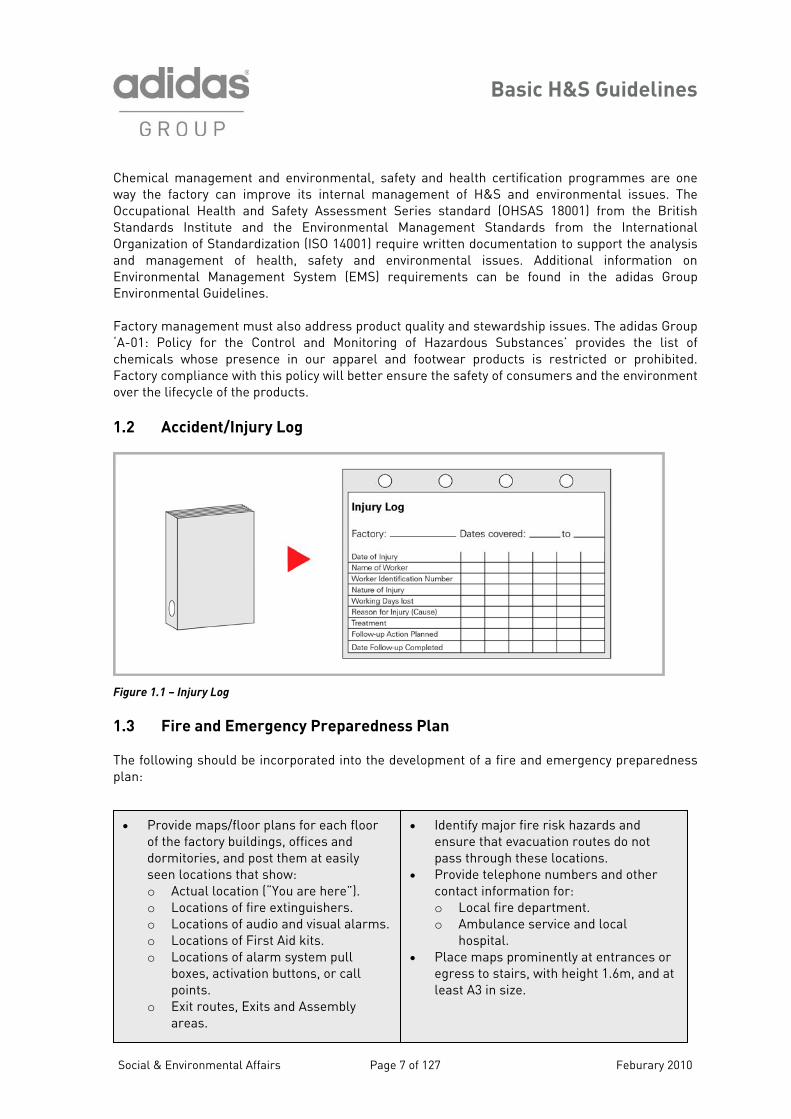
Factory management must also address product quality and stewardship issues. The adidas Group ‘A-01: Policy for the Control and Monitoring of Hazardous Substances’ provides the list of chemicals whose presence in our apparel and footwear products is restricted or prohibited. Factory compliance with this policy will better ensure the safety of consumers and the environment over the lifecycle of the products. 1.2 Accident/Injury Log
Figure
F ss Pl
he f w the dev p ess plan:
1.1 – Injury Log
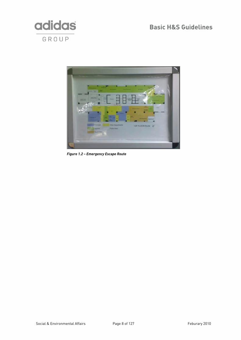
1.3 ire and Emergency Preparedne an T ollo ing should be incorporated into elo ment of a fire and emergency preparedn
• Provide maps/floor plans for each floor of the factory buildings, offices and dormitories, and post them at easily seen locations that show: o Actual location (“You are here”). o Locations of fire extinguishers. o Locations of audio and visual alarms. o Locations of First Aid kits. o Locations of alarm system pull
boxes, activation buttons, or call points.
o Exit routes, Exits and Assembly areas.
• Identify major fire risk hazards and ensure that evacuation routes do not pass through these locations.
• Provide telephone numbers and other contact information for: o Local fire department. o Ambulance service and local
hospital. • Place maps prominently at entrances or
egress to stairs, with height 1.6m, and at least A3 in size.
Social & Environmental Affairs Page 7 of 127 Feburary 2010
Basic H&S Guidelines
Figure 1.2 – Emergency Escape Route
Social & Environmental Affairs Page 8 of 127 Feburary 2010
Basic H&S Guidelines
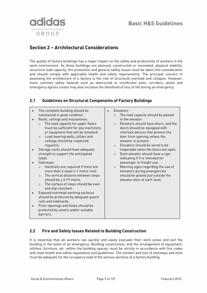
Section 2 – Architectural Considerations The quality of factory buildings has a major impact on the safety and productivity of workers in the work environment. As these buildings are planned, constructed or renovated, physical stability, structural load capacity, fire prevention and general safety issues must be taken into consideration and should comply with applicable health and safety requirements. The principal concern in assessing the architecture of a factory is the risk of structural overload and collapse. However, more common safety hazards such as obstructed or insufficient exits, corridors, aisles and emergency egress routes may also increase the likelihood of loss of life during an emergency. 2.1 Guidelines on Structural Components of Factory Buildings
• Elevators o The load capacity should be posted
in the elevator. o Elevators should have doors, and the
doors should be equipped with interlock devices that prevent the door from opening unless the elevator is present.
o Elevators should be wired to be inoperable when the doors are open.
o Each elevator should have a sign indicating if it is intended for passenger or freight use.
o Warning signs regarding the use of elevators during emergencies should be posted just outside the elevator door at each level.
• The complete building should be maintained in good condition.
• Roofs, ceilings and mezzanines: o The load capacity for upper floors
must be sufficient for any machinery or equipment that will be installed.
o Load-bearing walls, pillars and ceilings should be inspected regularly.
• Storage racks should have adequate strength to support the anticipated loads.
• Stairways: o Handrails are required if there are
more than 4 steps (>1 metre rise). o The vertical distance between steps
should be < 0.19 metre. o The surface of steps should be even
and slip-resistant. • Exposed overhead working surfaces
should be protected by adequate guard rails and toeboards.
• Floor openings and holes should be protected by covers and/or suitable barriers.
2.2 Fire and Safety Issues Related to Building Construction It is essential that all workers can quickly and easily evacuate their work areas and exit the building in the event of an emergency. Building construction, and the arrangement of equipment, utilities, furniture, etc. within the building spaces, must be strictly in accordance with fire codes and meet health and safety regulations and guidelines. The number and size of stairways and exits must be adequate for the occupancy load of the various sections of a factory building.
Social & Environmental Affairs Page 9 of 127 Feburary 2010
Basic H&S Guidelines
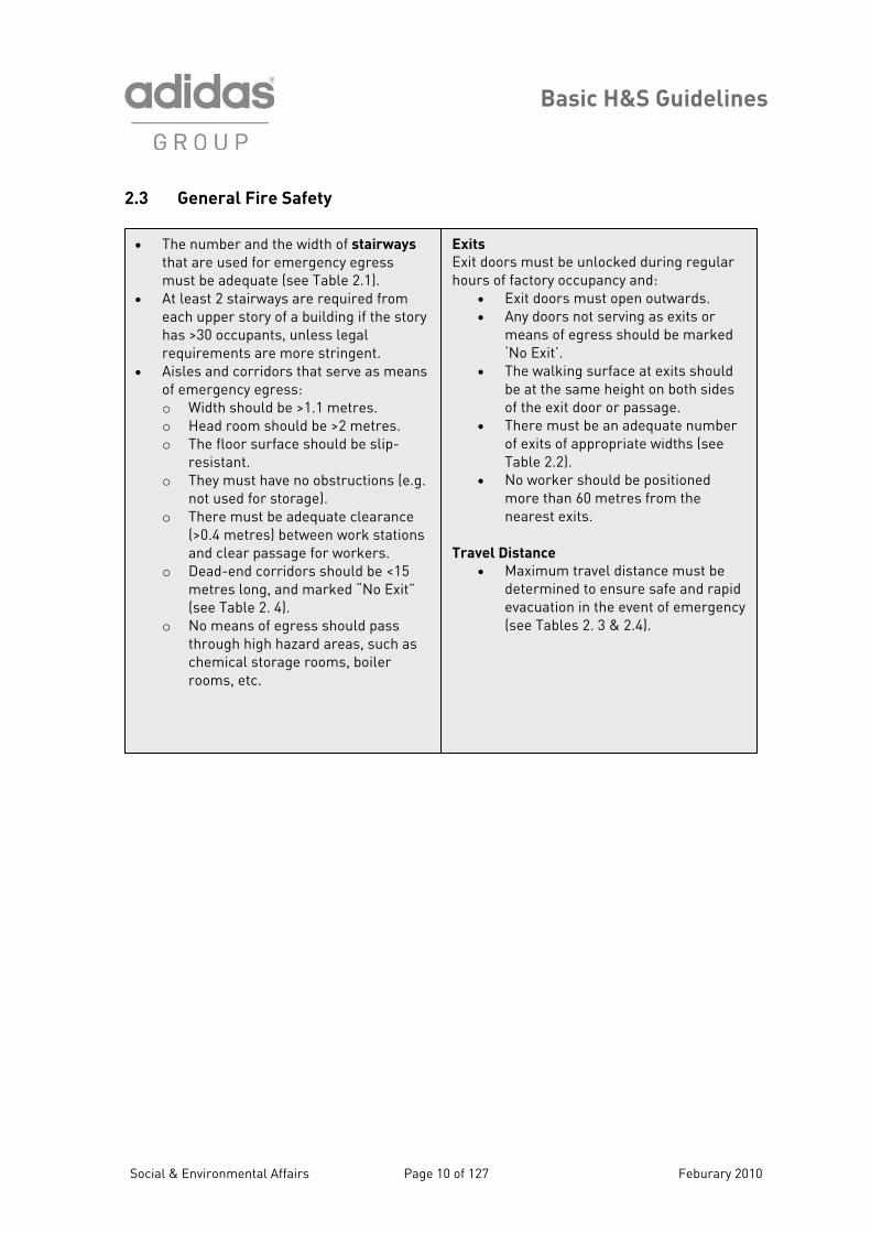
2.3 General Fire Safety
Exits Exit doors must be unlocked during regular hours of factory occupancy and:
• Exit doors must open outwards. • Any doors not serving as exits or
means of egress should be marked ‘No Exit’.
• The walking surface at exits should be at the same height on both sides of the exit door or passage.
• There must be an adequate number of exits of appropriate widths (see Table 2.2).
• No worker should be positioned more than 60 metres from the nearest exits.
Travel Distance
• Maximum travel distance must be determined to ensure safe and rapid evacuation in the event of emergency
(see Tables 2. 3 & 2.4).
• The number and the width of stairways that are used for emergency egress must be adequate (see Table 2.1).
• At least 2 stairways are required from each upper story of a building if the story has >30 occupants, unless legal requirements are more stringent.
• Aisles and corridors that serve as means of emergency egress: o Width should be >1.1 metres. o Head room should be >2 metres. o The floor surface should be slip-
resistant. o They must have no obstructions (e.g.
not used for storage). o There must be adequate clearance
(>0.4 metres) between work stations and clear passage for workers.
o Dead-end corridors should be <15 metres long, and marked “No Exit” (see Table 2. 4).
o No means of egress should pass through high hazard areas, such as chemical storage rooms, boiler rooms, etc.
Social & Environmental Affairs Page 10 of 127 Feburary 2010
Basic H&S Guidelines
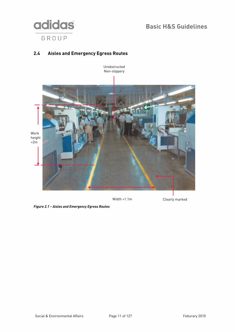
2.4 Aisles and Emergency Egress Routes
Figure 2.1 – Aisles and Emergency Egress Routes
Width >1.1m Clearly marked
Unobstructed Non-slippery
Work height >2m
Social & Environmental Affairs Page 11 of 127 Feburary 2010
Basic H&S Guidelines
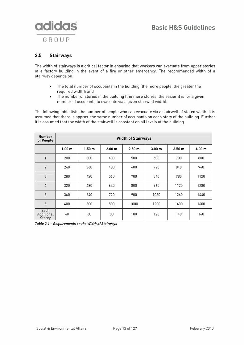
2.5 Stairways The width of stairways is a critical factor in ensuring that workers can evacuate from upper stories of a factory building in the event of a fire or other emergency. The recommended width of a stairway depends on:
• The total number of occupants in the building (the more people, the greater the required width); and
• The number of stories in the building (the more stories, the easier it is for a given number of occupants to evacuate via a given stairwell width).
The following table lists the number of people who can evacuate via a stairwell of stated width. It is assumed that there is approx. the same number of occupants on each story of the building. Further it is assumed that the width of the stairwell is constant on all levels of the building.
Number of People
Width of Stairways
1.00 m 1.50 m 2.00 m 2.50 m 3.00 m 3.50 m 4.00 m
1 200 300 400 500 600 700 800
2 240 360 480 600 720 840 960
3 280 420 560 700 840 980 1120
4 320 480 640 800 960 1120 1280
5 360 540 720 900 1080 1260 1440
6 400 600 800 1000 1200 1400 1600
Each Additional
Storey
40
60
80
100
120
140
160
Table 2.1 – Requirements on the Width of Stairways
Social & Environmental Affairs Page 12 of 127 Feburary 2010
Basic H&S Guidelines
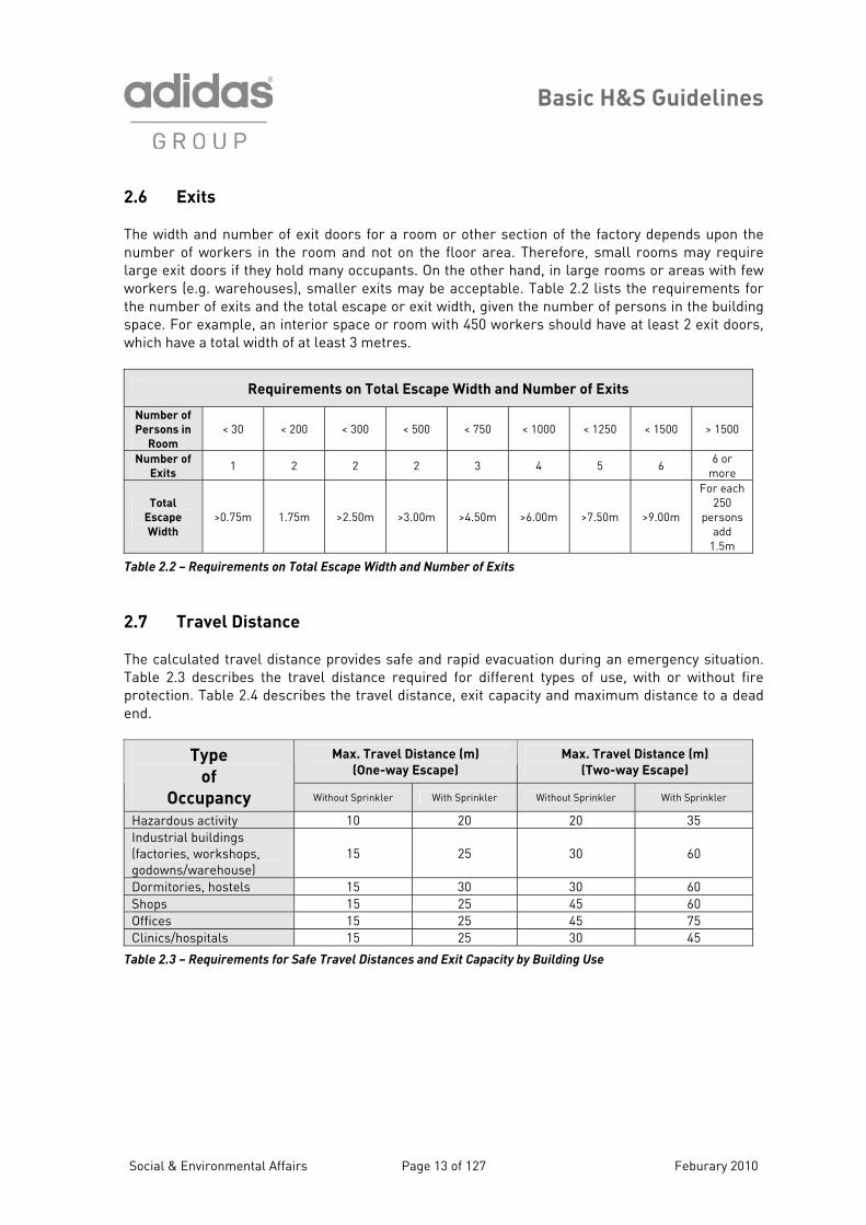
2.6 Exits The width and number of exit doors for a room or other section of the factory depends upon the number of workers in the room and not on the floor area. Therefore, small rooms may require large exit doors if they hold many occupants. On the other hand, in large rooms or areas with few workers (e.g. warehouses), smaller exits may be acceptable. Table 2.2 lists the requirements for the number of exits and the total escape or exit width, given the number of persons in the building space. For example, an interior space or room with 450 workers should have at least 2 exit doors, which have a total width of at least 3 metres.
Requirements on Total Escape Width and Number of Exits
Number of
Persons in
Room < 30 < 200 < 300 < 500 < 750 < 1000 < 1250 < 1500 > 1500
Number of
Exits 1 2 2 2 3 4 5 6 6 or
more
Total
Escape
Width >0.75m 1.75m >2.50m >3.00m >4.50m >6.00m >7.50m >9.00m
For each 250
persons add
1.5m
Table 2.2 – Requirements on Total Escape Width and Number of Exits
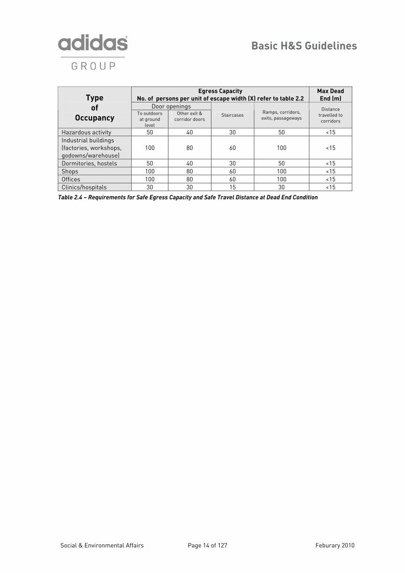
2.7 Travel Distance The calculated travel distance provides safe and rapid evacuation during an emergency situation. Table 2.3 describes the travel distance required for different types of use, with or without fire protection. Table 2.4 describes the travel distance, exit capacity and maximum distance to a dead end.
Max. Travel Distance (m)
(One-way Escape)
Max. Travel Distance (m)
(Two-way Escape) Type
of
Occupancy Without Sprinkler With Sprinkler Without Sprinkler With Sprinkler
Hazardous activity 10 20 20 35 Industrial buildings (factories, workshops, godowns/warehouse)
15 25 30 60
Dormitories, hostels 15 30 30 60 Shops 15 25 45 60 Offices 15 25 45 75 Clinics/hospitals 15 25 30 45
Table 2.3 – Requirements for Safe Travel Distances and Exit Capacity by Building Use
Social & Environmental Affairs Page 13 of 127 Feburary 2010
Basic H&S Guidelines
Egress Capacity
No. of persons per unit of escape width (X) refer to table 2.2
Max Dead
End (m)
Door openings Type
of
Occupancy To outdoors at ground
level
Other exit & corridor doors
Staircases Ramps, corridors, exits, passageways
Distance travelled to corridors
Hazardous activity 50 40 30 50 <15 Industrial buildings (factories, workshops, godowns/warehouse)
100 80 60 100 <15
Dormitories, hostels 50 40 30 50 <15 Shops 100 80 60 100 <15 Offices 100 80 60 100 <15 Clinics/hospitals 30 30 15 30 <15
Table 2.4 – Requirements for Safe Egress Capacity and Safe Travel Distance at Dead End Condition
Social & Environmental Affairs Page 14 of 127 Feburary 2010
Basic H&S Guidelines
Section 3 – Fire Safety Each year industrial fires cause injuries and loss of life and property. These losses can be avoided with the proper implementation of fire prevention measures and emergency preparedness. Fire extinguishers are one of the less expensive aspects of fire safety, but their use in factories is often compromised by poor maintenance, inappropriate and/or obstructed placement, and lack of worker training. Automatic sprinkler systems, when adequately designed, installed and maintained, are up to 95%+ effective and offer the best protection for building occupants and property. Every country has fire safety legislation and fire safety and building codes. Suppliers should understand and comply with these codes and regulations. General guidance on fire safety is given below and further details can be found in the adidas Group’s Fire Safety Guidance Note. Whenever there is a conflict between national codes and the adidas Group guidance, the most stringent
standard should apply. 3.1 Fire Safety Guidelines
• “No Smoking” signs should be displayed prominently throughout the premises.
• Fire hydrants and fire hoses should be inspected and tested at least twice yearly and have control tags as documentation.
• Automatic sprinkler system operation: o An independent water supply for the
sprinkler system is required. o Pressure checks of the water
storage container should be conducted every 5 years and documented.
o Water level and pressure, water pumps and the general condition of related equipment should be inspected monthly.
o Sprinkler heads should be kept clean.
o Water flow through the sprinkler system should activate the building fire alarm.
o Sprinkler piping should not be used to support unrelated equipment or materials.
o There should be at least 0.45 metre clearance between sprinkler heads and stored materials.
• Fire alarm systems (sound and light) should be installed which are distinct from other alarms and notification systems: o Full testing of alarm systems every
three months. o All records of tests, maintenance,
repair or replacement of alarm systems should be retained.
• Emergency lighting should be installed along egress routes, at exits, in stairwells, and at other appropriate locations (see Figure 3.5): o Lighting should be >1 lux. o Inspection and testing with
documentation every month. o Illuminated “EXIT” signs with back-
up power supply are required at exits and along egress routes.
• Sufficient directional and exit signs to ensure that all egress routes from all areas of the building to exits are clearly indicated.
• Exit signs should be clearly legible with pictogram and wording in English and the local language.
• Assembly areas outside the building should be designated, and should not interfere with emergency service.
Social & Environmental Affairs Page 15 of 127 Feburary 2010
Basic H&S Guidelines
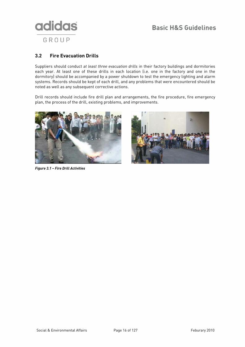
3.2 Fire Evacuation Drills Suppliers should conduct at least three evacuation drills in their factory buildings and dormitories each year. At least one of these drills in each location (i.e. one in the factory and one in the dormitory) should be accompanied by a power shutdown to test the emergency lighting and alarm systems. Records should be kept of each drill, and any problems that were encountered should be noted as well as any subsequent corrective actions. Drill records should include fire drill plan and arrangements, the fire procedure, fire emergency plan, the process of the drill, existing problems, and improvements. Figure 3.1 – Fire Drill Activities
Social & Environmental Affairs Page 16 of 127 Feburary 2010
Basic H&S Guidelines
3.3 Background Information on the Development and Propagation of Fires
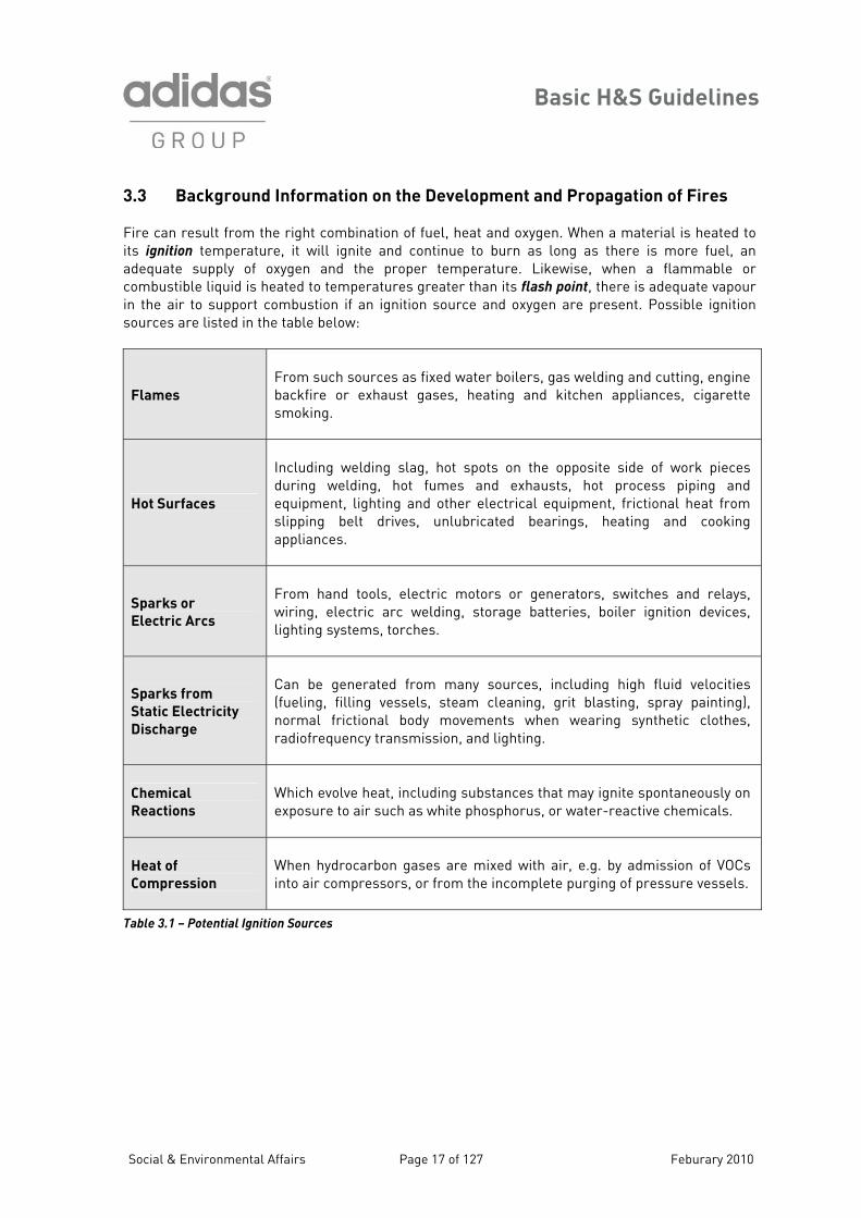
Fire can result from the right combination of fuel, heat and oxygen. When a material is heated to its ignition temperature, it will ignite and continue to burn as long as there is more fuel, an adequate supply of oxygen and the proper temperature. Likewise, when a flammable or combustible liquid is heated to temperatures greater than its flash point, there is adequate vapour in the air to support combustion if an ignition source and oxygen are present. Possible ignition sources are listed in the table below:
Flames
From such sources as fixed water boilers, gas welding and cutting, engine backfire or exhaust gases, heating and kitchen appliances, cigarette smoking.
Hot Surfaces
Including welding slag, hot spots on the opposite side of work pieces during welding, hot fumes and exhausts, hot process piping and equipment, lighting and other electrical equipment, frictional heat from slipping belt drives, unlubricated bearings, heating and cooking appliances.
Sparks or
Electric Arcs
From hand tools, electric motors or generators, switches and relays, wiring, electric arc welding, storage batteries, boiler ignition devices, lighting systems, torches.
Sparks from
Static Electricity
Discharge
Can be generated from many sources, including high fluid velocities (fueling, filling vessels, steam cleaning, grit blasting, spray painting), normal frictional body movements when wearing synthetic clothes, radiofrequency transmission, and lighting.
Chemical
Reactions
Which evolve heat, including substances that may ignite spontaneously on exposure to air such as white phosphorus, or water-reactive chemicals.
Heat of
Compression
When hydrocarbon gases are mixed with air, e.g. by admission of VOCs into air compressors, or from the incomplete purging of pressure vessels.
Table 3.1 – Potential Ignition Sources
Social & Environmental Affairs Page 17 of 127 Feburary 2010
Basic H&S Guidelines
Social & Environmental Affairs Page 18 of 127 Feburary 2010
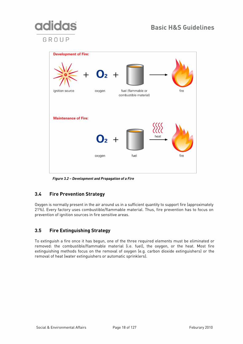
Figure 3.2 – Development and Propagation of a Fire
.4 Fire Prevention Strategy
around us in a sufficient quantity to support fire (approximately
extinguish a fire once it has begun, one of the three required elements must be eliminated or removed: the combustible/flammable material (i.e. fuel), the oxygen, or the heat. Most fire extinguishing methods focus on the removal of oxygen (e.g. carbon dioxide extinguishers) or the removal of heat (water extinguishers or automatic sprinklers).
3 Oxygen is normally present in the air21%). Every factory uses combustible/flammable material. Thus, fire prevention has to focus on prevention of ignition sources in fire sensitive areas.
.5 Fire Extinguishing Strategy 3 To
Basic H&S Guidelines
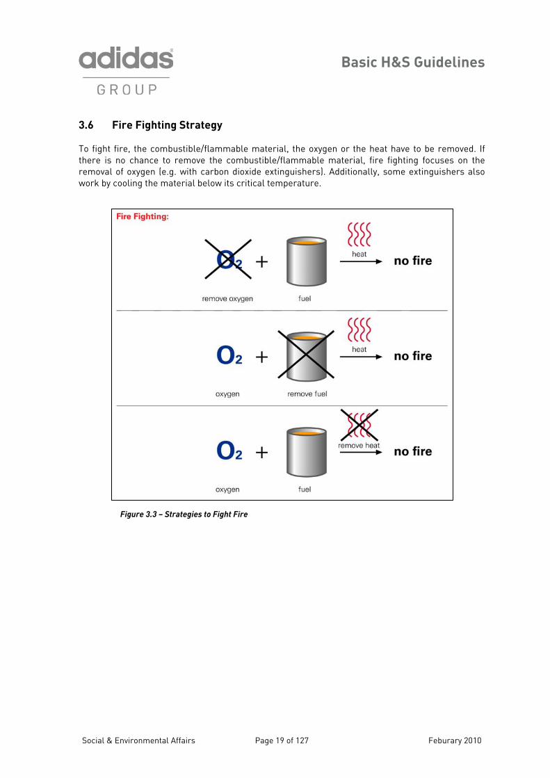
3.6 Fire Fighting Strategy To fight fire, the combustible/flammable material, the oxygen or the heat have to be removed. If there is no chance to remove the combustible/flammable material, fire fighting focuses on the removal of oxygen (e.g. with carbon dioxide extinguishers). Additionally, some extinguishers also work by cooling the material below its critical temperature.
Figure 3.3 – Strategies to Fight Fire
Social & Environmental Affairs Page 19 of 127 Feburary 2010
Basic H&S Guidelines
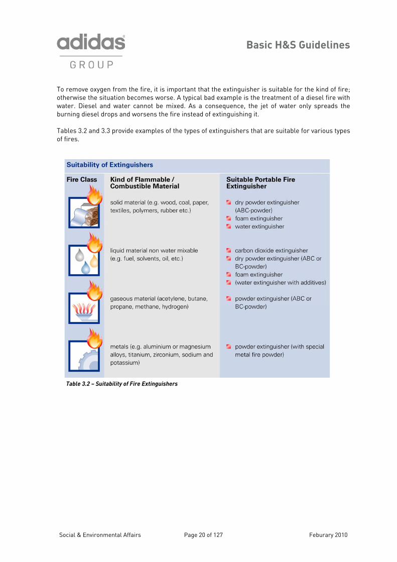
To remove oxygen from the fire, it is important that the extinguisher is suitable for the kind of fire; otherwise the situation becomes worse. A typical ad example is the treatment of a diesel fire with
s a consequence, the jet of water only spreads the urning diesel drops and worsens the fire instead of extinguishing it.
ables 3.2 and 3.3 provide examples of the types of extinguishers that are suitable for various types f fires.
bwater. Diesel and water cannot be mixed. Ab To
Table 3.2 – Suitability of Fire
Extinguishers
Social & Environmental Affairs Page 20 of 127 Feburary 2010
Basic H&S Guidelines
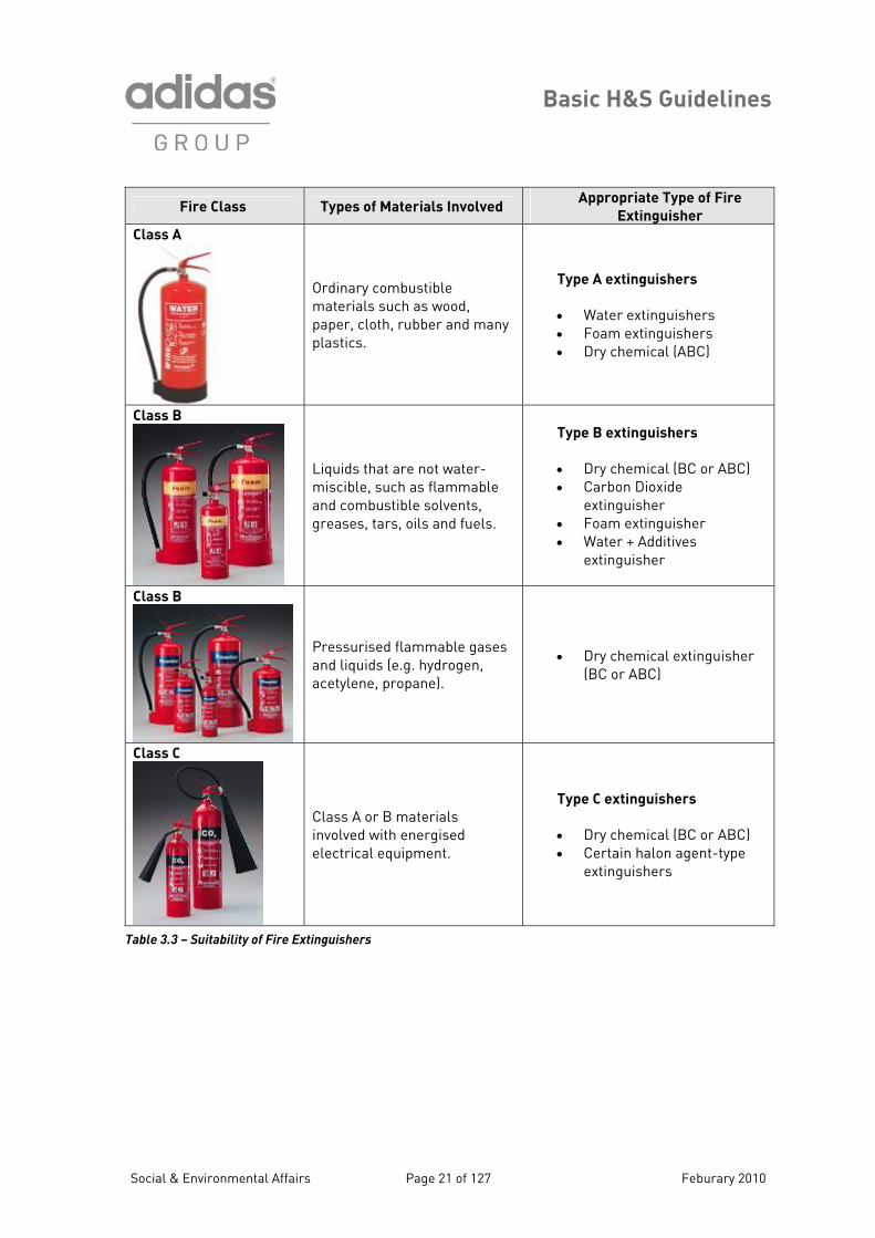
Fire Class Types of Materials Involved Appropriate Type of Fire
Extinguisher
Class A
Ordinary combustible materials such as wood, paper, cloth, rubber and many plastics.
Type A extinguishers
• Water extinguishers • Foam extinguishers • Dry chemical (ABC)
Class B
Liquids that are not water-miscible, such as flammable and combustible solvents,
Type B e
• Dry chemical (BC or ABC) • Carbon Dioxide
extinguisher • • Water + Additives
x
greases, tars, oils and fuels.
xtinguishers
Foam extinguisher
e tinguisher
Class B
Pressurised flammable gases • isher
Band liquids (e.g. hydrogen, acetylene, propane).
Dry chemical extingu( C or ABC)
Class C
Class A or B materials involved with energised electrical equipment.
• Dry chemical (BC or ABC) • Certain halon agent-type
extinguishers
Type C extinguishers
Table 3.3 – Suitability of Fire Extinguishers
Social & Environmental Affairs Page 21 of 127 Feburary 2010
Basic H&S Guidelines
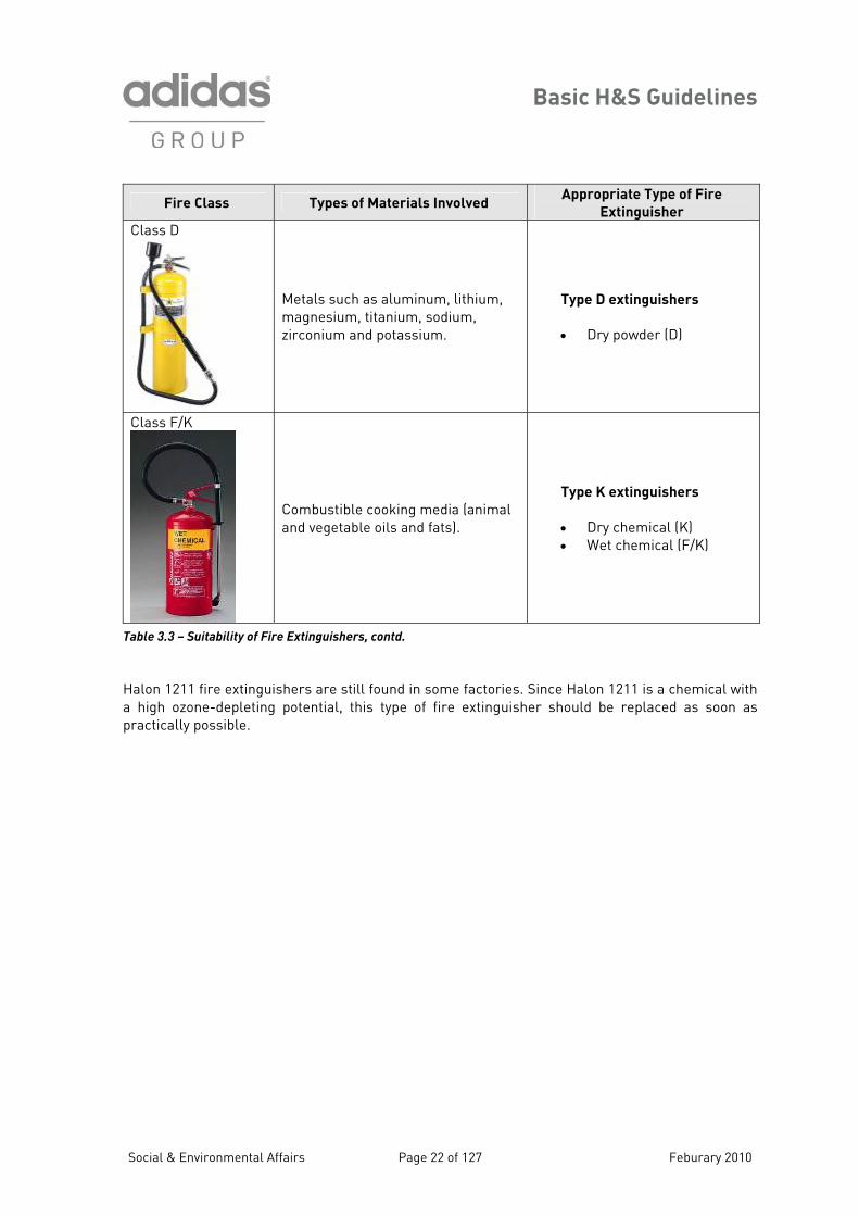
Fire Class Types of Materials Involved Appropriate Type of Fire
Extinguisher
Class D
Metals such as alummagnesium, titanium, zirconium and potassiu
inumso mm.
rs , lithium, diu ,
Type D extinguishe
• Dry powder (D)
Class F/K
Combustible cooking media (d fats).
)
animal Type K extinguishers
• Dry chemical (K) and vegetable oils an• Wet chemical (F/K
Tabl 3.3 – Suitability of Fire Extinguishers, contd.
1211 fire extinguishers are still found in
e
alon some factories. Since Halon 1211 is a chemical with high ozone-depleting potential, this type of fire extinguisher should be replaced as soon as ractically possible.
Hap
Social & Environmental Affairs Page 22 of 127 Feburary 2010
Basic H&S Guidelines
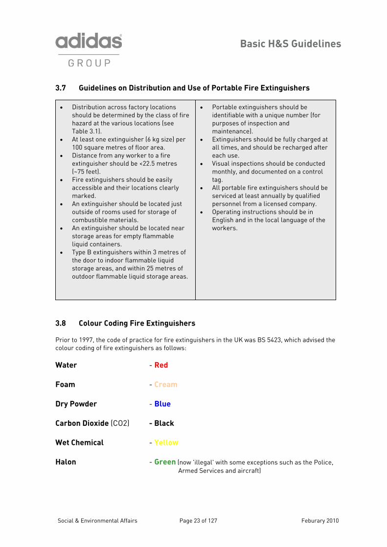
3.7 Guidelines on Distribution and Use of Portable Fire Extinguishers
23, which advised the olour coding of fire extinguishers as follows:
er
alon - Green (now 'illegal' with some exceptions such as the Police, Armed Services and aircraft)
• Distribution across factory locations should be determined by the class of fire hazard at the various locations (see Table 3.1).
• At least one extinguisher (6 kg size) per 100 square metres of floor area.
• Distance from any worker to a fire extinguisher should be <22.5 metres (~75 feet).
• Fire extinguishers should be easily accessible and their locations clearly marked.
• An extinguisher should be located just outside of rooms used for storage of combustible materials.
• An extinguisher should be located near storage areas for empty flammable liquid containers.
• Type B extinguishers within 3 metres of the door to indoor flammable liquid storage areas, and within 25 metres of outdoor flammable liquid storage areas.
• Portable extinguishers should be identifiable with a unique number (for purposes of inspection and maintenance).
• Extinguishers should be fully charged at all times, and should be recharged after each use.
• Visual inspections should be conducted monthly, and documented on a control tag.
• All portable fire extinguishers should be serviced at least annually by qualified personnel from a licensed company.
• Operating instructions should be in English and in the local language of the workers.
3.8 Colour Coding Fire Extinguishers Prior to 1997, the code of practice for fire extinguishers in the UK was BS 54c Wat - Red
Foam - Cream
Dry Powder - Blue
Carbon Dioxide (CO2) - Black
Wet Chemical - Yellow
H
Social & Environmental Affairs Page 23 of 127 Feburary 2010
Basic H&S Guidelines
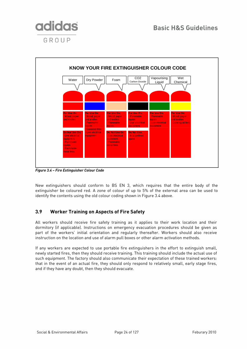
For Use On:· Wood, paper and textiles
For Use On:· Wood, paper and textiles· Flammable liquids
For Use On:· Wood, paper and textiles· Flammable liquids
For Use On:· Flammable liquids· Live electrical equipment
For Use On:· Flamm ble liquids· Live e trical equipm t
For Use On:· Wood, paper and textiles· Cooking oil fires
· Gaseous firesDo Not Use On:· Live electrical equipment· Flammable liquids· Flammable metal fires
· Live electrical equipment
Do Not Use On:· Live electrical equipment· Flammable metal fires
Do Not Use: · In a confined space
KNOW YOUR FIRE EXTINGUISHER COLOUR CODE
a
lecen
VapoLi
urising quid
Wet Chemical
CO2 Carbon DioxideFoamDry PowderWater
Figure 3.4 – Fire Extinguisher Colour Code
ew extinguishers should conform to BS EN 3, which requires that the entire body of the xtinguisher be coloured red. A zone of colour of up to 5% of the external area can be used to entify the contents using the old colour coding shown in Figure 3.4 above.
.9 Worker Training on Aspects of Fire Safety
ll workers should receive fire safety training as it applies to their work location and their ormitory (if applicable). Instructions on emergency evacuation procedures should be given as art of the workers’ initial orientation and regularly thereafter. Workers should also receive struction on the location and use of alarm pull boxes or other alarm activation methods.
any workers are expected to use portable fire extinguishers in the effort to extinguish small, ewly started fires, then they should receive training. This training should include the actual use of uch equipment. The factory should also communicate their expectation of these trained workers:
in the event of an actual fire, they should only respond to relatively small, early stage fires, nd if they have any doubt, then they should evacuate.
Neid 3
Adpin Ifnsthata
Social & Environmental Affairs Page 24 of 127 Feburary 2010
Basic H&S Guidelines
Social & Environmental Affairs Page 25 of 127 Feburary 2010
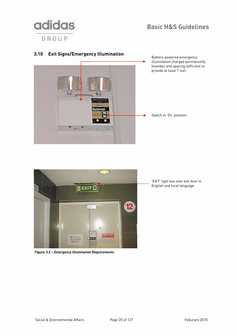
3.10 Exit Signs/Emergency Illumination
Figure 3.5 – Emergency Illumination Requirements
Battery-powered emergency illumination charged permanently (number and spacing sufficient to provide at least 1 lux) Switch in ‘On’ position
‘EXIT’ light box over exit door in English and local language
Basic H&S Guidelines
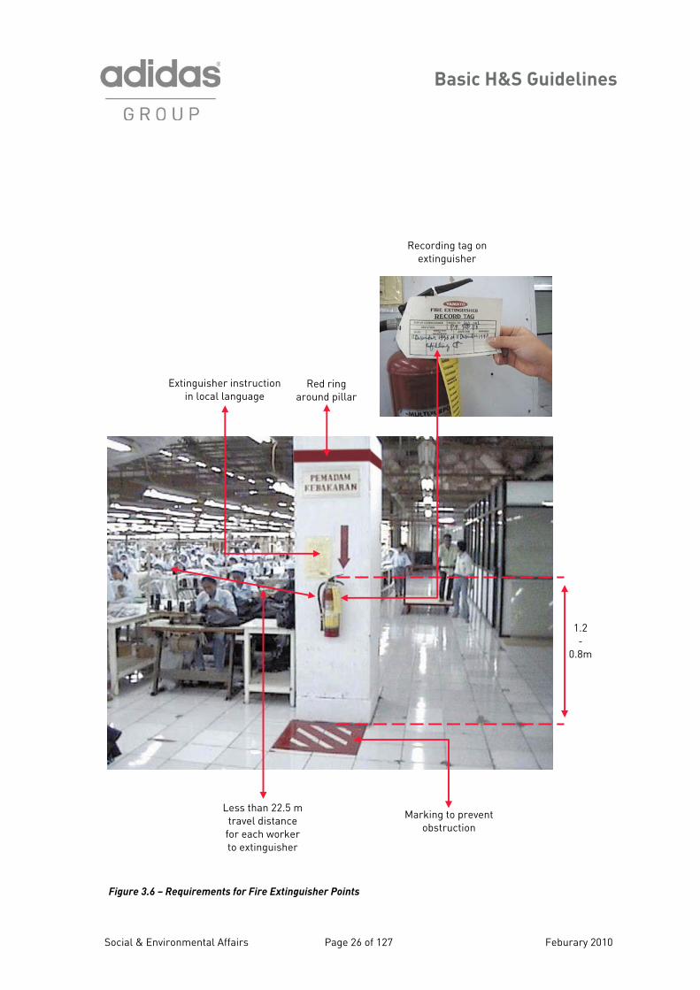
Extinguisher instruction in local language
Red ring around pillar
Less than 22.5 m travel distance
for each worker to extinguisher
Marking to prevent obstruction
Recording tag on extinguisher
1.2 -
0.8m
Figure 3.6 – Requirements for Fire Extinguisher PointsSocial & Environmental Affairs Page 26 of 127 Feburary 2010
Basic H&S Guidelines
Section 4 – First Aid It is one of the most important duties of factory management to provide immediate and appropriate first aid to employees who are injured on the company's premises. A well-organised first aid system ensures quick medical attention for employees and can prevent the loss of many working days. 4.1 Guidelines for First Aid
• First Aid providers should be adequately trained by professional personnel on an annual basis.
• The training should include a discussion of bloodborne pathogens.
First Aid kits should be available (see Figure 4.1) • A sufficient number of First Aid kits
should be available (1 kit for ~100 workers, and the nature of the work and the distribution of the workforce should be considered also).
• First Aid kits should be kept in sealed containers that provide protection from dirt and water.
• The kits should be unlocked, or the keys should be easily accessible at all times.
• The kits should have sufficient first aid materials, all within their expiration dates.
• The kits should be inspected monthly and restocked after each use or as required over time.
• The kits should contain first aid instructions in both English and the local language.
• The kits should include a means of identifying current First Aid providers (either a list of names and/or photographs).
A First Aid room should be available in
factories with more than 1,000 workers.
• Clearly identified by signs (see Section 8 of these Guidelines).
• Clean and in an easily accessible location for workers.
• The First Aid room should be used only for that purpose.
• Adequately equipped for the type of injuries that may reasonably be expected in the factory.
• First aid supplies are available and within their expiration dates.
• At least one bed in the First Aid room per 1,000 workers at the factory.
• Screens/curtains available to provide appropriate privacy.
• First Aid instructions are available in both English and the local language.
• Contact information and a means to contact medical personnel and a hospital are available (e.g. a phone).
• A doctor or qualified medical personnel should be available to provide emergency medical services during working hours.
• Have a written procedure for worker access to such on-site medical services at times other than in an emergency.
• All medicines should be kept locked in the First Aid room and accessed by the doctor or qualified medical personnel only.
First Aid Personnel should be identified and
trained
• One first aid provider should be appointed for every 100 workers.
Note: Consult your local SEA representative for additional guidance.
Social & Environmental Affairs Page 27 of 127 Feburary 2010
Basic H&S Guidelines
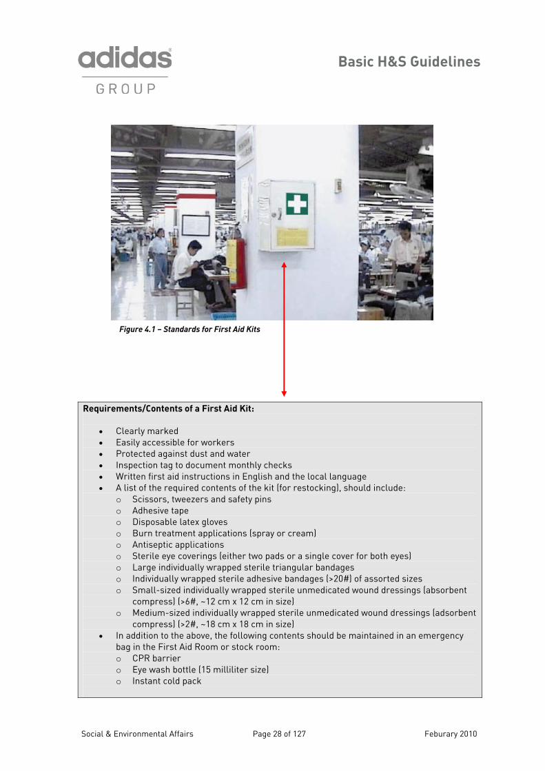
Figure 4.1 – Standards for First Aid Kits
Requirements/Contents of a First Aid Kit:
• Clearly marked • Easily accessible for workers • Protected against dust and water • Inspection tag to document monthly checks • Written first aid instructions in English and the local language • A list of the required contents of the kit (for restocking), should include:
o Scissors, tweezers and safety pins o Adhesive tape o Disposable latex gloves o Burn treatment applications (spray or cream) o Antiseptic applications o Sterile eye coverings (either two pads or a single cover for both eyes) o Large individually wrapped sterile triangular bandages o Individually wrapped sterile adhesive bandages (>20#) of assorted sizes o Small-sized individually wrapped sterile unmedicated wound dressings (absorbent
compress) (>6#, ~12 cm x 12 cm in size) o Medium-sized individually wrapped sterile unmedicated wound dressings (adsorbent
compress) (>2#, ~18 cm x 18 cm in size) • In addition to the above, the following contents should be maintained in an emergency
bag in the First Aid Room or stock room: o CPR barrier o Eye wash bottle (15 milliliter size) o Instant cold pack
Social & Environmental Affairs Page 28 of 127 Feburary 2010
Basic H&S Guidelines
Section 5 – Chemical Safety Management
5.1 Information on the Hazards Associated with Chemical Materials
Virtually all of the chemical materials that are used in production by factories are associated with one or more health or physical hazards. These hazards present potential adverse impacts on the workers, the work environment, the general public and the environment beyond the factory. The Environmental Guidelines outline further information on the environmental impacts due to chemical use, storage and disposal. 5.1.1 Health Hazards
A variety of health hazards are associated with chemicals in factories. The risk posed by any particular material is a function of:
• Severity of the Hazard – that is, the inherent toxicity of the chemical, or its “power” to cause adverse health effects.
• Exposure – the likelihood, duration and intensity of exposure (inhalation, dermal, ingestion) to the various forms of the chemical (gas or vapour, liquid, airborne dust or solid powders, etc.).
• Individual susceptibility or sensitisation – generally, there may be a range of individual susceptibilities to exposure to the various chemical agents. In addition, some individuals may become sensitised to certain chemicals after past exposures, and thereafter will exhibit adverse health effects at exposure levels that do not affect the majority of individuals.
The particular health hazards associated with different chemicals may vary. In general, there are two categories of adverse health effects: acute (those occurring during or soon after exposure) and chronic (those occurring after a long period of regular exposure, e.g. months or years). Within these two categories, chemicals may impact humans in a variety of ways:
• Carcinogenicity – exposure to some chemicals can lead to the development of cancer in one or more organs or body systems.
• Corrosivity – exposure can cause acute burns, ulceration and tissue damage in the eyes, skin and respiratory tract.
• Irritation – exposure can lead to skin, eye and respiratory irritation and dermatitis (but which is generally reversible).
• Target Organ Toxicity – some chemicals exhibit their toxicity at a specific organ (or “target”) such as the liver, kidneys, lungs, blood, eyes, ears, or the nervous system, including the reproductive system and the developing fetus.
• Sensitisation – exposure can lead to allergic reactions of the skin or the respiratory system (usually mediated by the immune system).
It is not feasible to eliminate all risk from activities involving chemical materials, but risk can be managed to an acceptable minimum. For inhalation exposure to chemicals, this level of minimum acceptable risk is defined by occupational exposure limits such as the Threshold Limit Values (see Section 7).
Social & Environmental Affairs Page 29 of 127 Feburary 2010
Basic H&S Guidelines
5.1.2 Physical Hazards
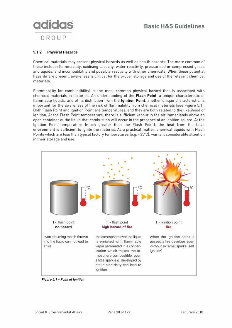
Chemical materials may present physical hazards as well as health hazards. The more common of these include: flammability, oxidising capacity, water reactivity, pressurised or compressed gases and liquids, and incompatibility and possible reactivity with other chemicals. When these potential hazards are present, awareness is critical for the proper storage and use of the relevant chemical materials. Flammability (or combustibility) is the most common physical hazard that is associated with chemical materials in factories. An understanding of the Flash Point, a unique characteristic of flammable liquids, and of its distinction from the Ignition Point, another unique characteristic, is important for the awareness of the risk of flammability from chemical materials (see Figure 5.1). Both Flash Point and Ignition Point are temperatures, and they are both related to the likelihood of ignition. At the Flash Point temperature, there is sufficient vapour in the air immediately above an open container of the liquid that combustion will occur in the presence of an ignition source. At the Ignition Point temperature (much greater than the Flash Point), the heat from the local environment is sufficient to ignite the material. As a practical matter, chemical liquids with Flash Points which are less than typical factory temperatures (e.g. <35oC), warrant considerable attention in their storage and use.
Figure 5.1 – Point of Ignition
Social & Environmental Affairs Page 30 of 127 Feburary 2010
Basic H&S Guidelines
5.2 a Sheets (MSDS) Man liers of chemicals are often q ers with in the absence of su ries should insist on the r SDS or equivalent written infor urchase.
he following categories of information should all be available on MSDSs:
Material Safety Dat
ufacturers and supp re uired by law to provide their custom MSDSs for their products. Even
eceipt of the Mch legal obligation, facto
mation for each chemical that they p
T
• Substance identification:
o Trade name o CAS # for each chemical ingredient o % of each ingredient
• Chemical data: o Molecular formula and weight
• Physical data: o Boiling point o Melting point o Solubility o Etc.
• Toxicity data • Occupational exposure limits • Chemical reactivity and incompatibilities • Fire and explosion data:
o Fire/explosion hazard o Flash point o Explosive limits o Ignition point/auto-ignition
temperature
• Fire extinguishing media • Health effects and First Aid measures
o Signs and symptoms of exposure o Effects of inhalation, ingestion, and eye
and skin contact o Antidotes or other treatments
• Safe handling, storage and disposal requirements
• Recommended spill and leak response procedures
• Protective equipment o Personal protective equipment to avoid
exposure o Protective measures for production
equipment or other factory installations
• Additional relevant information: o Contact information for the chemical
manufacturer/supplier o Date of the last MSDS revision
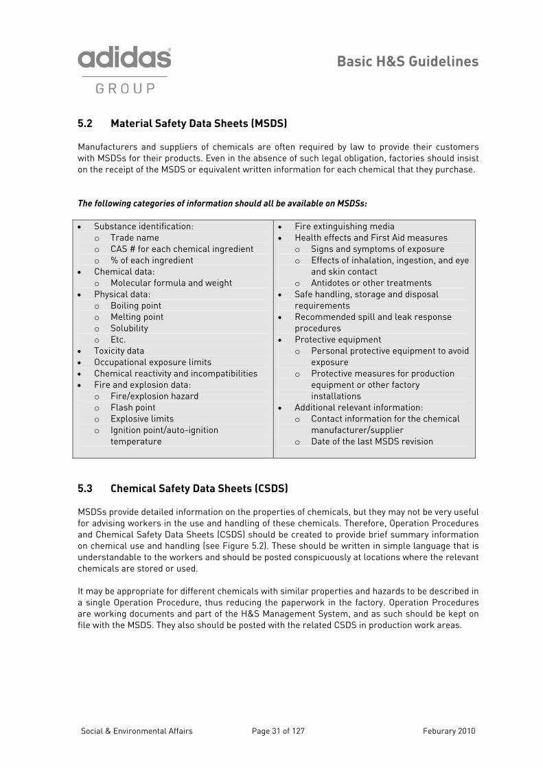
5.3 Chemical Safety Data Sheets (CSDS) MSDSs provide detailed information on the properties of chemicals, but they may not be very useful for advising workers in the use and handling of these chemicals. Therefore, Operation Procedures and Chemical Safety Data Sheets (CSDS) should be created to provide brief summary information on chemical use and handling (see Figure 5.2). These should be written in simple language that is understandable to the workers and should be posted conspicuously at locations where the relevant chemicals are stored or used. It may be appropriate for different chemicals with similar properties and hazards to be described in a single Operation Procedure, thus reducing the paperwork in the factory. Operation Procedures are working documents and part of the H&S Management System, and as such should be kept on file with the MSDS. They also should be posted with the related CSDS in production work areas.
Social & Environmental Affairs Page 31 of 127 Feburary 2010
Basic H&S Guidelines
Figure 5.2 – A Sample CSD S
s
s de za inimise e r ur n e Figure
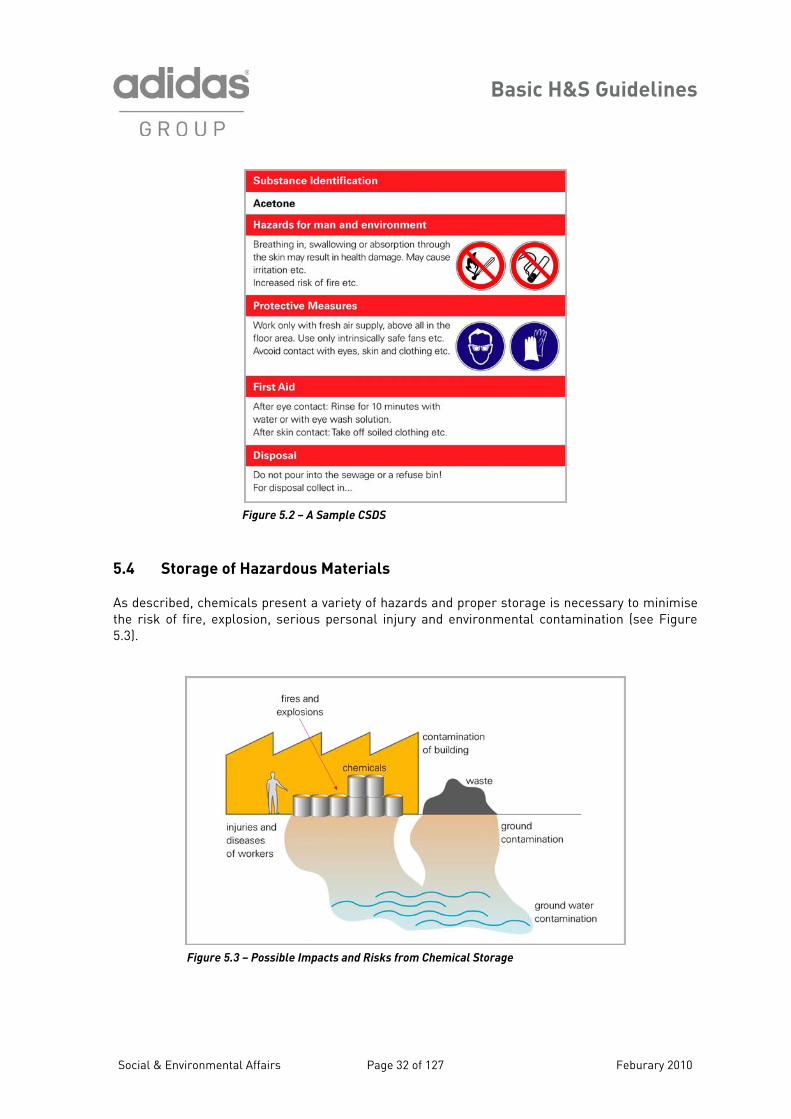
5.4 Storage of Hazardous Mat
scribed, chemicals present a variety of haisk of fire, explosion, serious personal inj
erial A rds and proper storage is necessary to m
y a d environmental contamination (seth5.3).
emical Storage – Possible Impacts and Risks from Ch Figure 5.3
Social & Environmental Affairs Page 32 of 27 Feburary 20 1 10
Basic H&S Guidelines
The MSDS for each chemical at the factory should include basic information and instructions elated to the proper storage of that material. If the MSDS is inadequate, then additional resources hould be consulted.
s a general rule, only a single day’s supply of a chemical should be present and available for use n production floors. Otherwise, all hazardous chemicals should be stored in designated locations
are segregated from production areas, office areas, dormitories, kitchens, etc. The following ble provides recommendations for such chemical storage areas.
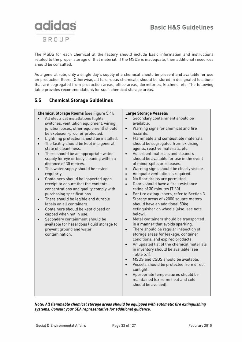
Note: All flammable chemical storage areas should be equipped with automatic fire extinguishing
systems. Consult your SEA representative for additional guidance.
rs Aothatta 5.5 Chemical Storage Guidelines
Chemical Storage Rooms (see Figure 5.4): • All electrical installations (lights,
switches, ventilation equipment, wiring, junction boxes, other equipment) should be explosion-proof or protected.
• Lightning protection should be installed. • The facility should be kept in a general
state of cleanliness. • There should be an appropriate water
supply for eye or body cleaning within a distance of 30 metres.
• This water supply should be tested regularly.
• Containers should be inspected upon receipt to ensure that the contents, concentrations and quality comply with purchasing specifications.
• There should be legible and durable labels on all containers.
• Containers should be kept closed or capped when not in use.
• Secondary containment should be available for hazardous liquid storage to prevent ground and water contamination.
Large Storage Vessels:
• Secondary containment should be available.
• Warning signs for chemical and fire hazards.
• Flammable and combustible materials should be segregated from oxidising agents, reactive materials, etc.
• Adsorbent materials and cleaners should be available for use in the event of minor spills or releases.
• Warning signs should be clearly visible. • Adequate ventilation is required. • No floor drains are permitted. • Doors should have a fire-resistance
rating of 30 minutes (T 30). • For fire extinguishers, refer to Section 3.
Storage areas of >2000 square meters should have an additional 50kg extinguisher on wheels (also: see note below).
• Metal containers should be transported in a manner that avoids sparking.
• There should be regular inspection of storage areas for leakage, container conditions, and expired products.
• An updated list of the chemical materials in inventory should be available (see Table 5.1).
• MSDS and CSDS should be available. • Vessels should be protected from direct
sunlight. • Appropriate temperatures should be
maintained (extreme heat and cold should be avoided).
Social & Environmental Affairs Page 33 of 127 Feburary 2010
Basic H&S Guidelines
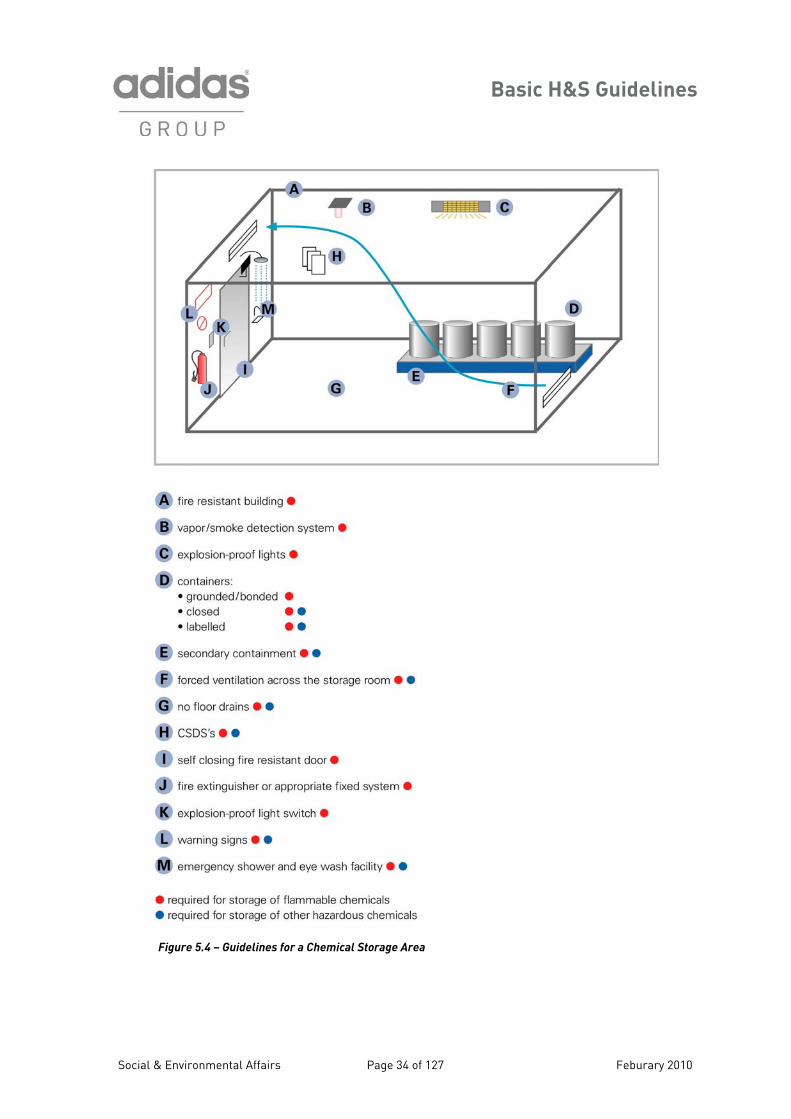
Figure 5.4 – Guidelines for a Chemical Storage Area
Social & Environmental Affairs Page 34 of 127 Feburary 2010
Basic H&S Guidelines
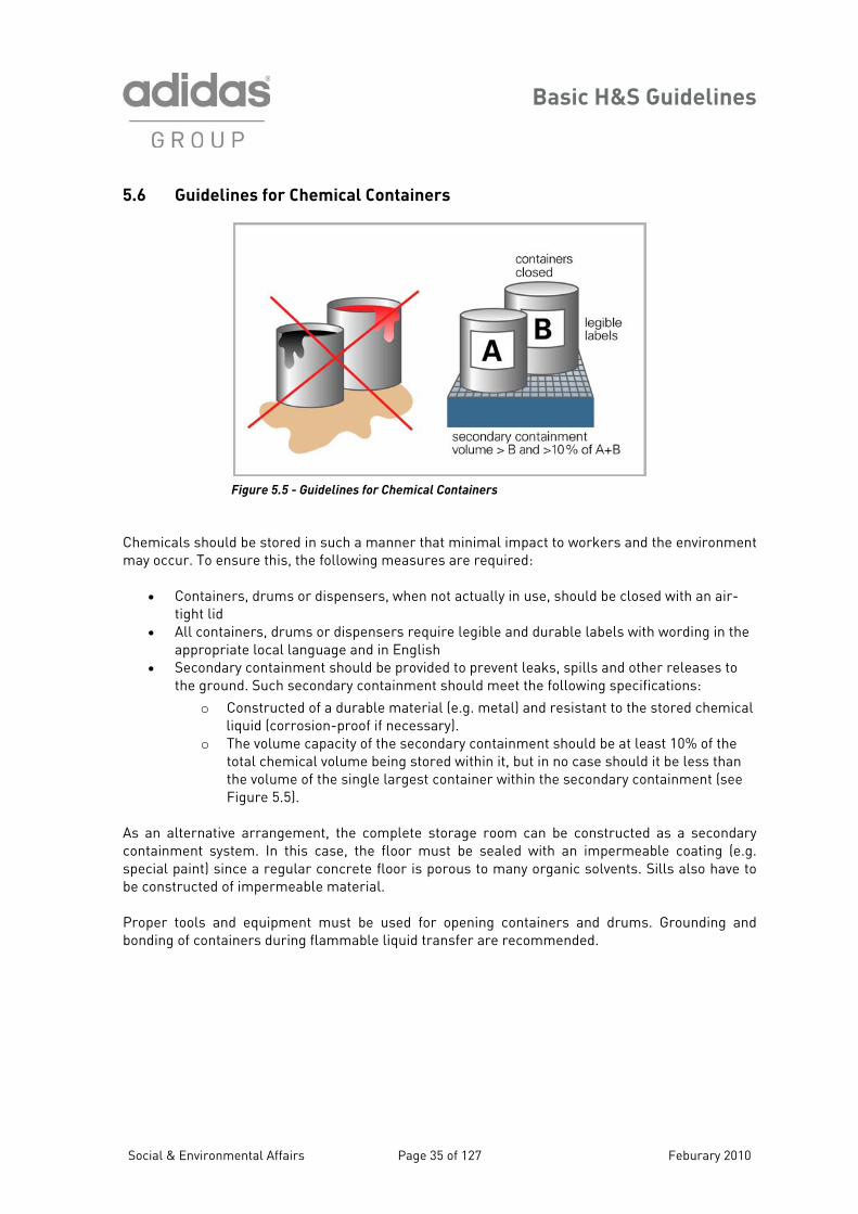
5.6 Guidelines for Chemical Containers
Figure 5.5 - Guidelines for Chemical Conta iners
Chemicals shou t may occur. To e e following measures are required:
English • Secondary containment should be provided to prevent leaks, spills and other releases to
stored chemical liquid (corrosion-proof if necessary).
o The volume capacity of the secondary containment should be at least 10% of the total chemical volume being stored within it, but in no case should it be less than the volume of the single largest container within the secondary containment (see Figure 5.5).
s an alternative arrangement, the complete storage room can be constructed as a secondary ontainment system. In this case, the floor must be sealed with an impermeable coating (e.g. pecial paint) since a regular concrete floor is porous to many organic solvents. Sills also have to
rial.
ld be stored in such a manner that minimal impact to workers and the environmennsure this, th
• Containers, drums or dispensers, when not actually in use, should be closed with an air-
tight lid • All containers, drums or dispensers require legible and durable labels with wording in the
appropriate local language and in
the ground. Such secondary containment should meet the following specifications:
o Constructed of a durable material (e.g. metal) and resistant to the
Acsbe constructed of impermeable mate Proper tools and equipment must be used for opening containers and drums. Grounding and bonding of containers during flammable liquid transfer are recommended.
Social & Environmental Affairs Page 35 of 127 Feburary 2010
Basic H&S Guidelines
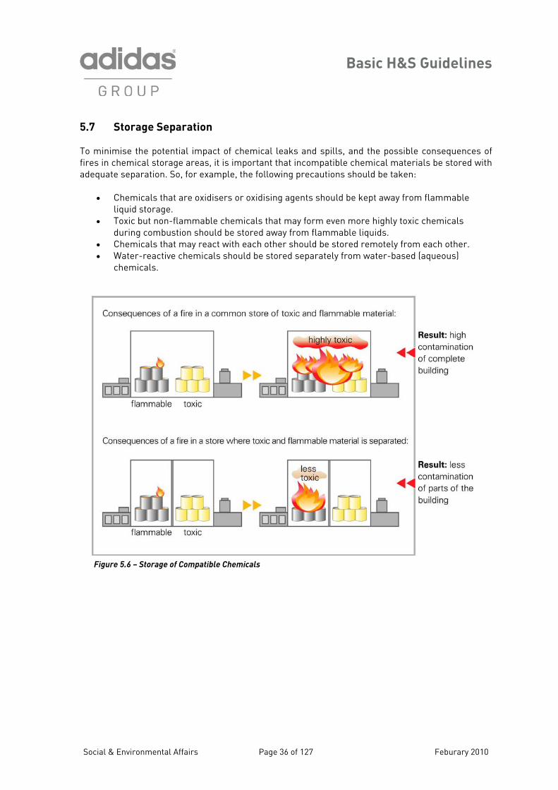
5.7 Storage Separation
To minimise the potential impact of chemical leaks and spills, and the possible consequences of fires in chemical storage areas, it is important that incompatible chemical materials be stored with adequate separation. So, for example, the following precautions should be taken: �
• Chemicals that are oxidisers or oxidising agents should be kept away from flammable liquid storage.
• Toxic but non-flammable chemicals that may form even more highly toxic chemicals during combustion should be stored away from flammable liquids.
• Chemicals that may react with each other should be stored remotely from each other. • Water-reactive chemicals should be stored separately from water-based (aqueous)
chemicals.
Figure 5.6 – Storage of Compatible Chemicals
Social & Environmental Affairs Page 36 of 127 Feburary 2010
Basic H&S Guidelines
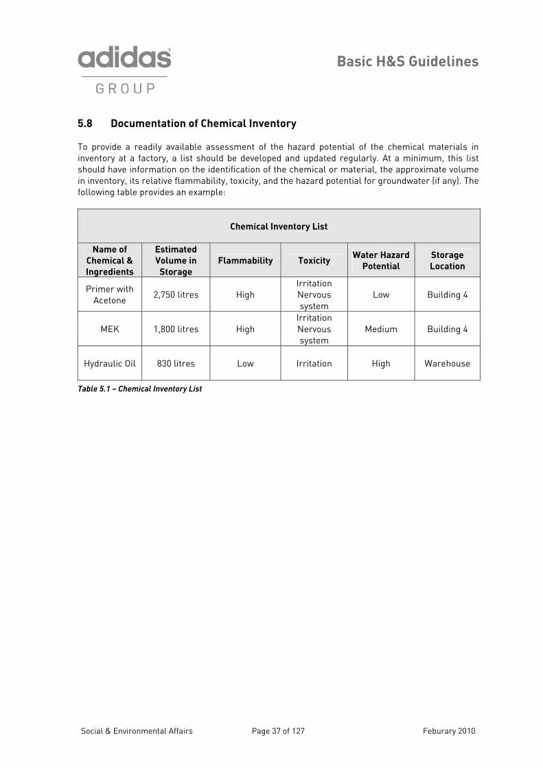
5 en Chemical Inventory To ead assess of the ha ntial of emical in inventory at a factory, a list should be developed and egularly. At a minimum, this list should have information n the identifica on of the c material, e approximate olume in inv bility, toxicity, and the tential dwate e following table provides an example:
.8 Docum tation of
provide a r ily available ment zard pote updated r
the ch materials
o ti hemical or th ventory, its relative flamma hazard po for groun r (if any). Th
Chemical Inventory List
Name of
Chemical &
Ingredients
Estimated
Volume in
Storage
Flammability Toxicity Water Hazard
Potential
Storage
Location
Primer with Acetone
2,750 litres
High
Irritation Nervous system
Low
Building 4
MEK
1,800 litres
High
Irritation Nervous system
Medium
Building 4
Hydraulic Oil
830 litres
Low
Irritation
High
Warehouse
Table 5.1 – Chemical Inventory List
Social & Environmental Affairs Page 37 of 127 Feburary 2010
Basic H&S Guidelines
Section 6 – Use of Hazardous Materials in Production
Workers in production areas must recognise that the chemicals and other materials that they use be ha ty and to the environment. If ers materials, and of the proper
recautions and other measures that can be taken to avoid these risks, then they will be more y se n ng
azar oup Environment on t.
o in ia a us e se haza hat worker exposure to
ese to an acceptable level, the o
.1 e in Prod c
can zardous to their health and present other risks to their safework have a basic understanding of the potential hazards of plikel to utilise them. While this document focu
dous chemicals, the adidas Grs o the impacts to workers as a result of usi
al Guidelines provide further informationhthe potential impacts to the natural environmen
crease worker awareness of the potent
T l h zards that are associated with hazardords, and to ensure tmat rials that they are using, to minimise the
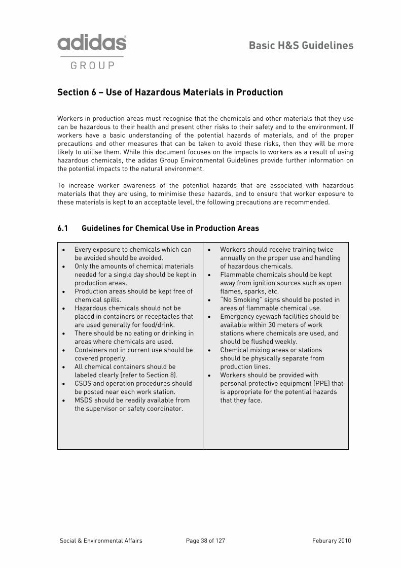
materials is keptth foll wing precautions are recommended. 6 Guidelines for Chemical Us u tion Areas
• ining twannually on the proper use and hanof hazardous chemicals. Flammable chemic
Workers should receive tra ice dling
ept
• able chemical use.
• Emergency eyewash facilities should be available within 30 meters of work stations where chemicals are used, and should be flushed weekly.
• Chemical mixing areas or stations should be physically separate from production lines.
• Workers should be provided with personal protective equipment (PPE) that is appropriate for the potential hazards that they face.
• als should be kaway from ignition sources such as open flames, sparks, etc. “No Smoking” signs should be posted inareas of flamm
• can be avoided should be avoided. Only the amounts of c
Every exposure to chemicals which
• hemical materials needed for a single day should be kproduction areas.
ept in
at are used generally for food/drink.
• There should be no eating or drinking in areas where chemicals are used.
• Containers not in current use should be covered properly.
• All chemical containers should be labeled clearly (refer to Section 8).
• CSDS and operation procedures should be posted near each work station.
• MSDS should be readily available from the supervisor or safety coordinator.
• Production areas should be kept free of chemical spills.
• Hazardous chemicals should not be placed in containers or receptacles th
Social & Environmental Affairs Page 38 of 127 Feburary 2010
Basic H&S Guidelines
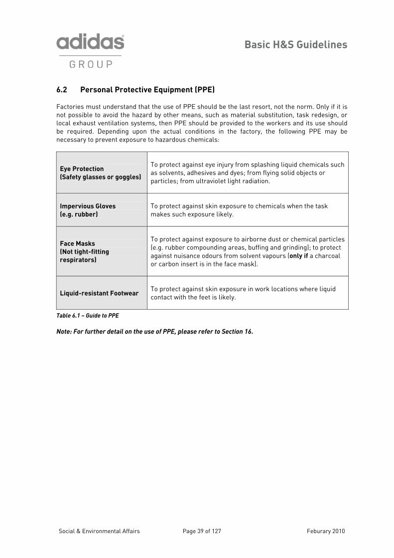
6.2 Personal Protective Factories must understand that he use of PPE should be the last resort, not the norm. Only if it is n the hazar n, or l entilation system ed to the workers and its use should be required. Depending upon the actual conditions in the factory, the following PPE may be necessary to prevent exposure t hazardous chemicals:
Equipment (PPE)
tot possible to avoid d by other means, such as material substitution, task redesig
s, then PPE should be providocal exhaust v
o
Eye Protection
(Safety glasses or goggles)
flying solid objects or
articles; from ultraviolet light radiation.
To protect against eye injury from splashing liquid chemicals suchas solvents, adhesives and dyes; fromp
Impervious Gloves
(e.g. rubber)
re to chemicals when the task akes such exposure likely.
To protect against skin exposum
Face Masks
(Not tight-fitting
respirators)
rne dust or chemical particles
(e.g. rubber compounding areas, buffing and grinding); to protect against nuisance odours from solvent vapours (only if a charcoal or carbon insert is in the face mask).
To protect against exposure to airbo
Liquid-resistant Footwear
To protect against skin exposure in work locations where liquid contact with the feet is likely.
Table 6.1 – Guide to PPE
ote: For further detail on the use of PPE, please refer to Section 16.
N
Social & Environmental Affairs Page 39 of 127 Feburary 2010
Basic H&S Guidelines
Section 7 – Worker Exposure to Hazardous Chemicals 7.1 Background Information Chemicals can be categorised generally as one of two types:
• Organic chemicals: molecules that are based on chains of carbon atoms mical compounds that do not contain carbon chains in their
and their related compounds, e.g. salts)
mount of organic chemicals in the air to which workers may be xposed, but it gives little information about the relative toxicity of the mixture.
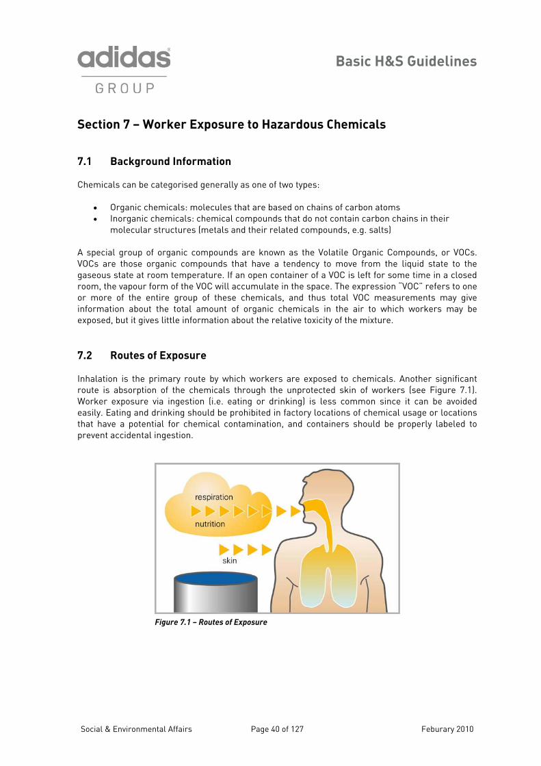
halation is the primary route by which workers are exposed to chemicals. Another significant oute is absorption of the chemicals through the unprotected skin of workers (see Figure 7.1). orker exposure via ingestion (i.e. eating or drinking) is less common since it can be avoided
asily. Eating and drinking should be prohibited in factory locations of chemical usage or locations at have a potential for chemical contamination, and containers should be properly labeled to
ent
• Inorganic chemicals: chemolecular structures (metals
A special group of organic compounds are known as the Volatile Organic Compounds, or VOCs. VOCs are those organic compounds that have a tendency to move from the liquid state to the gaseous state at room temperature. If an open container of a VOC is left for some time in a closed room, the vapour form of the VOC will accumulate in the space. The expression “VOC” refers to one or more of the entire group of these chemicals, and thus total VOC measurements may give information about the total ae
7.2 Routes of Exposure InrWethprev accidental ingestion.
Figure 7.1 – Routes of Exposure
Social & Environmental Affairs Page 40 of 127 Feburary 2010
Basic H&S Guidelines
7.3 Occupational Exposure Limits for Chemicals in the Air Prolonged or excessive exposure or contact with most hazardous chemicals can lead to adverse
ealth symptoms, illness, disease, and, in extreme cases, death. Other hazardous chemicals can ave similar adverse health effects after only short, or acute, contact with the chemical. overnment agencies and professional organisations have established airborne exposure limits for range of chemicals. These limits are intended to define workplace conditions to which it is ought that virtually all workers may be exposed on a regular basis without developing adverse
ealth effects.
he Threshold Limit Values (TLVs), which are published annually by the American Conference of overnmental Industrial Hygienists (ACGIH), have been selected as the appropriate set of exposure mits for use in factories. The limits that are specified are minimum standards; they are not tended to supercede more stringent national or local standards that may exist.
he TLVs have been established on the basis of an 8-hour workday and a 40-hour work week. owever, factory workers often have work schedules that approach 10-12 hour workdays and 60-our work weeks. To account for the likelihood of longer work shifts, the TLVs are reduced roportionately as the workers’ hours of chemical exposure increase.
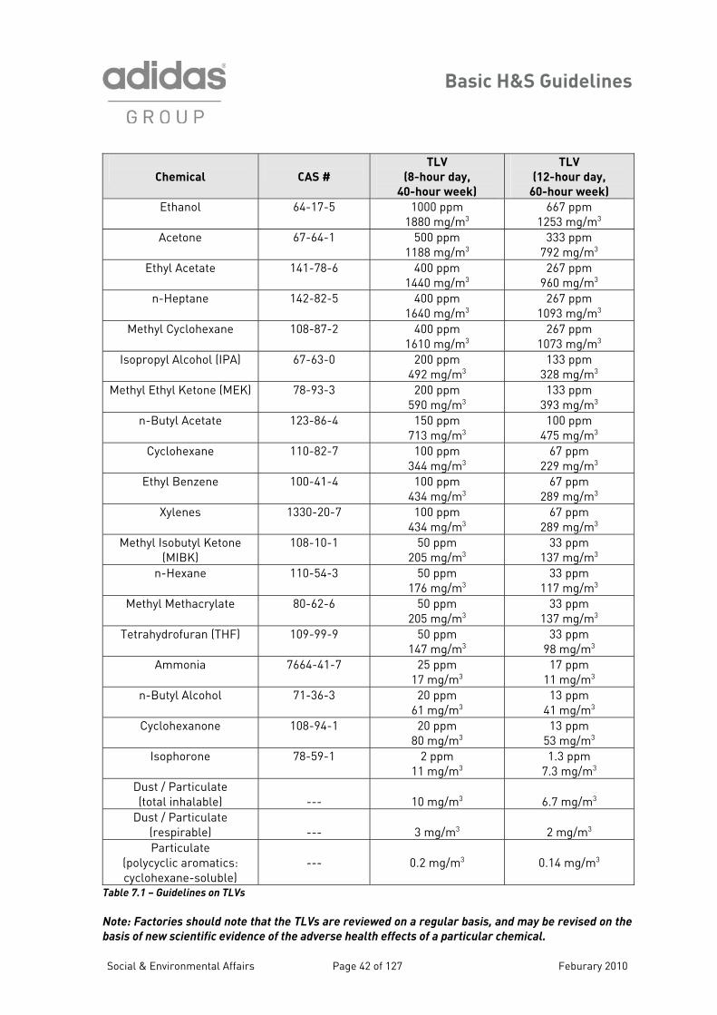
he following guidelines list the ACGIH’s 2006 TLVs for several chemicals that commonly are used footwear and apparel manufacturing. Workplace concentrations of these chemicals and dusts
hould be maintained below these exposure limits. The exposure limits are expressed in oncentration units of both “ppm” (parts per million in air) and “mg/m3” (milligrams per cubic etre of air).
hhGathh TGliin THhp Tinscm
Social & Environmental Affairs Page 41 of 127 Feburary 2010
Basic H&S Guidelines
Chemical
CAS #
TLV
( 8-hour day,
40-hour week)
TLV
( , 12-hour day
60-hour week)
Ethanol 64-17-5 1880 mg/m3 1253 mg/m3
1000 ppm 667 ppm
Acetone 67-64-1 1188 mg/m3 7
500 ppm 333 ppm 92 mg/m3
Ethyl Acetate 141-78-6 1440 mg/m3 9
400 ppm 267 ppm 60 mg/m3
n-Heptane 142-82-5 1640 mg/m3 1093 mg/m3
400 ppm 267 ppm
Methyl Cyclohexane 108-87-2 1610 mg/m3 1073 mg/m3
400 ppm 267 ppm
Isopropyl Alcohol (IPA) 67-63-0 4 3 3200 ppm 92 mg/m
133 ppm 28 mg/m3
Methyl Ethyl Ketone (MEK) 78-93-3 590 mg/m3 3
200 ppm 133 ppm 93 mg/m3
n-Butyl Acetate 123-86-4 713 mg/m3 475 mg/m3
150 ppm 100 ppm
Cyclohexane 110 -7 344 mg/m3 229 mg/m3
-82 100 ppm 67 ppm
Ethyl Benzene 100-41-4 434 mg/m3 289 mg/m3
100 ppm 67 ppm
Xylenes 133 -7 434 mg/m3 289 mg/m3
0-20 100 ppm 67 ppm
Methyl Isobutyl Ketone (MIBK)
108-10-1 50 ppm 205 mg/m3
33 ppm 137 mg/m3
n-Hexane 110-54-3 50 ppm 176 mg/m3
33 ppm 117 mg/m3
Me hyl Methacrylate 80-62-6 t 50 ppm 205 mg/m3
33 ppm 137 mg/m3
Tetrahydrofuran (THF) 109-99-9 50 ppm 147 mg/m3
33 ppm 98 mg/m3
Ammonia 7664-41-7 25 ppm 17 ppm 17 mg/m3 11 mg/m3
n-Butyl Alcohol 71-36-3 20 ppm 13 ppm 61 mg/m3 41 mg/m3
Cyclohexanone 108-94-1 20 ppm 80 mg/m3
13 ppm 53 mg/m3
Isophorone 78-59-1 2 ppm 11 mg/m3
1.3 ppm 7.3 mg/m3
Dust / Particulate (total inhalable) --- 10 mg/m3
6.7 mg/m3
Dust / Particulate ---
3 mg/m3
2 mg/m3(respirable)
Particulate (polycyclic aromatics: cyclohexane-soluble)
--- 0.2 mg/m3 0.14 mg/m3
Table 7.1 – Guidelines on TLVs
N d note that the TLVs are review s, and may be revised on the
b f the adverse healt
ote: Factories shoul ed on a regular basi
asis of new scientific evidence o h effects of a particular chemical.
Social & Environmental Affairs Page 42 of 127 Feburary 2010
Basic H&S Guidelines
7 Multiple Chem G materials used in some in sed to more than o day. In the absence umed that
s produce additive effects. The individual TLVs do not account for orker exposure to multiple chemicals.
hich is calculated from the worker’s easured exposure to a variety of chemicals and the individual TLVs for those chemicals to which
he or she was exposed. An EF value equal to or greater than 1.0 indicates an unacceptably high worker exposure to chemicals. The aspirational goal for factories should be to maintain the cumulative chemical exposures of their workers to EF values of less than 0.5. 7.5 Banned Chemicals To minimise occupational health risks to workers, the adidas Group has banned the use of certain chemicals. The following chemicals are prohibited due to their recognised high toxicity, their rapid absorption through skin, and/or the extreme difficulty of exposure control (CAS # in parentheses).
.4 Worker Exposure to icals
iven the nature of the dustries, workers may be expone chemical during the work of evidence to the contrary, it is ass
these multiple chemical exposurew To evaluate worker exposures to multiple chemicals, a term called the Exposure Fraction, or EF, has been defined. The EF value is an index of exposure wm
Benzene (71-43-2) Toluene (108-88-3) Methylene Chloride (75-09-2) Trichloroethylene (79-01-6) Perchloroethylene (127-18-4) Carbon Tetrachloride (56-23-5) N,N-Dimethylformamide (68-12-2) Phenol (108-95-2) Cellosolve (110-80-5) Cellosolve Acetate (111-15-9) Methyl Cellosolve (109-86-4) Methyl Cellosolve Acetate (110-49-6)
Table 7.2 – List of Banned Chemicals
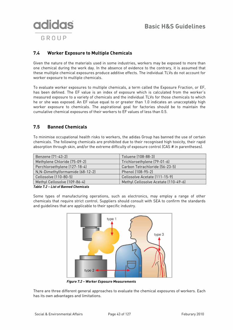
t as electronics, may employ a range of other hemicals that require strict control. Suppliers should consult with SEA to confirm the standards
Some ypes of manufacturing operations, suchcand guidelines that are applicable to their specific industry.
Figure 7.2 – Worker Exposure Measurements
There are three different general approaches to evaluate the chemical exposures of workers. Each
as its own advantages and limitations.
h
Social & Environmental Affairs Page 43 of 127 Feburary 2010
Basic H&S Guidelines
7.5.1 Type 1: Workplace Area Measurements
onitoring on workers.
his type of measurement is performed with a collection device, such as an organic vapour badge, hich is worn by workers in the vicinity of their breathing zones (i.e. near their mouths/noses). If is monitoring is conducted over the entire course of a workday, then the exposure results may be
ompared to the TLVs. This type of monitoring accounts for worker mobility during the workday nd also for differences in an individual’s work practices that may impact a worker’s exposure.
his type of exposure measurement should be conducted on those workers who are believed to be t highest risk of exposure, because of the chemicals that they use, the conditions of their work tations, or other factors that may determine exposure. For more information on personal onitoring of workers for VOC exposures, factories should consult their SEA representatives.
.5.3 Type 3: Medical Surveillance
he ultimate measure of exposure to chemicals may be an evaluation of the worker’s body: blood r urine analysis, diagnostic testing or other appropriate medical examination. Biological onitoring of workers may reveal the impact of all chemical exposures experienced by the orkers, and not solely those from the factory.
ker exposures to chemicals would involve a edical surveillance may be required in some
ountries for specific industries or chemical exposures.
This type of measurement is recorded at fixed positions throughout the factory, and thus likely does not represent the actual exposure of any individual worker. However, area measurements provide a determination of general conditions in the factory, and can identify the locations at which it may be prudent to perform personal exposure m 7.5.2 Type 2: Personal Monitoring of Workers
Twthca Tasm 7
Tomw A reasonably thorough evaluation of possible worombination of Type 1 and Type 2 measurements. Mc
c
Social & Environmental Affairs Page 44 of 127 Feburary 2010
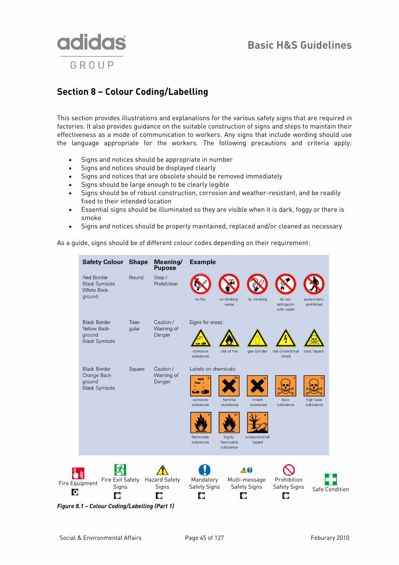
Basic H&S Guidelines
Section 8 – Colour Coding/Labelling
This section provides lustrations and explanations for the various safety sign that are required in
e suitable construction of signs and steps to maintain their ffectiveness as a mode of communication to workers. Any signs that include wording should use e language appropriate for the workers. The following precautions and criteria apply:
• Signs and notices should be appropriate in number • Signs and notices should be displayed clearly • Signs and notices that are obsolete should be removed immediately • Signs should be large enough to be clearly legible • Signs should be of robust construction, corrosion and weather-resistant, and be readily
fixed to their intended location • Essential signs should be illuminated so they are visible when it is dark, foggy or there is
smoke • Signs and notices should be properly maintained, replaced and/or cleaned as necessary
s a guide, signs should be of different colour codes depending on their requirement:
il sfactories. It also provides guidance on theth
A
Fire Equipment
Fire Exit Safety
Signs
Hazard Safety
Signs
Mandatory
Safety Signs
Multi-message
Safety Signs
Prohibition
Safety Signs
Safe Condition
Figure 8.1 – Colour Coding/Labelling (Part 1)
Social & Environmental Affairs Page 45 of 127 Feburary 2010
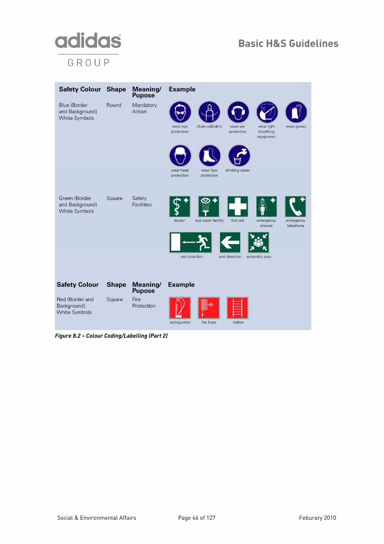
Basic H&S Guidelines
Figure 8.2 – Colour Coding/Labelling (Part 2)
Social & Environmental Affairs Page 46 of 127 Feburary 2010
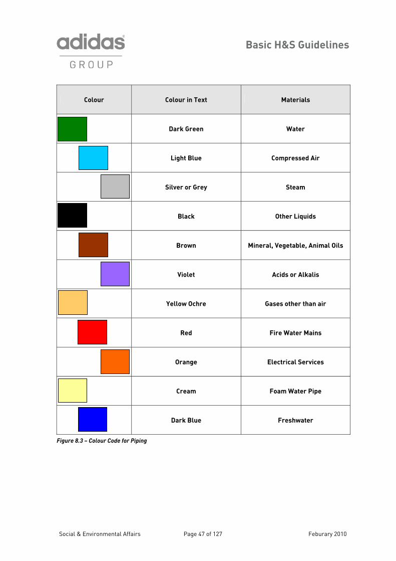
Basic H&S Guidelines
Social & Environmental Affairs Page 47 of 127 Feburary 2010
Colour Colour in Text Materials
Dark Green Water
Light Blue Compressed Air
Silver or Grey Steam
Black Other Liquids
Brown Mineral, Vegetable, Animal Oils
Violet Acids or Alkalis
Yellow Ochre Gases other than air
Red Fire Water Mains
Orange Electrical Services
Cream Foam Water Pipe
Dark Blue Freshwater
Figure 8.3 – Colour Code for Piping
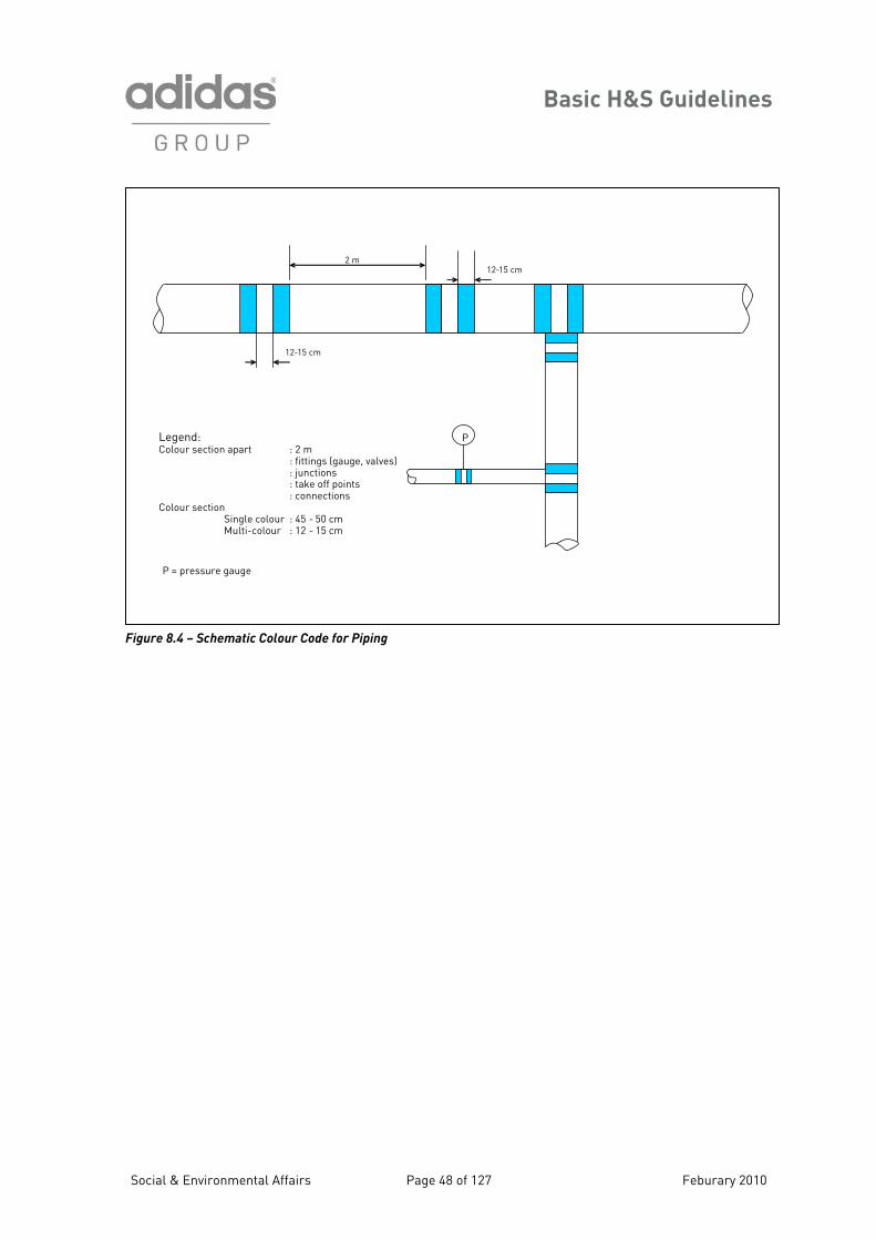
Basic H&S Guidelines
igure
12-15 cm2 m
12-15 cm
PLegend:Colo
: take off points: connections
ur section apart : 2 m: fittings (gauge, valves): junctions
Colour sectionSingle colour : 45 - 50 cmMulti-colour : 12 - 15 cm
P = pressure gauge
F 8.4 – Schematic Colour Code for Piping
Social & Environmental Affairs Page 48 of 127 Feburary 2010
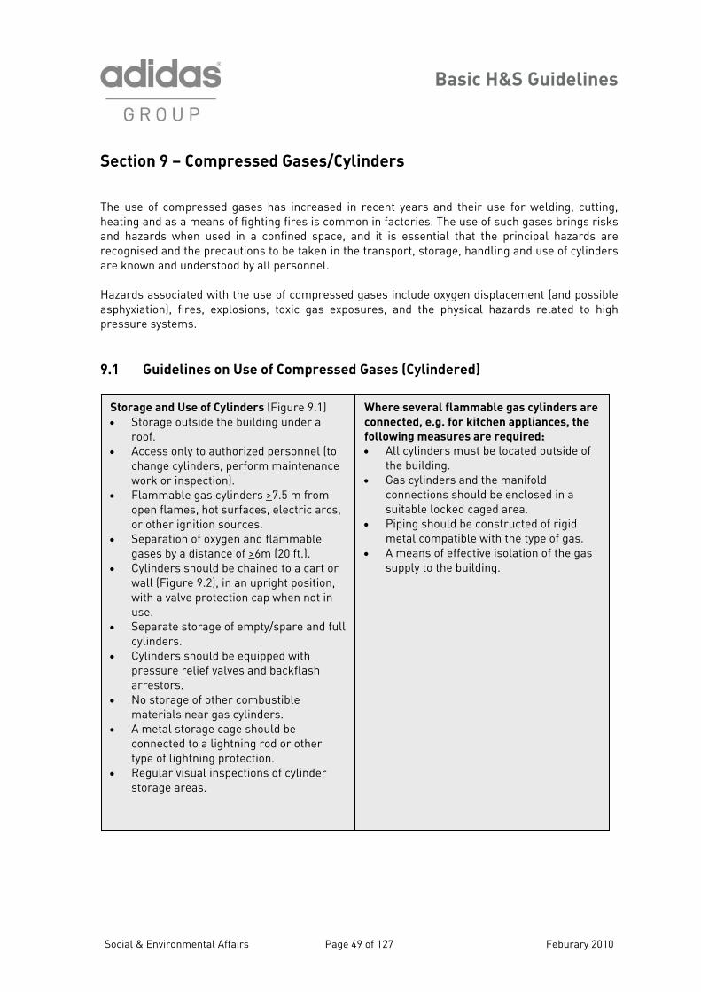
Basic H&S Guidelines
Section 9 – Compressed Gases/Cylinders
9.1 Guidelines on Use of Compressed Gases (Cylindered)
The use of compressed gases has increased in recent years and their use for welding, cutting, heating and as a means of fighting fires is common in factories. The use of such gases brings risks and hazards when used in a confined space, and it is essential that the principal hazards are recognised and the precautions to be taken in the transport, storage, handling and use of cylinders are known and understood by all personnel. Hazards associated with the use of compressed gases include oxygen displacement (and possible asphyxiation), fires, explosions, toxic gas exposures, and the physical hazards related to high pressure systems.
Storage and Use of Cylinders (Figure 9.1) • Storage outside the building under a
roof. • Access only to authorized personnel (to
change cylinders, perform maintenance work or inspection).
• Flammable gas cylinders >7.5 m from open flames, hot surfaces, electric arcs, or other ignition sources.
• Separation of oxygen and flammable gases by a distance of >6m (20 ft.).
• Cylinders should be chained to a cart or wall (Figure 9.2), in an upright position, with a valve protection cap when not in use.
• Separate storage of empty/spare and full cylinders.
• Cylinders should be equipped with ash
arrestors. • No storage of other combustible
materials near gas cylinders. • A metal storage cage should be
connected to a lightning rod or other type of lightning protection.
• Regular visual inspections of cylinder storage areas.
Where several flammable gas cylinders are
connected, e.g. for kitchen appliances, the
following measures are required:
• All cylinders must be located outside of the building.
• Gas cylinders and the manifold connections should be enclosed in a suitable locked caged area.
• Piping should be constructed of rigid metal compatible with the type of gas.
• A means of effective isolation of the gas supply to the building.
pressure relief valves and backfl
Social & Environmental Affairs Page 49 of 127 Feburary 2010
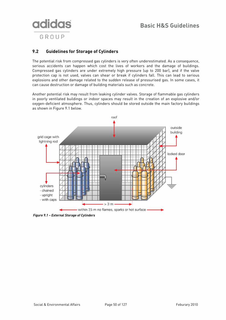
Basic H&S Guidelines
9.2 Guidelines for Storage of Cylinders
& Environmental Affairs Page 50 of 1 burary 2010
emely high pressure (up to 200 bar), and if the valve rotection cap is not used, valves can shear or break if cylinders fall. This can lead to serious xplosions and other damage related to the sudden release of pressurised gas. In some cases, it
can cause destruction or damage of building mate ials such as concrete.
nother p om leaking cylinder valves. Storage of flammable gas cylinders poorly ventilated buildings or indoor spaces may result in the creation of an explosive and/or
xygen-deficient atmosphere. Thus, cylinders should be stored outside the main factory buildings s shown in Figure 9.1 below.
The potential risk from compressed gas cylinders is very often underestimated. As a consequence, serious accidents can happen which cost the lives of workers and the damage of buildings. Compressed gas cylinders are under extrpe
r
otential risk may result frAinoa
Figure 9.1 – External Storage of Cylinders
Social 27 Fe
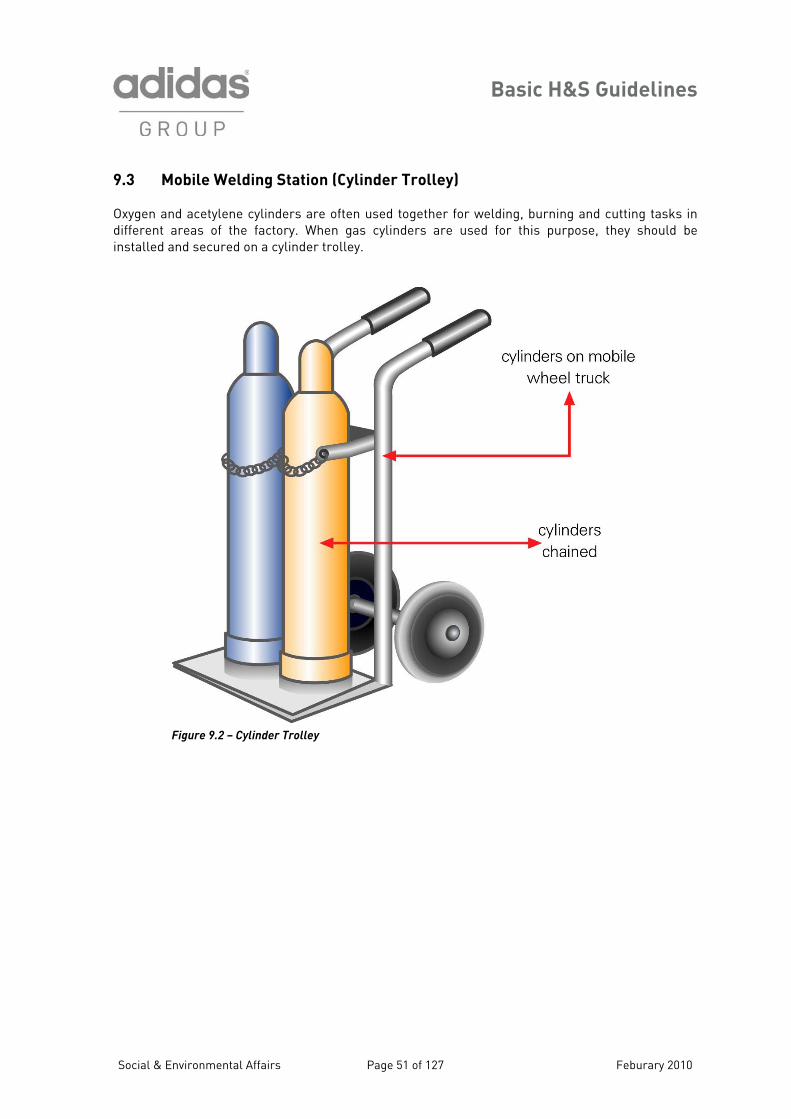
Basic H&S Guidelines
9.3 Mobile Welding Station (Cylinder Trolley)
xygen and acetylene cylinders are often used together for welding, burning and cutting tasks in ifferent areas of the factory. When gas cylinders are used for this purpose, they should be stalled and secured on a cylinder trolley.
Odin
Figure 9.2 – Cylinder Trolley
Social & Environmental Affairs Page 51 of 127 Feburary 2010
Basic H&S Guidelines
Section 10 – General Housekeeping/Lighting/Electricity Occupational accidents can be avoided with proper planning and maintenance of lighting, electricity and other utilities. The following sections outline the basic considerations to be taken into account in the management and maintenance of such installations and utilities. 10.1 Electrical Safety Regular maintenan trical installations and other utilitie ment in t dustrial accidents. Electrical safety is associa y with fire safety. O ed electrical wiring can lead to fire 1
10.3 General Housekeeping and Equipment
Reasonable housekeeping practices can reduce the number of fire and safety hazards in the factory. Such practices typically reflect the level of factory management interest in worker safety.
ce an repair of elecd s is a basic elehe avoidance of in ted closel
s. verloaded or improperly maintain
0.2 Guidelines on Electrical Safety
Electricity and Wirin
• Junction boxes, distribution panels and similar electrical equipment should be enclosed, dam nd should not be misused for d nnection to machines.
conneing should be insulated, replaced
and protected from mechanical damage (e.g. metal cable trays) and from extreme heat.
• There should be a regular inspection and maintenance programme for all electrical equipment.
High Voltage Areas and Generator Houses
• Restricted access to authorised workers only.
g signs (refer ection 8).
storage in high voltage
production areas, preferably at locations outside the building.
• They should be in enclosed areas, even if outdoors, to reduce the noise emissions.
• They should be equipped with a drip pan to prevent oil leaks to the ground.
• The belt drive systems should be totally enclosed or guarded.
• Air filters should be installed on the intake side.
• Motors should be kept free of dust, grease, oil and fibers.
• Appropriate hazard warninto S
• No materialareas.
g
age-free, airect co
• All wiring should have proper industrial ctions.
Compressor Stations
• These should be separated from • All wir
if damaged,
Social & Environmental Affairs Page 52 of 127 Feburary 2010
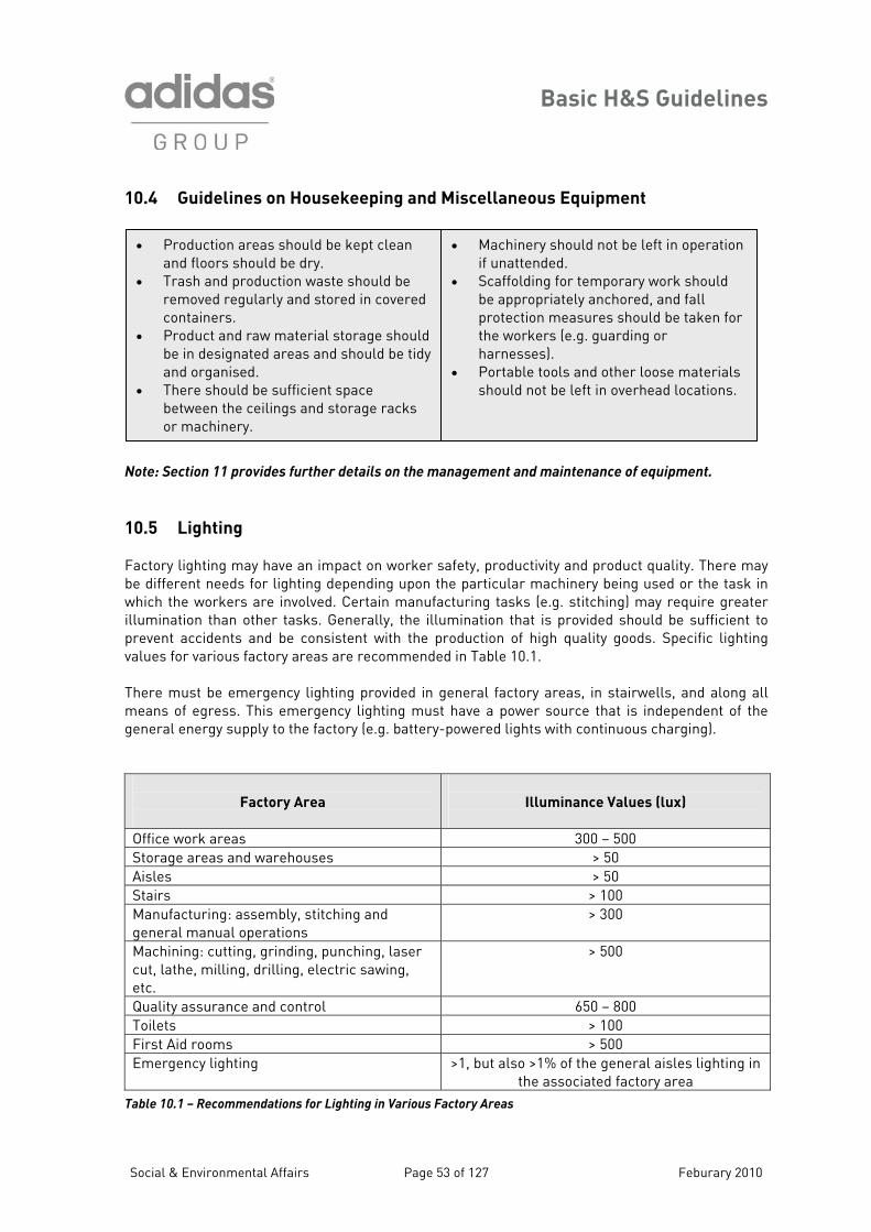
Basic H&S Guidelines
10.4 Guidelines on Housekeeping and Miscellaneous Equipment
Note: Section 11 provides further details on the management and maintenance of equipment.
10.5 Lighting Factory lighting may have an impact on worker safety, productivity and product quality. There may be different needs for lighting depending upon the particular machinery being used or the task in which the workers are involved. Certain manufacturing tasks (e.g. stitching) may require greater illumination than other tasks. Generally, the illumination that is provided should be sufficient to prevent accidents and be consistent with the production of high quality goods. Specific lighting values for various factory areas are recommended in Table 10.1. There must be emergency lighting provided in general factory areas, in stairwells, and along all means of egress. This emergency lighting must have a power source that is independent of the general energy supply to the factory (e.g. battery-powered lights with continuous charging).
• Production areas should be kept clean and floors should be dry.
• Trash and production waste should be removed regularly and stored in covered containers.
• Product and raw material storage should
Factory Area
Illuminance Values (lux)
Office work areas 300 – 500 Storage areas and warehouses > 50 Aisles > 50 Stairs > 100 Manufacturing: assembly, stitching and general manual operations
> 300
Machining: cutting, grinding, punching, laser cut, lathe, milling, drilling, electric sawing, etc.
> 500
Quality assurance and control 650 – 800 Toilets > 100 First Aid rooms > 500 Emergency lighting >1, but also >1% of the general aisles lighting in
the associated factory area Table 10.1 – Recommendations for Lighting in Various Factory Areas
be in designated areas and should be tidy and organised.
• There should be sufficient space between the ceilings and storage racks or machinery.
• Machinery should not be left in operation if unattended.
• Scaffolding for temporary work should be appropriately anchored, and fall protection measures should be taken for the workers (e.g. guarding or
esses). able tools and other loose materials
should not be left in overhead locations.
harn• Port
Social & Environmental Affairs Page 53 of 127 Feburary 2010
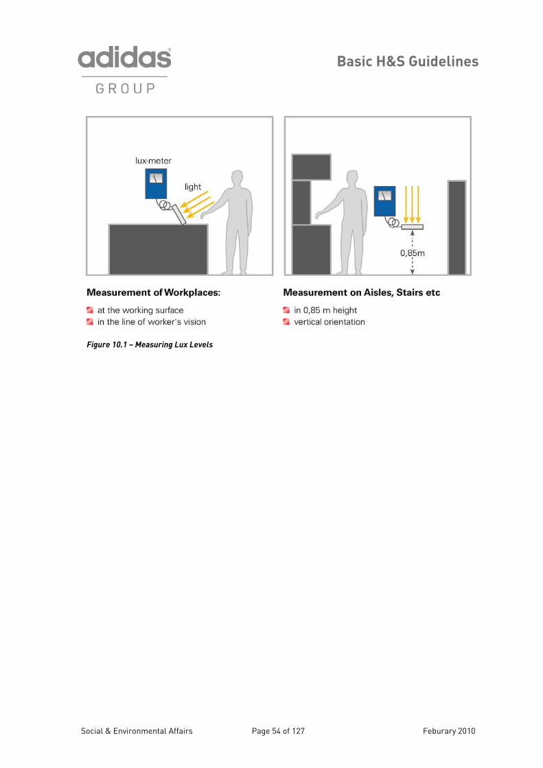
Basic H&S Guidelines
Figure 10.1 – Measuring Lux Levels
Social & Environmental Affairs Page 54 of 127 Feburary 2010
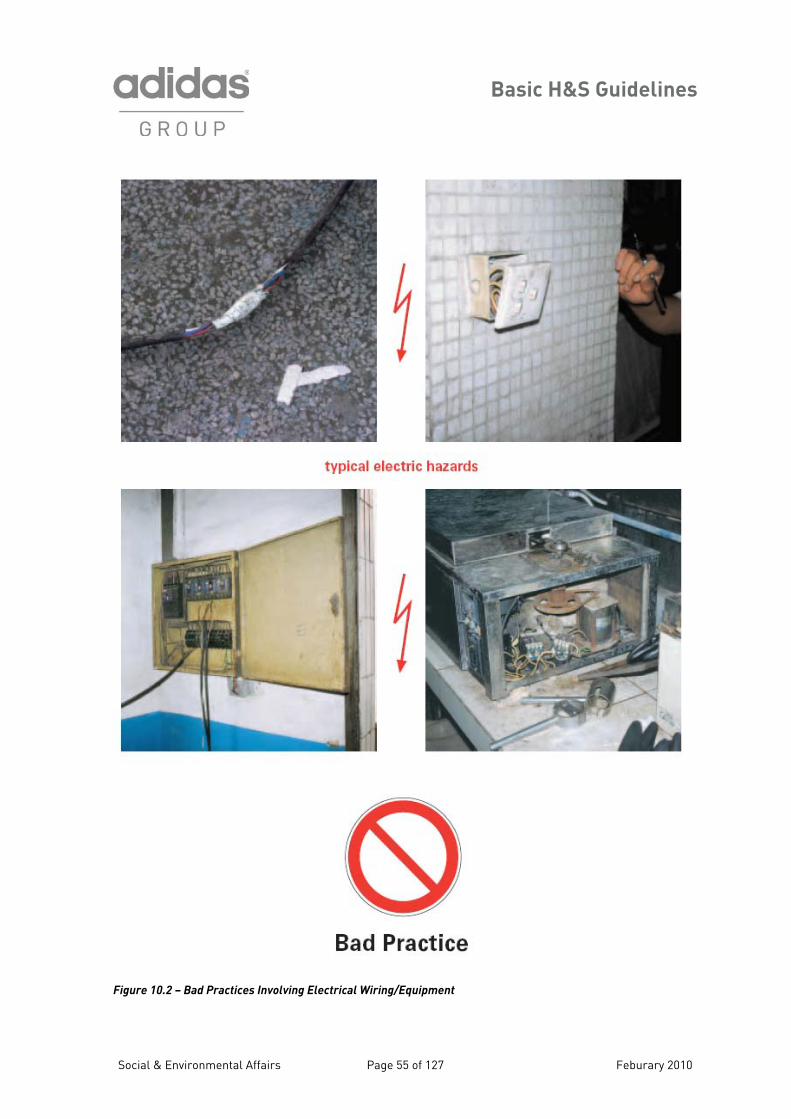
Basic H&S Guidelines
Figure 10.2 – Bad Practices Involving Electrical Wiring/Equipment
Social & Environmental Affairs Page 55 of 127 Feburary 2010
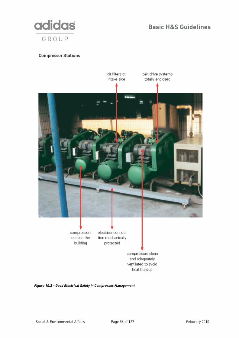
Basic H&S Guidelines
Figure 10.3 – Good Electrical Safety in Compressor Management
Social & Environmental Affairs Page 56 of 127 Feburary 2010
Basic H&S Guidelines
Section 11 – Machine Safety and Noise
The machinery that is used in factories may present a wide array of safety and health hazards to e workers. These hazards may be physical, electrical, thermal, auditory, or of other nature. The o basic principles of hazard control that should be consid machine
haza the risk the machines, and (2) prot the workers with appr PE) that is specific for th r risk. 11.1 General Guidelines for Machine Safety
lectrical safety should be a continuing concern when operating equipment. Electric current owing through the body can cause shock, burns, and breathing difficulty. The alternating current t electrical mains (240 volts AC) is sufficient to cause fatal exposures. Flash burns can be caused y opening switches, removing fuses or shortening cables. Ignition hazards may result from lectrical faults, short circuits, poor contacts, overloaded cables or connections, and other faulty quipment.
thtw ered in the reduction of
fitting safety devices or guardrds are: (1) elimination or reduction of by s toopriate personal protective equipment (Pection of
e particula
• All machinery and lighting should be connected to their power source with appropriate industrial connections.
• The machinery should be grounded (e.g. third prong).
• Permanent electrical wiring should be
• Working tools should be provided with appropriate protective devices to prevent injury to workers from squeezing, cuts or burns.
• Local exhaust ventilation for the extraction of dusts or solvent vapours
encased in a metal conduit.
should include a list of the required PPE and the emergency shut-down
procedures. • There should be regular inspection and
maintenance of all production machinery to ensure that all safety devices and mechanisms are effective, and inspection and maintenance records should be maintained by the factory.
• Appropriate lockout/tagout procedures should be implemented during all equipment maintenance and repair work (refer to Section 20).
should be provided by separate systems,
should wear certified steel-toed safety
shoes.
• Appropriate gloves should be provided to protect workers’ hands from mechanical, chemical or thermal hazards.
• Individual machines should have their own emergency power shut-off switch within easy reach of the usual operator position.
• All gear boxes should be enclosed, and only opened with special tools.
• There should be machine safety training for all workers before they are allowed to operate any machine. This training
and the ductwork should be identified by different colours.
• Eye protection should be worn by workers when there is risk of injury from flying particles or dust, splashed chemicals, or persistent glare or ultraviolet radiation.
• Workers who operate mobile equipment or forklift trucks or lift heavy items
E
flabee
Social & Environmental Affairs Page 57 of 127 Feburary 2010

Basic H&S Guidelines
Physical hazards to the workers may arise from exposure to the point of operation on a particular achine or from other moving parts on the same machine. Compression, cutting or shearing of
ands, feet, hair or other body parts can occur. Risk of impact to the eyes, face or other body parts ay be caused by flying objects in grinding or buffing operations, wires from wheel brushes, or
ther tools (e.g. needles in stitching or sewing areas). To minimise the likelihood of these types of juries to workers, the following specific recommendations are provided for certain machinery.
1.2 Specific Guidelines for Machine Safety
hermal hazards may be created by a variety of factory operations, such as steam systems or achinery operation that creates hot surfaces. Hot surfaces, pipes or other equipment should be arke signs. The degree of the depends upon e co ivity of the surface. Meta ermal energy
ery well and therefore could cause a greater hazard than wooden p e temperature. or the purpose of the H&S Guidelines, “hot surface fined as follows:
• Wooden parts or surfaces: >110oC • Plastic parts or surfaces: >85oC • Metal parts or surfaces: >60oC
otential hazards from ultraviolet (UV) radiation may arise from the use of UV or “black” lights in ould be shielded to prevent line-of-sight exposure to workers’
yes. Also, workers at UV stations should be provided with special UV protective goggles or olycarbonate safety glasses that are rated at >98% UV reduction. (Refer to the “bad practice” hotographs at the end of this section.)
mhmoin 1
• There should be fixed guards or covers for all V-belt drives, pulleys, and buffing and grinding machines.
• There should be needle and pulley guards on sewing machines.
• There should be blade guards on cutting machines and table saws.
• Guards may be constructed of solid material or grids; if grids, then the openings must be <12 mm to prevent insertion of fingers.
• Two-hand switches should be used on all cutting machines, presses, and heat transfer machines unless guarding can be shown to be effective (a two-hand switch requires both hands to be on two buttons simultaneously for machine operation, thus removing the hands from the zone of exposure).
• It is important that the factory ensures that workers do not defeat or override the two-hand switch safety feature.
• Mills and calendars should be provided with multiple safety devices (see photographs for examples of good practices).
• Inter
stops l revolving drums and rollers.
• Electronic sensors that prevent machine operation or shut down power when body parts are detected in the zone of exposure are recommended as useful safety devices on appropriate machinery.
locked guards and emergency
should be provided on al
T
mm d with appropriate hazard warning
t thermal hazard l parts conduct th
arts at the samth ntact time and the thermal conducvF s” are de
Pproduction areas. Such UV lights shepp
Social & Environmental Affairs Page 58 of 127 Feburary 2010
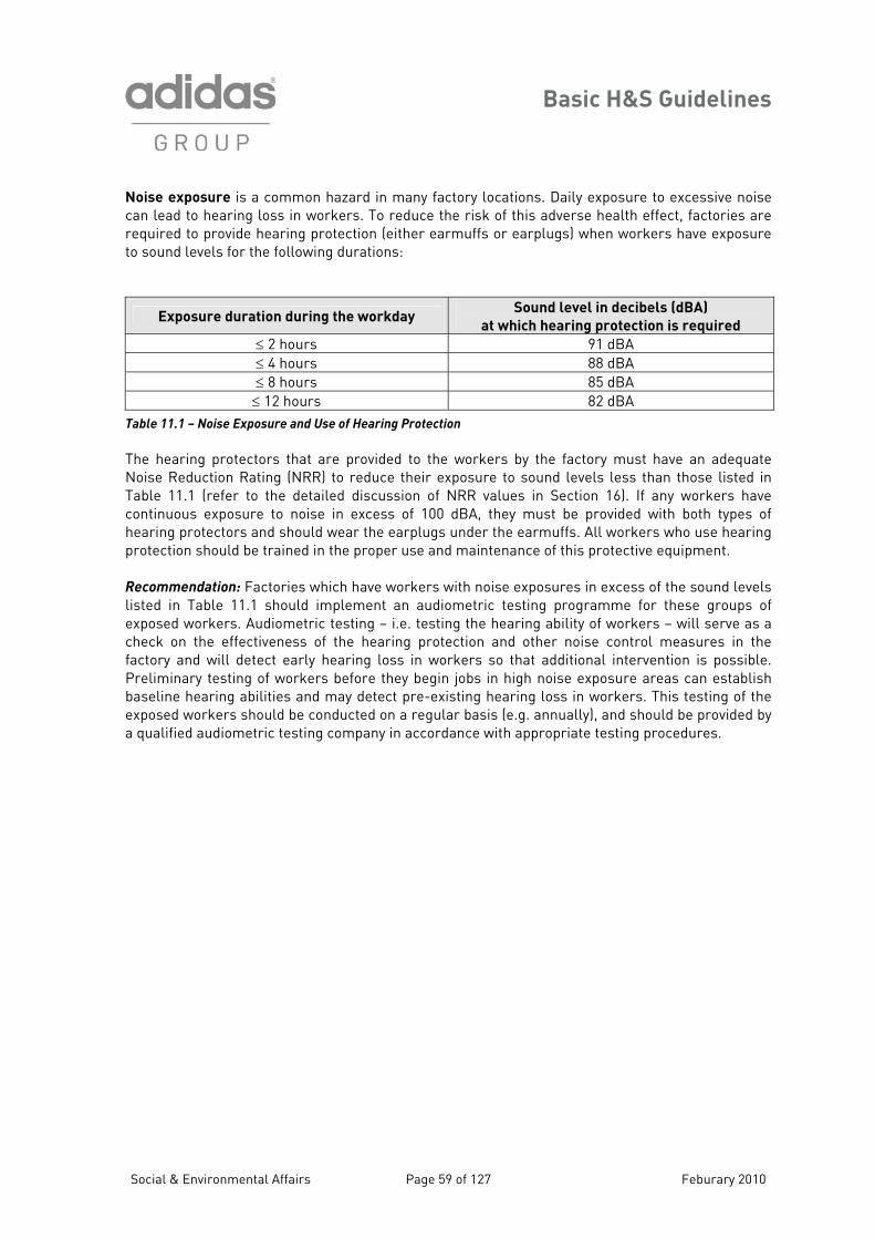
Basic H&S Guidelines
Noise exposure is a common hazard in many factory locations. Daily exposure to excessive noise an lead to hearing loss in workers. To reduce the risk of this adverse health effect, factories are equired to provide hearing protection (either earmuffs or earplugs) when wo re sound levels for the following durations:
cr rkers have exposuto
Exposure duration during the workday Sound level in decibels (dBA)
at which hearing protection is required
≤ 2 hours 91 dBA ≤ 4 hours 88 dBA ≤ 8 hours 85 dBA ≤ 12 hours 82 dBA
Table 11.1 – Noise Exposure and Use of Hearing Protection
he hearing protectors that are provided to the workers by the factory must have an adequate oise Reduction Rating (NRR) to reduce their exposure to sound levels less than those listed in able 11.1 (refer to the detailed discussion of NRR values in Section 16). If any workers have ontinuous exposure to noise in excess of 100 dBA, they must be provided with both types of earing protectors and should wear the earplugs under the earmuffs. All workers who use hearing rotection should be trained in the proper use and maintenance of this protective equipment.
ecommendation: Factories which have workers with noise exposures in exce ls sted in Table 11.1 should implement an audiometric testing programme of xposed workers. Audiometric testing – i.e. testing the hearing ability of workers – will serve as a heck on the effectiveness of the hearing protection and other noise control measures in the ctory and will detect early hearing loss in workers so that additional intervention is possible. reliminary testing of workers before they begin jobs in high noise exposure areas can establish aseline hearing abilities and may detect pre-existing hearing loss in workers. This testing of the xposed workers should be conducted on a regular basis (e.g. annually), and should be provided by qualified audiometric testing company in accordance with appropriate testing procedures.
TNTchp R ss of the sound leve
for these groups liecfaPbea
Social & Environmental Affairs Page 59 of 127 Feburary 2010
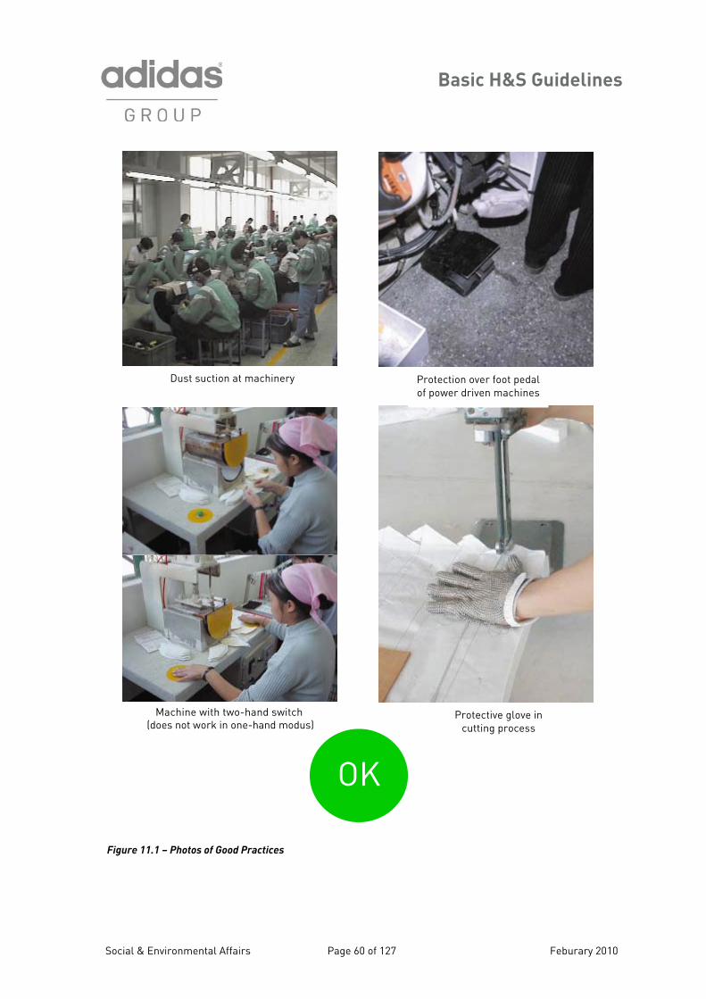
Basic H&S Guidelines
Figure 11.1 – Photos of Good Practices
Dust suction at machinery
Protective glove in cutting process
Machine with two-hand switch (does not work in one-hand modus)
OK
Protection over foot pedal of power driven machines
Social & Environmental Affairs Page 60 of 127 Feburary 2010
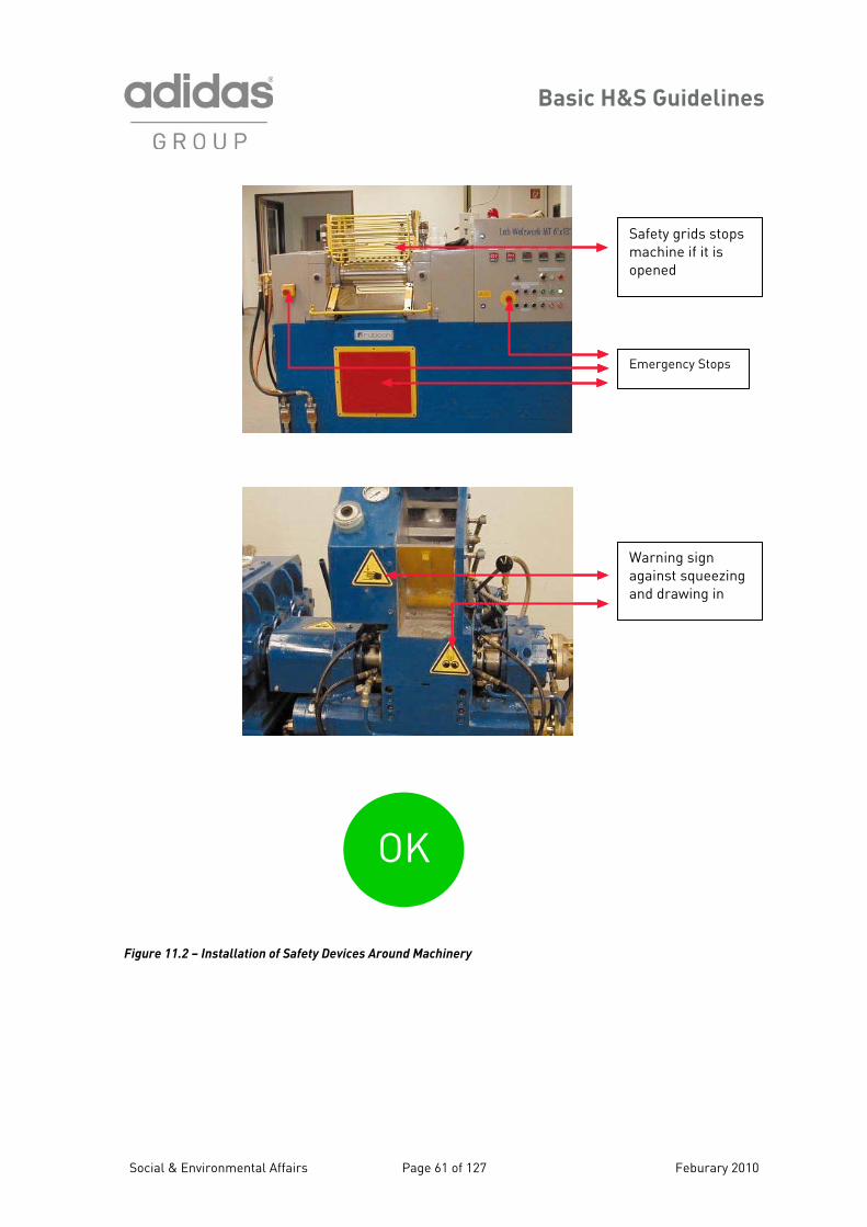
Basic H&S Guidelines
Figure 11.2 – Installation of Safety Devices Around Machinery
Warning sign against squeezing and drawing in
Safety grids stops machine if it is opened
Emergency Stops
OK
Social & Environmental Affairs Page 61 of 127 Feburary 2010
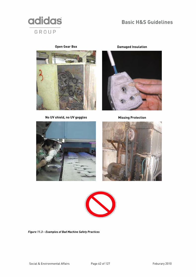
Basic H&S Guidelines
igure 11.3 – Examples of Bad Machine Safety Practices
Open Gear Box
No UV shield, no UV goggles Missing Protection
Damaged Insulation
F
Social & Environmental Affairs Page 62 of 127 Feburary 2010
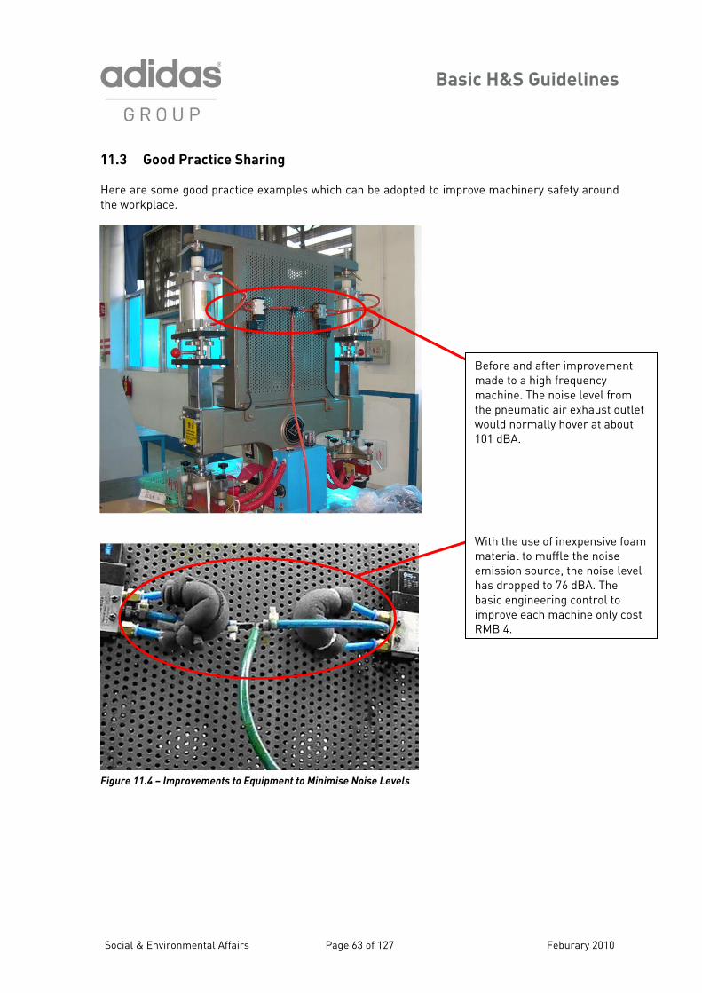
Basic H&S Guidelines
11.3 Good Practice Sharing Here are some good practice examples which can be adopted to improve machinery safety around the workplace.
Figure 11.4 – Improvements to Equipment to Minimise Noise Levels
Before and after improvement made to a high frequency machine. The noise level from the pneumatic air exhaust outlet would normally hover at about 101 dBA.
e of inexpensive foam ffle the noise
ource, the noise level ed to 76 dBA. The
eering control to machine only cost
With the usmaterial to muemission shas droppbasic enginimprove eachRMB 4.
Social & Environmental Affairs Page 63 of 127 Feburary 2010
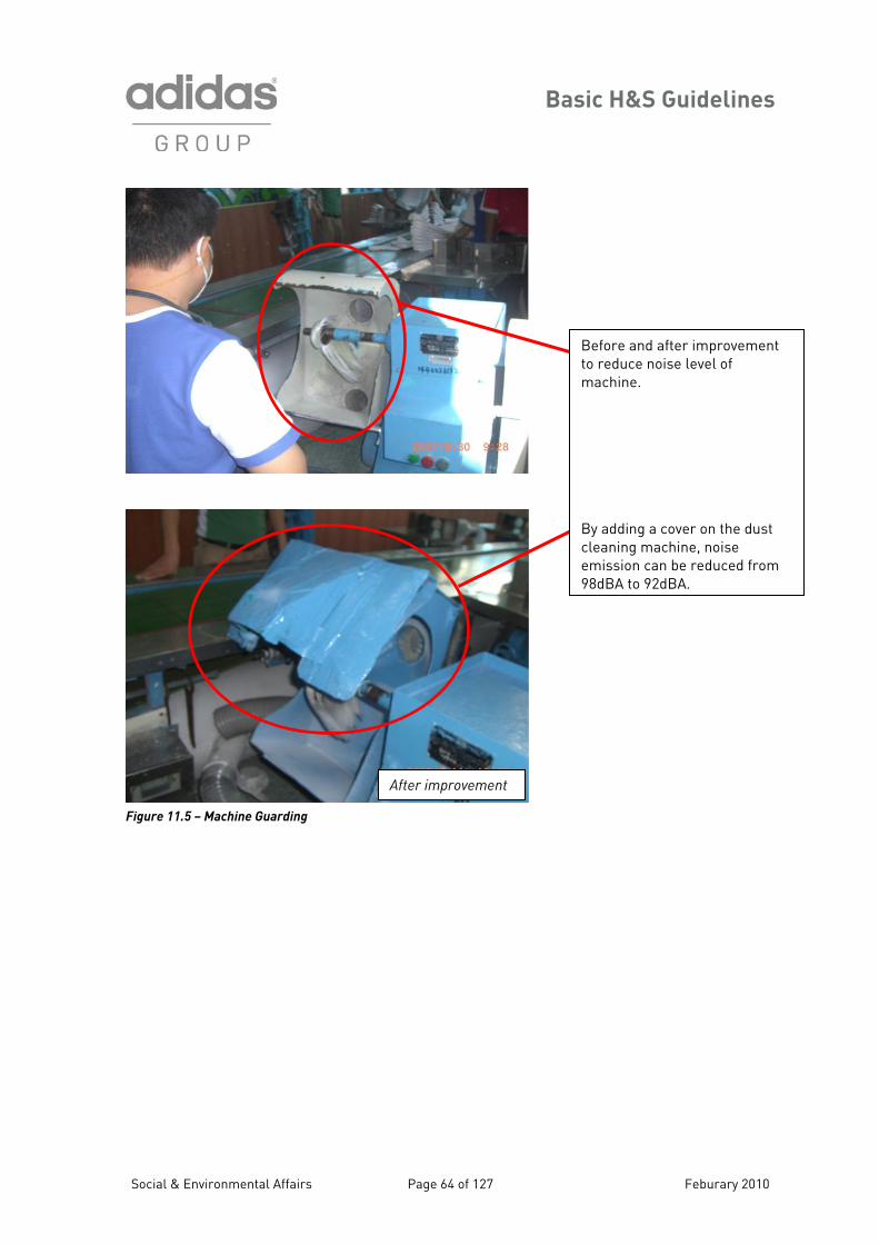
Basic H&S Guidelines
Figure 11.5 – Machine Guarding
After improvement
Social & Environmental Affairs Page 64 of 127
Before andto reduce nmachine. By adding a cover on the dust cleaning machine, noise emission can be reduced from98dBA to 92dBA.
after improvementoise level of
Feburary 2010
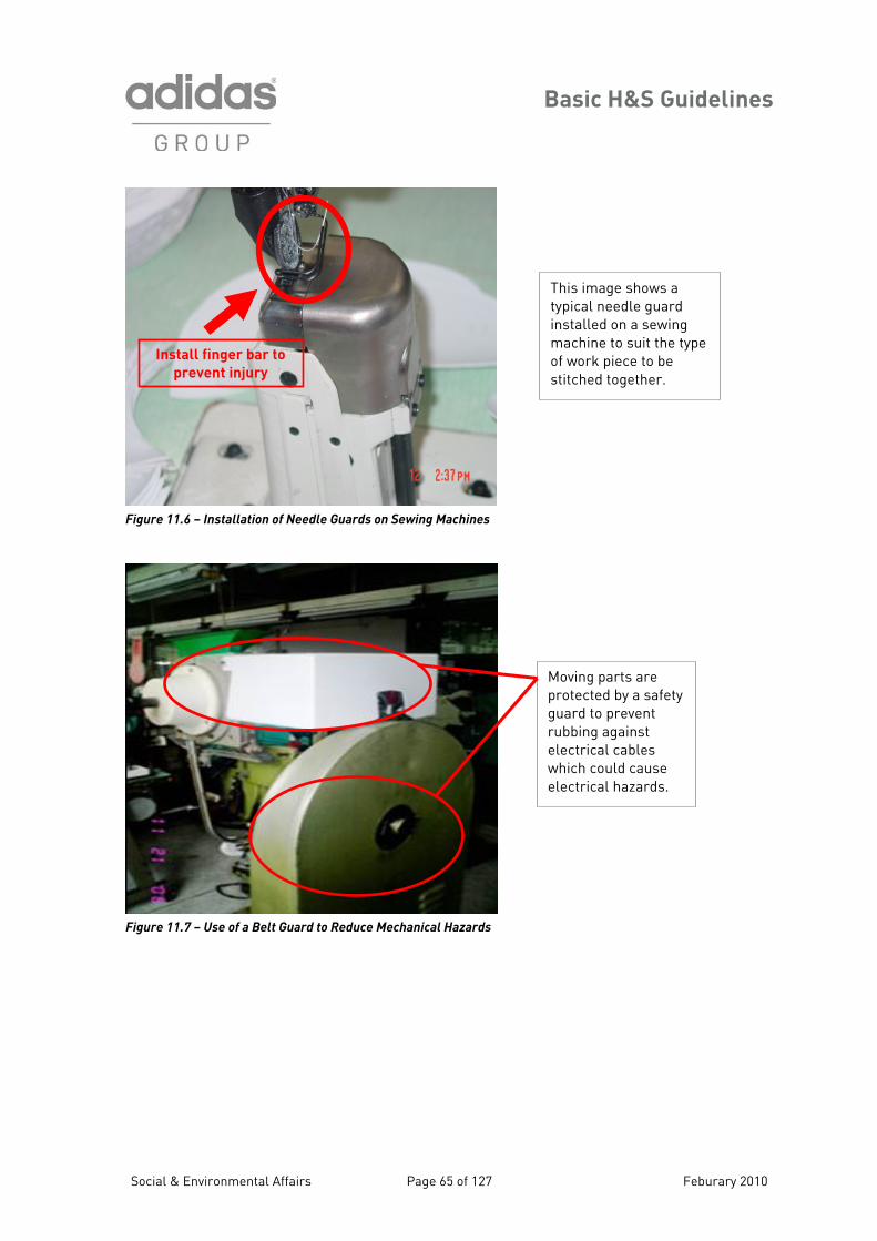
Basic H&S Guidelines
igure 11.6 – Installation of Needle Guards on Sewing Machines F
Figure 11.7 – Use of a Belt Guard to Reduce Mechanical Hazards
Install finger bar to
prevent injury
This image shows a typical needle guard installed on a sewing machine to suit the type of work piece to be stitched together.
Moving parts are protected by a safety guard to prevent rubbing against electrical cables which could cause electrical hazards.
Social & Environmental Affairs Page 65 of 127 Feburary 2010
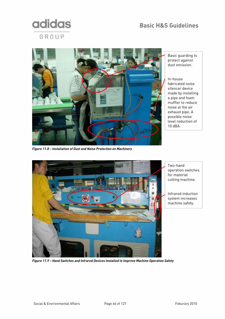
Basic H&S Guidelines
Basic guarding to protect against dust emission In-house fabricated
.
noise silencer device made by installing a pipe and foam muffler to reduce noise at the air exhaust pipe. A possible noise level reduction of 10 dBA.
Figure 11.8 – Installation of Dust and Noise Protection on Machinery
Two-hand operation switchesfor material cutting machine.
Infrared induction system increasesmachine safety.
Figure 11.9 – Hand Switches and Infrared Devices Installed to Improve Machine Operation Safety
Social & Environmental Affairs Page 66 of 127 Feburary 2010
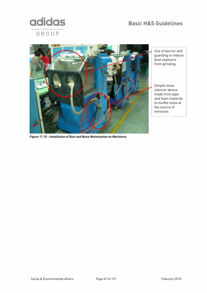
Basic H&S Guidelines
Social & Environmental Affairs Page 67 of 127 Feburary 2010
Use of barrier and guarding to reduce dust exposure
m grinding.
made from pipe and foam material
muffle noise at the source of emission.
fro Simple noise silencer device
to
Machinery Figu 11.10 – Installation of Dust and Noise Minimisare tion on
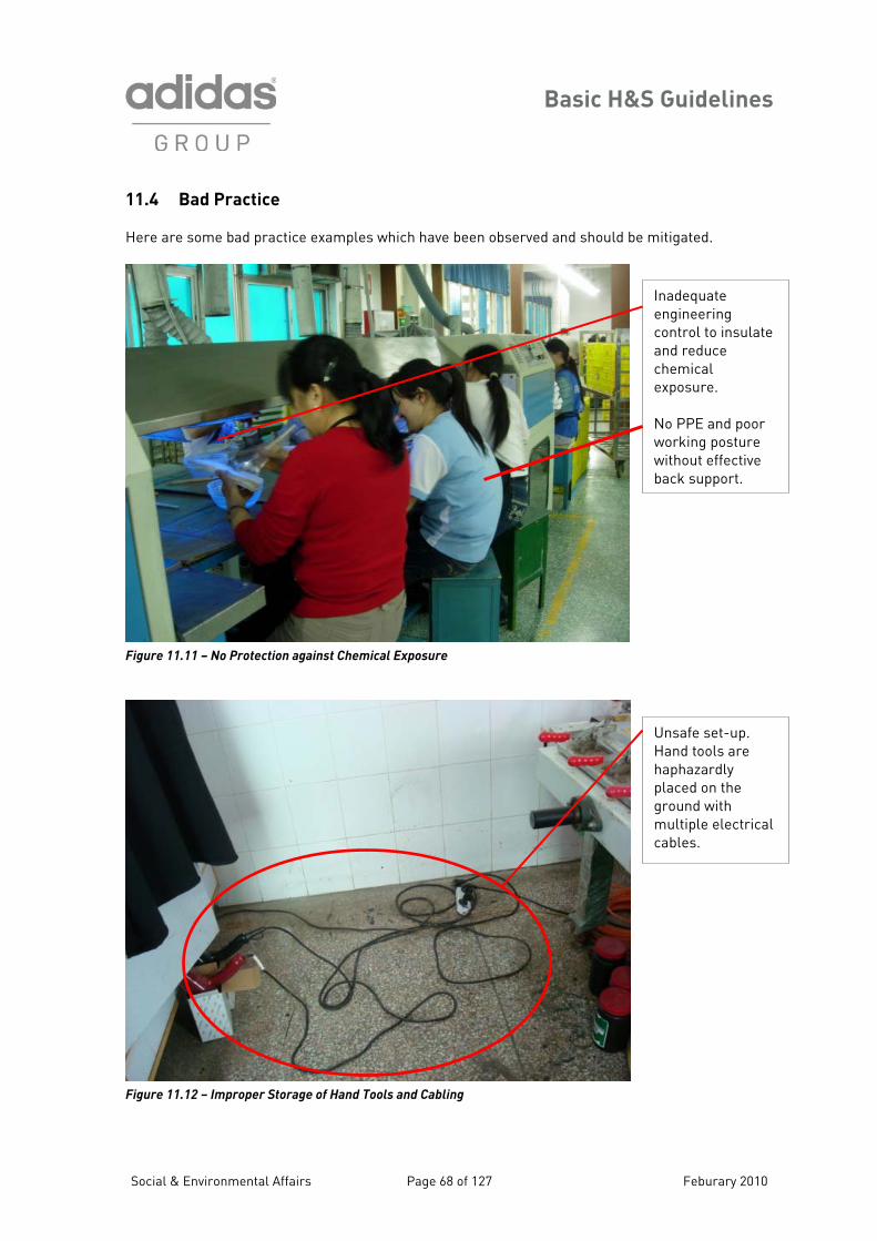
Basic H&S Guidelines
11.4 Bad Practice Here are some bad practice examples which have d and should be mitigated. been observe
Figure 11.11 – No Protection against Chemical Exposure
Figure 11.12 – Improper Storage of Hand Tools and Cabling
Social & Environmental Affairs Page 68 of 127
Inadequate engineering
late
emical
No PPE and poor osture
e back support.
control to insuand reduce chexposure.
working pwithout effectiv
Unsafe set-up. Hand tools are
ed on the
rical
haphazardly placground with multiple electcables.
Feburary 2010
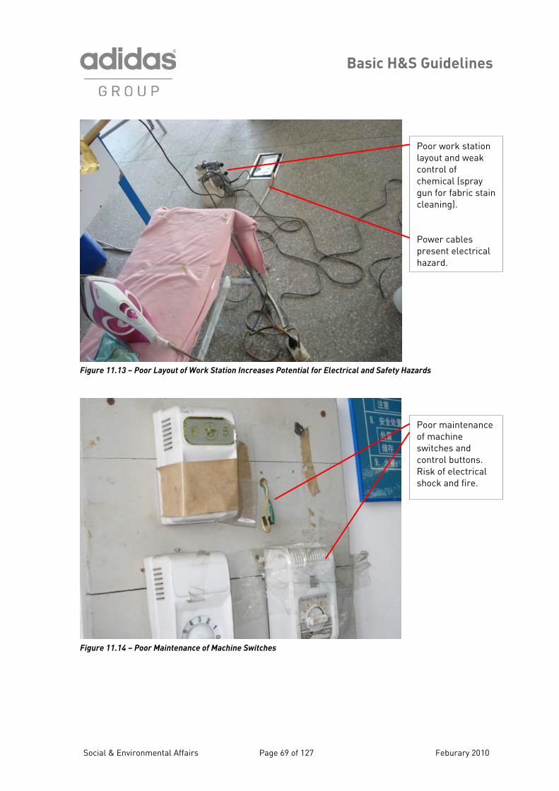
Basic H&S Guidelines
Figure 11.13 – Poor Layout of Work Station Increases Potential for Electrical and Safety Ha
Figur
e 11.14 – Poor Maintenance of Machine Switches
Social & Environmental Affairs Page 69 of 127
Poor work station layout and weak control of chemical (spray gun for fabric staincleaning). Power cables present electrical hazard.
zards
Poor maintenanceof machine switches and control buttons. Risk of electrical shock and fire.Feburary 2010
Basic H&S Guidelines
Section 12 – Dormitory Facilities
operated by the factory should meet these H&S Guidelines and all pplicable laws and regulations related to health, safety and the environment, including, but not mited to, fire safety, sanitation, risk protection and electrical, mechanical and structural safety.
her, dormitory conditions should reflect the interest of factory management in providing living kers and enhance the reputation and image of the
ctory. Dormitory buildings should be safe, clean and well-maintained.
2.1 Guidelines for Dormitory Facilities
ach room used for sleeping purposes should be provided with proper lighting, heating and ntilation for the comfort and safety of the residents.
Dormitory facilities that arealiFurtarrangements which promote the dignity of worfa 1
General
• Every dormitory shall be constructed in a manner that will provide occupants with protection against extreme weather conditions.
• Any building license/permit as required by local regulation should be available and updated.
• The floors shall be constructed of wood, asphalt or concrete. Wooden floors should be smooth and of tight construction. Floors should be kept in good repair.
• The grounds and open areas surrounding the dormitory should be maintained in a clean and sanitary condition, free from rubbish.
Sleeping Quarters
• Sleeping quarters should be segregated
by gender. • Each room used for sleeping purposes
shall contain at least 2 square meters of floor space per occupant, or should satisfy the local legal requirement if that provides for greater space.
• The ceiling height should be at least 2.1 meters above the floor.
• There should be no more than 8 people per room (no openings between rooms).
• Beds, cots or bunks, and suitable storage facilities such as wall lockers, should be provided in every room that is used for sleeping purposes.
• Each resident should have their own bed,
n 1 meter laterally (for bunk beds, 1.2 m).
• All beds should be elevated at least 0.3 meters from the floor.
Triple bunk beds are prohibited.
acy.
• Any storage areas for waste that is collected in the dormitories should be separate
• Dormitory
cot or bunk. • Beds should be spaced no closer tha
from living quarters. rooms must not be locked
from the outside at night, but residents
• should be accessible in all
• The building and its facilities should have o
should be allowed to secure locks from the inside of rooms.
• Storage of hazardous or combustible materials is prohibited in dormitories. First Aid kits
• Double-decker bunk beds should have a minimum clearance of 0.7 meters between the upper and lower bunks, and between the upper bunk and the ceiling.
dormitories and supplied with the materials specified in Section 4 of these Guidelines.
• At least 1% of dormitory residents should be trained in First Aid.
• Storage facilities should be lockable. • Mosquito netting or window screens
should be provided. • Recommendation: Curtains should be
provided around each bed for priv
n material containing asbestos.
Eve
Social & Environmental Affairs Page 70 of 127 Feburary 2010
Basic H&S Guidelines
Lighting:
• Each sleeping room in a dormitory should have at least ceiling-type lighting fixtures.
• Each laundry, kitchen, toilet or other room where residents may congregate should have at least one ceiling or wall light fixture.
• Light levels in toilets and storage rooms should be at least 20 lux, and light levels in kitchens, sleeping rooms, and other rooms should be at least 30 lux (as measured 0.75m from the floor).
Heating:
• Recommendation: Every dormitory in cold climates should be provided with equipment that is capable of maintaining a temperature of at least 20oC in indoor spaces.
• All heating systems must be well-maintained and safe to operate.
Ventilation:
• All sleeping quarters should be provided with windows, the total area of which should amount to at least one-tenth (10%) of the floor area of the space.
• At least half of the window area should be constructed so that it may be opened for purposes of ventilation.
• The windows must open to the outdoors or an outside courtyard, but may not open to an interior space.
• In hot climates (>25oC), appropriate electrical fans or air conditioning should be provided.
The suitability of other facilities within the dormitory building may also be significant for the health, afety and comfort of the residents. An adequate and convenient water supply which has been pproved by the appropriate local health authority should be provided to each dormitory building r the purposes of drinking, cooking, bathing and laundry.
oilets, laundry areas, and garbage/trash accumulation containers also should have features that re consistent with the practical needs as well as the health and safety needs of the dormitory esidents.
r facilities within the dormitory building may also be significant for the health, afety and comfort of the residents. An adequate and convenient water supply which has been pproved by the appropriate local health authority should be provided to each dormitory building r the purposes of drinking, cooking, bathing and laundry.
oilets, laundry areas, and garbage/trash accumulation containers also should have features that re consistent with the practical needs as well as the health and safety needs of the dormitory esidents.
ssaafofo
Water Supply:
• The water supply is “adequate” if it is capable of delivering 130 liters of water per person per day to the dormitory. The peak rate capacity should be 2.5 times the average hourly demand.
• The distribution lines should be capable of supplying water at normal operating pressures to all fixtures for simultaneous operation.
• An adequate supply of hot and cold running water should be provided for bathing and laundry purposes. Facilities for heating water should be provided. Tepid water supply is acceptable for laundry equipment.
• At least one handwash basin for every 6 residents in shared facilities.
• At least one shower head for every 10 residents.
• Doors should be provided in the showers for privacy.
• An adequate supply of soap is required for handwashing and shower facilities.
• Recommendation: In locations that may have extended periods with temperatures <20oC, hot and cold water should be available from a single tap.
• Drinking water should be tested regularly if it is provided through an internal drinking water treatment facility, or to be completed with a certificate from the provider.
TTaarr
Social & Environmental Affairs Page 71 of 127 Feburary 2010
Basic H&S Guidelines
12.2 Guidelines for Other Facilities in Dormitory Buildings
Laundry:
• At a minimum, there should be one laundry tray or tub for every 30 residents. These may be available in laundry areas or at other convenient and accessible locations in the dormitory building.
• Facilities for the drying of clothes should be provided. This requirement is satisfied by having adequate sheltered space for the hanging of clothes to dry.
Floors:
• All floors in laundry, shower, toilet and handwashing areas should be constructed of smooth, but not slippery, materials which are impervious to moisture and easy to clean.
• Floor drains should be provided at these same locations (shower stalls, shower rooms, laundry rooms and toilet areas) to remove waste water and facilitate cleaning.
• All junctions of the curbing and the floor should be curved.
Garbage/Trash Containers:
• At least one container with cover should be provided for each dormitory room.
• The containers should be rodent and fly-proof and impervious to liquids, and should be kept clean.
• The containers should always be emptied when they are full, and no less than twice weekly.
Toilets:
• Refer to Section 13 – Sanitation and Hygiene: Toilet, Dining and Kitchen Facilities.
Finally, there are certain aspects of fire safety that are important in dormitories.
Fire Safety:
• Aisles and exits should be clear of obstructions, and exits should be marked clearly. • There should be at least two exit routes from each floor of the dormitory building. • All exit doors should be unlocked and sh ould open outward. • Emergency evacuation plans and emergency telephone numbers should be posted at
conspicuous locations. • tion and quired, and no Appropriate smoke detec fire alarm systems are re regularly
occupie n of the build portio ding should b an alarm button or pull box. e > m from 60• Emerg ting should be installed and operational. ency ligh• Sufficient fire extinguishing equipment should be available and should be ins ted pec
regularly. • Fire sa s, emergency evacuation pr edures, and training on the use of fire fety issue oc
exting some residents) should b ncluded in the resident orientation. uishers (for e i
Social & Environmental Affairs Page 72 of 127 Feburary 2010
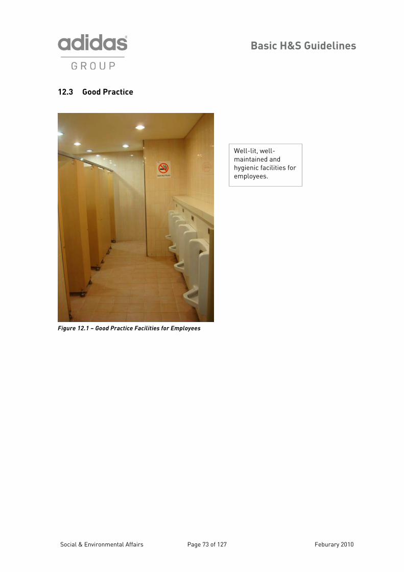
Basic H&S Guidelines
12.3 Good Practice
Well-lit, well-maintained and hygienic facilities for employees.
Figure 12.1 – Good Practice Facilities for Employees
Social & Environmental Affairs Page 73 of 127 Feburary 2010
Basic H&S Guidelines
Section 13 – Sanitation and Hygiene: Toilet, Dining and Kitchen
acilities
anitary conditions in toilets, bathrooms, food preparation and dining areas and throughout factory nd dormitory buildings are important for the protection of the health of the residents. The llowing guidelines apply to all production, development, office, warehouse and dormitory/
esidence areas at a facility.
he term ‘personal service room’ is used frequently in this section of the Guidelines. This term is tended to include any room that is used for activities that are not directly related to production. uch activities include, but are not limited to, first aid rooms, medical service areas or clinics,
3.2 Guidelines for Waste Disposal
F
Safor TinSdressing areas, showers and washing areas, toilets, food preparation and dining areas. 13.1 Guidelines for Building Construction
• All walls of personal service rooms should be tiled or clean
• To facilitate cleaning processes, every painted.
• Personal service rooms should have adequate ventilation to ensure that they are free of foul odors.
• Floors should be maintained, so far as practicable, in dry condition.
• Where wet processes are used, drainage should be provided and maintained, and platforms, false floors, mats or other dry standing places should be provided, where practicable, or appropriate wato
floor should be kept free from protruding nails, splinters, loose boards, and unnecessary holes or openings.
• Floors of personal service rooms should be sealed (tile or cement), slip-resistant, and wet-mopped at least twice per day with a cleaning solution containing a bacteriacide.
erproof footwear should be provided t the workers.
1
• Any receptacle that is used for solid or liquid waste should be constructed so that it does not leak and may be cleaned thoroughly in order to be maintained in a sanitary condition.
• All sweepings, solid or liquid wastes, refuse and garbage should be removed in such a manner as to avoid the creation of health risks, and as often as necessary to maintain sanitary conditions.
• Vermin control: Every enclosed area of a factory facility should be constructed, equipped and maintained, so far as practicable, to prevent the entrance or harbourage of rodents, insects and other vermin. A continuing and effective extermination programme should be implemented wherever and whenever their presence is detected.
Social & Environmental Affairs Page 74 of 127 Feburary 2010
Basic H&S Guidelines
The Guidelines address issues related to the water supply in two separate categories: potable rinking) water and non-potable water. (d
Potable Water: • Potable water should be provided in all
factories and dormitories for drinking, personal washing, cooking, and the washing of foods, cooking and eating utensils, food preparation and processing areas and personal service rooms.
• Drinking water dispensers should be designed, constructed, and serviced so that sanitary conditions are maintained. They should be capable of being closed, and equipped with a tap.
• The drinking water supply should not be located inside toilet areas.
• Open holding containers such as barrels, pails or tanks from which drinking water must be dipped or poured, whether they are fitted with a cover or not, are prohibited.
• A common drinking cup or other shared utensils are prohibited.
Non-Potable Water: • Outlets or spigots for non-potable water,
such as water for industrial or fire-fighting purposes, should be posted or otherwise marked in a manner that indicates clearly that the water is unsafe for use for other purposes, such as drinking, washing or laundry.
• Construction of non-potable water systems should be such as to prevent back-flow or back-siphonage into any potable water system.
• Non-potable water should never be used for personal washing, the washing of cooking and eating utensils, and laundry.
• Non-potable water may be used for the cleaning of work areas other than food processing and preparation areas and personal service rooms, provided that it does not contain concentrations of chemicals, fecal coliform (bacteria from feces), or other substances that could create unsanitary conditions or be harmful to workers.
Social & Environmental Affairs Page 75 of 127 Feburary 2010
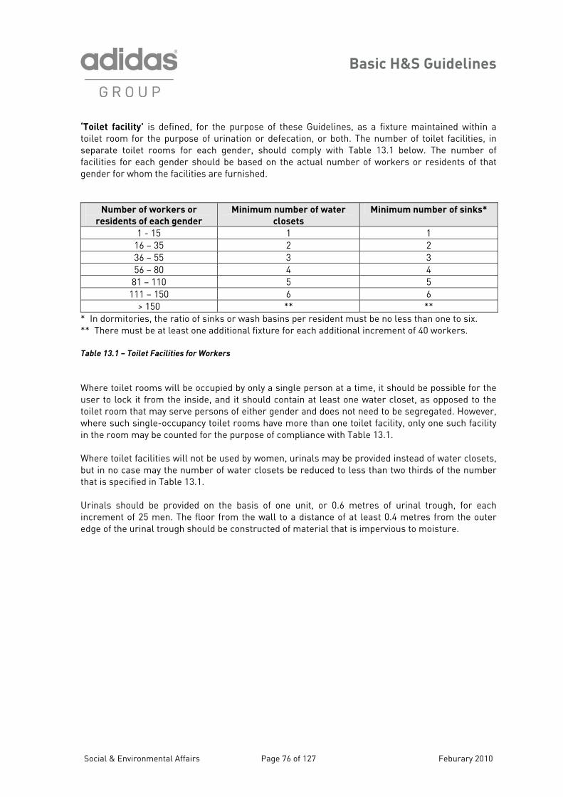
Basic H&S Guidelines
‘Toilet facility’ is defined, for the purpose of these Guidelines, as a fixture maintained within a ilet room for the purpose of urination or defecation, or both. The number of toilet facilities, in
eparate toilet rooms for each gender, should comply with Table 13.1 below. The number of cilities for each gender should be based on the actual number of workers or residents of that
ender for whom the facilities are furnished.
tosfag
Number of workers or
residents of each gender
Minimum number of water
closets
Minimum number of sinks*
1 - 15 1 1 16 – 35 2 2 36 – 55 3 3 56 – 80 4 4
81 – 110 5 5 111 – 150 6 6
> 150 ** ** * In dormitories, the ratio of sinks or wash basins per resident must be no less than one to six. * There must be at least one additional fixture for each additional increment of 40 workers.
able 13.1 – Toilet Facilities for Workers
here toilet rooms will be occupied by only a single person at a time, it should be possible for the ser to lock it from the inside, and it should contain at least one water closet, as opposed to the ilet room that may serve persons of either gender and does not need to be segregated. However, here such single-occupancy toilet rooms have more than one toilet facility, only one such facility the room may be counted for the purpose of compliance with Table 13.1.
here toilet facilities will not be used by women, urinals may be provided instead of water closets, ut in no case may the number of water closets be reduced to less than two thirds of the number at is specified in Table 13.1.
Urinals should be provided on the basis of one unit, or 0.6 metres of urinal trough, for each increment of 25 men. The floor from the wall to a distance of at least 0.4 metres from the outer edge of the urinal trough should be constructed of material that is impervious to moisture.
* T
Wutowin Wbth
Social & Environmental Affairs Page 76 of 127 Feburary 2010
Basic H&S Guidelines
Social & Environmental Affairs Page 77 of 127 Feburary 2010
3.3 Guidelines for Toilet Facilities
he following guidelines relate to the proper practices and precautions that should be taken in anteens, kitchens and other food service areas in factories and dormitories. Factories must omply with all local sanitation regulations and/or the adidas Group Guidelines, whichever is more tringent. It is expected that all worker food service facilities and operations will reflect the ractice of sound hygienic principles. The food that is served should be nutritious, free from poilage, and should be stored, handled, processed and prepared in a manner that would protect it gainst contamination.
1
• Toilet rooms should be marked distinctly “for men” and “for women” by signs printed in the native language of the workers/residents, or marked with easily recognisable symbols or pictures.
• If the toilet rooms for each gender are adjacent spaces, they should be separated by solid walls or partitions that extend from floor to ceiling.
• Toilet rooms must have an opaque window to the outdoors which can be
system. • Each water closet should occupy a
separate compartment with a door and walls, or partitions between the fixtures that are sufficiently high to ensure privacy. There should be no open toilets.
• Urinals should be provided with an adequate water flush. Urinal troughs should drain freely, and the drain construction should be such that it excludes flies and rodents.
• Facilities for the washing of menstrual cloths should be provided in women’s toilet rooms.
• Toilet paper should be provided to the workers/residents.
• Hand-drying facilities (paper towels, clean cloth towels, electric dryer, or other) should be provided in each toilet room.
• Waste bins with tight closable covers should be provided in each toilet stall,
should be located farther than 60m from a toilet room.
• Lighting should be provided for toilet rooms for all hours of day and night. The illumination level should be at least 20 lux (at 0.75m above the floor).
• Each toilet room should be provided with sinks with clean hot and cold (or tepid) running water, either within the room or immediately outside it. The number of sinks should comply with Table 13.1.
• Hand soap or similar cleansing agents should be provided.
• Toilet and shower areas should be cleaned daily with a disinfectant cleaner.
opened for ventilation, and/or they must have an adequate exhaust ventilation
and should be emptied regularly. • In dormitories, no sleeping quarters
Tccspsa
Basic H&S Guidelines
13.4 Guidelines for Kitchens and Canteen Facilities
• Cooked food services should be provided by the factory if the workers have no other reasonable opportunities to obtain cooked food.
• Cold room and freezer refrigeration systems should be operated at the correct recommended temperatures.
• Workers and residents should not be allowed to consume food or beverages in toilet rooms or in any factory area where there may be contact with toxic chemical
The use of hair restraints by kitchen and food service workers is required.
rking and walking surfaces such as false floors, platforms,
dents, insects and other vermin. A continuing and effective extermination programme should be implemented whenever and wherever the presence of vermin is detected.
• Kitchen ventilation systems must be adequate to remove excessive steam, heat, vapours, odours and smoke, and there should be regular proper maintenance of the ventilation ducts.
• A type ABC or type K fire extinguisher
• A properly constructed kitchen and i
ing quarters of
uv ers.
•
i• The kitchen and canteen buildings
cooking, serving, or other handling of food, d h
operates in connection with a dormitory or is used regularly by dormitory residents.
• All kitchen workers should have health certificates from the relevant local authority.
• Sanitary food storage: All food
d ning hall, adequate in size and separated from the sleep
materials. workers, should be provided unless o tside facilities for cooked food are • a ailable for the workDirect openings between living or sleeping quarters of workers and the
• Floors should be maintained as dry aspracticable and constructed with drains
k tchen or dining hall are prohibited. or alternative wo
should provide adequate protection from the weather.
• Seating capacity should be enough for all workers who may be scheduled to eat during any shift.
• No person with any communicable disease should be employed or permitted to work in the preparation,
mats, etc. should be provided where practicable, or water-proof footwear should be used by workers.
• Vermin control: Every kitchen or canteen should be constructed and maintained in such a manner as to prevent the entry and harbourage of ro
foodstuffs, or any materials uset erein, in a kitchen or canteen that
containers should be stored away from the floor, and should not be stored in toilet rooms or in any factory areas where there may be exposure to or contact with toxic chemical materials.
should be available in kitchens for use in the event of a grease or electrical fire (type K is specific for cooking oil fires). Some kitchen workers should be trained in its use.
Social & Environmental Affairs Page 78 of 127 Feburary 2010
Basic H&S Guidelines
Factories and their kitchen staff must recognise that there is a distinction between the cleaning and sanitising of food preparation equipment, utensils and tableware, and that both cleaning and sanitising are necessary for the maintenance of sanitary conditions in kitchens and canteen
cilities. Cleaning involves the removal of food and other residue from the equipment, utensils and bleware, whereas sanitising achieves the elimination of potentially harmful micro-organisms
h leaning: if food or residue has not been emoved from a surface, the surface will not be sanitised.
e of 43°C (110°F).
hemical sanitising methods represent the other common alternative methods. The instructions of
fatafrom t e same materials. Sanitising is not a substitute for cr If manual cleaning of equipment, utensils or tableware is conducted, then a detergent solution should be used and a minimum water temperatur There are a number of methods by which sanitising may be performed. Heat sanitising can be done manually, in a dishwasher or other equipment. A temperature of at least 74°C (165°F) is required for the heat sanitising process to be effective. Cthe manufacturer should be followed with regard to the necessary concentration of the active chemical ingredient, the water temperature, and other parameters. Chlorine, iodine and quarternary ammonium compounds are three common chemical sanitising agents.
Social & Environmental Affairs Page 79 of 127 Feburary 2010
Health and Safety Guidelines - Technical Application
Social & Environmental Affairs Page 80 of 127 February 2010
Technical Application
Section 14 – Material Storage Areas and Ladder Safety This section of the H&S Guidelines applies to warehouses and other locations of material storage other than chemical storage areas. The activities in these storage areas may create a number of risks to the workers, such as:
• Slips and falls, including falls from heights • Cuts and amputations • Crushing injury from material handling, falling objects, or vehicle operation • Air quality issues related to vehicle operation • Electrical hazards • Thermal burns • and/or intense physical activity • harging ve chemicals
h gular occupants, they do face similar fire
be clearly marked unobstructed aisles and gress routes, and appropriate signs for exits. Rubbish and other waste materials should be isposed of regularly and not permitted to accumulate in the aisles. Likewise, containers or stacks f materials should not be permitted to remain in the aisles. Appropriate types of fire extinguishers hould be mounted near the exit doors from storage areas. These precautions assume greater ignificance here because some of the occupants may not be regularly employed in the storage reas, and may not be familiar with the evacuation plan.
4.1 Material Storage Guidelines
The storage practices in these areas should re ct the factory’s concern for worker safety. All shelves and racks should be secured properly to permanent structures in the storage area. This factor assumes greater importance if forklift trucks are in use, since shelves and racks can be
mage hem as a result of a collision. Goods and materials hould be stacked with the heavier items on bottom shelves, and should not exceed the specified ad capacity of the shelves or racks. Pallets should be used for materials that will be stacked or
retrieved by forklift. Workers should avoid climbing on the shelves and racks to place or remove materials. In addition to safe storage practices, the factory may determine that the use of one or more types of personal protective equipment (PPE) is warranted in its storage areas. Such PPE may include impact-resistant safety shoes, hard hats and gloves to protect against cuts and abrasions. If workers must be on a walking or working surface that has unprotected sides or edges and is six feet (~1.8 metres) or more above the floor or lower working surface, then they must be protected from falling. Adequate fall protection systems may consist of guardrails, safety nets, warning line systems, or safety monitor systems. Personal fall protection, such as a securely attached body harness, may also be appropriate.
Musculoskeletal injury from repeated, awkwardBattery c hazards – electrical and corrosi
While t ese storage areas often do not have many resafety issues as other factory locations. There should edossa 1
• Different materials should be stored separately by type.
• The width of a main route in a warehouse should be no less than 2 metres.
• The distance between every two stacks should be no less than 1 metre.
• Stacks need to be at least 0.5 m away from walls.
fle
da d or items can be displaced from tslo
Social & Environmental Affairs Page 81 of 127 Feburary 2010
Technical Application
Recommendation: Use of free-standing mobile platform steps is preferable to the use of ladders in warehouses and material storage areas, if the aisle widths are sufficient to accommodate this equipment. 14.2 Lifting and Manual Handling of Materials Of necessity, these storage areas involve workers in a variety of material handling operations. Workers should be instructed on the proper approach to lifting and manual handling of materials to minimise any stress, strain or injury. Lower back injuries comprise a relatively high percentage of all work-related injuries and represent a significant source of pain to the affected workers and significant cost to the factories. Lower back injuries often result from the lifting, reaching, twisting and bending activities that are required of workers in the performance of their jobs. To reduce the prevalence of such back injuries, efforts should be directed at both the workers and the tasks. The factory should provide training and related assistance to workers whose jobs require these activities on a regular basis. It is recommended that every significant lifting or material handling task be evaluated by a qualified person on the factory staff to determine if there is another way to accomplish the same objective. Before and during a lifting ac vity or other type of
om relevant ergonomic tips:
4.3 An Ergonomic Approach to Lifting
Note: Further information on material storage and handling can be found in the adidas Group’s
Assessing Ergonomic Hazards Guidance Note.
14.4 Use of Forklift Trucks in Storage Areas Forklift trucks are common in larger storage areas where there is sufficient room for their operation. While forklifts reduce the need for otherwise difficult manual handling of materials, they are also a major cause of accidents and injuries in warehouse environments. Proper training of all forklift truck operators is essential to their safe operation. Diesel or gasoline-powered forklift trucks can emit air contaminants such as carbon monoxide and particulates to which workers may be exposed. Generally, propane-fuelled or electric equipment is the preferable alternative.
timanual handling of materials, workers should follow s e 1
• Consider alternative ways to accomplish the same lifting or handling. • Assess the weight of the object before attempting lifting or handling. • Ask for assistance if necessary. • Determine the best way to hold or manoeuvre the object before lifting the object. • During repetitive lifting activities, try to minimise the vertical distance of the lift from origin
to destination, and minimise the amount of twisting and bending. • Use the legs for lifting rather than the back. • Use the feet to turn, rather than twisting the trunk of the body.
Social & Environmental Affairs Page 82 of 127 Feburary 2010
Technical Application
14.5 Guidelines for the Safe Operation of Forklift Trucks
R s should gainst falling objects, and seat belts or other re
1
Ladders are a commonly used piece of e ivities both in material storage areas and in other factory loca n and metal ladders should be i ly for damage or d c be removed from service until the completion of any necessary repairs. The s include the following:
a ehould be no broken steps
• Steps or rungs must be in good c ep and the side rails must be tight in wooden ladders, d ructed of
ises the risk of suld be availa secure when opened
• Any frayed or badly worn rope sh l ders • All moving parts should operate freely
e in good conditi• Metal ladders should have side rails aterial where the worker or
ed parts
• All traffic routes should be marked
well-positioned mirrors or audible alarms.
• Forklift trucks should have warning reverse
travel.
• Forklift trucks should not be overloaded
fe distance from storage of combustible materials.
clearly (and should be one-way only if possible) and kept free of obstructions.
• Surfaces of the traffic routes should be smooth and even.
• The routes should avoid sharp bends and blind corners. Where necessary, use
with materials. • Forklift trucks should not be used to lift
workers so they can perform activities at heights.
• Battery charging areas for electric forklift trucks should be located at a sa
lights and audible signals for
ecommendation: Forklift truck be equipped with rollover protection, protection astraints for the operator.
4.6 Ladder Safety
quipment in a variety of worker acttio s. All portable wooden
nspected regular efe ts and should in pections should
• Ladders should be free from sh• There s
rp dges and splinters , rungs or side rails ondition – the joint between the st an the rungs of metal ladders should be const
lipping material that minim• A locking device sho ble for step ladders so that they are
ou d be replaced on extension lad
• Safety feet should b on made of non-conductive m
the ladder might contact electrically energis
Social & Environmental Affairs Page 83 of 127 Feburary 2010
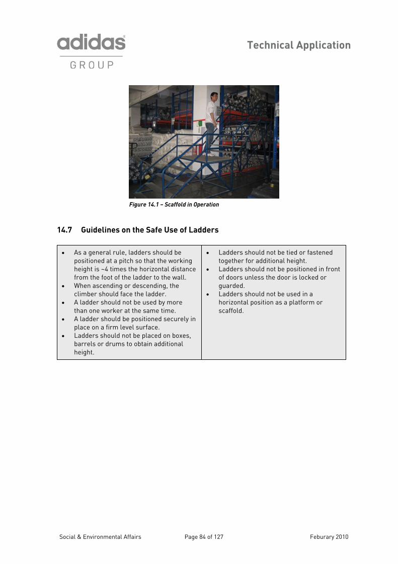
Technical Application
Figure 14.1 – Scaffold in Operation 14.7 Guidelines on the Safe Use of Ladders
• As a general rule, lpositioned at a pitch so that the working
• A ladder should not be used by more than one worker at the same time.
n place on a firm level surface.
• Ladders should not be placed on boxes, barrels or drums to obtain additional height.
adders should be • Ladders should not be tied or fastened together for additional height.
dders should not be used in a horizontal position as a platform or scaffold.
height is ~4 times the horizontal distance from the foot of the ladder to the wall.
• When ascending or descending, the climber should face the ladder.
• Ladders should not be positioned in front of doors unless the door is locked or guarded.
• La
• A ladder should be positioned securely i
Social & Environmental Affairs Page 84 of 127 Feburary 2010
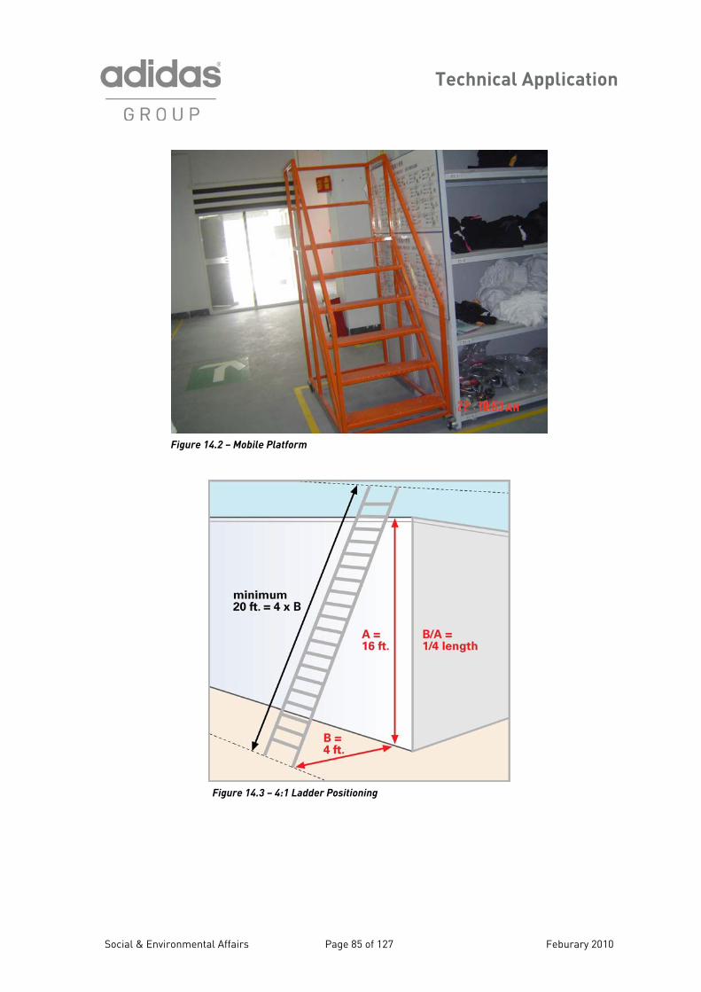
Technical Application
Figure 14.2 – Mobile Platform
Figure 14.3 – 4:1 Ladder Positioning
Social & Environmental Affairs Page 85 of 127 Feburary 2010

Technical Application
Section 15 – Contractor Safety
The acti n introduce many hazards to the factory, some of which may be q e operations. The factory and the
hile complying with all applicable local and national regulations.
vities of outside contractors cauit different from the hazards arising from typical production
contractor must communicate effectively before the contractor begins work to ensure the safety of both the factory workers and the contractor’s workers. As a preliminary requirement, the factory should verify that the contractor’s personnel are qualified to perform the intended work in a safe and professional manner, w
Possible Contractor Activity
Related Hazards or Safety Issues
Trenching or excavation work
• Possible confined space issues • Engulfment and physical hazards – shoring and
sloping issues • Damage to underground utilities, tanks, etc.
Work n electrical systems, steam • Lockout/Tagout issues • Uncontrolled release of
osystems, or other energised equipment
electrical or mechanical energy and risk of physical injury to workers
• Disruption of production
Work at heights • Scaffold safety issues • Ladder safety • Falling objects
Hot Work (e.g. welding, torch cutting, brazing, etc.)
• Fire and personnel safety issues • Air contaminants and exposure • Ultraviolet radiation hazard
Use of chemical materials
• Possible chemical spills or releases to the environment
• Air contaminants and exposure • Hazardous waste generation
Use of cranes and rigging • Damage to property • Physical injury to workers
Table 15.1 – Relating Contractor’s Work to Safety Hazards
ommunication with any outside contractor who will be conducting work on factory grounds must clude instruction on the reporting of emergencies and the proper evacuation procedures in the
the contractor work should take into consideration potential safety and health risks to factory workers in the vicinity.
Cinevent of a fire. The scheduling of
isruptions to production and potentiald A brief discussion of the major contractor activities and the precautions that should be taken by the factory is presented below.
Social & Environmental Affairs Page 86 of 127 Feburary 2010
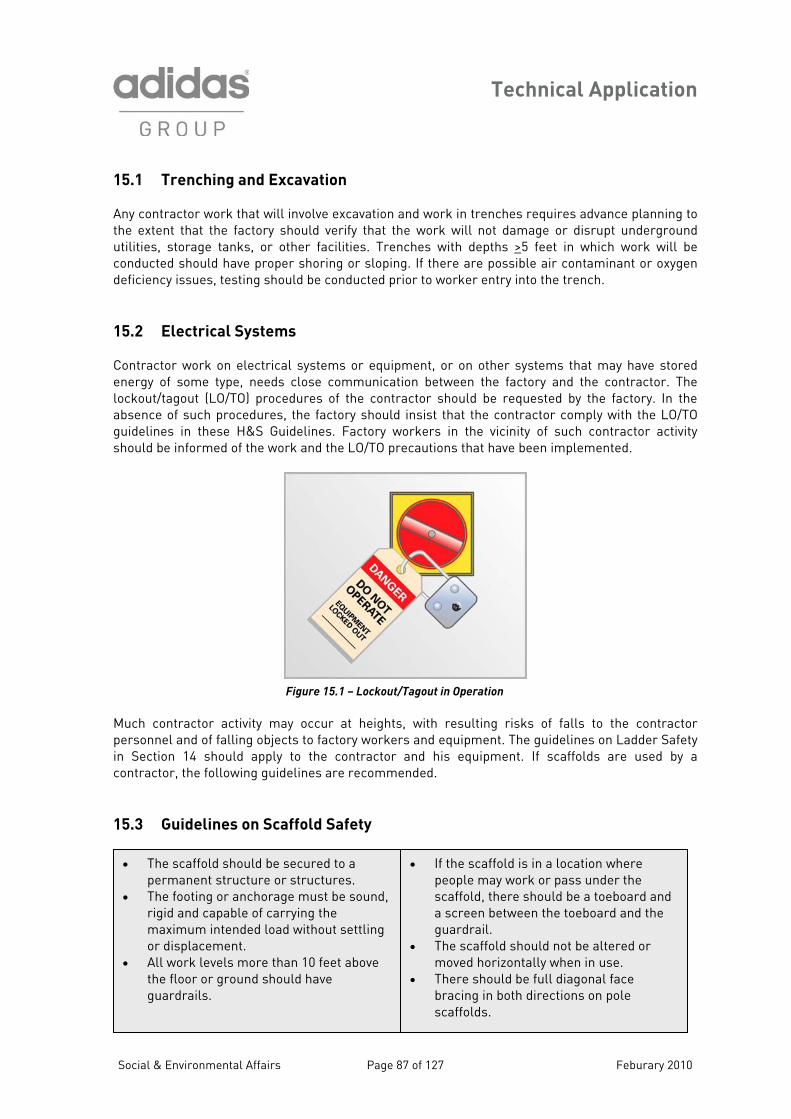
Technical Application
15.1 Trenching and Excavation
fy that the work will not damage or disrupt underground tilities, storage tanks, or other facilities. Trenches with depths >
Any contractor work that will involve excavation and work in trenches requires advance planning to the extent that the factory should veriu 5 feet in which work will be conducted or oxygen deficiency issues, testing should be conducted pr r to worker entry into the trench.
5.2 Electrical Systems
should have proper shoring or sloping. If there are possible air contaminantio
1 Contractor work on electrical systems or equipment, or on other systems that may have stored energy of some type, needs close communication between the factory and the contractor. The lockout/tagout (LO/TO) procedures of the contractor should be requested by the factory. In the absence of such procedures, the factory should insist that the contractor comply with the LO/TO guidelines in these H&S Guidelines. Factory workers in the vicinity of such contractor activity should be informed of the work and the LO/TO precautions that have been implemented.
Figure 15.1 – Lockout/Tagout in Operation
Much contractor activity may occur at heights, with resulting risks of falls to the contractor personnel and of falling objects to factory workers and equipment. The guidelines on Ladder Safety in Section 14 should apply to the contractor and his equipment. If scaffolds are used by a contractor, the following guidelines are recommended. 15.3 Guidelines on Scaffold Safety
• The scaffold should be secured to a • If the sc affold is in a location where people may work or pass under the scaffold, there should be a toeboard and
permanent structure or structures.
• The footing or anchorage must be sound, rigid and capable of carrying the a screen between the toeboard and the
guardrail. • The scaffold should not be altered or
moved h se. • Th ace
bracing in both on pole
maximum intended load without settling or displacement.
• t above ave
guardrails.
orizontally when in uere should be full diagonal f
directions scaffolds.
All work levels more than 10 feethe floor or ground should h
Social & Environmental Affairs Page 87 of 127 Feburary 2010
Technical Application
15.4 Hot Work Hot Work performed by contractors may r w rk is performed, and fire extc ck thei w s of combustib le ch i factory working hours, the work should be should be instituted for a period of 30-60 minut the hot work to ensure the absence of a work-related fire. 1 ng Chemical materials that are used by co a as those used in factory production. The f o SDSs) f l materials that will be brought on site by the contractor, so that any unusual h terials can b rials t release of an ey should ensure that there i ventilation in the work area to minimise the risk of chemical exposures to their own personnel and to factory workers. Any chemical wastes that are generated in the course of the c rk should be removed fro h T of cranes and rigging by contract y p k of damage to factory equipment and risk of physical injury to factory workers. All c e qualified to operate such equipment. The factory should request t ific e ip work to minimise the likelihood o
c eate a significant fire risk. The factory should be awareinguishing equipment should be made available to the hen such wo
ontractor’s personnel if they lale materials or flammab
r o n. The work should be performed away from storeem cals. If welding is conducted in production areas during
enclosed in fire-resistant welding curtains. A fire watches at the conclusion of
5.5 Chemical Handli
ntr ctors are likely to present the same range of hazardsact ry should request Material Safety Data Sheets (M
or all chemicaazards or highly toxic ma e identified. Contractors should have appropriate mate
y chemical that they use. Tho contain and clean a spill ors sufficient
ontractor wo m t e factory grounds by the contractor.
ors in the movement of equipment or materials mahe use resent a risontractor personnel should bhe inspection records for the specf an accident.
qu ment to be used for the
Social & Environmental Affairs Page 88 of 127 Feburary 2010
Technical Application
Section 16 – Personal Protective Equipment (PPE) Requirements Throughout the H&S Guidelines, requirements or recommen ations appear for the provision of and u nal protective equipm t (PPE). In the hierarchy of exposure control m as the “last resort”. Therefore, wherever feasible, c rst. However, in certain situations the use of PPE is the o e the likelihood of worker exposure to a particular h A s should be considered by actories in th sions to provide PPE to a p eve eff ive protection:
or the hazard faced by the workers e PPE must fit the workers
ecessary
T hese factors is perhaps the most significant: the appropriate choice of PPE. While it is obvious that eye protection should be worn to avoid hazard to the eyes, and gloves should be worn t re is a fu ther level of detail with regard to PPE selection t 1 G s the most common type of PPE that is sed in factories, and they are worn to
rotect against a wide range of chemical, mechanical (physical) and thermal hazards. Yet a articular type of glove will not offer protection against every type of hazard. The following uidelines are offered on the issue of glove selection:
6.2 Guidelines on the Selection of Protective Gloves
dse by the workers of perso enethods, PPE should be viewed by the factories
hoose other types of control methods finly reasonable approach to prevent or reducazard.
t least three factor f eir deciarticular group of workers in order to achi
1. The type of PPE must be appropriate f2. Th
ect
3. The PPE must be replaced as n
he first of ts
o protect against injury to the hands, thehat must be considered.
r
6.1 Gloves
loves are perhap uppg 1
• Gloves that are intended to protect against chemicals must be impervious to the particular chemical or general class of chemical, and generally made from some type of rubber.
• Specific information on glove materials and their ratings as protection against various classes of chemicals is available from the glove manufacturers or on the internet.
• Gloves to be used against thermal hazards must be sufficient to protect against the intensity of exposure.
• Hand protection in cutting areas and in material warehouses must be suitable for the particular physical risk (cutting, shearing, puncture, etc.)
• Plain cotton gloves are not useful against als, since they will absorb
against the in.
• Rubber-coated cotton gloves (i.e. rubber
als that does not involve immersion of the hands into liquid.
liquid chemicthe chemical and then hold it worker’s sk
on the fingers and palm) are acceptable for work with chemic
Social & Environmental Affairs Page 89 of 127 Feburary 2010
Technical Application
1 For a proper selection of hearing protection, some explanation of the Noise Reduction Rating (NRR) is necessary because of the inconsistent and likely confusing use of decibel weighting s rical rating in decibels of the protection, or attenuation, of sound that is p ors (HP) under ideal circumstances of use. It usually appears on the packaging of the hearing protection devices. The NRR determination is based on methods developed by the US EPA, and the NRR values are decibels on the C-weighting scale (dBC). Most sound level measurements and worker exposure data from factories are in decibels on t T exposure that will result in the ideal use of a particular hearing protection device, and to verify that this exposure will be less than the limits that are specified in Table 11.1, the following calculation is performed:
Exposure with HP (dBA) = Exposure without HP (dBA) – [NRR (dBC) – 7 dB]
In the equation above, the amount of attenuation provided by the device is [NRR – 7 dB], which obviously is less than the NRR value that is printed on the packaging. A arises in the evaluation of h ot ction is related to the second factor that is listed above: the PPE must fit the worker. The attenuation calculated from the NRR value is t tion that can be obtained by workers if the protective device fits their ears well and is worn properly. However, research has shown that the actual reduction in worker noise e posure is often less than what is calculated from the NRR: for ear plugs, it may be as little as half e with ear muffs on average it is ~75%, or (0.75 x [NRR – 7 dB]). T suggests the import nce of proper training for workers who are e hearing protection. 16.4 Respiratory Protection
S of hearing protection, the effective use of respiratory protection, e.g. dust masks o es, also depends to a large extent on the fit of the e sks, or masks that are not worn properly by workers, may p hazard. The improper fit of other types of PPE may have conseque ces that go beyond the degree of p r. Ill itting PPE is less likely to be accepted and worn b of the workers and/or the quality of their work, and, in e s that did not exist previously (e.g. poorly fitting safety shoes could lead to trip/fall hazards). F ful lifetimes, like other types of equipment or clothing, and P n a regular basis. For example, protective gloves that have tears or holes in the material should be replaced as soon as possible. Hearing protectors may accumulate sweat, chemical residues, dirt and grease, and also need to be replaced regularly to prevent ear infections o artridges that are used in tight-fitting rubber respirators: t re chemicals and should be replaced before saturation o emical exposures, i.e. when a chemical exposure exceeds its TLV or the cumulative chemical exposure (EF value) exceeds 1.0, these cartridges must be replaced daily in order to provide effective removal of the airborne chemicals.
6.3 Hearing Protection
cales. The NRR is a numerovided by various types of hearing protect
he A-weighting scale (dBA).
o estimate the worker
second issue that earing pr e
he maximum protec
x, or (0.5 x [NRR – 7 dB]), whil
his research information axpected to wear
imilar to the use r rubber masks with air-purifying cartridgquipment to the worker. Ill-fitting marovide little or no protection from the airborne
nrotection that the PPE provides to the workey the workers, can impact the productivity xtreme cases, may create new hazard
-f
inally, all types of PPE have finite usePE must be replaced o
r irritation. A final example is the chese have a limited capacity to captuccurs. For hazardous ch
Social & Environmental Affairs Page 90 of 127 Feburary 2010
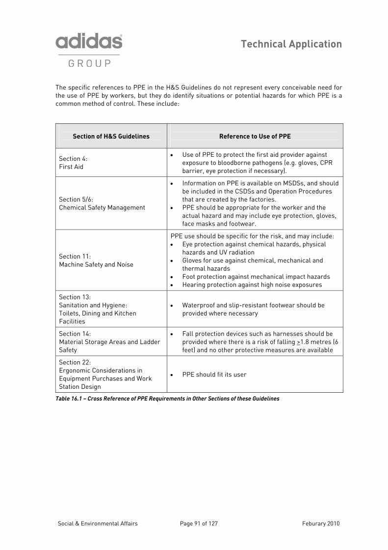
Technical Application
T delines do not represent every conceivable need for t fy situations or potential hazards for which PPE is a c
he specific references to PPE in the H&S Guihe use of PPE by workers, but they do identiommon method of control. These include:
Section of H&S Guidelines
Reference to Use of PPE
Section 4: First Aid
• Use of PPE to protect the first aid provider against exposure to bloodborne pathogens (e.g. gloves, CPR barrier, eye protection if necessary).
Section 5/6: Chemical Safety Management • PP
acface ma
• Information on PPE is available on MSDSs, and should be included in the CSDSs and Operation Procedures that are created by the factories.
E s ld be appropriate for the worker and the tual hazard and may include eye protection, gloves,
sks and footwear.
hou
SMachine S
ection 11: afety and Noise
PPE use should be specific for the risk, and may include: • Eye protection against chemical hazards, physical
hazards and UV radiation • Gloves for use against chemical, mechanical and
thermal hazards • Foot protection against mechanical impact hazards • Hearing protection against high noise exposures
Section 13: Sanitation and Hygiene: Toilets, Dining and Kitchen
• Waterproof and slip-resistant footwear should be provided where n cessary e
Facilities
Section 14:
Safety
• Fall protection devices such as harnesses should be sk of falling >Material Storage Areas and Ladder provided where there is a ri 1.8 metres (6
feet) and no other protective measures are available
Section 22: Ergonomic Considerations in Equipment Purchases and Work Station Design
• PPE should fit its user
Table 16.1 – Cross Reference of PPE Requirements in Other Sections of these Guidelines
Social & Environmental Affairs Page 91 of 127 Feburary 2010
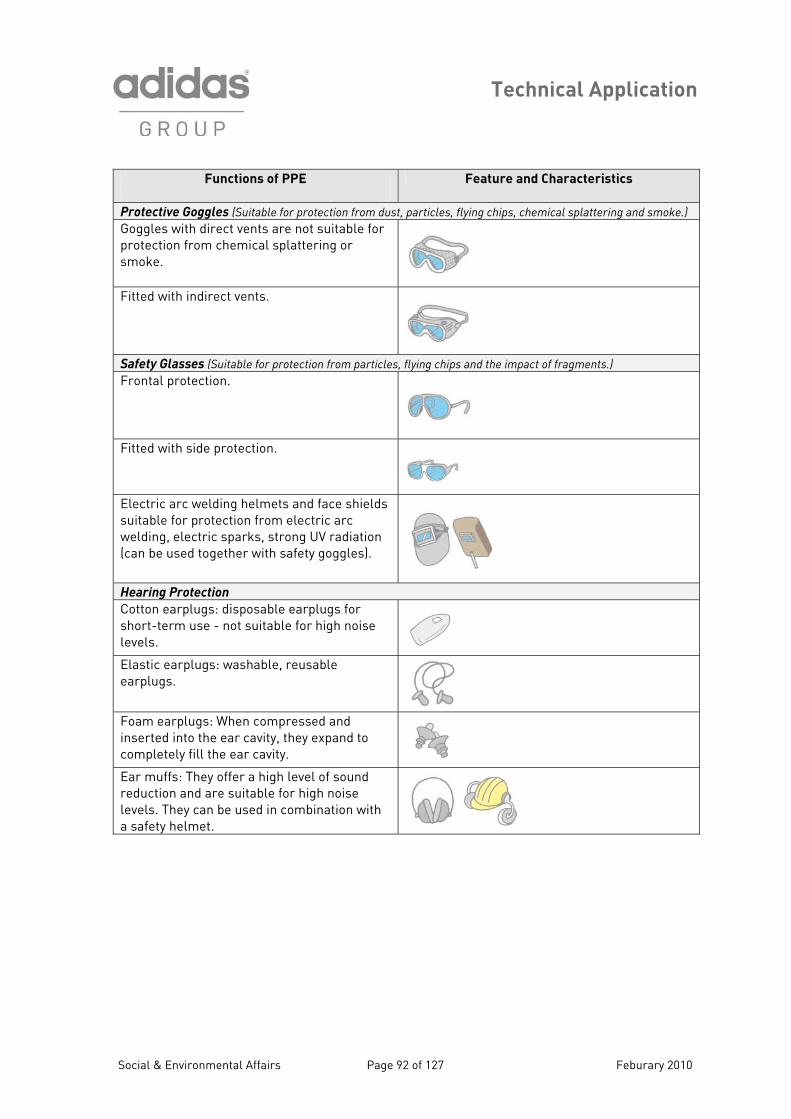
Technical Application
Functions of PPE
Feat re and Characteristics u
Protective Goggles (Suitable fo r rticles, flying chips, chemical splattering and smoke.) r p otection from dust, pa
Goggles with direct vents ar oprotection from chemical splattesmoke.
e n t suitable for ring or
Fitted with indirect vents.
Safety Glasses (Suitable for pro t .) tec ion from particles, flying chips and the impact of fragments
Frontal protection.
Fitted with side protection.
Electric arc welding helmets andsuitable for protection from elec
ectric sparks, strong UV radiation r with s t
face shields tric arc
welding, el(can be used togethe afe y goggles).
Hearing Protection
Cotton earplugs: disposablese - not suitable for
earplugs for high noise short-term u
levels.
Elastic earplugs: washable, reusearplugs.
able
Foam e en compressed and inserted into the ear cavity, they expand to
ill the ear cavity
arplugs: Wh
completely f .
Ear muffs: They offer a highd are suitable for high noise
in c b
level of sound reduction anlevels. They can be useda safety helmet.
om ination with
Social & Environmental Affairs Page 92 of 127 Feburary 2010
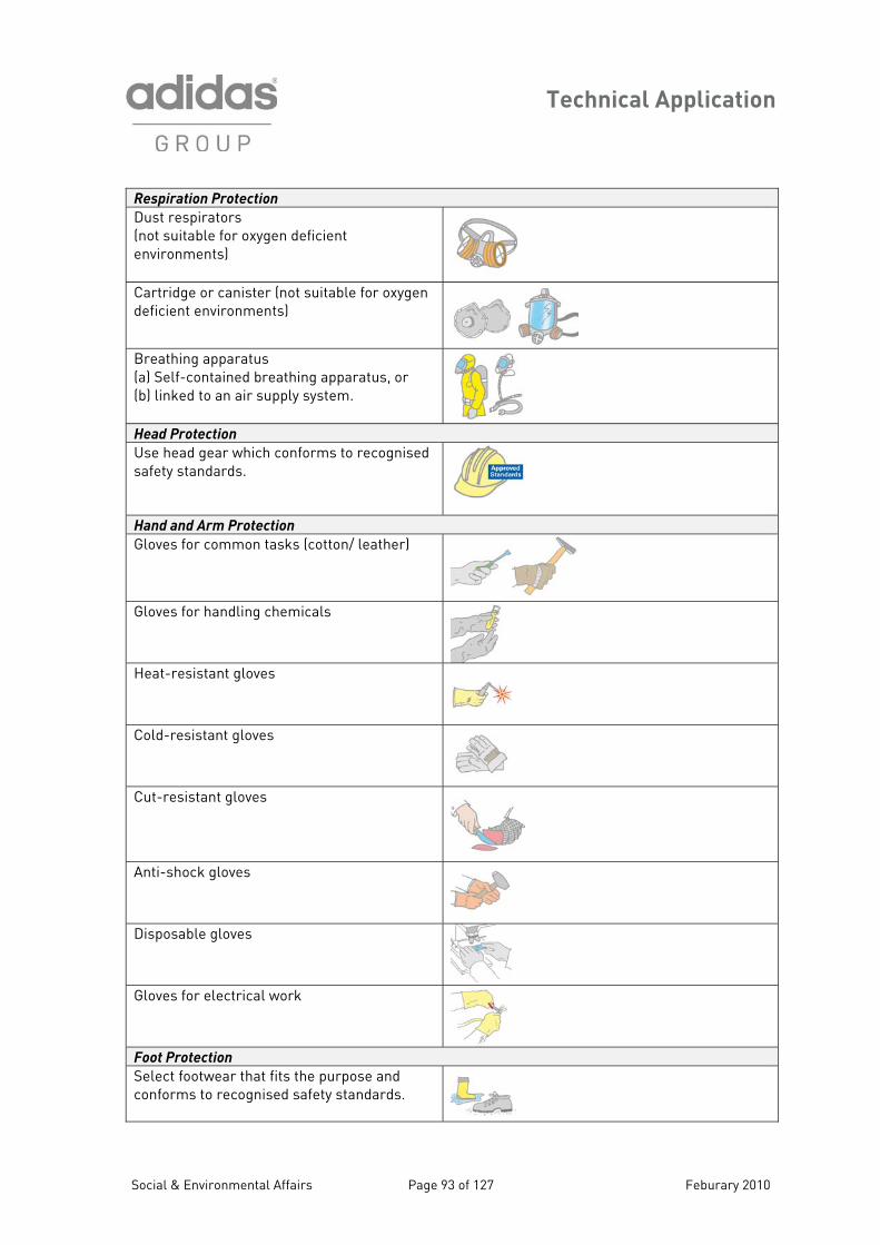
Technical Application
Respiration Protection
Dust respirators (not suitable for oxygen deficient
s)
environment
Cartridge or canister deficient environme
(not suitablnts)
e for oxygen
Breathing apparatus (a) Self-contained breathing apparatus, or (b) linked to an air supply system. Head Protection
Use head gear which conforms to recognised safety standards.
Hand and Arm Protection
Gloves for common tasks (cotton/ leather)
Gloves for handling chemicals
Heat-resistant gloves
Cold-resistant gloves
Cut-resistant gloves
Anti-shock gloves
Disposable gloves
Gloves for electrical work
Foot Protection
Select footwear that fits the purpose and orms to recognised safety standards. conf
Social & Environmental Affairs Page 93 of 127 Feburary 2010
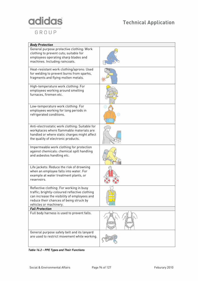
Technical Application
Body Protection
General purpose protective clothing: Work clothing to prevent cuts; suitable for employees operating sharp blades and machines. Including raincoats.
Heat-resistant work clothing/aprons: Used
efragments and flying molten metals. for w lding to prevent burns from sparks,
High-temperature work clothing: For employees working around smelting furnaces, firemen etc.
Low-temperature work clothing: For employees working for long periods in
refrigerated conditions.
Anti-electrostatic work clothing: Suitable for aces where flammable materials are
cts.
workplhandled or where static charges might affect the quality of electronic produ
Impermeable work clothing fagainst chemicals: chemical
or protection spill handling
and asbestos handling etc.
Life jackets: Reduce the risk of drowning when an employee falls into water. For example at water treatment plants, or
reservoirs.
Reflective clothing: For working in busy traffic; brightly-coloured reflectivcan increase the visibility of employees and re nces of be
e
e clothing
duce their cha ing struck by vehicles or machin ry. Fall Protection
Full body harness is use o
d t prevent falls.
General purpose safety t are used to restrict
bel and its lanyardmovement while working.
Table 16.2 – PPE Types a
nd Their Functions
Social & Environmental Affairs Page 94 of 127 Feburary 2010
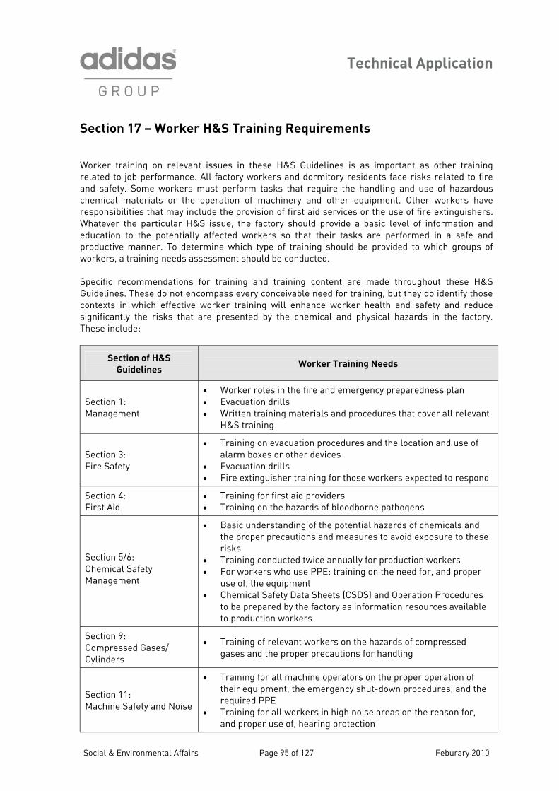
Technical Application
Section 17 – Worker H&S Training Requirements Worker training on rele t es in these H&S Guidelines is as important as other training related to job performan A nd dormitory residents face risks related to fire and safety. Some worke m t require the handling and use of hazardous chemical materials or t s have responsibilities that may incl rovision of first aid services or the use of fire extinguishers. Whatever the particu el of information and education to the potenti y orkers so that their tasks are performed in a safe and productive manner. To d r ich type of training should be provided to which groups of workers, a training needs ss nducted. S atio f nd training content are made throughout these H&S Guidelines. These do not c ble need for training, but they do identify those contexts in which effective w l enhance worker health and safety and reduce significantly the risks th a e chemical and physical hazards in the factory. These include:
van issuce. ll factory workers ars ust perform tasks thahe operation of machinery and other equipment. Other worker
ude the plar H&S issue, the factory should provide a basic lev
all affected wete mine wh a essment should be co
pecific recommend ns or training aen ompass every conceiva
orker training wily that re presented b
Section of H&S
Guidelines
Worker Training Needs
Section 1: Management
oles in the fire and emergency preparedness plan uation drills ten training materials and procedures that cover all relevant
• Worker r• Evac• Writ
H&S training
Section 3: • Tra
alarFire Safety
ining on evacuation procedures and the location and use of m boxes or other devices
• Evacuation drills • Fire extinguisher training for those workers expected to respond
Section 4: First Aid
• Trainin• Trainin
g for first aid providers g on the hazards of bloodborne pathogens
Section 5/6:
• Basic understanding of the potential hazards of chemicals and the proper precautions and measures to avoid exposure to these risks
Chemical Safety Management
• For workers who use PPE: training on the need for, and proper use
• Training conducted twice annually for production workers
of, the equipment • Chemical Safety Data Sheets (CSDS) and Operation Procedures
to be prepared by the factory as information resources available to production workers
Section 9: Compressed Gases/ Cylinders
gases and the proper precautions for handling • Training of relevant workers on the hazards of compressed
Section 11: Machine Safety and
• Training for all machine operators on the proper operation of their equipment, the emergency shut-down procedures, and the
PE • Training for all workers i on the reason for,
oper use of, hearin
Noise required P
n high noise areasg protection and pr
Social & Environmental Affairs Page 95 of 127 Feburary 2010
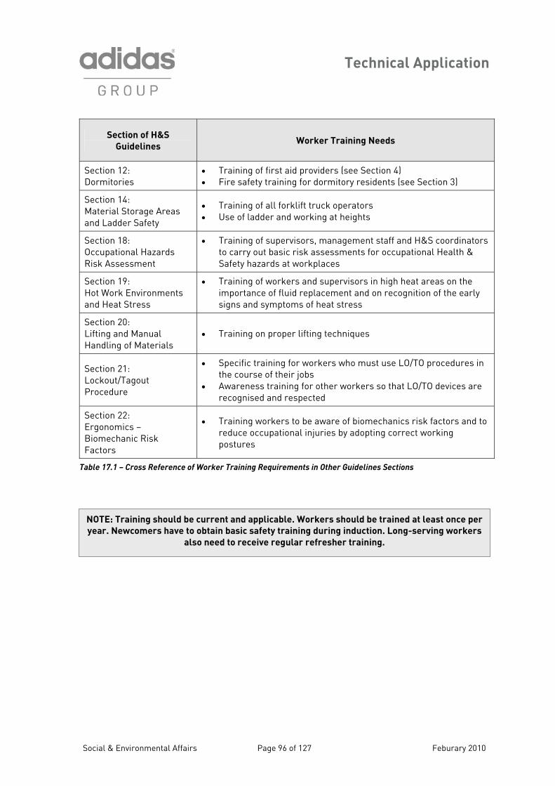
Technical Application
Section of H&S
Guidelines Worker Training Needs
Section 12: Dormitories
• Training of first Fire safety training for
aid providers (see Section 4) • dormitory residents (see Section 3)
Section 14Ma Stand Ladder Safety
• Use of ladder and working at heights
: terial orage Areas
• Training of all forklift truck operators
Section 18: Occu tional Hazards
• Training of supervisorsto carry out basic risk apa
, management staff and H&S coordinators ssessments for occupational Health &
Risk Assessment Safety hazards at workplaces
Section 19: Hot Work Environments and Heat Stress
• Training of workers and supervisors in high heat areas on the importance of fluid replacement and on recognition of the early signs and symptoms of heat stress
Section 20: Lifting and Manual Handling of Materials
• Training on proper lifting techniques
Section 21:
d
• Specific training for workers who must use LO/TO procedures in the course of their jobs Awareness training for other workers so that LO/TO devices are recognised and respected
Lockout/Tagout Proce ure
•
Section 22: Ergonomics –
• Training workers to be aware of biomechanics risk factors and to reduce occupational injuries by adopting correct workin
Biomechanic Risk g
Factors postures
Table 17.1 – Cross Reference of Worker Training Requirements in Other Guidelines Sections
NOTE: Training should be current and applicable. Workers should be trained at least once per
year. Newcomers have to obtain basic safety training during induction. Long-serving workers
also need to receive regular refresher training.
Social & Environmental Affairs Page 96 of 127 Feburary 2010
Technical Application
Section 18 – Occupational Hazards Risk Assessment 18.1 What is Risk Assessment?
isk assessment is nothing more than a careful examination of what could cause harm to people in enough precautions or whether you should
rt or becomes ill. Ill health and accidents can ruin lives nd also affect your business if production is lost, property or machinery damaged because of
them. Hazard
A hazard is anything that has otenti example chemicals, electricity, working at height, etc.). Risk
A risk is the likelihood (great or small) of harm be g done.
factory inimise the associated risk. It is important that you check this aspect when you
ssess the risks. For example, electricity can kill but the risk of it doing so in an office environment components are insulated and metal casings are properly
arthed (grounded).
8.2 How Do You Conduct a Risk Assessment?
is important that you do not overcomplicate the task. In most industries the hazards are few and simple. m is mainly a matter of common sense y necessary. You may have already as vents. For other hazards yo , or if there
ard e ay tha an accident. If so, ch taken what reasonable precau ns you can to avoid injury. 18.3 Risk Assessment Steps Step 1: Look for the hazards
Step 2: Decide who might be harmed and how Step 3: Evaluate the risks Step 4: Record your findings Step 5: New safety measures
Ryour workplace. It allows you to decide if you have taken take more. The idea is to make sure that no one gets hua
the p al to cause harm (for
in What you need to decide is whether a hazard is significant, and whether you have taken satisprecautions to mais remote, provided that the “live”e 1 It
Checking the , but even so it is versessed some of them, for example the use of toxic chemicals and sol
u probably already know if you have machinery that could cause harmis an awkw ntrance or stairw t may cause eck that you have
tio
Social & Environmental Affairs Page 97 of 127 Feburary 2010
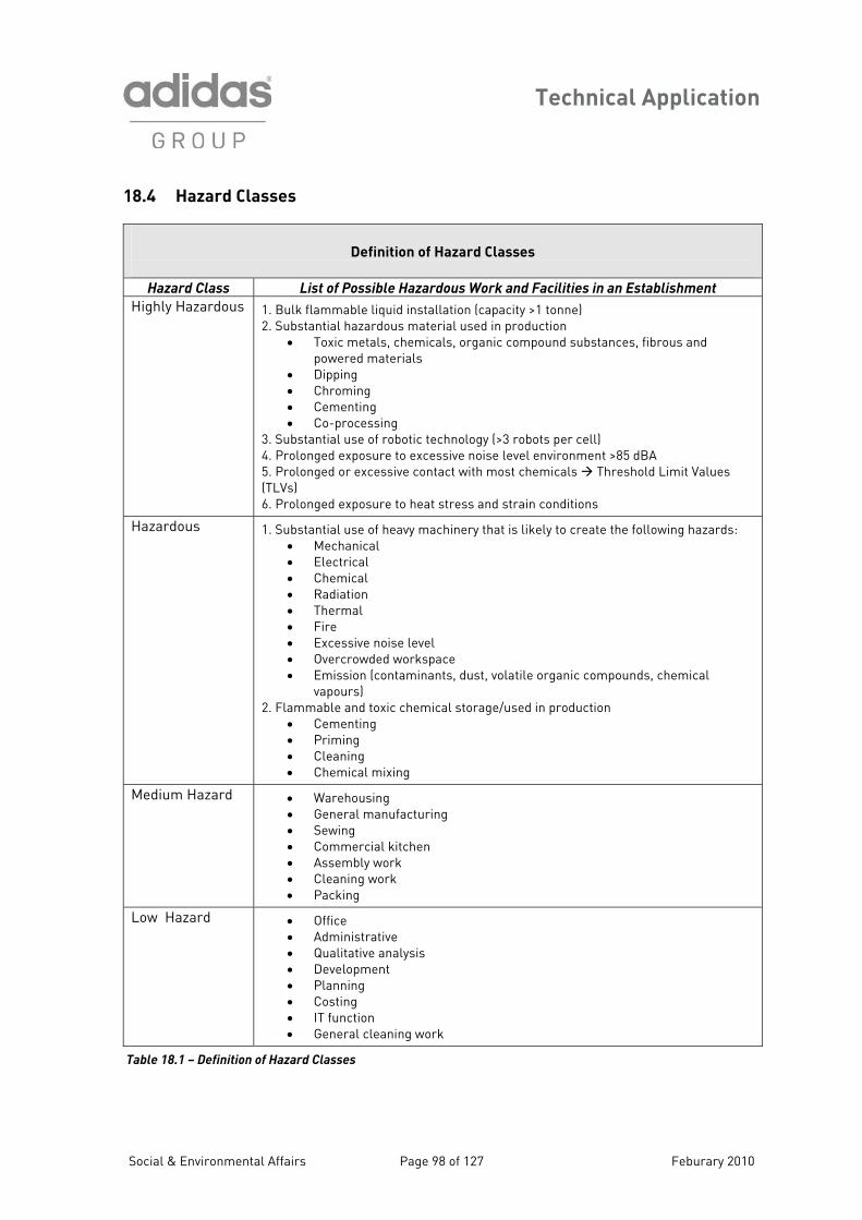
Technical Application
18.4 Hazard Classes
Definition of Hazard Classes
Hazard Class List of Possible Hazardous Work and Facilities in an Establishment
Highly Hazardous 1. Bulk flammable liqui tion (capacintial haza ed in prToxic met gan copowered materials
• Dipping • Chroming • Cementing • Co-processing
3. Substantial use of robotic technology (4. Prolonged exposure to excessive nois 5. Prolonged or excessive contact with m(TLVs)
ged expo an
d installa ty >1 tonne) 2. Substa
• rdous material usals, chemicals, or
oduction ic mpound substances, fibrous and
>3 robots per cell) e level environment >85 dBAost chemicals Threshold Limit Values
d strain conditions 6. Prolon sure to heat stress
Hazardous 1. Substantial use of heavy machinery th• Mechanical • Electrical • Chemical Radiation
• Excessive noise level
2. Flammable and toxic chemical storage/used in production • Cementing
ning
at is likely to create the following hazards:
•• Thermal • Fire
• Overcrowded workspace • Emission (contaminants, dust, volatile organic compounds, chemical
vapours)
• Priming • Clea• Chemical mixing
Medium Hazard using l manufacturing
• Sewing cial kitchen
• Assembly work
• Wareho• Genera
• Commer
• Cleaning work g • Packin
Low ard Haz • Office
g • Costing • IT function • General cleaning work
• Administrative • Qualitative analysis • Development • Plannin
Tab 8
le 1 .1 – Definition of Hazard Classes
Social & Environmental Affairs Page 98 of 127 Feburary 2010
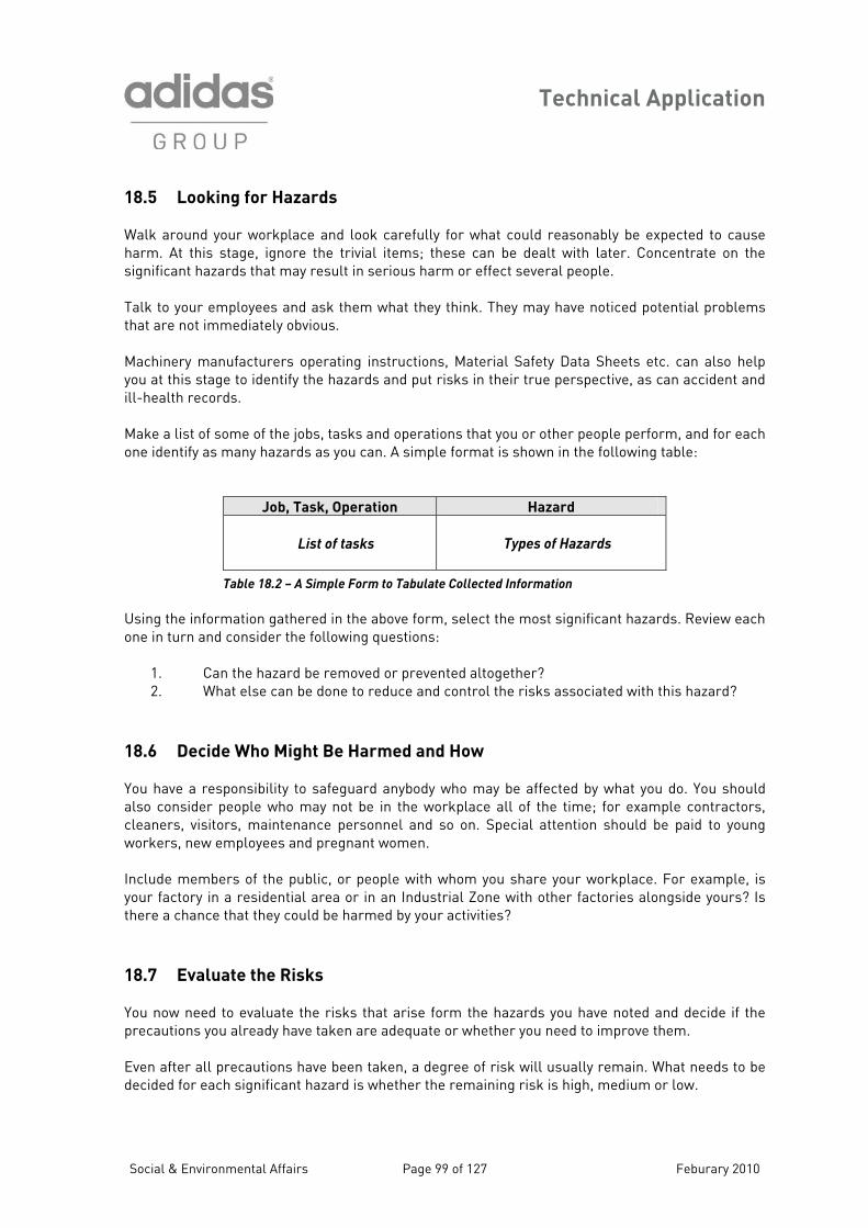
Technical Application
18.5 Looking for Hazards
for what could reasonably be expected to cause arm. At this stage, ignore the trivial items; these can be dealt with later. Concentrate on the
sign a n serious harm or effect several people. Talk s that are s.
n also help ou at this stage to identify the hazards and put risks in their true perspective, as can accident and
ill-h lt
ake a list of some of the jobs, tasks and operations that you or other people perform, and for each
Walk around your workplace and look carefully h
ific nt hazards that may result i
to your employees and ask them what they think. They may have noticed potential problem not immediately obviou
Machinery manufacturers operating instructions, Material Safety Data Sheets etc. cay
ea h records.
Mone identify as many hazards as you can. A simple format is shown in the following table:
Job, Task, Operation Hazard
List of tasks
Types of Hazards
lected Information
sin h above form, select the most significant hazards. Review each
ssociated with this hazard?
18. You v y be affected by what you do. You should also on r example contractors, clea r g workers
clude members of the public, or people with whom you share your workplace. For example, is in an Industrial Zone with other factories alongside yours? Is rmed by your activities?
ou now need to evaluate the risks that arise form the hazards you have noted and decide if the
ions have been taken, a degree of risk will usually remain. What needs to be dec d e remaining risk is high, medium or low.
Table 18.2 – A Simple Form to Tabulate Col
Uo
g t e information gathered in thene in turn and consider the following questions:
1. Can the hazard be removed or prevented altogether? 2. What else can be done to reduce and control the risks a
6 Decide Who Might Be Harmed and How
ha e a responsibility to safeguard anybody who ma c sider people who may not be in the workplace all of the time; fone s, visitors, maintenance personnel and so on. Special attention should be paid to youn
, new employees and pregnant women. Inyour factory in a residential area orthere a chance that they could be ha
18.7 Evaluate the Risks Yprecautions you already have taken are adequate or whether you need to improve them. Even after all precaut
ide for each significant hazard is whether th
Social & Environmental Affairs Page 99 of 127 Feburary 2010
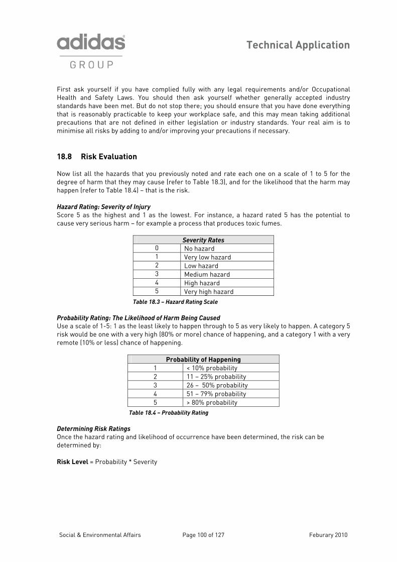
Technical Application
Social & Environmental Affairs Page 100 of 127 Feburary 2010
ty Laws. You should then ask yourself whether generally accepted industry tandards have been met. But do not stop there; you should ensure that you have done everything
.
he egree of harm that they may cause (refer to Table 18.3), and for the likelihood that the harm may
s the potential to ause very serious harm – for example a process that produces toxic fumes.
First ask yourself if you have complied fully with any legal requirements and/or Occupational Health and Safesthat is reasonably practicable to keep your workplace safe, and this may mean taking additional precautions that are not defined in either legislation or industry standards. Your real aim is to minimise all risks by adding to and/or improving your precautions if necessary 18.8 Risk Evaluation Now list all the hazards that you previously noted and rate each one on a scale of 1 to 5 for tdhappen (refer to Table 18.4) – that is the risk. Hazard Rating: Severity of Injury
Score 5 as the highest and 1 as the lowest. For instance, a hazard rated 5 hac
Severity Rates
0 No hazard 1 Very low hazard 2 Low hazard 3 Medium hazard 4 High hazard 5 Very high hazard
Table 18.3 – Hazard Rating Scale
Probability Rating: The Likelihood of Harm Being Caused
scale of 1-5: 1 as the least likely to happen through to 5 as very likely to happen. A category 5 risk wou % or more) chance of happening, and a category 1 with a very rem e ing.
Use ald be one with a very high (80
ot (10% or less) chance of happen
Probability of Happening
1 < 10% probability 2 11 – 25% probability 3 26 – 50% probability 4 51 – 79% probability 5 > 80% probability
Table 18.4 – Probability Rating
etermining Risk Ratings D
Once the hazard rating and likelihood of occurrence have been determined, the risk can be mined by:
= Probability * Severity
deter Risk Level
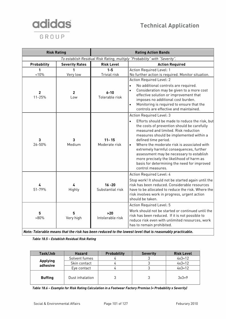
Technical Application
Social & Environmental Affairs Page 101 of 127 Feburary 2010
Risk Rating R ng ion ati Act Bands
To establish Residual Ris ating, multiply “Probability” with “Severity”. k R
Probability Severity Rates sk Level Acti red Ri on Requi
1
<10% 1
Very low 1-5 Action Required L
No further action onitor situation. Trivial risk evelis re
: 1 quired. M
2
11-25% 2
Low
Action Required L
• No additional contr are required. • Consideration m given to a more cost
ctiv olu provement that burden.
• Monitoring is ensure that the controls are effective and maintained.
6-10
Tolerable risk
evel
ation or
required to
: 2
olsy be
imeffeimposes no additional cost
e s
3
26-50% 3
Moderate risk
Action Required L
• Efforts should b e tothe costs of p n sh be carefully measured and duction measures sho pl ted within a defined time period.
• Where the mo ciated with extremely harmful q r assessment may to establish more precise lih of harm as basis for determining the ne r improved control meas
Medium 11- 15
evel
e revent
limited. Risuld
derate risk is asso
ly th
ures.
: 3
madio
be im
consebe necese like
reduce the risk, butouldk re
emen
uences, furthesary
ood ed fo
4
51-79% 4
Highly Substantia
Action Required L
Stop work! It should again until the risk has been redu ble resources have to be allocate du risk. Where the
16 -20
l risk
evel
nced. Cod to
: 4
ot b
re
e startednside
cera
the risk involves work gent action should be taken.
in progress, ur
5
>80% 5
I
Action Required L
Work should not b ed until the possible to sources, work
has to remain prohibited.
Very high >20
erablentol risk
evel
e started or
: 5
If it is unli
continunot
erisk reduc
has been reduced. e risk even with mited r
Note: Tolerable means ha du to lowest level that is reasonably pthat the risk s been re ced the racticable.
Table 18.5 – l Risk Rating
Establish Residua
Task/Job Hazard Probability Severity Risk Level
Solvent fumes 4 3 4x3=12 Skin contact 4 3 4x3=12
Ap g
adhesive 3
plyin
Eye contact 4 4x3=12
Buffing Dust inhalation 3 3 3x3=9
Table 18.6 – lat Footwear y Pr Probability x S Example for Risk Rating Calcu ion in a Factor emise (= everity)
Technical Application
Social & Environmental Affairs Page 102 of 127 Feburary 2010
18.9 Record Your Findings Just completin ses nt is only pa f the operati n; you should record your findings, conclusions an mm ns. A sugg d format for a ssessment is given at the end of this section es. Use this app
1. Write d n th2. Record rta or exa le:
Solv mb t ventil ded and regular heck Or: al i and earth ound to be in good
condition.
You should form e ur findings. There o ed t sho w your assess ovid
• A prope• Yo h• You taking into account the number of pe
who Assessmen to be and sufficient, not perfect. The critica s
• Are t a onabl• Is t me ow t p check was made?
You should writte nts fo or reference; if you are questioned ns you have en. Such docume to check on sp show u have complied wit To make thin lw other documents, such
• Manua• Yo licy ents • Comp• Manufactur
These may and There is n to you whethe hem separate. By maintain s :
• Show asonable actions to reduce the risks to workers • Maintain details endations/actions taken to reduc risks • Use previous ent results when re-assessing tas s • Develop r tasks • Re ting and/or recomm• De gulatory authorities, om et that e risk arising
from yo ve been assessed opriate actions taken
g the asd reco
ow your
ctric
nnt, pr
r check was ked walt wit
ed
prec so
ep ut the ic issu
simpler,
ls alth an
les er
y listombin
records
hat you ar
gene ef
rate ur operat
smeendatio
delin
ost signio
se
lation
our em that you
madeight beobviou
itable
reaso sh
docume
nd help
can a
fety po
struction
zards all the d
f risk a
akineco
assessessmeness o
loyions ha
rt oeste
zards. ons – f
cal exhaus
ions
ut yo:
hazards,
o risk a
of the H&S
roach:
ent fumes
Ele
also ime
u as decould be involved.
ts ne
he here
ke aboecif
gs
ur heany ru
alreadr you c
ing
t
view themonst
Gui
e mmost imp from as
nstal
yed
o mh the
su
utionsthing t
n precautioes a
you
d sa
s’ in
hae
o
e tof r
risk ric asfectivto emp
ficant hant cly
s: wiring, insulat
ploy ca
. affes signif
onclusi line: lo
es abon show
cted. icant
mpation provi ly c ed.
checked and f
is n ne o w ho you did
ople
l que
n also remind requir
as:
peat a
stion
em
ll the
are:
er you
ents.
se, and it
e? hat a
r future use
that
ays ref
arrang
cautuments
ment
roper
tak yo
er to
em
ions. or keep t
s you ca
this can help latnts ca
h legal
to re
keep a
is up
s
preoc
sess
o need
n
g remmsm
ents forf exis
ees, re
ek
controls ers,
similaended
cust c. th s and appr
Technical Application
18.10 New Safety Measures Improving health and safety in your factory does not necessarily mean spendi arge amounts of money. Covering slippery steps with non-slip material, or placing a mirror o dangerous blind corner to help prevent vehicle accidents are inexpensive precautions when yo onsider the risks that these hazards cause. You should also consider training, m e safety n es, reviewing and changin orking practices. If you find that you need to take a s to imp the health and safety in r workplace you should ask yourself:
• Can I eliminate the hazard altogether? • If not, how can I control the s so that harm is unlikely?
You should only resort to the use there is thing else you c easonably do to reduce the risk. If the work done in the workplace es greatly, select zards w h can reasonably foresee and where you can assess t arising from t o tice any unusual hazard, collect information about it and take whatever act ne s 18.11 Review Your Assessment Once complet your asse ould be revi gularly, and revised if necessary. There may be e heal n fety laws or i best practices th ould require you to change you igina sessm t y you y all new machine r new processes that could lea new zards. If th is any signific nge, you should a t to your original assessment t e in ccoun e w hazards and cautions required However, it is o go ractice to ularly review your essments. You d t ne to amend them for eve ivia minor ch e or for each new or task, but if new b or task introduces sig hazards ts , you should r them in th own ht and do whatever you d to imise the . 18.12 Health & Sa y Risk A ss nt Form C c t An example o p alth fety Risk Asses n rm s n abl .7 below. You may find g p you int questions u w h ings hich must all be covered o detail
• Comp dres• Depar s ion assess• Date ssess• Next r• What s• Who m • What are i• What further o eds t ta ?
ng ln a u c
g w you
an r
you u no
at wry odd i.
o nothe eir
in Tead
orction
risk
of PPE when
varihe risks
ent sh
d sa. Alternativelere ne
regangof i
risk
sse
and Sar po.
s ed or’s
n plo be
oticrove
no
thoshemions
d re
try inst
chapre
ass job con
he
smende
e ha. After that,are
hic if y
ary. ces
ed,
changr ord too tak
alsry trnificantnee
f a cit he, ide
anytme
of aseview date haz
ighsafe
risk
s inl as hato a
od pl or new min
fet
letel to in s
ectsme
exi at reas
acti
ssm
th aen
t th
ewe
ndus maant the
ed jo
rig
e 18, w
own
me
side
klis
t for the f
is ollo
omlpfually
name annt/ses
ardst bety m
d Heroume
d ad
nt, a
t? isk?uresn ne
howing s or
me
? ken
na
ace
Social & Environmental Affairs Page 103 of 127 Feburary 2010

Technical Application
Risk assessments may also be done in the context of the environment. Releegarding conducting Environmental Risk Assessments can be found in the
vant information adidas Group
nvironmental Guidelines.
rE
Social & Environmental Affairs Page 104 of 127 Feburary 2010
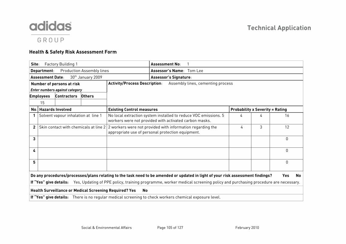
Technical Application
isk
ing
Health & Saf
Site: Factor
Social & Environmental Affairs Page 105 of 127 February 2010
ety R smen orm
y Build A 1
A
1
sses t F
ssessment No:
Department: Prod mbly A uction Asse lines ssessor’s Name: Tom Lee
Assessment Date: y 200 A ur 30th Januar 9 ssessor’s Signat e:
Number of persons at risk Enter numbers against category
Employees Contra rs ctors Othe
15
Activity/P ri y l ting cess rocess Desc ption: Assembl ines, cemen pro
No. Hazards Involve Existing C ur Probab everity = Ratingd ontrol meas es ility x S
1 Solvent va
pour i line No local e te u sionsworkers w ided ca
4 4 1nhalation at 1 xtraction sysere not prov
m installed to redwith activated
ce VOC emisrbon masks.
. 5 6
2 Skin cont
act wit at lin 2 workers ovide io the appropriat sona ip
4 3 1h chemicals e 2 were not pre use of per
d with informatl protection equ
n regarding ment.
2
3 0
4 0
5 0
Do any procedures/ e lans r ing to the t be a dated f your risk assessm ndings? Yes No proc sses/p elat ask need to mended or up in light o ent fi
If “Yes” give details: Ye ting E policy, t ram dical g policy and purchasi edure are necessary. s, Upda of PP raining prog me, worker me screenin ng proc
Health Surveillance or Me cree Required dical S ning ? Yes No
If “Yes” give details: There is o reg medical sc heck ical level. n ular reening to c workers chem exposure
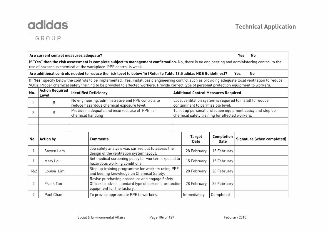
Technical Application
easur
Social & Environmental Affairs Page 106 of 127 Feburary 2010
Are c m es quat Yes No urrent control ade e?
If “Ye k m is co te subject to management confirmation. No, there is no engineering and administering con e use o e t t orkp PPE control is weak.
s”
f hathe
zan t
rdohe
us ris
chassess
mical aent
he wmple
lace.trol to th
Are a ntrol ded redu e risk level to below 16 (Refer to Table 18.5 adidas H&S Guidelines)? Yes No dditional co s nee to ce th
If “Ye low ntrols to be emented. Yes, install basic engineering control such as providing adequate local ventilatio e VOCs er emica y training t provided to affected workers. Provide correct type of personal protection equipment to wor
s” . Pr
speop
cify be ch
the col safet
implo be
n to reduckers.
No. Required
tified Defi Additional Control Measures Required
Ac
Le
tion
vel
Iden ciency
1 5 engineering inistrative and PPE controls to
ce hazardo hemical exposure level. Local ventilation system is required to install to reduce contaminant to permissible level.
No redu
, admus c
2 5 ide inad d incorrect use of PPE for
mical handTo set up personal protection equipment policy and stechemical safety training for affected workers.
Provche
equate anling
p up
No. Action by Comments Target Date
Completion Date
Signature (when c ed) omplet
1 Steven Lam Job safety analysis was carried out to assess the design of the ventilation system layout.
28 February 15 February
1 Mary Lou Set medical screening policy for workers exposed to hazardous working conditions.
15 February 15 February
1&2 Louisa Lim Step up training programme for workers using PPE and beefing knowledge on Chemical Safety.
28 February 20 February
2 Frank Tan Revise purchasing procedure and engage Safety Officer to advise standard type of personal protectionequipment for the factory.
28 February 25 February
2 Paul Chan To provide appropriate PPE to workers. Immediately Completed
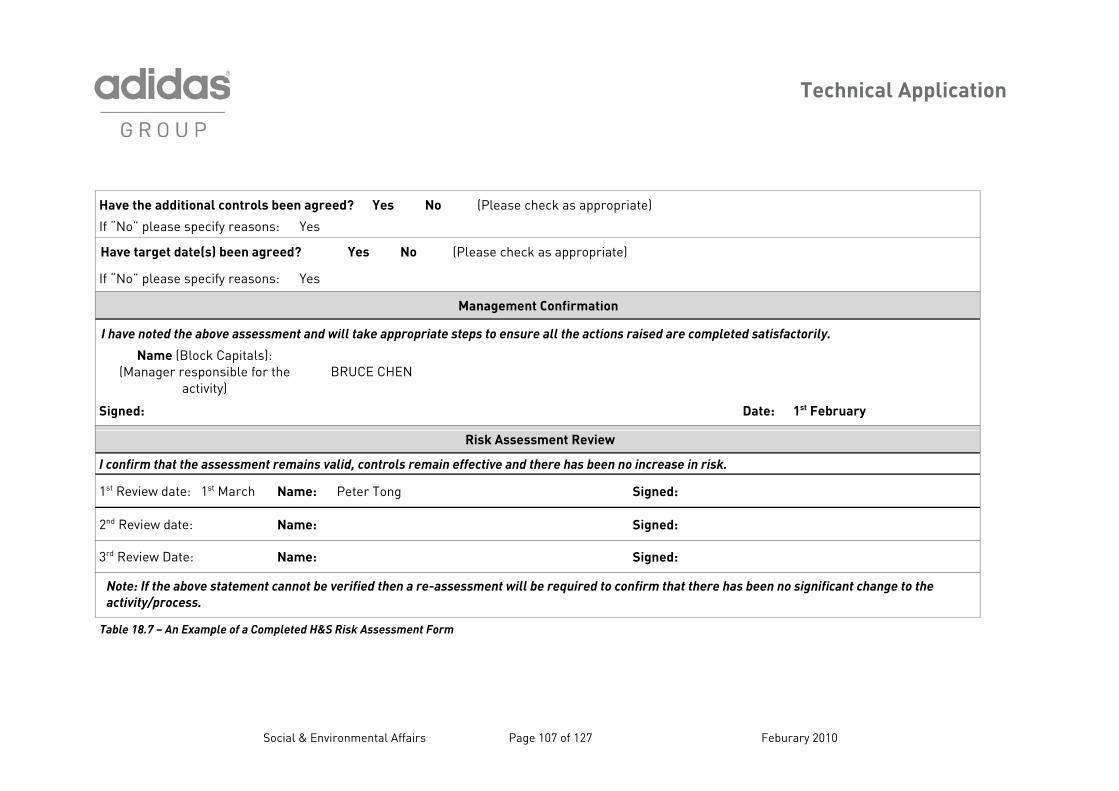
Technical Application
nal contro
Social & Environmental Affairs Page 107 of 127 Feburary 2010
e o l en d Yes o as s ro Have th additi s be agree ? N (Ple e check a app priate)
If “No” p p o lease s ecify reas ns: Yes
Have targe te ag d? (P ch p iat da (s) been ree Yes No lease eck as ap ropr te)
If “No” plea p o se s ecify reas ns: Yes
em ir ioManag ent Conf mat n
note es n ill e e st en h io ed m s a ly. I have d the above ass sme t and w tak appropriat eps to sure all t e act ns rais are co pleted atisf ctori
Nam lo lsnage s o e
ctR E CH
e (Br re
a
ck Capitaponsible fivity)
): r th(Ma B UC EN
Signed: a 1st FebruD te: ary
Risk Asse nt R ewssme evi
I confirm th e en main li ntro in ef an e ha en r riat th assessm t re s va d, co ls rema fective d ther s be no inc ease in sk.
1st Review d : Name: Pe Tong nate 1st March ter Sig ed:
2nd Review d : Name: nate Sig ed:
3rd Review : Name: ned:Date Sig
Note:
activit
If th ove s ent cannot erified the asse will be required to m th er been no signifi he
y/pr s.
e ab
oces
tatem be v n a re- ssment confir at th e has cant change to t
Table 18.7 – xamp Completed H Risk Assess rm An E le of a &S ment Fo
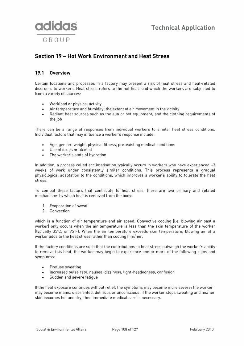
Technical Application
Section 19 – Hot Work Environment and Heat Stress 19.1 Overview Certain locations and processes in a factory may present a
isorders to workers. Heat stress refers to the net heat load risk of heat stress and heat-related which the workers are subjected to
of air movement in the vicinity
of responses from individual workers to similar heat stress conditions.
ced ~3 wee process represents a gradual
lo worker’s ability to tolerate the heat
mary and related
1.
which is perature and air speed. Convective cooling (i.e. blowing air past a wor r)(typicall en the air temperature exceeds skin temperature, blowing air at a worker adds to the heat stress rather than cooling him/her.
eat, the worker may begin to experience one or more of the following signs and ymptoms:
• Profuse sweating
severe fatigue
ating and his/her kin becomes hot and dry, then immediate medical care is necessary.
dfrom a variety of sources:
• Workload or physical activity • Air temperature and humidity; the extent• Radiant heat sources such as the sun or hot equipment, and the clothing requirements of
the job
There can be a range Individual factors that may influence a worker’s response include:
• Age, gender, weight, physical fitness, pre-existing medical conditions • Use of drugs or alcohol • The worker’s state of hydration
In addition, n workers who have experiena process called acclimatisation typically occurs i
ks of work under consistently similar conditions. Thisgical adaptation to the conditions, which improves aphysio
stress. To combat these factors that contribute to heat stress, there are two primechanisms by which heat is removed from the body:
Evaporation of sweat 2. Convection
a function of air temke only occurs when the air temperature is less than the skin temperature of the worker
y 35oC, or 95oF). Wh
If the factory conditions are such that the contributions to heat stress outweigh the worker’s ability to remove this hs
• Increased pulse rate, nausea, dizziness, light-headedness, confusion • Sudden and
If the heat exposure continues without relief, the symptoms may become more severe: the worker may become manic, disoriented, delirious or unconscious. If the worker stops swes
Social & Environmental Affairs Page 108 of 127 February 2010
Technical Application
19.2 Guidelines for Relief of Heat Stress in Workers
• lba
• Sh• In ir velocity past workers if air temperature is <35oC • Sensible clothing for workers • • Co
F uid replacement: provide small volumes of water or other replacement fluid on a regular sis (e.g. 1 cup [~250 milliliters] of fluid every 20 minutes) ielding of radiant heat sources (e.g. hot equipment)
crease a
Rest breaks in a cooler environment and/or job rotation in the hot environment oling vests or other water-cooled garments
Figure 19.1 – Sheltering from Radiant Heat
reasonable approach by factories to the issue of heat exposure to workers and potential heat tress problems should include: (1) the recognition of factory locations where heat exposure may e significant; (2) actions to reduce heat exposure and heat stress of the affected workers and (3)
plementation of basic medical surveillance techniques. The particular heat exposure c plemented dep nd on the particular location, the task and the exposed workers. However, replacemen t has been lost through sweating is always a critical measure. Thirst is a poor guide to rely upon r fluid i ty until dehydration has already occurred. This is why a regular proce l replacement for heat-exposed workers is t void the more seriou evelop in workers. T ervisors. This t ress the importance of regular fluid replacement by workers, the role of workers i e early signs and symptoms of heat stress as a means of avoiding more serious consequences, and the necessity for a reasonable adjustment of work expectations in hot work environ
Asbim
ontrol measures that should be im et of fluid tha
fontake: generally, a worker will not be thirs
ss of f uid essential o as effects that may d
he factory approach should include training of affected workers and their supraining should stn recognising th
ments.
Social & Environmental Affairs Page 109 of 127 Feburary 2010

Technical Application
19.3 Recognition of Heat Stress in Workers: Basic Medical Surveillance Air temperature alone is a poor indicator of the r eat stress in worker it can identify whet onvective coolin ible heat r e workers themselves – their physiological responses and the development signs and symptoms of expo rovide more reliable indicators, and attention should be paid to the workers. Co erature is a good measure of heat ress in workers, but oral tempe i obtained and is usually ~0.5°C less than the core temperature. Pulse ra the workers. Listening to the workers them ify problems at an early stage and help t
• Core body temperature >3• Sustained pulse rate over
8oC (oral temperature >37.5oC) several minutes of [180 – rker age] beats per minute • Recovery pu peak w ats per minute Weight loss during a single work shift of >1 Symptoms of nausea, dizziness, light-headed e fatigue
wolse rate one minute after ork effort of >110 be
• .5% of body weight • ness and/or sever
potential fo h s, althoughher c g may be used as a poss elief measure. Instead, th
of earlysure – p
re body temp strature is more eas ly
tes are convenient measures, but the guidelines above presume normal cardiac health status inselves may ident
o avoid more severe effects.
Social & Environmental Affairs Page 110 of 127 Feburary 2010
Technical Application
Section 20 – Tagout/Lockout Procedure 20.1 The purpose of ermit to Work Syst or all work activities and operations which are required to ta lace on/in:
• Confined work areas
ndling
2
d/or supply of
goods or services, or a complete project or installation. • The contractor ctly responsible for pervision
2 rocedure fo Application
y
o Work System’ Forms (see Fi 20.3 below) om the Sec
nd that must continue to supervis until its completion.
Th adhere in the box provided in Part 1 of the application form.
en and explain:
• The nature of work (description of work) • The expected duration of the work (date and time) • Where
Th o priate box. If Y , t tly the description and tag number of the equipment to be isolated. The co tractor must also clearly stipulate in writing the number of personnel and identification card numbers (to be attache to the permit) of the wor ers under direct supervision of the contra The co additional workers to a valid permit.
Purpose
the implementation of the ‘P em’ is to safely control and monitke p
• Hot work
• Electrical systems • Hazardous chemical ha• Shutdown of fire protection system
0.2 Definitions
• Contractor: An organisation responsible to the factory for the design an f
Supervisor: ’s employee dire the immediate suand control of a group of personnel employed by the contractor.
0.3 P r
Part 1: Application – to be completed by Contractor
When a contractor needs to perform work as specified above, he must obtain the necessar‘Permit t gures 20.1 – fr urity Office.
contractor’s supervisor directly responsible for the work can apply f , aOnly theame pers
or the permits on e the work
e supervisor must declare that all statutory restrictions have been read, understood andd to by placing a tick
The contractor must provide details of the work to be undertak
the work is to be carried out (location)
must determine if an electrical isolation is required and tick the approe cES
ntractorhen the contractor must stipulate exac
nd k
ctor.
ntractor is not permitted to add
Social & Environmental Affairs Page 111 of 127 Feburary 2010
Technical Application
After completion of Part 1, the sub- ontractor’s supervisor must submit the permit to the Facilities Depar ment and ap oval. Part 2 o be complet d by Facilities Engineer
If an electrical isolation is required as declared in the Application, Part 1), the Facilities Engineer must eck and acknowledge the w rk to be done. He must also check and confirm the location of t n d the equipment tag. If no electrical isolation is nec ssary, Part 2 of the form can be struck through and be deemed as N/A (n applicable). An electrical isolation must be carried out by the Facilities Department using approved type padloc to securely lock off the electrical isolator. The padlock keys shall be controlled by Facilities. The equipment concerned must be proven to be ‘ ad’, using appropriate electrical test equipment. T n corded on the permit. Part 2 is compl when it is endorsed by signature. Part 3 risation – to be completed by Facilities Engineer
The F er must check the area, equipment ion carried out for the intended work prior to signing the authorisation. He will also indicate other safety requirements or c dit He must then sign to indicate that he has checked, and is satisfied with, the provision and
or electrical systems
ctment for assess pr
: Endorsement – t e
(ch o
he i tended work, the equipment description an
eot
ks de
he umbers of the padlock(s) used in the isolation must be reeted only
: Autho
acilities Engine and any isolat
on ions for the subcontractor to comply with.
conditions of work. F
f the contractor for the duration of the work and must be handed back to the Facilities
he contractor’s supervisor must ensure that the Permit to Work is clearly displayed either:
• At the entrance door to a controlled access area, or • At the equipment where the work is to be carried out
e completed by Contractor
pon completion of the work, the contractor’s supervisor must ensure that:
that any further work is ‘unsafe’. • All materials and tools have been removed from the worksite and the area has been
cleaned thoroughly. e permit has been thoroughly checked to confirm that it
If applicable, he can hand over a key to the contractor allowing access to the switch room or area that is under the control of the Facilities Department. The care of the key must be the responsibility oDepartment on completion of Part 4. T
Part 4: Notification of Completion – to b
U
• All workers under his authority are made aware that the permit is to be cancelled and that no further work is to take place on that equipment or in that declared area.
• All workers have been made aware
• All equipment isolated as part of this safe to turn on.
Social & Environmental Affairs Page 112 of 127 Feburary 2010
Technical Application
When satisfied that the above conditions have been met, the contractor must return any keys to the Security Office, sign the declaration in Part 4 and return the original copy of the permit to the
ecurity Office.
e intended work.
d that the contractor has fulfilled the obligations in the Notification of Completion, the acilities Department must re-commission the electrical system and sign Part 5.
The ure reference.
• Permits should only be valid for standard project working hours, which are 8.00 am to 6.00 pm, unless it is clearly stated on the permit that extended working hours are required. The Facilities or Maintenance Department should reserve the right to approve such extended hours.
• A contractor’s employees who are not identified on the original permit are not allowed to enter areas or work on equipment under the control of the permit.
• The contractor is not allowed to add new workers’ names to a valid permit.
• The contractor is not allowed to change or deface a valid permit.
• Contractors who are issued a key to a controlled area must be responsible for locking the
door to the controlled area each time they leave. The Facilities Department should not be held liable for any equipment loss, damage or theft w en a controlling key is issued to the
• Contractors who are caught not following the above procedures or deliberately disobeying the stated rules and regulations should have their permit cancelled. Warning: Repeat offenders may be banned from working on site.
S
Part 5: Equipment Re-Commissioning – to be completed by Facilities Engineer
The Facilities Engineer must check the area, equipment and any isolation previously carried out for th When satisfieF
original permit is filed by Security for fut
20.4 Rules and Regulations
hcontractor.
Social & Environmental Affairs Page 113 of 127 Feburary 2010
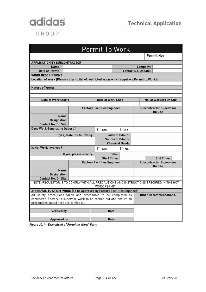
Technical Application
Permit To Work Permit No: APPLICATION BY SUBCONTRACTOR
Name: Company: Date of Permit: Contact No. On Site:
WORK DESCRIPTIONS Location of Work (Please refer to list of restricted areas which require a Permit to Work):
Nature of Work:
Date of Work Starts Date of Work Ends No. of Workers On Site
Factory Facilities Engineer Subcontractor Supervisor
On Site
Name
Designation
Contact No. On Site
Does Work Generating Odours? Yes
No
If yes, state the following: Cause of Odour:
Source of Odour:
Chemical Used:
Is Hot Work involved? Yes No
If yes, please specify: Date:
Start Time: End Time:
Factory Facilities Engineer Subcontractor Supervisor
On Site
Name
Designation
Contact No. On Site
NOTE: REQUESTOR IS TO COMPLY WITH ALL PRECAUTIONS AND INSTRUCTIONS SPECIFIED IN THE HOT WORK PERMIT.
APPROVAL TO START WORK (To be approved by Factory Facilities Engineer)
All safety precautions taken and procedures to be contractor. Factory to supervise work to be carried out
completed by and ensure all
precautions stated here are carried out:
Other Recommendations:
Verified by Date
Approved by Date
Figure 20.1 – Example of a “Permit to Work” Form
Social & Environmental Affairs Page 114 of 127 Feburary 2010
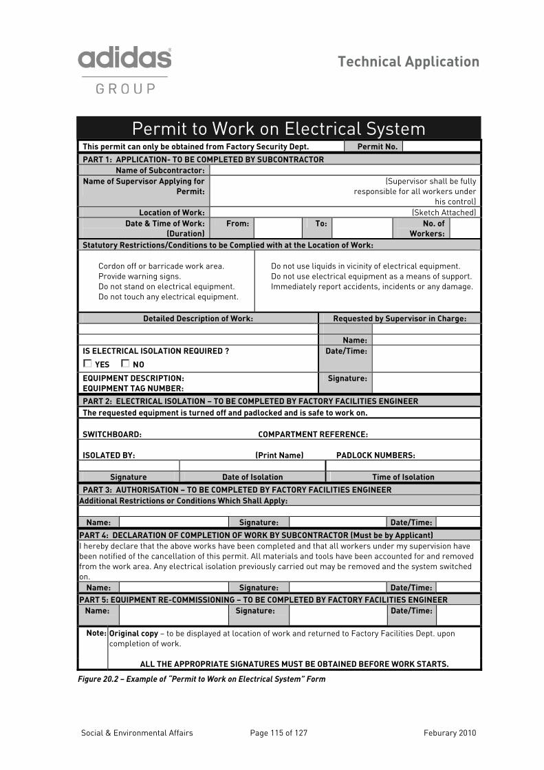
Technical Application
Permit to Work on Electrical System Th eis p rmit can only be obtained from Factory Security Dept. Permit No.
PART 1: APPLICATION- TO BE COMPLETED BY SUBCONTRACTOR
Name of Subcontractor: Na ome f Supervisor Applying for
Permit:
(Supervisor shall be fully responsible for all workers under
his control) Location of Work: (Sketch Attached)
Date & Time of Work:
(Duration)
From: To: No. of
Workers:
Statutory Restrictions/Conditions to be Complied with at the Location of Work:
Cordon off or barricade work area. Provide warning signs.
equipment. Do not touch any electrical equipment.
Do not use liquids in vicinity of electrical equipment. Do not use electrical equipment as a means of support. Immediately report accidents, incidents or any damage. Do not stand on electrical
Detailed Description of Work: Requested by Supervisor in Charge:
Name:
IS ELECTRICAL ISOLATION REQUIRED ?
YES NO
Date/Time:
EQUIPMENT DESCRIPTION:
EQUIPMENT TAG NUMBER:
Signature:
PART 2: ELECTRICAL ISOLATION – TO BE COMPLETED BY FACTORY FACILITIES ENGINEER
The requested equipment is turned off and padlocked and is safe to work on.
SWITCHBOARD: COMPARTMENT REFERENCE:
ISOLATED BY: (Print Name) PADLOCK NUMBERS:
Signature Date of Isolation Time of Isolation
PART 3: AUTHORISATION – TO BE COMPLETED BY FACTORY FACILITIES ENGINEER
Additional Restrictions or Conditions Which Shall Apply:
Name: Signature: Date/Time:
PART 4: DECLARATION OF COMPLETION OF WORK BY SUBCONTRACTOR (Must be by Applicant)
I hereby declare that the above works have been completed and that all workers under my supervision have been notified of the cancellation of this permit. All materials and tools have been accounted for and removed from the work area. Any electrical isolation previously carried out may be removed and the system switched on.
Name: Signature: Date/Time:
PART 5: EQUIPMENT RE-COMMISSIONING – TO BE COMPLETED BY FACTORY FACILITIES ENGINEER
Name:
Signature: Date/Time:
Note: Original copy – to be displayed at location of work and returned to Factory Facilities Dept. upon completion of work.
ALL THE APPROPRIATE SIGNATURES MUST BE OBTAINED BEFORE WORK STARTS.
Figure 20.2 – Example of “Permit to Work on Electrical System” Form
Social & Environmental Affairs Page 115 of 127 Feburary 2010
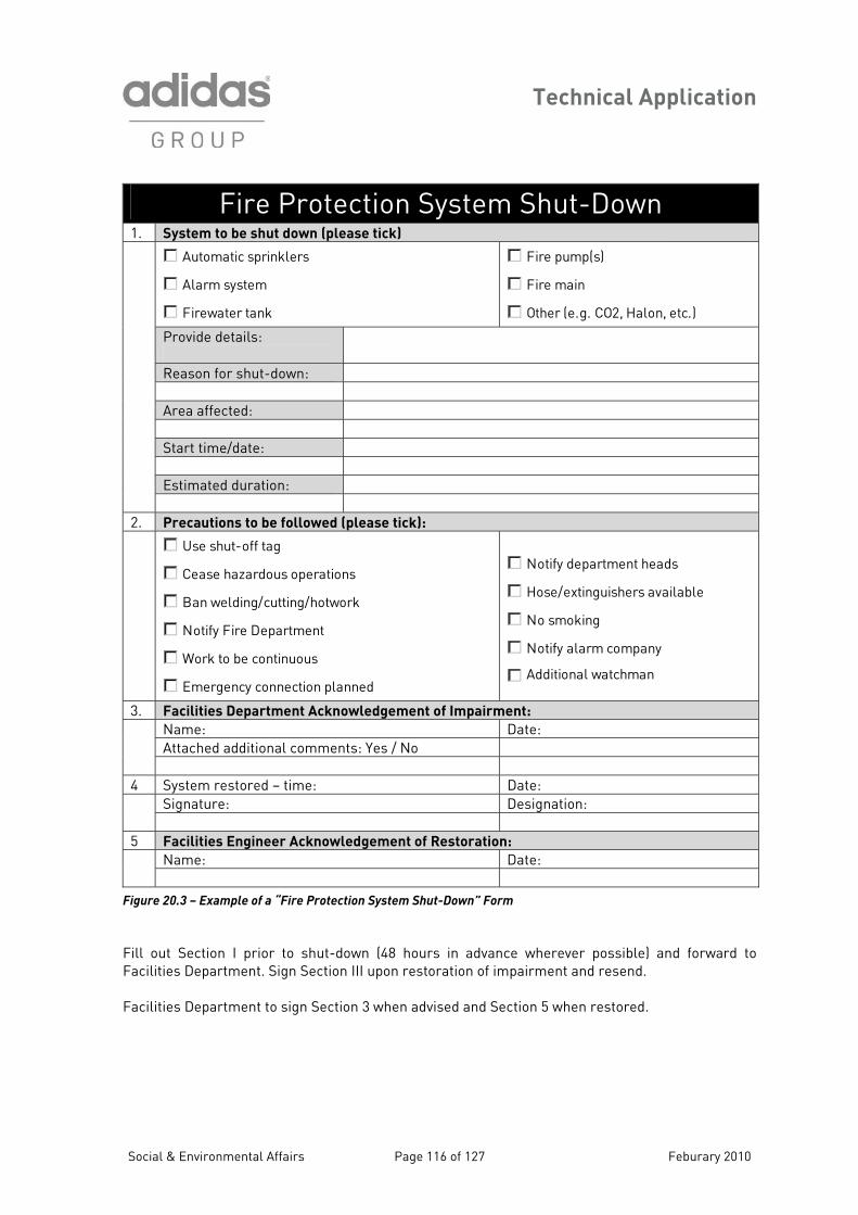
Technical Application
Fire Protection System Shut-Down System to be shut down1. (please tick)
Fire pump(s)
Fire main
Automatic sprinklers
Alarm system
Firewater tank
Other (e.g. CO2, Halon, etc.)
P
rovide details: Reason for shut-down: A rea affected: Start time/date: Estimated duration:
2. Precautions to be followed (please tick):
Use shut-off tag
Cease hazardous operations
Ban welding/cutting/hotwork
Notify Fire Department
Work to be continuous
Emergency connection planned
Notify department heads
Hose/extinguishers available
No smoking
Notify alarm company
Additional watchman ill
3. Facilities Department Acknowledgement of Impairment:
Name: Date: Attached additional comments: Yes / No
4 System restored – time: Date:
Signature: Designation:
5 Facilities Engineer Acknowledgement of Restoration:
Name: Date:
Figure 20.3 – Example of a “Fire Protection System Shut-Down” Form
Fill out Section I prior to shut-down (48 hours in advance wherever possible) and forward to Facilities Department. Sign Section III upon restoration of impairment and resend. Facilities Department to sign Section 3 when advised and Section 5 when restored.
Social & Environmental Affairs Page 116 of 127 Feburary 2010
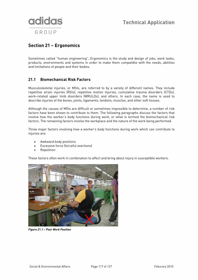
Technical Application
Social & Environmental Affairs Page 117 of 127 Feburary 2010
Section 21 – Ergonomics Sometimes called “human engineering”, Ergonomics is the study and design of jobs, work tasks, products, environments and systems in order to make them compatible with the needs, abilities and limitations of people and their bodies.
21.1 Biomechanical Risk Factors
Musculoskeletal injuries, or MSIs, are referred to by a variety of different names. They include repetitive strain injuries (RSIs), repetitive motion injuries, cumulative trauma disorders (CTDs), work-related upper limb disorders (WRULDs), and others. In each case, the name is used to describe injuries of the bones, joints, ligaments, tendons, muscles, and other soft tissues. Although the causes of MSIs are difficult or sometimes impossible to determine, a number of risk
aragraphs discuss the factors that at is termed the biomechanical risk
ctors. The remaining factors involve the workplace and the nature of the work being performed.
ow a worker’s body functions during work which can contribute to
Thes a
factors have been shown to contribute to them. The following nvolve how the worker’s body functions during work, or wh
pifa
hree major factors involving hTinjuries are:
• Awkward body positions • Excessive force (forceful exertions) • Repetition
e f ctors often work in combination to affect and bring about injury in susceptible workers.
Figure 21.1 – Poor Work Position
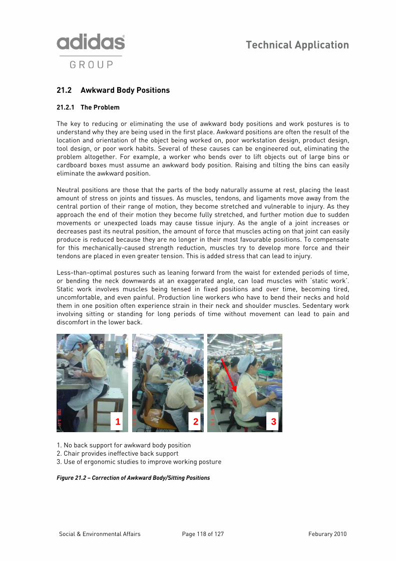
Technical Application
21.2 Awkward Body Positions
ard body positions and work postures is to used in the first place. Awkward positions are often the result of the object being worked on, poor workstation design, product design,
ol design, or poor work habits. Several of these causes can be engineered out, eliminating the
motion due to sudden ovements or unexpected loads may cause tissue injury. As the angle of a joint increases or
ecreases past its neutral position, the amount of force that muscles acting on that joint can easily roduce is reduced because they are no longer in their most favourable positions. To compensate r this mechanically-caused strength reduction, muscles try to develop more force and their ndons are placed in even greater tension. This is added stress that can lead to injury.
ess-than-optimal postures such as leaning forward from the waist for extended periods of time, r bending the neck downwards at an exaggerated angle, can load muscles with ‘static work’. tatic work involves muscles being tensed in fixed positions and over time, becoming tired, ncomfortable, and even painful. Production line workers who have to bend their necks and hold
in their neck and shoulder muscles. Sedentary work s of time without movement can lead to pain and
iscomfort in the lower back.
1. No back support for awkward body position 2. Chair provides ineffective back support 3. Use of ergonomic studies to improve working posture Figure 21.2 – Correction of Awkward Body/Sitting Positions
21.2.1 The Problem
The key to reducing or eliminating the use of awkwunderstand why they are beinglocation and orientation of the toproblem altogether. For example, a worker who bends over to lift objects out of large bins or cardboard boxes must assume an awkward body position. Raising and tilting the bins can easily eliminate the awkward position. Neutral positions are those that the parts of the body naturally assume at rest, placing the least amount of stress on joints and tissues. As muscles, tendons, and ligaments move away from the central portion of their range of motion, they become stretched and vulnerable to injury. As they approach the end of their motion they become fully stretched, and further mdpfote LoSuthem in one position often experience straininvolving sitting or standing for long periodd
3 2 1
Social & Environmental Affairs Page 118 of 127 Feburary 2010
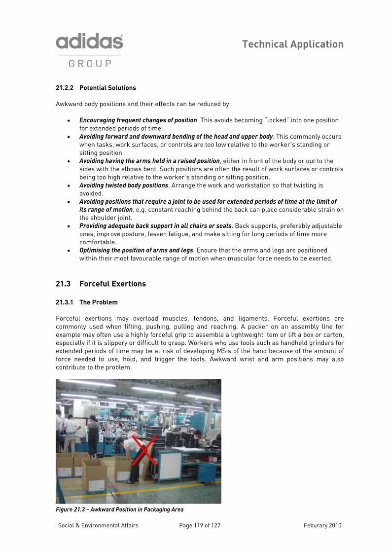
Technical Application
21.2.2 Potential Solutions
Awkward body positions and their effects can be reduced by:
• Encouraging frequent changes of position. This avoids becoming “locked” into one position for extended periods of time.
• Avoiding forward and downward bending of the head and upper body. This commonly occurs when tasks, work surfaces, or controls are too low relative to the worker’s standing or sitting position.
• Avoiding having the arms held in a raised position, either in front of the body or out to the sides with the elbows bent. Such positions are often the result of work surfaces or controls being too high relative to the worker’s standing or sitting position.
• Avoiding twisted body positions. Arrange the work and workstation so that twisting is avoided.
• Avoiding positions that require a joint to be used for extended periods of time at the limit of
its range of motion, e.g. constant reaching behind the back can place considerable strain on the shoulder joint.
• Providing adequate back support in all chairs or seats. Back supports, preferably adjustable ones, improve posture, lessen fatigue, and make sitting for long periods of time more comfortable.
• Optimising the position of arms and legs. Ensure that the arms and legs are positioned cular force needs to be exerted.
tendons, and ligaments. Forceful exertions are ommonly used when lifting, pushing, pulling and reaching. A packer on an assembly line for xample may often use a highly forceful grip to assemble a lightweight item or lift a box or carton,
a rasp. Workers who use tools such as handheld grinders for xtended periods of time may be at risk of developing MSIs of the hand because of the amount of
n r the tools. Awkward wrist and arm also o
within their most favourable range of motion when mus 21.3 Forceful Exertions
21.3.1 The Problem
Forceful exertions may overload muscles,ceespeci lly if it is slippery or difficult to geforce eeded to use, hold, and trigge
ntribute to the problem. positions may
c
Figure 21.3 – Awkward Position in Packaging Area
Social & Environmental Affairs Page 119 of 127 Feburary 2010
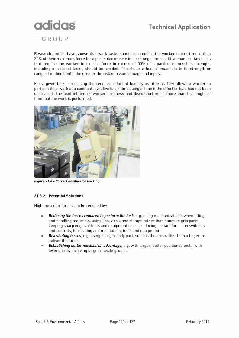
Technical Application
Research studies have shown that work tasks should not require the worker to exert more than 30% of their maximum force for a particular muscle in a prolonged or repetitive manner. Any tasks
require the worker to exert a force in excess of 50% of a particular muscle’s strength, cluding occasional tasks, should be avoided. The closer a loaded muscle is to its strength or
ange of motion limits, the greater the risk of tissue damage and injury.
or a given task, decreasing the required effort of load by as little as 10% allows a worker to
ss and discomfort much more than the length of me that the work is pe
Figure 21
ng jigs, vices, and clamps rather than hands to grip parts,
ps.
thatinr Fperform their work at a constant level five to six times longer than if the effort or load had not been decreased. The load influences worker tiredneti rformed.
.4 – Correct Position for Packing
21.3.2 Potential Solutions
High muscular forces can be reduced by:
• Reducing the forces required to perform the task, e.g. using mechanical aids when lifting and handling materials, usikeeping sharp edges of tools and equipment sharp, reducing contact forces on switches and controls, lubricating and maintaining tools and equipment.
• Distributing forces, e.g. using a larger body part, such as the arm rather than a finger, to deliver the force.
• Establishing better mechanical advantage, e.g. with larger, better positioned tools, with levers, or by involving larger muscle grou
Social & Environmental Affairs Page 120 of 127 Feburary 2010
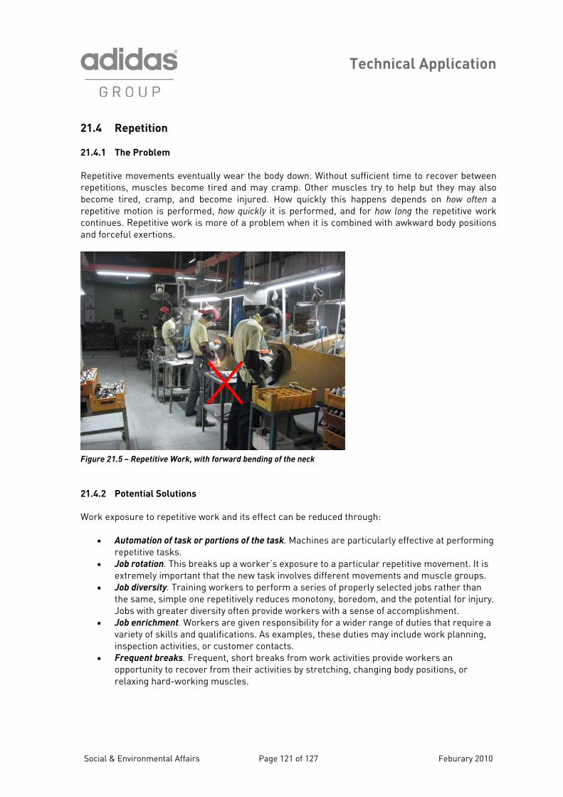
Technical Application
21.4 Repetition
1.4.1 The Problem
Repetitive movements eventually wear the body down. Without sufficient time to recover between repetitions, muscles become tired and may cramp. Other muscles try to help but they may also become tired, cramp, and become injured. How quickly this happens depends on how often a repetitive motion is performed, how quickly it is performed, and for how long the repetitive work continues. Repetitive work is more of a problem when it is combined with awkward body positions and forceful exertions.
2
Figure 21.5 – Repetitive Work, with forward bending of the neck
21.4.2 Potential Solutions
Work exposure to repetitive work and its effect can be reduced through:
• Automation of task or portions of the task. Machines are particularly effective at performing repetitive tasks.
• Job rotation. This breaks up a worker’s exposure to a particular repetitive movement. It is extremely impo w task involves different movements and muscle groups.
• Job diversity. Training o perform a series of properly selected jobs rather than the same, simple on ly reduces monotony, boredom, and the potential for injury. Jobs with greater dive n provide workers with a sense of accomplishment.
• Job enrichment. Workers are given responsibility for a wider range of duties that require a variety of skills and qualifications. As examples, these duties may include work planning, inspection activities, or customer contacts.
• Frequent breaks. Frequent, short breaks from work activities provide workers an opportunity to recover from their activities by stretching, changing body positions, or relaxing hard-working muscles.
rtant that the ne workers t
e repetitiversity ofte
Social & Environmental Affairs Page 121 of 127 Feburary 2010
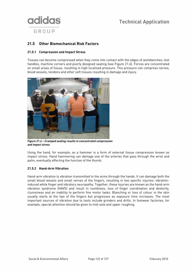
Technical Application
21.5 Other Biomechanical Risk Factors
Compression and Impact Stre
Tissues can becom l handles, machine c ntrated o ll areas of t , blood vessels, tend
21.5.1 ss
e compressed when they come into contact with the edges of workbenches, tooorners and poorly designed seating (see Figure 21.6). Forces are conce
issue, resulting in high localised pressure. This pressure can compress nervesons and other soft tissues resulting in damage and injury.
n sma
d seating results in concentrated compression F .6 – Crampe
and impact stress
Using the hand, fo as impact stress. Han d palm, eventually af 21.5.2 Hand-Arm
Hand-arm vibration nds. It can damage both the s el sulting in two specific injuries: vibration-induc d white finger and vi hese injuries are known as the hand-arm vibration syndrome , loss of finger coordination and dexterity, clumsiness and an r in the skin u at timportant sources s. In footwear factories, for e le, special at -sole and upper roughing.
igure 21
r example, as a hammer is a form of external tissue compression known d hammering can damage one of the arteries that pass through the wrist anfecting the function of the thumb.
Vibration
is vibration transmitted to the arms through the hamall blood vess s and small nerves of the fingers, re
bratory neuropathy. Together, te (HAVS) and result in numbness inability to perform fine motor tasks. Blanching or loss of colouhe tips of the fingers but progresses as exposure time increases. The most of vibration due to tools include grinders and drill
sually starts
xamp tention should be given to mid
Social & Environmental Affairs Page 122 of 127 Feburary 2010
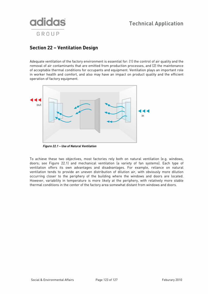
Technical Application
Section 22 – Ventilation De A ventilatio he removal of air cont ance of acceptable therm ion plays an important role in worker health a t operation of factory
sign
dequate n of the factory environment is essential for: (1) the control of air quality and taminants that are emitted from production processes, and (2) the maintenal conditions for occupants and equipment. Ventilat
nd comfort, and also may have an impact on product quality and the efficien equipment.
– Use of Natural Ventilation Figure 22.1
T these t doors; see Figure (a variety of fan systems). Each type of ventilation offers its v tion tends t ion occurring closer t e building where the windows and doors are located. H r, variabilit the periphery, with relatively more stable t al conditions area somewhat distant from windows and doors.
o achieve wo objectives, most factories rely both on natural ventilation (e.g. windows, 22.1) and mechanical ventilation
own advantages and disadvantages. For example, reliance on natural o provide an uneven distribution of dilution air, with obviously more diluto the periphery of th
entila
oweve y in temperature is more likely atherm in the center of the factory
Social & Environmental Affairs Page 123 of 127 Feburary 2010
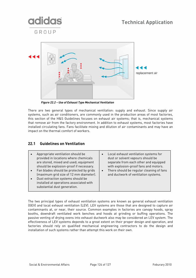
Technical Application
Social & Environmental Affairs Page 124 of 127 Feburary 2010
Figure 22.2 – Use of Exhaust Type Mechanical Ventilation
There are two general types of mechanical ventilation: supply and exhaust. Since supply air systems, such as air conditioners, are commonly used in the production areas of most factories, this section of the H&S Guidelines focuses on exhaust air systems; that is, mechanical systems that remove air from the factory environment. In addition to exhaust systems, most factories have installed circulating fans. Fans facilitate mixing and dilution of air contaminants and may have an impact on the thermal comfort of workers. 22.1 Guidelines on Ventilation The two principal types of exhaust ventilation systems are known as general exhaust ventilation (GEV) and local exhaust ventilation (LEV). LEV systems are those that are designed to capture air contaminants at, or near, their source. Common examples in factories are canopy hoods, spray booths, downdraft ventilated work benches and hoods at grinding or buffing operations. The passive venting of drying ovens into exhaust ductwork also may be considered an LEV system. The effectiveness of LEV systems depends to a great extent on their proper design and operation, and factories should rely on qualified mechanical engineering contractors to do the design and installation of such systems rather than attempt this work on their own.
• Appropriate ventilation should be provided in locations where chemicals are stored, mixed and used; equipment should be explosion-proof if necessary.
• Fan blades should be protected by grids (maximum grid size of 12 mm diameter).
• Dust extraction systems should be installed at operations associated with substantial dust generation.
• Local exhaust ventilation systems for dust or solvent vapours should be separate from each other and equipped with explosion-proof fans and motors.
• There should be regular cleaning of fans and ductwork of ventilation systems.
Technical Application
Social & Environmental Affairs Page 125 of 127 Feburary 2010
Even with proper design and operation of LEV systems, there are at least three other factors that may impact the effectiveness of these systems:
1. Proper maintenance procedures should be established and should include regular inspection, cleaning and repair, if warranted. This should encompass the entire LEV system, from the collecting hood, through the ductwork, to the fan and motor, and the discharge outlet. Lack of proper maintenance can reduce the effectiveness of LEV systems, particularly those involved in dust collection where the captured dust may settle in the ductwork.
2. Conflicting airflow patterns caused by other types of ventilation may reduce the effectiveness of LEV systems. The primary example of this situation is the strong airflow past canopy hoods that is often created by circulating fans in the aisles of production areas. While the air currents from the circulating fans may provide thermal comfort to the workers, they also reduce the effectiveness of the canopy hoods in capturing solvent vapours from the work operations.
3. Lack of instruction of the workers who work at LEV systems may also reduce their effectiveness. Workers should know how these systems should work in capturing air contaminants, so that they are more likely to employ work practices that are consistent with the protection of their health. For example, workers should know to apply chemicals under, and not outside, the edge of a canopy hood.
A variety of GEV systems may be present in factories. Examples include window exhaust fans, ceiling exhaust fans, and ducted systems with vents that pull air from the general factory environment. These systems also discharge air contaminants outside the factory, but they rely more on dilution, rather than efficient capture, to achieve acceptable air quality. Because of this, GEV systems must remove larger quantities of air than LEV systems in order to keep worker exposure below acceptable limits. With both LEV and GEV systems, care must be taken to prevent the re-entry of the air contaminants being handled by the systems. For LEV systems, the discharge point for the air should be at a substantial distance from open windows or doors. Generally, a roof location for these stacks is preferable. GEV systems should not be located near similar mechanical systems in windows or at the ceiling that supply air to the factory interior.
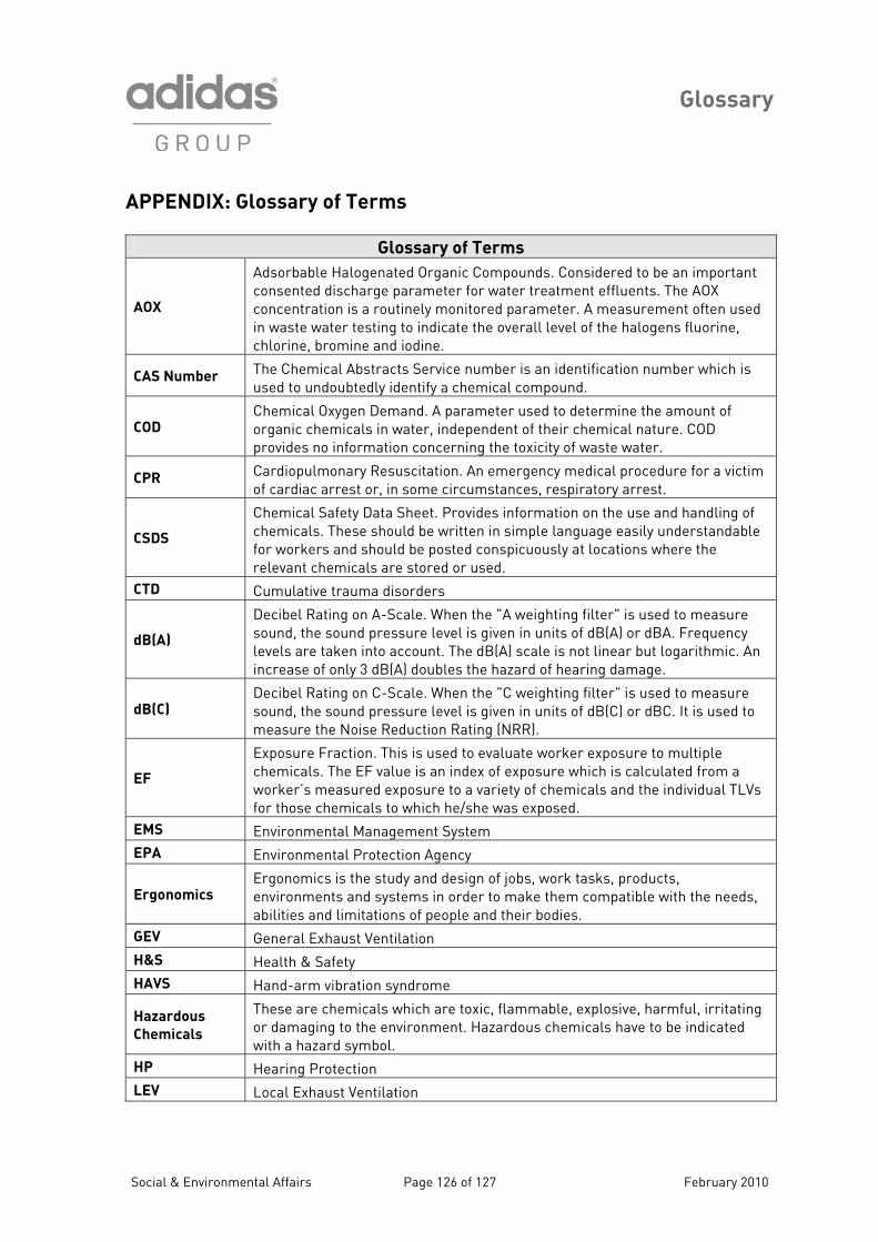
Glossary
Social & Environmental Affairs Page 126 of 127 February 2010
APPENDIX: Glossary of Terms
Glossary of Terms
AOX
Adsorbable Halogenated Organic Compounds. Considered to be an important consented discharge parameter for water treatment effluents. The AOX concentration is a routinely monitored parameter. A measurement often used in waste water testing to indicate the overall level of the halogens fluorine, chlorine, bromine and iodine.
CAS Number The Chemical Abstracts Service number is an identification number which is used to undoubtedly identify a chemical compound.
COD Chemical Oxygen Demand. A parameter used to determine the amount of organic chemicals in water, independent of their chemical nature. COD provides no information concerning the toxicity of waste water.
CPR Cardiopulmonary Resuscitation. An emergency medical procedure for a victim of cardiac arrest or, in some circumstances, respiratory arrest.
CSDS
Chemical Safety Data Sheet. Provides information on the use and handling of chemicals. These should be written in simple language easily understandable for workers and should be posted conspicuously at locations where the relevant chemicals are stored or used.
CTD Cumulative trauma disorders
dB(A)
Decibel Rating on A-Scale. When the "A weighting filter" is used to measure sound, the sound pressure level is given in units of dB(A) or dBA. Frequency levels are taken into account. The dB(A) scale is not linear but logarithmic. An increase of only 3 dB(A) doubles the hazard of hearing damage.
dB(C) Decibel Rating on C-Scale. When the "C weighting filter" is used to measure sound, the sound pressure level is given in units of dB(C) or dBC. It is used to measure the Noise Reduction Rating (NRR).
EF
Exposure Fraction. This is used to evaluate worker exposure to multiple chemicals. The EF value is an index of exposure which is calculated from a worker’s measured exposure to a variety of chemicals and the individual TLVs for those chemicals to which he/she was exposed.
EMS Environmental Management System EPA Environmental Protection Agency
Ergonomics Ergonomics is the study and design of jobs, work tasks, products, environments and systems in order to make them compatible with the needs, abilities and limitations of people and their bodies.
GEV General Exhaust Ventilation H&S Health & Safety HAVS Hand-arm vibration syndrome
Hazardous
Chemicals
These are chemicals which are toxic, flammable, explosive, harmful, irritating or damaging to the environment. Hazardous chemicals have to be indicated with a hazard symbol.
HP Hearing Protection LEV Local Exhaust Ventilation
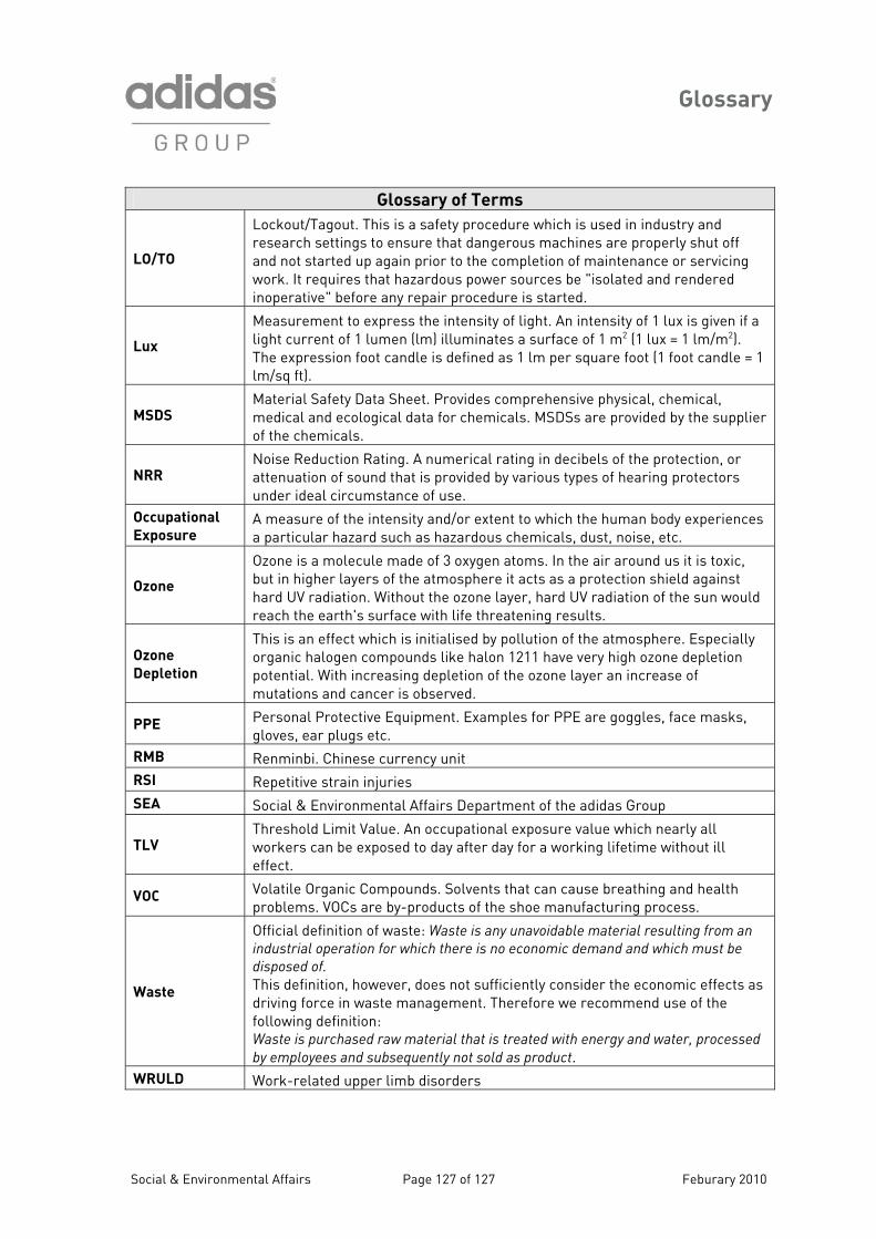
Glossary
Social & Environmental Affairs Page 127 of 127 Feburary 2010
Glossary of Terms
LO/TO
Lockout/Tagout. This is a safety procedure which is used in industry and research settings to ensure that dangerous machines are properly shut off and not started up again prior to the completion of maintenance or servicing work. It requires that hazardous power sources be "isolated and rendered inoperative" before any repair procedure is started.
Lux
Measurement to express the intensity of light. An intensity of 1 lux is given if a light current of 1 lumen (lm) illuminates a surface of 1 mP
2P (1 lux = 1 lm/mP
2P).
The expression foot candle is defined as 1 lm per square foot (1 foot candle = 1 lm/sq ft).
MSDS Material Safety Data Sheet. Provides comprehensive physical, chemical, medical and ecological data for chemicals. MSDSs are provided by the supplier of the chemicals.
NRR Noise Reduction Rating. A numerical rating in decibels of the protection, or attenuation of sound that is provided by various types of hearing protectors under ideal circumstance of use.
Occupational
Exposure A measure of the intensity and/or extent to which the human body experiences a particular hazard such as hazardous chemicals, dust, noise, etc.
Ozone
Ozone is a molecule made of 3 oxygen atoms. In the air around us it is toxic, but in higher layers of the atmosphere it acts as a protection shield against hard UV radiation. Without the ozone layer, hard UV radiation of the sun would reach the earth's surface with life threatening results.
Ozone
Depletion
This is an effect which is initialised by pollution of the atmosphere. Especially organic halogen compounds like halon 1211 have very high ozone depletion potential. With increasing depletion of the ozone layer an increase of mutations and cancer is observed.
PPE Personal Protective Equipment. Examples for PPE are goggles, face masks, gloves, ear plugs etc.
RMB Renminbi. Chinese currency unit RSI Repetitive strain injuries SEA Social & Environmental Affairs Department of the adidas Group
TLV Threshold Limit Value. An occupational exposure value which nearly all workers can be exposed to day after day for a working lifetime without ill effect.
VOC Volatile Organic Compounds. Solvents that can cause breathing and health problems. VOCs are by-products of the shoe manufacturing process.
Waste
Official definition of waste: Waste is any unavoidable material resulting from an
industrial operation for which there is no economic demand and which must be
disposed of. This definition, however, does not sufficiently consider the economic effects as driving force in waste management. Therefore we recommend use of the following definition: Waste is purchased raw material that is treated with energy and water, processed
by employees and subsequently not sold as product. WRULD Work-related upper limb disorders