heat exchanger block replacement instructions · adapter flue pipe 80mm plastic 560-907-771 1 flue...
TRANSCRIPT

Series 1-4 Gas-fired
water boiler
Part number 550-100-055/0618
Ultra-80 S1-4 Heat Exchanger Block Replacement Kit, Part No. 383-500-773Ultra-105 S1-4 Heat Exchanger Block Replacement Kit, Part No. 383-500-774Ultra-155 S1-4 Heat Exchanger Block Replacement Kit, Part No. 383-500-775Ultra-230 S1-4 Heat Exchanger Block Replacement Kit, Part No. 383-500-776Ultra-299/310/399 S1-4 Heat Exchanger Block Replacement Kit, Part No. 383-500-777
Heat Exchanger Block Replacement Instructions
Verify kit contents before proceeding with installation:
Tools/materials required
• Ultra Boiler Manual • Phillips and flat blade screwdrivers• 5/16” Nut driver• 7mm wrench or socket• 10mm wrench or socket• Pipe wrench or channel lock pliers
• T25 TORX wrench• 5/32 long-handled Allen wrench• Sawzall• PVC cement and cleaner• Silicone grease
STOP! Read before proceeding
Hazard definitionsThe following defined terms are used throughout this manual to bring attention to the presence of hazards of various risk levels or to important information concerning the life of the product.
Indicates presence of hazards that will cause severe personal injury, death or substantial property damage.
Indicates presence of hazards that can cause severe personal injury, death or substantial property damage.
Indicates special instructions on installation, operation or maintenance that are important but not related to personal injury or property damage.
These instructions must only be used by a qualified installer/service technician. Read all Instructions completely before beginning the installation. Failure to follow all instructions can cause severe personal injury, death or substantial property damage.
Improper installation, adjustment, alteration, service or maintenance can cause property damage, personal injury (exposure to hazardous materials) or loss of life. Refer to the user’s information manual provided with this boiler or available on-line at Weil-McLain.com. Installation and service must be performed by a qualified installer, service agency or the gas supplier (who must read and follow the supplied instructions before installing, servicing, or removing this boiler. This boiler contains ceramic fiber and fiberglass materials that have been identified as carcinogenic, or possibly carcinogenic, to humans).
You must refer to the Ultra Boiler Manual to follow these instructions. DO NOT proceed with the replacement procedure without having an Ultra Boiler Manual. Failure to comply can result in severe personal injury, death or substantial property damage.

Part number 550-100-055/06182
gas-fired water boilers — Heat Exchanger Block Replacement Instructions
Heat Exchanger Block Replacement Ultra 80, 105 and 155 Kits: Verify kit contents before proceeding with installation:
P/N 383-500-773 Heat Exchanger Block Kit Ultra 80 Contents:
Description Part No. QtySection Cast Aluminum Heat-Exchanger Coat 80 319-000-020 1
Bracket Flue Pipe 70mm 460-005-796 1
Adapter Air Inlet With Drain 70mm Plastic 560-907-704 1
Adapter Flue Pipe 80mm Plastic 560-907-771 1
Flue Pipe 70mm Plastic 560-907-775 1
Extension Condensate Tube w/1.46 Stub 561-200-000 1
Asy-Nut Washer Hex M6 Ø18mm OD S Zp 561-928-449 10
Clamp Pipe-Flue 70mm Ultra 562-500-001 1
Gasket Ring 70 MM - Remeha 56416 590-318-007 1
Insulation Gskt Combustion-Chamber Plt.-Cover 591-200-000 1
Instructions Block Replacement Ultra S1-4 550-100-055 1
Asy Bag T-Sensor & Adapter Hdwr UR 80/105 540-131-105 1
Contents of bag assembly:
Temperature-Sensor Flue 510-312-217 1
Igniter Electrode Double Plate 511-330-250 1
Gasket Igniter Electrode Ultra 511-330-253 1
Temperature Sensor Flue NTC 511-724-292 1
Temperature-Sensor NTC Duplex12K3 M6x1 511-724-302 2
Screw Washer Head Slotted 10-32 x 1-1/4 562-137-316 5
Screw Socket Head Cap M4x8 SS 562-100-003 2
Gasket Venturi 51 ID x 70 OD x 90 Long 590-317-310 1
Harness-Wiring for Ultra Heat-Exchanger 591-391-764 2
P/N 383-500-775 Heat Exchanger Block Kit Ultra 155 Contents:
Description Part No. QtySection Cast Aluminum Heat-Exchanger Coat 155 319-000-022 1
Bracket Flue Pipe 80mm 460-005-797 1
Adapter Air Inlet with Drain 80mm Plastic 560-907-707 1
Adapter Flue Pipe 80mm Plastic 560-907-771 1
Flue Pipe with Drain 80mm Plastic 560-907-772 1
Asy-Nut Washer Hex M6 Ø18mm OD S Zp 561-928-449 11
Clamp Pipe-Flue 80mm Ultra 562-500-002 1
Instructions Block Replacement Ultra S1-4 550-100-055 1
Asy Bag T-Sensor & Adapter Hdwr UR 155/399 540-131-106 1
Contents of bag assembly:
Temperature-Sensor Flue 510-312-217 1
Igniter Electrode Double Plate 511-330-250 1
Gasket Igniter Electrode Ultra 511-330-253 1
Temperature Sensor Flue NTC 511-724-292 1
Temperature-Sensor NTC Duplex12K3 M6x1 511-724-302 2
Screw Washer Head Slotted 10-32 x 1-1/4 562-137-316 5
Screw Socket Head Cap M4x8 SS 562-100-003 2
Plate Locking - Remeha 57351 562-248-708 3
Screw Machine Hex Head M4-.7x10 SS 562-650-121 3
Harness-Wiring for Ultra Heat-Exchanger 591-391-764 2
Asy Box Insl Plate-Cover & Gasket UR 155-399 540-131-107 1
Contents of box assembly:
Gasket Chamber Cover Plate Remeha 54752 590-318-005 1
Insulation Plate-Cover/Burner 418.5x180x4mm 590-318-032 1
P/N 383-500-774 Heat Eachanger Block Kit Ultra 105 Contents:
Description Part No. QtySection Cast Aluminum Heat-Exchanger Coat 105 319-000-021 1
Bracket Flue Pipe 70mm 460-005-796 1
Adapter Air Inlet With Drain 70mm Plastic 560-907-704 1
Adapter Flue Pipe 80mm Plastic 560-907-771 1
Flue Pipe 70mm Plastic 560-907-775 1
Asy-Nut Washer Hex M6 Ø18mm OD S Zp 561-928-449 10
Clamp Pipe-Flue 70mm Ultra 562-500-001 1
Gasket Ring 70 MM - Remeha 56416 590-318-007 1
Insulation Gskt Combustion-Chamber Plt.-Cover 591-200-000 1
Instructions Block Replacement Ultra S1-4 550-100-055 1
Asy Bag T-Sensor & Adapter Hdwr UR 80/105 540-131-105 1
Contents of bag assembly:
Temperature-Sensor Flue 510-312-217 1
Igniter Electrode Double Plate 511-330-250 1
Gasket Igniter Electrode Ultra 511-330-253 1
Temperature Sensor Flue NTC 511-724-292 1
Temperature-Sensor NTC Duplex12K3 M6x1 511-724-302 2
Screw Washer Head Slotted 10-32 x 1-1/4 562-137-316 5
Screw Socket Head Cap M4x8 SS 562-100-003 2
Gasket Venturi 51 ID x 70 OD x 90 Long 590-317-310 1
Harness-Wiring for Ultra Heat-Exchanger 591-391-764 2

Part number 550-100-055/0618 3
gas-fired water boilers — Heat Exchanger Block Replacement Instructions
P/N 383-500-776 Block Kit Ultra 230 Contents:
Description Part No. Qty
Section Cast Aluminum Heat-Exchanger Coat 230 319-000-023 1
Bracket Flue Pipe 100mm 460-005-798 1
Adapter Air Inlet 100mm Plastic 560-907-710 1
Adapter Flue Pipe 100mm Plastic 560-907-773 1
Flue Pipe with Drain 100mm Plastic 560-907-774 1
Asy-Nut Washer Hex M6 Ø18mm OD S Zp 561-928-449 13
Clamp Pipe-Flue 100mm Ultra 562-500-003 1
Instructions Block Replacement Ultra S1-4 550-100-055 1
Asy Bag T-Sensor & Adapter Hdwr UR 155/399 540-131-106 1
Contents of bag assembly:
Temperature-Sensor Flue 510-312-217 1
Igniter Electrode Double Plate 511-330-250 1
Temperature Sensor Flue NTC 511-724-292 1
Gasket Igniter Electrode Ultra 511-330-253 1
Temperature-Sensor NTC Duplex12K3 M6x1 511-724-302 2
Screw Washer Head Slotted 10-32 x 1-1/4 562-137-316 5
Screw Socket Head Cap M4x8 SS 562-100-003 2
Plate Locking - Remeha 57351 562-248-708 3
Screw Machine Hex Head M4-.7x10 SS 562-650-121 3
Harness-Wiring for Ultra Heat-Exchanger 591-391-764 2
Asy Box Insl Plate-Cover & Gasket UR 155-399 540-131-107 1
Contents of box assembly:
Gasket Chamber Cover Plate Remeha 54752 590-318-005 1
Insulation Plate-Cover/Burner 418.5x180x4mm 590-318-032 1
P/N 383-500-777 Block Kit Ultra 299/310/399 Contents:
Description Part No. Qty
Section Cast Al. Heat-Exch. Coat 299/310/399 319-000-024 1
Bracket Flue Pipe 100mm 460-005-798 1
Adapter Air Inlet 100mm Plastic 560-907-710 1
Adapter Flue Pipe 100mm Plastic 560-907-773 1
Flue Pipe with Drain 100mm Plastic 560-907-774 1
Asy-Nut Washer Hex M6 Ø18mm OD S Zp 561-928-449 13
Washer 1.26 ID x 1.74 OD x .06 Garlock 562-248-755 2
Clamp Pipe-Flue 100mm Ultra 562-500-003 1
Instructions Block Replacement Ultra S1-4 550-100-055 1
Asy Bag T-Sensor & Adapter Hdwr UR 155/399 540-131-106 1
Contents of bag assembly:
Temperature-Sensor Flue 510-312-217 1
Igniter Electrode Double Plate 511-330-250 1
Temperature Sensor Flue NTC 511-724-292 1
Gasket Igniter Electrode Ultra 511-330-253 1
Temperature-Sensor NTC Duplex12K3 M6x1 511-724-302 2
Screw Washer Head Slotted 10-32 x 1-1/4 562-137-316 5
Screw Socket Head Cap M4x8 SS 562-100-003 2
Plate Locking - Remeha 57351 562-248-708 3
Screw Machine Hex Head M4-.7x10 SS 562-650-121 3
Harness-Wiring for Ultra Heat-Exchanger 591-391-764 2
Asy Box Insl Plate-Cover & Gasket UR 155-399 540-131-107 1
Contents of box assembly:
Gasket Chamber Cover Plate Remeha 54752 590-318-005 1
Insulation Plate-Cover/Burner 418.5x180x4mm 590-318-032 1
Block Replacement Ultra 230, 299, 310 and 399 Kits: Verify kit contents before proceeding with installation:

Ultra jacket and front top cover removal
Part number 550-100-055/06184
gas-fired water boilers — Heat Exchanger Block Replacement Instructions
The boiler contains ceramic fiber materials. Use care when handling these materials per Ultra Boiler Manual. Failure to comply could result in severe personal injury.
ELECTRICAL SHOCK HAZARD — For your safety, turn off electrical power supply at service entrance panel before making any electrical connections to avoid possible elec-tric shock hazard. Failure to do so can cause severe personal injury or death.
Refer to the Ultra Boiler Manual for compo-nent locations and illustrations.
You must refer to the Ultra Boiler Manual to follow these instructions. DO NOT proceed with the replacement procedure without having an Ultra Boiler Manual. Failure to comply can result in severe personal injury, death or substantial property damage.
STOP! Read before proceeding
Shut off power to the boiler and close main gas valve. Close all isolation valves. Failure to do so can result in severe personal injury, death or substantial property damage.
Wait for the heat exchanger to cool down before proceeding. Failure to do so can result in severe personal injury.
Reinstall boiler front door after start-up or servicing. The boiler front door must be securely fastened to the boiler to prevent boiler from drawing air from inside the boiler room. This is particularly important if the boiler is located in the same room as other appliances.
Inspect boiler jacket door gaskets. Gaskets must be in good condition, with no tears or gaps. Replace if necessary.
Failure to keep the door securely sealed and fastened could result in severe personal injury or death.
Removing and reinstalling components can change boiler behavior. After any maintenance procedure, you must prove the boiler is oper-ating correctly. To do so, follow the complete procedure for boiler and system start-up as instructed in the Boiler Manual. Failure to comply could result in severe personal injury, death or substantial property damage.
Turn off gas before replacing air inlet adapter. If boiler is hot from operation, allow time to cool before proceeding. Failure to do so can cause severe personal injury, death, or sub-stantial property damage.
Ultra boilers should not be installed into a common vent with any other appliance. This will cause flue gas spillage or appliance mal-function, resulting in possible severe personal injury, death, or substantial property damage.
Replacement instructions:1. Verify with packing list that you have the correct kit
contents. 2. Turn off and disconnect power from the boiler.3. Remove the boiler front jacket panel by loosening the (2)
screws at the bottom of the front panel with a flat blade screwdriver. Once screws are loose, lift front jacket panel
and pull forward to remove from boiler, see Figure 1.4. Remove four (4) screws from the top black front plastic
panel using a Phillips head screwdriver.
Figure 1 Front door removal

Part number 550-100-055/0618 5
gas-fired water boilers — Heat Exchanger Block Replacement Instructions
5. Remove the (4) Phillips head screws from the top rear plastic panel.
6. Remove and discard flue sensor and grommet from stainless vent pipe inside boiler, see Figure 3.
Figure 2 Front top removal
Label wires before removing Label all wires prior to disconnection when ser-
vicing controls. Wiring errors can cause improper and dangerous operation.
7. Loosen the PVC band clamp at the vent and intake adapters using a 5/16” nut driver.
8. If possible remove the PVC vent and intake pipes from the adapter. If not enough free movement of the vent and intake
Figure 3 Flue sensor removal
pipes, cut either or both the PVC intake and vent pipes above the top of the vent and intake adapters for adequate clearance.
Figure 4 Flue pipe cut off for removal
PVC air pipe must be supported. Failure to do so could result in damage to the air pipe system.
9. Remove the (5) screws with a 5/16” nut driver from the intake and the vent adapter by moving the top plastic cover to gain access to the screws, see Figure 5.
10. Remove and discard the intake adapter by breaking it loose from the top panel gasket. Remove and discard the vent adapter by pulling straight up on the vent adapter while rocking it side to side to remove the adapter from the flue outlet of the heat exchanger.
Figure 5 Flue clamp loosened for flue pipe removal

Ultra-80 - 105 Heat Exchanger Block Replacement
Part number 550-100-055/06186
gas-fired water boilers — Heat Exchanger Block Replacement Instructions
11. Cover the heat exchanger flue outlet with a rag or tape to prevent plastic particles from entering.
12. Raise the front of the top rear plastic panel as much as possible and support it securely so as to cut a portion of the inside piece away as shown in the Figure 6, (required for Ultra 299/310/399 only). This will allow proper fit of the top rear panel with the new Poly Pro intake and vent adapters.
13. With a sawzall or other appropriate cutting device, cut approximately 1” up and across from side to side as shown in the photo. Vacuum and/or clean all plastic cutting residue from boiler top panel, top of heat exchanger and from inside boiler jacket.
Figure 6 Plastic flange removal for new vent adapters
14. Remove support holding top rear plastic panel and let panel rest on top boiler panel.
Refer to the Ultra Boiler Manual for compo-nent locations and illustrations
Weil-McLain changed the Ultra heat exchanger sensors in June 2014. Ultra Series 1 & 2 boilers utilized a supply and return temperature sensor that has an M4 thread with two stake on terminals. Series 3 Ultra boilers utilize a supply and return temperature sensor that has an M4 thread with a 4 pin molex connector. After June 2014, Weil-McLain began using a supply and return sensor with an M6 thread with a 4 pin molex connector.
All replacement heat exchangers come with the supply and return sensor with the M6 thread. To connect the sensors to the Ultra Series 3 wiring, simply plug in the supply and return, 4 pin molex connector to the new sensors in the heat exchanger. To connect the new sensors in the replacement heat exchanger to the Ultra Series 1 & 2 sensor wiring, two (2) 4 pin molex adapters with butt connectors are included with the heat exchanger replacement kit. To connect the new 4 pin molex connectors to the Series 1 & 2 wiring, cut and strip the boiler sensor wiring close to the stake on terminals, connect and crimp the sensor wires into the butt connectors of the adapters. After crimping the butt connectors, plug in the 4 pin molex connector to the supply sensor and the return sensor.
• This heat exchanger is coated to extend the intervals between cleanings. Cleaning the heat exchanger via mechanical means (cleaning tools, blade, or brush) could shorten the life of the coating.
• Heat exchanger inspection is recommended at year-ly intervals. Only clean heat exchanger if soiling is clearly present. If cleaning is necessary flush only with water and a mild detergent. From the cover plate opening, inspect the collection area and un-derneath the vent pipe to ensure that it is free of de-bris. If cleaning is necessary flush only with water and a mild detergent.
• Cleaning the heat exchanger should not be neces-sary until 5 years after commissioning date.
NOTICE !For new Ultra Series 3 boilers manufactured after
July 2016 (tagged, and visually marked/stamped on the
right side of the block):
Limit cleaning to the use of vacuum or water-only rinsing for the first 5 years of
operation. No tool cleaning is necessary.
Ultra-80 & Ultra-105 Cover Plate Replacement
Part number 550-100-055/0618 7
gas-fired water boilers — Heat Exchanger Block Replacement Instructions
Wait for the heat exchanger to cool down before proceeding. Failure to do so can result in severe personal injury.
1. Close external isolation valves on boiler water supply and return.
2. Drain water from boiler using boiler drain valve.3. Close manual gas valve to shut off gas supply.4. Disconnect gas valve electrical plug and water temperature
sensors. Disconnect two (2) electrical plugs from blower assembly.
5. Remove four (4) Phillips-head screws securing gas valve inlet adapter to gas valve. This will disconnect the gas valve from the gas line.
6. Remove the air silencer by separating it from the air adapter on the blower inlet.
7. For the older style heat exchanger cover plate, use a 5/32 A l l e n w r e n c h w i t h a 5 / 1 6 ” w r e n c h t o r e -move the two (2) 5/32” Allen head screws securing the blower and gas valve assemby to the cover plate. For the new style heat exchanger cover plate, studs are used instead of bolts and nuts. So remove the two (2) nuts with a 5/16” wrench from the studs. Then remove the blower from the cover plate.
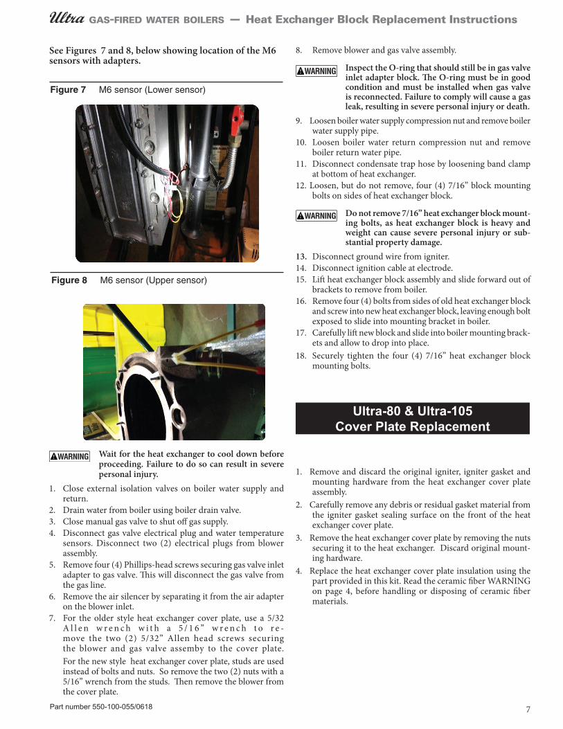
Figure 7 M6 sensor (Lower sensor)
Figure 8 M6 sensor (Upper sensor)
See Figures 7 and 8, below showing location of the M6 sensors with adapters.
8. Remove blower and gas valve assembly.
Inspect the O-ring that should still be in gas valve inlet adapter block. The O-ring must be in good condition and must be installed when gas valve is reconnected. Failure to comply will cause a gas leak, resulting in severe personal injury or death.
9. Loosen boiler water supply compression nut and remove boiler water supply pipe.
10. Loosen boiler water return compression nut and remove boiler return water pipe.
11. Disconnect condensate trap hose by loosening band clamp at bottom of heat exchanger.
12. Loosen, but do not remove, four (4) 7/16” block mounting bolts on sides of heat exchanger block.
Do not remove 7/16” heat exchanger block mount-ing bolts, as heat exchanger block is heavy and weight can cause severe personal injury or sub-stantial property damage.
13. Disconnect ground wire from igniter.14. Disconnect ignition cable at electrode.15. Lift heat exchanger block assembly and slide forward out of
brackets to remove from boiler. 16. Remove four (4) bolts from sides of old heat exchanger block
and screw into new heat exchanger block, leaving enough bolt exposed to slide into mounting bracket in boiler.
17. Carefully lift new block and slide into boiler mounting brack-ets and allow to drop into place.
18. Securely tighten the four (4) 7/16” heat exchanger block mounting bolts.
1. Remove and discard the original igniter, igniter gasket and mounting hardware from the heat exchanger cover plate assembly.
2. Carefully remove any debris or residual gasket material from the igniter gasket sealing surface on the front of the heat exchanger cover plate.
3. Remove the heat exchanger cover plate by removing the nuts securing it to the heat exchanger. Discard original mount-ing hardware.
4. Replace the heat exchanger cover plate insulation using the part provided in this kit. Read the ceramic fiber WARNING on page 4, before handling or disposing of ceramic fiber materials.

Part number 550-100-055/06188
gas-fired water boilers — Heat Exchanger Block Replacement Instructions
Figure 9 Nut tightening sequence — 80 & 105 Gradually tighten the nuts, repeating the sequence shown below until the torque reaches 50 inch-pounds (+/- 10 inch-pounds.
6. Install new igniter, gasket and mounting hardware provided in this kit. Secure the ground wire ring terminal with mounting screw. Reconnect ignition cable to igniter.
7. Install new cork gasket to intlet flange of the heat exchanger cover plate.
8. Reinstall blower/venturi/gas valve, ensuring the O-ring is properly seated in gas valve inlet adapter block. Secure gas valve to block with four (4) Phillips-head screws. Secure venturi to cover plate with original screws.
The O-ring must be in good condition and must be installed in the inlet adapter when gas valve is re-connected. Failure to comply will cause a gas leak, resulting in severe personal injury or death.
9. Reinstall boiler water supply pipe and tighten compression nut.
10. Reinstall boiler return water pipe and tighten compression nut.11. Install Poly Pro intake adapter by inserting into top boiler
panel intake opening. Align the screw mounting lugs and secure the intake adapter with new 5/16” screws provided in this kit. For Ultra 80 & 105 only, also align small intake drain nipple to the 4:00 position from the front of the boiler. This will allow moisture from the boiler intake to drip onto the heat exchanger and evaporate with heat Secure the in-take adapter with new 5/16” screws provided in this kit.
12. Insert the Poly Pro vent adapter into the boiler top panel opening and down into the heat exchanger vent opening. Insert Poly Pro vent down into heat exchanger flue outlet
until the vertical arrows ò ò are touching the top
of the flue outlet, see Figure 10.
Figure 10 Flue arrow alignment
13. Ensure heat exchanger blue gasket is in proper position. Use small amount of silicone grease to lubricate the bottom of the Poly Pro vent to allow easy placement into heat exchanger flue outlet.
14. Align L bracket with circular hole to the condensate drain on boiler and slide up, see Figure 11 below.
Figure 11 L bracket slid over condensate drain
5. Secure the original cover plate to the replacement heat ex-changer block mounted inside of the boiler cabinet. For Ultra-80 and Ultra-105, follow the tightening sequence shown in Figure 9 below making a minimum of two passes with a torque wrench. Final torque = 50 +/- 10 inch-pounds.

Part number 550-100-055/0618 9
gas-fired water boilers — Heat Exchanger Block Replacement Instructions
15. Place snap style clamp around Poly Pro vent pipe and around the rectangle “Offset flange” of L bracket. Be sure clamp is 1/8” above the lip of the first section of the Poly Pro vent pipe, see Figure 12 below. Secure clamp by snapping lever.
Figure 12 Offset flange of L bracket, clamp in place
16. Ensure the condensate drain plastic nipple is protruding from the bottom of the condensate drain of the boiler. Align vent adapter so flue sensor opening is toward front of boiler.
17. Install Poly Pro vent adapter and align screw lugs. Secure the intake adapter with new 5/16” screws provided in this kit, see Figure 13.
18. Reinstall new flue sensor to grommet in the vent pipe.
19. Reinstall the four (4) Phillips head screws in the top rear plastic panel.
20. Reinstall the front plastic panel with the four (4) Phillips head screws removed earlier.
21. Reconnect the vent and intake PVC into the new Poly Pro adapters ensuring the adapter gaskets are properly in place. If the PVC vent and/or intake had to be cut, install a repair coupling to connect the two pieces of vent/intake. Utilize proper PVC gluing technique.
22. Clean out any PVC shavings from the area.
23. Inspect the venting system for any shifting or damage during the procedure. Check the termination, support, and rubber boot if using a through-the-roof installation.
24. Open the external isolation valves on boiler water supply and return.
25. Fill boiler with water, purge air from boiler and check for leaks.26. Reinstall condensate trap and tighten band clamp. 27. Reinstall air silencer. 28. Reconnect the two (2) blower electrical plugs, water tempera-
ture sensors and gas valve electrical plug.29. Turn on gas supply and check for gas leaks.
Inspect the gas pipe fitting connections on the gas valve, checking the seal of the connections. Failure to comply will cause a gas leak, resulting in severe personal injury or death.
Do not check for gas leaks with an open flame — use bubble test. Failure to use bubble test or check for gas leaks can cause severe personal injury, death or substantial property damage.
30. Turn on boiler electrical supply.
Replace boiler jacket front door after servicing. The boiler front door must be securely fastened to the boiler to prevent boiler from drawing air from in-side the boiler room. This is particularly important if the boiler is located in the same room as other ap-pliances. Failure to keep the door securely fastened could result in severe personal injury or death.
31. Restore boiler to normal operation.
Perform complete start-up procedure1. Follow all instructions in the Ultra Boiler Manual to start
up, test and adjust the boiler.2. Make sure to perform the inspection mirror leak test around
all flue gas joints as instructed in the boiler Start-up section of the manual.
Removing and reinstalling components can change boiler behavior. After any maintenance procedure, you must prove the boiler is operating correctly. To do so, follow the complete procedure for boiler and system start-up as instructed in the Ultra Boiler Manual. Failure to comply could result in severe personal injury, death or substantial property damage.
Figure 13 Vent adapter screw lugs aligned

Part number 550-100-055/061810
gas-fired water boilers — Heat Exchanger Block Replacement Instructions
Ultra-155, -230, 299, 310 & 399 Heat Exchanger Block Replacement
You must refer to the Ultra Boiler Manual to follow these instructions. DO NOT proceed with the replacement procedure without having an Ultra Boiler Manual. Failure to comply can result in severe personal injury, death or substantial property damage.
The boiler contains ceramic fiber materi-als. Use care when handling these materi-als per Ultra Boiler Manual. Failure to comply could result in severe personal injury.
ELECTRICAL SHOCK HAZARD — For your safety, turn off electrical power supply at service entrance panel before making any electrical connections to avoid possible electric shock hazard. Failure to do so can cause severe personal injury or death.
Refer to the Ultra Boiler Manual for compo-nent locations and illustrations.
Weil-McLain changed the Ultra heat exchanger sen-sors in June 2014. Ultra Series 1 & 2 boilers utilized a supply and return temperature sensor that has an M4 thread with two stake on terminals. Series 3 Ultra boilers utilize a supply and return temperature sensor that has an M4 thread with a 4 pin molex con-nector. After June 2014, Weil-McLain began using a supply and return sensor with an M6 thread with a 4 pin molex connector.
All replacement heat exchangers come with the supply and return sensor with the M6 thread. To connect the sensors to the Ultra Series 3 wiring, simply plug in the supply and return, 4 pin molex connector to the new sensors in the heat exchanger. To connect the new sensors in the replacement heat exchanger to the Ultra Series 1 & 2 sensor wiring, two (2) 4 pin molex adapters with butt connectors are included with the heat exchanger replacement kit. To connect the new 4 pin molex connectors to the Series 1 & 2 wiring, cut and strip the boiler sensor wiring close to the stake on terminals, connect and crimp the sensor wires into the butt connectors of the adapters. After crimping the butt connectors, plug in the 4 pin molex connector to the supply sensor and the return sensor.
See Figures 14 below and 15 on page 11, showing location of the M6 sensors with adapters.
STOP! Read before proceeding
Shut off power to the boiler and close main gas valve. Close all isolation valves. Failure to do so can result in severe personal injury, death or substantial property damage.
Wait for the heat exchanger to cool down before proceeding. Failure to do so can result in severe personal injury.
Reinstall boiler front door after start-up or servicing. The boiler front door must be securely fastened to the boiler to prevent boiler from drawing air from inside the boiler room. This is particularly important if the boiler is located in the same room as other appliances.
Inspect boiler jacket door gaskets. Gaskets must be in good condition, with no tears or gaps. Replace if necessary.
Failure to keep the door securely sealed and fastened could result in severe personal injury or death.
Removing and reinstalling components can change boiler behavior. After any mainte-nance procedure, you must prove the boiler is operating correctly. To do so, follow the complete procedure for boiler and system start-up as instructed in the Boiler Manual. Failure to comply could result in severe per-sonal injury, death or substantial property damage.
Figure 14 M6 sensor (Lower sensor)
NOTICE !For new Ultra Series 3 boilers manufactured after
July 2016 (tagged, and visually marked/stamped on the right side of the block):
Limit cleaning to the use of vacuum or water-only rinsing for the first 5 years of operation.
No tool cleaning is necessary.

Part number 550-100-055/0618 11
gas-fired water boilers — Heat Exchanger Block Replacement Instructions
1. Remove and discard the original igniter, igniter gasket and mounting hardware from the heat exchanger cover plate assembly.
2. Carefully remove any debris or residual gasket material from the igniter gasket sealing surface on the front of the heat exchanger cover plate.
3. Remove the heat exchanger cover plate by removing the nuts securing it to the heat exchanger. Discard original mount-ing hardware.
4. Remove the three (3) M4 hex head screws (7mm box end wrench) and burner clips securing the burner to the cover plate. Discard original mounting hardware.
5. Remove burner and original cover plate insulation. Read the ceramic fiber WARNING on page 4 before handling or disposing of ceramic fiber materials.
6. Replace the heat exchanger cover plate insulation using the part provided in this kit.
7. Reinstall the burner using the hex head screws and burner clips provided in this kit per instructions in your Ultra boiler manual.
8. Secure the original cover plate to the replacement heat ex-changer mounted inside of the boiler cabinet. For Ultra-155 through Ultra-399, follow the tightening sequence shown in Figure 16 below making a minimum of two passes with a torque wrench. Final torque = 50 +/- 10 inch-pounds.
1. Close external isolation valves on boiler water supply and return. Drain water from boiler using boiler drain valve.
2. Close manual gas valve to shut off gas supply.
Wait for the heat exchanger to cool down before proceeding. Failure to do so can result in severe personal injury.
Label wires before removing Label all wires prior to disconnection when ser-
vicing controls. Wiring errors can cause improper and dangerous operation.
3. Disconnect gas valve electrical plug and water temperature sensors. Disconnect two (2) electrical plugs from blower assembly.
4. Disconnect gas line union with pipe wrench or channel lock pliers.
5. Remove air silencer by lifting plastic clamp off gas line and then gently sliding air silencer down and off valve.
6. Remove two (2) 5/32” Allen head screws securing blower assembly to heat exchanger front cover.
7. Remove blower and gas valve assembly.8. Loosen boiler water supply pipe nut and remove boiler water
supply pipe. 9. Loosen boiler water return pipe nut and remove boiler return
water pipe.10. Disconnect condensate trap hose by loosening band clamp
at bottom of heat exchanger.11. Loosen, but do not remove, four (4) 7/16” block mounting
bolts on sides of heat exchanger block.
Do not remove 7/16” heat exchanger block mount-ing bolts, as heat exchanger block is heavy and weight can cause severe personal injury or sub-stantial property damage.
12. Disconnect ground wire from igniter.13. Disconnect ignition cable at electrode. 14. Lift heat exchanger block assembly and slide forward out of
brackets to remove from boiler. 15. Remove four (4) bolts from sides of old heat exchanger block
and screw into new heat exchanger block, leaving enough bolt exposed to slide into mounting bracket in boiler.
16. Carefully lift new block and slide into boiler mounting brack-ets and allow to drop into place.
17. Securely tighten the four (4) 7/16” heat exchanger block mounting bolts.
Figure 15 M6 sensor (Upper sensor)
Ultra-155 through 399 Cover Plate Replacement
Figure 16 Nut tightening sequence — 155 to 399 — Gradually tighten the nuts, repeating the sequence shown below until the torque reaches 50 inch-pounds (+/- 10 inch-pounds).

12 Part number 550-100-055/0618
gas-fired water boilers — Heat Exchanger Block Replacement Instructions
9. Install new igniter, gasket and mounting hardware provided in this kit. Secure the ground wire ring terminal with mount-ing screw.
10. Reconnect ignition cable to igniter.11. Reinstall blower to heat exchanger cover plate with bolts and
nuts or with the two (2) nuts if studs are used in the cover plate. Insure gasket is seated properly.
12. Reconnect gas line union with pipe wrench or channel lock pliers.
Flue/Inlet Air Installation follow Steps 11-17, pages 8 & 9
13. Reinstall boiler water supply pipe and tighten pipe nut. 14. Reinstall boiler return water pipe and tighten pipe nut. 15. Install new flue sensor to grommet in the vent pipe.
16. Reinstall the four (4) Phillips head screws in the top rear plastic panel.
17. Reinstall the front plastic panel with the four (4) Phillips head screws removed earlier.
18. Reconnect the vent and intake PVC into the new Poly Pro adapters ensuring the adapter gaskets are properly in place. If the PVC vent and/or intake had to be cut, install a repair coupling to connect the two pieces of vent/intake. Utilize proper PVC gluing technique.
19. Clean out any PVC shavings from the area.
20. Inspect the venting system for any shifting or damage during the procedure. Check the termination, support, and rubber boot if using a through-the-roof installation.
21. Open the external isolation valves on boiler water supply and return.
22. Fill boiler with water, purge air from boiler, and check for leaks.
23. Reinstall condensate trap and tighten band clamp. 24. Reinstall air silencer by sliding on gas valve venturi and
securing clamp to gas line. 25. Reconnect the two (2) blower electrical plugs, water tem-
perature sensors and gas valve electrical plug. 26. Turn on gas supply and check for gas leaks.
Inspect the gas pipe fitting connections on the gas valve, checking the seal of the connections. Failure to comply will cause a gas leak, resulting in severe personal injury or death.
Do not check for gas leaks with an open flame — use bubble test. Failure to use bubble test or check for gas leaks can cause severe personal injury, death or substantial property damage.
27. Turn on boiler electrical supply.
Replace boiler jacket front door after servicing. The boiler front door must be securely fastened to the boiler to prevent boiler from drawing air from inside the boiler room. This is particularly important if the boiler is located in the same room as other appliances. Failure to keep the door securely fastened could result in severe personal injury or death.
28. Restore boiler to normal operation.
Perform complete start-up procedure1. Follow all instructions in the Ultra Boiler Manual to start
up, test and adjust the boiler.2. Make sure to perform the inspection mirror leak test around
all flue gas joints as instructed in the boiler Start-up section of the manual.
Removing and reinstalling components can change boiler behavior. After any maintenance procedure, you must prove the boiler is operating correctly. To do so, follow the complete procedure for boiler and system start-up as instructed in the Ultra Boiler Manual. Failure to comply could re-sult in severe personal injury, death or substantial property damage.