heat integration study of combined cycle gas turbine...
TRANSCRIPT
Heat Integration study of Combined Cycle Gas Turbine
(CCGT) Power Plant Integrated With Post-combustion CO2
Capture (PCC) and Compression
Xiaobo LuoMeihong Wang
Process/Energy System Engineering and CCS GroupUniversity of Hull

OUTLINE
Motivation
Model Development
Integration of CCGT, PCC and compression
Case studies
Summary

Motivation
(Source: Vostok ice core data/J.R. Petit et al.; NOAA Mauna Loa CO2 record)
anthropogenic
CO2
emission
Motivation
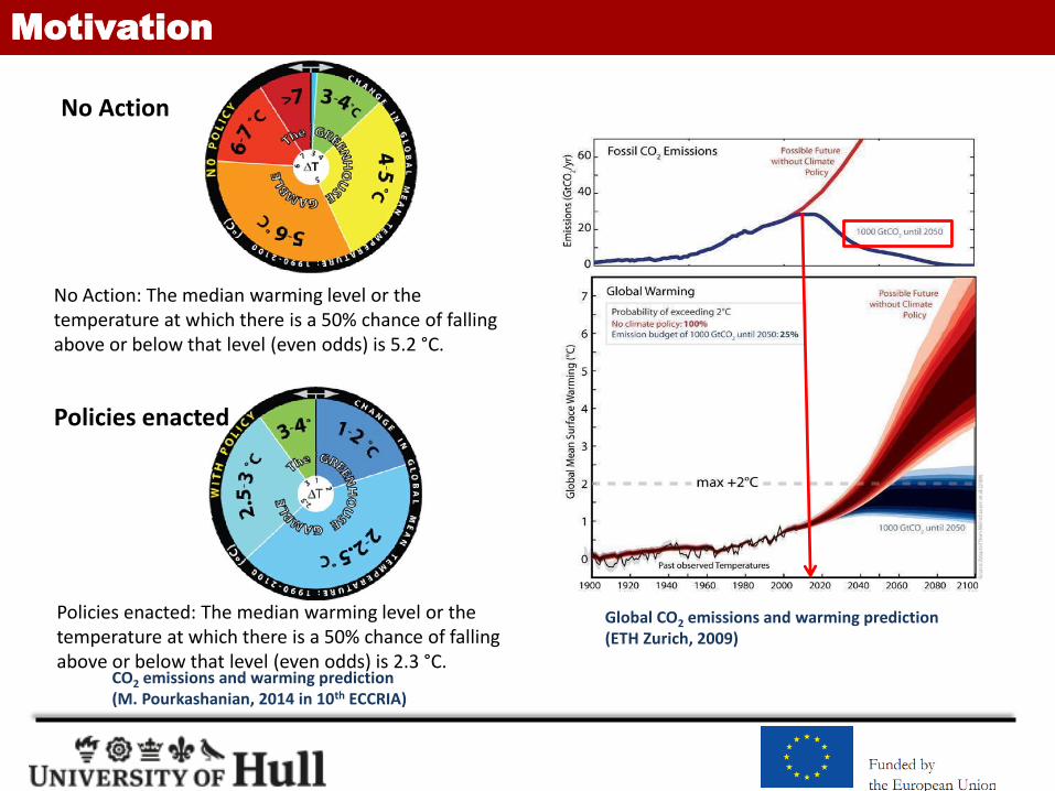
Global CO2 emissions and warming prediction (ETH Zurich, 2009)
CO2 emissions and warming prediction (M. Pourkashanian, 2014 in 10th ECCRIA)
No Action: The median warming level or the temperature at which there is a 50% chance of falling above or below that level (even odds) is 5.2 °C.
Policies enacted: The median warming level or the temperature at which there is a 50% chance of falling above or below that level (even odds) is 2.3 °C.
No Action
Policies enacted
Motivation

Motivation
BLUE map emission reduction plant (IEAGHG, 2012)
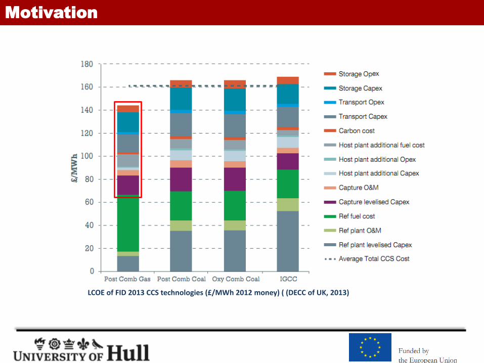
LCOE of FID 2013 CCS technologies (£/MWh 2012 money) ( (DECC of UK, 2013)
Motivation

Motivation
• model development and validation of CCGT power plant
• model development and validation of PCC and CO2 compression
• process integration between CCGT and PCC and compression
• Case studies including evaluation of heat integration options
Aim
Objectives
• The aim of this study is to evaluate integration options of CCGT power plant with PCC process and compressors via process modelling and simulation, in order to improve the thermal efficiency of the power plant and to reduce the cost of CCS deployment.
Technical readiness
Better economic improvements
Financial Support
Engineering R&D

CCGT Model Development and Validation
Combined-Cycle Gas Turbine Power Plant Schematic (Source: Calpine 2012)
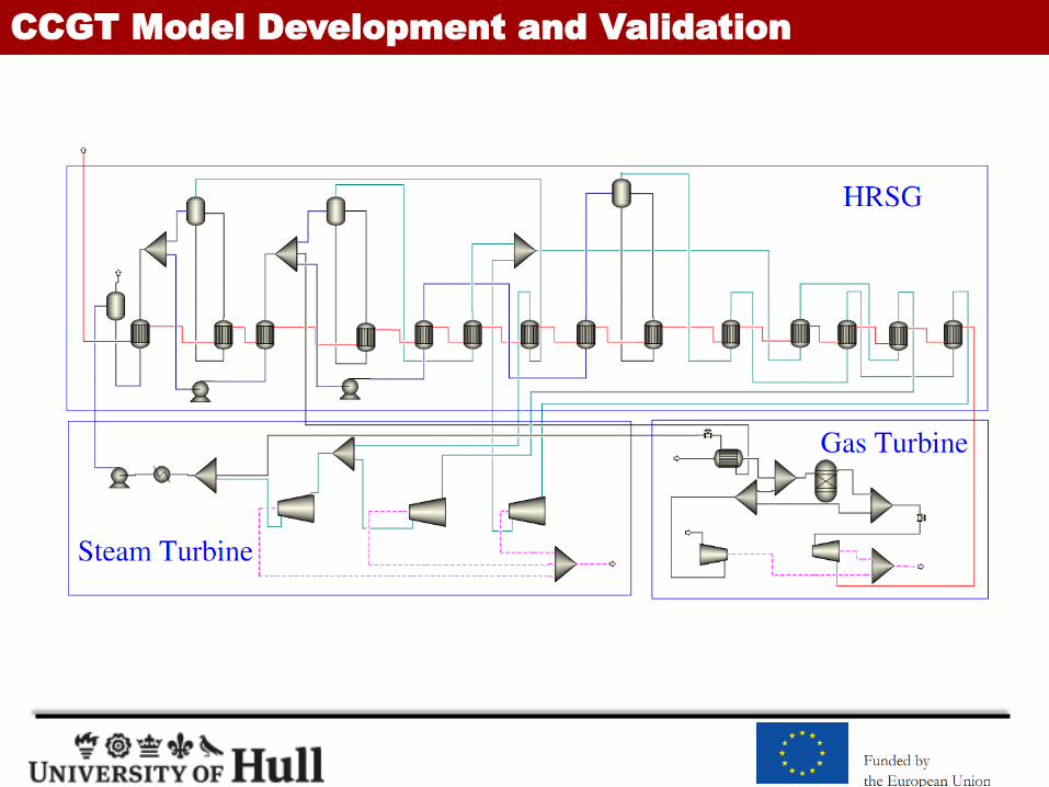
CCGT Model Development and Validation

CCGT Model Development and Validation
Net power output: 453MWe
Gas turbine model: GE 9371FB
HRGS: 3 level pressure with reheat
high pressure steam are 170 bar and 600 °C
compared with 120 bar and 556°C in normal
The pressure and temperature of intermediate
pressure steam are 40 bar and 600 °C
compared with 30 bar and 550°C in normal .
similar steam conditions will be common
practice for NGCC plant by 2020 suggested by
original equipment manufacturers (OEMs)
EOS: PR-BM for gas cycles and STEAMNBS for steam cycles
Parameters IEAGHG, (2012) This study
Fuel flow rate (kg/s) 16.62 16.62
Air flow rate(kg/s) 656.94 656.94
Temperature of flue gas to HRSG (°C) 638.4 638.4
Flow rate of flue gas to HRSG (kg/s) 114.97 114.97
HP turbine inlet pressure, temperature (bar/°C) 172.5/601.7 172.6/601.7
IP turbine inlet pressure, temperature (bar/°C) 41.4/601.5 41.5/601.0
LP turbine inlet pressure, temperature (bar/°C) 5.81/293.3 5.8/293.1
Condenser pressure and temperature (mbar/°C) 0.04/29.2 0.039/29.0
Gas turbine power output (MWel) 295.238 295.03
Steam turbine power output (MWel) 171.78 170.71
Net plant power output (MWel) 455.15 453.872
Net plant efficiency (%,LHV) 58.87 58.74
Model validation with published data for the results from GT PRO® ( IEAGHG, 2012)

PCC Model Development and Validation
Model complexity and accuracy for reactive absorption process
Rate-based mass transfer
Kinetics-controled reactions
Electrolytes system
Cross
exchanger
StripperAbsorber
Flue gas
Lean amine
Steam
CO2 to
compression
Rich amine
Exhaust
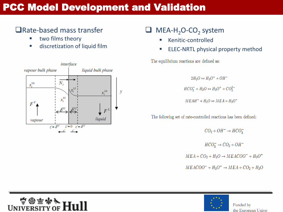
PCC Model Development and Validation
MEA-H2O-CO2 system Kenitic-controlled
ELEC-NRTL physical property method
Rate-based mass transfer two films theory discretization of liquid film
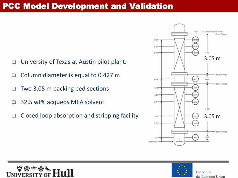
PCC Model Development and Validation
University of Texas at Austin pilot plant.
Column diameter is equal to 0.427 m
Two 3.05 m packing bed sections
32.5 wt% acqueos MEA solvent
Closed loop absorption and stripping facility
3.05 m
3.05 m
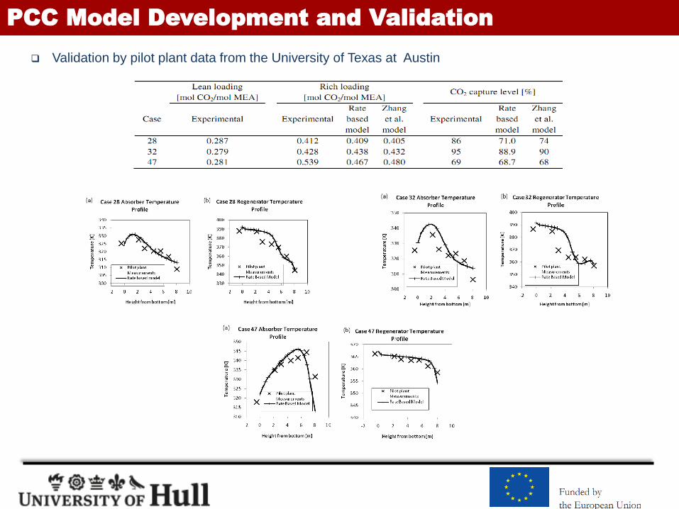
PCC Model Development and Validation
Validation by pilot plant data from the University of Texas at Austin

PCC Model Development and Validation
Scale-up to match full scale power plant with a capacity of 453MWe
Parameter Value
CO2 concentration in flue gas (mol%) 4.4
CO2 capture level (%) 90
CO2 captured (kg/s) 41.4
Columns flooding (%) 65
Lean loading (mol/mol) 0.32
Rich loading (mol/mol) 0.461
L/G (mol/mol) 1.79
Reboiler duty (kW) 188,805
Reboiler duty (GJ/tonne CO2) 4.56
Lean solvent MEA concentration (wt%) 32.5
Lean solvent temperature (K) 303.15
Absorber columns pressure (bar) 1
Absorber columns pressure loss (bar) 0.069
Absorber columns packing IMTP no. 40
Absorber columns packing height (m) 25
Absorber columns cross-section area (m2) 307.91
Regenerator column pressure (bar) 2.1
Regenerator column pressure loss (bar) 0.01355
Regenerator column packing Flexipack 1Y
Regenerator column packing height (m) 15
Regenerator column cross-section area (m2) 81.71

Supersonic shock wave compression
supersonic shock wave compression technology (Ramgen Power Systems Ltd., 2008)
– only needs 2 stages of compression (VS. 5 to 8 stages for the conventional multi-stage approach)
– 50% potential capital cost saving (Ciferno et al, 2009)
– the discharge temperature : 220oC-240oC (VS. 70oC-90oC for conventional multi-stages)
(Ramgen Power Systems Ltd., 2008)
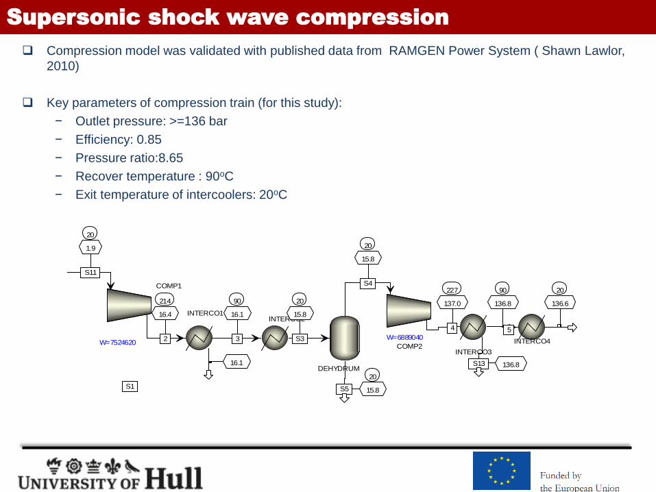
Supersonic shock wave compression
Compression model was validated with published data from RAMGEN Power System ( Shawn Lawlor,
2010)
Key parameters of compression train (for this study):
− Outlet pressure: >=136 bar
− Efficiency: 0.85
− Pressure ratio:8.65
− Recover temperature : 90oC
− Exit temperature of intercoolers: 20oC
COMP1
W=7524620COMP2
W=6889040
DEHYDRUM
Q=-0
INTERCO1
Q=-5197180
INTERCO2
Q=-3169400
INTERCO3
Q=-8303780
INTERCO4
Q=-8707680
214
16.4
2
90
16.1
3
227
137.0
4
90
136.8
5
16.1
S1
20
136.6
S2
20
15.8
S3
20
15.8
S4
20
15.8S5
136.8S13
20
1.9
S11
CCGT Integrated with PCC
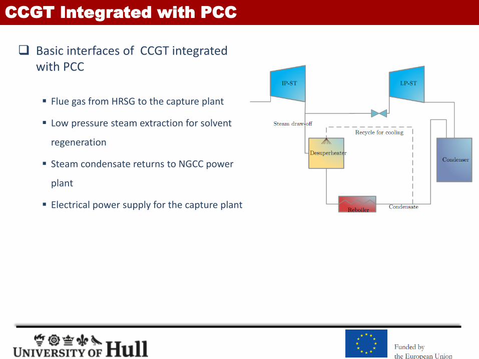
Basic interfaces of CCGT integrated with PCC
Flue gas from HRSG to the capture plant
Low pressure steam extraction for solvent
regeneration
Steam condensate returns to NGCC power
plant
Electrical power supply for the capture plant

CCGT Integrated with PCC
NGCC without
CO2 capture
NGCC with
CO2 capture
Gas turbine power output (MWel) 295.03 295.03
Steam turbine power output (MWel) 170.71 113.56
Power island auxiliary power consumption (MWel) 11.69 9.7
CO2 capture level (%) – 90
CO2 captured (kg/s) – 41.4
CO2 compression power consumption (MWel) – 15.73
Mechanical power consumption in capture
process (MWel)– 4.24
Desorber reboiler duty (MW th) – 188.8
Steam extracted for reboiler (kg/s) – 76.39
Specific reboiler duty (MJth/kg CO2) – 4.56
Net plant power output (MWel) 453.872 378.92
Net plant efficiency (%, fuel lower heating value) 58.74 49.04
Efficiency decrease(%-points) compared with
reference case– 9.70

CCGT Integrated with PCC
Exhaust gas recirculation (EGR)
The flow rate of flue gas going to the capture plant reduces 38%
CO2 concentration increase to 7.3 mol% from 4.4 mol%
The vent O2 in flue gas decease to 6.6 mol% from 11.4 mol%

NGCC Integrated with PCC
Parameter without EGR with EGR
CO2 concentration in flue gas (mol%) 4.4 7.32
CO2 capture level (%) 90 90
CO2 captured (kg/s) 41.4 40.9
Columns flooding (%) 65 65
Lean loading (mol/mol) 0.32 0.32
Rich loading (mol/mol) 0.461 0.472
L/G (mol/mol) 1.79 2.71
Reboiler duty (kW) 188,805 176,227
Reboiler duty (GJ/tonne CO2) 4.56 4.31
Lean solvent MEA concentration (wt%) 32.5 32.5
Lean solvent temperature (K) 303.15 303.15
Absorber columns pressure (bar) 1 1
Absorber columns pressure loss (bar) 0.069 0.054
Absorber columns cross-section area (m2) 307.91 216.42
Regenerator column pressure (bar) 2.1 2.1
Regenerator column pressure loss (bar) 0.01355 0.01344
Regenerator column cross-section area (m2) 81.71 75.43

CCGT Integrated with PCC
HRSG
Gas Turbine
Steam Turbine
CompressionPretreat Capture
Case Study
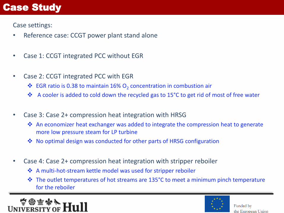
Case settings:
• Reference case: CCGT power plant stand alone
• Case 1: CCGT integrated PCC without EGR
• Case 2: CCGT integrated PCC with EGR
EGR ratio is 0.38 to maintain 16% O2 concentration in combustion air
A cooler is added to cold down the recycled gas to 15°C to get rid of most of free water
• Case 3: Case 2+ compression heat integration with HRSG
An economizer heat exchanger was added to integrate the compression heat to generate more low pressure steam for LP turbine
No optimal design was conducted for other parts of HRSG configuration
• Case 4: Case 2+ compression heat integration with stripper reboiler
A multi-hot-stream kettle model was used for stripper reboiler
The outlet temperatures of hot streams are 135°C to meet a minimum pinch temperature for the reboiler

CCGT Integrated with PCC
HRSG
Gas Turbine
Steam Turbine
CompressionPretreat Capture
Case 1 Case 2
Case 3
Case 4

Results
Description Reference Case 1 Case 2 Case 3 Case 4
NGCC NGCC +PCC NGCC +PCC NGCC +PCC NGCC +PCC
EGR without EGR without EGR with EGR with EGR with EGR
Compresion heat integration without without without with HRSG
with stripper
reboiler
Gas turbine power output (MWel) 295.03 295.03 294.64 294.64 294.64
Steam turbine power output (MWel) 170.71 113.56 117.69 120.14 121.85
Power island auxiliary power consumption (MWel) 11.69 9.7 9.7 9.7 9.7
CO2 compression power consumption (MWel) – 14.8 14.8 14.8 14.8
Mechanical power consumption in capture
process (MWel)– 4.24 2.035 2.035 2.035
Desorber reboiler duty (MW th) – 188.8 176.2 176.2 176.2
Steam extracted for reboiler (kg/s) – 76.39 71.06 71.06 65.50
CO2 captured (kg/s) – 41.4 41.4 41.4 41.4
Specific reboiler duty (MJth/kg CO2) – 4.56 4.31 4.31 4.31
Net plant power output (MWel) 453.872 379.85 385.795 388.245 389.955
Net plant efficiency (%, fuel lower heating value) 58.74 49.16 49.93 50.25 50.47
Efficiency decrease(%-points) compared with
reference case– 9.58 8.81 8.49 8.27
Overall efficiency improvement(%-points)
compared with case 1– – 0.77 1.09 1.31
Results
Summary
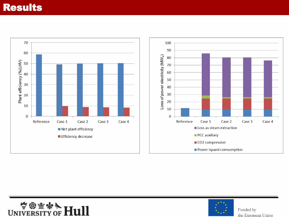
The efficiency (LHV) deceases to 49.16 % from 58.74% for conventional capture plant (Case 1):
~7.40% points for steam extraction for solvent regeneration
~0.55% points for capture plant auxiliary power consumption
~1.92% points for CO2 compression
EGR has a lower CAPEX investment because of smaller cross-section area of
the absorber (216.42m2 VS 303.15m2 28.6% reduction)
the stripper (75.43m2 VS 81.71m2 7.69% reduction)
EGR has 0.77% points efficiency improvement (Case 2 VS Case 1) because of:
7% lower steam consumption
52% blower power consumption
A litter lower solvent pumps power consumption

Summary
Compression heat integration with HRSG has 0.32% points efficiency improvement (Case 3 VS Case 2). Optimal design of HSRG configuration combining compression heat could help to achieve more efficiency improvement for Case 3.
Compression heat integration with stripper reboiler achieves 0.54% points efficiency improvement (Case 4 VS Case 2). The return temperature of the stream from compression train is 135°C (in Case 4) after is introduced to heat the reboiler, which provide the potentials to do more integration.
In a summary, CCGT with EGR integrated with PCC and supersonic shock wave compression with compression heat integration into main process could be the future direction of carbon capture deployment for CCGT power plant

Reference
• Canepa, R., Wang, M., Biliyok, C. & Satta, A. (2013), "Thermodynamic analysis of combined cycle gas turbine power plant with post-combustion CO2 capture and exhaust gas recirculation." Proceedings of the Institution of Mechanical Engineers, Part E: Journal of Process Mechanical Engineering, Vol. 227, No.2: pp. 89-105.
• Ciferno, J. P., Fout, T. E., Jones, A. P. & Murphy, J. T. (2009), "Capturing carbon from existing coal-fired power plants." Chemical Engineering Progress, Vol. 105, No.4: pp. 33-41.
• IEA (2012), "Energy Technology Perspectives 2012," Paris, International Energy Agency.• Karimi, M., Hillestad, M. & Svendsen, H. F. (2012), "Natural Gas Combined Cycle Power Plant
Integrated to Capture Plant." Energy & Fuels, Vol. 26, No.3: pp. 1805-1813.• Lawlor, S. (2010), CO2 Compression Using Supersonic Shock Wave Technology. Ramgen Power
Systems.• Marchioro Ystad, P. A., Lakew, A. A. & Bolland, O. (2013), "Integration of low-temperature
transcritical CO2 Rankine cycle in natural gas-fired combined cycle (NGCC) with post-combustion CO2 capture." International Journal of Greenhouse Gas Control, Vol. 12, No.0: pp. 213-219.
• Witkowski, A. & Majkut, M. (2012), "The impact of CO2 compression systems on the compressor power required for a pulverized coal-fired power plant in post-combustion carbon dioxide sequestration." Archive of Mechanical Engineering, Vol. 59, No.3: pp. 343-360.
• ETH Zurich. "Climate Change: Halving Carbon Dioxide Emissions By 2050 Could Stabilize Global Warming." ScienceDaily. ScienceDaily, 4 May 2009. <www.sciencedaily.com/releases/2009/05/090502092019.htm>.
Acknowledgement
EU FP7 Marie Curie IRSES (PIRSES-GA-2013-612230)
2013 China-Europe SMEs energy saving and carbon reduction research project (No.SQ2013ZOA100002)
Water and Energy Workshop