heat partition effect on cutting tool morphology in
TRANSCRIPT

326
ISSN 13921207. MECHANIKA. 2019 Volume 25(4): 326334
Heat Partition Effect on Cutting Tool Morphology in Orthogonal Metal
Cutting Using Finite Element Method
Kamuran Kamil YEŞİLKAYA*, Kemal YAMAN** *The Scientific and Technical Research Council of Turkey, Defense Industries Research and Development Institute
(TÜBİTAK-SAGE), Ankara, 06261, Turkey. E-mail: [email protected]
**The Scientific and Technical Research Council of Turkey, Defense Industries Research and Development Institute
(TÜBİTAK-SAGE), Ankara, 06261, Turkey. E-mail: [email protected]
http://dx.doi.org/10.5755/j01.mech.25.4.22745
1. Introduction
Metal cutting process is a removal of a layer of
metal, which is called the chip, by a cutting tool. The
heavy industries such as automotive, aerospace, construc-
tion, etc. often employ the metal cutting processes in their
manufacturing activities. In the engineering field, the word
“machining” is used to refer to material removal processes.
These processes are classified into several groups such as
turning, milling, drilling, and so on. This study uses turn-
ing operations which are widely employed in manufactur-
ing industry. The metal cutting process consists of thermal
and mechanical operations. Plastic deformation taking
place within the workpiece material and frictional interac-
tions between the cutting tool and the chip cause heat gen-
eration during the cutting process. One assumption is used
at this point that nearly all the energy in the cutting process
transforms into heat. The heat generated leads to an in-
crease in tool temperature in the machining process. The
elevated temperature affects the microstructure of the tool
material as well as the workpiece material.
Most importantly, this results in rapid tool wear.
As a result, machined part quality and tool life is severely
affected. Tool life is considered as an important factor af-
fecting the cost of the metal cutting process. Manufacturers
try to avoid having many tool replacements during the cut-
ting process. To avoid this, tool wear mechanisms have to
be analysed and preventive measures have to be taken. In
the machining processes, the cost of the process and the
quality of the work has to be considered carefully. To be
able to manage this, a way of cost reduction is investigated
while maintaining the overall quality at higher levels.
Therefore, temperature distribution in metal cutting pro-
cesses requires to be fully identified so that the cutting
process would be properly accomplished. In any metal
cutting operation, the cutting instrument interacts with the
workpiece material and isolates the chip from the work-
piece material by breaking the bonds at the shear plane.
Thus, heat is produced inside the workpiece material. It is
important to find the partition and distribution of the heat
sources in such orthogonal machining operations [1].
Temperatures in the orthogonal machining opera-
tions have an influence on machining performance. The
microstructure of the workpiece material is modified by
temperature and hence the workpiece material becomes
ductile and cutting forces decrease. At the tool-chip inter-
face, thermal interactions have a major effect on tool life
due to the fact that high temperature values cause the sof-
tening of the cutting tool and thus trigger tool wear. A
study in terms of temperature distribution and heat parti-
tion gives rise to the necessity of the tool coatings in such
metal cutting processes.
Modelling techniques have been used to under-
stand temperature distribution and heat partition in metal
cutting operations. Main modelling techniques are analyti-
cal technique and numerical technique, i.e. Finite Element
Modelling (FEM). These are often used with an experi-
mental study to validate the results. Finite element models
have gained acceptance to discover the temperature distri-
bution characteristic in orthogonal machining operations.
The reason is that the FEM gives an opportunity to find
thermal parameters such as temperature, heat flux, et cetera
without establishing a real cutting operation or doing a
series of experiments which can be considered to causing
cost and time.
Akbar et al. [2] conducted a number of experi-
ments to find the variety of cutting forces in orthogonal
machining by using uncoated and coated cutting tools.
There is a decrease in cutting forces between the cutting
speeds of 100 m/min and 395 m/min, a slight increase in
cutting forces between the cutting speeds of 395 m/min
and 565 m/min, and finally a fall in cutting forces in the
HSM region for TiN-coated tools. Several analytical mod-
els were studied for a steady-state temperature solution in
the cutting process. Two of these models are suggested by
Akbar et al. are of Komanduri and Hou's [3-5] and Yong et
al's models. [6]. In these models, boundary conditions are
applied as heat sources in the primary and secondary de-
formation zones. In addition, it is assumed that most of the
deformation energy during the cutting process transforms
into heat. Abukhshim’s [7] and Mativenga [8] presents an
analysis of the contact length between the cutting tool and
the chip, and tool wear for uncoated tungsten-based ce-
mented carbide tools. A number of experiments were con-
ducted for dry high-speed turning of EN19 alloy steel us-
ing the cutting speeds of between 200 and 1200 m/min, the
feed rates of 0.14 and 0.2 mm/rev, and a constant depth of
cut of 0.1 mm. The aim of Abukhshim’s study was to set
up a connection between the cutting speed and the contact
length in such cutting operations. Abukhshim’s results
showed that the contact length changes relative to the con-
tact at the interface between the cutting tool and the chip.
The cutting speed majorly affected the contact phenomena,
which was different for conventional and high-speed ma-
chining conditions. It can be mentioned that the mathemat-
ical models for the calculation of contact length were quan-
titatively in conflict with the experimental results for high
speed turning.

327
A cutting process includes three regions of heat
generation in the process: shearing plane zone, the inter-
face between the tool and the chip, and the surface between
the flank face of the cutting tool and the workpiece [9]. At
the interface between the cutting tool and the chip, plastic
deformation takes place while generating the chip by
breaking the bonds between atoms along the shearing
plane. After the formation of the chip, it flows along the
rake face of the cutting tool. As a result, heat is generated
and transferred into the cutting tool. In order to achieve the
contact length value in orthogonal cutting process, various
mathematical models have been developed in combination
with some experimental work [10]. With the help of these
models, it is possible that the process parameters of chip
thickness and rake angle are qualitatively estimated and the
relationship between these parameters and the contact
length is then easily assumed [11]. However, quantitative
differences between the results of different models are ex-
perienced. In these mathematical models, the cutting speed
was not taken into consideration to address the contact
length. For this reason, this study investigated the effect of
the cutting speed on the contact length for the speed range
of 200-1200 m/min.
Coated cutting tools are likely to improve tool
performance compared to uncoated tools. Coatings can
play a major role in the prevention of diffusion process at
high temperatures in high speed machining. Moreover,
there are different coating types. It was mentioned that
physical vapor deposited (PVD) coatings are less affected
by chipping in the cutting process than the chemical vapor
deposited (CVD) coatings [12-13]. This makes the PVD
coatings preferable for high speed cutting applications.
Besides, coated cutting tools experience reduced cutting
forces and improved wear resistance which improve tool
life [14]. In a study by Trigger et al. [15], 12 % of the heat
generated was estimated to be entering the cutting tool.
Stephenson et al. [16] found that 15% of the heat generated
transferred into the cutting tool whereas the heat fraction
value stated by Komanduri et al. [4] was 10 %. Blok`s en-
ergy partition analysis [17] is often employed as the analyt-
ical model for thermal analyses of metal cutting operations.
Numerical approaches for metal cutting opera-
tions enable manufacturers or researchers to model the
process and solve it in an economical way compared to
tests in the experimental cutting process. The process can
be modelled by using the geometrical and material features
of the cutting tool together with the cutting parameters [18-
21].
In the thermal effect studies performed in the lit-
erature, both cutting tool, workpiece material and cutting
medium are modelled. This real-time finite element analy-
sis takes more and more times. Whereas in this study, only
the cutting tool is modelled and a significant reduction in
processing time is obtained. Therefore, the main purpose
here is to generate the correct finite element model which
is ready to use when deciding the tool coating thickness
required for related machining operations [22]. First, we
focused on the physical background of the heat transfer
mechanism of orthogonal cutting.
1.1. Heat generation
The three deformation zones, i.e. primary, sec-
ondary, and tertiary (See Fig. 1 in Section 1.2), cause the
generation of heat in machining. In terms of heat transfer
into the cutting tool, the major effect comes from the sec-
ondary deformation zone. It is expected that the rake face
of the cutting tool prevents heat from entering the cutting
tool. Moreover, the speed of the process is another im-
portant factor in the evaluation of the heat partition analy-
sis. Heat generation takes place in three deformation zones;
primary, secondary, and tertiary. Primary deformation zone
is formed due to the plastic deformation of the workpiece
material. Secondary deformation zone is a result of the
interaction between the tool and the chip [3]. After the
formation of chip, it flows along the rake face of the tool
and this generates heat in this region. Tertiary deformation
zone represents rubbing between the processed workpiece
surface and the tool flank face. The Power required for
machining is given by;
. ,c c
P F V (1)
where: Pc is cutting power, (W); Fc is cutting force (N) and
V is cutting velocity (m/s). If it is assumed that all cutting
power transforms into heat, then total heat is given by:
. .c
Q F V (2)
Friction between the tool and the chip causes the
generation of heat in the secondary deformation zone
which is given by:
. ,f ch
Q F V (3)
where: heat generated in the second. def. zone (W) is de-
noted by Qf; frictional force (N) is denoted by Fγ and chip
velocity (m/s) is denoted by Vch.
/ ,ch c h
V V (4)
where: cutting speed (m/s) is denoted by Vc and chip com-
pression ratio λh, given as:
,h ch
t t (5)
here: tch is actual chip thickness (mm) and t is un-deformed
chip thickness (mm). When Eq. (4) is substituted in Eq.
(3), Eq. (6) is obtained as:
. / ,f h
Q F V (6)
. . ,c s
F F sin F cos (7)
where: Fs is feed force (N) and α is tool rake angle.
1.2. Heat partition
Heat generated in the process transmits into the
cutting tool, the chip, and the workpiece. This partition is
shown in Fig. 1. The primary and secondary deformation
zones lead to an increase of the cutting tool temperature
and influence heat interaction at the interface between the
cutting tool and the chip. In the primary deformation zone,
local heat first transfers into the chip and then into the cut-

328
ting tool due to the tool-chip interaction. As a conse-
quence, both primary and secondary deformation zones
have influence on the temperature distribution of the tool
rake face [23, 24].
Zemzemi et al. [25] characterized the friction re-
sponse between the tool and work material while dry turn-
ing of Inconel 718 with TiN coated carbide and CBN tools.
An open tribometer were employed to obtain the friction
and heat partition coefficients.
Fig. 1 Deformation zones and heat transfer mechanism
The study stated that both the friction and heat
partition coefficients decrease while cutting velocity or
contact pressure increases. From the study, the coefficient
of heat partition Rt is stated as shown below. While ex-
tracting the equation, the assumptions were accepted as
follows; heat is generated from all existing energy during
the operation and the thermal conductivity value is fixed.
/ . ,t t
R Q F V (8)
here: heat partition coefficient on tool is denoted by Rt and
heat flux on tool is denoted by Qt. This indicates the heat
flux of Rt.Qt is for tool, while the one of (1–Rt) is for
workpiece. When the heat dissipation of plastic defor-
mation of the workpiece is omitted and the existence of a
relative movement between the tool and workpiece is as-
sumed, the theoretical heat partition coefficient Rt-theo can
be calculated. A frequently employed model is specified in
Eq. (9) [25].
. .,
. . . .
t t tt
t theo
t wm t t t wm wm wm
k cR
k c k c
(9)
where: εwm is effusivity of workpiece material, εt is effusiv-
ity of tool, kt is tool material thermal conductivity coeffi-
cient, kwm is workpiece material thermal cond. coefficient,
ρt is tool material density, ρwm is workpiece material densi-
ty, ct is specific heat of tool and cwm is specific heat of
workpiece.
According to the Shaw [26], the heat partition co-
efficient for the tool:
1
1
1 1 0.754 ,t
t a T
wm
kR A N
k
(10)
here: A is depth of cut and lc is contact length between tool
and chip. Similarly, The Leowen-Shaw model [27] is de-
pended on the heat zones generated in cutting operations,
assuming the tool is sharp and with no chip breaking ge-
ometry. In expression (13), temperature rise between chip
and tool is denoted by Δθs and temperature at origin point
is denoted by θ0.
0
0.377
.0.377
c
s
wm T
t
c a c
t wm T
Ql
k NR
Ql A Ql
k k N
(13)
The model given in Eq. (13) represent the fric-
tional heat work that formed in secondary deformation
zone. On the other hand, the model includes the heat trans-
ferred from the area of sliding contact surface during the
machining.
2. Materials and method
A Dean Smith & Grace lathe machine was used to
perform experiments in Akbar et al's study [3]. The cutting
forces were quantified by a KISTLER 9121 model cutting
load cell. For the experiments, tungsten-based uncoated
cemented carbide and PVD TiN-coated tools (TCMW
16T304-ISO specification, triangular shape insert with 0.4
mm nose radius, 7° clearance angle and 3.97 mm thick-
ness) and Sandvik STGCR/L 2020K 16-ISO specification
were used. The experimental conditions are given in Table
1. In the experiments, a pre-bored workpiece of AISI/SAE-
4140 alloy steel with an external diameter of 200 mm and
2.5 mm tube thickness was processed. Eight different cut-
ting speeds, i.e. 100, 197, 314, 395, 565, 628, 785, and
880 m/min, a feed rate of 0.1 mm/rev, and a depth of cut of
2.5 mm were used [3]. To obtain the emissivity values,
uncoated and TiN-coated inserts were heated in an oven
and then their temperature values were measured by an IR
thermal imaging camera (FLIR ThermaCAM-SC3000).
The IR thermal imager was located near the machine tur-
ret, i.e. at a distance of 25 cm from the insert, and pointed
on the tool rake face. The emissivity value was adjusted
until the temperature reading of the thermal imager
matched a thermocouple reading. The average emissivity
values of 0.48 and 0.21 were found at 700°C for the un-
coated cemented carbide and TiN-coated tool inserts re-
spectively.
Table 1
Experimental conditions [3]
Items Conditions or features
Machine tool Conventional lathe (Dean Smith &
Grace) machine
Workpiece AISI/SAE 4140
Workpiece size 200 mm external diameter and
2.5 mm tube thickness
Cutting inserts TCMW16T304-5015 (UCC) and
TCMW 16T304 6620 (TiN)
Tool holder STGCR/L 2020K 16
Cutting velocity, Vc 100, 197, 314, 395, 565, 628, 785,
and 880 m/min
Feed rate, f 0.1 mm/rev
Depth of cut, a 2.5 mm
Environment Dry orthogonal machining

329
2.1. Finite element modelling
A geometrical model which consists of a cement-
ed carbide insert, a shim seat, and a tool holder has been
generated. The CAD and FE model is shown in Fig. 2, a
and Fig. 2, b respectively. The finite element mesh of the
cutting tool was generated with 18580 nodes and 12027
four-node linear tetrahedron elements.
a
b
Fig. 2 (a) CAD model and (b) Meshed model for TiN-
coated (3 μm) cutting tool
TiN-coated cutting tools were generated in
ABAQUS with the coating thickness values of 3 and 10
μm which are applicable minimum and maximum coating
thicknesses for the most convenient mesh size and analysis
time. The CAD model of the TiN-coated (3 μm) cutting
tool is shown in Fig. 2 the material properties of tool hold-
er, shim and TiN coated tool are stated in Table 2.
Table 2
Material properties for tool holder, shim and tools (UCC-
TiN coated) [3]
Component Tool holder Substrate
and shim
TiN-coated
tool tip
Material AISI 1045 UCC TiN
E Young’s
Modulus,
GPa 207 534 250
υ Poisson’s
ratio 0.3 0.22 0.25
ρ Density,
kg/m3 7844 11900 5420
κ
Thermal
Cond. @
given
Temp. °C,
W/m.K
100°C
400°C
700°C
1000°C
50.7
41.9 30.1
26.8
100°C
400°C 700°C
1000°C
40.2
52.8 65.4
78
100
400 700
1000
21
22.5 24.3
26
C
Specific
heat @
given
Temp.°C,
J/kg.K
100°C 400°C
700°C
1000°C
470.4 621.6
772.8
924
100 °C 400 °C
700 °C
1000 °C
346 382
418
454
100 400
700
1000
703 801.2
846.4
859.3
Point for matchingUniform heat flux
Fig. 3 Applied heat flux on the tool tip
The following boundary conditions and assump-
tions were used and the nomenclature of boundary condi-
tions are given in Fig. 3:
A plane heat source at the interface between the
cutting tool and the chip was assumed.
The initial model temperature was taken as 25°C.
The rear end surface of the tool holder was sub-
jected to ambient conditions.
The free surfaces of the insert and the holder were
assigned a heat transfer coefficient (h) value of 20
(W/m2K)
The thermal analysis was steady-state.
There was no rubbing action between the work-
piece and the flank face of the tool which was
modelled as a rigid body.
Tool wear was not considered in the analysis.
The contact area between the tool and the chip
was constant.
The flank face had no effect on the fraction of
heat entering the tool
Heat generation was only associated with the rake
face of the tool.
3. Results and discussion
Two different cutting tools have been investigated
by using FEM, which were tungsten-based uncoated ce-
mented carbide and TiN-coated tungsten-based cemented
carbide inserts. Steady-state and transient temperature dis-
tributions at the tip of the cutting tool are shown in Fig. 4
and Fig. 5 for conventional machining and HSM respec-
tively for uncoated cemented carbide (UCC) tool.
a
b
Fig. 4 Temperature distribution of UCC in conventional
machining (a) steady-state (12.5% heat flux applied,
Tmax=699.5 °C, Area=0.3 mm2) (b) transient analysis
(Tmax=698.8 °C)

330
a
b
Fig. 5 Temperature distribution of UCC in HSM (a) steady
state (5.5% heat flux applied, Tmax=1064°C,
Area=0.1 mm2), (b) transient analysis (Tmax=1083)
In addition, simulations for the transient heat
transfer analysis for 6 seconds were completed for UCC
and TiN tool in HSM respectively under constant heat flux
regime (12.5%). In the transient thermal analysis, heat
transfer process takes some time to obtain temperature
values of the point which were obtained from the steady-
state analysis. The plots of the transient thermal analysis
for the comparison of UCC and TiN tools are given in
Fig. 6. The transient analysis was kept running for a period
of time so that the temperature values of the steady-state
analysis were reached. For HSM, the transient analysis was
run for 6 seconds.
In this study, however, only thermal modelling of
the cutting was taken into consideration. It was assumed
that the temperatures values reach invariable values after
the transient period of time. In conventional machining, the
heat fraction value was 12.5% which is higher than the
value in HSM. This is related to the low cutting speed
which led to having more contact time and larger contact
area. In high speed machining, 5.5% of the heat generated
at the interface between the cutting tool and the chip, i.e.
secondary deformation zone, passed into the tool due to
short time of contact and heat removal mainly by the chip.
On the other hand, higher temperature values were experi-
enced in the HSM operation because of higher cutting
speeds although the amount of heat flux entering the cut-
ting tool were less than the conventional machining opera-
tion. This is connected to the fact that the smaller contact
area found in high speed machining led to a limited
amount of heat flowing into the cutting tool.
0
100
200
300
400
500
600
0.1 1.0 2.3 3.3 4.1 4.8 5.4 5.9
Tra
nsi
ent
tem
pera
ture
[ºC
]
Time [s]
UCC
TiN
Fig. 6 UCC and TiN tool temperature comparison against
time in transient thermal analysis for HSM region
Temperature values reduce when the TiN-coating
film was applied on the tungsten-based uncoated cemented
carbide insert. This reduction amount changes in relation to
the machining mode and the coating thickness. For con-
ventional machining, the temperature reductions of 15.6°C
and 27.7°C were obtained for the coating thickness values
of 3 and 10 μm respectively. As it can be seen from Ta-
ble 3, the temperature reduction values are higher for
HSM, which are 22°C and 36°C for the coating thickness
values of 3 and 10 μm respectively. The temperature re-
ductions are achieved as a result of the decrease in the con-
tact length and thus the contact area [3]. A higher tempera-
ture decrease in HSM occurs due to higher cutting speeds
which lead to shorter time of contact, smaller contact area,
and more heat removal by the chip compared to conven-
tional machining.
Table 3
FE results for UCC and TiN-coated tool
Tool conditions Conventional
machining HSM
Tool
Coating
Thickness,
μm
Max.
Temp.
Tmax,
°C
Temp.
Reduction,
°C
Max.
Temp.
Tmax,
°C
Temp.
Reduc.,
°C
TiN 3 683.2 15.6 1061 22
TiN 10 671.1 27.7 1047 36
UCC 698.8 - 1083 -
A higher temperature decrease in HSM takes
place because of higher cutting speeds which lead to short-
er time of contact, smaller contact area, and more heat re-
moval by the chip compared to conventional machining.
The results revealed that the TiN-coated cutting tool expe-
rienced lower temperature values than the UCC cutting
tool. This is related to the smaller conductivity value of the
TiN-coated tool which generates a thermal barrier effect
against the heat flowing into the cutting tool. The thermal
conductivity of the coating film is expected to alter heat
partitions for the cutting tool and the chip. It is assumed
that lower thermal conductivity brings about smaller heat
partition value for the cutting tool. In terms of the coated
tools, higher temperature reductions were obtained from
the finite element simulations for HSM in comparison to

331
those for conventional machining. In HSM, the contact
area between the tool and the chip is found to be smaller
than the contact area in conventional machining [3]. This
leads to a decrease in the amount of heat transferred into
the cutting tool for HSM and hence lower temperature val-
ues for the cutting tool are experienced. In Figs. 7 and 8,
Temperature distributions of TiN-coated cutting tools are
given for 10 μm coating thicknesses.
For higher cutting speeds, heat partition increases
for uncoated cemented carbide tools while a decreasing
trend continues for TiN-coated tools due to reduction in
contact area. Between the cutting speed range of 100–
395 m/min, heat partition decreases due to reduced contact
area (Fig. 9). Above the cutting speed of 395 m/min, which
is the high-speed region, contact area increases for uncoat-
ed cemented carbide tools (Fig. 10). The results of finite
element analysis give close values in following graphs.
Contact area for TiN-coated tools decreases at
higher speeds (>395 m/min). Thus, the fraction of heat
transferred into the cutting tool reduces. This shows that
TiN-coated tools experience lower heat transfer compared
to uncoated tools (Fig. 10). For conventional cutting
speeds, the maximum difference in heat partition between
experimental results and FEM results is about 15% for
both tool whereas for HSM region, it is about 10% for TiN
and 50% for UCC. As can be seen, TiN coatings have a
more pronounced effect on decreasing the amount of heat
transferred into the tool in HSM region than conventional
cutting speed region.
a
b
Fig. 7 Temperature distribution of TiN-coated cutting tool
(10 μm) in conventional machining (a) steady-state
(12.5% heat flux applied, Tmax=646.1oC, Ar-
ea=0.3mm2) (b) transient analysis (Tmax=671.1oC)
a
b
Fig. 8 Temperature distribution of TiN-coated cutting tool
(10 μm) for transient analysis in HSM (a) steady-
state (5.5% heat flux applied, Tmax=978.5oC, Ar-
ea=0.1 mm2) (b) transient analysis (Tmax=1047 oC)
0
0.05
0.1
0.15
0.2
0.25
0.3
0.35
0.4
0 200 400 600 800 1000
Heat
par
titi
on c
oeff
icie
nt,
Rt
Cutting velocity [m/min], Vc
Experimental [4]
FEM
Curve fit
TIN Coated Tool
Fig. 9 Heat partition coefficient comparison against cutting
velocity for TiN tool both experimentally [3] and
FEM
Thermal conductivity of the tool insert defines the
amount of heat flowing into the cutting tool and the chip.
Low thermal conductivity leads to high chip temperature,
i.e. more curled chips, and hence less amount of heat trans-
ferring into the cutting tool. As a result, the contact length
between the cutting tool and the chip and hence cutting
tool life are affected. Fig. 11 shows heat partition, Rt com-
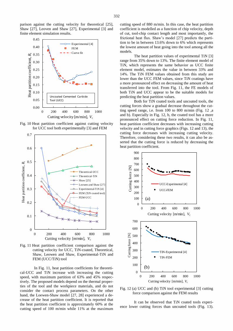
332
parison against the cutting velocity for theoretical [25],
Shaw [27], Leoven and Shaw [27], Experimental [3] and
finite element simulation results.
0.00
0.05
0.10
0.15
0.20
0.25
0.30
0.35
0.40
0.45
0 200 400 600 800 1000
Hea
t pa
rtit
ion
coef
fici
ent,
Rt
Cutting velocity [m/min], Vc
Experimental [4]
FEM
Curve fit
Uncoated Cemented Carbide Tool (UCC)
Fig. 10 Heat partition coefficient against cutting velocity
for UCC tool both experimentally [3] and FEM
0
0.1
0.2
0.3
0.4
0.5
0.6
0.7
0 200 400 600 800 1000
Hea
t p
arti
tion c
oef
fici
ent,
Rt
Cutting velocity [m/min], Vc
Theoretical-UCC
Theoretical-TiN
Shaw [25]
Leowen and Shaw [27]
Experimental-TiN [4]
FEM (TiN coated tool)
FEM-UCC
Fig. 11 Heat partition coefficient comparison against the
cutting velocity for UCC, TiN-coated, Theoretical,
Shaw, Leowen and Shaw, Experimental-TiN and
FEM (UCC/TiN) tool
In Fig. 11, heat partition coefficients for theoreti-
cal-UCC and TiN increase with increasing the cutting
speed, with maximum partition of 63% and 45% respec-
tively. The proposed models depend on the thermal proper-
ties of the tool and the workpiece materials, and do not
consider the contact process parameters. On the other
hand, the Loewen-Shaw model [27, 28] experienced a de-
crease of the heat partition coefficient. It is reported that
the heat partition coefficient is approximately 60% at the
cutting speed of 100 m/min while 11% at the maximum
cutting speed of 880 m/min. In this case, the heat partition
coefficient is modelled as a function of chip velocity, depth
of cut, tool-chip contact length and most importantly, the
frictional heat flux. Shaw’s model [27] predicts the parti-
tion to be in between 13.6% down to 6% which represents
the lowest amount of heat going into the tool among all the
models.
The heat partition values of experimental TiN [3]
range from 35% down to 13%. The finite element model of
TiN, which represents the same behavior as UCC finite
element model, estimates the value in between 33% and
14%. The TiN FEM values obtained from this study are
lower than the UCC FEM values, since TiN coatings have
a more pronounced effect on decreasing the amount of heat
transferred into the tool. From Fig. 11, the FE models of
both TiN and UCC appear to be the suitable models for
predicting the heat partition values.
Both for TiN coated tools and uncoated tools, the
cutting forces show a gradual decrease throughout the cut-
ting speed range, i.e. from 100 to 800 m/min (Fig. 12 ,a
and b). Especially in Fig. 12, b, the coated tool has a more
pronounced effect on cutting force reduction. In Fig. 11,
heat partition coefficient decreases with increasing cutting
velocity and in cutting force graphics (Figs. 12 and 13), the
cutting force decreases with increasing cutting velocity.
Therefore, considering these two results, it can also be as-
serted that the cutting force is reduced by decreasing the
heat partition coefficient.
0
100
200
300
400
500
600
700
800
900
0 200 400 600 800 1000
Cu
ttin
g f
orc
e [
N]
Cutting velocity [m/min], Vc
UCC-Experimental [4]
UCC-FEM
(a)
0
100
200
300
400
500
600
700
0 200 400 600 800 1000
Cutt
ing
forc
e [N
]
Cutting velocity [m/min], Vc
TiN-Experimental [4]
TiN-FEM
(b)
Fig. 12 (a) UCC and (b) TiN tool experimental [3] cutting
force comparison against the FEM results
It can be observed that TiN coated tools experi-
ence lower cutting forces than uncoated tools (Fig. 13).
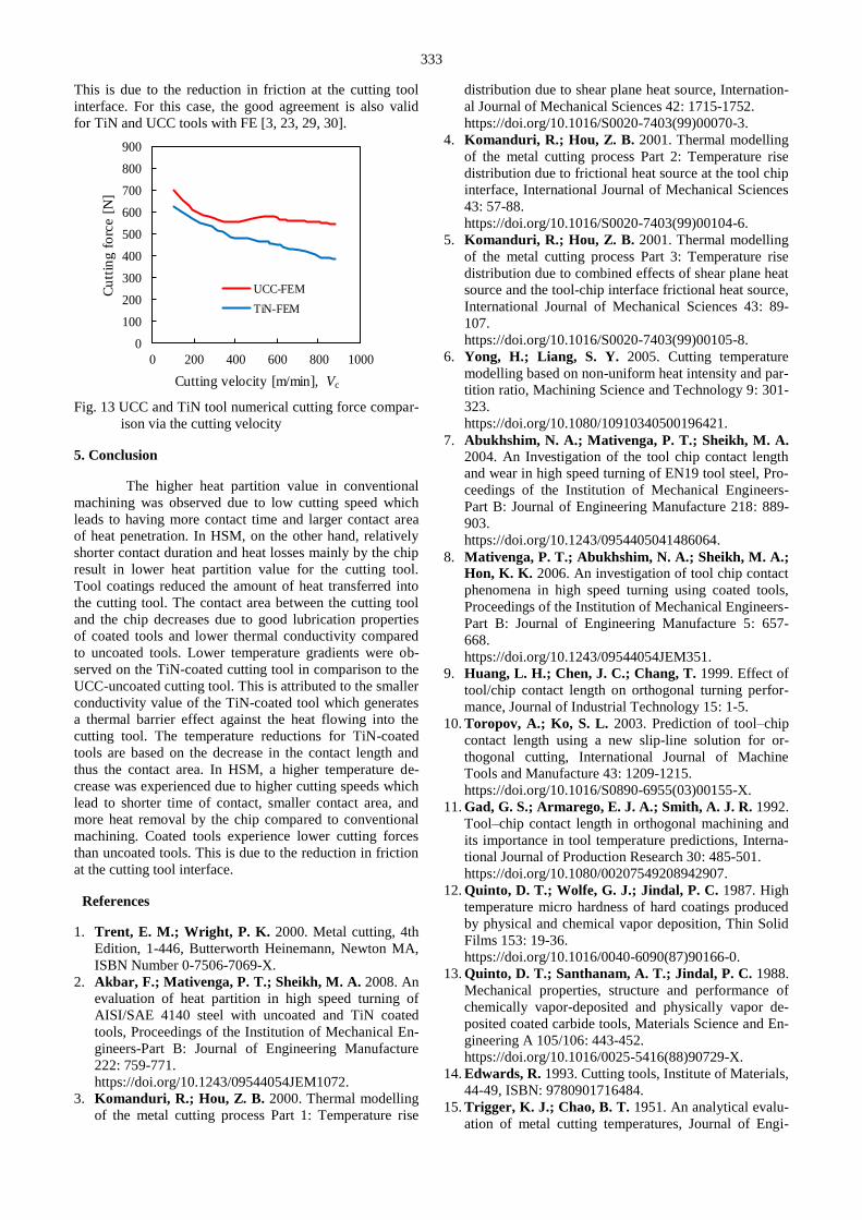
333
This is due to the reduction in friction at the cutting tool
interface. For this case, the good agreement is also valid
for TiN and UCC tools with FE [3, 23, 29, 30].
0
100
200
300
400
500
600
700
800
900
0 200 400 600 800 1000
Cu
ttin
g f
orc
e [
N]
Cutting velocity [m/min], Vc
UCC-FEM
TiN-FEM
Fig. 13 UCC and TiN tool numerical cutting force compar-
ison via the cutting velocity
5. Conclusion
The higher heat partition value in conventional
machining was observed due to low cutting speed which
leads to having more contact time and larger contact area
of heat penetration. In HSM, on the other hand, relatively
shorter contact duration and heat losses mainly by the chip
result in lower heat partition value for the cutting tool.
Tool coatings reduced the amount of heat transferred into
the cutting tool. The contact area between the cutting tool
and the chip decreases due to good lubrication properties
of coated tools and lower thermal conductivity compared
to uncoated tools. Lower temperature gradients were ob-
served on the TiN-coated cutting tool in comparison to the
UCC-uncoated cutting tool. This is attributed to the smaller
conductivity value of the TiN-coated tool which generates
a thermal barrier effect against the heat flowing into the
cutting tool. The temperature reductions for TiN-coated
tools are based on the decrease in the contact length and
thus the contact area. In HSM, a higher temperature de-
crease was experienced due to higher cutting speeds which
lead to shorter time of contact, smaller contact area, and
more heat removal by the chip compared to conventional
machining. Coated tools experience lower cutting forces
than uncoated tools. This is due to the reduction in friction
at the cutting tool interface.
References
1. Trent, E. M.; Wright, P. K. 2000. Metal cutting, 4th
Edition, 1-446, Butterworth Heinemann, Newton MA,
ISBN Number 0-7506-7069-X.
2. Akbar, F.; Mativenga, P. T.; Sheikh, M. A. 2008. An
evaluation of heat partition in high speed turning of
AISI/SAE 4140 steel with uncoated and TiN coated
tools, Proceedings of the Institution of Mechanical En-
gineers-Part B: Journal of Engineering Manufacture
222: 759-771.
https://doi.org/10.1243/09544054JEM1072.
3. Komanduri, R.; Hou, Z. B. 2000. Thermal modelling
of the metal cutting process Part 1: Temperature rise
distribution due to shear plane heat source, Internation-
al Journal of Mechanical Sciences 42: 1715-1752.
https://doi.org/10.1016/S0020-7403(99)00070-3.
4. Komanduri, R.; Hou, Z. B. 2001. Thermal modelling
of the metal cutting process Part 2: Temperature rise
distribution due to frictional heat source at the tool chip
interface, International Journal of Mechanical Sciences
43: 57-88.
https://doi.org/10.1016/S0020-7403(99)00104-6.
5. Komanduri, R.; Hou, Z. B. 2001. Thermal modelling
of the metal cutting process Part 3: Temperature rise
distribution due to combined effects of shear plane heat
source and the tool-chip interface frictional heat source,
International Journal of Mechanical Sciences 43: 89-
107.
https://doi.org/10.1016/S0020-7403(99)00105-8.
6. Yong, H.; Liang, S. Y. 2005. Cutting temperature
modelling based on non-uniform heat intensity and par-
tition ratio, Machining Science and Technology 9: 301-
323.
https://doi.org/10.1080/10910340500196421.
7. Abukhshim, N. A.; Mativenga, P. T.; Sheikh, M. A. 2004. An Investigation of the tool chip contact length
and wear in high speed turning of EN19 tool steel, Pro-
ceedings of the Institution of Mechanical Engineers-
Part B: Journal of Engineering Manufacture 218: 889-
903.
https://doi.org/10.1243/0954405041486064.
8. Mativenga, P. T.; Abukhshim, N. A.; Sheikh, M. A.;
Hon, K. K. 2006. An investigation of tool chip contact
phenomena in high speed turning using coated tools,
Proceedings of the Institution of Mechanical Engineers-
Part B: Journal of Engineering Manufacture 5: 657-
668.
https://doi.org/10.1243/09544054JEM351.
9. Huang, L. H.; Chen, J. C.; Chang, T. 1999. Effect of
tool/chip contact length on orthogonal turning perfor-
mance, Journal of Industrial Technology 15: 1-5.
10. Toropov, A.; Ko, S. L. 2003. Prediction of tool–chip
contact length using a new slip-line solution for or-
thogonal cutting, International Journal of Machine
Tools and Manufacture 43: 1209-1215.
https://doi.org/10.1016/S0890-6955(03)00155-X.
11. Gad, G. S.; Armarego, E. J. A.; Smith, A. J. R. 1992.
Tool–chip contact length in orthogonal machining and
its importance in tool temperature predictions, Interna-
tional Journal of Production Research 30: 485-501.
https://doi.org/10.1080/00207549208942907.
12. Quinto, D. T.; Wolfe, G. J.; Jindal, P. C. 1987. High
temperature micro hardness of hard coatings produced
by physical and chemical vapor deposition, Thin Solid
Films 153: 19-36.
https://doi.org/10.1016/0040-6090(87)90166-0.
13. Quinto, D. T.; Santhanam, A. T.; Jindal, P. C. 1988.
Mechanical properties, structure and performance of
chemically vapor-deposited and physically vapor de-
posited coated carbide tools, Materials Science and En-
gineering A 105/106: 443-452.
https://doi.org/10.1016/0025-5416(88)90729-X.
14. Edwards, R. 1993. Cutting tools, Institute of Materials,
44-49, ISBN: 9780901716484.
15. Trigger, K. J.; Chao, B. T. 1951. An analytical evalu-
ation of metal cutting temperatures, Journal of Engi-

334
neering for Industry-Transactions of the ASME 73: 57-
60.
16. Stephenson, D. A.; Ali, A. 1992. Tool temperatures in
interrupted metal cutting, Journal of Engineering for
Industry-Transactions of the ASME 14: 127-136.
https://doi:10.1115/1.2899765.
17. Blok, H. 1938. Theoretical study of temperature rises
at surfaces of actual contact under oiliness lubricating
conditions, Proceedings of the General Discussion on
Lubrication and Lubricants. The Institution of Mechan-
ical Engineers, London, 222-235.
18. König, W.; Fritsch, R.; Kammermeier, D. 1992.
New approaches to characterizing the performance of
coated cutting tools, Annals of the CIRP 41: 49-54.
https://doi.org/10.1016/S0007-8506(07)61150-0.
19. Rech, J.; Djouadi, M. A.; Picot, J. 2001. Wear re-
sistance of coatings in high speed gear hobbing, Wear
250: 45-53.
https://doi.org/10.1016/S0043-1648(01)00629-9.
20. Ng, E. G.; Aspinwall, D. K.; Brazil, D.; Monaghan,
J. 1999. Modelling of temperature and forces when or-
thogonally machining hardened steel, International
Journal of Machine Tools & Manufacture 39: 885-903.
https://doi.org/10.1016/S0890-6955(98)00077-7.
21. Ghani, M. U.; Abukhshim, N. A.; Sheikh, M. A. 2008. An investigation of heat partition and tool wear
in hard turning of H13 tool steel with CBN cutting
tools, International Journal of Advanced Manufacturing
Technology 39: 874-888.
https://doi.org/10.1007/s00170-007-1282-7.
22. Yesilkaya K.K. 2010. A numerical investigation of
temperature distribution and heat partition in orthogo-
nal metal cutting processes, ASME 2010 International
Manufacturing Science and Engineering Conference
(MSEC 2010), 12-15 October, Erie, PA, USA.
23. Fahad, M.; Mativenga, T.; Sheikh, M. A. 2013. On
the contribution of primary deformation zone-generated
chip temperature to heat partition in machining, Inter-
national Journal of Advanced Manufacturing Technol-
ogy 68: 99–110.
https://doi.org/10.1007/s00170-012-4711-1.
24. Abukhshim, N. A.; Mativenga, P. T.; Sheikh, M. A. 2005. Investigation of heat partition in high speed turn-
ing of high strength alloy steel, International Journal of
Machine Tools & Manufacture 45: 1687-1695.
https://doi.org/10.1016/j.ijmachtools.2005.03.008.
25. Zemzemi, F.; Rech, J.; Salem, W.B.; Dogui, A.;
Kapsa, P. 2014. Identification of friction and heat par-
tition model at the tool-chip-workpiece interfaces in
dry cutting of an inconel 718 alloy with CBN and coat-
ed carbide tools, Advanced in Manufacturing Science
and Technology 38: 5-22.
https://doi.org/10.2478/amst-2014-0001.
26. Kagnaya, T.; Lazard, M.; Lambert, L.; Boher, C.;
Cutard, T. 2011. Temperature evolution in a WC-6%
Co cutting tool during turning machining: experiment
and finite element simulations, WSEAS Transactions
on Heat and Mass Transfer 6: 71-80.
27. Akbar, F.; Mativenga, T.; Sheikh, M. A. 2008. An
evaluation of heat partition models in high speed ma-
chining of AISI/SAE 4140 steel, The 6th International
Conference on Manufacturing Research, Brunel Uni-
versity, 9-11th September, U.K.
28. Ye, G.G.; Xue, S.F.; Ma, W.; Jiang, M.Q.; Ling, Z.;
Tong, X.H.; Dai, L.H. 2012. Cutting AISI 1045 steel
at very high speeds, International Journal of Machine
Tools & Manufacture 56: 1-9.
https://doi.org/10.1016/j.ijmachtools.2011.12.009.
29. Devillez, A.; Schneider, F.; Dominiak, S.; Dudzinski,
D.; Larrouquere, D. 2007. Cutting forces and wear in
dry machining of Inconel 718 with coated carbide
tools, Wear 262: 931-942.
https://doi.org/10.1016/j.wear.2006.10.009.
30. Qian, L.; Hossan, Mohammad R. 2007. Effect on
cutting force in turning hardened tool steels with cubic
boron nitride inserts, Journal of Materials Processing
Technology 191: 274-278.
https://doi.org/10.1016/j.jmatprotec.2007.03.022.
K. K. Yeşilkaya, K. Yaman
HEAT PARTITION EFFECT ON CUTTING TOOL
MORPHOLOGY IN ORTHOGONAL METAL
CUTTING USING FINITE ELEMENT METHOD
S u m m a r y
It is widely accepted that heat partition and tem-
perature distribution for metal cutting process have a sig-
nificant effect on the morphological features of the cutting
tool. Tool life and cutting accuracy are considerably af-
fected by temperature distribution and heat transfer mech-
anisms on the tool. When a finite elements model is accu-
rately generated, an understanding of heat partition into the
cutting tool without performing experiments can be gained.
This study has been completed with the use of uncoated
and coated tools in order to predetermine heat partition
value entering the cutting tool. In terms of coated tools,
tool coating was investigated to assess its effects on heat
partition. Finite Element Method was mainly used in com-
bination with the previously generated experimental data in
literature. Three-dimensional uncoated and coated models
were created and made compatible with finite element
modeling software to be able to perform thermal analyses
of the cutting process. Finite element transient and steady-
state temperature values were calculated and hence the
heat intensity value for the cutting tool was determined.
Finally, the effect of the cutting speed on the heat partition
coefficient and the cutting force is investigated and com-
pared with respect to the coated and the uncoated tool.
Keywords: metal cutting, thermal analysis; heat partition;
finite element; tool coating.
Received February 11, 2019
Accepted August 26, 2019