heat recorery systems printed in great britain. …kchbi.chtf.stuba.sk/upload_new/file/miro/proc...
TRANSCRIPT
Heat Recorery Systems Vol. 3, No. 5, pp. 385 to 404, 1983 0198-7593,'83 53.00 + .00 Printed in Great Britain. Pergamon Press Ltd
R E C U P E R A T I V E A N D R E G E N E R A T I V E T E C H N I Q U E S
A T H I G H T E M P E R A T U R E *
R. NICHOLSON
Thermal Developments Limited, Sedgefield, Cleveland TS21 2AZ, U.K.
Abstract--Recuperative and regenerative techniques for high temperature applications are reviewed. The paper includes discussion of metallic and ceramic recuperators, static regenerators, metallic and ceramic rotary regenerators, recuperative burners, hot oil heat recovery systems and waste heat boilers.
1. I N T R O D U C T I O N
In the United Kingdom the manufacturing industries account for some 42~ of the total energy consumption [1]. Approximately three-quarters of the prime energy consumed by the manu- facturing industries is used in the metallurgical, oil and chemical industries. It is these industries together with others such as glass, refractories and cement which present most opportunities for heat recovery at high temperatures. In addition gas turbines, large reciprocating engines and incinerators have scope for high grade heat recovery.
The main source of recoverable heat at high temperatures is the exhaust or flue gases from furnaces, kilns, fired heaters, incinerators, boilers and gas turbines. Further sources of high grade heat may be found in the hot products from refinery and chemical process plant, kilns and heating furnaces.
Generally in the field of high temperature heat recovery it is necessary to consider the heat recovery scheme in the context of a systems application rather than as the installation of an individual item of heat exchange equipment. The reason for this is that in order to achieve the desired reduction in energy utilization without any detrimental effect on operability it is usually necessary to consider the interaction of several main items of equipment with the main process plant.
For example heat recovery from the flue gases of a fired heater to preheat its combustion air not only reduces the fuel consumption of the fired heater, it has an effect on the heat fluxes within the radiant section, which may be critical, and on the combustion air and flue gas pressure losses. These considerations may necessitate replacement of burners, the installation of forced draught combustion air fans and induced draught flue gas fans.
2. H E A T R E C O V E R Y F R O M F L U E G A S E S T O P R E H E A T C O M B U S T I O N A I R A N D F U E L G A S
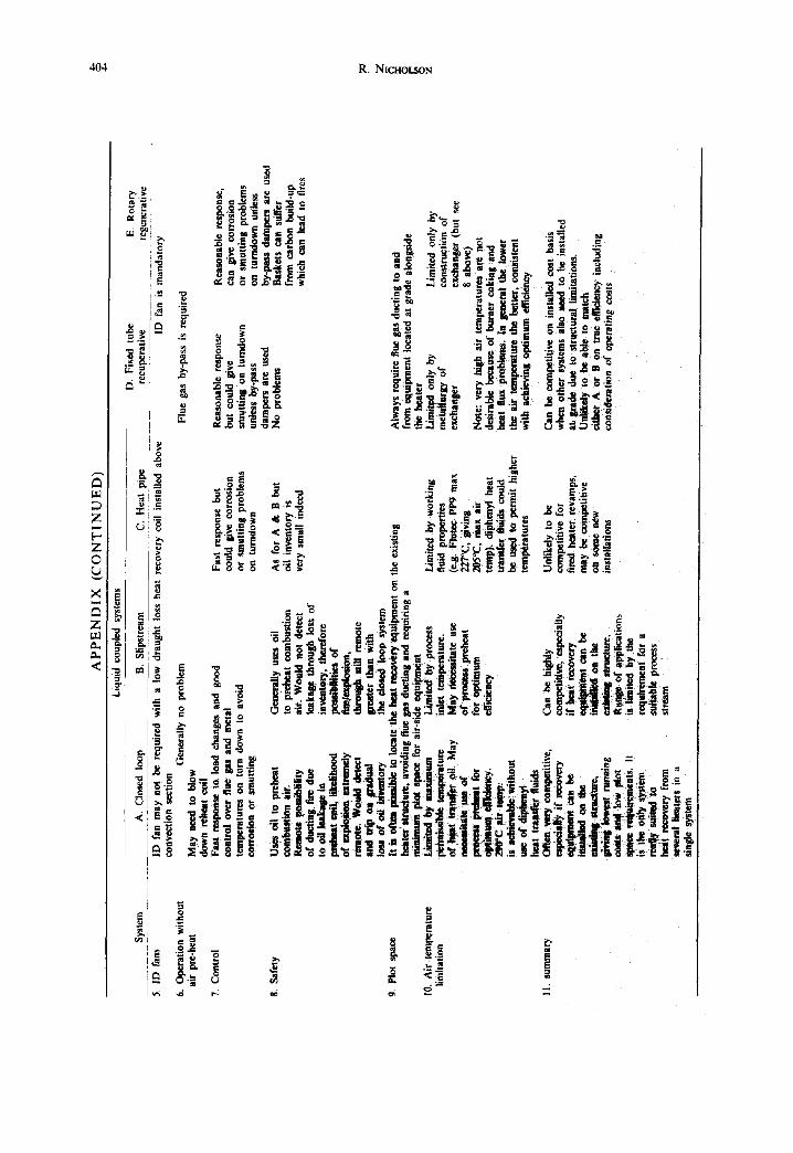
There are three commonly used types of air preheat system which may be classified as regenerative, recuperative or liquid-coupled. The Appendix gives, in tabular form, a comparison of air preheat systems for fired heaters.
2.1. Potential fuel savings
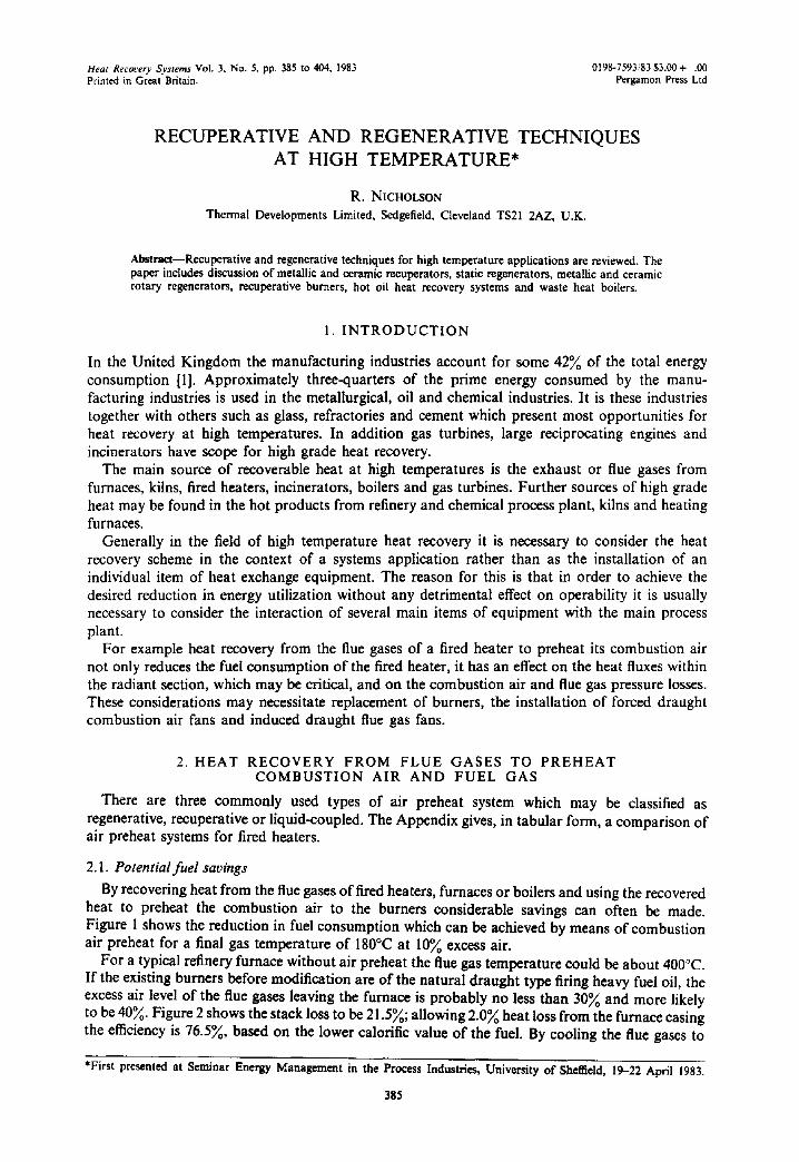
By recovering heat from the flue gases of fired heaters, furnaces or boilers and using the recovered heat to preheat the combustion air to the burners considerable savings can often be made. Figure 1 shows the reduction in fuel consumption which can be achieved by means of combustion air preheat for a final gas temperature of 180°C at 10~o excess air.
For a typical refinery furnace without air preheat the flue gas temperature could be about 400°C. If the existing burners before modification are of the natural draught type firing heavy fuel oil, the excess air level of the flue gases leaving the furnace is probably no less than 30~ and more likely to be 40~o. Figure 2 shows the stack loss to be 21.5~; allowing 2.0~ heat loss from the furnace casing the efficiency is 76.5~0, based on the lower calorific value of the fuel. By cooling the flue gases to
*First presented at Seminar Energy Management in the Process Industries, University of Sheffield, 19-22 April 1983.
385
386 R. NtcrtoLso,~
! ~ , t m , . c-c~/
; - _ _
# o - 180 I0 2O 30 40 50 60
Excess olr (%)
Fig. 1. Potential fuel savings by combustion air preheat
180°C with no change in excess air the flue gas loss is reduced to 9.0% and the efficiency becomes 89.0. If in addition, by the installation of forced draught burners, the excess air can be reduced to 10% the resulting efficiency becomes 90.9%. The preheated combustion air temperature will be around 260°C for 15°C ambient temperature, assuming that all of the heat recovery from the flue gases goes into preheating the combustion air.
If the furnace has an average absorbed duty of 100 GJ/h over an 8000 h annual operation and fuel costs £3.00/GJ, the potential savings are given below.
Annual Fuel Potential Value of
Efficiency Consumed Savings Savings % (net CV) (G J/h) (G J/h) (£)
Base Case 400°C flue gas 40% excess air
Air Preheat 180°C flue gas 40% excess air
Air Preheat 180°C flue gas 10% excess air
76.5 130.7
89.0 112.4 18.3 439000
90,9 110.0 20.7 497 000
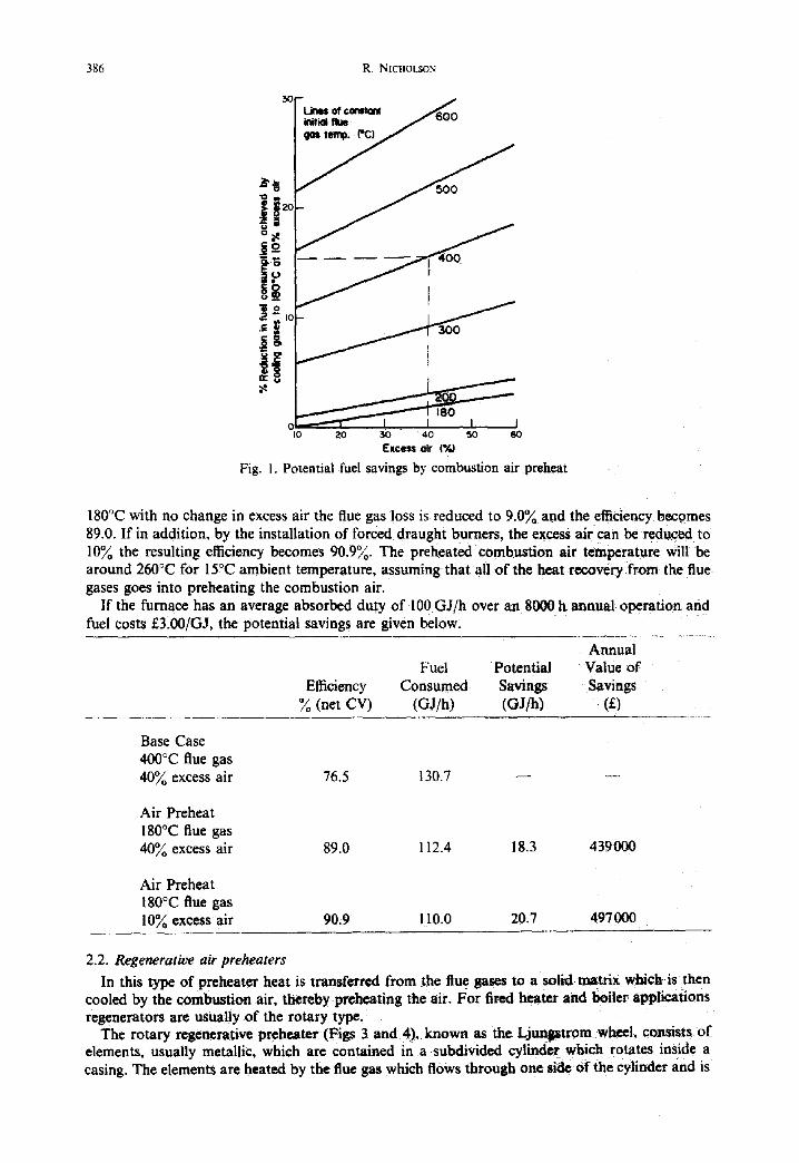
2.2. Regenerative air preheaters In this type of preheater heat is transferred from the flue gases to a solid matrix which i s then
cooled by the combustion air, thereby prchgating the :air. For fired heater and boiler app~ations regenerators are usually of the rotary type,
The rotary regenerative preheater (Figs 3 and 4), known as the Ljunptrom w ~ l , consists of elements, usually metallic, which are contained in a subdivided cylinder whichlrotates inside a casing. The elements are heated by the flue gas which flows through one side of the cylinder and is

Recuperative and regenerative techniques at high temperature 387
3o - Lines of constant % excess air
~lO -
- I -
I i
IY I II I I 0 I00 200 300 400 500
Temperature ('C)
I 6oo
Fig. 2. Heat content of combustion products.
Stack
¢-_~-~,~ Flue gas damper
"°r° I t II I sup°'' duct duct [ Radiantsection
/
Induced draft fan
duct air plenum
Fresh a i r - ~ ~ . . . . . . . . . . inlet Forced
draft fan Fig. 3. Rotary regenerative air preheater application to process heater.
388 R. N1CHOL.SON
3revJmin
Fig. 4. Rotary regenerative preheater.
HOt air
subsequently cooled by the combustion air on the other side as the wheel rotates. Baffles subdivide the cylinder; there arc also seals between the cylinder and casing to limit the amount of leakage from the air side to the flue gas side. This leakage lowers the gas exit temperature by 10-I 5°C which limits the level of efficiency attainable without cooling the flue gas below its acid dew point. Corrosion will normally occur at the cold end of the elements which will require periodic replacement. For boiler and fired process heater applications both forced and induced draught fans are required.
For metallurgical applications ceramic silicon nitride elements have been developed to permit much higher operating temperatures. BSC together with Babcock Woodall-Duckham is developing a ceramic rotary regenerator to provide a compact and efficient air preheater for use on reheating and other high output directly fired furnaces [2]. Energy recovery ratios of 85% arc possible with countcrcurrent air and gas flows, which will allow preheats of 1100°C from exchange with waste gases at 1300°C. Flexible seals are used to minimise leakage between the twosections of the regenerator. Application of the ceramic rotary regenerator to steel reheating furnaces could increase the air preheat temperature from say 400°C, typical of current practice, to 770°C, providing a 20% fuci saving. The higher air temperature would require changes to burners, air mains and blowers to permit application to existing furnaces, with associated costs, also there may be plot space limitations.
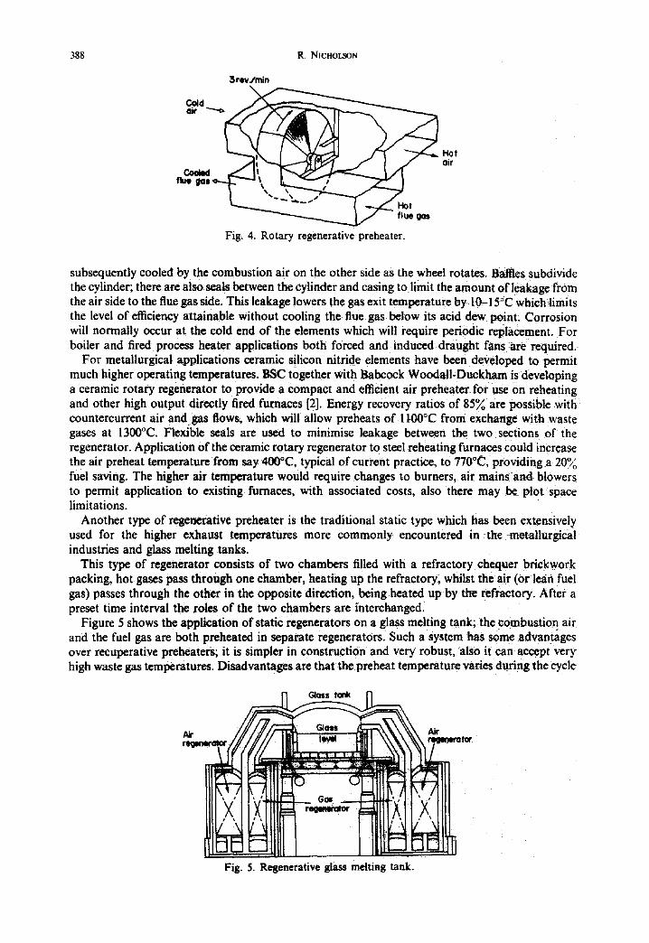
Another type of regenerative preheater is the traditional static type which has been extensively used for the higher exhaust temperatures more commonly encountered in the metallurgical industries and glass melting tanks.
This type of regenerator consists of two chambers filled with a refractory chequer brickwork packing, hot gases pass through one chamber, heating up the refractory, whilst the air (or lean fuel gas) passes through the other in the opposite direction, being heated up by the refractory. After a preset time interval the roles of the two chambers are interchanged.
Figure 5 shows the application of static regenerators on a glass melting tank; the combustion air and the fuel gas arc both preheated in separate regenerators. Such a system has some advantages over recuperative preheaters; it is simpler in construction and very robust, also it can accept very high waste gas temperatures. Disadvantages are that the preheat temperature varies during the cycle
l°-i I N
I
~ tc¢
Fig. 5. Regenerative glass melting tank.
Recuperative and regenerative techniques at high temperature 389
Flue
"..:':.:-.??)::
inlet i
Fig. 6. Pebble air heater.
i o
and the efficiency of heat recovery can be significantly reduced by uneven distribution of the waste gases in the regenerator and also by heat losses from the setting. Static regenerators must be designed to be able to handle all the waste gases and air used throughout a furnace campaign, which for a glass tank may last 3 yr, during which time the efficiency may be reduced substantially by blockage due to dust, slag or spalled bricks despite regular on-line steam lancing of the regenerator passages. The reduced efficiency results in greater fuel, air and waste gas flows. These considerations together with developments in the design of recuperators have meant that static regenerators have in many industries been superceded by metallic recuperators, which in turn may be eventually replaced or augmented by ceramic rotary regenerators, possibly using the latter to take the sting out of the gas stream before it enters the recuperator.
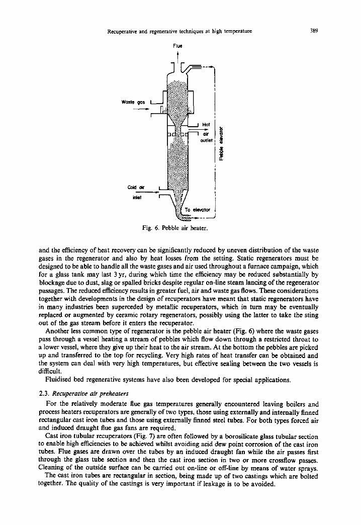
Another less common type of regenerator is the pebble air heater (Fig. 6) where the waste gases pass through a vessel heating a stream of pebbles which flow down through a restricted throat to a lower vessel, where they give up their heat to the air stream. At the bottom the pebbles are picked up and transferred to the top for recycling. Very high rates of heat transfer can be obtained and the system can deal with very high temperatures, but effective sealing between the two vessels is difficult.
Fluidised bed regenerative systems have also been developed for special applications.
2.3. Recuperative air preheaters
For the relatively moderate flue gas temperatures generally encountered leaving boilers and process heaters recuperators are generally of two types, those using externally and internally finned rectangular cast iron tubes and those using externally finned steel tubes. For both types forced air and induced draught flue gas fans are required.
Cast iron tubular recuperators (Fig. 7) are often followed by a borosilieate glass tubular section to enable high efficiencies to be achieved whilst avoiding acid dew point corrosion of the cast iron tubes. Flue gases are drawn over the tubes by an induced draught fan while the air passes first through the glass tube section and then the cast iron section in two or more crossflow passes. Cleaning of the outside surface can be carried out on-line or off-line by means of water sprays.
The cast iron tubes are rectangular in section, being made up of two castings which are bolted together. The quality of the castings is very important if leakage is to be avoided.

390 R. NICHOLSON
O Fin= inside end outside Hot flue gas
only / . ~
olr Gloss ~.., tubes Cooled flue gas
Fig. 7. C o m b i n e d cast i ron and glass tube recuperator .
Earlier glass tube sections were susceptible to leakage around the seals and breakages due to thermal expansion, but these problems have largely been overcome by the use of PTFE flexible seals. The inside surface of the tubesheets are also lined with PTFE to prevent corrosion.
The steel finned tube recuperator (Fig. 8) is most likely to find application where flue gases are relatively clean and low in sulphur content. Air flows through the tube banks in multiple crossflow passes which may be arranged to avoid dew point problems. Twisted tapcsmay be used to improve the in-tube heat transfer coefficient and sootblowers are used to maintain the finned surface in a clean condition.
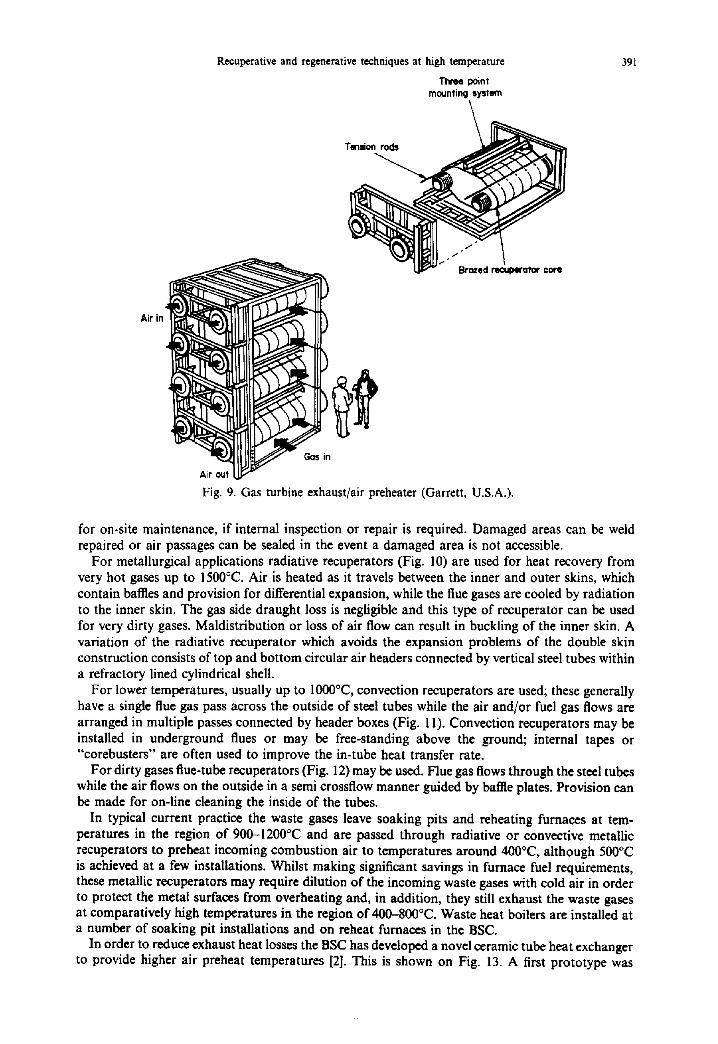
For heat recovery from gas turbine exhaust at around 500°C the modular brazed core rccuperator has been developed by Garrett Corporation in the USA (they call it a regenerator). This consists essentially of a modular plate exchanger, shown in Fig. 9, where the exhaust gas passes either horizontally or vertically through alternate passages between the plates while the air passess through the plate core from the inlet to outlet plenum in the remaining passages. All the flow paths have serpentine fins for improved heat transfer. Manways are provided to gain access into the air plenums
F ~ d
/
Cooled flue gas Fig. 8. Finned steel tube recuperator.
Air in
Recuperative and regenerative techniques at high temperature
Three poin) mounting system
T e n d o n ~
~ Brozed recuperator core
Fig. 9. Gas turbine exhaust/air preheater (Garrett, U.S.A.).
391
for on-site maintenance, if internal inspection or repair is required. Damaged areas can be weld repaired or air passages can be sealed in the event a damaged area is not accessible.
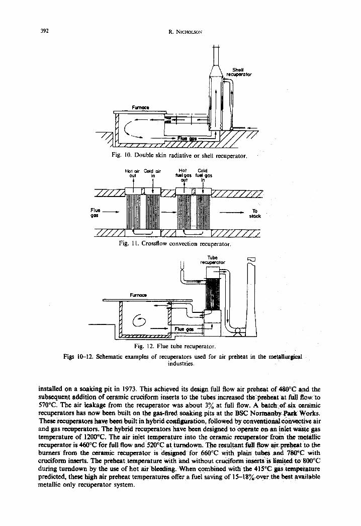
For metallurgical applications radiative recuperators (Fig. 10) are used for heat recovery from very hot gases up to 1500°C. Air is heated as it travels between the inner and outer skins, which contain baffles and provision for differential expansion, while the flue gases are cooled by radiation to the inner skin. The gas side draught loss is negligible and this type of recuperator can be used for very dirty gases. Maldistribution or loss of air flow can result in buckling of the inner skin. A variation of the radiative recuperator which avoids the expansion problems of the double skin construction consists of top and bottom circular air headers connected by vertical steel tubes within a refractory lined cylindrical shell.
For lower temperatures, usually up to 1000°C, convection recuperators are used; these generally have a single flue gas pass across the outside of steel tubes while the air and/or fuel gas flows are arranged in multiple passes connected by header boxes (Fig. 11). Convection recuperators may be installed in underground flues or may be free-standing above the ground; internal tapes or "corebusters" are often used to improve the in-tube heat transfer rate.
For dirty gases flue-tube recuperators (Fig. 12) may be used. Flue gas flows through the steel tubes while the air flows on the outside in a semi crossflow manner guided by baffle plates. Provision can be made for on-line cleaning the inside of the tubes.
In typical current practice the waste gases leave soaking pits and reheating furnaces at tem- peratures in the region of 900-1200°C and are passed through radiative or convective metallic recuperators to preheat incoming combustion air to temperatures around 400°C, although 500°C is achieved at a few installations. Whilst making significant savings in furnace fuel requirements, these metallic recuperators may require dilution of the incoming waste gases with cold air in order to protect the metal surfaces from overheating and, in addition, they still exhaust the waste gases at comparatively high temperatures in the region of 400-800°C. Waste heat boilers are installed at a number of soaking pit installations and on reheat furnaces in the BSC.
In order to reduce exhaust heat losses the BSC has developed a novel ceramic tube heat exchanger to provide higher air preheat temperatures [2]. This is shown on Fig. 13. A first prototype was
392 R. N[CHOLSON
Fig. 10. Double skin radiative or shell recuperator.
Hot oir Coid air Hot Cold out in fuelgas fuel (]as
out in
Fig. 11. Crossflow convection recuperator.
Tube ;~3 t l recupermor
Furnace
, , ~ ~ i , ~ ' I ~ ' - \ , I
Fig. 12. Flue tube recuperator,
Figs 10-12. Schematic examples of recuperators used for air preheat in the metallurgical industries.
installed on a soaking pit in 1973. This achieved its design full flow air preheat of 480°C and the subsequent addition of ceramic cruciform inserts to the tubes increased the preheat at full flow to 570°C. The air leakage from the recuperator was about 3~o at full flow. A batch of six ceramic recuperators has now been built on the gas-fired soaking pits at the BSC Normanby Park Works. These recuperators have been built in hybrid configuration, followed by conventional convective air and gas recuperators. The hybrid recuperators have been designed to operate on an inlet waste gas temperature of 1200°C. The air inlet temperature into the ceramic reeuperator from the metallic recuperator is 460°C for full flow and 520°C at turndown. The resultant full flow air preSeat to the burners from the ceramic recuperator is designed for 660°C with plain tubes and 780°C with cruciform inserts. The preheat temperature with and without cruciform inserts is limited to 800°C during turndown by the use of hot air bleeding. When combined with the 415°C gas temperature predicted, these high air preheat temperatures offer a fuel saving of 15-18% over the best available metallic only recuperator system.

Recuperative and regenerative techniques at high temperature 393
Flexible seal
._ 'IIII Nil.,/ , II t ,II
T Waste gas
Fig. 13. Ceramic tube recupcrator.
Glazed ceramic tube
Heat transfer coefficients are quite low and therefore the exchanger's performance is not greatly affected by fouling, but for the same reason the ceramic tube recuperator is not suitable for applications where the volume of waste gases is large because of the physical size of the exchanger required, hence the current interest in the compact ceramic rotary regenerator described earlier. Applications have been mainly on soaking pits and on a muffle kiln in the pottery industry, but suitable tube materials have been identified for application to reverberatory furnaces in the aluminium and copper industries and in the glass industry.
2.4. Recuperative burners
Recuperative burners ([3],[4],[5]) provide a means of greatly increasing the efficiency of small furnaces. Self recuperative burners consist of a tunnel type burner surrounded by a counterflow concentric heat exchanger. Flue gases are extracted from the furnace, through the recuperator, by an air driven eductor supplied with air from a common fan which also provides the combustion air for the burner. Normally all the combustion products are extracted through the recuperator. By controlling the amount of eductor air the furnace pressure can be maintained at the desired level. Because of the changes in combustion air density on warm up and high/low firing, constant ratio control equipment is necessary to maintain the optimum fuel-air ratio over the range of operating conditions.
The term 'self recuperative' has been adopted to distinguish burners having integral recuperators from those where the recuperator is separated from the burner itself. Self recuperative burners are designed for gas firing at heat liberations of up to 600 kW (gross). For a furnace exit temperature of 1400°C a 600°C air preheat temperature can result in around 40% reduction in fuel consumption.
Application of recuperative burners is widespread in continuous reheating furnaces, batch forge furnaces and heat treatment of furnaces in the metals industries, on kilns in the refractories and potteries industries and in a wide range of heating operations when incorporated into radiant tube heaters.
Self recuperative burners have gained acceptance for a variety of direct fired furnace and kiln applications. The main limitation of self recuperative burners in direct fired furnaces is that particulates in the furnace atmosphere can induce fouling which affects efficiency and also burner life. They have the advantages that a separate heat exchanger is not required and the preheated air is available directly at the point of combustion.
For some direct fired applications where temperature uniformity of the furnace stock is very critical the extraction of a hot atmosphere at the burner could upset the temperature distribution within the furnace. It is for such applications that separated recuperators will find application with each burner having its own recuperator or perhaps one recuperator to a pair of burners. Such recuperators may be metallic of a similar type to those employed on the self recuperative burner but a recently introduced alternative is in the form of a compact ceramic cube in a refractory lined

394 R. NICHOLSON
Gas
Comb~ti=~ Ixoduct=
Furnoce
Spark plug
Air
Metallic recimulation
tube
M e ~ ~ t radiant tube /
C4rami¢ re¢irau~tian tu~e
Ceramic radianl tube
Fig. 14. Self recuperative burners applied to metallic and ceramic radiant tubes.
Refractory ~ug
housing. The cube comprises a ceramic matrix composed of alternate layers of ceramic passages positioned at right angles to each other separated by a thin (0.05") wall. This ceramic recuperator is manufactured by GTE in United States and supplied in the U.K. through Hotwork Development Limited.
Hot exhaust gases are directed through the unit in one direction, heating the ceramic matrix, thus removing much of the heat energy from the hot exhaust stream. Incoming combustion air is heated as it passes through the ceramic matrix in the other direction thus removing the stored heat. This design makes possible a highly effective heat exchanger that can handle high temperature furnace exhausts up to 1370°C. The high heat transfer surface area and compact ceramic construction make the cube attractive for both low and high temperature applications.
A logical development of self recuperative burners is for the firing of radiant tubes {6] which are widely used in a variety of applications where it is essential that combustion products or flames do not come into contact with the work (Fig. 14). The biggest application is in metallurgical heat treatment where controlled atmospheres are required or where treatment is carried out in a vacuum such as vacuum annealing, but other applications include food processing, foundries and the textile industry.
For tube temperatures up to 1050°C metallic radiant tubes are used; tube efficiencies are in the range 60-70% (gross). The radiant tube is of single ended construction, supported by a flange near the burner and a spigot at the dosed clad. A recuperative burner fits into the tube through the furnace wall. This burner is a nozzle mixing type with a high exit velocity. A recirculation tube is fitted near to the burner tunnel. This ensures uniform temperatures along the tube and a high rate of convective heat transfer from the combustion products to the tube walls. The outgoing combustion products are cooled by the incoming air as they pass through the recuperator.
Metallic radiant tubes are suitable for proee~ temperatures up to about 970"~C, for higher temperatures up to 1250°C ceramic radiant tubes are used. Tube temperatures can be as high as 1350°C with tube effieiencies around 50%.
The radiant tube consists of a plain ceramic tube held between refractory lined metallic tubular extensions. An axial compr~ive force is applied, via a spring loaded plate, to reduce tensile stresses in the ceramic material and to ensure-an effective refractory to ceramic seal. A recuperative burner is used to provide high e~eiency operation and an inner ceramic tube recirculates the combustion products to provide a uniform temperature distribution.

Recuperative and regenerative techniques at high temperature
7:3.92*/. Net efficiency 8 8 . 4 3 % Net efficiency before revamp of fer revamp
395
Pr
fer oii
P I
aft fan Air pre~eat tol l
Natural draf t Forced draft no Induced draft
Fig. 15. Closed loop air preheat system without induced draught fan.
A somewhat similar application of self recuperative burners developed by British Gas [7] is in ceramic tube immersion heaters used for the melting of aluminium or zinc. They provide a compact and much more efficient alternative to reverberatory hood heating and can be used to replace cast iron pots where pot life is a problem. Immersion tubes are made of silicon carbide, chosen because of high thermal conductivity, good thermal stock resistance and hot strength. It is resistant to hot gas corrosion and can withstand cyclic oxidising and reducing conditions which may occur at different points within the combustion chamber. Gases leave the recuperator at temperatures between 550 and 750°C to give heater thermal efficiencies of 60-70~o depending on the tube size and process temperature.
2.5. Liquid-coupled air preheat systems There are two principal types of liquid-coupled preheat systems; these being the closed loop
system and the slipstream system. These are mainly applicable to fired process heaters. In the closed loop system the working fluid, very high pressure water or more frequently heat transfer oil (patented by Fallon Engineering Co)([8], [9]), circulates through an extended surface coil in the flue gas stream, where the fluid is heated, and then through a coil in the combustion air where the fluid is cooled to preheat the air.
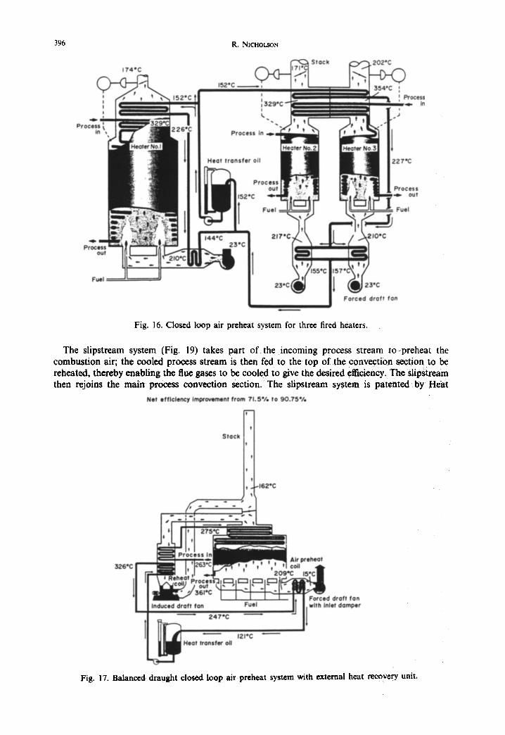
The main plant items consist of the reheat and preheat coils, the latter may be skid-mounted along with the expansion/blowdown receiver, circulating pumps, control panels and other ancillary equipment. The skid is usually located close to the fired heater and air ducting is very short. Forced draught and induced draught fans are optional; sometimes the reheat coil can be placed above the process convection section with a draught loss sufficiently small that an induced draught fan is not required (Fig. 15). It is possible to combine a number of fired heaters in the same heat recovery system (Fig. 16). Many existing heaters cannot carry the load of a reheat coil and induced draught fan; Fig. 17 shows a balanced draught system (FD and ID fans) with an adjacent structure containing the reheat coil and ID fan; this equipment can be prefabricated and erected before a plant shut-down thus minimising the heater downtime. Figure 18 illustrates another arrangement whereby each burner or small groups of burners have their individual FD fan, preheat coil, duct and plenum; this arrangement minimises plot space.
396 R. NiCHOLSON
i
4 . - '
In
174eC
i
i k
Process In ..D
Stack 202,C
In
Heot t ranster 011
P r o c e s s out!
Fuel
Process , .~ out
: Fuel
~.mm process
out 23"C
Fud
L I Forced draft fon |
Fig. 16. Closed loop air preheat system for three fired heaters.
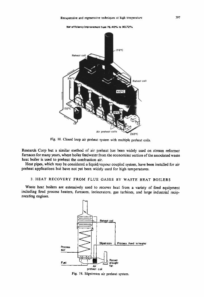
The slipstream system (Fig. 19) takes part of the incoming process stream to preheat the combustion air; the cooled process stream is then fed to the top of the convection section to be reheated, thereby enabling the flue gases to be cooled to give the desired efficiency. The slipstream then rejoins the main process convection section. The slipstream system is patented by Heat:
Net efficiency improvement from 71.S'/e to 90 .75%
,-"1
,I Stock
!
,I t
tt t J(,-162"C
Fig. 17. Balanced draught closed loop air preheat system with external heat recovery unit.
Recuperative and regenerative techniques at high temperature
Net efficiency improvement from 76.40"/, to 90.72*/,
397
coil
Z63"G Fig. 18. Closed loop air preheat system with multiple preheat coils.
Research Corp but a similar method of air preheat has been widely used on stream reformer furnaces for many years, where boiler feedwater from the economiser section of the associated waste heat boiler is used to preheat the combustion air.
Heat pipes, which may be considered a liquid/vapour coupled system, have been installed for air preheat applications but have not yet been widely used for high temperatures.
3. HEAT RECOVERY FROM FLUE GASES BY WASTE HEAT BOILERS
Waste heat boilers are extensively used to recover heat from a variety of fired equipment including fired process heaters, furnaces, incinerators, gas turbines, and large industrial recip- rocating engines.
2 Reheat coil ,
i
I
F~ocess exit
Fuel
.J Slipstream
~ Forced drought
Air fan preheat coil
Fig. 19. Slipstream air preheat system.
Process feed to heater
398 R. NICHOLSON
~soo 4 0 0
\ *,,.'_'--- ~oo/Sht'r Generator Econ'r
I Heat e l ~ o ~ l
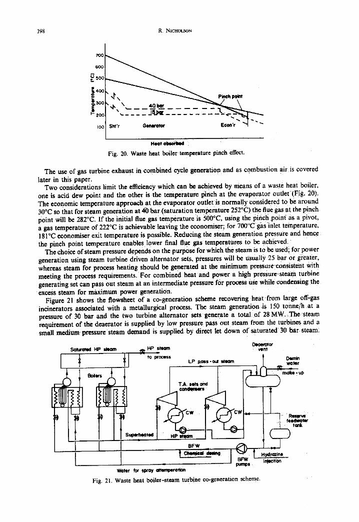
Fig. 20. Waste heat boiler temperature pinch effect.
The use of gas turbine exhaust in combined cycle generation and as combustion air is covered
later in this paper. Two considerations limit the efficiency which can be achieved by means of a waste heat boiler,
one is acid dew point and the other is the temperature pinch at the evaporator outlet {Fig. 20). The economic temperature approach at the evaporator outlet is normally considered to be around 30°C so that for steam generation at 40 bar (saturation temperature 252°C) the flue gas at the pinch point will be 282°C. If the initial flue gas temperature is 500°C, using the pinch point as a pivot, a gas temperature of 222°C is achievable leaving the economiser; for 700°C gas inlet temperature, 181 °C economiser exit temperature is possible. Reducing the steam generation pressure and hence the pinch point temperature enables lower final flue gas temperatures to be achieved.
The choice of steam pressure depends on the purpose for which the steam is robe used; for power generation using steam turbine driven alternator sets, pressures will be usually 25 bar or greater, whereas steam for process heating should be generated at the minimum pressure consistent with meeting the process requirements. For combined heat and power a high pressure steam turbine generating set can pass out steam at an intermediate pressure for process use while condensing the excess steam for maximum power generation.
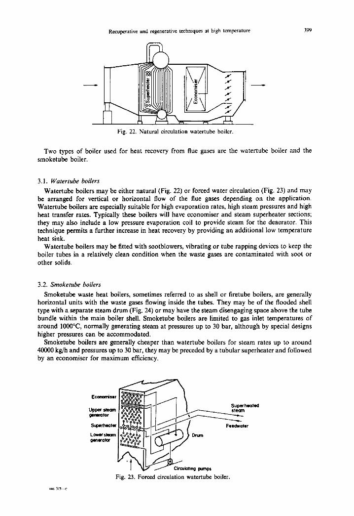
Figure 21 shows the flowsheet of a co-generation scheme recovering heat from large off-gas incinerators associated with a metallurgical process. The steam generation is 150 tonne/h at a pressure of 30 bar and the two turbine alternator sets generate a total o f 28 MW. The steam requirement of the deaerator is supplied by low pressure pass out steam from the turbines and a small medium pressure steam demand is supplied by direct let down of saturated 30 bar steam.
Soluroted HP slmom ~ l ~ l m ~- to process
Boilers
I I t .
vent
LP ~Oss-oul steam ~ p
HP Iteem l 1
Water for spray ~ra t ion Fig. 21. Waste heat boiler.steam turbine co-generation scheme.
Recuperative and regenerative techniques at high temperature
x L/-
f rn
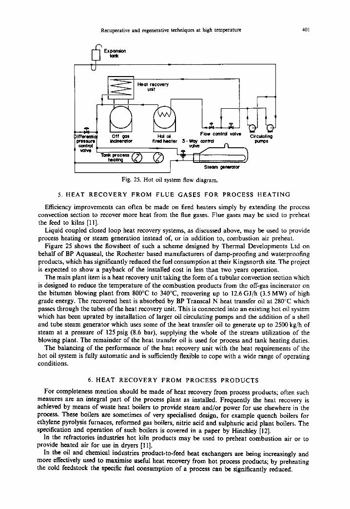
Fig. 22. Natural circulation watertube boiler.
399
Two types of boiler used for heat recovery from flue gases are the watertube boiler and the smoketube boiler.
3.1. Watertube boilers
Watertube boilers may be either natural (Fig. 22) or forced water circulation (Fig. 23) and may be arranged for vertical or horizontal flow of the flue gases depending on the application. Watertube boilers are especially suitable for high evaporation rates, high steam pressures and high heat transfer rates. Typically these boilers will have economiser and steam superheater sections; they may also include a low pressure evaporation coil to provide steam for the deaerator. This technique permits a further increase in heat recovery by providing an additional low temperature heat sink.
Watertube boilers may be fitted with sootblowers, vibrating or tube rapping devices to keep the boiler tubes in a relatively clean condition when the waste gases are contaminated with soot or other solids.
3.2. Smoketube boilers
Smoketube waste heat boilers, sometimes referred to as shell or firetube boilers, are generally horizontal units with the waste gases flowing inside the tubes. They may be of the flooded shell type with a separate steam drum (Fig. 24) or may have the steam disengaging space above the tube bundle within the main boiler shell. Smoketube boilers are limited to gas inlet temperatures of around 1000°C, normally generating steam at pressures up to 30 bar, although by special designs higher pressures can be accommodated.
Smoketube boilers are generally cheaper than watertube boilers for steam rates up to around 40000 kg/h and pressures up to 30 bar, they may be preceded by a tubular superheater and followed by an economiser for maximum efficiency.
x~s 3/5--c
E¢Ol',lOl~$or
Upper steam generator
Superheatm
Lower steam general'
Superheated
Fig. 23. Forced circulation watertube boiler.

400 R. NICHOLSON
Fig. 24. Flooded shell smoketube boiler.
4. UTILIZATION OF GAS TURBINE EXHAUST
Gas turbines produce exhaust gases at around 500°C containing about 16% by weight of oxygen: this oxygen can be used to support the combustion of additional fuel. Besides exhaust gas recuperators discussed earlier, another means of using gas turbine exhaust is for combined cycle power generation where the gas turbine shaft power is used to generate electricity and the exhaust gases are used to produce steam to drive a steam turbine generating set, thereby greatly improving the cycle efficiency [10].
If the oxygen in the exhaust gas is fully utilized the gas turbine in effect acts as a forced draught 00 ° fan for the steam boiler and because of the very high temperatures attainable (18 C) the fuel
is burnt in a water cooled, radiant furnace and the boiler is virtually identical to the conventional fired type. The heat content of the gas turbine exhaust is increased approximately five fold and the steam turbine output can be 3--4 times that of the gas turbine. The combustion efficiency of the fuel is high, the "air" is highly preheated; consequently the overall efficiency is much higher than that of conventional steam plant. Several units of this design have been built but in recent years the trend has moved more towards the "supplementary" and "unfired" cycles.
The unfired cycle, as the name implies, consists simply of heat recovery from gas turbine exhaust by means of a waste heat boiler to produce steam for the steam turbine generating set. The waste heat boiler efficiency is limited by pinch point considerations as discussed earlier. By firing a relatively small amount of fuel to supplement the gas turbine exhaust the effective gas temperature entering the waste heat boiler is increased, enabling a lower final flue gas temperature to he achieved for a given steam generation pressure. Conversely steam pressures can be higher for this supplementary lired cycle than for the unfired cycle for a given back end t ~ a t u r e . The gas/steam turbine power ratio is around i. 1 : I for the supplementary fired cycle compared with about 2.5: I for the unfired cycle.
Overall efficieneies of around 43-44% can be achieved by single pressure combined cycles; a further 1-2 percentage points can be gained by the use of dual or triple pressure cyclesand by using the boiler feedwater for condensate heating. The selection of the best cycle for a particular application depends on many other factors including annual operating hours, gas turbine and boiler fuel costs, the degree of flexibility required, capital and operating costs.
Gas turbine exhaust has been used as combustion air for fired process heaters on a number of oil refineries, which often generate a large proportion of their electricity demand. Typically the combined efficiency of refinery boilers and steam turbine generating sets will be 22% (net) and the efficiency of fired process heaters 82°//0 (net). By selecting one or more fired heaters whose combustion air requirements closely match the gas turbine exhaust quantity it is possible to use a gas turbine to generate electricity and its exhaust as preheated combustion air to give an overall efficiency of about 82% (net). For example the exhaust from a gas turbine with 10 MW output will match proc~s beaters with an absorbed duty of 120MW (432 GJ/h). The resulting efficiency of 82% compares favourably with a combined efficiency of a 10 MW steam turbine generating set and the unmodified process heaters of only 67.8%.
Recuperative and regenerative techniques at high temperature 401
[~ Expansion tonk
_._¢__
Heat recovery unit
Off gas Hot oil Flow control volve Circulating incinerator fired heater 3 - Way conlrd pumps
va~ N I t
process - "~ I J ) ) Tank
I ~ ' ' Steam genemto¢ I
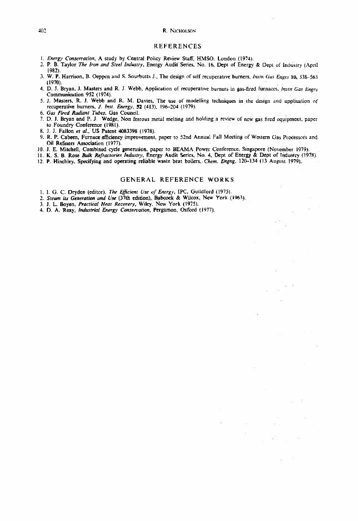
Fig. 25. Hot oil system flow diagram.
)iffefentic pressure control valve
5. H E A T R E C O V E R Y F R O M F L U E G A S E S F O R P R O C E S S H E A T I N G
Efficiency improvements can often be made on fired heaters simply by extending the process convection section to recover more heat from the flue gases. Flue gases may be used to preheat the feed to kilns [11].
Liquid coupled closed loop heat recovery systems, as discussed above, may be used to provide process heating or steam generation instead of, or in addition to, combustion air preheat.
Figure 25 shows the flowsheet of such a scheme designed by Thermal Developments Ltd on behalf of BP Aquaseal, the Rochester based manufacturers of damp-proofing and waterproofing products, which has significantly reduced the fuel consumption at their Kingsnorth site. The project is expected to show a payback of the installed cost in less than two years operation.
The main plant item is a heat recovery unit taking the form of a tubular convection section which is designed to reduce the temperature of the combustion products from the off-gas incinerator on the bitumen blowing plant from 800°C to 340°C, recovering up to 12.6 GJ/h (3.5 MW) of high grade energy. The recovered heat is absorbed by BP Transcal N heat transfer oil at 280°C which passes through the tubes of the heat recovery unit. This is connected into an existing hot oil system which has been uprated by installation of larger oil circulating pumps and the addition of a shell and tube steam generator which uses some of the heat transfer oil to generate up to 2500 kg/h of steam at a pressure of 125 psig (8.6 bar), supplying the whole of the stream utilization of the blowing plant. The remainder of the heat transfer oil is used for process and tank heating duties.
The balancing of the performance of the heat recovery unit with the heat requirements of the hot oil system is fully automatic and is sufficiently flexible to cope with a wide range of operating conditions.
6. HEAT RECOVERY FROM PROCESS PRODUCTS
For completeness mention should be made of heat recovery from process products; often such measures are an integral part of the process plant as installed. Frequently the heat recovery is achieved by means of waste heat boilers to provide steam and/or power for use elsewhere in the process. These boilers are sometimes of very specialised design, for example quench boilers for ethylene pyrolysis furnaces, reformed gas boilers, nitric acid and sulphuric acid plant boilers. The specification and operation of such boilers is covered in a paper by Hinchley [12].
In the refractories industries hot kiln products may be used to preheat combustion air or to provide heated air for use in dryers [1 I].
In the oil and chemical industries product-to-feed heat exchangers are being increasingly and more effectively used to maximise useful heat recovery from hot process products; by preheating the cold feedstock the specific fuel consumption of a process can be significantly reduced.
402 R. NICHOLSON
R E F E R E N C E S
1. Energy Conservation, A study by Central Policy Review Staff, HMSO, London (19741. 2. P. B. Taylor The Iron and Steel Industry, Energy Audit Series. No. 16. Dept of Energy & Dept of Industry (April
19821. 3. W. P. Harrison, B. Oeppen and S. Sourbutts J.. The design of self recuperative burners, lnstn Gas Engrs !0, 538-563
(19701. 4. D. J. Bryan, J. Masters and R. J. Webb, Application of recuperative burners in gas-fired furnaces, lnstn Gas Engrs
Communication 952 (1974). 5. J. Masters, R. J. Webb and R. M. Davies, The use of modelling techniques in the design and application of
recuperative burners, J. Inst. Energy, 52 (4131, 196-204 (1979). 6. Gas Fired Radiant Tubes, Gas Council. 7. D. J. Bryan and P. J. Wedge, Non ferrous metal melting and holding a review of new gas fired equipment, paper
to Foundry Conference (1981). 8. J. J. Fallon et al., US Patent 4083398 (19781. 9. R. P. Cabeen, Furnace efficiency improvement, paper to 52nd Annual Fall Meeting of Western Gas Processors and
Oil Refiners Association (19771. 10. J. E. Mitchell, Combined cycle generation, paper to BEAMA Power Conference. Singapore (November 19791. 11. K. S. B. Rose Bulk Refractories Industry, Energy Audit Series. No. 4. Dept of Energy & Dept of Industry ( 19781. 12. P. Hinehley, Specifying and operating reliable waste heat boilers, Chem. Engng, 120-134 (13 August 19791.
G E N E R A L R E F E R E N C E W O R K S
1. I. G. C. Dryden (editor), The E~fcient Use of Energy, IPC, Guildford (19751. 2. Steam its Generation and Use (37th edition), Babcock & Wilcox. New York (1963). 3. J. L. Boyen, Practical Heat Recovery, Wiley, New York (1975). 4. D. A. Reay, Industrial Energy Conservation, Pergamon. Oxford (19771.

Recuperative and regenerative techniques at high temperature 403
UJ
<
©
F- r.#3
0'3
[ . . < [.z..1 =: LU =¢
=¢
6
Z
I:.,
<
i
o ~,i p .=
- ~ i
.~=
._=
=._= ,.~ :~ =
~ = ~
, , = o = ~ "= 8 0 . -
, . -~= = = , • ~ ~ - o ~ , . ~ - ~ . - -~=~ .~ _ £ - = ~ ~, , . . - ~ .=
. ~ ~ , G ' . -
=6 & =
ea
- " = ~ E ~3 ~ ' =
o i *- = =+- .c : . .~ .~ .~
=.=:
. . .= ,.
#j Q. 0 C:
,-, =. o - m = = o < : ~ Z = : 'E. ~ .~ '~ = ~ = ~ ~= '~ .= .= . = ~ ~ ==" "~,E ~ "--,= '== T = . , ~ = ~= ".aS. 0===-= "=~= ""~ I
O ' ~ ~ J ; : v=
== , , . 5 . _ o o ~ 0 . £ = ~ . ° - = 0 =- d:::
= ~ . - = = 0 . = ~ ~ o .'- "- ,~'= =, ~'~-" ~.." o I
~ , = ~..= ~" < .~
• 0
g,
,~_ .¢= ~ ~, : ~) ~ . ~ . ~. E u - -
!q
I I .~_=
~ -~ .E ~ .o E = - E I t - - .=
404 R. N~CHOL~ON
Z
Z 0
B Z
<
I :,.+~
, - . ! ~ <::+
J~ i .m-
{= , _
.,3=p.-.£ +,+"
N =
I g
N
m" ~.+.~ =.= I:= l= .I~ [ ; ~ i . " I : .,=
t . = l ~J,,~=
+ + m + + ++'~ +;++ ~++
++ + + + +
~ = =-+- = -6
o ~ im m
++
~ ~ ~ ~ ^ ~ , , , ~ .~
@ m I : I= pa oS + C: am ~ ~_
• - ~ ~ ~ ~. " ~ ~ I:: l i + .
~.~ -~ 0 . ~
++;+~ +
++ i+]++ ++ +
- ._= + j ~ : . =
m m
..o ;~ m + + .-~ ..~.':~ ,,, + _ . ~ 5Vt' . ~ , = + .
l+[ + ' ~ " + ~ + + + ; + + + - i t + + u ~
..~ © "~
++.=~ ~ +~ .
. . . . . . 0 , + + , t , - ,+++ + J ++t+:++ ++ + + +, + + + ++ +;+ +++++,+ o + + , . + 1! += ,+ ++ ~+ +,,,+ ! | l : t , ~++ +, !0
+=-~ ~R ~ +i"~ "~ ~ ̀ '++
E
- + ,-,, ++ --. o p, ~ ~ =" . = ,,.+; <; ,-: ~ ~ =_ -