heat transfer in a through-ventilated induction motor
TRANSCRIPT
Heat transfer in a through-ventilated induction motor
S. J . Pic ke ri ng D. Lampard N. Hay T.F. Roylance
Indexing terms: Heat transfer, Induction motors
Abstract: The effects of varying the cooling air flow and its distribution on the heat transfer in a high-voltage, strip-wound, four-pole induction motor are reported. The flow variations were achieved by altering the motor speed, by removing the wafters, by increasing the flow resistance of the motor air inlets, or by the insertion of heat transfer augmentation devices in the stator-frame ducts. Heat transfer coefficients were deduced from the measurement of input power, and from miniature heat flux gauges attached to the surfaces. The overall heat transfer coefficient on the end-winding at the air outlet end (the fan end) was roughly double that at the air inlet end, the converse of the situation for lap and concentric wound motors. Large spatial variations in the end-winding local heat transfer coefficients occurred. This is attributed to the open nature of the winding which results in the individual loops behaving as separate bodies, each with a flow pattern dependent upon the angle of the approaching flow. There was a large increase in the overall heat transfer coefficient on the winding at the fan end when the wafters were removed. The use of transverse ribs in the stator- frame ducts was found to enhance heat transfer.
The primary differences between the low- and high- voltage configurations lie in the openness and topogra- phy of the stator windings, and in the presence of the protruding rotor bar ends which form a crude addi- tional fan in the high-voltage motor. Lap win yields an almost continuous surface which is somewhat irregular and rough. Concentric winding results in the wire bundles retaining their identities, giving more openness at the stator face, and a deeply fluted, irregu- lar surface. High-voltage windings have strips com- pletely separated from each other and wrapped with insulation, resulting in a very open structure over the full length of the end-winding. Changes in winding openness and surface irregularity are expected to result in different air flows and flow distributions, giving var- iations in the magnitude, and possibly the behaviour, of the heat transfer coefficients. Marked differences in flow distribution were observed between the lap and concentric wound motors [2], but although the heat transfer coefficients were higher for the concentric wound motor, the general behaviour was similar. In particular, the end-winding overall heat transfer coeffi- cient at the inlet end was roughly double that at the fan end for both cases.
This paper presents the heat transfer from the simu- lated high-voltage end-winding and stator core pack surfaces and explores their linkage to the cooling air flows.
Introduction
This paper reports work on heat transfer in electric motors. The objective was to acquire data relevant to the thermal design of induction motors, and to gain an insight into the mechanisms controlling the convective heat transfer occurring on their blown surfaces. Thus, both heat and air flow data were required. Tests on a low-voltage motor fitted successively with a lap wound stator and a concentric wound stator have already been reported [I , 21. This paper deals primarily with similar tests on a high-voltage wound stator fitted within the same machine frame.
0 IEE, 1998 IEE Proceedings online no 19982169 Paper first received 23rd March and in revised form 16th July 1998 The authors are wth the Department of Mechanical Engheenng, Univer- sity of Nottingham, Notangham, NG7 2RD, UK
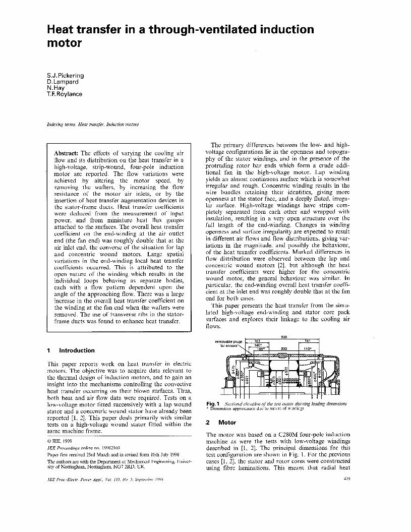
Fig. 1 Sectional elevation of the test motor showing leading dimensions * Dimensions approximate due to nature of windings
2 Motor
The motor was based on a C280M four-pole induction machine as were the tests with low-voltage windings described in [I , 21. The principal dimensions for this test configuration are shown in Fig. 1. For the previous cases [ I , 21, the stator and rotor cores were constructed using fibre laminations. This meant that radial heat
429 IEE Psoc.-Elects. Power Appl , Vol 145, No 5, September 1998

conduction was negligible. For the investigation reported here, the stator was built from steel lamina- tions, and was provided with a specially produced sim- ulated high-voltage winding. A 41tW motor was used to drive the test motor via a V-belt and pulley system con- nected to the fan end shaft extension. A smoothed, sta- bilised voltage DC power supply was used to provide about 2.7kW of resistive heating from the coil without the generation of iron losses in the core laminations.
3 processing
3. I Temperature and heat transfer measurements 77 thermocouples were embedded in the winding, or fixed on its surface, or on the end-winding surfaces. A further 14 were distributed on the end faces and outer cylindrical surface of the stator core. The end-winding thermocouples were divided among three well-spaced coils at circumferential locations chosen to complement the built-in thermocouples of the end-winding heat flux gauges which were sited mostly on a single coil, see Fig. 2.
Instrumentation, data acquisition and data
rotation rotation (anti-clockwise seen (clockwise seen
from non-fan end) a b
from non-fan end)
Fig. 2 n Inlet end b Fan (outlet) end
Location of heat flux gauges on end-windings
ntrally placed ermocouples
Fig. 3 surfaces
Positions of heat f lux gauges on staior core and stator-jrame duct
The adjacent coil was instrumented only at entry to the slot. The positions of the heat flux gauges on the stator core and stator-frame air duct surfaces are shown in Fig. 3.
For each end-winding, the overall heat transfer coef- ficient a,, was calculated from the heat flux q from the end-winding using:
where A,, is the envelope area of the end-winding, consistent with [l, 21, T,, is the end region air tempera- ture measurement, and T,, is the average end-winding surface temperature. A revised method to estimate q
430
was required. In [l, 21, the heat flow from the windings embedded in the slots to the end-windings was esti- mated from the axial temperature gradients given by thermocouples embedded in the coils near the slot exits. For the high-voltage winding, no consistent trend could be obtained from the thermocouples in this region, probably because an insulating material was not used for the core laminations in this case.
However, a worst case estimate indicated that the axial heat flow between the end-winding at the fan end and the stator core never exceeded 10% of the dissipa- tion within the end-winding. It was therefore decided that in the calculation of q, it was appropriate to assume this heat flux to be zero. Thus, q for the fan end winding was calculated from the length of copper in the end-winding, the total length of copper in the winding, and the measured power input to the winding.
To obtain the end-winding heat flux for the inlet end, area-weighted heat fluxes for the two end-windings were deduced from the local values measured by the heat flux gauges. Their ratio was then applied to the value estimated for the fan end as detailed above.
For the low-voltage cases, the estimated uncertainty in a,, was 25%. This is largely systematic in origin, see [l], and a -.lo% change with parameter variation was therefore believed to be significant. The modified calcu- lation approach needed here will lead to an increased uncertainty, but this should not exceed +30%.
3.2 Air flow measurements The equipment and procedures used have been described in [l, 21. In brief, these were calibrated air inlet ducts for total air flows, pitot tube traverses for stator-frame duct flows, and a five-hole probe for inter- nal flow field measurements.
4 Test programme and parameters
The programme and parameters closely followed those given in [l, 21. A set of 'base case' data was first estab- lished with the motor in a standard configuration, with 25" long wafters, running at 1500 redmin. Then, the speed was varied, and flow restrictors were introduced. Wafter lengths were not varied, however, as the effect of the flow from the bar ends was expected to be dom- inant. To check this, tests were done with and without wafters of standard (25") length. A further depar- ture from previous practice was in the measurement of the heat transfer coefficients on the stator-frame and air gap surfaces, and the use of heat transfer enhancing devices in the stator ducts.
5 Results
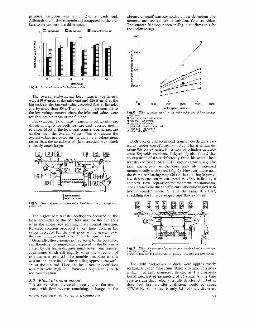
5. I Base case As in previous tests, the asymmetry of the air inlets led to a 2% imbalance of flow between them. The non-uni- form distribution of flow amongst the stator-frame ducts seen for the low-voltage windings was again present and was similar in form to that for the concen- tric wound motor. The mean velocities obtained from traverses over the cross-sections of the five accessible ducts are shown in Fig. 4.
Substantial surface temperature variations occurred. At the inlet end, with an air inlet temperature of 25.3"C, the winding surface temperature varied from 28.9"C to 36.2"C. At the fan end, the corresponding range was 32.4"C to 42.1"C. The circumferential tem-
IEE Proc.-Electr Power Appl , Vol. 145, No 5, September 1998
perature variation was about 2°C at each end. Although small, this is significant compared to the sur- face-to-air temperature differences.
~ ~ 6 0 0 E 5 -- 0 ._ 0,
E 8400
z E B
L
c c
$200
0 lap wound HV wound concentric wound
-
-
- b
n
C d e f AV.
stator duct Fig. 4 Mean velocities in back-ojdator ducts
The overall end-winding heat transfer coefficients were 210W/m2K at the inlet end and 326W/m2K at the fan end, i.e. the fan end value exceeded that at the inlet end by more than 50%. This is in complete contrast to the low-voltage motors where the inlet end values were roughly double those at the fan end.
End-winding local heat transfer coefficients are shown in Fig. 5 for both forward and reversed motor rotation. Most of the local heat transfer coefficients are smaller than the overall values. This is because the overall values are based on the winding envelope area, rather than the actual wetted (heat transfer) area which is clearly much larger.
p z z z q reversed rotation
Fig. 5 ( W / d K )
Base configuration end-winding local heat transfer coefficients
The biggest heat transfer coefficients occurred on the faces and sides of the coil legs next to the bar ends when the motor was rotating in its normal direction. Reversed rotation produced a very large drop in the values recorded for the coil sides as the gauges were then on the downwind rather than the upwind side.
Generally, those gauges not adjacent to the core face, and therefore not immediately exposed to the flow gen- erated by the bar ends, gave much lower heat transfer coefficients which fell slightly when the direction of rotation was reversed. The notable exception to this was on the inner face of the winding opposite the waft- ers at the fan end. Here, the heat transfer coefficient was relatively high and increased significantly with reversed rotation.
5.2 Effect of motor speed The air velocities increased linearly with the motor speed, with flow patterns remaining unchanged in the
IEE Proc-Electr. Power Appl.. Vol. 145, No. 5, September 1998
absence of significant Reynolds number dependent phe- nomena such as laminar to turbulent flow transition. The smooth behaviour seen in Fig. 6 confirms this for the end-windings.
8oo r
0' I I I 0 500 I000 1500 2000 2500
motor speed, rev/min
Eflect of motor speed on the end-winding overall heat transfer Fig.6 coefficients W fan end - concentric wound 0 fan end ~ lap wound + fan end - HV wound 0 inlet end - concentric wound 0 inlet end - lap wound 0 inlet end ~ HV wound
Both overall and local heat transfer coefficients var- ied as (motor speed)n, with n = 0.75. This is within the range 0.6-0.8 expected for arrays of cylinders at mod- erate Reynolds numbers. Oslejsek [3] also found that an exponent of 0.8 satisfactorily fitted his overall heat transfer Coefficient on a TEFC motor end-winding. The local coefficients on the core pack also increased monotonically with speed (Fig. 7). However, those near the frame reinforcing ring did not have a simple power law dependence on motor speed, possibly indicating a complex flow separationh-eattachment phenomenon. The stator-frame duct coefficients otherwise varied with (motor speed)N where N is in the range 0.72-0.87, straddling the fully-developed pipe flow exponent
Fig.7 coeflcients ( W/m2K) Numbers, from top to bottom, refer to speeds of 750, 1500 and 2100 revimin
Effect of motor speed on stator core and duct local heat trans@
The eight back-of-stator ducts were approximately rectangular, each measuring 79" x 24". This gives a duct 'hydraulic diameter', defined as 4 x cross-sec- tional area/wetted perimeter, of 36.8". At the base case average duct velocity, a fully-developed turbulent duct flow heat transfer coefficient would be about 45Wlm2K. As the duct is only 5.5 hydraulic diameters
43 1

long, entry effects give considerable enhancement Gnielinski [4] gives a correlation in terms of a relation between the Nusselt number, Nu, the duct Reynolds number, Re,, the friction factor, f, and the distance, L, from the duct entry:
CXD N U = -
k
in which D is the hydraulic diameter, k the thermal conductivity of air and Pu the Prandtl number, which is about 0.7 for air.
For a smooth duct, Filonenko [5] gives:
f = (1.821og,, Reo - 1.64)-’
This gives a heat transfer coefficient at one diameter from the inlet of 73 Wim2K and 48 Wim2K at the duct exit Better agreement with the measured values at 1500revlmin shown in Fig. 7 can be obtained if the ‘laminar diameter’, Dl, is used in place of D For a rec- tangle measuring a by b, with a > b:
This change yields 112W/m2K near the duct inlet and 79Wlm2K at the exit.
The heat transfer coefficient at entry to the air gap showed a power law dependency on motor speed. In the absence of an axial flow, an exponent of 0.5 would be expected, whereas for purely axial flow it would be
sured exponent of 0.64 is close to that reported for heat transfer in stirred vessels.
5.3 Effect of cooling air f low rate the concentric and HV strip-wound motors, the
ation of the overall heat transfer coefficient with flow rate at the inlet end was much the same, irrespec- tive of whether the flow variation was due to inlet blockage or to speed variation. This did not hold true for the fan end of any of the motors.
5.4 Effect of wafter removal Wafters, like mixed-flow fans, generate both radial and axial velocities in addition to the dominant circumfer- ential component. They also produce turbulence which enhances heat transfer. Their removal was therefore expected to give the reduction in local heat transfer coefficients over the area swept by the wafters seen in Fig. 8. However, the huge increases next to the core face at the fan end were not anticipated.
r - _
wafters removed
Fig.8 cients ( W/m K)
E@t of wafter removal on local end-winding heat transfer coeffi-
The effect on the overall heat transfer coefficients was similarly unexpected. a 30% reduction at the inlet end, but a 30% increase at the fan end. The total air flow increased by 3%, whde the stator duct flow increased by about 8%. Such changes would have little effect on the level of the heat transfer coefficients It is evident that removal of the wafters caused a major change in the flow field at the fan end, allowing the development of a strong circulation through the end- winding. This was comprised of a radial outflow adja- cent to the core face driven by the bar ends and an inflow through the remainder of the winding. This hypothesis is supported by the increase in the local heat transfer coefficients on the outer surfaces of the end- winding. It is noteworthy that a fall occurred over the corresponding areas at the inlet end Thus, the wafters have a beneficial r61e at the inlet end, but not at the fan end.
It should be noted that the wafters also influence the cooling of the rotor cage and that no measurements were made in this respect. However, it is likely that the flow through the bar ends was increased at the fan end, in which case improved rotor cooling would also have resulted.
5.5 Effect of stator duct treatments Treatments designed to increase the heat transfer coef- ficients by generating swirl and turbulence were applied to the stator-frame ducts. Rao [6] reported 30% increases in heat transfer coefficient when swirlers were inserted in stator ducts Such measures also increase the flow resistance, and consequently reduce the cool- ing air flow For the swirlers tested, this nullified any gains, possibly because the rectangular form of the ducts dictated the use of four swirlers in parallel to fill them.
The use of square ribs occupying 10% of the duct height did, however, give a net improvement in local and overall heat transfer, Fig 9. Such a geometry could be produced by including over-size stampings in the core pack laminations
r _ _ 7
oversize stampings
Fig.9 ( W/m2K)
ESfect of ribs on statorfizlvne duct local heat transfer coefficients
6 Conclusions
The overall end-winding heat transfer coefficient at fan end (326W/m2K) greatly exceeded that at the inlet end (210Wim2K). This is the reverse of the situation reported for low voltage windings [I, 21.
The end-winding heat transfer coefficients varied as (motor speedy, where n = 0.75 in line with the low voltage winding results.
Removal of the wafters dramatically changed the air circulation patterns giving a 30% increase in the fan
IEE Pvoc -Elect? Power Appl , Vol 145, No 5 September 1998 432

end winding heat transfer coefficient and a 30% reduc- tion at the inlet end.
Transverse ribs on the core surface in the stator- frame ducts gave a net increase in heat transfer. This geometry simulates the use of oversize stampings.
The results contain a number of unexpected features, indicating that the end region flow patterns are sensi- tive to the combination of winding porosity and the wafter configuration. These serve to emphasise the dan- gers inherent in design procedures that rely on simple correlations for flow and heat transfer prediction.
7 Acknowledgments
This paper reports work on heat transfer in electric motors undertaken for ERA Technology as Task B of the joint UK Industry/Department of Trade & Indus- try-funded THERM project. Thanks are due to ERA Technology, Leatherhead, UK and to the sponsors of
the investigation from which this paper is derived for permission to publish it.
8 References
1 HAY, N., LAMPARD, D., PICKERING, S.J., and ROYLAN- CE, T.F.: ‘Heat transfer from stator end-windings of a low volt- age lap wound electric motor’. Proceedings of 10th international Heat transfer conference, 1994, Vol. 3 , pp. 197-202
2 PICKERING, S . J , LAMPARD, D., HAY, N., and ROYLAN- CE, T.F.: ‘Heat transfer from the stator end-windings of a low voltane concentric wound induction motor’ Proceedinns of 7th intergational conference on Electrical machines and driyes, 1995, (IEE), pp 47748;
3 OSLEJSEK, 0 The cooling of the endwindings of small enclosed electric machines’, Elektrotech. Obz., 1972, 61, (lo), pp. 548-556 (Also ERA Trans 3010, August 1973)
4 GNIELINSKI, V ‘New equations for heat and mass transfer in turbulent pipe and channel flow’, Int Chem Eng., 1976, 16, pp. 359-368
5 FILONENKO, G.K.. ‘Hydraulic resistance in pipes’, Toploener- getika, 1954, 1, pp. 4044 (in Russian)
6 RAO, K.S.: ‘Augmentation of heat transfer in the axial ducts of electric machines with tape generated swirl flow’, ZEEE Trans., 1983, PAS-102, (3) , pp. 2750-2756
IEE Proc-Electr. Power AppL, Vol. 145, No. 5, September 1998 433