heating mechanisms and wave …uigelz.eecs.umich.edu/pub/presentations/rkinder_icops2000.pdf ·...
TRANSCRIPT

UNIVERSITY OF ILLINOISOPTICAL AND DISCHARGE PHYSICSRKINDER_ICOPS2000_1
HEATING MECHANISMS AND WAVE PROPAGATION IN
MAGNETICALLY ENHANCED INDUCTIVELY COUPLED
PLASMAS*
Ronald L. Kinder and Mark J. KushnerUniversity of Illinois, Urbana-Champaign
e-mail : [email protected] [email protected]
web site : http://uigelz.ece.uiuc.edu
27th IEEE International Conference on Plasma ScienceNew Orleans, Louisiana USA June 4 - 7, 2000
*Work Supported by SRC, AFOSR/DARPA, NSFApplied Materials, and LAM Research

UNIVERSITY OF ILLINOISOPTICAL AND DISCHARGE PHYSICSRKINDER_ICOPS000_2
MOTIVATION FOR MAGNETICALLY ENHANCED ICPs
l In order to maintain process uniformity over large areas (> 300 mm) efficient new plasma sources are being developed.
l Magnetically Enhanced Inductively Coupled Plasma (ME-ICPs) sources are being investigated due to their high ionization efficiency and their ability to deposit power within the volume of the plasma.
l The location of power deposition can substantially vary depending on the mode of operation and reactor conditions.
l The coupling of electromagnetic fields to the plasma occurs through two channels.
l Helicon Wavel Electrostatic Wave (TG)
l Under certain conditions the electrostatic wave can be suppressed resulting in the helicon component depositing the majority of the power within the plasma volume.

UNIVERSITY OF ILLINOISOPTICAL AND DISCHARGE PHYSICS
RKINDER_ICOPS2000_3
HYBRID PLASMA EQUIPMENT MODEL
l The base two-dimensional HPEM consists of an electromagnetics module (EMM), an electron energy transport module (EETM), and a fluid kinetics simulation (FKS).
l A full tensor conductivity was added to the EMM to calculate 3-d components of the inductively coupled electric field based on 2-d applied magnetostatic fields.
l The plasma current in the wave equation is addressed by a cold plasma tensor conductivity.
l Particle transport:Ions: Continuity, Momentum, EnergyElectrons: Drift Diffusion, EnergyEEDF: Monte Carlo
l Potentials: Poisson

TRIKON MORITM 200 PLASMA TOOL
UNIVERSITY OF ILLINOISOPTICAL AND DISCHARGE PHYSICS
l A commercial Trikon Technologies, Inc., Pinnacle 8000 plasma tool was used to validate the model.
Electromagnet
ProcessChamberWafer
PermanentMagnets
Antenna
RKINDER_ICOPS2000_4

ANALYSIS OF TRIKON PLASMA TOOL : Eθθ
UNIVERSITY OF ILLINOISOPTICAL AND DISCHARGE PHYSICS
(V / cm)15 0.15
Radians6.283 0
l At low fields, the electromagnetic propagation is mainly radial, producing standing wave patterns in the radial direction.
l However as the field increases, propagation dominates in the axial direction, shifting standing wave patterns in the direction of propagation.
l Ar, 10 mTorr, 1kW, 50 sccmRKINDER_ICOPS2000_5
B = 60 G
Eθ Phase
20 cm 20 cm00
50 cmB = 20 G
Eθ PhaseB = 100 G
Eθ Phase
B = 300 G
Eθ Phase

Downstream RegionBell JarRegion
-5 0 5 10 15 20-100
10
20
30
40
500 G
25 G
200 G
Downstream RegionBell JarRegion
-5 0 5 10 15 20-100
10
20
30
40
500 G
25 G
200 G
Axial Position (cm)
UNIVERSITY OF ILLINOISOPTICAL AND DISCHARGE PHYSICS
l As static magnetic field increases, the ion saturation current peaks further downstream. Simulations show a similar trend for the ion saturation profile.
l For simulations at constant power, downstream peak decreases with increasing static magnetic fields since plasma peaks at larger radius (i.e. larger plasma volume).
l Ar, 10 mTorr, 1kW, 50 sccm
ANALYSIS OF TRIKON PLASMA TOOL: VALIDATION
Experimental Axial Ion Saturation Profile
l Ar, 2.3 mTorr, 1kW (Trikon Technologies, Inc.)
RKINDER_ICOPS2000_6
1.0
Axial Position (cm)-5 0 5 10 15 20-10
0.0
25 G
100 G
300 G
Theoretical Axial Ion Density
0.5
Downstream RegionBell JarRegion

PlasmaDensityPower
UNIVERSITY OF ILLINOISOPTICAL AND DISCHARGE PHYSICS
20 cm
l Ar, 10 mTorr, 1kW, 50 sccm
l As the magnetic fields increase, axial propagation dominates depositing power in the downstream region.
(cm-3)
(W / cm3)1 0.01
4E+12 4E+10
20 cm00
50 cm
ANALYSIS OF TRIKON PLASMA TOOL :POWER AND ELECTRON DENSITY
RKINDER_ICOPS2000_7
PowerPlasmaDensityPower
PlasmaDensity Power
PlasmaDensity
B = 60 G B = 100 GB = 20 G B = 300 G

UNIVERSITY OF ILLINOISOPTICAL AND DISCHARGE PHYSICS
l Ar/Cl2 4:1, 10 mTorr,
1kW, 50 sccm
l For an Ar/Cl2 mixture, over the same magnetic range as the Ar simulation,
power deposition cycles back upstream, resembling ICP behavior.
l At high enough magnetic fields, the electric field wavelength is larger than the reactor size and is unable to sustain a standing wave pattern.
(cm-3)
(W / cm3)1 0.001
4E+12 4E+10
ANALYSIS OF TRIKON PLASMA TOOL : Ar/Cl2
B = 0 G
[e]Power
B= 250 G
Power
B= 300 G
Power
B= 150 G
Power
B = 40 G
Power [e] [e] [e] [e]
RKINDER_ICOPS2000_8

UNIVERSITY OF ILLINOIS
l Ar/Cl2 4:1, 10 mTorr, 50 sccm
l The ability to deposit power downstream is limited by the wavelength of the helicon-like wave.
l If the plasma is significantly electronegative, in the low power-high magnetic field regime, the power deposition will resemble conventional ICP.
l For a m = 0 mode, in a cylindrical geomerty, the wavelength goes as,
ANALYSIS OF TRIKON PLASMA TOOL : Ar/Cl2
RKINDER_ICOPS2000_9
MAGNETIC FIELD (G)
0 100 200 300
500
1500
1000
1030
90
120
60
Wavelength (cm)
7.6 x 10⁶
Rcmλz (cm) =
Bo (Gauss)
ne (cm-3)( )
0.6
UNIVERSITY OF ILLINOISOPTICAL AND DISCHARGE PHYSICS
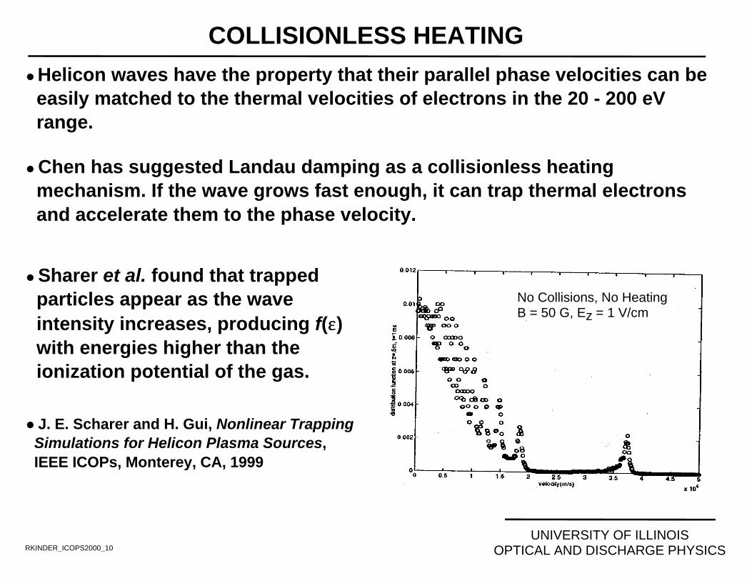
l Helicon waves have the property that their parallel phase velocities can be easily matched to the thermal velocities of electrons in the 20 - 200 eV range.
l Chen has suggested Landau damping as a collisionless heating mechanism. If the wave grows fast enough, it can trap thermal electrons and accelerate them to the phase velocity.
COLLISIONLESS HEATING
RKINDER_ICOPS2000_10
l Sharer et al. found that trapped particles appear as the wave intensity increases, producing f(εε) with energies higher than the ionization potential of the gas.
l J. E. Scharer and H. Gui, Nonlinear Trapping Simulations for Helicon Plasma Sources, IEEE ICOPs, Monterey, CA, 1999
No Collisions, No HeatingB = 50 G, Ez = 1 V/cm

UNIVERSITY OF ILLINOISOPTICAL AND DISCHARGE PHYSICSRKINDER_ICOPS2000_11
COLLISIONLESS HEATING
ll Ar, 10 mTorr, 1 kW, 50 sccm
l The electron energy distribution (EED) was obtained from the EMCS.l The tail of the EED is peaked near the coils.l As the magnetic field is increased there is an increase in the high energy tail downstream.
1
10-8
40
0
ENERGY (eV)400
B = 20 G
302010ENERGY (eV)
40
RADIALLY AVERAGED EED
B = 150 G
302010ENERGY (eV)
40
B = 300 G
302010

UNIVERSITY OF ILLINOISOPTICAL AND DISCHARGE PHYSICSRKINDER_ICOPS2000_12
COLLISIONLESS HEATING
l Ar, 1 kW, 50 sccm, 300 G
l As the pressure is decreased, the collisionless heating mechanisms become more dominant.
l There is significant heating in the downstream region.
1
10-8
40
0
ENERGY (eV)400 302010
ENERGY (eV)40
RADIALLY AVERAGED EEDF
P = 5 mTorr
302010ENERGY (eV)
40
P = 10 mTorr
302010
P = 2 mTorr

UNIVERSITY OF ILLINOISOPTICAL AND DISCHARGE PHYSICSRKINDER_ICOPS2000_13
COLLISIONLESS HEATING
l Ar, 1 kW, 300 G, 2mTorr
l The tail end of the EEDF increases with increasing distance from the coil.
l The axial component of the electromagnetic field is responsible for most of the power deposition.
0.5 0.005
0.44.0 V/cm
W/cm-3
IncreasingDistanceFrom Coil
0 10 20 30 40 50
100
10-2
10-4
10-6
Energy (eV)
PowerDeposition Axial Field

COLLISIONLESS HEATING : TG MODE
RKINDER_ICOPS2000_14
University of Illinois Optical and Discharge Physics
εερ enq
E∆
==⋅∇ ( )ωω
σ
i
q
E
nDamp
e
+
⋅⋅∇−
=∆
• Recently it has been suggested (Chen) that much of the electronheating comes from the electrostatic component of the heliconwave (i.e. the Trivelpiece Gould (TG) mode).
• If plasma neutrality is not enforced, the divergence term in thewave equation must be included. Effects of the electrostatic TGmode can then be resolved.
! The divergence of the electric field is where, equal to the perturbed electrons.
EiEEE ⋅−=
∇⋅∇−
⋅∇∇ σωεω
µµ 211
TG Wave Helicon Wave

UNIVERSITY OF ILLINOISOPTICAL AND DISCHARGE PHYSICS
TG MODE AND ELECTRON DENSITY
ll Ar, 10 mTorr, 1 kW, 50 sccm
l The gradient of the perturbed electrons, represents a current sink due to the TG mode.
l As the magnetic field increases, the TG mode is strongly damped near the surface with a less penetration in the plasma volume.
35
0015 15
RADIUS (cm)
B = 50 G B = 100 G B = 200 G
Fraction5 x 10-7
(cm-3)
5 x 10⁻⁹
∆ne / ne [e] ∆ne / ne [e] ∆ne / ne [e]
2.5 x 10112.5 x 1012RKINDER_ICOPS2000_15

UNIVERSITY OF ILLINOISOPTICAL AND DISCHARGE PHYSICS
TG MODE AND POWER DEPOSITION
l Ar, 10 mTorr, 1 kW, 50 sccm
l At low magnetic fields, the TG mode is weakly damped and is strongly coupled to the helicon wave, therby penetrating into the plasma volume.
l As the magnetic field increases, the TG mode is strongly damped near the surface and power deposition occurs closer to the surface.
Fraction5 x 10-7
2 0.02W / cm-3
5 x 10⁻⁹
35
0015 15
RADIUS (cm)
B = 50 G B = 100 G B = 200 G
WO/TG W/TGWO/TG W/TG WO/TG W/TG
RKINDER_ICOPS2000_16

UNIVERSITY OF ILLINOISOPTICAL AND DISCHARGE PHYSICS
RKINDER_ICOPS2000_17
CONCLUSIONS
l Simulations of a m = 0 mode were conducted in a commercial helicon plasma tool. In the absence of the TG mode, with increasing B-field, electric field propagation progressively follows B-field lines and significant power can be deposited downstream.
l Electron Monte Carlo Simulations have shown an increase in the tail of the EEDs in the downstream region indicating some amount of collisionless heating.
l Volumetric power deposition is ultimately limited by damping of the TG mode and the helicon wavelength. Wave propagation can be suppressed in electronegative gas mixtures in the low power - high B-field range, where the wavelength exceeds the chamber dimension.
l Investigations on the dependence of the TG mode must be established to understand the coupling of electromagnetic field and power deposition to the plasma.