heavy duty digger - speecospeeco.com/whitepapers/heavy_duty_digger(24046000).pdf · page 1 warning:...
TRANSCRIPT

ASSEMBLY & OPERATING INSTRUCTIONSTHIS SAFETY ALERT SYMBOL IDENTIFIES IMPORTANT SAFETY MESSAGES IN THIS MANUAL.FAILURE TO FOLLOW THIS IMPORTANT SAFETY INFORMATION MAY RESULT IN SERIOUSINJURY OR DEATH.
PD37-719-0608Rev 2
OWNER’S MANUAL
HEAVY DUTYPOST HOLE DIGGER
MODEL NO. 24046000

Table of Contents
Page(s)
Important Safety Information ................................................................................................ 1-4
Intended Use .............................................................................................................. 1
Personal Protective Equipment ................................................................................. 1
Safety Decals ............................................................................................................. 1-3
General Safety and Preparation ................................................................................. 3
Operating Safety ......................................................................................................... 3-4
Repair and Maintenance Safety .................................................................................. 4
Assembly Instructions ............................................................................................................ 5
General Maintenance ............................................................................................................. 6
Operating Instructions ............................................................................................................ 6..
Parts List ................................................................................................................................. 7
Parts Breakdown Illustration ................................................................................................... 8
Cutting Edges and Point Parts List ......................................................................................... 9
Driveline Parts List ................................................................................................................... 10
Notes ........................................................................................................................................ 11
Specifications ...................................................................................................................... Back Cover
Ordering Information ........................................................................................................... Back Cover

Page 1
WARNING: Read and thoroughly understand all instructions and safety information before assembling oroperating this post hole digger Failure to do so may cause serious injury or death. Do not allow anyoneto operate this post hole digger who has not read this manual. As with all power equipment a post holedigger can be dangerous if assembled or used improperly. Do not operate this post hole digger if youhave doubts or questions concerning safe operation. Call our customer service department at 1-800-525-8322 to address these concerns.
Si no entiende ingles, se prefiere que busque alguien que interprete las instrucciones para usted.
INTENDED USE
This product is designed to dig holes in the soil when attached to the 3-point linkage system and power-take-off of a tractor.
It is not intended for any other use. Using the product for anything other than digging holes could result in serious injury ordeath.
PERSONAL PROTECTIVE EQUIPMENT
ALWAYS use appropriate personal protective equipment such as protective eyewear, earware, gloves, safety shoes and hardhat when operating this post hole digger.
NEVER wear loose clothing or jewelry that could become entangled in the auger or driveline.
SAFETY DECALS
ALWAYS replace missing or defaced decals. Reorder from SpeeCo, Inc., 15000 W. 44th Ave., Golden, CO 80403 or call1-800-525-8322.
LOCATION: FRONT OF GEAR BOXPART NUMBER: 52022000
LOCATION: SIDE OF GEAR BOXPART NUMBER: 52045600

Page 2
LOCATION: BOOMPART NUMBER: 52033300
LOCATION: PTO DRIVE SHAFT SHIELDPART NUMBER: 52046100
LOCATION: PTO DRIVE SHAFT UNDER SHIELDORDER DECAL KIT: 52044100
NOTE: IF THE DRIVE SHAFT GUARDMENTIONED IN THE ABOVE DECAL ISMISSING ,YOU MUST ORDER AREPLACEMENT BY CALLING USAT 1-800-525-8322.
LOCATION: TOP END OF BOOM ON GEAR BOX END
ORDER DECAL KIT: 52050500

Page 3
LOCATION: TOP END OF AUGER TUBEPART NUMBER: DL52020500
NOTE: IF THE OUTPUT SHAFT GUARD MENTIONED IN THE ABOVE DECAL IS MISSING ,YOU MAY ORDER A REPLACEMENT BY CALLING US AT 1-800-525-8322.
GENERAL SAFETY AND PREPARATION
ALWAYS make sure that anyone else who operates this post hole digger has read and understood the contents of theowner’s manual and all safety decals on the product.
ALWAYS be certain that all members of the work party are familiar with the operation of the digger and the hazardsassociated with it.
ALWAYS check with authorities for underground utilities before digging a hole. Serious injury or death could result fromcontact with gas or electric lines.
ALWAYS check the tractor owner’s manual for instructions on operation, attachment of 3-point equipment and safety.
ALWAYS make sure that all safety shields are in place and tightened down. Do not operate this post hole digger if anyshields are missing. Contact SpeeCo, Inc. at 1-800-525-8322 for replacement part(s).
ALWAYS make sure that the auger point and cutting edges are intact and in good working order before using this digger.
NEVER allow children or other persons to ride on the Tractor or Implement. Falling off can result in serious injury or death.
NEVER allow children to play on or around Tractor or Implement. Children can slip or fall off the Equipment and be injuredor killed. Children can cuase the Implement to shift or fall crushing themselves or others.
NEVER allow others within 20 feet while operating the post hole digger.
NEVER operate post hole digger without all guards in place.
ALWAYS ensure the driveline is securely locked onto the PTO.

REPAIR AND MAINTENANCE SAFETY
OPERATING SAFETY
ALWAYS operate this post hole digger from the tractor seat.Only one person should operate the digger.
NEVER attach the post hole digger with the tractor engine running.
NEVER operate the post hole digger with anyone near or in contact with any part of the implement, PTO driveline or auger.Serious injury or death could result from entanglement with moving parts.
ALWAYS make sure that the tractor brake is set before digging a hole.
ALWAYS keep hands, feet and clothing away from power-driven parts during operation.
NEVER manually position the auger or manually force the auger into the ground.
ALWAYS make sure that the tractor engine is shut off and the PTO drive is disengaged before leaving the tractor seat.
NEVER move the tractor with the power-take-off in the ON position.
NEVER exceed 540 RPM PTO operating speed.
NEVER operate the post hole digger when the auger point is more than 6 in. above ground level. Operating the digger inelevated positions may cause the PTO driveline “U” joints to bind resulting in equipment damage and operator injury.
ALWAYS turn off the digger immediately if an immovable object is encountered to prevent damage to the gear box ordriveshaft and possible injury. A shear bolt is provided but may become welded to the input shaft if the driveshaft is leftrunning after being sheared.
.TRANSPORTATION SAFETY
NEVER allow anyone to ride on Implement.
Make certain the slow moving (SMV) sign and other reflectors are clearly visible. Follow local traffic codes for slow movingvehicles when transpotting on public roads.
ALWAYS perform maintenance operations such as lubrication, adjustments or repairs on the post hole digger with thetractor engine off, the PTO drive disengaged and the auger point resting on the ground.
ALWAYS use the correct shear bolt (Grade 5). NEVER use or replace the shear bolt with one that is longer than the onespecified in the manual (5/16” x 2-1/2”).
Periodically inspect all moving parts for wear and replace when necessary with authorized service parts. Look for loosefasteners, worn or broken parts, and leaky or loose fittings. Serious injury may occur from not maintaining this machine ingood working order.
Do not modify or alter this Implement. Do not permit another to modify or alter this Implement, any of itscomponents or any Implement function. Any modification will void the warranty.
Page 4

IMPORTANT: The gear box is shipped without lubricant. Fill the top hole with 80W-90 lubricant or the equivalent.Approximately 1.75 quarts of the lubricant is enough to lubricate the gears and bearings. Agreater amount will not harm the gear box. Do not fill to overflow point as this may damage theseals.
STEP 1: Be certain that the gear box has adequate lubrication. Check the oil level after every fifty hours ofuse.
STEP 2: Attach the boom (1) to the top link mounting bracket on the tractor using a top link pin and alynch pin (not provided) through the swivel ball at the bottom of the boom. The ball acceptseither category 1 or 2 pins.
STEP 3: Connect the “A” frame (5) to the tractor’s 3-point lift arms using the 7/8 in. pull pins with nut andlockwasher (7) as shownin the drawing. Attach the “A” frame (5) to the boom (1) after selectingthe desired hole (for angle adjustment) using the “A” frame pin (6) and lynch pin (4).
STEP 4: Attach the gear box (10) to the boom (1) using the boom pin supplied with the gear box. When inplace secure with the cotter pins provided. NOTE: Input shaft shield (9) and output shaft shield(8) are already attached to the gear box.
STEP 5: Attach the auger (18,19,20, 25 or 26 ) to the output shaft on the bottom of the gear box (10) usingthe 1/2 in. hex cap screws (15), 1/2 in. lockwashers (16) and 1/2 in. hex nuts (17). Tighten thenuts.
STEP 6: Attach the driveline (11) to the gear box input shaft using the 3/8 in.grade 5 hex cap screw (12),the 3/8 in.lockwasher (13) and the 3/8 in. NC hex nut (14). Tighten the hex nut. Insert the 1/4in. x 3/8 in. set screw (24) from the hardware kit in the hole on the yoke that aligns with the 3/16in. groove on the gear box input shaft. Tighten loosely.
ATTENTION: THE 3/8 IN. HEX CAP SCREW PROVIDES SHEAR PROTECTION. USE A GRADE 53 IN. BOLT ONLY TO AVOID DAMAGE TO THE GEAR BOX OR AUGER.
IMPORTANT: The universal joint should be greased with a good grade chassis lube every week. At thebeginning of each season grease the sliding driveshaft members with a moly grease. Alldiggers are equipped with quick-detach universal joints on the power-take-off end for a1-3/8 in. splined shaft.
STEP 7: Attach the tractor end of the driveline (11) to the tractor PTO shaft. Push in the spring-loaded pinin the splined yoke and slip it on the splined PTO shaft of the tractor. Release the pin and pushuntil it locks securely in place. It will be necessary to obtain a 1-1/8 in. to 1-3/8 in. sleeve splineadapter if your tractor PTO shaft has a 1-1/8 in. spline.
STEP 8: Attach and secure the lower chain on the driveline to the boom (1). Attach the upper chain to thehole on the gear box shield (9).
STEP 9: Check all nuts and bolts for tightness. Stabilizers should be kept tight to avoid side sway of thedigger.
NOTE: See illustration A for reference in assembling the digger and mounting it to the tractor. Note thatthe boom angle can be adjusted on your tractor for proper digging and ground clearance bymoving the “A” frame to a different mounting hole as shown in illustration B.
NOTE: When the 7/8 in. diameter pull pins in the “A” frame are too small for the holes in the lift arms,bushings should be used to obtain a proper fit
Page 5
ASSEMBLY INSTRUCTIONS
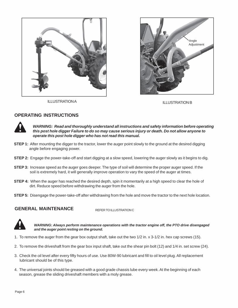
ILLUSTRATION B
REFER TO ILLUSTRATION C
1. To remove the auger from the gear box output shaft, take out the two 1/2 in. x 3-1/2 in. hex cap screws (15).
2. To remove the driveshaft from the gear box input shaft, take out the shear pin bolt (12) and 1/4 in. set screw (24).
3. Check the oil level after every fifty hours of use. Use 80W-90 lubricant and fill to oil level plug. All replacement lubricant should be of this type.
4. The universal joints should be greased with a good grade chassis lube every week. At the beginning of each season, grease the sliding driveshaft members with a moly grease.
OPERATING INSTRUCTIONS
STEP 1: After mounting the digger to the tractor, lower the auger point slowly to the ground at the desired digging angle before engaging power.
STEP 2: Engage the power-take-off and start digging at a slow speed, lowering the auger slowly as it begins to dig.
STEP 3: Increase speed as the auger goes deeper. The type of soil will determine the proper auger speed. If the soil is extremely hard, it will generally improve operation to vary the speed of the auger at times.
STEP 4: When the auger has reached the desired depth, spin it momentarily at a high speed to clear the hole of dirt. Reduce speed before withdrawing the auger from the hole.
STEP 5: Disengage the power-take-off after withdrawing from the hole and move the tractor to the next hole location.
GENERAL MAINTENANCE
OPERATING INSTRUCTIONS
WARNING: Always perform maintenance operations with the tractor engine off, the PTO drive disengagedand the auger point resting on the ground.
WARNING: Read and thoroughly understand all instructions and safety information before operatingthis post hole digger Failure to do so may cause serious injury or death. Do not allow anyone tooperate this post hole digger who has not read this manual.
AngleAdjustment
Page 6
Angle Adjustment
ILLUSTRATION A

ECNEREFERREBMUN
TRAPREBMUN NOITPIRCSED
REBMUNDERIUQER
00064042 reguAsselreggiDeloHtsoPytuDyvaeH 11 00168042 mooB 12 00957042 niPxoBraeG/mooB 14 L/O niPhcnyL.ni61/7 15 00068042 emarF"A" 16 00107070 niPemarF"A" 17 00802070 rehsawkcoLdnatuNhtiwniPlluP.ni8/7 28 00357042 drauGtuptuOxoBraeG 19 00257042 drauGtupnIxoBraeG 101 00457042 sdleihS/wxoBraeG 111 ZH051142 dleihScitsalPhtiwenilevirD 1A11 00171142 ylbmessAdrauGenilevirD 1B11 00021142 ekoYniPhsuP 1C11 ZH951142 ekoYdnEtnemelpmI 1D11 ZH551142 tiKgniraeBdnassorC 2E11 L/O wercSteSdetnioP"8/3x"4/1 1
21 L/OraehS5edarG(wercSpaCxeH.ni3x.ni8/3
)tloB 131 L/O rehsawkcoL.ni8/3 141 L/O tuNxeHCN.ni8/3 151 L/O wercSpaCxeH.ni3xCN.ni2/1 261 L/O rehsawkcoL.ni2/1 271 L/O tuNxeHCN.ni2/1 281 00112142 reguA.ni6 191 00412142 reguA.ni9 102 00712142 reguA.ni21 132 00912142 tnioPwercS 142 L/O wercSteS.ni8/3x.ni4/1 152 00845042 reguA.ni81 162 00945042 reguA.ni42 1
.serotsmrafdnaerawdrahhguorhtelbaliavasrenetsafnommoC.yllacolniatbO-L/O
MODEL POST HMRTS BREAKDOWN
Page 7
HEAVY DUTY POST HOLE DIGGERPARTS BREAKDOWN
NOTE: All augers are sold separately.

HEAVY DUTY DIGGER
ILLUSTRATION C
Page 8

Page 9
NOTE: It is important to replace the point and cutting edges when they show signs of excessive wear.
CUTTING EDGES AND POINT PARTS BREAKDOWN
O/L- Obtain locally. Common fasteners available through hardware and farm stores.
ILLUSTRATION D
*NOTE:The number of cutting edges varies by auger size. Check your augerwhen ordering replacement cutting edges. See information below.
1
2
3
4
5
6
6 inNumber of Cutting Edges Per Auger
6 in. (24121100)- 2 9 in. (24121400)- 2 12 in.(24121700)- 4 18 in.(24054800)- 4 24 in.(24054900)- 6
in. auger (
ECNEREFERREBMUN
TRAPREBMUN NOITPIRCSED
REBMUN*DERIUQER
1 00222112 egdEgnittuCedibraC reguaybseirav
2 L/O tloBegairraCCNU"1x"2/1 egdegnittucrep1
3 L/O tuNkcoLCNU"2/1 egdegnittucrep1
4 L/O tloB"2/1-3x"2/1 1
5 L/O tuNkcoL"2/1 1
6 00912142 tnioPreguA 1

Page 11
NOTES
Model No. ____________________
Date of Purchase _______________ Place of Purchase _______________________ _______________________ _______________________ _______________________

SPECIFICATIONS
ORDERING INFORMATION
yrogetaCrotcarT 2yrogetaCdna1yrogetaC
xoBraeG raeghcaefosedishtobnosgniraebrellorderepatdnasraegnoinipyollalaicepS
enilevirD )dedleihsyletelpmoc(OTPenilps-6dradnatstifotekoyhcat-kciuqhtiwdeppiuqE
sreguA )yletarapesdlos(.ni42dna.ni81,.ni21,.ni9,.ni6
segdEgnittuC )yletarapesdlos(edibrac,elbaecalpeR
tnioP )yletarapesdlos(pitlaripSmooB thgiehrofselohelpitlumdnabirderepathtiwgnibuthtgnertshgih.D.O.ni.ni4/1-3
tnemtsujda
emarf-A gnibuthtgnertshgih.ni4/1-3
sdleihsytefaS tfahstuptuoxobraegdnatnioj"U"xobraeg,enilevirdnO
tloBraehS .sraegdnaregua,enilevirdtcetorpottfahstupninO.elbaecalpeR
snoitpO tikgnitnuomthgiewdnatikecrofnwodciluardyH
TRAPREBMUN NOITPIRCSED
00064042 reguasselreggidelohtsopytuDyvaeH
00112142 segdegnittucedibracelbaecalperdnatnioplaripshtiwregua.ni6
00412142 segdegnittucedibracelbaecalperdnatnioplaripshtiwregua.ni9
00712142 segdegnittucedibracelbaecalperdnatnioplaripshtiwregua.ni21
00845042 segdegnittucedibracelbaecalperdnatnioplaripshtiwregua.ni81
00945042 segdegnittucedibracelbaecalperdnatnioplaripshtiwregua.ni42
00912142 sregua.ni42dna.ni81,.ni21,.ni9,.ni6roftnioplaripS
00222142 sregua.ni42dna.ni81,.ni21,.ni9,.ni6rofegdegnittucedibrac.ni2).ezisreguaybseiravderiuqerytitnauQ(
00568042 tiKtnuoMthgieW
00654042 tikecrofnwodciluardyH
