heavy-duty escalator design guidelines · escalator design, materials, construction clearances,...
TRANSCRIPT
A P T A S T A N D A R D S D E V E L O P M E N T P R O G R A M
RECOMMENDED PRACTICE
American Public Transportation Association
1300 I Street, NW, Suite 1200 East, Washington, DC 20006
APTA RT-EE-RP-001-02, Rev. 3
First Published: 2002
First Revision: July 26, 2004
Second Revision: 2011
Third Revision: June 7, 2019
Elevator & Escalator Technical Forum
Working Group
This document represents a common viewpoint of those parties concerned with its provisions, namely operating/ planning agencies, manufacturers, consultants, engineers and general interest groups. The application of any standards, recommended practices or guidelines contained herein is voluntary. In some cases, federal and/or state regulations govern portions of a transit system’s operations. In those cases, the government regulations take precedence over this standard. The North American Transit Services Association (NATSA) and its parent organization APTA recognize that for certain applications, the standards or practices, as implemented by individual agencies, may be either more or less restrictive than those given in this document.
© 2019 NATSA and its parent organization. No part of this publication may be reproduced in any form, in an electronic retrieval system or otherwise, without the prior written permission of NATSA.
Heavy-Duty Escalator Design Guidelines Abstract: This Recommended Practice contains guidelines for transit systems to use to specify heavy-duty
escalators for use in a transit environment.
Keywords: escalators, heavy-duty escalators, transit escalators
Summary: This design guideline is the result of the combined efforts of the members of the APTA Elevator
and Escalator Technical Forum over the past several years. The objective is to address the specific heavy-duty
escalator needs of North American transportation systems. It is intended as a guideline of technical provisions
for the design and construction of escalators that can provide safe, reliable service in the harsh, heavy-usage,
high-abuse environment of transportation systems. Membership of the Technical Forum includes
transportation systems, consultants and escalator/component manufacturers.
Scope and purpose: This design guideline is not intended to be a 100 percent ready technical specification
for all transportation systems. Transit agencies may find it necessary to make changes to suit their specific
needs. However, the stringent provisions are the result of the members’ combined experiences and, in general,
reflect transportation requirements and the need for improved safety and reliability. There are also notes and
comments in the text to guide the user in preparation of a procurement specification document.
© 2019 American Public Transportation Association | ii
Table of Contents
Participants .................................................................................................................................................. iii Introduction ................................................................................................................................................. iv
1. General conditions ........................................................................................................................................ 1 1.1 Applicable codes, standards and publications .................................................................................... 1 1.3. Submittals ........................................................................................................................................... 1 1.4. Operating and maintenance manuals .................................................................................................. 3 1.5. Training .............................................................................................................................................. 5 1.6. Quality assurance ................................................................................................................................ 5 1.7. Temporary use .................................................................................................................................... 7 1.8. Delivery, storage and handling ........................................................................................................... 7 1.9. Spare parts and special tools ............................................................................................................... 7 1.10. Warranty ............................................................................................................................................. 8 1.11. Maintenance service ........................................................................................................................... 9 1.12. Design criteria ..................................................................................................................................... 9 1.13. Environmental requirements ............................................................................................................. 10 1.14. Protection requirements .................................................................................................................... 10 1.15. Coordination ..................................................................................................................................... 11
2. Products ...................................................................................................................................................... 12 2.2. General.............................................................................................................................................. 12 2.3. Controls and safety devices .............................................................................................................. 12 2.4. Materials ........................................................................................................................................... 15 2.5. Finishes ............................................................................................................................................. 16 2.6. Mechanical equipment ...................................................................................................................... 16
3. Execution .................................................................................................................................................... 22 3.1 Installation ........................................................................................................................................ 22 3.2 Field testing ...................................................................................................................................... 22
4 Applicable codes, standards and publications ....................................................................................... 23
Definitions ................................................................................................................................................... 24
Abbreviations and acronyms .................................................................................................................... 25
Summary of document changes............................................................................................................... 26
Document history ....................................................................................................................................... 26
© 2019 American Public Transportation Association | iii
Participants
The American Public Transportation Association greatly appreciates the contributions of Jason Arndt, Gary
Bergstresser, Ed LaGuardia, Tom Hausenhauer, Dave Hansen, Dennis Rager, Sean Steiner, and Mark
Yako, who provided the primary effort in reviewing and revising this document.
At the time this standard was completed, the working group included the following members:
Edward La Guardia, Michael Baker International, Chair
Lonnie Murray, AMTRAK, Vice Chair
Brent Andrews, KONE
Jason Arndt, Gannett Fleming
Charles Austin, Regional Transportation District
Lena Babayan, LA Metro
Charles Banks, KONE
Philippe Bellon, Metrolinx
Gary Bergstresser, SEPTA
Dave Bobbitt, PATH
Gerald Clark, BART
Robbie Cotton, BART
Donald Desaulniers, STM Montréal
James Dunn, BART
Brian Emch, Port Authority of NY & NJ
David Evans, Schindler Elevator
Hussein Farah, LA Metro
Nikole Gore-Layton, Elevator Escalator Safety
Allen Grasser, CTA
Svetlana Grechka, Regional Transportation District
David Guerin, WMATA
David Hansen, Gannett Fleming
Tom Hausenbauer, MEI Total Elevator Solutions
Herman Hausmann, NYC Transit
Dean Heasley, Kings III
Rick Herndobler, CTA
Donald Iannuzzi, NYC Transit
Vernon Irving, WMATA
Thomas Kenny
Robert Keylon, MTA Long Island Rail Road
Jim Kinahan, Michael Baker International
Madhavan Kozhipurath, WMATA
David Lacosse, WMATA
Norm Langerhorst, BC Rapid Transit
John Lennon, CTA
Nick Lombardi, Spartan Solutions
Denise Longley, LA Metro
Kevin Loughnane, CTA
Carlos Martinez, LA Metro
Colleen May, SEPTA
Scott McAleese, CTA
Pamela McCombe, WSP USA
David Medley, WMATA
Mitch Nici, WMATA
Kate O’Connor, SEPTA
Robert O’Connor, CTA
John Oricchio, NYC Transit
Howard Peer, Parsons Corp.
William Peters, MARTA
Rosa Rankin, SFMTA
Jerry Robinson, Castrol Industrial North America
Steve Romnes, MEI-Total Elevator Solutions
Matthew Rubi, LA Metro
Harjeet Singh, Miami-Dade Transit
Richard Smith, Regional Transportation District
Dave Springer, DART
Sean Steiner, Gannett Fleming
Antonio Suarez, NYC Transit
Patrick Tang, NYC Transit
Michael Venuto, Port Authority Transit Corp.
Cedric Watson, WMATA
Tom Williams, Texas A&M Transportation Institute
Dirk Winkelhake, Otis Elevator
George Younger, BART
Project team
Charles Joseph, American Public Transportation Association
Marie Benton, American Public Transportation Association
© 2019 American Public Transportation Association | iv
Introduction
This introduction is not part of APTA RT-EE-RP-001-02, Rev. 3, Heavy-Duty Escalator Design Guidelines.
This design guideline is the result of the combined efforts of the members of the APTA Elevator and
Escalator Technical Forum and its Working Group over the past several years. The objective is to address the
specific heavy-duty escalator needs of North American transportation systems. It is intended as a guideline of
technical provisions for the design and construction of escalators which can provide safe, reliable service in
the harsh, heavy usage, high abuse environment of transportation systems. Membership of the Technical
Forum and its Working Group includes transportation systems, consultants, and escalator/component
manufacturers.
This design guideline is not intended to be a 100 percent technical specification for all transportation systems.
Each Owner may find it necessary to make changes to suit their specific needs. However, the stringent
provisions are the result of the members combined experiences and, in general, reflect transportation
requirements and the need for improved safety and reliability. There are also “comments” in the text to guide
the user in preparation of a procurement specification document.
It is expected that some these requirements will “add to the cost of the procurement.” Past experience shows
that there is a high life cycle maintenance cost associated with the manufacturer’s “standard” product when
used in a transportation environment. Paying “more up front” will be more than compensated by the overall
reduced life cycle costs. Most importantly, it will improve customer safety, satisfaction, and convenience. The
results can only be an increase in the public’s confidence in a transportation system’s ability to meet their
needs, and thus, an increase in ridership.
APTA RT-EE-RP-001-02, Rev. 3 Heavy-Duty Escalator Design Guidelines
© 2019 American Public Transportation Association Page 1 of 26
Heavy-Duty Escalator Design Guidelines
1. General conditions
NOTE TO SPECIFIER: Clear instructions must be defined in the general terms and conditions relating to the installer being ready for the inspection, as well as the Owner being ready for items such as emergency power testing, fire alarm and smoke detector testing and communications. Special consideration should be given to AHJ lead times to schedule acceptance tests.
This section specifies requirements for design, fabrication, installation and testing of heavy-duty
escalators. Language from this design guideline may be incorporated directly into the technical
specification in order to be binding. In the event of a conflict between any APTA referenced
standards or recommended practices and the agency’s specification, the agency’s technical
specification should prevail.
1.1 Applicable codes, standards and publications
Escalator design, materials, construction clearances, workmanship and test should conform to the
requirements of the codes and regulations and should be listed. Any additional requirements imposed
by local agencies should be incorporated into the escalator design specifications.
1.2. Temporary and permanent electrical power services
A. Temporary power for installation should be made available to the Installer at the time of the
installation. Permanent power should be made available for testing. All power should be provided
at no cost to the Installer.
B. For the escalator drive systems: 208, 220 or 480 V, three-phase, three-wire, 60 Hz terminating in
a disconnect switch within sight of the controller. Coordination is required between the electrical
contractor and escalator contractor.
C. For lighting and ground fault circuit interrupter (GFCI) receptacles: 120 V, one-phase, three-wire,
60 Hz terminating at the escalator controller location.
D. Separate disconnect for balustrade lighting, comb plate heater and pit/truss heaters.
1.3. Submittals
A. Product data:
Submit manufacturer’s product data within four weeks of Notice to Proceed (NTP) for each
system proposed for use. Include as a minimum the following:
1. Electrical characteristics and connection requirements.
2. Expected heat dissipation of escalator equipment in controller room. BTU based on
twenty-four (24) hours per day, seven (7) days per week.
3. Direction of travel shall be considered as either direction, or the unit shall be up and
down reversible.
B. Maintenance programs:
Within 60 days after NTP, and prior to installation, the Contractor should submit detailed interim
and revenue service maintenance programs, showing functions to be performed and their
scheduled frequency.
APTA RT-EE-RP-001-02, Rev. 3 Heavy-Duty Escalator Design Guidelines
© 2019 American Public Transportation Association Page 2 of 26
D. Coordinated delivery schedule.
D. Manufacturer’s recommended preventive maintenance plan, including interim maintenance
procedures where applicable.
E. Pre-acceptance test forms.
F. Shop drawings:
Submit six (6) copies of approval layouts to scale and complete in their entirety. Shop drawings
should be in Metric and Imperial Measurements. Drawings should be submitted for each escalator
and should include but not limited to the following:
i) Facsimile outline of escalator truss in profile and plan
ii) Facsimile elevation of escalator balustrade
iii) Vertical section through balustrade
iv) Truss midway between working points
v) Escalator data includes escalator types, load and electrical data
NOTE TO SPECIFIER: Determine whether shop drawings should be on paper or in a digital format acceptable to the Client.
G. Scale drawings:
NOTE TO SPECIFIER: Scaled drawings should show all relevant structural elements.
Scaled drawings should show detail drawings for each escalator type and should include but not
limited to the following:
1. Truss stanchion
2. Track system and supports
3. Drive system
4. Step nosing radius at upper and lower ends
5. Drive chains and gear train
6. Step chain or step links (including chain pitch, step and trailer wheels)
7. Step assembly (including axle, step tread, frame and riser)
8. Handrail system (including profile, guides, drive and tension device)
9. Support details (including upper, lower, intermediate and slip joint), balustrade deck cover,
interior panels, skirt panels and their moldings
10. Safety switches and operating devices
11. Motor and emergency brakes
12. Floor plates
13. Speed encoder
14. Metal gauges
15. Radial, vertical and horizontal dimensions required for manufacture, and positions of lower
and upper working points
16. Attachment of truss to structure
17. Major mechanical and electrical components within truss
18. Drainage and electrical interfaces
19. Ceiling intersection guards
20. Passenger instruction signs
21. Emergency stop button
22. Operating panel in upper and lower balustrades (including stop button, start and direction
selection switches, and fault finder receptacle)
23. All bearing ratings, identification and catalog numbers should be provided.
APTA RT-EE-RP-001-02, Rev. 3 Heavy-Duty Escalator Design Guidelines
© 2019 American Public Transportation Association Page 3 of 26
24. Complete schematic diagram should be provided for the controller and all electrical devices
and a detailed drawing depicting the controller component layout and component
identification
25. Coordinated machine/controller room layout drawing
26. Test certificates for step chain should be provided for approval
27. Test certificates for step assemblies shall be provided for approval
28. Test certificate for step fatigue test
H. As-built drawings should as a minimum show the following: NOTE TO SPECIFIER: The contract should identify a specific time frame within the contract limits for the contractor to supply the required as-built drawings for each individual unit.
1. Truss stanchion
2. Track system and supports
3. Drive system
4. Step nosing radius at upper and lower ends
5. Drive chains and gear train
6. Step chain or step links (including chain pitch, step and trailer wheels)
7. Step assembly (including axle, step tread, frame and riser)
8. Handrail system (including profile, guides, drive and tension device)
9. Support details (including upper, lower, intermediate and slip joint), balustrade deck cover,
interior panels, skirt panels and their moldings
10. Safety switches and operating devices
11. Motor and emergency brakes
12. Floor plates
13. Speed encoder
14. Metal gauges
15. Radial, vertical and horizontal dimensions required for manufacture, and positions of lower
and upper working points
16. Attachment of truss to structure
17. Major mechanical and electrical components within truss
18. Drainage and electrical interfaces
19. Ceiling intersection guards
20. Passenger instruction signs
21. Emergency stop button
22. Operating panel in upper and lower balustrades (including stop button, start and direction
selection switches, and fault finder receptacle)
I. Maintenance programs
1. Prior to installation, installer should submit detailed interim and revenue service maintenance
programs, showing functions to be performed and their scheduled frequency.
2. Where applicable, part of the submittal package shall include a maintenance control plan.
1.4. Operating and maintenance manuals
NOTE: Due to the critical nature of Operations and Maintenance (O&M) Manuals, it is recommended
that this item be itemized in the project schedule of values.
A. Prior to installation, the Installer should submit three preliminary sets of operation and
maintenance (O&M) manuals for approval six weeks after NTP. After Owner approval and prior
to the beginning of acceptance testing, one set of the approved manuals should be provided by the
APTA RT-EE-RP-001-02, Rev. 3 Heavy-Duty Escalator Design Guidelines
© 2019 American Public Transportation Association Page 4 of 26
Installer as well as one copy in an electronic format approved by the Owner. After approval and
substantial completion, the final manuals are due no more than 30 days after any punch list items
are completed.
The manuals should include the following:
1. Complete table of contents
2. Complete instructions regarding operation and maintenance of equipment including
disassembly and assembly of drive system, handrail drive assembly and track system.
Included will be complete illustrated, exploded views of all assemblies and a complete,
illustrated, exploded view for identifying all system parts.
3. Complete nomenclature, lead time and location of replaceable parts, OEM and installer part
numbers, current cost, and source. If the product source is another vendor, the
Installer/Contractor should include the name and address of the other vendor.
4. Approved preventive maintenance plan and schedule.
5. Descriptions and locations of safety devices.
6. Safety rules, tests and procedures, including testing of all systems and subsystems.
7. Procedures for adjusting brake, handrail tension, handrail chain drive tension, step chain
tension, track system, and mechanical components, including pictorials.
8. Instructions for removing floorplate, replacing comb segments, and removing and installing
steps and interior panels.
9. Troubleshooting techniques and flow charts for all systems.
10. Detailed lubrication and cleaning schedule indicating weekly, monthly, quarterly, semiannual
and annual lubrication; and a description of each lubrication point, lubrication type and
specification.
11. Provide (one) line diagrams that shows the utility power service to each disconnect switch.
12. Provide schematic control drawings and manuals and job specific software.
13. As-built drawings should include the following:
i) Control and schematic electrical wiring diagrams of the controller, including wiring of
safety devices to connections with remote indication and control panels for each escalator
and group of escalators.
ii) Electrical layout showing the placement of lighting, light switches, receptacles, light
fixtures, disconnect switches, and convenience outlets in machinery and controller spaces
and pits.
iii) Complete detailed drawings and wiring diagram of escalator fault-finding device and
connection to annunciator panel.
iv) Electronic and hard copies of ladder diagrams, logic and program.
B. Certification
1. The OEM should provide to the Owner certification that the Owner of the escalator(s) should
be provided with copies of all documents related to maintenance, safety, operations, design
changes, modifications, retrofits, etc., that relate to any part, component, equipment, system,
subsystem, or material and services applicable to the escalators(s) provided.
2. All of the above referenced should be provided by the Installer as it pertains to the original
installation through the end of the warranty period.
3. The referenced material should be current and provided within 30 days of publication or
internal distribution by the OEM. The material, even if labeled “PROPRIETARY,” should be
delivered to the Owner without prejudice or delay and at no additional cost. A direct line of
communication should be established between the manufacturer and the owner/service
provider for the transfer of all final documents after beneficial use has been established.
C. Electronic material
APTA RT-EE-RP-001-02, Rev. 3 Heavy-Duty Escalator Design Guidelines
© 2019 American Public Transportation Association Page 5 of 26
1. Provide all material in a digital format approved by the Owner.
D. Safety data sheets (SDS) and product data sheets: SDS should be submitted with an index listing
each product, along with the application method of the product, approximate quantity of product
per escalator, and the component the product is applied to or associated with. The Contractor
should allow six weeks for review of SDS by the Owner.
1.5. Training
NOTE TO SPECIFIER: Properties with a third-party maintenance contractor should not require as much time and training by the Contractor, and the time can be reduced to eight HOURS with special consideration to itemizing training on the project schedule of values. Owner-maintained Facilities may want to consider specifying a custom OEM training professional video specific to the equipment in this procurement.
A. The Manufacturer and Installer should as a minimum:
1. Provide a qualified trainer.
2. The proposed training syllabus should be submitted for approval by the owner within sixty
(60) days of the Notice to Proceed (NTP)
3. Provide 40 hours of local training for the Owner and his representatives in the proper use,
operations and daily maintenance of escalators. Review emergency provisions, including
emergency access and procedures to be followed at the time of failure in operation and other
building emergencies. Train the Owner’s personnel in normal procedures to be followed in
checking for sources of operational failures or malfunctions.
4. This training will take place at the discretion of the owner at any time prior to expiration of
warranty.
5. Provide manuals for all material covered in the training program. This training will take place
at the discretion of the Owner at any time prior to the end of the warranty peri1.
6. (Optional) Provide a 60-minute (minimum) video or DVD describing and demonstrating
daily maintenance, emergency procedures and troubleshooting techniques for electrical and
mechanical failures and malfunctions
1.6. Quality assurance
NOTE TO SPECIFIER: It is recommended to tighten this part of the specification as much as job circumstances and local procurement regulations permit
A. Escalator design, materials, construction clearances, workmanship and test should conform to the
requirements of the codes and regulations LISTED IN Section 1.1 “Applicable codes, standards
and publications”. Any additional requirements imposed by local agencies should be incorporated
into the escalator design specifications.
B. Manufacturer: Provide escalators manufactured by a firm with a minimum of 10 years’
experience in fabrication of heavy duty transit escalators.
C. Installer: Lead mechanics should have a minimum of 10 years’ experience in installation of heavy
duty transit escalators. Documentation should be required to document this requirement.
D. Ensure firms performing escalator work are member of the National Elevator Industry, Inc.
(NEII), or the National Association of Elevator Contractors (NAEC) or as approved by the
engineer.
E. Regulatory requirements: Escalator system design and installation should comply with the latest
version of ASME A17.1 in effect for this contract.
APTA RT-EE-RP-001-02, Rev. 3 Heavy-Duty Escalator Design Guidelines
© 2019 American Public Transportation Association Page 6 of 26
F. Permits and inspections: The Contractor is to provide licenses and permits and to perform
required inspections and tests. NOTE TO SPECIFIER: The following section may be appropriate in order to inspect and observe construction methods that would be difficult or impossible to observe after installation is complete.
G. Regulatory agencies: Escalator design, materials, construction clearances, workmanship and tests
should conform to the requirements of the codes and regulations listed in Section 1.1, “Applicable
codes, standards, organizations and publications”.
H. Dimensions: Each escalator should have a 40-in (1000 mm) or 32-in. (800 mm) nominal step
width as specified and designed for a maximum of 30 degrees. NOTE TO SPECIFIER: The ANSI A117.1 prohibits any new escalators with 24 in. nominal step width. however, when replacing an existing 24 in. nominal step width escalator, there may be certain structural limitations in an existing wellway or station that prohibits the installation of nominal step widths larger than 24 in. Also note that 40 in. nominal step widths are preferred to permit side by side travel.
I. Welding: Welding should be performed in accordance with the requirements of AWS or CWB.
Welders should produce evidence of current certification by AWS or CWB.
J. Labeling: Every escalator controller should be clearly marked permanently on the controller with
rated load and speed, manufacturer serial number, and the designated Owner identification.
K. Requirements of regulatory agencies.
1. The Contractor should obtain and pay for all necessary permits and perform such tests as may
be required for acceptance and approval of escalator by jurisdictional agencies.
2. The Contractor should notify the proper inspectors to witness required testing.
L. (Optional) Factory visit
NOTE TO SPECIFIER: Not all escalator components are necessarily manufactured in the same location by the same manufacturer.
M. If the owner elects to send representatives for a factory visit, the contractor should provide access
for up to three of the owner’s representatives to visit the factory where the escalator is being
manufactured so that they may inspect, observe and test various operational.
N. Prior to the factory visit, the manufacturer should submit a factory test procedure that must be
approved by the owner.
O. Engineer to observe escalator full function and witness correct operation.
P. Perform a full inventory of all parts and equipment required for the installation and testing of the
escalator.
Q. The escalator should be tested with the controller to be shipped with the escalator. The Engineer
should observe the steps and chain in operation and test selected devices.
R. The Installer should not ship the escalator without the approval of the owner after the conclusion
of the factory visit.
APTA RT-EE-RP-001-02, Rev. 3 Heavy-Duty Escalator Design Guidelines
© 2019 American Public Transportation Association Page 7 of 26
1.7. Temporary use
A. Should there be a requirement for the use of an escalator during construction, the Contractor
should provide at his expense, required guards and protective barriers, power lights and any
special labor related to such temporary service. The Contractor should also assume all charges
connected with testing and maintenance required for temporary service.
B. Restore all equipment to a “like new” condition at the Contractor’s expense prior to issuance of
Certificate of Final Completion.
1.8. Delivery, storage and handling A. Should the building or the site not be prepared to receive the escalator equipment at the agreed-
upon date, the Contractor will be responsible to provide a proper and suitable storage area on or
off the worksite.
B. Site storage shall be in area(s) designated by the Engineer. Do not unload or permit the storage of
any part of the escalator to be unloaded with a weight that will endanger the safety of the
structure.
C. The complete escalator package should be delivered and stored in the project area.
D. Store off ground in ventilated and protected manner to prevent deterioration from moisture.
E. Deliver escalator truss and all components with factory installed protective devices and lifting
lugs: Pack components in factory-fabricated protective containers; and deliver materials ready for
use.
F. Deliver valid forms and installation instructions in manufacturer’s packaging.
G. Handle equipment carefully to avoid damage to components, enclosures, and finish.
H. Submit the following plans/procedures for approval by the Engineer.
I. Delivery: Submit a procedure for each escalator showing unloading at the site and delivery to the
wellways.
J. Rigging Plan: Submit a rigging plan for each escalator, signed and sealed by a licensed engineer
in the project state, and the plan shall be reviewed by the Engineer prior to execution.
K. Drawing: Submit a drawing, independent from the approved escalator shop drawings, showing
the dimensions and weights of all the truss sections.
L. Description:
1. Submit a description of the truss installation, including the sequence of events and time
duration of installation.
2. Submit drawings showing location of all work and proposed storage areas.
1.9. Spare parts and special tools
A. Provide spare parts required for maintenance of the escalator equipment installed. The spare parts
should be placed in new storage cabinets and become the property of the Owner. Locate storage
APTA RT-EE-RP-001-02, Rev. 3 Heavy-Duty Escalator Design Guidelines
© 2019 American Public Transportation Association Page 8 of 26
cabinet as directed by the Engineer. Upon completion of all work required, a complete set of
spare parts should be turned over to the Engineer and a receipt obtained. The list of items outlined
should be provided for the escalator. They are an absolute minimum requirement.
B. Spare Parts: The Contractor shall provide the following listed spare parts upon the completion of
the escalator installation:
1. Complete 32” or 40” step assemblies (Qty. To be Determined).
2. One (1) set of handrails per escalator.
3. Center comb plate assemblies (Qty. To be Determined)
4. Side comb plate assemblies (Qty. To be Determined).
5. Complete set deteriorated roller devices per escalator.
6. Step rollers (Qty. To be Determined).
7. Chain rollers (Qty. To be Determined).
8. One (1) set of demarcation lights per escalator.
9. One (1) complete balustrade lighting assembly of each type provided per escalator.
10. Four (4) handrail entry guards.
11. One (1) complete start station
12. One (1) complete emergency stop station.
13. One (1) set of skirt brushes for each escalator.
14. One (1) complete assembly for each safety device provided.
15. One (1) box of each type of fuses.
C. Prior to seeking final acceptance of the completed work as shown on the Contract Drawings or as
specified, deliver to the Engineer a spare replacement for each printed circuit board that is needed
to fully operate the escalator and its safety circuits. These spare printed circuit boards should be
exact duplicates of those in use and should be provided with “as installed” software programs.
Each spare printed circuit board should be run-in on the job site for a period of thirty (30) days
without interruption to demonstrate its ability to function in a normal manner.
D. Provide at the site all special tools required for the operation and maintenance of the escalator,
prior to use by the general public.
E. Any diagnostic tools or devices that is required for maintenance, inspection, testing or
troubleshooting (three sets).
F. Passenger/Maintenance Barrier (three sets).
G. Keys (three sets per unit).
H. At the conclusion of the Maintenance Period the Special Tools detailed above shall become the
property of the Owner.
1.10. Warranty A. Warranty period of one year from the date of Beneficial Use for each escalator should cover
defective materials and workmanship.
B. The acceptance is conditional on the understanding that the warranty covers defective material
and workmanship. The warranty period should be one year from the date of beneficial use. The
warranty excludes ordinary wear and tear or improper use, vandalism, abuse, misuse, neglect or
any other causes beyond the control of the Escalator Contractor, and the express warranty should
APTA RT-EE-RP-001-02, Rev. 3 Heavy-Duty Escalator Design Guidelines
© 2019 American Public Transportation Association Page 9 of 26
be in lieu of all other warranties, express or implied, including any warranty of merchantability or
fitness for a particular purpose.
C. Interim maintenance is required between Beneficial Use and Revenue Service. This service will
be performed according to the approved maintenance plan, with no extra charge for overtime
required to return the escalator to service. Vandalism and acts beyond normal wear and tear are
excluded. NOTE TO SPECIFIER: The contract document should provide minimum response times for regular time, overtime and emergency calls.
D. Deliverables: Proof-of-interim-maintenance documents will be required prior to final acceptance.
1.11. Maintenance service A. The approved maintenance service consisting of regular examinations, adjustments and
lubrication of the escalator equipment should be provided by the escalator Contractor for a period
of 12 months after the escalator has been turned over for beneficial use. This service should not
be subcontracted but should be performed by the Installer. All work should be performed by
competent employees during regular working hours of regular working days and should include
24-hour callback service at no extra cost. This service should not cover adjustments, repairs or
replacement of parts due to negligence, misuse, or abuse caused by people other than the
escalator Contractor. Only parts and supplies as used in the manufacture and installation of the
original equipment should be provided.
B. Deliverables: Proof-of-maintenance documents and all as-built documents to complete the O&M
manuals will be required prior to final acceptance.
C. Interim maintenance is required between beneficial use and revenue service. This service will be
performed according to the approved maintenance plan, with no extra charge for overtime
required to return the escalator to service. Vandalism and acts beyond normal wear and tear are
excluded.
1.12. Design criteria A. General
1. Escalators should be designed with provisions for thermal expansion and contraction of
complete escalator assemblies and for any movement of the facility caused by trains braking
when fully loaded.
2. Each escalator should have a 40-inches (1,000 mm) or 32-inches (800 mm) nominal step as
specified and designed for a maximum of 30 degrees.
3. Escalator installation will require a remote machine room to accommodate the controller,
drives and related equipment to operate the escalator. Special care, planning and coordination
are essential with architectural, structural, HVAC and electrical disciplines in this design.
Typical locations are adjacent or under the incline of the escalator installation, although other
locations may be appropriate for consideration. Alternates for this design may require
significant truss extensions or wall-mounted control equipment requiring special access and
protection from non-escalator personnel for maintenance.
B. Operational requirements
1. Hours of operation should be considered as 24 hours per day, seven days per week.
2. Escalator components should be designed based on the design loads as defined in ASME
A17.1. (as amended).
APTA RT-EE-RP-001-02, Rev. 3 Heavy-Duty Escalator Design Guidelines
© 2019 American Public Transportation Association Page 10 of 26
3. Direction of travel should be considered as either direction and unit should be up-and-down
reversible.
4. Rated speed should not exceed 100 feet per minute (FPM). The no-load-to-full-load speed
should not exceed 4 percent of the rated speed.
NOTE: The above-noted duty cycle is a general reference to stipulate anticipated load cycles encountered during normal operation. Duty cycles are utilized in design calculations for components to determine compliance with design and life requirements. Anticipated load, or duty, cycles should be reviewed and amended as needed for the anticipated usage requirements.
C. Structural requirements
1. The designer is required to develop a contract drawing that defines the loading that the
structure is designed to accept.
2. The installer should provide escalator truss mounting angles and intermediate truss supports
with attachments, sized as required to install escalators into wellway structural support
system shown on the contract drawing.
3. Escalator intermediate support points should be provided by the installer where indicated on
drawings. Details and calculations should be submitted by the escalator installer for approval
by the owner.
4. Reaction loads should be indicated on contract drawings.
5. Seismic designs must be based in accordance with A17.1 (as amended) and prevailing local
building codes. NOTE TO SPECIFIER: Seismic calculations are to include transit grade equipment loadings.
D. The designer should detail the dimensions of the wellways on the contract drawings.
E. The escalator contractor should verify dimensions of wellways prior to manufacturing trusses.
1.13. Environmental requirements A. Operating temperatures
Escalators should be designed to operate while exposed to the natural elements of weather,
including sunlight, rain, slush, snow and ice; all conditions of relative humidity while exposed to
salt, deicing chemicals, airborne dust, debris and corrosive elements; and in a dry-bulb
temperature range of -10 °F. to + 120 °F. Truss heaters should be considered for operations in
cold climates.
NOTE TO SPECIFIER: Follow all applicable building code requirements for installation temperature limits.
NOTE: Escalator and all control equipment installed in interior installations include facilities such as airports and controlled environments may require alternate design considerations.
B. Seismic Zone requirements
The escalator shall be designed to comply with seismic zone requirements in accordance with
International Building Code regardless of edition of ASME A17.1 (as amended) approved for this
project. The sole exception to this requirement is where the owner or design professional has
designed the structure for a more stringent seismic requirement.
1.14. Protection requirements A. During installation and until the escalator system(s) are fully operational and accepted for public
use under the warranty period by the owner, the Contractor should make all necessary provisions
to protect all escalator components from damage, deterioration, and adverse environmental
APTA RT-EE-RP-001-02, Rev. 3 Heavy-Duty Escalator Design Guidelines
© 2019 American Public Transportation Association Page 11 of 26
conditions. The Contractor should not use or allow the use of the escalator(s) for construction
purposes for activities such as hauling materials or worker transport during construction.
1.15. Coordination A. Alterations: Any alterations required to accommodate the escalators should be coordinated with
the Contractor and the Owners designated representative.
B. Cladding: Contract drawings should identify all required cladding for escalator enclosures, as
required.
C. Floor finish at landing plates: The contract should provide for coordinated floor finishes and
drainage at the escalator limits at perimeter landing plates.
D. Escalator pit heating: The contract should specify all heaters. Temperature ranges to be included
in the specifications by the owner dependent on prevailing local conditions.
E. Lock and key requirements: The escalator contractor should coordinate with the Owner’s
designated representative to provide locks and keys in accordance with the owner’s key
specifications.
F. Pit drainage: The Contractor should provide a means to prevent water from accumulating in the
escalator pit.
G. Installation plan: The escalator contractor should supply an installation plan that is approved by
the Contractor and Owner designated representative.
H. Rigging Plan: Contractor should supply a rigging plan that must be approved by Owner prior to
the commencement of equipment installation.
I. Safety training: The escalator contractor should attend Owner required safety training programs
provided by the Owner at no extra cost.
J. Methodology: The escalator contractor should meet with the Owner designated representative and
provide a written method of installation for approval.
K. Electrical: The escalator contractor should coordinate with the General Contractor and
appropriate trades in relation to power requirements.
L. Construction schedule: The escalator contractor should coordinate deliveries, installation and
testing with the Contractor.
M. Narrative description:
1. Submit a narrative description of the escalator truss installation, including the sequence of
events and time duration of installation.
2. Submit drawings showing location of all work and proposed storage areas.
N. As Built: The Contractor is responsible for providing revised contract drawings to reflect the
actual as-built condition, including all structural, architectural, electrical, mechanical and
plumbing connections to the escalator(s).
APTA RT-EE-RP-001-02, Rev. 3 Heavy-Duty Escalator Design Guidelines
© 2019 American Public Transportation Association Page 12 of 26
2. Products
2.1 General A. In a single contract, efforts should be made to provide escalators from a single manufacturer. The
contractor shall furnish and install escalators that shall comply with the following requirements:
1. Vertical rise: As shown on contract drawings.
2. Nominal step width: 1,000 mm (40 in.) or 800 mm (32 in.).
NOTE: 40 in. steps: Where possible, 40-in. steps are preferred to permit side by side travel.
3. Speed: Not to exceed 100 feet per minute (FPM).
4. Flat steps: Three minimum for less than 10 m (32 ft., 10 in.) rise; four minimum for greater
than 10 meters (32 ft., 10 in.) rise
NOTE: The code minimum is two flat steps at both landings. Existing structural conditions often prohibit installations of escalators with more than three flat steps. Note that code minimum is two flat steps at both landings. Note that the flat step requirement does not mean that the escalator will have three flat steps simultaneously at both ends.
5. Maintenance speed: Should be 10 percent of rated speed.
i) Upper track radius: Less than 10 m (32 ft., 10 in.) rise: 2.6 m (8 ft., 6 in.) or approved
equivalent. Greater than 10 m (32 ft., 10 in.) rise – OEM to consider larger radii.
ii) Lower track radius: 2 m (6 ft., 6.75 in.).
TRACK RADIUS NOTE: Existing structural conditions often make it difficult to install escalators with a radius as recommended here. Every effort should be made to obtain the largest radius possible when planning a new escalator installation.
iii) Static brake load (load per step on the total number of exposed steps on the incline):
• 1000 mm step: 306 kg (674 lb) 800 mm step: 245 kg (540 lb)
iv) Dynamic brake load (load per step running in down direction on exposed steps on the
incline):
• 1000 mm step: 145 kg (320 lb)
• 800 mm step: 116 kg (256 lb)
v) Motor duty load. With a minimum step load per step (on incline only) as follows:
• 1000 mm step: 145 kg (320 lb)
• 800 mm step: 116 kg (256 lb)
vi) Step chain load. To be based on the step loads as follows:
• 1000 mm step: 145 kg (320 lb)
• 800 mm step: 116 kg (256 lb)
2.2. Controls and safety devices 2.2.1. Operating controls
A. Escalators shall have key-operated switches, accessible at both upper and lower landings, located
on the exterior deck above the newel base. Alternate locations may be used subject to approval by
the Authority Having Jurisdiction (AHJ).
B. Each keyed switch shall be clearly and permanently labeled, including starting and direction
selection.
2.2.2. Safety devices A. Safety devices include but are not limited to those required by the edition of ASME A17.1 in
effect for this installation.
APTA RT-EE-RP-001-02, Rev. 3 Heavy-Duty Escalator Design Guidelines
© 2019 American Public Transportation Association Page 13 of 26
B. A lockable stop switch or disconnect shall be provided in both escalator pits.
C. A switch shall prevent operation of the escalator if any part of the floor plate is not in place. This
shall not be a manual reset device.
2.2.3. Balustrades, skirt panels and decking
NOTE: In certain applications, such as airports, glass balustrade panels may be appropriate. In these circumstances, the owner should be aware that replacement glass panels may be an issue once in operation. APTA recommends utilizing laminated safety glass, in accordance with ASME A17.1 (as amended) glass requirements, as well as consideration of the handrail V-groove requirement impact on the glass newel arrangement.
A. Balustrades and skirt panels
1. Panels shall be a minimum of 3 mm (1/8in.) solid type 316 stainless steel and backing panels,
where used, shall be noncombustible and are subject to owner approval. In harsh
environments, designers should consider a more corrosive resistant stainless steel such as
316L.
NOTE: For owners interested in glass balustrade panels the designer should consider laminated safety glass, meeting the requirements specified in ASME A17.1 (as amended) glass requirements.
2. Panels shall be constructed, when practical, in equal lengths for interchangeability.
3. Panels shall be attached to permit easy removal for inspection, lubrication and adjustment of
safety devices.
4. Panels shall be sized so that no more than two people are required to remove a panel, and
without the aid of special handling equipment.
5. Requirements for exposed panel fasteners (where used): Panels shall be fastened to their
respective supports or mating portions with tamperproof flathead machine screws. When the
framework to which panels are fastened is less than 6 mm (0.25 in.) thick, steel backup plates
with a minimum 6 mm (0.25 in.) thickness shall be added. These plates shall have tapped
holes or clearance holes where necessary.
NOTE: Escalator cladding consists of enclosing the sides and bottom of the escalator, typically with 2mm stainless steel with a No. 4 finish. It is critical to ensure that this work is specified in the appropriate specification section, even if only for the newel ends that may be exposed.
6. Decking shall be a minimum of 2 mm thick solid type 316 stainless steel, identical in finish to
balustrade.
7. Decking between escalators shall be designed to support a live load of 175 lb. /ft2 without
permanent deformation.
8. Paneling, decking and other enclosures shall be supported on a steel frame.
2.2.4. Electrical equipment A. Motors
1. The driving motors shall be AC induction motors with starters. Voltage 480 VAC, three
phase, frequency 60 Hz. Other motor voltages are permitted where power supply differs.
2. Motor shall be sized to match duty cycle as stated in the design criteria.
3. The motor protection class shall be equivalent to IP55 insulation Class F.
NOTE: Driving motors and motor switchgear with a smooth start option is available if required by owner.

APTA RT-EE-RP-001-02, Rev. 3 Heavy-Duty Escalator Design Guidelines
© 2019 American Public Transportation Association Page 14 of 26
B. Controller - PLC
1. The escalator control equipment shall contain diagnostic capabilities as required for the ease
of complete maintenance. The diagnostic system shall be an integral part of the controller and
provide user-friendly interaction between the service person and the controls. All such
systems shall be free from decaying circuits that must be periodically reprogrammed by the
manufacturer.
2. Switchgear shall be mounted in NEMA 4X cabinets with strip heaters and labeled terminal
strips. The main controller shall use a programmable logic controller (PLC) to control and
monitor the status of the escalator. The PLC shall be designed to communicate over Ethernet
or approved equal.
3. The PLC racks shall provide space for two future single-slot modules.
4. The PLC in the remote-control panel shall also have hardware and firmware provisions to
communicate with human machine interface (HMI).
5. The PLC shall store the last 99 safety device faults, accessible via laptop connection, panel
view or remote communications.
6. A copy of all working programs on approved computer medium, as well as a printed program
listing, shall be provided.
7. The PLC shall have one dedicated serial port, which supports RS-232-C signals. It shall be
accessible in ladder logic and provide support for point-to-point and slave SCADA
communication protocol systems. Alternatively, it must be usable for programming purposes
or for access to remote programmers via modems.
C. Controller – Microprocessors
1. The new controller shall be digital drive.
2. The software for programming shall be non-proprietary. Propriety based systems will not
be acceptable.
3. All software must be stored on an EPROM (Erasable Programmable Read-Only Memory)
with no battery backup requirements.
4. If a tool is required to adjust, program, troubleshoot or maintain the system, one such tool
shall be provided and will become the property of the building owner.
5. Tools that require periodic reprogramming are not acceptable.
6. If a licensing agreement is required to be executed prior to parts availability, the controller
is unacceptable.
7. The controller shall include complete wiring diagrams and control diagrams, emergency
instructions, troubleshooting manuals, diagnostic access information/codes, routine
maintenance procedures and repair information available to manufacturer and installer's
maintenance personnel.
8. If electronic information or documents are provided for the machine room, a laptop must
also be provided for viewing them and will become the property of the Owner.
9. The owner or owner’s agent will make any necessary determinations on whether equipment
is to be considered “proprietary”.
D. Main control switchgear
1. The main control switchgear of an escalator shall contain at least the following devices:
i) Lockable main disconnect switch, thermal and magnetic motor overload protection,
starter for up and down travel, hour counter, auxiliary contactors, phase failure device,
phase sequence monitor and ground fault monitor.
ii) The controller cabinet shall contain a permanently mounted full-color view panel capable
of providing fault and operating data.
APTA RT-EE-RP-001-02, Rev. 3 Heavy-Duty Escalator Design Guidelines
© 2019 American Public Transportation Association Page 15 of 26
iii) The indication shall be locked automatically. Reset shall be done by a separate switch
installed in the controller. The emergency stop shall not be locked.
iv) All terminals shall have identification markings, and all cables shall be provided with
cable markers.
v) The controller shall be equipped a full-time regenerative variable frequency drive (VFD)
capable of full-speed control for maintenance and future “sleep mode” operation.
vi) Electric power receptacles shall be furnished and installed in the upper and lower pits
within the truss structure. Each receptacle shall be of the GFCI duplex type, waterproof,
grounded, and rated for 120 volts at 20 amperes.
vii) Relays shall be provided with visual indication that they are energized.
viii) The controller shall be capable of operating the escalator in variable rated speed
operation as per ASME A17.1 (as amended)
ix) The escalator shall be provided with the capability of running at any speed up to and
including the indicated contract speed. The speed of the escalator shall be user selectable
and shall be displayed on the HMI.
NOTE: This technology is relatively new in North America to determine any advantages over any specific passenger detection system design. The owner should investigate all appropriate design solutions (stanchion, radar, proximity, etc.) for the most effective, reliable nonproprietary system for the application.
x) Activation of sleep mode and setting of the sleep delay and sleep speed parameters shall
be performed on the PLC’s LCD display. The LCD display’s main screen shall indicate if
the escalator is in sleep mode operation and what the sleep delay and sleep speed
parameters are.
D. Truss wiring and conduit
1. Galvanized rigid pipe and/or liquid tight flexible metal conduit shall be used in the truss.
2. In Class 2 circuits, SO cord may be used in lengths not to exceed 3 ft.
3. Liquid tight flexible metal conduit must be CSA/UL approved.
2.3. Materials 2.3.1. General material requirements
A. No wood or wooden products shall be used in escalators.
B. Low-Smoke, Halogen Free (LSHF) wiring shall be used throughout the escalator installation.
C. PVC may not be used in the escalator installation.
2.3.2. Stainless steel A. Shapes and bars: ASTM A-276, type 316 or 316L, A-554 for tubes.
B. Plate, sheet and strip: ASTM A-240. Type 316 or 316L.
2.3.3. Fasteners A. Fasteners shall be compatible with materials being fastened. Fasteners shall be furnished with
self-locking nuts or retaining rings (spring washers, toothed disks).
B. Fasteners shall be equal to or of greater corrosion resistance than the most corrosion resistant
metals being fastened.
APTA RT-EE-RP-001-02, Rev. 3 Heavy-Duty Escalator Design Guidelines
© 2019 American Public Transportation Association Page 16 of 26
2.4. Finishes A. Stainless steel: No. 4 finish ASTM A-480.
B. Aluminum castings and extrusions: Commercial mill finish.
C. Galvanizing:
1. Sheet steel: ASTM A653, as applicable. Coating designation G185.
2. Other galvanizing: ASTM A123, ASTM A153, ASTM A385, or ASTM A90 as applicable.
D. Galvanizing touch-up: Zinc dust coating, MIL-P-21035 or MIL-P-26915.
E. Paint and corrosion protection: Each escalator shall have the following minimum corrosion
protection:
1. After welding, the truss shall be hot dipped galvanized with a coating in accordance with
ASTM A90. A 100 percent zinc thermal spray coating to ASNI/AWS C.18-93 is an
acceptable alternative.
2. Cast metal parts such as gear housings, chain sprockets and return station half circles shall be
painted with a rust inhibitor primer coat after preparation by sandblasting.
3. Steel parts that are not specified to be galvanized shall be painted as follows:
i) Primer coat: 2 mil (dry film thickness) minimum thickness.
ii) Second finish coat: 2 mil (dry film thickness) minimum thickness.
F. Bright or uncoated axles, shafts, etc., shall be protected by zinc chromate or chrome plating.
G. Oil collector chutes and collection trays shall be fabricated of galvanized steel.
2.5. Mechanical equipment 2.5.1. Tracks
A. Fabrication of tracks shall retain steps and running gear safely under load requirements and at the
highest speed specified.
B. Installer shall assemble and secure sections of track together for easy removal and replacement of
defective sections. The system shall be adjustable, and connecting of the track sections by
welding is not acceptable.
C. Design of the mechanical components shall provide for easy installation and removal without the
dismantling of parts of the structure.
D. Tracks shall be properly supported on trusses to provide correct alignment and smooth transition
to return stations. The rolling surface of the passenger side track shall be a minimum thickness of
3 mm (1/8 in.). Return side track shall be a minimum thickness of 2 mm (5/64 in.).
E. The guiding system for the step chains and step wheels shall be of zinc plated or galvanized steel
profiles with smooth and even running surfaces and with the joints cut diagonally to the running
direction. The guide profiles shall not be welded together at the joints.
F. A second, continuous guiding profile shall be provided above the step chain rollers so that the
step chains are positively guided in the area of the escalator open to passengers
APTA RT-EE-RP-001-02, Rev. 3 Heavy-Duty Escalator Design Guidelines
© 2019 American Public Transportation Association Page 17 of 26
2.5.2. Steps
A. The entire step assembly shall be treated with not less than one coat of zinc chromate primer or
iron phosphate and one coat of powder-coated enamel for corrosion resistance.
B. Steps and their various attachments shall permit removal of steps without disturbing balustrades.
C. The design shall permit the running of the drive without steps for convenience in cleaning and
inspection.
D. Step rollers shall have polyurethane tires on hubs, sealed roller bearings, and a diameter of no less
than 76mm (3 in). Step rollers shall have a minimal 90 Shore A rating. Step rollers shall not
require any additional lubrication and must be rated for severe, heavy-duty service. Step roller
bearings shall have a minimum L10 rating of 100,000 hours.
E. Steps shall be constructed so as to be driven by step linkages to step or step rollers.
F. Washers and nuts shall be provided as follows:
1. Tap bolts: Lock washers.
2. Through bolts: Lock nuts or owner-approved equal.
2.6.3 Rated loads
A. In addition to the minimum requirements given in the codes, the installer shall design the steps
for a minimum load of 320 lb. (145 kg) per 40-in. step or 256 lb. (116 kg) per 32-in. step with an
ultimate strength safety factor of 8.
B. The steps shall carry the load under maximum concentric and eccentric loading conditions
without failure.
C. Die-cast aluminum steps shall not have more than 0.3 percent copper content.
2.6.4 Step chain A. Chain shall be endless, roller-type step chains with one on each side of the step.
B. Step chains shall be of heat-treated steel construction, supported at intervals by linkage wheels.
C. A means to prevent steps from coming into physical contact with one another and to prevent
chains from sagging or buckling shall be provided.
D. A means to maintain constant distance between step axles shall be provided.
E. An automatic tensioning device to maintain tension under load and to compensate for wear shall
be provided. The device shall be located within the truss at the lower end.
F. A means for individual fine adjustment of tension for both the left and right-hand step chain
systems shall be provided.
G. Step chains shall be constructed to permit removal of segments as may be required for
replacement purposes at a minimum of every six-axle section. Each escalator shall have at least
two one-axle sections.
APTA RT-EE-RP-001-02, Rev. 3 Heavy-Duty Escalator Design Guidelines
© 2019 American Public Transportation Association Page 18 of 26
H. Support wheels spaced to distribute load and to guide linkage throughout the run shall be
provided. Rollers shall be constructed of polyurethane material, with a diameter sufficient to
provide reliability, maintainability, smoothness of motion and to operate within the noise level
requirements specified. The chain rollers shall have polyurethane tires, sealed bearings and
diameters of not less than 4 in. They shall require no additional lubrication and be mounted
outside chain link. The wheels, hubs and bearings shall have an L10 rating of 100,000 hours.
I. Wheels shall be affixed to permit replacement without specialized tools.
J. Each pair of step chains shall be a matched set within manufacturing tolerances. Only precision,
roller fishplate chains of high-grade heat-treated steel shall be used as step chains. The pins,
axles, bushing and rollers shall be hardened and ground.
K. Step chain and chain pins shall have a surface pressure at engaging points that shall not exceed 30
N/mm2 (4,351 psi). This is to be based on the step loads as defined in the step chain load
requirement in Section 2.6.3.
L. The safety factor shall be at least 6.
M. A test certificate for the chain-breaking load shall be provided by an independent certified testing
facility
N. A shielding device shall be provided to protect chain, track guides and rollers against water, dirt
and debris.
2.6.5 Step chain tensioning device A. The step chain tensioning device shall be of a design that keeps the step chains at the correct
tension.
B. A pointer and scale shall be provided to gauge step chain tensioning and wear.
C. Bearings, if used, shall be rated ABMA L10, 200,000 as a minimum.
2.6.6 Comb plate assemblies A. Complete assemblies of wear-resisting, noncorrosive metal material with exposed anti-slip
surfaces shall be fabricated.
B. A separate switch for vertical and horizontal detection shall be provided.
C. Comb plate sections meeting the following requirements shall be provided:
1. Shall be removable to permit ease of replacement.
2. Shall be yellow in color for safety/demarcation.
3. Provisions for lateral and vertical fine adjustments shall be provided so that cleats of step
treads pass between comb teeth with minimum clearances as specified in A17.1 (as amended)
2.6.7 Floor plates A. Floor plates shall have type 316 or 316L stainless steel frames at floor openings, designed to be
supported on truss heads.
APTA RT-EE-RP-001-02, Rev. 3 Heavy-Duty Escalator Design Guidelines
© 2019 American Public Transportation Association Page 19 of 26
B. Shall be designed to cover entire area of upper and lower landings.
C. Shall be reinforced, as necessary, to be rigid and able to withstand a live load of 250 lb. /ft2 with zero
permanent deformation.
D. Shall be extruded or die-cast aluminum in a ribbed pattern transverse to the escalator axis. Ribs shall
be designed to provide maximum traction. Where stainless steel is provided, a diamond pattern is
acceptable.
2.6.8 Drive machinery
NOTE: The drive may be located within the truss for most applications. Where very high-rise escalators require larger HP motors, a drive outside the truss envelope may be selected. This could result in a potential cost increase, as well as additional general construction costs to build and maintain the new room to locate the drive.
For drive machinery - Select one - A or B:
A. Motor and drive mechanism shall be mounted within the truss envelope at the upper end. Shafts
shall be designed for ease of assembly or disassembly.
B. Motor and drive mechanism shall be mounted outside the truss envelope in the upper head
section. The drive shall be securely fastened to a bedplate and have chain guards provided around
the drive chains. Shafts shall be designed for ease of assembly or disassembly.
C. Gear box requirements
1. Gear bearings shall be rated with an ABMA L10 life of 200,000 hours as a minimum and
housed in an oil-tight, dust-proof case. The case shall provide a convenient method of
draining the oil.
2. Rotating parts shall be provided with a means for lubrication and retention of lubricants.
3. Sealed bearings are preferred.
4. Exposed, moving drive elements shall be protected by metal housings, which shall provide
access for lubrication of components.
5. A low-oil sensor should be provided to prohibit starting of the escalator on automatic
operation with low oil in the gear case.
6. Head shaft bearings shall be rated for ABMA L10, 200,000 hours as a minimum.
2.6.9 Drip pans A. Galvanized, 3 mm (1/8 in.) steel, watertight drip pans for the entire length and width of trusses
shall be provided. They shall also be sloped for proper drainage and collection of lubricants, as
well as any moisture or water that may enter the escalator. They shall be constructed to prevent
oil from leaking below the truss.
B. Drip pans of sufficient size to collect and maintain, within truss areas, oil and grease drippings
from step linkage and all forms of loose debris that maybe deposited from steps at turnaround
points at the upper and lower portions of truss shall be provided. This system shall be separate
from the water drain in order to prevent the discharge of lubricants into the drainage system.
C. Access to drip pans at lower landings of escalators shall be provided for the purpose of cleaning
drain catch basins.
D. Specifier to determine the requirements for an oil/water separator as directed by local
jurisdiction.
APTA RT-EE-RP-001-02, Rev. 3 Heavy-Duty Escalator Design Guidelines
© 2019 American Public Transportation Association Page 20 of 26
2.6.10 Handrails A. Handrails shall receive their motion from the main escalator drive through direct gearing and
drive shaft or drive chains, so that the handrail and steps operate at the same speed in each
direction of travel.
B. A means to take up handrail slack using a tensioning device, where required, shall be located
within the escalator. In addition, a method of releasing the device for repair or removal of
handrails shall be provided.
C. Newels meeting the following requirements shall be provided:
1. Newels shall be designed and constructed so that the handrail will return into the newel end at
a point inconspicuous and difficult for passengers to reach.
2. Newel sheaves shall be provided at the upper and lower newels.
3. Handrail drive system and guides shall be so designed and installed that the handrail cannot
be thrown off or disengaged while running. Special design attention shall be given to the area
of transition between the handrail drive system to the guides.
4. Handrail rollers shall have a diameter of not less than 60mm and sealed bearings rated at
ABMA L10, 100,000 hours and weighed by OEM. Handrail shall not be bent in the positive
or negative direction more than 15 degrees over any single individual roller.
5. Friction drive sheaves and idlers shall be designed and positioned so that lubricant cannot
reach the surface of the handrail. Marking and spotting of the handrail by drive equipment
shall not be permitted. Provide sealed bearings rated at ABMA L10, 100,000 hours as a
minimum.
6. The handrail shall be a composite of either vulcanized rubber or molded thermoplastic
urethane or an approved equal with a synthetic fabric slider, and shall be constructed with a
steel cable tension member providing a minimum breaking strength of 25 kN/5620 lbs. force
over the splice area.
7. Handrail guides shall be continuous on the exposed portion of handrails, constructed of type
316 or 316L stainless steel, and shall have a polished or specially coated permanent finish to
minimize frictional wear to the under surface of the handrail. Guide transitions shall be smooth
and free of exposed edges. On the unexposed portion, guiding shall be by adjustable rollers
having sealed bearings, and set in a way so as not to cause wear on the handrail.
8. Handrail gearbox, if provided, shall have bearings rated at ABMA L10, 200,000 hours as a
minimum.
2.6.11 Braking requirements A. Motor brake
1. The brake shall be capable of stopping and holding a descending escalator with the following
load on the exposed steps in the incline area:
i) 1000 mm (40 in.) wide step: 145 kg (320 lb.) per step.
ii) 800 mm (32 in.) wide step: 116 kg (256 lb.) per step.
2. The brake coil shall be insulated to Class F.
3. A monitor shall be provided to indicate when brake lining becomes insufficient for safe usage
and to prevent a restart of the escalator.
B. Step band lock
1. A step band lock shall be manually applied and mechanically engaged to prevent movement
of linkages while the escalator is disconnected from its power supply.
2. An electrical interlock that shall prevent escalator drive motors from starting while the step
band lock is engaged shall be provided.
APTA RT-EE-RP-001-02, Rev. 3 Heavy-Duty Escalator Design Guidelines
© 2019 American Public Transportation Association Page 21 of 26
2.6.12 Trusses A. General
1. The deflection of the loaded truss shall not exceed one-thousandth of the span under a live
load of 320 lb. per 1000 mm (40 in.) step and 256 lb. per 800 mm (32 in.) step.
2. The slip joint slide bearings shall not use grease for lubrication.
3. A permanent identification shall be provided on the truss for the centerline at both ends of the
escalator and in both transition curves.
4. Permanent mark reflecting track system working point distances shall be provided at both
ends of the escalator trusses.
5. No intermediate supports are permitted for spans less than 50 ft.
NOTE: Local conditions may require the use of an intermediate support at lower spans than what are in these guidelines. Close coordination with the structural engineer is advised for these circumstances.
B. Field splices, connections and shims.
1. Field splices shall be rigid and non-deforming, and shall maintain alignment.
2. Field modification shall not compromise the paint and corrosion protection specified in
Section 2.4. (Finishes)
3. All shims shall be type 316 or 316L stainless steel.
4. Support shims shall not exceed 2 in.
NOTE: Define clearly who is to provide cladding on the escalator truss. Coordination with the OEM on weight and fastening methods is essential. Generally, welding and drilling into the escalator truss should be avoided. Coordinate with the OEM to determine truss cladding installation methods to minimize impact on the truss integrity. If access is desired into the truss with an access panel, coordination with the OEM is recommended.
2.6.13 Lubrication system requirements A. Step chain
1. All parts, other than sealed items, requiring lubrication shall be designed for an automatic or
remote lubricating system. The system shall operate only when the escalator is running, and
the amount of lubrication shall be fully adjustable. A reservoir with a low-oil signal to the
controller, and a minimum capacity capable of providing the lubrication for one month of
operation based on the specific operating hours for this installation, shall be provided.
2. OEM to provide a list of acceptable non-proprietary lubricants.
3. System shall be positive acting, located in the escalator pit.
4. A reservoir level indication shall be provided where lubricants are contained within housings,
supply tanks and larger filler cups.
5. A means to maintain lubricant viscosity shall be provided where required.
B. Miscellaneous lubrication
The installer shall furnish and mount on the controller cabinet a laminated lubrication chart for
each escalator. The chart supplied by the OEM shall show the location of each lubrication point,
the type of lubricant to be used and the frequency of lubrication.
C. Bearings
1. Sealed bearings shall be used where possible.
2. Bearings requiring manual lubrication shall be furnished with fittings to accommodate the use
of a pressure gun for lubrication.
3. Self-lubricating bearings or material other than ball or roller type.
D. Manual lubrication
Manual lubrication points shall be provided and easily accessible.
APTA RT-EE-RP-001-02, Rev. 3 Heavy-Duty Escalator Design Guidelines
© 2019 American Public Transportation Association Page 22 of 26
2.6.14 Indicators A green light shall be illuminated at the entrance for escalator running direction, and the red lamp
shall have a horizontal white stripe and shall be illuminated at the exiting end. Recommended that
LED lighting be used.
2.6.15 Room storage cabinet A. A standard storage cabinet of not less than 20 ft3 in volume (52 in. high × 36 in. wide × 18 in.
deep) shall be provided in a room assigned by the owner. One cabinet per escalator.
B. The cabinet shall have lockable doors and be mounted on legs or on a pedestal at a minimum of 4
inches off the floor.
C. The cabinet shall be painted and marked for control purposes, as directed by the owner, and the
installer shall store the wiring diagram, maintenance control plans, small parts, supplies, tools and
other materials within it.
2.6.16 Lock cylinders A. All locks and key types shall be as per owner approval.
B. The owner shall verify with the installer that the requirements for hardware have not been
amended or superseded.
C. The installer shall provide the owner with length, finish and camming requirements of each
cylinder required.
2.6.17 Demarcation lights Demarcation lights shall be UL labeled and suitable for wet locations.
3. Execution 3.1 Installation
1. The installer shall install complete and operating escalators in accordance with the manufacturer’s
instruction and approved shop drawings.
2. The installer shall install special tools in the room storage cabinet as specified in Section 2.6.16.
3.2 Field testing 3.2.1 General
A. The installer shall notify the owner seven days prior to each scheduled test. The installer shall
perform testing in the presence of an owner representative.
B. The installer shall notify the appropriate local authorities having jurisdiction a minimum of seven
days in advance of final acceptance tests.
C. The installer shall provide all instruments, materials and labor required for tests specified herein.
3.2.2 Acceptance testing requirements Testing shall be performed in accordance with ASME A17.2 (as amended) procedures with the following
additions or adaptations.
APTA RT-EE-RP-001-02, Rev. 3 Heavy-Duty Escalator Design Guidelines
© 2019 American Public Transportation Association Page 23 of 26
A. No-load tests: The installer shall perform the following tests on each escalator without load:
1. The comb impact device shall be tested and calibrated with an appropriate scale at both ends
of the escalator in both the horizontal and vertical directions. No adjustments shall be
permitted in between measurement of vertical and horizontal calibration.
2. Measure braking deceleration rate with no load over five consecutive stops in the down
direction using test equipment designed to obtain this information.
B. Full-load tests: The installer shall perform the following tests on each escalator under full load:
1. Each escalator shall have a full dynamic brake load (as specified in Section 2.1) dynamic
brake test performed on it. The stopping distance in the down direction shall meet all
requirements of ASME A17.1.
2. The escalator shall operate continuously for 40 hours after the acceptance test with no faults.
If any fault occurs that shuts the escalator down, the fault must be corrected and a new 40-
hour test will begin.
3. If either the no-load or full-load brake tests fail, both tests must be repeated with the same
torque setting on the brake for both no load and full load.
4 Applicable codes, standards and publications Escalator designs and installations shall be of the heavy-duty type, and shall comply with the following:
NOTE: In case of a conflict between codes, regulations or standards, the most stringent requirement shall take precedence.
American National Standards Institute (ANSI), ASME A17.1, “Safety Code for Elevators and
Escalators”; ASME A17.2, “Guide for Inspection of Elevators, Escalators, and Moving Walks”; and
ASME A17.5, “Committee on Elevator and Escalator Electrical Equipment”; applicable editions.
National Fire Protection Association (NFPA), NFPA No. 130, “Fixed Guideway Transit and
Passenger Rail Systems” (new and extension of existing systems only) and ANSI C1, “National
Electric Code” (NFPA 70).
Americans with Disabilities Act (ADA). http://www.ada.gov/
Canadian Welding Bureau (CWB). http://eng.cwbgroup.org
American Welding Society (AWS). http://www.aws.org/w/a/
ASTM International. http://www.astm.org/
International Standards Organization, ISO 281/I-2007 (as amended)
Anti-Friction Bearing Manufacturers Association (ABMA), Std. 9, “Load Ratings and Fatigue Life
for Ball Bearings,” and Std. 11, “Load Ratings and Fatigue Life for Roller Bearings.”
Occupational Safety & Health Act (OSHA). http://www.osha.gov/
Any additional requirements imposed by local agencies shall be incorporated into escalator
installations.
APTA RT-EE-RP-001-02, Rev. 3 Heavy-Duty Escalator Design Guidelines
© 2019 American Public Transportation Association Page 24 of 26
Definitions NOTE: Special care must be taken to coordinate definitions with other parts of a larger procurement contract.
ABMA L-10: The usual life rating for industrial applications is called “L-10” life. Simply put the L-10 life is
the number of hours in service that 90 percent of bearings will survive. Or, conversely, 10 percent of bearings
will have failed in the L-10 number of service hours.
authority having jurisdiction (AHJ): As defined by ASME A17.1 (as amended)
beneficial use: The time when the escalator is placed into service, which may be prior to the site being ready
for public use.
contractor: The general contractor.
escalator support: The upper, lower and intermediate supports needed to support the total loads of the
escalator.
final acceptance: The point at which the owner accepts the escalator project as being complete, including all
submittal requirements. This may be a different point in time than substantial completion.
flat steps: The distance, expressed in step lengths, that the leading edge of the escalator step travels after
emerging from the comb before moving vertically.
heavy-duty escalator: An escalator designed specifically for transportation system usage.
human-machine interface (HMI): The software interface between the SCADA and the PLC.
installer: The responsible party who installs the escalator.
interim maintenance: Maintenance from the point of substantial completion, but prior to revenue service.
Notice to Proceed (NTP): The formal notification in which the escalator installer is notified to proceed with
the project.
owner: The owner in control of the facility.
revenue service: The station or facility opening date.
slip joints: Sliding joints required to support escalators in transportation system and high-rise applications.
They can be located at the top or bottom support areas but are generally located at the platform level or as
indicated on the contract drawings.
shall: The word shall is used in standard documents to indicate mandatory requirements strictly to be fol-
lowed in order to conform to the standard and from which no deviation is permitted unless the transit system
can demonstrate equivalent safety is achieved through an alternate approach.
should: The word should is used in recommended practice documents to indicate that, among several
options, one is recommended as particularly suitable, without mentioning or excluding others; or that a certain
course of action is preferred but not required.
APTA RT-EE-RP-001-02, Rev. 3 Heavy-Duty Escalator Design Guidelines
© 2019 American Public Transportation Association Page 25 of 26
special tools: Tools designed specifically for tasks associated with escalator examinations, maintenance and
repair, or those that are required for these tasks and are not readily available through normal purchasing
channels.
step width: The horizontal distance between skirt panels.
substantial completion: The point at which the escalator is ready for use, whether the site is finished or not.
This is where the jurisdictional inspection usually takes place.
system control and data acquisition (SCADA): A system to connect various equipment in a geographic
area.
working points: Points of intersection of step nosing line and the horizontal line of the top and bottom
landing plates at finish elevation.
Abbreviations and acronyms ABMA American Bearing Manufacturers Association
ADA Americans with Disabilities Act
AHJ authority having jurisdiction
ANSI American National Standards Institute
APTA American Public Transportation Association
ASME American Society of Mechanical Engineers
ASTM American Society of Testing Material
AWS American Welding Society
BIM building information modeling
CSA Canadian Standards Association
CWB Canadian Welding Bureau
FFT Fast Fourier Transform
FPM feet per minute
GFCI ground fault circuit interrupter
HMI human-machine interface
HP horsepower
HVAC heating, ventilation, air conditioning
kN kilonewton
LCD liquid crystal display
LSHF low-smoke, halogen free
SDS Safety Data Sheet
NATSA North American Transit Services Association
NFPA National Fire Protection Association
NTP Notice to Proceed
O&M operation and maintenance
OEM original equipment manufacturer
OSHA Occupational Safety & Health Act
PLC programmable logic controller
PVC polyvinyl chloride
SCADA supervisory control and data acquisition
UL Underwriters Laboratories
VVVFD variable voltage variable frequency drive
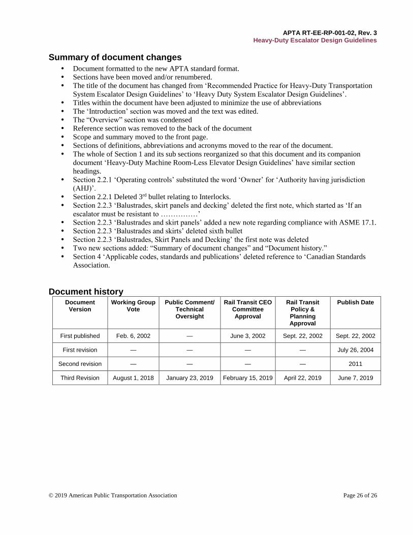
APTA RT-EE-RP-001-02, Rev. 3 Heavy-Duty Escalator Design Guidelines
© 2019 American Public Transportation Association Page 26 of 26
Summary of document changes
Document formatted to the new APTA standard format.
Sections have been moved and/or renumbered.
The title of the document has changed from ‘Recommended Practice for Heavy-Duty Transportation
System Escalator Design Guidelines’ to ‘Heavy Duty System Escalator Design Guidelines’.
Titles within the document have been adjusted to minimize the use of abbreviations
The ‘Introduction’ section was moved and the text was edited.
The “Overview” section was condensed
Reference section was removed to the back of the document
Scope and summary moved to the front page.
Sections of definitions, abbreviations and acronyms moved to the rear of the document.
The whole of Section 1 and its sub sections reorganized so that this document and its companion
document ‘Heavy-Duty Machine Room-Less Elevator Design Guidelines’ have similar section
headings.
Section 2.2.1 ‘Operating controls’ substituted the word ‘Owner’ for ‘Authority having jurisdiction
(AHJ)’.
Section 2.2.1 Deleted 3rd bullet relating to Interlocks.
Section 2.2.3 ‘Balustrades, skirt panels and decking’ deleted the first note, which started as ‘If an
escalator must be resistant to ……………’
Section 2.2.3 ‘Balustrades and skirt panels’ added a new note regarding compliance with ASME 17.1.
Section 2.2.3 ‘Balustrades and skirts’ deleted sixth bullet
Section 2.2.3 ‘Balustrades, Skirt Panels and Decking’ the first note was deleted
Two new sections added: “Summary of document changes” and “Document history.”
Section 4 ‘Applicable codes, standards and publications’ deleted reference to ‘Canadian Standards
Association.
Document history Document
Version Working Group
Vote Public Comment/
Technical Oversight
Rail Transit CEO Committee Approval
Rail Transit Policy & Planning Approval
Publish Date
First published Feb. 6, 2002 — June 3, 2002 Sept. 22, 2002 Sept. 22, 2002
First revision — — — — July 26, 2004
Second revision — — — — 2011
Third Revision August 1, 2018 January 23, 2019 February 15, 2019 April 22, 2019 June 7, 2019