heavy-duty metal sheath element electric portable infrared ... filedeath or serious injury. warning...
TRANSCRIPT

ISSUE DATE 12-12-08 REV. DATE 12-12-08 REV. LEVEL: 01 ECN: GP-5179 OIPM P/N 3420466 PG 1 OF 20
FHK-4 series FHK-2 series FHK-13 series FHK-6 series
FHK-Series
Heavy-duty Metal Sheath Element
Electric Portable Infrared Heaters
A DIVISION
TPI Corporation PHONE: 1-800-251-0382
www.tpicorp.com
IMPORTANT SAFETY
INFORMATION INSIDE
• Serious injury or death possible
• Read, understand, and follow
all safety information and
instructions in this manual
before using or servicing this
product.
• Retain these instructions for
future reference.
REFER TO COMPLETE
INDEX OF
INFORMATION ON
PAGE 2
If you have questions about the
product you have purchased or would
like to leave us feedback please
contact us via our website
www.tpicorp.com
or by calling 1-800-251-0382.

ISSUE DATE 12-12-08 REV. DATE 12-12-08 REV. LEVEL: 01 ECN: GP-5179 OIPM P/N 3420466 PG 2 OF 20
INDEX
General Description & Use Page 3
Specifications Page 4, 5
Installation Planning Page 5, 6, 7
Installation - Wiring Page 8, 9, 10
Operation Page 11, 12
Maintenance Page 12
Element & Reflector Replacement: FHK-2 & FHK-4 Page 13
Element Replacement: FHK-6 & FHK-13 Page 14
Reflector Replacement: FHK-6 & FHK-13 Page 15
Accessories Page 15
Exploded Views & Replacement Parts
FHK-2 Page 16
FHK-4 Page 17
FHK-6 Page 18
FHK-13 Page 19
Limited Warranty Page 20
DANGER indicates an imminently hazardous
situation which, if not avoided, will result in
death or serious injury.
WARNING indicates a potentially hazardous
situation which, if not avoided, could result in death or serious injury.
CAUTION indicates a potentially hazardous
situation which, if not avoided, may result in
minor or moderate injury.
CAUTION used without the safety alert symbol indicates a potentially hazardous situation which,
if not avoided, may result in property damage.
ATTENTION:
The table to the right provides
definitions of the signal words that
can be found throughout this
manual. These signal words are
used to express the severity of the
hazard at hand. The signal words
are generally used in conjunction
with safety symbols that correspond
to the text for that particular hazard.
As you read this manual, refer back
to this table when you are unsure of
the signal word definition.

ISSUE DATE 12-12-08 REV. DATE 12-12-08 REV. LEVEL: 01 ECN: GP-5179 OIPM P/N 3420466 PG 3 OF 20
THANK YOU!!
Thank you very much for selecting Fostoria’s portable electric infrared heating equipment for your
comfort heating needs. These products were engineered with the most reliable components and materials
available and are equipped with features to assure ease of installation and maintenance.
The warmth you will now enjoy when using this heating equipment is created by a heat source; a metal-
sheathed element; that emits infrared energy in the form of heat, like the sun. This is an economical way
to heat because it heats people and objects, not the air, so you don’t need to heat a large area to feel
warm.
CHECKING YOUR SHIPMENT
� Upon receipt of your shipment, check all cartons for visible damage.
� Claims for damaged material or shortages that were not evident upon receipt of shipment must be
reported to carrier and TPI Corporation’s customer service (800-251-0382) immediately.
� Any accessory items ordered for the heater will be shipped in separate cartons.
EXPLOSION HAZARD
FIRE HAZARD
BURN HAZARD
• Serious injury or death may
occur.
• Not for indoor residential use.
• Do not use outdoors in wet
conditions and in unprotected
locations.
• Use for comfort heating only.
• Do not use in locations
containing hazardous or
explosive atmospheres.
• Comply with “REQUIRED
CLEARANCES” table at
right for minimum clearances
to combustible materials.
The Fostoria FHK-series is a line of heavy-duty portable
heaters designed to provide electric infrared heat when
permanently installed heaters are not practical or
economical. They are easily transported to the work site
and connected to disconnect switches or lighting centers.
The units are suited to a wide variety of indoor and
protected outdoor commercial or industrial uses. They
operate cleanly, emitting no fumes or odors.
Applications where combustible materials and/or
personnel will be located near these heaters require the
addition of a ground-fault sensing switch as part of the
electrical circuit. See the INSTALLATION PLANNING
section of this manual for more details. Any installation
of these heaters must also adhere to the minimum
clearance information below.
MODEL
REQUIRED CLEARANCES
TO COMBUSTIBLES
FROM FRONT OF HEATER
FHK-212-1CA 2 Feet
FHK-2 3 feet
FHK-4 3 Feet
FHK-6 4 Feet
FHK-13 7 Feet
GENERAL DESCRIPTION & USE

ISSUE DATE 12-12-08 REV. DATE 12-12-08 REV. LEVEL: 01 ECN: GP-5179 OIPM P/N 3420466 PG 4 OF 20
SPECIFICATIONS
FHK-2 & FHK-4 Series:
� Powder-coated steel base and large carry
handle
� Gold-anodized aluminum housing for good
reflectivity and corrosion resistance
� Housing is of double-wall construction for
reduced surface temperatures
� Features aluminum extrusion and element
support clip for high-vibration areas and rugged
environments
� U-shaped metal-sheath elements are factory-
installed and mounted on a cast aluminum
terminal box
� 120V model (FHK-212-1CA) is equipped with
15ft cordset with NEMA 5-15 molded plug
FHK-6 & FHK-13 Series:
� Heaters are mounted on steel handcarts with 6-
inch wheels, which allow easy transport to the
job site.
� Gold-anodized aluminum housing for good
reflectivity and corrosion resistance
� Housing is of double-wall construction for
reduced surface temperatures
� Features aluminum extrusion and element
support clip for high-vibration areas and rugged
environments
� U-shaped metal-sheath elements are factory-
installed and mounted on a corrosion protected
steel terminal box
� Model FHK-624-1CA is equipped with a 15ft,
type S, 3-wire cable with a #10-3 dryer plug
Amps Amps Dimensions (in.) Heater
Models
Voltage
And Phase 1ph. 3ph.
Number
Of
Elements
Watts Btu’s/Hr.
A B C
FHK-212-1CA 120; 1ph 15.0 n/a 1800 6,142
FHK-220-1A 208; 1ph 9.7 n/a
FHK-224-1A 240; 1ph 8.4 n/a
FHK-227-1A 277; 1ph 7.3 n/a
FHK-248-1A 480; 1ph 4.2 n/a
FHK-257-1A 600; 1ph 3.5 n/a
1 2000 6,824
13-1/2 11-1/2 28-1/2
FHK-420-1A 208; 1ph 21.7 n/a
FHK-424-1A 240; 1ph 18.8 n/a
FHK-427-1A 277; 1ph 16.3 n/a
FHK-448-1A 480; 1ph 9.4 n/a
FHK-457-1A 600; 1ph 7.8 n/a
1 4500 15,355 13-1/2 11-1/2 48-3/4
FHK-620-3A 208; 1 or 3ph 28.9 16.6
FHK-624-3A 240; 1 or 3ph 25.0 14.4
FHK-624-1CA 240; 1ph 25.0 n/a
FHK-627-3A 277; 1ph 21.7 n/a
FHK-648-3A 480; 1 or 3ph 12.5 7.2
3
6000
20,473
FHK-657-3A 600; 1 or 3ph 10.4 6.1
17 19-3/4 37-1/2
FHK-1320-3A 208; 3ph n/a 37.4
FHK-1324-3A 240; 3ph n/a 32.4
FHK-1327-3A 277; 1ph 48.8 n/a
FHK-1348-3A 480; 3ph n/a 16.2
FHK-1357-3A 600; 3ph n/a 13.6
3 13,500 46,064 19 27-1/2 59
Please see illustrations on next page regarding dimensions in table.

ISSUE DATE 12-12-08 REV. DATE 12-12-08 REV. LEVEL: 01 ECN: GP-5179 OIPM P/N 3420466 PG 5 OF 20
SPECIFICATIONS (cont.)
A
C
B
FHK-2 & 4 series
B
C
A
FHK-6 & 13 series
INSTALLATION PLANNING
Fostoria’s metal-sheath infrared heaters are equipped with
heating elements that are manufactured using materials
with exceptional mechanical and thermal performance and
are built with precise process control to provide rugged and
reliable infrared performance in challenging environments.
It is our understanding that these precision characteristics
can change with time, specifically in environments with
high humidity or where mechanical damage can occur,
causing the internal electrical insulation to weaken. Use of
Fostoria’s GF-SK-1 ground fault sensing switch will
monitor this gradual change and interrupt power to the
heaters prior to any arc-fault type failures, thereby
protecting against a possible fire or burn hazard. Any
installation where this is a concern must be protected by
using the GF-SK-1 switch.
FIRE HAZARD
BURN HAZARD
• To prevent arcing type
faults, premature element
failure and potential fire
or burn hazard, use
Fostoria model GF-SK-1
ground fault switch with
these heaters.
• Read and follow all
instructions provided for
proper installation of
heaters and GF-SK-1.

ISSUE DATE 12-12-08 REV. DATE 12-12-08 REV. LEVEL: 01 ECN: GP-5179 OIPM P/N 3420466 PG 6 OF 20
Options for using the GF-SK-1 with Fostoria FHK-Series heaters:
INSTALLATION PLANNING (cont.)
Mounting Option Heater Compatibility
Mounting GF-SK-1 directly
onto heater
FHK-6xx, FHK-13xx (cannot be mounted to FHK-2xx and FHK-4xx)
Wall-mounting the GF-SK-1
(see explanation below)
FHK-2xx, FHK-4xx, FHK-6xx, FHK-13xx
The GF-SK-1 can monitor a single heater as denoted
above but the most cost effective arrangement of the
system is realized when monitoring a circuit of
multiple heaters. The total number of heaters that
can be monitored by one GF-SK-1 is dependant upon
the heater models selected and the supply voltage.
Using the total watts of the selected heaters to be
monitored, the known supply voltage (be certain the
heater voltage rating matches the supply voltage),
and the phase of the supply, the total load or “amps”
can be calculated. The GF-SK-1 is capable of
monitoring a heater circuit of up to 50 amps
maximum. A licensed electrician or design
engineer must do the necessary calculations.
FIRE HAZARD
• Serious injury or death may
occur.
• Heater circuit load
calculations and circuit design
must be done by a licensed
electrician or engineer.
Installer Qualifications
The installation and wiring of Fostoria FHK heaters
must be performed by a licensed electrician.
Installer Responsibility
The National Electric Code (NEC) and local codes
and ordinances together with specifications provided
by Fostoria comprise the information needed for
proper installation. The installer must furnish all
materials that have not been purchased from Fostoria
or its representatives. It is the installer’s responsibility
that the materials and methods of installation result in
a job that is workmanlike and compliant with all
applicable codes.
Over-voltage is a major cause of element
failure with these heaters. Make certain the
power supply voltage is no more than 2%
above the rated voltage of the heater being
utilized.
� The maximum ampacity rating for an infrared
heating circuit is 50A.
� The opening in the terminal box for branch
circuit supply wiring on FHK-2 models is sized
for 1/2-inch trade size cable connectors.
Openings in terminal boxes for supply wiring on
FHK-4, FHK-6 and FHK-13 models are sized for
3/4-inch trade size cable connectors.
� Cable connectors and cables are not provided
with these heaters. (See Specifications on page 4
for exceptions.)
Preparations for Wiring Heaters

ISSUE DATE 12-12-08 REV. DATE 12-12-08 REV. LEVEL: 01 ECN: GP-5179 OIPM P/N 3420466 PG 7 OF 20
AMPS Type SO Cable Size* Heater Model KW VOLTS
3-PH 1-PH 3-PH 1-PH Plug Size 3-PH Plug Size 1-PH
FHK-220-1A 2 208 N/A 9.7 N/A 16/3 N/A NEMA L6-15
FHK-224-1A 2 240 N/A 8.4 N/A 16/3 N/A NEMA L6-16
FHK-227-1A 2 277 N/A 7.3 N/A 16/3 N/A NEMA L7-17
FHK-248-1A 2 480 N/A 4.2 N/A 16/3 N/A NEMA L8-20
FHK-257-1A 2 600 N/A 3.5 N/A 16/3 N/A NEMA L9-20
FHK-420-1A 4.5 208 N/A 21.7 N/A 10/3 N/A 30A/250V/3 Wire
FHK-424-1A 4.5 240 N/A 18.8 N/A 12/3 N/A 20A/250V/3 Wire
FHK-427-1A 4.5 277 N/A 16.3 N/A 12/3 N/A 20A/480V/3 Wire
FHK-448-1A 4.5 480 N/A 9.4 N/A 14/3 N/A 10A/480V/3 Wire
FHK-457-1A 4.5 600 N/A 7.8 N/A 14/3 N/A 10A/600V/3 Wire
FHK-620-3A 6 208 16.6 28.9 12/4 8/3 20A/250V/4 Wire 30A/250V/3 Wire
FHK-624-3A 6 240 14.4 25.0 14/4 10/3 20A/250V/4 Wire 30A/250V/3 Wire
FHK-627-3A 6 277 N/A 21.7 N/A 10/3 N/A 30A/480V/3 Wire
FHK-648-3A 6 480 7.2 12.5 14/4 14/3 20A/480V/4 Wire 20A/480V/3 Wire
FHK-657-3A 6 600 6.1 10.4 14/4 14/3 20A/600V/4 Wire 20A/600v/3 Wire
FHK-1320-3A 13.5 208 37.4 N/A 6/4 N/A 50A/250V/4 Wire N/A
FHK-1324-3A 13.5 240 32.4 N/A 8/4 N/A 50A/250V/4 Wire N/A
FHK-1327-3A 13.5 277 N/A 48.8 N/A 4/3 N/A 50A/480V/3 Wire
FHK-1348-3A 13.5 480 16.2 N/A 12/4 N/A 20A/480V/4 Wire N/A
FHK-1357-3A 13.5 600 13.6 N/A 12/4 N/A 20A/600V/4 Wire N/A
INSTALLATION PLANNING (cont.)
The following tables are provided to assist the licensed electrician in sizing the electric cables and/or plugs
needed for each FHK heater model. Since only models FHK-212-1CA and FHK-624-1CA are equipped with
cables and plugs, these items for all other models will have to be obtained through a local supplier or purchased
separately from Fostoria. (See Table B.)
All supply cables must be copper, rated 90°C and comply with all local codes and the National Electric Code
(NEC).
All recommended wire sizes assume a 50ft. maximum wire length.
Table A
Table B
ELECTRIC CABLES
SIZE/TYPE PART NO. SIZE/TYPE PART NO.
16/3 SO 14/3 SO 14/4 SO 12/3 SO 12/4 SO 10/3 SO
08804300 08804600 08804900 08804500 03164201 08804400
8/3 SO 8/4 SO 6/4 SO 4/3 SO 2/3 SO
08805200 08805100 03164001 08805300 08804700

ISSUE DATE 12-12-08 REV. DATE 12-12-08 REV. LEVEL: 01 ECN: GP-5179 OIPM P/N 3420466 PG 8 OF 20
INSTALLATION – WIRING
For All Heaters
The FHK-series heaters do not have any onboard controls
and therefore all permanently connected heaters must be
used in conjunction with the applicable Fostoria FPC-
series control center or be wired to a listed, properly
rated safety switch for on/off control. Always disconnect
the power at the circuit breaker or disconnect switch
before installing electric power to the heater. If the
breaker or disconnect switch cannot be seen from where
you will be working, lock it in the open position and tag
it to prevent unexpected application of power. Failure to
do so could result in fatal electric shock. Do not
depend on a thermostat or other switch as the sole means
of turning off power to the heater.
To disconnect power to heaters using wall receptacles
and plugs, simply unplug the heater.
“Bonding” is the intentional electrical connection of all
non-current carrying metal parts to the equipment
grounding (green) conductor of the heater and then
terminating this green conductor to the green conductor
of the power supply to form a low-impedance path back
to the power supply so that safety devices (circuit
breakers, fuses) can quickly remove dangerous touch
voltage from these parts when a fault occurs. Always
securely connect the green conductor from the power
supply to the green conductor of the heater.
ELECTRICAL SHOCK
HAZARD
• Serious injury or death
may occur.
• Disconnect heater and lock
out from electrical supply
before installing or
servicing.
• Always securely connect
green wire on heater to
bonding (green) wire from
electrical supply.
Cable
Cable strain relief
Wire nut or other
termination Green to green
Wiring of FHK-2 and FHK-4 Series Heaters
Since all FHK-2 and FHK-4 heaters (except FHK-212-1CA) are received without an electric cable, the
following steps must be taken before attaching the heater to the base:
1. Install a standard or liquid-tight cable connector into the hole in the side of the terminal box. (See page 6
for appropriate cable connector sizes.)
2. Place the properly sized supply cable through the fitting. See page 7 for cable and plug size specifications
or refer to the National Electric Code (NEC).
3. Connect supply cable leads to the element lead wires in the terminal box with wire nuts or other safe
mechanical means. Black and white cable leads can be connected to either element lead wire. Connect
green lead from supply cable to green (bonding) lead in the terminal box. (See illustration shown above.)
Continued on next page

ISSUE DATE 12-12-08 REV. DATE 12-12-08 REV. LEVEL: 01 ECN: GP-5179 OIPM P/N 3420466 PG 9 OF 20
4. Position the rubber gasket (item 18) and the
base (item 21) on the bottom of the terminal
box (item 7), aligning the slotted holes.
Fasten the base and terminal box together
with the screws and nuts (items 16 & 17)
provided. (See page 14 (FHK-2) or 15 (FHK-
4) for item number list.)
5. Screw handle (item 22) onto the 3/8” bolt on
the back of the housing.
6. Connect heater to a suitable electric circuit.
Note: Handle, gasket, bolts, and nuts are in
hardware package 3917900.
INSTALLATION – WIRING (cont.)
22
Base and handle
Assembly view
7
21
17
18
16
ISSUE DATE 12-12-08 REV. DATE 12-12-08 REV. LEVEL: 01 ECN: GP-5179 OIPM P/N 3420466 PG 10 OF 20
INSTALLATION – WIRING (cont.)
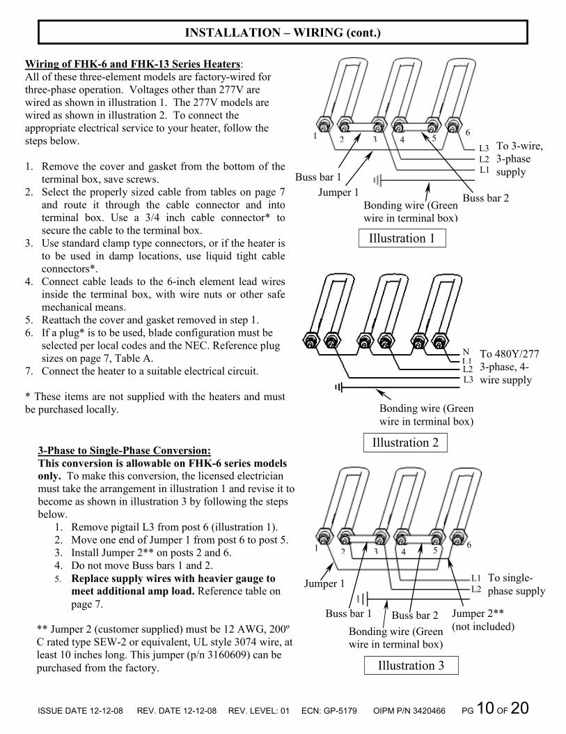
Wiring of FHK-6 and FHK-13 Series Heaters:
All of these three-element models are factory-wired for
three-phase operation. Voltages other than 277V are
wired as shown in illustration 1. The 277V models are
wired as shown in illustration 2. To connect the
appropriate electrical service to your heater, follow the
steps below.
1. Remove the cover and gasket from the bottom of the
terminal box, save screws.
2. Select the properly sized cable from tables on page 7
and route it through the cable connector and into
terminal box. Use a 3/4 inch cable connector* to
secure the cable to the terminal box.
3. Use standard clamp type connectors, or if the heater is
to be used in damp locations, use liquid tight cable
connectors*.
4. Connect cable leads to the 6-inch element lead wires
inside the terminal box, with wire nuts or other safe
mechanical means.
5. Reattach the cover and gasket removed in step 1.
6. If a plug* is to be used, blade configuration must be
selected per local codes and the NEC. Reference plug
sizes on page 7, Table A.
7. Connect the heater to a suitable electrical circuit.
* These items are not supplied with the heaters and must
be purchased locally.
** Jumper 2 (customer supplied) must be 12 AWG, 200º
C rated type SEW-2 or equivalent, UL style 3074 wire, at
least 10 inches long. This jumper (p/n 3160609) can be
purchased from the factory.
3-Phase to Single-Phase Conversion:
This conversion is allowable on FHK-6 series models
only. To make this conversion, the licensed electrician
must take the arrangement in illustration 1 and revise it to
become as shown in illustration 3 by following the steps
below.
1. Remove pigtail L3 from post 6 (illustration 1).
2. Move one end of Jumper 1 from post 6 to post 5.
3. Install Jumper 2** on posts 2 and 6.
4. Do not move Buss bars 1 and 2.
5. Replace supply wires with heavier gauge to
meet additional amp load. Reference table on
page 7.
Bonding wire (Green
wire in terminal box)
Illustration 1
Jumper 1
Buss bar 1
Buss bar 2
To 3-wire,
3-phase
supply
L3
L2
L1
Bonding wire (Green
wire in terminal box)
To 480Y/277
3-phase, 4-
wire supply
Illustration 2
N L1 L2 L3
1 2 3 4 5 6
Illustration 3
Bonding wire (Green
wire in terminal box)
To single-
phase supply
Buss bar 1
Jumper 1
Buss bar 2 Jumper 2**
(not included)
L1
L2
1 2 3 4 5 6
ISSUE DATE 12-12-08 REV. DATE 12-12-08 REV. LEVEL: 01 ECN: GP-5179 OIPM P/N 3420466 PG 11 OF 20
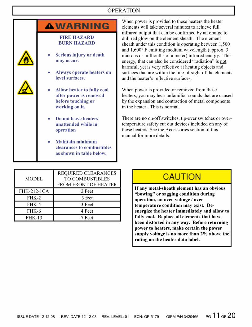
OPERATION
When power is provided to these heaters the heater
elements will take several minutes to achieve full
infrared output that can be confirmed by an orange to
dull red glow on the element sheath. The element
sheath under this condition is operating between 1,500
and 1,600° F emitting medium wavelength (approx. 3
microns or millionths of a meter) infrared energy. This
energy, that can also be considered “radiation” is not
harmful, yet is very effective at heating objects and
surfaces that are within the line-of-sight of the elements
and the heater’s reflective surfaces.
When power is provided or removed from these
heaters, you may hear unfamiliar sounds that are caused
by the expansion and contraction of metal components
in the heater. This is normal.
There are no on/off switches, tip-over switches or over-
temperature safety cut out devices included on any of
these heaters. See the Accessories section of this
manual for more details.
FIRE HAZARD
BURN HAZARD
• Serious injury or death
may occur.
• Always operate heaters on
level surfaces.
• Allow heater to fully cool
after power is removed
before touching or
working on it.
• Do not leave heaters
unattended while in
operation
• Maintain minimum
clearances to combustibles
as shown in table below.
MODEL
REQUIRED CLEARANCES
TO COMBUSTIBLES
FROM FRONT OF HEATER
FHK-212-1CA 2 Feet
FHK-2 3 feet
FHK-4 3 Feet
FHK-6 4 Feet
FHK-13 7 Feet
If any metal-sheath element has an obvious
“bowing” or sagging condition during
operation, an over-voltage / over-
temperature condition may exist. De-
energize the heater immediately and allow to
fully cool. Replace all elements that have
been distorted in any way. Before returning
power to heaters, make certain the power
supply voltage is no more than 2% above the
rating on the heater data label.

ISSUE DATE 12-12-08 REV. DATE 12-12-08 REV. LEVEL: 01 ECN: GP-5179 OIPM P/N 3420466 PG 12 OF 20
Ground-Fault Monitoring and Operation:
As explained in the “installation planning” section of
this manual, most, if not all, applications using metal-
sheath heaters will require the use of the GF-SK-1
ground-fault sensor switch. Refer to the instructions
provided with this switch for proper installation.
If, during heater operation, the GF-SK-1 “trips” and
interrupts power to your heater or heater circuit, then
one or more of the metal-sheath elements in the
heater or heater circuit being monitored has a reduced
insulation resistance value that may be due to an
element that is about to fail. Have a licensed
electrician follow the warnings and instructions in the
“operation” section of the GF-SK-1 manual.
OPERATION (cont.)
FIRE HAZARD
BURN HAZARD
• To prevent arcing type
faults, premature element
failure and potential fire
or burn hazard, use
Fostoria model GF-SK-1
ground fault switch with
these heaters.
• Read and follow all
instructions provided for
proper installation of
heaters and GF-SK-1.
MAINTENANCE
Pre-Season Maintenance and Annual Inspection To ensure your safety and years of trouble-free operation from the heaters, periodic service and inspections
must be done by a trained maintenance person or licensed electrician.
To obtain maximum performance from your heater(s) each year, we recommend the following be
performed at the start of the heating season:
1. Clean housing reflector surfaces with a damp cloth.
2. Blow or dust off the elements and inner reflectors.
3. Repair or replace damaged power cables.
4. DO NOT hose-down these heaters.
Storage
When storing the heaters for long periods they should be covered to avoid accumulation of dust and other
contaminants. Keep them in dry areas away from dripping or standing water and heavy humidity.
• Do not store in a damp location.

ISSUE DATE 12-12-08 REV. DATE 12-12-08 REV. LEVEL: 01 ECN: GP-5179 OIPM P/N 3420466 PG 13 OF 20
ELECTRICAL SHOCK HAZARD
• Serious injury or death may occur.
• Disconnect heaters from electrical
supply before replacing parts.
Use only Fostoria replacement elements of the
same wattage, voltage and part number as the
original element. Reference tables on
replacement parts pages later in this manual.
Always install new reflector included with each
replacement element.
ELEMENT & REFLECTOR REPLACEMENT: FHK-2 & FHK-4
1. DISCONNECT POWER FROM THE ELECTRICAL
SUPPLY CABLE OF THE PORTABLE HEATER
BEING REPAIRED.
2. Position heater on workbench with reflector opening
pointing UP.
3. Remove wire guard by taking out the (5) screws shown
in Illustration 4 with a 5/16” nut driver, save hardware.
4. Remove element support clip (2 on FHK-4 models),
save clip(s).
5. Remove base and gasket from terminal box on heater;
save base, gasket and hardware.
6. Disconnect the 2 wires from heating element by
loosening the 3/8” hex nuts at the bottom of the rod.
7. Remove old element by removing the large hex nuts,
metal washers and gaskets, discard all.
8. Slide old reflector out of the extrusion and discard.
9. Peel protective film from new reflector, and then place
it in the extrusion. Make sure reflector is secured in
slots in extrusion.
10. Install new element in terminal box, using hardware
included. See Illustration 5.
11. Reinstall element support clip(s), removed in Step 4,
into extrusion.
12. Connect the two wires to the element as shown in
Illustration 5. Make sure that bare metal wire terminals
from different posts do not come in contact with each
other.
13. Reattach base and gasket to terminal box with
hardware removed in Step 5.
14. Reattach wire guard to housing with screws removed
in Step 3.
15. Heater is now ready for normal operation.
Screw
Screw Base
Illustration 4
Hex nut
Terminal box Gasket
Wire guard
Screw
Metal-sheath
element
Hex nut
Hex nut
Large hex nut
Metal washer
Gasket
Washer Wire & terminal
Illustration 5
Illustration 6
Support clip
Reflector
Extrusion
Slot

ISSUE DATE 12-12-08 REV. DATE 12-12-08 REV. LEVEL: 01 ECN: GP-5179 OIPM P/N 3420466 PG 14 OF 20
ELEMENT REPLACEMENT: FHK-6 & FHK-13
ELECTRICAL SHOCK HAZARD
• Serious injury or death may
occur.
• Disconnect heaters from
electrical supply before
replacing parts.
Use only Fostoria replacement elements of
the same wattage, voltage and part number
as the original element. Reference tables on
replacement parts pages later in this
manual.
Always install new reflector included with
each replacement element.
1. DISCONNECT POWER FROM THE ELECTRICAL
SUPPLY CABLE OF THE PORTABLE HEATER
BEING REPAIRED.
2. Position heater with reflector opening pointing UP.
3. Remove the wire guard from the heater to access the
fasteners that attach the terminal box. Remove and
save the (12) screws shown in Illustration 7 with a
5/16” nut driver.
4. Remove and save the (4) screws that attach the
terminal box to the heater, with a 1/4” nut driver. See
Illustration 8.
5. Grasp terminal box assembly and firmly pull in the
direction shown in Illustration 9. The elements have
been fed through some support clips inside the heater
housing. These clips will cause some drag or
resistance to removal. There will be some unpleasant
noise as the elements slide through the clips.
6. Remove cover and gasket from terminal box; save
them and all screws.
7. Disconnect the wires from only the heating element to
be replaced by loosening the 3/8” hex nuts at the
bottom of the element similar to Illustration 5.
8. Remove old element by removing the large hex nuts,
metal washers and gaskets, discard all.
9. Install new element in terminal box, using hardware
included. See Illustration 5.
10. Reconnect the wires to the element as they were
before removal. Make sure that bare metal wire
terminals from different posts do not come in contact
with each other.
11. Reattach base, gasket and screws to terminal box.
12. Before reinstalling the heating elements, the old
reflector should be replaced with the new one received
with the new heating element. See next page for
Reflector Replacement.
13. After completing all steps in Reflector Replacement,
place the heating element assembly back into the
housing and secure with screws removed in Step 4.
14. Reattach wire guard with screws removed in Step 3.
15. Heater is now ready for normal operation.
Illustration 7
Screw
Illustration 8 (4) Screws
Illustration 9
Support clip locations
ISSUE DATE 12-12-08 REV. DATE 12-12-08 REV. LEVEL: 01 ECN: GP-5179 OIPM P/N 3420466 PG 15 OF 20
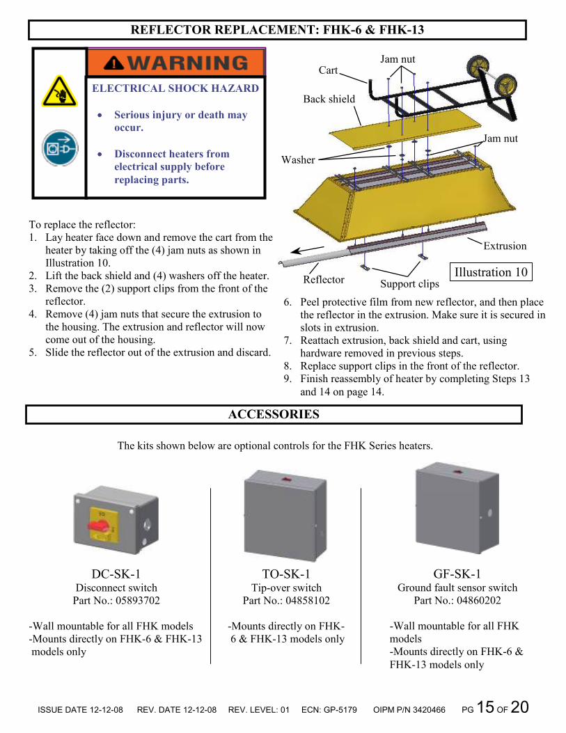
REFLECTOR REPLACEMENT: FHK-6 & FHK-13
ELECTRICAL SHOCK HAZARD
• Serious injury or death may
occur.
• Disconnect heaters from
electrical supply before
replacing parts.
To replace the reflector:
1. Lay heater face down and remove the cart from the
heater by taking off the (4) jam nuts as shown in
Illustration 10.
2. Lift the back shield and (4) washers off the heater.
3. Remove the (2) support clips from the front of the
reflector.
4. Remove (4) jam nuts that secure the extrusion to
the housing. The extrusion and reflector will now
come out of the housing.
5. Slide the reflector out of the extrusion and discard.
6. Peel protective film from new reflector, and then place
the reflector in the extrusion. Make sure it is secured in
slots in extrusion.
7. Reattach extrusion, back shield and cart, using
hardware removed in previous steps.
8. Replace support clips in the front of the reflector.
9. Finish reassembly of heater by completing Steps 13
and 14 on page 14.
Illustration 10
Jam nut Cart
Back shield
Washer
Jam nut
Reflector
Extrusion
Support clips
ACCESSORIES
The kits shown below are optional controls for the FHK Series heaters.
DC-SK-1 Disconnect switch
Part No.: 05893702
-Wall mountable for all FHK models
-Mounts directly on FHK-6 & FHK-13
models only
TO-SK-1 Tip-over switch
Part No.: 04858102
-Mounts directly on FHK-
6 & FHK-13 models only
GF-SK-1 Ground fault sensor switch
Part No.: 04860202
-Wall mountable for all FHK
models
-Mounts directly on FHK-6 &
FHK-13 models only

ISSUE DATE 12-12-08 REV. DATE 12-12-08 REV. LEVEL: 01 ECN: GP-5179 OIPM P/N 3420466 PG 16 OF 20
FHK-2 EXPLODED VIEW AND REPLACEMENT PARTS LIST
2
19 3 6 10 9
14
13
23
17 7 12
18 21 16
4
1
15 20 11
5
8
25 24
ITEM NO. 1 2 3 4 5 6 7 8 9 10 11 12 13 14 15 16 17 18 19 20 21 22 23 24 25
DESCRIPTION
Side baffle Back shield Mounting bracket Mounting brace Pop rivet Extrusion Terminal box Reflector Element support Screw 3/8-16 x 1/2 Nut 3/8-16 Screw 10-32 x 3/8 Wire guard Screw 10-32 x 3/4 Nut self-retaining 10-32 Screw 8-32 x 1/2 Nut 8-32 Gasket Screw 3/8-16 x 1 Washer fender 3/8 Base Handle Metal-sheath element Cable connector 1/2” * 14-3 Cordset *
PART NUMBER
8022707 8022607 8023000 8023100 3482200 8041700 8040501 8048900 8024100 3474300 3429100 3475000 8022329 3424956 3403900 3427456 3405156 8040700 3493900 3478600 8042921 8041800
See Table 1 7714114 3175600
QTY. 2 1 1 1 18 1 1 1 1 2 3 1 1 5 5 4 4 1 1 1 1 1 1 1 1
Table 1
MODEL VOLTS
METAL-
SHEATH
ELEMENT
PART NUMBER
FHK-212-1CA 120 04458702
FHK-220-1A 208 04458302
FHK-224-1A 240 04457902
FHK-227-1A 277 04458402
FHK-248-1A 480 04458002
FHK-257-1A 600 04458802

ISSUE DATE 12-12-08 REV. DATE 12-12-08 REV. LEVEL: 01 ECN: GP-5179 OIPM P/N 3420466 PG 17 OF 20
FHK-4 EXPLODED VIEW AND REPLACEMENT PARTS LIST
11 5
20
2
19 3 6 15 10 8
9
14
13
23
17
7
12
18 21 16
4
1
ITEM NO. 1 2 3 4 5 6 7 8 9 10 11 12 13 14 15 16 17 18 19 20 21 22 23
DESCRIPTION
Side baffle Back shield Mounting bracket Mounting brace Pop rivet Extrusion Terminal box Reflector Element support Screw 3/8-16 x 1/2 Jam nut 3/8-16 Screw 10-32 x 3/8 Wireguard Screw 10-32 x 3/4 Nut self-retaining 10-32 Screw 8-32 x 1/2 Hex nut 8-32 Gasket Screw 3/8-16 x 1 Fender washer 3/8” Base Handle Metal-sheath element
PART NUMBER
8022907 8022807 8023000 8023100 3482200 8042400 8040502 8049000 8024100 3474300 3429100 3475000 8022429 3424956 3403900 3427456 3405156 8040700 3493900 3478600 8042921 8041800
See Table 2
QTY. 2 1 2 1 26 1 1 1 2 3 4 1 1 7 7 4 4 1 1 1 1 1 1
Table 2
MODEL VOLTS
METAL-
SHEATH
ELEMENT
PART NUMBER
FHK-420-1A 208 04458502
FHK-424-1A 240 04458102
FHK-427-1A 277 04458602
FHK-448-1A 480 04461702
FHK-457-1A 600 04458902

ISSUE DATE 12-12-08 REV. DATE 12-12-08 REV. LEVEL: 01 ECN: GP-5179 OIPM P/N 3420466 PG 18 OF 20
FHK-6 EXPLODED VIEW AND REPLACEMENT PARTS LIST
26
24
23
25 27
16
4
13
19
12
3
1410
1911
15
7
6 5 2
8
17
818
22
20
21
1
ITEM. NO. 1 2 3 4 5 6 7 8 9 10 11 12 13 14 15 16 17 18 19 20 21 22 23 24 25 26 27
DESCRIPTION
Housing Assembly Extrusion Terminal box Terminal box cover Reflector Metal sheath element support Screw 3/8-16 x 1/2 Jam nut 3/8-16 Screw 8-18 x 1/2 Hex head screw 8-15 x 1/2 Hex head screw 10-32 x 3/8 Gasket Lamp guard Back shield Screw 3/8-16 x 1 Screw 10-32 x 5/8 Self retaining nut 10-32 Fender washer 3/8” Metal-sheath element Cable 10-3 type S x 15’ long * Plug 3-pole 3-wire 30-50 amps * 3/4” cable connector * Tubing plug Cart weld assembly Cart axle Wheel Push nut 1/2” diameter
PART NUMBER
8827999 8041700 8040802 8040900 8048900 8024100 3474300 3429100 3444456 3470800 3475000 8041000 8020829 8020707 3493900 3424956 3403900 3478600
See Table 3 3163601 3180000 7714124 2415100 3924402 8523632 8043600 8045700
QTY. 1 3 1 1 3 3 2 10 4 4 1 1 1 1 4 8 8 4 3 1 1 1 2 1 1 2 2
Table 3
MODEL VOLTS
METAL-
SHEATH
ELEMENT
PART NUMBER
FHK-620-3A 208 04458302
FHK-624-3A 240 04457902
FHK-624-1CA 240 04457902
FHK-627-3A 277 04458402
FHK-648-3A 480 04458002
FHK-657-3A 600 04458802

ISSUE DATE 12-12-08 REV. DATE 12-12-08 REV. LEVEL: 01 ECN: GP-5179 OIPM P/N 3420466 PG 19 OF 20
FHK-13 EXPLODED VIEW AND REPLACEMENT PARTS LIST
13
16
4
24
3
12
10
9
11
14
6
7
15
5
2
8
18
8
17
21
19
23
20 22
1
ITEM. NO. 1 2 3 4 5 6 7 8 9 10 11 12 13 14 15 16 17 18 19 20 21 22 23 24
DESCRIPTION
Housing Assembly Extrusion Terminal box Terminal box cover Reflector Metal sheath element support Screw 3/8-16 x 1/2 Jam nut 3/8-16 Screw 8-18 x 1/2 Hex head screw 8-15 x 1/2 Hex head screw 10-32 x 3/8 Gasket Lamp guard Back shield Screw 3/8-16 x 1 Screw 10-32 x 5/8 Self retaining nut 10-32 Fender washer 3/8” Cart weld assembly Cart axle Wheel Push nut 1/2” diameter Tubing plug Metal-sheath element
PART NUMBER
8829599 8042400 8040802 8040900 8049000 8024100 3474300 3429100 3444456 3470800 3475000 8041000 8021929 8021707 3493900 3424956 3403900 3478600 3924402 8523632 8043600 8045700 2415100
See Table 4
QTY. 1 3 1 1 3 6 8 16 4 4 1 1 1 1 4 12 12 4 1 1 2 2 2 3
Table 4
MODEL VOLTS
METAL-
SHEATH
ELEMENT
PART NUMBER
FHK-1320-3A 208 04458502
FHK-1324-3A 240 04458102
FHK-1327-3A 277 04458602
FHK-1348-3A 480 04461702
FHK-1357-3A 600 04458902

ISSUE DATE 12-12-08 REV. DATE 12-12-08 REV. LEVEL: 01 ECN: GP-5179 OIPM P/N 3420466 PG 20 OF 20
LIMITED WARRANTY
TPI Corporation – P.O. Box 4973 – Johnson City, TN 37602 – 1-800-251-0382 The warranty herein set forth is in lieu of all other warranties expressed or implied. TPI Corporation of Johnson City, TN 37602, warrants its products to the owner against defects in material and workmanship for a twelve (12) month period under normal use and service following date of manufacture or installation when proof of such is provided to seller. This Warranty requires that the owner, or his agent, install the equipment in accordance with the National Electrical Code, any other applicable heating or electrical codes and the manufacturer’s installation instructions. It further requires that he perform reasonable and necessary maintenance on the unit. The company is not liable for abuse or misuse of product as may be finally determined by the company. The obligation of TPI Corporation under the terms of this warranty, shall be to supply a new part, repair of defective part, or a refund, at the company’s option with no cost to owner for the new or repaired part. Such parts are to be returned to the factory, or such other location as the company may designate. This warranty does not obligate TPI Corporation to bear the cost of labor in replacing any assembly, unit or component part thereof, nor does the company assume any liability for secondary charges, expenses for installing or removal, or any other consequential losses. The company’s maximum liability shall not in any case exceed the list price for the product claimed to be defective. The warranty shall not apply to any product or parts of products that have been repaired or altered outside of Seller’s factory in any manner. Warranty is void on products that have been determined to have been subjected to misuse, negligence or accident or which have been used in a manner contrary to Seller’s instructions.

Issue Date: 6-05-07 Rev. Date: 11-06-09 Rev. Level: 03 EC0: 1-6137 OIPM P/N 8324 Page 1 of 4
REQUIRED CLEARANCE WARNING: HAZARD OF FIRE: Minimum spacing from front of heater to combustible materials is: 4 feet for models: FHK-622-1A, 638-3A 7 feet for models: FHK-1322-1A, 1338-3A
WARNING! DO NOT ATTEMPT TO INSTALL, OPERATE, OR SERVICE THIS PRODUCT BEFORE READING ALL INSTRUCTIONS CAREFULLY. FAILURE TO COMPLY WITH THESE INSTRUCTIONS COULD RESULT IN FIRE, PERSONAL INJURY AND/OR PROPERTY DAMAGE! RETAIN INSTRUCTIONS FOR FUTURE REFERENCE.
Fostoria portable heavy-duty radiant heaters are designed to provide electric infrared heat when permanent type heating is not practical or economical. They can be wheeled to the job and connected to disconnect switches or lighting centers. All units are clean in operation, and are weather resistant. NOTE: The metal sheath heating element must be shielded from wind for maximum efficiency. All models are supported on a steel handcart with two 6 inch semi-pneumatic wheels. These models have reflectors that can be adjusted to horizontal or vertical position for best heat pattern. Protective wire guards are standard.
DESCRIPTION
6 KW UNITS Power requirements: FHK-622-1A………..…220V (1PH: 27.3 Amps) FHK-638-3A……….….380V (3PH: 9.1 Amps) Heat output..........................….….....………………….……....6KW
Overall dimensions:…..…….37-3/4” H x 19-7/8” W x 16” D Housing………………….…..0.040 gold anodized aluminum Reflector…………………….………….0.032 BOS aluminum
13 KW UNITS Power requirement: FHK-1322-1A……….220V (1PH: 61.4 Amps) FHK-1338-3A……….380V (3PH: 20.5 Amps) Heat output..............................…………………………….13.5KW Overall dimensions:……...……….58” H x 27-1/2” W x 19” D Housing…………….………..0.040 gold anodized aluminum Reflector…………………….………….0.032 BOS aluminum
SPECIFICATIONS
Read all instructions before using this heater. 1. Make certain that the power source conforms to the electrical
requirements of the heater. Disconnect power before installing or servicing. If the power disconnect is out of sight, lock it in the open position and tag it to prevent unexpected application of power. Failure to do so could result in fatal electric shock.
WARNING: DO NOT DEPEND UPON A THERMOSTAT OR OTHER SWITCH AS THE SOLE MEANS OF DISCONNECTING POWER WHEN INSTALLING OR SERVICING THE HEATER. ALWAYS DISCONNECT POWER AT THE MAIN CIRCUIT BREAKER AS DESCRIBED ABOVE. FAILURE TO DO SO COULD RESULT IN FATAL ELECTRIC SHOCK. 2. This heater is intended ONLY for installation in accordance with the
National Electric Code (NEC), all applicable local codes and ordinances, and all sections of this manual. Any variance voids the warranty and may create unsafe conditions. All wiring should be done by a qualified electrician, using copper wire only.
3. Special attention must be given to any grounding information
pertaining to this heater. To prevent the risk of electrocution, the heater must be securely and adequately grounded. This should be accomplished by connecting a grounded conductor between the service panel and the green grounding screw provided on the heater. To ensure a proper ground, the grounding means must be tested by a qualified electrician
4. Do not insert fingers or foreign objects into the heater. Do not block
or tamper with the heater in any manner while it is in operation. Do not touch heater while in operation or just after it has been turned off, as some parts may be hot enough to cause injury.
IMPORTANT SAFETY INFORMATION
ELECTRIC PORTABLE HEATER
MODEL & PART NO.’S: FHK-622-1A (04859502) FHK-638-3A (04859402)
FHK-1322-1A (04859302) FHK-1338-3A (04859202)
OPERATION – INSTALLATION – PARTS MANUAL

Issue Date: 6-05-07 Rev. Date: 11-06-09 Rev. Level: 03 EC0: 1-6137 OIPM P/N 8324 Page 2 of 4
5. Do not attach ductwork to this heater or attempt to use it as a make-up air heater. Such use voids the warranty and may create unsafe conditions.
6. This heater is intended for general heating applications
ONLY. IT MUST NOT BE USED IN POTENTIALLY DANGEROUS LOCATIONS SUCH AS FLAMMABLE, EXPLOSIVE, CHEMICAL-LADEN, OR WET ATMOSPHERES.
7. In cases in which property damage may result from
malfunction of the heater, a backup system or a temperature sensitive alarm should be used.
8. CAUTION: Check branch voltage. Heaters should be
operated at voltages no higher than the heating elements and the heater are designed for. (Lower voltages, however, pose no problem other than a loss of wattage).
SAFETY INFORMATION (CONT.)
WIRING INSTRUCTIONS CAUTION: To protect against potential fire hazard, these heaters must be protected by one of the following fast acting fuses:
Gould-Shawmut Buss ATM A4J KTS-R KTN-R A2K A6K KTK JKS
The fuse must be as close to the amps shown on the nameplate as possible. 1. Remove the 4 machine screws holding the cover in place on
the bottom of the terminal box. 2. Select the proper cable size per Table A (page 3). Install a
3/4 inch cable connector (customer supplied). 3. Use standard clamp type connectors, or if the heater is to be
used outdoors or in damp locations, use liquid tight cable connectors. (Customer supplied)
4. Connect cable to the 6-inch lead wires inside the terminal box, with wire nuts or other safe mechanical means.
5. For proper cable size, see Table A on page 3 6. Connect the heater to a suitable electrical circuit.
9. If metal sheath (metal rod element) has an obvious "bowing", an over-voltage/over-temperature condition exists. In case of a bowing condition, de-energize the heater immediately and contact the factory.
10. Heaters are not intended and are not safe for process heating
applications. 11. This heater is not equipped with a tip-over switch or an over-
temperature safety cutoff and therefore should not be used in close proximity to flammable materials.
12. Do not store in a damp location. WARNING: FAILURE TO FOLLOW ABOVE SAFETY INSTRUCTIONS COULD RESULT IN FATAL SHOCK HAZARDS!
SAVE THESE INSTRUCTIONS!
NOTE: It is normal for any high intensity heater to create some expansion or contraction noises during heat-up and cool-down cycles. These noises are nothing to be concerned about. Heaters are energized by placing the plug (customer supplied) into a grounded, matching receptacle, or wiring to an approved safety switch.
OPERATING INSTRUCTIONS
1 2
3 4
GROUND (Green Wire from Terminal Box)
5 6
1 2
3 4
L1 L2
GROUND (Green Wire from Terminal Box)
5 6
Figure 2 1 PHASE
Figure 1 3-PHASE
L1 L2 L3

Issue Date: 6-05-07 Rev. Date: 11-06-09 Rev. Level: 03 EC0: 1-6137 OIPM P/N 8324 Page 3 of 4
WARNING: BE SURE TO TURN OFF POWER TO THE HEATER, OR REMOVE FUSES, TO ENSURE ANOTHER PERSON IN A REMOTE LOCATION CANNOT ENERGIZE THE HEATER WHILE REPLACING ELEMENTS OR PERFORMING ANY OTHER MAINTENANCE OPERATIONS. 1. Be sure heater is disconnected from power supply. Remove
old element. 2. To replace an element, insert the U-shaped element through
slots in the reflector and through holes in the terminal box. 3. Place gasket over element threads inside terminal box.
Then replace metal washer and hex nut, and tighten. 4. Replace stakon to tab on the element, to connect the power
supply. Replace rod support. 5. Use only Fostoria replacement elements of the same
wattage/voltage and part number of the original element. (See Table A)
NOTE: A replacement inner reflector (reference no. 5) is included with every U-rod element replacement order. Install the new inner reflector when replacing elements.
Heater Model KW VOLTS PH AMPS Type S Cable Size*
Leadwire Item #26
Ground wire Item #27
Buss Bar Item #28
Element Item #24
FHK-622-1A 6 220 1 27.3 10/3 3160301 3160704 2415001 04860702 FHK-638-3A 6 380 3 9.1 12/4 3160633 3160704 2415000 04860802
FHK-1322-1A 13.5 220 1 61.4 6/3 6160301 3160704 2415001 04860902 FHK-1338-3A 13.5 380 3 20.5 12/4 6160633 3160704 2415000 04861002
* 50 ft. Maximum Cable Length
ELEMENT REPLACEMENT
Blow dust off the elements and inner reflectors prior to heating season, and more often in dusty environments. Repair or replace damaged or worn cord sets (cables) immediately.
MAINTENANCE
Table A

Issue Date: 6-05-07 Rev. Date: 11-06-09 Rev. Level: 03 EC0: 1-6137 OIPM P/N 8324 Page 4 of 4
14
8
8 18
7,15
10 3 12 4
9
11
17 1 5 2 24 6 23
19
20, 22
21
13
16 25 25
REF. NO. DESCRIPTION PART NO. QTY. REF.
NO. DESCRIPTION PART NO. QTY.
1 Housing assembly 8827999 1 1 Housing assembly 8829599 1
2 Extrusion 8041700 3 2 Extrusion 8042400 3 3 Terminal box 8040802 1 3 Terminal box 8040802 1 4 Terminal box cover 8040900 1 4 Terminal box cover 8040900 1 5 Reflector 8048900 3 5 Reflector 8049000 3 6 Metal rod support 8024100 3 6 Metal rod support 8024100 6 7 3/8-16 x 1/2 hex hd screw 3474300 2 7 3/8-16 x 1/2 hex hd screw 3474300 8 8 3/8-16 jam nut 3429100 10 8 3/8-16 jam nut 3429100 16 9 8-32 x 1/2 hex hd washer screw 3444456 4 9 8-32 x 1/2 hex hd washer screw 3444456 4 10 8 x 1/2 hex hd screw 3470800 4 10 8 x 1/2 hex hd screw 3470800 4 11 10-32 x 3/8 hex hd screw 3475000 1 11 10-32 x 3/8 hex hd screw 3475000 1 12 Gasket 8041000 1 12 Gasket 8041000 1 13 Lampguard 8020829 1 13 Lampguard 8021929 1 14 Back shield 8020707 1 14 Back shield 8021707 1 15 3/8-16 x 1 hex hd screw 3493900 4 15 3/8-16 x 1 hex hd screw 3493900 4 16 10-32 x 5/8 hex hd screw 3424956 8 16 10-32 x 5/8 hex hd screw 3424956 12 17 10-32 self retaining nut 3403900 8 17 10-32 self retaining nut 3403900 12 18 3/8 fender washer 3478600 4 18 3/8 fender washer 3478600 4 19 Cart weld assembly 3924402 1 19 Cart weld assembly 3924402 1 20 Cart axle 8523632 1 20 Cart axle 8523632 1 21 Wheel 8043600 2 21 Wheel 8043600 2 22 Push nut 1/2 dia. 8045700 2 22 Push nut 1/2 dia. 8045700 2 23 Handle grip 8043700 2 23 Handle grip 8043700 2 24 U-shaped metal rod element See Table A 3 24 U-shaped metal rod element See Table A 3 25 10 flat washer 3400832 24 25 10 flat washer 3400832 24 26 Wire assy. BLK See Table A 2 26 Wire assy. BLK See Table A 2 27 Wire assy. GRN See Table A 1 27 Wire assy. GRN See Table A 1 28 Buss bar See Table A 2 28 Buss bar See Table A 2
The obligation of Fostoria Industries, Inc. under the terms of this warranty, shall be to supply a new part, repair of defective part, or a refund, at the company’s option with no cost to owner for the new or repaired part. Such parts are to be returned to the factory, or such other location as the company may designate. This warranty does not obligate Fostoria Industries, Inc. to bear the cost of labor in replacing any assembly, unit or component part thereof, nor does the company assume any liability for secondary charges, expenses for installing or removal, or any other consequential losses. The company’s maximum liability shall not in any case exceed the list price for the product claimed to be defective. The warranty shall not apply to any product or parts of products that have been repaired or altered outside of Seller’s factory in any manner. Warranty is void on products that have been determined to have been subjected to misuse, negligence or accident or which have been used in a manner contrary to Seller’s instructions.
The warranty herein set forth is in lieu of all other warranties expressed or implied. Fostoria Industries, Inc. of Fostoria, Ohio 44830, warrants its products to the owner against defects in material and workmanship for a twelve (12) month period under normal use and service following date of manufacture or installation when proof of such is provided to seller. This Warranty requires that the owner, or his agent, install the equipment in accordance with the National Electrical Code, any other applicable heating or electrical codes and the manufacturer’s installation instructions. It further requires that he perform reasonable and necessary maintenance on the unit. The company is not liable for abuse or misuse of product as may be finally determined by the company.
FOSTORIA INDUSTRIES, INC., 1200 N. Main St. - Fostoria, Ohio 44830 - (419) 435-9201 WARRANTY
REPLACEMENT PARTS LIST and EXPLODED VIEW
FHK-6 FHK-13