heavy duty scraper (-xc4) coil scraper (-xc35) etc. are
TRANSCRIPT
New series addedNew series added
¡Standard type, Double rod: Series CP96-W
¡Non-rotating rod type, Single rod: Series CP96K
Double rod: Series CP96K-W
Made to Order addedMade to Order added¡Heat resistant cylinder (-XB6)
¡Heavy duty scraper (-XC4)
¡Coil scraper (-XC35) etc. are added.
NewNew
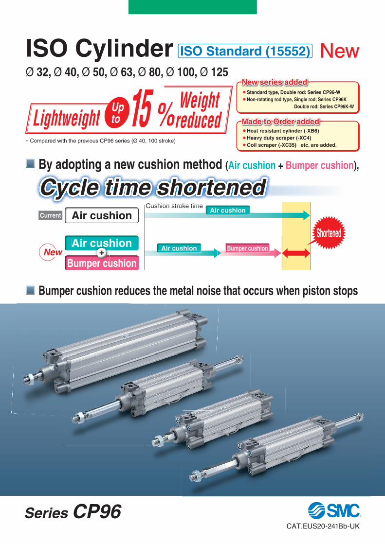
By adopting a new cushion method (Air cushion + Bumper cushion),
Bumper cushion reduces the metal noise that occurs when piston stops
Current
Air cushion
Air cushionAir cushion
Bumper cushion
Air cushion Bumper cushioncuuuusss
+
Cushion stroke time
Shortened
∗ Compared with the previous CP96 series (Ø 40, 100 stroke)
Cushion stroke time
Cycle time shortened
Lightweight 15 % Weight reduced
Upto
New
ISO CylinderØ 32, Ø 40, Ø 50, Ø 63, Ø 80, Ø 100, Ø 125
ISO Standard (15552)
Series CP96CAT.EUS20-241Bb-UK

New Series CP96
Combinedstructure
Rod end nut
can be screwed
up to TRP.
¡The cushion stroke time can now be reduced with the double
cushioning, which improves the cycle time.
¡The bumper cushion reduces the metal noise that occurs when
the piston stops at the end of the stroke.
Auto switch can be slid in.Auto switch mounting surface
Auto switch mounting
�Switch can be slid in for mounting.
�Groove for M9, A9 switches and CNOMO groove are
on all four sides. Max. four sides, slide-in mountable
Mountable from both the head end and the rod end.
Air cushion Bumper cushionB+
Auto switch
Auto switch mounting screw
Groove for the D-M9�, A9� type
CNOMO grooves
Mount a switch from the head
end for attaching to the CNOMO
groove on the port surfaces.
Bumper cushion Air cushion
TRP
Weight reduced
Bore size[mm]
CP96 Reduction rate
32 0.74 11 %
40 1.02 15 %
50 1.74 11 %
63 2.12 12 %
80 3.40 11 %
100 4.33 11 %
[kg]
Achieved weight reduction by changing rod cover shape
and piston structure
∗ Compared with the previous CP96 series (Ø 40, 100 stroke)
∗ Ø 125 maintains the structure
1
Series TypeBore size [mm]
32 40 50 63 80 100 125
Double acting, Single rod
Double acting, Double rod
Double acting, Single rod
Double acting, Double rod
Page
Page 3
Page 15
Non-rotating rodSeries CP96K
Series Variations
StandardSeries CP96
ndards CP96
n rotating rodes CP96K
d
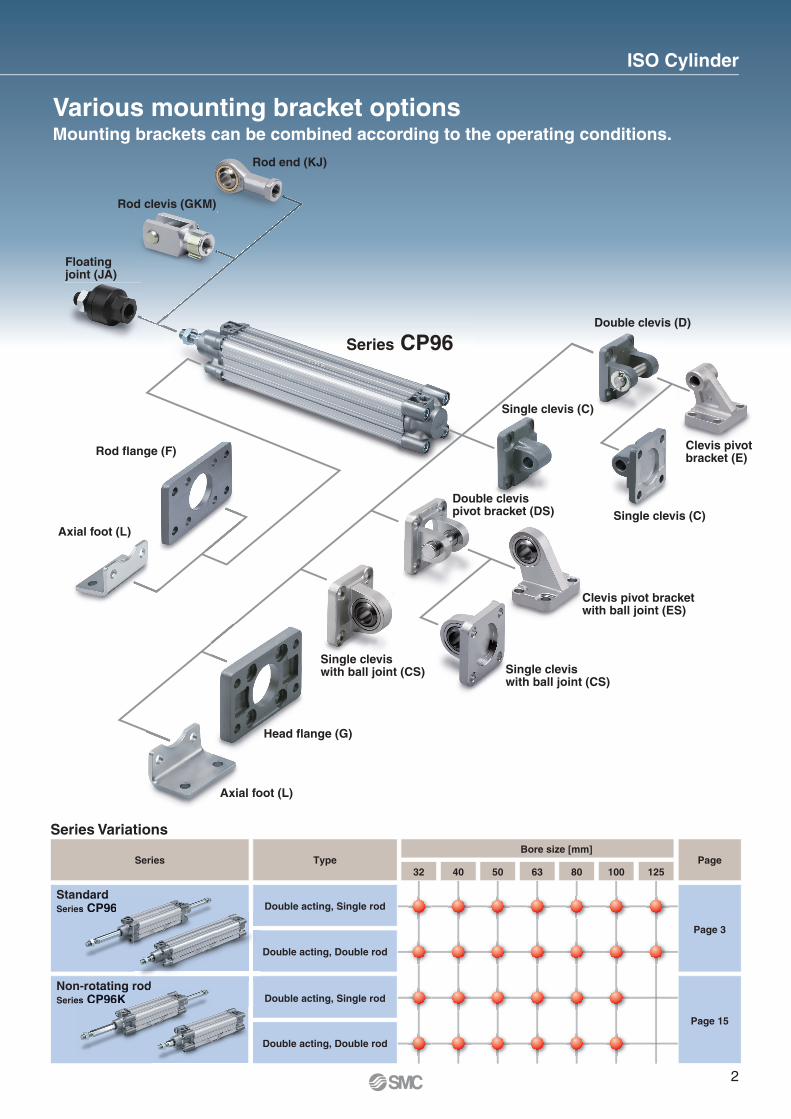
Various mounting bracket optionsMounting brackets can be combined according to the operating conditions.
Rod end (KJ)
Rod clevis (GKM)
Floatingjoint (JA)
Rod flange (F)
Axial foot (L)
Double clevis (D)
Clevis pivotbracket (E)
Single clevis (C)
Double clevispivot bracket (DS)
Clevis pivot bracketwith ball joint (ES)
Single cleviswith ball joint (CS)
Single cleviswith ball joint (CS)
Head flange (G)
Axial foot (L)
e ccllllllelevvis
Single clevis (C)
( )
ge ((F)
AAxia
HHHeHead fla
ISO Cylinder
Series CP96
2
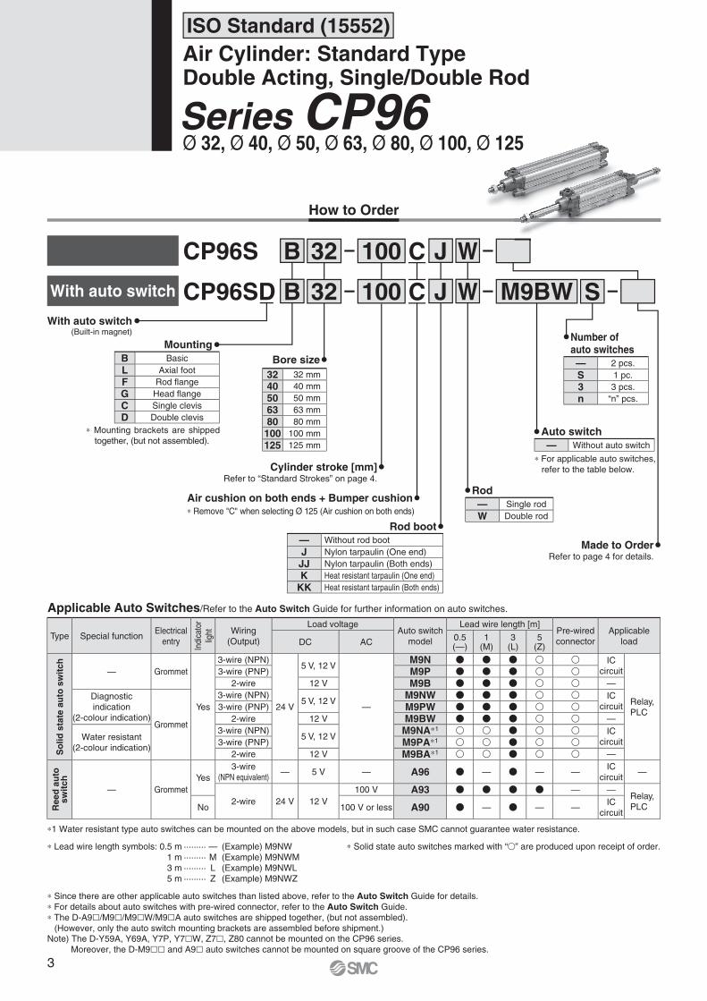
How to Order
CP96S B WJ32 100
CP96SD B WJ S32 100 M9BWC
C
Rod
Rod boot
Refer to page 4 for details.
Made to Order— Without rod boot
J Nylon tarpaulin (One end)
JJ Nylon tarpaulin (Both ends)
K Heat resistant tarpaulin (One end)
KK Heat resistant tarpaulin (Both ends)
— Single rod
W Double rod
With auto switch
With auto switch(Built-in magnet)
B Basic
L Axial foot
F Rod fl ange
G Head fl ange
C Single clevis
D Double clevis
Mounting
∗ Mounting brackets are shipped
together, (but not assembled).
ISO Standard (15552)
Air Cylinder: Standard TypeDouble Acting, Single/Double Rod
Ø 32, Ø 40, Ø 50, Ø 63, Ø 80, Ø 100, Ø 125Series CP96
Applicable Auto Switches/Refer to the Auto Switch Guide for further information on auto switches.
∗ Solid state auto switches marked with “�” are produced upon receipt of order.
∗1 Water resistant type auto switches can be mounted on the above models, but in such case SMC cannot guarantee water resistance.
∗ Lead wire length symbols: 0.5 m ········· — (Example) M9NW
1 m ········· M (Example) M9NWM
3 m ········· L (Example) M9NWL
5 m ········· Z (Example) M9NWZ
∗ Since there are other applicable auto switches than listed above, refer to the Auto Switch Guide for details.
∗ For details about auto switches with pre-wired connector, refer to the Auto Switch Guide.
∗ The D-A9�/M9�/M9�W/M9�A auto switches are shipped together, (but not assembled).
(However, only the auto switch mounting brackets are assembled before shipment.)Note) The D-Y59A, Y69A, Y7P, Y7�W, Z7�, Z80 cannot be mounted on the CP96 series.
Moreover, the D-M9�� and A9� auto switches cannot be mounted on square groove of the CP96 series.
Type Special functionElectrical
entry
Indi
cato
r
light Wiring
(Output)
Load voltageAuto switch
model
Lead wire length [m]Pre-wired
connector
Applicable
loadDC AC0.5(—)
1(M)
3(L)
5(Z)
So
lid
sta
te a
uto
sw
itc
h
— Grommet
Yes
3-wire (NPN)
24 V
5 V, 12 V
—
M9N � � � � � IC
circuit
Relay,
PLC
3-wire (PNP) M9P � � � � �2-wire 12 V M9B � � � � � —
Diagnostic
indication
(2-colour indication)Grommet
3-wire (NPN)5 V, 12 V
M9NW � � � � � IC
circuit3-wire (PNP) M9PW � � � � �2-wire 12 V M9BW � � � � � —
Water resistant
(2-colour indication)
3-wire (NPN)5 V, 12 V
M9NA∗1 � � � � � IC
circuit3-wire (PNP) M9PA∗1 � � � � �2-wire 12 V M9BA∗1 � � � � � —
Reed
au
tosw
itch
— Grommet
Yes
3-wire
(NPN equivalent)— 5 V — A96 � — � — —
IC
circuit—
2-wire 24 V 12 V
100 V A93 � � � � — —Relay,
PLCNo 100 V or less A90 � — � — —IC
circuit
Bore size
Cylinder stroke [mm]Refer to “Standard Strokes” on page 4.
— 2 pcs.
S 1 pc.
3 3 pcs.
n “n” pcs.
Number of auto switches
— Without auto switch
Auto switch
∗ For applicable auto switches,
refer to the table below.
Air cushion on both ends + Bumper cushion
32 32 mm
40 40 mm
50 50 mm
63 63 mm
80 80 mm
100 100 mm
125 125 mm
∗ Remove "C" when selecting Ø 125 (Air cushion on both ends)
3
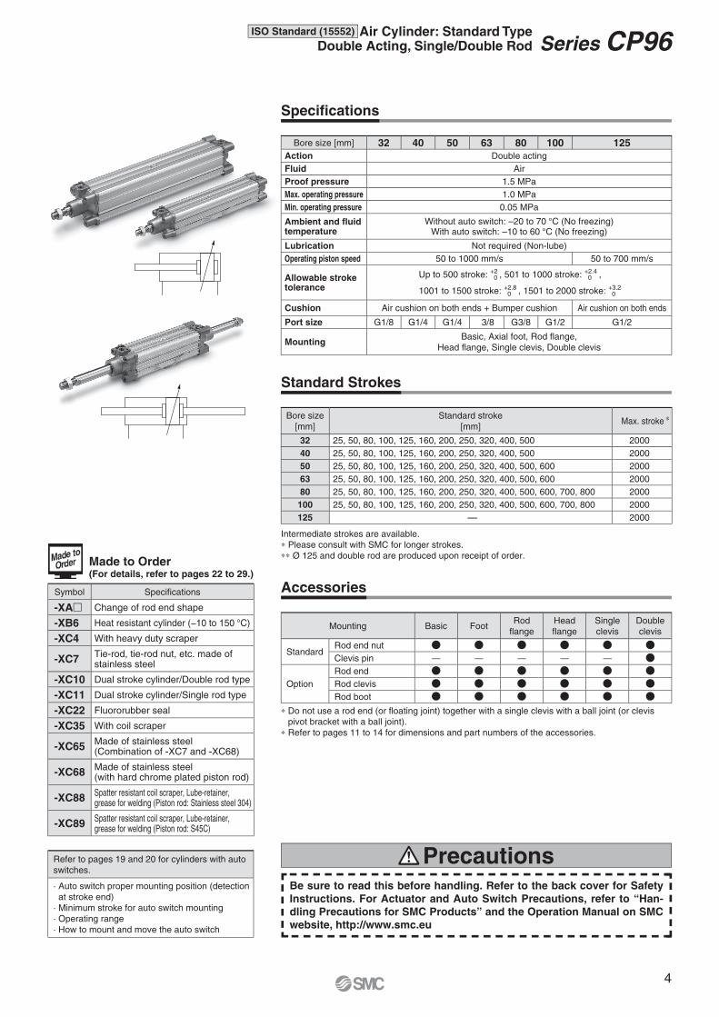
Made to Order(For details, refer to pages 22 to 29.)
Symbol Specifications
-XA� Change of rod end shape
-XB6 Heat resistant cylinder (−10 to 150 °C)
-XC4 With heavy duty scraper
-XC7Tie-rod, tie-rod nut, etc. made of stainless steel
-XC10 Dual stroke cylinder/Double rod type
-XC11 Dual stroke cylinder/Single rod type
-XC22 Fluororubber seal
-XC35 With coil scraper
-XC65Made of stainless steel (Combination of -XC7 and -XC68)
-XC68Made of stainless steel (with hard chrome plated piston rod)
-XC88Spatter resistant coil scraper, Lube-retainer, grease for welding (Piston rod: Stainless steel 304)
-XC89Spatter resistant coil scraper, Lube-retainer, grease for welding (Piston rod: S45C)
Refer to pages 19 and 20 for cylinders with auto
switches.
· Auto switch proper mounting position (detection
at stroke end)
· Minimum stroke for auto switch mounting
· Operating range
· How to mount and move the auto switch
Be sure to read this before handling. Refer to the back cover for Safety
Instructions. For Actuator and Auto Switch Precautions, refer to “Han-
dling Precautions for SMC Products” and the Operation Manual on SMC
website, http://www.smc.eu
Precautions
Bore size [mm] 32 40 50 63 80 100 125
Action Double acting
Fluid Air
Proof pressure 1.5 MPa
Max. operating pressure 1.0 MPa
Min. operating pressure 0.05 MPa
Ambient and fl uid temperature
Without auto switch: –20 to 70 °C (No freezing)With auto switch: –10 to 60 °C (No freezing)
Lubrication Not required (Non-lube)
Operating piston speed 50 to 1000 mm/s 50 to 700 mm/s
Allowable stroke tolerance
Up to 500 stroke: +2 0 , 501 to 1000 stroke: +2.4
0 ,
1001 to 1500 stroke: +2.8 0 , 1501 to 2000 stroke: +3.2
0
Cushion Air cushion on both ends + Bumper cushion Air cushion on both ends
Port size G1/8 G1/4 G1/4 3/8 G3/8 G1/2 G1/2
MountingBasic, Axial foot, Rod fl ange,
Head fl ange, Single clevis, Double clevis
Specifi cations
Standard Strokes
Intermediate strokes are available.
∗ Please consult with SMC for longer strokes.
∗∗ Ø 125 and double rod are produced upon receipt of order.
Accessories
∗ Do not use a rod end (or fl oating joint) together with a single clevis with a ball joint (or clevis
pivot bracket with a ball joint).
∗ Refer to pages 11 to 14 for dimensions and part numbers of the accessories.
Mounting Basic FootRod
fl ange
Head
fl ange
Single
clevis
Double
clevis
StandardRod end nut � � � � � �Clevis pin — — — — — �
Option
Rod end � � � � � �Rod clevis � � � � � �Rod boot � � � � � �
Bore size
[mm]
Standard stroke
[mm]Max. stroke ∗
32 25, 50, 80, 100, 125, 160, 200, 250, 320, 400, 500 2000
40 25, 50, 80, 100, 125, 160, 200, 250, 320, 400, 500 2000
50 25, 50, 80, 100, 125, 160, 200, 250, 320, 400, 500, 600 2000
63 25, 50, 80, 100, 125, 160, 200, 250, 320, 400, 500, 600 2000
80 25, 50, 80, 100, 125, 160, 200, 250, 320, 400, 500, 600, 700, 800 2000
100 25, 50, 80, 100, 125, 160, 200, 250, 320, 400, 500, 600, 700, 800 2000
125 — 2000
4
ISO Standard (15552) Air Cylinder: Standard TypeDouble Acting, Single/Double Rod Series CP96
OUT IN
1 10 100 1000 10000
10000
100
1
Ø 125
Ø 100
Ø 80
Ø 63
Ø 50
Ø 40
Ø 32
Maximum speed [mm/s]
Load m
ass [kg]
Bore
size
[mm]
Rod size
[mm]
Operating
direction
Piston
area[mm2]
Operating pressure [MPa]
0.2 0.3 0.4 0.5 0.6 0.7 0.8 0.9 1.0
32 12OUT 804 161 241 322 402 482 563 643 724 804
IN 691 138 207 276 346 415 484 553 622 691
40 16OUT 1257 251 377 503 629 754 880 1006 1131 1257
IN 1056 211 317 422 528 634 739 845 950 1056
50 20OUT 1963 393 589 785 982 1178 1374 1570 1767 1963
IN 1649 330 495 660 825 989 1154 1319 1484 1649
63 20OUT 3117 623 935 1247 1559 1870 2182 2494 2805 3117
IN 2803 561 841 1121 1402 1682 1962 2242 2523 2803
80 25OUT 5027 1005 1508 2011 2514 3016 3519 4022 4524 5027
IN 4536 907 1361 1814 2268 2722 3175 3629 4082 4536
100 25OUT 7854 1571 2356 3142 3927 4712 5498 6283 7068 7854
IN 7363 1473 2209 2945 3682 4418 5154 5890 6627 7363
125 32OUT 12272 2454 3682 4909 6136 7363 8590 9817 11045 12272
IN 11468 2294 3440 4587 5734 6881 8027 9174 10321 11468
Bore size [mm] 32 40 50 63 80 100 125
Basic weight
Basic 0.46 0.66 1.14 1.48 2.42 3.25 6.82
Foot 0.16 0.20 0.38 0.46 0.89 1.09 2.60
Flange 0.20 0.23 0.47 0.58 1.30 1.81 4.10
Single clevis 0.16 0.23 0.37 0.60 1.07 1.73 4.15
Double clevis 0.20 0.32 0.45 0.71 1.28 2.11 4.25
Additional weight
per 50 mm of strokeAll mounting brackets 0.14 0.18 0.30 0.32 0.49 0.54 0.84
AccessoriesRod end 0.07 0.11 0.22 0.40 1.20
Rod clevis 0.09 0.15 0.34 0.69 1.84
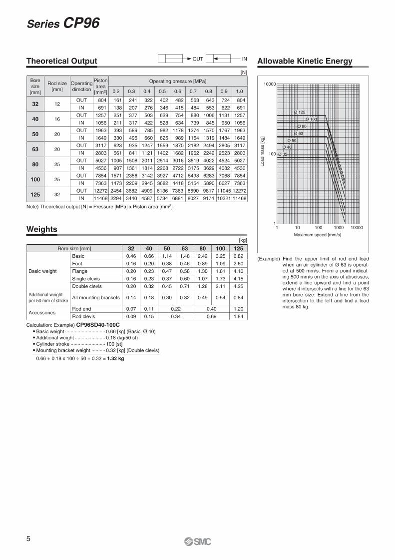
Note) Theoretical output [N] = Pressure [MPa] x Piston area [mm2]
[kg]
Theoretical Output Allowable Kinetic Energy
Weights
(Example) Find the upper limit of rod end load
when an air cylinder of Ø 63 is operat-
ed at 500 mm/s. From a point indicat-
ing 500 mm/s on the axis of abscissas,
extend a line upward and fi nd a point
where it intersects with a line for the 63
mm bore size. Extend a line from the
intersection to the left and fi nd a load
mass 80 kg.
Calculation: Example) CP96SD40-100C �Basic weight ····························· 0.66 [kg] (Basic, Ø 40)
�Additional weight ······················ 0.18 (kg/50 st)
�Cylinder stroke ························· 100 [st]
�Mounting bracket weight ·········· 0.32 [kg] (Double clevis)
0.66 + 0.18 x 100 ÷ 50 + 0.32 = 1.32 kg
[N]
5
Series CP96
Ø 80, Ø 100Ø 80, Ø 100
q e r y
u
t i w!2 !9 !4 !5 !6 !8 @2 !7 @0!3 @1
o !0
!1 !0
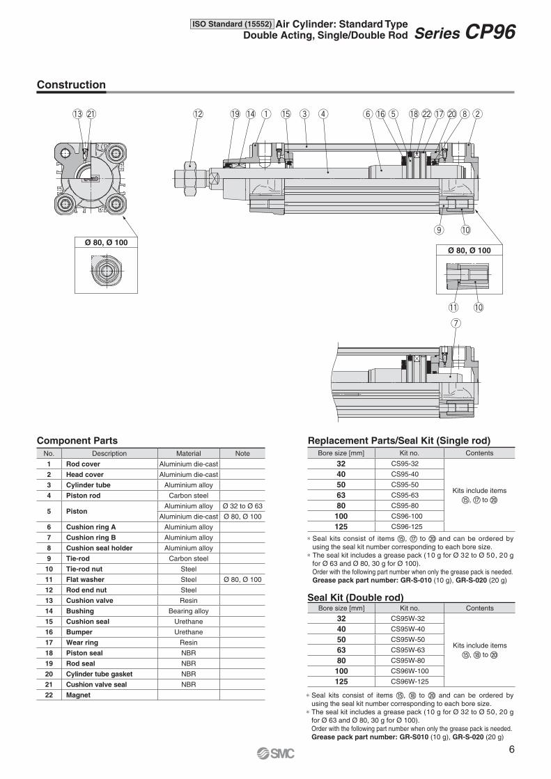
No. Description Material Note
1 Rod cover Aluminium die-cast
2 Head cover Aluminium die-cast
3 Cylinder tube Aluminium alloy
4 Piston rod Carbon steel
5 PistonAluminium alloy Ø 32 to Ø 63
Aluminium die-cast Ø 80, Ø 100
6 Cushion ring A Aluminium alloy
7 Cushion ring B Aluminium alloy
8 Cushion seal holder Aluminium alloy
9 Tie-rod Carbon steel
10 Tie-rod nut Steel
11 Flat washer Steel Ø 80, Ø 100
12 Rod end nut Steel
13 Cushion valve Resin
14 Bushing Bearing alloy
15 Cushion seal Urethane
16 Bumper Urethane
17 Wear ring Resin
18 Piston seal NBR
19 Rod seal NBR
20 Cylinder tube gasket NBR
21 Cushion valve seal NBR
22 Magnet
Component Parts
Construction
Bore size [mm] Kit no. Contents
32 CS95-32
Kits include items
�, � to �
40 CS95-40
50 CS95-50
63 CS95-63
80 CS95-80
100 CS96-100
125 CS96-125
Seal Kit (Double rod)
∗ Seal kits consist of items �, � to � and can be ordered by
using the seal kit number corresponding to each bore size.
∗ The seal kit includes a grease pack (10 g for Ø 32 to Ø 50, 20 g
for Ø 63 and Ø 80, 30 g for Ø 100).
Order with the following part number when only the grease pack is needed.
Grease pack part number: GR-S010 (10 g), GR-S-020 (20 g)
Bore size [mm] Kit no. Contents
32 CS95W-32
Kits include items
�, � to �
40 CS95W-40
50 CS95W-50
63 CS95W-63
80 CS95W-80
100 CS96W-100
125 CS96W-125
Replacement Parts/Seal Kit (Single rod)
∗ Seal kits consist of items �, � to � and can be ordered by
using the seal kit number corresponding to each bore size.
∗ The seal kit includes a grease pack (10 g for Ø 32 to Ø 50, 20 g
for Ø 63 and Ø 80, 30 g for Ø 100).
Order with the following part number when only the grease pack is needed.
Grease pack part number: GR-S-010 (10 g), GR-S-020 (20 g)
6
ISO Standard (15552) Air Cylinder: Standard TypeDouble Acting, Single/Double Rod Series CP96
Ø 80, Ø 100
Ø 32, Ø 40
Ø 80, Ø 100
E
R
ERø D
ø B
KK
Width across flats SW
2 x EE
PL
SL
PL2 x EE
port
Cushion valve
WB
WA
PL
ø B
WA
WB
2 x 4 x RT BG
ZZ + Stroke
L8 + StrokeH VA
G
BG2 x 4 x RT
L9
GWHA
BGL2
VDL12
With rod boot
ø d ø e
h
f
h + L8 + VA + Stroke
l
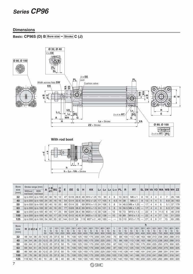
Bore
size
[mm]H Ø d Ø e f
l h
1to50
51to
100
101to
150
151to
200
201to
300
301to
400
401to
500
501to
600
601to
700
701to
800
801to
900
901to
1000
1to50
51to
100
101to
150
151to
200
201to
300
301to
400
401to
500
501to
600
601to
700
701to
800
801to
900
901to
1000
32 48 54 36 23 12.5 25 37.5 50 75 100 125 150 175 200 225 250 75 88 100 113 138 163 188 213 238 263 288 313
40 54 54 36 23 12.5 25 37.5 50 75 100 125 150 175 200 225 250 75 88 100 113 138 163 188 213 238 263 288 313
50 69 64 51 25 12.5 25 37.5 50 75 100 125 150 175 200 225 250 87 100 112 125 150 175 200 225 250 275 300 325
63 69 64 51 25 12.5 25 37.5 50 75 100 125 150 175 200 225 250 87 100 112 125 150 175 200 225 250 275 300 325
80 86 68 56 30 12.5 25 37.5 50 75 100 125 150 175 200 225 250 103 116 128 141 166 191 216 241 266 291 316 341
100 91 76 56 32 12.5 25 37.5 50 75 100 125 150 175 200 225 250 103 116 128 141 166 191 216 241 266 291 316 341
125 119 82 75 40 10 20 30 40 60 80 100 120 140 160 180 200 130 140 150 160 180 200 220 240 260 280 300 320
Bore
size
[mm]
Stroke range [mm]A
Ø Bd11
BGØ D
E EE G H KK L2 L8 L9 L12 PL R RT SL SW VA VD WA WB WH ZZWithout rod boot
Withrod boot
32 Up to 2000 Up to 1000 22 30 16 12 47 G1/8 28.9 48 M10 x 1.25 15 94 4 6 13 32.5 M6 x 1 8 10 4 4 4 7 26 146
40 Up to 2000 Up to 1000 24 35 16 16 54 G1/4 32.6 54 M12 x 1.25 17 105 4 6.5 14 38 M6 x 1 8 13 4 4 5 8.9 30 163
50 Up to 2000 Up to 1000 32 40 16 20 66 G1/4 32 69 M16 x 1.5 24 106 5 8 14 46.5 M8 x 1.25 — 17 4 4 6 5.1 37 179
63 Up to 2000 Up to 1000 32 45 16 20 77 G3/8 38.6 69 M16 x 1.5 24 121 5 8 16 56.5 M8 x 1.25 — 17 4 4 9 6.3 37 194
80 Up to 2000 Up to 1000 40 45 17 25 99 G3/8 38.4 86 M20 x 1.5 30 128 — 10 16 72 M10 x 1.5 — 22 4 4 11.5 6 46 218
100 Up to 2000 Up to 1000 40 55 17 25 118 G1/2 42.9 91 M20 x 1.5 32 138 — 10 18 89 M10 x 1.5 — 22 4 4 17 10 51 233
125 Up to 2000 Up to 1000 54 60 20 32 144 G1/2 58 119 M27 x 2 40 160 — — 19 110 M12 x 1.75 — 27 6 6 17 15 65 285
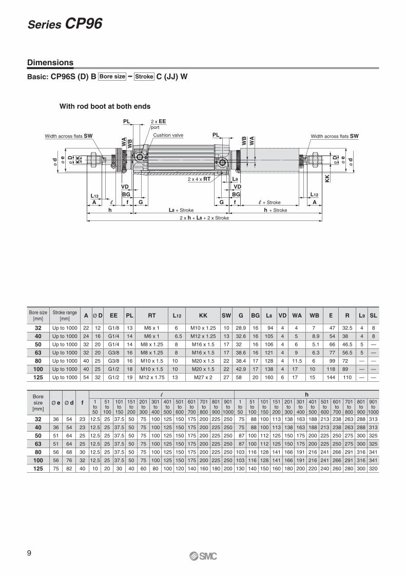
Dimensions
Basic: CP96S (D) B C (J)Bore size Stroke
7
Series CP96
Ø 32, Ø 40
Ø 80, Ø 100Ø 80, Ø 100
With rod boot at one end
RE
E
R
KK
ø D
ø B
Width across flats SW
WB
WA
2 x EE
SLPL
Cushion valve
2 x EEport
PL BG2 x 4 x RT
Width across flats SW
ø B
ø D
KK
VDL12
L2 BG
GWHA
H
G
ZY + 2 x Stroke
L8 + Stroke
2 x 4 x RT
L2BG
H + Stroke
AWH + Stroke
VD
L9
PL
WA
WB
L12
ø d
l
ø e
h + L8 + H + 2 x Stroke
h
f
Bore size
[mm]
Stroke range
[mm]A
Ø Bd11
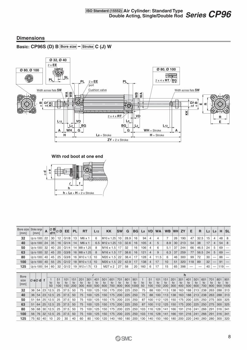
Ø D EE PL RT L12 KK SW G BG L8 VD WA WB WH ZY E R L2 L9 H SL
32 Up to 1000 22 30 12 G1/8 13 M6 x 1 6 M10 x 1.25 10 28.9 16 94 4 4 7 26 190 47 32.5 15 4 48 8
40 Up to 1000 24 35 16 G1/4 14 M6 x 1 6.5 M12 x 1.25 13 32.6 16 105 4 5 8.9 30 213 54 38 17 4 54 8
50 Up to 1000 32 40 20 G1/4 14 M8 x 1.25 8 M16 x 1.5 17 32 16 106 4 6 5.1 37 244 66 46.5 24 5 69 —
63 Up to 1000 32 45 20 G3/8 16 M8 x 1.25 8 M16 x 1.5 17 38.6 16 121 4 9 6.3 37 259 77 56.5 24 5 69 —
80 Up to 1000 40 45 25 G3/8 16 M10 x 1.5 10 M20 x 1.5 22 38.4 17 128 4 11.5 6 46 300 99 72 30 — 86 —
100 Up to 1000 40 55 25 G1/2 18 M10 x 1.5 10 M20 x 1.5 22 42.9 17 138 4 17 10 51 320 118 89 32 — 91 —
125 Up to 1000 54 60 32 G1/2 19 M12 x 1.75 13 M27 x 2 27 58 20 160 6 17 15 65 398 — — 40 — 119 —
Bore
size
[mm]Ø eØ d f
l h
1to50
51to
100
101to
150
151to
200
201to
300
301to
400
401to
500
501to
600
601to
700
701to
800
801to
900
901to
1000
1to50
51to
100
101to
150
151to
200
201to
300
301to
400
401to
500
501to
600
601to
700
701to
800
801to
900
901to
1000
32 36 54 23 12.5 25 37.5 50 75 100 125 150 175 200 225 250 75 88 100 113 138 163 188 213 238 263 288 313
40 36 54 23 12.5 25 37.5 50 75 100 125 150 175 200 225 250 75 88 100 113 138 163 188 213 238 263 288 313
50 51 64 25 12.5 25 37.5 50 75 100 125 150 175 200 225 250 87 100 112 125 150 175 200 225 250 275 300 325
63 51 64 25 12.5 25 37.5 50 75 100 125 150 175 200 225 250 87 100 112 125 150 175 200 225 250 275 300 325
80 56 68 30 12.5 25 37.5 50 75 100 125 150 175 200 225 250 103 116 128 141 166 191 216 241 266 291 316 341
100 56 76 32 12.5 25 37.5 50 75 100 125 150 175 200 225 250 103 116 128 141 166 191 216 241 266 291 316 341
125 75 82 40 10 20 30 40 60 80 100 120 140 160 180 200 130 140 150 160 180 200 220 240 260 280 300 320
Dimensions
Basic: CP96S (D) B C (J) WBore size Stroke
8
ISO Standard (15552) Air Cylinder: Standard TypeDouble Acting, Single/Double Rod Series CP96
ø d
ø d
l
KK
ø D
ø e
Width across flats SW
PL 2 x EEport
Cushion valveW
BW
A
PL
WB
WA Width across flats SW
ø D
ø e
KK
BG
VD
GfAL12
h
2 x h + L8 + 2 x Stroke
L8 + Stroke h + Stroke
l + StrokefG
2 x 4 x RT L9
VD
BG
A
L12
With rod boot at both ends
Bore size
[mm]
Stroke range
[mm]A Ø D EE PL RT L12 KK SW G BG L8 VD WA WB E R L9 SL
32 Up to 1000 22 12 G1/8 13 M6 x 1 6 M10 x 1.25 10 28.9 16 94 4 4 7 47 32.5 4 8
40 Up to 1000 24 16 G1/4 14 M6 x 1 6.5 M12 x 1.25 13 32.6 16 105 4 5 8.9 54 38 4 8
50 Up to 1000 32 20 G1/4 14 M8 x 1.25 8 M16 x 1.5 17 32 16 106 4 6 5.1 66 46.5 5 —
63 Up to 1000 32 20 G3/8 16 M8 x 1.25 8 M16 x 1.5 17 38.6 16 121 4 9 6.3 77 56.5 5 —
80 Up to 1000 40 25 G3/8 16 M10 x 1.5 10 M20 x 1.5 22 38.4 17 128 4 11.5 6 99 72 — —
100 Up to 1000 40 25 G1/2 18 M10 x 1.5 10 M20 x 1.5 22 42.9 17 138 4 17 10 118 89 — —
125 Up to 1000 54 32 G1/2 19 M12 x 1.75 13 M27 x 2 27 58 20 160 6 17 15 144 110 — —
Bore
size
[mm]Ø e Ø d f
l h
1to50
51to
100
101to
150
151to
200
201to
300
301to
400
401to
500
501to
600
601to
700
701to
800
801to
900
901to
1000
1to50
51to
100
101to
150
151to
200
201to
300
301to
400
401to
500
501to
600
601to
700
701to
800
801to
900
901to
1000
32 36 54 23 12.5 25 37.5 50 75 100 125 150 175 200 225 250 75 88 100 113 138 163 188 213 238 263 288 313
40 36 54 23 12.5 25 37.5 50 75 100 125 150 175 200 225 250 75 88 100 113 138 163 188 213 238 263 288 313
50 51 64 25 12.5 25 37.5 50 75 100 125 150 175 200 225 250 87 100 112 125 150 175 200 225 250 275 300 325
63 51 64 25 12.5 25 37.5 50 75 100 125 150 175 200 225 250 87 100 112 125 150 175 200 225 250 275 300 325
80 56 68 30 12.5 25 37.5 50 75 100 125 150 175 200 225 250 103 116 128 141 166 191 216 241 266 291 316 341
100 56 76 32 12.5 25 37.5 50 75 100 125 150 175 200 225 250 103 116 128 141 166 191 216 241 266 291 316 341
125 75 82 40 10 20 30 40 60 80 100 120 140 160 180 200 130 140 150 160 180 200 220 240 260 280 300 320
Dimensions
Basic: CP96S (D) B C (JJ) WBore size Stroke
9
Series CP96
AH
E1
TR
XA + Stroke
SA + StrokeAOAT
4 x ø AB
AO
RE2
UF
TF
4 x FB
W MF
ZF + Stroke
MF
XD + Stroke
L MR
CD
EW
EB
UB
CB
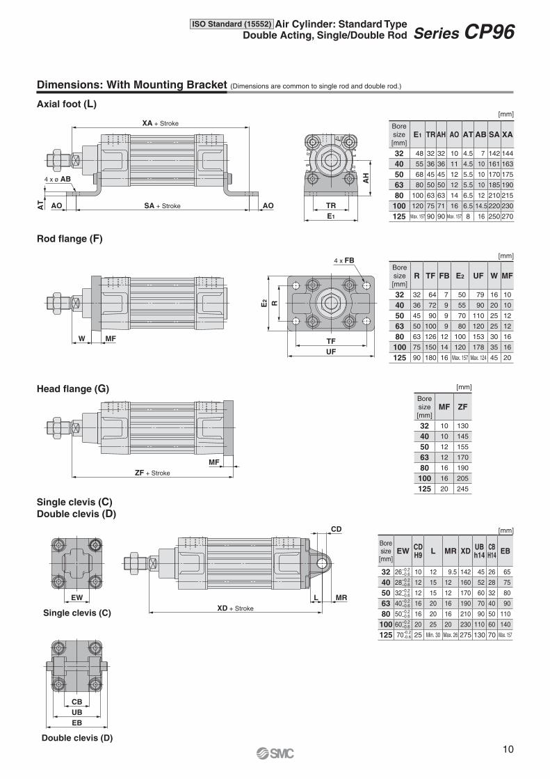
Dimensions: With Mounting Bracket (Dimensions are common to single rod and double rod.)
Axial foot (L)
Rod fl ange (F)
Single clevis (C)
Double clevis (D)
Head fl ange (G)
Bore size[mm]
EWCDH9
L MR XDUBh14
CBH14
EB
32 26–0.2–0.6 10 12 9.5 142 45 26 65
40 28–0.2–0.6 12 15 12 160 52 28 75
50 32–0.2–0.6 12 15 12 170 60 32 80
63 40–0.2–0.6 16 20 16 190 70 40 90
80 50–0.2–0.6 16 20 16 210 90 50 110
100 60–0.2–0.6 20 25 20 230 110 60 140
125 70 25 Min. 30 Max. 26 275 130 70 Max. 157
[mm]
[mm]
[mm]
[mm]
Single clevis (C)
Double clevis (D)
Bore
size
[mm]E1 TR AH AO AT AB SA XA
32 48 32 32 10 4.5 7 142 144
40 55 36 36 11 4.5 10 161 163
50 68 45 45 12 5.5 10 170 175
63 80 50 50 12 5.5 10 185 190
80 100 63 63 14 6.5 12 210 215
100 120 75 71 16 6.5 14.5 220 230
125 Max. 157 90 90 Max. 157 8 16 250 270
Bore
size
[mm]R TF FB E2 UF W MF
32 32 64 7 50 79 16 10
40 36 72 9 55 90 20 10
50 45 90 9 70 110 25 12
63 50 100 9 80 120 25 12
80 63 126 12 100 153 30 16
100 75 150 14 120 178 35 16
125 90 180 16 Max. 157 Max. 124 45 20
Bore
size
[mm]MF ZF
32 10 130
40 10 145
50 12 155
63 12 170
80 16 190
100 16 205
125 20 245
-0.2-0.6
10
ISO Standard (15552) Air Cylinder: Standard TypeDouble Acting, Single/Double Rod Series CP96
R2
TG
TG
/2
E
TRA
H
AT
AUAO
ø AB
FB
ø D
RE
UF
TF
TG
TG
MF
L4
øC
DH
9
l2
l1
ø ø
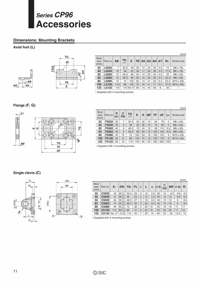
Bore size[mm]
Part no. E1 EW TG1 FL l1 L l2 Ø d1Ø
CDMR Ø d2 R1
32 C5032 45 26–0.2–0.6 32.5 22 5 12 5.5 30 10 9.5 6.6 6.5
40 C5040 51 28–0.2–0.6 38 25 5 15 5.5 35 12 12 6.6 6.5
50 C5050 64 32–0.2–0.6 46.5 27 5 15 6.5 40 12 12 9 8.5
63 C5063 74 40–0.2–0.6 56.5 32 5 20 6.5 45 16 16 9 8.5
80 C5080 94 50–0.2–0.6 72 36 5 20 10 45 16 16 11 11
100 C5100 113 60–0.2–0.6 89 41 5 25 10 55 20 20 11 12
125 C5125 Max. 157 70 110 50 7 30 10 60 25 26 13.5 10
∗ Supplied with 4 mounting screws.
[mm]
Boresize[mm]
Part no. AB TG±0.2
E TR AO AU AH AT R2 Screw size
32 L5032 7 32.5 48 32 10 24 32 4.5 15 M6 x 16L
40 L5040 10 38 55 36 11 28 36 4.5 17.5 M6 x 16L
50 L5050 10 46.5 68 45 12 32 45 5.5 20 M8 x 20L
63 L5063 10 56.5 80 50 12 32 50 5.5 22.5 M8 x 20L
80 L5080 12 72 100 63 14 41 63 6.5 22.5 M10 x 20L
100 L5100 14.5 89 120 75 16 41 71 6.5 27.5 M10 x 20L
125 L5125 116 110 Max.157 90 14 45 90 8 30 —
Boresize[mm]
Part no.D
H11Ø
FBTG±0.2
E R MF TF UF L4 Screw size
32 F5032 30 7 32.5 50 32 10 64 79 5 M6 x 20L
40 F5040 35 9 38 55 36 10 72 90 5 M6 x 20L
50 F5050 40 9 46.5 70 45 12 90 110 6.5 M8 x 20L
63 F5063 45 9 56.5 80 50 12 100 120 6.5 M8 x 20L
80 F5080 45 12 72 100 63 16 126 153 9 M10 x 25L
100 F5100 55 14 89 120 75 16 150 178 9 M10 x 25L
125 F5125 60 16 110 140 90 20 180 205 105 —
[mm]
∗ Supplied with 4 mounting screws.
∗ Supplied with 4 mounting screws.
[mm]
-0.2-0.6
Dimensions: Mounting Brackets
Axial foot (L)
Flange (F, G)
Single clevis (C)
Series CP96
Accessories
11
øø
l2
l1
ø
Ø
Ø ØØ
R
l3
l1ø
ø
ø
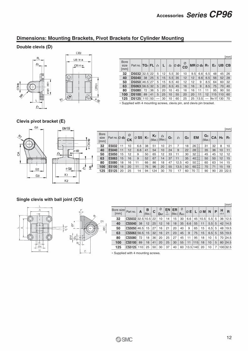
Bore size[mm]
Part no. Ø d2Ø
CKØ S5 K1
K2
(Max.)l3
(Max.)G1 l1 G2 EM
G3
(Max.)CA H6 R1
32 E5032 11 10 6.6 38 51 10 21 7 18 26–0.2–0.6 31 32 8 10
40 E5040 11 12 6.6 41 54 10 24 9 22 28–0.2–0.6 35 36 10 11
50 E5050 15 12 9 50 65 12 33 11 30 32–0.2–0.6 45 45 12 12
63 E5063 15 16 9 52 67 14 37 11 35 40–0.2–0.6 50 50 12 15
80 E5080 18 16 11 66 86 18 47 12.5 40 50–0.2–0.6 60 63 14 15
100 E5100 18 20 11 76 96 20 55 13.5 50 60–0.2–0.6 70 71 15 19
125 E5125 20 25 14 94 124 30 70 17 60 70 90 90 20 22.5
[mm]
Boresize[mm]
Part no. TG1 FL l1 L l2 Ø d1Ø
CDMR Ø d2 R1 E2 UB CB
32 D5032 32.5 22 5 12 5.5 30 10 9.5 6.6 6.5 48 45 26
40 D5040 38 25 5 15 5.5 35 12 12 6.6 6.5 56 52 28
50 D5050 46.5 27 5 15 6.5 40 12 12 9 8.5 64 60 32
63 D5063 56.5 32 5 20 6.5 45 16 16 9 8.5 75 70 40
80 D5080 72 36 5 20 10 45 16 16 11 11 95 90 50
100 D5100 89 41 5 25 10 55 20 20 11 12 115 110 60
125 D5125 110 50 — 30 10 60 25 25 13.5 — Max.157 130 70
[mm]
∗ Supplied with 4 mounting screws, clevis pin, and clevis pin bracket.
[mm]
-0.5-1.5
Bore size[mm]
Part no. AB
(Max.)C
Ø
DH7
EN 0–0.1
ER(Max.)
Ø
FH11Ø E L Ø M N P H
±0.5R
32 CS5032 32.5 10.5 22 10 14 15 30 6.6 45 10.5 5.5 5 36 12.5
40 CS5040 38 12 25 12 16 18 35 6.6 55 11 5.5 5 42 14.5
50 CS5050 46.5 15 27 16 21 20 40 9 65 15 6.5 5 48 19.5
63 CS5063 56.5 15 32 16 21 23 45 9 75 15 6.5 5 55 19.5
80 CS5080 72 18 36 20 25 27 45 11 95 18 10 5 70 24.5
100 CS5100 89 18 41 20 25 30 55 11 115 18 10 5 80 24.5
125 CS5125 110 25 50 30 37 40 60 13.5 140 20 10 7 100 32.5
∗ Supplied with 4 mounting screws.
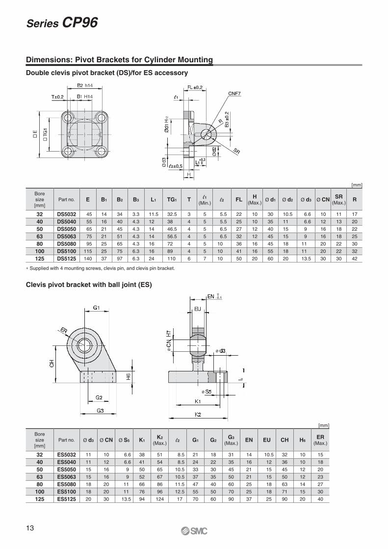
Dimensions: Mounting Brackets, Pivot Brackets for Cylinder Mounting
Double clevis (D)
Clevis pivot bracket (E)
Single clevis with ball joint (CS)
12
Accessories Series CP96
ø ø
ø
Ø
l1
l2L1
+0,30
Ø
Ø
,
,
Bore
size
[mm]
Part no. E B1 B2 B3 L1 TG1 T l1(Min.)
l2 FLH
(Max.)Ø d1 Ø d2 Ø d3 Ø CN
SR(Max.)
R
32 DS5032 45 14 34 3.3 11.5 32.5 3 5 5.5 22 10 30 10.5 6.6 10 11 17
40 DS5040 55 16 40 4.3 12 38 4 5 5.5 25 10 35 11 6.6 12 13 20
50 DS5050 65 21 45 4.3 14 46.5 4 5 6.5 27 12 40 15 9 16 18 22
63 DS5063 75 21 51 4.3 14 56.5 4 5 6.5 32 12 45 15 9 16 18 25
80 DS5080 95 25 65 4.3 16 72 4 5 10 36 16 45 18 11 20 22 30
100 DS5100 115 25 75 6.3 16 89 4 5 10 41 16 55 18 11 20 22 32
125 DS5125 140 37 97 6.3 24 110 6 7 10 50 20 60 20 13.5 30 30 42
Bore
size
[mm]
Part no. Ø d3 Ø CN Ø S5 K1K2
(Max.)l2 G1 G2
G3
(Max.)EN EU CH H6
ER(Max.)
32 ES5032 11 10 6.6 38 51 8.5 21 18 31 14 10.5 32 10 15
40 ES5040 11 12 6.6 41 54 8.5 24 22 35 16 12 36 10 18
50 ES5050 15 16 9 50 65 10.5 33 30 45 21 15 45 12 20
63 ES5063 15 16 9 52 67 10.5 37 35 50 21 15 50 12 23
80 ES5080 18 20 11 66 86 11.5 47 40 60 25 18 63 14 27
100 ES5100 18 20 11 76 96 12.5 55 50 70 25 18 71 15 30
125 ES5125 20 30 13.5 94 124 17 70 60 90 37 25 90 20 40
∗ Supplied with 4 mounting screws, clevis pin, and clevis pin bracket.
Dimensions: Pivot Brackets for Cylinder Mounting
Double clevis pivot bracket (DS)/for ES accessory
Clevis pivot bracket with ball joint (ES)
[mm]
[mm]
13
Series CP96
ø
l1
ø
l
l3
ø
Bore size
[mm]Part no. e b d
Ø f h11
(Shaft)
Ø f H9
(Hole)l1 c
(Min.)
a(Max.)
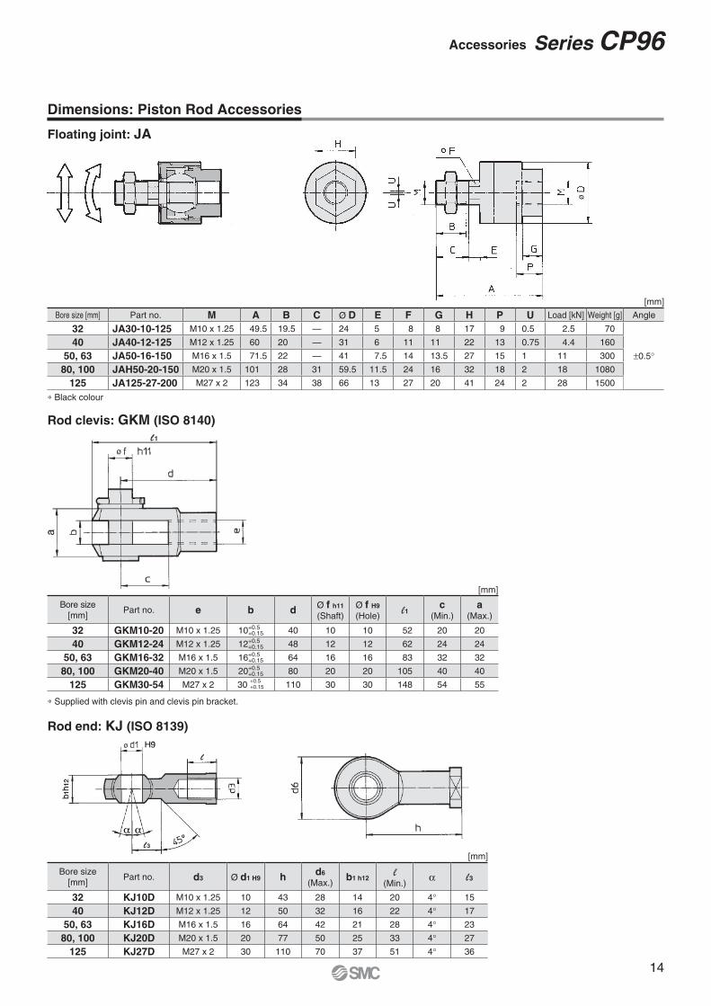
32 GKM10-20 M10 x 1.25 10+0.5+0.15 40 10 10 52 20 20
40 GKM12-24 M12 x 1.25 12+0.5+0.15 48 12 12 62 24 24
50, 63 GKM16-32 M16 x 1.5 16+0.5+0.15 64 16 16 83 32 32
80, 100 GKM20-40 M20 x 1.5 20+0.5+0.15 80 20 20 105 40 40
125 GKM30-54 M27 x 2 30 110 30 30 148 54 55
Bore size
[mm]Part no. d3 Ø d1 H9 h
d6
(Max.)b1 h12
l(Min.)
α l3
32 KJ10D M10 x 1.25 10 43 28 14 20 4° 15
40 KJ12D M12 x 1.25 12 50 32 16 22 4° 17
50, 63 KJ16D M16 x 1.5 16 64 42 21 28 4° 23
80, 100 KJ20D M20 x 1.5 20 77 50 25 33 4° 27
125 KJ27D M27 x 2 30 110 70 37 51 4° 36
[mm]
Bore size [mm] Part no. M A B C Ø D E F G H P U Load [kN] Weight [g] Angle
32 JA30-10-125 M10 x 1.25 49.5 19.5 — 24 5 8 8 17 9 0.5 2.5 70
±0.5°40 JA40-12-125 M12 x 1.25 60 20 — 31 6 11 11 22 13 0.75 4.4 160
50, 63 JA50-16-150 M16 x 1.5 71.5 22 — 41 7.5 14 13.5 27 15 1 11 300
80, 100 JAH50-20-150 M20 x 1.5 101 28 31 59.5 11.5 24 16 32 18 2 18 1080
125 JA125-27-200 M27 x 2 123 34 38 66 13 27 20 41 24 2 28 1500
∗ Black colour
Rod clevis: GKM (ISO 8140)
Rod end: KJ (ISO 8139)
Dimensions: Piston Rod Accessories
Floating joint: JA
∗ Supplied with clevis pin and clevis pin bracket.
[mm]
[mm]
+0.5+0.15
14
Accessories Series CP96

How to Order
CP96K B C W32
Rod
100
CP96KD B C SW32 100 M9BW
— Single rod
W Double rod
∗1 Water resistant type auto switches can be mounted on the above models, but in such case SMC cannot guarantee water resistance.
Please contact SMC regarding water resistant types with the above model numbers.
∗ Lead wire length symbols: 0.5 m ········· — (Example) M9NW
1 m ········· M (Example) M9NWM
3 m ········· L (Example) M9NWL
5 m ········· Z (Example) M9NWZ
∗ Since there are other applicable auto switches than listed above, refer to Auto Switch Guide for details.
∗ For details about auto switches with pre-wired connector, refer to Auto Switch Guide.
∗ The D-A9�/M9�/M9�W/M9�AL auto switches are shipped together, (but not assembled).
(However, only the auto switch mounting brackets are assembled before shipment.)Note) The D-Y59A, Y69A, Y7P, Y7�W, Z7�, Z80 cannot be mounted on the CP96 series.
Moreover, the D-M9�� and A9� auto switches cannot be mounted on square groove of the CP96 series.
— 2 pcs.
S 1 pc.
3 3 pcs.
n “n” pcs.
32 32 mm
40 40 mm
50 50 mm
63 63 mm
80 80 mm
100 100 mm
Bore size
With auto switch
Number of auto switches
Cylinder stroke [mm]Refer to “Maximum
Strokes” on page 16.
— Without auto switch
Auto switch
∗ For applicable auto switches,
refer to the table below.
Air cushion on both ends + Bumper cushion
With auto switch(Built-in magnet)
B Basic
L Axial foot
F Rod fl ange
G Head fl ange
C Single clevis
D Double clevis
Mounting
∗ Mounting brackets are shipped
together, (but not assembled).
ISO (15552) Standard
Air Cylinder: Non-rotating Rod TypeDouble Acting, Single/Double Rod
Ø 32, Ø 40, Ø 50, Ø 63, Ø 80, Ø 100Series CP96K
Applicable Auto Switches/Tie-rod mounting
∗ Solid state auto switches marked with “�” are produced upon receipt of order.
Type Special functionElectrical
entry
Indi
cato
r
light Wiring
(Output)
Load voltageAuto switch
model
Lead wire length [m]Pre-wired
connector
Applicable
loadDC AC0.5(—)
1(M)
3(L)
5(Z)
So
lid
sta
te a
uto
sw
itc
h
— Grommet
Yes
3-wire (NPN)
24 V
5 V, 12 V
—
M9N � � � � � IC
circuit
Relay,
PLC
3-wire (PNP) M9P � � � � �2-wire 12 V M9B � � � � � —
Diagnostic
indication
(2-colour indication)Grommet
3-wire (NPN)5 V, 12 V
M9NW � � � � � IC
circuit3-wire (PNP) M9PW � � � � �2-wire 12 V M9BW � � � � � —
Water resistant
(2-colour indication)
3-wire (NPN)5 V, 12 V
M9NA∗1 � � � � � IC
circuit3-wire (PNP) M9PA∗1 � � � � �2-wire 12 V M9BA∗1 � � � � � —
Reed
au
tosw
itch
— Grommet
Yes
3-wire
(NPN equivalent)— 5 V — A96 � — � — —
IC
circuit—
2-wire 24 V 12 V
100 V A93 � � � � — —Relay,
PLCNo 100 V or less A90 � — � — —IC
circuit
15
Intermediate strokes are available.
∗ Please consult with SMC for longer strokes.
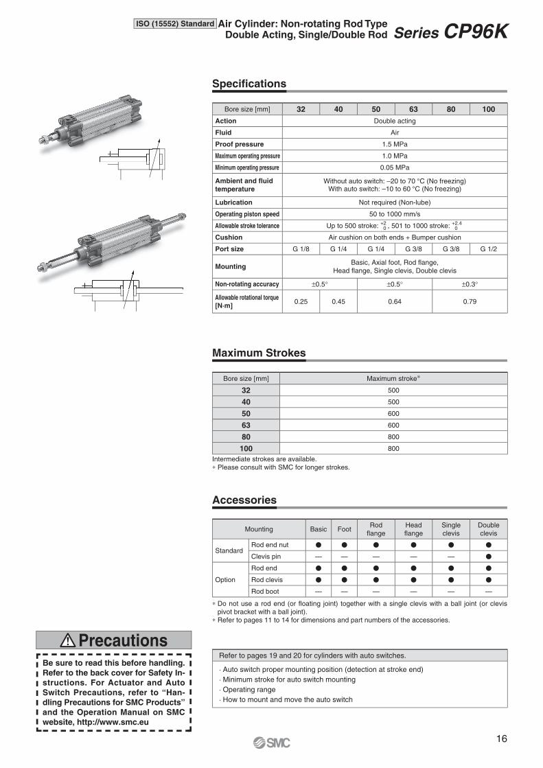
Specifi cations
Maximum Strokes
Accessories
∗ Do not use a rod end (or fl oating joint) together with a single clevis with a ball joint (or clevis
pivot bracket with a ball joint).
∗ Refer to pages 11 to 14 for dimensions and part numbers of the accessories.
Bore size [mm] 32 40 50 63 80 100
Action Double acting
Fluid Air
Proof pressure 1.5 MPa
Maximum operating pressure 1.0 MPa
Minimum operating pressure 0.05 MPa
Ambient and fluid
temperatureWithout auto switch: –20 to 70 °C (No freezing)
With auto switch: –10 to 60 °C (No freezing)
Lubrication Not required (Non-lube)
Operating piston speed 50 to 1000 mm/s
Allowable stroke tolerance Up to 500 stroke: +2 0 , 501 to 1000 stroke: +2.4
0
Cushion Air cushion on both ends + Bumper cushion
Port size G 1/8 G 1/4 G 1/4 G 3/8 G 3/8 G 1/2
MountingBasic, Axial foot, Rod flange,
Head flange, Single clevis, Double clevis
Non-rotating accuracy ±0.5° ±0.5° ±0.3°
Allowable rotational torque
[N·m]0.25 0.45 0.64 0.79
Bore size [mm] Maximum stroke∗
32 500
40 500
50 600
63 600
80 800
100 800
Mounting Basic FootRod
flange
Head
flange
Single
clevis
Double
clevis
StandardRod end nut � � � � � �
Clevis pin — — — — — �
Option
Rod end � � � � � �
Rod clevis � � � � � �
Rod boot — — — — — —
Be sure to read this before handling.
Refer to the back cover for Safety In-
structions. For Actuator and Auto
Switch Precautions, refer to “Han-
dling Precautions for SMC Products”
and the Operation Manual on SMC
website, http://www.smc.eu
PrecautionsRefer to pages 19 and 20 for cylinders with auto switches.
· Auto switch proper mounting position (detection at stroke end)
· Minimum stroke for auto switch mounting
· Operating range
· How to mount and move the auto switch
16
ISO (15552) Standard Air Cylinder: Non-rotating Rod TypeDouble Acting, Single/Double Rod Series CP96K
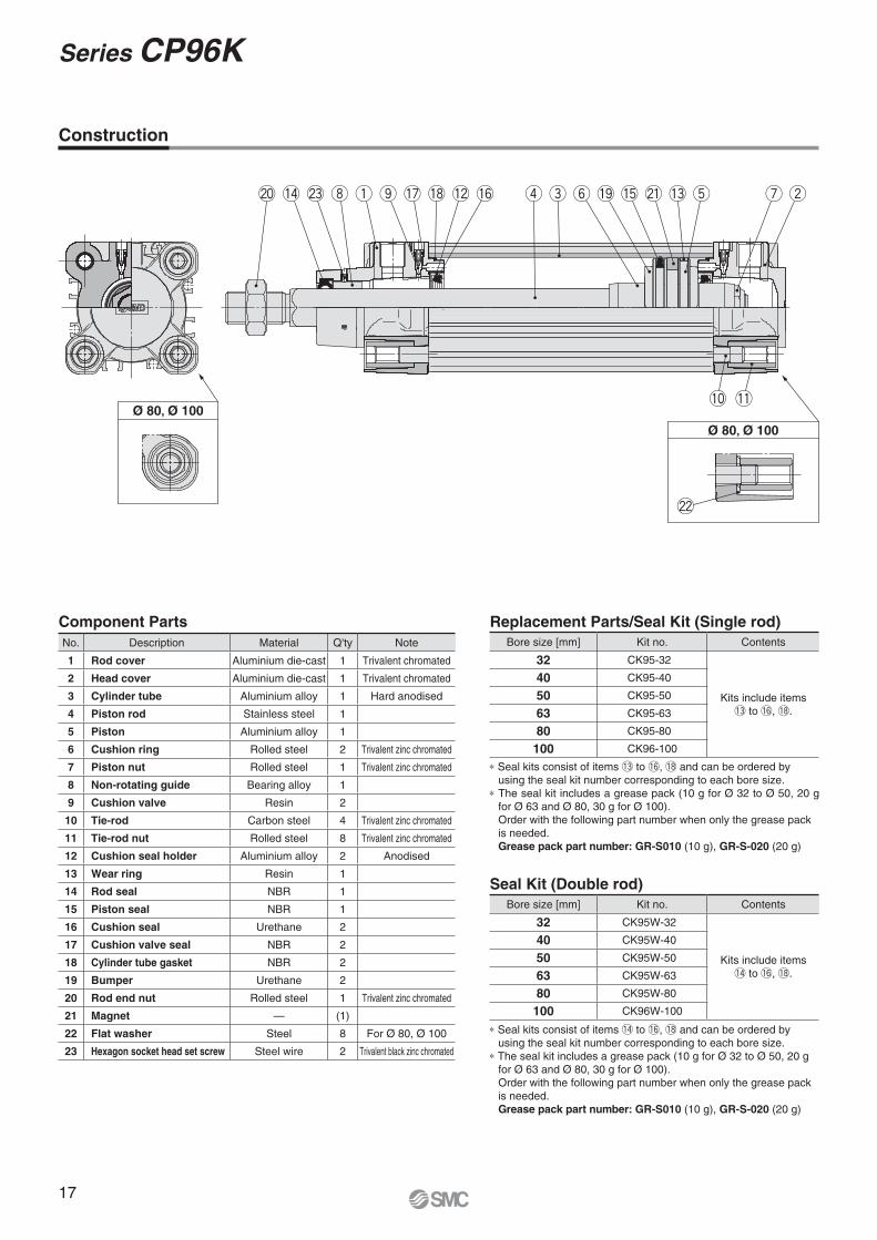
Ø 80, Ø 100
Ø 80, Ø 100
i q r e t u wy@0 !4 @3 o !7 !8 !2 !6 !9 !5 @1 !3
!0 !1
@2
Construction
Component Parts Replacement Parts/Seal Kit (Single rod)
Seal Kit (Double rod)
∗ Seal kits consist of items !3 to !6, !8 and can be ordered by
using the seal kit number corresponding to each bore size.
∗ The seal kit includes a grease pack (10 g for Ø 32 to Ø 50, 20 g
for Ø 63 and Ø 80, 30 g for Ø 100).
Order with the following part number when only the grease pack
is needed.
Grease pack part number: GR-S010 (10 g), GR-S-020 (20 g)
∗ Seal kits consist of items !4 to !6, !8 and can be ordered by
using the seal kit number corresponding to each bore size.
∗ The seal kit includes a grease pack (10 g for Ø 32 to Ø 50, 20 g
for Ø 63 and Ø 80, 30 g for Ø 100).
Order with the following part number when only the grease pack
is needed.
Grease pack part number: GR-S010 (10 g), GR-S-020 (20 g)
No. Description Material Q'ty Note
1 Rod cover Aluminium die-cast 1 Trivalent chromated
2 Head cover Aluminium die-cast 1 Trivalent chromated
3 Cylinder tube Aluminium alloy 1 Hard anodised
4 Piston rod Stainless steel 1
5 Piston Aluminium alloy 1
6 Cushion ring Rolled steel 2 Trivalent zinc chromated
7 Piston nut Rolled steel 1 Trivalent zinc chromated
8 Non-rotating guide Bearing alloy 1
9 Cushion valve Resin 2
10 Tie-rod Carbon steel 4 Trivalent zinc chromated
11 Tie-rod nut Rolled steel 8 Trivalent zinc chromated
12 Cushion seal holder Aluminium alloy 2 Anodised
13 Wear ring Resin 1
14 Rod seal NBR 1
15 Piston seal NBR 1
16 Cushion seal Urethane 2
17 Cushion valve seal NBR 2
18 Cylinder tube gasket NBR 2
19 Bumper Urethane 2
20 Rod end nut Rolled steel 1 Trivalent zinc chromated
21 Magnet — (1)
22 Flat washer Steel 8 For Ø 80, Ø 100
23 Hexagon socket head set screw Steel wire 2 Trivalent black zinc chromated
Bore size [mm] Kit no. Contents
32 CK95-32
Kits include items
!3 to !6, !8.
40 CK95-40
50 CK95-50
63 CK95-63
80 CK95-80
100 CK96-100
Bore size [mm] Kit no. Contents
32 CK95W-32
Kits include items
!4 to !6, !8.
40 CK95W-40
50 CK95W-50
63 CK95W-63
80 CK95W-80
100 CK96W-100
17
Series CP96K
Sectional view
A-A
Sectional view
A-A
Ø 32, Ø 40
Ø 32, Ø 40
Ø 80, Ø 100
Ø 80, Ø 100
A
A
A
A
ER
E
R
KK
ø B
D1
2 x EE
PLSL
PL 2 x EEport
Cushion valve
WBW
A PL
BG2 x 4 x RT
Width across flats SW
ø B
ø D
KK
ZY + 2 x Stroke
H + StrokeL8 + StrokeH
A WH G G WH + Stroke A
L2BG
VD
L12
2 x 4 x RT
L2 BG
L9
VD
E
R
REKK
ø B
D1
2 x EE
SLPL
BG2 x 4 x RT
PL 2 x EEport
Cushion valve
WBW
A PL
ø B
WA
WB
ZZ + Stroke
L8 + StrokeH
A WH G
L2 BG
L9
VD
VA
G
BG
L92 x 4 x RT
WA
WB
Ø 80, Ø 100
Ø 80, Ø 100
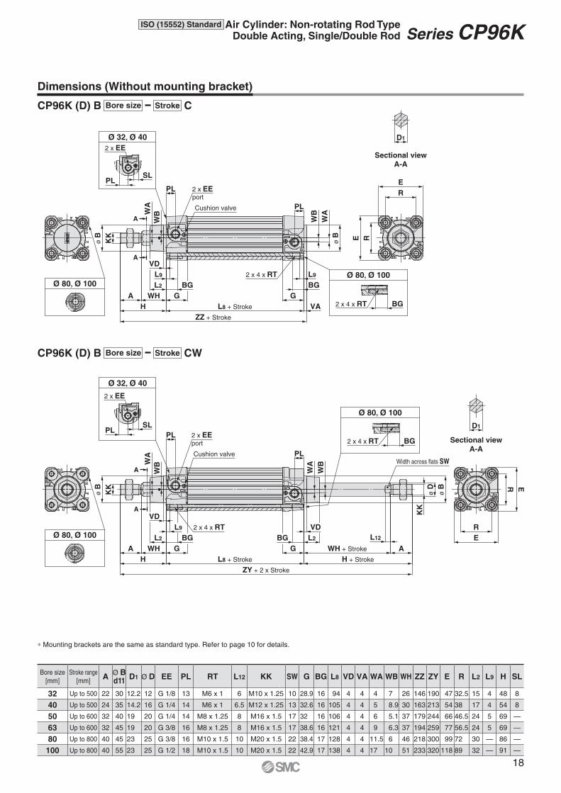
Dimensions (Without mounting bracket)
∗ Mounting brackets are the same as standard type. Refer to page 10 for details.
Bore size
[mm]
Stroke range
[mm]A
Ø Bd11
D1 Ø D EE PL RT L12 KK SW G BG L8 VD VA WA WB WH ZZ ZY E R L2 L9 H SL
32 Up to 500 22 30 12.2 12 G 1/8 13 M6 x 1 6 M10 x 1.25 10 28.9 16 94 4 4 4 7 26 146 190 47 32.5 15 4 48 8
40 Up to 500 24 35 14.2 16 G 1/4 14 M6 x 1 6.5 M12 x 1.25 13 32.6 16 105 4 4 5 8.9 30 163 213 54 38 17 4 54 8
50 Up to 600 32 40 19 20 G 1/4 14 M8 x 1.25 8 M16 x 1.5 17 32 16 106 4 4 6 5.1 37 179 244 66 46.5 24 5 69 —
63 Up to 600 32 45 19 20 G 3/8 16 M8 x 1.25 8 M16 x 1.5 17 38.6 16 121 4 4 9 6.3 37 194 259 77 56.5 24 5 69 —
80 Up to 800 40 45 23 25 G 3/8 16 M10 x 1.5 10 M20 x 1.5 22 38.4 17 128 4 4 11.5 6 46 218 300 99 72 30 — 86 —
100 Up to 800 40 55 23 25 G 1/2 18 M10 x 1.5 10 M20 x 1.5 22 42.9 17 138 4 4 17 10 51 233 320 118 89 32 — 91 —
CP96K (D) B
CP96K (D) B
C
CW
Bore size
Bore size
Stroke
Stroke
18
ISO (15552) Standard Air Cylinder: Non-rotating Rod TypeDouble Acting, Single/Double Rod Series CP96K
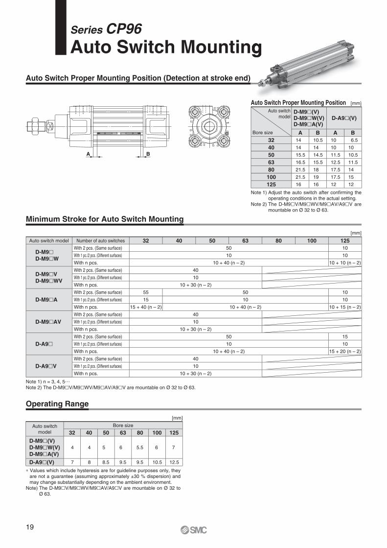
Auto switch model Number of auto switches 32 40 50 63 80 100 125
D-M9�D-M9�W
With 2 pcs. (Same surface) 50 10
With 1 pc./2 pcs. (Different surfaces) 10 10
With n pcs. 10 + 40 (n – 2) 10 + 10 (n – 2)
D-M9�V
D-M9�WV
With 2 pcs. (Same surface) 40
With 1 pc./2 pcs. (Different surfaces) 10
With n pcs. 10 + 30 (n – 2)
D-M9�A
With 2 pcs. (Same surface) 55 50 10
With 1 pc./2 pcs. (Different surfaces) 15 10 10
With n pcs. 15 + 40 (n – 2) 10 + 40 (n – 2) 10 + 15 (n – 2)
D-M9�AV
With 2 pcs. (Same surface) 40
With 1 pc./2 pcs. (Different surfaces) 10
With n pcs. 10 + 30 (n – 2)
D-A9�With 2 pcs. (Same surface) 50 15
With 1 pc./2 pcs. (Different surfaces) 10 10
With n pcs. 10 + 40 (n – 2) 15 + 20 (n – 2)
D-A9�V
With 2 pcs. (Same surface) 40
With 1 pc./2 pcs. (Different surfaces) 10
With n pcs. 10 + 30 (n – 2)
Auto switch
model
Bore size
32 40 50 63 80 100 125
D-M9�(V)
D-M9�W(V)
D-M9�A(V)
4 4 5 6 5.5 6 7
D-A9�(V) 7 8 8.5 9.5 9.5 10.5 12.5
Auto switch
model
Bore size
D-M9�(V)D-M9�W(V)D-M9�A(V)
D-A9�(V)
A B A B
32 14 10.5 10 6.5
40 14 14 10 10
50 15.5 14.5 11.5 10.5
63 16.5 15.5 12.5 11.5
80 21.5 18 17.5 14
100 21.5 19 17.5 15
125 16 16 12 12
A B
Note 1) n = 3, 4, 5…
Note 2) The D-M9�V/M9�WV/M9�AV/A9�V are mountable on Ø 32 to Ø 63.
[mm]
[mm]
[mm]
Auto Switch Proper Mounting Position
Note 1) Adjust the auto switch after confi rming the
operating conditions in the actual setting.
Note 2) The D-M9�V/M9�WV/M9�AV/A9�V are
mountable on Ø 32 to Ø 63.
∗ Values which include hysteresis are for guideline purposes only, they
are not a guarantee (assuming approximately ±30 % dispersion) and
may change substantially depending on the ambient environment.
Note) The D-M9�V/M9�WV/M9�AV/A9�V are mountable on Ø 32 to
Ø 63.
Minimum Stroke for Auto Switch Mounting
Auto Switch Proper Mounting Position (Detection at stroke end)
Operating Range
Series CP96
Auto Switch Mounting
[ ]Auto Switch Proper Mounting Position
19
Auto switch mounting screw
Auto switch
Auto switch model Tightening torque
D-M9�(V)
D-M9�W(V)
D-M9�A(V)
0.05 to 0.15
D-A9�(V) 0.10 to 0.20
Type Model Electrical entry Features Applicable bore size
Solid state
D-M9NV, M9PV, M9BV
Grommet (Perpendicular)
—
Ø 32 to Ø 63
D-M9NWV, M9PWV, M9BWVDiagnostic indication
(2-colour indication)
D-M9NAV, M9PAV, M9BAVWater resistant
(2-colour indication)
ReedD-A93V, A96V —
D-A90V Without indicator light
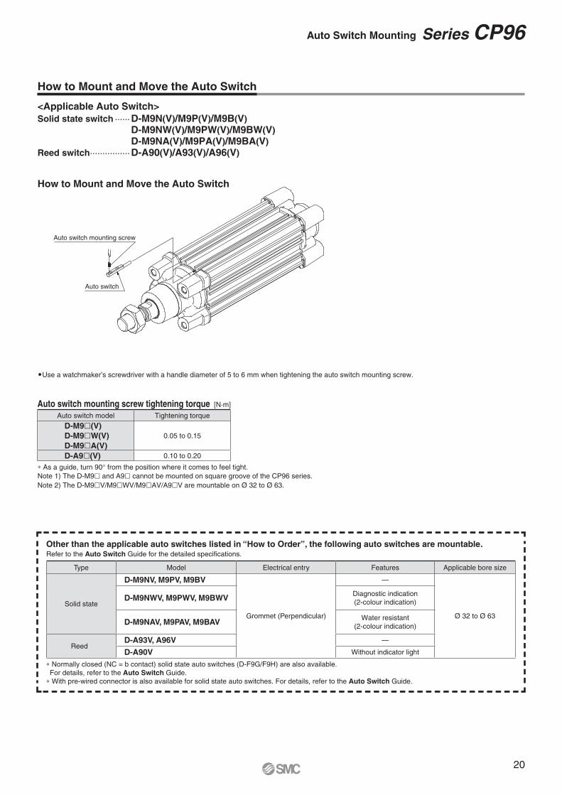
<Applicable Auto Switch>
Solid state switch ······ D-M9N(V)/M9P(V)/M9B(V)
D-M9NW(V)/M9PW(V)/M9BW(V)
D-M9NA(V)/M9PA(V)/M9BA(V)
Reed switch ················ D-A90(V)/A93(V)/A96(V)
How to Mount and Move the Auto Switch
Auto switch mounting screw tightening torque [N·m]
∗ As a guide, turn 90° from the position where it comes to feel tight.
Note 1) The D-M9� and A9� cannot be mounted on square groove of the CP96 series.
Note 2) The D-M9�V/M9�WV/M9�AV/A9�V are mountable on Ø 32 to Ø 63.
�Use a watchmaker’s screwdriver with a handle diameter of 5 to 6 mm when tightening the auto switch mounting screw.
How to Mount and Move the Auto Switch
∗ Normally closed (NC = b contact) solid state auto switches (D-F9G/F9H) are also available.
For details, refer to the Auto Switch Guide.
∗ With pre-wired connector is also available for solid state auto switches. For details, refer to the Auto Switch Guide.
Other than the applicable auto switches listed in “How to Order”, the following auto switches are mountable.Refer to the Auto Switch Guide for the detailed specifi cations.
20
Auto Switch Mounting Series CP96
COM
Input
Blue
Black
Brown
Auto switch
(PLC internal circuit)
COM
Input
Blue
Brown
Auto switch
(PLC internal circuit)
COM
Input
Blue
Black
Brown
Auto switch
(PLC internal circuit)
Input
COM
Blue
Brown
Auto switch
(PLC internal circuit)
RelayLoad
Blue
Black
Brown
Auto switch 2
Blue
Black
Brown
Auto switch 1Load
Blue
Black
Brown
Auto switch 2
Blue
Black
Brown
Auto switch 1
Relay
LoadBlue
Black
Brown
Auto switch 2
Blue
Black
Brown
Auto switch 1
Load
Blue
Black
Brown
Auto switch 2
Blue
Black
Brown
Auto switch 1
Load
Blue
Brown
Auto switch 2
Blue
Brown
Auto switch 1
Load
Blue
Black
Brown
Auto switch 2
Blue
Black
Brown
Auto switch 1
Load
Blue
Black
Brown
Auto switch 2
Blue
Black
Brown
Auto switch 1
Load
Blue
Brown
Auto switch 2
Blue
Brown
Auto switch 1
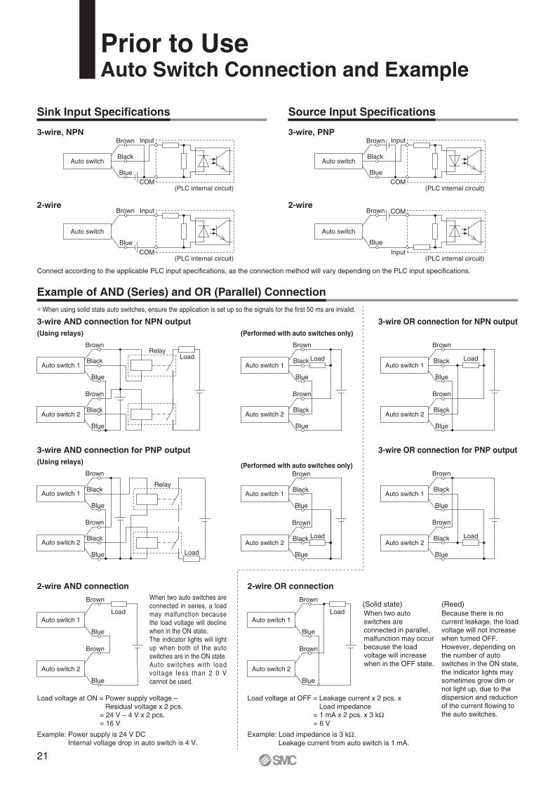
∗ When using solid state auto switches, ensure the application is set up so the signals for the fi rst 50 ms are invalid.
Connect according to the applicable PLC input specifi cations, as the connection method will vary depending on the PLC input specifi cations.
Because there is no
current leakage, the load
voltage will not increase
when turned OFF.
However, depending on
the number of auto
switches in the ON state,
the indicator lights may
sometimes grow dim or
not light up, due to the
dispersion and reduction
of the current fl owing to
the auto switches.
When two auto
switches are
connected in parallel,
malfunction may occur
because the load
voltage will increase
when in the OFF state.Auto switches with load
voltage less than 2 0 V
cannot be used.
When two auto switches are
connected in series, a load
may malfunction because
the load voltage will decline
when in the ON state.
The indicator lights will light
up when both of the auto
switches are in the ON state.
(Reed)(Solid state)
Example: Load impedance is 3 kΩ.
Leakage current from auto switch is 1 mA.
Load voltage at OFF = Leakage current x 2 pcs. x
Load impedance= 1 mA x 2 pcs. x 3 kΩ= 6 V
Example: Power supply is 24 V DC
Internal voltage drop in auto switch is 4 V.
Load voltage at ON = Power supply voltage –
Residual voltage x 2 pcs.
= 24 V − 4 V x 2 pcs.
= 16 V
Prior to UseAuto Switch Connection and Example
3-wire, NPN
2-wire
3-wire, PNP
2-wire
3-wire AND connection for NPN output
(Using relays) (Performed with auto switches only)
3-wire OR connection for NPN output
3-wire AND connection for PNP output
(Using relays)(Performed with auto switches only)
3-wire OR connection for PNP output
2-wire AND connection 2-wire OR connection
Sink Input Specifi cations
Example of AND (Series) and OR (Parallel) Connection
Source Input Specifi cations
21
Series CP96
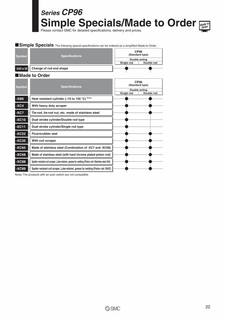
Simple Specials/Made to OrderPlease contact SMC for detailed specifi cations, delivery and prices.
� Made to Order
� Simple Specials The following special specifi cations can be ordered as a simplifi ed Made-to-Order.
Heat resistant cylinder (–10 to 150 °C) Note)
With heavy duty scraper
Tie-rod, tie-rod nut, etc. made of stainless steel
Dual stroke cylinder/Double rod type
Dual stroke cylinder/Single rod type
Fluororubber seal
With coil scraper
Made of stainless steel (Combination of -XC7 and -XC68)
Made of stainless steel (with hard chrome plated piston rod)
Spatter resistant coil scraper, Lube-retainer, grease for welding (Piston rod: Stainless steel 304)
Spatter resistant coil scraper, Lube-retainer, grease for welding (Piston rod: S45C)
-XB6
-XC4
-XC7
-XC10
-XC11
-XC22
-XC35
-XC65
-XC68
-XC88
-XC89
Symbol Specifi cations
Symbol Specifi cations
Change of rod end shape-XA0 to 30
CP96(Standard type)
Double acting
Single rod Double rod
CP96(Standard type)
Double acting
Single rod Double rod
Note) The products with an auto switch are not compatible.
22
Applicable Series
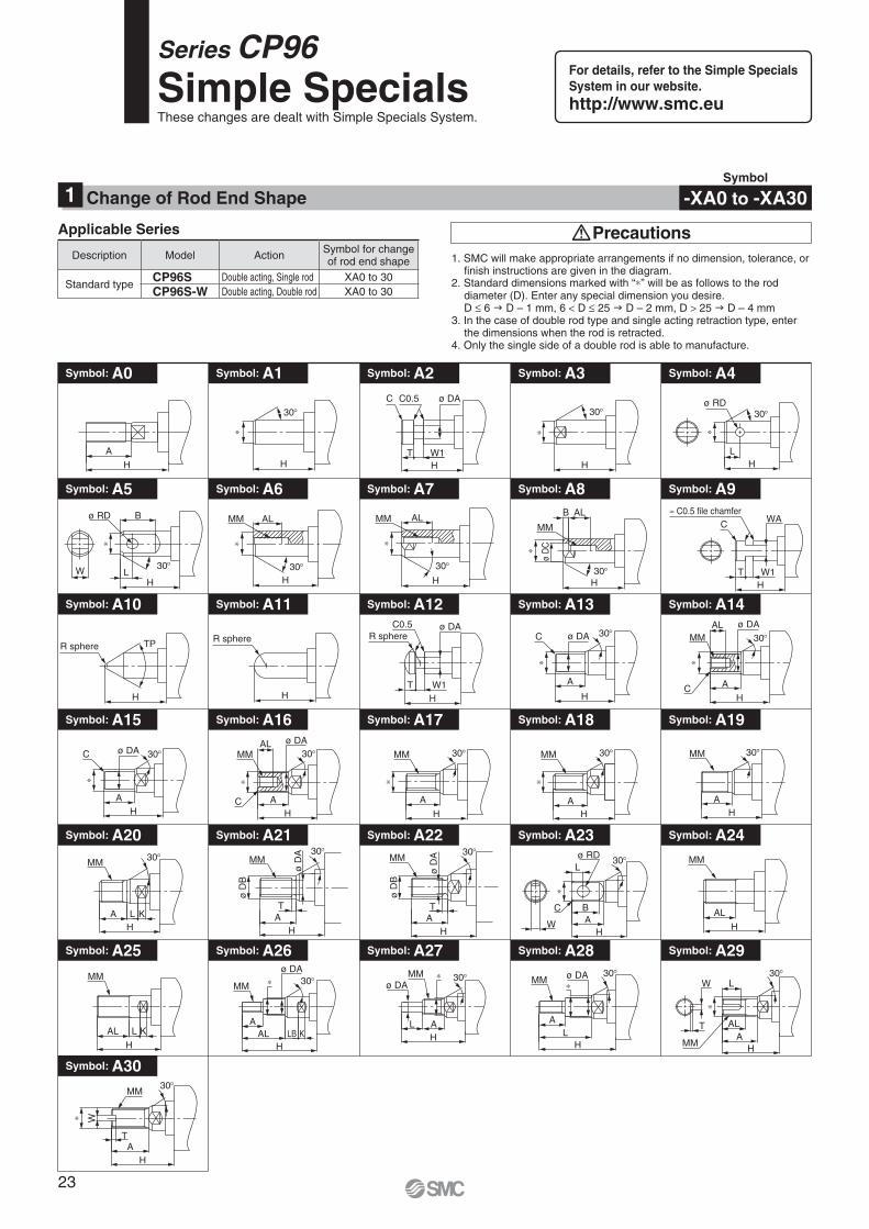
1. SMC will make appropriate arrangements if no dimension, tolerance, or fi nish instructions are given in the diagram.
2. Standard dimensions marked with “∗” will be as follows to the rod diameter (D). Enter any special dimension you desire.D ≤ 6 D – 1 mm, 6 < D ≤ 25 D – 2 mm, D > 25 D – 4 mm
3. In the case of double rod type and single acting retraction type, enter the dimensions when the rod is retracted.
4. Only the single side of a double rod is able to manufacture.
Precautions
Symbol
-XA0 to -XA30Change of Rod End Shape1
Series CP96
Simple SpecialsThese changes are dealt with Simple Specials System.
Symbol: A0 Symbol: A1 Symbol: A2 Symbol: A3
Symbol: A15 Symbol: A16 Symbol: A17 Symbol: A18 Symbol: A19
Symbol: A28 Symbol: A29
Symbol: A30
Symbol: A24
Symbol: A25 Symbol: A26 Symbol: A27
Symbol: A20 Symbol: A21 Symbol: A22 Symbol: A23
Symbol: A8 Symbol: A9
Symbol: A10 Symbol: A11
Symbol: A4
Symbol: A5 Symbol: A6 Symbol: A7
Symbol: A12 Symbol: A13 Symbol: A14
A
H H HW1
C ø DAC0.5
T
30°
∗
H
30°
∗
HL
30°ø RD
∗
HW1T
WAC
≈ C0.5 file chamfer
H
ALB
MM
30°
ø D
C∗
LW
ø RD B
H
30°
∗
ALMM
H30°
∗
ALMM
H
30°
∗
H
TPR sphere
H
R sphere
HT W1
ø DAC0.5R sphere
ø DA
A
HC
ALMM 30°
∗
ø DA
A
C
H
30°
∗
H
A
MM 30°
∗
HA
MM 30°
∗
HA
MM 30°
H
ø DA
AC
ALMM 30°
∗
ø DA
AH
C 30°
∗
A L KH
MM 30°
AL
H
MM
W
C BA
H
Lø RD
∗
30°MM30°
ø D
B
HAT
ø D
A
MM
H
ø D
A 30°
T A
ø D
B
AL L K
H
MM
ALH
LB KA
MM
ø DA∗ 30° MM
AL
H
ø DA∗
30°
MM
ALA
H
LW
T
∗
30°
L AH
MMø DA
∗ 30°
MM
AT
H
∗ W
30°
Description Model ActionSymbol for changeof rod end shape
Standard typeCP96S Double acting, Single rod XA0 to 30
CP96S-W Double acting, Double rod XA0 to 30
For details, refer to the Simple Specials
System in our website.
http://www.smc.eu
23
Applicable Series
XB6
Heat resistant cylinder
Standard model no.
How to Order
Specifications
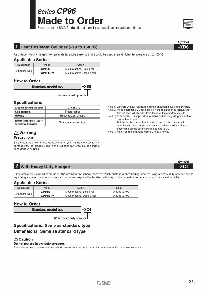
PrecautionsWarning
Note 1) Operate without lubrication from a pneumatic system lubricator.Note 2) Please contact SMC for details on the maintenance intervals for
this cylinder, which differ from those of the standard cylinder.Note 3) In principle, it is impossible to make built-in magnet type and the
one with auto switch.But, as for the one with auto switch, and the heat resistant cylinder with heat resistant auto switch, since it will be differed depending on the series, please contact SMC.
Note 4) Piston speed is ranged from 50 to 500 mm/s.
Symbol
-XB6Heat Resistant Cylinder (–10 to 150 °C)1
Air cylinder which changed the seal material and grease, so that it could be used even at higher temperature up to 150 °C.
Series CP96Made to OrderPlease contact SMC for detailed dimensions, specifications and lead times.
Be aware that smoking cigarettes etc. after your hands have come into contact with the grease used in this cylinder can create a gas that is hazardous to humans.
Description Model Action
Standard typeCP96S Double acting, Single rod
CP96S-W Double acting, Double rod
Ambient temperature range –10 to 150 °CSeal material Fluororubber
Grease Heat resistant grease
Specifications other than above and external dimensions
Same as standard type
Symbol
-XC4With Heavy Duty Scraper2
Do not replace heavy duty scrapers.Since heavy duty scrapers are press-fit, do not replace the cover only, but rather the entire rod cover assembly.
Applicable Series
XC4
With heavy duty scraper
Standard model no.
How to Order
Specifications: Same as standard typeDimensions: Same as standard type
Caution
It is suitable for using cylinders under the environment, where there are much dusts in a surrounding area by using a heavy duty scraper on the wiper ring, or using cylinders under earth and sand exposed to the die-casted equipment, construction machinery, or industrial vehicles.
Description Model Action Nota
Standard typeCP96S Double acting, Single rod Ø 32 to Ø 100
CP96S-W Double acting, Double rod Ø 32 to Ø 100
24
Stroke A Stroke B
ZZ + Stroke (A + B)
L8 + Stroke (A + B)
NA
GC
NB
Applicable Series
XC7
Tie-rod, tie-rod nut, etc. made of
stainless steel
Standard model no.
How to Order Specifi cations
Symbol
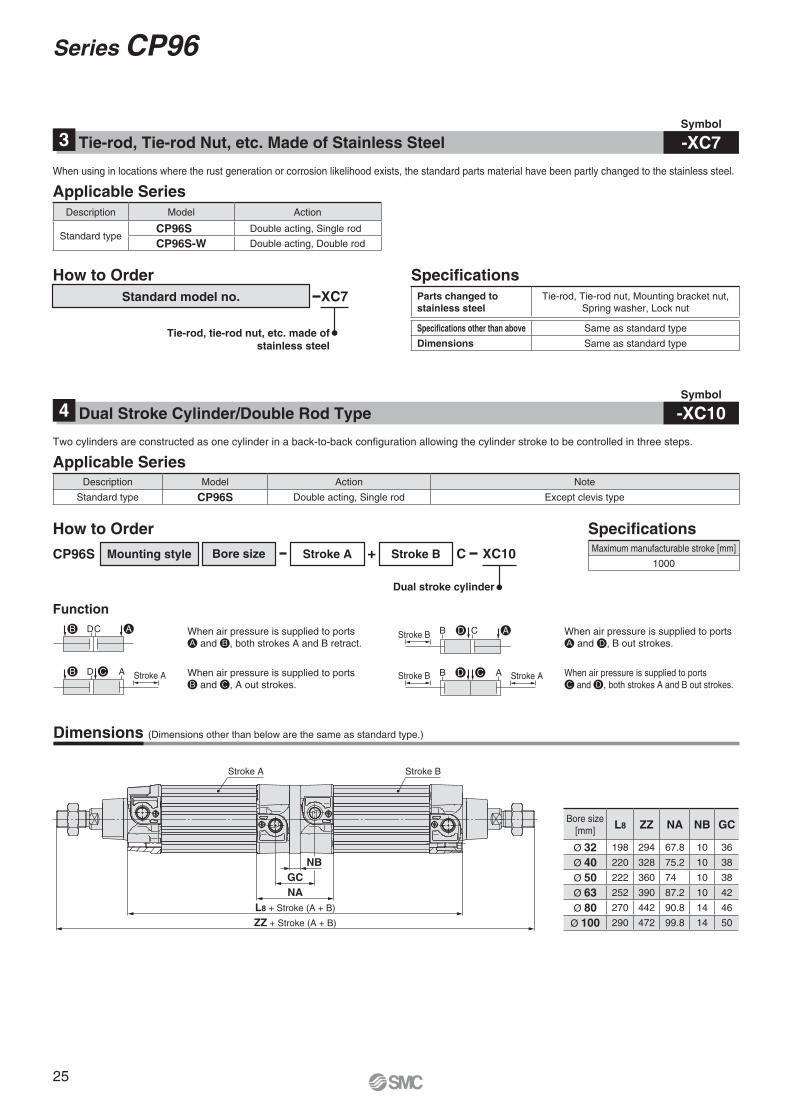
-XC7Tie-rod, Tie-rod Nut, etc. Made of Stainless Steel3
When using in locations where the rust generation or corrosion likelihood exists, the standard parts material have been partly changed to the stainless steel.
Description Model Action
Standard typeCP96S Double acting, Single rod
CP96S-W Double acting, Double rod
Parts changed to
stainless steel
Tie-rod, Tie-rod nut, Mounting bracket nut,
Spring washer, Lock nut
Specifications other than above Same as standard type
Dimensions Same as standard type
Applicable Series
CP96S Mounting style Bore size Stroke A + Stroke B XC10C
How to Order
Dual stroke cylinder
Function
Specifi cations
Dimensions (Dimensions other than below are the same as standard type.)
Symbol
-XC10Dual Stroke Cylinder/Double Rod Type4
Two cylinders are constructed as one cylinder in a back-to-back confi guration allowing the cylinder stroke to be controlled in three steps.
Stroke AStroke BStroke A
Stroke BWhen air pressure is supplied to ports and , both strokes A and B retract.
When air pressure is supplied to ports and , B out strokes.
When air pressure is supplied to ports and , both strokes A and B out strokes.
When air pressure is supplied to ports and , A out strokes.
D CB C
B A D A
ABAD
CD CB
Description Model Action Note
Standard type CP96S Double acting, Single rod Except clevis type
Maximum manufacturable stroke [mm]
1000
Bore size
[mm]L8 ZZ NA NB GC
Ø 32 198 294 67.8 10 36
Ø 40 220 328 75.2 10 38
Ø 50 222 360 74 10 38
Ø 63 252 390 87.2 10 42
Ø 80 270 442 90.8 14 46
Ø 100 290 472 99.8 14 50
25
Series CP96
Stroke B Stroke A
ZZ + Stroke (A + B)
L8 + Stroke (A + B)
NA
GC
NB
ACB
Stroke B Stroke A
A
AC
AC
Stroke B Stroke A
CB
Stroke A
B
BStroke B-A
ACB
Stroke B Stroke A
ACB
Stroke B Stroke A
ACBStroke A
CB AStroke B
ACB
Stroke B Stroke A
ACB
W
Stroke A
W
Applicable Series
Function
Precautions
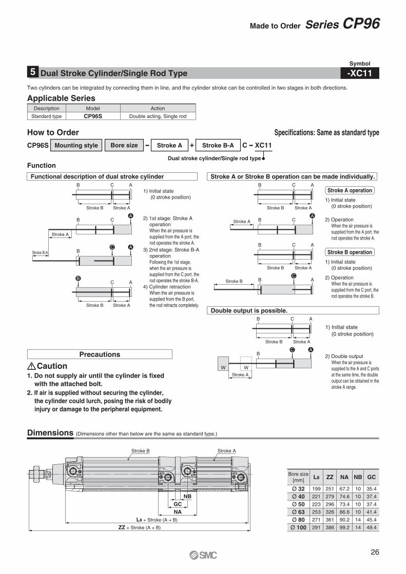
1. Do not supply air until the cylinder is fi xed
with the attached bolt.
2. If air is supplied without securing the cylinder,
the cylinder could lurch, posing the risk of bodily
injury or damage to the peripheral equipment.
Caution
Specifi cations: Same as standard type
Symbol
-XC11Dual Stroke Cylinder/Single Rod Type5
Two cylinders can be integrated by connecting them in line, and the cylinder stroke can be controlled in two stages in both directions.
CP96S Mounting style Bore size Stroke A Stroke B-A XC11C
How to Order
+
Dual stroke cylinder/Single rod type
1) Initial state
(0 stroke position)
2) 1st stage: Stroke A
operation
When the air pressure is
supplied from the A port, the
rod operates the stroke A.
1) Initial state
(0 stroke position)
2) Operation
When the air pressure is
supplied from the A port, the
rod operates the stroke A.
1) Initial state
(0 stroke position)
2) Double output
When the air pressure is
supplied to the A and C ports
at the same time, the double
output can be obtained in the
stroke A range.
3) 2nd stage: Stroke B-A
operation
Following the 1st stage,
when the air pressure is
supplied from the C port, the
rod operates the stroke B-A.
4) Cylinder retraction
When the air pressure is
supplied from the B port,
the rod retracts completely.
Stroke A or Stroke B operation can be made individually.
Double output is possible.
Functional description of dual stroke cylinder
Stroke A operation
1) Initial state
(0 stroke position)
2) Operation
When the air pressure is
supplied from the C port, the
rod operates the stroke B.
Stroke B operation
Description Model Action
Standard type CP96S Double acting, Single rod
Dimensions (Dimensions other than below are the same as standard type.)
Bore size
[mm]L8 ZZ NA NB GC
Ø 32 199 251 67.2 10 35.4
Ø 40 221 279 74.6 10 37.4
Ø 50 223 296 73.4 10 37.4
Ø 63 253 326 86.6 10 41.4
Ø 80 271 361 90.2 14 45.4
Ø 100 291 386 99.2 14 49.4
26
Made to Order Series CP96
Applicable Series
XC22
Fluororubber seal
(including bumper)
Standard model no.
How to Order
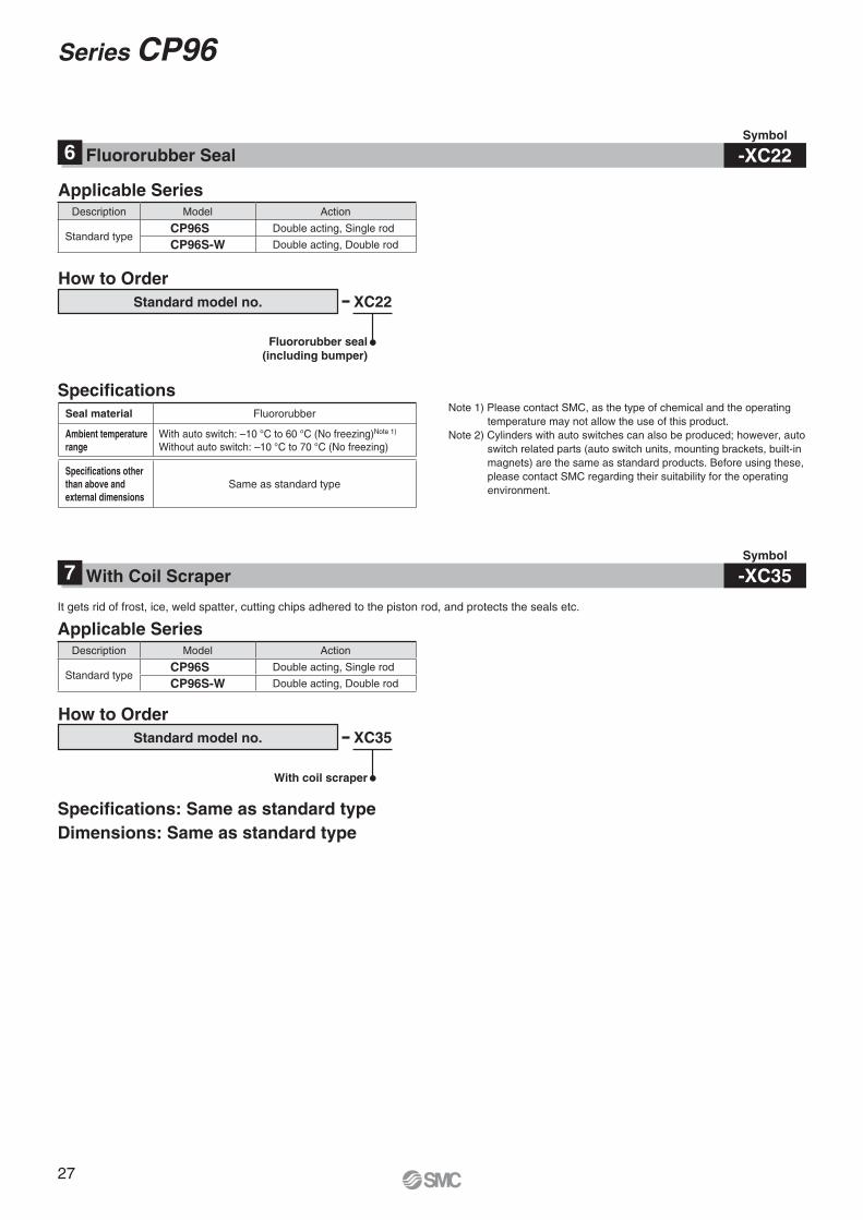
Specifi cationsNote 1) Please contact SMC, as the type of chemical and the operating
temperature may not allow the use of this product.
Note 2) Cylinders with auto switches can also be produced; however, auto
switch related parts (auto switch units, mounting brackets, built-in
magnets) are the same as standard products. Before using these,
please contact SMC regarding their suitability for the operating
environment.
Symbol
-XC22Fluororubber Seal6
Description Model Action
Standard typeCP96S Double acting, Single rod
CP96S-W Double acting, Double rod
Seal material Fluororubber
Ambient temperature
range
With auto switch: –10 °C to 60 °C (No freezing)Note 1)
Without auto switch: –10 °C to 70 °C (No freezing)
Specifications other
than above and
external dimensions
Same as standard type
Applicable Series
XC35
With coil scraper
Standard model no.
How to Order
Specifi cations: Same as standard type
Dimensions: Same as standard type
Symbol
-XC35With Coil Scraper7
It gets rid of frost, ice, weld spatter, cutting chips adhered to the piston rod, and protects the seals etc.
Description Model Action
Standard typeCP96S Double acting, Single rod
CP96S-W Double acting, Double rod
27
Series CP96
Applicable Series
XC68
Made of stainless steel
(With hard chrome plated piston rod)
Standard model no.
How to Order
Maximum Stroke
Specifi cations
Symbol
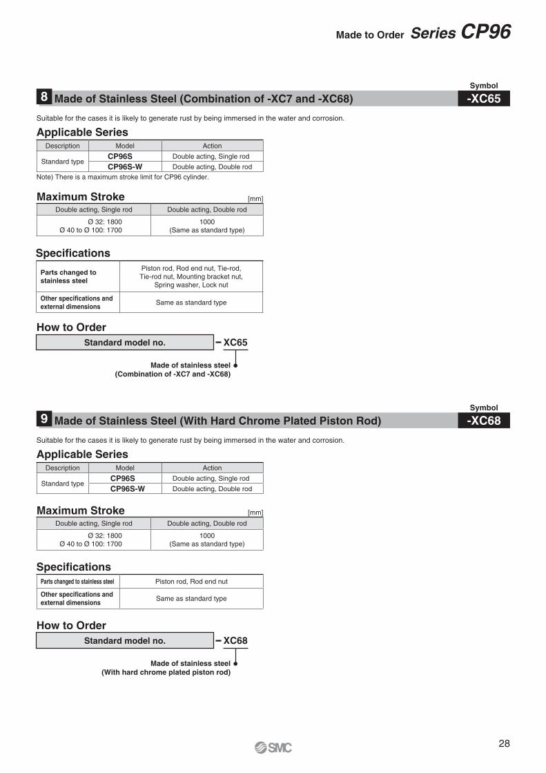
-XC68Made of Stainless Steel (With Hard Chrome Plated Piston Rod)9
Suitable for the cases it is likely to generate rust by being immersed in the water and corrosion.
Description Model Action
Standard typeCP96S Double acting, Single rod
CP96S-W Double acting, Double rod
Double acting, Single rod Double acting, Double rod
Ø 32: 1800
Ø 40 to Ø 100: 1700
1000
(Same as standard type)
Parts changed to stainless steel Piston rod, Rod end nut
Other specifications and
external dimensionsSame as standard type
Applicable Series
Note) There is a maximum stroke limit for CP96 cylinder.
XC65
Made of stainless steel
(Combination of -XC7 and -XC68)
Standard model no.
How to Order
Maximum Stroke
Specifi cations
Symbol
-XC65Made of Stainless Steel (Combination of -XC7 and -XC68)8
Suitable for the cases it is likely to generate rust by being immersed in the water and corrosion.
Description Model Action
Standard typeCP96S Double acting, Single rod
CP96S-W Double acting, Double rod
Double acting, Single rod Double acting, Double rod
Ø 32: 1800
Ø 40 to Ø 100: 1700
1000
(Same as standard type)
Parts changed to
stainless steel
Piston rod, Rod end nut, Tie-rod,
Tie-rod nut, Mounting bracket nut,
Spring washer, Lock nut
Other specifications and
external dimensionsSame as standard type
[mm]
[mm]
28
Made to Order Series CP96
Specifi cations
Specifi cations
Symbol
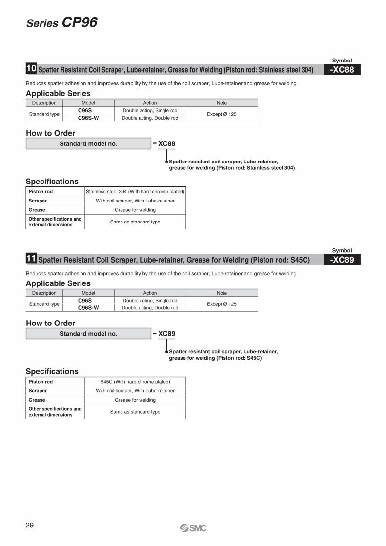
-XC89Spatter Resistant Coil Scraper, Lube-retainer, Grease for Welding (Piston rod: S45C)11
Applicable Series
Applicable Series
XC88
XC89
Spatter resistant coil scraper, Lube-retainer,
grease for welding (Piston rod: Stainless steel 304)
Spatter resistant coil scraper, Lube-retainer,
grease for welding (Piston rod: S45C)
Standard model no.
Standard model no.
How to Order
How to Order
Symbol
-XC88Spatter Resistant Coil Scraper, Lube-retainer, Grease for Welding (Piston rod: Stainless steel 304)10
Reduces spatter adhesion and improves durability by the use of the coil scraper, Lube-retainer and grease for welding.
Reduces spatter adhesion and improves durability by the use of the coil scraper, Lube-retainer and grease for welding.
Piston rod Stainless steel 304 (With hard chrome plated)
Scraper With coil scraper, With Lube-retainer
Grease Grease for welding
Other specifications and
external dimensionsSame as standard type
Piston rod S45C (With hard chrome plated)
Scraper With coil scraper, With Lube-retainer
Grease Grease for welding
Other specifications and
external dimensionsSame as standard type
Description Model Action Note
Standard typeC96S Double acting, Single rod
Except Ø 125C96S-W Double acting, Double rod
Description Model Action Note
Standard typeC96S Double acting, Single rod
Except Ø 125C96S-W Double acting, Double rod
29
Series CP96
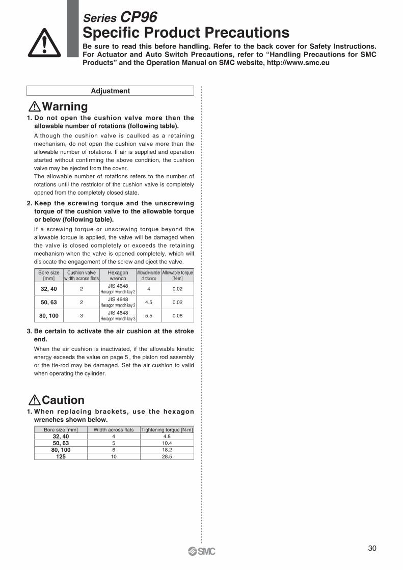
1. Do not open the cushion valve more than the
allowable number of rotations (following table).
Although the cushion valve is caulked as a retaining
mechanism, do not open the cushion valve more than the
allowable number of rotations. If air is supplied and operation
started without confirming the above condition, the cushion
valve may be ejected from the cover.
The allowable number of rotations refers to the number of
rotations until the restrictor of the cushion valve is completely
opened from the completely closed state.
2. Keep the screwing torque and the unscrewing
torque of the cushion valve to the allowable torque
or below (following table).
If a screwing torque or unscrewing torque beyond the
allowable torque is applied, the valve will be damaged when
the valve is closed completely or exceeds the retaining
mechanism when the valve is opened completely, which will
dislocate the engagement of the screw and eject the valve.
Bore size[mm]
Cushion valve width across fl ats
Hexagon wrench
Allowable number of rotations
Allowable torque[N·m]
32, 40 2JIS 4648
Hexagon wrench key 24 0.02
50, 63 2JIS 4648
Hexagon wrench key 24.5 0.02
80, 100 3JIS 4648
Hexagon wrench key 35.5 0.06
3. Be certain to activate the air cushion at the stroke
end.
When the air cushion is inactivated, if the allowable kinetic
energy exceeds the value on page 5 , the piston rod assembly
or the tie-rod may be damaged. Set the air cushion to valid
when operating the cylinder.
1. When replacing brackets, use the hexagon
wrenches shown below.
Bore size [mm] Width across fl ats Tightening torque [N·m]
32, 40 4 4.8
50, 63 5 10.4
80, 100 6 18.2
125 10 28.5
Warning
Caution
Adjustment
Series CP96Specifi c Product PrecautionsBe sure to read this before handling. Refer to the back cover for Safety Instructions. For Actuator and Auto Switch Precautions, refer to “Handling Precautions for SMC Products” and the Operation Manual on SMC website, http://www.smc.eu
30

Lithuania +370 5 2308118 www.smclt.lt [email protected] +31 (0)205318888 www.smcpneumatics.nl [email protected] +47 67129020 www.smc-norge.no [email protected] +48 222119600 www.smc.pl [email protected] +351 226166570 www.smc.eu [email protected] +40 213205111 www.smcromania.ro [email protected] +7 8127185445 www.smc-pneumatik.ru [email protected] +421 (0)413213212 www.smc.sk [email protected] +386 (0)73885412 www.smc.si [email protected] +34 902184100 www.smc.eu [email protected] +46 (0)86031200 www.smc.nu [email protected] +41 (0)523963131 www.smc.ch [email protected] +90 212 489 0 440 www.smcpnomatik.com.tr [email protected] UK +44 (0)845 121 5122 www.smcpneumatics.co.uk [email protected]
Specifications are subject to change without prior notice and any obligation on the part of the manufacturer.SMC CORPORATION Akihabara UDX 15F, 4-14-1, Sotokanda, Chiyoda-ku, Tokyo 101-0021, JAPAN Phone: 03-5207-8249 FAX: 03-5298-5362
1st printing WQ printing WP 00 Printed in Spain
Austria +43 (0)2262622800 www.smc.at [email protected] +32 (0)33551464 www.smcpneumatics.be [email protected] +359 (0)2807670 www.smc.bg [email protected] Croatia +385 (0)13707288 www.smc.hr [email protected] Republic +420 541424611 www.smc.cz [email protected] Denmark +45 70252900 www.smcdk.com [email protected] Estonia +372 6510370 www.smcpneumatics.ee [email protected] +358 207513513 www.smc.fi [email protected] +33 (0)164761000 www.smc-france.fr [email protected] +49 (0)61034020 www.smc.de [email protected] +30 210 2717265 www.smchellas.gr [email protected] +36 23513000 www.smc.hu [email protected] +353 (0)14039000 www.smcpneumatics.ie [email protected] +39 0292711 www.smcitalia.it [email protected] +371 67817700 www.smclv.lv [email protected]
Safety Instructions Be sure to read “Handling Precautions for SMC Products” (M-E03-3) before using.
SMC Corporation (Europe)
1. The compatibility of the product is the responsibility of the person
who designs the equipment or decides its specifications. Since the product specified here is used under various operating conditions, its
compatibility with specific equipment must be decided by the person who designs the equipment or decides its specifications based on necessary analysis and test results. The expected performance and safety assurance of the equipment will be the responsibility of the person who has determined its compatibility with the product. This person should also continuously review all specifications of the product referring to its latest catalogue information, with a view to giving due consideration to any possibility of equipment failure when configuring the equipment.
2. Only personnel with appropriate training should operate machinery
and equipment. The product specified here may become unsafe if handled incorrectly. The assembly,
operation and maintenance of machines or equipment including our products must be performed by an operator who is appropriately trained and experienced.
3. . Do not service or attempt to remove product and
machinery/equipment until safety is confirmed.1. The inspection and maintenance of machinery/equipment should only be performed
after measures to prevent falling or runaway of the driven objects have been confirmed.
2. When the product is to be removed, confirm that the safety measures as mentioned above are implemented and the power from any appropriate source is cut, and read and understand the specific product precautions of all relevant products carefully.
3. Before machinery/equipment is restarted, take measures to prevent unexpected operation and malfunction.
4. Contact SMC beforehand and take special consideration of safety
measures if the product is to be used in any of the following
conditions. 1. Conditions and environments outside of the given specifications, or use outdoors or in
a place exposed to direct sunlight.2. Installation on equipment in conjunction with atomic energy, railways, air navigation,
space, shipping, vehicles, military, medical treatment, combustion and recreation, or equipment in contact with food and beverages, emergency stop circuits, clutch and brake circuits in press applications, safety equipment or other applications unsuitable for the standard specifications described in the product catalogue.
3. An application which could have negative effects on people, property, or animals requiring special safety analysis.
4. Use in an interlock circuit, which requires the provision of double interlock for possible failure by using a mechanical protective function, and periodical checks to confirm proper operation.
Warning Limited warranty and Disclaimer/Compliance Requirements The product used is subject to the following “Limited warranty and Disclaimer” and “Compliance Requirements”.Read and accept them before using the product.
1. The product is provided for use in manufacturing industries.The product herein described is basically provided for peaceful use in manufacturing industries. If considering using the product in other industries, consult SMC beforehand and exchange specifications or a contract if necessary. If anything is unclear, contact your nearest sales branch.
CautionSMC products are not intended for use as instruments for legal
metrology.Measurement instruments that SMC manufactures or sells have not been qualified by type approval tests relevant to the metrology (measurement) laws of each country.Therefore, SMC products cannot be used for business or certification ordained by the metrology (measurement) laws of each country.
Caution
Limited warranty and Disclaimer
1. The warranty period of the product is 1 year in service or 1.5 years after the product is delivered, wichever is first.∗2)
Also, the product may have specified durability, running distance or replacement parts. Please consult your nearest sales branch.
2. For any failure or damage reported within the warranty period which is clearly our responsibility, a replacement product or necessary parts will be provided. This limited warranty applies only to our product independently, and not to any other damage incurred due to the failure of the product.
3. Prior to using SMC products, please read and understand the warranty terms and disclaimers noted in the specified catalogue for the particular products.
∗2) Vacuum pads are excluded from this 1 year warranty.
A vacuum pad is a consumable part, so it is warranted for a year after it is delivered. Also, even within the warranty period, the wear of a product due to the use of the vacuum pad or failure due to the deterioration of rubber material are not covered by the limited warranty.
Compliance Requirements
1. The use of SMC products with production equipment for the manufacture of weapons of mass destruction (WMD) or any other weapon is strictly prohibited.
2. The exports of SMC products or technology from one country to another are governed by the relevant security laws and regulations of the countries involved in the transaction. Prior to the shipment of a SMC product to another country, assure that all local rules governing that export are known and followed.
These safety instructions are intended to prevent hazardous situations and/or equipment damage. These instructions indicate the level of potential hazard with the labels of “Caution,” “Warning” or “Danger.” They are all important notes for safety and must be followed in addition to International Standards (ISO/IEC)∗1), and other safety regulations.
∗1) ISO 4414: Pneumatic fluid power – General rules relating to systems. ISO 4413: Hydraulic fluid power – General rules relating to systems. IEC 60204-1: Safety of machinery – Electrical equipment of machines. (Part 1: General requirements) ISO 10218-1: Manipulating industrial robots - Safety. etc.
Caution indicates a hazard with a low level of risk which, if not avoided, could result in minor or moderate injury.
Warning indicates a hazard with a medium level of risk which, if not avoided, could result in death or serious injury.
Caution:
Warning:
Danger :Danger indicates a hazard with a high level of risk which, if not avoided, will result in death or serious injury.
Safety Instructions