heavy metal-wastewater treatment from galvanization
TRANSCRIPT

Heavy metal- Wastewater Treatment from Galvanization IndustryUsing Nanoadsorbent
By
Inaam Tamimi Mais Shaheen
Zahraa Tamimi
Supervisor: Dr. Hassan Sawalha
Submitted to the College of EngineeringIn partial fulfillment of the requirements for the
Bachelor degree in Environmental Technology Engineering
Palestine Polytechnic University
May, 2016

II
Abstract
Galvanization industry generates wastewater that is mainly contaminated with heavy metals
including (Fe, Cu, Mn, Pb, Cd, Zn, Co, Cr, Mg, Ni). In Palestine the wastewater from this
industry is usually discharged into the empty land or sewer system without any treatment. This
study aim at investigating the use of magnetic nanoadsorbent for the removal of heavy metals
particularly Zn from the wastewater. Samples of wastewater were collected from different
rinsing tanks in galvanization process at different time intervals, and their properties including
PH, E.C, TDS, Turbidity, and concentration of elements were measured. The result showed that
the wastewater is highly contaminant with heavy metals. The characteristic test of wastewater
were varied according to the sequence of galvanization process; samples collected from the
rinsing tank after acidic treatment has the lowest pH and highest turbidity, whereas samples
collected from rinsing tank after fluxing tank has the highest pH and Zn concentration. Batch
adsorption experiments were performed for Zn removal from real samples and model solutions
(ZnCL2, ICP standard solution, and Zn(NO3)2) by using iron oxide magnetic nanoparticles as
adsorbent. Effects of initial concentration and pH on the adsorption were investigated using
Inductively Coupled Plasma device (ICP). The result was obtained using model solutions (ZnCl2
and Zn(NO3)2) were not reproducible to the metal solution instability. Where the results obtained
from the adsorption on real samples were highly reproducible and a Zn removed up to 93% was
achieved in less than ten minutes of adsorption. The adsorption process of wastewater favorable
at high pH value and the optimum value was 10. The main conclusion of the present study is that
galvanization wastewater industry should be property treatment before being discharge and
adsorption method with nanoparticles could be effectively used for removal of heavy metals for
wastewater.

III
الإھداء
قصىھا الأتاجُدس وَتھا القُرَودُفلسطینإلى
ھیداقى شَفارتَھِروحِداھا بِن افتَمَلِوَ
سیرا غدى أَفَمرهِسنین عُھا بِحى لَن ضَمَلِوَ
.رراھا الطاھِطین على ثَرابِكل المُلِوَ
مایھِلَإِحسانالإھِتابِعالى في كِتَضى االلهُن قَلى مَإ
ینالَإھم حسانِن إِر مِزد نطیع رَستَلا نَبودیة فَالعُوحیده بِع تَمَ
أَبي وأُمي""
....وهمِني فُؤادي فاقبَلمحَیاتي كُلھا, لَكُماأَنتُ
لى مَن وَقَفَ على المَنابِر وَ أَعطى مِن حَصیلة فِكره لِیُنیر دُربنا ...إِ
إِلى الأساتِذَةِ الكِرام ...
...مَن دَعمَنا وَ وَقَفَ بِجانِبنالِكُل
لِزَمیلاتِنا وَ زُمَلائِنا مُھَندِسي وَ مُھَندِسات المُستَقبَل ....
البَقاء بِإذنِ االله تَعالى.إِلیكُم جَمیعاً نُھدي فاتِحَة العَطاء ....على أَملِ

IV
الشكر
فَضلِھمِنعَلینامَنَّالذي, وَتَعالىسُبحانَھاللهِوآخراًأَولاًالشُكُر
..عِلمِھمِنعَلَمَناوَ, كَرَمِھمِنأَعطاناوَنِعَمِھعَلیناأَتمَّوَ
الكَبیرمَجھودھاعَلى" بیرزیت"جامعةمِنعليالحاجھَناءللسّیدةوالعِرفانالشّكرِبخالصنَتَقَدَمثمَّ
...أَجلِنامِنقَدَمَتھمَاكُلعَلىوَ
أكادیمیینوَإداریینبِكَوادِرِھامُمَثَلةالبِیئةتُكنُولوجیاھَندَسةلِقِسمالشُّكركُلوَ
بِالعملیَجزيوااللهمِثلَناتَعِبتَفَلقدجُملأَوحُروفتكفیكلَیسَمَاأَمُعَلِمي
.. ستاذ الفاضل و المخلص وائل عوض االلهوَ نَتوجھ بِالشكر للأُكَما
..المُحتَرَمالمَصريإِبراھیملِلدُكتوربِالشُّكرِنَتَقَدَموَ
...شاھیْنھِبَةوَ, مُحَمَدفَضل, ,التَمیمِيوأسماء رامينَشكُروكَما
خوتنا وأخواتنا جمیعا, ولكل من لم یبخل علینا بمد ید المساعدة والدعاء إ
...الشُّكركُلتكنولوجیا البیئةمُھَندِساتالروحرَفیقاتزَمیلاتناإِلىوَ
؟لِمَنقَلبيسَیَقُولھالَكُمشُكراًنقُللَمإن

V
Table of Contents
Cover page……………………………………..………………..……………....………….......….I
Abstract.……………………………………………………….……………....……..…………...II
Dedication………………………………………...……………..………………………….........III
Acknowledgment ………………………………………….......………………………...………IV
List of Figures…………………………………………………..……………...……...….…....VIII
List of Table…………………………………………………..……………...…………............ I X
Chapter1
Proposal………..………………...……………………………..……………….……………..…..1
1.1 Introduction................................................................................................................................2
1.2 Scientific background ................................................................................................................3
1.3 Problem statement......................................................................................................................6
1.4 Goals and Objectives .................................................................................................................6
1.5 Research Importance..................................................................................................................7
1.6 Research Methodology ..............................................................................................................7
1.7 Budget .......................................................................................................................................8
1.8 Action Plan.................................................................................................................................9

VI
Chapter 2
Galvanization Industry and its Environmental Impact …………………………….…...…..…11
2.1 Galvanization industry ............................................................................................................12
2.1.1 Galvanization process ...........................................................................................13
2.1.2 Galvanization steps ................................................................................................15
2.1.3 Factory conditions...................................................................................................17
2.2 Galvanization Industry Effluent and its effects .......................................................................18
2.2.1 Air pollution……………….………………………….....................…….………18
2.2.2 Solid waste .……………….……………….……..……………..……….………18
2.2.3 Water pollution ..………………………………..…………….……...….………18
2.3 Waste Treatment of galvanization industry. ............................................................................19
2.3.1 Gas effluents treatment ..........................................................................................20
2.3.2 Soil contamination .................................................................................................21
2.3.3 Water effluents treatment.......................................................................................22
2.4 Heavy Metals ...........................................................................................................................26
2.5 Adsorption................................................................................................................................29
2.5.1 Introduction ...........................................................................................................29
2.5.2 Adsorption Process ................................................................................................29
2.5.3 Factors Affecting Adsorption ................................................................................31
2.5.4 Adsorption Isotherms ............................................................................................33
2.5.5 Adsorbent types .....................................................................................................35

VII
Chapter 3
Material and methodology …..………….....…………………..………………………..…….....38
3.1 Materials ……………..…..…………........…………………………………….…..………..39
3.2 Methods....................................................................................................................................39
3.2.1 Wastewater characteristics ....................................................................................39
3.2.2 Adsorption (Batch tests) ........................................................................................40
Chapter 4
Results and Discussion .……..........................……………………………………...……...……42
4.1 Water Characteristics ..............................................................................................................43
4.2 Adsorption Tests .....................................................................................................................45
4.2.1 Adsorption tests on several model solutions ………………………………………..45
4.2.2 Adsorption tests on wastewater real samples ………………………………………50
Recommendation……………………………………....……………………….…………….….54
Conclusion……………………………………....………………..…………….…………….….55
References………..…………………..…..………….....………………………………..…….....56

VIII
List of Figures
Figure 2.1 Galvanization industry processes .............................................................................15
Figure 2.2 The rinsing tank in galvanization industry ..............................................................19
Figure 2.3 Ion Exchange ...........................................................................................................23
Figure 2.4 Membrane Filtration ................................................................................................23
Figure 2.5 Coagulation and flocculation ...................................................................................24
Figure 2.6 Flotation ..................................................................................................................25
Figure 2.7 Electrochemical treatment ......................................................................................25
Figure 2.8 Adsorption process .................................................................................................30
Figure 3.1 Galvanization samples.............................................................................................40
Figure 4.1 Several values of TDS in rinsing tanks with different time intervals…………….. 44
Figure 4.2 E.C value of ZnCl2 with lime stone as adsorbent. ...................................................46
Figure 4.3 Elements concentration in ICP standard solution after adsorption ………...……. 46
Figure 4.4 Percentage removal of deferent elements in ICP standard solution…...…...….….47
Figure 4.5 The concentration of Zn after adsorption with iron nanoparticles as adsorbent ......48
Figure 4.6 The E.C values of ZnCl2 after adsorption with activated carbon as adsorbent ........48
Figure 4.7 The concentration of Zn and E.C of Zn(NO3)2 after adsorption process occur through
one hour with activated carbon as adsorbent ..............................................................................49
Figure 4.8 The concentration of Zn and E.C of Zn(NO3)2 after adsorption process occur over
24 hour with activated carbon as adsorbent ………………………………..…………………..49
Figure 4.9 The concentration of Zn after adsorption with iron nanoparticles as adsorbent…..50

IX
Figure 4.10 The concentration and the percentage of removal of Zn in real sample with
nanoadsorbent…………………………………………..………………………………………..51
Figure 4.11 The concentration and the percentage of removal of Zn in real sample with
nanoadsorbent…………………………………………..………………………………………..51
Figure 4.12 Adsorption capacity for various final concentration as function of equilibrium of
concentration ………………………………………………...…………………………………..52
Figure 4.13 The effect of pH on adsorption for Zn in real samples………….……………..53

X
List of Table
Table 1.1: The exports of the metal industry in Palestine ....................................................…2
Table 1.2: The estimated cost for implementing the project……………….…………….…..8
Table 1.3: Action plan for the first semester ……………………………….…………….…..9
Table 1.4: Action plan for the second semester ………………………...….…………….....10
Table 2.1: The material that required in galvanization processes………………..………….14
Table 2.2: The amount of material which required in the process ………………..….…….17
Table 2.3: The air pollution control approach …….………………………………….…….20
Table 2.4: Inorganic substances in drinking water according WHO……………….……….26
Table 2.5: Inorganic contaminates regulated in U.S (EPA) …………………...………..…..27
Table 2.6: The national secondary drinking water regulations in EPA………...……………28
Table 2.7: Factors affecting adsorption and there effect……………….…….………………31
Table 4.1: Wastewater characteristics……………………………………..…………………43
Table 4.2: Concentration of elements………………….…………..……………...…………46

1
Chapter One
Proposal

2
1.1 Introduction
Everyday, nearly in every facet of life, we use products created by iron mining industry. The iron
formed industry, which is one of the most important fundamental sectors of the national
economy, is one of the significant indicators of the economic power and comprehensive national
strength of a country. The iron formed industry is the most widely used as structural materials
and the most important functional materials in the modern era[1], the proportion of iron
production is 95% of the global production of metals. The wide range of application of the
industry's products do not dispense the iron formed industry including construction, machinery,
automobiles, household appliances, shipbuilding, light industry, energy and transportation[1],
because of this importance, we should be noted that one of the basic problems faced by the iron
formed is rust and corrosion, when the steel is exposed to the weather (air) or water. So the
corrosion prevention is an essential factor in the economic utilization of steel, and the electrolytic
methods used to prevent steel from this problem. When the iron structures are protected by
completely covering their surface with zinc; a process known as galvanizing.
In Palestine the metal industry has a wide variety of products, ranging from construction related
industries to production of mechanical and electrical machines. The sector is the second largest
industry exported products after stone and marble industries. More specifically, it exported about
72 million dollars in the year 2007. The aggregated data are summarized in the Table (1.1), and
the galvanization factories are estimated 22.6% of industries as Palestinian Central Bureau of
Statistics (PCBS). The galvanization process can be divided into main categories, in Palestine the
cold galvanization only used[2].
Table 1.1: The exports of the metal industry in Palestine[2].
Items $
1 Iron or steel 40919000
2 Aluminum 14430000
3 Electrical machinery 10089000
4 Auto and parts 6971000
Total 72409000

3
The galvanization industry which is the process of applying protective steel by using zinc coating
despite its importance for depend on it other industry (iron formed industry), but it has a serious
problems effect on our environment generally and our health due to wastes out from this industry
especially wastewater[1].
1.2 Scientific Background
The term of heavy metals refers to any metallic chemical elements that has a relatively high
density greater than 5 g/cm3 and atomic number above 20, and is toxic or poisonous at low
concentrations, not biodegradable and accumulate in living organisms. Examples of heavy
metals include mercury (Hg), cadmium (Cd), arsenic (As), chromium (Cr), thallium (Tl), zinc
(Zn) and lead (Pb)[3].
Heavy metals are the most hazardous pollutants present in industrial wastewater, the different
treatment technologies were proposed includes chemical precipitation, ion exchange,
electrochemical removal, adsorption with varies adsorbents, and membrane filtration which has
different types such as ultrafiltration (UF), nanofiltration (NF) and reverse osmosis (RO)
techniques are used in a wide range[4, 5]. Chemical precipitation is the most widely used for
heavy metals removal from inorganic effluent with lime or limestone as precipitant agents due to
their availability and low-cost, but these technologies have significant disadvantages such as
incomplete removal, high-energy requirements, production of toxic sludge and large amount of
it that requires further treatment, and they are often expensive, especially when the heavy metals
concentrations are very low (e.g., 10–100 mg/L) and ineffective in meeting stringent effluent
standards. These processes as known physicochemical methods. Other methods called Biological
methods which used biomass of several microorganisms and microalgae as adsorbents[6, 7].
Nanotechnology has indeed taken a central place in the industrial wastewater treatment, for many
important reasons: nanoparticles relatively low cost, unique properties such as large surface area,
short adsorption equilibrium time, so that it can be used to remove high amount of pollutant in
shorter time, high reactivity, high specificity, self-assembly and dispersibility. In addition, it
should generate a minimum amount of sludge. Nanoadsorbents could be employed most
effectively not only in a very low concentration range (∼1ppm) of pollutant, but also in a very
high concentration range (∼1000ppm)[7].

4
Nanoparticles used to remove olive mill wastewater (OMW) effluent[6]. The aim is the
effectiveness of the magnetic iron oxide nanoparticles in adsorption process to remove large
organic contaminants from (OMW). Batch and continuous mode processes were applied to
determine the effect of contact time, solution pH, coexisting contaminants and the adsorption
isotherm. The results showed that the adsorption was fast[6].
Iron oxide (Fe3O4) nanoadsorbents have been employed for the removal of Pb (II) ions from
aqueous solutions by a batch-adsorption technique. Iron nanoadsorbents effectiveness, the effect
of solution pH, coexisting cations, and initial Pb (II) concentration on the adsorption was studied.
The outcomes of this study are, Pb (II) adsorption was fast, and maximum removal was observed
at pH 5.5[7].
In 2013, the aim in this study was to investigate the treatment efficiency of the wastewater from
rinsing after copper plating by zerovalent iron nanoparticles (nZVI). Removal of copper and
nickel was observed in this study. Concentration of metals in raw wastewater was 22.4 mg/L for
copper and 1.3 mg/L for nickel. 99 % of copper was removed by nZVI dose 3 g/L in 73 hours,
likewise the highest removal efficiency of nickel was up to 80 % for the same nZVI dose in 6
hours. The removal efficiency 80 % for nickel was sufficient. The reaction seems to be relatively
fast, high removal efficiencies were observed after 30 minutes. Further time of exposure was
beneficial only for copper removal, nickel concentration become stable after 2 hours. Reaction
conditions were monitored only but no effect of pH, temperature or conductivity was
investigated[8].
Application of iron oxide based nanomaterial is more attractive for removal of heavy metals
contamination from the water because of their important features like small size, high surface
area, and magnetic property. Magnetic property of iron oxide nanoparticles enables easy
separation of adsorbents from the system and could be reused for further application. Reusability
of iron oxide based nanomaterial leads to a decrease in the economic burden. Iron oxide
nanoparticles are synthesized by three important methods are: physical, chemical, and
biological[9].
Iron oxides nanoparticles have prominent result for decontamination of arsenic from the water.
They showed excellent adsorption capacity to remove As (III) and As (V). Heavy metals in the

5
solution easily diffuse on the active surface of Fe3O4 nanoparticles. Surface area of magnetic
nanoparticles plays a significant role in the adsorption process; high surface nanoparticles can
easily undergo aggregation in the solution which could decrease their efficiency[9].
Also, due to wide range of application of copper can be accumulated in the environment which
makes water more pollute. Nanoadsorbent is useful for removal of Cu (II) from aqueous system.
Magnetic nanoparticles bearing amine group on their surface were able to remove 98% copper
from polluted river and tap water. The maximum adsorption capacity was 25.77 mg/g at pH 6
and 298 K. Magnetic nanoparticles having amine functionality on the surface lead to an
increase in adsorption capacity which increases with pH. At lower pH, amine group undergoes
protonation which decreases adsorption efficiency; however, at higher pH strong complexation
takes place between Cu (II) and free amine group. The adsorption rate is so fast and equilibrium
was achieved within 2 min. It showed that chemical adsorption takes place and strong
complexation between Cu (II) and amine group of arabic gum. The effect of pH on adsorption is
also investigated at pH < 2 no adsorption took place. At pH (2–6), adsorption increases with
increase in pH. The maximum capacity of Cu (II) removal were 96.15 mg/g[9].
Fe3O4 nanoadsorbents have been demonstrated for the removal of other heavy metals such as Pb
(II) ions from aqueous solution using a batch-adsorption technique. The effect of temperature,
pH, and coexisting ions on the adsorption of Pb (II) has been studied in detail. Adsorption
equilibrium was achieved within 30 min. The amount of Pb (II) adsorbed increases with
increasing temperature as well as there is no effect of coexisting cation on the adsorption. The
maximum adsorption capacity of Pb is 36 mg/g. The adsorption of Pb (II) increases with
increase in the pH[9].
It was used as nanoadsorbent to detoxify heavy metals such as Cu (II), Zn (II), and Pb (II). The
maximum adsorption capacities of tubular maghemite adsorbents towards Cu (II), Pb (II), and Zn
(II) were 111.11, 71.42, and 84.95 mg/g, respectively[9].
Unmodified nanoparticles are able to remove 43.47% of 50 ng/mL of Hg (II) from polluted
water while modification with MBT improved the removal efficiency up to 98.6% in the same
concentration within 4 min. There is no considerable effect on adsorption efficiency by

6
variation of pH and electrolyte NaCl concentration. All heavy metals were removed over to
85%[9].
1.3 Problem Statement
This research project was answered the following questions:
• Main problem
Can nanoparticles used to remove heavy metals, mainly Zn from galvanization wastewater?
• Sub problem
1- What are the physiochemical characteristics of galvanization wastewater industry?
2- What is the efficiency of traditional adsorbents (i.e lime and activated carbon) to remove
heavy metals from galvanization wastewater industry?
3- What is the efficiency of nanoparticles to remove heavy metals (i.e Zn) from galvanization
wastewater industry?
1.4 Goals and Objectives
•Main goal
The main goal of this study was investigated the use of nanoadsorbent (nanoparticle) for
treatment of galvanization wastewater industry, particularly heavy metals removal, via batch
adsorption process in order to cooperate in reducing the environmental negative impacts.
• Specific objectives (purposes)
• To analyze the wastewater that generated from different galvanization Processes tank to
perform adsorption experiments.
• Use traditional adsorbents such as lime and activated carbon to remove Zn from galvanization
wastewater industry and noted its efficiency.
• To identify kinetic and equilibrium characteristics of the adsorption process.

7
• To study multi component (heavy metals) adsorptions uses nanoparticles, and test the
selectivity of the nanoadsorbent to certain types of heavy metals.
1.5 Research Importance
اء: لاْ یُؤْمِنُوْن(الأنبی يٍّ أَفَ يْءٍ حَ لَّ شَ اْءِ كُ نَ المَ اْ مِ الى "وَجَعَلْنَ ال تع )30ق
Allah says "and made from water every living thing then will they not believe"
These words are enough to indicate the importance of water in our life, and as it a very important
source for people, environment and everything in our life even industry where there are a lot of
products depends on water to be produced especially galvanization industry when in this industry
use water in all its steps. So the importance of this study comes from the large amount of
wastewater having heavy metal outflow that thrown into the sewer system or into the empty land
and how to treat this amount of wastewater. For this we'll solve this problem by using
nanoparticles[10].
1.6 Research Methodology
• Collection of water samples from each tank of galvanization process at a different time, and
prepared several model solution of Zn.
• Identify all the physiochemical characteristics of all samples at a different time.
• Measuring the concentration of heavy metals in the samples.
• Conductly adsorption experiments using different types of adsorbents.
• Studying the adsorption.
• Compare the heavy metals removal efficiency of natural and nanoparticles adsorption.

8
1.7 Budget
The estimated cost for the implementation our project is around as shown in Table (1.2) below.
Table 1.2: The estimated cost for implementing the project.
Description Quantity Cost ($)
Transportation - 450
Sulfuric acid reagent 100 g 30
Paper filter 1 box 5
Flask 1 5
Gloves 1 box 3
Digestion solution 50 mL 20
Acid reagent 50 mL 20
Titrimetric FAS 200 g 40
Zinc chloride (ZnCl2) 100 g 50
ICP Multi Element Standard SolutionIV 1.11355.0100 (40ppm)
500 mL 70
Inductively coupled plasma device(ICP) test 100 samples 3700
Rotary shaker 1 300
Zinc nitrate (Zn (NO3)2) 50 g 30
Electrical conductivity meter EE002- 225

9
1.8 Action Plan

10

11
Chapter Two
Galvanization Industry and
its Environmental Impact

12
2.1 Galvanization Industry
Galvanization industry is one of the biggest industries in the world, but at the same time it is the
main environmental problems causes environmental pollution, especially its contaminants that
out come from wastewater. Therefore we need to manage these wastes through many ways like
recycle and reuse, the way of waste disposal, use cleaner fuels, and find specific solutions. There
are several applications and techniques used to reduce wastes (In all its forms), so it is possible to
solve environmental problems through the fast development of the scientific environmental
applications to points that was hopeless[11].
The galvanization was invented in India, where Pillar constructed in Delhi during 4th century. It
was named in English electric shocks, in the 19th century also termed Faradism. This sense is the
origin of the meaning of the metaphorical use of the verb galvanize, as in galvanize into
action[12].
The history of galvanization industry was beginning in 1742 when a French chemist named P.J.
Malouin, in a presentation to the French Royal Academy, described a method of coating iron by
dipping it in molten Zn. In 1836, Stanilaus Tranquille Modeste Sorel, another French chemist,
obtained a patent for a means of coating iron with Zn. A British patent for a similar process was
granted in 1837[11]. With industrial revolution and development, the iron formed process can be
found in almost every major application and industry. The utilities, construction, machinery,
automobiles, household appliances, shipbuilding, light industry, energy and transportation, to
name just a few[12], because of this importance they noted that one of the basic problems faced
by the iron formed is rust and corrosion, although there are different methods to prevent
corrosion by coated metals with something which does not allow moisture and oxygen to react
with it, Coating of metals with paint, oil, grease or varnish and Coating of corrosive metals with
non-corrosive metals also prevents corrosion such as Tinning, Electroplating, Anodizing,
Alloying, but galvanization industry was a perfect solution method of corrosion protection,
because It can be applied on wide range of products, it use in myriad applications worldwide,
low cost, ease of application and comparatively long maintenance-free service life. The coating
normally lasts at least 20 to 40 years in industrial environments and 50 to 100 years in less
aggressive atmosphere[13], in which the substrate is coated with Zn and completely covers the
steel surface of it, the term galvanization has largely come to be associated with Zn coatings, to

13
the exclusion of other metals . Metallic zinc is strongly resistant to the corrosive action of normal
environments[14]. This proven corrosion resistance is a result of zinc’s ability to form a dense,
adherent corrosion byproducts, which leads to a rate of corrosion considerably lower than ferrous
materials – 10 to 100 times slower, depending on the environment.
2.1.1 Galvanization process
Galvanization processes around the world have two mainly types: hot-dip galvanized (hot dip
zinc or hot galvanizing) and cold (electric galvanized), and the main differences between these
types include, in their manner of operation ,where in hot dip galvanized is in 450-480 degrees of
molten liquid Zn in Zn plating, in cold at room temperature by electroplating of Zn plating, hot
dip galvanized thickness is much larger than cold galvanizing, cold galvanized can only side
plating, but hot dip galvanized can for all sides plating(in/out), and for fee standards, hot dip
according to the thickness of the material fee, while cold most of the plating charge according to
square meters. Although, the hot dip galvanized is dozens of times of cold galvanizing for
anticorrosive, and adhesion of cold galvanizing is inferior to hot dip galvanized, developed
countries in the world use it, but developing country used cold process due to price[15].
Contrast development in galvanizing industry, developing countries didn't take into account of
this sector, except in late time, so it didn't reach progress and spread as the world that they done.
Palestine is one of these developing countries, and it has 15 factories of galvanization industry.
Because Palestine is one of developing countries, the type of galvanization industry that use is
cold galvanizing. So we will talk about this type in details.
We will start talking about factory materials required as world specification in the Table (2.1).
The most important point in the process of this type is the solution (ENTHOBRITE
DIMENSION) in galvanizing tank is Non Cyanide Zinc ( NCz ), some of features , easy to use
additive system, low stress ductile deposit, highly corrosion resistant coating, excellent plating
speed, coverage and distribution, increased production efficiency, and no blistering or adhesion
failures.

14
Table 2.1: The material that required in galvanization processes[6,8].
DescriptionMaterial
It’s an acid solution, use to prevent corrosion, reduse acid’s
odor and as a detergents for grease and oil.
Arachidonic acid (AA)
It produces glossy power leveling, very good penetrating
and with extremely uniform thickness distribution, and it can
be passivated in order to produce layers of chrome with
much improved corrosion resistance.
NCz ENTHOBRITE
DIMENSION
Used for the preparation and completion is most important
component. It’s a silky sheen throughout the Current
densities. Also, this component is due the exceptional power
bath and internal tensions run small spraycoating(base sol.)
ENTHOBRITE NCz
DIMENSION A
This additive additions above supports the operation and
improves both the the synthesis of fine-grained crystalline
structure, adherence, submission, also panned the effect of
water’s element on coating Zn.
ENTHOBRITE NCz
CONDITIONER
Polishing agent used for the preparation and completion.
This component is a polishing agent and it only works in
combination with NCz DIMENSION A.
NCz ENTHOBRITE
DIMENSION B
Gloss agent who along with ENTHOBRITE NCz
DIMENSION B. The partially remove the effect of
impurities organic. It is used both for cooking and for
completion.
ENTHOBRITE NCz C

15
DescriptionMaterial
Splash (if necessary). Highly active, produce a layer of foam
even small dosing quantities.ENTHOBRITE NCz AS
Use balls or pieces of pure Zn (99.99%) in steel baskets.Zinc metallic
Sodium hydroxide or Potassium hydroxide.Caustic soda
Use to coat the plate’s surface after Zn fluxing, it made
three inch of chrome on the surface to panned metal
oxidation and save the color.
Sodium dichromate (trivalent
chrome)
2.1.2 Galvanization steps
Cold galvanization industry has three mainly steps and these steps are: surface preparation,
galvanizing, and Post-Treatment or Inspection. After all of these steps have a three rinsing tanks;
the first and the second tanks containing water only, while the last one has an activated carbon,
anion, and cation to remove pollutants from water. So it will not be disposed, but in Palestine
after each step has one rinsing tank contains water, and this water will be disposed into empty
lands and sewer system which causing a water pollution.
Figure 2.1: The three main steps in galvanization industry processes which include surface
preparation, galvanizing, and post treatment respectevly.
16
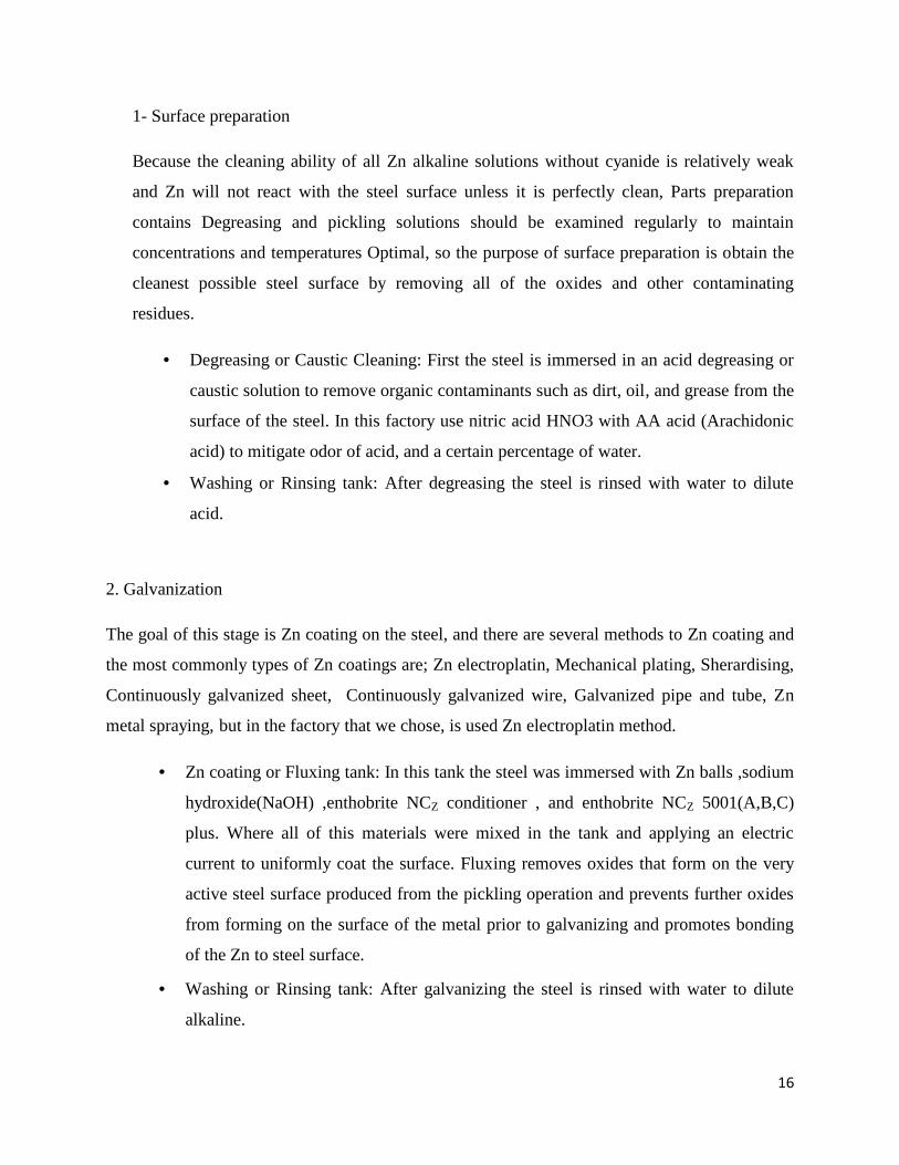
1- Surface preparation
Because the cleaning ability of all Zn alkaline solutions without cyanide is relatively weak
and Zn will not react with the steel surface unless it is perfectly clean, Parts preparation
contains Degreasing and pickling solutions should be examined regularly to maintain
concentrations and temperatures Optimal, so the purpose of surface preparation is obtain the
cleanest possible steel surface by removing all of the oxides and other contaminating
residues.
Degreasing or Caustic Cleaning: First the steel is immersed in an acid degreasing or
caustic solution to remove organic contaminants such as dirt, oil, and grease from the
surface of the steel. In this factory use nitric acid HNO3 with AA acid (Arachidonic
acid) to mitigate odor of acid, and a certain percentage of water.
Washing or Rinsing tank: After degreasing the steel is rinsed with water to dilute
acid.
2. Galvanization
The goal of this stage is Zn coating on the steel, and there are several methods to Zn coating and
the most commonly types of Zn coatings are; Zn electroplatin, Mechanical plating, Sherardising,
Continuously galvanized sheet, Continuously galvanized wire, Galvanized pipe and tube, Zn
metal spraying, but in the factory that we chose, is used Zn electroplatin method.
Zn coating or Fluxing tank: In this tank the steel was immersed with Zn balls ,sodium
hydroxide(NaOH) ,enthobrite NCZ conditioner , and enthobrite NCZ 5001(A,B,C)
plus. Where all of this materials were mixed in the tank and applying an electric
current to uniformly coat the surface. Fluxing removes oxides that form on the very
active steel surface produced from the pickling operation and prevents further oxides
from forming on the surface of the metal prior to galvanizing and promotes bonding
of the Zn to steel surface.
Washing or Rinsing tank: After galvanizing the steel is rinsed with water to dilute
alkaline.

17
3. Post-treatment or Inspection:
Powder coating tank: in a mild solution of sodium dichromate. This solution is
designed to provide a thin Zn chromate layer for the initial protection of Zn surface.
The last step is post treatment and its purpose is paint steel by using PERMAPASS
material.
Washing or Rinsing tank: After powder coating the steel is rinsed with water[16,18].
2.1.3 Factory conditions
The tanks made from Steel lined preferably with PVC (Polyvinylchloride) or other approved
material (in order to prevent stray current) like (PP and PE), and the volume of each tank is 10
m3. For plating the sodium hydroxide to zinc metal ratio should be at least 10:1, operating
condition of cold galvanizing illustrated in Table (2.2), also the typical temperature is 26C°.
Table 2.2: The amount of material which required in the process[6,8].
Tank’s name Material Typical Range
Degreasing or caustic
cleaning
Arachidonic acid (AA)1% from tank’s
concentration-
Nitric acid (HNo3)15% from tank’s
concentration-
Zn coating or fluxing
Zinc metal 12 g/L 10-14 g/L
Sodium hydroxide 120 g/L 110-140 g/L
ENTHOBRITE NCz
DIMENSION A14 ml/L 12-16 ml/L
NCz ENTHOBRITE
DIMENSION B3 ml/L 2-4 ml/L
ENTHOBRITE NCz C 3 ml/L 2-4 ml/L
ENTHOBRITE NCz
CONDITIONER20 ml/L 15-30 ml/L
Powder coating Sodium dichromate 15 ml/L 14-16 ml/L

18
2.2 Galvanization Industry Effluent and its Effects
Despite its important, the galvanization industry as any industry in the world has many risks and
has range of negative effects on the environment and human health as well as animals that come
from chemical substances that used particularly Zn. "It is unfortunate that Zn is almost always
mentioned in conjunction with those other ‘heavy metals’ of ill environmental repute, cadmium
and lead".
When we talk about the environmental risks that we found in this factory we must take in our
concerns the effects of the environmental elements that includes air, water, and soil, as well as
human health.
2.2.1 Air pollution
The contaminants which are discharged whenever the fresh flux and new chemical substances
are added to the basins, also during the immersion of steel into the galvanizing basins these
chemicals would be fly into the air in a very high concentrations particularly Caustic soda, Acid
and particulate matter (PM10), so they make the odor in the place very troublesome and no one
can stay in this place near to these basins. And these emissions especially acid vapor harm the
respiratory system of the workers and cardiovascular systems, also may lead to cancer disease in
the long term exposure. Also effects on animal or plant life, damage to materials of economic
value to society and damage to the environment (e.g., climatic modifications).
2.2.2 Solid waste
A solid waste comes only from chemical plastic tanks, cartons and Zn residue. They disposed in
waste containers without thinking about re-use or recycle it.
2.2.3 Water pollution
The mainly pollution comes from the wastewater that out from all basins in factory, that's
include large amounts of contaminants such as heavy metals (Zn), acids (Nitric acid), fat, grease
oil, alkaline solutions and suspended solids. This wastewater disposed as it into the sewer system
or to the empty land without any remediation, so there are many problems here. When
wastewater goes in to the sewer system, it would be destroying the network because metals

19
accumulate in it, and when it is thrown in to the near land it would be leachate in to the soil and
harm it, the color of land was black and trees was died, and it may leachate and arrive to the
groundwater so water would pollute with acidic, bases components and heavy metals especially
Zn due to the presence of large quantities of it in the wastewater of Galvanization plant as we
said. Large quantities of Zn can be found in soils, so animals will be die and human health
destroy; this is because of some plants can absorb Zn. As a result this would effect on food chain,
habitat and biodiversity.
The factory should dispose wastewater every 10 days from rinsing tanks, so about 30m3 of
wastewater thrown without any treatment which means 90 m3 every month generate wastewater.
Degreasing or acidic wash galvanization Zn wash powder coating powder
coasting cleaning coating wash
Figure 2.2: The rinsing tanks which dispose their wastewater every 10 days.
2.3 Waste Treatment of Galvanization Industry
Treatment plants in Palestine as any treatment plant in the world, include five stages, are pre-
liminary, primary, secondary , tertiary and sludge treatment ,where physical , chemical, and
biological treatment for pollutants will be done ,but industrial wastewater in Palestine especially
galvanization industry are throughout in the wadi , empty lands, and sewer system as it without
any treatment .So we can remediate some of contaminants like inorganic pollutants(heavy
metals) through chemical treatment ,this treatment called pre-treatment , where it is treated in the
factory[19].
Dispose to the empty land and sewer system
20
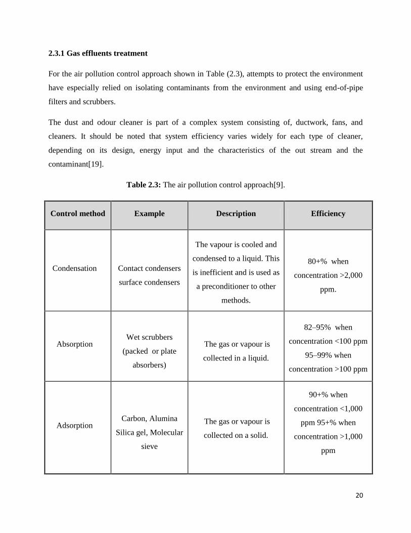
2.3.1 Gas effluents treatment
For the air pollution control approach shown in Table (2.3), attempts to protect the environment
have especially relied on isolating contaminants from the environment and using end-of-pipe
filters and scrubbers.
The dust and odour cleaner is part of a complex system consisting of, ductwork, fans, and
cleaners. It should be noted that system efficiency varies widely for each type of cleaner,
depending on its design, energy input and the characteristics of the out stream and the
contaminant[19].
Table 2.3: The air pollution control approach[9].
Control method Example Description Efficiency
Condensation Contact condensers
surface condensers
The vapour is cooled and
condensed to a liquid. This
is inefficient and is used as
a preconditioner to other
methods.
80+% when
concentration >2,000
ppm.
AbsorptionWet scrubbers
(packed or plate
absorbers)
The gas or vapour is
collected in a liquid.
82–95% when
concentration <100 ppm
95–99% when
concentration >100 ppm
AdsorptionCarbon, Alumina
Silica gel, Molecular
sieve
The gas or vapour is
collected on a solid.
90+% when
concentration <1,000
ppm 95+% when
concentration >1,000
ppm

21
Control method Example Description Efficiency
Incineration Flares, Incinerator
Catalytic incinerator
An organic gas or vapour
is oxidized by heating it to
a high temperature and
holding it at that temp. for
a sufficient time period.
Not recommended when
concentration <2,000
ppm 80+% when
concentration >2,000
ppm
Wet scrubbers Venturi, Wetted filter
Tray or sieve
scrubber
Liquid droplets (water)
collect the particles by
impaction, interception and
diffusion. The droplets and
their particles are then
separated from the gas
stream.
For 5 µm particles,
98.5% at 6.8 w.g.;
99.99+% at 50 w.g.
For 1 µm particles, 45%
at 6.8 w.g.; 99.95 at 50
w.g.
Electrostatic
precipitators
Plate-wire, Flat-plate
Tubular Wet
Electrical forces are used
to move the particles out of
the gas stream onto
collection plates
95–99.5% for 0.2 µm
particles
99.25–99.9+% for 10
µm particles
Filters Baghouse
A porous fabric removes
particulates from the gas
stream. The porous dust
cake that forms on the
fabric then actually does
the filtration.
99.9% for 0.2 µm
particles
99.5% for 10 µm
particles
2.3.2 Soil contamination
There are several technologies or techniques used to treat soil contamination from heavy metals.
For example, use of phytoremediation and biochar technologies in soil remediation from heavy

22
metals. Fellet et al. (2011) tried to use biochar to remediate a multicontaminated mine soil.
Biochar addition didn't result in the decrease of the total heavy metal content of the soil,
however, biochar addition reduced the bioavailability of Cd, Pb and Zn and the mobility
(measured using a leaching experiment) of Cd, Cr and Pb[20].
All ready when we applied the technology of wastewater treatment, soil contamination will be in
safe site.
2.3.3 Water effluents treatment
Water pollution is the main problem that we faced in galvanization industry, because it has a
large amount of Zn. It is one of the metallic chemical elements (called heavy metals) which may
be considered as a “contaminant” if it occurs where it is unwanted, or in a form or concentration
that causes a detrimental human or environmental effect[21].
The most important technique that is used to remove heavy metals from industrial wastewater
effluent is adsorption, and we will talk about it later. Now the most popular techniques are used
including:
• Chemical precipitation: Chemical precipitation is a conventional technology for removing
dissolved metals from wastewater containing toxic metals, which involve the addition of
chemical reagents to the mixture (wastewater) for convert the dissolved metals into solid particle
form ,so a chemical reaction, triggered by the reagent, causes the dissolved metals to form solid
particles[22]. The forming precipitates can be separated from the water by sedimentation or
filtration. And the treated water is then decanted and appropriated discharged or reused [23]. The
process works is dependent upon the kind of metal present, the concentration of the metal, and
the kind of reagent used. Precipitation can be induced by the addition of an alkali, sulfide,
coagulant, or other reagent that will bond with dissolved metal ions [22]. The process usually
uses pH adjustment, addition of a chemical precipitant, and flocculation [24].
• Ion exchange: Ion-exchange processes have been widely used to remove heavy metals from
wastewater[23]. Ion exchange is a reversible chemical reaction wherein an ion (an atom or
molecule that has lost or gained an electron and thus acquired an electrical charge) from a
wastewater solution is exchanged for a similarly charged ion attached to an immobile solid

23
particle. It means that the ions in solutions are replaced by different ions originally present in the
solid[22].
Figure 2.3: Ion exchange is a reaction wherein an ion from a wastewater solution is
exchanged for a similarly charged ion attached to an immobile solid particle[25].
• Membrane filtration: Membrane filtration technologies with different types of membranes
show great promise for heavy metal removal for their high efficiency[23]. Membranes provide
physical barriers that permit the passage of materials only up to a certain size, shape or character.
There are four cross flow, pressure‐driven membrane separation processes currently employed
for liquid/liquid and liquid/solid separation: ultrafiltration (UF), reverse osmosis (RO),
nanofiltration (NF), and microfiltration (MF). Membranes are manufactured in a variety of
configurations including hollow fiber, spiral, and tubular shapes. Each configuration offers
varying degrees of separation[26].
Figure 2.4: Membrane Filtration has a porous act as a barrier that prevent or
allow contaminants pass according to membrane type[27].

24
• Coagulation and flocculation: Coagulation and flocculation followed by sedimentation and
filtration is also employed to remove heavy metal from wastewaters as used to increase particle
size through aggregation[23]. The precipitation process can generate very fine particles that are
held in suspension by electrostatic surface charges. These charges cause clouds of counter-ions
to form around the particles, giving rise to repulsive forces that prevent aggregation and reduce
the effectiveness of subsequent solid-liquid separation processes. Therefore, chemical coagulants
are often added to overcome the repulsive forces of the particles. The three main types of
coagulants are inorganic electrolytes (such as alum, lime, ferric chloride, and ferrous sulfate),
organic polymers, and synthetic polyelectrolytes with anionic or cationic functional groups. The
addition of coagulants is followed by low-sheer mixing in a flocculator to promote contact
between the particles, allowing particle growth through the sedimentation phenomenon called
flocculant settling[24].
Figure 2.5: Coagulation and flocculation based on adding coagulants which allowing particles
growth, then contaminants will be settling[28].
• Flotation: Flotation has nowadays found extensive use in wastewater treatment. Flotation has
been employed to separate heavy metal from a liquid phase using bubble attachment, originated
in mineral processing. Dissolved air flotation (DAF), ion flotation and precipitation flotation are
the main flotation processes for the removal of metal ions from solution. DAF is to allow micro-
bubbles of air to attach to the suspended particles in the water, developing agglomerates with
lower density than water, causing the flocs to rise through the water and accumulating at the
surface where they can be removed as sludge. Ion flotation has been shown a promising method
for the removal of heavy metal ions from wastewaters[23].

25
Figure 2.6: Flotation has been employed to separate heavy metal from a liquid phase using
bubble of air to attach to the suspended particles in the water[29].
• Electrochemical treatment: Electrochemical methods involve the plating-out of metal ions on a
cathode surface and can recover metals in the elemental metal state[23]. There are two typed are:
- Electrocoagulation (EC): has been used industrially and demonstrated its superior performance
in treating effluents containing suspended solids, oil and grease, and even organic or inorganic
pollutants that can be flocculated.
- Electroflotation (EF): is widely used in the mining industries and is finding increasing
applications in wastewater treatment[30]. EF is a solid/liquid separation process that floats
pollutants to the surface of a water body by tiny bubbles of hydrogen and oxygen gases
generated from water electrolysis[23].
Figure 2.7: Electrochemical treatment involve the plating-out of metal ions on a cathode surface
and can recover metals in the elemental metal state[31].

26
2.4 Heavy Metals
The term of heavy metals which classified from an inorganic contaminates, refer to any metallic
chemical element that has a relatively high density greater than 5 g/cm3 and atomic number
above 20, and is toxic or poisonous at low concentrations. Examples of heavy metals include
mercury (Hg), cadmium (Cd), arsenic (As), chromium (Cr), thallium (Tl), zinc (Zn) and lead
(Pb)[32].
Inorganic contamination of aquatic environments is caused by naturally occurring substances
(fluoride, arsenic, and boron), industrial waste (zinc, mercury, cadmium, chromium, cyanide, and
others), agriculture and domestic waste (nitrogen compounds), and systems for the distribution of
drinking water (aluminum, copper, iron, lead, and zinc)[33].
In the Table (2.4), WHO guideline for drinking water quality recommended values for 18
inorganic substances.
Table 2.4: Values of inorganic substances in drinking water according WHO[33].
Compounds Guideline Value(mg/L)
Antimony 0.018
Arsenic 0.011Barium 0.700Boron 0.010
Cadmium 0.003Chromium 0.050
Copper 2.000Cyanide 0.070Fluoride 1.500
Lead 0.010
Manganese 0.500
Mercury 0.001
molybdenum 0.070
Nickel 0.020
Nitrate 50.00
Nitrite 3.000
Selenium 0.010
uranium 0.009

27
While the Environmental Protection Agency (EPA) according the maximum Concentration
levels (MCL) for inorganic contaminates regulated as Table (2.5).
Table 2.5: The MCL for inorganic contaminates regulated in U.S. (EPA)[24].
While the EPA has established National Secondary Drinking Water Regulations (NSDWRs) that
set non-mandatory water quality standards for 15 contaminants in Table (2.6). These
contaminants may cause aesthetic effects like taste, odor, or color in drinking water. EPA
recommends secondary standards to water systems but does not require systems to comply.
However, states may choose to adopt them as enforceable standards.
Compounds MCL(mg/L)
Antimony 0.006
Arsenic 0.000
Asbestos 7 Million fibers/Per Liter
Barium 2.0000
Beryllium 0.0040
Cadmium 0.0050
Chromium 0.1000
Copper 1.3000
Cyanide 0.2000
Fluoride 4.0000
Lead 0.0000
Mercury 0.0020
Nickel 0.1000
Nitrate 10 as Nitrogen
Nitrite 1 as Nitrogen
Selenium 0.0500
Thallium 0.0005

28
Tale 2.6: The national secondary drinking water regulations in EPA[34].
Contaminant Secondary MCL Noticeable Effects
Aluminum 0.05 to 0.20mg/L colored water
Chloride 250.00 mg/L salty taste
Color 15.00 color units visible tint
Copper 1.00 mg/L metallic taste; blue-green staining
Corrosivity Non-corrosivemetallic taste; corroded pipes/ fixtures
staining
Fluoride 2.00 mg/L tooth discoloration
Foaming agents 0.50 mg/L frothy, cloudy; bitter taste; odor
Iron 0.30 mg/Lrusty color; sediment; metallic taste;
reddish or orange staining
Manganese 0.05 mg/Lblack to brown color; black staining;
bitter metallic taste
Odor3 TON (threshold odor
number)"rotten-egg", musty or chemical smell
pH 6.50 - 8.50low pH: bitter metallic taste; corrosion
high pH: slippery feel; soda taste;deposits
Silver 0.10 mg/Lskin discoloration; graying of the white
part of the eye
Sulfate 250.00 mg/L salty taste
Total DissolvedSolids (TDS)
500.00 mg/Lhardness; deposits; colored water;
staining; salty taste
Zinc 5.00 mg/L metallic taste
Zn is a natural component of the earth’s crust and an inherent part of our environment. It is
present in rock, soil, air, and water. Plants, animals and humans also contain Zn. The average
natural level of Zn in the earth’s crust is 70 mg/kg (dry weight), ranging between 10 and 300
mg/kg[35]. Zn is a transition metal that occurs in the center of the periodic table[36], and its
atomic number 30, atomic mass is 65.38. It has a number of characteristics that make it a well-
suited corrosion protective coating for iron and steel products. The first use of it in construction
was in 79 AD. Zn is an excellent corrosion resistance in most environments accounts for its

29
successful use as a protective coating on a variety of products and in many exposure
conditions[37]. Although Zn is essential micronutrient for most of industry, environment, even
human, but it also main problem as heavy metal in wastewater.
2.5 Adsorption
2.5.1 Introduction
Over the last few decades adsorption has gained paramount importance in industry and
environmental protection as a purification and separation process[30]. Adsorption is integral to a
broad spectrum of physical, biological, and chemical processes and operations in the
environmental field. Purification of gases by adsorption has played a major role in air pollution
control, and adsorption of dissolved impurities from solution has been widely employed for
water purification[38].
Now adsorption viewed as a superior method for wastewater treatment and water reclamation; as
an effective and economic method especially in heavy metals treatment. The adsorption process
offers flexibility in design and operation and in many cases will produce high-quality treated
effluent. In addition, because adsorption is sometimes reversible, adsorbents can be regenerated
by suitable desorption process[23].
The most general definition describes adsorption as an enrichment of chemical species from a
fluid phase on the surface of a liquid or a solid, when a liquid is brought in to contact with a
solid, part of it is taken up by the solid. The solid that takes up the liquid or the solute is called
the "adsorbent", and the liquid taken up on the surface is called "adsorbate"[39].
The term "absorption" is totally differing from "adsorption". Absorption is assimilation of
molecular species throughout the bulk of the solid or liquid, so it's a bulk phenomenon, in which
contaminants are dissolved in bulk. While adsorption is accumulation of the molecular species at
the surface rather than in the bulk of the solid or liquid, so it's a surface phenomenon in which
adsorbate trans to adsorbent as amass transfer[40].
2.5.2 Adsorption Process
Adsorption works on the principle of adhesion. The process of adsorption involves separation of
a substance from one phase accompanied by its accumulation or concentration at the surface to

30
another ,the adsorbing phase is the "adsorbent", and the material concentrated or adsorbed at the
surface of adsorbing phase is the "adsorbate" .The process can take place in any of the following
systems: liquid-gas, liquid-liquid, solid-liquid and solid-gas. in focusing on wastewater treatment
the system is solid-liquid[30]. Depending on the nature of attractive forces existing between the
adsorbate and adsorbent, adsorption can be classified as: Physical adsorption or physisorption
and Chemical adsorption or chemisorptions. In physical adsorption, the forces of attraction
between the molecules of the adsorbate and the adsorbent are weak Van der Waals' type. Since
the forces of attraction are weak, the process of physisorption can be easily reversed by heating
or decreasing the concentration of the adsorbate. In contrast, the forces of attraction between the
adsorbate and the adsorbent in chemisorption are very strong(covalent and ionic bonds), the
molecules of adsorbate form chemical bonds with the molecules of the adsorbent present in the
surface[41].
Figure 2.8: Adsorption process which involves separation of a substance from one phase
accompanied by its accumulation at the surface to another ,the adsorbing phase is the
"adsorbent", and the material adsorbed at the surface of adsorbing phase is the "adsorbate"[42].
More of the solid adsorbents process has a complex porous structure that consists of pores of
different sizes and shapes. In terms of the science of adsorption, the total porosity is usually
classified into three groups; microspores (smaller than 2 nm), mesopores (in the range of 2 to
50 nm), and macrospores (larger than 50 nm). The adsorption in microspores is essentially a
pore-filling process because sizes of microspores are comparable to those of adsorbate
molecules. All atoms or molecules of the adsorbent can interact with the adsorbate species that is
fundamental difference between adsorption in microspores and larger pores like meso- and
31
macrospores, thus the size of microspores determines the accessibility of adsorbate molecules to
the internal adsorption surface[30].
Adsorption refers to the existence of a higher concentration of any particular component at the
surface of a liquid or a solid phase. Adsorption is invariably accompanied by evolution of heat,
i.e. it is an exothermic process. Its mean ∆H of adsorption is always negative, but at some cases
it’s an endotherm[43].
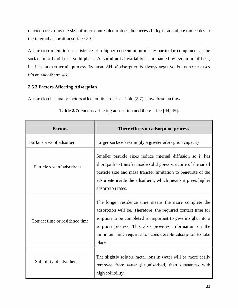
2.5.3 Factors Affecting Adsorption
Adsorption has many factors affect on its process, Table (2.7) show these factors.
Table 2.7: Factors affecting adsorption and there effect[44, 45].
Factors There effects on adsorption process
Surface area of adsorbent Larger surface area imply a greater adsorption capacity
Particle size of adsorbent
Smaller particle sizes reduce internal diffusion so it has
short path to transfer inside solid pores structure of the small
particle size and mass transfer limitation to penetrate of the
adsorbate inside the adsorbent; which means it gives higher
adsorption rates.
Contact time or residence time
The longer residence time means the more complete the
adsorption will be. Therefore, the required contact time for
sorption to be completed is important to give insight into a
sorption process. This also provides information on the
minimum time required for considerable adsorption to take
place.
Solubility of adsorbentThe slightly soluble metal ions in water will be more easily
removed from water (i.e.,adsorbed) than substances with
high solubility.

32
Factors There effects on adsorption process
Affinity of the solute for the
adsorbent
If the surface of adsorbent is slightly polar, the non-polar
substances will be more easily picked up by the adsorbent
than polar ones.
Size of the molecule with respect
to size of the pores
Large molecules may be too large to enter small pores. This
may reduce adsorption independently of other causes.
Degree of ionization of the
adsorbate molecule
More highly ionized molecules are adsorbed to a smaller
degree than neutral molecules.
pH The removal efficiency increases with increasing initial pH.
Effect of initial concentration
At high-level concentrations, the available sites of
adsorption become fewer. high concentration will create and
activate of some new activation sites and occupies the
available bending sites faster causing the remaining solutes
unable to bind on to the adsorbent.
Dosage effectsThe removal efficiency is generally increased as the
concentration dose increases over these temperature values
TemperatureAdsorption increases at low temperature conditions. Since
adsorption is an exothermic process
Pressure
Adsorption increases with raising the pressure to a certain
extent till saturation level is achieved. After saturation level
is achieved no more adsorption takes place no matter how
high the pressure is applied

33
2.5.4 Adsorption isotherms
Adsorption isotherms or known as equilibrium data are the fundamental requirements for
adsorption systems design. The equilibrium is achieved when the capacity of the adsorbent
materials is reached, and the rate of adsorption equals the rate of desorption. Theoretically
adsorption capacity of an adsorbent can be calculated with an adsorption isotherm. There are
basically four well established types of adsorption isotherm according type of bonding and No.of
layers are: linear, Langmuir, BET , and the Freundlich adsorption isotherms[44].
The significance of adsorption isotherms comes from that they show the amount of material
which is adsorbed on the surface at a particular temperature which depends upon the amount of
that substance in the liquid phase (concentration) that is in contact with the surface. That mean,
the amount of sorbed solute versus the amount of solute in solution at equilibrium[44].
The extent of adsorption is usually measured by coverage θ which is given by:
ϴ= (2.1)
1- Linear adsorption isotherm
The simplest adsorption isotherm to fit to data because its assumes that linear partitioning,
unlimited number of available sorption sites[46].
qe = K.Ce (2.2)
Where: qe = amount of solute adsorbed per unit wheight of solid at equilibrium(g/g), or (mg/g)
Ce = Concentration of solute in equilibrium with mass of solute sorbed on solid (mg- solute/L),
K = constant (kg/m3) [47].
2- Langmuir adsorption isotherms
Langmuir adsorption isotherm describes quantitatively the formation of a monolayer (single
layer) of adsorbate on the outer surface of the adsorbent, and after that no further adsorption
takes place[44].The Langmuir adsorption is based on the view that every adsorption site is

34
identical and energically equivalent (thermodynamically, each site can hold one adsorbate
molecule)[44].
qeqe ceK+ ce (2.3)
3- Freundlich adsorption isotherms
Freundlich isotherm is commonly used to describe the adsorption characteristics for the
heterogeneous surface. It represents an initial surface adsorption followed by a condensation
effect resulting from strong adsorbate-adsorbent interaction[44].
qe = K . Cen (2.4)
4- Brunauer, Emmett and Teller (BET ) isotherm
While the Langmuir isotherm provides a simple picture for looking at surface adsorption, but
when more than one molecules can adsorb to each site on the adsorbent; a better approximation
for this process is to use the BET Isotherm (named for its inventors, Brunauer, Emmett, and
Teller) which allows for multilayered adsorption on isotherm. It assumes that a Langmuir
isotherm applies to each layer and that no transmigration occurs between layers. It also assumes
that there is equal energy of adsorption for each layer except for the first layer[48, 49]. . . / (2.5)
Kb = a parameter related to the binding intensity for all layers.
CS =saturation (solubility limit) concentration of the solute. (mg/L)
When Ce << CS and KB >> 1 and Kad = KB /Cs BET isotherm approaches Langmuir
isotherm[47].

35
2.5.5 Adsorbent types
1- Industrial adsorbents
• Carbon adsorbents: Are widely used in the removal of heavy metal contaminants it has a
porous carbon structure, which contains small amounts of different heteroatoms such as oxygen
and hydrogen. Also contain variable amounts of mineral matter (ash content) depending on the
nature of the raw material used as precursor. There are many form of Carbon adsorbents as
active carbons, active carbons fibers, molecular carbon sieves and carbon nano materials[50]. Its
usefulness derives mainly from its large micropore and mesopore volumes and the resulting high
surface area. Nowadays, the depleted source of commercial coal-based AC results in the increase
of price[23]. It has a range of applications from gas, water, and metal purification to air filtration.
• Activated alumina: Is an adsorbent made of aluminum oxide (Al2O3). It is used as a desiccant
for drying gases and air and as a fluoride filter for drinking water. It has specific use as a silica
gel replacement in certain environments due to its thermal shock resistance and physical
constancy when immersed in water.
• Silica gel or silicon dioxide: Is a common desiccant used in food preservation, humidity
control, and various medical devices. It has a higher water absorption capacity than clay silicates,
it is very inert, and it can be regenerated through heating.
• Organic polymers: Are chains of repeating carbon based molecules used as adsorbents in size-
exclusion chromatography and gas separation processes with high retention power and
selectivity. Most do not require disposal and the regeneration process is environmentally
friendly.
• Molecular sieves or zeolites: Are naturally occurring adsorbents with uniform pore size that
can be tuned to be highly selective. They are used as dehumidifiers and air purifiers due their
high retention and adsorption capacities even at high temperatures. Zeolites are often combined
with activated carbon for combined effectiveness.
36
2- Natural adsorbents
• Calcium sulfate: Is a natural mineral that is chemically stable, and readily retains its captured
moisture. It costs little but also has a low adsorbency capacity and is best suited for small
moisture capture operations or laboratory use.
• Calcium oxide: Is a slow but strong and high capacity desiccant also known as quicklime. It is
caustic and expands as it adsorbs and does so over several days. It is most effective in high
humidity environments
• Clay or clay silicates: Are natural mineral absorbents that are used as spill cleaning agents,
sealants, and packing materials because they are inexpensive, inert, and have a quick capture
rate. However they begin to desorb at temperatures above 120°F[51].
And we have a Low-cost adsorbents has been investigated as a replacement for costly current
methods[52]. Nearly 100 papers talk about low cost adsorbents have demonstrated outstanding
removal capabilities for certain metal ions as compared to activated carbon. Adsorbents that
stand out for high adsorption capacities are chitosan (Hg2+, Cr6+, and Cd2+), zeolites (Pb2+ and
Cd2+), waste slurry (Pb2+, Hg2+, and Cr6+), and lignin (Pb2+). These adsorbents are suitable for
inorganic effluent treatment containing the metal ions. It is important to note that the adsorption
capacities of the adsorbents vary depending on the characteristics of the individual adsorbent, the
extent of chemical modifications, and the concentration of adsorbate[53]. Other low cost
adsorbents , adsorbents Agricultural and industrial waste by-products such as rice husk, peanut
husk, charcoal, fly ash, biomass, and fly ash[54].
Moreover, during the few years new classes of mineral adsorbents have been developed[55],
specifically Nanotechnology as adsorbents in all form; particles, tubes, rods, membrane, and
fibers[56].
Nanoparticles have a wide range of applications, as in the technological and environmental
challenges in the areas of solar energy conversion, catalysis, medicine, and water treatments.
Many studies have addressed nanoparticles, mainly metal oxides, as effective and efficient
adsorbents in the cleanup of environmental contaminants, mainly because nanoparticles can
penetrate into the contamination zone where microparticles cannot.

37
In general, the term nanotechnology related to the preparation and application of materials at
nanoscale (1–100 nm) has emerged as a fascinating area of interest for removal of various
contaminants especially from wastewater effluents[6].
Nanoparticles in adsorption process are most importantly used as adsorbents for the removal of
metal ions, and the commonly used are oxides of aluminum, iron, and titanium. Some workers
have used nanoparticles of iron oxide for efficient removal of metal ions due to their high surface
areas and ease of preparation[57].

38
Chapter Three
Experimental Work

39
3.1 Materials
Four real samples of galvanization wastewater were obtained from a local galvanization factory
(Ghtasheh Company, Fawwar, Hebron, Palestine). These samples were collected from different
tanks, sample 1 was collected from after acidic tank, while sample 2 was taken from galvanizing
tank, after galvanizing tank where zinc wash sample 3 was taken, and sample 4 from wash of
powder coating tank as shown as in figure (3.1), (Zinc Chloride (ZnCl2), anhydrous, 98+%,
AlfaAesar, Germany) as stock solution, ICP Multi Element Standard Solution at concentration
40mg/L, obtained from (MERK, Germany), Limestone was obtained locally from (caves) and it
was sieved to very small size used as adsorbent,( Zinc Nitrate Zn(NO3)2 as stock solution, 98+%
purity, sigma aldrich, Germany), Activated Carbon, and magnetic nanoparticles (Iron oxide
powder (Fe3O4), 98+%, IoLiTec Ionic Liquids Technologies, Heilbronn, Germany).
3.2 Method
3.2.1 Wastewater characteristics
Wastewater characteristics of the real samples at different time intervals, these were analyzed
before treatment including pH (PCE-228 pH-meter), chemical oxygen demand COD (COD
Reactor CR25), electrical conductivity (EC) and total dissolved solid (TDS) (Electrical
conductivity meter EE002), concentration of elements in galvanization process (ICP-Optical
Emission Spectrometer (ICP-OES)), and turbidity (Waterproof Portable TN100 meter).

40
Degreasing or acidic wash galvanization Zn wash powder coating powder
coasting cleaning coating wash
Figure 3.1: Real wastewater samples were collected from different tanks in galvanization
process, these tanks are: acidic wash (sample 1), galvanization (sample 2), Zn wash (sample 3),
and powder coating wash (sample 4).
3.2.2 Adsorption (Batch tests)
Adsorption experiments were carried out in a batch technique by using different types of
adsorbents and solutions. According to the different adsorbents that were used; natural
adsorbent, where 5 g of limestone was added to 100 ml of ZnCl2 solution, and mixed on a stirrer
at 100 rpm for 15, 30 minutes and 1 hour at constant pH 6. After that, the lime stone was
separated by filtering from the aqueous solution, and E.C (Electrical conductivity meter EE002)
was measured.
The second adsorbent that was used is Activated carbon, which were used with different two
solutions, the first solution where done by 0.5 g of activated carbon added to 100 ml of ZnCl2
solution. and the second solution is Zn(NO3)2, where 0.1 g of activated carbon was added to 100
ml of Zn(NO3)2, and adsorption process was carried out at same conditions for these solutions,
mixed on a stirrer at 100 rpm for 5, 10, 15, 20, 30 and 60 minutes, and pH 6. Then adsorbent
separated by filtering from solution, and E.C and concentration of zinc were measured.
The final adsorbent that was used is Magnetic Iron Oxide nanoparticles, were used with different
solutions, the first solution where done, 0.1 g of magnetic iron oxide nanoparticles were added to
50 ml of ZnCl2 solution, mixed at 99 rpm on rotary shaker (Intelli-mixer), for 10, 20, 30, 60,
Sample1
Sample2 Sample
4
Sample3

41
120, and 180 minutes. While 1 g of magnetic iron oxide nanoparticles were added to 50 ml of
ICP standard solution mixed at 99 rpm on rotary shaker (Intelli-mixer), for 10, 20, 30 minutes.
Also 0.5 g of magnetic iron oxide nanoparticles were added to 50 ml of Zn(NO3)2 solution
mixed at 99 rpm on rotary shaker, for 10, 30, 60, 180, 300 minutes and overnight at pH 7. Finally
0.2 g of magnetic iron oxide nanoparticles were added to 100 ml of real sample (from tank 4)
mixed on a stirrer at 100 rpm for 10, 30 ,120 and 150 minutes, and this real sample was tested
with nanoparticles mixed on a shaker at 99 rpm, for 10, 30, 60, 300 minutes and overnight. Then
the magnetic nanoadsorbent was separated, and the aqueous concentrations were analyzed by
ICP-Optical Emission Spectrometer (ICP-OES). And E.C (Electrical conductivity meter EE002).
Various parameters were studied like initial concentration and pH, solution with different
concentration were prepared (5.17, 2.59, 0.65, 0.32, and 0.16) at equilibrium time 3 hour and
adsorbent dosage 0.1 gnano/50mL real sample, also various pH range (2, 5, 7, 10, 11, and 13)
was studied at the same experimental condition. These experiments were conducted at room
temperature.

42
Chapter Four
Results and Discussion

43
4.1 Wastewater Characteristics
The real wastewater samples characteristics, including pH, E.C, TDS, and turbidity were tested
over aperiod of 60 days as shown in Table (4.1).
Table 4.1: pH, E.C, turbidity, and TDS characterization tests of real wastewater samples fromlocal galvanization industry over 60 days.
Table (4.1) shows the characteristics of wastewater samples collected over six time intervals.
Sample 2 which was obtained from fluxing or gslvanization solution tank showed the highest
values of all tested properties since its tank contained zinc balls and alkaline solutions. Samples
(1, 3, and 4) were collected from the rinsing tanks and the properties of wastewater varies
according to their sequence in the galvanization process. For instanes, sample 1 has the lowest
pH values as this sample was obtained from the rinsing tank after acidic treatment of metals, and
Sample deviceInterval time
2 3 4 5 61
1
pH 0.22 0.44 0.29 1.35 3.22 2.72
Turbidity(NTU) 7.51 9.20 17.54 6.28 21.3 3.56
E.C(ms) 30.6 31.4 35.6 39.6 2.56 4.90
TDS(ppm)*100 202 227 250 267 20.0 362
2
pH 13.80 14.40 14.03 14.83 14.78 14.68
turbidity 30.00 56.4.0 36.70 41.00 65.30 309.0
E.C 156.1 157.0 155.9 156.2 166.9 178.9
TDS*100 1071 1035 1107 1083 1260 1191
3
pH 13.0 12.88 13.01 12.64 7.440 11.43
turbidity 7.96 8.260 11.29 2.590 2.650 6.180
E.C 7.20 7.980 8.270 9.200 1.164 1.708
TDS*10 483 489.0 573.0 596.0 76.10 118.5
4
pH 8.72 7.61 9.82 8.00 7.45 6.93
turbidity 2.59 0.68 2.75 0.58 6.99 2.18
E.C 1.15 1.1237 1.182 1.267 1.02 1.051
TDS 752 748 785 794 680 700

44
it has the highset turbidity values because this tank contaminated with fats and oils, where
sample 3 has the highst pH values as this sample was obtained from the rinsing tank after fluxing
tank which is highly alkline, and sample 4 which was obtained from rinsing tank after powder
coating tank, has the lowest values of all tests; because this sample was obtained from the last
tank which has little amount of dissolved solids. In general wastewater samples have low COD
values, so they have a little magnetude of organic matters.
Where comparing the values of the tested properties over time intervals (60 days), sample 2
water chaercterestics have a stable range because the water in this tank wasn’t change, only the
substances were added at different times to preserve substance’s concentration, about rinsing
tanks , that amajor change was occurred after time interval 4 which indicate that water in these
tanks were recharged for example TDS that shown in figure (4.1).
Figure 4.1: Several values of TDS in rinsing tanks with different time intervals along sixty days.
Real samples which obtained from rinsing tanks (1, 3, and 4) in the galvanization process,
had these elements (Fe, Al, Cu, Mn, Pb, Cd, Zn, Co, Cr, B, Na, K, Mg, Ca, Ni), were
analyzed to find their concentration as shown in Table (4.2), and the concentration of Zn in
sample 2 was 1494 mg/L.
0
100
200
300
400
500
600
700
800
900
0 1 2 3 4 5 6 7
TD
S (p
pm)
Interval time
sample 1*100
sample 3* 10
sample 4

45
The concentration of elements in galvanization industry indicate that the wastewater for this
industry is highly contaminated with toxic elements which requires proper treatment process
before discharged to empty land or sewer system. The next section presents the results on
applying adsorption technique for treat of wastewater contain toxic metals.
Table 4.2: Concentration of elements from rinsing tanks in galvanization industry.
Sample Fe Al Cu Mn Pb Cd Ni
1 0.267 1.095 0.044 0.002 0.000 0.008 0.000
3 297.2 0.927 0.295 5.158 0.729 0.000 0.405
4 6.935 0.012 0.002 0.145 0.000 0.000 0.022
Sample Zn Co Cr B Na Ca K Mg
1 3.707 0.003 0.062 0.000 1626 7.261 12.32 0.173
3 16.72 0.063 0.441 0.000 57.79 111.2 8.503 39.66
4 0.843 0.006 20.79 0.000 108.6 93.63 8.066 45.51
4.2 Adsorption Tests
Adsorption tests were performed on model solutions and real wastewater samples that werecollected from local galvanization factory.
4.2.1 Adsorption test on several model solutions
Various model solutions like (ZnCl2, ICP standard, and Zn(NO3)2) were tested to determine thefeasibility of the adsorption process on these solutions.
The result of adsorption process on ZnCl2 solution by using limestone as adsorbent was
conducted by E.C as shown in figure (4.2). On the other hand, figure (4.3) demonstrated the
adsorption for ICP standard solution with magnetic nanoadsorbent was carried by ICP device,
the elements concentrations decrease with time, and this relationship can be described by an
exponential regression.

46
Figure 4.2: E.C value of ZnCl2 as a function of contact time for adsorption experiments with a
lime dose of 5 g/100 mL on a stirrer (100 rpm) at room temperature, and pH 6.
Lime stone adsorbent for ZnCl2 solution didn’t give an effective result, it just show a very weak
adsorption that couldn't be taken into consideration, this result was due to the alkaline nature of
lime stone where it’s have the capability to buffer the solution, so it will increase the pH of the
solution, this variation of the pH can affect the adsorption process, or it was due to the
instability of the ZnCl2 solution.
Figure 4.3: Concentration of different elements as a function of contact time for adsorptionexperiments on rotary shaker (99rpm) with iron nanoparticles 1g/50 mL.
12.2
12.4
12.6
12.8
13
13.2
13.4
13.6
0 20 40 60
E.C
(m
s)
Time (min)
30.5
35.5
40.5
45.5
50.5
55.5
60.5
0 5 10 15 20 25 30 35
Con
cent
rati
on o
f m
etal
s (p
pm)
Time (min)
AL
Mn
Pb
Cd
Zn
Co
Cr
B
Ni
Cu

47
For using iron oxide nanoadsorbent with ICP standard solution, it was noticed that Zn
concentration was decreasing according to the time factor of adsorption process, but with little
change. According to the other elements, Cd concentration had an effective decrease, while for
B, Cr, Co, Ni, and Pb they had the same concentration approach of zinc in decrease.
But some elements had an increase in their concentrations which included Cu, Al, and Mn as
shown in figure (4.3). The interpret of this results; increased could be attributed that some of the
nanoparticles escaped to the supernatant which was detected in the samples. Beside the
nanoparticles seem to be contaminated with Al and Mn; which resulted in an increase in their
concentrations.
The expression of results that obtained depending on the relationship between percentage
removal which calculate according Equ.(4.1) and time factor of adsorption process as shown in
Figure (4.4), that indicate the total percentage removal was reached 70%, also the percentage
removal of Cd, Zn, B, Cr, Co, Ni and Pb was increased respectively.
Percentage Removal (%) =˳ ˳ ∗ 100% (4.1)
Figure 4.4: Percentage removal of elements as a function of contact time for adsorption
experiments with iron oxide nanoparticles 1g/50 mL.
-0.05
0
0.05
0.1
0.15
0.2
0.25
0 5 10 15 20 25 30 35
Per
cent
age
met
als
rem
oval
Time (min)
Cd
Zn
Ni
B
Co
Pb
Cr

48
The difference in the percentage removal of elements maybe explained that the nanoparticles is
more selective to certain heavy metals than others, and the low percentage removal was due to
the fact related to the active sites. Adsorption’s results of ZnCl2 and Zn(NO3)2 solutions were not
reproducible, so it was not efficient, and this is might be attributed to the Zn ions instability.
Figure 4.5: The concentration of ZnCl2 as a function of contact time for adsorption experiment
on rotary shaker at 99 rpm, iron nanoparticles dose of .1 g/50 mL, at room temperature, and pH6.
Figure (4.5) illustrate the results of ZnCl2 solution that were obtained from ICP device which are
not stable, so there is no adsorption occurs with nanoparticles here. Then activated carbon was
used as adsorbent for the same solution, and the results that were obtained from E.C device
showed in figure (4.6).
Figure 4.6: E.C value of ZnCl2 as function of contact time for adsorption experiment on a
stirring rate 100 rpm, activated carbon dose of .5 g/50 mL, at room temperature, and pH 6.
The results obtained from E.C device are approximately having the same behavior of ICP device
200
220
240
260
280
300
320
340
360
380
0 40 80 120 160 200
Con
cent
rati
on (
mg/
L)
time (min)
1530
1535
1540
1545
1550
1555
1560
0 10 20 30 40 50 60 70
E.C
(m
s)
time (min)

49
results. This indicates that E.C can be used as an element’s concentration indicator. As seen from
figures (4.5, 4.6) the solution (ZnCl2) is instable.
Figure 4.7: E.C, and Zn concentration values of Zn(NO3)2 as function of contact time for
adsorption experiment, on a stirring rate 100 rpm, activated carbon dose of .1 g/100 mL, at room
temperature, and pH 6.
According to the two curves that shown in figure (4.7), the adsorption process of Zn(NO3)2
solution occur through one hour and the concentration decreases nearly from 160 to 100 mg/L.
the same test was repeated at the same conditions but over 24 hour, and the results appearing in
figure (4.8).
Figure 4.8: E.C, and Zn concentration values of Zn(NO3)2 as function of contact time for
adsorption experiment, on a stirring rate 100 rpm, activated carbon dose of .1 g/100 mL, at room
temperature, and pH 6.
0.69
0.695
0.7
0.705
0.71
0.715
0.72
0.725
0.73
80
90
100
110
120
130
140
150
160
170
0 20 40 60 80
Con
cent
rati
on (
mg/
L)
time(min)
E.C
0.580.60.620.640.660.680.70.720.740.760.78
152
154
156
158
160
162
164
166
168
0 500 1000 1500
Com
cent
rati
on(m
g/L
)
time (min)
E.C
(ms)
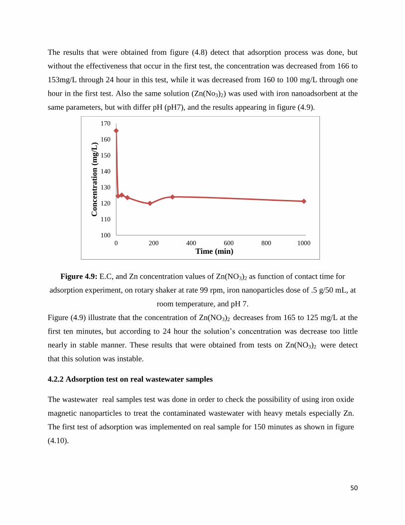
50
The results that were obtained from figure (4.8) detect that adsorption process was done, but
without the effectiveness that occur in the first test, the concentration was decreased from 166 to
153mg/L through 24 hour in this test, while it was decreased from 160 to 100 mg/L through one
hour in the first test. Also the same solution (Zn(No3)2) was used with iron nanoadsorbent at the
same parameters, but with differ pH (pH7), and the results appearing in figure (4.9).
Figure 4.9: E.C, and Zn concentration values of Zn(NO3)2 as function of contact time for
adsorption experiment, on rotary shaker at rate 99 rpm, iron nanoparticles dose of .5 g/50 mL, at
room temperature, and pH 7.
Figure (4.9) illustrate that the concentration of Zn(NO3)2 decreases from 165 to 125 mg/L at the
first ten minutes, but according to 24 hour the solution’s concentration was decrease too little
nearly in stable manner. These results that were obtained from tests on Zn(NO3)2 were detect
that this solution was instable.
4.2.2 Adsorption test on real wastewater samples
The wastewater real samples test was done in order to check the possibility of using iron oxide
magnetic nanoparticles to treat the contaminated wastewater with heavy metals especially Zn.
The first test of adsorption was implemented on real sample for 150 minutes as shown in figure
(4.10).
100
110
120
130
140
150
160
170
0 200 400 600 800 1000
Con
cent
rati
on (
mg/
L)
Time (min)

51
Figure 4.10: The concentration and the percentage of removal of Zn as a function of contact
time for adsorption experiments at stirring rate 100 rpm, iron nanoparticles dose of .2 g/100 mL,
at room temperature and pH13.
Figure (4.10) shows change in concentration of Zn along 150 minutes, where Zn concentration
was decreased from 5 to 1 mg/L at the first 10 minutes. After this time period, the concentration
of Zn was decreasing slightly, and the percentage of removal after 150 minutes reached 92.6%.
The second test of adsorption was left for 24 hours and the obtained results were shown in
figure (4.11).
Figure 4.11: The concentration and the percentage of removal of Zn as a function of contact
time for adsorption experiments at stirring rate 100 rpm, iron nanoparticles dose of .2 g/100 mL,
at room temperature and pH13.
0
10
20
30
40
50
60
70
80
90
100
0
1
2
3
4
5
6
0 50 100 150 200
Con
cent
rati
on(m
g/l)
Time (min)
Zn concentration(mg/L)
prsentage removal
presentage removal
0
20
40
60
80
100
120
0
1
2
3
4
5
6
0 200 400 600 800 1000 1200 1400
Con
cent
rati
on o
f Zn
(mg/
L)
Time (min)
Zn concentration (mg/L)
persentage removal
persentage removal

52
Figure (4.11) illustrate the adsorption test for the real sample left in contact with the adsorbent
for 24 hours. At this time removal percentage reached its maximum value of 95% .Equilibrium
in this case was reached after 3h, so to get more accurate results the solution was left overnight,
and from the equilibrium data the adsorption capacity was calculated in order to determine the
adsorption isotherm as shown in figure (4.12). Tests were implemented for real sample with
different operating conditions to study the efficiency from PH and initial concentration effects.
Figure 4.12: Adsorption capacity for various final concentrations as function of equilibrium of
concentration on rotary shakier rate 99 rpm at 3 hours, iron nanoparticles dose of .1 g/50 mL, at
room temperature and pH 13.
The concentrations (Co and Ce) were calculated in order to find the adsorption capacity of iron
nanoparticle at equilibrium (qe) according to the mass balance at Equ (4.2). Figure (4.14) shows
the adsorption capacity in (mg/g) as function of equilibrium concentration in (mg/L). This
adsorption capacity was used to acquire the equilibrium adsorption isotherm, under the
experimental condition obeyed frindlich isotherm.
qt = (Co –Ce)* (4.2)
0
0.5
1
1.5
2
2.5
3
0 0.05 0.1 0.15 0.2 0.25 0.3
qt (
mg/
g)
Ct (mg/L)

53
Where Co and Ce are the initial and equilibrium concentrations of Zn (mg/L), respectively, qt is
the removal capacity of Zn at equilibrium (mg/g); V is the volume of the solution (mL), and m is
the weight of adsorbents (mg).
Figure 4.13: The effect of pH value on adsorption process of Zn element in real sample
Adsorption is rather favorable at high pH, and keeping in mid the real sample is highly alkaline,
which indicates that the reduction in Zn concentration is due to adsorption rather than
precipitation.
0
0.5
1
1.5
2
2.5
3
3.5
4
4.5
5
2 5 7 10 11 13
Con
cent
rati
on o
f Z
n(m
g/L
)
pH

54
Recommendations
1- Other element like Sodium was observed as the high concentration in galvanization
wastewater industry, which requires further treatment in order to protect our environment
from this pollution.
2- Iron oxide magnetic nanoparticle considered as an effective adsorbent for the treatment of
several heavy metals not only zinc element.
3- Some rinsing tanks were found highly acidic, others were highly alkaline depend on there
sequence in the process. One should consider neutralizing these tanks together which will
effectively treat their wastewater contaminant.
4- Safety measured should be taken into account workers while deal with galvanization
wastewater and researcher.
5- Insitu treatment by adsorption is strongly recommended to implement of the
galvanization plant in Palestine.

55
Conclusion
Galvanization wastewater from local galvanization plant was characterized and the wastewater in
this industry was found high concentration with heavy metal, the PH, E.C, TDS, and turbidity
were varied according to the sequence of the galvanization process. Adsorption with magnetic
nanoparticle was found highly effective for the removal of Zn. The results were obtained showed
removal efficiency as high as 93% could be achieved in less than ten minutes, and the optimum
value of pH was 10. So this study is present that galvanization wastewater industry should be
property treatment before being discharge and adsorption method with nanoparticles could be
effectively used for removal of heavy metals for wastewater.

56
Reference
1. Changfu, Z., The role of the iron & steel industry in China’s future economicdevelopment. 2012.
2. The Current Status of Industrial Sector in Palestine 2009 [cited 10/11/2015].3. Heavy Metals. 1998 2015 [cited 22/11/2015]; Available from: www.lenntech.com.4. Barakat, M., New trends in removing heavy metals from industrial wastewater. Arabian
Journal of Chemistry, 2011. 4(4): p. 361-377.5. Akpor, O. and M. Muchie, Remediation of heavy metals in drinking water and
wastewater treatment systems: Processes and applications. International Journal ofPhysical Sciences, 2010. 5(12): p. 1807-1817.
6. Nassar, N.N., et al., Treatment of olive mill based wastewater by means of magneticnanoparticles: Decolourization, dephenolization and COD removal. EnvironmentalNanotechnology, Monitoring & Management, 2014. 1: p. 14-23.
7. Nassar, N.N., Rapid removal and recovery of Pb (II) from wastewater by magneticnanoadsorbents. Journal of hazardous materials, 2010. 184(1): p. 538-546.
8. Martina, J.M., Application of iron nanoparticles for industrial wastewater treatment 2013.9. Dave, P.N. and L.V. Chopda, Application of iron oxide nanomaterials for the removal of
heavy metals. Journal of Nanotechnology, 2014.10. bakri, h. What is the importance of water. 2014 [cited 5/9/2015]; Available from:
www.mawdoo3.com.11. Leeds Galvanising. 2013 [cited 11/11/2015]; Available from:
www.leedsgalvanising.com.12. Pierre R. Roberge, P., P.Eng., Corrosion Consultant. 2008.13. Prabhu, S., Galvanization and its Efficacy in Corrosion Prevention 2015.14. the metallic zinc coating that protects steel from corrosion. 2014 [cited 11/11/2015];
Available from: www.galvanizingasia.com.15. Hot Dip Galvanized Wire. 2009 [cited 28/10/2015]; Available from:
www.erichardwarefilter.com.16. High Performance Specialty Chemistry. 2015 [cited 20/11/2015]; Available from:
www.enthone.com.17. About newstar chemicals. 2015 [cited 12/11/2015]; Available from: www.newstar-
chemicals.com.18. Evans, K.R., Galvanizing and Mechanical Preparation of Steel for Powder Coating. 1997.19. Maystre, J.S.a.L.Y., Environmental Pollution Control, in Environmental Pollution
Control and prevention20. Paz-Ferreiro, J., et al., Use of phytoremediation and biochar to remediate heavy metal
polluted soils: a review. Solid Earth, 2014. 5(1): p. 65-75.21. Singh, R., et al., Heavy metals and living systems: An overview. Indian Journal of
Pharmacology, 2011. 43(3): p. 246.

57
22. Regional, T.R.a.T. Wastewater Chemical Treatment Processes. [cited 27/10/2015];Available from: www.thomasnet.com.
23. Fu, F. and Q. Wang, Removal of heavy metal ions from wastewaters: a review. Journal ofEnvironmental Management, 2011. 92(3): p. 407-418.
24. The Federal Remediation Technologies Roundtable (FRTR). [cited 22/11/2015];Available from: www.frtr.gov.
25. Industrial Water & Wastewater Process, Treatment & Recovery Technologies. 2014[cited 16/11/2015]; Available from: www.jtequip.com .
26. Group, K.C.T., Membrane Filtration Technology: Meeting Today’s Water TreatmentChallenges. 2013.
27. Pacific Water Technology. Metal Contaminated Wastewater Treatment & Reclamation2015 [cited 21/11/2015]; Available from: www.pacificwater.com .
28. tutorvista. Coagulation and Flocculation [cited 20/11/2015]; Available from:chemistry.tutorvista.com.
29. Potable water treatment. 2013 [cited 19/11/2015]; Available from: www.open.edu.30. Chen, G., Electrochemical technologies in wastewater treatment. Separation and
purification Technology, 2004. 38(1): p. 11-41.31. Fraunhofer Water Systems Alliance. Electrochemical oxidation [cited 18/11/2015];
Available from: www.syswasser.com32. Water Treatment Solutions. [cited 11/11/2015]; Available from: www.lenntech.com.33. Tsuchiya, Y., Inorganic chemicals including radioactive materials in water bodies.34. Secondary Drinking Water Regulations: Guidance for Nuisance Chemicals. [cited
25/11/2015]; Available from: water.epa.gov/drink/contaminants/secondarystandards.cfm.35. Zinc in Human Health. 2015 [cited 15/11/2015]; Available from: www.zinc.org.36. Chemistry Explained. [cited 10/11/2015]; Available from:
www.chemistryexplained.com.37. American Galvanizers Association. [cited 2/11/2015]; Available from:
www.galvanizeit.org.38. Weber, W., Adsorption processes. Pure and Applied Chemistry, 1974. 37(3): p. 375-392.39. Worch, E., Adsorption technology in water treatment: Fundamentals, processes, and
modeling. 2012: Walter de Gruyter.40. Absorption vs. Adsorption. 2014 [cited 20/11/2015]; Available from:
www.diffen.com/difference/Absorption_vs_Adsorption.41. Liquid solid adsorption. [cited 10/11/2015]; Available from:
www.elettronicaveneta.com/education/.42. Chhabra, N. Copper Extraction Factory Price High Quality. adsorption chromatograghy
2013 [cited 10/11/2015]; Available from: www.namrata.co/chromatography-2/adsorption-chromatography/.

58
43. Characteristics of Adsorption. 2010 [cited 24/11/2015]; Available from:www.emedicalprep.com/study-material/chemistry/surface-chemistry/characteristics-adsorption.html.
44. Al-Anber, M.A., Thermodynamics approach in the adsorption of heavy metals. 2011:INTECH Open Access Publisher.
45. Karathanos, V. and V. Belessiotis, Sun and artificial air drying kinetics of someagricultural products. Journal of Food Engineering, 1997. 31(1): p. 35-46.
46. Bennett, Z., Retardation Processes, in Environmental Groundwater Modeling.47. Adsorption Equil Principles. [cited 26/11/2015]; Available from: mimoza.marmara.edu .48. Derivation of the BET and Langmuir Isotherms. 2011 [cited 25/11/2015]; Available
from: chem.colorado.edu.49. Pant, P.K.K. Heterogeneous Catalysis and Catalytic Processes [cited 27/11/2015];
Available from: textofvideo.nptel.iitm.ac.in.50. Menendez-Diaz, J. and I. Martin-Gullon, Types of carbon adsorbents and their
production. Activated Carbon Surfaces in Environmental Remediation (eds TJ Bandosz),Elsevier, Printed in the Netherlands, 2006: p. 1-47.
51. Absorbents and Adsorbents Information. 2015 [cited 24/11/2015]; Available from:www.globalspec.com/learnmore/materials_chemicals_adhesives/chemicals_raw_materials/desiccants_absorbents.
52. Bulut, Y., Removal of heavy metals from aqueous solution by sawdust adsorption.Journal of Environmental Sciences, 2007. 19(2): p. 160-166.
53. Babel, S. and T.A. Kurniawan, Low-cost adsorbents for heavy metals uptake fromcontaminated water: a review. Journal of hazardous materials, 2003. 97(1): p. 219-243.
54. Hegazi, H.A., Removal of heavy metals from wastewater using agricultural and industrialwastes as adsorbents. HBRC Journal, 2013. 9(3): p. 276-282.
55. Dąbrowski, A., Adsorption—from theory to practice. Advances in colloid and interfacescience, 2001. 93(1): p. 135-224.
56. Shipley, P.Z.R.a.H.J., Inorganic nano-adsorbents for the removal ofheavy metals andarsenic: a review. 2015.
57. Ali, I., New generation adsorbents for water treatment. Chemical Reviews, 2012.112(10): p. 5073-5091.