helical fiber pull-out in biological...
TRANSCRIPT
Published by AMSS Press, Wuhan, ChinaActa Mechanica Solida Sinica, Vol. 29, No. 3, June, 2016 ISSN 0894-9166
Helical Fiber Pull-out in Biological Materials⋆⋆
Lixin Wang1 Yuhong Cui1 Qinghua Qin2 Hui Wang3 Jianshan Wang1⋆
(1Tianjin Key Laboratory of Modern Engineering Mechanics & Department of Mechanics, Tianjin University,
Tianjin 300072, China)(2Research School of Engineering, Australian National University, Canberra, ACT0200, Australia)
(3Department of Engineering Mechanics, Henan University of Technology, Zhengzhou 450001, China)
Received 30 September 2015, revision received 5 May 2016
ABSTRACT Many biological materials, such as wood and bone, possess helicoid microstructuresat microscale, which can serve as reinforcing elements to transfer stress between crack surfaces andimprove the fracture toughness of their composites. Failure processes, such as fiber/matrix inter-face debonding and sliding associated with pull-out of helical fibers, are responsible mainly for thehigh energy dissipation needed for the fracture toughness enhancement. Here we present systemicanalyses of the pull-out behavior of a helical fiber from an elastic matrix via the finite elementmethod (FEM) simulation, with implications regarding the underlying toughening mechanism ofhelicoid microstructures. We find that, through their uniform curvature and torsion, helical fiberscan provide high pull-out force and large interface areas, resulting in high energy dissipation thataccounts, to a large extent, for the high toughness of biological materials. The helicity of fibershape in terms of the helical angle has significant effects on the force-displacement relationshipsas well as the corresponding energy dissipation during fiber pull-out.
KEY WORDS biological materials, helicoid microstructures, fiber pull-out, energy dissipation,toughness
I. IntroductionThrough over a billion years’ evolution, many high-performance and extremely efficient biological
materials have been produced naturally in plants and animals, for example, bone, nacre, wood, andclimbing tendrils, resulting from stringent selection processes[1–8]. By combining the optimized hierar-chical organizations and hybridization among multiple chemical components, these biological materialscan induce some remarkable properties including high strain hardening and high toughness and strengthto adapt to various environmental conditions and fulfill their biological functions[9]. The mechanismsand principles behind the outstanding properties and functions of these biological materials can providea source of inspiration to guide the design and fabrication of novel materials. Understanding and un-ravelling the underlying composition-structure-property-function relationships of biological materialshave been promising and challenging issues fascinating researchers in the fields of physics, materialsscience, and engineering in recent decades.
Most biological materials have hierarchical structures covering the levels from atomic scale to nano-and microscale in terms of characteristic dimensions. Through their synergistic interactions, these
⋆ Corresponding author. E-mail: [email protected]⋆⋆ Project supported by the National Basic Research Program of China (No. 2012CB937500) and the National NaturalScience Foundation of China (Nos. 11272230, 11472191 and 11172207).
· 246 · ACTA MECHANICA SOLIDA SINICA 2016
microstructures can perfectly dedicate themselves at different levels, resulting in superior integratedproperties. For example, the recognized brick-and-mortar-like microstructure with nanosized thin min-eral platelets embedded in protein matrix provides nacres, bones, and teeth with superior toughnessand strength, whereas the great diversity of micro- and nanostructures of plants (e.g., lotus and lily)leaf surfaces and animal legs provides these structures with their multifunctional properties such ashydrophobicity[3,4,6,10,11]. The formation of microstructures, for example, the biomineralization processor the assembly of biopolymers, is usually a structural evolution and optimization of chemical, physicaland biological components at a number of length and time scales. Generally, the elaborated microstruc-tures in biological materials are assembled from weak constituents following clearly defined patternsor shapes[8,9]. For example, the nanosized mineral platelets in bone and nacre, usually with a largeaspect ratio, are made of stiff/brittle inorganic constituents, whereas fibers (or cells) in wood are madeof cellulose, hemicellulose, and lignin[1,3,4,12,13]. The size, shape, arrangement and components of mi-crostructures play crucial roles in the realization of the outstanding mechanical and physical propertiesand functions of biological materials.
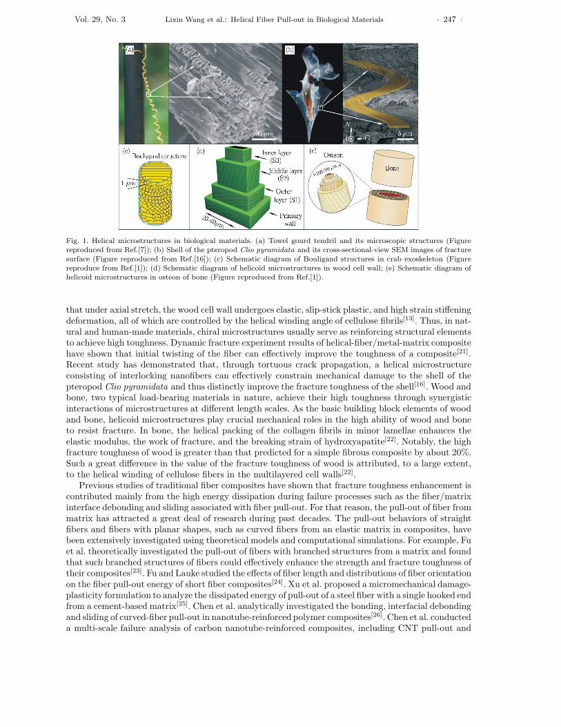
The common building blocks of biological materials or tissues, such as DNA, proteins, and celluloses,usually have intrinsic chirality in their geometric configurations[14]. That means there is an absenceof mirror symmetry of biomacromolecules in these materials, a feature that particularly favors chiralassembly or growth, forming a variety of chiral microstructures, e.g., helical inclusions and twistedarrangements of constitute elements, atmultiple length scales[15].Moreover, some other factors associatedwith growth or assembly, such as inhomogeneous interactions between organic and inorganic componentsand anisotropic physical or chemical environments, can also induce helical or twisted microstructures.Among the intricate microstructures developed in nature, chiral microstructures are perhaps mostpervasive[14] and have attracted significant attention from researchers. Chiral microstructures appearat almost every structural level of biological materials[7,14]. For example, chiral structured motifs existat nano- and microscale, and even in a hierarchical manner, in DNA, wood, tendon, ligament, bone,hoof, and horn, to name just a few. In fact, biological microstructures taking chiral shapes such asthe helix can even be regarded as a unifying structural principle in biology[14]. Several representativechiral microstructures in animal and plant tissues are shown in Fig.1. Figure 1(a) shows that nanoscalecellulose fibril helices, as the building block of tendrils of a towel gourd[7], are contained in the cellwall. Figure 1(b) shows that a chiral stack microstructure is composed of densely packed helical fibrilsin the shell of the pteropod Clio pyramidata[16] . Similar helical or twisted arrangements of mineralrods also occur in the crab exoskeleton, forming the Bouligand structure, as shown in Fig.1(c)[1]. InFig.1(d) it can be seen that the cell wall in wood consists of several cylindrical helicoid layers, each layerbeing made up of a number of cellulose fibrils helically winding in a matrix of hemicellulose and ligninwith different microfibril angles (MFAs)[8,12]. As a unique structural motif, such three-dimensionalmicroscopic helicoid layers are also present in many other biological materials such as bone. Figure 1(e)demonstrates that, like the wood cell wall, the osteon, as the building block of bone, is composed of thehaversian canal and multiple mineral lamellae, in which collagen fiber is helically intercalated with adefinite MFA[1]. At nanoscale, the collagen fiber is a bundle of collagen fibrils in a form of a triple helixstructure, demonstrating a hierarchy of chiral microstructure. In fact, a number of animal and planttissues such as tendons, ligaments, and climbing tendrils are hierarchically structured chiral materials.
Extensive helical or twisted microstructures can not only expertly control the macroscopic morpholo-gies of plant tissues such as climbing tendrils through varying the size and shape of the microstructures[7],but also provide biological materials with a wide range of superior physical and mechanical properties.For example, the helical winding of cellulose or collagen fibrils in the basic building elements endows woodand bone with unusual piezoelectricity; helical nanostructures render the beautiful and brilliant colors ofbutterfly wings[17]. This is because, due to their inherent geometrical chirality, i.e., translation-rotationhelical symmetry, helical or twisted microstructures usually bring a corresponding chirality to certainmaterial properties, a feature normally manifested by the electro-mechanical coupling behavior andthe stretch-twist coupling deformation, etc.[18,19]. Compared to their straight or planar counterparts,chiral microstructures are more extensible and flexible due to their three-dimensional configurationswith uniform curvature and torsion[20]. Furthermore, chiral microstructures often induce a hardeningtype nonlinear constitutive behavior, providing their composites with a relatively high ability of energyabsorption during deformation and rupture[20]. For example, coarse-grained simulation results show
Vol. 29, No. 3 Lixin Wang et al.: Helical Fiber Pull-out in Biological Materials · 247 ·
Fig. 1. Helical microstructures in biological materials. (a) Towel gourd tendril and its microscopic structures (Figurereproduced from Ref.[7]); (b) Shell of the pteropod Clio pyramidata and its cross-sectional-view SEM images of fracturesurface (Figure reproduced from Ref.[16]); (c) Schematic diagram of Bouligand structures in crab exoskeleton (Figurereproduce from Ref.[1]); (d) Schematic diagram of helicoid microstructures in wood cell wall; (e) Schematic diagram ofhelicoid microstructures in osteon of bone (Figure reproduced from Ref.[1]).
that under axial stretch, the wood cell wall undergoes elastic, slip-stick plastic, and high strain stiffeningdeformation, all of which are controlled by the helical winding angle of cellulose fibrils[13]. Thus, in nat-ural and human-made materials, chiral microstructures usually serve as reinforcing structural elementsto achieve high toughness. Dynamic fracture experiment results of helical-fiber/metal-matrix compositehave shown that initial twisting of the fiber can effectively improve the toughness of a composite[21].Recent study has demonstrated that, through tortuous crack propagation, a helical microstructureconsisting of interlocking nanofibers can effectively constrain mechanical damage to the shell of thepteropod Clio pyramidata and thus distinctly improve the fracture toughness of the shell[16]. Wood andbone, two typical load-bearing materials in nature, achieve their high toughness through synergisticinteractions of microstructures at different length scales. As the basic building block elements of woodand bone, helicoid microstructures play crucial mechanical roles in the high ability of wood and boneto resist fracture. In bone, the helical packing of the collagen fibrils in minor lamellae enhances theelastic modulus, the work of fracture, and the breaking strain of hydroxyapatite[22]. Notably, the highfracture toughness of wood is greater than that predicted for a simple fibrous composite by about 20%.Such a great difference in the value of the fracture toughness of wood is attributed, to a large extent,to the helical winding of cellulose fibers in the multilayered cell walls[22].
Previous studies of traditional fiber composites have shown that fracture toughness enhancement iscontributed mainly from the high energy dissipation during failure processes such as the fiber/matrixinterface debonding and sliding associated with fiber pull-out. For that reason, the pull-out of fiber frommatrix has attracted a great deal of research during past decades. The pull-out behaviors of straightfibers and fibers with planar shapes, such as curved fibers from an elastic matrix in composites, havebeen extensively investigated using theoretical models and computational simulations. For example, Fuet al. theoretically investigated the pull-out of fibers with branched structures from a matrix and foundthat such branched structures of fibers could effectively enhance the strength and fracture toughness oftheir composites[23]. Fu and Lauke studied the effects of fiber length and distributions of fiber orientationon the fiber pull-out energy of short fiber composites[24]. Xu et al. proposed a micromechanical damage-plasticity formulation to analyze the dissipated energy of pull-out of a steel fiber with a single hooked endfrom a cement-based matrix[25]. Chen et al. analytically investigated the bonding, interfacial debondingand sliding of curved-fiber pull-out in nanotube-reinforced polymer composites[26]. Chen et al. conducteda multi-scale failure analysis of carbon nanotube-reinforced composites, including CNT pull-out and
· 248 · ACTA MECHANICA SOLIDA SINICA 2016
breakage[27]. Yang et al. investigated the size effects of fiber pull-out[28]. Shi et al. studied the effectsof helically shaped nanotubes on the elastic properties of carbon nanotube-reinforced composites[29].However, the failure process of helicoid microstructures, such as the pull-out of helical or twisted fiber,has not yet been studied, although chiral microstructures exist widely in biological materials and playan important role in achieving high toughness. Compared to straight and planar shaped fibers, helicalfiber shapes usually induce much more complex three-dimensional stress and strain fields, and thus atpresent there are generally no analytical solutions for helical fiber pull-out.
In wood and bone, helicoid microstructures are made up of relatively weak components such ascellulose and lignin or hydroxyapatite and protein molecules, yet they exhibit high toughness. Theirstructural features and mechanical mechanisms therefore have the potential to inspire the developmentof novel materials with enhanced properties. Investigation of such underlying mechanisms or principlesshould foster new understandings of how biological materials assemble weak components at nano- andmicroscale to achieve such high mechanical properties. From a biomimetic point of view, it is criticalto identify the exact underlying mechanisms at nano- and microscale that control the high toughnessof biological materials.
In this paper, we quantitatively investigate the pull-out behavior of a helical fiber from an elasticmatrix using the FEM simulation, with implications for the mechanism underlying the mechanicalreinforcement of helicoid microstructures.
II. FEM Modeling of Helical Fiber Pull-outIn bone and wood, helicoid microstructures such as osteon and wood cell or fiber usually have a large
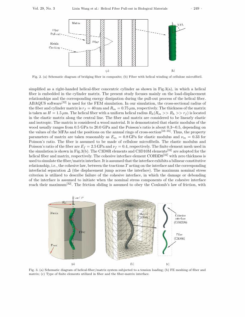
aspect ratio. For example, the length of an osteon or plant cell is of the order of several millimeters,whereas their width is only about several micrometers and even tens of nanometers. Both bone andwood derive their mechanical properties mainly from the basic structural elements, i.e., osteon andplant cell. In this sense, we can simply consider bone and wood as fiber-reinforced composites, althoughthey have complex hierarchical structures. Compared to traditional fiber-reinforced composites, crackpropagation in wood and bone and the corresponding failure processes are much more complex, usuallyinvolving deformation and fracture of microstructures at multiple length scales and their interplay. Thefailure process typically involves deformation and cracking of hierarchical microstructures, debondingof interface between fiber (i.e., osteon and plant cell) and matrix, fiber pull-out and even breakage. Itis noted that fiber pull-out and breakage can occur simultaneously in some cases, depending on theinterface strength, fiber strength, and fiber modulus[30]. Compared to straight fibers, helical fibers canusually tolerate large elongation while still retaining low strain, due to their geometrical shapes. In thispaper, we mainly elaborate on the effects of the helical shape of microstructure on pull-out behaviors,and thus the fiber breakage is not considered. The failure process also includes debonding and frictionalsliding of the interface between the helicoid layers in osteon and wood cell wall. Among these importantfailure mechanisms, fiber/matrix interface debonding and fiber pull-out are considered as the mostsignificant sources of energy dissipation that accounts for the high toughness of bone and wood. Asshown in Fig.2, wood cells are often pulled out from their matrix during the fracture process of wood,serving as bridging elements to transfer stresses between crack faces. The geometrical shape and sizeof bridge elements and their arrangements are, to a large extent, responsible for the tensile and shearstresses and the corresponding energy dissipation in the bridging zone. Therefore, particular attentionis warranted on the way helicoid microstructures contribute to the high toughness of their composites.
In this study we take wood as an example, and conduct the FEM simulation of pull-out behaviors ofhelical fibers, with implications for the underlying mechanism whereby helicoid microstructures enhancethe fracture toughness of biological composites. In our simulation and analysis, we use for simplicity amodel of a composite system for wood. Among the helicoid layers in the wood cell wall, the secondarylayer (i.e., S2 layer) with the greatest thickness is generally considered to be directly responsible for themechanical properties of the cell. Thus, only the S2 layer is considered and other helicoid layers can beneglected, again for simplicity. Takingwoodas a fiber composite[31], the traditional single-fiber concentriccylinder system in which a straight fiber or cell wall is embedded in a cylinder matrix can be used as thecomposite system model in our analysis to represent the wood cell and surrounding matrix material.Considering the fact that the primary structured characteristic of the S2 layer in the fiber or woodcell wall lies in the helical winding of cellulose microfibrils, the composite system model can be further
Vol. 29, No. 3 Lixin Wang et al.: Helical Fiber Pull-out in Biological Materials · 249 ·
Fig. 2. (a) Schematic diagram of bridging fiber in composite; (b) Fiber with helical winding of cellulose microfibril.
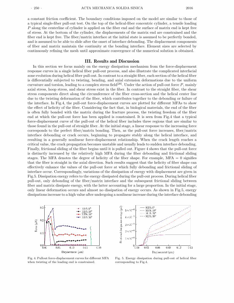
simplified as a right-handed helical-fiber concentric cylinder as shown in Fig.3(a), in which a helicalfiber is embedded in the cylinder matrix. The present study focuses mainly on the load-displacementrelationships and the corresponding energy dissipation during the pull-out process of the helical fiber.ABAQUS software[32] is used for the FEM simulation. In our simulation, the cross-sectional radius ofthe fiber and cylinder matrix is rf = 40 nm and Rm = 0.75 µm, respectively. The thickness of the matrixis taken as H = 1.5 µm. The helical fiber with a uniform helical radius Rh(Rm >> Rh >> rf ) is locatedin the elastic matrix along the central line. The fiber and matrix are considered to be linearly elasticand isotropic. The matrix is considered a wood material. It is demonstrated that elastic modulus of thewood usually ranges from 0.5 GPa to 20.0 GPa and the Poisson’s ratio is about 0.3∼0.5, depending onthe values of the MFAs and the positions on the annual rings of cross-section[33–35]. Thus, the propertyparameters of matrix are taken reasonably as Em = 0.8 GPa for elastic modulus and νm = 0.33 forPoisson’s ratio. The fiber is assumed to be made of cellulose microfibrils. The elastic modulus andPoisson’s ratio of the fiber are Ef = 2.5 GPa and νf = 0.4, respectively. The finite element mesh used inthe simulation is shown in Fig.3(b). The C3D8R elements and C3D10M elements[32] are adopted for thehelical fiber and matrix, respectively. The cohesive interface element COH3D8[32] with zero thickness isused to simulate the fiber/matrix interface. It is assumed that the interface exhibits a bilinear constitutiverelationship, i.e., the cohesive law, between the tractions T acting on the interface and the correspondinginterfacial separation ∆ (the displacement jump across the interface). The maximum nominal stresscriterion is utilized to describe failure of the cohesive interface, in which the damage or debondingof the interface is assumed to initiate when the nominal stress components of the cohesive interfacereach their maximum[32]. The friction sliding is assumed to obey the Coulomb’s law of friction, with
Fig. 3. (a) Schematic diagram of helical-fiber/matrix system subjected to a tension loading; (b) FE meshing of fiber andmatrix; (c) Type of finite elements utilized in fiber and the fiber-matrix interface.
· 250 · ACTA MECHANICA SOLIDA SINICA 2016
a constant friction coefficient. The boundary conditions imposed on the model are similar to those ofa typical single-fiber pull-out test. On the top of the helical-fiber concentric cylinder, a tensile loadingP along the centerline of cylinder is applied on the fiber end and the surface of matrix end is kept freeof stress. At the bottom of the cylinder, the displacements of the matrix end are constrained and thefiber end is kept free. The fiber/matrix interface at the initial state is assumed to be perfectly bonded,and is assumed to be able to slide after the onset of interface debonding. The displacement componentsof fiber and matrix maintain the continuity at the bonding interface. Element sizes are selected bycontinuously refining the mesh until approximate convergence of the numerical solution is obtained.
III. Results and DiscussionIn this section we focus mainly on the energy dissipation mechanism from the force-displacement
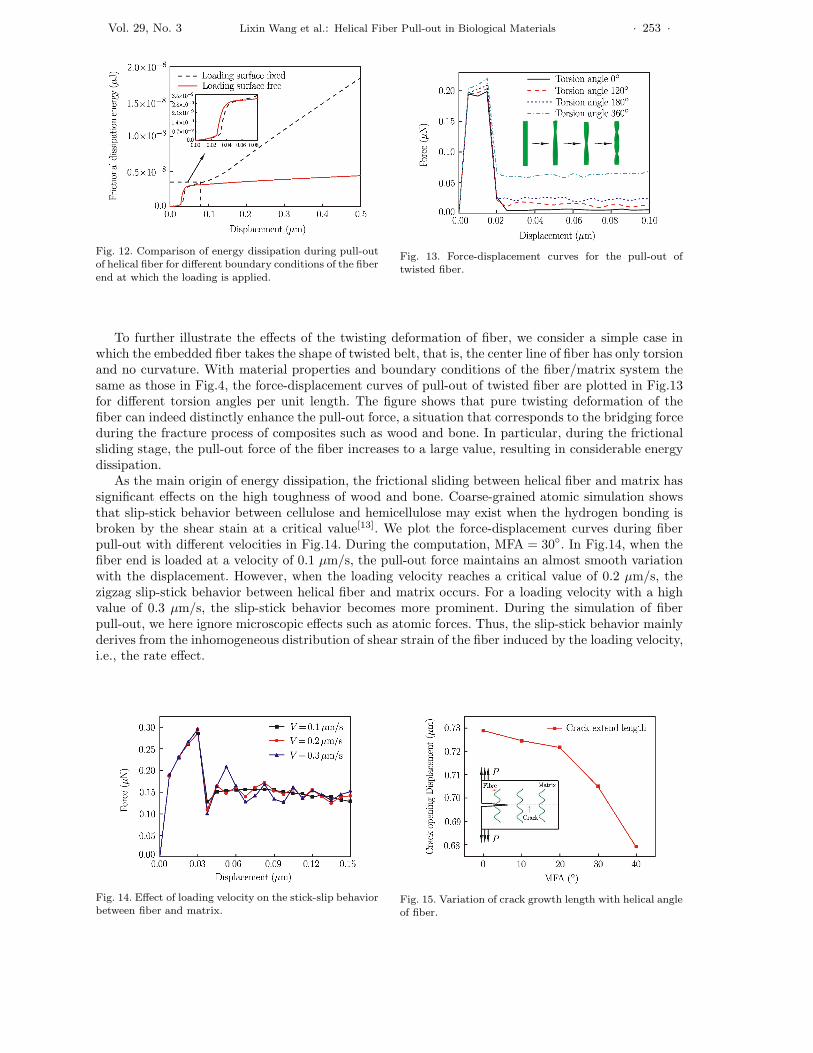
response curves in a single helical fiber pull-out process, and also illustrate the complicated interfacialzone evolution during helical fiber pull-out. In contrast to a straight fiber, each section of the helical fiberis differentially subjected to twisting, bending, and axial extension deformations due to the uniformcurvature and torsion, leading to a complex stress field[20]. Under the action of pull-out force P , mainlyaxial stress, hoop stress, and shear stress exist in the fiber. In contrast to the straight fiber, the shearstress components direct along the circumference of the fiber cross-section and the helical center linedue to the twisting deformation of the fiber, which contributes together to the debonding or failure ofthe interface. In Fig.4, the pull-out force-displacement curves are plotted for different MFAs to showthe effect of helicity of the fiber. Considering the fact that, in biological materials, the end of the fiberis often fully bonded with the matrix during the fracture process, the twisting freedom of the fiberend at which the pull-out force has been applied is constrained. It is seen from Fig.4 that a typicalforce-displacement curve of the pull-out of the helical fiber includes three regions that are similar tothose found in the pull-out of straight fiber. At the initial stage, a linear response to the increasing forcecorresponds to the perfect fiber/matrix bonding. Then, as the pull-out force increases, fiber/matrixinterface debonding or crack occurs, beginning to propagate stably along the helical interface, andresulting in a generally nonlinear force-displacement relationship. When the crack length reaches acritical value, the crack propagation becomes unstable and usually leads to sudden interface debonding.Finally, frictional sliding of the fiber begins until it is pulled out. Figure 4 shows that the pull-out forceis distinctly increased by the relatively high MFA during the fiber debonding and frictional slidingstages. The MFA denotes the degree of helicity of the fiber shape. For example, MFA = 0 signifiesthat the fiber is straight in the axial direction. Such results suggest that the helicity of fiber shape caneffectively enhance the values of the pull-out force at which fully debonding and frictional sliding ofinterface occur. Correspondingly, variations of the dissipation of energy with displacement are given inFig.5. Dissipation energy refers to the energy dissipated during the pull-out process. During helical fiberpull-out, only debonding of the fiber/matrix interface and the subsequent frictional sliding betweenfiber and matrix dissipate energy, with the latter accounting for a large proportion. In the initial stage,only linear deformation occurs and almost no dissipation of energy occurs. As shown in Fig.5, energydissipations increase to a high value after undergoing a nonlinear increase during the interface debonding
Fig. 4. Pullout force-displacement curves for different MFAwhen twisting of the loading end is constrained.
Fig. 5. Energy dissipation during pull-out of helical fibercorresponding to Fig.4.

Vol. 29, No. 3 Lixin Wang et al.: Helical Fiber Pull-out in Biological Materials · 251 ·
Fig. 6. Pull-out force-displacement curves for differentMFAs and the same fiber length.
Fig. 7. Energy dissipation during pull-out of helical fibercorresponding to Fig.6.
stage and a linear increase during the frictional sliding stage. This is because frictional sliding obeysthe Coulomb friction law and thus the corresponding linear energy dissipation depends on the slidinglength. Obviously, compared to the straight shape, a helical shape with large MFA usually results inmuch higher values of pull-out force and energy dissipation. It should be noted that the fibers consideredin Figs.4 and 5 corresponding to the plotted curves that have different MFAs and fiber lengths andthe same helical radius, implying that these composite systems have different fiber volume percentages(FVPs). To further illustrate the effects of MFA, we also plot the force-displacement curves shown inFig.6 and the variation curves of energy dissipation shown in Fig.7 in the case that the consideredcomposite systems have the same FVP, that is, only the MFA varies and the fiber length is unchanged.The FVP of the composite system with a straight fiber can be defined as V s
f = r2f/R2
m and with a helical
fiber as V hf =
πr2fL
πR2mL sinα
= r2f/(R2
m sinα), in which the helical angle α = 90◦−MFA and L denotes the
fiber length. This definition shows that the FVP of the helical fiber depends on the fiber cross-sectionradius, the matrix cross-section radius, and the helical angle. When the FVP is fixed, the values of fiberradius can be determined if the value of MFA is given. For a helix, the fiber length can be expressedas L = 2nπRh/cosα, in which n denotes the coil number and the helical angle α = 90◦ − MFA. Thegeometrical configuration (e.g. helical radius) of fiber helices with a fixed length and one coil can alsobe determined for a definite value of MFA. The fiber length is taken as L = 1.73 µm. Figures 6 and 7show that a higher MFA can result in higher values of both pull-out force and energy dissipation, whichare similar to those in Figs.4 and 5. These results in Figs.4-7 indicate that the MFA of the fiber caneffectively control the values of pull-out force energy dissipation. It should be noted that in wood, MFAvalues generally range from zero to 45◦. On the one hand, the uniform curvature and torsion of thehelical center line of the fiber induce a combination of the axial shear stress along the center line andthe circumferential shear stress of the fiber cross-section, which generates a much higher pull-out forcethan that of the straight fiber. On the other hand, helices have been proved to be the optimal shapeadopted by long thin strings such as DNA and folded polymeric chains to achieve the greatest length orthe highest compact density in a limited space[36]. Similarly, the helical shape also leads to the greatestlength of fiber as well as the largest interface area for the helical-fiber/matrix system with a specifiedthickness. Thus, the combination of these two sides induced by the helical shape of the fiber results inenergy dissipation during fiber pull-out that is much higher, even several times greater than that in astraight-fiber/matrix cylinder system. In fiber composites, the energy dissipation of fiber pull-out is themain contributor to the toughness of the composite. Therefore, the helical shape of a fiber at microscalecan be considered as one of the main sources of the high toughness of wood and bone. That tougheningmechanism of helical fibers at microscale can effectively explain the aforementioned great differencebetween the real value of the fracture toughness of wood and its predicted value using a simple fibrouscomposite model.
Figure 8 illustrates the effects of fiber length on the force-displacement relationship of the fiber pull-out. During the computation, the MFA is fixed at 30◦. The parameters of fiber and matrix propertiesare taken as those from Fig.4. It is shown that at the fully bonded stage, the fiber length has no distinct

· 252 · ACTA MECHANICA SOLIDA SINICA 2016
Fig. 8. Pull-out force-displacement curves for different fiberlengths and different MFAs.
Fig. 9. Energy dissipation during pull-out of helical fibercorresponding to Fig.8.
effect on the pull-out behavior. However, the fiber/matrix interface debonding force and the frictionforce clearly increase with the increase of fiber length. Correspondingly, the energy dissipation duringthese two stages can also be affected by fiber length, as shown in Fig.9. This phenomenon suggeststhat an increase in fiber length can directly increase the interface area, and in turn, increases boththe debonding force and the dissipated energy. Moreover, the size of the fiber cross-section can alsodistinctly influence fiber pull-out behaviors. In Fig.10, the force-displacement curves for different fiberradii are plotted. We take MFA = 30◦ and rf = 40 nm. It can be found that the force during thepull-out process can be effectively increased by increasing the cross-section size. Because the FVPs ofthe composite systems under consideration are directly proportional to the MFA and fiber cross-sectionradius for the same fiber length, the results in Fig.10 in fact show that the effects of FVP on the pull-outbehavior are similar to those of fiber cross-section.
Figure 11 shows the force-displacement curves for different MFAs, in which the loading end of fibercan twist freely during fiber pull-out. Except for the boundary condition of the fiber loading end, thegeometrical properties and parameters of the helical-fiber/matrix system are given the same valuesas those in Fig.4. The force-displacement curves exhibit similar three-domain behavior to those inFig.4. However, the values of pull-out forces at which the fiber/matrix interface begins debonding, fullydebonding and frictional sliding are much lower. Furthermore, the frictional sliding behaviors seem lesssensitive to the value of the MFA of helical fiber than those exhibited by the curves in Fig.4. This isbecause the boundary condition of free twisting at the loading end leads to a considerable release of thetwist strain of the fiber. The energy dissipation curves of the fiber/matrix system during fiber pull-outin the cases of two boundary conditions at the loading end are also plotted in Fig.12. The value of MFAis taken as 30◦. The plots show that a fixed boundary condition at the loading end can induce muchgreater energy dissipation than that resulting from the free boundary condition. This finding indicatesthat the twisting deformation of the fiber plays an important role in the high toughness of wood andbone.
Fig. 10. Pull-out force-displacement curves for differentfiber cross-section radii and the same fiber length.
Fig. 11. Pull-out force-displacement curves for differentMFAs when twisting of the loading end is not constrained.
Vol. 29, No. 3 Lixin Wang et al.: Helical Fiber Pull-out in Biological Materials · 253 ·
Fig. 12. Comparison of energy dissipation during pull-outof helical fiber for different boundary conditions of the fiberend at which the loading is applied.
Fig. 13. Force-displacement curves for the pull-out oftwisted fiber.
To further illustrate the effects of the twisting deformation of fiber, we consider a simple case inwhich the embedded fiber takes the shape of twisted belt, that is, the center line of fiber has only torsionand no curvature. With material properties and boundary conditions of the fiber/matrix system thesame as those in Fig.4, the force-displacement curves of pull-out of twisted fiber are plotted in Fig.13for different torsion angles per unit length. The figure shows that pure twisting deformation of thefiber can indeed distinctly enhance the pull-out force, a situation that corresponds to the bridging forceduring the fracture process of composites such as wood and bone. In particular, during the frictionalsliding stage, the pull-out force of the fiber increases to a large value, resulting in considerable energydissipation.
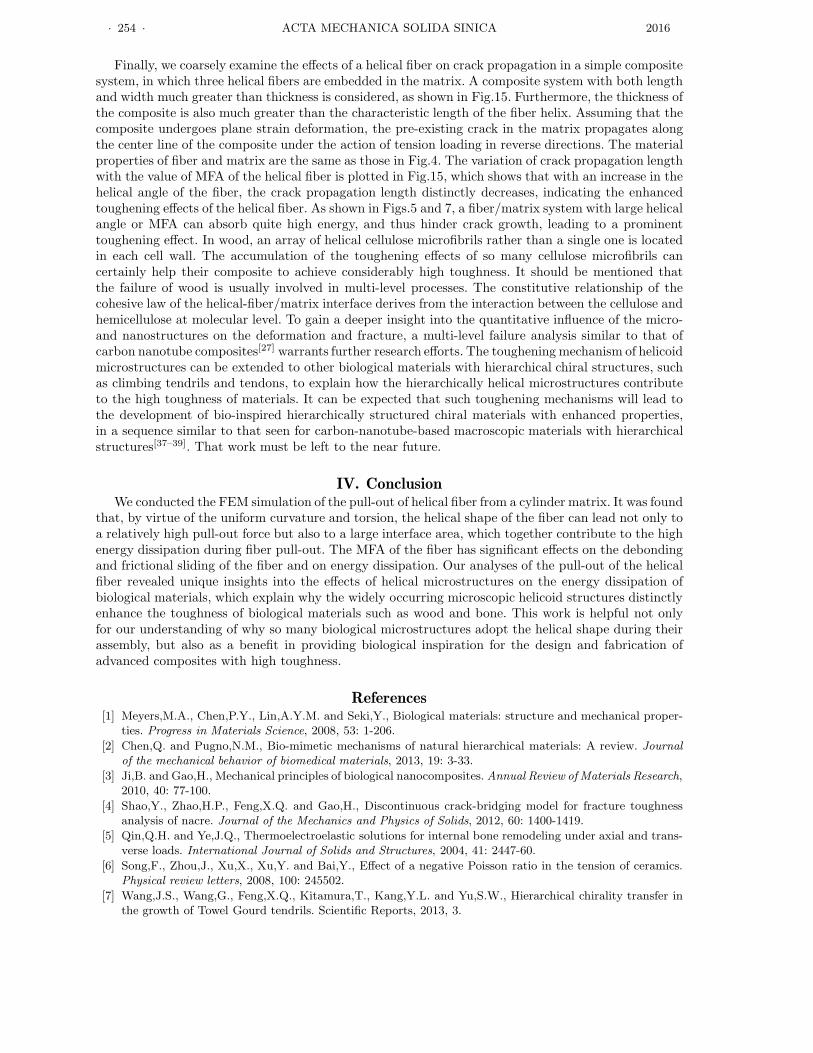
As the main origin of energy dissipation, the frictional sliding between helical fiber and matrix hassignificant effects on the high toughness of wood and bone. Coarse-grained atomic simulation showsthat slip-stick behavior between cellulose and hemicellulose may exist when the hydrogen bonding isbroken by the shear stain at a critical value[13]. We plot the force-displacement curves during fiberpull-out with different velocities in Fig.14. During the computation, MFA = 30◦. In Fig.14, when thefiber end is loaded at a velocity of 0.1 µm/s, the pull-out force maintains an almost smooth variationwith the displacement. However, when the loading velocity reaches a critical value of 0.2 µm/s, thezigzag slip-stick behavior between helical fiber and matrix occurs. For a loading velocity with a highvalue of 0.3 µm/s, the slip-stick behavior becomes more prominent. During the simulation of fiberpull-out, we here ignore microscopic effects such as atomic forces. Thus, the slip-stick behavior mainlyderives from the inhomogeneous distribution of shear strain of the fiber induced by the loading velocity,i.e., the rate effect.
Fig. 14. Effect of loading velocity on the stick-slip behaviorbetween fiber and matrix.
Fig. 15. Variation of crack growth length with helical angleof fiber.
· 254 · ACTA MECHANICA SOLIDA SINICA 2016
Finally, we coarsely examine the effects of a helical fiber on crack propagation in a simple compositesystem, in which three helical fibers are embedded in the matrix. A composite system with both lengthand width much greater than thickness is considered, as shown in Fig.15. Furthermore, the thickness ofthe composite is also much greater than the characteristic length of the fiber helix. Assuming that thecomposite undergoes plane strain deformation, the pre-existing crack in the matrix propagates alongthe center line of the composite under the action of tension loading in reverse directions. The materialproperties of fiber and matrix are the same as those in Fig.4. The variation of crack propagation lengthwith the value of MFA of the helical fiber is plotted in Fig.15, which shows that with an increase in thehelical angle of the fiber, the crack propagation length distinctly decreases, indicating the enhancedtoughening effects of the helical fiber. As shown in Figs.5 and 7, a fiber/matrix system with large helicalangle or MFA can absorb quite high energy, and thus hinder crack growth, leading to a prominenttoughening effect. In wood, an array of helical cellulose microfibrils rather than a single one is locatedin each cell wall. The accumulation of the toughening effects of so many cellulose microfibrils cancertainly help their composite to achieve considerably high toughness. It should be mentioned thatthe failure of wood is usually involved in multi-level processes. The constitutive relationship of thecohesive law of the helical-fiber/matrix interface derives from the interaction between the cellulose andhemicellulose at molecular level. To gain a deeper insight into the quantitative influence of the micro-and nanostructures on the deformation and fracture, a multi-level failure analysis similar to that ofcarbon nanotube composites[27] warrants further research efforts. The toughening mechanism of helicoidmicrostructures can be extended to other biological materials with hierarchical chiral structures, suchas climbing tendrils and tendons, to explain how the hierarchically helical microstructures contributeto the high toughness of materials. It can be expected that such toughening mechanisms will lead tothe development of bio-inspired hierarchically structured chiral materials with enhanced properties,in a sequence similar to that seen for carbon-nanotube-based macroscopic materials with hierarchicalstructures[37–39]. That work must be left to the near future.
IV. ConclusionWe conducted the FEM simulation of the pull-out of helical fiber from a cylinder matrix. It was found
that, by virtue of the uniform curvature and torsion, the helical shape of the fiber can lead not only toa relatively high pull-out force but also to a large interface area, which together contribute to the highenergy dissipation during fiber pull-out. The MFA of the fiber has significant effects on the debondingand frictional sliding of the fiber and on energy dissipation. Our analyses of the pull-out of the helicalfiber revealed unique insights into the effects of helical microstructures on the energy dissipation ofbiological materials, which explain why the widely occurring microscopic helicoid structures distinctlyenhance the toughness of biological materials such as wood and bone. This work is helpful not onlyfor our understanding of why so many biological microstructures adopt the helical shape during theirassembly, but also as a benefit in providing biological inspiration for the design and fabrication ofadvanced composites with high toughness.
References[1] Meyers,M.A., Chen,P.Y., Lin,A.Y.M. and Seki,Y., Biological materials: structure and mechanical proper-
ties. Progress in Materials Science, 2008, 53: 1-206.
[2] Chen,Q. and Pugno,N.M., Bio-mimetic mechanisms of natural hierarchical materials: A review. Journal
of the mechanical behavior of biomedical materials, 2013, 19: 3-33.
[3] Ji,B. and Gao,H., Mechanical principles of biological nanocomposites. Annual Review of Materials Research,2010, 40: 77-100.
[4] Shao,Y., Zhao,H.P., Feng,X.Q. and Gao,H., Discontinuous crack-bridging model for fracture toughnessanalysis of nacre. Journal of the Mechanics and Physics of Solids, 2012, 60: 1400-1419.
[5] Qin,Q.H. and Ye,J.Q., Thermoelectroelastic solutions for internal bone remodeling under axial and trans-verse loads. International Journal of Solids and Structures, 2004, 41: 2447-60.
[6] Song,F., Zhou,J., Xu,X., Xu,Y. and Bai,Y., Effect of a negative Poisson ratio in the tension of ceramics.Physical review letters, 2008, 100: 245502.
[7] Wang,J.S., Wang,G., Feng,X.Q., Kitamura,T., Kang,Y.L. and Yu,S.W., Hierarchical chirality transfer inthe growth of Towel Gourd tendrils. Scientific Reports, 2013, 3.
Vol. 29, No. 3 Lixin Wang et al.: Helical Fiber Pull-out in Biological Materials · 255 ·
[8] Fratzl,P., Biomimetic materials research: what can we really learn from nature’s structural materials?Journal of the Royal Society Interface, 2007, 4: 637-42.
[9] Sanchez,C., Arribart,H. and Guille,M.M.G., Biomimetism and bioinspiration as tools for the design ofinnovative materials and systems. Nature materials, 2005, 4: 277-88.
[10] Zheng,Q.S., Yu,Y. and Feng,X.Q., The role of adaptive-deformation of water strider leg in its walking onwater. Journal of Adhesion Science and Technology, 2009, 23: 493-501.
[11] Kong,X., Liu,J., Zhang,W. and Qu,Y., Load-bearing ability of the mosquito tarsus on water surfaces arisingfrom its flexibility. AIP Advances, 2015 ,5: 037101.
[12] Neville,A.C., Biology of Fibrous Composites: Development beyond the Cell Membrane. Cambridge Uni-versity Press, 1993.
[13] Adler,D.C. and Buehler,M.J., Mesoscale mechanics of wood cell walls under axial strain. Soft Matter, 2013,9: 7138-7144.
[14] Galloway.,J., Helical imperative: paradigm of growth, form and function. eLS, 2010: 1-11.
[15] Grason,G.M., Braided bundles and compact coils: The structure and thermodynamics of hexagonally packedchiral filament assemblies. Physical Review E, 2009, 79: 041919.
[16] Li,L., Weaver,J.C. and Ortiz,C., Hierarchical structural design for fracture resistance in the shell of thepteropod Clio pyramidata. Nature communications, 2015, 6: 6216.
[17] Turner,M.D., Saba,M., Zhang,Q., Cumming,B.P., Schroder-Turk,G.E. and Gu,M., Miniature chiral beam-splitter based on gyroid photonic crystals. Nature Photonics, 2013, 7: 801-805.
[18] Lakes,R.S. and Benedict,R.L., Noncentrosymmetry in micropolar elasticity. International Journal of En-
gineering Science, 1982, 20: 1161-1167.
[19] Sharma,P., Size-dependent elastic fields of embedded inclusions in isotropic chiral solids. International
Journal of Solids and structures, 2004, 41: 6317-6333.
[20] Slepyan,L., Krylov,V and Parnes,R., Helical inclusion in an elastic matrix. Journal of the Mechanics and
Physics of Solids, 2000, 48: 827-865.[21] Kagawa,Y., Nakata,E. and Yoshida,S., Fracture behavior and toughness of helical fiber reinforced composite
metals. In: Progress in Science and Engineering of Composites. ICCM-IV, Tokyo, 1982: 1457-1464.[22] Ball,P., Materials of the Future. In: UNESCO Encyclopedia of Life Support Systems, 2001.
[23] Fu,S.Y., Zhou,B.L. and Lung,C.W., On the pull-out of fibres with branched structure and the interface ofstrength and fracture toughness of composite. Composites Science and Technology, 1993, 47: 245-250.
[24] Fu,S.Y. and Lauke,B., The fibre pull-out energy of misaligned short fibre reinforced polymers. Journal of
Materials Science, 1997, 32: 1985-1993.[25] Xu,B.W., Ju,J.W. and Shi,H.S., Progressive micromechanical modeling for pullout energy of hooked-end
steel fiber in cement-based composites. Internal Journal of Damage and Mechanics, 2011, 20: 922-938.[26] Chen,X.Y., Beyerlein,J.I. and Brinson,L.C., Curved-fiber pull-out model for nanocomposites. Part 2: In-
terface debonding and sliding. Mechanics of Materials, 2009, 41: 293-307.
[27] Chen,Y.L., Liu,B., He,X.Q., Hung,Y. and Hwang,K.C., Failure analysis and the optimal toughness designof carbon nanotube-reinforced composites. Composites Science and Technology, 2010, 70: 1360-1367.
[28] Yang,Q.S., Qin,Q.H. and Peng,X.R., Size effects in the fiber pullout test. Composite Structures, 2003, 61:193-198.
[29] Shi,D.L., Feng,X.Q., Huang,Y., Huang,K.C. and Gao,H.J., The effect of nanotube waviness and agglomer-ation on the elastic property of carbon nanotube-reinforced composites. Journal of Engineering Materials
and Technology, 2004, 126: 250-257.
[30] Goh,K.L., Aspden,R.M. and Hukins,D.W.L., Review: finite element analysis of sterss transfer in short-fibrecomposite materials. Composites Science and Technology, 2004, 64: 1091-1100.
[31] Marklund,E. and Varna,J., Modeling the effect of helical fiber structure on wood fiber composite elasticproperties. Applied Composite Materials, 2009, 16: 245-262.
[32] ABAQUS, Hibbitt Karlsson Sorenson, Inc., 1997.
[33] Stefanie,E., Microstructure and fracture mechanical response of wood. International Journal of Fracture,2006, 139: 495-508.
[34] Reiterer,A., Lichtenegger,H., Tschegg,S. and Fratzl,P., Experimental evidence for a mechanical functionof the cellulose microfibril angle in wood cell walls. Philosophical Magazine A, 1999, 79: 2173-2184.
[35] Wang,Z., Gu,L.L., Gao,Z.Z., Liu,B. and Wang,Y.L., Experimental study on Poisson’s ratio of lumber bydynamic testing. Chinese Journal of Scientia Silvae Sinicae, 2015, 51: 102-107.
[36] Maritan,A., Micheletti,C., Trovato,A. and Banavar,J.R., Optimal shapes of compact strings. Nature, 2000,406: 287-290.
[37] Li,Q., Kang,Y.L., Qiu,W., Deng,W.L. and Zhong,X.H., Deformation mechanisms of carbon nanotube fibersunder tensile loading by insitu Raman spectroscopy analysis. Nanotechnology, 2011, 22: 225704.

· 256 · ACTA MECHANICA SOLIDA SINICA 2016
[38] Qiu,W., Li,Q., Lei,Z.K., Deng,W.L. and Kang,Y.L., The use of a carbon nanotube sensor for measuringstrain by micro-Raman spectrosopy. Carbon, 2013, 53: 161-168.
[39] Deng,W.L., Qiu,W., Li,Q., Li,Y.L. and Han,S.S., Multi-scale experiments and interfacial mechanical mod-eling of carbon nanotube fiber. Experimental Mechanics, 2014, 54: 3-10.