helically coiled heat exchangers - intech -...
TRANSCRIPT
12
Helically Coiled Heat Exchangers
J. S. Jayakumar Professor, Dept. of Mechanical Engineering,
Amrita Vishwa Vidyapeetham, Amrita School of Engineering, Amritapuri, Kollam,
India
1. Introduction
It has been widely reported in literature that heat transfer rates in helical coils are higher as compared to those in straight tubes. Due to the compact structure and high heat transfer coefficient, helical coil heat exchangers find extensive use in industrial applications such as power generation, nuclear industry, process plants, heat recovery systems, refrigeration, food industry, etc. (Abdulla 1994; Bai et al. 1999; Futagami and Aoyama 1988; Jensen and Bergles 1981; Patankar et al. 1974; Xin et al., 1996). Heat exchanger with helical coils is used for residual heat removal systems in islanded or barge mounted nuclear reactor systems, wherein nuclear energy is utilised for desalination of seawater (Manna et al., 1998). The performance of the residual heat removal system, which uses a helically coiled heat exchanger, for various process parameters was investigated by Jayakumar and Grover (1997). The work had been extended to find out the stability of operation of such a system when the barge on which it is mounted is moving (Jayakumar, 1999; Jayakumar et al., 2002).
1.1 Terminology of helically coiled pipes
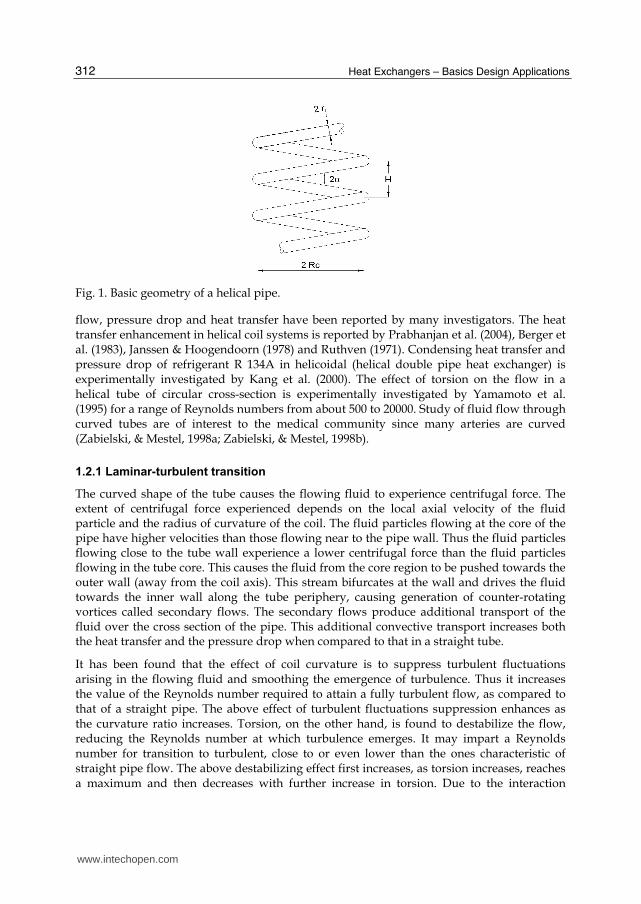
Fig. 1 gives the schematic of the helical coil. The pipe has an inner diameter 2r. The coil diameter is represented by 2RC (measured between the centres of the pipes). The distance between two adjacent turns, called pitch is H. The coil diameter is also called as pitch circle
diameter (PCD). The ratio of pipe diameter to coil diameter (r/Rc) is called curvature ratio, . The ratio of pitch to developed length of one turn (H/2 Rc) is termed non-dimensional pitch, . Consider the projection of the coil on a plane passing through the axis of the coil. The angle, which projection of one turn of the coil makes with a plane perpendicular to the
axis, is called the helix angle, . Consider any cross section of the pipe created by a plane passing through the coil axis. The side of pipe wall nearest to the coil axis is termed inner side of the coil and the farthest side is termed as outer side of the coil. Similar to Reynolds number for flow in pipes, Dean number is used to characterise the flow in a helical pipe.
1.2 Review of single-phase flow and heat transfer
Heat transfer and flow through a curved tube is comprehensively first reviewed by Berger et al. (1983) and subsequently by Shah and Joshi (1987). The latest review of flow and heat transfer characteristics is provided by Naphon & Wongwises (2006). The characteristics of
www.intechopen.com
Heat Exchangers – Basics Design Applications
312
Fig. 1. Basic geometry of a helical pipe.
flow, pressure drop and heat transfer have been reported by many investigators. The heat transfer enhancement in helical coil systems is reported by Prabhanjan et al. (2004), Berger et al. (1983), Janssen & Hoogendoorn (1978) and Ruthven (1971). Condensing heat transfer and pressure drop of refrigerant R 134A in helicoidal (helical double pipe heat exchanger) is experimentally investigated by Kang et al. (2000). The effect of torsion on the flow in a helical tube of circular cross-section is experimentally investigated by Yamamoto et al. (1995) for a range of Reynolds numbers from about 500 to 20000. Study of fluid flow through curved tubes are of interest to the medical community since many arteries are curved (Zabielski, & Mestel, 1998a; Zabielski, & Mestel, 1998b).
1.2.1 Laminar-turbulent transition
The curved shape of the tube causes the flowing fluid to experience centrifugal force. The extent of centrifugal force experienced depends on the local axial velocity of the fluid particle and the radius of curvature of the coil. The fluid particles flowing at the core of the pipe have higher velocities than those flowing near to the pipe wall. Thus the fluid particles flowing close to the tube wall experience a lower centrifugal force than the fluid particles flowing in the tube core. This causes the fluid from the core region to be pushed towards the outer wall (away from the coil axis). This stream bifurcates at the wall and drives the fluid towards the inner wall along the tube periphery, causing generation of counter-rotating vortices called secondary flows. The secondary flows produce additional transport of the fluid over the cross section of the pipe. This additional convective transport increases both the heat transfer and the pressure drop when compared to that in a straight tube.
It has been found that the effect of coil curvature is to suppress turbulent fluctuations arising in the flowing fluid and smoothing the emergence of turbulence. Thus it increases the value of the Reynolds number required to attain a fully turbulent flow, as compared to that of a straight pipe. The above effect of turbulent fluctuations suppression enhances as the curvature ratio increases. Torsion, on the other hand, is found to destabilize the flow, reducing the Reynolds number at which turbulence emerges. It may impart a Reynolds number for transition to turbulent, close to or even lower than the ones characteristic of straight pipe flow. The above destabilizing effect first increases, as torsion increases, reaches a maximum and then decreases with further increase in torsion. Due to the interaction
www.intechopen.com
Helically Coiled Heat Exchangers
313
between turbulence emergence and curvature effects, the same Reynolds number flow may present an equal or even a lower hydraulic resistance in a curved channel than it does in a straight one. Apparently, the reducing effect of curvature on friction, due to the smoothing of turbulence emergence, equals, or even overcomes, the increasing effect due to the secondary flow. But in practical applications, due to layout and economic considerations, the value of torsion is never reaches an effect of destabilization of flow and hence reduction in value of critical Reynolds number.
Another important phenomena observed in helical tubes is the relamianrization. The fluid flow, which was originally turbulent, changes to laminar while flowing inside a helical pipe. This has been experimentally demonstrated by Sreenivasan and Strykowski (1983). The experiment was conducted using a pipe of diameter 19.1 mm wound to form a coil of 90 mm. In the experiment, dye streak introduced at two locations, viz., into the straight section upstream of the coil and into the fourth turn of the coil. It has been observed that the dye introduced in the straight section diffuses rapidly, indicating that the flow there is turbulent. While the dye injected into the fourth turn remains perfectly unruffled for a long distance, indicating the laminar state of the flow in the helical coil.
1.2.2 Critical Reynolds number
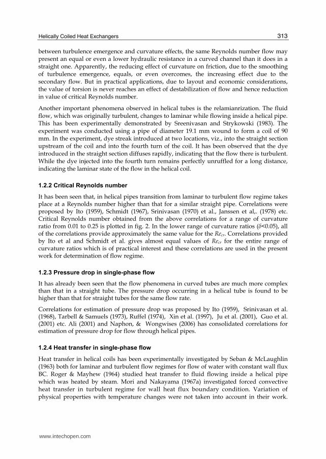
It has been seen that, in helical pipes transition from laminar to turbulent flow regime takes place at a Reynolds number higher than that for a similar straight pipe. Correlations were proposed by Ito (1959), Schmidt (1967), Srinivasan (1970) et al., Janssen et al,. (1978) etc. Critical Reynolds number obtained from the above correlations for a range of curvature ratio from 0.01 to 0.25 is plotted in fig. 2. In the lower range of curvature ratios (├<0.05), all of the correlations provide approximately the same value for the Recr. Correlations provided by Ito et al and Schmidt et al. gives almost equal values of Recr for the entire range of curvature ratios which is of practical interest and these correlations are used in the present work for determination of flow regime.
1.2.3 Pressure drop in single-phase flow
It has already been seen that the flow phenomena in curved tubes are much more complex than that in a straight tube. The pressure drop occurring in a helical tube is found to be higher than that for straight tubes for the same flow rate.
Correlations for estimation of pressure drop was proposed by Ito (1959), Srinivasan et al. (1968), Tarbell & Samuels (1973), Ruffel (1974), Xin et al. (1997), Ju et al. (2001), Guo et al. (2001) etc. Ali (2001) and Naphon, & Wongwises (2006) has consolidated correlations for estimation of pressure drop for flow through helical pipes.
1.2.4 Heat transfer in single-phase flow
Heat transfer in helical coils has been experimentally investigated by Seban & McLaughlin (1963) both for laminar and turbulent flow regimes for flow of water with constant wall flux BC. Roger & Mayhew (1964) studied heat transfer to fluid flowing inside a helical pipe which was heated by steam. Mori and Nakayama (1967a) investigated forced convective heat transfer in turbulent regime for wall heat flux boundary condition. Variation of physical properties with temperature changes were not taken into account in their work.
www.intechopen.com
Heat Exchangers – Basics Design Applications
314
Fig. 2. Critical Reynolds number predicted by various correlations.
Mori and Nakayama (1967b) subsequently studied heat transfer under constant wall temperature boundary condition for the same helical coils. They had observed that the Nusselt number is remarkably affected by a secondary flow due to curvature. They had stated that the same formula used for estimation of heat transfer rates in wall flux boundary conditions can be used for the wall temperature boundary condition as well. Heat transfer and pressure drop in helical pipes was studied by Yildiz et al. (1997).
CFD study of helically coiled double pipe heat exchangers for laminar flow situations were
carried out by Rennie and Raghavan (2005, 2006a). They have modelled the heat transfer
from hot fluid to cold fluid using the CFD package PHOENICS 3.3 and found out the overall
heat transfer coefficients for counter current and parallel flows. Pressure drop and heat
transfer in tube-in-tube helical heat exchanger under turbulent flow conditions was studied
by Vimal Kumar et al. (2006) using the CFD package FLUENT 6. However, no correlation
for estimation of Nu was given in these papers.
Goering et al. (1997) has studied fully developed laminar convective heat transfer in curved
pipes to investigate the dual influence of curvature and buoyancy. Direct numerical study
on influence of curvature and torsion on turbulent flow in a helical pipe has been provided
by Hüttl and Friedrich (2000). Later Hüttl and Friedrich (2001) have conducted a DNS study
to bring out the details of the secondary flow in such systems. Recently Jayakumar et al.
(2008a) have developed a correlation for estimation of inside heat transfer coefficient for
flow of single-phase water through helically coiled heat exchangers. The correlation, which
is validated against experiments, is applicable to a specific configuration of helical coil.
1.3 Pressure drop and heat transfer for air-water two-phase flow
Akagawa et al. (1971) measured pressure drop for two-phase gas liquid flow in helically coiled tubes for different curvature ratios. Kasturi & Stepanek (1972) carried out pressure
www.intechopen.com
Helically Coiled Heat Exchangers
315
drop and void fraction measurement for two-phase counter current flow of gas and liquid in a helical coil. They compared the results with Lockhart-Martinelli correlation, Dukler's correlation and Hughmark's correlation and suggested that Lockhart-Martinelli parameter could be modified to obtain a better correlation. In their later work, Stepanek & Kasturi (1972) proposed correlations for void fraction and pressure drop in terms of new correlating parameters. Flow of air-water mixture through a helically coiled tube was studied by Whalley (1980) and the flow pattern transition between stratified and annular flow was examined. Rangacharyulu and Davies (1984) experimentally studied pressure drop and hold-up for counter-current upward flow of air-liquid system through copper coils. They proposed a new correlation for two-phase frictional pressure drop based on the modified Lockhart-Martinelli parameter. Flow of two-phase air-water mixture in helically coiled tube was studied by Watanabe et al. (1993). They found out the thickness of water film on the wall of the coil at different points around the circumference experimentally.
Czop et al. (1994) carried out experiments on water-SF6 flow through a helically coiled tube of 19.8 mm id with 1170 mm coil diameter. It has been observed that the two-phase pressure drops are very much different from those calculated with Lockhart-Martinelli correlation but are in fairly good agreement with the Chisholm correlation. Awwad et al. (1995) carried out experimental investigations of air-water two-phase flow in horizontal helicoidal pipes. They have found that the pressure drop multiplier is strongly related to superficial velocities of air and water. The helix angle has almost no effect on pressure drop, even though coil diameter has certain effects at low flow rates. Xin et al. (1996) measured the pressure drop and void fraction for an air-water mixture flowing through vertical helicoidal pipes. In their later work, Xin et al. (1997) investigated the effect of coil geometries and flow rates of air and water on two-phase flow pressure drop in annular vertical and horizontal helical pipes. It has been observed that unlike two-phase flow through straight pipes, the pressure drop multipliers for helical pipes are dependent on the flow rates in addition to the Martinelli parameter.
Experimental investigations of oil-water-air three phase flows were carried out by Chen & Guo (1999) with an objective to separate gas-oil-water mixture. Murai et al. (2006) have experimentally studied the nature of flow patterns for flow of air-water mixture in a helically coiled tube. They established the effect of centrifugal acceleration on the flow regime map and brought out the spatial and temporal flow structure distribution. Jayakumar et al. (2010b) has reported numerical investigation of heat transfer to two-phase air-water mixture flowing through helical pipes. In that work, the variation of phasic velocity, temperature and void fraction at various cross-sections along the length of tube are presented. Influence of the coil parameters and inlet void fraction in heat transfer is also discussed in that paper.
1.4 Outline of the chapter
The chapter is organised as follows: Detailed characteristics and physics of fluid flow and heat transfer to single-phase water flowing through helical pipes are presented in next section. In the section 3, influences of various coil parameters on heat transfer for different boundary conditions are analysed. The results are used for generation of correlations to estimate the average and local values of Nusselt numbers. Nature of variation of Nusselt number at various positions along wall periphery is discussed in section 4. The generalised results are converted into an equation for estimation of local Nusselt number.
www.intechopen.com
Heat Exchangers – Basics Design Applications
316
Sections 5 deal with analysis of two-phase flows through helical pipe. Details of numerical modelling employing the two-fluid model and validation are given. Factors influencing two-phase heat transfer are analysed and a correlation to estimate the heat transfer coefficient is recommended.
2. Heat transfer characteristics of single-phase flows
As a representative case, coil of PCD = 200 mm and coil pitch of 30 mm is considered for discussion. Diameter of the pipe used in the coil is 20 mm. Boundary layer mesh was generated for the pipe fluid volume. Optimised grid after the grid independency studies was used in the analysis. Pressure velocity coupling was done using the SIMPLEC scheme. Momentum equations were discretised using QUICK scheme. Power Law scheme of discretisation is used for turbulent kinetic energy and dissipation rate equations. Convergence criterion used was 1.0e-5 for continuity, velocities, k, and ┝. Temperature dependent properties as polynomial functions were used for water. For the energy equation third order QUICK discretisation scheme was employed. Convergence criterion for energy balance was 1.0e-07.
2.1 Property variation of the working fluid
Implication of using values of transport and thermal properties of the hot and cold fluids as functions of temperature is investigated (Jayakumar et. al 2008a). From the analysis, it can be seen that an error Nusselt number is about 24% when the properties at ambient conditions are used.
2.2 Data extraction
The results of simulation are exported as a CGNS (CFD General Notation System,
www.cgns.org) file. The fields exported are pressure, temperature, velocity magnitude, x, y
and z velocities, viscosity, density, specific heat, thermal conductivity of the fluid; wall
temperature and wall heat flux.
For post-processing a visualisation package AnuVi developed by Computer Division, BARC,
India is used. AnuVi is a cross-platform CFD post processor and Scientific Visualization
Framework and is built on top of the open source software like Python (www.python.org),
Visualization Tool Kit (VTK, www.vtk.org), WxWidgets (www.wxwidgets.org) and FFmpeg
(www.ffmpeg.org). It can handle many standard file formats like CGNS, PLOT3D, VTK,
STL, OBJ, BYU and PLY and has features to provide animation, extraction and derivation of
data over many data components with advanced graphics (including shading, contouring,
lighting and transparency). The package has features like Session Handling, Seamless Data
integration, Python Language Scripting etc. Rendering is handled by OpenGL and can be
accelerated with advanced graphics hardware. The feature of Python language scripting
gives unlimited control to user which can be used for automation of data extraction and
visualization.
For extraction of data and visualisation, the CGNS files are processed to create planes at desired spacing in the computational domain. Since the fluid properties are temperature dependent, the bulk fluid temperature at a cross section is evaluated using the relation,
www.intechopen.com
Helically Coiled Heat Exchangers
317
p
bp
u C TdAT
u C dA
, (1)
Here dA is an elemental area of the pipe cross-section (see figure 5.1(b)). The wall temperatures at four locations (inner, outer, top and bottom of the pipe) in a cross section are also extracted. Using these data, values of local Nusselt number at four locations at that cross section are calculated using the formula,
"2
locw b
qrNu
k T T
. (2)
The heat flux is calculated by, "
wq k T n , where n is the normal direction.
As used by Lin and Ebadian (1997), average Nu at a cross section may be estimated by,
2
0
1
2avNu Nu d
. (3)
But this does not ensure that the Nusselt number so estimated is representative of the total
heat flux in that cross-section. Hence, the mean Nusselt number is evaluated by;
"
,
2 mav
m w m b
qrNu
k T T
. (4)
Here, ,w mT and "mq are evaluated by the formula,
2
02
0
m
A d
A d
. (5)
where, = k, Tw or q” as the case may be. Here ∆A is the area of elemental ring located along
the wall to which the parameter is associated to. Thus the Nuav is based on the average heat
flux at a given cross-section and is evaluated using eqns. 4 and 5.
The above sets of operations are repeated at successive planes to cover the entire length of
the pipe. All of the above processing have been done using Python scripts which runs on
top of the AnuVi package. Various programs required to generate the cut planes etc was
written in c++ programming language. MATLAB® has been extensively used for processing
of the raw data, generation of 2D plots and for regression analysis. More details about the
data extraction is available in Jayakumar (2009) and Jayakumar et al., (2010a).
The results of analysis carried out with constant wall temperature boundary condition and
constant wall heat flux boundary condition is discussed in the following sections.
www.intechopen.com
Heat Exchangers – Basics Design Applications
318
2.3 Analysis with constant wall temperature boundary condition
In this analysis, hot water at 330 K at a specified velocity of 0.8 ms-1 is entering the helical pipe at the top, where an inlet velocity boundary condition is specified. The flow velocity is such that the flow regime is turbulent. The fluid is made to cool down as it flows along the tube by specifying a wall temperature of 300 K. Temperature dependent values of fluid properties are used in this analysis. At the pipe wall, for the energy equation, a Dirichlet boundary condition and for momentum and pressure equations homogenous Neumann boundary condition are specified. At the outlet, a pressure outlet boundary is enforced.
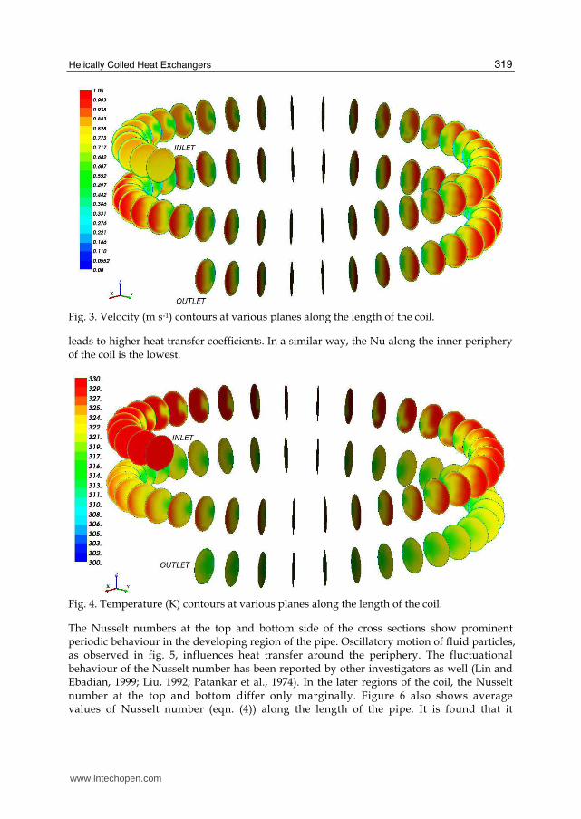
Fig. 3 shows an overview of velocity contours at various sections along the length of the coil.
The planes are identified by the angle (θ) which is the angle that the plane makes with the
plane passing through the pipe inlet. In fig. 5 the first plane shown on the top is at 10o from
the inlet (i.e., θ=10o) and the subsequent planes are 10o apart. Up to an angle of θ=35o, the
velocity profile at a cross section is found to be symmetric. Subsequently, this uniform
velocity pattern changes to a pattern with a high velocity region located at the outer side of
the coil. This behaviour is seen predominantly by θ=45o and continues to develop. It can be
seen that by θ=135o, the high velocity region is present only in outer half cross-section. Area
of high velocity region further reduces as the flow gets developed and covers approximately 1
3rd of the flow area by θ=240o. No significant change in flow pattern is observed
downstream.
Temperature distribution at various planes along the length of coil is shown in fig. 4. At the inlet, temperature is uniform across the cross section. Since the wall is maintained at a lower temperature, the fluid cools down as it flows through the coil. Up to an angle of 20o, heat transfer is uniform along the periphery. In contrast to heat transfer in a straight tube, high temperature regions are seen on the outer side of the coil. This phenomena is predominant from the plane at angle θ=50o. This trend continues to develop and by 150o, clearly three regions viz., high temperature (327-330 K) at the outer side of the coil, intermediate temperature (321 to 324 K) at the centre and low temperature (311 to 314 K) on the inner side of the coil, are visible. As the fluid flows down the pipe, this temperature profile gets developed and the area of high temperature region decreases and by θ = 360o, a fully developed temperature profile is attained and the fluid continues to lose heat due to the lower wall temperature.
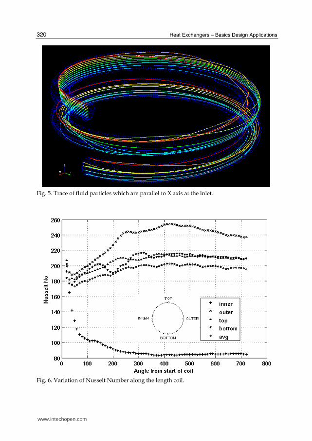
As the fluid flows through the helical coil, fluid particles undergo rotational motion. The
fluid particles also undergo movement from inner side of the coil to the outer side and vice-
versa. Fig. 5 shows particle trace for 10 fluid particles which are located along a line parallel
to the X axis at the pipe inlet. It can be noted that these fluid particles are taking various
trajectories and also move with different velocities. The particles, which were forming a line
to begin with, are found to be totally scattered at the pipe exit. It can be clearly seen that the
high velocity region oscillates as the fluid flows along the helical pipe. This causes
fluctuations in the values of Nusselt number.
Variation of local Nusselt number along the length of the tube is presented in fig. 6. The X axis of the figure is the angle of the plane, starting from the pipe inlet. It is found that the Nusselt number on the outer side of the coil is higher than those at any other location at that cross-section. Due to the centrifugal forces, the velocity in the outer region is higher and this
www.intechopen.com
Helically Coiled Heat Exchangers
319
Fig. 3. Velocity (m s-1) contours at various planes along the length of the coil.
leads to higher heat transfer coefficients. In a similar way, the Nu along the inner periphery of the coil is the lowest.
Fig. 4. Temperature (K) contours at various planes along the length of the coil.
The Nusselt numbers at the top and bottom side of the cross sections show prominent periodic behaviour in the developing region of the pipe. Oscillatory motion of fluid particles, as observed in fig. 5, influences heat transfer around the periphery. The fluctuational behaviour of the Nusselt number has been reported by other investigators as well (Lin and Ebadian, 1999; Liu, 1992; Patankar et al., 1974). In the later regions of the coil, the Nusselt number at the top and bottom differ only marginally. Figure 6 also shows average values of Nusselt number (eqn. (4)) along the length of the pipe. It is found that it
www.intechopen.com
Heat Exchangers – Basics Design Applications
320
Fig. 5. Trace of fluid particles which are parallel to X axis at the inlet.
Fig. 6. Variation of Nusselt Number along the length coil.
www.intechopen.com

Helically Coiled Heat Exchangers
321
attains an almost constant value by 300o. This constant value is used in the developing correlations for estimation of Nusselt number. Apart from the centrifugal action, buoyancy effects will move the hot particles upward and then downward as it loses heat (as can be seen in fig 5). This up and down movements together with centrifugal and inertial forces will lead to an overall spiral movement of the fluid. This may be attributed to the periodic behaviour of Nusselt number at top and bottom sides of the cross sections along the length of the pipe.
It may be noted that commercial CFD codes may not provide the value of bulk fluid temperature at different cross-section for estimation of the local Nusselt numbers. The user may be able to specify only a single value of bulk fluid temperature for the entire computational domain. This can lead to estimation of incorrect values of Nusselt numbers.
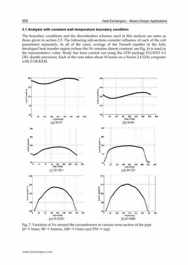
Variation of local values of Nusselt number along the periphery of the pipe wall at various locations of the pipe are shown in Fig. 7. In these figures, the angle θ refers to the angle which the current plane makes with the inlet plane. In the initial length of the pipe, up to an angle θ=10o, marginally higher rates of heat transfer is observed at the upper side of the pipe. Due to gravity effect, the hotter fluid will be present at the top and this result in higher values of Nusselt number at that location. As the flow gets developed, when the effect of centrifugal forces becomes appreciable, region of higher heat transfer shifts from angle 270o to 180o i.e. from the upper side of the pipe to outer side of the coil. This shift gets completed by θ=76o. It is observed that up to an angle of 140o, the percentage of circumference, which has a higher value of Nu is predominant. This percentage decreases and by θ=430o onwards this region is so low that the average Nusselt number starts decreasing. Bai et al. (1999) has provided a figure showing ratio of local Nusselt number to average Nusselt number (only at 8 angular locations around the periphery) for turbulent heat transfer in a horizontally oriented helical coil. They have also obtained a similar pattern in the fully developed region as the one presented here.
3. Correlations for estimation of average Nusselt number
A correlation for estimation of inside heat transfer coefficient for flow of single-phase water through helically coiled heat exchangers is presented in previous section. (Jayakumar et al., 2008a). The correlation, which is validated against experiments, is applicable to the specific configuration of helical coil, since the research work was limited only to changes in flow rate of the streams. This section deals with the analysis of various configurations of helical coils. After establishing influence of the coil parameters, correlations for prediction of average Nusselt number have been developed. Subsequently correlation to predict the local values of Nusselt number as a function of angular location is presented.
CFD simulations are carried out by varying coil parameters such as (i) pitch circle diameter, (ii) tube pitch and (iii) pipe diameter and their influence on heat transfer has been studied. Helical coils of different configurations have been analysed for this purpose. The results of these computations (where temperature dependant fluid properties are used) are used for developing unified correlations for estimation of inside heat transfer coefficient for flow of single-phase water through helical coils. Since a large data set is considered, the correlation will be applicable to a wide range of coil configurations and Dean numbers. Analysis has been carried out with both constant wall temperature and constant wall heat flux boundary conditions in order to establish influence of the boundary condition on heat transfer coefficient.
www.intechopen.com
Heat Exchangers – Basics Design Applications
322
3.1 Analysis with constant wall temperature boundary condition
The boundary conditions and the discretisation schemes used in this analysis are same as those given in section 2.3. The following sub-sections consider influence of each of the coil parameters separately. In all of the cases, average of the Nusselt number in the fully developed heat transfer region (where the Nu remains almost constant, see Fig. 6) is used as the representative value. Study has been carried out using the CFD package FLUENT 6.3 (3D, double precision). Each of the runs takes about 10 hours on a Xenon 2.4 GHz computer with 2 GB RAM.
(a) θ=2o (b) θ=8o
(c) θ=30 o (d) θ=72o
(e) θ=210o (f) θ=380o
Fig. 7. Variation of Nu around the circumference at various cross section of the pipe (0o Inner, 90o bottom, 180o Outer and 270o top).
www.intechopen.com
Helically Coiled Heat Exchangers
323
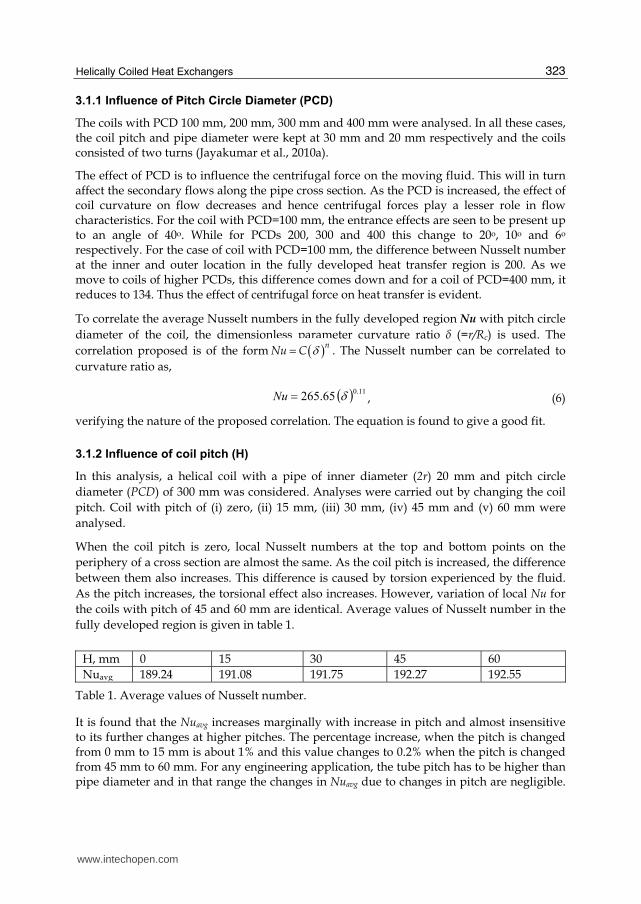
3.1.1 Influence of Pitch Circle Diameter (PCD)
The coils with PCD 100 mm, 200 mm, 300 mm and 400 mm were analysed. In all these cases, the coil pitch and pipe diameter were kept at 30 mm and 20 mm respectively and the coils consisted of two turns (Jayakumar et al., 2010a).
The effect of PCD is to influence the centrifugal force on the moving fluid. This will in turn affect the secondary flows along the pipe cross section. As the PCD is increased, the effect of coil curvature on flow decreases and hence centrifugal forces play a lesser role in flow characteristics. For the coil with PCD=100 mm, the entrance effects are seen to be present up to an angle of 40o. While for PCDs 200, 300 and 400 this change to 20o, 10o and 6o respectively. For the case of coil with PCD=100 mm, the difference between Nusselt number at the inner and outer location in the fully developed heat transfer region is 200. As we move to coils of higher PCDs, this difference comes down and for a coil of PCD=400 mm, it reduces to 134. Thus the effect of centrifugal force on heat transfer is evident.
To correlate the average Nusselt numbers in the fully developed region Nu with pitch circle
diameter of the coil, the dimensionless parameter curvature ratio ├ (=r/Rc) is used. The
correlation proposed is of the form nNu C . The Nusselt number can be correlated to
curvature ratio as,
11.0 265.65 Nu , (6)
verifying the nature of the proposed correlation. The equation is found to give a good fit.
3.1.2 Influence of coil pitch (H)
In this analysis, a helical coil with a pipe of inner diameter (2r) 20 mm and pitch circle
diameter (PCD) of 300 mm was considered. Analyses were carried out by changing the coil
pitch. Coil with pitch of (i) zero, (ii) 15 mm, (iii) 30 mm, (iv) 45 mm and (v) 60 mm were
analysed.
When the coil pitch is zero, local Nusselt numbers at the top and bottom points on the
periphery of a cross section are almost the same. As the coil pitch is increased, the difference
between them also increases. This difference is caused by torsion experienced by the fluid.
As the pitch increases, the torsional effect also increases. However, variation of local Nu for
the coils with pitch of 45 and 60 mm are identical. Average values of Nusselt number in the
fully developed region is given in table 1.
H, mm 0 15 30 45 60
Nuavg 189.24 191.08 191.75 192.27 192.55
Table 1. Average values of Nusselt number.
It is found that the Nuavg increases marginally with increase in pitch and almost insensitive to its further changes at higher pitches. The percentage increase, when the pitch is changed from 0 mm to 15 mm is about 1% and this value changes to 0.2% when the pitch is changed from 45 mm to 60 mm. For any engineering application, the tube pitch has to be higher than pipe diameter and in that range the changes in Nuavg due to changes in pitch are negligible.
www.intechopen.com
Heat Exchangers – Basics Design Applications
324
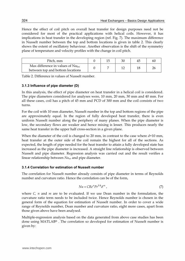
Hence the effect of coil pitch on overall heat transfer for design purposes need not be considered for most of the practical applications with helical coils. However, it has implications in heat transfer in the developing region (ref. Fig. 7). The maximum difference in Nusselt number between the top and bottom locations is given in table 2. This clearly shows the extent of oscillatory behaviour. Another observation is the shift of the symmetry plane of temperature and velocity profiles with the change in coil pitch.
Pitch, mm 0 15 30 45 60
Max difference in values of Nuloc between top and bottom locations
0 7 12 18 26
Table 2. Difference in values of Nusselt number.
3.1.3 Influence of pipe diameter (D)
In this analysis, the effect of pipe diameter on heat transfer in a helical coil is considered. The pipe diameters considered for analyses were, 10 mm, 20 mm, 30 mm and 40 mm. For all these cases, coil has a pitch of 45 mm and PCD of 300 mm and the coil consists of two turns.
For the coil with 10 mm diameter, Nusselt number in the top and bottom regions of the pipe
are approximately equal. In the region of fully developed heat transfer, there is even
uniform Nusselt number along the periphery of many planes. When the pipe diameter is
low, the secondary flows are weaker and hence mixing is lesser. This produces nearly the
same heat transfer in the upper half cross-section in a given plane.
When the diameter of the coil is changed to 20 mm, in contrast to the case where d=10 mm,
heat transfer at the outer side of the coil remain the highest for all of the sections. As
expected, the length of pipe needed for the heat transfer to attain a fully developed state has
increased as the pipe diameter is increased. A straight line relationship is observed between
Nusselt and pipe diameter. Regression analysis was carried out and the result verifies a
linear relationship between Nuav and pipe diameter.
3.1.4 Correlation for estimation of Nusselt number
The correlation for Nusselt number already consists of pipe diameter in terms of Reynolds number and curvature ratio. Hence the correlation can be of the form,
0.4n mNu CRe Pr , (7)
where C, n and m are to be evaluated. If we use Dean number in the formulation, the curvature ratio term needs to be included twice. Hence Reynolds number is chosen in the general form of the equation for estimation of Nusselt number. In order to cover a wide range of Reynolds number, Dean number and curvature ratio, eight more cases, apart from those given above have been analysed.
Multiple-regression analysis based on the data generated from above case studies has been done using MATLAB® . The correlation so developed for estimation of Nusselt number is given by:
www.intechopen.com
Helically Coiled Heat Exchangers
325
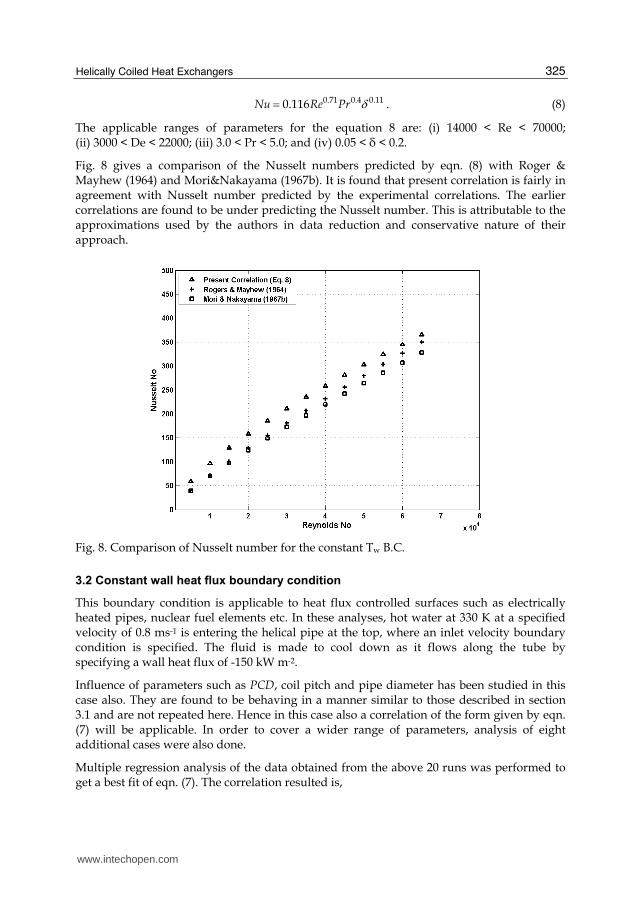
0.71 0.4 0.110.116Nu Re Pr . (8)
The applicable ranges of parameters for the equation 8 are: (i) 14000 < Re < 70000; (ii) 3000 < De < 22000; (iii) 3.0 < Pr < 5.0; and (iv) 0.05 < δ < 0.2.
Fig. 8 gives a comparison of the Nusselt numbers predicted by eqn. (8) with Roger & Mayhew (1964) and Mori&Nakayama (1967b). It is found that present correlation is fairly in agreement with Nusselt number predicted by the experimental correlations. The earlier correlations are found to be under predicting the Nusselt number. This is attributable to the approximations used by the authors in data reduction and conservative nature of their approach.
Fig. 8. Comparison of Nusselt number for the constant Tw B.C.
3.2 Constant wall heat flux boundary condition
This boundary condition is applicable to heat flux controlled surfaces such as electrically heated pipes, nuclear fuel elements etc. In these analyses, hot water at 330 K at a specified velocity of 0.8 ms-1 is entering the helical pipe at the top, where an inlet velocity boundary condition is specified. The fluid is made to cool down as it flows along the tube by specifying a wall heat flux of -150 kW m-2.
Influence of parameters such as PCD, coil pitch and pipe diameter has been studied in this case also. They are found to be behaving in a manner similar to those described in section 3.1 and are not repeated here. Hence in this case also a correlation of the form given by eqn. (7) will be applicable. In order to cover a wider range of parameters, analysis of eight additional cases were also done.
Multiple regression analysis of the data obtained from the above 20 runs was performed to get a best fit of eqn. (7). The correlation resulted is,
www.intechopen.com
Heat Exchangers – Basics Design Applications
326
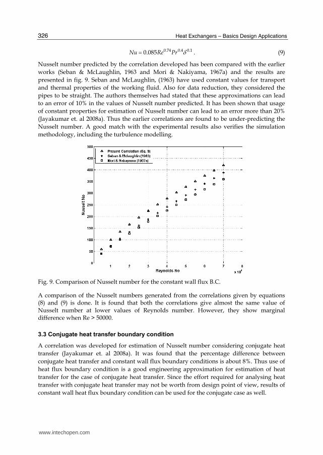
0.74 0.4 0.10.085Nu Re Pr . (9)
Nusselt number predicted by the correlation developed has been compared with the earlier
works (Seban & McLaughlin, 1963 and Mori & Nakiyama, 1967a) and the results are
presented in fig. 9. Seban and McLaughlin, (1963) have used constant values for transport
and thermal properties of the working fluid. Also for data reduction, they considered the
pipes to be straight. The authors themselves had stated that these approximations can lead
to an error of 10% in the values of Nusselt number predicted. It has been shown that usage
of constant properties for estimation of Nusselt number can lead to an error more than 20%
(Jayakumar et. al 2008a). Thus the earlier correlations are found to be under-predicting the
Nusselt number. A good match with the experimental results also verifies the simulation
methodology, including the turbulence modelling.
Fig. 9. Comparison of Nusselt number for the constant wall flux B.C.
A comparison of the Nusselt numbers generated from the correlations given by equations (8) and (9) is done. It is found that both the correlations give almost the same value of Nusselt number at lower values of Reynolds number. However, they show marginal difference when Re > 50000.
3.3 Conjugate heat transfer boundary condition
A correlation was developed for estimation of Nusselt number considering conjugate heat
transfer (Jayakumar et. al 2008a). It was found that the percentage difference between
conjugate heat transfer and constant wall flux boundary conditions is about 8%. Thus use of
heat flux boundary condition is a good engineering approximation for estimation of heat
transfer for the case of conjugate heat transfer. Since the effort required for analysing heat
transfer with conjugate heat transfer may not be worth from design point of view, results of
constant wall heat flux boundary condition can be used for the conjugate case as well.
www.intechopen.com
Helically Coiled Heat Exchangers
327
4. Estimation of local Nusselt number
It has been shown that the heat transfer and hence the Nusselt number is not uniform along the periphery at any given cross-section of the helical pipe (Jayakumar, 2009). In section 3, the development of Nusselt number along the periphery was discussed. It will be useful to find out a relationship to predict the local values of Nusselt number Nuloc.as a function of the angular location and this is presented in this section.
4.1 Constant wall temperature boundary condition
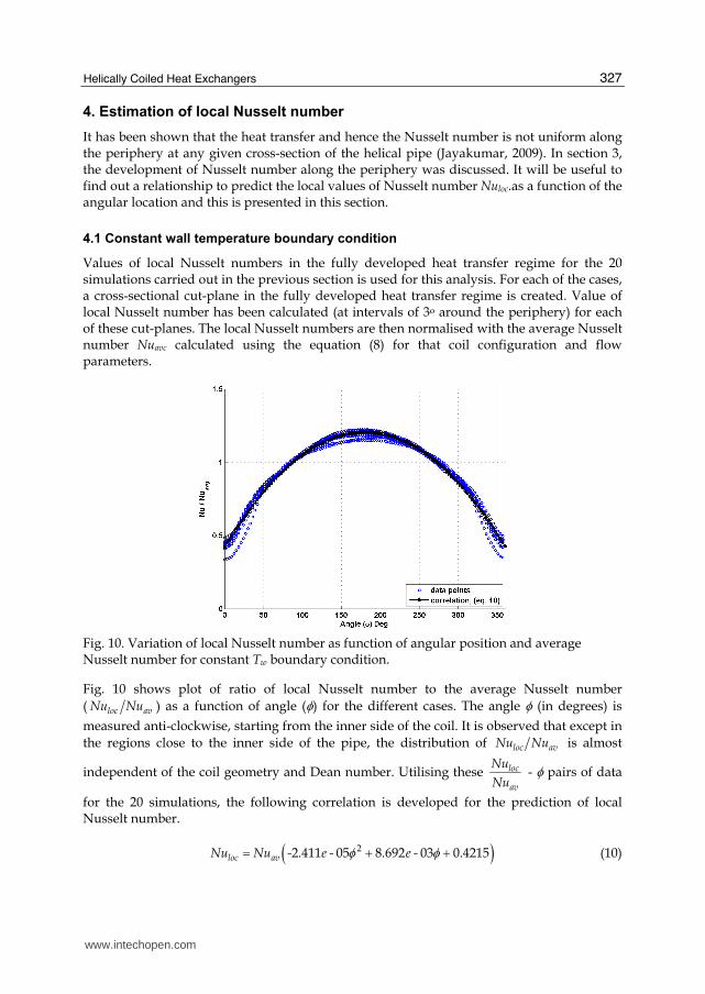
Values of local Nusselt numbers in the fully developed heat transfer regime for the 20 simulations carried out in the previous section is used for this analysis. For each of the cases, a cross-sectional cut-plane in the fully developed heat transfer regime is created. Value of local Nusselt number has been calculated (at intervals of 3o around the periphery) for each of these cut-planes. The local Nusselt numbers are then normalised with the average Nusselt number Nuavc calculated using the equation (8) for that coil configuration and flow parameters.
Fig. 10. Variation of local Nusselt number as function of angular position and average Nusselt number for constant Tw boundary condition.
Fig. 10 shows plot of ratio of local Nusselt number to the average Nusselt number
( loc avNu Nu ) as a function of angle () for the different cases. The angle (in degrees) is
measured anti-clockwise, starting from the inner side of the coil. It is observed that except in
the regions close to the inner side of the pipe, the distribution of loc avNu Nu is almost
independent of the coil geometry and Dean number. Utilising these loc
av
Nu
Nu - pairs of data
for the 20 simulations, the following correlation is developed for the prediction of local Nusselt number.
22 411 05 8 692 03 0.4215loc avNu Nu - . e - . e - (10)
www.intechopen.com
Heat Exchangers – Basics Design Applications
328
In this relation the angular location is to be expressed in degrees and the average Nusselt number Nuavc is calculated using eqn. (8). Hence the applicability of equation 10 is same as that of eqn. (8).
4.2 Constant wall heat flux boundary condition
A similar exercise has been carried out to correlate the variation of local Nusselt number for
the constant wall heat flux boundary condition. The plot of loc avNu Nu as a function of for
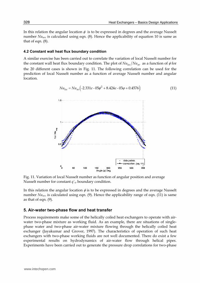
the 20 different cases is shown in Fig. 11. The following correlation can be used for the prediction of local Nusselt number as a function of average Nusselt number and angular location.
22 331 05 8 424 03 0.4576loc avNu Nu - . e - . e - (11)
Fig. 11. Variation of local Nusselt number as function of angular position and average Nusselt number for constant q”w boundary condition.
In this relation the angular location is to be expressed in degrees and the average Nusselt number Nuavc is calculated using eqn. (9). Hence the applicability range of eqn. (11) is same as that of eqn. (9).
5. Air-water two-phase flow and heat transfer
Process requirements make some of the helically coiled heat exchangers to operate with air-water two-phase mixture as working fluid. As an example, there are situations of single-phase water and two-phase air-water mixture flowing through the helically coiled heat exchanger (Jayakumar and Grover, 1997). The characteristics of operation of such heat exchangers with two-phase working fluids are not well documented. There do exist a few experimental results on hydrodynamics of air-water flow through helical pipes. Experiments have been carried out to generate the pressure drop correlations for two-phase
www.intechopen.com
Helically Coiled Heat Exchangers
329
flow of air-water through helical pipes. However numerical investigation, which can give much insight into the physics of the problem, is lacking. No work is reported on detailed numerical study of hydrodynamics and heat transfer characteristics for air-water two-phase flow through such systems. A numerical study can give much more insight into the phenomena and further, the influence of various parameters can also be studied. Jayakumar et al. (2008b, 2010b) have carried out heat transfer studies of flow of two-phase air-water mixture through helical coils. This paper gives a clear picture on the influence of velocity, temperature and void fraction on the coil parameters. The work also gives details of benchmarking for hydrodynamic and heat transfer analysis of air-water mixture through helical coils.
The modified Lockhart-Martinelli parameter (χ) is defined as,
HgHl dz
dP
dz
dP
,,
2
(12)
where, the subscript H refers to pressure drop in helical coils.
The Lockhart-Martinelli parameter (χ) was estimated and two-phase pressure drop is calculated using the functional relationships of two-phase friction multipliers, фl and фg.
Xfdz
dP
dz
dP
HlHTP
l 1
,,
2
(13)
Xfdz
dP
dz
dP
HgHTP
g 2
,,
2
(14)
5.1 Schemes for two-phase flow modelling
For modelling two-phase flows, one can use either Eulerian-Lagrangian model or Eulerian-
Eulerian approach. The first one is generally used to trace the particles and hence is not
appropriate to deal with gas-liquid flows in pipes. In the Eulerian-Eulerian approach, the
phases are treated as interpenetrating and void fraction is used to distinguish the phases.
There are 3 different schemes possible in this method, viz., Volume Of Fluid (VOF) model,
the mixture model and the Eulerian model. The VOF is applicable when surface tracking is
of importance and in the mixture model, pseudo properties of the mixture are used to solve
a single set of conservation equations. However, in the Eulerian model, complete set of
conservation equations are solved for each of the phases. Thus, either the mixture model or
the Eulerian model may be applied for solution of two-phase flow through the helical coil
system. Due to the centrifugal and corioli’s forces generated during the flow in a helical
pipe, a well-mixed gas-liquid region will not be probable and use of mixture properties for
the flow will not yield a correct solution. Hence, it is decided to use the Euler scheme to be
used for the modelling.
5.2 Governing equations for modelling Eulerian two-phase scheme
Heat transfer to flow of air-water mixture through a helical pipe, where the pipe wall has been kept at a constant temperature, is analysed with Eulerian model of two-phase flows
www.intechopen.com
Heat Exchangers – Basics Design Applications
330
using the CFD package FLUENT. Conservation equations are solved for each of the phase k, viz., gas (g) and liquid (l). In describing the two-phase flow, which has been treated as interpenetrating continua, the concept of void fraction is used. The void fraction of any phase represents the fraction of volume (of the total volume) occupied by that phase. The volume of a phase k is defined as,
V
kk dVV (15)
where, the summation of the void fractions is unity.
1 lg (16)
5.2.1 Conservation of mass
The continuity equation for the phase k is expressed as,
. .
,
pq qpk k k k kp l g
m m St
ku (17)
Here . .
pq qpm m is the mass exchange between the liquid and gaseous phases. In the present
case, since no mass exchange takes place between the phases, the source Sk is zero.
5.2.2 Conservation of momentum
The set of equations for conservation of momentum for the phase k is written as,
kkk
pq
kkk
FFF
uuR
gτuuu
,,
,
.
vmlift
glp
qpqppqpq
kkkkkkkk
mm
pt
(18)
Here upq is the interphase velocity and Rpq is the interaction between the phases. Fk is external body force, Fvm k virtual mass force and Flift, k is the lift force. The stress – strain
tensor is defined as:
Iuuu k
T
kkτ
kkkkk 3
2 (19)
In this relation, k and k are the shear and bulk viscosity of the phase k. The inter-phase
force, Rpq is evaluated from , ,
qp l g p l g
pq pq pR K u u , where Kpq is the inter-phase
momentum exchange coefficient. The coefficient Kpq can be estimated using the relation,
www.intechopen.com
Helically Coiled Heat Exchangers
331
p
ppq
pq
fK
, (20)
where f is the drag function and p is the particulate relaxation time. In the present analysis,
24
RedCf , (21)
where Cd is evaluated from the expression,
1000 for Re 44.0
1000 for Re Re/Re15.0124687.0
dC (22)
and Re is the relative Reynolds number, which is evaluated using the expression,
q
pq d
qp uu Re , (23)
for the primary phase. The particulate relaxation time is defined as
q
pp
p
d
18
2 , (24)
Lift force on the secondary phase (droplets or bubbles) is due to the velocity gradient in the primary-phase flow field. The lift force acting on a secondary phase p in a primary phase q is computed using the relation,
qpq uuuF pqlift 5.0 (25)
Virtual mass force, which occurs when the secondary phase (p) accelerates relative to the primary phase (q), is estimated using,
Dt
D
Dt
Dpqvm
pq uuF 5.0 , (26)
where DtD
is the material derivative of . Virtual mass effect is significant when the density
of the secondary phase is much smaller than that of primary phase.
5.2.3 Conservation of energy
The energy balance equation for the phase k is expressed as,
glp
qpqppqpqpq
kkk
kkkkkkk
hmhmQ
St
phh
t
,
.
: kkk quτu (27)
www.intechopen.com
Heat Exchangers – Basics Design Applications
332
In this equation, hk is the specific enthalpy, qk is heat flux and Sk is the heat generation for the phase. Qpq is the heat exchange between the phases and hpq is interphase enthalpy.
5.2.4 Turbulence modelling
Turbulence is modelled using multiphase “mixture k-┝ model” based on the realizable k-┝ model. It has already stated that realizable model is the most appropriate one for flows with rotation, adverse pressure gradient etc. Usage of other models, viz., dispersed model and per phase model are computationally very expensive. The transport equations for the mixture k and ┝ are as follows.
mmk
k
mt
mm Gkkkt
,
,
mu (28)
and
mmk
mt
mm CGCkt
2,1
,
mu (29)
where, the subscript m stands for the mixture. Production of turbulent energy is calculated from,
mmm uuu :,,
T
mtmkG (30)
The mixture density and velocity are evaluated using ,
m i ik l g
and ,
,
i ik l g
i ik l g
i
m
u
u
respectively. The turbulent viscosity is estimated using 2
,t m m
kC . The model
constants are same as those used for the single-phase realizable k-┝ model.
5.3 Estimation of two-phase heat transfer coefficient
Hydrodynamics of air-water two-phase flow through helical pipes are validated against the
experimental results generated by previous researchers. Heat transfer calculations for the
two-phase flow are validated against experimental results of flow through an annular pipe
(Jayakumar et al., 2010b). In the section 3 details of heat transfer characteristics along the
length of the pipe for single-phase fluid have been presented. These give us qualitative
picture of various phenomena at various flow sections of the pipe. Quantitative studies of
heat transfer with an objective to derive a heat transfer correlation are taken-up in the
present chapter. For this 11 coil configurations were analysed.
The analyses have been carried out with a constant wall heat flux boundary condition. The
wall heat flux imposed was -150 kW m-2. In all cases, uniform inlet velocity of 0.8 m s-1 was
specified for the phases. The air void fraction at the inlet was taken to be 0.2. The numerical
schemes used in these analyses are same as those described in the previous chapter.
www.intechopen.com
Helically Coiled Heat Exchangers
333
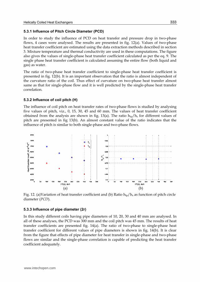
5.3.1 Influence of Pitch Circle Diameter (PCD)
In order to study the influence of PCD on heat transfer and pressure drop in two-phase flows, 4 cases were analysed. The results are presented in fig. 12(a). Values of two-phase heat transfer coefficient are estimated using the data extraction methods described in section 3. Mixture temperature and thermal conductivity are used in these computations. The figure also gives the values of single-phase heat transfer coefficient calculated as per the eq. 9. The single phase heat transfer coefficient is calculated assuming the entire flow (both liquid and gas) as water.
The ratio of two-phase heat transfer coefficient to single-phase heat transfer coefficient is presented in fig. 12(b). It is an important observation that the ratio is almost independent of the curvature ratio of the coil. Thus effect of curvature on two-phase heat transfer almost same as that for single-phase flow and it is well predicted by the single-phase heat transfer correlation.
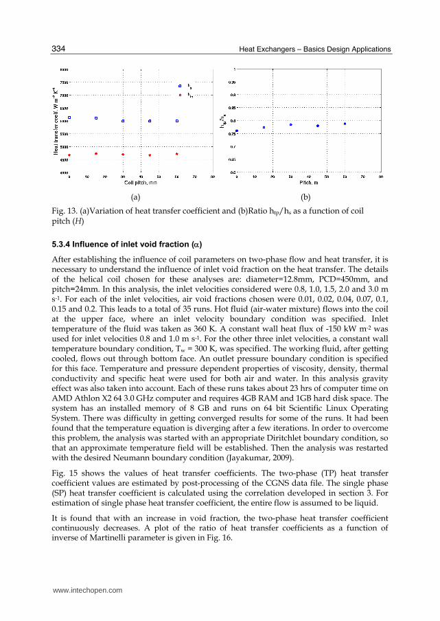
5.3.2 Influence of coil pitch (H)
The influence of coil pitch on heat transfer rates of two-phase flows is studied by analysing five values of pitch, viz., 0, 15, 30, 45 and 60 mm. The values of heat transfer coefficient obtained from the analysis are shown in fig. 13(a). The ratio htp/hs for different values of pitch are presented in fig 13(b). An almost constant value of the ratio indicates that the influence of pitch is similar to both single-phase and two-phase flows.
(a) (b)
Fig. 12. (a)Variation of heat transfer coefficient and (b) Ratio htp/hs as function of pitch circle diameter (PCD).
5.3.3 Influence of pipe diameter (2r)
In this study different coils having pipe diameters of 10, 20, 30 and 40 mm are analysed. In all of these analyses, the PCD was 300 mm and the coil pitch was 45 mm. The results of heat transfer coefficients are presented fig. 14(a). The ratio of two-phase to single-phase heat transfer coefficient for different values of pipe diameters is shown in fig. 14(b). It is clear from the figure that effects of pipe diameter for heat transfer in single-phase and two-phase flows are similar and the single-phase correlation is capable of predicting the heat transfer coefficient adequately.
www.intechopen.com
Heat Exchangers – Basics Design Applications
334
(a) (b)
Fig. 13. (a)Variation of heat transfer coefficient and (b)Ratio htp/hs as a function of coil pitch (H)
5.3.4 Influence of inlet void fraction ()
After establishing the influence of coil parameters on two-phase flow and heat transfer, it is necessary to understand the influence of inlet void fraction on the heat transfer. The details of the helical coil chosen for these analyses are: diameter=12.8mm, PCD=450mm, and pitch=24mm. In this analysis, the inlet velocities considered were 0.8, 1.0, 1.5, 2.0 and 3.0 m s-1. For each of the inlet velocities, air void fractions chosen were 0.01, 0.02, 0.04, 0.07, 0.1, 0.15 and 0.2. This leads to a total of 35 runs. Hot fluid (air-water mixture) flows into the coil at the upper face, where an inlet velocity boundary condition was specified. Inlet temperature of the fluid was taken as 360 K. A constant wall heat flux of -150 kW m-2 was used for inlet velocities 0.8 and 1.0 m s-1. For the other three inlet velocities, a constant wall temperature boundary condition, Tw = 300 K, was specified. The working fluid, after getting cooled, flows out through bottom face. An outlet pressure boundary condition is specified for this face. Temperature and pressure dependent properties of viscosity, density, thermal conductivity and specific heat were used for both air and water. In this analysis gravity effect was also taken into account. Each of these runs takes about 23 hrs of computer time on AMD Athlon X2 64 3.0 GHz computer and requires 4GB RAM and 1GB hard disk space. The system has an installed memory of 8 GB and runs on 64 bit Scientific Linux Operating System. There was difficulty in getting converged results for some of the runs. It had been found that the temperature equation is diverging after a few iterations. In order to overcome this problem, the analysis was started with an appropriate Diritchlet boundary condition, so that an approximate temperature field will be established. Then the analysis was restarted with the desired Neumann boundary condition (Jayakumar, 2009).
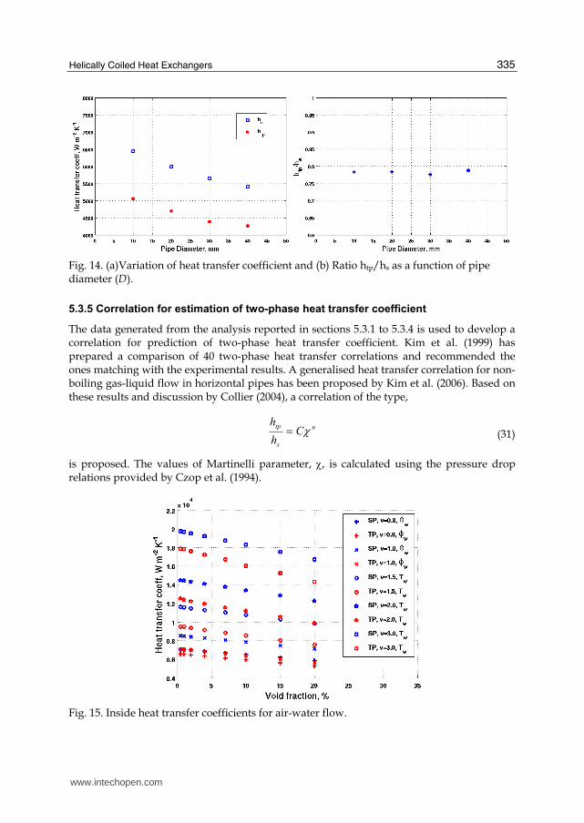
Fig. 15 shows the values of heat transfer coefficients. The two-phase (TP) heat transfer coefficient values are estimated by post-processing of the CGNS data file. The single phase (SP) heat transfer coefficient is calculated using the correlation developed in section 3. For estimation of single phase heat transfer coefficient, the entire flow is assumed to be liquid.
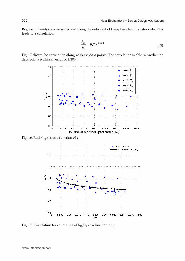
It is found that with an increase in void fraction, the two-phase heat transfer coefficient continuously decreases. A plot of the ratio of heat transfer coefficients as a function of inverse of Martinelli parameter is given in Fig. 16.
www.intechopen.com
Helically Coiled Heat Exchangers
335
Fig. 14. (a)Variation of heat transfer coefficient and (b) Ratio htp/hs as a function of pipe diameter (D).
5.3.5 Correlation for estimation of two-phase heat transfer coefficient
The data generated from the analysis reported in sections 5.3.1 to 5.3.4 is used to develop a correlation for prediction of two-phase heat transfer coefficient. Kim et al. (1999) has prepared a comparison of 40 two-phase heat transfer correlations and recommended the ones matching with the experimental results. A generalised heat transfer correlation for non-boiling gas-liquid flow in horizontal pipes has been proposed by Kim et al. (2006). Based on these results and discussion by Collier (2004), a correlation of the type,
n
s
tpC
h
h (31)
is proposed. The values of Martinelli parameter, , is calculated using the pressure drop relations provided by Czop et al. (1994).
Fig. 15. Inside heat transfer coefficients for air-water flow.
www.intechopen.com
Heat Exchangers – Basics Design Applications
336
Regression analysis was carried out using the entire set of two-phase heat transfer data. This leads to a correlation,
0424.0
7.0 s
tp
h
h (32)
Fig. 17 shows the correlation along with the data points. The correlation is able to predict the
data points within an error of 10%.
Fig. 16. Ratio htp/hs as a function of
Fig. 17. Correlation for estimation of htp/hs as a function of
www.intechopen.com
Helically Coiled Heat Exchangers
337
6. Conclusion
It is observed that the use of constant values for the thermal and transport properties of the heat transport medium results in prediction of inaccurate heat transfer coefficients. Heat transfer characteristics of the heat exchanger with helical coil are also studied using the CFD code. The CFD predictions match reasonably well with the experimental results within experimental error limits. Based on the results a correlation was developed to calculate the inside heat transfer coefficient of the helical coil.
Necessary Python codes, which run in the framework of AnuVi visualisation package, have been developed for accurate estimation of Nusselt number at any point on the heat transfer surface. The research work also includes development of various C++ and MATLAB® codes.
Characteristics of non-isothermal fluid flow and heat transfer under turbulent flow of single phase water through helical coils have been presented in detail. Analysis has been carried out both for the constant wall temperature and constant wall heat flux boundary conditions. Fluid particles are found to undergo oscillatory motion inside the pipe and this causes fluctuations in heat transfer rates.
Nusselt numbers at various points along the length of the pipe was estimated. Nusselt number on the outer side of the coil is found to be the highest among all other points at a specified cross-section, while that at the inner side of the coil is the lowest. Velocity profiles for the two boundary conditions were found to be matching, while the temperature profiles are different.
A number of numerical experiments have been carried out to study influence of coil
parameters, viz., pitch circle diameter, coil pitch and pipe diameter on heat transfer. The coil
pitch is found to have significance only in the developing section of heat transfer. The
torsional forces induced by the pitch causes oscillations in the Nusselt number. However,
the average Nusselt number is not affected by the coil pitch. After establishing the
parametric influence, a correlation has been developed for estimation of average Nusselt
number. This correlation is compared with those available in the literature and the
deviations are within reasonable limits. It is also observed that these correlations are
applicable for either of the boundary conditions. For most of the engineering applications,
the correlations are applicable for conjugate heat transfer as well.
In the fully developed section, ratio Nuloc/Nuav is almost independent of coil parameters
and Dean number. Correlations have been developed for prediction of local values of
Nusselt number as a function of the average Nusselt number and the angular position of the
point along the circumference.
CFD simulations of heat transfer to air-water two-phase mixture flowing through a helically
coiled heat exchanger has been carried out. Studies have been carried out by varying (i) coil
pitch, (ii) pipe diameter (iii) pitch circle diameter. Their influence on heat transfer and
pressure drop has been brought out.
Unlike the flow through a straight pipe, the centrifugal force caused due to the curvature of the pipe causes heavier fluid (water-phase) to flow along the outer side of the pipe. High velocity and high temperature are also observed along the outer side. The torsion caused by pitch of the coil makes the flow unsymmetrical about the horizontal plane of coil. As the
www.intechopen.com
Heat Exchangers – Basics Design Applications
338
pitch is increased, higher velocity and higher temperature regions are observed on the bottom half of the pipe.
Increase in pipe diameter, keeping the inlet velocity constant, causes higher heat transfer coefficient and lower pressure drop. This effect is due to the influence of secondary flows. As the PCD is increased, the centrifugal forces decreases and this causes reduction of heat transfer coefficient and pressure drop.
Estimation of inner heat transfer coefficient for the two-phase flow was carried out by changing the void fraction and flow velocity. Results indicate reduction in heat transfer coefficient with increase in void fraction.
The coil parameters, viz., PCD and pipe diameter and void fraction at inlet have significant effect on the heat transfer and pressure drop for two-phase flows through helical coils. However, the effect of pitch is negligible. It has been shown that the quantitative dependence of coil parameters on heat transfer is same for both single and two phase flows. Using the data generated from about 45 numerical experiments, a correlation to estimate two-phase heat transfer coefficient is developed.
7. Nomenclature
Symbol Description and units A area, m2
Cp Specific heat, J kg-1 K-1
Dc Pitch Circle Diameter, m De
Dean number c
rRe
R
dimensionless F Force term, N h Heat transfer coefficient, W m-2K-1
H Tube pitch, m k Thermal conductivity, W m-1K-1
L Length, m n unit vector along outward normal Nu Nusselt number, dimensionless p Pressure, Pa Pr Prandtl number, dimensionless Q Heat transferred, W q heat flux, W m-2
r Inner radius of the tube, m R Resistance to the flow of thermal energy, W-1 m2 K Rc Pitch circle radius of the pipe, m Re Reynolds number, dimensionless S Source term in governing equations T Temperature, K U Overall heat transfer coefficient, W m-2K-1
u Velocity, m s-1
u Velocity vector, m s-1
V volume, m3
Greek
Void fraction, dimensionless
www.intechopen.com

Helically Coiled Heat Exchangers
339
Lockhart-Martinelli parameter, dimensionless
(temperature) difference, K δ Curvature ratio, dimensionless
Angular location along the periphery of pipe cross-section φ Two-phase friction multiplier, dimensionless
Non-dimensional pitch
viscosity, kg m-1 s-1
Angle a cut plane makes with a plane passing through pipe inlet
Density, kg m-3
τ Stress tensor, Pa Subscripts av Average b bulk fi Internal fouling fo External fouling H helical i internal k Phase, can be liquid (l) or gas (g) lift lift LM Log Mean loc local m mixture o external ov Overall pq from phase p to phase q s single-phase TP two-phase vm Virtual mass w wall
8. Acknowledgement
I express my sincere gratitude to Prof. Kannan N Iyer, Prof. S. M. Mahajani, Prof. J.C. Mandal and Prof. Vijayan P. K. for their meticulous guidance and extensive support during this research work.
9. References
Abdulla M. A., 1994, A four-region, moving-boundary model of a once through, helical coil team generator, Annals of Nuclear Energy, 21(9), 541-562
Akagawa, K., T. Sakaguchi, and M. Ueda. 1971, Study on a gas-liquid two-phase flow in helically coiled tubes. Bulletin of the JSME, Vol. 14 No. 72, pp 564-571.
Akiyama, M., Cheng, K. C., 1792, Boundary vorticity method for laminar forced convection heat transfer in curved pipes, Int. J. Heat Mass Transfer, 15:1426-1431.
Al-Hajeri M.H., A.M. Koluib, M. Mosaad, S. Al-Kulaib, 2007, Heat transfer performance during condensation of R-134a inside helicoidal tubes, Energy Conversion and Management, 48, 2309–2315
Awwad, A., R. C. Xin, Z. F. Dong, M. A. Ebadian, and H. M. Soliman., 1995, Measurement and correlation of the pressure drop in air-water two-phase flow in horizontal helicoidal pipes. Int. J Multiphase Flow, Vol. 21, No. 4, pp 607-619.
www.intechopen.com
Heat Exchangers – Basics Design Applications
340
Bai, B., L. Guo, Z. Feng, and X. Chen. 1999, Turbulent heat transfer in a horizontally coiled tube. Heat Transfer-Asian Research, 28(5), 395-403.
Berger S A, Talbot L and Yao L S, 1983, Flow in Curved Pipes, Ann. Rev. Fluid Mech., 15, 461 – 512
Chen, X. and L. Guo., 1999, Flow patterns and pressure drop in oil-air-water three-phase flow through helically coiled tubes. Int. J Multiphase Flow,, Vol. 25, pp 1053-1072.
Chisholm, D., 1967, Pressure gradient during the flow of incompressible two-phase mixtures through pipes, Venturies and Orifices, Br. Chem. Eng. 12(9), 1368-1371.
Collier J.G., Thome J.R., 1994, Convective Boiling and Condensation, third ed. Claredon Press, Oxford, England.
Colorado D., D. Papini, J.A. Hernández, L. Santini, M.E. Ricotti, 2011, International Journal of Thermal Sciences 50, 569-580.
Czop, V., D. Barbier, and S. Dong., 1994, Pressure drop, void fraction and shear stress measurements in an adiabatic two-phase flow in a coiled tube. Nucl Eng Des, Vol. 149, pp 323-333.
Futagami, K., Aoyama, Y., 1988, Laminar heat transfer in helically coiled tubes, Int. J. Heat Mass Transfer, 31, 387-396
Goering, D. J., Humphrey, J. C. A. and Greif, R., 1997, The dual influence of curvature and buoyancy in fully developed tube flows, Int. J Heat Mass Transfer, Vol 40, 2187 – 2199.
Guo,L., Chen, X., Feng, Z. and Bai, B., 1998, Transient convective heat transfer in a helical coiled tube with pulsatile fully developed turbulent flow, Int. J. Heat Mass Transfer, 31, 2867-2875.
Huttl, T.J. and Friedrich, R., 2000, Influence of curvature and torsion on turbulent flow in helically coiled pipes, Int. J. Heat Fluid Flow, 21, 345-353.
Huttl, T.J. and Friedrich, R., 2001, Direct numerical simulation of turbulent flows in curved and helically coiled pipes, Comp. Fluids, 30, 591-605.
Ito, H. 1959. Friction factors for turbulent flow in curved pipes. Journal of Basic Engineering, Transactions of the ASME, Vol. 81, 123-134.
Janssen, L. A. M., Hoogendoorn, C. J., 1978, Laminar convective heat transfer in helical coiled tubes, Int. J. Heat Mass Transfer, 21, 1197-1206.
Jayakumar J.S. and Grover, R.B., 1997, Two phase natural circulation residual heat removal, Proc. 3rd ISHMT-ASME Heat and Mass Transfer Conference, Kanpur.
Jayakumar J. S., 1999, Analysis of two-phase natural circulation system under oscillatory condtions, M Sc.(Engg.) thesis, Indian Institute of Science, Bangalore, India.
Jayakumar J. S., Grover, R. B. and Arakeri, V. H., 2002, Response of a two-phase system subject to oscillations induced by the motion of its support structure, Int. Comm. Heat Mass Transfer, 29, 519-530
Jayakumar J. S., S.M. Mahajani, J.C. Mandal, P.K. Vijayan, Rohidas Bhoi, 2008a, Experimental and CFD estimation of heat transfer in helically coiled heat exchangers Chemical Engineering Research and Design, Volume 86, Issue 3, March 2008, Pages 221-232.
Jayakumar J. S., Mahajani, S. M., Mandal, J. C. and Vijayan, P. K, 2008b, “Numerical Analysis of Heat Transfer to Air-Water Two-phase Flows in Helical Pipes”, Proceedings of ICHMT International Symposium on Advances in Computational Heat Transfer CHT-08, May 11-16, Marrakech, Morocco, CHT-08-299.
www.intechopen.com
Helically Coiled Heat Exchangers
341
Jayakumar, J. S., 2009, CFD Analysis of single-phase and two-phase flow inside helically coiled tubes, Ph.D. Thesis, Indian Institute of Technology Bombay, Mumbai, India.
Jayakumar J. S., S.M. Mahajani, J.C. Mandal, Kannan N. Iyer and P.K. Vijayan, 2010a, CFD analysis of single-phase flows inside helically coiled tubes, Computers & Chemical Engineering, Volume 34, Issue 4, April 2010, pp 430-446.
Jayakumar J. S., S.M. Mahajani, J.C. Mandal, Kannan N. Iyer, P.K. Vijayan, 2010b, Thermal hydraulic characteristics of air–water two-phase flows in helical pipes, Chemical Engineering Research and Design, Volume 88, Issue 4, April 2010, pp 501-512.
Jensen M. K. and Bergles A. E., 1981, Trans. ASME 103, 660-666 Ju H, Huang Z, Xu Y, Duan B, Yu Y. Hydraulic performance of small bending radius helical
coil-pipe. J Nucl Sci Technol 2001;18:826–31. Kang H.J., Lin C.X., Ebadian M.A., 2000, Condensation of R134a Flowing inside helicoidal
pipe, International Journal of Heat and Mass Transfer 43, 2553 – 2564 Kasturi, G. and J. B. Stepanek. 1972, Two phase flow – I. Pressure drop and void fraction
measurements in cocurrent gas-liquid flow in a coil. Chem Eng Sci, Vol. 27 pp 1871-1880.
Kim, S. E., Choudhury, D. and Patel, B., 1997, Computations of Complex Turbulent Flows Using the Commercial Code FLUENT, Proceedings of the ICASE/LaRC/AFOSR Symposium on Modeling Complex Turbulent Flows, Hampton, Virginia,.
Lin, C. X., Ebadian, M. A., 1997, Developing turbulent convective heat transfer in helical pipes, Int. J. Heat Mass Transfer, 40(16), 3861-3873
Lin, C. X., Ebadian, M. A., 1999, The effects of inlet turbulence on the development of fluid flow and heat transfer in a helically coiled pipe, Int. J. Heat Mass Transfer, 42, 739-751
Liu, S, 1992, Laminar flow and heat transfer in helical pipes with finite pitch, Ph D thesis, University of Alberta, Canada.
Lockhart, R.W. and Martinelli, R.C., 1956, “Proposed correlation of data for isothermal two-phase two-component flow in pipes”, Chem. Eng. Prog., 45, pp. 39.
Manna, R., Jayakumar, J.S. and Grover, R.B., 1996, Thermal Hydraulic design of a condenser for a natural circulation system, J. Energy, Heat and Mass Transfer, 18, 39-46
Mori, Y and Nakayama, W, 1967a, Study of forced convective heat transfer in curved pipes (2nd report), Int. J. Heat Mass Transfer, 10, 37-59.
Mori, Y and Nakayama, W, 1967b, Study of forced convective heat transfer in curved pipes (3rd report), Int. J. Heat Mass Transfer, 10, 681-695.
Murai, Y., Yoshikawa, S., Toda, S., Ishikawa, M., Yamamoto, F., 2006, Structure of air–water two-phase flow in helically coiled tubes, Nuc Eng Des., Vol. 236, pp 94–106.
Naphon P and Wongwises S., 2006, A review of flow and heat transfer characteristics in curved tubes, Renewable and sustainable energy reviews, 10, 463-490
Patankar S., Pratap V. S. and Spalding D. B., 1974, J. Fluid Mech. 62, 539-551. Prabhanjan, D. G., T. J. Rennie, and G. S. V. Raghavan. 2004. Natural convection heat
transfer from helical coiled tubes. International Journal of Thermal Sciences,.43(4), 359-365.
Rangacharyulu, K. and G. S. Davies. 1984. Pressure drop and holdup studies of air-liquid flow in helical coils. The Chem Eng J, Vol. 29, pp 41-46.
Rennie T J, Raghavan V G S, 2005, Experimental studies of a double-pipe helical heat exchanger, Experimental Thermal and Fluid Science 29, 919–924
www.intechopen.com
Heat Exchangers – Basics Design Applications
342
Rennie T.J., Raghavan, V. G. S., 2006b, “Effect of fluid thermal properties on heat transfer characteristics in a double pipe helical heat exchanger”, Int. J. Thermal Sciences, 45, 1158-1165
Rennie, T.J., Raghavan, V. G S, 2006a, Numerical studies of a double-pipe helical heat exchanger, Applied Thermal Engineering, 26, 1266-1273.
Rennie, T.J., Raghavan, V.G.S., 2007, Thermally dependent viscosity and non-Newtonian flow in a double-pipe helical heat exchanger, Applied Thermal Engineering 27 (5-6), 862-868
Rogers, G. F. C. and Mayhew, Y. R., 1964, Heat transfer and pressure loss in helically coiled tube with turbulent flow, Int J Heat Mass Transfer, 7, 1207-1216.
Ruffel, A.E., 1974, The application of heat transfer and pressure drop data to the design of helical coil once-through boilers, Multiphase Flow Systems Meet., Glasgow
Schmidt E. F., 1967, Wfirmeiibergang und Druckverlust in Rohrschlangen, G’zemieJng.-Tech., 39, 781-789.
Seban, R. A., and McLaughlin, E. F., 1963, Heat transfer in tube coils with laminar and turbulent flow, Int. J Heat Mass Transfer, 6, 387-495.
Shah, R. K. and Joshi, S. D. 1987, Convective heat transfer in curved ducts. Handbook of Single-Phase Convective Heat Transfer, S. Kakac, R. K. Shah, and W. Hung (eds.), Wiley Interscience, New York, Chapter 3.
Sreenivasan K. R. and P. J. Strykowski, “Stabilization Effects in Flow Through Helically Coiled Pipes”, Experiments in Fluids 1, 31-36 (1983)
Srinivasan P.S., Nandapurkar, S.S. and Holland, F.A., 1968, Pressure drop and heat transfer in coils, Chem. Eng. 218, CE113-CE119
Srinivasan, P. S., Nandapurkar, S. S. and Holland, F. A., 1970, Friction factor for coils, Trans. Inst. Chem. Eng., 48, T156 - T161.
Stepanek, J. B. and G. Kasturi. 1972. Two phase flow – II. Parameters for void fraction and pressure drop correlations. Chem. Eng Sci, Vol. 27, pp 1881-1891.
Tarbell J M, Samuels M R. Momentum and heat transfer in helical coils. Chem Eng J 1973;5:117–27.
Vimal Kumar, Supreet Saini, Manish Sharma and K D P Nigam, 2006, Pressure drop and heat transfer in tube-in-tube helical heat exchanger, Chem. Eng. Sci. 61, 4403 – 4416
Watanabe, O., K. Nakajima and H. Fujita. 1993, Characteristics of liquid-film thickness of air-water annular two-phase flow in helically coiled tubes. Heat Transfer – Japanese Research, Vol. 22, No. 5, pp 447-461.
Whalley, P. B. 1980, Air-water two-phase flow in a helically coiled tube. Int J Multiphase Flow, Vol. 6, No. 345-356.
Xin RC, Awwad A, Dong ZF, Ebadian MA. 1997, An experimental study of single-phase and two-phase flow pressure drop in annular helicoidal pipes. Int J Heat Fluid Flow, 18, 482–488.
Xin, R. C., A. Awwad, Z. F. Dong and M. A. Ebadian., 1996, An investigation and comparative study of the pressure drop in air-water two-phase flow in vertical helicoidal pipes. Int J Heat and Mass Transfer, Vol. 39( 4), pp 735-743.
Yang, G. and Ebadian, M. A., 1996, Turbulent forced convection in a helicoidal pipe with substantial pitch, Int. J Heat Mass Transfer, Vol 39(10), 2015 – 2032.
Yildiz, C., Bicer, Y., Pehlivan, D., 1997, Heat transfer and pressure drop in a heat exchanger with a helical pipe containing inside springs, Energy Convers. Mgmt., 38 (6), 619-624.
www.intechopen.com

Heat Exchangers - Basics Design ApplicationsEdited by Dr. Jovan Mitrovic
ISBN 978-953-51-0278-6Hard cover, 586 pagesPublisher InTechPublished online 09, March, 2012Published in print edition March, 2012
InTech EuropeUniversity Campus STeP Ri Slavka Krautzeka 83/A 51000 Rijeka, Croatia Phone: +385 (51) 770 447 Fax: +385 (51) 686 166www.intechopen.com
InTech ChinaUnit 405, Office Block, Hotel Equatorial Shanghai No.65, Yan An Road (West), Shanghai, 200040, China
Phone: +86-21-62489820 Fax: +86-21-62489821
Selecting and bringing together matter provided by specialists, this project offers comprehensive informationon particular cases of heat exchangers. The selection was guided by actual and future demands of appliedresearch and industry, mainly focusing on the efficient use and conversion energy in changing environment.Beside the questions of thermodynamic basics, the book addresses several important issues, such asconceptions, design, operations, fouling and cleaning of heat exchangers. It includes also storage of thermalenergy and geothermal energy use, directly or by application of heat pumps. The contributions arethematically grouped in sections and the content of each section is introduced by summarising the mainobjectives of the encompassed chapters. The book is not necessarily intended to be an elementary source ofthe knowledge in the area it covers, but rather a mentor while pursuing detailed solutions of specific technicalproblems which face engineers and technicians engaged in research and development in the fields of heattransfer and heat exchangers.
How to referenceIn order to correctly reference this scholarly work, feel free to copy and paste the following:
J. S. Jayakumar (2012). Helically Coiled Heat Exchangers, Heat Exchangers - Basics Design Applications, Dr.Jovan Mitrovic (Ed.), ISBN: 978-953-51-0278-6, InTech, Available from:http://www.intechopen.com/books/heat-exchangers-basics-design-applications/helically-coiled-heat-exchangers

© 2012 The Author(s). Licensee IntechOpen. This is an open access articledistributed under the terms of the Creative Commons Attribution 3.0License, which permits unrestricted use, distribution, and reproduction inany medium, provided the original work is properly cited.