helicoil catalogue
DESCRIPTION
HeliCoil CatalogueTRANSCRIPT

Insert Systems

3C E R T I F I E DISO 9001 • OS 9000
ISO 14001
Emhart Teknologies Heli-Coil Bulletin 2003 • Tel. (203) 924-4737 • Fax (800) 732-3116Mexico Tel 52-5-326-7100 • Fax 52-5-326-7141
www.emhart.com
Wir
e I
nse
rts
Wire InsertsHeli-Coil®
precision formed wire inserts are readily recognized and
highly regarded products in the industry. Since its inception in 1938, Heli-Coil has
been identified as an industry leader offering products with superior performance,
reliability and integrity.
Our strict quality programs ensure that we meet the latest industry standards of QS
and ISO, as is evident in our track record of consistently passing audits without
technical findings. Our SPC and detailed inspection programs elevate our quality
levels well above our competitors.
Heli-Coil wire inserts are manufactured with over 60 years of experience. We are
dedicated to exceeding our customer’s expectations by providing innovative value-
added design and engineering services, on-time deliveries and excellent customer
service support. Heli-Coil is committed to developing superior products manufac-
tured to only the highest quality standards. We are more than just a supplier, we
are a business partner.
Heli-Coil® is a registered trademark of Emhart Teknologies, Inc.


5C E R T I F I E DISO 9001 • OS 9000
ISO 14001
Emhart Teknologies Heli-Coil Bulletin 2003 • Tel. (203) 924-4737 • Fax (800) 732-3116Mexico Tel 52-5-326-7100 • Fax 52-5-326-7141
www.emhart.com
Heli-Coil screw thread inserts
Heli-Coil inserts are preci-sion formed screw thread coilsworked into a diamond shape.The resultant surface finish isa mirror-like 8-16 micro inches.This wire is then wound into aspiral coil which when installedinto Heli-Coil tapped holes, pro-vides permanent conventional60º internal screw threads.This assembled insert accom-modates any standard bolt orscrew (MIL-S-7742) and MIL-S-8879 (UNJ controlled radiusroot) male threaded members.(See page 8 for material avail-ability.)
Heli-Coil inserts are larger indiameter before installationthan the tapped hole. Duringinstallation the inserting toolapplies torque to the tang re-ducing the diameter of theleading coil permitting it to en-ter the tapped thread. After in-stallation each high tensilestainless steel coil of the insertexpands outward with a spring-like action permanently an-choring the insert.
Size Range:• UNC #2 through 1-1/2
• UNF #2 through 1-1/2
• Metric Coarse M2 throughM39
• Metric Fine M8 through M39
Inserts are also available inUNEF, UNS, 8UN, 12UN, 16UN,Spark Plug and Pipe Thread.
Types of InsertsThere are two designs ofHeli-Coil inserts…STANDARD, which providesa smooth free-runningthread; and, SCREW-LOCKwhich provides self-lockingtorque on the male memberby a series of “chords” onone or more of the insertcoils. They are available ininch series coarse and fineand metric series, coarseand fine. Inch series Screw-Lock inserts are dyed red foridentification.
Illustration of the Retention Principle
Screw-Lock Heli-Coil Insert
Standard Heli-Coil Insert

6 Emhart Teknologies Heli-Coil Bulletin 2003 • Tel. (203) 924-4737 • Fax (800) 732-3116Mexico Tel 52-5-326-7100 • Fax 52-5-326-7141
C E R T I F I E DISO 9001 • OS 9000
ISO 14001www.emhart.com
Heli-Coil screw thread inserts
Heli-Coil inserts providea positive means for protectingand strengthening tapped threadsin any material. The uniquedesign features of the insert offermany benefits…
• Stronger Assemblies.Tapped threads are strength-ened because the inherentflexibility of the insert providesa more balanced distribution ofdynamic and static loadsthroughout the length of threadengagement. This flexibility alsocompensates for variation inlead and angle error allowingeach coil to carry its share of theload.
• No Thread Wear.Thread life is dramaticallyincreased even after repeatedassembly and disassembly,because the insert hardnessand surface finish practicallyeliminate erosion of thethread form due to friction.
• Corrosion Resistance.Under normal environmentalconditions, Heli-Coil insertsminimize galvanic actionwithin the threaded assemblybecause of their superior cor-rosion resistance.
• Design Flexibility.Bolt tensile strength can bebalanced against parent mate-rial shear strength, assuringbolt failure rather than parentmaterial damage. Five insertlengths are available in eachthread size.
• Eliminate Stress.Virtually no stress is intro-duced into the parent materialbecause there is no staking,
locking, swaging or keying inplace — the outward spring-likeaction of the insert holds it inplace.
• Minimize Space & WeightHeli-Coil inserts allow use ofsmaller bosses, flanges andfasteners than any other insert.Heli-Coil inserts can generallybe incorporated in existingdesigns, where no provisionhas been made for an insert,without increasing boss size.
• Minimize Total Cost.Cost savings abound. Lowerinsert cost, lower installationcost, and Heli-Coil insertsprovide design flexibility byallowing a wide choice ofparent materials while main-taining maximum threadedassembly strength.
• True Clamping Torque.Maximum clamping action andbolt tension are assured withminimum wrench torque, be-cause of the mirror-smoothsurface finish of Heli-Coilinserts.
• Wide Temperature Range.Heli-Coil stainless steel insertscan be used in temperaturesranging from–320ºF to+800ºF.
• Quality & Reliability.Stringent Quality Assuranceand Engineering Standards arerigidly enforced in all phases ofthe manufacturing process.This assures integrity of yourproduct design.
High ProductionHeli-Coil inserts are availablemounted on plastic strips andwound onto reels (500 or 1000inserts per reel). With powerinstallation tooling, use of stripfeed inserts will substantiallyincrease installation rates byminimizing handling.
Universal AcceptanceHeli-Coil Standard and Screw-lock Inserts are the original — andhave an extensive background oftension, torque, shear, vibrationand fatigue tests conducted byAmerican industry’s leadingcompanies as well as the U.S.Military. Successful applicationsin the fields of aviation, electron-ics, industrial, automotive andmilitary equipment provide awealth of experience and confi-dence in the performance andreliability of Heli-Coil inserts.
Total Design ServiceIn addition to the benefits listedabove, Heli-Coil provides a widerange of support to solve fasten-ing problems. This manual is oneof them — the following pages arepresented in a manner to make iteasy to “design-in” Heli-Coilinserts to take advantage of theextraordinary benefits theyprovide.
Additionally, our Sales Engineers,Applications Engineers andDesign Engineers are available forconsultation of specific designs.When the product gets to themanufacturing phase, our exten-sive experience in productiontooling and installation tech-niques ensures that you canindeed make your product betterwith Heli-Coil inserts.
FEATURES &BENEFITS…

7C E R T I F I E DISO 9001 • OS 9000
ISO 14001
Emhart Teknologies Heli-Coil Bulletin 2003 • Tel. (203) 924-4737 • Fax (800) 732-3116Mexico Tel 52-5-326-7100 • Fax 52-5-326-7141
www.emhart.com
Heli-Coil screw locking thread inserts
Military StandardsHeli-Coil inserts and toolingcomply with the following Stan-dards and Specifications:
• NASM 122076 thruNASM 122275. Insert, corro-sion resistant Helical CoilCoarse Thread (Inch Series)
• NASM 124651 thruNASM 124850. Insert, corro-sion resistant Helical Coil FineThread (Inch Series)
• NASM 21209. Insert ScrewThread – Self Locking (InchSeries)
• NASM 33537. Insert – Stan-dard Dimensions, Assembly
• NASM 8846. Insert, ScrewThread, Helical Coil
• MA1565. Insert, Screw Thread,Helical Coil (Metric Series)
Screw-Lock Inserts:• Positive self-locking torque,
complying with NASM 8846,MA1565 and MIL-N-25027.
• A resilient locking mechanism(applies to Heli-Coil screw-lockinserts) that grips the bolt andprevents it from looseningunder vibration or impact.
• Repeated assembly and disas-sembly without appreciableloss of self-locking torque.
• Savings in space, weight andmoney, through the elimina-tion of lock wiring, lock nuts,lock washers, chemical com-pounds, plastic pellets/patchesand other locking mechanisms.
Hi-Torque Inserts:• Similar to Screw-Lock except
higher prevailing torque com-pensates for reduced friction inhighly lubricated applications.
• Ideal for higher vibrationapplications.
• Approximate 40% increase inprevailing torque levels.
• Available in #10 through 3/8"UNF only
• Meets AS3094, 3095, 3096,3097
Stud-Lock Inserts:• Highest prevailing torque insert
available.• Enables use of threaded rod for
space-saving stud applications.• Allows for any class fit of
threaded rod.• Eliminates inconsistencies
caused by interference-fit studs.• Available for both straight and
step studs, #10 through 1/2"UNC and UNF.
• Meets AS3080, 3081, 3082,3083
LOCKING FEATURES & BENEFITS…
• MA1567. Insert, ScrewThread, Helical Coil (MetricSeries), Standard Dimensions,Assembly
• MA3279, 3280, 3281. Insert,Screw Thread, Helical Coil(Metric Series), Screw-Locking
• A-A-59158. Tools for insert-ing and extracting Helical CoilInserts
• FED-STD-H28. Screw ThreadStandards for Federal/Services
• AS3094 thru 3097• AS3080 thru 3083
Special Locking Torque Inserts
Locks AdjustmentScrews. This simpledesign allowspermanent, positiveadjustment of screwsin any position,secure againstvibration or impact.
Inaccessible orMiniaturizedAssemblies. Heli-CoilScrew-Lock insertpermits the installa-tion of the lock fromthe front or top. Noblind fumbling forassembly of lockwashers or lock nutsbehind or under-neath.
Lock Set Screws.Positively locksassembly againstloosening at desiredadjustment –protects threadsagainst strippingunder high torque –permits use of lighthousing materials.
The locking action is achieved by one or more of the insertcoils having a series of straight segments or “chords”. Whenthe bolt enters the “grip” coil, these chordal segments flexoutward, creating pressure on the bolt. The pressure is exertedbetween the flanks of the bolt thread to establish an extensivepositive and consistent self-locking torque over more cyclesthan any other prevailing torque mechanism.
Heli-Coil offers three types oflocking inserts for multiple appli-cations…
Note: Heli-Coil Hi-Torque and Stud-Lockinserts are made to order only. ContactHeli-Coil Applications Engineering at(203) 830-3274 for Hi-Torque and Stud-Lock part numbers and applicationassistance.

Emhart Teknologies, Shelton, CT 9 Tel. (877) EMHART-1 Fax (800) 225-5614Canada (514) 351-0330 Mexico +52-55-5326-7100
www.emhart.com C E R T I F I E D
Heli-Coil®
applications, repair, and overhaul
Heli-Coil inserts are available in a wide choice of materials to suit specific application needs. Contact Heli-Coil Applications Engineering to determine the correct material for your specific application.
304 Stainless Steel
material
Inconel X750
temperatures
engines, nuclear applications, well drilling
Phosphor Bronze
conductivity
Nitronic 60™
screws
or plating
Tensile: 200,000 – 250,000 PSITemperature range: up to 800ºFMaterial Spec: AS7245
Hardness: RHc 43-50Corrosion resistance: Moderate
(depending on wire size)
Tensile: 200,000 PSITemperature range: up to 1,000ºFMaterial Spec: AS7246
Hardness: RHc 43-50Corrosion resistance: High
Tensile: 140,000 PSI
Temperature range: up to 250ºF
Hardness: HRB 95
Corrosion resistance: High
Tensile: 200,000 PSITemperature range: up to 500ºFMaterial Spec: UNS S21800
Hardness: RHc 43-50Corrosion resistance: Moderate
Titanium
ratio
stabilityMagnetic Permeability:
Tensile: 150,000 to 220,000 PSITemperature range: up to 600ºF
Note: Nitronic 60™ is a trademark of AK Steel
Material Spec: AMS 4957 & AMS 4958A
Hardness: RHc 35-43Corrosion resistance: High
non-magnetic

9C E R T I F I E DISO 9001 • OS 9000
ISO 14001
Emhart Teknologies Heli-Coil Bulletin 2003 • Tel. (203) 924-4737 • Fax (800) 732-3116Mexico Tel 52-5-326-7100 • Fax 52-5-326-7141
www.emhart.com
Heli-Coil insert coatings & plating
Coatings/Plating Benefits
Dry Film Provides additional lubrication in high friction applications
Lubricant High temperature resistance (400ºF)
Highly recommended with Heli-Coil Screw-Lock inserts
Mildly corrosion resistant
Material Spec: AS5272Color: Grey
Cadmium Provides high corrosion resistance
Plating Provides lubrication to prevent galling(Not recommended for new design due to its toxic nature)
Material Spec: QQ-P-416 Type IIColor: Iridescent yellow - Free-RunningColor: Olive drab - Screw-Lock
Primer- Prevents galvanic corrosion between insert and parent material
Free™ Eliminates need for zinc primers
Eliminates locking torque issues associated with primers
Improves installation productivity
Provides additional lubrication facilitating insert installation
Material Spec: NoneColor: Glossy black
Silver Recommended to reduce galling of threads at high temperatures
Plating For use up to 1200ºF
Material Spec: QQ-S-365Color: Silver white
Color Facilitates verification of insert installation
Coding Allows for quick identification of similar size inserts
Available in blue, green, red, and black*
* All Heli-Coil Inch Screw-Lock inserts are supplied with a red coloring in accordance with NASM 21209

10 Emhart Teknologies Heli-Coil Bulletin 2003 • Tel. (203) 924-4737 • Fax (800) 732-3116Mexico Tel 52-5-326-7100 • Fax 52-5-326-7141
C E R T I F I E DISO 9001 • OS 9000
ISO 14001www.emhart.com
Heli-Coil screw lock torque data
Heli-Coil Screw-Lock inserts meetthe locking torque value of TablesI and II shown below. The valuesshown conform to NASM 8846(inch series) or MA1565 (metricseries) requirement.
* These sizes are not included in NASM 8846. Torque values shown are interpolated from sizes that are included. All torque data derived for stainless inserts only.
IMPORTANT NOTE: When using heat-treated steel screws or stainless steel
screws with a Screw-Lock insert, an anti-seize compound MUST be applied
to the screw or insert to minimize galling and maximize cycle life. To im-
prove the wear life of the screws in Screw-Lock insert applications, specify
Dry Film Lubricant (Molybdenum Disulfide), cadmium plating or Primer Free
coating be applied to the insert.
INCH COARSE1 (.073)-64 15 oz-in 2 oz-in2 (.086)-56 20 oz-in 3 oz-in3 (.099)-48 32 oz-in 7 oz-in4 (.112)-40 48 oz-in 10 oz-in5 (.125)-40 75 oz-in 13 oz-in6 (.138)-32 6 lb-in 1.0 lb-in8 (.164)-32 9 lb-in 1.5 lb-in10 (.190)-24 13 lb-in 2.0 lb-in12 (.216)-24* 24 lb-in 3.0 lb-in1/4 (.2500)-20 30 lb-in 4.5 lb-in5/16 (.3125)-18 60 lb-in 7.5 lb-in3/8 (.3750)-16 80 lb-in 12.0 lb-in7/16 (.4375)-14 100 lb-in 16.5 lb-in1/2 (.5000)-13 150 lb-in 24.0 lb-in9/16 (.5625)-12 200 lb-in 30.0 lb-in5/8 (.6250)-11 300 lb-in 40.0 lb-in3/4 (.7500)-10 400 lb-in 60.0 lb-in7/8 (.8750)-9 600 lb-in 82.0 lb-in1 (1.000)-8 800 lb-in 110.0 lb-in1-1/8 (1.1250)-7 900 lb-in 137.0 lb-in1-1/4 (1.2500)-7 1000 lb-in 165.0 lb-in1-3/8 (1.3750)-6 1150 lb-in 185.0 lb-in1-1/2 (1.5000)-6 1350 lb-in 210.0 lb-in
INCH FINE2 (.086)-64 20 oz-in 3 oz-in3 (.099)-56 32 oz-in 7 oz-in4 (.112)-48 48 oz-in 10 oz-in6 (.138)-40 6 lb-in 1.0 lb-in8 (.164)-36 9 lb-in 1.5 lb-in10 (.190)-32 13 lb-in 2.0 lb-in1/4 (.2500)-28 30 lb-in 3.5 lb-in5/16 (.3125)-24 60 lb-in 6.5 lb-in3/8 (.3750)-24 80 lb-in 9.5 lb-in7/16 (.4375)-20 100 lb-in 14.0 lb-in1/2 (.5000)-20 150 lb-in 18.0 lb-in9/16 (.5625)-18 200 lb-in 24.0 lb-in5/8 (.6250)-18 300 lb-in 32.0 lb-in3/4 (.7500)-16 400 lb-in 50.0 lb-in7/8 (.8750)-14 600 lb-in 70.0 lb-in1 (1.000)-14* 800 lb-in 92.0 lb-in1 (1.000)-12 800 lb-in 90.0 lb-in1-1/8 (1.1250)-12 900 lb-in 117.0 lb-in1-1/4 (1.2500)-12 1000 lb-in 143.0 lb-in1-3/8 (1.3750)-12 1150 lb-in 165.0 lb-in1-1/2 (1.5000)-12 1350 lb-in 190.0 lb-in
METRIC COARSEM2x0.4 0.12 0.003M2.2x0.45 0.14 0.02M2.5x0.45 0.23 0.05M3x0.5 0.45 0.1M3.5x0.6 0.68 0.12M4x0.7 0.9 0.15M5x0.8 1.6 0.3M6x1 3 0.4M7x1 4.5 0.6M8x1.25 6 0.8M10x1.5 10.5 1.4M12x1.75 15.5 2.1M14x2 23.5 3M16x2 31.5 4.2M18x2.5 42 5.5M20x2.5 54 7M22x2.5 67.5 9M24x3 80 10.5M27x3 94 12M30x3.5 108 14M33x3.5 122 15.5M36x4 136 17.5M39x4 150 19.5
METRIC FINEM8x1 6 0.8M10x1 10.5 1.4M10x1.25 10.5 1.4M12x1.25 15.5 2.1M12x1.5 15.5 2.1M14x1.5 23.5 3M16x1.5 31.5 4.2M18x1.5 42 5.5M20x1.5 54 7M22x1.5 67.5 9M18x2 42 5.5M20x2 54 7M22x2 67.5 9M24x2 80 10.5M27x2 94 12M30x2 108 14M33x2 122 15.5M36x2 136 17.5M39x2 150 19.5M36x3 136 17.5M39x3 150 19.5
Max. Locking Min. LockingThread Torque Torque 15th CycleSize N.m N.m
Max. Min.Thread Locking Locking TorqueSize Torque 15th Cycle
TABLE I. Heli-Coil Insert Locking Torque – Inch TABLE II. Heli-Coil Insert Locking Torque – Metric

11C E R T I F I E DISO 9001 • OS 9000
ISO 14001
Emhart Teknologies Heli-Coil Bulletin 2003 • Tel. (203) 924-4737 • Fax (800) 732-3116Mexico Tel 52-5-326-7100 • Fax 52-5-326-7141
www.emhart.com
Heli-Coil design data
Assembly StrengthHeli-Coil offers maximum designflexibility while adhering to conser-vative engineering practice allowinguse of Heli-Coil inserts in virtuallyany application or material. Fivelengths of inserts are available. In thisdesign manual the lengths are listedas multiples of the nominal threaddiameter of the screw; 1, 1-1/2, 2,2-1/2, and 3. This choice of insert
Corrosion ProtectionThe effect of corrosion on threadedassemblies is dependent on manyfactors — environment, types ofmetals used, sealing mechanismsand length of service. The follow-ing recommendations apply forminimizing the effects of corrosionon Heli-Coil stainless steel insertassemblies at operating tempera-tures less than 800ºF, using carbonsteel or alloy steel bolts.
The following definitions apply…Normal Service – Natural atmo-sphere environment with the screwalways assembled in the insert.
Severe Service – Mildly contami-nated atmospheric conditions in-volving moisture, occasional expo-sure to salty air or sea spray andthe screw may be left out of theinsert for extended periods of time.
Extremely Severe Service – As-sembly is exposed to salt water,corrosive atmosphere and/or thescrew is out of the assembly fre-quently allowing a blind hole totrap water.
Parent ExtremelyMaterial Normal Severe SevereAluminum None 1 & 2 1 & 2
Magnesium 1 1, & 2 or 3 1, 2 & 3
Type of Conditions & Protective Methods
Assembly strength is a function of shear areaand the shear strength of both the bolt andparent material. For detailed charts on spe-cific load values, Heli-Coil Technical Bulle-tin 68-2 (inch) or Engineering Standard PP15(metric) covers the complete range of sizes,parent materials and bolt strengths.
Corrosion Protection MethodsMethod 1 – Parent Material ProtectionALUMINUM: For oxide coating use Alodine, Anodize, Iridite, Hard Coat or similar. Iridite14 or 14-2 (MIL-C-5541) is recommended for critical parts rather than anodizing(MIL-S-5002).
MAGNESIUM: For oxide coating use Iridite 15 or dichromate surface treatments. For HAEfinishes, always plug tapped holes first.
Method 2 – Coat the insert with one of the following:Cadmium per QQ-P-416, Type II, .0001" thick; or Dry Film Lubricant per AS 5272 (MIL-L 46010)(no graphite).
Method 3 – Utilize Heli-Coil Primer-Free coated inserts or separate the parent materialfrom the insert by using liquid zinc chromate primer, Federal Specification TT-P-1757.Apply the primer to the hole sparingly and install the insert while the primer is still wet.
In addition to the above methods, further corrosion protection can be achieved by:
1. Using blind holes wherever possible.
2. Using a sealing, insulating or step-down (5052 Alum.) washer under thehead of the bolt.
3. Using bolts that extend completely through the length of the insert.
4. In critical applications, using a non-hardening sealer or compound on thethreaded assembly.
Guidelines for use of table:1. When the parent material shear
strength falls between two listedvalues, use the lower of the two values.
2. Parent material shear strengths arefor room temperature. For applicationsat elevated temperatures, the shearstrength of the material at that tem-perature must be determined forproper selection of bolt and insertlength.
3. Be sure that the engaged threadlength of the bolt is at least as long asthe full tapped thread depth for thesize selected (Dimension “H”, TablesVII & VIII, pages 18 & 19).
length balances the bolt tensilestrength against the shear strength ofthe parent material. This allows forthe design of assemblies where thebolt will fail before the parentmaterial. Tables III and IV belowshow the length of insert to be usedwith different combinations of boltsand parent materials.
Table III – Inch Bolt & Heli-Coil Insert Selection GuideBolt Material Minimum Ultimate Tensile Strength (PSI)
Shear strength ofparent material
(PSI) (Alum.,Mag., Steel) 54,000 75,000 96,000 108,000 125,000 132,000 160,000 180,000 220,00010.000 2 2-1/2 3 3 – – – – –15,000 1-1/2 1-1/2 2 2-1/2 2-1/2 3 3 –20,000 1 1-1/2 1-1/2 2 2 2 2-1/2 3 325,000 1 1 1-1/2 1-1/2 1-1/2 2 2 2-1/2 2-1/230,000 1 1 1 1-1/2 1-1/2 1-1/2 2 2 2-1/240,000 1 1 1 1 1 1-1/2 1-1/2 1-1/2 250,000 1 1 1 1 1 1 1 1-1/2 1-1/2
Table IV – Metric Bolt & Heli-Coil Insert Selection GuideBolt Material Minimum Ultimate Tensile Strength MPa (megapascals)
Shear strength ofparent material
MPa (megapascals)(Alum., Mag., Steel) 300 400 500 600 800 1000 1200 1400
70 1.5 2 2.5 2.5 – – – –100 1 1.5 1.5 2 2.5 3 – –150 1 1 1.5 1.5 2 2 2.5 3200 1 1 1 1 1.5 1.5 1.5 2.5250 1 1 1 1 1 1.5 1.5 2300 1 1 1 1 1 1.5 1.5 1.5350 1 1 1 1 1 1 1.5 1.5

Emhart Teknologies, Shelton, CT 12 Tel. (877) EMHART-1 Fax (800) 225-5614Canada (514) 351-0330 Mexico +52-55-5326-7100
www.emhart.comC E R T I F I E D
Heli-Coil®
2. The number of coils are counted 90º from the tang.
Location (distance from the tang) is the same as 2 diameter long inserts.
Diameter Nominal LengthNominal “Q” Nominal Length Outside Number of Coils
UNIFIED COARSE THREAD (UNC)
UNIFIED FINE THREAD (UNF)
ThreadSize
Type
– Titanium
Screw-Lock, Coarse
– None See Chart Free Running, Coarse See ChartType Size Material Finish Length Packaging
– Stainless Steel – Bulk Free Running, Fine – Phosphor Bronze Y – Cadmium – Strip Feed
– Inconel X - Silver Screw-Lock, Fine – Nitronic 60 – Dry Film Lubricant
– Primer Free II
*Inactive for new design per NASM.

Emhart Teknologies, Shelton, CT 13 Tel. (877) EMHART-1 Fax (800) 225-5614Canada (514) 351-0330 Mexico +52-55-5326-7100
www.emhart.com C E R T I F I E D
Diameter Nominal LengthOutside Number of CoilsTypeNominal
Thread “Q” Nominal Length
Size
Heli-Coil®
4. Inconel X Inserts – 1 diameter long Screw-Lock inserts 3. Phosphor Bronze Inserts – 2. The number of coils are counted from the notch.
METRIC COARSE
METRIC FINE
*M2 not available in Screen-Lock 1 diameter length
in sizes M2, M2.2, M2.5, M3, M3.5 and M4. in sizes M2, M2.2, M2.5 and M3.
Screw-Lock, Fine – Titanium
Screw-Lock, Coarse
– None See Chart Free Running, Coarse See ChartType Size Material Finish Length Packaging
– Stainless Steel – Bulk – Phosphor Bronze Y – Cadmium – Strip Feed
Free Running,Fine – Inconel X - Silver – Nitronic 60 – Dry Film Lubricant
– Primer Free II
Free Running Insert; M4 x 0.7Stainless Steel; Cadmium; 1 dia.; On Strip

Emhart Teknologies, Shelton, CT 14 Tel. (877) EMHART-1 Fax (800) 225-5614Canada (514) 351-0330 Mexico +52-55-5326-7100
www.emhart.comC E R T I F I E D
Note: Contact your local distributor for specific product availability.
Top View
Side View
TanglessHeli-Coil® ®
Heli-Coil Tangles inserts.
Tangless
boss than solid inserts; Requires smaller
Heli-Coil Tangless
swaging or keying in place is
no stress is induced into the Virtually
Heli-Coil Tangless
Heli-Coil Tangless
Tapped threads are strengthened because the inherent flexibility of the insert provides a more balanced distribution of static and dynamic loads throughout the engagement length.
® Inserts eliminate tang break-off and retrieval and are easily adjusted or removed after installation.
® inserts are made from 304 Stainless Steel per AS7245 (see chart below for thread size designation), and are available in three lengths:
®
Installs quickly and easily from either end.
parent material as no staking,
required.
® screw-lock inserts provide a positive, self-locking torque complying with the requirements of NASM8846.
minimize total in-place cost.
® inserts can be ordered with a Cadmium Plate finish (Y),Dry Film Lube finish (W), Primer Free II finish (PF) or no finish (Blank).
Below is an example of how to order
A
B
Screw-Lock, UNF - Primer Free Screw-Lock, UNC - Dry Film Lube Free Running, UNF
- Cadmium See Chart Free Running, UNC See Chart C - Stainless Steel Y - Bulk - Strip Feed
- No Finish
Screw-locking
1 dia.,On Strip

14 Emhart Teknologies Heli-Coil Bulletin 2003 • Tel. (203) 924-4737 • Fax (800) 732-3116Mexico Tel 52-5-326-7100 • Fax 52-5-326-7141
C E R T I F I E DISO 9001 • OS 9000
ISO 14001www.emhart.com
Heli-Coil assembly design
Boss DimensionsStandard boss configurations maybe used with Heli-Coil inserts.
A boss diameter of twice thenominal bolt size is adequate formost load conditions. For criticalapplications, the boss diametershould be twice the Heli-Coil tapmajor diameter (Tables VII & VIII,Pages 18 & 19). Boss thickness isa function of the size and lengthof the insert chosen and the par-ticular requirements of the com-ponent being designed. The useof Heli-Coil inserts generallyminimizes the size of the bossbecause their high strength char-acteristics allow for smaller orfewer fasteners.
Class of FitSince Heli-Coil inserts are flex-ible, the class of fit of the finalassembly is a function of thetapped hole. Heli-Coil STI (ScrewThread Insert) taps are availablein inch series for both Class 2Band 3B. Metric Classes include 5Hand 4H5H. Class 2B tappedholes provide maximum produc-tion tolerances while Class 3B or4H5H holes provide slightlyhigher and more consistent self-locking torque when Screw-Lockinserts are used.
Bolt ProjectionThe bolt must engage theentire insert to insure maxi-mum strength of a Heli-Coilinsert assembly. It is stronglyrecommended that the tangalways be removed and boltprojection be equal to thefull tapped thread depth(Dimension H, Tables VII &VIII, Pages 18 & 19). If designlimitations prohibit this,contact us to obtain mini-mum bolt projection data.
Material ThicknessThe minimum material thicknessfor through hole assemblies isequal to the Insert NominalLength (Dimension Q, Pages 12&13), without a countersink andthe insertinstalled1/4-1/2pitchbelow thesurface.Forproduc-tion, theholeshould becountersunk, and the insertinstalled 3/4–1-1/2 pitch belowthe surface. In this case theminimum material thickness is“Q” + 1 pitch.
Drawing Call OutBelow is a typical drawingcall out for a Heli-Coil InsertAssembly. The example used is a3/8-24 x .562 long Screw-Lockinsert in a blind hole, Class 3B fit,tapped with a plug tap.
Q
BOTTOMINGSTYLETAP
PLUGSTYLE
TAP
2 PITCHINCOMPLETETHREADS
1 PITCH TAPEND CLEARANCE
1 PITCH TAPEND CLEARANCE
4 PITCHINCOMPLETE
THREADS
HOLE PREPARATION
TANGREMOVED
TOP COIL TO BE0.75 P TO 1.5 P
BELOW SURFACE
F
H

15C E R T I F I E DISO 9001 • OS 9000
ISO 14001
Emhart Teknologies Heli-Coil Bulletin 2003 • Tel. (203) 924-4737 • Fax (800) 732-3116Mexico Tel 52-5-326-7100 • Fax 52-5-326-7141
www.emhart.com
Heli-Coil production engineering data
Engineering DataConventional machining methodsare used for Heli-Coil assemblies.The process is simple…
1. Drill2. Countersink3. Tap4. Gage
1. DrillingThe suggested drill sizes listed foraluminum in Tables V & VI, pages16 & 17, are within the minordiameter limits specified inNASM33537 or MA1565. Drillsizes listed for steel, magnesiumand plastic are larger (in mostcases) allowing for parent mate-rial “close-in” in soft materialsand increased tap wear life inhard materials.
The drill depths listed in thistable allow for tap end clearance,maximum insert “set-down”,countersink, and the chamfer onthe tap. These drill depths areminimum and should be in-creased where possible, espe-cially when using Spiral PointedTaps, to allow for chip clearance.The formula for the drill depth isgiven on Pages 16 & 17.
2. CountersinkingCountersinking the drilled hole isrecommended to prevent afeather edge at the top of thetapped hole and to help guide theinsert into the tapped threads. A120º included angle countersinkis necessary to insure that theangle of the tapped thread andthe countersink are the same(120º ÷ 2 = 60º tapped thread).
3. TappingThe dimensions for the depth ofthe full tapped thread (DimensionH, Tables VII & VIII, Pages 18 &19) are MINIMUM for blind holeswith countersinks. For throughholes without a countersink theminimum full tapped threaddepth must be equal to the insertnominal length (Dimension Q,Pages 12 & 13).
Heli-Coil taps for free machiningmaterials are listed in Tables IX &XII, Pages 20 & 22 Class 2B (inch),5H metric and 3B (inch) or 4H5H(metric) tapped holes. (Class of fitrecommendations are given onPage 14). There are four types oftaps listed:
• Straight, Flute, Plug & Bottom-ing style which are used for
hand and short run production• Spiral Point Plug taps (chips are
pushed forward) are used forthrough holes and blind holewith ample chip clearance atthe bottom.
• High Spiral Flute Bottomingtaps (chips are pulled out of thehole) are used for deep or blindholes in soft stringy materialsand holes with minimal chipclearance
• Roughing taps (7/16-1") areavailable for materials difficultto tap to reduce the load andwear on the finishing tap.
If it is necessary to decrease theMinimum Depth of the drilledand tapped hole, one or more ofthe following steps may be help-ful:
4. GagingHeli-Coil thread plug gages shouldbe used to check, according to sam-pling plan, the tapped holes beforeinsert installation. See Pages 24 &25 for gage part numbers and fur-ther gaging data.
Preparing Process SheetsA sample process sheet for preparing a tapped hole for Heli-Coil inserts is shownbelow. Highlighted are references to the various dimensional data and part numberspecifications listed in the tables on pages listed. Insert installation and tang breakoff are covered in subsequent pages.
Amount ofAction ReductionRemove the male one half ofcenter on plug taps the bolt5/16, M8 & under diameterUse a bottoming tap 2 pitchesEliminate the countersink 1/2 pitchReduce insert “set-down” up to 1/2to 1/4-1/2 pitch pitch
10 Drill hole .3840/.3910 diameter to minimum depth (Dimension F, Tables V & VI, Pages 16 & 17) 25/64 drill (.3906), Tables V & VI, Pages 16 & 17
20 Countersink 120º±5º to .42/.45 diameter (Dimension M, Tables VII & VIII, Pages 18 & 19) 120º countersink
30 Tap 3/8 (.3750)-24 UNF-3B STI Thread Depth .600 (Dimension H, Tables VII & VIII, Pages 18 & 19) Heli-Coil tap 6FPB, Tables IX & XI, Pages 20 & 22
40 Remove chips Air Nozzle
50 Gage according to your sampling plan Heli-Coil gage 3694-6, Pages 24 & 25
60 Install 3591-6CN562 Heli-Coil insert 3/4 to 1-1/2 pitch below surface Installation Tool 7552-6, Page 27
70 Break off tang Heli-Coil tang break-off tool 3692-6, Page 31
Oper.No. Operation Description Tool or Gage
Hole preparation for 3/8-24, Screw-Lock Heli-Coil Insert, .562 long, Part No. 3591-6CN562Blind Hole, Class 3B, tapped with a plug tap in aluminum

16 Emhart Teknologies Heli-Coil Bulletin 2003 • Tel. (203) 924-4737 • Fax (800) 732-3116Mexico Tel 52-5-326-7100 • Fax 52-5-326-7141
C E R T I F I E DISO 9001 • OS 9000
ISO 14001www.emhart.com
Heli-Coil drilling data – inch
The minimum drilling depthsshown below allow for thefollowing recommended prac-tices:
1. Countersinking the drilled holeto prevent a feather edge at thestart of the tapped hole.
2. 3/4 – 1-1/2 pitch of insert “set-down” to allow for maximumproduction tolerance.
Dimensions are shown for bothplug and bottoming taps.
(Note: Plug taps 5/16" or M8 andsmaller have a male center and thedrilled hole depth dimensionsallow for this length (one half ofthe diameter of the bolt). Calcula-tion of dimension “F” is as follows:
Nominal Suggested Drill SizeThread Plug Taps Bottoming TapsSize Steel, Magnesium,
Aluminum Plastic 1 Dia. 1-1/2 Dia. 2 Dia. 2-1/2 Dia. 3 Dia. 1 Dia. 1-1/2 Dia. 2 Dia. 2-1/2 Dia. 3 Dia.
UNIFIED COARSE1 (.073)-64 #47 (.0785) #46 (.0810) .203 .240 .276 .313 .349 .136 .172 .209 .245 .2822 (.086)-56 3/32 (.0938) #41 (.0960) .236 .279 .322 .365 .408 .157 .200 .243 .286 .3293 (.099)-48 #36 (.1065) 7/64 (.1094) .273 .323 .372 .422 .471 .182 .232 .281 .331 .3804 (.112)-40 #31 (.1200) #31 (.1200) .318 .374 .430 .486 .542 .212 .268 .324 .380 .4365 (.125)-40 3.4mm (.1339) #29 (.1360) .338 .400 .462 .525 .588 .225 .288 .350 .412 .4756 (.138)-32 #26 (.1470) #25 (.1495) .394 .464 .532 .602 .670 .263 .332 .401 .470 .5398 (.164)-32 #17 (.1730) #16 (.1770) .434 .516 .598 .680 .762 .289 .371 .453 .535 .61710 (.190)-24 13/64 (.2031) #5 (.2055) .535 .630 .725 .820 .915 .357 .452 .547 .642 .73712 (.216)-24* #1 (.2280) #1 (.2280) .574 .682 .790 .898 1.006 .383 .491 .599 .707 .8151/4 (.2500)-20 H (.2660) H (.2660) .675 .800 .925 1.050 1.175 .450 .575 .700 .825 .9505/16 (.3125)-18 Q (.3320) Q (.3320) .801 .957 1.113 1.269 1.425 .534 .690 .846 1.002 1.1583/8 (.3750)-16 X (.3970) X (.3970) .750 .938 1.125 1.312 1.500 .625 .812 1.000 1.188 1.3757/16 (.4375)-14 29/64 (.4531) 29/64 (.4531) .867 1.086 1.305 1.524 1.743 .724 .943 1.162 1.381 1.6001/2 (.5000)-13* 33/64 (.5156) 17/32 (.5312) .962 1.212 1.462 1.712 1.962 .808 1.058 1.308 1.558 1.8089/16 (.5625)-12* 37/64 (.5781) 19/32 (.5938) 1.062 1.343 1.624 1.905 2.186 .895 1.176 1.457 1.738 2.0195/8 (.6250)-11 21/32 (.6562) 21/32 (.6562) 1.170 1.483 1.795 2.108 2.420 .989 1.301 1.614 1.926 2.2393/4 (.7500)-10 25/32 (.7812) 25/32 (.7812) 1.350 1.725 2.100 2.475 2.850 1.150 1.525 1.900 2.275 2.6507/8 (.8750)-9 29/32 (.9062) 29/32 (.9062) 1.542 1.979 2.417 2.854 3.292 1.319 1.757 2.194 2.632 3.0691 (1.000)-8 1-1/32 (1.0312) 1-1/32 (1.0312) 1.750 2.250 2.750 3.250 3.750 1.500 2.000 2.500 3.000 3.5001-1/8 (1.1250)-7 1-11/64 (1.1719) 1-11/64 (1.1719) 1.982 2.545 3.107 3.670 4.232 1.696 2.259 2.821 3.384 3.9461-1/4 (1.2500)-7 1-19/64 (1.2969) 1-19/64 (1.2969) 2.107 2.732 3.357 3.982 4.607 1.821 2.446 3.071 3.696 4.3211-3/8 (1.3750)-6 1-27/64 (1.4219) 1-27/64 (1.4219) 2.375 3.062 3.750 4.437 5.125 2.042 2.729 3.417 4.104 4.7921-1/2 (1.5000)-6 1-35/64 (1.5469) 1-35/64 (1.5469) 2.500 3.250 4.000 4.750 5.500 2.167 2.917 3.667 4.417 5.167
UNIFIED FINE2 (.086)-64 2.35mm (.0925) 2.35mm (.0925) .223 .266 .309 .352 .395 .149 .192 .235 .278 .3213 (.099)-56 #37 (.1040) #36 (.1065) .256 .305 .355 .404 .454 .170 .220 .269 .319 .3684 (.112)-48 3mm (.1181) #31 (.1200) .293 .349 .405 .461 .517 .195 .251 .307 .363 .4196 (.138)-40 #26 (.1470) #25 (.1495) .357 .426 .495 .564 .633 .238 .307 .376 .445 .5148 (.164)-36 #17 (.1730) #16 (.1770) .413 .495 .577 .659 .741 .275 .357 .439 .521 .60310 (.190)-32 #7 (.2010) 13/64 (.2031) .472 .568 .662 .758 .852 .315 .410 .505 .600 .6951/4 (.2500)-28 G (.2610) 6.7mm (.2638) .589 .714 .839 .964 1.089 .393 .518 .643 .768 .8935/16 (.3125)-24 21/64 (.3281) 21/64 (.3281) .718 .874 1.030 1.186 1.342 .479 .635 .791 .947 1.1033/8 (.3750)-24 25/64 (.3906) 25/64 (.3906) .625 .812 1.000 1.187 1.375 .542 .729 .917 1.104 1.2927/16 (.4375)-20 29/64 (.4531) 29/64 (.4531) .738 .957 1.176 1.395 1.614 .638 .857 1.076 1.295 1.5141/2 (.5000)-20 33/64 (.5156) 33/64 (.5156) .800 1.050 1.300 1.550 1.800 .700 .950 1.200 1.450 1.7009/16 (.5625)-18 37/64 (.5781) 37/64 (.5781) .895 1.176 1.457 1.738 2.019 .784 1.065 1.346 1.627 1.9085/8 (.6250)-18 41/64 (.6406) 41/64 (.6406) .958 1.271 1.583 1.896 2.208 .847 1.160 1.472 1.785 2.0973/4 (.7500)-16 49/64 (.7656) 49/64 (.7656) 1.125 1.500 1.875 2.250 2.625 1.000 1.375 1.750 2.125 2.5007/8 (.8750)-14 57/64 (.8906) 57/64 (.8906) 1.304 1.741 2.179 2.616 3.054 1.161 1.598 2.036 2.473 2.9111 (1.000)-14 1-1/64 (1.0156) 1-1/32 (1.0312) 1.429 1.929 2.429 2.929 3.429 1.286 1.786 2.286 2.786 3.2861 (1.000)-12* 1-1/64 (1.0156) 1-1/32 (1.0312) 1.500 2.000 2.500 3.000 3.500 1.333 1.833 2.333 2.833 3.3331-1/8 (1.1250)-12* 1-9/64 (1.1406) 1-5/32 (1.1562) 1.625 2.187 2.750 3.312 3.875 1.458 2.021 2.583 3.146 3.7081-1/4 (1.2500)-12* 1-17/64 (1.2656) 1-9/32 (1.2812) 1.750 2.375 3.000 3.625 4.250 1.583 2.208 2.833 3.458 4.0831-3/8 (1.3750)-12* 1-25/64 (1.3906) 1-13/32 (1.4062) 1.875 2.562 3.250 3.937 4.625 1.708 2.396 3.083 3.771 4.4581-1/2 (1.5000)-12* 1-33/64 (1.5156) 1-17/32 (1.5312) 2.000 2.750 3.500 4.250 5.000 1.833 2.583 3.333 4.083 4.833
*Standard size drills are suggested even though in these sizes they vary slightly from minor diameter specifications in NASM33537.
“F” MINIMUM DRILLING DEPTH FOR EACH INSERT LENGTH
TABLE V – INCH DRILLED HOLE DIMENSIONS

17C E R T I F I E DISO 9001 • OS 9000
ISO 14001
Emhart Teknologies Heli-Coil Bulletin 2003 • Tel. (203) 924-4737 • Fax (800) 732-3116Mexico Tel 52-5-326-7100 • Fax 52-5-326-7141
www.emhart.com
* Standard size drills are suggested even though in these sizes they vary slightly from minor diameter limits.
For Plug Taps 5/16" or M8 andsmaller: F= Insert NominalLength (Q)+.5 (Bolt NominalDiameter) + 4P (Tap Chamfer) +1P (allowance for countersinkand maximum insert set-down).
For Plug Taps 3/8" or M10 andlarger: F=Insert Nominal Length
(Q)+4P (Tap Chamfer) + 1P(allowance for countersink andmaximum insert set-down).
For Bottoming Taps: F=InsertNominal Length (Q)+2P (TapChamfer) + 1P (allowance forcountersink and maximum insertset-down).
Heli-Coil drilling data – metric
METRIC COARSEM2X0.4 2.087 2.170 2.1 2.1 5.40 6.40 7.40 8.40 9.40 3.60 4.60 5.60 6.60 7.60M2.2x0.45 2.297 2.397 2.3 2.35 6.00 7.10 8.20 9.30 10.40 4.00 5.10 6.20 7.30 8.40M2.5x0.45 2.597 2.697 2.55 2.65 6.45 7.70 8.95 10.20 11.45 4.30 5.55 6.80 8.05 9.30M3x0.5 3.108 3.220 3.15 3.2 7.50 9.00 10.50 12.00 13.50 5.00 6.50 8.00 9.50 11.00M3.5x0.6 3.630 3.755 3.7 3.7 8.85 10.60 12.35 14.10 15.85 5.90 7.65 9.40 11.15 12.90M4x0.7 4.152 4.292 4.2 4.25 10.20 12.20 14.20 16.20 18.20 6.80 8.80 10.80 12.80 14.80M5x0.8 5.174 5.334 5.2 5.3 12.30 14.80 17.30 19.80 22.30 8.20 10.70 13.20 15.70 18.20M6x1 6.217 6.407 6.25 6.3 15.00 18.00 21.00 24.00 27.00 10.00 13.00 16.00 19.00 22.00M7x1 7.217 7.407 7.25 7.3 16.50 20.00 23.50 27.00 30.50 11.00 14.50 18.00 21.50 25.00M8x1.25 8.271 8.483 8.3 8.4 19.50 23.50 27.50 31.50 35.50 13.00 17.00 21.00 25.00 29.00M10x1.5 10.324 10.560 10.5 10.5 19.00 24.00 29.00 34.00 39.00 16.00 21.00 26.00 31.00 36.00M12x1.75 12.379 12.644 12.5 12.5 22.50 28.50 34.50 40.50 46.50 19.00 25.00 31.00 37.00 43.00M14x2 14.433 14.733 14.5 14.5 26.00 33.00 40.00 47.00 54.00 22.00 29.00 36.00 43.00 50.00M16x2 16.433 16.733 16.5 16.5 28.00 36.00 44.00 52.00 60.00 24.00 32.00 40.00 48.00 56.00M18x2.5 18.541 18.896 18.75 18.75 33.00 42.00 51.00 60.00 69.00 28.00 37.00 46.00 55.00 64.00M20x2.5 20.541 20.896 20.75 20.75 35.00 45.00 55.00 65.00 75.00 30.00 40.00 50.00 60.00 70.00M22x2.5 22.541 22.896 22.75 22.75 37.00 48.00 59.00 70.00 81.00 32.00 43.00 54.00 65.00 76.00M24x3 24.649 25.049 24.75 24.75 42.00 54.00 66.00 78.00 90.00 36.00 48.00 60.00 72.00 84.00M27x3 27.649 28.049 27.75 27.75 45.00 58.50 72.00 85.50 99.00 39.00 52.50 66.00 79.50 93.00M30x3.5 30.757 31.207 31 31 51.00 66.00 81.00 96.00 111.00 44.00 59.00 74.00 89.00 104.00M33x3.5 33.757 34.207 34 34 54.00 70.50 87.00 103.50 120.00 47.00 63.50 80.00 96.50 113.00M36x4 36.866 37.341 37 37 60.00 78.00 96.00 114.00 132.00 52.00 70.00 88.00 106.00 124.00M39x4 39.866 40.341 40 40 63.00 82.50 102.00 121.50 141.00 55.00 74.50 94.00 113.50 133.00
METRIC FINEM8x1 8.217 8.407 8.25 8.3 18.00 22.00 26.00 30.00 34.00 12.00 16.00 20.00 24.00 28.00M10x1 10.217 10.407 10.25 10.25 16.00 21.00 26.00 31.00 36.00 14.00 19.00 24.00 29.00 34.00M10x1.25* 10.271 10.483 10.25 10.25 17.50 22.50 27.50 32.50 37.50 15.00 20.00 25.00 30.00 35.00M12x1.25* 12.271 12.483 12.25 12.25 19.50 25.50 31.50 37.50 43.50 17.00 23.00 29.00 35.00 41.00M12x1.5* 12.324 12.560 12.25 12.5 21.00 27.00 33.00 39.00 45.00 18.00 24.00 30.00 36.00 42.00M14x1.5* 14.324 14.560 14.25 14.5 23.00 30.00 37.00 44.00 51.00 20.00 27.00 34.00 41.00 48.00M16x1.5* 16.324 16.560 16.25 16.5 25.00 33.00 41.00 49.00 57.00 22.00 30.00 38.00 46.00 54.00M18x1.5* 18.324 18.560 18.25 18.5 27.00 36.00 45.00 54.00 63.00 24.00 33.00 42.00 51.00 60.00M20x1.5* 20.324 20.560 20.25 20.5 29.00 39.00 49.00 59.00 69.00 26.00 36.00 46.00 56.00 66.00M22x1.5* 22.324 22.560 22.25 22.5 31.00 42.00 53.00 64.00 75.00 28.00 39.00 50.00 61.00 72.00M18x2 18.433 18.733 18.5 18.5 30.00 39.00 48.00 57.00 66.00 26.00 35.00 44.00 53.00 62.00M20x2 20.433 20.733 20.5 20.5 32.00 42.00 52.00 62.00 72.00 28.00 38.00 48.00 58.00 68.00M22x2 22.433 22.733 22.5 22.5 34.00 45.00 56.00 67.00 78.00 30.00 41.00 52.00 63.00 74.00M24x2 24.433 24.733 24.5 24.5 36.00 48.00 60.00 72.00 84.00 32.00 44.00 56.00 68.00 80.00M27x2 27.433 27.733 27.5 27.5 39.00 52.50 66.00 79.50 93.00 35.00 48.50 62.00 75.50 89.00M30x2 30.433 30.733 30.5 30.5 42.00 57.00 72.00 87.00 102.00 38.00 53.00 68.00 83.00 98.00M33x2 33.433 33.733 33.5 33.5 45.00 61.50 78.00 94.50 111.00 41.00 57.50 74.00 90.50 107.00M36x2 36.433 36.733 36.5 36.5 48.00 66.00 84.00 102.00 120.00 44.00 62.00 80.00 98.00 116.00M39x2 39.433 39.733 39.5 39.5 51.00 70.50 90.00 109.00 129.00 47.00 66.50 86.00 105.50 125.00M36x3 36.649 37.049 37 37 54.00 72.00 90.00 108.00 126.00 48.00 66.00 84.00 102.00 120.00M39x3 39.649 40.049 40 40 57.00 76.50 96.00 115.50 135.00 51.00 70.50 90.00 109.50 129.00
Steel, Magnesium,Min. Max, Aluminum Plastic 1 Dia. 1-1/2 Dia. 2 Dia. 2-1/2 Dia. 3 Dia. 1 Dia. 1-1/2 Dia. 2 Dia. 2-1/2 Dia. 3 Dia.
Nominal Minor Diameter Suggested Drill SizeThread Plug Taps Bottoming TapsSize
“F” MINIMUM DRILLING DEPTH FOR EACH INSERT LENGTH
TABLE VI – METRIC DRILLED HOLE DIMENSIONS
COUNTERSUNK120°± 5°
M
F F

18 Emhart Teknologies Heli-Coil Bulletin 2003 • Tel. (203) 924-4737 • Fax (800) 732-3116Mexico Tel 52-5-326-7100 • Fax 52-5-326-7141
C E R T I F I E DISO 9001 • OS 9000
ISO 14001www.emhart.com
NominalThreadSize
3B 2B Tap Major ThreadMin. Max. Min. Max. Max. 1D 1-1/2D 2 D 1-1/2D 3D Min. Max. Dia.. Max. Pitch P
UNIFIED COARSE1 (.073)-64 .085 .10 .0832 .0843 .0850 .090 .125 .160 .200 .235 .0764 .0823 .0958 .015632 (.086)-56 .09 .11 .0976 .0989 .0996 .100 .150 .190 .230 .280 .0899 .0961 .1117 .017863 (.099)-48 .11 .14 .1126 .1140 .1148 .120 .170 .220 .270 .320 .1036 .1104 .1289 .020834 (.112)-40 .14 .17 .1283 .1299 .1308 .140 .190 .250 .310 .360 .1175 .1252 .1473 .025005 (.125)-40 .16 .19 .1413 .1430 .1438 .150 .210 .280 .340 .400 .1305 .1373 .1603 .025006 (.138)-32 .18 .21 .1583 .1601 .1611 .170 .240 .310 .380 .450 .1448 .1527 .1817 .031258 (.164)-32 .20 .23 .1843 .1862 .1872 .200 .280 .360 .440 .520 .1708 .1781 .2077 .0312510 (.190)-24 .24 .27 .2170 .2192 .2203 .230 .330 .420 .520 .610 .1990 .2080 .2475 .0416712 (.216)-24 .26 .29 .2430 .2453 .2464 .260 .370 .470 .580 .690 .2250 .2340 .2735 .041671/4 (.2500)-20 .31 .34 .2825 .2851 .2864 .300 .430 .550 .680 .800 .2608 .2704 .3187 .050005/16 (.3125)-18 .38 .41 .3486 .3515 .3529 .370 .530 .680 .840 .990 .3245 .3342 .3884 .055563/8 (.3750)-16 .45 .48 .4156 .4189 .4203 .440 .630 .810 1.000 1.190 .3885 .3987 .4602 .062507/16 (.4375)-14 .52 .55 .4839 .4875 .4890 .510 .730 .950 1.170 1.380 .4530 .4639 .5343 .071431/2 (.5000)-13 .59 .62 .5499 .5537 .5554 .580 .830 1.080 1.330 1.580 .5166 .5273 .6042 .076929/16 (.5625)-12 .66 .69 .6167 .6208 .6225 .650 .930 1.210 1.490 1.770 .5806 .5918 .6751 .083335/8 (.65250)-11 .73 .76 .6841 .6885 .6903 .720 1.030 1.340 1.650 1.970 .6447 .6564 .7477 .090913/4 (.7500)-10 .87 .90 .8149 .8196 .8216 .850 1.230 1.600 1.980 2.350 .7716 .7838 .8850 .100007/8 (.8750)-9 1.00 1.03 .9471 .9522 .9543 .990 1.420 1.860 2.300 2.740 .8990 .9119 1.0247 .111111 (1.000)-8 1.14 1.17 1.0812 1.0868 1.0890 1.130 1.630 2.130 2.630 3.130 1.0271 1.0421 1.1681 .125001-1/8 (1.1250)-7 1.29 1.32 1.2178 1.2239 1.2262 1.270 1.830 2.390 2.960 3.520 1.1559 1.1730 1.3171 .142861-1/4 (1.2500)-7 1.41 1.44 1.3428 1.3490 1.3514 1.390 2.020 2.640 3.270 3.890 1.2809 1.2980 1.4421 .142861-3/8 (1.3750)-6 1.56 1.59 1.4832 1.4900 1.4926 1.540 2.230 2.920 3.600 4.290 1.4110 1.4310 1.5982 .166671-1/2 (1.5000)-6 1.69 1.72 1.6082 1.6151 1.6177 1.670 2.420 3.170 3.920 4.670 1.5360 1.5560 1.7232 .16667
UNIFIED FINE
“H”MINIMUM TAPPING DEPTH
INSERT LENGTH
Countersink“M” Diameter
(120º ±5ºincluded angle)
Minor Diameter(after tapping)Pitch Diameter
TABLE VII – INCH TAPPED HOLE DIMENSIONS
2 (.086)-64 .09 .11 .0962 .0974 .0981 .100 .145 .190 .230 .275 .0894 .0947 .1088 .015633 (.099)-56 .11 .14 .1106 .1119 .1126 .120 .170 .220 .270 .310 .1029 .1086 .1247 .017864 (.112)-48 .14 .17 .1256 .1271 .1279 .130 .190 .240 .300 .360 .1166 .1229 .1419 .020836 (.138)-40 .17 .20 .1543 .1560 .1569 .160 .230 .300 .370 .440 .1435 .1503 .1733 .025008 (.164)-36 .20 .23 .1821 .1840 .1849 .190 .270 .360 .440 .520 .1701 .1771 .2032 .0277810 (.190)-32 .23 .26 .2103 .2123 .2133 .220 .320 .410 .510 .600 .1968 .2041 .2337 .031251/4 (.2500)-28 .29 .32 .2732 .2754 .2765 .290 .410 .540 .660 .790 .2577 .2646 .2995 .035715/16 (.3125)-24 .36 .39 .3395 .3421 .3433 .350 .510 .670 .820 .980 .3215 .3288 .3700 .041673/8 (.3750)-24 .42 .45 .4020 .4047 .4059 .420 .600 .790 .980 1.170 .3840 .3910 .4325 .041677/16 (.4375)-20 .50 .53 .4700 .4731 .4744 .490 .710 .930 1.140 1.360 .4483 .4561 .5062 .050001/2 (.5000)-20 .56 .59 .5325 .5357 .5371 .550 .800 1.050 1.300 1.550 .5108 .5186 .5687 .050009/16 (.5625)-18 .63 .66 .5986 .6020 .6035 .620 .900 1.180 1.460 1.740 .5745 .5826 .6384 .055565/8 (.6250)-18 .69 .72 .6611 .6646 .6661 .680 .990 1.310 1.620 1.930 .6370 .6451 .7009 .055563/4 (.7500)-16 .82 .85 .7906 .7945 .7961 .810 1.190 1.560 .1940 2.310 .7635 .7720 .8352 .062507/8 (.8750)-14 .96 .99 .9214 .9257 .9274 .950 1.380 1.820 2.260 2.700 .8905 .8994 .9718 .071431 (1.000)-14 1.08 1.11 1.0464 1.0508 1.0527 1.070 1.570 2.070 2.570 3.070 1.0155 1.0243 1.0968 .071431 (1.000)-12 1.10 1.13 1.0542 1.0589 1.0608 1.080 1.580 2.080 2.580 3.080 1.0181 1.0281 1.1126 .083331-1/8 (1.1250)-12 1.22 1.25 1.1792 1.1841 1.1860 1.210 1.770 2.330 2.900 3.460 1.1431 1.1531 1.2376 .083331-1/4 (1.2500)-12 1.35 1.38 1.3042 1.3092 1.3112 1.330 1.960 2.580 3.210 3.830 1.2681 1.2781 1.3626 .083331-3/8 (1.3750)-12 1.47 1.50 1.4292 1.4343 1.4364 1.460 2.150 2.830 3.520 4.210 1.3931 1.4031 1.4876 .083331-1/2 (1.5000)-12 1.60 1.63 1.5542 1.5595 1.5615 1.580 2.330 3.080 3.830 4.580 1.5181 1.5281 1.6126 .08333
Heli-Coil tapping data – inch
The minimum tapping depthsshown below (Dimension H) isthe MINIMUM for countersunkholes and an insert set-down of1 – 1/2 pitch maximum. Thecalculation for Dimension “H” is:
H = Insert Nominal Length (Q) + 1P
The tapped hole must be heldwithin the stated pitch diameterlimits for the required class of fitfor the installed Heli-Coil insert.
When anodize, Iridite or otherfinishes are used, all tapped holedimensions must be met after thefinishes are applied.
BOTTOMINGSTYLETAP
PLUGSTYLE
TAP
2 PITCHINCOMPLETETHREADS
1 PITCH TAPEND CLEARANCE
1 PITCH TAPEND CLEARANCE
4 PITCH INCOMPLETETHREADS
H
DF

19C E R T I F I E DISO 9001 • OS 9000
ISO 14001
Emhart Teknologies Heli-Coil Bulletin 2003 • Tel. (203) 924-4737 • Fax (800) 732-3116Mexico Tel 52-5-326-7100 • Fax 52-5-326-7141
www.emhart.com
Heli-Coil tapping data – metric
Heli-Coil taps in various typesand styles produce holes forTolerance Classes 4H5H and 5Hfor use in the general range ofaluminums, magnesiums, mildsteels, free machining stainlesssteels and other free machiningmaterials.
Conventional shop practice andproduction procedures, speeds,feeds and lubricants should beused in combination with properfixturing and good tappingmachines or tapping heads.The tapped hole must be heldwithin the stated pitch diameter
limits for the required ToleranceClass of fit for the installed Heli-Coil insert. For Standard (freerunning inserts), a tolerance class5H is recommended. For Screw-Lock inserts, a tolerance class4H5H is recommended in orderto develop higher locking torques.
METRIC COARSEM2X0.4 2.30 2.70 2.260 2.295 2.310 2.4 3.4 4.4 5.4 6.4 2.581M2.2x0.45 2.90 2.40 2.492 2.532 2.547 2.7 3.8 4.9 6.0 7.1 2.845M2.5x0.45 3.40 2.90 2.792 2.832 2.847 3.0 4.2 5.5 6.7 8.0 3.145M3x0.5 4.00 3.40 3.325 3.367 3.384 3.5 5.0 6.5 8.0 9.5 3.716M3.5x0.6 4.70 4.10 3.890 3.940 3.959 4.1 5.9 7.6 9.4 11.1 4.354M4x0.7 5.30 4.70 4.455 4.509 4.529 4.7 6.7 8.7 10.7 12.7 5.007M5x0.8 6.40 5.80 5.520 5.577 5.597 5.8 8.3 10.8 13.3 15.8 6.145M6x1 7.70 7.10 6.650 6.719 6.742 7.0 10.0 13.0 16.0 19.0 7.422M7x1 8.70 8.10 7.650 7.719 7.742 8.0 11.5 15.0 18.5 22.0 8.422M8x1.25 10.10 9.50 8..812 8.886 8.911 9.3 13.3 17.3 21.3 25.3 9.787M10x1.5 12.40 11.80 10.974 11.061 11.089 11.5 16.5 21.5 26.5 31.5 12.131M12x1.75 14.80 14.20 13.137 13.236 13.271 13.8 19.8 25.8 31.8 37.8 14.478M14x2 17.10 16.50 15.299 15.406 15.444 16.0 23.0 30.0 37.0 44.0 16.822M16x2 19.10 18.50 17.299 17.406 17.444 18.0 26.0 34.0 42.0 50.0 18.822M18x2.5 21.80 21.20 19.624 19.738 19.778 20.5 29.5 38.5 47.5 56.5 21.513M20x2.5 23.80 23.20 21.624 21.738 21.778 22.5 32.5 42.5 52.5 62.5 23.513M22x2.5 25.50 25.20 23.624 23.738 23.778 24.5 35.5 46.5 57.5 68.5 25.513M24x3 28.50 27.90 25.948 26.093 26.135 27.0 39.0 51.0 63.0 75.0 28.238M27x3 31.50 30.90 28.948 29.093 29.135 30.0 43.5 57.0 70.5 84.0 31.238M30x3.5 35.20 34.60 32.273 32.428 32.472 33.5 48.5 63.5 78.5 93.5 34.925M33x3.5 38.20 37.60 35.273 35.428 35.472 36.5 53.0 69.5 86.0 102.5 37.925M36x4 41.90 41.30 38.598 38.763 38.809 40.0 58.0 76.0 94.0 112.0 41.615M39x4 44.90 44.30 41.598 41.763 41.809 43.0 62.5 82.0 101.5 121.0 44.615
METRIC FINEM8x1 9.70 9.10 8.650 8.719 8.742 9.0 13.0 17.0 21.0 25.0 9.422M10x1 11.70 11.10 10.650 10.719 10.742 11.0 16.0 21.0 26.0 31.0 11.422M10x1.25 12.10 11.50 10.812 10.886 10.911 11.3 16.3 21.3 26.3 31.3 11.787M12x1.25 14.10 13.50 12.812 12.898 12.926 13.3 19.3 25.3 31.3 37.3 13.787M12x1.5 14.40 13.80 12.974 13.067 13.099 13.5 19.5 25.5 31.5 37.5 14.131M14x1.5 16.40 15.80 14.974 15.067 15.099 15.5 22.5 29.5 36.5 43.5 16.131M16x1.5 18.40 17.80 16.974 17.067 17.099 17.5 25.5 33.5 41.5 49.5 18.131M18x1.5 20.40 19.80 18.974 19.067 19.099 19.5 28.5 37.5 46.5 55.5 20.131M20x1.5 22.40 21.80 20.974 21.067 21.099 21.5 31.5 41.5 51.5 61.5 22.131M22x1.5 24.40 23.80 22.974 23.067 23.099 23.5 34.5 45.5 56.5 67.5 24.131M18x2 21.10 20.50 19.299 19.406 19.444 20.0 29.0 38.0 47.0 56.0 20.822M20x2 23.10 22.50 21.299 21.406 21.444 22.0 32.0 42.0 52.0 62.0 22.822M22x2 25.10 24.50 23.299 23.406 23.444 24.0 35.0 46.0 57.0 68.0 24.822M24x2 27.10 26.50 25.299 25.414 25.454 26.0 38.0 50.0 62.0 74.0 26.822M27x2 30.10 29.50 28.299 28.414 28.454 29.0 42.5 56.0 69.5 83.0 29.822M30x2 33.10 32.50 31.299 31.414 31.454 32.0 47.0 62.0 77.0 92.0 32.822M33x2 36.10 35.50 34.299 34.414 34.454 35.0 51.5 68.0 84.5 101.0 35.822M36x2 39.10 38.50 37.299 37.414 37.454 38.0 56.0 74.0 92.0 110.0 38.822M39x2 42.10 41.50 40.299 40.414 40.454 41.0 60.5 80.0 99.5 119.0 41.822M36x3 40.50 39.90 37.948 38.093 38.135 39.0 57.0 75.0 93.0 111.0 40.238M39x3 43.50 42.90 40.948 41.093 41.135 42.0 61.5 81.0 100.5 120.0 43.238
Max. Min. Min. 4 H Max. 5H Max. 1 Dia. 1-1/2 Dia. 2 Dia. 2-1/2 Dia. 3 Dia.
Nominal TapThread
Pitch DiameterMajor Dia.
Size Max.
“H” MINIMUM TAPPING DEPTH“M” CountersinkDiameter
TABLE VIII – METRIC TAPPED HOLE DIMENSIONS

20 Emhart Teknologies Heli-Coil Bulletin 2003 • Tel. (203) 924-4737 • Fax (800) 732-3116Mexico Tel 52-5-326-7100 • Fax 52-5-326-7141
C E R T I F I E DISO 9001 • OS 9000
ISO 14001www.emhart.com
Heli-Coil STI tap part numbers – inch
STRAIGHT FLUTE TAPS. Widelyused for general hand and machinetapping operations. Available in sizesthru 1-1/2".
•Plug Style – (4 Thread Chamfer).Used in thru holes and blind holesthat allow for ample chip clearance.Easier to start and require lesstapping torque than bottoming taps.
• Bottoming Style – (2 ThreadChamfer). Used in blind holesdrilled to a minimum depththat requires threads be close to thebottom of the hole.
SPIRAL POINTED – PLUG & SPI-RAL FLUTE. Used for efficient chipdisposal in production tapping opera-tions. Available in sizes thru 1/2".
• Spiral Pointed - Plug (4 ThreadChamfer). Incorporates an angulargrind at the point end of the tapwhich shears chips and drivesthem forward of the tap. Usedwidely in long thru holes and blindholes with ample chip clearance.They are free cutting and provideincreased tap strength. Not recom-mended for abrasive materials.
Nominal Straight Flute Spiral Point High Spiral FluteThread Plug Bottoming Plug Bottoming RoughingSize Tap3B 2B 3B 2B 3B 2B 3B 2B
UNIFIED COARSE1 (.073)-64 01CPB 01CPA 01CBB 01CBA 01CSB 01CSA 5905-01 6905-012 (.086)-56 02CPB 02CPA 02CBB 02CBA 02CSB 02CSA 5905-02 6905-023 (.099)-48 03CPB 03CPA 03CBB 03CBA 03CSB 03CSA 5905-03 6905-034 (.112)-40 04CPB 04CPA 04CBB 04CBA 04CSB 04CSA 5905-04 6905-045 (.125)-40 05CPB 05CPA 05CBB 05CBA 05CSB 05CSA 5905-05 6905-056 (.138)-32 06CPB 06CPA 06CBB 06CBA 06CSB 06CSA 5905-06 6905-068 (.164)-32 2CPB 2CPA 2CBB 2CBA 2CSB 2CSA 5905-2 6905-210 (.190)-24 3CPB 3CPA 3CBB 3CBA 3CSB 3CSA 5905-3 6905-312 (.216)-24 1CPB 1CPA 1CBB 1CBA 1CSB 1CSA 5905-1 6905-11/4 (.2500)-20 4CPB 4CPA 4CBB 4CBA 4CSB 4CSA 5905-4 6905-45/16 (.3125)-18 5CPB 5CPA 5CBB 5CBA 5CSB 5CSA 5905-5 6905-53/8 (.3750)-16 6CPB 6CPA 6CBB 6CBA 6CSB 6CSA 5905-6 6905-67/16 (.4375)-14 7CPB 7CPA 7CBB 7CBA 7CSB 7CSA 5905-7 6905-7 7CRU1/2 (.5000)-13 8CPB 8CPA 8CBB 8CBA 8CSB 8CSA 5905-8 6905-8 8CRU9/16 (.5625)-12 187-9 38187-9 4187-9 43187-9 9CRU5/8 (.6250)-11 8187-10 18187-10 10187-10 20187-10 10CRU3/4 (.7500)-10 8187-12 18187-12 10187-12 20187-12 12CRU7/8 (.8750)-9 8187-14 18187-14 10187-14 20187-14 14CRU1 (1.0000)-8 8187-16 18187-16 10187-16 20187-16 16CRU1-1/8 (1.1250)-7 8187-18 18187-18 10187-18 20187-181-1/4 (1.2500)-7 8187-20 18187-20 10187-20 20187-201-3/8 (1.3750)-6 8187-22 18187-22 10187-22 20187-221-1/2 (1.5000)-6 8187-24 18187-24 10187-24 20187-24
UNIFIED FINE2 (.086)-64 02FPB 02FPA 02FBB 02FBA 02FSB 02FSA 5906-02 6906-023 (.099)-56 03FPB 03FPA 03FBB 03FBA 03FSB 03FSA 5906-03 6906-034 (.112)-48 04FPB 04FPA 04FBB 04FBA 04FSB 04FSA 5906-04 6906-046 (.138)-40 06FPB 06FPA 06FBB 06FBA 06FSB 06FSA 5906-06 6906-068 (.164)-36 2FPB 2FPA 2FBB 2FBA 2FSB 2FSA 5906-2 6906-210 (.190)-32 3FPB 3FPA 3FBB 3FBA 3FSB 3FSA 5906-3 6906-31/4 (.2500)-28 4FPB 4FPA 4FBB 4FBA 4FSB 4FSA 5906-4 6906-45/16 (.3125)-24 5FPB 5FPA 5FBB 5FBA 5FSB 5FSA 5906-5 6906-53/8 (.3750)-24 6FPB 6FPA 6FBB 6FBA 6FSB 6FSA 5906-6 6906-67/16 (.4375)-20 7FPB 7FPA 7FBB 7FBA 7FSB 7FSA 5906-7 6906-7 7FRU1/2 (.5000)-20 8FPB 8FPA 8FBB 8FBA 8FSB 8FSA 5906-8 6906-8 8FRU9/16 (.5625)-18 38193-9 18193-9 43193-9 20193-9 9FRU5/8 (.6250)-18 8193-10 18193-10 10193-10 20193-10 10FRU3/4 (.7500)-16 8193-12 18193-12 10193-12 20193-12 12FRU7/8 (.8750)-14 8193-14 18193-14 10193-14 20193-14 14FRU1 (1.0000)-14 8193-16 18193-16 10193-16 20193-16 16FRU1 (1.0000)-12 8193-161 18193-161 10193-161 20193-161 161FRU1-1/8 (1.1250)-12 8193-18 18193-18 10193-18 20193-181-1/4 (1.2500)-12 8193-20 18193-20 10193-20 20193-201-3/8 (1.3750)-12 8193-22 18193-22 10193-22 20193-221-1/2 (1.5000)-12 8193-24 18193-24 10193-24 20193-24
TABLE IX – HELI-COIL STI TAP PART NUMBERS

21C E R T I F I E DISO 9001 • OS 9000
ISO 14001
Emhart Teknologies Heli-Coil Bulletin 2003 • Tel. (203) 924-4737 • Fax (800) 732-3116Mexico Tel 52-5-326-7100 • Fax 52-5-326-7141
www.emhart.com
• High Spiral Flute - Bottoming(2 Thread Chamfer). Have spiralflute for efficiently pulling stringychips out of deep or blind holes insoft materials.
ROUGHING TAPS. Are available fordifficult tapping operations where it isdesirable to reduce the load on the fin-ishing tap. Available in sizes 7/16 – 1".
Heli-Coil STI tap dimensions – inch
* NOTE: All bottoming taps have male center on thread end removed.
DC
A
B Threaded LengthIncl. Chamfer
DC
A
B Threaded LengthIncl. Chamfer
DC
A
B Threaded LengthIncl. Chamfer
Style 1 Style 2 Style 3
UNIFIED COARSE1 (.073)-64 1-13/16 1/2 3/16 .141 .110 3 2 2 1 H1 H22 (.086)-56 1-7/8 9/16 3/16 .141 .110 3 2 2 1 H1 H23 (.099)-48 1-15/16 5/8 3/16 .141 .110 3 2 2 1 H1 H24 (.112)-40 2 11/16 3/16 .141 .110 3 2 2 1 H1 H25 (.125)-40 2-1/8 3/4 1/4 .168 .131 3 2 3 1 H1 H26 (.138)-32 2-3/8 7/8 1/4 .194 .152 3 2 3 1 H2 H38 (.164)-32 2-3/8 15/16 9/32 .220 .165 3 2 3 1 H2 H310 (.190)-24 2-1/2 1 5/16 .255 .191 3 2 3 2 H2 H312 (.216)-24 2-23/32 1-1/8 3/8 .318 .238 3 2 3 2 H2 H31/4 (.2500)-20 2-23/32 1-1/8 3/8 .318 .238 3 2 3 2 H2 H35/16 (.3125)-18 2-15/16 1-1/4 7/16 .381 .286 4 3 3 2 H3 H43/8 (.3750)-16 3-3/8 1-21/32 7/16 .367 .275 4 3 3 3 H3 H47/16 (.4375)-14 3-19/32 1-21/32 1/2 .429 .322 4 3 4 3 H3 H41/2 (.5000)-13 3-13/16 1-13/16 9/16 .480 .360 4 3 4 3 H3 H49/16 (.5625)-12 4-1/32 1-13/16 5/8 .542 .406 4 – – 3 H3 H45/8 (.6250)-11 4-1/4 2 11/16 .590 .442 4 – – 3 H3 H43/4 (.7500)-10 4-11/16 2-7/32 3/4 .697 .523 4 – – 3 H3 H57/8 (.8750)-9 5-1/18 2-1/2 13/16 .800 .600 4 – – 3 H3 H51 (1.000)-8 5-3/4 2-9/16 1 1.021 .766 4 – – 3 H4 H61-1/8 (1.1250)-7 6-1/16 3 1-1/16 1.108 .831 4 – – 3 H4 H61-1/4 (1.2500)-7 6-3/8 3 1-1/8 1.233 .925 4 – – 3 H4 H61-3/8 (1.3750)-6 6-11/16 3-3/16 1-1/8 1.305 .979 6 – – 3 H6 H81-1/2 (1.5000)-6 7 3-3/16 1-1/4 1.430 1.072 6 – – 3 H6 H8
UNIFIED FINE2 (.086)-64 1-7/8 9/16 3/16 .141 .110 3 2 2 1 H1 H23 (.099)-56 1-15/16 5/8 3/16 .141 .110 3 2 2 1 H1 H24 (.112)-48 2 11/16 3/16 .141 .110 3 2 2 1 H1 H26 (.138)-40 2-1/8 3/4 1/4 .168 .131 3 2 3 1 H1 H28 (.164)-36 2-3/8 15/16 9/32 .220 .165 3 2 3 1 H1 H210 (.190)-32 2-1/2 1 5/16 .255 .191 3 2 3 2 H2 H31/4 (.2500)-28 2-23/32 1-1/8 3/8 .318 .238 3 2 3 2 H2 H35/16 (.3125)-24 2-15/16 1-1/4 7/16 .381 .286 4 3 3 2 H2 H33/8 (.3750)-24 3-5/32 1-7/16 13/32 .323 .242 4 3 3 3 H2 H37/16 (.4375)-20 3-3/8 1-21/32 7/16 .367 .275 4 3 3 3 H3 H41/2 (.5000)-20 3-19/32 1-21/32 1/2 .429 .322 4 3 4 3 H3 H49/16 (.5625)-18 3-13/16 1-13/16 9/16 .480 .360 4 – – 3 H3 H45/8 (.6250)-18 4-1/32 1-13/16 5/8 .542 .406 4 – – 3 H3 H43/4 (.7500)-16 4-15/32 2 11/16 .652 .489 4 – – 3 H3 H47/8 (.8750)-14 5-1/8 2-1/2 13/16 .800 .600 4 – – 3 H3 H41 (1.0000)-14 5-7/16 2-9/16 7/8 .896 .672 4 – – 3 H4 H61 (1.0000)-12 5-7/16 2-9/16 7/8 .896 .672 4 – – 3 H4 H61-1/8 (1.1250)-12 5-3/4 2-9/16 1 1.021 .766 6 – – 3 H4 H61-1/4 (1.2500)-12 6-1/16 3 1-1/16 1.108 .831 6 – – 3 H4 H61-3/8 (1.3750)-12 6-3/8 3 1-1/8 1.233 .925 6 – – 3 H4 H61-1/2 (1.5000)-12 6-11/16 3-3/16 1-1/8 1.305 .979 6 – – 3 H4 H6
Nominal Length Length Length Max Dia Max Spiral SpiralThread Overall Of Thread Of Square Of Shank Size Of Straight Point Flute TapSize A B C D Square Flute Plug Bott. Style* 3B 2B
TABLE X – HELI-COIL STI TAP DIMENSIONSTap Dimensions Number of Flutes H Limits

22 Emhart Teknologies Heli-Coil Bulletin 2003 • Tel. (203) 924-4737 • Fax (800) 732-3116Mexico Tel 52-5-326-7100 • Fax 52-5-326-7141
C E R T I F I E DISO 9001 • OS 9000
ISO 14001www.emhart.com
Heli-Coil STI tap part numbers – metricSTRAIGHT FLUTE TAPS.Widely used for general hand andmachine tapping operations.Available in sizes thru 39mm.
• Plug Style – (4 Thread Cham-fer). Used in thru holes and inblind holes that allow for amplechip clearance. Easier to startand require less tapping torquethan bottoming taps.
• Bottoming Style – (2 ThreadChamfer). Used in blind holesdrilled to a minimum depththat requires threads be close tothe bottom of the hole.
SPIRAL POINTED – PLUG &SPIRAL FLUTE. Used for effi-cient chip disposal in productiontapping operations. Available insizes thru 12mm.
• Spiral Pointed - Plug (4 ThreadChamfer). Incorporates anangular grind at the point endof the tap which shears chipsand drives them forward of thetap. Used widely in long thruholes and blind holes with amplechip clearance. They are freecutting and provide increased tapstrength. Not recommended forabrasive materials.
Nominal Straight Flute Sprial Point High Spiral FluteThread Plug Bottoming Plug Bottoming RoughingSize Tap4H5H 5H 4H5H 5H 4H5H 5H 4H5H 5H
METRIC COARSEM2X0.4 4687-2 2087-2 4693-2 2093-2 4863-2 4763-2 5081-2 4681-2M2.2x0.45 4687-2.2 2087-2.2 4693-2.2 2093-2.2 4863-2.2 4763-2.2 5081-2.2 4681-2.2M2.5x0.45 4687-2.5 2087-2.5 4693-2.5 2093-2.5 4863-2.5 4763-2.5 5081-2.5 4681-2.5M3x0.5 4687-3 2087-3 4693-3 2093-3 4863-3 4763-3 5081-3 4681-3M3.5x0.6 4687-3.5 2087-3.5 4693-3.5 2093-3.5 4863-3.5 4763-3.5 5081-3.5 4681-3.5M4x0.7 4687-4 2087-4 4693-4 2093-4 4863-4 4763-4 5081-4 4681-4M5x0.8 4687-5 2087-5 4693-5 2093-5 4863-5 4763-5 5081-5 4681-5M6x1 4687-6 2087-6 4693-6 2093-6 4863-6 4763-6 5081-6 4681-6M7x1 4687-7 2087-7 4693-7 2093-7 4863-7 4763-7 5081-7 4681-7M8x1.25 4687-8 2087-8 4693-8 2093-8 4863-8 4763-8 5081-8 4681-8M10x1.5 4687-10 2087-10 4693-10 2093-10 4863-10 4763-10 5081-10 4681-10M12x1.75 4687-12 2087-12 4693-12 2093-12 4863-12 4763-12 5081-12 4681-12 3765-12M14x2 4687-14 2087-14 4693-14 2093-14 3765-14M16x2 4687-16 2087-16 4693-16 2093-16 3765-16M18x2.5 4687-18 2087-18 4693-18 2093-18 3765-18M20x2.5 4687-20 2087-20 4693-20 2093-20 3765-20M22x2.5 4687-22 2087-22 4693-22 2093-22 3765-22M24x3 4687-24 2087-24 4693-24 2093-24 3765-24M27x3 4687-27 2087-27 4693-27 2093-27M30x3.5 4687-30 2087-30 4693-30 2093-30M33x3.5 4687-33 2087-33 4693-33 2093-33M36x4 4687-36 2087-36 4693-36 2093-36M39x4 4687-39 2087-39 4693-39 2093-39
METRIC FINEM8x1 5484-8 4984-8 5486-8 4986-8 4864-8 4764-8 5066-8 4666-8M10x1 5484-10 4984-10 5486-10 4986-10 4864-10 4764-10 5066-10 4666-10M10x1.25 5444-10 4944-10 5445-10 4945-10 4865-10 4765-10 5067-10 4667-10M12x1.25 5444-12 4944-12 5445-12 4945-12 4865-12 4765-12 5067-12 4667-12 3767-12M12x1.5 5476-12 4976-12 5477-12 4977-12 4866-12 4766-12 5068-12 4668-12 3768-12M14x1.5 5476-14 4976-14 5477-14 4977-14 3768-14M16x1.5 5476-16 4976-16 5477-16 4977-16 3768-16M18x1.5 5476-18 4976-18 5477-18 4977-18 3768-18M20x1.5 5476-20 4976-20 5477-20 4977-20 3768-20M22x1.5 5476-22 4976-22 5477-22 4977-22 3768-22M18x2 5490-18 4990-18 5492-18 4992-18 3769-18M20x2 5490-20 4990-20 5492-20 4992-20 3769-20M22x2 5490-22 4990-22 5492-22 4992-22 3769-22M24x2 5490-24 4990-24 5492-24 4992-24 3769-24M27x2 5490-27 4990-27 5492-27 4992-27M30x2 5490-30 4990-30 5492-30 4992-30M33x2 5490-33 4990-33 5492-33 4992-33M36x2 5490-36 4990-36 5492-36 4992-36M39x2 5490-39 4990-39 5492-39 4992-39M36x3 5496-36 4996-36 5497-36 4997-36M39x3 5496-39 4996-39 5497-39 4997-39
TABLE XI – HELI-COIL STI TAP PART NUMBERS

23C E R T I F I E DISO 9001 • OS 9000
ISO 14001
Emhart Teknologies Heli-Coil Bulletin 2003 • Tel. (203) 924-4737 • Fax (800) 732-3116Mexico Tel 52-5-326-7100 • Fax 52-5-326-7141
www.emhart.com
Heli-Coil STI tap dimensions* – metric
SPECIAL STI TAPSTaps made to different limits, configu-rations, or to cut difficult materials, orfor very high production are availableupon request. The following datashould be provided at the time ofordering:• Thread size• Class of fit. Example: 4H5H, 5H,
Special Size to Special Tolerance.• Material to be cut, and its hardness.
• High Spiral Flute - Bottoming(2 Thread Chamfer). Havespiral flute for efficiently pullingstringy chips out of deep or blindholes in soft materials.
ROUGHING TAPS. Are availablefor difficult tapping operationswhere it is desirable to reduce theload on the finishing tap. Availablein sizes 12mm thru 24mm.
• Hole configuration. Example: Thru orBlind including length of drilled andtapped hole.
• Type tap. Example: Plug or BottomingStraight Flute, Spiral Point, SpiralFlute.
• Special features. Example: Length,Shank Diameter, Chamfer Length, TapMaterial.
• Special coating of tap.
NominalThread Tolerance Tolerance Tolerance Tolerance ToleranceSize mm ± mm ± Max. — only mm — only mm ±
OVERALL LENGTH THREAD LENGTH SHANK DIAMETER SIZE OF SQUARE SQUARE LENGTHTABLE XII– HELI-COIL STI TAP DIMENSIONS * Tap dimensions in millimeters.
METRIC COARSEM2x0.4 46.04 0.79 12.70 1.19 .141 0.04 2.80 0.10 4.77 0.79M2.2X0.45 47.62 0.79 14.29 1.19 3.58 0.04 2.79 0.10 4.76 0.79M2.5x0.45 49.21 0.79 15.88 1.19 3.58 0.04 2.79 0.10 4.76 0.79M3x0.5 50.80 0.79 17.46 1.19 3.58 0.04 2.79 0.10 4.76 0.79M3.5x0.6 53.98 0.79 19.05 1.19 4.27 0.04 3.33 0.10 6.35 0.79M4x0.7 60.32 0.79 22.22 1.19 4.93 0.04 3.86 0.10 6.35 0.79M5x0.8 63.50 0.79 25.40 1.59 6.48 0.04 4.85 0.10 7.94 0.79M6x1 69.06 0.79 28.58 1.59 8.08 0.04 6.04 0.10 9.52 0.79M7x1 74.61 0.79 31.75 1.59 9.68 0.04 7.26 0.10 11.11 0.79M8x1.25 74.61 0.79 31.75 1.59 9.68 0.04 7.26 0.10 11.11 0.79M10x1.5 85.72 0.79 42.07 1.59 9.32 0.04 6.98 0.10 11.11 0.79M12x1.75 91.28 0.79 42.07 2.38 10.90 0.04 8.18 0.15 12.70 0.79M14x2 102.39 0.79 46.04 2.38 13.77 0.05 10.31 0.15 15.88 0.79M16x2 107.95 0.79 50.80 2.38 14.99 0.05 11.23 0.15 17.46 0.79M18x2.5 119.06 0.79 56.36 2.38 17.70 0.05 13.28 0.15 19.05 0.79M20x2.5 124.62 0.79 56.36 2.38 19.30 0.05 14.48 0.15 19.05 0.79M22X2.5 130.18 0.79 63.50 2.38 20.32 0.05 15.24 0.15 20.64 0.79M24X3 138.11 1.59 65.09 2.38 22.76 0.05 17.07 0.20 22.22 1.59M27X3 146.05 1.59 65.09 2.38 25.98 0.05 19.46 0.20 25.40 1.59M30X3.5 153.99 1.59 76.20 2.38 28.14 0.05 21.11 0.20 26.99 1.59M33X3.5 161.92 1.59 76.20 2.38 31.32 0.05 23.50 0.20 28.58 1.59M36X4 177.80 1.59 80.96 3.18 36.32 0.08 27.23 0.20 31.75 1.59M39X4 177.80 1.59 80.96 3.18 36.32 0.08 27.23 0.20 31.75 1.59
METRIC FINEM8X1 74.61 0.79 31.75 1.59 9.68 0.04 7.26 0.10 11.11 0.79M10X1 80.71 0.79 36.51 1.59 8.20 0.04 6.15 0.10 10.32 0.79M10X1.25 85.72 0.79 42.07 1.59 9.32 0.04 6.98 0.10 11.11 0.79M12X1.25 91.28 0.79 42.07 2.38 10.90 0.04 8.18 0.15 12.70 0.79M12X1.5 91.28 0.79 42.07 2.38 10.90 0.04 8.18 0.15 12.70 0.79M14X1.5 96.84 0.79 46.04 2.38 12.19 0.04 9.14 0.15 14.29 0.79M16X1.5 107.95 0.79 50.80 2.38 14.99 0.05 11.23 0.15 17.46 0.79M18X1.5 113.51 0.79 50.80 2.38 16.56 0.05 12.42 0.15 17.46 0.79M20X1.5 119.06 0.79 56.36 2.38 17.70 0.05 13.28 0.15 19.05 0.79M22X1.5 130.18 0.79 63.50 2.38 20.32 0.05 15.24 0.15 20.64 0.79M18X2 113.51 0.79 50.80 2.38 16.56 0.05 12.42 0.15 17.46 0.79M20X2 124.62 0.79 56.36 2.38 19.30 0.05 14.48 0.15 19.05 0.79M22X2 130.18 0.79 63.50 2.38 20.32 0.05 15.24 0.15 20.64 0.79M24X2 130.18 1.59 63.50 2.38 22.76 0.05 17.07 0.20 22.22 1.59M27X2 138.11 1.59 65.09 2.38 25.93 0.05 19.46 0.20 25.40 1.59M30X2 146.05 1.59 65.09 2.38 28.14 0.05 21.11 0.20 26.99 1.59M33X2 153.99 1.59 76.20 2.38 31.32 0.05 23.50 0.20 28.58 1.59M36X2 169.86 1.59 80.96 3.18 33.15 0.08 24.87 0.20 28.58 1.59M39X2 177.80 1.59 80.96 3.18 36.32 0.08 27.23 0.20 31.75 1.59M36X3 169.86 1.59 80.96 3.18 33.15 0.08 24.87 0.20 28.58 1.59M39X3 177.80 1.59 80.96 3.18 36.32 0.08 27.23 0.20 31.75 1.59

Emhart Teknologies, Shelton, CT 26 Tel. (877) EMHART-1 Fax (800) 225-5614Canada (514) 351-0330 Mexico +52-55-5326-7100
www.emhart.comC E R T I F I E D
Heli-Coil®
experienced more use and wear.
Working gages provide a guaranteed
of fit. (See Pages 20 & 21, Tables VII
however, the insert will always
tapped hole gages satisfactorily,
Accuracy of the finished thread when the insert is installed is dependent upon the accuracy of the tapped hole. If the finished
the installed insert will be within the thread tolerance.
After the insert is installed, the thread plug gage may not enter freely;
seat itself when the bolt or screw is installed and tightened. (Reference NASM33537).
Gage handles and all gage nibs are marked with the extreme product limits for the particular size and class
& VIII, Pitch Diameter Limits).
When gaging tapped holes which have been thoroughly cleaned or which have a protective finish applied, the gage should always be lubricated with light oil.
nib may enter provided a definite drag results on or before 3rd turn from entry – Ref. FED-STD-H28, Screw thread Standards for Federal Services.
Heli-Coil STI Thread Plug Gages for checking the tapped hole are listed in the table at right.
minimum wear allowance on the pitch diameter of the members of two ten thousandths of an inch (.0002). These gages are recommended for production in
Reference gages have pitchdiameters on or close to minimum (basic size). They are essentially laboratory or master gages and should be used in case of conflict between two working gages. Conflict can occur when one of the gages has
HELI-COIL STI GAGE WITH GO & HI MEMBERS
3B 2B 3B 2B
Longer Wear Life Master GagesSuggested for Suggested asNominal
ThreadSize
1 (1.0000)-12 1694-161 1441-1611 (1.0000)-14 1694-16 1441-16
10 (.190)-32 3694-3 1443-3 1694-3 1441-38 (.164)-36 3694-2 1443-2 1694-2 1441-26 (.138)-40 3694-06 1443-06 1694-06 1441-064 (.112)-48 3694-04 1443-04 1694-04 1441-043 (.099)-56 3694-03 1443-03 1694-03 1441-032 (.086)-64 3694-02 1443-02 1694-02 1441-02
1 (1.000)-8 1688-16 1440-16
12 (.216)-24 3688-1 1442-1 1688-1 1440-110 (.190)-24 3688-3 1442-3 1688-3 1440-38 (.164)-32 3688-2 1442-2 1688-2 1440-26 (.138)-32 3688-06 1442-06 1688-06 1440-065 (.125)-40 3688-05 1442-05 1688-05 1440-054 (.112)-40 3688-04 1442-04 1688-04 1440-043 (.099)-48 3688-03 1442-03 1688-03 1440-032 (.086)-56 3688-02 1442-02 1688-02 1440-021 (.073)-64 3688-01 1442-01 1688-01 1440-01
UNIFIED COARSE THREAD (UNC)
UNIFIED FINE THREAD (UNF)
WORKING GAGES REFERENCE GAGES

Emhart Teknologies, Shelton, CT 27 Tel. (877) EMHART-1 Fax (800) 225-5614Canada (514) 351-0330 Mexico +52-55-5326-7100
www.emhart.com C E R T I F I E D
Heli-Coil®
4H5H 5H
M39X3 5421-39 4921-39M36X2 5421-36 4921-36M33X2 5418-33 4918-33M30X2 5418-30 4918-30M27X2 5418-27 4918-27M24X2 5418-24 4918-24M22X2 5418-22 4918-22M20X2 5418-20 4918-20M18X2 5418-18 4918-18M22X1.5 5480-22 4980-22M20X1.5 5480-20 4980-20M18X1.5 5480-18 4980-18M16X1.5 5480-16 4980-16M14X1.5 5480-14 4980-14M12X1.5 5480-12 4980-12M12X1.25 5424-12 4924-12M10X1.25 5424-10 4924-10M10X1 5416-10 4916-10M8X1 5416-8 4916-8
M39X4 4624-39 1324-39M36X4 4624-36 1324-36M33X3.5 4624-33 1324-33M30X3.5 4624-30 1324-30M27X3 4624-27 1324-27M24X3 4624-24 1324-24M22X2.5 4624-22 1324-22M20x2.5 4624-20 1324-20M18x2.5 4624-18 1324-18M16x2 4624-16 1324-16M14x2 4624-14 1324-14M12x1.75 4624-12 1324-12M10x1.5 4624-10 1324-10M8x1.25 4624-8 1324-8M7x1 4624-7 1324-7M6x1 4624-6 1324-6M5x0.8 4624-5 1324-5M4x0.7 4624-4 1324-4M3.5x0.6 4624-3.5 1324-3.5M3x0.5 4624-3 1324-3M2.5x0.45 4624-2.5 1324-2.5M2.2X0.45 4624-2.2 1324-2.2M2x0.4 4624-2 1324-2 on or before the second turn of entry.
freely; however, the insert will
tapped hole gages satisfactorily,
are listed below.
Heli-Coil STI Thread Plug Gages (metric) for checking the tapped hole
The complete gage consists of the thread plug gage, the thread
plug gage and the appropriately marked gage handle.
Accuracy of the finished thread, when the insert is installed, is dependent upon the accuracy of the tapped hole. If the finished
the installed insert will be within the thread tolerance. It is, therefore,
After the insert is installed, the thread plug gage may not enter
always seat itself when the bolt or screw is installed and tightened. (Reference MA1567)
When gaging tapped holes which have been thoroughly cleaned or which have a protective finish applied, the gage should always be lubricated with light oil.
The thread plug gage may enter provided that a definite drag results
(Reference ANSI B1.16)
METRIC COARSE
METRIC FINE
NominalThread
Complete Gage
Size

Emhart Teknologies, Shelton, CT 28 Tel. (877) EMHART-1 Fax (800) 225-5614Canada (514) 351-0330 Mexico +52-55-5326-7100
www.emhart.comC E R T I F I E D
Heli-Coil®
tools. Generally, finer pitch inserts
Tool Service
consists of a prewinder, mandrel assembly. The front end assembly air motor, adapter and front end
the tapped hole easily and quickly.
salvage, and repair, hand inserting
Types of ToolsThe various tools to install Heli-Coil inserts are presented on the following pages.
For production runs, prototype work,
tools are available. For high volume production, power inserting tools are also available. Both types of tools are dimensioned (pages 29 and 31) to aid determination of accessibility to the tapped hole.
Both hand and power inserting tools feature a threaded mandrel which engages the insert and provides a positive lead to guide the insert into
Power inserting tools consist of an
and 3 spacers (1 for each length of insert to be installed). The versatility and adaptability of Heli-Coil power inserting tools is shown on page 32. The tool can be hand held, vertically or horizontally mounted, and adapted to both semi-automatic and fully automatic installation stations. Heli-Coil power inserting tools can be adapted to assembly stations, rotary tables and transfer lines.
All Heli-Coil tooling is backed by our extensive expertise and experience in virtually any application. Of course, all tools are fully warranteed. In addition, our Application Engineering Department is always available to assist in installation techniques, special tooling (longer or shorter length tools, etc.) and tool service. For very high production, Heli-Coil will provide for the successful development of automated installation systems.
Pictured above are the various designs of Heli-Coil hand inserting
are proportionately larger in the free state than coarse pitch inserts and thus have to be “pre-wound” to a smaller diameter for installation. Large coarse pitch inserts (and
only a threaded mandrel tool for installation.
Hand Inserting Tools

Emhart Teknologies, Shelton, CT 29 Tel. (877) EMHART-1 Fax (800) 225-5614 Canada (514) 351-0330 Mexico +52-55-5326-7100
www.emhart.com C E R T I F I E D
Heli-Coil®
* Special tools required to install Phosphor Bronze and Inconel X-750 inserts in these sizes. To order add “-9” to the part number shown.
NominalThreadSize
M39x3 7752-39 IV M36x3 7752-36 IVM39X2 7754-39 IVM36X2 7754-36 IVM33X2 7754-33 IVM30X2 7754-30 IVM27X2 7754-27 IVM24X2 7754-24 IVM22X2 7754-22 IVM20X2 7754-20 IVM18X2 7754-18 IVM22X1.5 7753-22 IVM20X1.5 7753-20 IVM18X1.5 7753-18 IVM16X1.5 7753-16 IVM14X1.5 7753-14 IVM12X1.5 7753-12 II
M10X1 7755-10 IIM8X1 7755-8 II
M39X4 7751-39 IIIM36X4 7751-36 IIIM33X3.5 7751-33 IIIM30X3.5 7751-30 IIIM27X3 7751-27 IIIM24X3 7751-24 IVM22X2.5 7751-22 IIIM20x2.5 7751-20 IVM18x2.5 7751-18 IIIM16x2 7751-16 IVM14x2 7751-14 IVM12x1.75 7751-12 (M) IIM10x1.5 7751-10 (M) IIM8x1.25 7751-8 (M) IIM7x1 7751-7 (M) IIM6x1 7751-6 (M) IIM5x0.8* 7751-5 (M) IIM4x0.7 7751-4 IIM3.5x0.6 7751-3.5 IIM3x0.5* 7751-3 IIM2.5x0.45* 7751-2.5 IIM2.2x0.45 7751-2.2 IM2X0.4 7751-2 IV
METRIC COARSE
METRIC FINE
M10X1.25 7756-10 IIM12X1.25 7756-12 II
Tool NominalThreadSize
1 (1.0000)-12 535-161 IV1 (1.0000)-14 535-16 IV
10 (.190)-32 7552-3 (M) II8 (.164)-36 7552-2 II6 (.138)-40 7552-06 II4 (.112)-48 7552-04 II3 (.099)-56 7552-03 II2 (.086)-64 7552-02 IV
1 (1.0000)-8 3724-16 III
12 (.216)-24 7551-1 (M) II10 (.190)-24* 7551-3 (M) II8 (.164)-32* 7551-2 II6 (.138)-32 7551-06 II5 (.125)-40 7551-05 II4 (.112)-40* 7551-04 II3 (.099)-48 551-03 I2 (.086)-56 551-02 I1 (.073)-64 7551-01 IV
UNIFIED COARSE (UNC)
UNIFIED FINE (UNF)
sizes not shown, see next largest size.* M14 & M16 Coarse are Type IV Tools. For metric
Tool
Hand Inserting Tool Dimensions
A
C
B
B
A
C
B
A
C
B
A
C
For this option, specify when ordering (e.g., 7551-3M).

Emhart Teknologies, Shelton, CT 30 Tel. (877) EMHART-1 Fax (800) 225-5614Canada (514) 351-0330 Mexico +52-55-5326-7100
www.emhart.comC E R T I F I E D
Heli-Coil® inch power inserting tools
Size (2 dia. max.) Inserts Inserts Inserts MANDRELS 1 Dia. 1-1/2 Dia. 2 Dia.Thread Bulk Inserts Strip Feed Bulk Strip FeedNominal P/N for P/N for P/N for P/N for
8259-8-10 8259-8-158259-7-10 8259-7-15 REQ’D8259-6-10 8259-6-15 NONE8259-5-10 8259-5-158559-4 8560-4 85618559-3 8560-3 85618559-06 8560-06 8561
8259-8-10 8259-8-158259-7-10 8259-7-15 REQ’D8259-6-10 8259-6-15 NONE8259-5-10 8259-5-158559-4 8560-4 85618559-3 8560-3 85618559-2 8560-2 85618559-06 8560-06 85618559-05 8560-05 85618559-04 8560-04 85618559-02 8560-02 8561-02
1/2 (.5000)-20 8252-8 – 8258-8 –7/16 (.4375)-20 8252-7 – 8258-7 –3/8 (.3750)-24 8252-6 – 8358-6 –5/16 (.3125)-24 8252-5 8252-5-15 8258-5 8258-5-151/4 (.2500)-28 8552-4 8552-4-15 8558-4 8558-4-1510 (.190)-32 8552-3 8552-3-15 8558-3 8558-3-156 (.138)-40 8552-06 – 8558-06 –
1/2(.5000)-13 8251-8 – 8257-8 –7/16 (.4375)-14 8251-7 – 8257-7 –3/8 (.3750)-16 8251-6 – 8257-6 –5/16 (.3125)-18 8251-5 8251-5-15 8257-5 8257-5-151/4 (.2500)-20 8551-4 8551-4-15 8557-4 8557-4-1510 (.190)-24 8551-3 8551-3-15 8557-3 8557-3-158 (.164)-32 8551-2 8551-2-15 8557-2 8557-2-156 (.138)-32 8551-06 8551-06-15 8557-06 8557-06-155 (.125)-40 8551-05 – 8557-05 –4 (.112)-40 8551-04 8551-04-15 8557-04 8557-04-152 (.086)-56 – 8551-02-15 – 8557-02-15
INCH COARSE THREAD (UNC)
INCH FINE THREAD (UNF)
8553-028553-048553-058553-068553-28553-38553-48253-58253-68253-78253-8
8554-068554-38554-48254-58254-68254-78254-8
FRONT END ASSEMBLY S P A C E R S
power tool.Note: Recommended for use with
used with or without Strip Feed inserts., can be Power Tool Holder,
a prewinder, mandrel and spacers.
components are ordered separately. and a reversible Air Motor. All three
Front End Assembly, an Adapter
PREWINDERS
Heli-Coil power tools are available in UNC and UNF sizes #2 thru 1/2"* for rapid installation of Heli-Coil inserts. Power tools consist of a
A Front End Assembly consists of
Select the adapter that corresponds
with the insert size being used. Power tools for strip feed inserts are available in sizes #2 through 5/16".
Part No. 23537
2-56,M2.2x0.45 & M2.5x0.45
Complete Power Tool Assembly
Prewinder Spacers Mandrel
Front End Assembly
Air Motor
8510-1
Large Adapter8550-1R
(Sizes > 1/4" or M6)
Small Adapter8550R
(Sizes < 1/4" or M6)
Lar
ge A
dapt
er
Smal
l Ada
pter
Smal
l Ada
pter
Larg
e A
dapt
er
*Tools for larger sizes or special applications are available upon request.
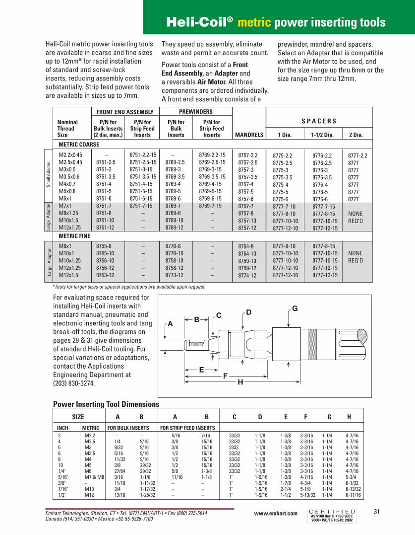
Emhart Teknologies, Shelton, CT 31 Tel. (877) EMHART-1 Fax (800) 225-5614 Canada (514) 351-0330 Mexico +52-55-5326-7100
www.emhart.com C E R T I F I E D
Heli-Coil®
M12x1.5 8753-12 – 8773-12 –M12x1.25 8756-12 – 8758-12 –M10x1.25 8756-10 – 8758-10 –M10x1 8755-10 – 8770-10 – M8x1 8755-8 – 8770-8 –
M12x1.75 8751-12 – 8769-12 –M10x1.5 8751-10 – 8769-10 –M8x1.25 8751-8 – 8769-8 – M7x1 8751-7 8751-7-15 8769-7 8769-7-15 M6x1 8751-6 8751-6-15 8769-6 8769-6-15 M5x0.8 8751-5 8751-5-15 8769-5 8769-5-15 M4x0.7 8751-4 8751-4-15 8769-4 8769-4-15 M3.5x0.6 8751-3.5 8751-3.5-15 8769-3.5 8769-3.5-15 M3x0.5 8751-3 8751-3-15 8769-3 8769-3-15 M2.5x0.45 8751-2.5 8751-2.5-15 8769-2.5 8769-2.5-15M2.2x0.45 – 8751-2.2-15 – 8769-2.2-15
8777-10-10 8777-10-15 REQ'D8777-10-10 8777-10-15 NONE
8777-10-10 8777-10-15 REQ’D8777-8-10 8777-8-15 NONE
8775-6 8776-6 87778775-5 8776-5 87778775-4 8776-4 87778775-3.5 8776-3.5 87778775-3 8776-3 87778775-2.5 8776-2.5 87778775-2.2 8776-2.2 8777-2.2
prewinder, mandrel and spacers.
components are ordered individually.
They speed up assembly, eliminate
substantially. Strip feed power tools
Heli-Coil metric power inserting tools are available in coarse and fine sizes up to 12mm* for rapid installation of standard and screw-lock inserts, reducing assembly costs
are available in sizes up to 7mm.
waste and permit an accurate count.
Power tools consist of a an and
a reversible All three
A front end assembly consists of a
Select an Adapter that is compatible with the Air Motor to be used, and for the size range up thru 6mm or the size range 7mm thru 12mm.
8757-2.2 8757-2.5 8757-3 8757-3.5 8757-4 8757-5 8757-6 8757-7 8757-8 8757-10 8757-12
8764-8 8764-10 8759-10 8759-12 8774-12
8777-7-10 8777-7-15
8777-12-10 8777-12-15
8777-8-10 8777-8-15
8777-12-10 8777-12-158777-12-10 8777-12-15
*Tools for larger sizes or special applications are available upon request.
For evaluating space required for installing Heli-Coil inserts with standard manual, pneumatic and electronic inserting tools and tang break-off tools, the diagrams on pages 29 & 31 give dimensions of standard Heli-Coil tooling. For special variations or adaptations, contact the Applications Engineering Department at (203) 830-3274.
AC D G
HF
E
B
Smal
l Ada
pter
Larg
e A
dapt
erLa
rge
Ada
pter

Emhart Teknologies, Shelton, CT 32 Tel. (877) EMHART-1 Fax (800) 225-5614Canada (514) 351-0330 Mexico +52-55-5326-7100
www.emhart.comC E R T I F I E D
Heli-Coil®
is
The Power Tool Holder 23537 Power Tool Holder
Application Note: Variations in
inserts listed below.
electric power because it is quieter.
configuration of the mandrels is preferred over air. The slender
Inserting ToolElectronic Power
Heli-Coil offers an electronic power tool where electric power
allows them to reach into constricted areas. Electric power meets the requirements of clean room operations. Operators prefer
The electronic tool is lighter to minimize operator fatigue. Mandrel assemblies are available to install the sizes of Heli-Coil bulk loaded
Mandrel Assembly dimensions and threads are available on special order to meet individual applications. For Mandrel Assemblies to meet your special conditions, please contact Heli-Coil Applications Engineering Department at (203) 830-3274.
is mounted on a bench and the appropriate air motor is attached to a spring loaded air tube at the end of a movable arm. A mounting arm also provided for attaching reels of strip-feed inserts.
This power tool holder configuration ensures accurate vertical (square to work surface) installations of Heli-Coil inserts in relatively large parts. The tool holder is capable of installing inserts within a radius of 23.5 inches as well as on planes differing by 3.5 inches. Example: Box shape configurations.
Inserting Tool.
regulator-lubricator, oil, two quick (8510-1), adapter, tools, a filter-
Pneumatic Power Tool Installation KitThis Heli-Coil power tool installation kit (8522) contains an Air Motor
disconnect fittings, and wrenches. All are packed in a portable molded box with easy-to-follow operating instructions. Front End Assemblies may be ordered separately to fit the sizes of Heli-Coil inserts to be installed.
This tool holder is recom-mended for use with the
and air tools. The tool holder also may be used with the Heli-Coil Electronic
10(.190)-24 8051-38(.164)-32 8051-26(.138)-32 8051-064(.112)-40 8051-042(.086)-56 8051-02
10(.190)-32 10089-3
CombinationSet 8520Large Adapter Set 8521 Small Adapter Set 8522
includes a driver, 2 batteries (7200-
The Heli-Coil Cordless Tool isCordless Electric Tool
a complete kit (7200) that
20), 15 minute charger and mandrel chuck all in a durable metal box. The cordless tool is portable, lightweight, has adjustable torque and uses standard Heli-Coil electronic tool installation mandrels for quick setup.

Emhart Teknologies, Shelton, CT 33 Tel. (877) EMHART-1 Fax (800) 225-5614Canada (514) 351-0330 Mexico +52-55-5326-7100
www.emhart.com C E R T I F I E D
Heli-Coil®
3 thru 8 M2.5 thru M4 1227-062 M2.2 1227-021 M2 1227-01
Right & wrong blade positions of insert extracting tool.
Tang break-off tools will break-off tangs thru 2 diameter lengths.
the standard part number (eg, 3695-01-30).
long nose pliers. Bend tang up and down to snap off at notch.
NominalThreadSize
M12x1.5 4238-12 4436-12M12x1.25 4238-12 4436-12M10x1.25 4238-10 4436-10M10x1 4238-10 4436-10M8x1 4238-8 3643-5
M12x1.75 4238-12 4436-12M10x1.25 4238-10 4436-10M8x1.25 4238-8 3643-5M7x1 4238-7 4436-7M6x1 4238-6 3697-4M5x0.8 4238-5 3697-3M4x0.7 4238-4 3697-2M3.5x0.6 4238-3 3697-04M3x0.5 4238-3 3697-04M2.5x0.45 4238-2.2 3697-02M2.2x0 45 4238-2.2 3697-02M2x0.4 4238-2 3697-01
METRIC COARSE
METRIC FINE
NominalThreadSize
10 (.190)-32 3695-3 3697-38 (.164)-36 3695-2 3697-26 (.138)-40 3695-06 3697-064 (.112)-48 3695-04 3697-043 (.099)-56 3695-02 3697-022 (.086)-64 3695-02 3697-02
12 (.216)-24 3695-3 3697-310 (.190)-24 3695-3 3697-38 (.164)-32 3695-2 3697-26 (.138)-32 3695-06 3697-065 (.125)-40 3695-04 3697-044 (.112)-40 3695-04 3697-043 (.099)-48 3695-02 3697-022 (.086)-56 3695-02 3697-021 (.073)-64 3695-01 3697-01
UNIFIED COARSE THREAD (UNC)
UNIFIED FINE THREAD (UNF)
RIGHT
and 12mm metric nominal diameter.
Break-Off ToolsHeli-Coil Tang
WRONG
The driving tangs of Heli-Coil inserts must be removed to eliminate their interference with the end of the assembled bolt. Heli-Coil tang break-off tools are available for
Their operation is automatic, having a spring loaded, easily triggered punch that strikes a sharp, uniform blow against the tang of the installed insert. The tool can be operated with one hand.
tool with a light blow. Maintaining
Extracting ToolsHeli-Coil
Occasionally Heli-Coil inserts must be removed. Inserts maybe removed manually withlittle effort. This is done byinserting the blade of the extracting tool into the Heli-Coil insert so that the V section of the blade is toward the top end of the insert. Strike the head of the
a steady pressure of blade against insert, turn the extracting tool counterclockwise until the insert is removed.

Emhart Teknologies, Shelton, CT 34 Tel. (877) EMHART-1 Fax (800) 225-5614 Canada (514) 351-0330 Mexico +52-55-5326-7100
www.emhart.comC E R T I F I E D
Hand Installation ToolingHeli-Coil Tangless
the tool. and increase the overall life of
easily for virtually any application.
end of the coil for installation. applies torque to a notch in the
the same mandrel assembly.
Tangless
Electronic tool & power supply
Hand installation tool
Strip-feed reels, available in all sizes
® inserts may be installed by hand or electronic power tooling with
Front end assemblies are also available for pneumatic power tooling.
®
TanglessHeli-Coil® ® tools
Power ToolingHeli-Coil Tangless
Installation and Removal Tools
® ***
1/4-28 .42 .63 .22 1/4-20 .42 .63 .22 10-32 .38 .51 .15 10-24 .38 .51 .19 8-32 .35 .51 .15 6-32 .32 .50 .14 4-40 .25 .40 .13
.32 .32 .09 2-56Nose Diameter Body Diameter Prewinder Tip Length
A B C Front End Assembly Dimensions
Note: Installation mandrel and adjusting/removal tool designed for use with both handle and electronic tool.
Installation Tool Dimensions
1/4-28 5.53 3.00 .370 1/4-20 5.53 3.00 .370 10-32 5.53 3.00 .370 10-24 5.53 3.00 .370 8-32 5.68 3.15 .360 6-32 5.53 3.00 .360 4-40 5.43 2.90 .240 2-56 5.33 2.80 .240
Size (reference) Length Diameter Thread Overall Length Mandrel Spinner
Nominal “A” “B” “C”
Pneumatic Installation Tools & Adapters.* An electronic driver requires a power supply, part number 8050-50.** Includes blade, spring and pin.
*** For use with Heli-Coil ®
Front End Assembly
.375
B
.164
Installation mandrel only
2.25
.250
Nominal
.562
A
Adjusting/removal tool (shown w/o handle)
Installation mandrel w/handle assembly
Size Assembly Assembly Blade Thread Front End Mandrel Replacement Nominal Replacement
1/4-28 18552-4-15 18552-4-30 18552-4-2 10-32 18552-3-15 18552-3-30 18552-3-2 1/4-20 18551-4-15 18551-4-30 18551-4-2 10-24 18551-3-15 18551-3-30 18551-3-2 8-32 18551-2-15 18551-2-30 18551-2-2 6-32 18551-06-15 18551-06-30 18551-06-2 4-40 18551-04-15 18551-04-30 18551-04-2 2-56 18551-02-15 18551-02-30 18551-02-2
Thread Installation Tool Blade Kit** (with handles) Driver* Hand Replacement Installation Removal Tool Electronic Nominal
1/4-28 17552-4 N/A 17552-4-5 7572-4-5 7570-4 8050-650C10-32 17552-3 7572-3 17552-3-5 7572-3-5 7570-3 8050-650C1/4-20 17551-4 7571-4 17551-4-5 7571-4-5 7570-4 8050-650C10-24 17551-3 7571-3 17551-3-5 7571-3-5 7570-3 8050-650C8-32 17551-2 7571-2 17551-2-5 7571-2-5 7570-2 8050-400C6-32 17551-06 7571-06 17551-06-5 7571-06-5 7570-06 8050-400C4-40 17551-04 7571-04 17551-04-5 7571-04-5 7570-04 8050-400C 2-56 17551-02 7571-02 17551-02-5 7571-02-5 7570-02 8050-400C
C
8050-400C
8050-50
Size Crank Style Gauge Style Crank Style Gauge Style

Emhart Teknologies, Shelton, CT 15 Tel. (877) EMHART-1 Fax (800) 225-5614Canada (514) 351-0330 Mexico +52-55-5326-7100
www.emhart.com C E R T I F I E D
Metric 4937-150 M5x0.8, M6x1, M8x1.25, M10x1.5Metric 4937-125 M5x0.8, M6x1, M8x1.25, M10x1.25Inch Fine 4936 10-32, 1/4-28, 5/16-24, 3/8-24, 7/16-20, 1/2-20Inch Coarse 4934 1/4-20, 5/16-18, 3/8-16, 7/16-14, 1/2-13, 5/8-11
1-11-1/2 5407-16 63/4-14 5407-12 101/2-14 5407-8 103/8-18 5407-6 101/4-18 5407-4 121/8-27 5407-2 12
Size Part No. Per Kit
Thread Inserts
Long 6M14x1.25* 5408-14 Normal 6
Short 6
.472 6
SPARK PLUG SERIES
M18x1.5 5406-18 6M16x1.5 5406-16 6M14x1.5 5406-14 6
M20x2.5 5403-20 4M18x2.5 5403-18 6M16x2 5403-16 6M14x2 5403-14 12
M11x1.5 5403-11 6
M9x1.25 5403-9 12
Size P/N per Kit
Thread Kit Inserts
1–1/2-12 5528-24 41–3/8-12 5528-22 41–1/4-12 5528-20 4
–1/8-12 5528-18 51-12 5528-161 61-14 5528-16 67/8-14 5528-14 63/4-16 5402-12 45/8-18 5402-10 69/16-18 5402-9 6
1–1/2-6 5521-24 41–3/8-6 5521-22 41–1/4-7 5521-20 41–1/8-7 5521-18 51-8 5521-16 67/8-9 5521-14 63/4-10 5401-12 45/8-11 5401-10 69/16-12 5401-9 6
Size P/N per Kit
Thread Kit Inserts
wear, corrosion and over-torque.
Heli-Coil inserts are available in thread repair kits and sets for repairing tapped holes which have been stripped or damaged due to
They are available in inch, metric, spark plug and pipe thread series.
Inch Coarse Thread (UNC)
4-40 5401-04 36*5-40 5401-05 36*6-32 5401-06 36*8-32 5401-2 36*10-24 5401-3 36*12-24 5401-1 36*1/4-20 5401-4 36*5/16-18 5401-5 36*3/8-16 5401-6 18*7/16-14 5401-7 18*1/2-13 5401-8 18*
Inch Fine Thread (UNF)
6-40 5402-06 36*8-36 5402-2 36*10-32 5402-3 36*1/4-28 5402-4 36*5/16-24 5402-5 36*3/8-24 5402-6 18*7/17-20 5402-7 18*1/2-20 5402-8 18*
1
All kits have a quantity of inserts, the proper size drill, high speed steel Heli-Coil tap and an installation tool. The Professional Kits* (shown in bold type) also includes a tang removal tool and quantities of three lengths of inserts.
Metric Coarse
M3x0.5 5403-3 36*M3.5x0.6 5403-3.5 36*M4x0.7 5403-4 18*M5x0.8 5403-5 18*M6x1 5403-6 18*M7x1 5403-7 18*M8x1.25 5403-8 18*
M10x1.5 5403-10 18*
M12x1.75 5403-12 18*
Metric Fine
M8x1 5404-8 18*M10x1 5404-10 18*M10x1.25 5405-10 18*M12x1.25 5405-12 18*M12x1.5 5406-12 18*
PIPE THREAD SERIES
All sets contain a drill, tap, tool and inserts for each size listed above.
MASTER THREAD REPAIR SETS
* The total quantity of inserts in the Professional Kits represents 3 lengths.
* The total quantity of inserts in the Professional Kits represents 3 lengths.
(*)Sav-A-Thread®

www.noblefix.com
New Delhi – 110019 INDIA Raja House , 30-31 Nehru Place,
HELI- COIL SALES & TECHNICAL SUPPORT
ASIA – INDIA Noble Aerospp Limited Private cea307
Phone : +91-11- 41617246 , +91-11- 41617274 FAX : +91-11- 41617271 E-Mail : [email protected] Website :
ade Mark Of Emhart Teknologies Inc., Worldwide Heli-Coil is a Registered Tr
Shelton , CT 06484 USA P.O. Box 859 50 Shelton Technology Center Industrial Division Emhart Teknologies