hello, and welcome to this presentation of the nested...
TRANSCRIPT

Hello, and welcome to this presentation of the Nested Vector Interrupt Controller –or NVIC – module for Kinetis K series MCUs. In this session, you’ll learn about the NVIC, its main features and the application benefits of leveraging this function.
0

In this presentation, we’ll cover:
• An overview of the NVIC module itself
• The on-chip interconnections and inter-module dependencies
• Software configuration
• And some frequently asked questions
1
Let’s first begin with an overview of the module.
2

NVIC Module Features and Application Benefits
Features
•The NVIC module is located within the ARM® Cortex®-M4 core and provides low latency interrupt servicing by taking only 12 clock cycles to start or exit the interrupt service routine, or ISR. In case there are two pending interrupts, it will take 6 clock cyclescycles
• There are up to 120 interrupt sources on the NVIC implementation for Kinetis devices. The first 16 interrupt sources are dedicated to the ARM Cortex-M4 core
• The NVIC module supports up to 16 interrupt priority levels for peripherals. However, the priority level for the ARM Cortex-M4 core exceptions are fixed
Application benefits, include:
• Automatic nested interrupt support is provided for embedded systems, so low priority interrupt requests are delayed when high priority requests are pendingpriority interrupt requests are delayed when high priority requests are pending
• The vector table can be relocated from Flash to RAM for applications such as bootloaders
3

Exception Stacking
Exceptions are the interrupts that come from the core. Kinetis K MCUs are based on ARM® Cortex®-M4 cores.
When an exception is triggered, the ARM Cortex-M4 processor will start the exception process where 8 registers are pushed onto the stack before fetching theexception process where 8 registers are pushed onto the stack before fetching the ISR address.
The XPSR is the processor status register and it contains the ALU flags, execution status, and the currently executing interrupt number.
You may be asking, why these 8 registers? The answer is: These registers are the ones used by the compiler to pass parameters to C functions. Because of this, the ISR handlers are common C functions, and no compiler directive or special instructions are necessary, such as RTI or RTE.
4
Tail Chaining
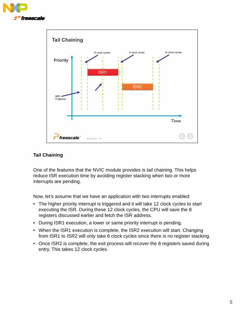
One of the features that the NVIC module provides is tail chaining. This helps reduce ISR execution time by avoiding register stacking when two or more interrupts are pending.
Now let’s assume that we have an application with two interrupts enabled:Now, let s assume that we have an application with two interrupts enabled:
• The higher priority interrupt is triggered and it will take 12 clock cycles to start executing the ISR. During these 12 clock cycles, the CPU will save the 8 registers discussed earlier and fetch the ISR address.
• During ISR1 execution, a lower or same priority interrupt is pending.
• When the ISR1 execution is complete, the ISR2 execution will start. Changing from ISR1 to ISR2 will only take 6 clock cycles since there is no register stacking.
• Once ISR2 is complete, the exit process will recover the 8 registers saved during entry. This takes 12 clock cycles.
5

Preemption
Preemption allows a higher priority ISR to execute by interrupting a lower priority ISR.
Let’s consider a case where there is a low priority ISR being executed when a higher priority interrupt is triggered:higher priority interrupt is triggered:
• At this point, the CPU will stop executing ISR1 and go to ISR2. However, please note that in order to return to ISR1, the registers must be saved, hence, it takes 12 clock cycles to start ISR2.
• When ISR2 is complete, ISR1 resumes execution.
6
Masking Priorities
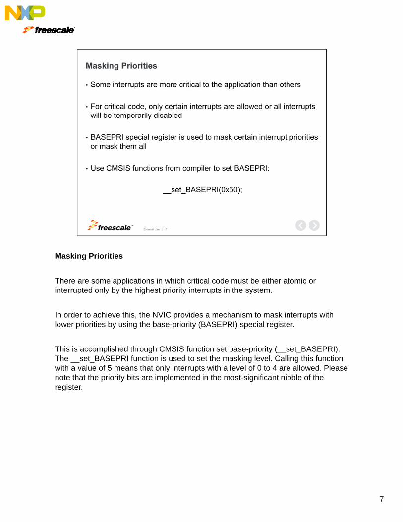
There are some applications in which critical code must be either atomic or interrupted only by the highest priority interrupts in the system.
In order to achieve this, the NVIC provides a mechanism to mask interrupts with lower priorities by using the base priority (BASEPRI) special registerlower priorities by using the base-priority (BASEPRI) special register.
This is accomplished through CMSIS function set base-priority (__set_BASEPRI). The __set_BASEPRI function is used to set the masking level. Calling this function with a value of 5 means that only interrupts with a level of 0 to 4 are allowed. Please note that the priority bits are implemented in the most-significant nibble of the registerregister.
7

Fault Exceptions
Within the first 16 interrupt sources, there are four fault exceptions that are useful for debugging issues.
The fault sources within the ARM® Cortex®-M4 core are:
• Usage fault
• Bus fault
• Memory management fault
• Hard fault
Each of the fault exceptions has its own interrupt vector, allowing you to choose the cause of the fault in your system. Only the hard fault exception is enabled out of reset, and is triggered for usage, bus, or memory management faults until those exceptions are enabled explicitly in the system control block register.
8

SysTick
The NVIC module provides a 24-bit timer called SysTick, which can be used as a time base for the real-time operating systems , or as a system time base for periodic tasks in a bare metal environment.
On Kinetis MCUs, the calibration feature of SysTick is not available because the timer clock source is fixed to use the processor core clock. There is no option for an external reference.
9

Now, let’s talk about on-chip interconnection and inter-module dependencies.
10
NVIC Interconnections and Inter-module Dependencies
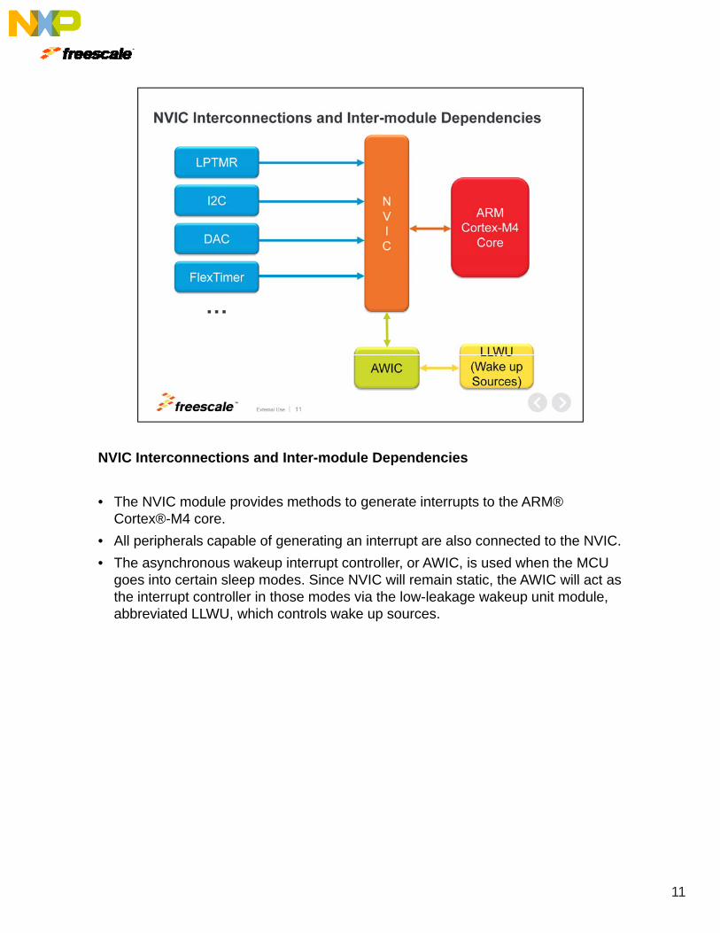
• The NVIC module provides methods to generate interrupts to the ARM® Cortex®-M4 core.
• All peripherals capable of generating an interrupt are also connected to the NVIC.
• The asynchronous wakeup interrupt controller, or AWIC, is used when the MCU goes into certain sleep modes Since NVIC will remain static the AWIC will act asgoes into certain sleep modes. Since NVIC will remain static, the AWIC will act as the interrupt controller in those modes via the low-leakage wakeup unit module, abbreviated LLWU, which controls wake up sources.
11

Now, software configuration.
12

Kinetis SDK (KSDK) Interrupt Enabling
The Kinetis SDK provides peripheral drivers that implement interrupt handling. It also provides an API to enable interrupts for the NVIC.
In the following example, we enable a low-power interrupt, set the interrupt priority, and create an interrupt handler placeholder:and create an interrupt handler placeholder:
• First, you’ll need to include the Kinetis SDK interrupt manager header file since this provides necessary APIs.
• The enable IRQ API passes in the peripheral IRQ number via a parameter. For ease of use, Kinetis SDK provides an interface to the IRQ number that is ARM® Cortex®-M4 core CMSIS compliant.
• Configuration of the interrupt priority is left to the application and the ARM® Cortex®-M4 core CMSIS API must be used. In this example, the timer is set to priority 5.
• Finally, implement the ISR handler with the required processing and application specific tasks.
13

Kinetis SDK (KSDK) Enabling Faults
Now here’s an example on how to enable all the faults:
• The Kinetis SDK does not provide an interface to the system control block, or the SCB, which means that the registers must be written by the application. So first, enable the required faults In this example all faults are enabledenable the required faults. In this example, all faults are enabled.
• The fault handlers are not implemented because these are application specific. The application must implement them and add the desired processing based on its needs.
14

Finally, some frequently asked questions.
15

NVIC FAQs
Q: Can I disable non-maskable interrupt?
A: Yes, the NMI signal is multiplexed on a GPIO and is the default function for that pin.
NMI is active low and is level sensitive with priority -2. This means the only exception capable of interrupting it is a system reset. The NMI signal is available after CPU reset, so if the pin is connected to a signal that is on logic ‘0’, the NMI ISR will be triggered continuously until the pin is logic ‘1’, which can cause a system lockup.
NMI functionality can be disabled by clearing the NMI_disable bit in the Flash options register.
Q: Do I need to clear the NVIC pending interrupt in my ISR?
A: No, the pending interrupt in the NVIC is cleared automatically when the interrupt is serviced. However, you may need to clear the condition causing the interrupt foris serviced. However, you may need to clear the condition causing the interrupt for the specific peripheral.
16

References
The application note listed here outlines the role of the NVIC with Kinetis MCU Power Management. Chapter 3 of the Kinetis Quick Reference Guide provides a more in depth look at the NVIC module.
For more information we invite you to also visit us on the web atFor more information, we invite you to also visit us on the web at Freescale.com/Kinetis and check out our community page.
17

18