henrik malm2 of a mega space frame stamatios psarras...
TRANSCRIPT
620
The Computational Challenges of a Mega Space Frame
Martha TsigkariJens Olsson1 Henrik Malm2 StamatiosPsarras Francis AishFoster + PartnersShaping the Envelope of New Mexico City Airport
1
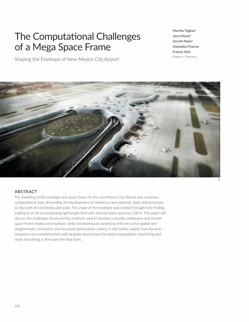
ABSTRACTThe modeling of the envelope and space frame for the new Mexico City Airport was a massive computational task, demanding the development of numerous new methods, tools and processes to deal with its complexity and scale. The shape of the envelope was created through form finding, leading to an all-encompassing lightweight shell with internal spans reaching 130 m. This paper will discuss the challenges faced and the methods used to develop a visually continuous and smooth space-frame model and envelope, while simultaneously complying with very strict spatial and programmatic constraints and structural optimisation criteria. It will further explain how dynamic relaxation was complemented with bespoke mechanisms for mesh manipulation, interfacing and mesh smoothing to fine-tune the final form.

621ACADIA 2017 | DISCIPLINES + DISRUPTION
3
INTRODUCTIONThe intent behind the development of the new Mexico City airport's envelope was to create an all-encompassing continuous space frame that covers the complete terminal building. To create this massive space frame, form finding was applied by embracing and extending the same principles used for La Sagrada Familia and the British Museum Great Court roof. The development of such a structure posed an array of challenges, not only due to its unconventional shape, but also to its size and strict programmatic and structural requirements.
As a start, this paper will briefly present the British Museum roof as a precedent project. An overview will then be given of the challenges of the project, which drove, constrained and shaped the development of the space frame. The ways in which structural analysis informed the process will also be mentioned. Subsequent sections will delve further into the details of the important milestones in that process, such as the representation of the space frame via a 3D mesh model, the development of this model’s seed topology, the form finding via dynamic relax-ation (DR), the development of bespoke mesh smoothing tools and integration and interfacing with pre-rationalised parts.
THE BRITISH MUSEUM AS A PRECEDENTThe most influential precedent in the development of the process described in this paper was the British Museum (BM) Great Court roof. Many design aspirations, like seamless gridding, lightweight appearance, fluid form, etc., were developed with this project in mind. Many design solutions can be traced back to the process described by Chris Williams (2001), including the defini-tion of the shape via a mathematical formula (in the BM case via an analytical function), the initiation of a structural grid defining the mesh topology, and the process of dynamically relaxing the grid by sliding the nodes of the mesh to reduce discontinuities (Figures 2 and 3).
CHALLENGESScaleFrom one end to the other, the doubly curved space frame of the airport reaches 1.6 km. The entire envelope is self-supporting, its weight carried by its undulating perimeter and 21 funnels that transfer forces to the ground foundation. Each funnel is of a similar shape and size to the British Museum roof (see Figures 4 and 5 for a comparison), and the maximum span between two funnels is approx. 130 m. The envelope can be accessed from three entry arches with a span of 115 m each. These lead into a 100 m span canopy, under which a road with an arc length of almost 0.5 km passes through. In total there are around ¾ million bars comprising the two-layer space frame.
2 British Museum, Initial Grid
2
3 Relaxed Grid (both Williams 2001)
ConstraintsApart from the sheer size of the space frame, there were challenges associated with the setting out, form finding and manipulation of the mesh model representing the space frame. The geometry was conceived as a dynamically relaxed (DR), structurally optimal shape. DR processes are very sensitive to the initial input geometry of the mesh model and its topology, the forces applied and the variable rest lengths and stiffness of the system. This had to be further related to geometric requirements for symmetry and for the space frame to node out evenly on interfacing façades and floor plates. It also had to comply with internal and external programmatic constraints and construc-tability requirements, which minimised the degrees of freedom of the entire system. The constraints model (Figure 6) was the driver for the entire process and defined all the basic inputs for the space frame initialisation, such as boundary conditions and funnel locations, as well as clearance areas dictated by, for example, structural, circulation (people/baggage), MEP and secu-rity requirements.
Equally important was the visual continuity and smoothness of the mesh. The lines of the space frame needed to flow effort-lessly throughout the roof without visible kinks or discontinuities. This meant that a process had to be established to provide full

622
control of any potential discontinuity and location of odd-va-lence nodes (nodes with an odd number of elements coming to it). Visible seams were unacceptable. All load paths had to be uninterrupted to ensure optimal transfer of all forces to the foundations. The continuity was especially challenging at the interfaces with separately modeled standardised parts, such as the perimeter and the Fix Link Bridges (FLBs), where a seamless transition with the dynamically relaxed parts was required.
Finally, a data retention algorithm had to be written for the topology of the nodes and panels in order for their sorting and indexing to be preserved throughout the sequence of mesh manipulations. This was pursued because of the need to, for example, place sky lights in particular patterns across the enve-lope. This algorithm is, however, not in the scope of this paper.
Structural ConsiderationsThe project posed a lot of structural challenges. The space frame sits on the site of a drained lake, which has very soft soil that recedes each year in variable percentages throughout the plot. In addition, the area is highly seismic, and there is a volcano nearby that discharges ash that quickly solidifies with water. Therefore, the design had to be very closely coordinated with the structural engineers, leading to requirements regarding topology, element concentration, strut-length binning and space frame angles. The structural analysis fed back into the mesh manipulation proce-dures and directly affected the topological manipulations, DR settings and the bespoke smoothing algorithms.
DEVELOPINGTHESHELLGEOMETRYOutline of the ProcessIn the process of shaping the roof geometry, much of the work revolved around achieving strict control over the shape while driving parts of it with a form-finding simulation.
The form finding was initially applied to a planar configuration, but as the design got more refined, this approach was inade-quate both in terms of control and precision, as it was difficult to resolve the node distribution in the planar state to ensure an even enough distribution after the simulation was performed. This was particularly problematic in highly stressed areas like the columns and the perimeter. Another issue was the lack of control achieved in relation to planning constraints. Early attempts were made to manipulate the distribution of forces applied on the mesh, but the end result was a process that did not ensure the level of control and accuracy needed for a successful outcome.
4, 5 Size of the terminal compared to the roof of the British Museum Great Court.
6 Simplified constraints diagram
7 Voronoi configuration for M2D
8 Standardised perimeter geometry
6
TheComputationalChallengesofaMega-SpaceframeTsigkari, Olsson, Malm, Psarras, Aish
54

623ACADIA 2017 | DISCIPLINES + DISRUPTION
These issues lead to the development of a process for which the pre-form-found geometry was modelled in 3D and split in three parts: (i) the standardised side geometry (including the fixed link bridges [FLBs]), which remains unchanged during the form-finding process; (ii) the torso that was sculpted in 3D using a set of constraint-driven functions; and (iii) the funnels that were modelled as a continuous extrusion of the roof down to the ground. The procedure of setting up the topology and the pre-form-finding geometry, as well as a description of the form-finding process and the smoothing, is listed below in 10 steps.
1. 2D topology M2D
2. Standardised mesh for the sides MS
3. The fixed link bridges MFLB
4. The funnels MF
5. 3D torso geometry M3D
6. Form finding of M3D+MF creating MDR
7. Mesh stitching, M=MS+MDR
8. Smoothing M using optimal Delaunay triangulation (ODT)
9. Plugging in and blending standardised parts (such as MFLB.) with M.
10. Tetrahedral configuration for double space frame–variable offset from
cladding layer
2D Topology (M2D)Two inherently different methods were developed and evaluated for the topology of the roof structure. Both were initialised in 2D as a subdivision scheme to allow for density control but with different characteristics in terms of geometric patterning, struc-tural efficiency and buildability.
The first topology strategy was based on a Voronoi diagram (Figure 7), where the cells are centred around the circular columns and results in a topology similar to that of the British Museum Great Court Roof. However, this was outperformed by another approach, based on a primal triangle quadrisection
(PTQ) subdivision scheme, both in terms of smoothness but also in terms of structural efficiency. The latter scheme is agnostic to the column positions, and thus allows for a more even element size distribution. The structural efficiency, being driven largely by the weight of the space frame, made it crucial to keep the angles between adjacent elements as close to 60° as possible to ensure that the nodes are kept at minimum size, effectively minimising their weight. The triangular scheme also meant a reduction of odd valence nodes, allowing for an even patterning of roof lights and a sense of continuity throughout the grid that makes the building appear seamless.
Standardised Perimeter Geometry (MS)There were three important drivers behind the need for stan-dardised side geometry: a) the curvature on the edge needed to be very particular to comply with planning requirements, b) it needed to accommodate for a seamless transition from the roof to the standardised FLBs and c) since it comprised the largest area clad with a gasket system, panel repetition was found important to cut costs.
In order to acquire control over the edge condition, a rationalised planar setting-out was developed based on arc segments. By then sweeping another arc segment along this planar curve, the edge condition could be defined as a series of torus patches, which, when panelised, allowed for both horizontal alignments to the floorplates (at +6.30 m and +12.30 m) and repetition of panel sizes in the sweep direction (Pottmann et al. 2007). Furthermore, the end-caps for the four piers were modelled using geodesic domes, joining each of the two sides together into a continuous strip, from here on referred to as MS (Figure 8).
The Fixed Link BridgesAn important part of the standardised geometry for the terminal is the fixed link bridge (FLB). These are seamlessly integrated
7 8

624
into the airport building and lead passengers and crew to and from the airplanes at every gate location. There are 46 of these FLBs at this airport and they are all modelled using the same mirror-symmetric geometry along their main axis, with the same triangulation, which consequently leads to a reasonable level of panel repetition.
The big challenge of modelling the envelope of the FLBs was to comply with the very restrictive external and internal constraints, leaving very tight volumes to design within. Ultimately, a single final standardised FLB geometry, MFLB, was developed, which was then adaptively oriented and inserted at every gate location using an automated process that locally adjusted MFLB to inter-face smoothly with the standardised perimeter geometry MS.
Because of the large local curvature of the FLB geometry in relation to the relatively large triangle panel sizes, a specific mesh-offsetting algorithm was implemented in order guarantee a certain minimal distance between the outer cladding layer and the inner structure layer. This method offset every vertex of the original mesh along the local average face normal in a calculated variable distance that guarantees a minimal distance between the original and the offset mesh faces (Figure 9).
The Funnels (MF)The perimeter of the building and the 21 funnel-shaped columns carry the whole weight of the roof to the foundations and provide lateral stiffness in the case of a seismic event. The funnel shape can be described as a double-curved truncated cone with a continuously curving transition, such that the connection to the ground is perpendicular and the connection to the roof is tangential prior to the form finding. The final shape of the funnels is determined by the form-finding simulation, which makes precision a challenge and the shaping an iterative process. As the only structural element to protrude through the floor slabs, the funnels need to comply with a range of constraints, including symmetry, alignment to the façade at the entrance, noding out with the foundation structure, as well as manu-facturing constraints (e.g., angle restrictions for welding). The
difference in span (between funnel–funnel and funnel–edge) resulted in a slight leaning of the funnels after the form finding, expressing the structural function and the funicular nature of the geometry. However beneficial in terms of formal expression, the leaning was causing problems with drainage and significant effort went into minimising the negative slope, causing the water to flow uncontrollably.
3DTorsoGeometry(M3D)
To shape the pre-form-finding torso geometry, a set of mathe-matical mapping functions were defined to compute the z-value (height) of each of the nodes in M2D. These functions map the planar relationships between the vertices in M2D and their surrounding constraints in three steps, where
zp (d) is the shape function setting the torso mesh starting height and ensuring a smooth transition to the standardised side geometry, zf (d) is the shape function used for the column interface condition and zr (d,p) is the shape function used to control the lateral curvature of the roof.
See Figure 10 for a visualisation of these three shape functions and their effect on the roof shape. The colour scheme indicates the amount of height change that is created by each function. The functions are based on Bezier equations and linear mapping. Superimposing the three functions gives the vertex positions for the nodes in M3D according to:
vi (x,y,zp (di;e)+zf (di;c)+zr (di;r,pir)), (1)
where vi (x,y,z) is the initial position of vertex i in M2D, di;e is the shortest distance from vi to the edge, di;f is the shortest distance from vi to the closest funnel centre point, di;r is the shortest distance from vi to any ridge curve, and pi
r is the parameter for the closest point on the closest ridge curve.
See Figure 11 for a visualisation of these entities.
From a form-finding perspective, but also from a constraints point of view, there are two significantly different conditions of how the roof meets the ground, expressed in the shaping of the side geometry, the funnel geometry and the formulation of the shape functions zp (d) and zf (d). This is further elaborated in the following sections. 9 The developed Mesh Offset method for the FLB geometry.
TheComputationalChallengesofaMega-SpaceframeTsigkari, Olsson, Malm, Psarras, Aish

625ACADIA 2017 | DISCIPLINES + DISRUPTION
The Perimeter Edge Condition – zp (d) The absence of double curvature as the roof comes to the perim-eter and the variation of span between funnels and edge posed challenges in achieving a form that would respect the constraints in this area. The large horizontal thrust resulted in a perimeter roof–ground angle that didn’t comply with spatial and program-matic requirements. Thus, the perimeter geometry had to be locked in the form finding, and the shape function zp (d) was tuned to achieve a smooth blending between the standardised and the form-found geometry (Figure 12).
The function zp (d) is based on the equation of a cubic Bezier curve written below as a linear combination of two quadratic Bezier curves, BP0,P1,P2(t) and BP1,P2,P3(t). To simplify implementation, di;e in (de
min,demax) is mapped to t in (0,1) via t = e(d) so that the
shape function becomes
zp (t)= (1–ti )BP0,P1,P2 (ti )+ ti BP1,P2,P3 (ti ), 0 ≤t<1, (2)
where P0,P1,P2,P3 are the points defining the shape of the Bezier curve, positioned to achieve the sought blending effect,
demin is the minimum distance from any vertex
v to the closest point on the edge, de
max is the maximum distance from any vertex v to its closest point on the boundary, and ti is the parameter on the Bezier shape function calculated as e(de
i ).
The Funnel Edge Condition – zf (d)The shaping of the roof as it transitions into the funnel is made using the zf (d) shape function and sets the premises for the column shape by defining the tangential constraints (Figure 13). The double curvature of the funnels, together with the topolog-ical arrangement of elements forming hoops, was found to be structurally beneficial for achieving a relative vertical shape that respects the planning constraints without the need for locking the geometry in the form-finding process. The pre-form-found funnel geometry, MF , is shaped partly using the zf (d) shape function and partly by parametric modeling, ensuring tangent continuity. Compared to the perimeter condition, a more vertical shape could be achieved for the funnels due to the effect of the hoops, without the need of locking the geometry in the form-finding process. The difference in span, support conditions and loading in the form-finding process induced the leaning effect on the funnels.
In analogy with zp (d), function zf (d) is also defined as in Equation (2) using cubic Bezier curves,
where P0,P1,P2,P3 are the points defining the shape of the Bezier curve, df
min is the minimum distance from any vertex v to the closest funnel centre point, df
max is the maximum distance from any vertex v to its closest funnel centre point, chosen such that no single vertex falls in the domain of two different funnels ti is the parameter of the Bezier shape function calculated as e(df
i).
See Figure 14 for a visualisation of these entities.
10 From left to right, the effect of the shape functions zp (d), zf (d) and zr (d). Red indicates small and green indicates a big change in height induced by the function.
11 Visualisation of vi, di;e, di;c and di;r

626
Shaping the Curvature of the Roof – zr(d,p) In addition to shaping the columns and the perimeter, a third function was used to control the undulation of the roof between the columns. This was particularly important in the y-direction, for which there is no direct path connecting the two funnels. This means that the stiffness properties along the y-direction are substantially different from those on the x-direction, resulting in less curvature in the form-found mesh. This third function recti-fies that by further manipulating the nodes' z height, accordingly (Figure 15).
The process involved drawing reference curves between the funnels, where more curvature was desired. These curves where used in a similar manner as in the previous two functions, by measuring the distance to each node. In addition, this function also takes into consideration the parameter of the curve on which the closest point is located (Figure 16). Different weights were used based on the direction—either x or y—of the reference curves because of the variation in stiffness.
Also, a parameter ti in (0,1) was used for each node. The ti value was mapped using a parabolic equation, so that values near the
start and end of the reference curve would be more affected than values near the middle of the domain. Again any vertex xi
with distances dri in (dr
min,drmax) is mapped to t in (0,1).
Therefore, we have
zr (t,p)=–(1–t)zmaxR(p), (4)
where zmax is maximum magnitude of movement, given different values for the two groups of ridge curves. p is the parameter of the closest point at the ridge curve, p in (0,1).
Function R(p) is used as scale factors to shape the geometry along the length of the ridge curve. Here defined as a parabola explicitly written as:
R(p)= 4p–4p2, 0 ≤p<1 (5)
Figure 17 shows pre-form-found geometry, after the three shape functions zp (d), zf (d) and zr(d) have been applied and matched
12 The zp (d) function raises the planar mesh and is blended with the standardised side mesh. The dashed lines in the background showing the natural funicular shape and the problem with the roof-ground angle.
13 The zf (d) domain, the tangential edge condition and the separate funnel mesh in light green.
14 Visualisation of vi, dfmin, d
fmax and di;f
15 Detail of the shape of the roof before (above) and after (below) applying function z r(d,p).
16 Visualisation of vi, drmin, d
rmax and di;r
12
13
14 16
TheComputationalChallengesofaMega-SpaceframeTsigkari, Olsson, Malm, Psarras, Aish
15

627ACADIA 2017 | DISCIPLINES + DISRUPTION
with the standardised geometry and parametrically modeled funnels. Compare with Figure 18, showing the geometry after form finding.
FORMFINDING(MDR)The site is located in an area with heavy seismic activity, thus the governing load case for the structure is lateral. This is a fact that is conceptually challenging to the conventional form-finding approach, where the form-driving load case at least resembles that which would govern the dimensioning of the elements. Even so, a conventional self-weight type of load case with a reversed gravitational field was applied in the form-finding process for this project. The doubly curved nature of the resulting geometry, as well as the iterative process of shaping the 21 funnel-like columns in response to structural analysis feedback, was found to provide enough stiffness for lateral loading, making for a struc-turally efficient end result.
The following form-finding load case was worked out as a compromise between structural performance, planning constraints and geometric continuity.
1. A gravitational load as a constant N/m2 force was applied to all the nodes in the form-finding domain of the mesh
2. A pressure load, shown as Ps in Figure 19 was applied on the interface with the sides, where the mesh transitions from the form-found domain to the standardised domain.
3. Patches of pressure load were applied in areas where extra curvature was desirable.
MESH SMOOTHINGAfter the form-finding and additional mesh manipulations have been performed, some of the elements have stretched, effectively introducing element size variability and discontinuities. Due to the small curvature of the global geometry and the
relative fine meshing, the nature of these discontinuities is more evident in the tangent plane of the mesh, as opposed to the normal direction of the mesh. Hence, the aim of the smoothing was to redistribute the nodes on the already fixed form. Initial smoothing attempts were made using Laplacian smoothing, which was found to have problems with valence sensitivity. A vertex with a valence <6 was found to attract adjacent vertices resulting in smaller adjacent triangles, and a vertex with a valence >6 was found to repel adjacent vertices, resulting in larger adjacent triangles. This issue was creating a discontinuity of the geometry where the odd valence nodes became more evident.
ODT SmoothingIn order to tackle the problem of valence sensitivity a modified version of optimal Delaunay triangulation (ODT) smoothing, introduced by Chen and Xu (2004) was implemented. If Delaunay triangulation is defined as the method that minimizes the inter-polation error among all other similar schemes with the same set of vertices, ODT aims to equidistribute the edge length by iteratively moving the mesh vertices in its local patch to reduce the interpolation error (Figures 20 and 21). The optimal position of the vertex can be calculated as the weighted average of neigh-bouring triangles circumcentres (Chen, Long. 2004).
Our implementation of the ODT smoothing uses half-edge mesh topology and included a couple of particular constraints that were needed for the project at hand. Among these constraints were allowing vertices to slide on constraint meshes and curves, and completely fixing vertices. Below the procedure is summarised in pseudo-code:
17
18 19
17 The resulting pre-form-found geometry consisting of a) the standardised sides, b) the torso mesh, shaped using the three shape functions and c) the para-metrically modeled funnels that are locally adapted to given constraints whilst ensuring tangent continuity with the rest of the mesh. Minput=MS + M3D + MF
18 The form-found geometry, after applying the loading scenario, described in the text, to Minput .
19 A section through two funnels and the dome, at the largest span's location. The form-found domain of the mesh is loaded with gravity PG, a pressure load PP is applied to the dome, and another pressure load PS is applied to the sides, where the mesh transitions to its fixed perimeter condition.

628
1. Assign constraints to the mesh vertices based on proximity to
constraints geometry (meshes, curves and points).
2. Assign any x, y, z movement constraints to the vertices.
3. Iterative loop performing the smoothing
For each vertex vi in the mesh:
• Extract neighbouring faces from half-edge topology.
• For each of the neighbouring faces calculate the
circumcentre.
• Calculate the average circumcentre point m.
• Calculate the movement vector w=m–vi.
• Finally, the new vertex position is given as vi*=γw,
where γ is a percentage of movement.
• Apply constraints.
• Update the mesh with the new vertex positions.
• Check convergence criteria.
CONCLUSIONThis paper shows that the discipline of computational design has become a completely essential part of the architectural model-ling of some of the largest and most innovative structures in the world, in this case the new Mexico City Airport. This particular project would not have been possible to realise without the development of new computational methods, custom tools and bespoke processes that made it possible to manage the project’s complexity, scale, strict spatial and programmatic constraints and structural challenges. Especially regarding the latter, the realisa-tion would have been impossible without very close collaboration between the architects, computational designers and engineers, disrupting the clear boundaries between the disciplines.
The various challenges in this project, with the overall aim of creating a visually smooth and continuous space frame have been presented in detail throughout the paper. Topics that were analysed in depth include: topology strategies, creation of standardised geometries and seamless interfaces, the dynamic relaxation process and application of smoothness algorithms.
The process as described has helped the team to develop a stan-dardised suite of tools to deal with complex space frames. The tools have already been used in an array of projects, but there are a lot of opportunities for improvement. One of the steps that could be revised and automated would be the 2D topology generation for complex boundary conditions. Currently this is semi-automated and requires some hands-on manipulation, particularly regarding the number and location of discontinuities. Furthermore, the authors have worked on stitching variable meshes and ensuring continuity for particular parts of the envelope (e.g., between MF and MS), but there is an opportunity there for further generalising this process, satisfying mesh and curvature continuity. Also, the use of Databased for data/meta-data retention and exchange between different disciplines could be further evolved.
REFERENCESAlliez, Pierre, David Cohen-Steiner, Mariette Yvinec, and Mathieu Desbrum. 2005. “Variational Tethrahedral Meshing.” ACM Transactions on Graphics 24 (3): 617–625.
Chen, Long. 2004. “Mesh Smoothing Schemes based on Optimal Delaunay Triangulations.” In Proceedings of the 13th International Meshing Roundtable, 109–120. Williamsburg, VA: IMR.
Chen, Long. 2007. “Optimal Delaunay Triangulation.” Presentation at the 10th Society for industrial and Appiled Mathematics Conference on Geometric Design and Computing. Irvine, CA: SIAM.
Chen, Long, and Jin-Chao Xu. 2004. “Optimal Delaunay Triangulation.” Journal of Computational Mathematics 22 (2): 2990308.
Gavrilova, Marina, ed. 2008. Generalized Voronoi Diagram: A Geometry-Based Approach to Computational Intelligence. Cham, Switzerland: Springer.
Pottmann, Helmut, Andreas Asperl, Michael Hofer, and Axel Kilian. 2007. Architectural Geometry. Vienna: Bentley Institute Press.
Shewchuk, Jonathan. 1998. "Re: circumsphere."
20
21
The Computational Challenges of a Mega-Spaceframe Tsigkari, Olsson, Malm, Psarras, Aish
20 Diagram showing the local patch for node xi and its neighbouring vertices before and after the new position xi * is calculated (Chen 2007)
21 From left to right: Original mesh, Laplacian Smoothing, ODT Smoothing (Chen and Xu 2004)

629ACADIA 2017 | DISCIPLINES + DISRUPTION
Post to [email protected] mailing list. Reproduced at http://www.ics.uci.edu/~eppstein/junkyard/circumcenter.html.
Taubin, Gabriel. 1995. “Curve and Surface Smoothing without Shrinkage.” In Proceedings of the 5th International Conference on Computer Vision, 852–857. Cambridge, MA: CV.
Veenendaal, Diederik, and Philippe Block. 2012. “An Overview and Comparison of Structural Form Finding Methods for General Networks.” International Journal of Solids and Structures 49: 3741–3753.
Williams, Chris J. K. 2001. “The Analytic and Numerical Definition of the Geometry of the British Museum Great Court Roof.” In Proceedings of the Third International Conference on Mathematics & Design, 434–40. Geelong, Australia: M&D.
ACKNOWLEDGEMENTSThe authors would like to acknowledge the Design Team and the
Consultants for their contribution to the development of this project.
Also, we'd like to thank our colleagues at the Applied Research +
Development group for their support.
NOTES
1. Jens Olsson is currently at Chalmers University of Technology.
2. Henrik Malm is currently at FOJAB architects.
IMAGE CREDITSFigures 2 and 3: Chris Williams, 2001.
Figures 20 and 21: Long Chen, 2004.
All other diagrams and images by the authors.
Martha Tsigkari is a Partner of the Applied Research + Development
group at Foster + Partners. She is a specialist in a wide range of areas
including performance-driven design and optimisation, interfaces & inter-
action, design-to-production and fast feedback & integration. She teaches
postgraduate students at the Bartlett and has lectured and published on
the subjects of parametric and algorithmic design internationally.
Jens Olsson is a PhD student within the Architecture and Engineering
Research Group at Chalmers University. He holds an MSc in Structural
Engineering and a Master of Architecture. His research evolves around
material-informed sculptural modelling and form optimisation. He was an
Associate at Foster + Partners and has also worked for Buro Happold.
Henrik Malm has an MSc in Computer Engineering and PhD in Applied
Mathematics, with a thesis focused on Computer Vision. He worked
with Biomimetics before getting his degree in Architecture. Henrik joined
Foster + Partners in 2013 and has been an Associate since 2015.
Stamatios Psarras is an Associate at the Applied Research +
Development group at Foster + Partners and a PhD Candidate at UCL.
He holds a Degree in Architecture from the University of Patras and an
MSc in Adaptive Architecture at the Bartlett, where he also teaches. His
interests lie in performance-driven design and visual perception.
Francis Aish is a Partner and Head of Applied Research and
Development at Foster + Partners. He studied Aerospace Systems
Engineering, and joined Foster + Partners in 1999, where he is respon-
sible for the research and development of systems to model and solve
complex, multi-disciplinary design problems. He also conducts collabora-
tive research with leading universities and companies.
22 Visualisation of the Interior of the new Mexico City International Airport