hermaphroditic push-pull connectors sh-mh series · ø a s 2 ~m ~n ~l straight plug with cable...
TRANSCRIPT

HERMAPHRODITIC PUSH-PULL CONNECTORS
SH-MH SERIES
® ®
www.lemo.com
Precision modular connectors to suit your applicationSince it’s creation in Switzerland in 1946 the LEMO Group has been recognized as a global leader of circular Push-Pull con-nectors and connector solutions. Today LEMO and its affiliated companies, REDEL and COELVER, are active in more than80 countries with the help of over 40 subsidiaries and distributors.
Over 50’000 connectorsThe modular design of the LEMO range provides over 50’000 connectors from miniature ø 3 mm to ø 50 mm, capable of han-dling cable diameters up to 30 mm and for up to 106 contacts.
This vast portfolio enables you to select the ideal connector configuration to suit almost any specific requirement in most mar-kets, including medical devices, test and measurement instruments, machinery, audio video broadcast, telecommunicationsand military.
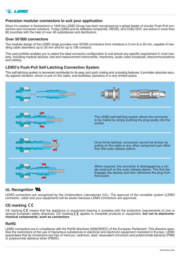
LEMO’s Push-Pull Self-Latching Connection System
The LEMO self-latching system allows the connectorto be mated by simply pushing the plug axially into thesocket.
This self-latching system is renowned worldwide for its easy and quick mating and unmating features. It provides absolute secu-rity against vibration, shock or pull on the cable, and facilitates operation in a very limited space.
®UL RecognitionLEMO connectors are recognized by the Underwriters Laboratories (UL). The approval of the complete system (LEMOconnector, cable and your equipment) will be easier because LEMO connectors are approved.
CE markingCE marking means that the appliance or equipment bearing it complies with the protection requirements of one orseveral European safety directives. CE marking applies to complete products or equipment, but not to electrome-chanical components, such as connectors.
RoHSLEMO connectors are in compliance with the RoHS directives (2002/95/EC) of the European Parliament. This directive spec-ifies the restrictions of the use of hazardous substances in electrical and electronic equipment marketed in Europe. LEMOguarantees that its connectors are free of mercury, cadmium, lead, hexavalent chromium and polybromide biphenyl (PBB)or polybromide diphenyl ether (PBDE).
Once firmly latched, connection cannot be broken bypulling on the cable or any other component part otherthan the outer release sleeve.
When required, the connector is disengaged by a sin-gle axial pull on the outer release sleeve. This first dis-engages the latches and then withdraws the plug fromthe socket.

® ®
www.lemo.com 1
Fixed socket
FHA
FHE
EHA
EHE
FWA
FWE
Straight plugStandard version(IP 50 when mated)
Fixed socket
Fixed plug
Fixed plugStraight plugSealed version(IP 68 when mated)
FHA
FHE
Straight plug
Straight plug
The LEMO Hermaphroditic series provide a rugged high performance patented push-pull hermaphroditic interconnection system. These «genderless» connectors combine LEMO’s well proven push-pull latching technology and the use of our standard high quality optical and electrical contacts.The main features of these series are as follow:– security of a new patented push-pull hermaphroditic self-latching system– 2 shell sizes, SH and MH series– compact unsealed version for general purpose applications– rugged waterproof (IP 68) version for all outdoor applications– a choice of multifibre or electrical contacts configurations– lightweight design with shell in anthracite nickel-plated aluminium alloy– low loss ceramic PC technology in multimode and singlemode– gold plated electrical contacts.Each series consists of plug and socket which will accept cable diameter ranging from 3.6 mm to 10 mm. Initial program isgiving solutions with 2, 4 or 6 fibre optic channel and 6 or 12 electrical contacts.
Part Section Showing Internal Components
5
shelllatch sleeveinner shellspringcirclip
4
3
5
1
2
collet nutinsulatoroptical contactcable adapterbend relief
9
8
10
6
7
16910 3 8742 37128 9 10654
SH-MH Series
Outer shell, collet nut1)
Latch sleeveOther metallic partsSpringInsulatorElectrical contactsO-ring and gaskets
Material (Standard)
Alum. (AA 6262A or AA 6023)Special brassAlum. (AA 6262A or AA 6023)Stainless steelPEEKBrass (male)/Bronze (female)Silicone MQ / MVQ
– 5 –0.5 3 –– 5 –
without treatmentwithout treatment0.5 3 1
without treatment
Surface treat (µm)nickel
Cu Ni Au
Notes: 1) anthracite colour
Materials and Treatments
2
® ®
www.lemo.com
Technical Characteristics
0.18 dB IEC 61300-03-34
0.25 dB IEC 61300-03-34
≥45 dB IEC 61300-03-06
>25 dB IEC 61300-03-06
Method 2
Method 2
CouplerMethod
CouplerMethod
Optical
Average insertion lossfibre 9/125 µm
Average insertion lossfibre 50/125 µm
Return loss fibre 9/125 µm(UPC)
Return loss fibre 9/125 µm(Hand polish)
Characteristic Value Standard Method
Mechanical and Environmental
2000 cycles IEC 60512-5 test 9a-55°C to +125°C1)
10-2000 Hz, 15g IEC 60512-4 test 6d100 g, 6 ms IEC 60512-4 test 6cIP 68 IEC 60529
up to 2 meters depthIP 50 IEC 60529600 N300 N
IEC 60512-8 test 15f800 N400 N
Mating durabilityTemperature rangeVibration resistanceShock resistanceProtection index FHE/FHEWater immersion FHE/FHEProtection index FHA/FHA
plug/plugplug/socketplug/plugplug/socket
Value StandardCharacteristic
Electrical
> 1012 Ω IEC 60512-2 test 3a< 3.6 mΩ IEC 60512-2 test 11f< 10 mΩ IEC 60512-2 test 2f
Insulation resistanceContact resistanceShell resistance
Value StandardCharacteristic
SHseriesAverage
latchingretention MH
series
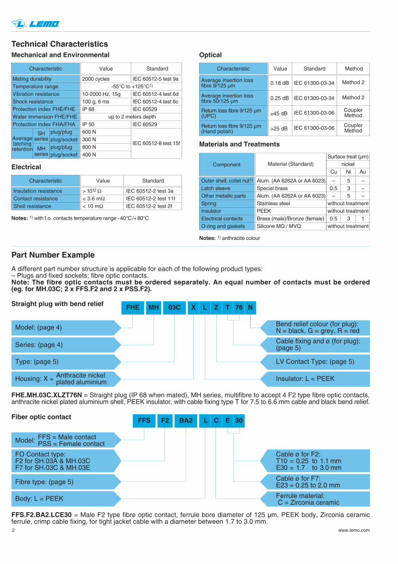
FFS.F2.BA2.LCE30 = Male F2 type fibre optic contact, ferrule bore diameter of 125 µm, PEEK body, Zirconia ceramicferrule, crimp cable fixing, for tight jacket cable with a diameter between 1.7 to 3.0 mm.
Fiber optic contact FFS F2
Fibre type: (page 5)
Body: L = PEEK
BA2
FO Contact type: F2 for SH.03A & MH.03CF7 for SH.03C & MH.03E
L C E 30
FFS = Male contactModel: PSS = Female contact
Ferrule material: C = Zirconia ceramic
Cable ø for F2:T10 = 0.25 to 1.1 mmE30 = 1.7 to 3.0 mm
Cable ø for F7:E23 = 0.25 to 2.0 mm
Part Number Example
A different part number structure is applicable for each of the following product types:– Plugs and fixed sockets; fibre optic contacts.Note: The fibre optic contacts must be ordered separately. An equal number of contacts must be ordered (eg. for MH.03C; 2 x FFS.F2 and 2 x PSS.F2).
FHE.MH.03C.XLZT76N = Straight plug (IP 68 when mated), MH series, multifibre to accept 4 F2 type fibre optic contacts,anthracite nickel plated aluminium shell, PEEK insulator, with cable fixing type T for 7.5 to 6.6 mm cable and black bend relief.
FHE MH
Anthracite nickelHousing: X = plated aluminium
Cable fixing and ø (for plug):(page 5)
Bend relief colour (for plug):N = black, G = grey, R = red
LV Contact Type: (page 5)
03C
Series: (page 4)
Model: (page 4)
X L Z T 76 N
Type: (page 5)
Insulator: L = PEEK
Straight plug with bend relief
Component
Notes: 1) with f.o. contacts temperature range -40°C/+80°C

ø A
S 2~M
~N
~L
Straight plug with cable adapter or collet and nut with bend relief
Reference
Model Series
Dimensions (mm)
A L M N S2
FHA SHFHA MH
21.8 98.4 82.2 46.2 1325.4 109.3 89.1 47.1 15
FHA
S 2 S 1 S 3
~L
ø Aeø B
ME maxi
Fixed plug, nut fixing
Reference
Model Series
Dimensions (mm)
A B e E L M S1 S2 S3
FWA SHFWA MH
28.5 28.5 M22x1 14 55.0 26.5 20.5 14 2534.0 34.0 M25x1 17 64.5 31.5 23.5 17 30
FWA
B + 0.1 0
ø A
+0.
1
0 Dim. (mm)
ø A BSeries
SHMH
22.2 20.625.2 23.6
Panel cut-outs
3
® ®
www.lemo.com
eø B
S 1 S 3
M7 maxi
N
~L
ø A
P
Fixed socket, nut fixing
Reference
Model Series
Dimensions (mm)
A B e M N P S1 S3
EHA SHEHA MH
27 28.5 M22x1 38.8 30.5 19.5 30.5 3.3 20.5 2532 34.0 M25x1 40.8 37.0 24.5 37.0 4.3 23.5 30
EHA
Loptic elect.
B + 0.1 0
ø A
+0.
1
0 Dim. (mm)
ø A BSeries
SHMH
22.2 20.625.2 23.6
Panel cut-outs
Models - Series
4
® ®
www.lemo.com
ø A
S 2~M
~N
~L
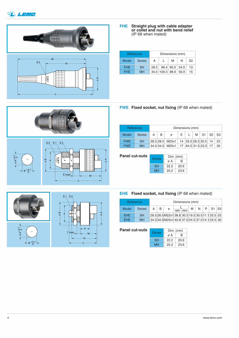
Straight plug with cable adapter or collet and nut with bend relief(IP 68 when mated)
Reference
Model Series
Dimensions (mm)
A L M N S2
FHE SHFHE MH
28.5 98.4 90.0 54.0 1334.0 109.3 98.9 56.9 15
FHE
eø B
S 1 S 3
M
P
7 maxi
N
~L
ø A
Fixed socket, nut fixing (IP 68 when mated)
Reference
Model Series
EHE SHEHE MH
EHE
Dimensions (mm)
A B e M N P S1 S3
28.5 28.5 M22x1 38.8 30.5 19.5 30.5 11.1 20.5 2534.0 34.0 M25x1 40.8 37.0 24.5 37.0 14.1 23.5 30
Loptic elect.
Dim. (mm)ø A B
B + 0.1 0
ø A
+0.
1
0
Series
SHMH
22.2 20.625.2 23.6
Panel cut-outs
S 2 S 1 S 3
~L
ø Aeø B
ME maxi
Fixed socket, nut fixing (IP 68 when mated)
Reference
Model Series
Dimensions (mm)
A B e E L M S1 S2 S3
FWE SHFWE MH
28.5 28.5 M22x1 14 55.0 26.5 20.5 14 2534.0 34.0 M25x1 17 64.5 31.5 23.5 17 30
FWE
B + 0.1 0
ø A
+0.
1
0 Dim. (mm)
ø A BSeries
SHMH
22.2 20.625.2 23.6
Panel cut-outs

5
Note: Other arrangement, optical, electrical or mixed optical-electrical can be made available upon request.WARNING: There is no contact number on the insulator. When wiring one hermaphroditic connector, one should terminate each contact to its mirror imagenumber of the other connector.
125 ●
126 ●
128 ●
9/12550/12562.5/125
ø Core/Cladding Ferrule hole Note(µm) ø (µm)
® ®
www.lemo.com
SH
MHF
2 N
b
F7
Nb
Con
tact
Nb
ø A
(mm
)
Sol
der
Crim
p
Tes
t vol
tage
(kV
rms)
Tes
t vol
tage
(kV
dc)
Rat
ed c
urre
nt (A
)
Contacttype
AWGmax
AWG
Low Voltage contactFO contact
03A
03C
306
2 – – – – – – – –
– 4 – – – – – – –
– – 6 1.3 20 18-20 1.5 2.1 12
03C
03E
312
4 – – – – – – – –
– 6 – – – – – – –
– – 12 1.3 20 18-20 1.0 1.5 8
ø A
ø A
Ref
eren
ce
Plug Socket
Electrical contact
Fibre type
Reference
ACL
Contact type
solder for plugcrimp for plugsolder for socket
Reference
MZ
Contact type
crimp for socketno contact
Referencefor F7 contact
125126128
Referencefor F2 contact
BA2BB2BD2
● First choice alternative ● Special order alternative
4.5 3.65.5 4.66.5 5.67.5 6.6
T46T56T66T76
Cable ømax min
Ref.
SH
5.5 4.66.5 5.67.5 6.68.5 7.69.0 8.6
T56T66T76T86T91
MH
Adapter «T» for fibre optic connectors
5.0 4.16.0 5.17.0 6.18.0 7.1
C52C62C72C82
Cable ømax min
Ref.
6.0 5.17.0 6.18.0 7.19.0 8.110.0 9.1
C62C72C82C92C10
Collet «C» for electrical connectors
Cable diameter
Insert configuration

6
® ®
www.lemo.com
Accessories
Cap (for FHA and FWA plugs)
ø A
L6
sliding loop
BFA
● Body material: Anthracite nickel plated aluminium alloy● Lanyard material: Stainless steel● Crimp ferrule material: Nickel-plated brass + polyolefin● Maximum operating temperature: 125°C● Watertightness: IP50 according to IEC 60529
BFA.SH.100.XAZBFA.MH.100.XAZ
Dim. (mm)A L
21.8 23.525.4 30.0
Part number
Cap (for FHE and FWE plugs)
ø A
L6
sliding loop
BFE
● Body material: Anthracite nickel plated aluminium alloy● Lanyard material: Stainless steel● Crimp ferrule material: Nickel-plated brass + polyolefin● O-ring material: Silicone rubber ● Maximum operating temperature: 125°C● Watertightness: IP68 according to IEC 60529
BFE.SH.100.XASBFE.MH.100.XAS
Dim. (mm)A L
28.5 23.534.0 30.0
Part number
Cap (for FHA and FWA plugs)
N
ø 3
.5
ø A
L6
BHA
● Body material: Anthracite nickel plated aluminium alloy● Lanyard material: Stainless steel● Crimp ferrule material: Nickel-plated brass + polyolefin● Maximum operating temperature: 125°C● Watertightness: IP50 according to IEC 60529
BHA.SH.100.XAZBHA.MH.100.XAZ
Dim. (mm)A L N
21.8 23.5 12025.4 30.0 120
Part number

7
® ®
www.lemo.com
Cap (for FHE and FWE plugs)
ø A
L6
N
ø 3
.5
BHE
● Body material: Anthracite nickel plated aluminium alloy● Lanyard material: Stainless steel● Crimp ferrule material: Nickel-plated brass + polyolefin● O-ring material: Silicone rubber● Maximum operating temperature: 125°C● Watertightness: IP68 according to IEC 60529
BHE.SH.100.XASBHE.MH.100.XAS
Part numberDim. (mm)
A L N
28.5 23.5 12034.0 30.0 120
8
® ®
www.lemo.com
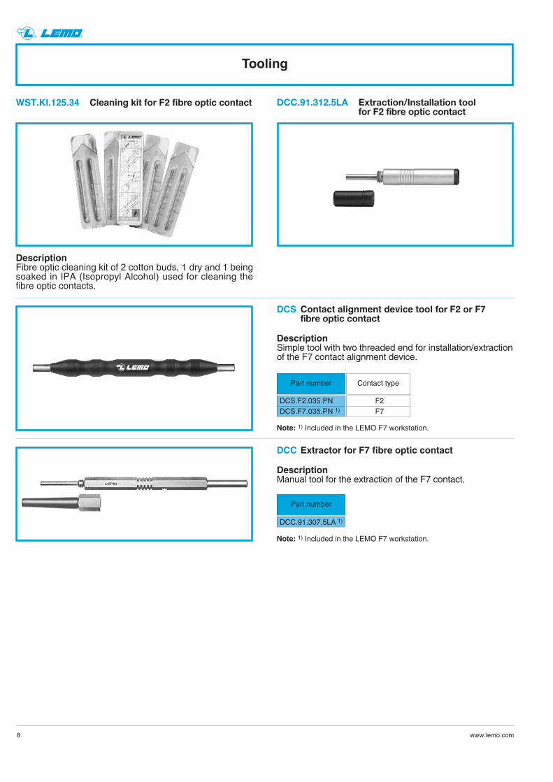
Tooling
DescriptionFibre optic cleaning kit of 2 cotton buds, 1 dry and 1 beingsoaked in IPA (Isopropyl Alcohol) used for cleaning thefibre optic contacts.
DCC.91.312.5LA Extraction/Installation tool for F2 fibre optic contact
WST.KI.125.34 Cleaning kit for F2 fibre optic contact
Contact alignment device tool for F2 or F7fibre optic contact
Part number
DCS.F2.035.PNDCS.F7.035.PN 1)
DCS
Contact type
F2F7
Note: 1) Included in the LEMO F7 workstation.
Extractor for F7 fibre optic contact
Part number
DCC.91.307.5LA 1)
DCC
DescriptionManual tool for the extraction of the F7 contact.
Note: 1) Included in the LEMO F7 workstation.
DescriptionSimple tool with two threaded end for installation/extractionof the F7 contact alignment device.

® ®
www.lemo.com
PLEASE READ AND FOLLOW ALL INSTUCTIONS CAREFULLY AND CONSULT ALL RELEVENT NATIONAL ANDINTERNATIONAL SAFETY REGULATIONS FOR YOUR APPLICATION.IMPROPER HANDLING, CABLE ASSEMBLY, OR WRONG USE OF CONNECTORS CAN RESULT IN HAZARDOUSSITUATIONS.
1. SHOCK AND FIRE HAZARDIncorrect wiring, the use of damaged components, presence of foreign objects (such as metal debris), and / or residue (such as cleaning fluids), can result in short circuits, overheating, and / or risk of electric shock.Mated components should never be disconnected while live as this may result in an exposed electric arc and local overheating, resulting in possible damage to components.
2. HANDLINGConnectors and their components should be visually inspected for damage prior to installation and assembly. Suspect components should be rejected or returned to the factory for verification.Connector assembly and installation should only be carried out by properly trained personnel. Proper tools must be usedduring installation and / or assembly in order to obtain safe and reliable performance.
3. USEConnectors with exposed contacts should never be live (or on the current supply side of a circuit). Under general conditions voltages above 30 VAC and 42 VDC are considered hazardous and proper measures should be taken to eliminate all risk of transmission of such voltages to any exposed metal part of the connector.
4. TEST AND OPERATING VOLTAGESThe maximum admissible operating voltage depends upon the national or international standards in force for the application in question. Air and creepage distances impact the operating voltage; reference values are indicated in the catalog however these may be influenced by PC board design and / or wiring harnesses.The test voltage indicated in the catalog is 75% of the mean breakdown voltage; the test is applied at 500 V/s and the test duration is 1 minute.
5. CE MARKINGCE Marking is applied to a complete product or device, and implies that the device complies with one or several Europeansafety directives.CE Marking can not be applied to electromechanical components such as connectors.
6. PRODUCT IMPROVEMENTSThe LEMO Group reserves the right to modify and improve to our products or specifications without providing prior notification.
Product safety notice

LEMO HEADQUARTERS
SWITZERLANDLEMO SA Chemin des Champs-Courbes 28 - P.O. Box 194 - CH-1024 EcublensTel. (+41 21) 695 16 00 - Fax (+41 21) 695 16 01 - e-mail: [email protected]
LEMO SUBSIDIARIES
AUSTRIALEMO Elektronik GesmbHLemböckgasse 49/E6-31230 WienTel: (+43 1) 914 23 20 0Fax:(+43 1) 914 23 20 [email protected]
CHINALEMO Trading (Shanghai) Co., Ltd. LEMO Electronics (Shanghai) Co.,Ltd. 5th Floor, Block 6, City of ELITE,1000 Jinhai Road, PudongShanghai, China 201206Tel: (+86 21) 5899 7721Fax: (+86 21) 5899 [email protected]
DENMARKLEMO Denmark A/SGammel Mosevej 462820 GentofteTel: (+45) 45 20 44 00Fax: (+45) 45 20 44 [email protected]
FRANCELEMO France Sàrl165, avenue Jean Jaurès94700 Maisons AlfortTel: (+33 1) 45 17 27 90Fax: (+33 1) 45 17 27 [email protected]
GERMANYLEMO Elektronik GmbHHanns-Schwindt-Str. 681829 München Tel: (+49 89) 42 77 03Fax: (+49 89) 420 21 [email protected]
HONG KONGLEMO Hong Kong Ltd.Room 33. 7th FloorHITEC, 1 Trademart DriveKowloon Bay - Hong KongTel: (+852) 2174 0468Fax: (+852) 2174 [email protected]
HUNGARYREDEL Elektronika KftVágóhíd u. 261201 Budapest XX.Tel: (+36 1) 421 47 10Fax: (+36 1) 421 47 [email protected]
ITALYLEMO Italia srlViale Lunigiana 2520125 MilanoTel: (+39 02) 66 71 10 46Fax: (+39 02) 66 71 10 [email protected]
JAPANLEMO JAPAN Ltd4-10-3, Takaido Higashi, Suginami-ku, Tokyo, 168-0072Tel: (+81 3) 53 44 39 33Fax: (+81 3) 53 44 39 [email protected]
NETHERLANDS / BELGIUMLEMO Connectors BeneluxDe Trompet 21081967 DC HeemskerkTel. (+31) 251 25 78 20Fax (+31) 251 25 78 [email protected]
NORWAY / ICELANDLEMO Norway A/SStanseveien 6B0975 OsloTel: (+47) 22 91 70 40Fax: (+47) 22 91 70 [email protected]
SPAIN / PORTUGALIBERLEMO S.A.Brasil, 45, 08402 GranollersBarcelonaTel: (+34 93) 860 44 20Fax: (+34 93) 879 10 [email protected]
Madrid OfficeAntonio López, 96, 28019 MadridTel: (+34 91) 469 99 19Fax: (+34 91) 469 99 59
SWEDEN / FINLANDLEMO Nordic ABMariehällsvägen 39A 168 65 BrommaTel: (+46 8) 635 60 60Fax: (+46 8) 635 60 [email protected]
SWITZERLANDLEMO Verkauf AGGrundstrasse 22 B6343 RotkreuzTel: (+41 41) 790 49 40Fax: (+41 41) 790 49 [email protected]
UNITED KINGDOMLEMO UK LtdUnit 15 & 16Hazelwood Trading EstateWorthing, West Sussex, BN14 8NPTel: (+44 1903) 23 45 43Fax: (+44 1903) 20 62 [email protected]
USALEMO USA IncP.O. Box 2408Rohnert Park, CA 94927-2408Tel: (+1 707) 578 88 11(+1 800) 444 53 66Fax:(+1 707) 578 08 [email protected]
CA
T.M
H.L
EN
.P0
90
8
LEMO DISTRIBUTORS
AUSTRALIA, BRAZIL, CANADA, CZECH REPUBLIC, GREECE, INDIA, ISRAEL,MALAYSIA, NEW ZEALAND, PHILIPPINES, POLAND, RUSSIA, SINGAPORE, SOUTH AFRICA, SOUTH KOREA, TAIWAN, THAILAND, TURKEY, UKRAINE
www.lemo.com