hewlett-packard company hp networking 3800 switch series...hewlett-packard company makes no warranty...
TRANSCRIPT

Hewlett-Packard CompanyHP Networking 3800 Switch SeriesHardware Versions:
Switches: (3800-24G-PoE+(J9574A) [2]; 3800-24G-2SFP+ Switch (J9575A) [3]; 3800[4]; 3800-24G-2XG Switch (J9585A) [5]; 380024G-PoE+-2XG Switch (J9587A) [7]; 380024SFP-2SFP+ Switch (J9584A) [9]); Power Supplies: (J9580A [1,2,7,8] and J9581 [3,4,5,6,9]) with Tamper Evident Se
Firmware Version: KA.15.10.0015
FIPS 140-2 Non-Proprietary Security Policy
FIPS Security Level: 2 Document Version: 1.3
Prepared for:
Hewlett-Packard Company8000 Foothills BlvdRosevillle, CA 95747
United States of America
Phone: +1 (800) 334http://www.hp.com
Packard Company HP Networking 3800 Switch Series
PoE+-2SFP+ Switch (J9573A) [1]; 3800-48G2SFP+ Switch (J9575A) [3]; 3800-48G-4SFP+ Switch (J9576A)
2XG Switch (J9585A) [5]; 3800-48G-4XG Switch (J9586A) [6]; 2XG Switch (J9587A) [7]; 3800-48G-PoE+-4XG Switch (J9588A) [8]; 3800
2SFP+ Switch (J9584A) [9]); Power Supplies: (J9580A [1,2,7,8] and J9581 [3,4,5,6,9]) with Tamper Evident Seal Kit: J9740A
Firmware Version: KA.15.10.0015
Proprietary Security Policy
Prepared for: Prepared by:
Packard Company Corsec Security, Inc.
8000 Foothills Blvd Rosevillle, CA 95747
13135 Lee Jackson Memorial Hwy., Suite 220Fairfax, VA 2203
of America United States
334-5144
Phone: +1 (703) 267http://www.hp.com http://www.corsec.com
48G-PoE+-4SPF+ Switch 4SFP+ Switch (J9576A)
ch (J9586A) [6]; 3800-4XG Switch (J9588A) [8]; 3800-
2SFP+ Switch (J9584A) [9]); Power Supplies: (J9580A [1,2,7,8] and J9581
Prepared by:
Corsec Security, Inc.
Memorial Hwy., Suite 220 Fairfax, VA 22033
of America
(703) 267-6050 http://www.corsec.com

Security Policy, Version 1.3 December 16, 2013
HP Networking 3800 Switch Series Page 2 of 43
© Copyright 2013 Hewlett-Packard Development Company, L.P. This document may be freely reproduced and distributed whole and intact including this copyright notice.
Products indentified herein contain confidential commercial computer software. Valid license required.
Disclaimer The information contained in this document is subje ct to change without notice. HEWLETT-PACKARD COMPANY MAKES NO WARRANTY OF ANY KIND WITH REGARD TO THIS MATERIAL, INCLUDING, BUT NOT LIMITED TO, THE I MPLIED WARRANTIES OF MERCHANTABILITY AND FITNESS FOR A PARTICULAR PURPOSE. Hewlett-Packard shall not be liable for errors cont ained herein or for incidental or consequential damages in connection w ith the furnishing, performance, or use of this material. The only warranties for HP products and services ar e set forth in the express warranty statements accompanying such produ cts and services. Nothing herein should be construed as constituting an additional warranty. HP shall not be liable for technical or editorial errors or omissions contained herein. Hewlett-Packard assumes no responsibility for the u se or reliability of its software on equipment that is not furnished by Hewlett-Packard.

Security Policy, Version 1.3 December 16, 2013
HP Networking 3800 Switch Series Page 3 of 43
© Copyright 2013 Hewlett-Packard Development Company, L.P. This document may be freely reproduced and distributed whole and intact including this copyright notice.
Products indentified herein contain confidential commercial computer software. Valid license required.
Table of Contents 1 INTRODUCTION ................................................................................................................... 5
1.1 PURPOSE ................................................................................................................................................................ 5
1.2 REFERENCES .......................................................................................................................................................... 5
1.3 DOCUMENT ORGANIZATION ............................................................................................................................ 5
2 HP NETWORKING 3800 SWITCH SERIES ......................................................................... 6
2.1 OVERVIEW ............................................................................................................................................................. 6
2.2 MODULE SPECIFICATION ..................................................................................................................................... 7
2.3 MODULE INTERFACES .......................................................................................................................................... 9
2.4 ROLES AND SERVICES ......................................................................................................................................... 18
2.4.1 Crypto Officer Role ............................................................................................................................................. 18
2.4.2 User Role ................................................................................................................................................................ 20
2.4.3 Authentication ....................................................................................................................................................... 20
2.5 PHYSICAL SECURITY ........................................................................................................................................... 21
2.6 OPERATIONAL ENVIRONMENT ......................................................................................................................... 21
2.7 CRYPTOGRAPHIC KEY MANAGEMENT ............................................................................................................ 21
2.8 SELF-TESTS .......................................................................................................................................................... 28
2.8.1 Power-Up Self-Tests ............................................................................................................................................ 28
2.8.2 Conditional Self-Tests ......................................................................................................................................... 28
2.9 MITIGATION OF OTHER ATTACKS .................................................................................................................. 29
3 SECURE OPERATION ......................................................................................................... 30
3.1 INITIAL APPLIANCE SETUP ................................................................................................................................. 30
3.1.1 Tamper-Evidence Label Placement ............................................................................................................... 30
3.2 INITIALIZATION OF FIPS MODE ....................................................................................................................... 34
3.2.1 Pre-Initialization ................................................................................................................................................... 34
3.2.2 Initialization and Configuration ....................................................................................................................... 35
3.2.3 Zeroization ............................................................................................................................................................ 38
3.3 SECURE MANAGEMENT ..................................................................................................................................... 38
3.4 USER GUIDANCE ................................................................................................................................................ 39
3.5 BOOTROM GUIDANCE .................................................................................................................................... 39
3.6 NON-APPROVED MODE OF OPERATION ....................................................................................................... 39
3.6.1 Transitioning to the Non-Approved Mode................................................................................................... 39
3.6.2 Non-Approved Security Services ..................................................................................................................... 40
3.6.3 Non-Approved Security Functions .................................................................................................................. 40
3.6.4 Roles ........................................................................................................................................................................ 40
4 ACRONYMS .......................................................................................................................... 41
Table of Figures FIGURE 1 – HP NETWORKING 3800 SWITCH SERIES MODULES ........................................................................................ 6
FIGURE 2 – HP NETWORKING 3800 SWITCH SERIES CRYPTOGRAPHIC BOUNDARY ..................................................... 8
FIGURE 3 – HP 3800-24G-POE+-2SFP+ SWITCH .............................................................................................................. 9
FIGURE 4 – HP 3800-48G-POE+-4SFP+ SWITCH ........................................................................................................... 10
FIGURE 5 – HP 3800-24G-2SFP+ SWITCH ....................................................................................................................... 11
FIGURE 6 – HP 3800-48G-4SFP+ SWITCH ....................................................................................................................... 12
FIGURE 7 – HP 3800-24G-2XG SWITCH .......................................................................................................................... 13
FIGURE 8 – HP 3800-48G-4XG SWITCH .......................................................................................................................... 14
FIGURE 9 – HP 3800-24G-POE+-2XG SWITCH .............................................................................................................. 15
FIGURE 10 – HP 3800-48G-POE+-4XG SWITCH ............................................................................................................ 16

Security Policy, Version 1.3 December 16, 2013
HP Networking 3800 Switch Series Page 4 of 43
© Copyright 2013 Hewlett-Packard Development Company, L.P. This document may be freely reproduced and distributed whole and intact including this copyright notice.
Products indentified herein contain confidential commercial computer software. Valid license required.
FIGURE 11 – HP 3800-24SFP-2SFP+ SWITCH .................................................................................................................. 17
FIGURE 12 – HP NETWORKING 3800 SWITCH SERIES REAR VIEW ................................................................................ 17
FIGURE 13 – LEFT-HAND SIDE VENT OPENINGS TAMPER-EVIDENCE LABEL PLACEMENT (STEP 1) ............................ 31
FIGURE 14 – LEFT-HAND SIDE VENT OPENINGS TAMPER-EVIDENCE LABEL PLACEMENT (STEP 2) ............................ 31
FIGURE 15 – RIGHT-HAND SIDE TAMPER-EVIDENCE LABEL PLACEMENT ...................................................................... 32
FIGURE 16 – OOBM AND TOP PANEL TAMPER-EVIDENCE LABEL PLACEMENT (24-PORT SWITCH) ........................ 32
FIGURE 17 – OOBM AND TOP PANEL TAMPER-EVIDENCE LABEL PLACEMENT (48-PORT SWITCH) ........................ 32
FIGURE 18 – REAR OF SWITCH TAMPER-EVIDENCE LABEL PLACEMENT ......................................................................... 33
FIGURE 19 – REAR VENTILATION HOLES TAMPER-EVIDENCE LABEL PLACEMENT ........................................................ 33
FIGURE 20 – POWER SUPPLY TAMPER-EVIDENCE LABEL PLACEMENT ............................................................................. 33
List of Tables TABLE 1 – SECURITY LEVEL PER FIPS 140-2 SECTION ......................................................................................................... 7
TABLE 2 – MAPPING OF FIPS 140-2 LOGICAL INTERFACES TO THE HP 3800-24G-POE+-2SFP+ SWITCH ............... 9
TABLE 3 – MAPPING OF FIPS 140-2 LOGICAL INTERFACES TO THE HP 3800-48G-POE+-4SFP+ SWITCH ............ 10
TABLE 4 – MAPPING OF FIPS 140-2 LOGICAL INTERFACES TO THE HP 3800-24G-2SFP+ SWITCH ........................ 11
TABLE 5 – MAPPING OF FIPS 140-2 LOGICAL INTERFACES TO THE HP 3800-48G-4SFP+ SWITCH ........................ 12
TABLE 6 – MAPPING OF FIPS 140-2 LOGICAL INTERFACES TO THE HP 3800-24G-2XG SWITCH ........................... 13
TABLE 7 – MAPPING OF FIPS 140-2 LOGICAL INTERFACES TO THE HP 3800-48G-4XG SWITCH ........................... 14
TABLE 8 – MAPPING OF FIPS 140-2 LOGICAL INTERFACES TO THE HP 3800-24G-POE+-2XG SWITCH ............... 15
TABLE 9 – MAPPING OF FIPS 140-2 LOGICAL INTERFACES TO THE HP 3800-48G-POE+-4XG SWITCH ............... 16
TABLE 10 – MAPPING OF FIPS 140-2 LOGICAL INTERFACES TO THE HP 3800-24SFP-2SFP+ SWITCH ................... 17
TABLE 11 – CRYPTO OFFICER SERVICES ............................................................................................................................. 18
TABLE 12 – USER SERVICES ................................................................................................................................................... 20
TABLE 13 – FIPS-APPROVED ALGORITHM IMPLEMENTATIONS ........................................................................................ 21
TABLE 14 – LIST OF CRYPTOGRAPHIC KEYS, CRYPTOGRAPHIC KEY COMPONENTS, AND CSPS .............................. 23
TABLE 15 – ACRONYMS ........................................................................................................................................................ 41

Security Policy, Version 1.3 December 16, 2013
HP Networking 3800 Switch Series Page 5 of 43
© Copyright 2013 Hewlett-Packard Development Company, L.P. This document may be freely reproduced and distributed whole and intact including this copyright notice.
Products indentified herein contain confidential commercial computer software. Valid license required.
1 Introduction
1.1 Purpose This is a non-proprietary Cryptographic Module Security Policy for the HP Networking 3800 Switch Series from Hewlett-Packard Company (also referred to as HP). This Security Policy describes how the HP Networking 3800 Switch Series meets the security requirements of Federal Information Processing Standards (FIPS) Publication 140-2, which details the U.S. and Canadian Government requirements for cryptographic modules. More information about the FIPS 140-2 standard and validation program is available on the National Institute of Standards and Technology (NIST) and the Communications Security Establishment Canada (CSEC) Cryptographic Module Validation Program (CMVP) website at http://csrc.nist.gov/groups/STM/cmvp. This document also describes how to operate the module in a secure FIPS-Approved mode of operation. This policy was prepared as part of the Level 2 FIPS 140-2 validation of the module. The HP Networking 3800 Switch Series is referred to in this document as the 3800 Switch Series modules, the cryptographic modules, or the modules.
1.2 References This document deals only with operations and capabilities of the module in the technical terms of a FIPS 140-2 cryptographic module security policy. More information is available on the module from the following sources:
• The HP website (http://www.hp.com) contains information on the full line of products from HP. • The CMVP website (http://csrc.nist.gov/groups/STM/cmvp/documents/140-1/140val-all.htm)
contains contact information for individuals to answer technical or sales-related questions for the module.
1.3 Document Organization The Security Policy document is one document in a FIPS 140-2 Submission Package. In addition to this document, the Submission Package contains:
• Vendor Evidence document • Finite State Model document • Other supporting documentation as additional references
This Security Policy and the other validation submission documentation were produced by Corsec Security, Inc. under contract to HP. With the exception of this Non-Proprietary Security Policy, the FIPS 140-2 Submission Package is proprietary to HP and is releasable only under appropriate non-disclosure agreements. For access to these documents, please contact HP.

Security Policy, Version 1.3
HP Networking 3800 Switch Series
© Copyright 201This document may be freely reproduced and distributed whole and intact including this copyright notice.
Products indentified herein contain confidential commercial computer software. Valid license required.
2
2.1 Overview The HP Networking 3800 Switch SeriesLayer 2/3 enterprise-class access layer switchesHP ProVision ASIC1, delivers unmatched performance and scalability to meedemanding enterprise networksconnectivity for high-performance links to the network aggregation and corethroughput and network link redundancy The HP Networking 3800 Switch Seriesproviding advanced Layer 2/3 protocols and features uniquely suited for largeThe switches offer a choice of twentyand non-PoE connectivity optionsconverged devices and enable granular power controlavailable with either Small Formflexibility in deploying high-speed connectivity Figure 1 shows all nine of the validated
Figure 1
1 ASIC – Application-Specific Integrated Circuit2 Gb – Gigabit 3 GbE – Gigabit Ethernet (10/100/1000)
© Copyright 2013 Hewlett-Packard Development Company, L.P. This document may be freely reproduced and distributed whole and intact including this copyright notice.
Products indentified herein contain confidential commercial computer software. Valid license required.
HP Networking 3800 Switch Series
HP Networking 3800 Switch Series cryptographic modules are a family of nextclass access layer switches. The 3800 Switch Series, which is designed with a custom , delivers unmatched performance and scalability to meet the needs of the most
demanding enterprise networks. The HP Networking 3800 Switch Series modules integrate 10 Gbperformance links to the network aggregation and core; allowing for increased
throughput and network link redundancy.
Networking 3800 Switch Series modules are available in nine different configurationsproviding advanced Layer 2/3 protocols and features uniquely suited for large-scale enterprise solutionsThe switches offer a choice of twenty-four or forty-eight GbE3 ports with Power over Ethernet+ (PoE+)
PoE connectivity options. The GbE copper ports with PoE+ capability support advanced converged devices and enable granular power control. In addition, the 3800 Switch Seriesavailable with either Small Form-factor Pluggable+ (SFP+) or 10GBase-T 10G uplinks, offering ultimate
speed connectivity.
shows all nine of the validated HP Networking 3800 Switch Series cryptographic modules
1 – HP Networking 3800 Switch Series Modules
Specific Integrated Circuit
Gigabit Ethernet (10/100/1000)
December 16, 2013
Page 6 of 43
This document may be freely reproduced and distributed whole and intact including this copyright notice.
Products indentified herein contain confidential commercial computer software. Valid license required.
Networking 3800 Switch
cryptographic modules are a family of next-generation gigabit , which is designed with a custom
the needs of the most modules integrate 10 Gb2
; allowing for increased
modules are available in nine different configurations, each scale enterprise solutions.
ports with Power over Ethernet+ (PoE+) The GbE copper ports with PoE+ capability support advanced
3800 Switch Series modules are 0G uplinks, offering ultimate
cryptographic modules.
Modules

Security Policy, Version 1.3 December 16, 2013
HP Networking 3800 Switch Series Page 7 of 43
© Copyright 2013 Hewlett-Packard Development Company, L.P. This document may be freely reproduced and distributed whole and intact including this copyright notice.
Products indentified herein contain confidential commercial computer software. Valid license required.
Listed below are the nine configurations of the HP Networking 3800 Switch Series, which have been evaluated for Level 2 FIPS 140-2 security requirements, and are covered in this Security Policy.
• 3800-24G-PoE+-2SFP+ Switch (J9573A) • 3800-48G-PoE+-4SPF+ Switch (J9574A) • 3800-24G-2SFP+ Switch (J9575A) • 3800-48G-4SFP+ Switch (J9576A) • 3800-24G-2XG Switch (J9585A) • 3800-48G-4XG Switch (J9586A) • 3800-24G-PoE+-2XG Switch (J9587A) • 3800-48G-PoE+-4XG Switch (J9588A) • 3800-24SFP-2SFP+ Switch (J9584A)
The cryptographic modules being evaluated for FIPS 140-2 security requirements are the 3800 Switch Series. Table 1 lists the FIPS 140-2 Section levels at which the 3800 Switch Series are validated.
Table 1 – Security Level Per FIPS 140-2 Section
Section Section Title Level
1 Cryptographic Module Specification 2
2 Cryptographic Module Ports and Interfaces 2
3 Roles, Services, and Authentication 2
4 Finite State Model 2
5 Physical Security 2
6 Operational Environment N/A
7 Cryptographic Key Management 2
8 EMI/EMC4 2
9 Self-tests 2
10 Design Assurance 2
11 Mitigation of Other Attacks N/A
2.2 Module Specification The HP Networking 3800 Switch Series cryptographic modules are hardware modules with multi-chip standalone embodiments. The overall security level of the switches is Level 2. The physical cryptographic boundary of the 3800 Switch Series is defined by the hard, metal chassis, which surrounds all of the hardware and firmware components. The 3800 Switch Series modules are shipped with a Freescale PowerPC P2020E CPU5 @ 1200 MHz, 4 GB6 of Flash storage, and 2 GB DDR73 RAM8. The HP Networking 3800 Switch Series modules are capable of operating in a non-Approved mode of operation. This mode of operation contains non-Approved services and cryptographic algorithm
4 EMI/EMC – Electromagnetic Interference / Electromagnetic Compatibility 5 CPU – Central Processing Unit 6 GB – Gigabytes 7 DDR – Double Data Rate 8 RAM – Random Access Memory

Security Policy, Version 1.3 December 16, 2013
HP Networking 3800 Switch Series Page 8 of 43
© Copyright 2013 Hewlett-Packard Development Company, L.P. This document may be freely reproduced and distributed whole and intact including this copyright notice.
Products indentified herein contain confidential commercial computer software. Valid license required.
implementations. Refer to section 3.6 of this Security Policy for more information on the non-Approved mode of operation. The block diagram shown in Figure 2 shows all major cryptographic components of all nine cryptographic modules. The cryptographic boundary of the 3800 Switch Series modules is indicated using a red, dotted line. Please note that there are excluded components, which lie within the cryptographic boundary. Each excluded component, even if malfunctioning or misused, is not able to leak any plaintext data, CSPs, or other valuable information. Excluded components include network chips, fabric chips, and the PSU Slot Cover. All components of the cryptographic modules are diagramed in Figure 2.
Figure 2 – HP Networking 3800 Switch Series Cryptographic Boundary9
9 RTC – Real Time Clock; ROM – Read Only Memory; DIMM – Dual In-line Memory Module; SDHC – Secure Digital High Capacity; FPGA – Field Programmable Gate Array; LED – Light Emitting Diode; PSU – Power Supply Unit; RJ – Registered Jack

Security Policy, Version 1.3
HP Networking 3800 Switch Series
© Copyright 201This document may be freely reproduced and distributed whole and intact including this copyright notice.
Products indentified herein contain confidential commercial computer software. Valid license required.
2.3 Module InterfacesThe HP Networking 3800 Switchconfigurations. Each of the module
• Data Input • Data Output • Control Input • Status Output • Power
The RJ-45 OOBM10 port, the switch stacking slot, and the USBare operating in their FIPS-Approved configurationwhen the modules are operating listed in the tables below. For more information Section 3 (Secure Operation). Figure 3 shows the front ports and interfaces of the HP 3and additional LEDs are located at the rear of mod
Figure
Table 2 maps the FIPS 140-2 logical interfaces to the physical ports and interfaces of the HP 3800PoE+-2SFP+ Switch.
Table 2 – Mapping of FIPS 140
Physical Interface
(24) RJ-45 GbE PoE+ Ports
(2) 1000/10000 SFP+ Ports
(1) RJ-45 Serial Console Port
(74) LEDs
(1) HP X312 1000W Power Supply
10 OOBM – Out-Of-Band Management11 USB – Universal Serial Bus
© Copyright 2013 Hewlett-Packard Development Company, L.P. This document may be freely reproduced and distributed whole and intact including this copyright notice.
Products indentified herein contain confidential commercial computer software. Valid license required.
Module Interfaces HP Networking 3800 Switch Series cryptographic modules each provide
Each of the module’s interfaces provides the following FIPS 140-2 logical interfaces:
port, the switch stacking slot, and the USB11 port will be disabled when the moduleApproved configuration. The “Clear” and “Reset” buttons will be disabled
operating in their FIPS-Approved configuration. As such, these interfaces are not For more information on disabling these ports and interfaces
shows the front ports and interfaces of the HP 3800-24G-PoE+-2SFP+ Switchand additional LEDs are located at the rear of module (See Figure 12).
Figure 3 – HP 3800-24G-PoE+-2SFP+ Switch
2 logical interfaces to the physical ports and interfaces of the HP 3800
Mapping of FIPS 140-2 Logical Interfaces to the HP 3800-24G-PoE+
Physical Interface Data Input
Data Output
Control Input
Status Output
45 GbE PoE+ Ports � � �
(2) 1000/10000 SFP+ Ports � � �
Port � � �
Power Supply
Band Management
December 16, 2013
Page 9 of 43
This document may be freely reproduced and distributed whole and intact including this copyright notice.
Products indentified herein contain confidential commercial computer software. Valid license required.
cryptographic modules each provide different interface 2 logical interfaces:
port will be disabled when the modules The “Clear” and “Reset” buttons will be disabled
hese interfaces are not and interfaces, please refer to
2SFP+ Switch. The power supply
2 logical interfaces to the physical ports and interfaces of the HP 3800-24G-
PoE+-2SFP+ Switch
Status Output
Power
� �
�
�
�
�

Security Policy, Version 1.3
HP Networking 3800 Switch Series
© Copyright 201This document may be freely reproduced and distributed whole and intact including this copyright notice.
Products indentified herein contain confidential commercial computer software. Valid license required.
Figure 4 shows the front ports and interfaces of the HP 3800and additional LEDs are located at the rear of module (
Figure
Table 3 maps the FIPS 140-2 logical interfaces to the physical ports and interfaces of the HP 3800PoE+-4SFP+ Switch.
Table 3 – Mapping of FIPS 140
Physical Interface
(48) RJ-45 GbE PoE+ Ports
(4) 1000/10000 SFP+ Ports
(1) RJ-45 Serial Console Port
(120) LEDs
(1) HP X312 1000W Power Supply
© Copyright 2013 Hewlett-Packard Development Company, L.P. This document may be freely reproduced and distributed whole and intact including this copyright notice.
Products indentified herein contain confidential commercial computer software. Valid license required.
shows the front ports and interfaces of the HP 3800-48G-PoE+-4SFP+ Switchand additional LEDs are located at the rear of module (See Figure 12).
Figure 4 – HP 3800-48G-PoE+-4SFP+ Switch
2 logical interfaces to the physical ports and interfaces of the HP 3800
Mapping of FIPS 140-2 Logical Interfaces to the HP 3800-48G-PoE+
Physical Interface Data Input
Data Output
Control Input
Status Output
45 GbE PoE+ Ports � � �
(4) 1000/10000 SFP+ Ports � � �
45 Serial Console Port � � �
1000W Power Supply
December 16, 2013
Page 10 of 43
This document may be freely reproduced and distributed whole and intact including this copyright notice.
Products indentified herein contain confidential commercial computer software. Valid license required.
4SFP+ Switch. The power supply
2 logical interfaces to the physical ports and interfaces of the HP 3800-48G-
PoE+-4SFP+ Switch
Status Output
Power
� �
�
�
�
�

Security Policy, Version 1.3
HP Networking 3800 Switch Series
© Copyright 201This document may be freely reproduced and distributed whole and intact including this copyright notice.
Products indentified herein contain confidential commercial computer software. Valid license required.
Figure 5 shows the front ports and interfaces of theadditional LEDs are located at the rear of module (
Table 4 maps the FIPS 140-2 logical interfaces to the physical ports and interfaces of the HP 38002SFP+ Switch.
Table 4 – Mapping of FIPS 140
Physical Interface
(24) RJ-45 GbE Ports
(2) 1000/10000 SFP+ Ports
(1) RJ-45 Serial Console Port
(74) LEDs
(1) HP X311 400W Power Supply
© Copyright 2013 Hewlett-Packard Development Company, L.P. This document may be freely reproduced and distributed whole and intact including this copyright notice.
Products indentified herein contain confidential commercial computer software. Valid license required.
shows the front ports and interfaces of the HP 3800-24G-2SFP+ Switch. additional LEDs are located at the rear of module (See Figure 12).
Figure 5 – HP 3800-24G-2SFP+ Switch
2 logical interfaces to the physical ports and interfaces of the HP 3800
Mapping of FIPS 140-2 Logical Interfaces to the HP 3800-24G
Physical Interface Data Input
Data Output
Control Input
Status Output
� � �
(2) 1000/10000 SFP+ Ports � � �
45 Serial Console Port � � �
(1) HP X311 400W Power Supply
December 16, 2013
Page 11 of 43
This document may be freely reproduced and distributed whole and intact including this copyright notice.
Products indentified herein contain confidential commercial computer software. Valid license required.
. The power supply and
2 logical interfaces to the physical ports and interfaces of the HP 3800-24G-
24G-2SFP+ Switch
Status Output
Power
�
�
�
�
�

Security Policy, Version 1.3
HP Networking 3800 Switch Series
© Copyright 201This document may be freely reproduced and distributed whole and intact including this copyright notice.
Products indentified herein contain confidential commercial computer software. Valid license required.
Figure 6 shows the front ports and interfaces of theadditional LEDs are located at the rear of module (
Table 5 maps the FIPS 140-2 logical interfaces to the physical ports and interfaces of the HP 38004SFP+ Switch.
Table 5 – Mapping of FIPS 140
Physical Interface
(48) RJ-45 GbE Ports
(4) 1000/10000 SFP+ Ports
(1) RJ-45 Serial Console Port
(120) LEDs
(1) HP X311 400W Power Supply
© Copyright 2013 Hewlett-Packard Development Company, L.P. This document may be freely reproduced and distributed whole and intact including this copyright notice.
Products indentified herein contain confidential commercial computer software. Valid license required.
shows the front ports and interfaces of the HP 3800-48G-4SFP+ Switch. additional LEDs are located at the rear of module (See Figure 12).
Figure 6 – HP 3800-48G-4SFP+ Switch
2 logical interfaces to the physical ports and interfaces of the HP 3800
Mapping of FIPS 140-2 Logical Interfaces to the HP 3800-48G
Physical Interface Data Input
Data Output
Control Input
Status Output
� � �
(4) 1000/10000 SFP+ Ports � � �
45 Serial Console Port � � �
(1) HP X311 400W Power Supply
December 16, 2013
Page 12 of 43
This document may be freely reproduced and distributed whole and intact including this copyright notice.
Products indentified herein contain confidential commercial computer software. Valid license required.
. The power supply and
2 logical interfaces to the physical ports and interfaces of the HP 3800-48G-
48G-4SFP+ Switch
Status Output
Power
�
�
�
�
�
Security Policy, Version 1.3
HP Networking 3800 Switch Series
© Copyright 201This document may be freely reproduced and distributed whole and intact including this copyright notice.
Products indentified herein contain confidential commercial computer software. Valid license required.
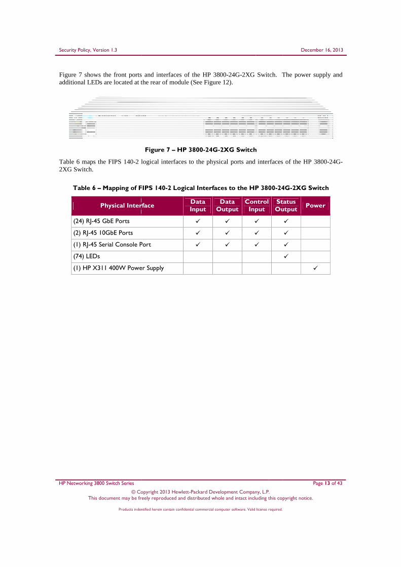
Figure 7 shows the front ports and interfaces of tadditional LEDs are located at the rear of module (
Table 6 maps the FIPS 140-2 logical interfaces to the physical ports and interfaces of the HP 38002XG Switch.
Table 6 – Mapping of FIPS 140
Physical Interface
(24) RJ-45 GbE Ports
(2) RJ-45 10GbE Ports
(1) RJ-45 Serial Console Port
(74) LEDs
(1) HP X311 400W Power Supply
© Copyright 2013 Hewlett-Packard Development Company, L.P. This document may be freely reproduced and distributed whole and intact including this copyright notice.
Products indentified herein contain confidential commercial computer software. Valid license required.
shows the front ports and interfaces of the HP 3800-24G-2XG Switch. The padditional LEDs are located at the rear of module (See Figure 12).
Figure 7 – HP 3800-24G-2XG Switch
2 logical interfaces to the physical ports and interfaces of the HP 3800
Mapping of FIPS 140-2 Logical Interfaces to the HP 3800-24G
Physical Interface Data Input
Data Output
Control Input
Status Output
� � �
� � �
45 Serial Console Port � � �
(1) HP X311 400W Power Supply
December 16, 2013
Page 13 of 43
This document may be freely reproduced and distributed whole and intact including this copyright notice.
Products indentified herein contain confidential commercial computer software. Valid license required.
The power supply and
2 logical interfaces to the physical ports and interfaces of the HP 3800-24G-
24G-2XG Switch
Status Output
Power
�
�
�
�
�

Security Policy, Version 1.3
HP Networking 3800 Switch Series
© Copyright 201This document may be freely reproduced and distributed whole and intact including this copyright notice.
Products indentified herein contain confidential commercial computer software. Valid license required.
Figure 8 shows the front ports and interfaces of tadditional LEDs are located at the rear of module (
Table 7 maps the FIPS 140-2 logical interfaces to the physical ports and interfaces of the HP 38004XG Switch.
Table 7 – Mapping of FIPS 140
Physical Interface
(48) RJ-45 GbE Ports
(4) RJ-45 10GbE Ports
(1) RJ-45 Serial Console Port
(120) LEDs
(1) HP X311 400W Power Supply
© Copyright 2013 Hewlett-Packard Development Company, L.P. This document may be freely reproduced and distributed whole and intact including this copyright notice.
Products indentified herein contain confidential commercial computer software. Valid license required.
shows the front ports and interfaces of the HP 3800-48G-4XG Switch. The padditional LEDs are located at the rear of module (See Figure 12).
Figure 8 – HP 3800-48G-4XG Switch
2 logical interfaces to the physical ports and interfaces of the HP 3800
Mapping of FIPS 140-2 Logical Interfaces to the HP 3800-48G
Physical Interface Data Input
Data Output
Control Input
Status Output
� � �
� � �
45 Serial Console Port � � �
(1) HP X311 400W Power Supply
December 16, 2013
Page 14 of 43
This document may be freely reproduced and distributed whole and intact including this copyright notice.
Products indentified herein contain confidential commercial computer software. Valid license required.
The power supply and
2 logical interfaces to the physical ports and interfaces of the HP 3800-48G-
48G-4XG Switch
Status Output
Power
�
�
�
�
�

Security Policy, Version 1.3
HP Networking 3800 Switch Series
© Copyright 201This document may be freely reproduced and distributed whole and intact including this copyright notice.
Products indentified herein contain confidential commercial computer software. Valid license required.
Figure 9 shows the front ports and interfaces of the HPand additional LEDs are located at the rear of module (
Figure
Table 8 maps the FIPS 140-2 logical interfaces to the physical ports and interfaces of the HP 3800PoE+-2XG Switch.
Table 8 – Mapping of FIPS 140
Physical Interface
(24) RJ-45 GbE PoE+ Ports
(2) RJ-45 10GbE Ports
(1) RJ-45 Serial Console Port
(74) LEDs
(1) HP X312 1000W Power Supply
© Copyright 2013 Hewlett-Packard Development Company, L.P. This document may be freely reproduced and distributed whole and intact including this copyright notice.
Products indentified herein contain confidential commercial computer software. Valid license required.
shows the front ports and interfaces of the HP 3800-24G-PoE+-2XG Switchand additional LEDs are located at the rear of module (See Figure 12).
Figure 9 – HP 3800-24G-PoE+-2XG Switch
2 logical interfaces to the physical ports and interfaces of the HP 3800
Mapping of FIPS 140-2 Logical Interfaces to the HP 3800-24G-
Physical Interface Data Input
Data Output
Control Input
Status Output
45 GbE PoE+ Ports � � �
� � �
45 Serial Console Port � � �
(1) HP X312 1000W Power Supply
December 16, 2013
Page 15 of 43
This document may be freely reproduced and distributed whole and intact including this copyright notice.
Products indentified herein contain confidential commercial computer software. Valid license required.
2XG Switch. The power supply
2 logical interfaces to the physical ports and interfaces of the HP 3800-24G-
-PoE+-2XG Switch
Status Output
Power
� �
�
�
�
�

Security Policy, Version 1.3
HP Networking 3800 Switch Series
© Copyright 201This document may be freely reproduced and distributed whole and intact including this copyright notice.
Products indentified herein contain confidential commercial computer software. Valid license required.
Figure 10 shows the front ports and interfaces of the HPand additional LEDs are located at the rear of module (
Figure
Table 9 maps the FIPS 140-2 logical interfaces to the physical ports and interfaces of the HP 3800PoE+-4XG Switch.
Table 9 – Mapping of FIPS 140
Physical Interface
(48) RJ-45 GbE PoE+ Ports
(4) RJ-45 10GbE Ports
(1) RJ-45 Serial Console Port
(120) LEDs
(1) HP X312 1000W Power Supply
© Copyright 2013 Hewlett-Packard Development Company, L.P. This document may be freely reproduced and distributed whole and intact including this copyright notice.
Products indentified herein contain confidential commercial computer software. Valid license required.
shows the front ports and interfaces of the HP 3800-48G-PoE+-4XG Switchand additional LEDs are located at the rear of module (See Figure 12).
Figure 10 – HP 3800-48G-PoE+-4XG Switch
2 logical interfaces to the physical ports and interfaces of the HP 3800
Mapping of FIPS 140-2 Logical Interfaces to the HP 3800-48G-
Physical Interface Data Input
Data Output
Control Input
Status Output
45 GbE PoE+ Ports � � �
� � �
45 Serial Console Port � � �
(1) HP X312 1000W Power Supply
December 16, 2013
Page 16 of 43
This document may be freely reproduced and distributed whole and intact including this copyright notice.
Products indentified herein contain confidential commercial computer software. Valid license required.
4XG Switch. The power supply
2 logical interfaces to the physical ports and interfaces of the HP 3800-48G-
-PoE+-4XG Switch
Status Output
Power
� �
�
�
�
�

Security Policy, Version 1.3
HP Networking 3800 Switch Series
© Copyright 201This document may be freely reproduced and distributed whole and intact including this copyright notice.
Products indentified herein contain confidential commercial computer software. Valid license required.
Figure 11 shows the front ports and interfaces of the Hand additional LEDs are located at the rear of module
Figure
Table 10 maps the FIPS 140-2 logical interfaces to the physical ports and interfaces of the HP 38002SFP+ Switch.
Table 10 – Mapping of FIPS 140
Physical Interface
(24) 100/1000 SFP Ports
(2) 1000/10000 SFP+ Ports
(1) RJ-45 Serial Console Port
(74) LEDs
(1) HP X311 400W Power
The rear of the HP Networking 3800 Switch Seriesswitches. The rear of each switch contains (1) removable power supply, (1) removable power supply slot cover, (1) removable fan tray, (3) LEDs, and (1) removable slogical interfaces to the physical ports on the rear of the module is provided in each of the switch descriptions above. Directions for securing the fan tray, power supply, and stacking provided in Section 3.1.1.
Figure 12 –
12 Figure shows excluded power supply slot cover; See Section
© Copyright 2013 Hewlett-Packard Development Company, L.P. This document may be freely reproduced and distributed whole and intact including this copyright notice.
Products indentified herein contain confidential commercial computer software. Valid license required.
shows the front ports and interfaces of the HP 3800-24SFP-2SFP+ Switchand additional LEDs are located at the rear of module (See Figure 12).
Figure 11 – HP 3800-24SFP-2SFP+ Switch
2 logical interfaces to the physical ports and interfaces of the HP 3800
Mapping of FIPS 140-2 Logical Interfaces to the HP 3800-24SFP
Physical Interface Data Input
Data Output
Control Input
Status Output
� � �
(2) 1000/10000 SFP+ Ports � � �
Port � � �
(1) HP X311 400W Power Supply
HP Networking 3800 Switch Series modules (shown in Figure 12) is identical for all nine The rear of each switch contains (1) removable power supply, (1) removable power supply slot
cover, (1) removable fan tray, (3) LEDs, and (1) removable stacking module slot coverlogical interfaces to the physical ports on the rear of the module is provided in each of the switch
Directions for securing the fan tray, power supply, and stacking
– HP Networking 3800 Switch Series Rear View
e shows excluded power supply slot cover; See Section 3.1.1.7 for further information.
December 16, 2013
Page 17 of 43
This document may be freely reproduced and distributed whole and intact including this copyright notice.
Products indentified herein contain confidential commercial computer software. Valid license required.
2SFP+ Switch. The power supply
2 logical interfaces to the physical ports and interfaces of the HP 3800-24SFP-
24SFP-2SFP+ Switch
Status Output
Power
�
�
�
�
�
is identical for all nine The rear of each switch contains (1) removable power supply, (1) removable power supply slot
slot cover. Mapping of the logical interfaces to the physical ports on the rear of the module is provided in each of the switch
Directions for securing the fan tray, power supply, and stacking module slot cover are
Rear View12
for further information.

Security Policy, Version 1.3 December 16, 2013
HP Networking 3800 Switch Series Page 18 of 43
© Copyright 2013 Hewlett-Packard Development Company, L.P. This document may be freely reproduced and distributed whole and intact including this copyright notice.
Products indentified herein contain confidential commercial computer software. Valid license required.
2.4 Roles and Services Each cryptographic module supports two roles (as required by FIPS 140-2) that an operator can assume: a Crypto Officer (Manager) role and a User (Operator) role. Each role is accessed through proper role-based authentication to the switch. Services associated with each role are listed in the following sections. Please note that the keys and CSPs13 listed in Table 11 and Table 12 indicate the type of access required using the following notation:
• R – Read: The CSP is read. • W – Write: The CSP is established, generated, modified, or zeroized. • X – Execute: The CSP is used within an Approved or Allowed security function or authentication
mechanism
2.4.1 Crypto Officer Role The Crypto Officer (CO) is responsible for the set up and initialization of the 3800 Switch Series as documented in Section 3 (Secure Operation) of this document. The CO has complete control of the modules and is in charge of configuring all of the settings for each module. Private keys and other CSPs can be entered and viewed by the CO. The CO is also in charge of maintaining access control and checking error and intrusion logs. Descriptions of the services available to the Crypto Officer role are provided in Table 11 below.
Table 11 – Crypto Officer Services
Service Description CSP/Key and Type of Access
Configure Switch Configuration of CSPs for normal switch operation
Port Access Password – W SNMPv314 Authentication/Privacy Passwords – W Global RADIUS15 Server Shared Secret – W RADIUS Server Host Shared Secret – W TACACS16 Server Shared Secret – W TACACS Server Host Shared Secret – W ‘Key-chain’ Key Strings– W SNTP 17 Shared Secret – W VLAN18 OSPF19 Shared Secret – W VLAN RIP20 Shared Secret – W SSH21 v2 Private/Public Keys – W Encrypt Credentials Encryption Key – W CO Password – W User Password – W ROM22 Console Password – W
13 CSP – Critical Security Parameter 14 SNMP – Secure Network Management Protocol 15 RADIUS – Remote Access Dial-in User Service 16 TACACS – Terminal Access Controller Access-Control System 17 SNTP – Simple Network Time Protocol 18 VLAN – Virtual Local Area Network 19 OSPF – Open Shortest Path First 20 RIP – Routing Information Protocol 21 SSH – Secure Shell 22 ROM – Read-Only Memory

Security Policy, Version 1.3 December 16, 2013
HP Networking 3800 Switch Series Page 19 of 43
© Copyright 2013 Hewlett-Packard Development Company, L.P. This document may be freely reproduced and distributed whole and intact including this copyright notice.
Products indentified herein contain confidential commercial computer software. Valid license required.
Service Description CSP/Key and Type of Access
Manage Passwords Manage CO, User, and BootROM passwords
CO Password – W User Password – W ROM Console Password – W
Initiate Enhanced Secure-Mode (FIPS capable mode)
Reboot the system into a FIPS-Approved mode of operation
All Keys – W
Initiate Standard Secure-Mode (non-FIPS capable mode)
Reboot the system into a non-FIPS Approved mode of operation
All Keys – W
Zeroization Zeroize all keys and CSPs All Keys – W
Verify Image Signature On demand firmware image integrity check
Image Signature – R Image Verification Public Key – X
Load External Firmware Load an external firmware image
Image Signature – R Image Verification Public Key – X
Show CSPs Display keys and CSPs Global RADIUS Server Shared Secret – R RADIUS Server Host Shared Secret – R TACACS Server Encryption Key – R TACACS Server Host Shared Secret – R Key-chain Key String – R Router OSPF Shared Secret – R VLAN OSPF Shared Secret – R VLAN RIP Shared Secret – R Port Access Password – R
Establish SSH23 v2 Connection
Establish a remote SSH v2 session with the switch
CO Password – X SSH v2 Public/Private Key – X SSH v2 Session Key – WRX Diffie-Hellman Public/Private Key – WRX
Reboot/On Demand Self-Tests
Reboot the switch; perform self-tests on demand
None
Show Secure-Mode Display the current secure mode of the switch
None
Control Chassis LED Control the “Chassis Locate” LED
None
View Logs View syslog for system status, warnings, and errors
None
23 SSH – Secure Shell

Security Policy, Version 1.3 December 16, 2013
HP Networking 3800 Switch Series Page 20 of 43
© Copyright 2013 Hewlett-Packard Development Company, L.P. This document may be freely reproduced and distributed whole and intact including this copyright notice.
Products indentified herein contain confidential commercial computer software. Valid license required.
2.4.2 User Role The User role can verify the firmware image signature on-demand, show the current secure-mode of the switch, view the syslog, and connect to the switch remotely via SSH v2. Descriptions of the services available to the User role are provided in Table 12.
Table 12 – User Services
Service Description CSP/Key and Type of Access
Verify Image Signature On demand firmware image integrity check
Image Signature – R Image Verification Public Key – X
Establish SSH v2 Connection
Establish a remote SSH v2 session with the module
User Password – X SSH v2 Public/Private Key – RX SSH v2 Session Key – WRX Diffie-Hellman Public/Private Key – WRX
Show secure-mode Display the current secure mode of the module
None
Control Chassis LED Control the “Chassis Locate” LED
None
View Logs View syslog for system status, warnings, and errors
None
2.4.3 Authentication The 3800 Switch Series support role-based authentication to control access to all services provided by the switches. To access services on the switches, an operator must log in to the switch by authenticating with the respective role’s username and secure password. The CO or User password is only known by those that are associated with that role. The CO and User passwords are initialized by the CO as part of switch initialization, as described in Section 3 (Secure Operation) of this document. Once the operator is authenticated, they will assume their respective role and will be able to carry out the available services listed in Table 11 and Table 12.
2.4.3.1 Authentication Data Protection
The 3800 Switch Series do not allow the disclosure, modification, or substitution of authentication data to unauthorized operators. Authentication data can only be modified by the operator who has assumed the CO role.
2.4.3.2 Authentication Mechanism Strength
The 3800 Switch Series require a minimum of 8 characters and allow a maximum of 64 characters for a password. The password may contain any combination of upper- and lower-case letters, numbers, and special characters (not including ‘space’) allowing choice from a total of 94 possible characters. Therefore, there is, at a minimum 948 = 6,095,689,385,410,816 possible character combinations. This means there is a 1 in 6,095,689,385,410,816 chance that random access attempt will succeed, surpassing the 1 in 1,000,000 requirements.
The module requires an 8 character password with 94 possible characters per password character; therefore requiring 948/100,000 = 6.1x10¹⁰ password attempts in 60 seconds to surpass a 1:100,000 chance per minute of successful authentication. The processor speed is 1200MHz, translating to 8.3x10⁻⁹ seconds per cycle. Assuming worst case scenario and no overhead, to process (6.1x10¹⁰ passwords * 8 bits * 8

Security Policy, Version 1.3 December 16, 2013
HP Networking 3800 Switch Series Page 21 of 43
© Copyright 2013 Hewlett-Packard Development Company, L.P. This document may be freely reproduced and distributed whole and intact including this copyright notice.
Products indentified herein contain confidential commercial computer software. Valid license required.
characters= ) 3.9x1012 bits of data, it would take the processor ((3.9x1012 bits x 8.3x10⁻⁹ seconds per cycle)/8 bits per cycle= 4,050 seconds) to process 6.1x10¹⁰ password attempts. Therefore the password strengths meet FIPS 140-2 requirements.
2.5 Physical Security The HP Networking 3800 Switch Series modules are multi-chip standalone cryptographic modules. The modules consist of production-grade components that include standard passivation techniques. The modules provide an opaque enclosure around the security-relevant components. The hard metal enclosure, the fan tray, a single removable power supply, and tamper-evident labels provide opacity to the security relevant components that lie within the modules. Security relevant components cannot be seen or identified through the enclosure of the modules. The modules include excluded components, diagramed in Figure 2. These excluded components do not need to meet the opacity requirements of the FIPS 140-2 standard, as stated in Section 5.1 the FIPS 140-2 Implementation Guidance Document. The modules contain removable covers, a removable power supply, and a removable fan tray, all of which are protected by tamper-evidence labels. Correct placement of tamper-evidence labels onto each of the modules is covered in the Section 3 (Secure Operation) of this document.
2.6 Operational Environment The operational environment running within the HP Networking 3800 Switch Series modules consists of the Greenhills Integrity Operating System running the latest management firmware (Firmware Version: KA.15.10.0015). The operational environment of the switches is non-modifiable.
2.7 Cryptographic Key Management The 3800 Switch Series modules implement the FIPS-Approved algorithms listed in Table 13 below. Unless explicitly stated otherwise, algorithms listed in Table 13 are implemented by the module firmware. The provided certificate numbers show Firmware Version 5.3.1, which is the version of the cryptographic library contained within the switch management firmware (Firmware Version KA.15.10.0003).
Table 13 – FIPS-Approved Algorithm Implementations
Algorithm Certificate Number
AES24 ECB25, CBC26, CTR27, CFB28 Modes: 128-, 192-, and 256-bit keys
2051
Triple-DES29 CBC: KO30 1, 2 1322
HMAC31-SHA32-1 1248
SHA-1, SHA -256 1795
24 AES – Advanced Encryption Standard 25 ECB – Electronic Code Book 26 CBC – Cipher Block Chaining 27 CTR – Counter 28 CFB – Cipher Feedback 29 DES – Data Encryption Standard 30 KO – Keying Option 31 HMAC – (keyed-) Hashed Message Authentication Code 32 SHA – Secure Hash Algorithm

Security Policy, Version 1.3 December 16, 2013
HP Networking 3800 Switch Series Page 22 of 43
© Copyright 2013 Hewlett-Packard Development Company, L.P. This document may be freely reproduced and distributed whole and intact including this copyright notice.
Products indentified herein contain confidential commercial computer software. Valid license required.
Algorithm Certificate Number
SHA-1, SHA-256 (BootROM Implementation) 1796
RSA ANSI33 X9.31 Key Pair Generation: 1024- to 4096-bit keys 1067
RSA PKCS34 #1 v1.5 Signature Generation and Verification: 1024- to 4096-bit keys
1067
RSA PKCS #1 v1.5 Signature Verification: 1024- to 4096-bit keys (BootROM Implementation)
1068
DSA35 Key Pair Generation: 1024-bit keys 649
DSA Signature Generation/Verification: 1024-bit Keys 649
FIPS 186-2 RNG36 (Regular) with x-Change Notice, k-Change Notice
1071
FIPS 186-2 RNG (General Purpose) with x-Change Notice 1071
Caveat: Additional information concerning 2-key Triple-DES, 1024- to 1536-bit RSA, 1024-bit DSA and specific guidance on transitions to the use of stronger cryptographic keys and more robust algorithms is contained in NIST Special Publication 800-131A.
The 3800 Switch Series utilizes the following non-compliant key agreement method, which is allowed for use in a FIPS-Approved mode of operation:
• Diffie-Hellman key agreement (1024- and 2048-bit keys) o Key establishment methodology provides between 80 or 112 bits of encryption strength
The 3800 Switch Series utilizes the following non-compliant Random Number Generator, which is allowed for use in a FIPS-Approved mode of operation
• FIPS 186-2 RNG with x-Original (Cert #544; Hardware) o Source of entropy
The 3800 Switch Series utilizes the following non-Approved algorithm, which is allowed for use in a FIPS-Approved mode of operation:
• Message Digest 5 (MD5) o Message authentication for use with OSPF, BGP37, RADIUS, TACACS, and RIP
When operating in a non-Approved mode, the 3800 Switch Series utilizes the following non-Approved algorithms:
• MD5-96
• SHA-1-96
33 ANSI – American National Standards Institute 34 PKCS – Public Key Cryptography Standards 35 DSA – Digital Signature Algorithm 36 RNG – Random Number Generator 37 BGP – Border Gateway Protocol

Security Policy, Version 1.3 December 16, 2013
HP Networking 3800 Switch Series Page 23 of 43
© Copyright 2013 Hewlett-Packard Development Company, L.P. This document may be freely reproduced and distributed whole and intact including this copyright notice.
Products indentified herein contain confidential commercial computer software. Valid license required.
The 3800 Switch Series support the critical security parameters (CSPs) listed below in Table 14.
Table 14 – List of Cryptographic Keys, Cryptographic Key Components, and CSPs
Key Key Type Generation / Input Output Storage Zeroization Use
Port Access Password
Alphanumeric string Entered by CO through CLI38
Exits in plaintext using CLI command
Non-volatile Flash memory in plaintext
Password Update; Erase Configuration File*; Zeroize Command; Transition to Standard Secure Mode
Authenticate client device that wishes to access the LAN39
SNMPv3 Authentication Password
Alphanumeric string Entered by CO through CLI
Never exits the switch
Non-volatile Flash memory in plaintext
Zeroize Command; Erase Configuration File; Transition to Standard Secure Mode
To ensure message integrity and protection against message replay
SNMPv3 Privacy Password
Alphanumeric string Entered by CO through CLI
Never exits the switch
Non-volatile Flash memory in plaintext
Zeroize Command; Erase Configuration File; Transition to Standard Secure Mode
To ensure packet contents are not disclosed on a network
Global RADIUS Server Shared Secret
Alphanumeric string Entered by CO through CLI
Exits in plaintext using CLI command
Non-volatile Flash memory in plaintext
Zeroize Command; Erase Configuration File; Transition to Standard Secure Mode
A shared secret between switches and RADIUS servers to sign all packets
38 CLI – Command Line Interface 39LAN – Local Area Network

Security Policy, Version 1.3 December 16, 2013
HP Networking 3800 Switch Series Page 24 of 43
© Copyright 2013 Hewlett-Packard Development Company, L.P. This document may be freely reproduced and distributed whole and intact including this copyright notice.
Products indentified herein contain confidential commercial computer software. Valid license required.
Key Key Type Generation / Input Output Storage Zeroization Use
RADIUS Server Host Shared Secret
Alphanumeric string Entered by CO through CLI
Exits in plaintext using CLI command
Non-volatile Flash memory in plaintext
Zeroize Command; Erase Configuration File; Transition to Standard Secure Mode
A shared secret between switches and a specific RADIUS server to sign all packets
TACACS Server Encryption Key
Alphanumeric string Entered by CO through CLI
Exits in plaintext using CLI command
Non-volatile Flash memory in plaintext
Zeroize Command; Erase Configuration File; Transition to Standard Secure Mode
A shared secret to remote TACACS server
TACACS Server Host Shared Secret
Alphanumeric string Entered by CO through CLI
Exits in plaintext using CLI command
Non-volatile Flash memory in plaintext
Zeroize Command; Erase Configuration File; Transition to Standard Secure Mode
A shared secret to local TACACS server
Key-chain Key Strings
String of assorted keys
Entered by CO through CLI
Exits in plaintext using CLI command
Non-volatile Flash memory in plaintext
Zeroize Command; Erase Configuration File; Transition to Standard Secure Mode
Set of keys with a timing mechanism for activating and deactivating individual keys
SNTP Shared Secret Alpha-numeric string Entered by CO through CLI
Never exits the switch
Non-volatile Flash memory in plaintext
Zeroize Command; Erase Configuration File; Transition to Standard Secure Mode
Authentication key for accessing remote SNTP server

Security Policy, Version 1.3 December 16, 2013
HP Networking 3800 Switch Series Page 25 of 43
© Copyright 2013 Hewlett-Packard Development Company, L.P. This document may be freely reproduced and distributed whole and intact including this copyright notice.
Products indentified herein contain confidential commercial computer software. Valid license required.
Key Key Type Generation / Input Output Storage Zeroization Use
Router OSPF Shared Secret
Alphanumeric string Entered by CO through CLI
Exits in plaintext using CLI command
Non-volatile Flash memory in plaintext
Zeroize Command; Erase Configuration File; Transition to Standard Secure Mode
Exchange routing update information securely
VLAN OSPF Shared Secret
Alphanumeric string Entered by CO through CLI
Exits in plaintext using CLI command
Non-volatile Flash memory in plaintext
Zeroize Command; Erase Configuration File; Transition to Standard Secure Mode
Exchange routing update information securely
VLAN RIP Shared Secret
Alphanumeric string Entered by CO through CLI
Exits in plaintext using CLI command
Non-volatile Flash memory in plaintext
Zeroize Command; Erase Configuration File; Transition to Standard Secure Mode
Exchange routing update information securely
Encrypt Credentials Encryption Key
FIPS 140-2 non-Approved encryption key
Entered by CO through CLI
Exits in plaintext using CLI command
Non-volatile Flash memory in plaintext
Zeroize Command; Transition to Standard Secure Mode
Key used to obfuscate keys stored in the ‘config’ file
CO Password Alphanumeric string Entered by CO through CLI
Never exits the switch
Non-volatile Flash memory in plaintext; Non-volatile Flash memory as SHA-1 hash*
Password update; Zeroize Command; Erase Configuration File*; Transition to Standard Secure Mode
Used for authenticating CO to access appliance locally or over SSH v2

Security Policy, Version 1.3 December 16, 2013
HP Networking 3800 Switch Series Page 26 of 43
© Copyright 2013 Hewlett-Packard Development Company, L.P. This document may be freely reproduced and distributed whole and intact including this copyright notice.
Products indentified herein contain confidential commercial computer software. Valid license required.
Key Key Type Generation / Input Output Storage Zeroization Use
User Password Alphanumeric string Entered by CO through CLI
Never exits the switch
Non-volatile Flash memory in plaintext Non-volatile Flash memory as SHA-1 hash*
Password update; Zeroize Command; Erase Configuration File*; Transition to Standard Secure Mode
Used for authenticating User to access appliance over SSH v2
ROM Console Password
Alphanumeric string Entered by CO through CLI
Never exits the switch
Non-volatile Flash memory in encrypted form
Password update; Zeroize Command; Transition to Standard Secure Mode
Used for authenticating CO or User to access appliance locally
Image Signature RSA 2048 signature Generated external from switch
Exits the switch in encrypted form
Non-volatile Flash memory
Never To verify the integrity of the firmware image
BootROM Signature RSA 2048 signature Generated external from switch
Never exits the switch
Non-volatile Flash memory
Never To verify the integrity of the BootROM image
Image Verification Public Key
RSA 2048 Public Key Generated external from switch
Never exits the switch
Non-volatile Flash memory
Never To verify the integrity of the firmware image
FIPS 186-2 Seed Hexadecimal string Generated internally using NDRNG
Never exits the switch
Volatile Memory, in plaintext
Zeroize Command; Transition to Standard Secure Mode; Switch Shutdown
To calculate SHA-1 string in FIPS 186-2 RNG
FIPS 186-2 Seed Key SHA-1 Digest Generated Internally Never exits the switch
Volatile Memory, in plaintext
Zeroize Command; Transition to Standard Secure Mode; Switch Shutdown
To calculate SHA-1 string in FIPS 186-2 RNG

Security Policy, Version 1.3 December 16, 2013
HP Networking 3800 Switch Series Page 27 of 43
© Copyright 2013 Hewlett-Packard Development Company, L.P. This document may be freely reproduced and distributed whole and intact including this copyright notice.
Products indentified herein contain confidential commercial computer software. Valid license required.
Key Key Type Generation / Input Output Storage Zeroization Use
SSH v2 Public Key RSA 2048-bit Public key
Generated Internally Exits the switch in plaintext
Non-volatile Flash memory
Zeroize Command; Transition to Standard Secure Mode
SSH v2 server authentication
SSH v2 Private Key RSA 2048-bit Private key
Generated internally Never exits the switch
Non-volatile Flash memory
Zeroize Command; Transition to Standard Secure Mode
SSH v2 server authentication
SSH v2 Session Key Shared symmetric key
Generated internally Never exits the switch
Volatile Memory, in plaintext
Zeroize Command; Terminate session; Switch Shutdown
Encrypting/decrypting the data traffic during the SSH v2 session
Diffie-Hellman Key Agreement Private Key
Diffie-Hellman Private Key
Generated internally Never exits the switch
Volatile Memory, in plaintext
Zeroize Command; Terminate session; Switch Shutdown
Securely exchange information over SSH v2
Diffie-Hellman Key Agreement Public Key
Diffie-Hellman Public Key
Generated internally Exits the switch in plaintext
Volatile Memory, in plaintext
Zeroize Command; Terminate session; Switch Shutdown
Securely exchange information over SSH v2
BGP Neighbor password
Alphanumeric key string
Entered by CO through CLI
Exits in plaintext using CLI command
Non-volatile Flash memory in plaintext
Zeroize Command; Erase Configuration File; Transition to Standard Secure Mode
Exchange routing update information securely
* = The CO has executed the include-credentials store-in-config command

Security Policy, Version 1.3 December 16, 2013
HP Networking 3800 Switch Series Page 28 of 43
© Copyright 2013 Hewlett-Packard Development Company, L.P. This document may be freely reproduced and distributed whole and intact including this copyright notice.
Products indentified herein contain confidential commercial computer software. Valid license required.
2.8 Self-Tests The HP Networking 3800 Switch Series modules perform cryptographic self-tests during power-up and as needed while performing a Crypto Officer service. The purpose of these self-tests is to verify functionality and correctness of the cryptographic algorithms listed in Table 13. Should any of the power-up self-tests or conditional self-tests fail, the modules will cease operation, inhibiting all data output from the modules. The modules will automatically reboot to return to normal operation.
2.8.1 Power-Up Self-Tests Power-up self-tests are performed when the 3800 Switch Series modules first power up. There are two instances of power-up self-tests that are performed. The first instance is performed by the BootROM image. The BootROM, used for the selection of a cryptographic firmware image, performs the following self-tests:
• Known Answer Tests (KATs) o SHA-1 KAT o SHA-256 KAT o RSA Verification KAT
• BootROM integrity check • Firmware integrity check (after image has been selected)
The BootROM performs the integrity check on itself to ensure that its image is valid. To perform an integrity check on itself, as well as on images that can be downloaded within, the BootROM needs to first perform RSA signature verification, and then check the SHA-256 hash of the image. If the BootROM integrity check fails, the switch must be returned to HP. If the firmware integrity check fails, the switch will transition to the BootROM console where a new image with a valid signature can be downloaded. The second instance of power-up self-tests the 3800 Switch Series perform are done once a FIPS-validated image has been loaded by the BootROM and are performed by that image:
• Known Answer Tests (KATs) o AES KAT o Triple-DES KAT o RSA Sign/Verify KAT o RSA Encrypt/Decrypt KAT o DSA Pairwise Consistency Test o SHA-1 KAT o SHA-256 KAT o HMAC SHA-1 KAT o FIPS 186-2 Random Number Generator KAT
2.8.2 Conditional Self-Tests The 3800 Switch Series perform the following conditional self-tests:
• Continuous RNG test for FIPS 186-2 RNG • Continuous RNG test for NDRNG • RSA Pairwise Consistency Test • DSA Pairwise Consistency Test • Firmware load test • Manual Key Entry Test

Security Policy, Version 1.3 December 16, 2013
HP Networking 3800 Switch Series Page 29 of 43
© Copyright 2013 Hewlett-Packard Development Company, L.P. This document may be freely reproduced and distributed whole and intact including this copyright notice.
Products indentified herein contain confidential commercial computer software. Valid license required.
2.9 Mitigation of Other Attacks This section is not applicable. The modules do not claim to mitigate any attacks beyond the FIPS 140-2 Level 2 requirements for this validation.

Security Policy, Version 1.3 December 16, 2013
HP Networking 3800 Switch Series Page 30 of 43
© Copyright 2013 Hewlett-Packard Development Company, L.P. This document may be freely reproduced and distributed whole and intact including this copyright notice.
Products indentified herein contain confidential commercial computer software. Valid license required.
3 Secure Operation The 3800 Switch Series meet Level 2 requirements for FIPS 140-2. The sections below describe how to place and keep the modules in FIPS-approved mode of operation. To keep the switches in a FIPS-Approved mode of operation, physical access and control of the modules shall be limited to the Cryptographic Officer. This includes local connections, BootROM access, and power connections. The provided tamper-evidence labels shall be installed for the module to operate in a FIPS-Approved mode of operation.
3.1 Initial Appliance Setup Upon receiving a HP Networking 3800 Switch Series module, the CO shall check that the appliance is not damaged and that all required parts and instructions are included. The base configuration for the 3800 Switch Series modules with PoE+:
• (1) HP Networking 3800 Switch Series switch chassis (J9573A, J9574A, J9587A, J9588A) • (1) Fan Tray • (1) HP X312 1000W Power Supply (J9580A) • (1) Power Supply Slot Cover (Included with module) • (1) Power Cord (Included with module) • (1) Accessory Kit (5066-0651) • (1) HP 16mm x 32mm Tamper-Evidence (20) Labels (J9740A) • Installation, quick setup, and safety guides
The base configuration for the 3800 Switch Series modules without PoE+:
• (1) HP Networking 3800 Switch Series switch chassis (J9575A, J9576A, J9585A, J9586A, J9584A)
• (1) Fan Tray • (1) HP X311 400W Power Supply (J9581A) • (1) Power Supply Slot Cover (Included with module) • (1) Power Cord (Included with module) • (1) Accessory Kit (5066-0651) • (1) HP 16mm x 32mm Tamper-Evidence (20) Labels (J9740A) • Installation, quick setup, and safety guides
3.1.1 Tamper-Evidence Label Placement Placement of Tamper-Evidence Labels is required for meeting the physical security requirements set by FIPS PUB 140-2. HP FIPS Tamper-Evidence Labels are supplied with each module. Each module will require a total of fifteen (15) labels. The secure storage and control of unused Tamper-Evidence Labels shall be controlled by the CO. The instructions for placement of Tamper-Evidence Labels can be followed for each of the nine cryptographic modules.
3.1.1.1 Tamper-Evidence Label Care
The HP 3800 Switch Series use Tamper-Evidence Labels to protect against unauthorized access through the removable covers, power supplies, and fan tray. If one of the labels shows evidence of tampering, it is possible the switch has been compromised. It is up to the CO to ensure proper placement of the Tamper-Evidence Labels using the following steps:
• The surface must be dry and free of dirt, oil, and grease, including finger oils. Alcohol pads can be used.

Security Policy, Version 1.3 December 16, 2013
HP Networking 3800 Switch Series Page 31 of 43
© Copyright 2013 Hewlett-Packard Development Company, L.P. This document may be freely reproduced and distributed whole and intact including this copyright notice.
Products indentified herein contain confidential commercial computer software. Valid license required.
• Slowly peel backing material from label, taking care not to touch the adhesive. Do not use fingers to directly peel label.
• Place the label and apply very firm pressure over the entire label surface to ensure complete adhesion.
• Allow 30 minutes for adhesive to cure. Tamper evidence may not be apparent before this time. The secure storage and control of unused Tamper-Evidence Labels will be controlled by the CO. The CO is responsible for routinely checking the state of Tamper-Evidence Labels. The CO shall replace any worn Tamper-Evidence Labels by following the instructions listed above.
3.1.1.2 Left-Hand Side Vent Openings
On the left-hand side of the switch (when looking at the switch from the front), a succession of seven (7) labels will be placed toward the rear of the module. The purpose of these labels is to provide additional opacity to the 3800 Switch Series chassis. From 1-5/8 inches from the rear of the module, place the first Tamper-Evidence Label (Figure 13).
Figure 13 – Left-Hand Side Vent Openings Tamper-Evidence Label Placement (Step 1)
After the first label has been placed, place an additional six labels (labels 2-7) onto the module, each overlapping the other by 1/8 of an inch, as shown in Figure 14.
Figure 14 – Left-Hand Side Vent Openings Tamper-Evidence Label Placement (Step 2)
3.1.1.3 Right-Hand Side Screws
On the right-hand side of the switch (when looking at it from the front), one (1) Tamper-Evidence label will be placed over the center screw. This will prevent exposure of secure components within the module. To secure the center screw, place one label (label 8) horizontally across the bottom of the module, covering the center screw. This will slightly cover the ventilation holes on the right-hand side. The label will not overlap to the bottom of the module. Figure 15 shows the proper placement of the Tamper-Evidence label over the center screw located on the right-hand side of the module.

Security Policy, Version 1.3 December 16, 2013
HP Networking 3800 Switch Series Page 32 of 43
© Copyright 2013 Hewlett-Packard Development Company, L.P. This document may be freely reproduced and distributed whole and intact including this copyright notice.
Products indentified herein contain confidential commercial computer software. Valid license required.
Figure 15 – Right-Hand Side Tamper-Evidence Label Placement
3.1.1.4 Front of Switch
Two (2) Tamper-Evidence Labels will be used on the front of the module to secure the top panel of the module as well the OOBM port. Prior to placing any labels onto the front of the module, the CO shall check for and remove any clear security film that may remain covering the front of the module. To secure the OOBM port, place one label vertically over the port (label 9). To secure the top panel of the module, place one label horizontally at the top of the module (label 10); overlapping the top panel and the front of the module. Figure 16 shows proper placement of these labels onto a 24-port switch. Figure 17 shows proper placement of these labels onto a 48-port switch.
Figure 16 – OOBM and Top Panel Tamper-Evidence Label Placement (24-port Switch)
Figure 17 – OOBM and Top Panel Tamper-Evidence Label Placement (48-port Switch)
3.1.1.5 Rear of Switch
Three (3) Tamper-Evidence Labels will be used on the rear of the switch to secure the top panel of the switch, the 3800 Stacking Module slot cover, and the removable fan tray. The first label (label 11) will be placed horizontally over the 3800 Stacking Module slot cover, overlapping the slot cover and the rear of the switch. The second label (label 12) will be placed vertically over the top of the module, wrapping down to the rear of the module. The third label (label 13) will be placed vertically over the removable fan tray,

Security Policy, Version 1.3 December 16, 2013
HP Networking 3800 Switch Series Page 33 of 43
© Copyright 2013 Hewlett-Packard Development Company, L.P. This document may be freely reproduced and distributed whole and intact including this copyright notice.
Products indentified herein contain confidential commercial computer software. Valid license required.
wrapping up to the top panel of the module. Figure 18 shows the correct placements of these labels onto the rear of the switch.
Figure 18 – Rear of Switch Tamper-Evidence Label Placement
3.1.1.6 Rear Ventilation Holes
To block view to within the module, one (1) Tamper-Evidence Label will be placed over the rear ventilation holes. The CO must first remove the grounding screw located next to the ventilation holes. After the screw has been removed, a label (label 14) will be placed horizontally, covering the hole from the removed screw and the ventilation holes. The label will overlap the previously placed label from Section 3.1.1.5 (label 12). Figure 19 shows the proper placement of this label over the rear ventilation holes.
Figure 19 – Rear Ventilation Holes Tamper-Evidence Label Placement
3.1.1.7 Power Supply
To properly secure the power supply, it must be placed into Slot #2 in the rear of the module. If the power supply is not already in Slot #2, the CO must remove the slot cover currently in Slot #2, and place the power supply into its place. Before placing the slot cover over Slot #1, place one (1) Tamper-Evidence Label over the power supply (label 15), overlapping with the bottom of the rear of switch and then wrapping around to within Slot #1. To avoid introducing environmental elements to the interior of the switch, the CO shall place the available slot cover over Slot #1 after the tamper-evident label has been placed.
Figure 20 – Power Supply Tamper-Evidence Label Placement

Security Policy, Version 1.3 December 16, 2013
HP Networking 3800 Switch Series Page 34 of 43
© Copyright 2013 Hewlett-Packard Development Company, L.P. This document may be freely reproduced and distributed whole and intact including this copyright notice.
Products indentified herein contain confidential commercial computer software. Valid license required.
3.2 Initialization of FIPS Mode The 3800 Switch Series modules are capable of two different modes of operation. Standard Secure-Mode is the non-Approved mode of operation for the switches. The FIPS-Approved mode of operation for the switches is referred to as Enhanced Secure-Mode. In this mode of operation, services such as Telnet, TFTP40, HTTP41, and SNMPv2 have to be disabled. Auxiliary ports and buttons capable of manual reset and password clearing need to be disabled on the front panel of the modules. Other services in the modules need to be enabled, such as SSH v2, SFTP and SNMPv3. The following initialization steps in this policy must be followed to ensure that the 3800 Switch Series modules are operating in a FIPS-Approved mode of operation. Note: The FIPS set-up instructions here-in are to be executed from the local serial port of the switch. Note: The examples show a “HP-3800-48G-4SFP+# ” prompt. Prompts will differ based on the specific switch model number.
3.2.1 Pre-Initialization Prior to enabling the switch for a FIPS-Approved mode of operation, the CO must download the latest FIPS-Approved firmware image from HP and load it onto the switch. In the following example, the FIPS firmware image is downloaded onto the switch as the primary flash image using this command structure: Copy tftp flash < tftp server> < FIPS image>
HP-3800-48G-4SFP+# copy tftp flash 192.168.1.1 KA_1 5_10_0003.swi Once the image has been downloaded, the CO must reboot the switch (still in Standard Secure-Mode) with the newly loaded FIPS-Approved firmware image.
HP-3800-48G-4SFP+# boot system flash primary The switch will reboot to the primary flash image. Once presented with the CLI, the CO must download the FIPS-Approved image a second time. This is a mandatory measure to ensure that a FIPS-Approved image is being downloaded appropriately. Again, the FIPS firmware image will be downloaded as the primary flash image:
HP-3800-48G-4SFP+# copy tftp flash 192.168.1.1 KA_1 5_10_0003.swi After completing the download, the CO will set the configuration file of the switch to its default settings. This will erase custom keys and other custom configuration settings.
HP-3800-48G-4SFP+# erase startup-config After the startup configuration file has been set to its default settings, the CO will enter the ‘configuration’ context and reboot the switch into a FIPS-ready mode of operation. This means that only FIPS-Approved algorithms and operations are used. Authentication, CSPs, and other services still need to be set up to bring the switch to a FIPS-Approved mode of operation.
HP-3800-48G-4SFP+# configure HP-3800-48G-4SFP+(config)# secure-mode enhanced
Before transitioning to Enhanced Secure-Mode, the CO will be asked to confirm whether or not they would like to zeroize the switch, erasing all Management Card files except for the firmware image. Zeroization is
40 TFTP – Trivial File Transfer Protocol 41 HTTP – Hypertext Transfer Protocol

Security Policy, Version 1.3 December 16, 2013
HP Networking 3800 Switch Series Page 35 of 43
© Copyright 2013 Hewlett-Packard Development Company, L.P. This document may be freely reproduced and distributed whole and intact including this copyright notice.
Products indentified herein contain confidential commercial computer software. Valid license required.
required when bringing the switch out of or into a FIPS-Approved mode of operation. This is required so that private keys and CSPs established in one mode of operation cannot be used in another. Zeroization can take up to an hour to complete.
The system will be rebooted and all Management Modu le files except software images will be erased and zeroized. This will take up to 60 minutes and the switch will not be usable during that time. Continue (y/n)?
After the CO confirms the above message, the switch will reboot directly into the last loaded firmware image (the FIPS firmware image), run cryptographic self-tests, and do complete zeroization of the switch. Once zeroization is completed, the switch is ready to be configured to operate in a FIPS-Approved mode of operation.
ATTENTION: Zeroization has started and will take up to 60 minutes. Interrupting this process may cause the switch to become unusable. Backing up firmware images and other system files… Zeroizing the file system... 100% Verifying cleanness of the file system... 100% Restoring firmware images and other system files... Zeroization of the file system completed. Continue initializing..initialization done.
3.2.2 Initialization and Configuration The steps outlined in this section will require the Cryptographic Officer to enter the ‘configuration’ context in order to execute the commands necessary for initializing the HP Networking 3800 Switch Series modules.
HP-3800-48G-4SFP+# configure
The CO must create passwords for their self, the User, and for the BootROM console in order to meet the security requirements laid out by FIPS PUB 140-2. All other commands for password management not used in this document are prohibited in the FIPS-Approved mode of operation. Password set-up must follow the authentication strength requirements set forth in section 2.4.3.2 (Authentication Mechanism Strength) of this document. A password for the BootROM console is necessary to ensure that only an authorized operator is able to access the BootROM console services. The CO shall be the only one with knowledge of the BootROM password. The BootROM Password shall be different than the CO or User password.
HP-3800-48G-4SFP+(config)# password operator New password for operator: ******
Please retype new password for operator: ****** HP-3800-48G-4SFP+(config)# password manager New password for manager: ******* Please retype new password for manager: ******* HP-3800-48G-4SFP+(config)# password rom-console
Enter password: ******* Re-enter password: *******
Following password initialization, the CO will disable Telnet services.
HP-3800-48G-4SFP+(config)# no telnet-server

Security Policy, Version 1.3 December 16, 2013
HP Networking 3800 Switch Series Page 36 of 43
© Copyright 2013 Hewlett-Packard Development Company, L.P. This document may be freely reproduced and distributed whole and intact including this copyright notice.
Products indentified herein contain confidential commercial computer software. Valid license required.
SSH v2 services will be turned on to allow the User and CO to access the switch’s CLI services remotely. To do this, the CO must first generate a new RSA key pair to be used for secure key and message transportation though the SSH v2 connection.
HP-3800-48G-4SFP+(config)# crypto key generate ssh rsa bits 2048 Installing new key pair. If the key/entropy cache is depleted, this could take up to a minute.
The follow command enables the SSH v2 server:
HP-3800-48G-4SFP+(config)# ip ssh
SFTP/SCP services must be enabled in order to download new firmware images and security updates from HP Networking. It may also be necessary to access an SFTP server to save a copy of the configuration file or device log to an external storage device securely. Enabling SFTP will disable the TFTP service.
HP-3800-48G-4SFP+(config)# ip ssh filetransfer
Tftp and auto-tftp have been disabled . As an added security measure, the CO will type the following commands to ensure the switch does not have access to the TFTP client and server services:
HP-3800-48G-4SFP+(config)# no tftp client HP-3800-48G-4SFP+(config)# no tftp server
In order to disable SNMPv1 and SNMPv2, the CO must first initialize SNMPv3. Set-up of SNMPv3 requires that an initial user be created with an associated MD5 authentication hash. After creating the ‘initial’ user, the CO will type in an authentication password and associated privacy password for the ‘initial’ user:
HP-3800-48G-4SFP+(config)# snmpv3 enable SNMPv3 Initialization process. Creating user 'initial' Authentication Protocol: MD5 Enter authentication password: ******* Privacy protocol is DES Enter privacy password: *******
Following the creation of the ‘initial’ user, the CO will be asked if they would like to create a second user that uses SHA-1 for authentication. The CO will type ‘y ’ then press the “Enter” or “Return” key in order to create the second user.
User 'initial' has been created Would you like to create a user that uses SHA? [y/n ] y
Enter user name: crypto_officer Authentication Protocol: SHA Enter authentication password: ************** Privacy protocol is DES Enter privacy password: **************
Once the FIPS-Approved user has been created with their associated authentication and privacy passwords, the CO will limit access to SNMPv1 and SNMPv2c messages to ‘read only’. This does not disable SNMPv1 and SNMPv2.

Security Policy, Version 1.3 December 16, 2013
HP Networking 3800 Switch Series Page 37 of 43
© Copyright 2013 Hewlett-Packard Development Company, L.P. This document may be freely reproduced and distributed whole and intact including this copyright notice.
Products indentified herein contain confidential commercial computer software. Valid license required.
User creation is done. SNMPv3 is now functional. Would you like to restrict SNMPv1 and SNMPv2c messa ges to have read only access (you can set this later by the com mand 'snmp restrict-access')? [y/n] y
The privacy protocol for the SNMPv3 “crypto_officer” user must be changed from DES to AES-128. Use the following command to manually change the privacy protocol for the “crypto_officer” user. After executing the command, the CO will be prompted to input the authorization and privacy passwords.
HP-3800-48G-4SFP+(config)# snmpv3 user crypto_offic er auth sha priv aes The following commands will be typed by the CO in order to delete the unapproved SNMPv3 user (‘initial’) and to disable use of SNMPv1 and SNMPv2:
HP-3800-48G-4SFP+(config)# no snmpv3 user initial HP-3800-48G-4SFP+(config)# no snmp-server enable HP-3800-48G-4SFP+(config)# snmpv3 only
Plaintext connections to the switch are not allowed in a FIPS-Approved mode of operation and must be disabled with the following command:
HP-3800-48G-4SFP+(config)# no web-management plaint ext
HTTPS42 access to the module must be disabled. The CO can use the following command to disable SSL43 v3.1/TLS44 1.0 web management services:
HP-3800-48G-4SFP+(config)# no web-management ssl
To prevent unintentional factory reset of the switch, the “Reset” button located on the front of the switches must be disabled. The CO must confirm the prompt with a ‘y ’ to complete the command:
HP-3800-48G-4SFP+(config)# no front-panel-security factory-reset **** CAUTION **** Disabling the factory reset option prevents switch configuration and passwords from being easily reset or recovered. Ensure that you are familiar with the front panel security opti ons before proceeding. Continue with disabling the factory reset option[y/ n]? y
To prevent unintentional password reset of the switch, the “Clear” button located on the front of the switches must be disabled. The CO must confirm the prompt with a ‘y ’ to complete the command.
HP-3800-48G-4SFP+(config)# no front-panel-security password-clear **** CAUTION ****
Disabling the clear button prevents switch password s from being easily reset or recovered. Ensure that you are fam iliar with the front panel security options before proceeding. Continue with disabling the clear button [y/n]? y
42 HTTPS – Secure Hypertext Transfer Protocol 43 SSL – Secure Socket Layer 44 TLS – Transport Layer Security

Security Policy, Version 1.3 December 16, 2013
HP Networking 3800 Switch Series Page 38 of 43
© Copyright 2013 Hewlett-Packard Development Company, L.P. This document may be freely reproduced and distributed whole and intact including this copyright notice.
Products indentified herein contain confidential commercial computer software. Valid license required.
The auxiliary port located on the Management Card must be disabled avoid any unauthorized modifications to the module and its operational environment. Please note: The autorun feature will not function when the USB port is disabled.
HP-3800-48G-4SFP+(config)# no usb-port The start-up configuration file needs to be written with the new settings that have been applied in this section. The following command will write the new start-up configuration file: HP-3800-48G-4SFP+(config)# write memory The last steps to ensure that the switch is operating in a FIPS-Approved mode of operation is to set the default boot image to the primary image and then reboot the switch into the newly configured FIPS-validated firmware image.
HP-3800-48G-4SFP+(config)# boot set-default flash p rimary HP-3800-48G-4SFP+(config)# boot system flash primar y
3.2.3 Zeroization Zeroization is required when bringing the switch out of or into a FIPS-Approved mode of operation. This is required so that private keys and CSPs established in one mode of operation cannot be used in another. The 3800 Switch Series will execute full system zeroization when the switch is changing secure-mode states. For example, this can be done by calling secure-mode enhanced while the switch is in a “secure-mode standard” state. The module will not execute zeroization if calling secure-mode
enhanced while the switch is currently in the “secure-mode enhanced” state. Zeroization can also be done by executing the erase all zeroize command. This command has the same effect as the above commands; however the switch will not transition to the opposite mode from which the command was called in. These commands shall only be called when accessing the switch directly through a serial connection. Otherwise status information about the zeroization process will not be displayed nor will the operator be able to access the module remotely until remote access has been set up. The only things that will remain on the switch after zeroization has completed are the BootROM image and the firmware images.
3.3 Secure Management Once the 3800 Switch Series cryptographic modules have been configured for a FIPS-Approved mode of operation, the Crypto Officer will be responsible for keeping track of and regenerating RSA key pairs for SSH v2 authentication to the switches. Remote management is available via SSH v2. The CO is the only operator that can change configuration settings of the switch, which includes access control, password management, and port security. Physical access to and local control of the 3800 Switch Series shall be limited to the Cryptographic Officer. At any time, the CO may run the following command to check that the module is operating in the FIPS-Approved mode of operation:
HP-3800-48G-4SFP+# show secure-mode The module will return a “Level: Enhanced ” status to show that it is operating in the FIPS-Approved mode of operation.

Security Policy, Version 1.3 December 16, 2013
HP Networking 3800 Switch Series Page 39 of 43
© Copyright 2013 Hewlett-Packard Development Company, L.P. This document may be freely reproduced and distributed whole and intact including this copyright notice.
Products indentified herein contain confidential commercial computer software. Valid license required.
3.4 User Guidance The user is only able to access the 3800 Switch Series remotely via SSH v2. When accessing the switches remotely via SSH v2, the User will be presented with the same CLI interface as if connected locally. In an SSH v2 session, the user is able to see most of the health information and configuration settings of the switches, but is unable to change them.
3.5 BootROM Guidance The primary purpose of the BootROM console is to download a new firmware image should there be a problem booting the current FIPS-Approved image. The BootROM may be accessed when rebooting the 3800 Switch Series locally through the serial port. When entering into the BootROM, the BootROM selection menu will present the CO with three options. Option 0 allows the CO to access BootROM console services. Option 1 and Option 2 allow the CO to boot the system into either the primary or secondary firmware image, respectively. Only a FIPS-validated firmware image can be selected from the menu when operating in the “secure-mode enhanced” state. If nothing is pressed within 3 seconds of being presented with the selection menu, the switch will boot into the last booted image. When accessing the BootROM console from the BootROM selection menu, the CO will be prompted for the BootROM password which was previously configured by the CO during switch initialization. This password shall be different than the CO password. A limited set of commands is available to the Crypto Officer within the BootROM console that allows the CO to download a new image, reboot the switch, zeroize the switch, or display BootROM image versioning information. The BootROM console may be exited at any time, to access the image selection menu, via the quit command.
3.6 Non-Approved Mode of Operation The HP Networking 3800 Switch Series cryptographic modules are intended to only execute in their FIPS-Approved mode of operation. The modules offer a method, whereby they can be configured to operate in a non-Approved mode of operation. The sections below describe the method to transition to the non-Approved mode as well as the additional algorithms and services available in the non-Approved mode.
3.6.1 Transitioning to the Non-Approved Mode The HP Networking 3800 Switch Series modules are capable of operating in a non-Approved mode of operation. This mode of operation contains non-Approved services and cryptographic algorithm implementations. To transition to a non-Approved mode of operation from the FIPS-Approved mode, the CO will first enter the ‘configuration’ context:
HP-3800-48G-4SFP+# configure The CO will enter the following command to place the module into a non-Approved mode of operation:
HP-3800-48G-4SFP+(config)# secure-mode standard After entering this command, the module will reboot and begin zeroizing all keys and CSPs established in the FIPS-Approved mode. After zeroization is complete, the module will reboot once more into the non-Approved mode of operation. The operator may check to see if they are operating in the non-Approved mode by running the following command:
HP-3800-48G-4SFP+# show secure-mode
The module will return a “Level: Standard ” status to show that it is operating in the non-Approved mode of operation.

Security Policy, Version 1.3 December 16, 2013
HP Networking 3800 Switch Series Page 40 of 43
© Copyright 2013 Hewlett-Packard Development Company, L.P. This document may be freely reproduced and distributed whole and intact including this copyright notice.
Products indentified herein contain confidential commercial computer software. Valid license required.
3.6.2 Non-Approved Security Services When operating in the non-Approved mode, the services in listed in Table 11 and Table 12 will be available to the operator. These services shall be considered non-compliant services and should not be used under the assumption that they will provide the same level of security as when operated in the FIPS-approved mode of operation. In addition to the services listed in Table 11 and Table 12, the following services are available only in the non-Approved mode of operation:
• TFTP client and server access • HTTP and HTTPS web management • Telnet • SNMPv1 and SNMPv2 • Password Reset • Switch Reset • USB Access • OOBM Access • Switch Stacking • Unbounded BootROM Access
3.6.3 Non-Approved Security Functions When operating in the non-Approved mode, module operators can invoke both non-compliant and non-Approved cryptographic security functions. The following non-compliant cryptographic security functions are available:
• AES • Triple-DES • HMAC • SHA-1 (BootROM and Firmware implementations) • SHA-256 (BootROM and Firmware implementations) • RSA (BootROM and Firmware implementations) • DSA • FIPS 186-2 RNG
The following non-Approved cryptographic security functions are available:
• MD5 • MD5-96 • SHA-1-96
3.6.4 Roles While operating in a non-Approved mode, operators are not required to assume an authorized role in order to access and consume module services. Thus, all module services are available to all operators with access to the module.

Security Policy, Version 1.3 December 16, 2013
HP Networking 3800 Switch Series Page 41 of 43
© Copyright 2013 Hewlett-Packard Development Company, L.P. This document may be freely reproduced and distributed whole and intact including this copyright notice.
Products indentified herein contain confidential commercial computer software. Valid license required.
4 Acronyms Table 15 describes the acronyms used throughout this document.
Table 15 – Acronyms
Acronym Definition
AES Advanced Encryption Standard
ANSI American National Standards Institute
ASIC Application-Specific Integrated Circuit
BGP Border Gateway Protocol
CBC Cipher Block Chaining
CFB Cipher Feedback Chaining
CLI Command Line Interface
CMVP Cryptographic Module Validation Program
CO Cryptographic Officer
CPU Central Processing Unit
CSEC Communications Security Establishment Canada
CSP Critical Security Parameter
CTR Counter
DDR Double Date Rate
DES Data Encryption Standard
DIMM Dual In-line Memory Module
DSA Digital Signature Algorithm
ECB Electronic Code Book
EMC Electromagnetic Compatibility
EMI Electromagnetic Interference
FIPS Federal Information Processing Standard
FPGA Field Programmable Gate Array
Gb Gigabit
GB Gigabyte
GbE Gigabit Ethernet
HMAC (keyed-) Hash Message Authentication Code
HTTP Hypertext Transfer Protocol
HTTPS Secure Hypertext Transfer Protocol
KAT Known Answer Test

Security Policy, Version 1.3 December 16, 2013
HP Networking 3800 Switch Series Page 42 of 43
© Copyright 2013 Hewlett-Packard Development Company, L.P. This document may be freely reproduced and distributed whole and intact including this copyright notice.
Products indentified herein contain confidential commercial computer software. Valid license required.
Acronym Definition
KO Keying Option
LAN Local Area Network
LED Light Emitting Diode
MD5 Message Digest 5
NDRNG Non-Deterministic Random Number Generator
NIST National Institute of Standards and Technology
NVLAP National Voluntary Laboratory Accreditation Program
OOBM Out Of Band Management
OSPF Open Shortest Path First
PKCS Public Key Cryptography Standard
PoE Power over Ethernet
PSU Power Supply Unit
RADIUS Remote Access Dial-In User Service
RAM Random Access Memory
RIP Routing Information Protocol
RJ Registered Jack
RNG Random Number Generator
ROM Read-Only Memory
RSA Rivest Shamir and Adleman
RTC Real Time Clock
SDHC Secure Digital High Capacity
SFP Small Form-factor Pluggable
SHA Secure Hash Algorithm
SNMP Secure Network Management Protocol
SNTP Simple Network Time Protocol
SSH Secure Shell
SSL Secure Socket Layer
TACACS Terminal Access Controller Access-Control System
TLS Transport Layer Security
TFTP Trivial File Transfer Protocol
USB Universal Serial Bus
VLAN Virtual Local Area Network

13135 Lee Jackson Memorial Highway
Phone:
Prepared by: Corsec Security, Inc.
13135 Lee Jackson Memorial HighwaySuite 220
Fairfax, VA 22033 United States of America
Phone: +1 (703) 267-6050 Email: [email protected] http://www.corsec.com
13135 Lee Jackson Memorial Highway