hewlett packard enterprise development lp ilo 4 ... · hewlett packard enterprise development lp,...
TRANSCRIPT
Hewlett Packard Enterprise Development LP
iLO 4 Cryptographic Module Firmware Version: 2.11
Hardware Version: Gen9 Servers: ASIC (GLP-4: 531510-004) with Flash Memory (820595-001),
NVRAM (820597-001), and DDR3 SDRAM (820594-001);
Gen8 Servers: ASIC (GLP-3: 531510-003 or Sabine: 610107-002) with Flash Memory (820595-001),
NVRAM (820596-001), and DDR3 SDRAM (820594-001)
FIPS 140-2 Non-Proprietary Security Policy
FIPS Security Level: 1
Document Version: 1.2
Prepared for: Prepared by:
Hewlett Packard Enterprise Development LP Corsec Security, Inc.
11445 Compaq Center Dr. W. Houston, TX 77070
United States of America
13921 Park Center Road, Suite 460 Herndon, VA 20171
United States of America
Phone: +1 (281) 370-0670 Phone: +1 (703) 267-6050 http://www.hpe.com http://www.corsec.com
Security Policy, Version 1.2 February 10, 2016
HP iLO 4 Cryptographic Module Page 2 of 27
© 2016 Hewlett Packard Enterprise Development LP This document may be freely reproduced and distributed whole and intact including this copyright notice.
Table of Contents
1 INTRODUCTION ................................................................................................................... 3 1.1 PURPOSE ................................................................................................................................................................ 3 1.2 REFERENCES .......................................................................................................................................................... 3 1.3 DOCUMENT ORGANIZATION ............................................................................................................................ 3
2 ILO 4 CRYPTOGRAPHIC MODULE ..................................................................................... 4 2.1 OVERVIEW ............................................................................................................................................................. 4 2.2 MODULE SPECIFICATION ..................................................................................................................................... 8 2.3 MODULE INTERFACES ........................................................................................................................................ 11 2.4 ROLES AND SERVICES ......................................................................................................................................... 12
2.4.1 Crypto-Officer Role.............................................................................................................................................. 12 2.4.2 User Role ................................................................................................................................................................ 14 2.4.3 Additional Services............................................................................................................................................... 15
2.5 PHYSICAL SECURITY ........................................................................................................................................... 15 2.6 OPERATIONAL ENVIRONMENT ......................................................................................................................... 15 2.7 CRYPTOGRAPHIC KEY MANAGEMENT ............................................................................................................ 16 2.8 EMI/EMC ............................................................................................................................................................ 20 2.9 SELF-TESTS .......................................................................................................................................................... 20
2.9.1 Power-Up Self-Tests ............................................................................................................................................ 20 2.9.2 Conditional Self-Tests ......................................................................................................................................... 20 2.9.3 Critical Functions Tests ...................................................................................................................................... 20 2.9.4 Self-Test Failure Handling ................................................................................................................................. 21
2.10 MITIGATION OF OTHER ATTACKS .................................................................................................................. 21
3 SECURE OPERATION ......................................................................................................... 22 3.1 CRYPTO-OFFICER GUIDANCE .......................................................................................................................... 22
3.1.1 Initialization ........................................................................................................................................................... 22 3.1.2 Secure Management .......................................................................................................................................... 23
3.2 USER GUIDANCE ................................................................................................................................................ 23 3.3 MODULE’S MODE OF OPERATION ................................................................................................................... 23 3.4 NON-APPROVED MODE ................................................................................................................................... 23
4 ACRONYMS .......................................................................................................................... 24
Table of Figures FIGURE 1 – ILO 4 ASIC ............................................................................................................................................................ 7 FIGURE 2 – ILO 4 HARDWARE BLOCK DIAGRAM ................................................................................................................ 9
List of Tables TABLE 1 – COMPARISON OF HP ILO 4 ADVANCED AND STANDARD FEATURES ............................................................ 4 TABLE 2 – SECURITY LEVEL PER FIPS 140-2 SECTION ......................................................................................................... 7 TABLE 3 – MODULE COMPONENT PART NUMBERS ............................................................................................................. 8 TABLE 4 – FIPS-APPROVED ALGORITHM IMPLEMENTATIONS IN HARDWARE .................................................................. 9 TABLE 5 – FIPS-APPROVED ALGORITHM IMPLEMENTATIONS IN FIRMWARE .................................................................. 10 TABLE 6 – FIPS 140-2 LOGICAL INTERFACE MAPPINGS ................................................................................................... 11 TABLE 7 – CRYPTO-OFFICER SERVICES ............................................................................................................................... 13 TABLE 8 – USER SERVICES ..................................................................................................................................................... 14 TABLE 9 – CRYPTOGRAPHIC KEYS, CRYPTOGRAPHIC KEY COMPONENTS, AND CSPS ............................................... 16 TABLE 10 – ACRONYMS ........................................................................................................................................................ 24
Security Policy, Version 1.2 February 10, 2016
HP iLO 4 Cryptographic Module Page 3 of 27
© 2016 Hewlett Packard Enterprise Development LP This document may be freely reproduced and distributed whole and intact including this copyright notice.
1 Introduction
1.1 Purpose This is a non-proprietary Cryptographic Module Security Policy for the iLO 4 Cryptographic Module from
Hewlett Packard Enterprise Development LP, or HP. This Security Policy describes how the iLO 4
Cryptographic Module meets the security requirements of Federal Information Processing Standards (FIPS)
Publication 140-2, which details the U.S. and Canadian Government requirements for cryptographic
modules. More information about the FIPS 140-2 standard and validation program is available on the
National Institute of Standards and Technology (NIST) and the Communications Security Establishment
(CSE) Cryptographic Module Validation Program (CMVP) website at
http://csrc.nist.gov/groups/STM/cmvp.
This document also describes how to run the module in a secure FIPS-Approved mode of operation. This
policy was prepared as part of the Level 1 FIPS 140-2 validation of the module. The iLO 4 Cryptographic
Module is referred to in this document as iLO 4, the cryptographic module, or the module.
1.2 References This document deals only with operations and capabilities of the module in the technical terms of a FIPS
140-2 cryptographic module security policy. More information is available on the module from the following
sources:
The HP website (http://www.hp.com) contains information on the full line of products from HP.
The CMVP website (http://csrc.nist.gov/groups/STM/cmvp/documents/140-1/140val-all.htm)
contains contact information for individuals to answer technical or sales-related questions for the
module.
1.3 Document Organization The Security Policy document is one document in a FIPS 140-2 Submission Package. In addition to this
document, the Submission Package contains:
Vendor Evidence document
Finite State Model document
Other supporting documentation as additional references
This Security Policy and the other validation submission documentation were produced by Corsec Security,
Inc. under contract to HP. With the exception of this Non-Proprietary Security Policy, the FIPS 140-2
Submission Package is proprietary to HP and is releasable only under appropriate non-disclosure agreements.
For access to these documents, please contact HP.
Security Policy, Version 1.2 February 10, 2016
HP iLO 4 Cryptographic Module Page 4 of 27
© 2016 Hewlett Packard Enterprise Development LP This document may be freely reproduced and distributed whole and intact including this copyright notice.
2 iLO 4 Cryptographic Module
2.1 Overview HP’s Integrated Lights-Out (iLO) is a proprietary embedded server management technology that provides
out-of-band management functionality. HP’s fourth generation of iLO (iLO 4) is the foundation of HP’s
Proliant series embedded server and fault management. iLO 4 provides system administrators with secure
remote management capabilities regardless of the server status or location, and it is available whenever the
server is connected to a power source, even if the server main power switch is in the Off position.
HP Proliant servers are designed so that administrative functions that are performed locally can also be
performed remotely. iLO 4 enables remote access to the operating system console, control over the server
power, and hardware reset functionality, and works with the server to enable remote network booting through
a variety of methods.
The iLO 4 architecture ensures the availability of the majority of iLO 4 functionality, regardless of the state
of the host operating system. The HP Lights-Out Online Configuration Utility is available for Windows and
Linux operating systems. Additionally, iLO 4 provides Microsoft device driver support, improved .NET
framework support, and HP SIM1 SSO2 support.
iLO 4 functions out-of-the-box without additional software installation. It functions regardless of the servers’
state of operation, and uses a local account database or directory service to authenticate and authorize its
users. iLO 4 can be accessed from any location via a web browser and works hand-in-hand with HP Systems
Insight Manager, Insight Control, and Insight Dynamics.
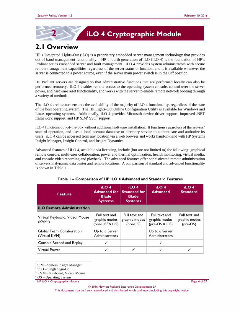
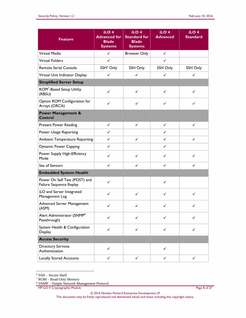
Advanced features of iLO 4, available via licensing, include (but are not limited to) the following: graphical
remote console, multi-user collaboration, power and thermal optimization, health monitoring, virtual media,
and console video recording and playback. The advanced features offer sophisticated remote administration
of servers in dynamic data center and remote locations. A comparison of standard and advanced functionality
is shown in Table 1.
Table 1 – Comparison of HP iLO 4 Advanced and Standard Features
Feature
iLO 4
Advanced for
Blade
Systems
iLO 4
Standard for
Blade
Systems
iLO 4
Advanced
iLO 4
Standard
iLO Remote Administration
Virtual Keyboard, Video, Mouse
(KVM3)
Full text and
graphic modes
(pre-OS4 & OS)
Full text and
graphic modes
(pre-OS)
Full text and
graphic modes
(pre-OS & OS)
Full text and
graphic modes
(pre-OS)
Global Team Collaboration
(Virtual KVM)
Up to 6 Server
Administrators
Up to 6 Server
Administrators
Console Record and Replay
Virtual Power
1 SIM – System Insight Manager 2 SSO – Single Sign-On 3 KVM – Keyboard, Video, Mouse 4 OS – Operating System
Security Policy, Version 1.2 February 10, 2016
HP iLO 4 Cryptographic Module Page 5 of 27
© 2016 Hewlett Packard Enterprise Development LP This document may be freely reproduced and distributed whole and intact including this copyright notice.
Feature
iLO 4
Advanced for
Blade
Systems
iLO 4
Standard for
Blade
Systems
iLO 4
Advanced
iLO 4
Standard
Virtual Media Browser Only
Virtual Folders
Remote Serial Console SSH6 Only SSH Only SSH Only SSH Only
Virtual Unit Indicator Display
Simplified Server Setup
ROM7-Based Setup Utility
(RBSU)
Option ROM Configuration for
Arrays (ORCA)
Power Management &
Control
Present Power Reading
Power Usage Reporting
Ambient Temperature Reporting
Dynamic Power Capping
Power Supply High-Efficiency
Mode
Sea of Sensors
Embedded System Health
Power On Self Test (POST) and
Failure Sequence Replay
iLO and Server Integrated
Management Log
Advanced Server Management
(ASM)
Alert Administrator (SNMP8
Passthrough)
System Health & Configuration
Display
Access Security
Directory Services
Authentication
Locally Stored Accounts
6 SSH – Secure Shell 7 ROM – Read-Only Memory 8 SNMP – Simple Network Management Protocol
Security Policy, Version 1.2 February 10, 2016
HP iLO 4 Cryptographic Module Page 6 of 27
© 2016 Hewlett Packard Enterprise Development LP This document may be freely reproduced and distributed whole and intact including this copyright notice.
Feature
iLO 4
Advanced for
Blade
Systems
iLO 4
Standard for
Blade
Systems
iLO 4
Advanced
iLO 4
Standard
Interfaces
Browser
Command Line
Extensible Markup Language
(XML)/Perl Scripting
Integrated Remote Console for
Windows Clients
Java Applet Client for Windows
and Linux Clients
Security Protocols
Transport Layer Security (TLS)
Secure Shell (SSH)
RC4/AES9 (Virtual KVM) 10
Network Connectivity
Dedicated Network Interface
Controller (NIC)
Shared Network Port
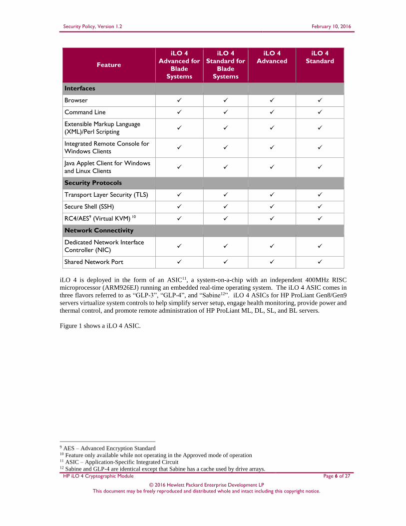
iLO 4 is deployed in the form of an ASIC11, a system-on-a-chip with an independent 400MHz RISC
microprocessor (ARM926EJ) running an embedded real-time operating system. The iLO 4 ASIC comes in
three flavors referred to as “GLP-3”, “GLP-4”, and “Sabine12”. iLO 4 ASICs for HP ProLiant Gen8/Gen9
servers virtualize system controls to help simplify server setup, engage health monitoring, provide power and
thermal control, and promote remote administration of HP ProLiant ML, DL, SL, and BL servers.
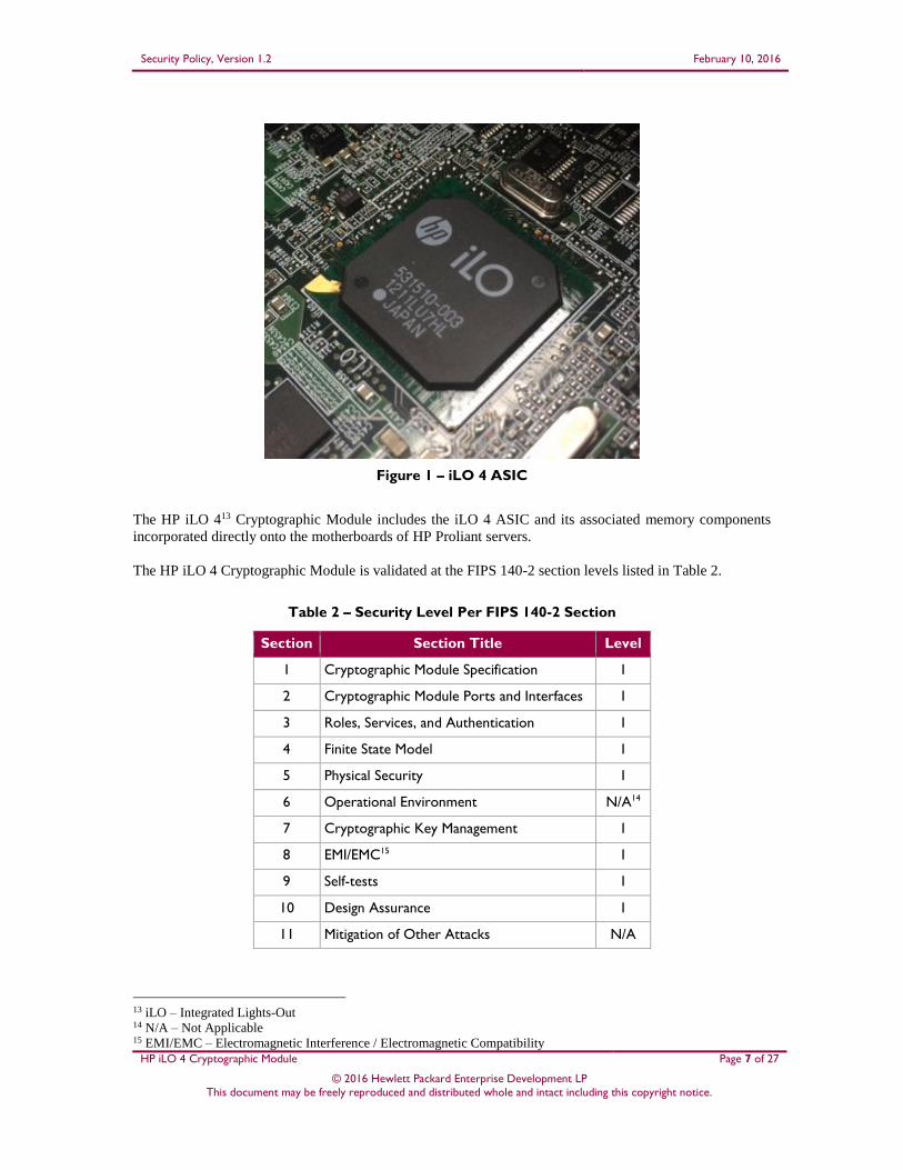
Figure 1 shows a iLO 4 ASIC.
9 AES – Advanced Encryption Standard 10 Feature only available while not operating in the Approved mode of operation 11 ASIC – Application-Specific Integrated Circuit 12 Sabine and GLP-4 are identical except that Sabine has a cache used by drive arrays.
Security Policy, Version 1.2 February 10, 2016
HP iLO 4 Cryptographic Module Page 7 of 27
© 2016 Hewlett Packard Enterprise Development LP This document may be freely reproduced and distributed whole and intact including this copyright notice.
Figure 1 – iLO 4 ASIC
The HP iLO 413 Cryptographic Module includes the iLO 4 ASIC and its associated memory components
incorporated directly onto the motherboards of HP Proliant servers.
The HP iLO 4 Cryptographic Module is validated at the FIPS 140-2 section levels listed in Table 2.
Table 2 – Security Level Per FIPS 140-2 Section
Section Section Title Level
1 Cryptographic Module Specification 1
2 Cryptographic Module Ports and Interfaces 1
3 Roles, Services, and Authentication 1
4 Finite State Model 1
5 Physical Security 1
6 Operational Environment N/A14
7 Cryptographic Key Management 1
8 EMI/EMC15 1
9 Self-tests 1
10 Design Assurance 1
11 Mitigation of Other Attacks N/A
13 iLO – Integrated Lights-Out 14 N/A – Not Applicable 15 EMI/EMC – Electromagnetic Interference / Electromagnetic Compatibility
Security Policy, Version 1.2 February 10, 2016
HP iLO 4 Cryptographic Module Page 8 of 27
© 2016 Hewlett Packard Enterprise Development LP This document may be freely reproduced and distributed whole and intact including this copyright notice.
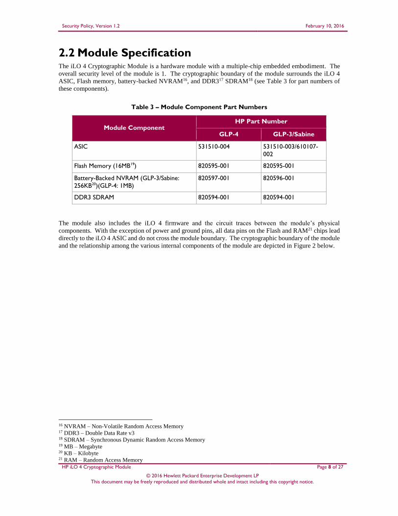
2.2 Module Specification The iLO 4 Cryptographic Module is a hardware module with a multiple-chip embedded embodiment. The
overall security level of the module is 1. The cryptographic boundary of the module surrounds the iLO 4
ASIC, Flash memory, battery-backed NVRAM16, and DDR317 SDRAM18 (see Table 3 for part numbers of
these components).
Table 3 – Module Component Part Numbers
Module Component HP Part Number
GLP-4 GLP-3/Sabine
ASIC 531510-004 531510-003/610107-
002
Flash Memory (16MB19) 820595-001 820595-001
Battery-Backed NVRAM (GLP-3/Sabine:
256KB20)(GLP-4: 1MB)
820597-001 820596-001
DDR3 SDRAM 820594-001 820594-001
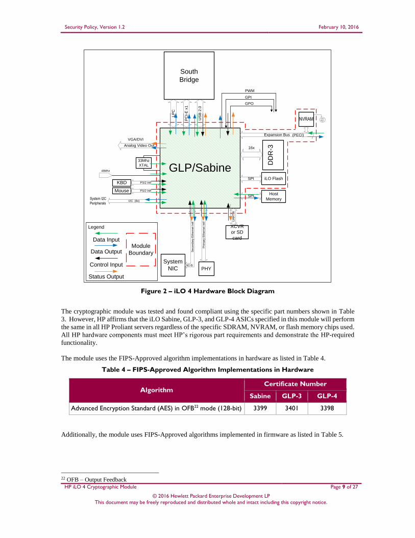
The module also includes the iLO 4 firmware and the circuit traces between the module’s physical
components. With the exception of power and ground pins, all data pins on the Flash and RAM21 chips lead
directly to the iLO 4 ASIC and do not cross the module boundary. The cryptographic boundary of the module
and the relationship among the various internal components of the module are depicted in Figure 2 below.
16 NVRAM – Non-Volatile Random Access Memory 17 DDR3 – Double Data Rate v3 18 SDRAM – Synchronous Dynamic Random Access Memory 19 MB – Megabyte 20 KB – Kilobyte 21 RAM – Random Access Memory
Security Policy, Version 1.2 February 10, 2016
HP iLO 4 Cryptographic Module Page 9 of 27
© 2016 Hewlett Packard Enterprise Development LP This document may be freely reproduced and distributed whole and intact including this copyright notice.
GLP/Sabine
PC
I-E
x1
DD
R-3
SPI
Prim
ary
Eth
ern
et In
tf
PHY
System
NIC
South
Bridge
iLO Flash
LP
C
KBD
16x
Expansion Bus
US
B 2
.0
PS/2 Intf
33Mhz
XTAL
48Mhz
SPIHost
Memory
NVRAM
GPO
GPI
PWM
UA
RT
A
NC-SI
Se
co
nd
ary
Eth
ern
et In
tfMouse PS/2 Intf
I2C (8x)System I2C
Peripherals
Analog Video Out
Legend
Data Output
Status Output
Control Input
Data InputModule
Boundary
XCVR
or SD
card
VGA/DVI(PECI)
Figure 2 – iLO 4 Hardware Block Diagram
The cryptographic module was tested and found compliant using the specific part numbers shown in Table
3. However, HP affirms that the iLO Sabine, GLP-3, and GLP-4 ASICs specified in this module will perform
the same in all HP Proliant servers regardless of the specific SDRAM, NVRAM, or flash memory chips used.
All HP hardware components must meet HP’s rigorous part requirements and demonstrate the HP-required
functionality.
The module uses the FIPS-Approved algorithm implementations in hardware as listed in Table 4.
Table 4 – FIPS-Approved Algorithm Implementations in Hardware
Algorithm Certificate Number
Sabine GLP-3 GLP-4
Advanced Encryption Standard (AES) in OFB22 mode (128-bit) 3399 3401 3398
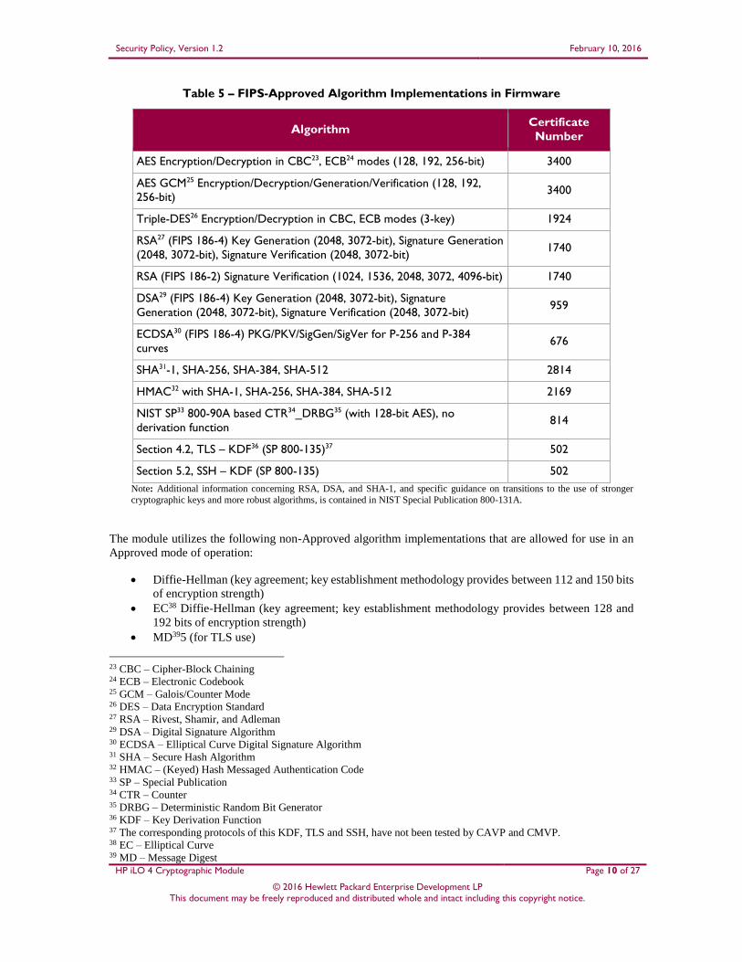
Additionally, the module uses FIPS-Approved algorithms implemented in firmware as listed in Table 5.
22 OFB – Output Feedback
Security Policy, Version 1.2 February 10, 2016
HP iLO 4 Cryptographic Module Page 10 of 27
© 2016 Hewlett Packard Enterprise Development LP This document may be freely reproduced and distributed whole and intact including this copyright notice.
Table 5 – FIPS-Approved Algorithm Implementations in Firmware
Algorithm Certificate
Number
AES Encryption/Decryption in CBC23, ECB24 modes (128, 192, 256-bit) 3400
AES GCM25 Encryption/Decryption/Generation/Verification (128, 192,
256-bit) 3400
Triple-DES26 Encryption/Decryption in CBC, ECB modes (3-key) 1924
RSA27 (FIPS 186-4) Key Generation (2048, 3072-bit), Signature Generation
(2048, 3072-bit), Signature Verification (2048, 3072-bit) 1740
RSA (FIPS 186-2) Signature Verification (1024, 1536, 2048, 3072, 4096-bit) 1740
DSA29 (FIPS 186-4) Key Generation (2048, 3072-bit), Signature
Generation (2048, 3072-bit), Signature Verification (2048, 3072-bit) 959
ECDSA30 (FIPS 186-4) PKG/PKV/SigGen/SigVer for P-256 and P-384
curves 676
SHA31-1, SHA-256, SHA-384, SHA-512 2814
HMAC32 with SHA-1, SHA-256, SHA-384, SHA-512 2169
NIST SP33 800-90A based CTR34_DRBG35 (with 128-bit AES), no
derivation function 814
Section 4.2, TLS – KDF36 (SP 800-135)37 502
Section 5.2, SSH – KDF (SP 800-135) 502
Note: Additional information concerning RSA, DSA, and SHA-1, and specific guidance on transitions to the use of stronger
cryptographic keys and more robust algorithms, is contained in NIST Special Publication 800-131A.
The module utilizes the following non-Approved algorithm implementations that are allowed for use in an
Approved mode of operation:
Diffie-Hellman (key agreement; key establishment methodology provides between 112 and 150 bits
of encryption strength)
EC38 Diffie-Hellman (key agreement; key establishment methodology provides between 128 and
192 bits of encryption strength)
MD395 (for TLS use)
23 CBC – Cipher-Block Chaining 24 ECB – Electronic Codebook 25 GCM – Galois/Counter Mode 26 DES – Data Encryption Standard 27 RSA – Rivest, Shamir, and Adleman 29 DSA – Digital Signature Algorithm 30 ECDSA – Elliptical Curve Digital Signature Algorithm 31 SHA – Secure Hash Algorithm 32 HMAC – (Keyed) Hash Messaged Authentication Code 33 SP – Special Publication 34 CTR – Counter 35 DRBG – Deterministic Random Bit Generator 36 KDF – Key Derivation Function 37 The corresponding protocols of this KDF, TLS and SSH, have not been tested by CAVP and CMVP. 38 EC – Elliptical Curve 39 MD – Message Digest
Security Policy, Version 1.2 February 10, 2016
HP iLO 4 Cryptographic Module Page 11 of 27
© 2016 Hewlett Packard Enterprise Development LP This document may be freely reproduced and distributed whole and intact including this copyright notice.
RSA (key wrapping; key establishment methodology provides between 112 and 256 bits of
encryption strength)
NDRNG40 used for entropy gathering
2.3 Module Interfaces iLO 4 offers a WebUI41 (accessible over TLS) and a Command Line (CLI) (accessible over SSH)
management interfaces. The module’s design separates the physical ports into five logically distinct
categories. They are:
Data Input
Data Output
Control Input
Status Output
Power
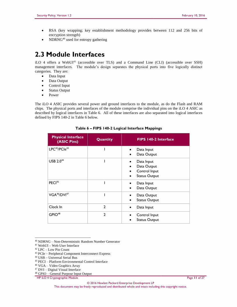
The iLO 4 ASIC provides several power and ground interfaces to the module, as do the Flash and RAM
chips. The physical ports and interfaces of the module comprise the individual pins on the iLO 4 ASIC as
described by logical interfaces in Table 6. All of these interfaces are also separated into logical interfaces
defined by FIPS 140-2 in Table 6 below.
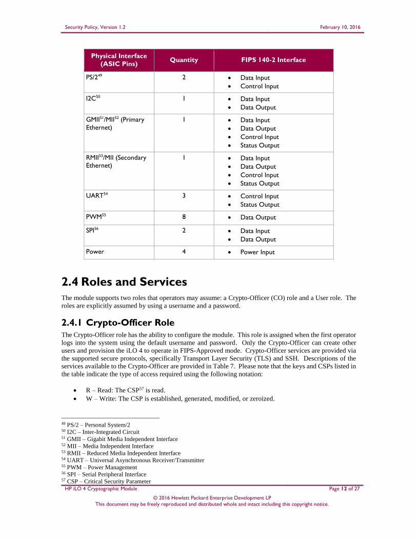
Table 6 – FIPS 140-2 Logical Interface Mappings
Physical Interface
(ASIC Pins) Quantity FIPS 140-2 Interface
LPC42/PCIe43 1 Data Input
Data Output
USB 2.044 1 Data Input
Data Output
Control Input
Status Output
PECI45 1 Data Input
Data Output
VGA46/DVI47 1 Data Output
Status Output
Clock In 2 Data Input
GPIO48 2 Control Input
Status Output
40 NDRNG – Non-Deterministic Random Number Generator 41 WebUI – Web User Interface 42 LPC – Low Pin Count 43 PCIe – Peripheral Component Interconnect Express 44 USB – Universal Serial Bus 45 PECI – Platform Environmental Control Interface 46 VGA – Video Graphics Array 47 DVI – Digital Visual Interface 48 GPIO – General Purpose Input Output
Security Policy, Version 1.2 February 10, 2016
HP iLO 4 Cryptographic Module Page 12 of 27
© 2016 Hewlett Packard Enterprise Development LP This document may be freely reproduced and distributed whole and intact including this copyright notice.
Physical Interface
(ASIC Pins) Quantity FIPS 140-2 Interface
PS/249 2 Data Input
Control Input
I2C50 1 Data Input
Data Output
GMII51/MII52 (Primary
Ethernet)
1 Data Input
Data Output
Control Input
Status Output
RMII53/MII (Secondary
Ethernet)
1 Data Input
Data Output
Control Input
Status Output
UART54 3 Control Input
Status Output
PWM55 8 Data Output
SPI56 2 Data Input
Data Output
Power 4 Power Input
2.4 Roles and Services
The module supports two roles that operators may assume: a Crypto-Officer (CO) role and a User role. The
roles are explicitly assumed by using a username and a password.
2.4.1 Crypto-Officer Role
The Crypto-Officer role has the ability to configure the module. This role is assigned when the first operator
logs into the system using the default username and password. Only the Crypto-Officer can create other
users and provision the iLO 4 to operate in FIPS-Approved mode. Crypto-Officer services are provided via
the supported secure protocols, specifically Transport Layer Security (TLS) and SSH. Descriptions of the
services available to the Crypto-Officer are provided in Table 7. Please note that the keys and CSPs listed in
the table indicate the type of access required using the following notation:
R – Read: The CSP57 is read.
W – Write: The CSP is established, generated, modified, or zeroized.
49 PS/2 – Personal System/2 50 I2C – Inter-Integrated Circuit 51 GMII – Gigabit Media Independent Interface 52 MII – Media Independent Interface 53 RMII – Reduced Media Independent Interface 54 UART – Universal Asynchronous Receiver/Transmitter 55 PWM – Power Management 56 SPI – Serial Peripheral Interface 57 CSP – Critical Security Parameter
Security Policy, Version 1.2 February 10, 2016
HP iLO 4 Cryptographic Module Page 13 of 27
© 2016 Hewlett Packard Enterprise Development LP This document may be freely reproduced and distributed whole and intact including this copyright notice.
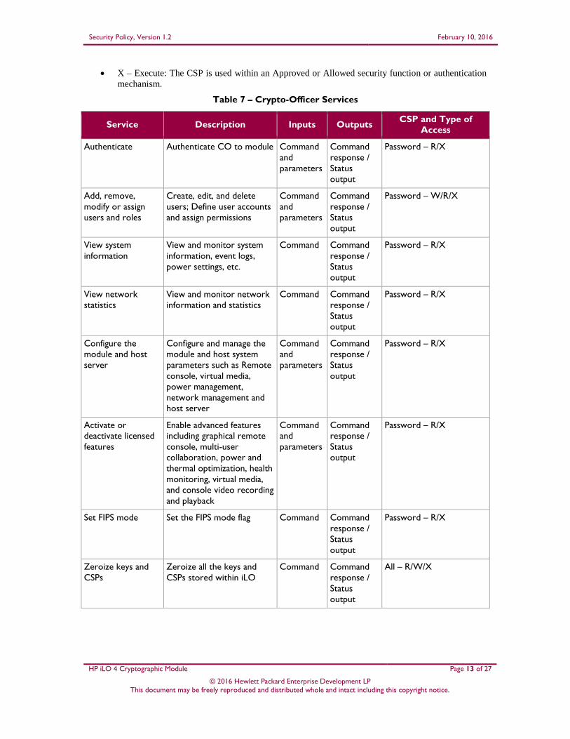
X – Execute: The CSP is used within an Approved or Allowed security function or authentication
mechanism.
Table 7 – Crypto-Officer Services
Service Description Inputs Outputs CSP and Type of
Access
Authenticate Authenticate CO to module Command
and
parameters
Command
response /
Status
output
Password – R/X
Add, remove,
modify or assign
users and roles
Create, edit, and delete
users; Define user accounts
and assign permissions
Command
and
parameters
Command
response /
Status
output
Password – W/R/X
View system
information
View and monitor system
information, event logs,
power settings, etc.
Command Command
response /
Status
output
Password – R/X
View network
statistics
View and monitor network
information and statistics
Command Command
response /
Status
output
Password – R/X
Configure the
module and host
server
Configure and manage the
module and host system
parameters such as Remote
console, virtual media,
power management,
network management and
host server
Command
and
parameters
Command
response /
Status
output
Password – R/X
Activate or
deactivate licensed
features
Enable advanced features
including graphical remote
console, multi-user
collaboration, power and
thermal optimization, health
monitoring, virtual media,
and console video recording
and playback
Command
and
parameters
Command
response /
Status
output
Password – R/X
Set FIPS mode Set the FIPS mode flag Command Command
response /
Status
output
Password – R/X
Zeroize keys and
CSPs
Zeroize all the keys and
CSPs stored within iLO
Command Command
response /
Status
output
All – R/W/X
Security Policy, Version 1.2 February 10, 2016
HP iLO 4 Cryptographic Module Page 14 of 27
© 2016 Hewlett Packard Enterprise Development LP This document may be freely reproduced and distributed whole and intact including this copyright notice.
Service Description Inputs Outputs CSP and Type of
Access
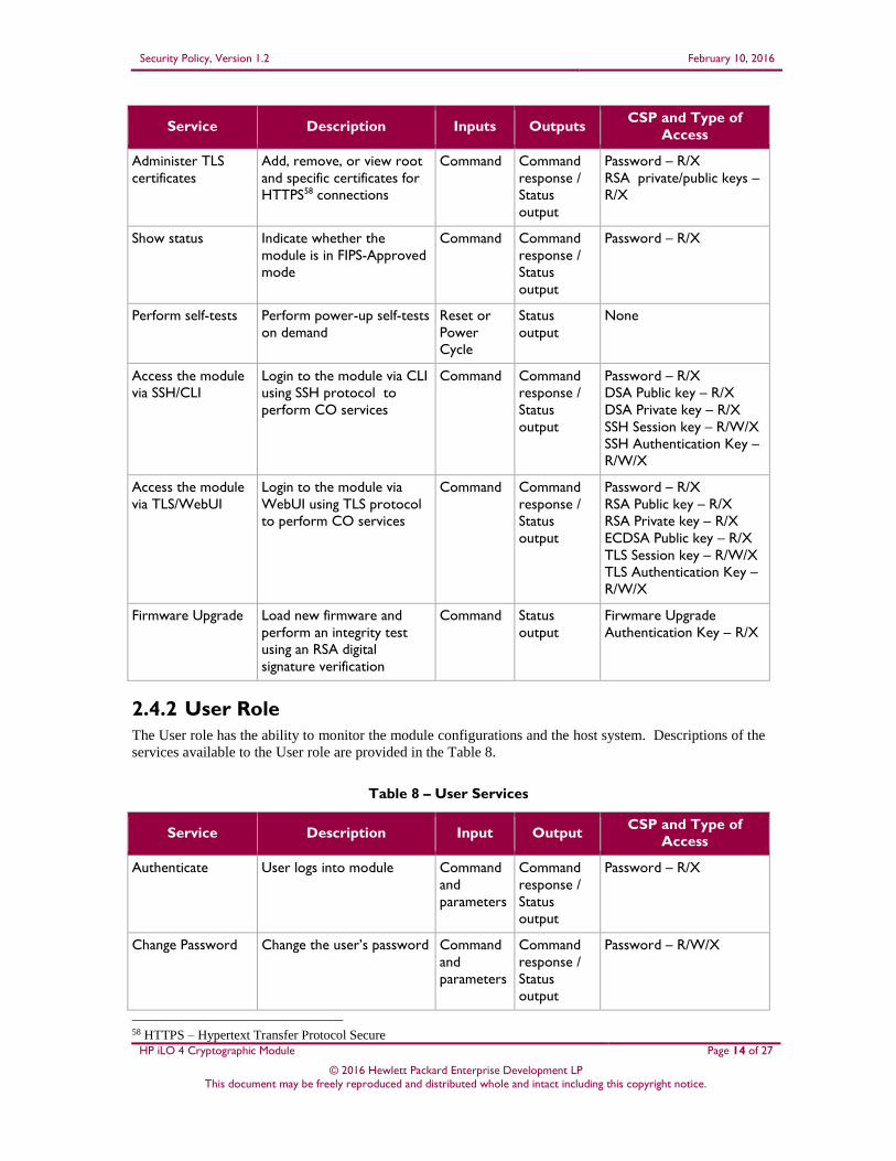
Administer TLS
certificates
Add, remove, or view root
and specific certificates for
HTTPS58 connections
Command Command
response /
Status
output
Password – R/X
RSA private/public keys –
R/X
Show status Indicate whether the
module is in FIPS-Approved
mode
Command Command
response /
Status
output
Password – R/X
Perform self-tests Perform power-up self-tests
on demand
Reset or
Power
Cycle
Status
output
None
Access the module
via SSH/CLI
Login to the module via CLI
using SSH protocol to
perform CO services
Command Command
response /
Status
output
Password – R/X
DSA Public key – R/X
DSA Private key – R/X
SSH Session key – R/W/X
SSH Authentication Key –
R/W/X
Access the module
via TLS/WebUI
Login to the module via
WebUI using TLS protocol
to perform CO services
Command Command
response /
Status
output
Password – R/X
RSA Public key – R/X
RSA Private key – R/X
ECDSA Public key – R/X
TLS Session key – R/W/X
TLS Authentication Key –
R/W/X
Firmware Upgrade Load new firmware and
perform an integrity test
using an RSA digital
signature verification
Command Status
output
Firwmare Upgrade
Authentication Key – R/X
2.4.2 User Role
The User role has the ability to monitor the module configurations and the host system. Descriptions of the
services available to the User role are provided in the Table 8.
Table 8 – User Services
Service Description Input Output CSP and Type of
Access
Authenticate User logs into module Command
and
parameters
Command
response /
Status
output
Password – R/X
Change Password Change the user’s password Command
and
parameters
Command
response /
Status
output
Password – R/W/X
58 HTTPS – Hypertext Transfer Protocol Secure
Security Policy, Version 1.2 February 10, 2016
HP iLO 4 Cryptographic Module Page 15 of 27
© 2016 Hewlett Packard Enterprise Development LP This document may be freely reproduced and distributed whole and intact including this copyright notice.
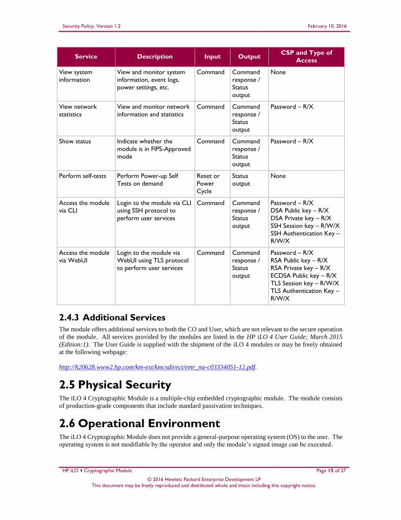
Service Description Input Output CSP and Type of
Access
View system
information
View and monitor system
information, event logs,
power settings, etc.
Command Command
response /
Status
output
None
View network
statistics
View and monitor network
information and statistics
Command Command
response /
Status
output
Password – R/X
Show status Indicate whether the
module is in FIPS-Approved
mode
Command Command
response /
Status
output
Password – R/X
Perform self-tests Perform Power-up Self
Tests on demand
Reset or
Power
Cycle
Status
output
None
Access the module
via CLI
Login to the module via CLI
using SSH protocol to
perform user services
Command Command
response /
Status
output
Password – R/X
DSA Public key – R/X
DSA Private key – R/X
SSH Session key – R/W/X
SSH Authentication Key –
R/W/X
Access the module
via WebUI
Login to the module via
WebUI using TLS protocol
to perform user services
Command Command
response /
Status
output
Password – R/X
RSA Public key – R/X
RSA Private key – R/X
ECDSA Public key – R/X
TLS Session key – R/W/X
TLS Authentication Key –
R/W/X
2.4.3 Additional Services
The module offers additional services to both the CO and User, which are not relevant to the secure operation
of the module. All services provided by the modules are listed in the HP iLO 4 User Guide; March 2015
(Edition:1). The User Guide is supplied with the shipment of the iLO 4 modules or may be freely obtained
at the following webpage:
http://h20628.www2.hp.com/km-ext/kmcsdirect/emr_na-c03334051-12.pdf.
2.5 Physical Security The iLO 4 Cryptographic Module is a multiple-chip embedded cryptographic module. The module consists
of production-grade components that include standard passivation techniques.
2.6 Operational Environment The iLO 4 Cryptographic Module does not provide a general-purpose operating system (OS) to the user. The
operating system is not modifiable by the operator and only the module’s signed image can be executed.
Security Policy, Version 1.2 February 10, 2016
HP iLO 4 Cryptographic Module Page 16 of 27
© 2016 Hewlett Packard Enterprise Development LP This document may be freely reproduced and distributed whole and intact including this copyright notice.
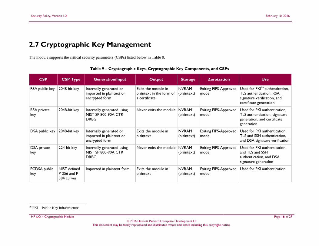
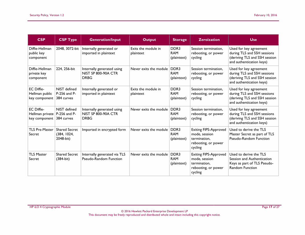
2.7 Cryptographic Key Management
The module supports the critical security parameters (CSPs) listed below in Table 9.
Table 9 – Cryptographic Keys, Cryptographic Key Components, and CSPs
CSP CSP Type Generation/Input Output Storage Zeroization Use
RSA public key 2048-bit key Internally generated or
imported in plaintext or
encrypted form
Exits the module in
plaintext in the form of
a certificate
NVRAM
(plaintext)
Exiting FIPS-Approved
mode
Used for PKI59 authentication,
TLS authentication, RSA
signature verification, and
certificate generation
RSA private
key
2048-bit key Internally generated using
NIST SP 800-90A CTR
DRBG
Never exits the module NVRAM
(plaintext)
Exiting FIPS-Approved
mode
Used for PKI authentication,
TLS authentication, signature
generation, and certificate
generation
DSA public key 2048-bit key Internally generated or
imported in plaintext or
encrypted form
Exits the module in
plaintext
NVRAM
(plaintext)
Exiting FIPS-Approved
mode
Used for PKI authentication,
TLS and SSH authentication,
and DSA signature verification
DSA private
key
224-bit key Internally generated using
NIST SP 800-90A CTR
DRBG
Never exits the module NVRAM
(plaintext)
Exiting FIPS-Approved
mode
Used for PKI authentication,
and TLS and SSH
authentication, and DSA
signature generation
ECDSA public
key
NIST defined
P-256 and P-
384 curves
Imported in plaintext form Exits the module in
plaintext
NVRAM
(plaintext)
Exiting FIPS-Approved
mode
Used for PKI authentication
59 PKI – Public Key Infrastructure
Security Policy, Version 1.2 February 10, 2016
HP iLO 4 Cryptographic Module Page 17 of 27
© 2016 Hewlett Packard Enterprise Development LP This document may be freely reproduced and distributed whole and intact including this copyright notice.
CSP CSP Type Generation/Input Output Storage Zeroization Use
Diffie-Hellman
public key
component
2048, 3072-bit Internally generated or
imported in plaintext
Exits the module in
plaintext
DDR3
RAM
(plaintext)
Session termination,
rebooting, or power
cycling
Used for key agreement
during TLS and SSH sessions
(deriving TLS and SSH session
and authentication keys)
Diffie-Hellman
private key
component
224, 256-bit Internally generated using
NIST SP 800-90A CTR
DRBG
Never exits the module DDR3
RAM
(plaintext)
Session termination,
rebooting, or power
cycling
Used for key agreement
during TLS and SSH sessions
(deriving TLS and SSH session
and authentication keys)
EC Diffie-
Hellman public
key component
NIST defined
P-256 and P-
384 curves
Internally generated or
imported in plaintext
Exits the module in
plaintext
DDR3
RAM
(plaintext)
Session termination,
rebooting, or power
cycling
Used for key agreement
during TLS and SSH sessions
(deriving TLS and SSH session
and authentication keys)
EC Diffie-
Hellman private
key component
NIST defined
P-256 and P-
384 curves
Internally generated using
NIST SP 800-90A CTR
DRBG
Never exits the module DDR3
RAM
(plaintext)
Session termination,
rebooting, or power
cycling
Used for key agreement
during TLS and SSH sessions
(deriving TLS and SSH session
and authentication keys)
TLS Pre-Master
Secret
Shared Secret
(384, 1024,
2048-bit)
Imported in encrypted form Never exits the module DDR3
RAM
(plaintext)
Exiting FIPS-Approved
mode, session
termination,
rebooting, or power
cycling
Used to derive the TLS
Master Secret as part of TLS
Pseudo-Random Function
TLS Master
Secret
Shared Secret
(384-bit)
Internally generated via TLS
Pseudo-Random Function
Never exits the module DDR3
RAM
(plaintext)
Exiting FIPS-Approved
mode, session
termination,
rebooting, or power
cycling
Used to derive the TLS
Session and Authentication
Keys as part of TLS Pseudo-
Random Function
Security Policy, Version 1.2 February 10, 2016
HP iLO 4 Cryptographic Module Page 18 of 27
© 2016 Hewlett Packard Enterprise Development LP This document may be freely reproduced and distributed whole and intact including this copyright notice.
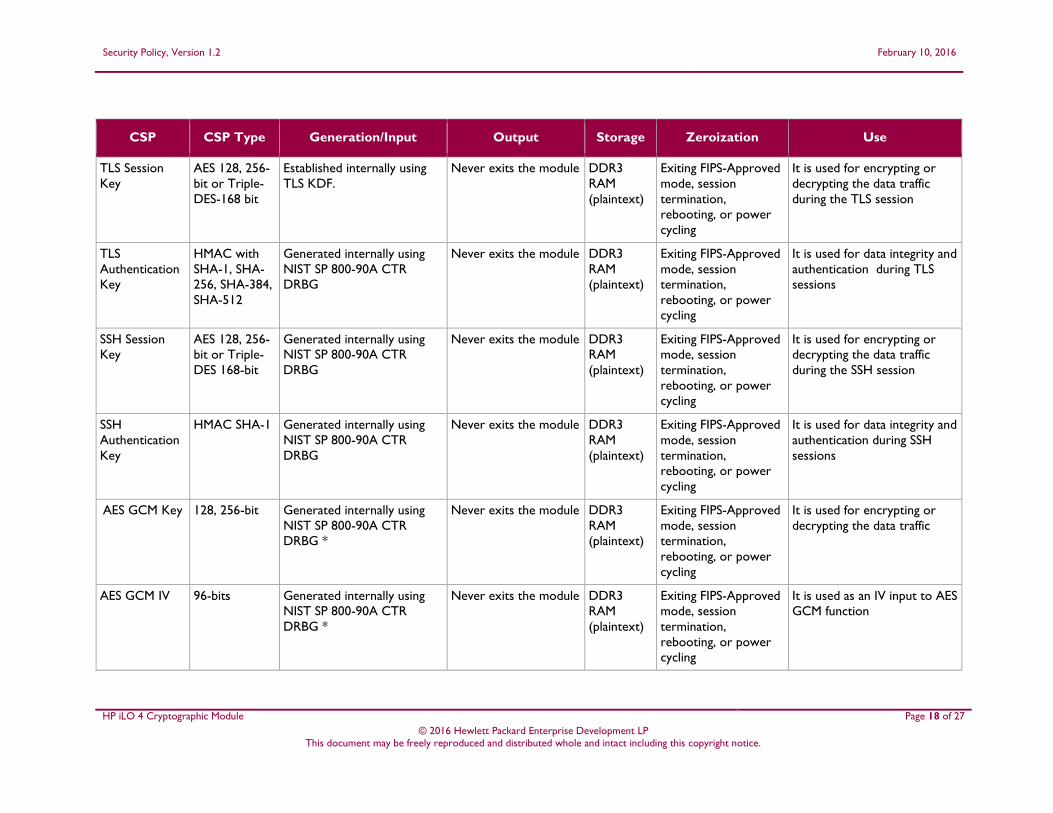
CSP CSP Type Generation/Input Output Storage Zeroization Use
TLS Session
Key
AES 128, 256-
bit or Triple-
DES-168 bit
Established internally using
TLS KDF.
Never exits the module DDR3
RAM
(plaintext)
Exiting FIPS-Approved
mode, session
termination,
rebooting, or power
cycling
It is used for encrypting or
decrypting the data traffic
during the TLS session
TLS
Authentication
Key
HMAC with
SHA-1, SHA-
256, SHA-384,
SHA-512
Generated internally using
NIST SP 800-90A CTR
DRBG
Never exits the module DDR3
RAM
(plaintext)
Exiting FIPS-Approved
mode, session
termination,
rebooting, or power
cycling
It is used for data integrity and
authentication during TLS
sessions
SSH Session
Key
AES 128, 256-
bit or Triple-
DES 168-bit
Generated internally using
NIST SP 800-90A CTR
DRBG
Never exits the module DDR3
RAM
(plaintext)
Exiting FIPS-Approved
mode, session
termination,
rebooting, or power
cycling
It is used for encrypting or
decrypting the data traffic
during the SSH session
SSH
Authentication
Key
HMAC SHA-1 Generated internally using
NIST SP 800-90A CTR
DRBG
Never exits the module DDR3
RAM
(plaintext)
Exiting FIPS-Approved
mode, session
termination,
rebooting, or power
cycling
It is used for data integrity and
authentication during SSH
sessions
AES GCM Key 128, 256-bit Generated internally using
NIST SP 800-90A CTR
DRBG *
Never exits the module DDR3
RAM
(plaintext)
Exiting FIPS-Approved
mode, session
termination,
rebooting, or power
cycling
It is used for encrypting or
decrypting the data traffic
AES GCM IV 96-bits Generated internally using
NIST SP 800-90A CTR
DRBG *
Never exits the module DDR3
RAM
(plaintext)
Exiting FIPS-Approved
mode, session
termination,
rebooting, or power
cycling
It is used as an IV input to AES
GCM function
Security Policy, Version 1.2 February 10, 2016
HP iLO 4 Cryptographic Module Page 19 of 27
© 2016 Hewlett Packard Enterprise Development LP This document may be freely reproduced and distributed whole and intact including this copyright notice.
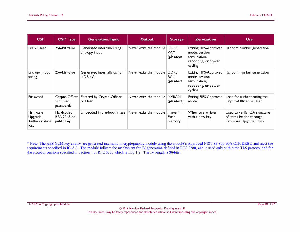
CSP CSP Type Generation/Input Output Storage Zeroization Use
DRBG seed 256-bit value Generated internally using
entropy input
Never exits the module DDR3
RAM
(plaintext
Exiting FIPS-Approved
mode, session
termination,
rebooting, or power
cycling
Random number generation
Entropy Input
string
256-bit value Generated internally using
NDRNG
Never exits the module DDR3
RAM
(plaintext
Exiting FIPS-Approved
mode, session
termination,
rebooting, or power
cycling
Random number generation
Password Crypto-Officer
and User
passwords
Entered by Crypto-Officer
or User
Never exits the module NVRAM
(plaintext)
Exiting FIPS-Approved
mode
Used for authenticating the
Crypto-Officer or User
Firmware
Upgrade
Authentication
Key
Hardcoded
RSA 2048-bit
public key
Embedded in pre-boot image Never exits the module Image in
Flash
memory
When overwritten
with a new key
Used to verify RSA signature
of items loaded through
Firmware Upgrade utility
* Note: The AES GCM key and IV are generated internally in cryptographic module using the module’s Approved NIST SP 800-90A CTR DRBG and meet the
requirements specified in IG A.5. The module follows the mechanism for IV generation defined in RFC 5288, and is used only within the TLS protocol and for
the protocol versions specified in Section 4 of RFC 5288 which is TLS 1.2. The IV length is 96-bits.
Security Policy, Version 1.2 February 10, 2016
HP iLO 4 Cryptographic Module Page 20 of 27
© 2016 Hewlett Packard Enterprise Development LP This document may be freely reproduced and distributed whole and intact including this copyright notice.
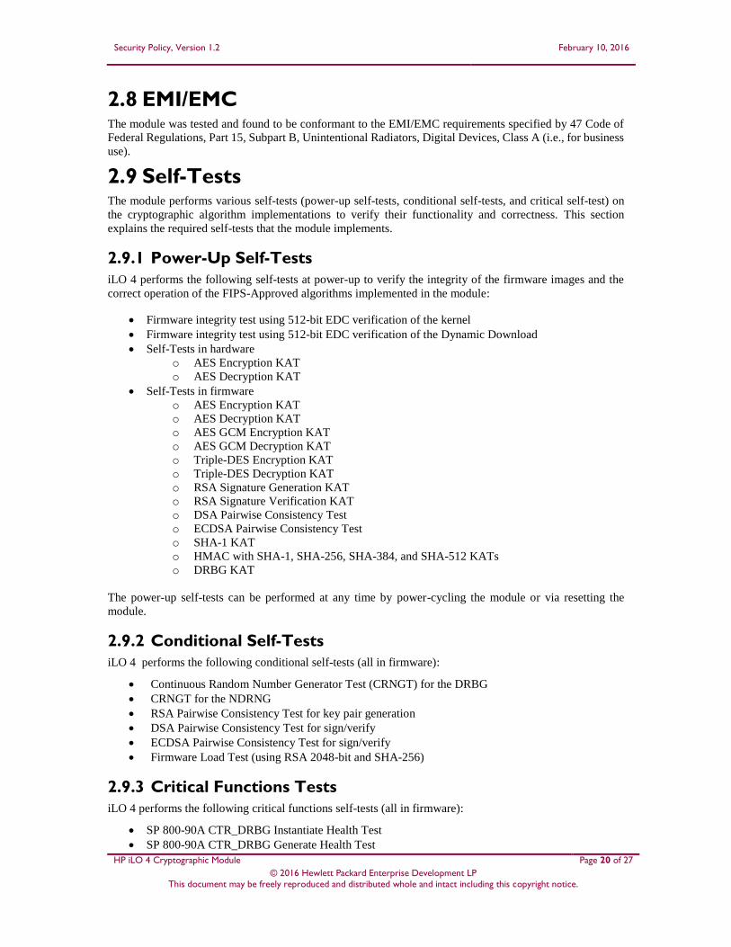
2.8 EMI/EMC The module was tested and found to be conformant to the EMI/EMC requirements specified by 47 Code of
Federal Regulations, Part 15, Subpart B, Unintentional Radiators, Digital Devices, Class A (i.e., for business
use).
2.9 Self-Tests The module performs various self-tests (power-up self-tests, conditional self-tests, and critical self-test) on
the cryptographic algorithm implementations to verify their functionality and correctness. This section
explains the required self-tests that the module implements.
2.9.1 Power-Up Self-Tests
iLO 4 performs the following self-tests at power-up to verify the integrity of the firmware images and the
correct operation of the FIPS-Approved algorithms implemented in the module:
Firmware integrity test using 512-bit EDC verification of the kernel
Firmware integrity test using 512-bit EDC verification of the Dynamic Download
Self-Tests in hardware
o AES Encryption KAT
o AES Decryption KAT
Self-Tests in firmware
o AES Encryption KAT
o AES Decryption KAT
o AES GCM Encryption KAT
o AES GCM Decryption KAT
o Triple-DES Encryption KAT
o Triple-DES Decryption KAT
o RSA Signature Generation KAT
o RSA Signature Verification KAT
o DSA Pairwise Consistency Test
o ECDSA Pairwise Consistency Test
o SHA-1 KAT
o HMAC with SHA-1, SHA-256, SHA-384, and SHA-512 KATs
o DRBG KAT
The power-up self-tests can be performed at any time by power-cycling the module or via resetting the
module.
2.9.2 Conditional Self-Tests
iLO 4 performs the following conditional self-tests (all in firmware):
Continuous Random Number Generator Test (CRNGT) for the DRBG
CRNGT for the NDRNG
RSA Pairwise Consistency Test for key pair generation
DSA Pairwise Consistency Test for sign/verify
ECDSA Pairwise Consistency Test for sign/verify
Firmware Load Test (using RSA 2048-bit and SHA-256)
2.9.3 Critical Functions Tests
iLO 4 performs the following critical functions self-tests (all in firmware):
SP 800-90A CTR_DRBG Instantiate Health Test
SP 800-90A CTR_DRBG Generate Health Test
Security Policy, Version 1.2 February 10, 2016
HP iLO 4 Cryptographic Module Page 21 of 27
© 2016 Hewlett Packard Enterprise Development LP This document may be freely reproduced and distributed whole and intact including this copyright notice.
SP 800-90A CTR_DRBG Reseed Health Test
SP 800-90A CTR_DRBG Uninstantiate Health Test
2.9.4 Self-Test Failure Handling
Upon failure of any power-up self-test, conditional self-test, or critical function test, the module demonstrates
the following behavior:
On failure of firmware intergrity test, the module reaches “ Boot Error” state in which the module
firmware does not get loaded and the module aborts. The only way to continue from this state is by
rebooting or power-cycling the module. If the error still exists, then the module needs to be returned
to the factory.
In case of failure of any other self-test, the module reaches the “Critical Error” state and it disables
all access to cryptographic functions and CSPs. All data outputs via data output interfaces are
inhibited upon any self-test failure. A permanent error status will be relayed via the status output
interface, which then is recorded as an entry to the module log file and also relayed via the status
output interfaces. The module then zeroizes all the keys and CSPs, performs a reset to factory default
settings, and performs a reboot. The factory default reset changes the FIPS mode flag, taking the
module out of FIPS mode. The module will have to be reset in order to reconfigure the module to
FIPS mode.
2.10 Mitigation of Other Attacks This section is not applicable. The module does not claim to mitigate any attacks beyond the FIPS 140-2
Level 1 requirements for this validation.
Security Policy, Version 1.2 February 10, 2016
HP iLO 4 Cryptographic Module Page 22 of 27
© 2016 Hewlett Packard Enterprise Development LP This document may be freely reproduced and distributed whole and intact including this copyright notice.
3 Secure Operation The iLO 4 Cryptographic Module meets Level 1 requirements for FIPS 140-2. The sections below describe
how to place and keep the module in its FIPS-Approved mode of operation.
3.1 Crypto-Officer Guidance The following sections provide the necessary step-by-step instructions for the secure installation of iLO 4 card, as well as the steps necessary to configure the module for a FIPS-Approved mode of operation.
3.1.1 Initialization
The module is delivered in an uninitialized factory state, and require first-time configuration in order to
operate in its FIPS-Approved mode. Access to the module shall be limited to the Crypto-Officer, and it is
the Crypto-Officer’s responsibility to configure the module into the FIPS-Approved mode. iLO 4 contains a
distinct FIPS-Approved mode of operation that can be set through the configuration of a single parameter
during initial initialization. The following sections provide the necessary step-by-step instructions for the
secure installation of the iLO 4, as well as the steps necessary to configure the module for a FIPS-Approved
mode of operation.
Once the host platform is properly installed, the Crypto-Officer shall immediately configure iLO 4 to operate
in FIPS-Approved mode; it is expected that iLO 4 will be configured for FIPS-Approved mode only once
during initial host platform installation. Exiting the FIPS-Approved mode will initiate a factory-reset of the
module, zeroizing all keys, CSPs, and user accounts.
The following steps outline the procedure for configuring iLO 4 to run in FIPS-Approved mode:
1. Access the iLO 4 over the Ethernet port via WebUI (over TLS).
2. Use the default username and password provided on the server tag along with the iLO 4 server to
log on. Accept the certificate.
3. Under the “Administration” menu click on “Security” sub-menu. Under the “Security” sub-menu
navigate to the “Encryption” tab.
4. Under the Encryption Enforcement Settings, select the “Enabled” option of the drop down menu for
the “FIPS Mode”.
5. iLO 4 will wipe the memories, reinitialize (zeroizing all existing keying material), and reboot.
6. Access the iLO again, using the first two steps outlined above.
7. Accept the new certificate.
8. Use the default username and password provided on the server tag along with the iLO 4 server to
log on.
9. Under the “Administration” menu, click on the “User Administration” sub-menu. Check the box
next to “Administrator”, under Local Users, and click the “Edit” button. Enter a new password in
the “Password” text box. Reenter the password, to confirm, in the “Password Confirm” text box.
Click the “Update User” button at the bottom of the page.
10. Under the “Administration” menu, click on the “Management” sub-menu. The “SNMP Settings”
tab contains SNMP configuration data. In the “Insight Management Integration” area, change the
value of “Level of Data Returned” to “Disabled (No Response to Request)”. Click “Apply”. This
disables “Insight Management Integration”.
11. The SNMP and its settings are disabled by default. Do not change default SNMP settings.
12. Under the “Administration” menu, click on the “Access Settings” sub-menu. Uncheck the checkbox
for “Enable IPMI/DCMI over LAN on Port 623”. Click “Apply”. This disables IPMI.
The module is now initialized and in FIPS-Approved mode.
Security Policy, Version 1.2 February 10, 2016
HP iLO 4 Cryptographic Module Page 23 of 27
© 2016 Hewlett Packard Enterprise Development LP This document may be freely reproduced and distributed whole and intact including this copyright notice.
3.1.2 Secure Management
A CO shall change the default password after first login. When a module is powered on for the first time, a
CO shall configure the module for FIPS mode by following the steps mentioned in Section 3.1.1.
Additionally, the following usage policies apply:
SNMP and IPMI shall be disabled while the module is running in the FIPS-Approved mode of
operation.
The CO shall not enter the DSA or RSA public keys manually while the module is operating in the
FIPS-Approved mode.
Remote administration must only be performed over the WebUI (HTTPS) and CLI (SSH) interfaces.
Once the module is provisioned into FIPS mode during initialization, the module will operate and remain in
FIPS-Approved mode of operation unless the module enters an error state and performs a factory reset. The
Crypto-Officer can also exit FIPS-Approved mode on demand by restoring the module to factory default.
In order to check the module’s FIPS mode status, the Crypto-Officer can check the “iLO Event Log” page,
under the “Information” header. In the “Description” column of the event log, the text “FIPS Mode Enabled.”
should appear at the time when the iLO was powered on or the status was changed to enable it.
3.2 User Guidance The User does not have the ability to configure sensitive information on the module, with the exception of
their password. The User must be diligent to pick strong passwords, and must not reveal their password to
anyone. Additionally, the User should be careful to protect any secret/private keys in their possession, if any.
The module requires 256-bits of entropy to generate a seed for the RNG. After initial startup the system must
be operational for one minute 50 seconds to generate enough entropy for the seeding function. Once
operational for this timeframe the module can be configured in FIPS approved mode.
3.3 Module’s Mode of Operation On the first power up, the module is not configured in its Approved mode. During initial configuration and
setup, the module is explicitly set to operate in the FIPS-Approved mode of operation. An authorized
operator can access the module via the WebUI or the CLI and determine the operational mode of the module.
Detailed steps and procedure required to determine whether the module is operating in FIPS-Approved mode
or not can be found in the “Enabling FIPS Mode” section of the iLO User’s Guide, which is available at
http://www.hp.com/support/ilo4_ug_en.
3.4 Non-Approved Mode When initialized and configured according to the Crypto-Officer guidance in this Security Policy, the
modules do not support a non-Approved mode of operation.
Security Policy, Version 1.2 February 10, 2016
HP iLO 4 Cryptographic Module Page 24 of 27
© 2016 Hewlett Packard Enterprise Development LP This document may be freely reproduced and distributed whole and intact including this copyright notice.
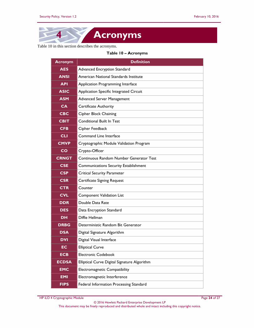
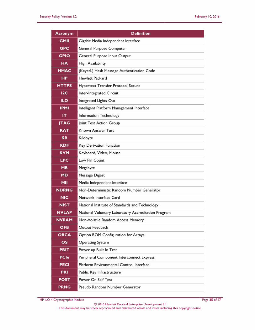
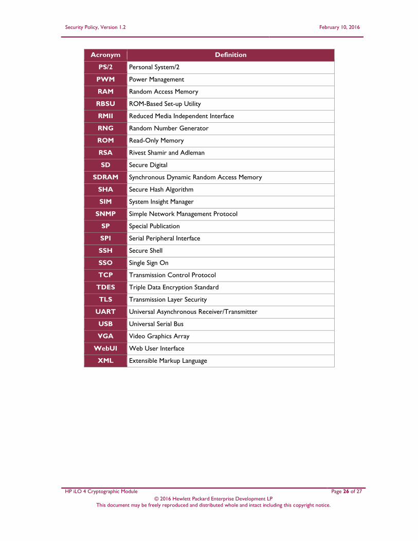
4 Acronyms Table 10 in this section describes the acronyms.
Table 10 – Acronyms
Acronym Definition
AES Advanced Encryption Standard
ANSI American National Standards Institute
API Application Programming Interface
ASIC Application Specific Integrated Circuit
ASM Advanced Server Management
CA Certificate Authority
CBC Cipher Block Chaining
CBIT Conditional Built In Test
CFB Cipher Feedback
CLI Command Line Interface
CMVP Cryptographic Module Validation Program
CO Crypto-Officer
CRNGT Continuous Random Number Generator Test
CSE Communications Security Establishment
CSP Critical Security Parameter
CSR Certificate Signing Request
CTR Counter
CVL Component Validation List
DDR Double Data Rate
DES Data Encryption Standard
DH Diffie Hellman
DRBG Deterministic Random Bit Generator
DSA Digital Signature Algorithm
DVI Digital Visual Interface
EC Elliptical Curve
ECB Electronic Codebook
ECDSA Elliptical Curve Digital Signature Algorithm
EMC Electromagnetic Compatibility
EMI Electromagnetic Interference
FIPS Federal Information Processing Standard
Security Policy, Version 1.2 February 10, 2016
HP iLO 4 Cryptographic Module Page 25 of 27
© 2016 Hewlett Packard Enterprise Development LP This document may be freely reproduced and distributed whole and intact including this copyright notice.
Acronym Definition
GMII Gigabit Media Independent Interface
GPC General Purpose Computer
GPIO General Purpose Input Output
HA High Availability
HMAC (Keyed-) Hash Message Authentication Code
HP Hewlett Packard
HTTPS Hypertext Transfer Protocol Secure
I2C Inter-Integrated Circuit
iLO Integrated Lights-Out
IPMI Intelligent Platform Management Interface
IT Information Technology
JTAG Joint Test Action Group
KAT Known Answer Test
KB Kilobyte
KDF Key Derivation Function
KVM Keyboard, Video, Mouse
LPC Low Pin Count
MB Megabyte
MD Message Digest
MII Media Independent Interface
NDRNG Non-Deterministic Random Number Generator
NIC Network Interface Card
NIST National Institute of Standards and Technology
NVLAP National Voluntary Laboratory Accreditation Program
NVRAM Non-Volatile Random Access Memory
OFB Output Feedback
ORCA Option ROM Configuration for Arrays
OS Operating System
PBIT Power up Built In Test
PCIe Peripheral Component Interconnect Express
PECI Platform Environmental Control Interface
PKI Public Key Infrastructure
POST Power On Self Test
PRNG Pseudo Random Number Generator
Security Policy, Version 1.2 February 10, 2016
HP iLO 4 Cryptographic Module Page 26 of 27
© 2016 Hewlett Packard Enterprise Development LP This document may be freely reproduced and distributed whole and intact including this copyright notice.
Acronym Definition
PS/2 Personal System/2
PWM Power Management
RAM Random Access Memory
RBSU ROM-Based Set-up Utility
RMII Reduced Media Independent Interface
RNG Random Number Generator
ROM Read-Only Memory
RSA Rivest Shamir and Adleman
SD Secure Digital
SDRAM Synchronous Dynamic Random Access Memory
SHA Secure Hash Algorithm
SIM System Insight Manager
SNMP Simple Network Management Protocol
SP Special Publication
SPI Serial Peripheral Interface
SSH Secure Shell
SSO Single Sign On
TCP Transmission Control Protocol
TDES Triple Data Encryption Standard
TLS Transmission Layer Security
UART Universal Asynchronous Receiver/Transmitter
USB Universal Serial Bus
VGA Video Graphics Array
WebUI Web User Interface
XML Extensible Markup Language

Prepared by:
Corsec Security, Inc.
13921 Park Center Road, Suite 460 Herndon, VA 20171
United States of America
Phone: +1 (703) 267-6050 Email: [email protected] http://www.corsec.com