hg-1 - the kahn companies: dynamometers, … user’s manual 97053 issue 11, december 2010 iii kahn...
TRANSCRIPT

HG-1Humidity Calibrator
User’s Manual
97053 Issue 11, December 2010 Kahn Instruments
HG-1 Humidity Generator
DRY FLOW WET FLOW
1.5
0.5
2
1
2.5
0.2
0.4
0.6
0.8
1.0
1.2
1.4
INTERNALGAS SUPPLY
TESTCHAMBER
GAS IN
COMPRESSEDAIR
240V
Display Control Outputs Communications

Inside front cover (blank)

HG-1 User’s Manual
97053 Issue 11, December 2010 iii Kahn Instruments
© 2010 Kahn Instruments This document is the property of Kahn Instruments Inc. and may not be copied or otherwise reproduced, communicated in any way to third parties, nor stored in any Data Processing System without the express written authorization of Kahn Instruments Inc.
HG-1 Humidity Generator
DRY FLOW WET FLOW
1.5
0.5
2
1
2.5
0.2
0.4
0.6
0.8
1.0
1.2
1.4
INTERNALGAS SUPPLY
TESTCHAMBER
GAS IN
COMPRESSEDAIR
240V
Display Control Outputs Communications
HG-1
HG-1 User’s Manual
97053 Issue 11, December 2010 iv Kahn Instruments
Contents
Safety ..............................................................................................................................................viElectrical Safety .........................................................................................................................viToxic Materials ..........................................................................................................................viRepair and Maintenance.............................................................................................................viCalibration ................................................................................................................................vi
Abbreviations ...................................................................................................................................viiWarnings ........................................................................................................................................ viiiCalibration Facilities ...........................................................................................................................ix
1 INTRODUCTION ........................................................................................................................ 11.1 General .......................................................................................................................... 11.2 Calibration ...................................................................................................................... 1
2 INSTALLATION .......................................................................................................................... 22.1 Filling the Saturator ....................................................................................................... 22.2 Gas Connections ............................................................................................................ 22.3 Electrical Connections ..................................................................................................... 22.3.1 Power Supply ............................................................................................................. 22.3.2 Current Outputs .......................................................................................................... 32.3.3 Relay Outputs ............................................................................................................. 32.3.4 Digital Communications ............................................................................................... 3
3 OPERATION .............................................................................................................................. 43.1 Operating Overview ....................................................................................................... 43.2 Dynamic Contamination Correction (DCC) ......................................................................... 53.3 Data Hold Phase ............................................................................................................. 63.4 Display Screens .............................................................................................................. 73.5 Operating Procedure ....................................................................................................... 9
4 MAINTENANCE .........................................................................................................................104.1 Re-Filling the Saturator System .......................................................................................104.2 Gas Drying Unit Replacement .........................................................................................104.3 Cleaning the Cooled Mirror Sensor ..................................................................................114.4 Re-Calibration of the Humidity Calibrator ........................................................................12
5 APPLICATION SOFTWARE .........................................................................................................125.1 Virtual Hygrometer ........................................................................................................125.2 Parameter Setup ............................................................................................................135.3 Charting and Logging .....................................................................................................155.4 Statistics .......................................................................................................................175.5 Control Parameters ........................................................................................................175.6 Calibration Correction .....................................................................................................185.7 Change of Password ......................................................................................................20

HG-1 User’s Manual
Kahn Instruments v 97053 Issue 11, December 2010
Figures
Figure 3.1 Graphical representation of system phases ..............................................................5Figure 3.2 Graphical representation of the Data Hold Phase ......................................................6Figure 3.3 Optidew Display Screens and Navigation .................................................................8
Figure 4.1 Potentiometer Location ........................................................................................11
Figure 5.1 Virtual Hygrometer window ..................................................................................12Figure 5.2 Parameter Setup window ......................................................................................13Figure 5.3 Chart/Log Control Panel window ...........................................................................15Figure 5.4 Chart window ......................................................................................................16Figure 5.5 Basic Statistics window .........................................................................................17Figure 5.6 Extracts from Calibration Certificates .....................................................................18Figure 5.7 Calibration Correction window ...............................................................................20Figure 5.8 Change Password window ....................................................................................20
Figure A.1 HG-1 Set-Up Diagram ...........................................................................................23Figure A.2 HG-1 Flow Diagram ..............................................................................................24
Appendices
Appendix A Technical Specifications ......................................................................................... 21
Tables
Table 2.1 Channel 1 and 2 Output Connections .......................................................................3Table 2.2 Relay Output Connections .......................................................................................3Table 2.3 RS232/RS485 Connections .......................................................................................3
Table 3.1 Guide to setting flowrates for required RH or dew point ............................................9

HG-1 User’s Manual
97053 Issue 11, December 2010 vi Kahn Instruments
Safety
The manufacturer has designed this equipment to be safe when operated using the procedures detailed in this manual. The user must not use this equipment for any other purpose than that stated. Do not apply values greater than the maximum value stated.
This manual contains operating and safety instructions, which must be followed to ensure the safe operation and to maintain the equipment in a safe condition. The safety instructions are either warnings or cautions issued to protect the user and the equipment from injury or damage. Use competent personnel using good engineering practice for all procedures in this Manual.
Electrical Safety
The instrument is designed to be completely safe when used with options and accessories supplied by the manufacturer for use with the instrument.
Toxic Materials
The use of hazardous materials in the construction of this instrument has been minimized. During normal operation it is not possible for the user to come into contact with any hazardous substance which might be employed in the construction of the instrument. Care should, however, be exercised during maintenance and the disposal of certain parts.
Repair and Maintenance
The instrument must be repaired by the manufacturer.
Calibration
The recommended calibration interval for the HG-1 is one year. The instrument should be returned to Kahn Instruments.

HG-1 User’s Manual
Kahn Instruments vii 97053 Issue 11, December 2010
Abbreviations
The following abbreviations are used in this Manual:
A Ampere
AC alternating current
bar pressure unit (=100 kP or 0.987 atm)
ºC degrees Celsius
ºF degrees Fahrenheit
dp dew point
DC direct current
ft/sec feet per second
g/kg grams per kilogram
g/m3 grams per cubic meter
in inch(es)
kg kilogram(s)
lb pound
l/min liters per minute
m meter(s)
mA milliampere
max maximum
min minimum
mm millimeters
m/sec meters per second
% percentage
PSI pounds per square inch
RS232 serial data transmission standard
RS485 serial data transmission standard
SCFH standard cubic feet per hour
temp temperature
V Volts
Ω Ohms

HG-1 User’s Manual
97053 Issue 11, December 2010 viii Kahn Instruments
Warnings
The following general warnings listed below are applicable to this instrument. They are repeated in the text in the appropriate locations.
Where this hazard warning symbol appears in the following sections it is used to indicate areas where potentially
hazardous operations need to be carried out.
Where this symbol appears in the following sections it is used to indicate areas of potential risk of electric shock.
HG-1 User’s Manual
Kahn Instruments ix 97053 Issue 11, December 2010
Calibration Facilities
The calibration facilities used are among the most sophisticated in the world and have been recognized for their excellence.
Dew-point calibrations are traceable to the National Institute for Standards & Technology (NIST) over the range -103 to +68°F (-75 to +20°C).

HG-1 User’s Manual
Kahn Instruments 1 97053 Issue 11, December 2010
1 INTRODUCTION
1.1 General
The Kahn Humidity Calibrator is a high precision, yet simple to operate, humidity calibration system designed for calibrating relative humidity instruments over the range 2 to 90%RH (-30 to 20°Cdp (-22 to 68°Fdp) at ambient temperature and atmospheric pressure.
A Kahn Optidew Dew-Point Transmitter is utilized to function as a reference instrument.
The Humidity Calibrator consists of the following:
• a mini compressor and gas drying unit (to provide its own dry gas supply) or alternatively an external dry compressed air supply
• flowmeters including valves (to indicate and mix gas flows)
• a saturator system (to provide the wet gas supply)
• a calibration test chamber (for housing humidity instruments under test) or alternatively a gas outlet port (for feeding the generated sample gas to an external humidity instrument under test)
The generated humidity is visible through the instrument display and analog outputs.
Humidities are generated by the proportional mixing of wet and dry gas flows through calibrated flowmeters and fine metering valves. The generated sample gas is measured by the Optidew cooled mirror dew-point sensor situated within the calibration test chamber along with other humidity measuring ‘instruments under test’.
The Humidity Calibrator is a fully portable, self-contained instrument requiring only mains power and an occasional top-up of the saturator with distilled water for operation. Access for maintenance is made available through the removable top and rear panel of the instrument.
1.2 Calibration
A Certificate of Dew-Point Calibration is provided with the instrument.

HG-1 User’s Manual
97053 Issue 11, December 2010 2 Kahn Instruments
2 INSTALLATION
The Humidity Calibrator is supplied with a power cable. Please check that all items listed on the packing check list have been received.
The Humidity Calibrator enclosure is designed for bench top mounting in a laboratory environment. Allow sufficient clearance at the rear of the enclosure for maintenance and ventilation.
2.1 Filling the Saturator
Before operation, the saturator requires filling with distilled water.
Carefully unscrew and remove the filling port knurled nut and red plastic cap located on the rear panel of the unit.
Fill the saturator with clean distilled water to a level indicated on the label (viewed through the rear panel). The water level should be kept between the minimum and maximum marks on the label. Too little water will reduce the efficiency of the saturator, too much will cause erratic operation.
Replace the filling port red plastic cap and knurled nut.
2.2 Gas Connections
All gas connections to/from the calibrator are 6mm OD Swagelok® tube fittings.
2.3 Electrical Connections
2.3.1 Power Supply
A single phase mains power supply is required to operate this unit as indicated by the yellow label located on the front panel of the unit. The user cannot change the power supply voltage as this involves replacing internal electromechanical parts.
The power supply connection is a 3-pin IEC plug located on the front panel of the unit.
A 3-core power cable is provided, the free end of which should be wired to a suitable earthed plug or directly via a fused power spur. Power cable conductors are color coded according to the convention:
Brown L (Live)Blue N (Neutral)Green/Yellow E (Ground)
WARNINGThis instrument must be connected to electrical earth for safety

HG-1 User’s Manual
Kahn Instruments 3 97053 Issue 11, December 2010
2.3.2 Current Outputs
There are two current source outputs which can be set to either 4-20 or 0-20 mA and scaled by the user over the range –200 to +1000 by use of the supplied Optidew application software. Factory set default is 4-20 mA over the range +32 to +212°F (0 to +100°C).
The Channel 1 mA output can be set for dew point, %RH, g/m3, g/kg, temperature or ∆(t - tdp). Channel 2 outputs temperature only.
The connections for both of these outputs are via the 15 way ‘D’ type connector. Connection details are as follows:
Pin number Current Output
1 Channel 1 - dew point, %RH, g/m3, g/kg, temperature, ∆(t - tdp)
2 Channel 1 – 0 V
3 Channel 2 - temperature
4 Channel 2 – 0 V
Table 2.1 Channel 1 and 2 Output Connections
2.3.3 Relay Outputs
Two sets of relay outputs are available via the 15 way D type connector. They are the optics fault/alarm relay and a status relay.
The optics fault/alarm relay changes state either to indicate that the Optidew sensor mirror and optics require cleaning or when the process variable exceeds the alarm set-point value.
The status relay changes state when the instrument is in DCC (Dynamic Contamination Control), DATA HOLD, or if the system has an optics fault.
Pin number Current Output
9 Optics Fault / Alarm Relay N/O
10 Optics Fault / Alarm Relay COM
11 Optics Fault / Alarm Relay N/C
12 Status Relay N/O
13 Status Relay COM
14 Status Relay N/C
Table 2.2 Relay Output Connections
2.3.4 Digital Communications
The 9 way ‘D’ connector is used to communicate with the Optidew via the application software or by an ASCII terminal program.
The communication interface is RS232 as standard or RS485 as a factory settable option.
Pin number RS232 RS485
2 Tx B
3 Rx A
5 GND GND
Table 2.3 RS232/RS485 Connections

HG-1 User’s Manual
97053 Issue 11, December 2010 4 Kahn Instruments
3 OPERATION
Check all connections are in accordance with the installation instructions.
3.1 Operating Overview
It is important not to over-tighten the metering valves when closing-off either the dry or wet flow paths, as
this will cause permanent damage to the valves.
The combined flowmeter and metering valves on the front panel indicate and control the humidity output of the unit. By mixing the wet and dry gas flows in different ratios, different humidities can be generated. After mixing, the gas flows into the test chamber and over the sensors under test. The Optidew Cooled mirror sensor is also installed in the chamber, and provides a reference dew-point measurement.
To the right of the display is a multi function button marked ‘DISPLAY CONTROL’, which allows the user to scroll through the different measurement parameters available.
In order to communicate digitally with the instrument, through the RS232 output, it is necessary to change the display to ‘REMOTE MODE’. This can be achieved by holding the ‘DISPLAY CONTROL’ button down for 7 seconds - the mode change will then be confirmed on the display. To continue using the display, hold down the button for a further 7 seconds - the display will then switch back to LOCAL mode.

HG-1 User’s Manual
Kahn Instruments 5 97053 Issue 11, December 2010
3.2 Dynamic Contamination Correction (DCC)
Dynamic Contamination Control (DCC) is a unique compensation system that eliminates loss of measurement accuracy, due to mirror surface contamination. DCC consists of a self-learning prediction algorithm that adapts itself to its operating conditions in order to achieve optimum performance at all times. Although fully automatic, fine-tuning is possible to suit extreme operating conditions.
At switch-on, the system initiates a DCC to measure the surface condition of the mirror. During this phase, the mirror surface is heated above the dew point and the instruments’ status is indicated by the display status LED and the setting of Channel 1 mA output to 23 mA. The end of the DCC duration will result in the system cooling the mirror surface to form condensation. Once system control is reached, the measurement phase will begin, indicated by the change in status of the instrument and reflection of the measured parameter in Channel 1’s mA value.
The system will remain in the measurement phase until the end of the measurement time, after which a DCC will initiate, while maintaining Channel 1’s mA value. During this, and any subsequent DCC, the new level of mirror contamination is compared with the one before and, if above a predetermined level, will initiate an increase in the mirror temperature to drive off any residual condensate before recording the new level of contamination. The duration of the increased mirror temperature can be up to four times the DCC duration, depending upon conditions.
Figure 3.1 Graphical representation of system phases
HG-1 User’s Manual
97053 Issue 11, December 2010 6 Kahn Instruments
3.3 Data Hold Phase
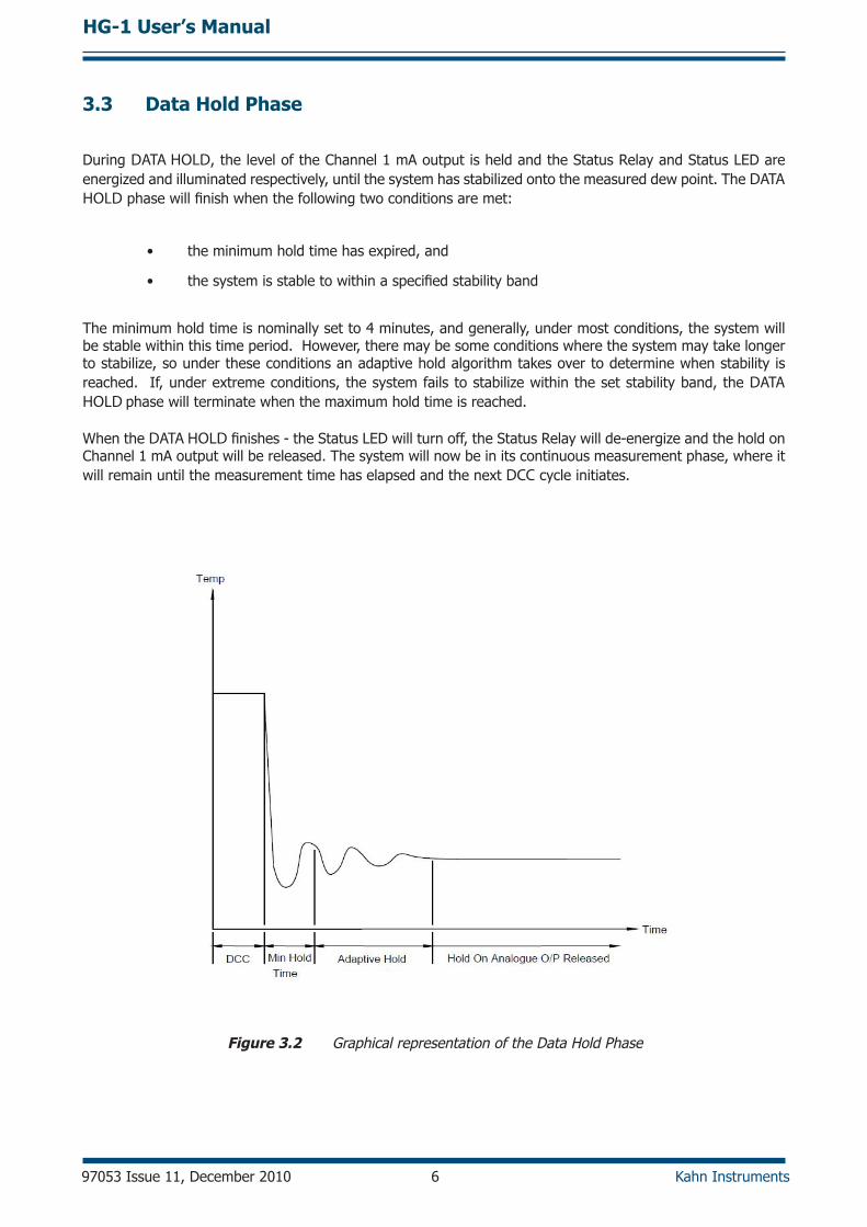
During DATA HOLD, the level of the Channel 1 mA output is held and the Status Relay and Status LED are energized and illuminated respectively, until the system has stabilized onto the measured dew point. The DATA HOLD phase will finish when the following two conditions are met:
• the minimum hold time has expired, and
• the system is stable to within a specified stability band
The minimum hold time is nominally set to 4 minutes, and generally, under most conditions, the system will be stable within this time period. However, there may be some conditions where the system may take longer to stabilize, so under these conditions an adaptive hold algorithm takes over to determine when stability is reached. If, under extreme conditions, the system fails to stabilize within the set stability band, the DATA HOLD phase will terminate when the maximum hold time is reached.
When the DATA HOLD finishes - the Status LED will turn off, the Status Relay will de-energize and the hold on Channel 1 mA output will be released. The system will now be in its continuous measurement phase, where it will remain until the measurement time has elapsed and the next DCC cycle initiates.
Figure 3.2 Graphical representation of the Data Hold Phase

HG-1 User’s Manual
Kahn Instruments 7 97053 Issue 11, December 2010
3.4 Display Screens
Below is a description of the parameters and system status information shown on each screen.
Screen 1: Displays the status of the Optidew
It will show DCC, DATA HOLD, OPTICS ALARM or MEASURE according to the current status of the Optidew instrument.
Screen 2: Peltier power and the Mirror condition
Peltier power indicates how much the heat pump is depressing in order to measure the dew point. When the peltier power has a value of 100% and does not reduce over an extended period of time, it means that the heat pump is at maximum depression. In normal operation this indicates that the dew point is lower than the present mirror temperature and therefore cannot be measured. Reducing the sensor ambient temperature by use of additional cooling will increase the measurement range of the instrument in applications where the peltier power >95%.
Alongside the peltier power value is an indicator that shows the control stability. When this indicator shows CNTRL, it indicates the system is controlling the mirror temperature on the dew point. COOL indicates the system is depressing the heat pump in order to form dew on the mirror surface. HEAT indicates a rapid increase in dew-point level, whereby the system needs to increase the temperature of the mirror surface to read this new dew-point value.
The Mirror condition indicates the amount of signal received back from the mirror which includes both the level of moisture and contamination on the mirror surface. In DCC mode this display will only show the amount of mirror contamination and, if greater than 80% after a DCC, will initiate an optics alarm condition.
Screen 3: Humidity in %RH and ambient temperature
Screen 4: Humidity in dew-point and ambient temperature
Screen 5: Humidity in gkg-1 and ambient temperature
Screen 6: Humidity in gm-3 and ambient temperature
Screen 7: The first line in this screen displays ∆ (t – tdp). This is the difference between ambient temperature and dew point. Note that this parameter will be equal to 0 if the dew point is higher than the ambient temperature (e.g. during a DCC cycle). The second line displays the ambient temperature.
Screen 8: The first line displays aW, which is equivalent to RH/100. The second line displays ambient temperature.

HG-1 User’s Manual
97053 Issue 11, December 2010 8 Kahn Instruments
Figure 3.3 Optidew Display Screens and Navigation

HG-1 User’s Manual
Kahn Instruments 9 97053 Issue 11, December 2010
3.5 Operating ProcedureThe procedure is as follows:
1. Switch the Gas Supply Selection Valve to either internal/external supply.
2. Switch on the power to the Humidity Calibrator. The Optidew instrument will enter DCC mode.
3. When power is applied the display will initially show test characters for approximately 0.5 seconds, after which the start-up banner will be displayed for approximately 7 seconds. The instrument will start up in LOCAL mode.
4. After the start-up banner has expired, the display will show screen 1. This displays the status of the Optidew Instrument. To scroll to screen 2, press and release the display control button. It is not possible to view any other screens until the DATA HOLD period is complete. NOTE: There may be a small delay before the display changes to the next screen; this is normal. After the DATA HOLD period has finished, screen 3 will appear. All eight screens can now be accessed by depressing the display control button.
5. Using the ‘Wet Flow’ and ‘Dry Flow’ metering valve and flowmeters set the humidity/dew-point temperature required. The following table shows the approximate flowrate settings required for generating various humidities/dew-point temperatures. If a sequence of humidities/dew points are required, it is important to start at the driest and select progressively through the range, always moving from dry to wet. This will drastically reduce the time taken for the generator to stablize at each point. Allow sufficient time for the instrument to thermally stabilize before monitoring humidity/dew-point readings.
Required Relative Humidity (%)
Required Dew Point (ºC)
Dry Flow Flowrate (l/min)
Wet Flow Flowrate (l/min)
10 -10 2.5 0.2
21 0 2.5 0.6
45 10 1.5 1.2
60 15 0.7 1.3
90 20 0 1.5
NOTE: These settings are only intended as a guide. The user will have to “fine tune” each setting for accurate humidities/dew points. These settings are calculated at an operating temperature of 23 °C. Therefore, if the operating temperature changes or the efficiency of the gas drying unit deteriorates then these settings will not be accurate.
Table 3.1 Guide to setting flowrates for required RH or dew point
6. When the dry gas supply from the gas drying unit deteriorates the Dry Flow setting will have to be increased and the Wet Flow setting decreased to compensate for the wetter supply gas. The compensation required will be greater at the lower humidities and eventually it will be impossible to generate the lower humidities. At this point the gas drying unit will need replacing/regenerating.
7. If the external dry compressed air supply is used the Dry Flow setting will have to be decreased and the Wet Flow setting increased to compensate for the dryer air supply.
8. Prior to shut-down, always return the calibrator to the ‘Full Dry’ (<10% RH) setting and allow the generator to run for several minutes to purge out the moisture in the system.

HG-1 User’s Manual
97053 Issue 11, December 2010 10 Kahn Instruments
4 MAINTENANCE
Routine maintenance of the Kahn Humidity Calibrator is limited to the following tasks:
• Re-Filling the Saturator System
• Gas Drying Unit Replacement
• Cleaning the Optidew Cooled Mirror Sensor
• Re-calibration of the Humidity Calibrator
4.1 Re-Filling the Saturator SystemThe frequency of re-filling the saturator system is dependent on the humidities being generated. High humidities will consume far more water than low humidities. The efficiency of the saturator system will reduce if the level of water is allowed to reduce. Kahn Instruments recommends that the saturator level is checked prior to use on a daily basis.Fill the saturator system following the steps below:
1. Disconnect the power supply to the calibrator.
2. Carefully unscrew and remove the filling port knurled nut and red plastic cap located on the rear panel of the unit.
3. Fill the saturator with clean distilled water to a level (viewed through the rear panel). The water level is not critical but should be kept above the minimum level and below the maximum level.
4. Replace the filling port red plastic cap and knurled nut and resume normal operation.
4.2 Gas Drying Unit Replacement
The calibrator is fitted with a desiccant dryer column to dry the air supply drawn from ambient. It is accessible from the rear panel of the unit.
The frequency of desiccant/dryer unit replacement is dependent upon the length of time in operation. Typically the gas drying unit can continually generate low humidities for a minimum period of 24 hours before replacement is required.
The desiccant provides an indication of its condition by a change in color: - blue represents a dry active condition whereas a deep pink represents a wet exhausted condition.
Kahn Instruments recommends initially that the gas drying unit be examined on a daily basis, and then depending on the condition, increase/decrease the maintenance period accordingly. Replacement Gas Drying Unit type - Aldrich type Z11287-9.
To replace the gas drying unit follow the steps below:
1. Disconnect the power supply to the calibrator and remove the rear panel.
2. Locate and release the gas drying unit from its retaining clips and remove the tubing from the gas ports at each end of the unit. Regenerate the desiccant or replace with a new/regenerated gas drying unit.
3. To regenerate the desiccant, remove it from the acrylic column and spread evenly on a tray. Heat for 1 hour at about 200°C. The desiccant should then be cooled in an air tight container before refilling back into the acrylic column. The felt filters should also be dried out at about 100°C for 30 minutes.
4. Re-assemble the gas drying unit into the calibrator and replace the rear panel and resume normal operation.

HG-1 User’s Manual
Kahn Instruments 11 97053 Issue 11, December 2010
4.3 Cleaning the Cooled Mirror Sensor
Throughout the life of the Optidew Cooled Mirror Sensor, periodic cleaning of the mirror surface and optics window may be required, depending upon operational conditions and exposure of the sensor to contamination.
Sensor cleaning is mandatory if the instrument indicates an optics fault. The cleaning procedure is as follows:
1. Switch the instrument off, or, if it is required to leave it on, a DCC cycle must be performed. Remove the test chamber cover.
2. Clean the mirror surface and optics window with a cotton bud soaked in distilled water. If the sensor has been exposed to oil based contamination then use one of the following solvents: methanol, ethanol, or isopropyl alcohol.
3. When cleaning is complete, replace the test chamber cover and switch the instrument on if necessary and observe the mirror contamination value during the DCC phase. If this value is not 0%, then remove the lid of the case and adjust the potentiometer until this value is reached, ensuring that the adjustments are made ONLY during the DCC phase. If this value is under-range the display will flash 0%, indicating that a positive adjustment is required.
NOTE: There will be a delay of approximately 5 seconds between the actual adjustment and the displayed value changing.
NOTE: If the mirror contamination value displays ‘low’ next to 0% (on display), or flashes 0% (through PC interface), this indicates that the value is below 0%, and needs positive adjustment.
Potentiometer
Front Panel
DesiccantColumn
Chamber
Saturator
Display
Figure 4.1 Potentiometer Location
4.4 Re-Calibration of the Humidity Calibrator
The Optidew is inherently drift free by design. However, as with any high quality measuring instrument, regular re-calibrations against standards are recommended.
This work can only be done by exposure of the Optidew Cooled Mirror Sensor to sample gases of known moisture content using calibrated test equipment traceable to national standards.
Kahn Instruments recommends that the Optidew Dew-Point Transmitter is re-calibrated on an annual basis to insure its accuracy.
HG-1 User’s Manual
97053 Issue 11, December 2010 12 Kahn Instruments
5 APPLICATION SOFTWARE
The application software is an interface to the Optidew that provides a display of the measured and calculated parameters, system status, charting and logging, statistical information and a facility to view and change the system parameters.
5.1 Virtual Hygrometer
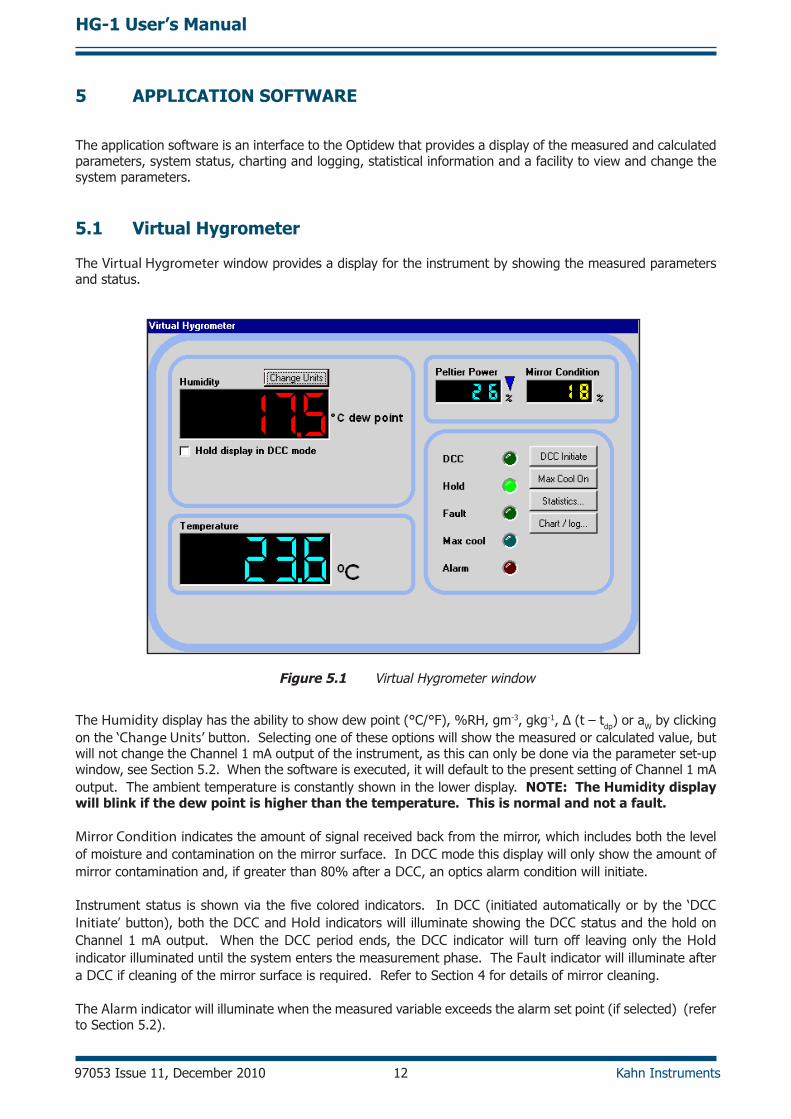
The Virtual Hygrometer window provides a display for the instrument by showing the measured parameters and status.
Figure 5.1 Virtual Hygrometer window
The Humidity display has the ability to show dew point (°C/°F), %RH, gm-3, gkg-1, ∆ (t – tdp) or aW by clicking on the ‘Change Units’ button. Selecting one of these options will show the measured or calculated value, but will not change the Channel 1 mA output of the instrument, as this can only be done via the parameter set-up window, see Section 5.2. When the software is executed, it will default to the present setting of Channel 1 mA output. The ambient temperature is constantly shown in the lower display. NOTE: The Humidity display will blink if the dew point is higher than the temperature. This is normal and not a fault.
Mirror Condition indicates the amount of signal received back from the mirror, which includes both the level of moisture and contamination on the mirror surface. In DCC mode this display will only show the amount of mirror contamination and, if greater than 80% after a DCC, an optics alarm condition will initiate.
Instrument status is shown via the five colored indicators. In DCC (initiated automatically or by the ‘DCC Initiate’ button), both the DCC and Hold indicators will illuminate showing the DCC status and the hold on Channel 1 mA output. When the DCC period ends, the DCC indicator will turn off leaving only the Hold indicator illuminated until the system enters the measurement phase. The Fault indicator will illuminate after a DCC if cleaning of the mirror surface is required. Refer to Section 4 for details of mirror cleaning.
The Alarm indicator will illuminate when the measured variable exceeds the alarm set point (if selected) (refer to Section 5.2).

HG-1 User’s Manual
Kahn Instruments 13 97053 Issue 11, December 2010
Max Cool can be initiated by the ‘Max Cool On’ button. Once initiated, the Max Cool indicator will illuminate and the system will drive the heat pump into maximum depression. This feature can be used to ascertain if the measured dew point is within the measurement capability of the instrument.
Clicking on the ‘Statistics’ button allows maximum, minimum and average values of the measured parameters to be viewed. See Section 5.4.
Charting and logging of the measured values can be initiated by clicking on the ‘Chart/log’ button. See Section 5.3. The ‘Hold display in DCC mode’ check box stops the system from updating the display during DCC, when enabled. The display is held when DCC is initiated and is not updated until both DCC and Hold periods have expired.
5.2 Parameter Setup
The Parameter Setup window allows the setting and ranging of Channel 1 and 2 mA outputs, the duration for DCC, Measurement and Hold, and the values for atmospheric pressure and alarm set points.
Figure 5.2 Parameter Setup window
The Display Units and Channel 1 mA Output are selected by clicking the left hand mouse button in the relevant box. This will change the settings of both the instrument and the virtual hygrometer window. Changing the mA outputs from 4-20 mA to 0-20 mA & vice versa will change both Channel 1 & Channel 2 mA outputs.

HG-1 User’s Manual
97053 Issue 11, December 2010 14 Kahn Instruments
The maximum and minimum values of Channel 1 and Channel 2 are –200 to +1000 respectively, therefore allowing the range of the outputs to be anywhere between these limits. The values for Max and Min must be integer values with a difference between them of at least 1°C/F.
If Channel 1 is to be set for % RH, gm-3, gkg-1 or ∆ (t – tdp), then the minimum value of Channel 1 Min should be 0, as a negative value for these parameters is not possible.
The pressure value is used to correct gm-3 and gkg-1 for atmospheric pressure. By entering the atmospheric pressure the display and Channel 1 mA output (if either gm-3 or gkg-1 is selected) will both be corrected accordingly.
The Alarm can be set to OFF or set to be active on any of the process variables i.e. dew point, ambient temperature, temperature difference, % RH, gm-3 or gkg-1 as shown above. The set point needs to be an integer value between –200 and +1000, although negative set points are only valid for dew point and ambient temperature. If the process variable exceeds the set point, the Alarm indicator on the virtual hygrometer will illuminate and the Optics Fault/Alarm relay will change state.
To change any of the values, enter the required value and click on the return key. The background of the text box will change to yellow to indicate that the change is taking place. When confirmation has been received that the instrument has accepted the change, the background will change back to green.
NOTE: When the Parameter Setup window is open, the values in the Virtual Hygrometer window are frozen. The Parameter Setup window needs to be closed for the software to resume normal display mode.

HG-1 User’s Manual
Kahn Instruments 15 97053 Issue 11, December 2010
5.3 Charting and Logging
Clicking on the ‘Chart/log’ button in the Virtual Hygrometer window brings up the Chart / log control panel window.
Figure 5.3 Chart/Log Control Panel window
The chart, in its default configuration, displays dew point, temperature and % RH. However, gm-3, gkg-1 and ∆(t – tdp), can be added by clicking in the appropriate check box. Within the Global section, you can select the charting and logging interval from a minimum of 5 seconds to a maximum of 1 hour. It offers the facility to log the temperature of the mirror while in DCC and Hold, or hold the measured value while in these modes and chart the held data values accordingly.
To log the measured and calculated humidity values to a data file for further analysis, click on the check box in the Logging section and specify a file name by clicking on the ‘Browse’ button. If a log file is not required simply uncheck the box.
To Run, Pause and Stop the charting and logging facility, use the chart control buttons accordingly.

HG-1 User’s Manual
97053 Issue 11, December 2010 16 Kahn Instruments
Clicking on the ‘Run’ button will bring up the chart as shown below. The chart shows the measured and calculated humidity values selected in the Chart section, with an assigned identifiable color for each value. It is possible to scale, zoom and scroll both X and Y axis of the chart by using the controls in the Chart Settings window, which can be activated by clicking on the ‘Chart Settings’ button in the Chart window.
Figure 5.4 Chart window
The X & Y axes can be individually scaled. The X-axis can be scaled by using the ZoomX feature in the Chart mode section, while the Y-axis can be scaled by changing the min and max values, or selecting a parameter in the Auto-scale list, which scales the Y-axis to the actual values of the parameter.
There are a number of modes associated with the chart, which can be selected from the Chart mode list; Plot, Scroll (X, Y, & XY), Cursor, Zoom (X, Y, & XY) and Zoom Box. In order to use the scrolling and zooming modes, make your selection and click the left mouse button on the chart itself, moving the mouse across the chart accordingly with the left mouse button held down. This will zoom or scroll the chart accordingly.
Individual data points can be selected from the chart by using the cursor mode. Select the parameter in question by clicking on a legend on the right hand side of the chart (°C dew point is shown as selected above) and moving the cursor to the point of interest - the actual value with its time stamp will be displayed above the chart.

HG-1 User’s Manual
Kahn Instruments 17 97053 Issue 11, December 2010
5.4 Statistics
Clicking on the ‘Statistics’ button on the Virtual Hygrometer window will display the Basic statistics window as shown below:
Figure 5.5 Basic Statistics window
This window shows the maximum, minimum and average of each parameter since the program began taking readings from the instrument, or since the re-set button was pressed.
5.5 Control Parameters
The control parameters (protected by a password) should only be amended by trained personnel in order to adjust the system for operation in extreme conditions. Contact
a Kahn Technical Representative for details.

HG-1 User’s Manual
97053 Issue 11, December 2010 18 Kahn Instruments
5.6 Calibration Correction
Every Optidew is delivered with a Calibration Certificate detailing the deviation at each measurement point from a known reference value. Data provided on the Calibration Certificate is normally arranged as shown in the following extracts:
Extract from a UKAS Calibration Certificate:
GeneratedDew point
°C
Test Hygrometer
Dew-pointTemperature
°C
Sensor Temperature
°C
CorrectionRequired
°C
ExpandedUncertainty
°C-39.89 -40.11 -20 +0.22 ±0.26
-20.10 -20.31 0 +0.21 ±0.22
0.39 0.20 21 +0.19 ±0.18
Extract from a Standard Calibration Certificate:
Generated Dew point
°C
InstrumentDisplay °C
-40.1 -40.2
-20.1 -20.1
0.2 0.1
Figure 5.6 Extracts from Calibration Certificates
From time to time the Optidew may be calibrated by an external calibration agency, where similar data will be provided.

HG-1 User’s Manual
Kahn Instruments 19 97053 Issue 11, December 2010
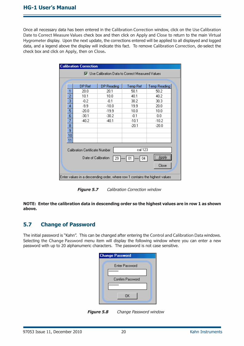
The Calibration Correction window is a utility that allows an authorized user to input calibration information in order to effect a real-time correction of the displayed, charted and logged data within the Opti-Soft application software.
Data for dew-point temperature and ambient temperature, both in units of °C, may be entered for correction purposes, along with the original Calibration Certificate reference number and date of calibration, providing full traceability of data. Once the correction data has been applied, by clicking on the check box, the main Virtual Hygrometer window will indicate that corrected data is being displayed and will show the Calibration Certificate number and date. This information is also saved to the Log file for data export.
Figure 5.7 on the next page shows the Calibration Correction window. Four sets of data may be entered:
DP Ref Dew-point data for the reference hygrometer (sometimes called the actual dew point or the standard)
DP Reading Measured dew-point value of the Optidew under test
Temp Ref Temperature data from the reference thermometer
Temp Reading This is the measured temperature value of the Optidew under test
Data can be entered for between 3 and 11 different dew-point and temperature calibration points. If no data is inserted, no calibration correction is possible. Data should be entered with the highest dew-point and temperature values at the top of the page, in descending value order to the bottom. If out-of-sequence data or spurious characters are entered, the software will raise a warning message and bad data must be re-entered.
The Calibration Certificate Number field is an optional entry field and is alphanumeric. Any information entered into this field will be displayed on the main Virtual Hygrometer window when calibration correction is enabled. In addition it will be saved to the Log file. Similarly, the date of calibration may be entered for display and logging when correction is enabled.
HG-1 User’s Manual
97053 Issue 11, December 2010 20 Kahn Instruments
Once all necessary data has been entered in the Calibration Correction window, click on the Use Calibration Date to Correct Measure Values check box and then click on Apply and Close to return to the main Virtual Hygrometer display. Upon the next update, the corrections entered will be applied to all displayed and logged data, and a legend above the display will indicate this fact. To remove Calibration Correction, de-select the check box and click on Apply, then on Close.
Figure 5.7 Calibration Correction window
NOTE: Enter the calibration data in descending order so the highest values are in row 1 as shown above.
5.7 Change of Password
The initial password is “Kahn”. This can be changed after entering the Control and Calibration Data windows. Selecting the Change Password menu item will display the following window where you can enter a new password with up to 20 alphanumeric characters. The password is not case sensitive.
Figure 5.8 Change Password window

HG-1 User’s Manual
Kahn Instruments 21 97053 Issue 11, December 2010
Appendix A
Technical Specifications
HG-1 User’s Manual
97053 Issue 11, December 2010 22 Kahn Instruments
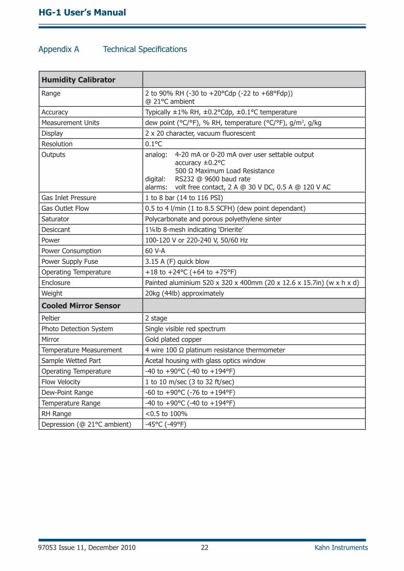
Appendix A Technical Specifications
Humidity Calibrator
Range 2 to 90% RH (-30 to +20°Cdp (-22 to +68°Fdp)) @ 21°C ambient
Accuracy Typically ±1% RH, ±0.2°Cdp, ±0.1°C temperature
Measurement Units dew point (°C/°F), % RH, temperature (°C/°F), g/m3, g/kg
Display 2 x 20 character, vacuum fluorescent
Resolution 0.1°C
Outputs analog: 4-20 mA or 0-20 mA over user settable output accuracy ±0.2°C 500 Ω Maximum Load Resistancedigital: RS232 @ 9600 baud ratealarms: volt free contact, 2 A @ 30 V DC, 0.5 A @ 120 V AC
Gas Inlet Pressure 1 to 8 bar (14 to 116 PSI)
Gas Outlet Flow 0.5 to 4 l/min (1 to 8.5 SCFH) (dew point dependant)
Saturator Polycarbonate and porous polyethylene sinter
Desiccant 1¼lb 8-mesh indicating ‘Drierite’
Power 100-120 V or 220-240 V, 50/60 Hz
Power Consumption 60 V-A
Power Supply Fuse 3.15 A (F) quick blow
Operating Temperature +18 to +24°C (+64 to +75°F)
Enclosure Painted aluminium 520 x 320 x 400mm (20 x 12.6 x 15.7in) (w x h x d)
Weight 20kg (44lb) approximately
Cooled Mirror Sensor
Peltier 2 stage
Photo Detection System Single visible red spectrum
Mirror Gold plated copper
Temperature Measurement 4 wire 100 Ω platinum resistance thermometer
Sample Wetted Part Acetal housing with glass optics window
Operating Temperature -40 to +90°C (-40 to +194°F)
Flow Velocity 1 to 10 m/sec (3 to 32 ft/sec)
Dew-Point Range -60 to +90°C (-76 to +194°F)
Temperature Range -40 to +90°C (-40 to +194°F)
RH Range <0.5 to 100%
Depression (@ 21°C ambient) -45°C (-49°F)
HG-1 User’s Manual
Kahn Instruments 23 97053 Issue 11, December 2010
Satu
rato
rFi
lling
Por
t
REA
R VI
EW
Gas
Dry
er
Uni
t
Vent
ilatio
nFa
ns
Satu
rato
r Bo
ttle
Rem
ovab
leCl
ear
Pane
l
305mm (12”)
Hum
idity
Dis
play
Out
puts
Conn
ecto
r
RS2
32 C
OM
MS
Conn
ecto
r
Pow
er O
N/O
FFSw
itch
Pow
er S
uppl
yCo
nnec
tion
Exte
rnal
Gas
Inle
t
Air
Supp
lySe
lect
ion
Valv
e
Wet
Flo
wFl
owm
eter
and
Valv
e
Dry
Flo
wFl
owm
eter
and
Valv
e
Dis
play
Con
trol
Switc
h
400mm (15.75”)
520m
m (2
0.47
”)
Rece
ssed
Car
ryH
andl
es
Opt
idew
Tr
ansm
itter
Opt
idew
Sen
sor
and
Tem
pera
ture
Prob
e
Calib
ratio
n Te
st C
ham
ber
Plas
tic R
emov
able
Cov
er(U
ser
Conf
igur
able
Spa
ceis
170
x 1
00 x
100
mm
)
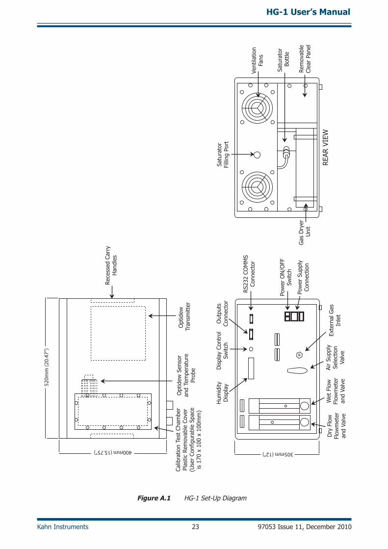
Figure A.1 HG-1 Set-Up Diagram

HG-1 User’s Manual
97053 Issue 11, December 2010 24 Kahn Instruments
SATU
RAT
OR
0.1
- 1.
5 L/
MIN
WET
FLO
WM
ETER
AND
VAL
VE
0.2
- 2.
5 L/
MIN
DRY
FLO
WM
ETER
AND
VAL
VE
SWIT
CHIN
GBA
LL V
ALVE
PRES
SURE
REG
ULA
TOR
GAS
DRY
EROU
TLET
PRES
SURE
PRES
ET T
O 1
0 PS
IG
CALI
BRAT
ION
TEST
CH
AMBE
R
TEM
PERAT
URE
PRO
BEO
PTID
EWSE
NSO
R
VEN
T
OPT
IDEW
TRAN
SMIT
TER
COM
PRES
SED
AIR
(8 B
ARG
MAX
)
AMBI
ENT
AIR
PUM
P
Figure A.2 HG-1 Flow Diagram