hi 400 inverter
TRANSCRIPT

HI400
Owner’s Guide

About XantrexXantrex Technology develops, manufactures, and markets advanced power electronic products. The company’s products convert raw electrical power from any source into high-quality power required by electronic and electrical equipment.
TrademarkXantrex is a registered trademark of Xantrex Technology Inc.Other trademarks, registered trademarks, and product names are the property of their respective owners and are used herein for identification purposes only.
Notice of CopyrightHI400 Owner’s Guide © January 2002 Xantrex International. All rights reserved.
DisclaimerUNLESS SPECIFICALLY AGREED TO IN WRITING, XANTREX TECHNOLOGY INC. (“XANTREX”):(a) MAKES NO WARRANTY AS TO THE ACCURACY, SUFFICIENCY OR SUITABILITY OF ANY TECHNICAL OR OTHER INFORMATION PROVIDED IN ITS MANUALS OR OTHER DOCUMENTATION.(b) ASSUMES NO RESPONSIBILITY OR LIABILITY FOR LOSS OR DAMAGE, WHETHER DIRECT, INDIRECT, CONSEQUENTIAL OR INCIDENTAL, WHICH MIGHT ARISE OUT OF THE USE OF SUCH INFORMATION. THE USE OF ANY SUCH INFORMATION WILL BE ENTIRELY AT THE USER’S RISK.
Date and RevisionJanuary 2002, Revision 2
Part Number445-0151-01-01
Contact Information
Web: www.xantrex.comEmail: [email protected]: 1-800-446-6180Fax: 1-360-925-5143

Contents
Important safety informationGeneral precautions - - - - - - - - - - - - - - - - - - - - - - - - - - - - - - - - vExplosive gas precautions - - - - - - - - - - - - - - - - - - - - - - - - - - - viPrecautions when working with batteries - - - - - - - - - - - - - - - - - viiPrecautions for using rechargeable appliances - - - - - - - - - - - - viii
1 Introduction
Introduction - - - - - - - - - - - - - - - - - - - - - - - - - - - - - - - - - - - - - 2HI400 features - - - - - - - - - - - - - - - - - - - - - - - - - - - - - - - - - - - 4Materials list - - - - - - - - - - - - - - - - - - - - - - - - - - - - - - - - - - - - - 6
2 Installation
Preparing for installation- - - - - - - - - - - - - - - - - - - - - - - - - - - - - 8Installation codes - - - - - - - - - - - - - - - - - - - - - - - - - - - - - - - - 8Installation tools and materials - - - - - - - - - - - - - - - - - - - - - - - 9Installation features - - - - - - - - - - - - - - - - - - - - - - - - - - - - - - 10
Installing the HI400 - - - - - - - - - - - - - - - - - - - - - - - - - - - - - - - 11Overview- - - - - - - - - - - - - - - - - - - - - - - - - - - - - - - - - - - - - 11Designing your installation - - - - - - - - - - - - - - - - - - - - - - - - - 11Choosing a location- - - - - - - - - - - - - - - - - - - - - - - - - - - - - - 15Mounting your inverter - - - - - - - - - - - - - - - - - - - - - - - - - - - 16Permanently connecting (hardwiring) the AC output- - - - - - - - 17Installing the ignition lockout wiring - - - - - - - - - - - - - - - - - - 18Connecting the DC cables - - - - - - - - - - - - - - - - - - - - - - - - - 19Connecting the battery to the DC input - - - - - - - - - - - - - - - - - 20Connecting the DC ground - - - - - - - - - - - - - - - - - - - - - - - - - 21
i

Contents
Connecting the AC input cord - - - - - - - - - - - - - - - - - - - - - - - 22Checks prior to initial power-up - - - - - - - - - - - - - - - - - - - - - 23Starting up and testing your installation - - - - - - - - - - - - - - - - 23
3 Operation
Operation features - - - - - - - - - - - - - - - - - - - - - - - - - - - - - - - - 26Inverter on and off - - - - - - - - - - - - - - - - - - - - - - - - - - - - - - 26Ground fault circuit interrupter (GFCI) protection - - - - - - - - - 26Alternate AC source - - - - - - - - - - - - - - - - - - - - - - - - - - - - - 27Ignition lockout - - - - - - - - - - - - - - - - - - - - - - - - - - - - - - - - 27Low battery condition - - - - - - - - - - - - - - - - - - - - - - - - - - - - 27
Inverter loads - - - - - - - - - - - - - - - - - - - - - - - - - - - - - - - - - - - 28Operating several loads at once - - - - - - - - - - - - - - - - - - - - - - 28Problem loads- - - - - - - - - - - - - - - - - - - - - - - - - - - - - - - - - - 28Turning the inverter off between charges - - - - - - - - - - - - - - - 29Battery charging frequency- - - - - - - - - - - - - - - - - - - - - - - - - 29
4 Maintenance and Troubleshooting
Maintenance - - - - - - - - - - - - - - - - - - - - - - - - - - - - - - - - - - - - 32Troubleshooting - - - - - - - - - - - - - - - - - - - - - - - - - - - - - - - - - 32
Common problems - - - - - - - - - - - - - - - - - - - - - - - - - - - - - - 32Buzz in audio equipment - - - - - - - - - - - - - - - - - - - - - - - - - - 32Television interference- - - - - - - - - - - - - - - - - - - - - - - - - - - - 32
Troubleshooting reference- - - - - - - - - - - - - - - - - - - - - - - - - - - 33
A Specifications
Electrical - - - - - - - - - - - - - - - - - - - - - - - - - - - - - - - - - - - - - - 36Physical - - - - - - - - - - - - - - - - - - - - - - - - - - - - - - - - - - - - - - - 36
B Battery Types and Sizes
Battery types- - - - - - - - - - - - - - - - - - - - - - - - - - - - - - - - - - - - 38Automotive starting batteries - - - - - - - - - - - - - - - - - - - - - - - 38Deep-cycle lead-acid batteries- - - - - - - - - - - - - - - - - - - - - - - 38
Battery size- - - - - - - - - - - - - - - - - - - - - - - - - - - - - - - - - - - - - 39
ii
Contents
Estimating battery requirements - - - - - - - - - - - - - - - - - - - - - - - 40Battery sizing example- - - - - - - - - - - - - - - - - - - - - - - - - - - - 41Battery sizing worksheet - - - - - - - - - - - - - - - - - - - - - - - - - - 42
Using multiple batteries - - - - - - - - - - - - - - - - - - - - - - - - - - - - 43Two batteries connected in parallel - - - - - - - - - - - - - - - - - - - 43Two separate battery banks- - - - - - - - - - - - - - - - - - - - - - - - - 43
Battery tips - - - - - - - - - - - - - - - - - - - - - - - - - - - - - - - - - - - - - 44
C Warranty and Product Information
Warranty information - - - - - - - - - - - - - - - - - - - - - - - - - - - - - - 48Returning a product - - - - - - - - - - - - - - - - - - - - - - - - - - - - - - - 49Out-of-warranty service - - - - - - - - - - - - - - - - - - - - - - - - - - - - 50Contacting Xantrex Customer Service- - - - - - - - - - - - - - - - - - - 51Other Xantrex products- - - - - - - - - - - - - - - - - - - - - - - - - - - - - 51
Index - - - - - - - - - - - - - - - - - - - - - - - - - - - - - - - - - - 53
iii

iv

Important safety information
General precautions1. Before installing and using the inverter, read all
appropriate sections of this guide and any cautionary markings on the inverter and batteries.
2. Do not operate the inverter if it has received a sharp blow, been dropped, or otherwise damaged. If the unit is damaged, see “Service during warranty” on page 48 and “Returning a product” on page 49.
3. Do not disassemble the inverter; it contains no user serviceable parts. Attempting to service the unit yourself could cause electrical shock or fire. Internal capacitors remain charged after all power is disconnected. See “Warranty information” on page 48 for instructions on obtaining service.
4. To reduce the risk of electrical shock, disconnect both AC and DC power from the inverter before working on any circuits connected to the inverter. Turning off the front panel On/Off Switch will not reduce this risk.
5. Protect the inverter from rain, snow, spray, and bilge water.
6. To reduce the risk of overheating or fire, keep the ventilation openings clear, and do not install the inverter in a zero-clearance compartment.
Important: Before installing and using your HI400 Inverter, be sure to read and save these safety instructions.
v
Explosive gas precautions
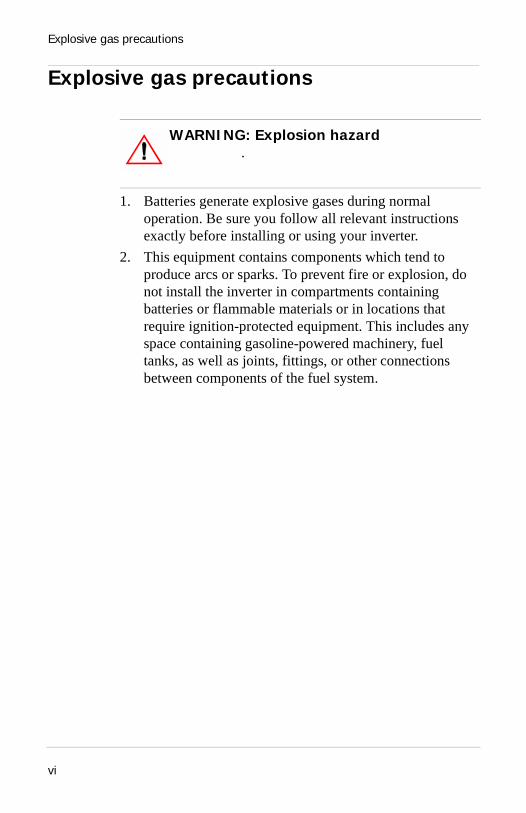
Explosive gas precautions
1. Batteries generate explosive gases during normal operation. Be sure you follow all relevant instructions exactly before installing or using your inverter.
2. This equipment contains components which tend to produce arcs or sparks. To prevent fire or explosion, do not install the inverter in compartments containing batteries or flammable materials or in locations that require ignition-protected equipment. This includes any space containing gasoline-powered machinery, fuel tanks, as well as joints, fittings, or other connections between components of the fuel system.
WARNING: Explosion hazard.
vi

Precautions when working with batteries
Precautions when working with batteries
1. Follow all instructions published by the battery manufacturer and the manufacturer of the equipment in which the battery is installed.
2. Make sure the area around the battery is well ventilated.3. Never smoke or allow a spark or flame near the engine or
battery.4. Use caution to reduce the risk of dropping a metal tool on
the battery. It could spark or short circuit the battery or other electrical parts and could cause an explosion.
5. Remove metal items like rings, bracelets, and watches when working with lead-acid batteries. These batteries produce a short-circuit current high enough to weld a ring or the like to metal and cause a severe burn.
6. If you need to remove a battery, always remove the positive terminal from the battery first. Make sure all accessories are off so you don’t cause an arc.
WARNING: Explosion and fire hazards
vii

Precautions for using rechargeable appliances
Precautions for using rechargeable appliances
Most rechargeable battery-operated equipment uses a separate charger or transformer that is plugged into an AC receptacle and produces a low voltage charging out.
Some chargers for rechargeable batteries can be damaged if connected to the HI400 Inverter.
Do not use the following with the HI400 Inverter:
• Small battery-operated appliances like flashlights, razors, and night lights that can be plugged directly into an AC receptacle to recharge.
• Some chargers for battery packs used in hand power tools. These affected chargers display a warning label stating that dangerous voltages are present at the battery terminals.
viii

Introduction
Chapter 1 “Introduction” describes the main operating features of the HI400 Inverter.
1

Introduction
Introduction
The HI400 Inverter is a modified sine wave (MSW) inverter providing power for a variety of AC loads, such as TVs, VCRs, laptops, camcorders and other small AC devices. They are CSA certified for use in recreational vehicles.
The HI400 is available in two versions:• “HI400 with hardwire” is designed for permanent
hardwired installation.• “HI400 with hardwire and GFCI outlet” has a GFCI
receptable on the front and a hardwire compartment. It provides easy access for plugging a load directly into the output of the unit. The hardwire compartment allows the unit to be installed permanently.
HI400 offers the following inverter features:• Ability to run many of the entertainment loads that you
use at home.You can operate TVs, stereos, VCRs, computers and even small battery chargers. You can run multiple loads up to 400 watts in total.
• Surge capabilityHI400 will surge up to 550 watts peak.
• Low voltage shutdownThe inverter shuts off when your batteries discharge to less than 10 volts.When the battery voltage recharges to above 12.5 volts, the inverter automatically restarts. This feature prevents the inverter from draining the batteries if it is left on without a load.
• Ground fault circuit interrupter (GFCI)As well as providing for permanent hardwire installation, the GFCI model provides a receptacle for plugging in a load.
2

Introduction
This receptacle has a “ground fault circuit interrupter” to reduce shock hazards on loads connected to both the receptacle and hardwire outputs.
• Ignition lockoutIgnition lockout prevents the inverter from operating while the engine is running. It allows the user to turn the inverter on and off remotely.
• Transfer switchAutomatically connects the loads on the receptacle and hardwire outputs to the external AC source when one is available. Upon disconnection, or loss of the external AC source, the transfer switch automatically transfers the load circuits over to inverter power.
3
HI400 features
HI400 features
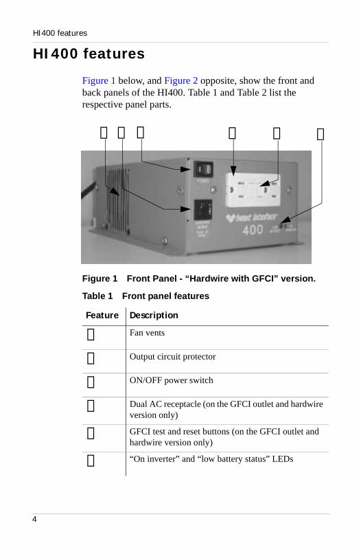
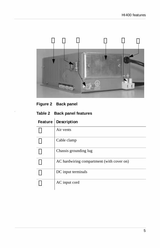
Figure 1 below, and Figure 2 opposite, show the front and back panels of the HI400. Table 1 and Table 2 list the respective panel parts.
Figure 1 Front Panel - “Hardwire with GFCI” version.
Table 1 Front panel features
Feature Description
➀ Fan vents
➁ Output circuit protector
➂ ON/OFF power switch
➃ Dual AC receptacle (on the GFCI outlet and hardwire version only)
➄ GFCI test and reset buttons (on the GFCI outlet and hardwire version only)
➅ “On inverter” and “low battery status” LEDs
➂ ➃ ➄ ➅➀ ➁
4
HI400 features
Figure 2 Back panelp
Table 2 Back panel features
Feature Description
➀ Air vents
➁ Cable clamp
➂ Chassis grounding lug
➃ AC hardwiring compartment (with cover on)
➄ DC input terminals
➅ AC input cord
➀ ➁ ➂ ➃ ➄ ➅
5

Materials list
Materials list
Your HI400 inverter package includes the items listed below:
❐ Inverter with hardwire (80-0401-12) or
Inverter with hardwire and GFCI outlet (80-0400-12)
❐ Owner’s Guide
6

Installation
Chapter 2 “Installation” provides complete information for installing the HI400 Inverter. Specifically, this section describes:• safety instructions and installation codes
that must be observed during installation.• installation tools and materials.• appropriate locations and environments
for mounting the inverter.• AC cabling, DC cabling, and ground
information.• detailed installation procedures.
7

Preparing for installation
Preparing for installation
Prior to beginning your installation, review the “Important Safety Instructions” on page v, and read the entire “Installation” section so you can plan your installation from beginning to end.
Installation codes
Applicable installation codes vary depending on the specific location and application of the installation. Some examples are:
• The U.S. National Electrical Code (NEC)• The Canadian Electrical Code (NEC)• NEC, Canadian Standards Association (CSA), and RV
Industry Association (RVIA) requirements for installation in RVs.
It is the installer’s responsibility to determine which codes apply, and to ensure that all applicable installation requirements are met.
WARNING: Electrical shock and fire hazardsXantrex recommends all wiring be done by qualified personnel. Disconnect all AC and DC power sources to prevent accidental shock. Disable and secure all AC and DC disconnect devices and automatic generator starting devices.It is the installer’s responsibility to ensure compliance with all applicable installation codes and regulations.
CAUTIONBe sure to read all instructions before installing and operating this inverter.
8
Preparing for installation
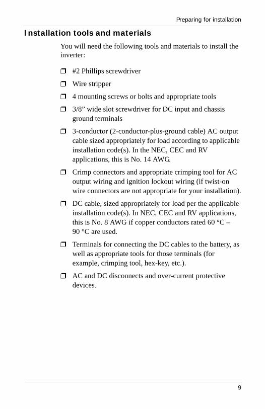
Installation tools and materials
You will need the following tools and materials to install the inverter:
❐ #2 Phillips screwdriver
❐ Wire stripper
❐ 4 mounting screws or bolts and appropriate tools
❐ 3/8” wide slot screwdriver for DC input and chassis ground terminals
❐ 3-conductor (2-conductor-plus-ground cable) AC output cable sized appropriately for load according to applicable installation code(s). In the NEC, CEC and RV applications, this is No. 14 AWG.
❐ Crimp connectors and appropriate crimping tool for AC output wiring and ignition lockout wiring (if twist-on wire connectors are not appropriate for your installation).
❐ DC cable, sized appropriately for load per the applicable installation code(s). In NEC, CEC and RV applications, this is No. 8 AWG if copper conductors rated 60 °C –90 °C are used.
❐ Terminals for connecting the DC cables to the battery, as well as appropriate tools for those terminals (for example, crimping tool, hex-key, etc.).
❐ AC and DC disconnects and over-current protective devices.
9

Preparing for installation
Installation features
Figure 3 and Table 3 below, list the installation features of your HI400 inverter.
Figure 3 Installation features: back view
Table 3 Installation features: back view
Feature Description
➀ DC input terminals
➁ Cable clamp
➂ Chassis grounding lug
➃ AC Hardwire compartment
➄ Ground screw for AC output ground
➅ Ignition lockout wire (red)
➆ AC output wiring (black, white)
➇ AC input cord
➈ Wire connectors (3)
➀
➇
➈
➆➁ ➂ ➃ ➅➄
10
Installing the HI400
Installing the HI400
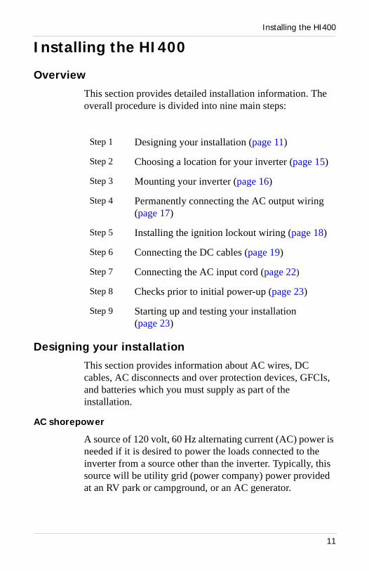
Overview
This section provides detailed installation information. The overall procedure is divided into nine main steps:
Designing your installation
This section provides information about AC wires, DC cables, AC disconnects and over protection devices, GFCIs, and batteries which you must supply as part of the installation.
AC shorepower
A source of 120 volt, 60 Hz alternating current (AC) power is needed if it is desired to power the loads connected to the inverter from a source other than the inverter. Typically, this source will be utility grid (power company) power provided at an RV park or campground, or an AC generator.
Step 1 Designing your installation (page 11)
Step 2 Choosing a location for your inverter (page 15)
Step 3 Mounting your inverter (page 16)
Step 4 Permanently connecting the AC output wiring (page 17)
Step 5 Installing the ignition lockout wiring (page 18)
Step 6 Connecting the DC cables (page 19)
Step 7 Connecting the AC input cord (page 22)
Step 8 Checks prior to initial power-up (page 23)
Step 9 Starting up and testing your installation (page 23)
11

Installing the HI400
AC disconnects and over-current protection devices
To meet electrical code requirements, you must provide the inverter with over-current protection (such as a circuit breaker or fuse) and a disconnect device as follows:
AC Input: The circuit breaker or fuse used to protect the HI400 inverter must be rated no more than 15 A and must be approved for use on 120 Vac branch circuits.
AC Output: The circuit breaker or fuse must be rated at no more than 15 A and must be approved for use on 120 Vac branch circuits.
Disconnect devices: Each system requires a method of disconnecting each AC circuit. If the over-current protection device is a circuit breaker, it will serve as a disconnect switch. If fuses are used, separate AC disconnect switches will be needed between the source of power and the fuses.
AC output wiring
The type and size of the wires between the inverter output and the loads varies with the installation type and applicable codes. For many RV applications, flexible multi-strand wire is required. Installation codes may specify solid or stranded, overall size of the conductors, and type and temperature rating of the insulation around the wire.
The AC output wiring must be sized to match the current rating of the circuit breaker or fuse you provide on AC output circuits. The size must be in accordance with the electrical codes or regulations applicable to your installation. In most NEC, CEC, and RV installations, the wire size will be required to be No. 14 AWG, 3-conductor (line and neutral, plus ground).
Note: Throughout this manual, the term “shorepower” refers to AC input power from a utility grid, generator, or other source.
12
Installing the HI400
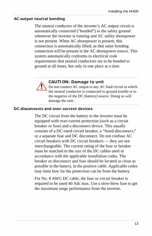
AC output neutral bonding
The neutral conductor of the inverter’s AC output circuit is automatically connected (“bonded”) to the safety ground whenever the inverter is running and AC utility shorepower is not present. When AC shorepower is present, this connection is automatically lifted, as that same bonding connection will be present in the AC shorepower source. This system automatically conforms to electrical code requirements that neutral conductors are to be bonded to ground at all times, but only in one place at a time.
DC disconnects and over-current devices
The DC circuit from the battery to the inverter must be equipped with over-current protection (such as a circuit breaker or fuse) and a disconnect device. This usually consists of a DC-rated circuit breaker, a “fused-disconnect,” or a separate fuse and DC disconnect. Do not confuse AC circuit breakers with DC circuit breakers — they are not interchangeable. The current rating of the fuse or breaker must be matched to the size of the DC cables used in accordance with the applicable installation codes. The breaker or disconnect and fuse should be located as close as possible to the battery, in the positive cable. Applicable codes may limit how far the protection can be from the battery.
For No. 8 AWG DC cable, the fuse or circuit breaker is required to be rated 40 Adc max. Use a slow-blow fuse to get the maximum surge performance from the inverter.
CAUTION: Damage to unitDo not connect AC output to any AC load circuit in which the neutral conductor is connected to ground (earth) or to the negative of the DC (battery) source. Doing so will damage the unit.
13
Installing the HI400
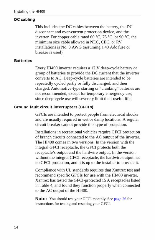
DC cabling
This includes the DC cables between the battery, the DC disconnect and over-current protection device, and the inverter. For copper cable rated 60 °C, 75 °C, or 90 °C, the minimum size cable allowed in NEC, CEC, or RV installations is No. 8 AWG (assuming a 40 Adc fuse or breaker is used).
Batteries
Every HI400 inverter requires a 12 V deep-cycle battery or group of batteries to provide the DC current that the inverter converts to AC. Deep-cycle batteries are intended to be repeatedly cycled partly or fully discharged, and then charged. Automotive-type starting or “cranking” batteries are not recommended, except for temporary emergency use, since deep-cycle use will severely limit their useful life.
Ground fault circuit interrupters (GFCIs)
GFCIs are intended to protect people from electrical shocks and are usually required in wet or damp locations. A regular circuit breaker cannot provide this type of protection.
Installations in recreational vehicles require GFCI protection of branch circuits connected to the AC output of the inverter. The HI400 comes in two versions. In the version with the integral GFCI receptacle, the GFCI protects both the receptacle’s output and the hardwire output. In the version without the integral GFCI receptacle, the hardwire output has no GFCI protection, and it is up to the installer to provide it.
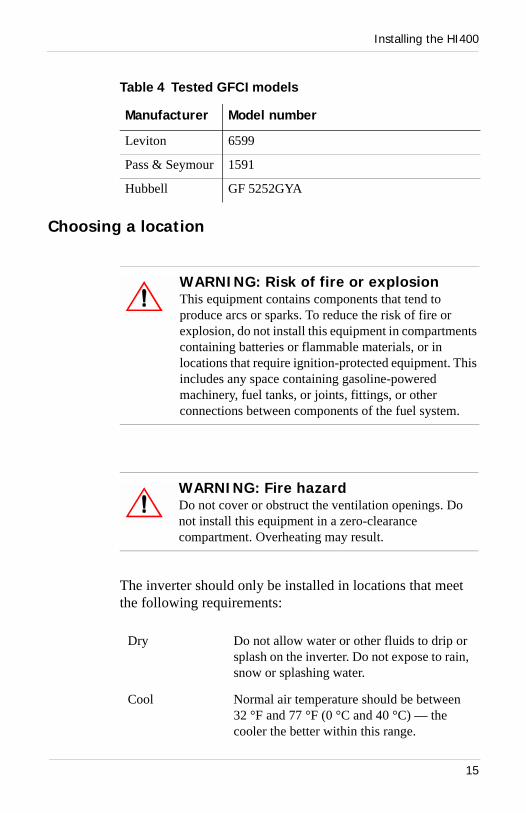
Compliance with UL standards requires that Xantrex test and recommend specific GFCIs for use with the HI400 inverter. Xantrex has tested the GFCI-protected 15 A receptacles listed in Table 4, and found they function properly when connected to the AC output of the HI400.
Note: You should test your GFCI monthly. See page 26 for instructions for testing and resetting your GFCI.
14
Installing the HI400
Choosing a location
The inverter should only be installed in locations that meet the following requirements:
Table 4 Tested GFCI models
Manufacturer Model number
Leviton 6599
Pass & Seymour 1591
Hubbell GF 5252GYA
WARNING: Risk of fire or explosionThis equipment contains components that tend to produce arcs or sparks. To reduce the risk of fire or explosion, do not install this equipment in compartments containing batteries or flammable materials, or in locations that require ignition-protected equipment. This includes any space containing gasoline-powered machinery, fuel tanks, or joints, fittings, or other connections between components of the fuel system.
WARNING: Fire hazardDo not cover or obstruct the ventilation openings. Do not install this equipment in a zero-clearance compartment. Overheating may result.
Dry Do not allow water or other fluids to drip or splash on the inverter. Do not expose to rain, snow or splashing water.
Cool Normal air temperature should be between 32 °F and 77 °F (0 °C and 40 °C) — the cooler the better within this range.
15
Installing the HI400
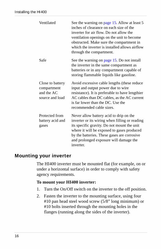
Mounting your inverter
The HI400 inverter must be mounted flat (for example, on or under a horizontal surface) in order to comply with safety agency requirements.
To mount your HI400 inverter:1. Turn the On/Off switch on the inverter to the off position.2. Fasten the inverter to the mounting surface, using four
#10 pan head steel wood screw (5/8” long minimum) or #10 bolts inserted through the mounting holes in the flanges (running along the sides of the inverter).
Ventilated See the warning on page 15. Allow at least 5 inches of clearance on each size of the inverter for air flow. Do not allow the ventilation openings on the unit to become obstructed. Make sure the compartment in which the inverter is installed allows airflow through the compartment.
Safe See the warning on page 15. Do not install the inverter in the same compartment as batteries or in any compartment capable of storing flammable liquids like gasoline.
Close to battery compartment and the AC source and load
Avoid excessive cable lengths (these reduce input and output power due to wire resistance). It is preferable to have lengthier AC cables than DC cables, as the AC current is far lower than the DC. Use the recommended cable sizes.
Protected from battery acid and gases
Never allow battery acid to drip on the inverter or its wiring when filling or reading its specific gravity. Do not mount the unit where it will be exposed to gases produced by the batteries. These gases are corrosive and prolonged exposure will damage the inverter.
16

Installing the HI400
Permanently connecting (hardwiring) the AC output
To hardwire the AC output connections:1. Remove the AC hardwire compartment cover. Three
wires are located inside the wiring compartment as follows:• Black – the AC output line conductor• White – the AC output neutral conductor• Red – the ignition lockout conductor (page 18)
2. Run No. 14 AWG 2-conductor-plus-ground cable through the cable clamp and into the AC wiring compartment.
3. Strip about 2 inches off the jacket of the AC cable.4. Strip approximately ½ inch off the insulation of the black
and white wires from the AC cable (if using the twist-on wire connectors provided). If you are providing your own connectors, follow the manufacturer’s recommendations regarding strip length and use of the connectors.
WARNING: Fire, shock, and energy hazardsMake sure wiring is disconnected from all electrical sources before handling. All wiring must be done in accordance with local and national electrical wiring codes. Do not connect the output leads of the inverter to any incoming AC source.
WARNING: Shock hazardDo not connect the ignition lockout wire (red) to AC circuits. See instructions for connecting on page 18.
17

Installing the HI400
5. Connect the black and white (line and neutral) wires from the AC cable to the black and white wires located in the HI400 hardwire compartment. Be sure to connect black to black and white to white. Check to make sure the wires are making a good connection, and secure the twist-on wire connectors with electrical tape.
6. Connect the ground wire (bare or green) from the AC cable to the green-headed screw on the back wall of the hardwire compartment. Use a crimp-on ring terminal if the AC input ground wire is stranded. Solid wire can be secured directly under the head of the screw.
7. Connect the load end of the AC cable to your system’s AC output circuit breaker, or the load distribution panel depending on your system design.
Installing the ignition lockout wiring
The ignition lockout system turns the inverter off when the ignition is on. The system is designed so that when a user-applied 12 V signal is present on the red ignition lockout wire in the hardwire compartment, the inverter turns off. This 12 V signal is normally obtained by connecting a wire to circuits downstream from the vehicle ignition switch, so that 12 V is present when the ignition is on, and not present when the ignition is off. The circuit selected should be protected by a fuse rated maximum 5 Adc.
To install the ignition lockout wiring:1. Connect a min. No. 18 AWG wire to an appropriate,
fused 12 V ignition-switched circuit. In the following, this wire is referred to as the “lockout signal wire.”
WARNING: Shock hazard, risk of damage
Do not connect the HI400 Inverter output to AC distribution wiring powered by any other source. Shock hazard and damage may result.
18
Installing the HI400
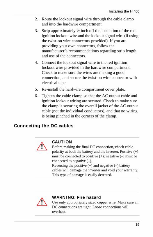
2. Route the lockout signal wire through the cable clamp and into the hardwire compartment.
3. Strip approximately ½ inch off the insulation of the red ignition lockout wire and the lockout signal wire (if using the twist-on wire connectors provided). If you are providing your own connectors, follow the manufacturer’s recommendations regarding strip length and use of the connectors.
4. Connect the lockout signal wire to the red ignition lockout wire provided in the hardwire compartment. Check to make sure the wires are making a good connection, and secure the twist-on wire connector with electrical tape.
5. Re-install the hardwire compartment cover plate.6. Tighten the cable clamp so that the AC output cable and
ignition lockout wiring are secured. Check to make sure the clamp is securing the overall jacket of the AC output cable (not the individual conductors), and that no wiring is being pinched in the corners of the clamp.
Connecting the DC cables
CAUTIONBefore making the final DC connection, check cable polarity at both the battery and the inverter. Positive (+) must be connected to positive (+); negative (–) must be connected to negative (–).Reversing the positive (+) and negative (–) battery cables will damage the inverter and void your warranty. This type of damage is easily detected.
WARNING: Fire hazardUse only appropriately sized copper wire. Make sure all DC connections are tight. Loose connections will overheat.
19

Installing the HI400
Follow the procedures given below to connect the battery to the DC input terminals. The cables should be as short as possible and large enough to handle the required current, in accordance with the electrical codes or regulations applicable to your installation. As noted above, the recommended cable size is No. 8 AWG for compliance with NEC, CEC, and RV codes (assuming a 40 amp DC fuse).
To ensure maximum performance from the inverter, do not route your DC cables through a DC distribution panel, battery isolator, or other device that will cause additional voltage drops.
Connecting the battery to the DC input
To make the DC connections:1. Cut the DC cables to the correct length with enough
insulation stripped off so you can properly install the type of terminals you will be using at the battery end. At the HI400 end, strip the wire 3/8 inch.
2. Assign one cable to be positive (+) and one cable to be negative (–). Mark both ends of each cable to avoid confusion during installation.
3. Switch the On/Off switch into the off position (if you have not already done so).
4. Route the DC cables from the battery bank to the inverter.5. Install a DC breaker or a fuse and disconnect in the
positive side of the circuit, as close as possible to the battery. Turn off the breaker or open the disconnect switch.
6. Attach the negative (–) cable to the negative (–) battery terminal (or to the current shunt if a shunt is used) using whatever connector you have selected. Tighten the connection according to the manufacturer’s recommendation.
20

Installing the HI400
7. Insert the other end of the negative (–) cable into the negative (–) terminal on the HI400 and tighten the terminal screw. Ensure all strands of wire are inside the connector (no stray strands). The terminal manufacturer’s recommended tightening torque is 21 inch-pounds.
8. Attach the positive (+) cable to the breaker or fuse and disconnect combination installed on the battery positive (+) terminal in step 5. Tighten the connection according to the manufacturer’s recommendations.
9. Insert the other end of the positive (+) cable into the positive (+) terminal on the HI400 and tighten the terminal screw. Ensure all strands of wire are inside the connector (no stray strands). The terminal manufacturer’s recommended tightening torque is 21 inch-pounds.
10. Verify the polarity of the DC connections is correct: positive (+) on the inverter connected to the positive (+) on the battery, and negative (–) connected to the negative (–).When you are ready to operate the inverter, close the DC circuit breaker or disconnect switch to supply DC power to the inverter.
Connecting the DC ground
The chassis ground lug on the DC end of the inverter is used to connect the chassis of the inverter to your system’s DC grounding point as required by installation codes for some installations.
Use copper wire that is either bare or provided with green insulation. Do not use the DC ground lug for your AC output grounding wire (see the AC wiring instructions on page 12 in this section).
To connect the DC ground:
➢ Connect a No. 8 AWG copper wire between the HI400’s chassis ground lug and the DC grounding point for your system.
21

Installing the HI400
In an RV or vehicle installation, this will usually be the vehicle chassis or a dedicated DC ground bus.
Connecting the AC input cord
To connect the AC input cord:➢ Plug the AC input cord (located at the back of the
inverter) into a properly grounded 120 Vac, 15 A receptacle connected to an external shorepower source such as a utility grid or a generator.
When the shorepower AC source is supplied, the HI400 will transfer the loads to the shorepower source and turn off the inverter.
When the shorepower AC source is disconnected or fails, the HI400 will automatically turn on the inverter and transfer the loads to inverter power.
WARNING: Shock hazardConnect the AC input cord only to a properly grounded standard 120 Vac, 15 A receptacle. If the correct type of receptacle is not available, have an electrician install one.
Note: Connecting the AC input cord to the AC output receptacle on the HI400 GFCI version will not power loads and will cause the unit to malfunction. There should not be any damage.
22

Installing the HI400
Checks prior to initial power-up
Before powering up your inverter, ensure these conditions are met:
❐ On/Off power switch is in the off position.
❐ Positive (+) battery cable is connected to the
positive (+) battery terminal.
❐ Negative (–) battery cable is connected to the
negative (–) battery terminal.
❐ Battery voltage is within the proper range for this unit (10.0 – 15.0 Vdc).
❐ DC Fuse is intact (not blown).
Starting up and testing your installation
To turn on the HI400:1. Turn the On/Off power switch on the front panel to the on
position. The green ON INVERTER LED indicator illuminates.
2. Plug a load into the GFCI receptacle on the front panel. Apply a load of 400 watts or less.
3. Test the transfer feature by plugging the AC input cord into the shorepower source receptacle. The inverter will transfer with the power switch in either the on or off position.
WARNINGThe front panel power switch does not disconnect DC or AC input power to the unit.
23

24
Operation
Chapter 3 “Operation” explains how to operate the HI400 Inverter.
25
Operation features
Operation features
Inverter on and off
The On/Off power switch on the front panel turns the HI400 inverter on or off:
• In the On position, the green inverter On LED indicator illuminates and the unit begins inverting if AC shorepower is not present. The HI400 is now operational and you can apply a load requiring less than 400 watts.
• In the Off position, the inverter AC output is turned off, but if AC shorepower is present, the hardwire and GFCI outputs will be energized and loads will operate. With the switch in the Off position, the unit does not draw any battery power, except as required to run the fan until the unit cools off.
Ground fault circuit interrupter (GFCI) protection
The GFCI with hardwire version contains a GFCI receptacle that protects the hardwire output and the receptacle output against a ground fault.
Correcting a ground fault
When a fault condition is detected, the reset button on the GFCI receptacle pops out and power to the load is interrupted.
To resume normal operation, determine and correct the ground fault, then push the reset button in.
CAUTIONRead all operating instructions before operating the HI400.
26
Operation features
Monthly testing
Once a month, with either AC shorepower or inverter power present, press the test button on the GFCI receptacle. The reset button should pop out. Push it to reset the GFCI, and continue normal operation. This should be completed on a monthly basis.
If the reset button does not pop out, the GFCI may have failed. Disconnect AC and DC power to the unit and have a qualified service person look at it.
Alternate AC source
An AC input cord is provided at the back of the unit allowing for alternate source AC power. Plug the input cord on the back of the HI400 into a shorepower receptacle. The load can be run from the alternate source when it is present.
When the shorepower source is not present, the internal transfer relay will automatically transfer the load to inverter power. This transfer relay functions whether the power switch is in the on or off position.
Ignition lockout
The inverter automatically shuts off when the ignition lockout is engaged. This occurs when the power switch is in the On position and a 12 volt signal (not to exceed 16 Vdc) is applied to the ignition lockout wire. Refer to page 18 for details.
Low battery condition
When the low battery red LED light illuminates, the battery voltage has dropped below 10.5 Vdc. When the battery voltage drops below 10.0 Vdc, the inverter turns off to prevent further discharging of the battery by the HI400.
27
Inverter loads
Inverter loads
The HI400 will operate most AC loads within its power rating (400 watts/3.3 amps).
Typical loads that can be used on the HI400 are as follows:
• Laptops• Small TVs• Handheld computing devices• VCRs• Camcorders• Other light duty AC devices
Operating several loads at once
If you are going to operate several loads from the HI400, turn them on separately after you have turned the inverter on. This ensures that the inverter does not have to deliver the starting current for all the loads at once. The HI400 can handle several loads as long as they do not exceed 400 watts in total.
Problem loads
Some appliances may be damaged if they are connected to the HI400:
• Electronics that modulate RF (radio frequency) signals on the AC line will not work and may be damaged.
• Speed controllers found in some fans, kitchen appliances, and other loads may be damaged.
CAUTION: Modified sine wave (MSW)Some appliances may be damaged by the HI400’s MSW output.
28

Inverter loads
• Some chargers for battery packs used in power hand tools. These affected chargers display a warning label stating that dangerous voltages are present at the battery terminals.
If you are unsure about powering any load with the HI400, contact the appliance manufacturer.
Turning the inverter off between charges
When the power switch is on but no power is being supplied to a load, the inverter idles and draws less than 400 mΑ from the battery.
Because of this current draw, the battery may need to be recharged after a few days. If you are not using your inverter, turn it off.
Battery charging frequency
When possible, recharge your batteries when they are about 50% discharged or before. This gives them a much longer life cycle than recharging when they are almost completely discharged. For more information about battery chargers, see our web site at www.xantrex.com
29

30

Maintenance and Troubleshooting
Chapter 4 “Maintenance and Troubleshooting” will help you identify common problems that can occur with the HI400 Inverter.Read this chapter before calling Xantrex Customer Service. If you cannot solve the problem, record the information asked for on page 51. This will help our Customer Service Representatives to assist you better.
31

Maintenance
Maintenance
Minimal maintenance is required to keep your HI400 operating properly.
Periodically you should• clean the exterior of the unit with a damp cloth to prevent
the accumulation of dust and dirt.• ensure the DC cables are secure at both the HI400 and the
battery.
Troubleshooting
Common problems
Buzz in audio equipment
Some inexpensive stereo systems have inadequate internal power supply filtering and buzz slightly when powered by the HI400. The best solution is to use an audio system with a good quality filter.
Television interference
The HI400 is shielded to minimize interference with TV signals. If TV signals are weak, you may see interference in the form of lines scrolling across the screen. Try one of these suggestions to minimize or eliminate the problem:
• Use an extension cord to increase the distance between the HI400 and the TV, antenna, and cables.
WARNING: Shock hazardDisconnect all sources of AC and DC power before doing any routine maintenance.
32

Troubleshooting reference
• Adjust the orientation of the HI400, television, antenna, and cables.
• Maximize TV signal strength by using a better antenna; use a shielded antenna cable where possible.
• Try a different TV. Different models vary considerably in their susceptibility to interference.
Troubleshooting reference
Four common problems with the HI400 are as follows:
• Low battery • Thermal shutdown• Electronic shutdown • No AC output
WARNING: Electric shock hazardDo not remove the cover or disassemble the HI400. It does not contain any serviceable parts and attempting to service the unit yourself could result in electrical shock or burn.
Table 5 Troubleshooting reference
Problem Possible Cause Solution
Low battery shutdown(Low battery LED illuminated red)
Battery under voltage
Check battery voltage:• If the voltage is low, charge the
battery. • If the voltage is normal, check for
loose battery connection.
Thermal shutdown(No LED illuminated)
Over temperature Inverter automatically restarts when the temperature of components decreases. Remove some loads. Be sure there is adequate air flow to both sides of the unit for proper cooling.
33
Troubleshooting reference
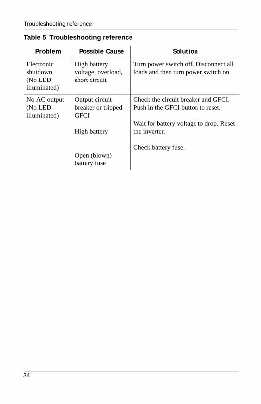
Electronic shutdown(No LED illuminated)
High battery voltage, overload, short circuit
Turn power switch off. Disconnect all loads and then turn power switch on
No AC output(No LED illuminated)
Output circuit breaker or tripped GFCI
High battery
Open (blown) battery fuse
Check the circuit breaker and GFCI. Push in the GFCI button to reset.
Wait for battery voltage to drop. Reset the inverter.
Check battery fuse.
Table 5 Troubleshooting reference
Problem Possible Cause Solution
34

Specifications
Appendix A “Specifications” contains electrical and physical specifications for the HI400 Inverter.
35

Electrical
Electrical
Physical
Specifications are subject to change without notice.
Output power• continuous• surge capacity
400 W550 W
Output voltage 120 Vac RMS ±5%
Output frequency 60 Hz nominal
Output wave form Modified sine wave
Transfer switch 4 Amp AC
High battery shutdown 15.0 V
Low battery shutdown 10.0 V
Efficiency Approximately 80-90%
No load current draw (switch on) Less than 400mA
Length 9.7 inches (24.6 cm)
Width 6.5 inches (16.5 cm)
Height 3.5 inches (8.9 cm)
Weight 4 lb (1.8 kg)
36

Battery Types and Sizes
Appendix B contains “Battery Types and Sizes.” The batteries you use strongly affect the performance of the HI400 Inverter. It is important to connect the inverter to the correct size and type of battery.The information in this appendix will help you select, connect, and maintain batteries that are most appropriate for your application.
37

Battery types
Battery types
Automotive starting batteries
The lead-acid battery you are most familiar with is probably the starting battery in your automobile. An automotive starting battery is designed to deliver a large amount of current for a short period of time (so it can start your engine). Only a small portion of the battery’s capacity is used when starting the engine and it is quickly recharged by the running engine.
This type of battery is not designed for repeated cycles where the battery is almost completely discharged and then recharged. If it is used in this kind of deep discharge service, it will wear out very rapidly.
Deep-cycle lead-acid batteries
Deep-cycle lead-acid batteries are designed for deep discharge service where they will be repeatedly discharged and recharged. They are marketed for use in recreational vehicles, boats, and electric golf carts — so you may see them referred to as RV batteries, marine batteries, or golf cart batteries.
For most applications of the HI400, Xantrex recommends you use one or more deep-cycle batteries that are separated from the vehicle’s starting battery by a battery isolator.
A battery isolator is a solid-state electronic circuit that allows equipment to be operated from an auxiliary battery without danger of discharging the vehicle’s starting battery. During vehicle operation, the battery isolator automatically directs the charge from the alternator to the battery requiring the charge.
Battery isolators are available at marine and RV dealers and most auto parts stores.
38
Battery size
Battery size
Battery size or capacity is as important as the battery type for efficient operation of your loads. Xantrex recommends that you purchase as much battery capacity as possible.
A number of different standards are used to rate battery energy storage capacity. Automotive and marine starting batteries are normally rated in cranking amps. This rating is not relevant to an inverter which runs continuous loads. Deep-cycle batteries use a more suitable rating system, either “amp-hours” (“Ah”) or “reserve capacity” in minutes.
Battery reserve capacity Battery reserve capacity is a measure of how long a battery can deliver a certain amount of current—usually 25 amps. For example, a battery with a reserve capacity of 180 minutes can deliver 25 amps for 180 minutes before it is completely discharged.
Amp-hour (Ah) capacity Amp-hour capacity is a measure of how many amps a battery can deliver for a specified length of time — usually 20 hours. For example, a typical marine or RV battery rated for 100 Ah can deliver 5 amps for 20 hours (5 A x 20 hours = 100 Ah).
This same battery can deliver a higher or lower current for less or more time, limited approximately by the 100 Ah figure (for example, 50 A for 2 hours, or 200 A for ½ hour), but usually the capacity figure given is only accurate at the specified rate (20 hours).
CAUTIONThe HI400 must only be connected to batteries with a nominal output voltage of 12 volts. The HI400 will not operate from a 6 volt battery and will be damaged if connected to a 24 volt battery.
39
Estimating battery requirements
To calculate the battery capacity you require, read “Estimating battery requirements” and “Battery sizing example” on page B–41, and then complete the “Battery sizing worksheet” on page B–42.
Estimating battery requirements
To determine how much battery capacity you need:1. Determine how many watts are consumed by each
appliance you will operate from the HI400. You can normally find this on a label on the product. If only the current draw is given, multiply it by 115 to get the power consumption in watts.
2. Estimate how many hours each appliance will be operating each day.
3. Calculate the daily watt-hours needed for each appliance.4. Add the total number of watt-hours needed for all the
appliances and multiply it by the number of days between charges.
5. Divide the total watt-hours of AC load between charges by 10. This gives the battery Ah used between charges.
6. Double the total Ah used between charges to get the recommended battery size in Ah.
See the battery sizing example that follows on the next page.
40

Estimating battery requirements
Battery sizing example
This battery sizing example illustrates a typical calculation, assuming an opportunity to charge the batteries every three days.
This example illustrates how quickly your battery needs can escalate. To reduce the required battery size, you can recharge more frequently or conserve energy by eliminating or reducing the use of some loads.
When sizing your battery, resist the temptation to skip the last step of this calculation (multiplying by 2). More capacity is better since you will have more reserve capacity, be better able to handle large loads and surge loads, and your battery won't be discharged as deeply. Battery life is directly dependent on how deeply the battery is discharged. The deeper the discharge, the shorter the battery life. Most battery manufacturers recommend limiting the “depth of discharge” to 50% of the battery capacity.
Appliance (A) Power consumption
(B) Operating time per day
Daily watt-hours needed
for this appliance(= A x B)
19” Color TV 100 W 2 hours 200 Wh
Power drill 400 W 1 hours 400 Wh
Computer system 300 W 2 hours 600 Wh
Total daily watt-hours of AC load 1200 Wh
x Number of days between charges 3
= Total watt-hours of AC load between charges 3600 Wh
Battery Ah used between charges (divide by 10) 360 Ah
Recommended Battery Bank Size in Ah (multiply by 2) 720 Ah
41

Estimating battery requirements
Battery sizing worksheet
Use the following worksheet to calculate your battery needs. To ensure sufficient battery capacity, be generous when estimating the operating time per day for each of your loads.
Appliance(A)
Power consumption
(B)Operating time
per day
Daily watt-hours
needed for this
appliance(= A x B)
W hours Wh
W hours Wh
W hours Wh
W hours Wh
W hours Wh
W hours Wh
W hours Wh
W hours Wh
Total daily watt-hours of AC load Wh
x Number of days between charges
= Total watt-hours of AC load between charges Wh
Battery Ah used between charges (divide by 10) Ah
Recommended Battery Bank Size in Ah (multiply by 2) Ah
42
Using multiple batteries
Using multiple batteries
As your power requirements increase, you may need to use more than one battery to obtain sufficient capacity. Read “Two batteries connected in parallel” and “Two separate battery banks” to determine whether two batteries or two battery banks are more appropriate for your applications.
Two batteries connected in parallel
Two identical batteries can be connected (positive (+) to positive and negative (–) to negative) in a parallel system. A parallel system doubles capacity and maintains the voltage of a single battery.
Two separate battery banks
If you need more than two batteries (or are using different makes or models of batteries), Xantrex recommends that you install two separate battery banks and a battery selector switch.
By installing a battery selector switch, you can select between the two battery banks, use both banks in parallel, or disconnect both banks from the load. Battery selector switches are available at marine and RV dealers.
CAUTIONDo not connect the following in parallel: batteries made by different manufacturers, different types of batteries, batteries that have different Ah ratings. Decreased battery life and improper charging will result.
43

Battery tips
Battery tips
Temperature sensitivity The capacity of lead-acid batteries is temperature sensitive. Battery capacity is rated at 77 ºF (25 ºC). At 0º F (–20 ºC), the Ah capacity is about half the rated capacity. You should consider temperature when designing your system.
Low temperatures If extremely low temperatures are expected where the inverter is going to be located, you should consider a heated equipment room. If the system is located in an unheated space, an insulated battery enclosure is recommended.
High temperatures The batteries should also be protected from high temperatures. These can be caused by high ambient temperatures, solar heating of the battery enclosure, or heat released by a nearby engine or generator. High battery temperatures shorten battery life and therefore you should ventilate the enclosure and use shade and insulation as appropriate.
Note: Review “Precautions when working with batteries” on page vii, before working with the batteries in your system.
WARNING: Explosive/corrosive gasesLead-acid batteries may emit hydrogen, oxygen, and sulphuric acid fumes when recharging. To reduce the risk of explosion:• Vent the battery compartment to prevent the
accumulation of gases.• Do not install electronic or electrical equipment in the
battery compartment.• Do not smoke or use an open flame when working
around batteries.
44

Battery tips
Discharged batteries Do not leave batteries in a discharged state for more than a day or two. They will undergo a chemical process (sulfation) that can permanently damage the battery. As well, batteries self-discharge over a period of three to six months, so they should be recharged periodically even if they are not being used.
Electrolyte level If your batteries are not the “maintenance-free” type, check the electrolyte level at least once a month. Excessive fluid loss is a sign of overcharging. Replenish the electrolyte using distilled water only.
Battery connections Connections to battery posts must be made with permanent connectors that provide a reliable, low-resistance connection. Do not use alligator clips. Clean the connections regularly and prevent corrosion by using a protective spray coating or vaseline.
Battery state of charge You can measure battery state of charge with a hydrometer or, more easily, with a voltmeter. Use a digital voltmeter than can display tenths or hundredths of a volt when measuring 10 to 30 volts. The batteries should be tested with no load or charge source (batteries disconnected) and should be open circuit for at least one hour.
The following table gives approximate state of charge for a lead-acid deep-cycle battery at 77 ºF (25 ºC):
Battery voltage State of charge
12.7–13.0 100%
12.5–12.6 80%
12.3–12.4 60%
12.1–12.2 40%
11.9–12.0 20%
45

46

Warranty and Product Information
Appendix C “Product and System Information” contains the warranty and return information for the HI400 Inverter.
47

Warranty information
Warranty information
What does this warranty cover? Xantrex manufactures its products from parts and components that are new or equivalent to new, in accordance with industry standard practices. This warranty covers any defects in workmanship or materials.
How long does the coverage last? This warranty lasts for one (1) year from the date of purchase. Implied warranties of merchantability and fitness for a particular purpose are limited to one year from date of purchase. Some jurisdictions do not allow limitations on how long an implied warranty lasts, so the above limitation may not apply to you.
What does this warranty not cover? This warranty will not apply where the product has been misused, neglected, improperly installed, physically damaged or altered, either internally or externally, or damaged from improper use or use in an unsuitable environment. Xantrex does not warrant uninterrupted operation of its products. Xantrex shall not be liable for damages, whether direct, incidental, special, or consequential, or economic loss even though caused by the negligence or fault of Xantrex. Some jurisdictions do not allow the exclusion or limitation of incidental or consequential damages, so the above limitation or exclusion may not apply to you.
What will Xantrex do? At its option, Xantrex will repair or replace the defective product free of charge. Xantrex will, also at its option, use new and/or reconditioned parts made by various manufacturers in performing warranty repair and building replacement products. If Xantrex repairs or replaces a product, its warranty term is not extended. Xantrex owns all parts removed from repaired products.
Service during warranty? In order to qualify for the warranty, a dated proof of purchase must be provided and the product must not be disassembled or modified without prior authorization by Xantrex. If your product requires warranty
48

Returning a product
service, please return it to the place of purchase along with a copy of your dated proof of purchase. If you are unable to contact your merchant, or the merchant is unable to provide service, contact Xantrex directly:
Returning a product
You must obtain a Return Material Authorization (RMA) number from Xantrex before returning a product directly to Xantrex.
When you contact Xantrex to obtain service, be prepared to supply the following information:
• Serial number of your inverter• Date of purchase• Information about the installation and use of the inverterIf you are returning a product from the USA or Canada:
1. Obtain an RMA number and a shipping address from Xantrex. Products returned without an RMA number or shipped collect will be refused.
2. Package the inverter safely, preferably using the original packing materials. Include the following with your shipment:
3. The RMA number4. A copy of your dated proof of purchase5. A return address where the repaired unit can be shipped6. A contact telephone number7. A brief description of the problem
Web: www.xantrex.com
Email: [email protected]
Phone: 800-446-6180 (toll free)
Fax: 360-925-5143
49

Out-of-warranty service
8. Ship the inverter to the address provided in Step 1, freight prepaid. Xantrex recommends that you obtain proof of delivery.
How other laws apply This warranty gives you specific legal rights, and you may also have other rights which vary from jurisdiction to jurisdiction.
For our Canadian customers When used herein “implied warranties of merchantability and fitness for a particular purpose” includes all warranties and conditions, express or implied, statutory or otherwise, including without limitation implied warranties and conditions of merchantability and fitness for a particular purpose.
Out-of-warranty service
If the warranty period for your HI400 Inverter has expired, if the inverter was damaged by misuse or incorrect installation, if other conditions of the warranty have not been met, or if no dated proof of purchase is available, your inverter may be serviced or replaced for a flat fee.
To return your HI400 for out of warranty service, contact Xantrex Customer Service for a Return Material Authorization (RMA) number and follow the other steps outlined in “Warranty information” on page C–48.
Payment options such as credit card or money order will be explained by the Customer Service Representative. In cases where the minimum flat fee does not apply, as with incomplete inverters or inverters with excessive damage, an additional fee will be charged. If applicable, you will be contacted by Customer Service once your inverter has been received.
50

Contacting Xantrex Customer Service
Contacting Xantrex Customer Service
If none of the troubleshooting suggestions work, you will need to call Xantrex Customer Service. If possible, note the circumstances surrounding the failure below. This will assist the service technician in diagnosing the problem quickly.
Other Xantrex products
To see the range of inverters and chargers offered by Xantrex, visit our web site at www.xantrex.com
How long have you had the inverter?
Serial number
Battery types and sizes
Entertainment equipment running at shutdown
Were the LEDs flashing and if so, what pattern (slow blinks? fast blinks?)
Was the ambient temperature extremely hot or cold?
Were any DC appliances affected?
Has this happened before?
51

52

Index
AAC disconnects 11AC input cord 22, 23AC load circuit 13AC output cable, 3-conductor 9AC shorepower 11Ah. See amp-hour capacity.alternating current 11amp-hour (Ah) capacity 39appliances
battery-operated viiicurrent draw 40power consumption 40, 42rechargeable viii
Bbatteries
amp-hour (Ah) capacity 39automotive starting 38, 39charging frequency 29connecting two in parallel 43deep-cycle lead-acid 38depth of discharge 41discharged 45electrolyte level 45golf cart 38marine 38
reserve capacity 39, 41RV 38self-discharge 45temperature sensitivity 44tips 44using multiple 43using two battery banks 43
battery bank 20battery banks, described 43battery connections 45battery isolator 20battery isolator, using 38battery packs viiibattery reserve capacity 39battery selector switch 43battery size
estimating example 41estimating worksheet 42estimating your needs 39, 40
battery types 38
Cchassis ground lug 21copper conductors 9crimp connectors 9CSA (Canadian Standards Association)
certification 2
53

Index
DDC cable 9DC circuit breaker 21DC distribution panel 20DC ground bus (dedicated) 21DC grounding point 21DC input terminals 19DC input wiring 20depth of discharge (DOD) 41disconnect switch 21
Eelectrical code requirements 12electrolyte level 45explosive gases vi
Ffeatures
back panel 5front panel 4ground fault circuit interrupter
(GFCI) 2ignition lockout 3low voltage shutdown 2multiple loads 2surge capability 2transfer switch 3
flanges 16
Hhydrometer 45
Iignition lockout wire 10, 17, 18installation codes 8
54
Canadian Electrical Code (NEC) 8Canadian Standards Association
(CSA) 8RV Industry Association (RVIA) 8U.S. National Electrical Code (NEC)
8installation features 10
AC input cord 10cable clamp 10chassis grounding lug 10DC input terminals 10designing your installation
ground fault circuit interrupters (GFCIs) 14
tested GFCI models 15flying leads 10ground screw 10hardwire compartment 10ignition lockout wire 10wire connectors 10
installation procedureschoosing a location 15connecting ("hardwiring") the AC
output 17connecting the AC input cord 22connecting the DC cables 19
connecting the battery to the DC input 20
connecting the DC ground 21designing your installation 11
AC disconnects and over-current protection devices 12
AC output neutral bonding 13AC output wiring 12AC shorepower 11

Index
batteries 14DC cabling 14DC disconnects and over-current
devices 13mounting inverter 16
Llockout signal wire 18
Mmalfunction 22materials list 6mounting screws 9MSW (modified sine wave) 2
Nneutral conductor 13No. 14 AWG 9, 17No. 18 AWG 18No. 8 AWG 9
OOn inverter LED (green) 23On/Off power switch 23operating features 4
AC input cord 5air vent 5alternate AC source 27chassis grounding lug 5circuit breaker 4dual AC receptacle 4fan vent 4GFCI protection 26GFCI reset button 4low battery 4
negative and positive cabling terminals 5
On inverter 4On/Off switch 4problem loads 28strain relief 5typical loads 28wiring compartment plate panel 5
operation featuresproblem loads
electronics that modulate RF (radio frequency) 28
speed controllers 28over-current protection 12
Ppolarity of DC connections 21power-up check 23preparing for installation 8
AC cabling, DC cabling and ground information 7
detailed installation procedures 7installation tools and materials 7locations and environments for
mounting the inverter 7safety instructions and installation
codes 7
Rreserve capacity 39Return Material Authorization number
(RMA) 49routine maintenance
cleaning your unit 32securing DC cables 32
55

Index
Ssafety information vserial number 49starting batteries 39state of charge 45
Ttools and materials 9transfer feature 23troubleshooting 33
buzz in audio equipment 32common problems 33
electronic shutdown 33low battery 33no AC output 33thermal shutdown 33
possible causes 33possible problems 33reference table 33solutions 33television interference 32
Uutility grid power 11
Vvehicle chassis 21ventilation 44ventilation openings vversions
hardwire and GFCI outlet 2hardwire only 2
voltage drop 20voltmeter 45
56
Wwarranty 48
Canadian customers, for 50contacting Xantrex customer service
51legal rights under warranty 50length of coverage 48not covered under warranty 48out-of-warranty service 50returning a product 49service during warranty 48what does it cover 48what will Xantrex do 48
wide slot screwdriver 9wire stripper 9
XXantrex
contact information 49web site 51